WO2023190865A1 - 光干渉断層撮影装置、光干渉断層撮影システム、光干渉断層撮影法及び検査方法 - Google Patents
光干渉断層撮影装置、光干渉断層撮影システム、光干渉断層撮影法及び検査方法 Download PDFInfo
- Publication number
- WO2023190865A1 WO2023190865A1 PCT/JP2023/013172 JP2023013172W WO2023190865A1 WO 2023190865 A1 WO2023190865 A1 WO 2023190865A1 JP 2023013172 W JP2023013172 W JP 2023013172W WO 2023190865 A1 WO2023190865 A1 WO 2023190865A1
- Authority
- WO
- WIPO (PCT)
- Prior art keywords
- light
- sample
- optical coherence
- coherence tomography
- objective lens
- Prior art date
Links
- 238000012014 optical coherence tomography Methods 0.000 title claims abstract description 157
- 238000000034 method Methods 0.000 title claims description 43
- 238000007689 inspection Methods 0.000 title claims description 12
- 238000003325 tomography Methods 0.000 claims abstract description 55
- 239000000523 sample Substances 0.000 claims description 207
- 238000000149 argon plasma sintering Methods 0.000 claims description 12
- 238000002834 transmittance Methods 0.000 claims description 5
- 230000003287 optical effect Effects 0.000 description 76
- 239000013307 optical fiber Substances 0.000 description 15
- 238000001514 detection method Methods 0.000 description 6
- 238000003384 imaging method Methods 0.000 description 5
- 239000000463 material Substances 0.000 description 5
- 238000010586 diagram Methods 0.000 description 3
- 239000011521 glass Substances 0.000 description 3
- 239000011347 resin Substances 0.000 description 3
- 229920005989 resin Polymers 0.000 description 3
- 230000007547 defect Effects 0.000 description 2
- 239000005338 frosted glass Substances 0.000 description 2
- 238000004519 manufacturing process Methods 0.000 description 2
- 230000010287 polarization Effects 0.000 description 2
- 238000005070 sampling Methods 0.000 description 2
- 229910000530 Gallium indium arsenide Inorganic materials 0.000 description 1
- VYPSYNLAJGMNEJ-UHFFFAOYSA-N Silicium dioxide Chemical compound O=[Si]=O VYPSYNLAJGMNEJ-UHFFFAOYSA-N 0.000 description 1
- 230000002238 attenuated effect Effects 0.000 description 1
- 210000005252 bulbus oculi Anatomy 0.000 description 1
- 230000000694 effects Effects 0.000 description 1
- 210000001508 eye Anatomy 0.000 description 1
- 239000000835 fiber Substances 0.000 description 1
- 230000004907 flux Effects 0.000 description 1
- 230000001678 irradiating effect Effects 0.000 description 1
- 238000005259 measurement Methods 0.000 description 1
- 238000012634 optical imaging Methods 0.000 description 1
- 210000000056 organ Anatomy 0.000 description 1
- 239000002245 particle Substances 0.000 description 1
- 230000035945 sensitivity Effects 0.000 description 1
- 230000003595 spectral effect Effects 0.000 description 1
- 238000010408 sweeping Methods 0.000 description 1
Images
Classifications
-
- G—PHYSICS
- G01—MEASURING; TESTING
- G01N—INVESTIGATING OR ANALYSING MATERIALS BY DETERMINING THEIR CHEMICAL OR PHYSICAL PROPERTIES
- G01N21/00—Investigating or analysing materials by the use of optical means, i.e. using sub-millimetre waves, infrared, visible or ultraviolet light
- G01N21/17—Systems in which incident light is modified in accordance with the properties of the material investigated
Definitions
- the present disclosure relates to an optical coherence tomography apparatus, an optical coherence tomography system, an optical coherence tomography method, and an inspection method.
- OCT optical coherence tomography
- An optical coherence tomography device splits light from a light source using a beam splitter, irradiates the sample and a reference mirror separately to obtain reflected light, and eliminates the interference of these reflected lights that have passed through separate optical paths. It is known to perform tomography using this method (see, for example, Patent Document 1).
- the present disclosure provides an optical coherence tomography apparatus capable of tomographically imaging a wide area at once and tomographically imaging a distant target, an optical coherence tomography system using the same, and an optical coherence tomography system using the same.
- the purpose is to provide imaging methods and inspection methods.
- the present disclosure includes an objective lens that focuses light from a light source on a sample, Optical coherence tomography that performs tomography of the sample based on interference between sample light that is reflected light from the sample and reference light that is reflected light from a reference surface provided between the objective lens and the sample.
- a photographing device Both the sample light and the reference light pass through the objective lens, The light from the light source that has passed through the objective lens is irradiated onto the sample at a wide angle,
- the above-mentioned reference plane relates to an optical coherence tomography apparatus constituted by a light scattering body.
- the objective lens is a short focus lens or a wide angle lens.
- the focal position of the objective lens is variable.
- the light scattering material has a haze value of 5 to 95% in the wavelength range of 400 to 1750 nm.
- the light scattering material has a total light transmittance of 10 to 90% in the wavelength range of 400 to 1750 nm.
- the reference surface is a plane.
- the optical coherence tomography apparatus includes a probe having the objective lens.
- the optical coherence tomography apparatus includes a plurality of the probes.
- the probe is arranged so as to be mechanically movable.
- the present disclosure also relates to an optical coherence tomography system including the optical coherence tomography apparatus and a movement mechanism that mechanically moves the probe included in the optical coherence tomography apparatus.
- the present disclosure also relates to an optical coherence tomography method using the optical coherence tomography apparatus or the optical coherence tomography system.
- the distance between the objective lens and the sample being 2 cm or more and less than 2 m.
- the present disclosure also relates to an inspection method for inspecting the internal state of a sample based on image data obtained by tomographically photographing the sample using the optical coherence tomography method.
- an optical coherence tomography apparatus capable of tomographically imaging a wide area at once and tomographically imaging a distant object, an optical coherence tomography system using the same, and an optical coherence tomography system using the same. Coherence tomography and inspection methods can be provided.
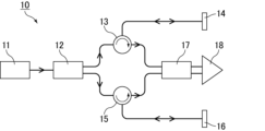
- FIG. 1 is a schematic diagram showing an example of a conventional optical coherence tomography (OCT) apparatus.
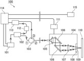
- FIG. 1 is a schematic diagram showing an example of an OCT apparatus of the present disclosure.
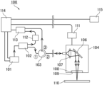
- FIG. 3 is a schematic diagram showing another example of the OCT apparatus of the present disclosure.
- an optical coherence tomography (OCT) apparatus using a Michelson interferometer as shown in FIG. 1 is commonly used.
- OCT optical coherence tomography
- light output from a light source 11 is split by a coupler 12 into a reference light that passes through an optical path that includes a circulator 13 and a reference mirror 14, and a sample light that passes through an optical path that includes a circulator 15 and a sample 16. occurs.
- the reference light and sample light are combined by a coupler 17, and an interference signal is detected by a photodetector 18.
- OCT devices used in the medical field are focused on taking tomographic images of very narrow areas such as the eyeballs from close range with high precision. There is a problem in that it is difficult to apply to fields where tomography is required.
- the present inventors have constructed an OCT apparatus in which both sample light and reference light pass through an objective lens, so that the light from the light source that passes through the objective lens is irradiated onto the sample at a wide angle. discovered that the above problem could be solved by constructing the reference surface with a light scattering body, and completed the OCT apparatus of the present disclosure.
- the present disclosure includes an objective lens that focuses light from a light source on a sample, and includes sample light that is reflected light from the sample and reflected light from a reference surface provided between the objective lens and the sample.
- An optical coherence tomography apparatus that performs tomography of the sample based on interference with a certain reference light, wherein both the sample light and the reference light pass through the objective lens, and the light source passes through the objective lens.
- Light is irradiated on the sample at a wide angle, and the reference plane provides an OCT device constituted by a light scatterer.
- both sample light which is reflected light from a sample to be imaged
- reference light which is reflected light from a reference surface
- the sample light and reference light are generated from light from a light source.
- Light from the light source passes through an objective lens included in the OCT apparatus of the present disclosure and is focused on the sample.
- the reflected light from the sample becomes sample light.
- a part of the light from the light source is reflected by a reference surface provided between the objective lens and the sample, and becomes reference light.
- both the sample light and the reference light are generated from light from the light source that passes through the objective lens.
- the difference in environment between the sample light path and the reference light path is reduced. This makes it possible to further reduce deviations in the obtained tomographic images.
- Wide-angle irradiation refers to irradiation in a range where the angle ⁇ between the light beam incident on the sample surface and the perpendicular to the sample surface is 0 degrees or more and 90 degrees or less.
- the angle ⁇ may be more than 0 degrees, preferably 1 degree or more, more preferably 2 degrees or more, and may be less than 90 degrees, preferably 30 degrees or less. , more preferably 15 degrees or less. Note that the irradiation may be performed over the entire range described above.
- the wide-angle irradiation method includes (i) a method in which the light from the light source is converged by a short focal length lens as an objective lens, and the resulting converged light is irradiated at a wide angle by a scanning mirror, or ( ii) A method of irradiating the sample with light from the light source using a wide-angle lens as an objective lens. Particularly preferred is method (i).
- the objective lens short focal length lens
- the objective lens short focal length lens
- the angle at which the light is irradiated onto the sample and the sample can be adjusted. The degree of freedom in adjusting the distance can be increased.
- the light from the light source can be irradiated onto the sample over a wide angle by changing the inclination of the mirror surface of the scanning mirror so that the angle ⁇ falls within the above-mentioned range. can.
- the light from the light source can be irradiated onto the sample at a wide angle by performing irradiation with a configuration in which the angle of view ⁇ determined by the method described below is 0 degrees or more and 90 degrees or less.
- the angle of view ⁇ may be more than 0 degrees, preferably 1 degree or more, more preferably 2 degrees or more, and may be less than 90 degrees, preferably 30 degrees or less. Preferably, it is more preferably 15 degrees or less.
- the above-mentioned angle of view ⁇ is determined from the value of tan ⁇ below when the diagonally opposite ends of the image sensor included in the OCT apparatus are connected at the center of the lens.
- the image sensor may be provided in a detector (detector (1)) to be described later, and may be a CCD image sensor or an InGaAs photodiode.
- the incident light flux sufficiently reaches the corner of the range that the objective lens can capture, and that optical performance can be ensured within this range. It is preferable that the deviation in optical imaging is 10% or less.
- the objective lens is a short focus lens or a wide angle lens.
- the short focus lens is a condenser lens that has a focal length of 50 mm or less when focused at infinity using light with a wavelength of 800 to 1750 nm.
- the focal length of the short focus lens is more preferably 45 mm or less, more preferably 1 mm or more, and more preferably 2 mm or more.
- the focal length can be measured according to JIS B 7094 (ISO 517).
- the short focal length lens has a variable focal position (condensing distance). Since the focal position is variable, the focal position can be changed without replacing the objective lens.
- An example of a short focal length lens whose focal position is variable is a collimating lens that can adjust the distance between the lens and the exit of the optical fiber.
- the short focus lens has a variable focal length. Since the focal length is variable, the focal length can be changed without replacing the objective lens.
- the short focus lens may be a collimating lens such as an achromatic fiber collimator.
- the above short focus lens can be particularly suitably used in the method (i) above.
- the wide-angle lens may have a focal length of 200 mm or less, preferably 100 mm or less, more preferably 50 mm or less, and 40 mm or less when focused at infinity using light with a wavelength of 800 to 1750 nm. It is more preferable that it is below. Moreover, it may be 1 mm or more, preferably 2 mm or more, and more preferably 8 mm or more.
- the focal length can be measured according to JIS B 7094 (ISO 517).
- the wide-angle lens preferably has a variable focal position (condensing distance). Since the focal position is variable, the focal position can be changed without replacing the objective lens.
- the wide-angle lens has a variable focal length. Since the focal length is variable, the focal length can be changed without replacing the objective lens.
- the wide-angle lens may be a wide-angle camera lens.
- the wide-angle lens described above can be particularly preferably used in the method (ii) above.
- the reference plane is provided between the objective lens and the sample.
- the reference plane may be provided perpendicular to the optical axis of the objective lens, but is not limited thereto.
- the reference surface needs to be a surface that reflects at least a part of the light from the light source, and is easy to configure so that the sample light and reference light pass through a common optical path. It is preferable that the surface transmits a part of the light and reflects a part of the light. In this aspect, the light transmitted through the reference surface is focused on the sample to generate sample light, while the light reflected by the reference surface becomes reference light.
- the reference surface is preferably a flat surface, more preferably a flat surface of the reference member, and even more preferably a surface of the reference member on the sample side. It is preferable that the reference member transmits part of the light from the light source and reflects part of the light.
- the reference surface is composed of a light scatterer.
- the reference member may also be composed of a light scattering body.
- the light from the light source may be obliquely incident on the reference plane depending on the position.
- the reference surface by configuring the reference surface with a light scattering body, it is possible to easily obtain reflected light along the same optical path as the incident light from light that is obliquely incident on the reference surface. This makes it possible to perform tomography over a wide area at once, and also to perform tomography of a distant object.
- the light scattering material may have a haze value of 5 to 95% in a wavelength range of 400 to 1750 nm.
- the haze value is preferably 10% or more, more preferably 15% or more, further preferably 90% or less, and more preferably 80% or less.
- the haze value can be measured using a haze meter in accordance with JIS R 3106 (ISO 9050), JIS K 7361-1 (ISO 13468-1), and JIS K 7136 (ISO 14782).
- the light scatterer may have a total light transmittance of 10 to 90% in a wavelength range of 400 to 1750 nm.
- the total light transmittance is preferably 15% or more, more preferably 20% or more, and preferably 80% or less, more preferably 70% or less.
- the total light transmittance can be measured using a haze meter in accordance with JIS R 3106 (ISO 9050), JIS K 7361-1 (ISO 13468-1), and JIS K 7136 (ISO 14782).
- the light scattering body may be anything as long as it scatters the light from the light source.
- Examples include glass or resin with fine irregularities on the surface, such as frosted glass, frosted glass, and Fresnel lenses; glass or resin that has light-scattering bubbles, particles, etc. inside.
- glass or resin having fine irregularities on the surface is preferable as the light scattering body.
- the shape of the reference member may be any shape as long as it has a flat surface, and may be plate-like, cylindrical, prismatic, etc., but preferably cylindrical. When it is cylindrical, it does not necessarily have to be a perfect cylinder. Furthermore, when the reference member further has a plane other than the reference plane, the reference plane and the other plane do not necessarily have to be parallel.
- the thickness of the reference member is preferably, for example, 0.01 to 50 mm.
- the above thickness is more preferably 0.1 mm or more, even more preferably 0.3 mm or more, particularly preferably 0.5 mm or more, and more preferably 30 mm or less, and 20 mm or less. It is more preferable that it is, and it is especially preferable that it is 10 mm or less.
- the thickness of both the thinnest part and the thickest part is within the said range.
- the reference member satisfies the following relational expression (1).
- nd represents the optical thickness of the reference member, and Z max represents the measurable distance.
- the optical thickness is the product of the refractive index and the actual (geometric) thickness of the reference member.
- the measurable distance is expressed by the following relational expression (2).
- the reference member satisfies the following relational expression (3).
- n represents the refractive index of the reference member.
- WD represents the working distance of the OCT device.
- nd and Z max are as described above.
- the working distance is the distance from the frontmost surface of the objective lens on the sample side to the sample when focusing.
- the thickness of the reference member is preferably thick within a range that satisfies relational expression (3), since the intensity of the ghost image based on the back reflection can be further reduced. Further, it is also preferable that the rear basal surface of the reference member be inclined with respect to the reference surface. The above-mentioned effect becomes particularly noticeable when an anti-alias filter (low-pass filter), which will be described later, is provided.
- an anti-alias filter low-pass filter
- the reference member satisfies the following relational expression (4).
- nd m ⁇ Z max (4) (In the formula, nd and Z max are as above.
- m represents an integer of 1 or more.)
- m is preferably an integer of 1 or more and 20 or less, and is also preferably an integer of 1 or more and 10 or less.
- the reference plane may be located at a distance of 5 mm to 5 m from the objective lens.
- the distance is preferably 10 mm or more, more preferably 20 mm or more, and preferably 2 m or less, and more preferably 1 m or less.
- the OCT apparatus of the present disclosure may include the reference surface (reference member) described above.
- the light source may be a low coherence light source, and is preferably a frequency scanning light source that scans while changing the frequency (wavelength) over time.
- the above-mentioned frequency scanning light source includes a wavelength swept laser using a wavelength sweeping filter (driving by a polygon mirror, driving by a galvano mirror, etc.), FDML laser, MEMS wavelength swept light source (MEMS VCSEL, external cavity type MEMS Fabry-Perot laser, etc.) , SGDBR laser, etc. can be used.
- the light emitted from the light source includes visible light and infrared light, with near-infrared light (NIR) being preferred.
- NIR near-infrared light
- As the light beam it is preferable to use a light beam with a wavelength of 800 to 2000 nm. Among these, from the viewpoint of stability of the light source and reliability of the sensor, light beams having a center wavelength of 940 ⁇ 50 nm, 1100 ⁇ 50 nm, 1310 ⁇ 50, 1550 ⁇ 100, or 1750 ⁇ 100 nm are more preferable.
- the OCT apparatus of the present disclosure may include the light source described above.
- the OCT apparatus of the present disclosure performs tomography of the sample based on interference between the sample light and the reference light.
- the above-mentioned interference may be of any type that allows both the sample light and the reference light to pass through the objective lens, but it is preferably Fizeau-type interference or Mireau-type interference, and Fizeau-type interference is preferred. It is more preferable that there be.
- Types of OCT that can be employed in the OCT apparatus of the present disclosure include time domain OCT (TD-OCT), Fourier domain OCT (FD-OCT), and the like.
- FD-OCT include spectral domain OCT (SD-OCT), frequency scanning OCT (Swept Source OCT: SS-OCT), and the like.
- SD-OCT spectral domain OCT
- SS-OCT frequency scanning OCT
- SS-OCT is preferable because it has high sensitivity and a deep measurable depth.
- the OCT apparatus of the present disclosure includes a probe having the objective lens described above. There may be one or more probes.
- the probe may or may not have the reference surface (or reference member), but preferably has the reference surface (or reference member). Moreover, it is more preferable that the probe further includes a collimator and a scanning mirror, which will be described later.
- the OCT apparatus of the present disclosure includes a plurality of the probes
- tomography at different positions can be performed in parallel using the plurality of probes.
- information based on light of different frequencies may be acquired from the plurality of probes.
- tomography at different depths can be performed in parallel using the plurality of probes.
- the probe may be arranged to be mechanically movable. According to this configuration, tomography can be performed while mechanically moving the probe, so that tomography of a large sample can be easily performed.
- the moving direction of the probe is not particularly limited and may be determined depending on the range to be tomographically imaged, but for example, it may be in a direction that intersects with the optical axis of the objective lens, in which the probe is emitted from the objective lens to the sample side. It may be in a direction that intersects the optical path of the light beam, it may be in a direction along the shape of the sample, it may be in a direction along the sample surface, or it may be in a direction substantially parallel to the sample surface. .
- the above configuration can be realized, for example, by disposing the probe in a moving mechanism that will be described later.
- the probe is connected to the OCT apparatus main body (casing) via an optical fiber.
- the light from the light source as well as the sample light and reference light are transmitted through the optical fiber.
- tomography can be performed by positioning the probe near the object by adjusting the length of the optical fiber. Since the light from the light source, the sample light, and the reference light are all transmitted through the optical fiber, even if the optical fiber is lengthened, there will be no difference in environment between the sample optical path and the reference optical path, and the obtained tomographic image will be The deviation is small. Furthermore, since it is a wired type using the optical fiber, high-resolution OCT measurement can be performed even on a photographic subject located far away from the main body.
- the length of the optical fiber is not particularly limited and can be determined depending on the location of the object to be photographed, but for example, it may be 1 m or more, preferably 3 m or more, and more preferably 5 m or more. Preferably, the length is more preferably 10 m or more. Further, the length may be 100 m or less, or may be 50 m or less.
- the OCT device main body preferably includes, for example, the light source, and more preferably includes a circulator, a detector, a DAQ device, an arithmetic device, etc., which will be described later.
- the OCT apparatus of the present disclosure further includes a collimator that converts the light from the light source into parallel light.
- the collimator is preferably provided on an optical path between the light source and the reference surface, and more preferably provided on an optical path between the light source and the objective lens.
- the objective lens described above preferably a short focus lens
- the OCT apparatus of the present disclosure further includes a scanning mirror that scans the light from the light source that is focused on the sample.
- the scanning mirror is preferably provided on an optical path between the light source and the objective lens, and more preferably on an optical path between the collimator and the objective lens. This aspect is particularly suitable when the objective lens is a wide-angle lens. It is also preferable that the scanning mirror is provided on an optical path between the objective lens and the reference surface. This aspect is particularly suitable when the objective lens is a short focus lens.
- Examples of the scanning mirror include a galvano mirror, a polygon mirror, and a MEMS mirror.
- a galvano mirror is preferable, a uniaxial or biaxial galvano mirror is more preferable, and a biaxial galvano mirror is even more preferable.
- the OCT apparatus of the present disclosure further includes a drive device for driving the scanning mirror.
- the OCT apparatus of the present disclosure further includes a detector that outputs light from the light source to the objective lens side, detects the sample light and reference light that have passed through the objective lens, and detects the sample light and reference light. It is preferable to include a circulator that outputs the output on the side. In this aspect, the sample light and reference light can be transmitted by one circulator. With this configuration, the device can be made smaller and costs can be reduced compared to the case where separate circulators are provided through which the sample light and reference light pass, as shown in FIG. You can also do it.
- the circulator preferably has three or more ports, more preferably three ports.
- the circulator is preferably provided on an optical path between the light source and the objective lens, and more preferably on the optical path between the light source and the collimator.
- light from the light source is input through a first port on the side of the light source and output through a second port on the side of the objective lens.
- the sample light and reference light that have passed through the objective lens are input from a second port and output from a third port on the detector side.
- the OCT apparatus of the present disclosure further includes a detector (also referred to as detector (1)) that detects the sample light and reference light. It is preferable that the detector (1) detects an interference signal caused by the sample light and the reference light. There may be one or more detectors (1).
- the detector (1) is a differential photodetector.
- the detector (1) may have the function of amplifying the signal. Further, an amplifier may be provided separately.
- the OCT apparatus of the present disclosure further includes a coupler (coupler) that splits the light from the light source into split light 1 used to generate the sample light and reference light, and split light 2 used to remove the DC component of the interference signal.
- a coupler (coupler) that splits the light from the light source into split light 1 used to generate the sample light and reference light, and split light 2 used to remove the DC component of the interference signal.
- (1)) is preferably provided.
- the coupler (1) is preferably provided on an optical path between the light source and the objective lens, and more preferably on the optical path between the light source and the circulator.
- the intensity ratio between the split light 1 and the split light 2 is preferably 90:10 to 99:1, more preferably 92:8 to 98:2. By dividing into such intensity ratios, the DC component can be effectively removed from the interference signal.
- the OCT apparatus of the present disclosure further includes a detector (also referred to as detector (2)) that detects the split light 2.
- detector (2) may be the same detector as the detector (1) described above, or may be a different detector.
- the OCT apparatus of the present disclosure further includes an attenuator that attenuates the split light 2.
- the attenuator is preferably a variable optical attenuator (VOA).
- VOA variable optical attenuator
- the attenuator is preferably provided on the optical path between the coupler (1) and the detector (2) that detects the split light 2.
- the OCT apparatus of the present disclosure may further include a polarization module that adjusts the polarization state of light from the light source.
- the polarizing module is preferably provided on an optical path between the light source and the objective lens, and more preferably on the optical path between the light source and the coupler (1).
- the OCT apparatus of the present disclosure includes a plurality of the probes, it is preferable to include a coupler (also referred to as coupler (2)) that splits the light from the light source into light sent to each probe.
- the coupler (2) is preferably provided on an optical path between the light source and the objective lens, and more preferably on the optical path between the circulator and the collimator.
- the OCT device of the present disclosure may include a modulator that modulates the frequency of light.
- the modulator include an acousto-optic (AO) modulator and an electro-optic (EO) modulator.
- AO acousto-optic
- EO electro-optic
- a plurality of the above modulators may be provided corresponding to each probe. According to this configuration, information based on light of different frequencies can be acquired from the plurality of probes, and tomography at different depths can be performed in parallel using the plurality of probes. Images corresponding to different depths obtained by the plurality of probes can also be encoded in the depth direction and displayed simultaneously on a display device to be described later.
- the modulator is preferably provided on an optical path between the light source and the objective lens, and more preferably provided on an optical path between the circulator and the collimator.
- the OCT apparatus of the present disclosure includes a plurality of the above probes, it is preferable that the OCT apparatus includes a coupler (also referred to as coupler (3)) that couples light from the plurality of probes.
- a coupler also referred to as coupler (3)
- the coupler (2) described above can also be used as coupler (3).
- the coupler (3) is preferably provided on an optical path between the light source and the objective lens, and more preferably on the optical path between the circulator and the collimator.
- the OCT apparatus of the present disclosure further includes a data acquisition (DAQ) device that collects interference signals caused by the sample light and reference light.
- the DAQ device includes an A/D converter.
- the DAQ device converts the collected interference signal into digital data.
- the DAQ device may be one or more.
- the OCT apparatus of the present disclosure further includes an anti-alias filter (also referred to as a low-pass filter) that attenuates unnecessary frequency components exceeding the measurable distance (Z max ).
- the anti-aliasing filter is preferably provided on an optical path between the detector (1) and the DAQ device.
- the OCT apparatus of the present disclosure further includes an arithmetic device that generates an optical coherence tomographic image based on interference signals of the sample light and reference light.
- the arithmetic device generates an optical coherence tomographic image by converting the interference signal into an image according to characteristics such as intensity.
- the OCT apparatus of the present disclosure further includes a display device that displays the obtained optical coherence tomographic image.
- the display device may be of a stationary type or a portable type, but a portable type is preferable because images can be checked at the shooting site.
- the connection with the arithmetic device may be wired or wireless. There may be one or more display devices.
- a frequency scanning light source 101 outputs light used for OCT.
- the frequency scanning light source 101 outputs a trigger signal every time frequency scanning starts.
- light is detected by a Mach-Zehnder interferometer, and a K clock signal for sampling at equal frequency intervals is output.
- the light output from the frequency scanning light source 101 is divided into split light 1 used to generate sample light and reference light and split light 2 used to remove the DC component of the interference signal at an intensity ratio of 95:5 in the coupler 102. It is divided into two parts.
- Split light 1 is input to port 1 of circulator 103, output from port 2, and transmitted to probe 104 through an optical fiber several meters long.
- the divided light 1 is converted into parallel light by a collimator 105, then reflected by a galvano mirror 106, and enters an objective lens 107, which is a wide-angle lens.
- the galvano mirror 106 is driven by the galvano mirror driver 111 and scans the parallel light in the XY directions perpendicular to the optical axis.
- the parallel light incident on the objective lens 107 passes through the reference member 108 made of a light scattering body, is focused on the sample 110 to be photographed, is reflected on the sample surface, and enters the objective lens 107 as sample light. .
- a part of the parallel light that has entered the objective lens 107 is reflected on a reference surface 109 provided in the reference member 108 and enters the objective lens 107 as reference light.
- the sample light and reference light incident on the objective lens 107 pass through the galvanometer mirror 106 and the collimator 105, and then enter the port 2 of the circulator 103 through an optical fiber, are output from the port 3, and then enter the differential light detection amplifier 113. is input.
- the differential optical detection amplifier 113 detects and amplifies an interference signal based on interference between the sample light and the reference light.
- the split light 2 split by the coupler 102 is attenuated by a variable optical attenuator 112 and then input to a differential optical detection amplifier 113 .
- the differential optical detection amplifier 113 uses the signal of the split light 2 to remove the DC component contained in the interference signal.
- the DC component is removed by the differential photodetection amplifier 113, and the amplified interference signal is collected by a DAQ device (A/D converter) included in the PC 114 and converted into digital data. Collection of the interference signal is started by a trigger signal emitted by the frequency scanning light source 101 and is performed in synchronization with the K clock signal.
- an anti-alias filter (not shown) is provided between the differential optical detection amplifier 113 and the DAQ device to attenuate unnecessary frequency components beyond the measurable distance (Z max ).
- the computing device included in the PC 114 generates an optical coherence tomographic image of the sample 110 based on the interference signal converted by the DAQ device, and displays it on the mobile display 115.
- the OCT apparatus of the present disclosure is not limited to this.
- light emitted from the objective lens 107 which is a short focus lens, is reflected by the galvanometer mirror 106, passes through the reference member 108, and is irradiated onto the sample 110.
- the sample 110 can be irradiated with light over a wide angle.
- the sample light from the sample surface is reflected by the galvanometer mirror 106 and enters the objective lens 107 .
- a part of the light emitted from the objective lens 107 is reflected on a reference surface 109 provided in the reference member 108 and enters the objective lens 107 as reference light.
- the other configurations are as described in FIG. 2.
- the probe and the OCT apparatus main body (casing) are connected via an optical fiber with a length of 3 m or more, and the atmosphere around the probe equipped with the objective lens and the OCT apparatus main body (casing)
- the temperature difference between the body and the surrounding atmosphere is 1° C. or more, it is preferable that the deviation of the obtained optical coherence tomographic image is 100 ⁇ m or less.
- the object to be imaged may be located far away from the main body of the OCT apparatus, outdoors, or in a facility with high or low temperatures.
- the length of the optical fiber in the above embodiment is preferably 3 m or more, more preferably 5 m or more, and even more preferably 10 m or more. Further, the length may be 100 m or less, or may be 50 m or less.
- the temperature difference in the atmosphere in the above embodiment is preferably 1°C or more, more preferably 5°C or more, and even more preferably 10°C or more. Moreover, it is preferable that the said temperature difference is 50 degreeC or less.
- the deviation of the optical coherence tomographic image is preferably 100 ⁇ m or less, more preferably 50 ⁇ m or less, and particularly preferably 30 ⁇ m or less.
- the above ⁇ Z is the optical distance shift. When the optical fiber material is quartz glass, the wavelength of light is 1.3 ⁇ m, and the temperature is around room temperature, dn/dT is approximately 1.9 ⁇ 10 ⁇ 5 (1/° C.).
- the temperature difference between the atmosphere around the probe and the atmosphere around the OCT device main body is almost directly reflected in the temperature difference ⁇ t in the optical path.
- the deviation ⁇ Z of the obtained tomographic images is large.
- the temperature difference ⁇ t in the optical path is extremely small, so ⁇ Z is also extremely small.
- the OCT device of the present disclosure has a horizontal area of 0.1 to 100 cm in length and 0.1 to 100 cm in width that can be imaged with a resolution of 10 ⁇ m or more per tomography performed under the following conditions. It is preferable that This makes it possible to perform accurate tomography over a wide area at once (even when using other light sources).
- AXSUN high-speed wavelength swept light source center wavelength: 1310 nm, sweep width: 100 nm, A-scan rate: 50 kHz, output: 25 mW, coherence length: 12 mm
- the present disclosure also provides an OCT system including the above-described OCT device of the present disclosure and a movement mechanism that mechanically moves the probe included in the OCT device.
- OCT system of the present disclosure tomography can be performed while mechanically moving the probe, so tomography of a large sample can be easily performed.
- the moving direction of the probe is not particularly limited and may be determined depending on the range to be tomographically imaged, but for example, it may be in a direction that intersects with the optical axis of the objective lens, in which the probe is emitted from the objective lens to the sample side.
- the moving mechanism may be a mechanism that automatically moves the probe.
- Optical coherence tomography of a sample can be performed using the OCT device or OCT system of the present disclosure.
- the present disclosure also provides an OCT method using the OCT device or OCT system of the present disclosure described above. With the OCT method of the present disclosure, it is possible to perform tomography of a wide area at once and tomography of a distant target. Further, even when tomography is performed at a location away from the OCT apparatus main body, there is no difference in environment between the sample optical path and the reference optical path, so the deviation of the obtained tomographic images is small.
- tomography can be performed with the distance between the objective lens and the sample set to 2 cm or more and less than 2 m.
- the distance between the objective lens and the sample may be more than 3 cm, 5 cm or more, 10 cm or more, or 20 cm or more. Since the OCT method of the present disclosure uses the OCT apparatus or OCT system of the present disclosure, tomography can be performed even on a sample located far away as described above.
- tomography can be performed with the distance between the reference plane and the sample being 0 to 50 mm.
- the distance between the reference surface and the sample is preferably 0.01 mm or more, more preferably 0.1 mm or more, and preferably 30 mm or less, more preferably 10 mm or less. .
- tomography may be performed while mechanically moving a probe having the objective lens.
- tomography can be performed while mechanically moving the probe, so that tomography of a large sample can be easily performed.
- the moving direction of the probe is not particularly limited and may be determined depending on the range to be tomographically imaged, but for example, it may be in a direction that intersects with the optical axis of the objective lens, in which the probe is emitted from the objective lens to the sample side. It may be in a direction that intersects the optical path of the light beam, it may be in a direction along the shape of the sample, it may be in a direction along the sample surface, or it may be in a direction substantially parallel to the sample surface. .
- the probe may be moved by being disposed on the moving mechanism described above.
- tomography may be performed while mechanically moving the sample.
- the moving direction of the sample is not particularly limited and may be determined depending on the range to be tomographically imaged, but for example, it may be a direction that intersects the optical axis of the objective lens, and the direction in which the sample is emitted from the objective lens to the sample side may be determined. It may be in a direction that intersects the optical path of the light beam, it may be in a direction along the shape of the sample, it may be in a direction along the sample surface, or it may be in a direction substantially parallel to the sample surface.
- the probe may be fixed or movable during tomography.
- a plurality of probes each having the objective lens described above may be used to perform tomography using light of a plurality of different frequencies.
- tomography at different depths can be performed in parallel using the plurality of probes.
- information based on light of different frequencies may be acquired from the plurality of probes, and tomography may be performed based on the information.
- tomography may be performed from a plurality of different directions using a plurality of probes each having the objective lens described above. According to this configuration, tomography of one sample can be simultaneously performed from different directions using the plurality of probes.
- the present disclosure also provides an inspection method for inspecting the internal state of a sample based on image data obtained by tomographically photographing the sample using the OCT method of the present disclosure described above.
- the inspection method of the present disclosure it is possible to inspect the internal state of a sample over a wide range at once, and to inspect the internal state of a sample at a remote location. Furthermore, even when testing is performed at a location away from the OCT apparatus main body, there is no difference in environment between the sample optical path and the reference optical path, so deviations in the obtained tomographic images are small and highly accurate testing can be performed.
- the inspection may be an inspection for defects inside the sample.
- Examples of the above-mentioned defects include foreign matter, voids, and the like.
- the OCT device, OCT system, OCT method, and inspection method of the present disclosure can be suitably used in all fields where OCT can be used. As mentioned above, it is possible to perform tomography of a wide area at once and tomography of a distant target, and furthermore, even when tomography is performed at a place far from the OCT device itself, there are advantages. Since the deviation of the resulting tomographic images is small, it can be suitably used particularly in the industrial field.
- the OCT device, OCT system, OCT method, or inspection method of the present disclosure can also be incorporated into a production line for industrial products.
- OCT device 11 light source 12, 17: coupler 13, 15: circulator 14: reference mirror 16: sample 18: photodetector 100: OCT device 101: frequency scanning light source 102: coupler 103: circulator 104: probe 105: collimator 106: Galvanometer mirror 107: Objective lens 108: Reference member 109: Reference surface 110: Sample 111: Galvanometer mirror driver 112: Variable optical attenuator 113: Differential optical detection amplifier 114: PC 115: Mobile display
Landscapes
- Physics & Mathematics (AREA)
- Health & Medical Sciences (AREA)
- Life Sciences & Earth Sciences (AREA)
- Chemical & Material Sciences (AREA)
- Analytical Chemistry (AREA)
- Biochemistry (AREA)
- General Health & Medical Sciences (AREA)
- General Physics & Mathematics (AREA)
- Immunology (AREA)
- Pathology (AREA)
- Investigating Or Analysing Materials By Optical Means (AREA)
Abstract
一度に広範囲を断層撮影すること、及び、離れた所にある対象を断層撮影することが可能な光干渉断層撮影装置等を提供する。光源からの光を試料に集光する対物レンズを備え、前記試料からの反射光である試料光と、前記対物レンズと前記試料との間に設けられる参照面からの反射光である参照光との干渉に基づいて前記試料の断層撮影を行う光干渉断層撮影装置であって、前記試料光及び参照光の両方が前記対物レンズを通過し、前記対物レンズを通過した光源からの光が前記試料に広角に照射され、前記参照面は、光散乱体により構成される光干渉断層撮影装置である。
Description
本開示は、光干渉断層撮影装置、光干渉断層撮影システム、光干渉断層撮影法及び検査方法に関する。
光干渉断層撮影(Optical Coherence Tomography:OCT)は、主に、医療分野において眼球等の生体器官の断層撮影に用いられている。
光干渉断層撮影装置としては、例えば、光源からの光をビームスプリッタ等により分割し、別々に試料及び参照ミラーに照射して反射光を得、別々の光路を通ったこれらの反射光の干渉を利用して断層撮影を行うものが知られている(例えば、特許文献1参照)。
本開示は、一度に広範囲を断層撮影すること、及び、離れた所にある対象を断層撮影することが可能な光干渉断層撮影装置、並びに、それを用いた光干渉断層撮影システム、光干渉断層撮影法及び検査方法を提供することを目的とする。
本開示は、光源からの光を試料に集光する対物レンズを備え、
上記試料からの反射光である試料光と、上記対物レンズと上記試料との間に設けられる参照面からの反射光である参照光との干渉に基づいて上記試料の断層撮影を行う光干渉断層撮影装置であって、
上記試料光及び参照光の両方が上記対物レンズを通過し、
上記対物レンズを通過した光源からの光が上記試料に広角に照射され、
上記参照面は、光散乱体により構成される
光干渉断層撮影装置に関する。
上記試料からの反射光である試料光と、上記対物レンズと上記試料との間に設けられる参照面からの反射光である参照光との干渉に基づいて上記試料の断層撮影を行う光干渉断層撮影装置であって、
上記試料光及び参照光の両方が上記対物レンズを通過し、
上記対物レンズを通過した光源からの光が上記試料に広角に照射され、
上記参照面は、光散乱体により構成される
光干渉断層撮影装置に関する。
上記対物レンズは、短焦点レンズ又は広角レンズであることが好ましい。
上記対物レンズの焦点位置が可変であることも好ましい。
上記光散乱体の、400~1750nmの波長域におけるヘイズ値が5~95%であることも好ましい。
上記光散乱体の、400~1750nmの波長域における全光線透過率が10~90%であることも好ましい。
上記参照面が平面であることも好ましい。
上記光干渉断層撮影装置は、上記対物レンズを有するプローブを備えることも好ましい。
上記光干渉断層撮影装置は、複数の上記プローブを備えることも好ましい。
複数の上記プローブから、それぞれ異なる周波数の光に基づく情報を取得することも好ましい。
上記プローブが、機械的に移動可能なように配設されることも好ましい。
本開示は、上記光干渉断層撮影装置と、当該光干渉断層撮影装置が備える上記プローブを機械的に移動させる移動機構とを備える光干渉断層撮影システムにも関する。
本開示は、上記光干渉断層撮影装置、又は、上記光干渉断層撮影システムを用いる光干渉断層撮影法にも関する。
上記対物レンズと上記試料との距離を2cm以上、2m未満として断層撮影を行うことが好ましい。
上記対物レンズを有するプローブを機械的に移動させながら断層撮影を行うことも好ましい。
上記試料を機械的に移動させながら断層撮影を行うことも好ましい。
上記対物レンズを有するプローブを複数用いて、複数の異なる周波数の光による断層撮影を行うことも好ましい。
上記対物レンズを有するプローブを複数用いて、複数の異なる方向から断層撮影を行うことも好ましい。
本開示は、上記光干渉断層撮影法により試料を断層撮影して得られた画像データに基づいて、当該試料の内部の状態を検査する検査方法にも関する。
本開示によれば、一度に広範囲を断層撮影すること、及び、離れた所にある対象を断層撮影することが可能な光干渉断層撮影装置、並びに、それを用いた光干渉断層撮影システム、光干渉断層撮影法及び検査方法を提供することができる。
医療分野においては、図1に示すようなマイケルソン干渉計を用いる光干渉断層撮影(OCT)装置が一般に用いられている。図1のOCT装置10においては、光源11から出力された光がカプラ12によって分割され、サーキュレータ13及び参照ミラー14を含む光路を通る参照光と、サーキュレータ15及び試料16を含む光路を通る試料光とが生じる。上記参照光及び試料光はカプラ17により結合され、干渉信号が光検出器18により検出される。
医療分野で使用されるOCT装置は、眼球等の極めて狭い範囲を近くから高精度で断層撮影することに重点が置かれており、一度に広範囲を断層撮影したり、離れた所にある対象を断層撮影したりすることが求められる分野には適用が難しいという問題がある。
本発明者らは、鋭意検討した結果、試料光及び参照光の両方が対物レンズを通過するOCT装置において、当該対物レンズを通過した光源からの光が試料に広角に照射されるように構成し、参照面を光散乱体により構成することにより、上記の問題が解消することを見出し、本開示のOCT装置を完成するに至った。
以下、本開示を具体的に説明する。
本開示は、光源からの光を試料に集光する対物レンズを備え、上記試料からの反射光である試料光と、上記対物レンズと上記試料との間に設けられる参照面からの反射光である参照光との干渉に基づいて上記試料の断層撮影を行う光干渉断層撮影装置であって、上記試料光及び参照光の両方が上記対物レンズを通過し、上記対物レンズを通過した光源からの光が上記試料に広角に照射され、上記参照面は、光散乱体により構成されるOCT装置を提供する。
本開示のOCT装置では、撮影対象となる試料からの反射光である試料光、及び、参照面からの反射光である参照光の両方が対物レンズを通過する。この構成により、上記対物レンズを備える部分(例えばプローブ)を本体(筐体)から離れた場所で使用する場合でも、試料光路と参照光路との環境(温度等)の相違が生じないので、得られる断層画像のずれが小さい。
なお、上記試料光及び参照光は、上記対物レンズの上記試料側から入射し、上記光源側に出射する。
なお、上記試料光及び参照光は、上記対物レンズの上記試料側から入射し、上記光源側に出射する。
上記試料光及び参照光は、光源からの光から生じる。光源からの光は、本開示のOCT装置が備える対物レンズを通過し、試料に集光される。当該試料からの反射光が試料光となる。また、上記光源からの光の一部は、上記対物レンズと上記試料との間に設けられる参照面で反射し、参照光となる。
上記試料光及び参照光は、いずれも、上記対物レンズを通過した上記光源からの光から生じることが好ましい。従来のマイケルソン型OCT装置のように、対物レンズを通過する前に分割された光から試料光及び参照光が別々に生じる場合と比較して、試料光路及び参照光路の環境の相違を小さくすることができ、得られる断層画像のずれを一層低減することができる。
上記試料光及び参照光は、いずれも、上記対物レンズを通過した上記光源からの光から生じることが好ましい。従来のマイケルソン型OCT装置のように、対物レンズを通過する前に分割された光から試料光及び参照光が別々に生じる場合と比較して、試料光路及び参照光路の環境の相違を小さくすることができ、得られる断層画像のずれを一層低減することができる。
本開示のOCT装置において、上記対物レンズを通過した光源からの光は、上記試料に広角に照射される。この構成により、一度に広範囲を断層撮影することができ、また、離れた所にある対象を断層撮影することができる。
「広角に照射する」とは、試料面に入射する光線と、試料面の垂線とのなす角αが0度以上、90度以下となる範囲に照射を行うことをいう。上記角αは、0度超であってよく、1度以上であることが好ましく、2度以上であることがより好ましく、また、90度未満であってよく、30度以下であることが好ましく、15度以下であることがより好ましい。
なお、照射は上述した範囲全体に行うものであってよい。
なお、照射は上述した範囲全体に行うものであってよい。
広角に照射する方法としては、(i)上記光源からの光を対物レンズとしての短焦点レンズにより収束させて得られた収束光を走査ミラーにより広角に振り上記試料に照射する方法、又は、(ii)上記光源からの光を対物レンズとしての広角レンズにより上記試料に照射する方法、が挙げられる。
特に(i)の方法が好ましい。(i)の方法であると、対物レンズ(短焦点レンズ)を走査ミラーの手前、すなわち光源と走査ミラーとの間の光路上に設けることができるので、試料に光を照射する角度や試料までの距離の調整の自由度を高めることができる。
特に(i)の方法が好ましい。(i)の方法であると、対物レンズ(短焦点レンズ)を走査ミラーの手前、すなわち光源と走査ミラーとの間の光路上に設けることができるので、試料に光を照射する角度や試料までの距離の調整の自由度を高めることができる。
(i)の方法においては、上記角αが上述した範囲内となるように走査ミラーのミラー面の傾きを変化させて照射を行うことにより、光源からの光を試料に広角に照射することができる。
(ii)の方法においては、下記方法により求める画角θが0度以上、90度以下となる構成にて照射を行うことにより、光源からの光を試料に広角に照射することができる。
上記画角θは、0度超であってよく、1度以上であることが好ましく、2度以上であることがより好ましく、また、90度未満であってよく、30度以下であることが好ましく、15度以下であることがより好ましい。
上記画角θは、OCT装置が備える撮像素子の対角に位置する両端をレンズの中心で結んだときの下記tanθの値より求める。
tanθ=「撮像素子の両端の距離の半分」÷「レンズの中心から撮像素子までの距離」
上記撮像素子は、後述する検出器(検出器(1))に設けられたものであってよく、CCDイメージセンサー、又は、InGaAsフォトダイオードであってよい。
上記画角θは、0度超であってよく、1度以上であることが好ましく、2度以上であることがより好ましく、また、90度未満であってよく、30度以下であることが好ましく、15度以下であることがより好ましい。
上記画角θは、OCT装置が備える撮像素子の対角に位置する両端をレンズの中心で結んだときの下記tanθの値より求める。
tanθ=「撮像素子の両端の距離の半分」÷「レンズの中心から撮像素子までの距離」
上記撮像素子は、後述する検出器(検出器(1))に設けられたものであってよく、CCDイメージセンサー、又は、InGaAsフォトダイオードであってよい。
上記の広角照射範囲内では、対物レンズが写し込める範囲隅に入射光束が充分に到達し、この範囲内で光学的性能が確保できることが好ましく、ピントを合わせた中心位置に対し、色収差や歪曲収差等の光学的結像のズレが10%以下となることが好ましい。
上記対物レンズは、短焦点レンズ又は広角レンズであることが好ましい。
上記短焦点レンズは、波長800~1750nmの光を用いて無限遠に合焦したときの焦点距離が50mm以下の集光レンズである。上記短焦点レンズの焦点距離は、45mm以下であることがより好ましく、また、1mm以上であることが好ましく、2mm以上であることがより好ましい。
上記焦点距離は、JIS B 7094(ISO 517)により測定することができる。
上記焦点距離は、JIS B 7094(ISO 517)により測定することができる。
上記短焦点レンズは、焦点位置(集光距離)が可変であることが好ましい。焦点位置が可変であることにより、対物レンズを交換することなく、焦点位置を変更することができる。
焦点位置が可変である短焦点レンズとしては、例えば、上記レンズと、光ファイバーの出口との距離を調整することが可能なコリメートレンズが挙げられる。
焦点位置が可変である短焦点レンズとしては、例えば、上記レンズと、光ファイバーの出口との距離を調整することが可能なコリメートレンズが挙げられる。
上記短焦点レンズは、焦点距離が可変であることも好ましい。焦点距離が可変であることにより、対物レンズを交換することなく、焦点距離を変更することができる。
上記短焦点レンズは、アクロマティックファイバーコリメーター等のコリメートレンズであってもよい。
上記短焦点レンズは、上記(i)の方法において特に好適に使用することができる。
上記広角レンズは、波長800~1750nmの光を用いて無限遠に合焦したときの焦点距離が200mm以下であってよく、100mm以下であることが好ましく、50mm以下であることがより好ましく、40mm以下であることがより好ましい。また、1mm以上であってよく、2mm以上であることが好ましく、8mm以上であることがより好ましい。
上記焦点距離は、JIS B 7094(ISO 517)により測定することができる。
上記焦点距離は、JIS B 7094(ISO 517)により測定することができる。
上記広角レンズは、焦点位置(集光距離)が可変であることが好ましい。焦点位置が可変であることにより、対物レンズを交換することなく、焦点位置を変更することができる。
上記広角レンズは、焦点距離が可変であることも好ましい。焦点距離が可変であることにより、対物レンズを交換することなく、焦点距離を変更することができる。
上記広角レンズは、広角のカメラレンズであってもよい。
上記広角レンズは、上記(ii)の方法において特に好適に使用することができる。
上記参照面は、上記対物レンズと上記試料との間に設けられる。上記参照面は上記対物レンズの光軸に垂直に設けられてもよいが、これに限定されない。
上記参照面は、上記光源からの光の少なくとも一部を反射する面であることが必要であり、試料光及び参照光が共通の光路を通るように構成しやすい点で、上記光源からの光の一部を透過し、一部を反射する面であることが好ましい。この態様においては、上記参照面を透過した光が上記試料に集光され、試料光が生成される一方、上記参照面で反射した光が参照光となる。
上記参照面は、上記光源からの光の少なくとも一部を反射する面であることが必要であり、試料光及び参照光が共通の光路を通るように構成しやすい点で、上記光源からの光の一部を透過し、一部を反射する面であることが好ましい。この態様においては、上記参照面を透過した光が上記試料に集光され、試料光が生成される一方、上記参照面で反射した光が参照光となる。
上記参照面は、平面であることが好ましく、参照部材が有する平面であることがより好ましく、当該参照部材の、上記試料側の表面であることが更に好ましい。
上記参照部材は、上記光源からの光の一部を透過し、一部を反射するものであることが好ましい。
上記参照部材は、上記光源からの光の一部を透過し、一部を反射するものであることが好ましい。
上記参照面は、光散乱体により構成される。上記参照部材も、光散乱体により構成されるものであってよい。
上記対物レンズを通過した上記光源からの光を試料に広角に照射する際、位置によっては上記光源からの光が参照面に対して斜めに入射する場合がある。参照面に対して光が斜めに入射した場合、入射光と同じ光路に沿った反射光を充分な強度で得るのは容易でない。
本開示のOCT装置では、上記参照面を光散乱体により構成することで、参照面に対して斜めに入射した光から、入射光と同じ光路に沿った反射光を容易に得ることができる。これにより、一度に広範囲を断層撮影することができ、また、離れた所にある対象を断層撮影することができる。
上記対物レンズを通過した上記光源からの光を試料に広角に照射する際、位置によっては上記光源からの光が参照面に対して斜めに入射する場合がある。参照面に対して光が斜めに入射した場合、入射光と同じ光路に沿った反射光を充分な強度で得るのは容易でない。
本開示のOCT装置では、上記参照面を光散乱体により構成することで、参照面に対して斜めに入射した光から、入射光と同じ光路に沿った反射光を容易に得ることができる。これにより、一度に広範囲を断層撮影することができ、また、離れた所にある対象を断層撮影することができる。
上記光散乱体は、400~1750nmの波長域におけるヘイズ値が5~95%であってよい。上記ヘイズ値は10%以上であることが好ましく、15%以上であることがより好ましく、また、90%以下であることが好ましく、80%以下であることがより好ましい。
上記ヘイズ値は、JIS R 3106(ISO 9050)、JIS K 7361-1(ISO 13468-1)及びJIS K 7136(ISO 14782)に準拠しヘイズメーターにより測定することができる。
上記ヘイズ値は、JIS R 3106(ISO 9050)、JIS K 7361-1(ISO 13468-1)及びJIS K 7136(ISO 14782)に準拠しヘイズメーターにより測定することができる。
上記光散乱体は、400~1750nmの波長域における全光線透過率が10~90%であってよい。上記全光線透過率は15%以上であることが好ましく、20%以上であることがより好ましく、また、80%以下であることが好ましく、70%以下であることがより好ましい。
上記全光線透過率は、JIS R 3106(ISO 9050)、JIS K 7361-1(ISO 13468-1)及びJIS K 7136(ISO 14782)に準拠しヘイズメーターにより測定することができる。
上記全光線透過率は、JIS R 3106(ISO 9050)、JIS K 7361-1(ISO 13468-1)及びJIS K 7136(ISO 14782)に準拠しヘイズメーターにより測定することができる。
上記光散乱体は、上記光源からの光を散乱するものであればよい。例えば、摺りガラス、フロストガラス、フレネルレンズ等の、表面に微細な凹凸を設けたガラス又は樹脂;光を散乱する気泡、粒子等を内部に有するガラス又は樹脂等が挙げられる。
上記光散乱体としては、なかでも、表面に微細な凹凸を設けたガラス又は樹脂が好ましい。
上記光散乱体としては、なかでも、表面に微細な凹凸を設けたガラス又は樹脂が好ましい。
上記参照部材の形状は、平面を有する形状であればよく、板状、円柱状、角柱状等であってよいが、円柱状であることが好ましい。円柱状である場合、必ずしも正円柱でなくてもよい。また、上記参照部材が参照面以外の平面を更に有する場合、参照面と他の平面とは、必ずしも平行でなくてもよい。
上記参照部材の厚み(光軸方向の厚み)は、例えば、0.01~50mmであることが好ましい。上記厚みは、0.1mm以上であることがより好ましく、0.3mm以上であることが更に好ましく、0.5mm以上であることが特に好ましく、また、30mm以下であることがより好ましく、20mm以下であることが更に好ましく、10mm以下であることが特に好ましい。
なお、上記参照部材の厚みが一定でない場合は、最薄部及び最厚部の厚みがいずれも上記範囲内にあることが好ましい。
なお、上記参照部材の厚みが一定でない場合は、最薄部及び最厚部の厚みがいずれも上記範囲内にあることが好ましい。
上記参照部材は、下記関係式(1)を満足することが好ましい。
nd≧Zmax (1)
(式中、ndは上記参照部材の光学的厚さを表し、Zmaxは計測可能距離を表す。)
光学的厚さは、上記参照部材の屈折率と実際の(幾何学的な)厚さとの積である。
計測可能距離は、下記関係式(2)で表される。
Zmax=c/(4δf) (2)
(式中、cは光速、δfはOCT干渉信号サンプリングの周波数間隔を表す。)
関係式(1)を満足する参照部材を使用すると、上記参照部材の後方基底面(参照面の反対側の面)からの後方反射に基づく信号が断層画像内(深さ0超、Zmax未満に対応する範囲内)に現れないので、より高精度の断層画像を得ることができる。
nd≧Zmax (1)
(式中、ndは上記参照部材の光学的厚さを表し、Zmaxは計測可能距離を表す。)
光学的厚さは、上記参照部材の屈折率と実際の(幾何学的な)厚さとの積である。
計測可能距離は、下記関係式(2)で表される。
Zmax=c/(4δf) (2)
(式中、cは光速、δfはOCT干渉信号サンプリングの周波数間隔を表す。)
関係式(1)を満足する参照部材を使用すると、上記参照部材の後方基底面(参照面の反対側の面)からの後方反射に基づく信号が断層画像内(深さ0超、Zmax未満に対応する範囲内)に現れないので、より高精度の断層画像を得ることができる。
上記参照部材は、下記関係式(3)を満足することがより好ましい。
n×WD>nd>n×Zmax (3)
(式中、nは上記参照部材の屈折率を表す。WDは、OCT装置の作動距離を表す。nd及びZmaxは、上記のとおり。)
作動距離(working distance)は、ピントを合わせたときの、対物レンズの試料側の最前面から試料までの距離である。
関係式(3)を満足する参照部材を使用すると、上記参照部材の後方基底面(参照面の反対側の面)からの後方反射に基づくゴースト像の強度を低減することができ、一層高精度の断層画像を得ることができる。
上記後方反射に基づくゴースト像の強度を一層低減することができる点で、上記参照部材の厚みは、関係式(3)を満たす範囲内で厚いほうが好ましい。また、上記参照部材の後方基底面を、参照面に対し傾斜させることも好ましい。
上述の効果は、後述するアンチエイリアスフィルタ(ローパスフィルタ)を設ける場合に、特に顕著になる。
上記参照部材は、下記関係式(4)を満足することが特に好ましい。
nd=m×Zmax (4)
(式中、nd及びZmaxは上記のとおり。mは1以上の整数を表す。)
mは、1以上、20以下の整数であることが好ましく、1以上、10以下の整数であることも好ましい。
関係式(4)を満足する参照部材を使用すると、上記参照部材の後方基底面(参照面の反対側の面)からの後方反射に基づく信号が断層画像の端部(深さ0又はZmaxに対応する位置)に重なるので断層画像への影響が少なく、一層高精度の断層画像を得ることができる。
nd=m×Zmax (4)
(式中、nd及びZmaxは上記のとおり。mは1以上の整数を表す。)
mは、1以上、20以下の整数であることが好ましく、1以上、10以下の整数であることも好ましい。
関係式(4)を満足する参照部材を使用すると、上記参照部材の後方基底面(参照面の反対側の面)からの後方反射に基づく信号が断層画像の端部(深さ0又はZmaxに対応する位置)に重なるので断層画像への影響が少なく、一層高精度の断層画像を得ることができる。
上記参照面は上記対物レンズとの距離が5mm~5mとなる位置に配置されていてよい。上記距離は、10mm以上であることが好ましく、20mm以上であることがより好ましく、また、2m以下であることが好ましく、1m以下であることがより好ましい。
本開示のOCT装置は、上記参照面(参照部材)を備えるものであってよい。
上記光源は、低コヒーレンス光源であってよく、時間的に周波数(波長)を変化させて走査する周波数走査光源であることが好ましい。
上記周波数走査光源としては、波長掃引フィルタ(ポリゴンミラーによる駆動、ガルバノミラーによる駆動等)を用いた波長掃引レーザ、FDMLレーザ、MEMS波長掃引光源(MEMS VCSEL、外部共振器型MEMSファブリペローレーザ等)、SGDBRレーザ等を用いることができる。
上記周波数走査光源としては、波長掃引フィルタ(ポリゴンミラーによる駆動、ガルバノミラーによる駆動等)を用いた波長掃引レーザ、FDMLレーザ、MEMS波長掃引光源(MEMS VCSEL、外部共振器型MEMSファブリペローレーザ等)、SGDBRレーザ等を用いることができる。
上記光源から出力される光線としては、可視光線、赤外線が挙げられ、近赤外線(NIR)が好ましい。上記光線としては、波長800~2000nmの光線を使用することが好ましい。中でも、光源の安定性や、センサーの信頼性から、940±50nm、1100±50nm、1310±50、1550±100、又は、1750±100nmを中心波長とする光線がより好ましい。
本開示のOCT装置は、上記光源を備えるものであってよい。
本開示のOCT装置は、上記試料光と上記参照光との干渉に基づいて上記試料の断層撮影を行う。上記干渉は、原理的に上記試料光及び参照光の両方が上記対物レンズを通過することが可能なものであればよいが、フィゾー型干渉又はミロー型干渉であることが好ましく、フィゾー型干渉であることがより好ましい。
本開示のOCT装置において採用し得るOCTの種類としては、時間領域OCT(Time Domain OCT:TD-OCT)、フーリエ領域OCT(Fourier Domain OCT:FD-OCT)等を挙げることができる。FD-OCTとしては、スペクトル領域OCT(Spectral Domain OCT:SD-OCT)、周波数走査OCT(Swept Source OCT:SS-OCT)等が挙げられる。なかでも、感度が高く、計測可能深さが深い点で、SS-OCTが好ましい。
本開示のOCT装置は、上記対物レンズを有するプローブを備えることが好ましい。上記プローブは、1つでも複数でもよい。
上記プローブは、上記参照面(又は参照部材)を有していてもよく、有していなくてもよいが、参照面(又は参照部材)を有していることが好ましい。また、上記プローブは、更に、後述するコリメータ及び走査ミラーを有することがより好ましい。
本開示のOCT装置が複数の上記プローブを備える場合は、複数の上記プローブにより、異なる位置の断層撮影を並行して行うことができる。
また、複数の上記プローブを備える場合に、複数の上記プローブから、それぞれ異なる周波数の光に基づく情報を取得してもよい。この構成によれば、複数の上記プローブにより、異なる深さの断層撮影を並行して行うことができる。
また、複数の上記プローブを備える場合に、複数の上記プローブから、それぞれ異なる周波数の光に基づく情報を取得してもよい。この構成によれば、複数の上記プローブにより、異なる深さの断層撮影を並行して行うことができる。
上記プローブは、機械的に移動可能なように配設されてもよい。この構成によれば、上記プローブを機械的に移動させながら断層撮影を行うことができるので、大きな試料の断層撮影を容易に行うことができる。
上記プローブの移動方向は特に限定されず、断層撮影する範囲に応じて決定してよいが、例えば、上記対物レンズの光軸と交わる方向であってもよく、上記対物レンズから試料側に出射される光線の光路と交わる方向であってもよく、試料の形状に沿った方向であってもよく、試料面に沿った方向であってもよく、試料面に略平行な方向であってもよい。
上記構成は、例えば、上記プローブを後述の移動機構に配設することにより実現できる。
上記プローブの移動方向は特に限定されず、断層撮影する範囲に応じて決定してよいが、例えば、上記対物レンズの光軸と交わる方向であってもよく、上記対物レンズから試料側に出射される光線の光路と交わる方向であってもよく、試料の形状に沿った方向であってもよく、試料面に沿った方向であってもよく、試料面に略平行な方向であってもよい。
上記構成は、例えば、上記プローブを後述の移動機構に配設することにより実現できる。
上記プローブは、OCT装置本体(筐体)と光ファイバーを介して接続されていることが好ましい。この態様においては、上記光源からの光並びに上記試料光及び参照光が上記光ファイバーを通じて伝送される。
上記態様においては、撮影対象がOCT装置本体から大きく離れた場所にある場合でも、上記光ファイバーの長さを調整することで、上記プローブを撮影対象の近傍に位置させて断層撮影することができる。上記光源からの光並びに上記試料光及び参照光はいずれも上記光ファイバーを通じて伝送されるので、上記光ファイバーを長くした場合でも、試料光路と参照光路との環境の相違が生じず、得られる断層画像のずれが小さい。また、上記光ファイバーを用いる有線型であるため、上記本体から大きく離れた場所にある撮影対象に対しても、高分解能のOCT計測を実施することができる。
上記態様においては、撮影対象がOCT装置本体から大きく離れた場所にある場合でも、上記光ファイバーの長さを調整することで、上記プローブを撮影対象の近傍に位置させて断層撮影することができる。上記光源からの光並びに上記試料光及び参照光はいずれも上記光ファイバーを通じて伝送されるので、上記光ファイバーを長くした場合でも、試料光路と参照光路との環境の相違が生じず、得られる断層画像のずれが小さい。また、上記光ファイバーを用いる有線型であるため、上記本体から大きく離れた場所にある撮影対象に対しても、高分解能のOCT計測を実施することができる。
上記光ファイバーの長さは特に限定されず、撮影対象のある場所に応じて決定することができるが、例えば、1m以上であってよく、3m以上であることが好ましく、5m以上であることがより好ましく、10m以上であることが更に好ましい。また、100m以下であってよく、50m以下であってもよい。
上記OCT装置本体(筐体)は、例えば、上記光源を備えることが好ましく、更に、後述するサーキュレータ、検出器、DAQ装置、演算装置等を備えることがより好ましい。
本開示のOCT装置は、更に、上記光源からの光を平行光に変換するコリメータを備えることが好ましい。上記コリメータは、上記光源と上記参照面との間の光路上に設けられることが好ましく、上記光源と上記対物レンズとの間の光路上に設けられることがより好ましい。
上述した対物レンズ(好ましくは短焦点レンズ)を、上記コリメータとして使用することもできる。
上述した対物レンズ(好ましくは短焦点レンズ)を、上記コリメータとして使用することもできる。
本開示のOCT装置は、更に、上記試料に集光される上記光源からの光を走査する走査ミラーを備えることが好ましい。上記走査ミラーは、上記光源と上記対物レンズとの間の光路上に設けられることが好ましく、上記コリメータと上記対物レンズとの間の光路上に設けられることがより好ましい。この態様は、上記対物レンズが広角レンズである場合に特に好適である。
上記走査ミラーは、上記対物レンズと上記参照面との間の光路上に設けられることも好ましい。この態様は、上記対物レンズが短焦点レンズである場合に特に好適である。
上記走査ミラーは、上記対物レンズと上記参照面との間の光路上に設けられることも好ましい。この態様は、上記対物レンズが短焦点レンズである場合に特に好適である。
上記走査ミラーとしては、ガルバノミラー、ポリゴンミラー、MEMSミラー等が挙げられる。なかでもガルバノミラーが好ましく、1軸又は2軸のガルバノミラーがより好ましく、2軸のガルバノミラーが更に好ましい。
本開示のOCT装置は、更に、上記走査ミラーを駆動するための駆動装置を備えることが好ましい。
本開示のOCT装置は、更に、上記光源からの光を上記対物レンズの側に出力するとともに、上記対物レンズを通過した上記試料光及び参照光を、当該試料光及び参照光を検出する検出器の側に出力するサーキュレータを備えることが好ましい。この態様においては、上記試料光及び参照光を1つのサーキュレータにより伝送することができる。このように構成することで、図1に示されるように試料光及び参照光が通過するサーキュレータを別々に設ける場合と比較して、装置を小型化することができ、また、コストを低減することもできる。
上記サーキュレータは、3つ以上のポートを有することが好ましく、3つのポートを有することがより好ましい。
上記サーキュレータは、上記光源と上記対物レンズとの間の光路上に設けられることが好ましく、上記光源と上記コリメータとの間の光路上に設けられることがより好ましい。
3ポートのサーキュレータの場合、上記光源からの光は、上記光源の側にある第1のポートから入力され、上記対物レンズの側にある第2のポートから出力される。上記対物レンズを通過した上記試料光及び参照光は、第2のポートから入力され、上記検出器の側にある第3のポートから出力される。
3ポートのサーキュレータの場合、上記光源からの光は、上記光源の側にある第1のポートから入力され、上記対物レンズの側にある第2のポートから出力される。上記対物レンズを通過した上記試料光及び参照光は、第2のポートから入力され、上記検出器の側にある第3のポートから出力される。
本開示のOCT装置は、更に、上記試料光及び参照光を検出する検出器(検出器(1)ともいう。)を備えることが好ましい。検出器(1)は、上記試料光及び参照光による干渉信号を検出することが好ましい。検出器(1)は1つでも複数でもよい。
検出器(1)は、差動光検出器であることが好ましい。検出器(1)は、信号を増幅する機能を有していてもよい。また、増幅器を別途設けてもよい。
本開示のOCT装置は、更に、上記光源からの光を、上記試料光及び参照光の生成に用いる分割光1と、干渉信号の直流成分の除去に用いる分割光2とに分割するカプラ(カプラ(1)ともいう。)を備えることが好ましい。カプラ(1)は、上記光源と上記対物レンズとの間の光路上に設けられることが好ましく、上記光源と上記サーキュレータとの間の光路上に設けられることがより好ましい。
カプラ(1)を設ける場合、上記分割光1と分割光2との強度比が90:10~99:1であることが好ましく、92:8~98:2であることがより好ましい。このような強度比に分割することで、干渉信号から直流成分を効果的に除去することができる。
本開示のOCT装置は、更に、分割光2を検出する検出器(検出器(2)ともいう。)を備えることが好ましい。検出器(2)は、上述した検出器(1)と同じ検出器であってもよく、異なる検出器であってもよい。
本開示のOCT装置は、更に、分割光2を減衰させる減衰器を備えることが好ましい。上記減衰器としては、可変光減衰器(VOA)が好ましい。上記減衰器は、上記カプラ(1)と分割光2を検出する検出器(2)との間の光路上に設けられることが好ましい。
本開示のOCT装置は、更に、上記光源からの光の偏光状態を調整する偏光モジュールを備えてもよい。上記偏光モジュールは、上記光源と上記対物レンズとの間の光路上に設けられることが好ましく、上記光源と上記カプラ(1)との間の光路上に設けられることがより好ましい。
本開示のOCT装置は、複数の上記プローブを備える場合、上記光源からの光を、各プローブに送られる光に分割するカプラ(カプラ(2)ともいう。)を備えることが好ましい。上記カプラ(2)は、上記光源と上記対物レンズとの間の光路上に設けられることが好ましく、上記サーキュレータと上記コリメータとの間の光路上に設けられることがより好ましい。
本開示のOCT装置は、光の周波数を変調するモジュレータを備えてもよい。上記モジュレータを用いて光学的な変調を加えることで、断層画像として表示される深さを自由に変更することができる。
上記モジュレータとしては、音響光学(AO)モジュレータや電気光学(EO)モジュレータが挙げられる。
上記プローブを複数設ける場合は、各プローブに対応するように、複数の上記モジュレータを設けてもよい。この構成によれば、複数の上記プローブから、それぞれ異なる周波数の光に基づく情報を取得することができ、複数の上記プローブにより、異なる深さの断層撮影を並行して行うことができる。上記複数のプローブにより得られた、異なる深さに対応する画像を深さ方向にエンコードし、後述の表示装置に同時表示することもできる。
上記モジュレータは、上記光源と上記対物レンズとの間の光路上に設けられることが好ましく、上記サーキュレータと上記コリメータとの間の光路上に設けられることがより好ましい。
本開示のOCT装置は、複数の上記プローブを備える場合、上記複数のプローブからの光を、結合するカプラ(カプラ(3)ともいう。)を備えることが好ましい。カプラ(3)を設けることにより、後述のDAQ装置の数を減らすことができる。
上述したカプラ(2)を、カプラ(3)として使用することもできる。
上記カプラ(3)は、上記光源と上記対物レンズとの間の光路上に設けられることが好ましく、上記サーキュレータと上記コリメータとの間の光路上に設けられることがより好ましい。
上述したカプラ(2)を、カプラ(3)として使用することもできる。
上記カプラ(3)は、上記光源と上記対物レンズとの間の光路上に設けられることが好ましく、上記サーキュレータと上記コリメータとの間の光路上に設けられることがより好ましい。
本開示のOCT装置は、更に、上記試料光及び参照光による干渉信号を収集するデータ収集(DAQ)装置を備えることが好ましい。上記DAQ装置は、A/Dコンバータを含むことが好ましい。上記DAQ装置は、収集した干渉信号をデジタルデータに変換することが好ましい。
上記DAQ装置は、1台でも複数台でもよい。上記プローブを複数設ける場合は、計算負荷低減の観点で、各プローブに対応するように複数の上記DAQ装置を設けることが好ましい。
上記DAQ装置は、1台でも複数台でもよい。上記プローブを複数設ける場合は、計算負荷低減の観点で、各プローブに対応するように複数の上記DAQ装置を設けることが好ましい。
本開示のOCT装置は、更に、上記計測可能距離(Zmax)を超えた不要な周波数成分を減衰させるアンチエイリアスフィルタ(ローパスフィルタともいう。)を備えることが好ましい。上記アンチエイリアスフィルタは、上述した検出器(1)と上記DAQ装置との間の光路上に設けられることが好ましい。
本開示のOCT装置は、更に、上記試料光及び参照光の干渉信号に基づく光干渉断層画像を生成する演算装置を備えることが好ましい。上記演算装置は、干渉信号を強度等の特性に応じて画像化することにより、光干渉断層画像を生成する。
本開示のOCT装置は、更に、得られた光干渉断層画像を表示する表示装置を備えることが好ましい。上記表示装置は、据え置き型であっても携帯型であってもよいが、携帯型であれば、撮影現場で画像を確認することができるので好ましい。また、上記演算装置との接続は有線でも無線でもよい。上記表示装置は1つでも、複数でもよい。
本開示のOCT装置の一例を図2に示すが、本開示のOCT装置はこれに限定されるものではない。
図2のOCT装置100において、周波数走査光源101は、OCTに使用する光を出力する。周波数走査光源101は、周波数走査の開始ごとにトリガー信号を出力する。また、マッハツェンダー干渉計によって光を検出し、周波数等間隔のサンプリングのためのKクロック信号を出力する。
周波数走査光源101から出力された光は、カプラ102において、試料光及び参照光の生成に用いる分割光1と、干渉信号の直流成分の除去に用いる分割光2とに95:5の強度比にて分割される。分割光1はサーキュレータ103のポート1に入力され、ポート2から出力されて、数メートルの長さの光ファイバーを通じてプローブ104に伝送される。
プローブ104において、分割光1はコリメータ105により平行光に変換された後、ガルバノミラー106により反射されて、広角レンズである対物レンズ107に入射する。ガルバノミラー106は、ガルバノミラードライバ111により駆動され、上記平行光を、光軸に垂直なXY方向に走査する。対物レンズ107に入射した平行光は、光散乱体により構成される参照部材108を通過して撮影対象である試料110に集光され、試料面において反射して試料光として対物レンズ107に入射する。また、対物レンズ107に入射した平行光の一部は、参照部材108が備える参照面109において反射し、参照光として対物レンズ107に入射する。
対物レンズ107に入射した試料光及び参照光は、ガルバノミラー106、コリメータ105を通過した後、光ファイバーを通じてサーキュレータ103のポート2に入力され、ポート3から出力され、次いで、差動光検出増幅器113に入力される。差動光検出増幅器113は、試料光及び参照光の干渉に基づく干渉信号を検出し、増幅する。
カプラ102において分割された分割光2は、可変光減衰器112により減衰された後、差動光検出増幅器113に入力される。差動光検出増幅器113は、分割光2の信号を利用して、上記干渉信号に含まれる直流成分を除去する。
差動光検出増幅器113により直流成分が除去され、増幅された干渉信号は、PC114が備えるDAQ装置(A/Dコンバータ)により収集され、デジタルデータに変換される。干渉信号の収集は、周波数走査光源101が発するトリガー信号によって開始され、Kクロック信号に同期して行われる。
なお、差動光検出増幅器113とDAQ装置との間には、計測可能距離(Zmax)を超えた不要な周波数成分を減衰させるアンチエイリアスフィルタ(図示せず)が設けられている。
PC114が備える演算装置は、DAQ装置により変換された干渉信号に基づいて、試料110の光干渉断層画像を生成し、モバイルディスプレイ115に表示する。
また、本開示のOCT装置の別の一例を図3に示すが、本開示のOCT装置はこれに限定されるものではない。
図3のOCT装置100においては、短焦点レンズである対物レンズ107から出射した光は、ガルバノミラー106により反射されて、参照部材108を通過して試料110に照射される。ガルバノミラードライバ111によりガルバノミラー106の傾きを変化させることにより、試料110に対して広角に光を照射することができる。
試料面からの試料光は、ガルバノミラー106により反射されて対物レンズ107に入射する。また、対物レンズ107から出射した光の一部は、参照部材108が備える参照面109において反射し、参照光として対物レンズ107に入射する。
その他の構成は、図2において説明したとおりである。
図3のOCT装置100においては、短焦点レンズである対物レンズ107から出射した光は、ガルバノミラー106により反射されて、参照部材108を通過して試料110に照射される。ガルバノミラードライバ111によりガルバノミラー106の傾きを変化させることにより、試料110に対して広角に光を照射することができる。
試料面からの試料光は、ガルバノミラー106により反射されて対物レンズ107に入射する。また、対物レンズ107から出射した光の一部は、参照部材108が備える参照面109において反射し、参照光として対物レンズ107に入射する。
その他の構成は、図2において説明したとおりである。
本開示のOCT装置において、上記プローブと上記OCT装置本体(筐体)とが長さ3m以上の光ファイバーを介して接続され、上記対物レンズを備えるプローブの周囲の雰囲気と、上記OCT装置本体(筐体)の周囲の雰囲気との温度差が1℃以上である場合に、得られる光干渉断層画像のずれが100μm以下であることが好ましい。
工業分野等においては、撮影対象が上記OCT装置本体から大きく離れた場所や、屋外や、高温又は低温の施設内にある場合がある。このような場合、プローブとOCT装置本体との環境(温度)に大きな相違が生じるので、試料光路がプローブ側にあり、参照光路が本体側にあるOCT装置では、試料光路と参照光路との環境の相違に起因して、得られる断層画像に大きなずれが生じる。これに対し、本開示のOCT装置は、上記のような場合でも、試料光路と参照光路との環境の相違が生じないので、得られる断層画像のずれが小さい。
工業分野等においては、撮影対象が上記OCT装置本体から大きく離れた場所や、屋外や、高温又は低温の施設内にある場合がある。このような場合、プローブとOCT装置本体との環境(温度)に大きな相違が生じるので、試料光路がプローブ側にあり、参照光路が本体側にあるOCT装置では、試料光路と参照光路との環境の相違に起因して、得られる断層画像に大きなずれが生じる。これに対し、本開示のOCT装置は、上記のような場合でも、試料光路と参照光路との環境の相違が生じないので、得られる断層画像のずれが小さい。
上記態様における光ファイバーの長さは、3m以上であることが好ましいが、5m以上であることがより好ましく、10m以上であることが更に好ましい。また、100m以下であってよく、50m以下であってもよい。
上記態様における上記雰囲気の温度差は、1℃以上であることが好ましいが、5℃以上であることがより好ましく、10℃以上であることが更に好ましい。また、上記温度差は、50℃以下であることが好ましい。
上記光干渉断層画像のずれは、100μm以下であることが好ましいが、50μm以下であることがより好ましく、30μm以下であることが特に好ましい。
上記ずれ(ΔZ)は、下記式(A):
ΔZ(μm)=dn/dT(1/℃)×L(m)×106×2×Δt(℃) (A)
(式中、dn/dTは光ファイバー材質の屈折率の温度係数(1/℃)、Lは光ファイバーの長さ(m)、Δtは試料光路と参照光路との温度差(℃)を表す。)で規定される。
上記ΔZは、光学的距離のずれである。
光ファイバー材質が石英ガラス、光の波長が1.3μm、温度が室温付近である場合、dn/dTは約1.9×10-5(1/℃)である。
上記ずれ(ΔZ)は、下記式(A):
ΔZ(μm)=dn/dT(1/℃)×L(m)×106×2×Δt(℃) (A)
(式中、dn/dTは光ファイバー材質の屈折率の温度係数(1/℃)、Lは光ファイバーの長さ(m)、Δtは試料光路と参照光路との温度差(℃)を表す。)で規定される。
上記ΔZは、光学的距離のずれである。
光ファイバー材質が石英ガラス、光の波長が1.3μm、温度が室温付近である場合、dn/dTは約1.9×10-5(1/℃)である。
試料光路がプローブ側にあり、参照光路が本体側にあるOCT装置では、プローブの周囲の雰囲気と、OCT装置本体の周囲の雰囲気との温度差がほとんどそのまま光路の温度差Δtに反映されるので、得られる断層画像のずれΔZが大きい。これに対し、本開示のOCT装置では、上記プローブの周囲の雰囲気と、上記OCT装置本体の周囲の雰囲気との温度差が大きい場合であっても、光路の温度差Δtは極めて小さいので、ΔZも極めて小さい。
本開示のOCT装置は、下記条件下で行う断層撮影1回あたりに、10μm以上の分解能で撮影することが可能な面方向の領域が縦0.1~100cm、横0.1~100cmの範囲であることが好ましい。これにより、(他の光源を用いた場合であっても)一度に広範囲を精度よく断層撮影することができる。
(光源)
AXSUN社 高速波長掃引光源(中心波長:1310nm、掃引幅:100nm、A-scanレート:50kHz、出力:25mW、コヒーレンス長:12mm)
(対物レンズと試料との距離)
200cm
(光源)
AXSUN社 高速波長掃引光源(中心波長:1310nm、掃引幅:100nm、A-scanレート:50kHz、出力:25mW、コヒーレンス長:12mm)
(対物レンズと試料との距離)
200cm
本開示は、上述した本開示のOCT装置と、当該OCT装置が備える上記プローブを機械的に移動させる移動機構とを備えるOCTシステムも提供する。
本開示のOCTシステムによれば、上記プローブを機械的に移動させながら断層撮影を行うことができるので、大きな試料の断層撮影を容易に行うことができる。
上記プローブの移動方向は特に限定されず、断層撮影する範囲に応じて決定してよいが、例えば、上記対物レンズの光軸と交わる方向であってもよく、上記対物レンズから試料側に出射される光線の光路と交わる方向であってもよく、試料の形状に沿った方向であってもよく、試料面に沿った方向であってもよく、試料面に略平行な方向であってもよい。
上記移動機構は、上記プローブを自動で移動させる機構であってもよい。
本開示のOCTシステムによれば、上記プローブを機械的に移動させながら断層撮影を行うことができるので、大きな試料の断層撮影を容易に行うことができる。
上記プローブの移動方向は特に限定されず、断層撮影する範囲に応じて決定してよいが、例えば、上記対物レンズの光軸と交わる方向であってもよく、上記対物レンズから試料側に出射される光線の光路と交わる方向であってもよく、試料の形状に沿った方向であってもよく、試料面に沿った方向であってもよく、試料面に略平行な方向であってもよい。
上記移動機構は、上記プローブを自動で移動させる機構であってもよい。
本開示のOCT装置又はOCTシステムを用いて、試料の光干渉断層撮影を行うことができる。本開示は、上述した本開示のOCT装置又はOCTシステムを用いるOCT法も提供する。
本開示のOCT法では、一度に広範囲を断層撮影すること、及び、離れた所にある対象を断層撮影することが可能である。
また、OCT装置本体から離れた場所で断層撮影を行う場合でも、試料光路と参照光路との環境の相違が生じないので、得られる断層画像のずれが小さい。
本開示のOCT法では、一度に広範囲を断層撮影すること、及び、離れた所にある対象を断層撮影することが可能である。
また、OCT装置本体から離れた場所で断層撮影を行う場合でも、試料光路と参照光路との環境の相違が生じないので、得られる断層画像のずれが小さい。
本開示のOCT法では、上記対物レンズと上記試料との距離を2cm以上、2m未満として断層撮影を行うことができる。上記対物レンズと上記試料との距離は、3cm超であってもよく、5cm以上であってもよく、10cm以上であってもよく、20cm以上であってもよい。
本開示のOCT法では、本開示のOCT装置又はOCTシステムを用いるので、上記のように遠く離れた所にある試料であっても、断層撮影を行うことができる。
本開示のOCT法では、本開示のOCT装置又はOCTシステムを用いるので、上記のように遠く離れた所にある試料であっても、断層撮影を行うことができる。
本開示のOCT法では、上記参照面と上記試料との距離を0~50mmとして断層撮影を行うことができる。上記参照面と上記試料との距離は、0.01mm以上であることが好ましく、0.1mm以上であることがより好ましく、また、30mm以下であることが好ましく、10mm以下であることがより好ましい。
本開示のOCT法では、上記対物レンズを有するプローブを、機械的に移動させながら断層撮影を行ってもよい。この構成によれば、上記プローブを機械的に移動させながら断層撮影を行うことができるので、大きな試料の断層撮影を容易に行うことができる。
上記プローブの移動方向は特に限定されず、断層撮影する範囲に応じて決定してよいが、例えば、上記対物レンズの光軸と交わる方向であってもよく、上記対物レンズから試料側に出射される光線の光路と交わる方向であってもよく、試料の形状に沿った方向であってもよく、試料面に沿った方向であってもよく、試料面に略平行な方向であってもよい。
上記態様においては、上記プローブを上述した移動機構に配設して移動させてもよい。
上記プローブの移動方向は特に限定されず、断層撮影する範囲に応じて決定してよいが、例えば、上記対物レンズの光軸と交わる方向であってもよく、上記対物レンズから試料側に出射される光線の光路と交わる方向であってもよく、試料の形状に沿った方向であってもよく、試料面に沿った方向であってもよく、試料面に略平行な方向であってもよい。
上記態様においては、上記プローブを上述した移動機構に配設して移動させてもよい。
本開示のOCT法では、上記試料を、機械的に移動させながら断層撮影を行ってもよい。この構成によれば、生産ライン等において、機械的に移動する試料(製品等)の断層撮影を行うことができる。
上記試料の移動方向は特に限定されず、断層撮影する範囲に応じて決定してよいが、例えば、上記対物レンズの光軸と交わる方向であってもよく、上記対物レンズから試料側に出射される光線の光路と交わる方向であってもよく、試料の形状に沿った方向であってもよく、試料面に沿った方向であってもよく、試料面に略平行な方向であってもよい。
上記態様において、断層撮影中、上記プローブは固定してもよく、移動させてもよい。
上記試料の移動方向は特に限定されず、断層撮影する範囲に応じて決定してよいが、例えば、上記対物レンズの光軸と交わる方向であってもよく、上記対物レンズから試料側に出射される光線の光路と交わる方向であってもよく、試料の形状に沿った方向であってもよく、試料面に沿った方向であってもよく、試料面に略平行な方向であってもよい。
上記態様において、断層撮影中、上記プローブは固定してもよく、移動させてもよい。
本開示のOCT法では、上記対物レンズを有するプローブを複数用いて、複数の異なる周波数の光による断層撮影を行ってもよい。この構成によれば、複数の上記プローブにより、異なる深さの断層撮影を並行して行うことができる。
上記態様においては、複数の上記プローブから、それぞれ異なる周波数の光に基づく情報を取得し、当該情報に基づいて断層撮影を行ってよい。
上記態様においては、複数の上記プローブから、それぞれ異なる周波数の光に基づく情報を取得し、当該情報に基づいて断層撮影を行ってよい。
本開示のOCT法では、上記対物レンズを有するプローブを複数用いて、複数の異なる方向から断層撮影を行ってもよい。この構成によれば、複数の上記プローブにより、1の試料について異なる方向から同時に断層撮影することができる。
本開示は、上述した本開示のOCT法により試料を断層撮影して得られた画像データに基づいて、当該試料の内部の状態を検査する検査方法も提供する。
本開示の検査方法では、一度に広範囲で試料の内部の状態を検査すること、及び、離れた所にある試料の内部の状態を検査することが可能である。
また、OCT装置本体から離れた場所で検査を行う場合でも、試料光路と参照光路との環境の相違が生じないので、得られる断層画像のずれが小さく、高精度な検査を行うことができる。
本開示の検査方法では、一度に広範囲で試料の内部の状態を検査すること、及び、離れた所にある試料の内部の状態を検査することが可能である。
また、OCT装置本体から離れた場所で検査を行う場合でも、試料光路と参照光路との環境の相違が生じないので、得られる断層画像のずれが小さく、高精度な検査を行うことができる。
上記検査は、上記試料の内部の欠陥の検査であってよい。上記欠陥としては、異物、空隙等が挙げられる。
本開示のOCT装置、OCTシステム、OCT法及び検査方法は、OCTを用いることが可能な分野全般に好適に用いることができる。上述のように、一度に広範囲を断層撮影すること、及び、離れた所にある対象を断層撮影することが可能であり、更に、OCT装置本体から離れた場所で断層撮影を行う場合でも、得られる断層画像のずれが小さいことから、特に工業分野において好適に用いることができる。工業製品の生産ラインに、本開示のOCT装置、OCTシステム、OCT法又は検査方法を組み込むこともできる。
以上、実施形態を説明したが、特許請求の範囲の趣旨及び範囲から逸脱することなく、形態や詳細の多様な変更が可能なことが理解されるであろう。
10:OCT装置
11:光源
12、17:カプラ
13、15:サーキュレータ
14:参照ミラー
16:試料
18:光検出器
100:OCT装置
101:周波数走査光源
102:カプラ
103:サーキュレータ
104:プローブ
105:コリメータ
106:ガルバノミラー
107:対物レンズ
108:参照部材
109:参照面
110:試料
111:ガルバノミラードライバ
112:可変光減衰器
113:差動光検出増幅器
114:PC
115:モバイルディスプレイ
11:光源
12、17:カプラ
13、15:サーキュレータ
14:参照ミラー
16:試料
18:光検出器
100:OCT装置
101:周波数走査光源
102:カプラ
103:サーキュレータ
104:プローブ
105:コリメータ
106:ガルバノミラー
107:対物レンズ
108:参照部材
109:参照面
110:試料
111:ガルバノミラードライバ
112:可変光減衰器
113:差動光検出増幅器
114:PC
115:モバイルディスプレイ
Claims (18)
- 光源からの光を試料に集光する対物レンズを備え、
前記試料からの反射光である試料光と、前記対物レンズと前記試料との間に設けられる参照面からの反射光である参照光との干渉に基づいて前記試料の断層撮影を行う光干渉断層撮影装置であって、
前記試料光及び参照光の両方が前記対物レンズを通過し、
前記対物レンズを通過した光源からの光が前記試料に広角に照射され、
前記参照面は、光散乱体により構成される
光干渉断層撮影装置。 - 前記対物レンズは、短焦点レンズ又は広角レンズである請求項1に記載の光干渉断層撮影装置。
- 前記対物レンズの焦点位置が可変である請求項1又は2に記載の光干渉断層撮影装置。
- 前記光散乱体の、400~1750nmの波長域におけるヘイズ値が5~95%である請求項1~3のいずれかに記載の光干渉断層撮影装置。
- 前記光散乱体の、400~1750nmの波長域における全光線透過率が10~90%である請求項1~4のいずれかに記載の光干渉断層撮影装置。
- 前記参照面が平面である請求項1~5のいずれかに記載の光干渉断層撮影装置。
- 前記対物レンズを有するプローブを備える請求項1~6のいずれかに記載の光干渉断層撮影装置。
- 複数の前記プローブを備える請求項7に記載の光干渉断層撮影装置。
- 複数の前記プローブから、それぞれ異なる周波数の光に基づく情報を取得する請求項8に記載の光干渉断層撮影装置。
- 前記プローブが、機械的に移動可能なように配設される請求項7~9のいずれかに記載の光干渉断層撮影装置。
- 請求項10に記載の光干渉断層撮影装置と、当該光干渉断層撮影装置が備える前記プローブを機械的に移動させる移動機構とを備える光干渉断層撮影システム。
- 請求項1~10のいずれかに記載の光干渉断層撮影装置、又は、請求項11に記載の光干渉断層撮影システムを用いる光干渉断層撮影法。
- 前記対物レンズと前記試料との距離を2cm以上、2m未満として断層撮影を行う請求項12に記載の光干渉断層撮影法。
- 前記対物レンズを有するプローブを機械的に移動させながら断層撮影を行う請求項12又は13に記載の光干渉断層撮影法。
- 前記試料を機械的に移動させながら断層撮影を行う請求項12又は13に記載の光干渉断層撮影法。
- 前記対物レンズを有するプローブを複数用いて、複数の異なる周波数の光による断層撮影を行う請求項12~15のいずれかに記載の光干渉断層撮影法。
- 前記対物レンズを有するプローブを複数用いて、複数の異なる方向から断層撮影を行う請求項12~16のいずれかに記載の光干渉断層撮影法。
- 請求項12~17のいずれかに記載の光干渉断層撮影法により試料を断層撮影して得られた画像データに基づいて、当該試料の内部の状態を検査する検査方法。
Applications Claiming Priority (2)
| Application Number | Priority Date | Filing Date | Title |
|---|---|---|---|
| JP2022-055706 | 2022-03-30 | ||
| JP2022055706 | 2022-03-30 |
Publications (1)
| Publication Number | Publication Date |
|---|---|
| WO2023190865A1 true WO2023190865A1 (ja) | 2023-10-05 |
Family
ID=88202886
Family Applications (1)
| Application Number | Title | Priority Date | Filing Date |
|---|---|---|---|
| PCT/JP2023/013172 WO2023190865A1 (ja) | 2022-03-30 | 2023-03-30 | 光干渉断層撮影装置、光干渉断層撮影システム、光干渉断層撮影法及び検査方法 |
Country Status (2)
| Country | Link |
|---|---|
| TW (1) | TW202407319A (ja) |
| WO (1) | WO2023190865A1 (ja) |
Citations (3)
| Publication number | Priority date | Publication date | Assignee | Title |
|---|---|---|---|---|
| US20040075843A1 (en) * | 2002-07-01 | 2004-04-22 | Marron Joseph C. | Interferometer system of compact configuration |
| JP2004191114A (ja) * | 2002-12-10 | 2004-07-08 | Naohiro Tanno | 光コヒーレンストモグラフィーにおける光干渉計一体駆動による検知点走査方法及び光コヒーレンストモグラフィー装置 |
| JP2015092158A (ja) * | 2013-11-01 | 2015-05-14 | 株式会社トーメーコーポレーション | マルチチャンネル光コヒーレンストモグラフィ |
-
2023
- 2023-03-30 WO PCT/JP2023/013172 patent/WO2023190865A1/ja unknown
- 2023-03-30 TW TW112112345A patent/TW202407319A/zh unknown
Patent Citations (3)
| Publication number | Priority date | Publication date | Assignee | Title |
|---|---|---|---|---|
| US20040075843A1 (en) * | 2002-07-01 | 2004-04-22 | Marron Joseph C. | Interferometer system of compact configuration |
| JP2004191114A (ja) * | 2002-12-10 | 2004-07-08 | Naohiro Tanno | 光コヒーレンストモグラフィーにおける光干渉計一体駆動による検知点走査方法及び光コヒーレンストモグラフィー装置 |
| JP2015092158A (ja) * | 2013-11-01 | 2015-05-14 | 株式会社トーメーコーポレーション | マルチチャンネル光コヒーレンストモグラフィ |
Also Published As
| Publication number | Publication date |
|---|---|
| TW202407319A (zh) | 2024-02-16 |
Similar Documents
| Publication | Publication Date | Title |
|---|---|---|
| US6900943B2 (en) | Optical amplification in coherent optical frequency modulated continuous wave reflectometry | |
| US9820645B2 (en) | Ophthalmologic apparatus | |
| CA2421113C (en) | Optical amplification in coherence reflectometry | |
| Pelivanov et al. | NDT of fiber-reinforced composites with a new fiber-optic pump–probe laser-ultrasound system | |
| EP3250956B1 (en) | Microscopy system with auto-focus adjustment by low-coherence interferometry | |
| JP4344829B2 (ja) | 偏光感受光画像計測装置 | |
| KR101264671B1 (ko) | 광 간섭 계측 방법 및 광 간섭 계측 장치 | |
| JP2004518125A (ja) | 組成分析 | |
| US20110222070A1 (en) | Optical Tomographic Image Forming Method | |
| GB2407155A (en) | Spectral interferometry method and apparatus | |
| JP2009133630A (ja) | 光コネクタおよびこれを用いる光断層画像化装置 | |
| WO2013091584A1 (zh) | 一种检测基质内缺陷的方法及装置 | |
| RU2654379C1 (ru) | Мгновенная оптическая когерентная томография во временной области | |
| US20140213897A1 (en) | Combined Reflectance Confocal Microscopy-Optical Coherence Tomography System for Imaging of Biological Tissue | |
| Martell et al. | Multimodal imaging with spectral-domain optical coherence tomography and photoacoustic remote sensing microscopy | |
| WO2017209079A1 (ja) | 観察装置および観察方法 | |
| WO2023190865A1 (ja) | 光干渉断層撮影装置、光干渉断層撮影システム、光干渉断層撮影法及び検査方法 | |
| WO2022065305A1 (ja) | 光干渉断層撮影装置及び光干渉断層撮影法 | |
| CN110169758B (zh) | 一种全光的光声内窥成像装置及方法 | |
| EP2565625A1 (en) | Optical measurement system and method for operating an optical measurement system | |
| US20240133674A1 (en) | High-resolution handheld oct imaging system | |
| WO2012157710A1 (ja) | 光断層画像取得装置 | |
| JP6723835B2 (ja) | 光干渉断層撮像装置 | |
| Sievers et al. | Photoacoustic tomography using a Fabry-Perot sensor with homogeneous optical thickness and wide-field camera-based detection | |
| JP2774945B2 (ja) | 反射光測定装置 |
Legal Events
| Date | Code | Title | Description |
|---|---|---|---|
| 121 | Ep: the epo has been informed by wipo that ep was designated in this application |
Ref document number: 23780873 Country of ref document: EP Kind code of ref document: A1 |