WO2023190865A1 - Appareil, système de tomographie par cohérence optique et procédé de tomographie par cohérence optique, et procédé d'inspection - Google Patents
Appareil, système de tomographie par cohérence optique et procédé de tomographie par cohérence optique, et procédé d'inspection Download PDFInfo
- Publication number
- WO2023190865A1 WO2023190865A1 PCT/JP2023/013172 JP2023013172W WO2023190865A1 WO 2023190865 A1 WO2023190865 A1 WO 2023190865A1 JP 2023013172 W JP2023013172 W JP 2023013172W WO 2023190865 A1 WO2023190865 A1 WO 2023190865A1
- Authority
- WO
- WIPO (PCT)
- Prior art keywords
- light
- sample
- optical coherence
- coherence tomography
- objective lens
- Prior art date
Links
- 238000012014 optical coherence tomography Methods 0.000 title claims abstract description 157
- 238000000034 method Methods 0.000 title claims description 43
- 238000007689 inspection Methods 0.000 title claims description 12
- 238000003325 tomography Methods 0.000 claims abstract description 55
- 239000000523 sample Substances 0.000 claims description 207
- 238000000149 argon plasma sintering Methods 0.000 claims description 12
- 238000002834 transmittance Methods 0.000 claims description 5
- 230000003287 optical effect Effects 0.000 description 76
- 239000013307 optical fiber Substances 0.000 description 15
- 238000001514 detection method Methods 0.000 description 6
- 238000003384 imaging method Methods 0.000 description 5
- 239000000463 material Substances 0.000 description 5
- 238000010586 diagram Methods 0.000 description 3
- 239000011521 glass Substances 0.000 description 3
- 239000011347 resin Substances 0.000 description 3
- 229920005989 resin Polymers 0.000 description 3
- 230000007547 defect Effects 0.000 description 2
- 239000005338 frosted glass Substances 0.000 description 2
- 238000004519 manufacturing process Methods 0.000 description 2
- 230000010287 polarization Effects 0.000 description 2
- 238000005070 sampling Methods 0.000 description 2
- 229910000530 Gallium indium arsenide Inorganic materials 0.000 description 1
- VYPSYNLAJGMNEJ-UHFFFAOYSA-N Silicium dioxide Chemical compound O=[Si]=O VYPSYNLAJGMNEJ-UHFFFAOYSA-N 0.000 description 1
- 230000002238 attenuated effect Effects 0.000 description 1
- 210000005252 bulbus oculi Anatomy 0.000 description 1
- 230000000694 effects Effects 0.000 description 1
- 210000001508 eye Anatomy 0.000 description 1
- 239000000835 fiber Substances 0.000 description 1
- 230000004907 flux Effects 0.000 description 1
- 230000001678 irradiating effect Effects 0.000 description 1
- 238000005259 measurement Methods 0.000 description 1
- 238000012634 optical imaging Methods 0.000 description 1
- 210000000056 organ Anatomy 0.000 description 1
- 239000002245 particle Substances 0.000 description 1
- 230000035945 sensitivity Effects 0.000 description 1
- 230000003595 spectral effect Effects 0.000 description 1
- 238000010408 sweeping Methods 0.000 description 1
Images
Classifications
-
- G—PHYSICS
- G01—MEASURING; TESTING
- G01N—INVESTIGATING OR ANALYSING MATERIALS BY DETERMINING THEIR CHEMICAL OR PHYSICAL PROPERTIES
- G01N21/00—Investigating or analysing materials by the use of optical means, i.e. using sub-millimetre waves, infrared, visible or ultraviolet light
- G01N21/17—Systems in which incident light is modified in accordance with the properties of the material investigated
Definitions
- the present disclosure relates to an optical coherence tomography apparatus, an optical coherence tomography system, an optical coherence tomography method, and an inspection method.
- OCT optical coherence tomography
- An optical coherence tomography device splits light from a light source using a beam splitter, irradiates the sample and a reference mirror separately to obtain reflected light, and eliminates the interference of these reflected lights that have passed through separate optical paths. It is known to perform tomography using this method (see, for example, Patent Document 1).
- the present disclosure provides an optical coherence tomography apparatus capable of tomographically imaging a wide area at once and tomographically imaging a distant target, an optical coherence tomography system using the same, and an optical coherence tomography system using the same.
- the purpose is to provide imaging methods and inspection methods.
- the present disclosure includes an objective lens that focuses light from a light source on a sample, Optical coherence tomography that performs tomography of the sample based on interference between sample light that is reflected light from the sample and reference light that is reflected light from a reference surface provided between the objective lens and the sample.
- a photographing device Both the sample light and the reference light pass through the objective lens, The light from the light source that has passed through the objective lens is irradiated onto the sample at a wide angle,
- the above-mentioned reference plane relates to an optical coherence tomography apparatus constituted by a light scattering body.
- the objective lens is a short focus lens or a wide angle lens.
- the focal position of the objective lens is variable.
- the light scattering material has a haze value of 5 to 95% in the wavelength range of 400 to 1750 nm.
- the light scattering material has a total light transmittance of 10 to 90% in the wavelength range of 400 to 1750 nm.
- the reference surface is a plane.
- the optical coherence tomography apparatus includes a probe having the objective lens.
- the optical coherence tomography apparatus includes a plurality of the probes.
- the probe is arranged so as to be mechanically movable.
- the present disclosure also relates to an optical coherence tomography system including the optical coherence tomography apparatus and a movement mechanism that mechanically moves the probe included in the optical coherence tomography apparatus.
- the present disclosure also relates to an optical coherence tomography method using the optical coherence tomography apparatus or the optical coherence tomography system.
- the distance between the objective lens and the sample being 2 cm or more and less than 2 m.
- the present disclosure also relates to an inspection method for inspecting the internal state of a sample based on image data obtained by tomographically photographing the sample using the optical coherence tomography method.
- an optical coherence tomography apparatus capable of tomographically imaging a wide area at once and tomographically imaging a distant object, an optical coherence tomography system using the same, and an optical coherence tomography system using the same. Coherence tomography and inspection methods can be provided.
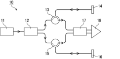
- FIG. 1 is a schematic diagram showing an example of a conventional optical coherence tomography (OCT) apparatus.
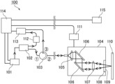
- FIG. 1 is a schematic diagram showing an example of an OCT apparatus of the present disclosure.
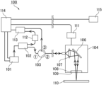
- FIG. 3 is a schematic diagram showing another example of the OCT apparatus of the present disclosure.
- an optical coherence tomography (OCT) apparatus using a Michelson interferometer as shown in FIG. 1 is commonly used.
- OCT optical coherence tomography
- light output from a light source 11 is split by a coupler 12 into a reference light that passes through an optical path that includes a circulator 13 and a reference mirror 14, and a sample light that passes through an optical path that includes a circulator 15 and a sample 16. occurs.
- the reference light and sample light are combined by a coupler 17, and an interference signal is detected by a photodetector 18.
- OCT devices used in the medical field are focused on taking tomographic images of very narrow areas such as the eyeballs from close range with high precision. There is a problem in that it is difficult to apply to fields where tomography is required.
- the present inventors have constructed an OCT apparatus in which both sample light and reference light pass through an objective lens, so that the light from the light source that passes through the objective lens is irradiated onto the sample at a wide angle. discovered that the above problem could be solved by constructing the reference surface with a light scattering body, and completed the OCT apparatus of the present disclosure.
- the present disclosure includes an objective lens that focuses light from a light source on a sample, and includes sample light that is reflected light from the sample and reflected light from a reference surface provided between the objective lens and the sample.
- An optical coherence tomography apparatus that performs tomography of the sample based on interference with a certain reference light, wherein both the sample light and the reference light pass through the objective lens, and the light source passes through the objective lens.
- Light is irradiated on the sample at a wide angle, and the reference plane provides an OCT device constituted by a light scatterer.
- both sample light which is reflected light from a sample to be imaged
- reference light which is reflected light from a reference surface
- the sample light and reference light are generated from light from a light source.
- Light from the light source passes through an objective lens included in the OCT apparatus of the present disclosure and is focused on the sample.
- the reflected light from the sample becomes sample light.
- a part of the light from the light source is reflected by a reference surface provided between the objective lens and the sample, and becomes reference light.
- both the sample light and the reference light are generated from light from the light source that passes through the objective lens.
- the difference in environment between the sample light path and the reference light path is reduced. This makes it possible to further reduce deviations in the obtained tomographic images.
- Wide-angle irradiation refers to irradiation in a range where the angle ⁇ between the light beam incident on the sample surface and the perpendicular to the sample surface is 0 degrees or more and 90 degrees or less.
- the angle ⁇ may be more than 0 degrees, preferably 1 degree or more, more preferably 2 degrees or more, and may be less than 90 degrees, preferably 30 degrees or less. , more preferably 15 degrees or less. Note that the irradiation may be performed over the entire range described above.
- the wide-angle irradiation method includes (i) a method in which the light from the light source is converged by a short focal length lens as an objective lens, and the resulting converged light is irradiated at a wide angle by a scanning mirror, or ( ii) A method of irradiating the sample with light from the light source using a wide-angle lens as an objective lens. Particularly preferred is method (i).
- the objective lens short focal length lens
- the objective lens short focal length lens
- the angle at which the light is irradiated onto the sample and the sample can be adjusted. The degree of freedom in adjusting the distance can be increased.
- the light from the light source can be irradiated onto the sample over a wide angle by changing the inclination of the mirror surface of the scanning mirror so that the angle ⁇ falls within the above-mentioned range. can.
- the light from the light source can be irradiated onto the sample at a wide angle by performing irradiation with a configuration in which the angle of view ⁇ determined by the method described below is 0 degrees or more and 90 degrees or less.
- the angle of view ⁇ may be more than 0 degrees, preferably 1 degree or more, more preferably 2 degrees or more, and may be less than 90 degrees, preferably 30 degrees or less. Preferably, it is more preferably 15 degrees or less.
- the above-mentioned angle of view ⁇ is determined from the value of tan ⁇ below when the diagonally opposite ends of the image sensor included in the OCT apparatus are connected at the center of the lens.
- the image sensor may be provided in a detector (detector (1)) to be described later, and may be a CCD image sensor or an InGaAs photodiode.
- the incident light flux sufficiently reaches the corner of the range that the objective lens can capture, and that optical performance can be ensured within this range. It is preferable that the deviation in optical imaging is 10% or less.
- the objective lens is a short focus lens or a wide angle lens.
- the short focus lens is a condenser lens that has a focal length of 50 mm or less when focused at infinity using light with a wavelength of 800 to 1750 nm.
- the focal length of the short focus lens is more preferably 45 mm or less, more preferably 1 mm or more, and more preferably 2 mm or more.
- the focal length can be measured according to JIS B 7094 (ISO 517).
- the short focal length lens has a variable focal position (condensing distance). Since the focal position is variable, the focal position can be changed without replacing the objective lens.
- An example of a short focal length lens whose focal position is variable is a collimating lens that can adjust the distance between the lens and the exit of the optical fiber.
- the short focus lens has a variable focal length. Since the focal length is variable, the focal length can be changed without replacing the objective lens.
- the short focus lens may be a collimating lens such as an achromatic fiber collimator.
- the above short focus lens can be particularly suitably used in the method (i) above.
- the wide-angle lens may have a focal length of 200 mm or less, preferably 100 mm or less, more preferably 50 mm or less, and 40 mm or less when focused at infinity using light with a wavelength of 800 to 1750 nm. It is more preferable that it is below. Moreover, it may be 1 mm or more, preferably 2 mm or more, and more preferably 8 mm or more.
- the focal length can be measured according to JIS B 7094 (ISO 517).
- the wide-angle lens preferably has a variable focal position (condensing distance). Since the focal position is variable, the focal position can be changed without replacing the objective lens.
- the wide-angle lens has a variable focal length. Since the focal length is variable, the focal length can be changed without replacing the objective lens.
- the wide-angle lens may be a wide-angle camera lens.
- the wide-angle lens described above can be particularly preferably used in the method (ii) above.
- the reference plane is provided between the objective lens and the sample.
- the reference plane may be provided perpendicular to the optical axis of the objective lens, but is not limited thereto.
- the reference surface needs to be a surface that reflects at least a part of the light from the light source, and is easy to configure so that the sample light and reference light pass through a common optical path. It is preferable that the surface transmits a part of the light and reflects a part of the light. In this aspect, the light transmitted through the reference surface is focused on the sample to generate sample light, while the light reflected by the reference surface becomes reference light.
- the reference surface is preferably a flat surface, more preferably a flat surface of the reference member, and even more preferably a surface of the reference member on the sample side. It is preferable that the reference member transmits part of the light from the light source and reflects part of the light.
- the reference surface is composed of a light scatterer.
- the reference member may also be composed of a light scattering body.
- the light from the light source may be obliquely incident on the reference plane depending on the position.
- the reference surface by configuring the reference surface with a light scattering body, it is possible to easily obtain reflected light along the same optical path as the incident light from light that is obliquely incident on the reference surface. This makes it possible to perform tomography over a wide area at once, and also to perform tomography of a distant object.
- the light scattering material may have a haze value of 5 to 95% in a wavelength range of 400 to 1750 nm.
- the haze value is preferably 10% or more, more preferably 15% or more, further preferably 90% or less, and more preferably 80% or less.
- the haze value can be measured using a haze meter in accordance with JIS R 3106 (ISO 9050), JIS K 7361-1 (ISO 13468-1), and JIS K 7136 (ISO 14782).
- the light scatterer may have a total light transmittance of 10 to 90% in a wavelength range of 400 to 1750 nm.
- the total light transmittance is preferably 15% or more, more preferably 20% or more, and preferably 80% or less, more preferably 70% or less.
- the total light transmittance can be measured using a haze meter in accordance with JIS R 3106 (ISO 9050), JIS K 7361-1 (ISO 13468-1), and JIS K 7136 (ISO 14782).
- the light scattering body may be anything as long as it scatters the light from the light source.
- Examples include glass or resin with fine irregularities on the surface, such as frosted glass, frosted glass, and Fresnel lenses; glass or resin that has light-scattering bubbles, particles, etc. inside.
- glass or resin having fine irregularities on the surface is preferable as the light scattering body.
- the shape of the reference member may be any shape as long as it has a flat surface, and may be plate-like, cylindrical, prismatic, etc., but preferably cylindrical. When it is cylindrical, it does not necessarily have to be a perfect cylinder. Furthermore, when the reference member further has a plane other than the reference plane, the reference plane and the other plane do not necessarily have to be parallel.
- the thickness of the reference member is preferably, for example, 0.01 to 50 mm.
- the above thickness is more preferably 0.1 mm or more, even more preferably 0.3 mm or more, particularly preferably 0.5 mm or more, and more preferably 30 mm or less, and 20 mm or less. It is more preferable that it is, and it is especially preferable that it is 10 mm or less.
- the thickness of both the thinnest part and the thickest part is within the said range.
- the reference member satisfies the following relational expression (1).
- nd represents the optical thickness of the reference member, and Z max represents the measurable distance.
- the optical thickness is the product of the refractive index and the actual (geometric) thickness of the reference member.
- the measurable distance is expressed by the following relational expression (2).
- the reference member satisfies the following relational expression (3).
- n represents the refractive index of the reference member.
- WD represents the working distance of the OCT device.
- nd and Z max are as described above.
- the working distance is the distance from the frontmost surface of the objective lens on the sample side to the sample when focusing.
- the thickness of the reference member is preferably thick within a range that satisfies relational expression (3), since the intensity of the ghost image based on the back reflection can be further reduced. Further, it is also preferable that the rear basal surface of the reference member be inclined with respect to the reference surface. The above-mentioned effect becomes particularly noticeable when an anti-alias filter (low-pass filter), which will be described later, is provided.
- an anti-alias filter low-pass filter
- the reference member satisfies the following relational expression (4).
- nd m ⁇ Z max (4) (In the formula, nd and Z max are as above.
- m represents an integer of 1 or more.)
- m is preferably an integer of 1 or more and 20 or less, and is also preferably an integer of 1 or more and 10 or less.
- the reference plane may be located at a distance of 5 mm to 5 m from the objective lens.
- the distance is preferably 10 mm or more, more preferably 20 mm or more, and preferably 2 m or less, and more preferably 1 m or less.
- the OCT apparatus of the present disclosure may include the reference surface (reference member) described above.
- the light source may be a low coherence light source, and is preferably a frequency scanning light source that scans while changing the frequency (wavelength) over time.
- the above-mentioned frequency scanning light source includes a wavelength swept laser using a wavelength sweeping filter (driving by a polygon mirror, driving by a galvano mirror, etc.), FDML laser, MEMS wavelength swept light source (MEMS VCSEL, external cavity type MEMS Fabry-Perot laser, etc.) , SGDBR laser, etc. can be used.
- the light emitted from the light source includes visible light and infrared light, with near-infrared light (NIR) being preferred.
- NIR near-infrared light
- As the light beam it is preferable to use a light beam with a wavelength of 800 to 2000 nm. Among these, from the viewpoint of stability of the light source and reliability of the sensor, light beams having a center wavelength of 940 ⁇ 50 nm, 1100 ⁇ 50 nm, 1310 ⁇ 50, 1550 ⁇ 100, or 1750 ⁇ 100 nm are more preferable.
- the OCT apparatus of the present disclosure may include the light source described above.
- the OCT apparatus of the present disclosure performs tomography of the sample based on interference between the sample light and the reference light.
- the above-mentioned interference may be of any type that allows both the sample light and the reference light to pass through the objective lens, but it is preferably Fizeau-type interference or Mireau-type interference, and Fizeau-type interference is preferred. It is more preferable that there be.
- Types of OCT that can be employed in the OCT apparatus of the present disclosure include time domain OCT (TD-OCT), Fourier domain OCT (FD-OCT), and the like.
- FD-OCT include spectral domain OCT (SD-OCT), frequency scanning OCT (Swept Source OCT: SS-OCT), and the like.
- SD-OCT spectral domain OCT
- SS-OCT frequency scanning OCT
- SS-OCT is preferable because it has high sensitivity and a deep measurable depth.
- the OCT apparatus of the present disclosure includes a probe having the objective lens described above. There may be one or more probes.
- the probe may or may not have the reference surface (or reference member), but preferably has the reference surface (or reference member). Moreover, it is more preferable that the probe further includes a collimator and a scanning mirror, which will be described later.
- the OCT apparatus of the present disclosure includes a plurality of the probes
- tomography at different positions can be performed in parallel using the plurality of probes.
- information based on light of different frequencies may be acquired from the plurality of probes.
- tomography at different depths can be performed in parallel using the plurality of probes.
- the probe may be arranged to be mechanically movable. According to this configuration, tomography can be performed while mechanically moving the probe, so that tomography of a large sample can be easily performed.
- the moving direction of the probe is not particularly limited and may be determined depending on the range to be tomographically imaged, but for example, it may be in a direction that intersects with the optical axis of the objective lens, in which the probe is emitted from the objective lens to the sample side. It may be in a direction that intersects the optical path of the light beam, it may be in a direction along the shape of the sample, it may be in a direction along the sample surface, or it may be in a direction substantially parallel to the sample surface. .
- the above configuration can be realized, for example, by disposing the probe in a moving mechanism that will be described later.
- the probe is connected to the OCT apparatus main body (casing) via an optical fiber.
- the light from the light source as well as the sample light and reference light are transmitted through the optical fiber.
- tomography can be performed by positioning the probe near the object by adjusting the length of the optical fiber. Since the light from the light source, the sample light, and the reference light are all transmitted through the optical fiber, even if the optical fiber is lengthened, there will be no difference in environment between the sample optical path and the reference optical path, and the obtained tomographic image will be The deviation is small. Furthermore, since it is a wired type using the optical fiber, high-resolution OCT measurement can be performed even on a photographic subject located far away from the main body.
- the length of the optical fiber is not particularly limited and can be determined depending on the location of the object to be photographed, but for example, it may be 1 m or more, preferably 3 m or more, and more preferably 5 m or more. Preferably, the length is more preferably 10 m or more. Further, the length may be 100 m or less, or may be 50 m or less.
- the OCT device main body preferably includes, for example, the light source, and more preferably includes a circulator, a detector, a DAQ device, an arithmetic device, etc., which will be described later.
- the OCT apparatus of the present disclosure further includes a collimator that converts the light from the light source into parallel light.
- the collimator is preferably provided on an optical path between the light source and the reference surface, and more preferably provided on an optical path between the light source and the objective lens.
- the objective lens described above preferably a short focus lens
- the OCT apparatus of the present disclosure further includes a scanning mirror that scans the light from the light source that is focused on the sample.
- the scanning mirror is preferably provided on an optical path between the light source and the objective lens, and more preferably on an optical path between the collimator and the objective lens. This aspect is particularly suitable when the objective lens is a wide-angle lens. It is also preferable that the scanning mirror is provided on an optical path between the objective lens and the reference surface. This aspect is particularly suitable when the objective lens is a short focus lens.
- Examples of the scanning mirror include a galvano mirror, a polygon mirror, and a MEMS mirror.
- a galvano mirror is preferable, a uniaxial or biaxial galvano mirror is more preferable, and a biaxial galvano mirror is even more preferable.
- the OCT apparatus of the present disclosure further includes a drive device for driving the scanning mirror.
- the OCT apparatus of the present disclosure further includes a detector that outputs light from the light source to the objective lens side, detects the sample light and reference light that have passed through the objective lens, and detects the sample light and reference light. It is preferable to include a circulator that outputs the output on the side. In this aspect, the sample light and reference light can be transmitted by one circulator. With this configuration, the device can be made smaller and costs can be reduced compared to the case where separate circulators are provided through which the sample light and reference light pass, as shown in FIG. You can also do it.
- the circulator preferably has three or more ports, more preferably three ports.
- the circulator is preferably provided on an optical path between the light source and the objective lens, and more preferably on the optical path between the light source and the collimator.
- light from the light source is input through a first port on the side of the light source and output through a second port on the side of the objective lens.
- the sample light and reference light that have passed through the objective lens are input from a second port and output from a third port on the detector side.
- the OCT apparatus of the present disclosure further includes a detector (also referred to as detector (1)) that detects the sample light and reference light. It is preferable that the detector (1) detects an interference signal caused by the sample light and the reference light. There may be one or more detectors (1).
- the detector (1) is a differential photodetector.
- the detector (1) may have the function of amplifying the signal. Further, an amplifier may be provided separately.
- the OCT apparatus of the present disclosure further includes a coupler (coupler) that splits the light from the light source into split light 1 used to generate the sample light and reference light, and split light 2 used to remove the DC component of the interference signal.
- a coupler (coupler) that splits the light from the light source into split light 1 used to generate the sample light and reference light, and split light 2 used to remove the DC component of the interference signal.
- (1)) is preferably provided.
- the coupler (1) is preferably provided on an optical path between the light source and the objective lens, and more preferably on the optical path between the light source and the circulator.
- the intensity ratio between the split light 1 and the split light 2 is preferably 90:10 to 99:1, more preferably 92:8 to 98:2. By dividing into such intensity ratios, the DC component can be effectively removed from the interference signal.
- the OCT apparatus of the present disclosure further includes a detector (also referred to as detector (2)) that detects the split light 2.
- detector (2) may be the same detector as the detector (1) described above, or may be a different detector.
- the OCT apparatus of the present disclosure further includes an attenuator that attenuates the split light 2.
- the attenuator is preferably a variable optical attenuator (VOA).
- VOA variable optical attenuator
- the attenuator is preferably provided on the optical path between the coupler (1) and the detector (2) that detects the split light 2.
- the OCT apparatus of the present disclosure may further include a polarization module that adjusts the polarization state of light from the light source.
- the polarizing module is preferably provided on an optical path between the light source and the objective lens, and more preferably on the optical path between the light source and the coupler (1).
- the OCT apparatus of the present disclosure includes a plurality of the probes, it is preferable to include a coupler (also referred to as coupler (2)) that splits the light from the light source into light sent to each probe.
- the coupler (2) is preferably provided on an optical path between the light source and the objective lens, and more preferably on the optical path between the circulator and the collimator.
- the OCT device of the present disclosure may include a modulator that modulates the frequency of light.
- the modulator include an acousto-optic (AO) modulator and an electro-optic (EO) modulator.
- AO acousto-optic
- EO electro-optic
- a plurality of the above modulators may be provided corresponding to each probe. According to this configuration, information based on light of different frequencies can be acquired from the plurality of probes, and tomography at different depths can be performed in parallel using the plurality of probes. Images corresponding to different depths obtained by the plurality of probes can also be encoded in the depth direction and displayed simultaneously on a display device to be described later.
- the modulator is preferably provided on an optical path between the light source and the objective lens, and more preferably provided on an optical path between the circulator and the collimator.
- the OCT apparatus of the present disclosure includes a plurality of the above probes, it is preferable that the OCT apparatus includes a coupler (also referred to as coupler (3)) that couples light from the plurality of probes.
- a coupler also referred to as coupler (3)
- the coupler (2) described above can also be used as coupler (3).
- the coupler (3) is preferably provided on an optical path between the light source and the objective lens, and more preferably on the optical path between the circulator and the collimator.
- the OCT apparatus of the present disclosure further includes a data acquisition (DAQ) device that collects interference signals caused by the sample light and reference light.
- the DAQ device includes an A/D converter.
- the DAQ device converts the collected interference signal into digital data.
- the DAQ device may be one or more.
- the OCT apparatus of the present disclosure further includes an anti-alias filter (also referred to as a low-pass filter) that attenuates unnecessary frequency components exceeding the measurable distance (Z max ).
- the anti-aliasing filter is preferably provided on an optical path between the detector (1) and the DAQ device.
- the OCT apparatus of the present disclosure further includes an arithmetic device that generates an optical coherence tomographic image based on interference signals of the sample light and reference light.
- the arithmetic device generates an optical coherence tomographic image by converting the interference signal into an image according to characteristics such as intensity.
- the OCT apparatus of the present disclosure further includes a display device that displays the obtained optical coherence tomographic image.
- the display device may be of a stationary type or a portable type, but a portable type is preferable because images can be checked at the shooting site.
- the connection with the arithmetic device may be wired or wireless. There may be one or more display devices.
- a frequency scanning light source 101 outputs light used for OCT.
- the frequency scanning light source 101 outputs a trigger signal every time frequency scanning starts.
- light is detected by a Mach-Zehnder interferometer, and a K clock signal for sampling at equal frequency intervals is output.
- the light output from the frequency scanning light source 101 is divided into split light 1 used to generate sample light and reference light and split light 2 used to remove the DC component of the interference signal at an intensity ratio of 95:5 in the coupler 102. It is divided into two parts.
- Split light 1 is input to port 1 of circulator 103, output from port 2, and transmitted to probe 104 through an optical fiber several meters long.
- the divided light 1 is converted into parallel light by a collimator 105, then reflected by a galvano mirror 106, and enters an objective lens 107, which is a wide-angle lens.
- the galvano mirror 106 is driven by the galvano mirror driver 111 and scans the parallel light in the XY directions perpendicular to the optical axis.
- the parallel light incident on the objective lens 107 passes through the reference member 108 made of a light scattering body, is focused on the sample 110 to be photographed, is reflected on the sample surface, and enters the objective lens 107 as sample light. .
- a part of the parallel light that has entered the objective lens 107 is reflected on a reference surface 109 provided in the reference member 108 and enters the objective lens 107 as reference light.
- the sample light and reference light incident on the objective lens 107 pass through the galvanometer mirror 106 and the collimator 105, and then enter the port 2 of the circulator 103 through an optical fiber, are output from the port 3, and then enter the differential light detection amplifier 113. is input.
- the differential optical detection amplifier 113 detects and amplifies an interference signal based on interference between the sample light and the reference light.
- the split light 2 split by the coupler 102 is attenuated by a variable optical attenuator 112 and then input to a differential optical detection amplifier 113 .
- the differential optical detection amplifier 113 uses the signal of the split light 2 to remove the DC component contained in the interference signal.
- the DC component is removed by the differential photodetection amplifier 113, and the amplified interference signal is collected by a DAQ device (A/D converter) included in the PC 114 and converted into digital data. Collection of the interference signal is started by a trigger signal emitted by the frequency scanning light source 101 and is performed in synchronization with the K clock signal.
- an anti-alias filter (not shown) is provided between the differential optical detection amplifier 113 and the DAQ device to attenuate unnecessary frequency components beyond the measurable distance (Z max ).
- the computing device included in the PC 114 generates an optical coherence tomographic image of the sample 110 based on the interference signal converted by the DAQ device, and displays it on the mobile display 115.
- the OCT apparatus of the present disclosure is not limited to this.
- light emitted from the objective lens 107 which is a short focus lens, is reflected by the galvanometer mirror 106, passes through the reference member 108, and is irradiated onto the sample 110.
- the sample 110 can be irradiated with light over a wide angle.
- the sample light from the sample surface is reflected by the galvanometer mirror 106 and enters the objective lens 107 .
- a part of the light emitted from the objective lens 107 is reflected on a reference surface 109 provided in the reference member 108 and enters the objective lens 107 as reference light.
- the other configurations are as described in FIG. 2.
- the probe and the OCT apparatus main body (casing) are connected via an optical fiber with a length of 3 m or more, and the atmosphere around the probe equipped with the objective lens and the OCT apparatus main body (casing)
- the temperature difference between the body and the surrounding atmosphere is 1° C. or more, it is preferable that the deviation of the obtained optical coherence tomographic image is 100 ⁇ m or less.
- the object to be imaged may be located far away from the main body of the OCT apparatus, outdoors, or in a facility with high or low temperatures.
- the length of the optical fiber in the above embodiment is preferably 3 m or more, more preferably 5 m or more, and even more preferably 10 m or more. Further, the length may be 100 m or less, or may be 50 m or less.
- the temperature difference in the atmosphere in the above embodiment is preferably 1°C or more, more preferably 5°C or more, and even more preferably 10°C or more. Moreover, it is preferable that the said temperature difference is 50 degreeC or less.
- the deviation of the optical coherence tomographic image is preferably 100 ⁇ m or less, more preferably 50 ⁇ m or less, and particularly preferably 30 ⁇ m or less.
- the above ⁇ Z is the optical distance shift. When the optical fiber material is quartz glass, the wavelength of light is 1.3 ⁇ m, and the temperature is around room temperature, dn/dT is approximately 1.9 ⁇ 10 ⁇ 5 (1/° C.).
- the temperature difference between the atmosphere around the probe and the atmosphere around the OCT device main body is almost directly reflected in the temperature difference ⁇ t in the optical path.
- the deviation ⁇ Z of the obtained tomographic images is large.
- the temperature difference ⁇ t in the optical path is extremely small, so ⁇ Z is also extremely small.
- the OCT device of the present disclosure has a horizontal area of 0.1 to 100 cm in length and 0.1 to 100 cm in width that can be imaged with a resolution of 10 ⁇ m or more per tomography performed under the following conditions. It is preferable that This makes it possible to perform accurate tomography over a wide area at once (even when using other light sources).
- AXSUN high-speed wavelength swept light source center wavelength: 1310 nm, sweep width: 100 nm, A-scan rate: 50 kHz, output: 25 mW, coherence length: 12 mm
- the present disclosure also provides an OCT system including the above-described OCT device of the present disclosure and a movement mechanism that mechanically moves the probe included in the OCT device.
- OCT system of the present disclosure tomography can be performed while mechanically moving the probe, so tomography of a large sample can be easily performed.
- the moving direction of the probe is not particularly limited and may be determined depending on the range to be tomographically imaged, but for example, it may be in a direction that intersects with the optical axis of the objective lens, in which the probe is emitted from the objective lens to the sample side.
- the moving mechanism may be a mechanism that automatically moves the probe.
- Optical coherence tomography of a sample can be performed using the OCT device or OCT system of the present disclosure.
- the present disclosure also provides an OCT method using the OCT device or OCT system of the present disclosure described above. With the OCT method of the present disclosure, it is possible to perform tomography of a wide area at once and tomography of a distant target. Further, even when tomography is performed at a location away from the OCT apparatus main body, there is no difference in environment between the sample optical path and the reference optical path, so the deviation of the obtained tomographic images is small.
- tomography can be performed with the distance between the objective lens and the sample set to 2 cm or more and less than 2 m.
- the distance between the objective lens and the sample may be more than 3 cm, 5 cm or more, 10 cm or more, or 20 cm or more. Since the OCT method of the present disclosure uses the OCT apparatus or OCT system of the present disclosure, tomography can be performed even on a sample located far away as described above.
- tomography can be performed with the distance between the reference plane and the sample being 0 to 50 mm.
- the distance between the reference surface and the sample is preferably 0.01 mm or more, more preferably 0.1 mm or more, and preferably 30 mm or less, more preferably 10 mm or less. .
- tomography may be performed while mechanically moving a probe having the objective lens.
- tomography can be performed while mechanically moving the probe, so that tomography of a large sample can be easily performed.
- the moving direction of the probe is not particularly limited and may be determined depending on the range to be tomographically imaged, but for example, it may be in a direction that intersects with the optical axis of the objective lens, in which the probe is emitted from the objective lens to the sample side. It may be in a direction that intersects the optical path of the light beam, it may be in a direction along the shape of the sample, it may be in a direction along the sample surface, or it may be in a direction substantially parallel to the sample surface. .
- the probe may be moved by being disposed on the moving mechanism described above.
- tomography may be performed while mechanically moving the sample.
- the moving direction of the sample is not particularly limited and may be determined depending on the range to be tomographically imaged, but for example, it may be a direction that intersects the optical axis of the objective lens, and the direction in which the sample is emitted from the objective lens to the sample side may be determined. It may be in a direction that intersects the optical path of the light beam, it may be in a direction along the shape of the sample, it may be in a direction along the sample surface, or it may be in a direction substantially parallel to the sample surface.
- the probe may be fixed or movable during tomography.
- a plurality of probes each having the objective lens described above may be used to perform tomography using light of a plurality of different frequencies.
- tomography at different depths can be performed in parallel using the plurality of probes.
- information based on light of different frequencies may be acquired from the plurality of probes, and tomography may be performed based on the information.
- tomography may be performed from a plurality of different directions using a plurality of probes each having the objective lens described above. According to this configuration, tomography of one sample can be simultaneously performed from different directions using the plurality of probes.
- the present disclosure also provides an inspection method for inspecting the internal state of a sample based on image data obtained by tomographically photographing the sample using the OCT method of the present disclosure described above.
- the inspection method of the present disclosure it is possible to inspect the internal state of a sample over a wide range at once, and to inspect the internal state of a sample at a remote location. Furthermore, even when testing is performed at a location away from the OCT apparatus main body, there is no difference in environment between the sample optical path and the reference optical path, so deviations in the obtained tomographic images are small and highly accurate testing can be performed.
- the inspection may be an inspection for defects inside the sample.
- Examples of the above-mentioned defects include foreign matter, voids, and the like.
- the OCT device, OCT system, OCT method, and inspection method of the present disclosure can be suitably used in all fields where OCT can be used. As mentioned above, it is possible to perform tomography of a wide area at once and tomography of a distant target, and furthermore, even when tomography is performed at a place far from the OCT device itself, there are advantages. Since the deviation of the resulting tomographic images is small, it can be suitably used particularly in the industrial field.
- the OCT device, OCT system, OCT method, or inspection method of the present disclosure can also be incorporated into a production line for industrial products.
- OCT device 11 light source 12, 17: coupler 13, 15: circulator 14: reference mirror 16: sample 18: photodetector 100: OCT device 101: frequency scanning light source 102: coupler 103: circulator 104: probe 105: collimator 106: Galvanometer mirror 107: Objective lens 108: Reference member 109: Reference surface 110: Sample 111: Galvanometer mirror driver 112: Variable optical attenuator 113: Differential optical detection amplifier 114: PC 115: Mobile display
Abstract
L'invention concerne un appareil de tomographie par cohérence optique ou analogue, permettant d'effectuer une tomographie sur une large plage en une seule fois, ainsi qu'une tomographie d'un objet éloigné. L'appareil de tomographie par cohérence optique comprend une lentille d'objectif qui condense la lumière d'une source lumineuse sur un échantillon et effectue la tomographie de l'échantillon sur la base de l'interférence de la lumière de l'échantillon, qui est la lumière réfléchie par l'échantillon, et de la lumière de référence, qui est la lumière réfléchie par une surface de référence située entre la lentille d'objectif et l'échantillon, la lumière de l'échantillon et la lumière de référence traversant toutes deux la lentille d'objectif, l'échantillon étant irradié selon un grand angle par la lumière de la source lumineuse qui a traversé la lentille d'objectif, et la surface de référence étant configurée comme un diffuseur de lumière.
Applications Claiming Priority (2)
| Application Number | Priority Date | Filing Date | Title |
|---|---|---|---|
| JP2022-055706 | 2022-03-30 | ||
| JP2022055706 | 2022-03-30 |
Publications (1)
| Publication Number | Publication Date |
|---|---|
| WO2023190865A1 true WO2023190865A1 (fr) | 2023-10-05 |
Family
ID=88202886
Family Applications (1)
| Application Number | Title | Priority Date | Filing Date |
|---|---|---|---|
| PCT/JP2023/013172 WO2023190865A1 (fr) | 2022-03-30 | 2023-03-30 | Appareil, système de tomographie par cohérence optique et procédé de tomographie par cohérence optique, et procédé d'inspection |
Country Status (2)
| Country | Link |
|---|---|
| TW (1) | TW202407319A (fr) |
| WO (1) | WO2023190865A1 (fr) |
Citations (3)
| Publication number | Priority date | Publication date | Assignee | Title |
|---|---|---|---|---|
| US20040075843A1 (en) * | 2002-07-01 | 2004-04-22 | Marron Joseph C. | Interferometer system of compact configuration |
| JP2004191114A (ja) * | 2002-12-10 | 2004-07-08 | Naohiro Tanno | 光コヒーレンストモグラフィーにおける光干渉計一体駆動による検知点走査方法及び光コヒーレンストモグラフィー装置 |
| JP2015092158A (ja) * | 2013-11-01 | 2015-05-14 | 株式会社トーメーコーポレーション | マルチチャンネル光コヒーレンストモグラフィ |
-
2023
- 2023-03-30 WO PCT/JP2023/013172 patent/WO2023190865A1/fr unknown
- 2023-03-30 TW TW112112345A patent/TW202407319A/zh unknown
Patent Citations (3)
| Publication number | Priority date | Publication date | Assignee | Title |
|---|---|---|---|---|
| US20040075843A1 (en) * | 2002-07-01 | 2004-04-22 | Marron Joseph C. | Interferometer system of compact configuration |
| JP2004191114A (ja) * | 2002-12-10 | 2004-07-08 | Naohiro Tanno | 光コヒーレンストモグラフィーにおける光干渉計一体駆動による検知点走査方法及び光コヒーレンストモグラフィー装置 |
| JP2015092158A (ja) * | 2013-11-01 | 2015-05-14 | 株式会社トーメーコーポレーション | マルチチャンネル光コヒーレンストモグラフィ |
Also Published As
| Publication number | Publication date |
|---|---|
| TW202407319A (zh) | 2024-02-16 |
Similar Documents
| Publication | Publication Date | Title |
|---|---|---|
| US6900943B2 (en) | Optical amplification in coherent optical frequency modulated continuous wave reflectometry | |
| US9820645B2 (en) | Ophthalmologic apparatus | |
| CA2421113C (fr) | Amplification optique en reflectometrie de coherence | |
| Pelivanov et al. | NDT of fiber-reinforced composites with a new fiber-optic pump–probe laser-ultrasound system | |
| EP3250956B1 (fr) | Système de microscopie avec réglage de mise au point automatique par interférométrie à faible cohérence | |
| KR101264671B1 (ko) | 광 간섭 계측 방법 및 광 간섭 계측 장치 | |
| JP4344829B2 (ja) | 偏光感受光画像計測装置 | |
| JP2004518125A (ja) | 組成分析 | |
| US20110222070A1 (en) | Optical Tomographic Image Forming Method | |
| GB2407155A (en) | Spectral interferometry method and apparatus | |
| JP2009133630A (ja) | 光コネクタおよびこれを用いる光断層画像化装置 | |
| WO2013091584A1 (fr) | Procédé et un dispositif de détection de défauts au sein d'une matrice | |
| RU2654379C1 (ru) | Мгновенная оптическая когерентная томография во временной области | |
| US20140213897A1 (en) | Combined Reflectance Confocal Microscopy-Optical Coherence Tomography System for Imaging of Biological Tissue | |
| Martell et al. | Multimodal imaging with spectral-domain optical coherence tomography and photoacoustic remote sensing microscopy | |
| WO2017209079A1 (fr) | Dispositif d'observation et procédé d'observation | |
| WO2023190865A1 (fr) | Appareil, système de tomographie par cohérence optique et procédé de tomographie par cohérence optique, et procédé d'inspection | |
| WO2022065305A1 (fr) | Dispositif de tomographie par cohérence optique et procédé de tomographie par cohérence optique | |
| CN110169758B (zh) | 一种全光的光声内窥成像装置及方法 | |
| EP2565625A1 (fr) | Système de mesure optique et procédé de fonctionnement d'un système de mesure optique | |
| US20240133674A1 (en) | High-resolution handheld oct imaging system | |
| WO2012157710A1 (fr) | Appareil d'acquisition d'images tomographiques optiques | |
| JP6723835B2 (ja) | 光干渉断層撮像装置 | |
| JP2774945B2 (ja) | 反射光測定装置 | |
| Adie | Enhancement of contrast in optical coherence tomography: new modes, methods and technology |
Legal Events
| Date | Code | Title | Description |
|---|---|---|---|
| 121 | Ep: the epo has been informed by wipo that ep was designated in this application |
Ref document number: 23780873 Country of ref document: EP Kind code of ref document: A1 |