WO2023162405A1 - Moving device and unmanned flying device - Google Patents
Moving device and unmanned flying device Download PDFInfo
- Publication number
- WO2023162405A1 WO2023162405A1 PCT/JP2022/045446 JP2022045446W WO2023162405A1 WO 2023162405 A1 WO2023162405 A1 WO 2023162405A1 JP 2022045446 W JP2022045446 W JP 2022045446W WO 2023162405 A1 WO2023162405 A1 WO 2023162405A1
- Authority
- WO
- WIPO (PCT)
- Prior art keywords
- drone
- landing
- engaging portion
- leveling table
- control device
- Prior art date
Links
- 239000012530 fluid Substances 0.000 claims description 62
- 238000003384 imaging method Methods 0.000 claims description 36
- 238000001514 detection method Methods 0.000 claims description 25
- 230000005540 biological transmission Effects 0.000 description 26
- 238000004891 communication Methods 0.000 description 22
- 238000010586 diagram Methods 0.000 description 21
- XLYOFNOQVPJJNP-UHFFFAOYSA-N water Substances O XLYOFNOQVPJJNP-UHFFFAOYSA-N 0.000 description 19
- 238000004140 cleaning Methods 0.000 description 16
- 239000007788 liquid Substances 0.000 description 15
- 239000000446 fuel Substances 0.000 description 8
- 239000001257 hydrogen Substances 0.000 description 8
- 229910052739 hydrogen Inorganic materials 0.000 description 8
- 238000012856 packing Methods 0.000 description 8
- 230000007246 mechanism Effects 0.000 description 7
- UFHFLCQGNIYNRP-UHFFFAOYSA-N Hydrogen Chemical compound [H][H] UFHFLCQGNIYNRP-UHFFFAOYSA-N 0.000 description 6
- 239000002828 fuel tank Substances 0.000 description 5
- 238000007600 charging Methods 0.000 description 4
- 239000007789 gas Substances 0.000 description 4
- 238000012545 processing Methods 0.000 description 4
- HBBGRARXTFLTSG-UHFFFAOYSA-N Lithium ion Chemical compound [Li+] HBBGRARXTFLTSG-UHFFFAOYSA-N 0.000 description 3
- 238000010276 construction Methods 0.000 description 3
- 229910001416 lithium ion Inorganic materials 0.000 description 3
- 238000000034 method Methods 0.000 description 3
- QGZKDVFQNNGYKY-UHFFFAOYSA-N Ammonia Chemical compound N QGZKDVFQNNGYKY-UHFFFAOYSA-N 0.000 description 2
- WHXSMMKQMYFTQS-UHFFFAOYSA-N Lithium Chemical compound [Li] WHXSMMKQMYFTQS-UHFFFAOYSA-N 0.000 description 2
- 230000001133 acceleration Effects 0.000 description 2
- 239000003905 agrochemical Substances 0.000 description 2
- QVGXLLKOCUKJST-UHFFFAOYSA-N atomic oxygen Chemical compound [O] QVGXLLKOCUKJST-UHFFFAOYSA-N 0.000 description 2
- 230000008859 change Effects 0.000 description 2
- 230000003028 elevating effect Effects 0.000 description 2
- 229910052744 lithium Inorganic materials 0.000 description 2
- 239000000463 material Substances 0.000 description 2
- 239000001301 oxygen Substances 0.000 description 2
- 229910052760 oxygen Inorganic materials 0.000 description 2
- 229920000642 polymer Polymers 0.000 description 2
- 239000007921 spray Substances 0.000 description 2
- RZVHIXYEVGDQDX-UHFFFAOYSA-N 9,10-anthraquinone Chemical compound C1=CC=C2C(=O)C3=CC=CC=C3C(=O)C2=C1 RZVHIXYEVGDQDX-UHFFFAOYSA-N 0.000 description 1
- 229910021529 ammonia Inorganic materials 0.000 description 1
- 238000013459 approach Methods 0.000 description 1
- OJIJEKBXJYRIBZ-UHFFFAOYSA-N cadmium nickel Chemical compound [Ni].[Cd] OJIJEKBXJYRIBZ-UHFFFAOYSA-N 0.000 description 1
- 238000002485 combustion reaction Methods 0.000 description 1
- 238000010277 constant-current charging Methods 0.000 description 1
- 230000008602 contraction Effects 0.000 description 1
- 239000012050 conventional carrier Substances 0.000 description 1
- 230000007423 decrease Effects 0.000 description 1
- 238000007599 discharging Methods 0.000 description 1
- 239000003651 drinking water Substances 0.000 description 1
- 235000020188 drinking water Nutrition 0.000 description 1
- 239000000428 dust Substances 0.000 description 1
- 230000005611 electricity Effects 0.000 description 1
- 238000003487 electrochemical reaction Methods 0.000 description 1
- 230000005674 electromagnetic induction Effects 0.000 description 1
- 230000006870 function Effects 0.000 description 1
- 150000002431 hydrogen Chemical class 0.000 description 1
- 238000001646 magnetic resonance method Methods 0.000 description 1
- 238000012986 modification Methods 0.000 description 1
- 230000004048 modification Effects 0.000 description 1
- 230000008569 process Effects 0.000 description 1
- 230000004044 response Effects 0.000 description 1
- 238000005507 spraying Methods 0.000 description 1
- 239000000126 substance Substances 0.000 description 1
Images


Classifications
-
- B—PERFORMING OPERATIONS; TRANSPORTING
- B64—AIRCRAFT; AVIATION; COSMONAUTICS
- B64U—UNMANNED AERIAL VEHICLES [UAV]; EQUIPMENT THEREFOR
- B64U70/00—Launching, take-off or landing arrangements
- B64U70/90—Launching from or landing on platforms
- B64U70/92—Portable platforms
- B64U70/93—Portable platforms for use on a land or nautical vehicle
-
- B—PERFORMING OPERATIONS; TRANSPORTING
- B64—AIRCRAFT; AVIATION; COSMONAUTICS
- B64U—UNMANNED AERIAL VEHICLES [UAV]; EQUIPMENT THEREFOR
- B64U80/00—Transport or storage specially adapted for UAVs
- B64U80/20—Transport or storage specially adapted for UAVs with arrangements for servicing the UAV
- B64U80/25—Transport or storage specially adapted for UAVs with arrangements for servicing the UAV for recharging batteries; for refuelling
Definitions
- the present invention relates to a mobile device and an unmanned flying device, and more particularly to a mobile device that facilitates takeoff and landing of an unmanned flying device and an unmanned flying device that is space efficient.
- Patent Document 1 discloses that an unmanned flying object is charged at the take-off/landing port.
- Patent Document 1 does not take into consideration that the work machine is used on a slope, and if the takeoff/landing port is sloped, there is a risk that the unmanned air vehicle will not be able to take off and land. Also, Patent Literature 1 does not disclose supplying fluid to an unmanned aerial vehicle.
- a second object of the present invention is to provide an unmanned flying device with good space efficiency even when a power receiving device and a fluidic device are provided.
- a mobile device comprises a main unit that travels by a traveling device, a takeoff and landing unit provided in the main unit for taking off and landing of an unmanned flying object, and a takeoff and landing unit provided in the takeoff and landing unit for adjusting an amount of inclination with respect to a vertical axis.
- An unmanned flying device comprises a flight device having a propeller; a second engaging portion that engages with a first engaging portion provided on the landing portion when landing on the landing portion; A power receiving device provided outside the second engaging portion, and a fluid device provided inside the second engaging portion.
- the take-off/landing section is provided with a leveling table capable of adjusting the amount of inclination with respect to the vertical axis, it is possible to realize a mobile device that facilitates take-off and landing of the unmanned air vehicle.
- the power receiving device is provided outside the second engaging portion, and the fluidic device is provided inside the second engaging portion, thereby realizing an unmanned flying device with good space efficiency. can do.
- FIG. 4 is a schematic diagram showing a state in which the transport device is on a slope and the drive shaft is driven;
- FIG. 4A is a diagram showing how the drone lands on the take-off and landing section,
- FIG. 4A is a diagram showing the drone being obliquely above the table section, and
- FIG. 4B is a diagram showing the drone being above the table section.
- FIG. 4(c) is a diagram showing how the tapered portion of the second engaging portion contacts the packing, and FIG. 4(d) shows how the power transmitting electrode and the power receiving electrode come into contact.
- FIG. 4E is a diagram showing how the legs of the drone are held by the holding part. 4 is a flow chart executed by a control device;
- FIG. 5 is a schematic diagram of a hydraulic excavator representing the second embodiment;
- FIG. 10 is a block diagram of main parts of a hydraulic excavator and a drone according to the second embodiment;
- FIG. 11 is a schematic diagram of a hydraulic excavator representing the third embodiment;
- a construction machine according to an embodiment of the present invention will be described in detail below based on the attached drawings.
- the present invention is not limited by the embodiments described below.
- the transport device 1 that supports a UAV (Unmanned Aerial Vehicle, hereinafter referred to as a drone 100), which is an unmanned aerial vehicle that flies over a slope.
- UAV Unmanned Aerial Vehicle
- the vertical direction is defined as the Z direction
- the biaxial directions orthogonal to each other in the horizontal plane are defined as the X direction and the Y direction.
- FIG. 1A and 1B are schematic diagrams of a conveying apparatus 1 representing the first embodiment
- FIG. 1A is a top view
- FIG. 1B is a front view
- FIG. 1C is a side view
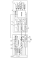
- FIG. 2 is a block diagram of main parts of the transport device 1 and the drone 100 of the first embodiment.
- FIG. 1(b) is shown as a cross section taken along the line AA of FIG. 1(a).
- the conveying apparatus 1 of the first embodiment is of an automatic operation type or a remote operation type without a driver's seat.
- the transport device 1 includes a traveling device 10, a base portion 20, a main body portion 30, a leveling portion 40, a power transmission device 50, a fluid supply portion 60, an imaging device 55, and a first GNSS 65 (Global Navigation Satellite System). , a first communication device 66 , a first memory 67 and a control device 70 .
- a traveling device 10 a base portion 20, a main body portion 30, a leveling portion 40, a power transmission device 50, a fluid supply portion 60, an imaging device 55, and a first GNSS 65 (Global Navigation Satellite System).
- GNSS 65 Global Navigation Satellite System
- the traveling device 10 moves the conveying device 1, and has driving wheels 11, driven wheels 12, crawler belts 13, and supports .
- the travel device 10 also includes a travel motor 15 , a central frame 16 , a pair of side frames 17 , a pair of link mechanisms 18 , and a coupler 19 .
- the travel device 10 is detachable from the base portion 20 by a coupler 19 (details will be described later).
- one driving wheel 11 and two driven wheels 12 form a triangular shape.
- a plurality of driven wheels smaller than the two driven wheels 12 are provided between the two driven wheels 12 .
- the crawler belt 13 is wound around one drive wheel 11 and two driven wheels 12 .
- the support 14 rotatably supports the drive wheel 11 and the driven wheel 12 . Since there are four triangular crawler belt-type traveling bodies in the first embodiment, the conveying apparatus 1 can travel stably even on rough terrain.
- the traveling device 10 an endless track in which crawler belts are wound around the front wheels and the rear wheels may be used.
- the traveling motor 15 (see FIG. 2) employs an in-wheel motor that transmits the driving force to the driving wheels 11 on the rear side of the driving wheels 11 .
- the rotating shaft of the in-wheel motor is connected to the rotating shaft of the driving wheel 11 , and the rotating driving force of the in-wheel motor rotates the driving wheel 11 , thereby transmitting the driving force to the crawler belt 13 .
- a motor different from the in-wheel motor may be employed as the traveling motor 15 .
- the center frame 16 is a frame positioned between two drive wheels 11 spaced apart in the Y direction, and is connected to a pair of side frames 17 via a pair of link mechanisms 18 .
- the central frame 16 is provided with a coupler 19 for connecting with the base portion 20 on its upper surface.
- a pair of side frames 17 are frames connected to the respective drive wheels 11 via bearings (not shown).
- the pair of link mechanisms 18 has a Z-shape or an inverted Z-shape, and includes a pair of connection members 18a connected at one end to the pair of side frames 17 and at the other end to the central frame 16, and at one end to the center frame 16. It has an actuator 18b connected to the connection member 18a on the side of the central frame 16 and having the other end connected to the connection member 18a on the side frame 17 side. It should be noted that two pairs of connection members 18a are provided spaced apart in the Z direction.
- the actuator 18b is provided at an angle, and expands and contracts to drive the pair of side frames 17 in the Z direction and the Y direction.
- Actuator 18b moves drive wheel 11, driven wheel 12, and crawler belt 13 in the Z and Y directions via a pair of side frames 17. As shown in FIG. Thereby, the travel device 10 can change the size in the Z direction and the Y direction.
- a hydraulic jack or an electric jack can be used as the actuator 18b, but the actuator 18b is not limited to this.
- the coupler 19 has a V-shaped notch, and four of them are provided on the upper surface of the base portion 20.
- the coupler 19 may be one, and the number thereof can be set arbitrarily.
- the coupler 19 connects the travel device 10 and the base portion 20 by engaging a pin (not shown) extending in the -Z direction provided on the lower surface of the base portion 20 and a V-shaped notch. ing. Further, the coupler 19 releases the connection between the travel device 10 and the base portion 20 by releasing the engagement with the pin.
- the connection structure between the coupler 19 and the pin is disclosed, for example, in Japanese Patent Application Laid-Open No. 2000-6856.
- the attachment and detachment of the coupler 19 and the pin may be performed by an electromagnet.
- the base part 20 is a rectangular member, the main body part 30 is placed on the upper surface, and the foldable legs 21 are provided on the lower surface.
- the leg portion 21 is a member that allows the base portion 20 to stand on its own before and after attachment/detachment to/from the travel device 10 .
- two leg portions 21 are provided on the base portion 20, but the number can be set arbitrarily.
- the shape of the base portion 20 is not limited to a rectangular shape, and may be an arbitrary shape such as an elliptical shape.
- the base portion 20 can change its position in the Z direction by driving the actuator 18b.
- the body portion 30 is fixed on the upper surface of the base portion 20, and includes a battery 31 that supplies electric power to electrical components such as the travel motor 15 and the actuator 18b, a leveling motor 32 that drives the leveling portion 40, A container 33 for storing fluid and a pump 34 capable of discharging this fluid to the drone 100 are housed inside.
- the battery 31 is a secondary battery that can be repeatedly charged and discharged, and a lithium ion secondary battery, a lithium polymer secondary battery, or the like can be used.
- the battery 31 can be charged by a constant-current and constant-voltage receiving method in the case of a lithium-ion secondary battery, and can be charged by constant-current charging in the case of a nickel-hydrogen secondary battery or a nickel-cadmium secondary battery. Although part of the illustration is omitted in the block diagram of FIG.
- the leveling motor 32 is a motor for independently driving three drive shafts 41, which constitute the leveling section 40, along the Z direction.
- three DC motors are used as the leveling motors 32, but the number of DC motors is not limited to this.
- the leveling motor 32 is driven by electric power supplied from the battery 31 .
- the container 33 is a container for storing fluids such as liquids and gases, and supplies liquids such as agricultural chemicals, cleaning liquids, chemical solutions, pure water, and drinking water in the first embodiment. Note that when the drone flies with gaseous fuel, the gaseous fuel (hydrogen, oxygen, etc.) may be stored in the container 33 .
- the gaseous fuel hydrogen, oxygen, etc.
- the pump 34 is a pump that supplies the fluid stored in the container 33 to the drone 100 via the fluid supply unit 60 described later.
- the pump 34 may be a direct current pump or a direct current electromagnetic motor using an electromagnet instead of a motor. It should be noted that the pump 34 is driven by power supplied from the battery 31 .
- the leveling section 40 includes three drive shafts 41, a table section 42, an attitude detection section 43, a holding section 44, a spring 45, and an opening section 46.
- the drone 100 takes off and lands. It functions as a take-off and landing part.
- the three drive shafts 41 are arranged so that the intervals between the drive shafts 41 are equal, one end is connected to the main body portion 30 side, and the other end is connected to the table portion 42 .
- the three drive shafts 41 are driven along the Z direction by the leveling motor 32 . That is, the table portion 42 can adjust the amount of inclination with respect to the vertical axis.
- FIG. 3 is a schematic diagram showing a state in which the transport device 1 is on a slope and the drive shaft 41 is driven.
- the table section 42 can be leveled. Therefore, the drone 100 can easily take off and land on the table section 42 .
- the table section 42 is provided on the upper surface side (+Z side) of the main body section 30 and has a size that allows the drone 100 to take off and land.
- one drone 100 lands on the table section 42, but it may be sized so that two or more drones 100 can take off and land.
- one leveling unit 40 may be provided, or a plurality of leveling units may be provided according to the number of drones 100 .
- the shape of the table portion 42 is circular in the first embodiment, it may be rectangular.
- the posture detection unit 43 is provided on the top surface or the bottom surface of the table unit 42 and detects the posture of the table unit 42 .
- the posture detection unit 43 an inclinometer, a spirit level, or the like can be used.
- the aforementioned drive shaft 41 is driven based on the detection result of the attitude detection section 43 .
- the holding section 44 engages with a leg section 109 provided on the drone 100 to hold the drone 100 on the table section 42 .
- the holding portion 44 is provided in the table portion 42 and is a rectangular groove that can be engaged with the leg portion 109 .
- the shape of the groove can be any shape according to the shape of the leg portion 109 .
- the holding portion 44 may be a lock mechanism that mechanically or electromagnetically locks the leg portion 109 instead of the groove.
- the spring 45 is an elastic member, one end of which is connected to the table portion 42 and the other end of which is connected to the power transmission device 50 (first engaging portion 51 described later).
- the spring 45 is elastically deformed so as to contract under the weight of the drone 100 when the drone 100 lands on the table section 42 . At this time, the power transmission device 50 is held by the table portion 42 .
- the opening 46 is a through hole provided in the table portion 42 .
- the opening 46 is provided in the center of the table portion 42 and serves as a route for routing the wiring of the power transmission device 50 between the leveling portion 40 and the power transmission device 50 . Further, the opening 46 serves as a path for routing a supply pipe 61 (to be described later) between the leveling section 40 and the fluid supply section 60 .
- the power transmission device 50 (see FIG. 4) is provided on the upper surface side (+Z side) of the table portion 42 via the spring 45 .
- the power transmission device 50 supplies power to a power reception device 103 provided in the drone 100 , which will be described later.
- the power transmission device 50 has a first engaging portion 51, a power transmission electrode 52, and a switch (not shown).
- the first engaging portion 51 is capable of engaging with a second engaging portion 111 of the drone 100, which will be described later, and has a tapered opening that decreases in diameter toward the table portion 42 side ( ⁇ Z side). are doing.
- the power transmission electrode 52 is provided on this tapered portion, and power is supplied by contacting the power receiving electrode 112 provided on the tapered portion of the power receiving device 103 .
- the power transmission electrode 52 and the battery 31 are connected by wiring passing through the opening 46 .
- Wireless power feeding may be employed for power feeding by the power transmitting device 50 and the power receiving device 103 .
- Wireless power supply supplies electric power in a non-contact manner, and magnetic resonance methods, electromagnetic induction methods, and the like are known.
- a switch (not shown) is an on/off switch for determining whether power is supplied to the power receiving apparatus 103 by the power transmitting apparatus 50 .
- the fluid supply unit 60 (see FIG. 4) supplies the fluid from the pump 34 to the drone 100.
- the fluid supply section 60 has a supply pipe 61 , a joint 62 and a packing 63 .
- the supply pipe 61 is provided so that one end is connected to the pump 34 and the other end is positioned inside the first engaging portion 51 via the opening 46 .
- the joint 62 has a tapered shape that engages with a pipe portion 114 described later, and is provided on the other end side of the supply pipe 61 .
- the packing 63 is provided on the joint 62 and is an elastically deformable rubber packing in the first embodiment.
- the drive shaft 41 may have a hollow shape, and the hollow portion may be used to route the supply pipe 61 and the electric wire. In this case, it is desirable to route the hollow portion of the drive shaft 41 that is different from the supply pipe 61 and the electric wire.
- part of the power transmission device 50 that supplies electric power to the drone 100 and part of the fluid supply unit 60 that supplies fluid to the drone 100 are provided in the first engaging portion 51.
- a second engaging portion 111 (to be described later) with the first engaging portion 51, electric power and fluid can be supplied, and an increase in the size of the drone 100 can be suppressed.
- the imaging device 55 is a digital camera that has a lens, an imaging device, an image processing engine, etc., and captures moving images and still images.
- the imaging device 55 is provided on the side surface of the main body 30 and on the traveling direction side ( ⁇ X side) of the conveying device 1 .
- the transportation device 1 Based on the image captured by the imaging device 55 and the position information determined by the first GNSS 65, the transportation device 1 is automatically operated or remotely operated.
- the image captured by the imaging device 55 and the position information obtained by positioning by the first GNSS 65 are transmitted to a central control device provided remotely from the transportation device 1 .
- the number of imaging devices 55 provided in the main body 30 may be plural, and the imaging devices 55 may be provided in each of the left, right, front, and rear directions of the main body 30 .
- LiDAR Light Detection and Ranging
- the first GNSS 65 measures the position of the transport device 1 using artificial satellites.
- the first communication device 66 has a transmitter, a receiver, various circuits, an antenna (not shown), and the like, and accesses a second communication device 106 provided in the drone 100 and a wide area network such as the Internet.
- a wireless communication unit In the 1st Embodiment of this invention, the 1st communication apparatus 66 transmits the position of the table part 42 to the 2nd communication apparatus 106 based on the position of the conveying apparatus 1 which 1st GNSS65 detected.
- the first memory 67 is a non-volatile memory (for example, flash memory), and stores various data and programs for driving each element of the transport device 1 and various data and programs for automatically operating the transport device 1 . ing.
- the control device 70 has a CPU, controls the transport device 1 as a whole, and cooperates with the drone 100 .
- the control device 70 cooperates with the UAV control device 120 of the drone 100 to perform landing control of the drone 100, control of a series of operations for supplying electric power and fluid to the drone 100, and the like. Is going.
- the control device 70 also controls the attitude of the leveling section 40 based on the detection result of the attitude detection section 43 . Further, when the conveying device 1 moves in a narrow space, the control device 70 may drive the actuator 18b to reduce the width of the pair of crawler belts 13 spaced apart in the Y direction. Further, the control device 70 may drive the actuator 18b to increase the height of the central frame 16 in the Z direction when straddling an obstacle.
- the drone 100 of the first embodiment includes a flight device 101, an imaging device 102, a power receiving device 103, a sensor group 104, a battery 105, a second communication device 106, a second memory 107, and a leg portion 109. , a fluidic system 113 and a UAV controller 120 .
- the flight device 101 has a motor (not shown) and a plurality of propellers, and generates thrust to float the drone 100 in the air and move it in the air.
- the number of drones 100 that land in the take-off/landing section can be arbitrarily set.
- the configuration of each drone 100 may be the same, or a part thereof may be changed.
- the size of each drone 100 may be the same or may be different.
- the imaging device 102 is a digital camera that has a lens, an imaging device, an image processing engine, and the like, and captures moving images and still images.
- the imaging device 102 is provided at the bottom of the main body of the drone 100 .
- the imaging device 102 has a mechanism for changing the posture so that the direction of the lens can be changed. Accordingly, the imaging device 102 can position the lens at various positions to capture images at various angles.
- An omnidirectional camera 360-degree camera
- a three-dimensional scanner for example, LiDAR
- the power receiving device 103 has a second engaging portion 111 and a power receiving electrode 112 .
- the second engaging portion 111 has a tapered portion whose diameter is reduced downward ( ⁇ Z side) and can be engaged with the tapered opening inside the first engaging portion 51 .
- the power receiving electrode 112 is provided on the outer tapered portion of the second engaging portion 111 , and power is received by coming into contact with the power transmitting electrode 52 . Since the contact between the power transmitting electrode 52 and the power receiving electrode 112 is made above the tip of the second engaging portion 111 , even if the liquid leaks from the pipe portion 114 , the liquid does not reach the power transmitting electrode 52 and the power receiving electrode 112 . This risk is reduced.
- the sensor group 104 includes GNSS, an infrared sensor for avoiding collision between the drone 100 and other devices (for example, the work device 260), an air pressure sensor for measuring altitude, a magnetic sensor for detecting orientation, and sensors for detecting the drone 100.
- a gyro sensor that detects an attitude an acceleration sensor that detects acceleration acting on the drone 100, and the like.
- the battery 105 is a secondary battery connected to the power receiving device 103, and may be a lithium ion secondary battery, a lithium polymer secondary battery, or the like, but is not limited to this. Battery 105 may power flight device 101 , imaging device 102 , second communication device 106 , second memory 107 , fluidics device 113 and UAV controller 120 .
- the second communication device 106 has a wireless communication unit, accesses a wide area network such as the Internet, and communicates with the first communication device 48 .
- the second communication device 106 transmits image data captured by the imaging device 102 and detection results detected by the sensor group 104 to the first communication device 48, It transmits the position (for example, the position of the table section 42) to the UAV control device 120.
- the second memory 107 is a non-volatile memory (for example, flash memory), stores various data and programs for flying the drone 100, and stores image data captured by the imaging device 102 and detections detected by the sensor group 104. It stores results and the like.
- the second GNSS 108 measures the position of the drone 100 using artificial satellites.
- the legs 109 extend downward (-Z side) of the drone 100, and support the drone 100 by coming into contact with the landing surface when the drone 100 lands.
- the leg portion 109 is shaped so as to engage with the groove of the holding portion 44 when landing on the table portion 42, which is the take-off/landing portion. By engaging the leg portion 109 with the holding portion 44, the drone 100 does not drop off from the table portion 42 even if the conveying device 1 is tilted.
- the fluid device 113 receives fluid from the fluid supply unit 60 and supplies the fluid toward the target when the drone 100 flies.
- the fluid device 113 has a piping section 114 , a tank 115 , an electromagnetic valve 116 , a pump 117 and a nozzle 118 .
- a portion of the piping portion 114 is provided inside the second engaging portion 111 and has a tapered portion that engages with the joint 62 via the packing 63 .
- the piping section 114 guides the fluid supplied from the fluid supply section 60 to the tank 115 .
- the tank 115 stores the fluid supplied from the piping section 114, and is provided with a flow meter (not shown).
- the solenoid valve 116 opens and closes the valve by turning on and off the electric current to the electromagnet, and controls the supply of fluid to the piping section 114 .
- the solenoid valve 116 is normally closed, and is opened when fluid is supplied to the tank 115 upon landing on the table portion 42 .
- the tank 115 is closed according to the output of a flow meter (not shown) provided in the tank 115 .
- the pump 117 is a pump that guides the fluid stored in the tank 115 to the nozzle 118 .
- a DC pump is used as the pump 117 .
- the nozzle 118 is a part that supplies fluid toward the object.
- the nozzle 118 is provided on the lower side of the flight device 101 .
- the nozzle 118 supplies fluid by on/off control of the pump 117 . Note that the number of nozzles 118 can be set arbitrarily.
- the UAV control device 120 includes a CPU, an attitude control circuit, a flight control circuit, etc., and controls the drone 100 as a whole. In addition to controlling the landing of the drone 100, the UAV control device 120 determines the timing of charging at the takeoff/landing section from the remaining amount of the battery 105, and determines the timing of fluid supply at the takeoff/landing section from the remaining amount of the tank 115. It is something to do. Also, the UAV control device 120 controls the imaging position, angle of view, frame rate, and the like of the imaging device 102 .
- the drone 100 When the drone 100 lands on the table section 42, if an image is captured by the imaging device 102, the image can be captured from almost the same position as from the driver's seat of the conventional transport device.
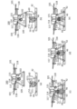
- FIG. 4A and 4B are diagrams showing how the drone 100 lands on the takeoff/landing section
- FIG. 4A is a diagram showing the drone 100 being obliquely above the table section 42, and FIG. is above the table portion 42
- FIG. 4(c) is a view showing a state where the tapered portion of the second engaging portion 111 is in contact with the packing 63
- FIG. 4E shows how the electrode 52 and the power receiving electrode 112 come into contact with each other
- FIG. 4E shows how the leg 109 of the drone 100 is held by the holding part 44.
- FIG. 5 is a flowchart executed by the control device 70, and the operation of the transport device 1 and the drone 100 of the first embodiment will be described below using FIGS. 4 and 5.
- FIG. 5 is a flowchart executed by the control device 70, and the operation of the transport device 1 and the drone 100 of the first embodiment will be described below using FIGS. 4 and 5.
- FIG. 5 is a flowchart executed by the control device 70, and the operation of the transport device 1 and the drone 100 of the first embodiment will be described below using FIGS. 4 and 5.
- FIG. 5 is a flowchart executed by the control device 70, and the operation of the transport device 1 and the drone 100 of the first embodiment will be described below using FIGS. 4 and 5.
- FIG. 5 is a flowchart executed by the control device 70, and the operation of the transport device 1 and the drone 100 of the first embodiment will be described below using FIGS. 4 and 5.
- FIG. 5 is a flowchart executed by the control device 70, and the operation of the transport device 1 and the drone 100 of
- the flowchart of FIG. 5 is executed, for example, when the conveying device 1 is positioned on a slope. It should be noted that driving the drive shaft 41 based on the output of the attitude detection section 43 in order to keep the table section 42 always horizontal is not preferable from the viewpoint of energy saving. For this reason, in the flowchart of FIG. 5 , the table portion 42 is kept horizontal when the drone 100 takes off and lands, and when the drone 100 does not take off even when the drone 100 lands on the table portion 42, the table portion by the drive shaft 41 42 is not driven.
- the control device 70 determines whether or not the drone 100 takes off from or lands on the table section 42 (step S1). Here, it is assumed that the control device 70 of the drone 100 proceeds to step S2 assuming that the drone 100 has landed on the table section 42 . Whether the drone 100 takes off or lands on the table unit 42 may be determined by communication between the carrier device 1 and the drone 100, or may be determined by an instruction from the control device 70 to the drone 100. . Further, when the drone 100 lands on the table section 42, the control device 70 preferably stops the movement of the carrier device 1 by the travel device 10 before issuing a landing instruction in step S4 described later. . On the other hand, when the drone 100 takes off from the table section 42 of the drone 100 , the control device 70 may move the carrier device 1 by the traveling device 10 .
- step S2 the control device 70 determines whether or not leveling drive is necessary to level the table section 42 (step S2).
- the control device 70 determines whether or not the leveling drive is necessary based on the output of the attitude detection section 43 .
- the control device 70 determines Yes in step S2 and proceeds to step S3.
- the control device 70 drives the three drive shafts 41 by the leveling motor 32 to level the table section 42 (step S3). Note that the control device 70 does not need to make the table section 42 completely horizontal, and may control the attitude of the table section 42 so that the drone 100 can safely land on the table section 42 .
- the rotating blades generate an air flow toward the downstream side, causing the main body to tilt at the time of landing.
- the control device drives the three drive shafts 41 so as to tilt the table section 42 by about 3° to 10° so that the drone 100 can easily land according to the landing characteristics of the drone 100. good.
- the drone 100 is flying toward the table section 42 as shown in FIG. 4(a). Specifically, the UAV control device 120 of the drone 100 flies toward the table section 42 based on the position information of the table section 42 and the position of the drone 100 measured by the second GNSS 108 . Note that the UAV control device 120 controls the position of the lens of the imaging device 102 to be directed downward in order to image the table section 42 using the imaging device 102 .
- the UAV control device 120 flies above the table section 42 so that the first engaging section 51 and the second engaging section 111 can be engaged, as shown in FIG. 4(b).
- the control device 70 issues a landing instruction to the UAV control device 120 (step S4).
- the UAV control device 120 moves downward, moving the tapered portion of the second engaging portion 111 to the tapered portion inside the first engaging portion 51 as shown in FIG.
- the tapered portion of the pipe portion 114 is engaged with the packing 63 .
- FIG. 4C the orientation of the lens of the imaging device 55 is shifted from the lower side to the horizontal direction. You may make it image the state of engagement with the joining part 111.
- FIG. 4C the orientation of the lens of the imaging device 55 is shifted from the lower side to the horizontal direction. You may make it image the state of engagement with the joining part 111.
- the packing 63 elastically deforms, and the power transmitting electrode 52 and the power receiving electrode 112 come into contact as shown in FIG. Further, since the weight of the drone 100 acts on the spring 45, the spring 45 is elastically deformed so as to be compressed.
- the weight of the drone 100 acts on the spring 45, and as shown in FIG. , the leg 109 engages the retainer 44 .
- a sensor for detecting contact with the power transmission device 50 is provided on the table portion 42, and the control device 70 terminates step S4 when the sensor detects that the table portion 42 has come into contact with the power transmission device 50. You may make it judge.
- the control device 70 communicates with the drone 100 and determines whether the UAV control device 120 requests power supply to the power receiving device 103 and fluid supply to the fluid device 113 (step S5).
- the UAV control device 120 requests power supply to the power receiving device 103 and fluid supply to the fluid device 113, and the process proceeds to step S6.
- the solenoid valve 116 is opened so that the fluid can be supplied from the fluid supply unit 60 .
- the control device 70 performs power transmission by the power transmission device 50 and fluid supply by the fluid supply unit 60 (step S6).
- the control device 70 turns on a switch (not shown) of the power transmission device 50 to start supplying power to the power receiving device 103, and drives the pump 34 to start supplying fluid to the fluid device 113 by the fluid supply unit 60. .
- the control device 70 determines whether power transmission by the power transmission device 50 and supply of fluid by the fluid supply unit 60 have ended (step S7).
- the UAV control device 120 transmits a signal indicating the end of charging to the control device 70 when the charge amount of the battery 105 reaches a predetermined charge amount.
- the UAV control device 120 closes the solenoid valve 116 and indicates the end of fluid supply to the control device 70 when the flow meter (not shown) provided in the tank 115 detects a predetermined flow rate. Send a signal.
- the control device 70 turns off a switch (not shown) of the power transmitting device 50 to end power supply to the power receiving device 103 . Further, the control device 70 stops driving the pump 34 when receiving a signal indicating the end of fluid supply.
- the control device 70 determines whether it is necessary to maintain the leveling of the table section 42 (step S8). When the take-off and landing of the drone 100 is expected, or when the movement route of the carrier device 1 is steeply inclined, the control device 70 determines Yes in step S8 and appropriately drives the drive shaft 41 to level the table portion 42. With the state properly maintained, go to step S10.
- the control device 70 determines No in step S8 and proceeds to step S9. Further, the control device 70 may determine No in step S8 when the imaging device 102 of the drone 100 performs imaging. This is because, when the drone 100 lands on the table section 42, the imaging by the imaging device 102 is taken from almost the same position as from the driver's seat of the conventional carrier device. ) is preferably taken into consideration.
- the control device 70 stops driving the drive shaft 41 by the leveling motor 32 (step S9), and proceeds to step S10.
- the control device 70 determines whether or not this flowchart can be ended (step S10).
- the control device 70 determines Yes in step S10 when the transporting of the transporting device 1 is completed or when the transporting device 1 is turned off, and terminates this flowchart.
- step S10 determines No in step S10 and proceeds to step S1.
- the control device 70 controls the attitude of the table section 42 based on the detection result of the attitude detection section 43, thereby realizing a takeoff and landing section where the drone 100 can easily take off. can do.
- the drone 100 of the first embodiment can be used for various purposes. For example, a spraying drone that sprays agricultural chemicals from the nozzle 118 onto the farmland, or a cleaning drone that sprays a cleaning solution for cleaning the solar panel from the nozzle 118 onto the solar panel.
- the control device 70 controls the attitude of the table section 42 based on the detection result of the attitude detection section 43.
- the device 1 can be implemented. Further, when the drone 100 lands on the table unit 42, the power receiving device 103 can be charged and the fluid can be supplied to the fluidic device 113 in a stable posture. It is possible to suppress the occurrence of troubles when supplying the fluid.
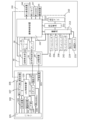
- FIG. 6 is a schematic diagram of a hydraulic excavator 200 representing the second embodiment
- FIG. 7 is a block diagram of main parts of the hydraulic excavator 200 and the drone 100 according to the second embodiment. 6 illustration of the holding portion 44 and the opening 46 of the leveling portion 40 is omitted, illustration of the power transmission electrode 52 of the power transmission device 50 is omitted, and illustration of each component of the fluid device 113 is omitted.
- FIG. 6 the hydraulic excavator 200 of the second embodiment is an automatic operation type or remote operation type construction machine without a driver's seat.
- the hydraulic excavator 200 may be automatically driven at a civil engineering site, and may be placed on a trailer and transported on a public road.
- a hydraulic excavator 200 of the second embodiment has a drive system 210 , a travel device 220 , a swing device 230 , a main device 240 and a working device 260 .
- the drive system 210 is a drive device that drives each element of the hydraulic excavator 200, and has a fuel cell 211, a fuel tank 212, and a storage battery 213 housed in the main device 240.
- the fuel cell 211 is a power generator that produces electricity by causing an electrochemical reaction between hydrogen and oxygen.
- the fuel tank 212 stores gaseous hydrogen in the second embodiment, and is provided with a remaining amount gauge (not shown) inside.
- the fuel tank 212 stores hydrogen compressed to several tens of MPa, and supplies the hydrogen to the fuel cell 211 via a hydrogen supply line (not shown).
- the storage battery 213 is a secondary battery that stores the electric power generated by the fuel cell 211 .
- the storage battery 213 can also be used as an auxiliary power source for driving the fuel cell 211 with the stored electric power, and various motors constituting the hydraulic excavator 200, the traveling device 220, the swing device 230, various cylinders, and the leveling motor 32 can be used. , the pump 34, the power transmission device 50, and the like.
- the battery 31 of the first embodiment can be omitted in the second embodiment.
- the traveling device 220 is of a crawler track type, and includes a pair of crawler belts 223 wound around an idler wheel 221 and a driving wheel 222.
- the driving wheels are driven by a traveling motor 124 to drive the pair of crawler belts.
- a hydraulic excavator 200 is running.
- the travel motor 124 is driven by electric power supplied from the storage battery 213, and an in-wheel motor is employed in the first embodiment.
- a hydraulic motor may be used as the travel motor 124 .
- the turning device 230 is arranged between the travel device 220 and the main device 240 .
- the turning device 230 includes a bearing (not shown) and a turning motor 231, and turns the main body device 240 and the working device 260 around the Z-axis.
- the main unit 240 of the first embodiment has a cylindrical shape with a flat upper surface, and the drone 100 can take off and land on this upper surface.
- the main unit 240 has a columnar shape in the first embodiment, it is not limited to this, and can have an arbitrary shape.
- the main unit 240 includes therein the fuel cell 211, the fuel tank 212, the storage battery 213, the fuel tank 212, the leveling motor 32 of the first embodiment, the container 33, and the pump 34. .
- the main unit 240 includes a third GNSS 247 that is a global positioning system, a third communication device 248, a third memory 249, and a heavy machine control unit that controls the hydraulic excavator 200 as a whole.
- a device 250 is provided.
- the swing portion 241 is pivotally supported such that a portion connected to one end of the main device 240 and a portion connected to the boom 253 are rotatable about the Z-axis indicating the vertical direction.
- the swing cylinder 242 is a cylinder whose one end is connected to the main unit 240 and whose other end is connected to the swing portion 241 .
- the expansion and contraction of the swing cylinder 242 rotates the working device 260 around the Z-axis in FIG.
- the third GNSS 247 measures the position of the hydraulic excavator 200 using artificial satellites.
- the third GNSS 247 may be provided on the top surface of the main unit 240 .
- the third communication device 248 is a wireless communication unit that has a transmitter, a receiver, various circuits, an antenna (not shown), and the like, and accesses the second communication device 106 and a wide area network such as the Internet.
- the third communication device 248 transmits the position of the table section 42 to the second communication device 106 based on the position of the excavator 200 detected by the third GNSS 247 .
- the third communication device 248 also receives image data captured by the imaging device 102 and detection results detected by the sensor group 104 from the second communication device 106 .
- the third memory 249 is a non-volatile memory (for example, flash memory), and stores various data and programs for driving the hydraulic excavator 200 and various data and programs for automatically operating the hydraulic excavator 200.
- non-volatile memory for example, flash memory
- the heavy equipment control device 250 has a CPU and is a control device that controls the hydraulic excavator 200 as a whole. In the second embodiment, the heavy equipment control device 250 cooperates with the UAV control device 120 to perform landing control of the drone 100, control of a series of operations for supplying electric power and fluid to the drone 100, and the like. there is The heavy equipment control device 250 also controls the attitude of the leveling section 40 based on the detection result of the attitude detection section 43 .
- the working device 260 has a boom 253 , a boom cylinder 254 , an arm 255 , an arm cylinder 256 , a bucket 257 and a bucket cylinder 258 .
- the boom 253 is a rotatable L-shaped component connected to the main unit 240 via the swing portion 241 and is rotated by the boom cylinder 254 .
- Arm 255 is connected to the tip of boom 253 and is rotated by arm cylinder 256 .
- a bucket 257 is connected to the tip of the arm 255 and rotated by a bucket cylinder 258 .
- a breaker or the like can be attached to the tip of the arm 255 instead of the bucket 257 .
- the boom cylinder 254 is a cylinder that is telescopically operated by electric power supplied from the storage battery 213 to drive the boom 253 .
- the arm cylinder 256 is a cylinder that is expanded and contracted by electric power supplied from the storage battery 213 to drive the arm 255 .
- the bucket cylinder 258 is a cylinder that is expanded and contracted by electric power supplied from the storage battery 213 to drive the bucket 257 .
- the swing cylinder 242, the boom cylinder 254, the arm cylinder 256, and the bucket cylinder 258 are driven by electric power from the storage battery 213, but hydraulic pressure is used to drive these cylinders. may
- the drone 100 of the second embodiment can be used for various purposes.
- a liquid such as water is supplied from the nozzle 118 to the excavated material excavated by the bucket 257 to adjust the water content ratio (water content) of the excavated material, or the water is supplied from the nozzle 118 to the civil engineering site.
- of liquid may be supplied to suppress the generation of dust at the civil engineering site.
- the heavy equipment control device 250 controls the attitude of the table section 42 based on the detection result of the attitude detection section 43, so that the drone 100 can take off and land.
- a hydraulic excavator 200 that is easy to operate can be realized. Further, when the drone 100 lands on the table unit 42, the power receiving device 103 can be charged and the fluid can be supplied to the fluidic device 113 in a stable posture. It is possible to suppress the occurrence of troubles when supplying the fluid.
- the heavy equipment control device 250 preferably stops movement of the hydraulic excavator 200 by the travel device 220 when the drone 100 lands on the table portion 42 .
- the heavy machinery control device 250 may move the carrier device 1 by the traveling device 220 when taking off from the table section 42 of the drone 100 .
- the heavy equipment control device 250 transmits movement information (for example, spatial coordinates of movement) of the work device 260 to the UAV control device 120.
- the UAV control device 120 may use the infrared sensors of the sensor group 104 to avoid collision with the work device 260, or may use LiDAR instead of the infrared sensors. It is desirable that the UAV control device 120 approaches the table section 42 from the other end side of the main device 240 where the work device 260 is not provided during landing.
- the UAV control device 120 preferably flies to the other end of the main unit 240 where the work device 260 is not provided, and then flies toward the destination.
- FIG. 8 is a schematic diagram of a hydraulic excavator 200 representing the third embodiment.
- the third embodiment differs in that a cleaning device 270 is provided instead of the bucket 257 of the hydraulic excavator 200 of the second embodiment.
- the cleaning device 270 cleans the solar panel 280 in cooperation with the drone 100.
- the cleaning device 270 has a rotating brush 271 and a blower (not shown).
- the control of the cleaning device 270 is performed by the heavy equipment control device 250 .
- the rotating brush 271 is a brush for wiping the surface of the solar panel 280 to clean the solar panel 280 .
- the rotating brush 271 has a structure that can be rotated forward and backward by a motor (not shown). Note that cleaning liquid or water (pure water) may be discharged from the rotating brush 271 toward the surface of the solar panel 280 .
- the cleaning liquid and water (pure water) may be supplied using the container 33 and the pump 34 .
- a blower (not shown) blows compressed gas (e.g., air) onto the surface of the solar panel 280, cleaning liquid and water (pure water) discharged from the nozzle 118 of the drone 100 onto the surface of the solar panel 280, and a rotating brush.
- compressed gas e.g., air
- cleaning liquid and water (pure water) discharged from the nozzle 118 of the drone 100 onto the surface of the solar panel 280 and a rotating brush.
- the cleaning liquid and water (pure water) discharged from 271 onto the surface of the solar panel 280 are blown off.
- Compressed gas may be supplied using the container 33 and the pump 34 . Note that the container 33 and the pump 34 may be provided separately for liquid and gas.
- the rotating brush 271 wipes the surface of the solar panel 280 in response to the discharge of cleaning liquid or water (pure water) from the nozzle 118 of the drone 100 onto the surface of the solar panel 280 (not shown). blows off the cleaning liquid and water (pure water), the solar panel 280 can be cleaned efficiently.
- One of the supply of the cleaning liquid or water (pure water) by the drone 100 and the wiping by the rotating brush 271 may be omitted.
- an elevating mechanism is provided in the second engaging portion 111 , and after the leg portion 109 is held by the holding portion 44 , the second engaging portion 111 is lowered by the elevating mechanism so that the first engaging portion 51 and the first engaging portion 51 are separated from each other. You may make it engage with the 2 engagement part 111.
- the carrier device 1 and the hydraulic excavator 200 may be of a type with a driver's seat.
- the carrier device 1 and the hydraulic excavator 200 may be internal combustion engines driven by light oil, ammonia, or hydrogen.
- the working device 260 of the hydraulic excavator 200 is not limited to one, and a plurality of working devices 260 may be provided in the main body device 240. Moreover, each configuration of the first embodiment to the third embodiment may be combined as appropriate.
- Reference Signs List 1 conveying device 30 body portion 32 leveling motor 40 leveling portion 41 drive shaft 42 table portion 43 attitude detection portion 44 holding portion 45 spring 46 opening portion 50 power transmission device 51 first engagement portion 52 power transmission electrode 60 fluid supply portion 70 control device 100 Drone 111 Second engagement portion 112 Power receiving electrode 113 Fluid device 120 UAV control device 200 Hydraulic excavator 270 Cleaning device
Landscapes
- Engineering & Computer Science (AREA)
- Aviation & Aerospace Engineering (AREA)
- Remote Sensing (AREA)
- Transportation (AREA)
- Control Of Position, Course, Altitude, Or Attitude Of Moving Bodies (AREA)
Abstract
In order to provide a moving device which facilitates taking off and landing of an unmanned flying body, the moving device comprises: a body device which travels by a travel device; a taking-off/landing unit which is provided to the body device and on which the unmanned flying body takes off and lands; and a leveling table which is provided to the taking-off/landing unit and which allows adjustment of an inclination amount with respect to the vertical axis.
Description
本発明は、移動装置および無人飛行装置に関し、無人飛行体の離着陸が容易な移動装置およびスペース効率の良い無人飛行装置に関する。
The present invention relates to a mobile device and an unmanned flying device, and more particularly to a mobile device that facilitates takeoff and landing of an unmanned flying device and an unmanned flying device that is space efficient.
従来より、油圧ショベルやブルドーザなどの作業機械に無人航空体を離着陸させるための離着陸ポートを設けることが提案されている。また、この離着陸ポートにて無人飛行体に充電を行うことが特許文献1に開示されている。
Conventionally, it has been proposed to equip work machines such as hydraulic excavators and bulldozers with takeoff and landing ports for taking off and landing unmanned aerial vehicles. Further, Patent Document 1 discloses that an unmanned flying object is charged at the take-off/landing port.
しかしながら、特許文献1は、作業機械が傾斜地で使用されることが考慮されておらず、離着陸ポートが傾斜している場合には、無人飛行体が離着陸できない虞があった。また、特許文献1は、無人航空体に流体を供給することについての開示はなかった。
However, Patent Document 1 does not take into consideration that the work machine is used on a slope, and if the takeoff/landing port is sloped, there is a risk that the unmanned air vehicle will not be able to take off and land. Also, Patent Literature 1 does not disclose supplying fluid to an unmanned aerial vehicle.
そこで、本第1発明は、無人飛行体の離着陸が容易な移動装置を提供することを目的とする。
また、本第2発明は、受電装置と流体装置とを設けた場合でも、スペース効率の良い無人飛行装置を提供することを目的とする。 SUMMARY OF THE INVENTION Accordingly, it is an object of the first invention to provide a mobile device that facilitates takeoff and landing of an unmanned air vehicle.
A second object of the present invention is to provide an unmanned flying device with good space efficiency even when a power receiving device and a fluidic device are provided.
本第1発明に係る移動装置は、走行装置により走行する本体装置と、前記本体装置に設けられ、無人飛行体が離着陸する離着陸部と、前記離着陸部に設けられ、鉛直軸に対する傾斜量が調整可能なレベリングテーブルと、を備えている。
本第2発明に係る無人飛行装置は、プロペラを有した飛行装置と、着陸部に着陸する際に、前記着陸部に設けられた第1係合部と係合する第2係合部と、前記第2係合部の外側に設けられた受電装置と、前記第2係合部の内側に設けられた流体装置と、を備えている。 A mobile device according to a first aspect of the present invention comprises a main unit that travels by a traveling device, a takeoff and landing unit provided in the main unit for taking off and landing of an unmanned flying object, and a takeoff and landing unit provided in the takeoff and landing unit for adjusting an amount of inclination with respect to a vertical axis. With a possible leveling table.
An unmanned flying device according to a second aspect of the present invention comprises a flight device having a propeller; a second engaging portion that engages with a first engaging portion provided on the landing portion when landing on the landing portion; A power receiving device provided outside the second engaging portion, and a fluid device provided inside the second engaging portion.
本第1発明によれば、離着陸部に鉛直軸に対する傾斜量が調整可能なレベリングテーブルが設けられているので、無人飛行体の離着陸が容易な移動装置を実現することができる。
本第2発明によれば、第2係合部の外側に受電装置が設けられており、第2係合部の内側に流体装置が設けられているので、スペース効率の良い無人飛行装置を実現することができる。 According to the first aspect of the present invention, since the take-off/landing section is provided with a leveling table capable of adjusting the amount of inclination with respect to the vertical axis, it is possible to realize a mobile device that facilitates take-off and landing of the unmanned air vehicle.
According to the second aspect of the invention, the power receiving device is provided outside the second engaging portion, and the fluidic device is provided inside the second engaging portion, thereby realizing an unmanned flying device with good space efficiency. can do.
以下に、本発明の実施形態の建設機械を添付の図面に基づいて詳細に説明する。なお、以下で説明する実施形態により、本発明が限定されるものではない。本第1実施形態では、傾斜地の上空を飛行する無人航空機であるUAV(Unmanned Aerial Vehicle、以下ドローン100という)をサポートする搬送装置1を例に説明を続ける。なお、以下の説明では、便宜上、鉛直方向をZ方向、水平面内において直交する二軸方向をX方向及びY方向とする。
A construction machine according to an embodiment of the present invention will be described in detail below based on the attached drawings. In addition, the present invention is not limited by the embodiments described below. In the first embodiment, the description will be continued with an example of the transport device 1 that supports a UAV (Unmanned Aerial Vehicle, hereinafter referred to as a drone 100), which is an unmanned aerial vehicle that flies over a slope. In the following description, for the sake of convenience, the vertical direction is defined as the Z direction, and the biaxial directions orthogonal to each other in the horizontal plane are defined as the X direction and the Y direction.
(第1実施形態)
図1は本第1実施形態を表す搬送装置1の概要図であり、図1(a)は上面図であり、図1(b)は正面図であり、図1(c)は側面図であり、図2は本第1実施形態の搬送装置1とドローン100との主要部のブロック図である。先ずは図1および図2を用いて搬送装置1の構成につき説明を行う。なお、図1(b)は図1(a)のA-A断面として図示している。
なお、本第1実施形態の搬送装置1は、運転席が無い自動運転タイプもしくは遠隔運転タイプである。搬送装置1は、走行装置10と、ベース部20と、本体部30と、レベリング部40と、送電装置50と、流体供給部60と、撮像装置55と、第1GNSS65(Global Navigation Satellite System)と、第1通信装置66と、第1メモリ67と、制御装置70と、を有している。 (First embodiment)
1A and 1B are schematic diagrams of aconveying apparatus 1 representing the first embodiment, FIG. 1A is a top view, FIG. 1B is a front view, and FIG. 1C is a side view. FIG. 2 is a block diagram of main parts of the transport device 1 and the drone 100 of the first embodiment. First, the configuration of the conveying device 1 will be described with reference to FIGS. 1 and 2. FIG. Note that FIG. 1(b) is shown as a cross section taken along the line AA of FIG. 1(a).
In addition, theconveying apparatus 1 of the first embodiment is of an automatic operation type or a remote operation type without a driver's seat. The transport device 1 includes a traveling device 10, a base portion 20, a main body portion 30, a leveling portion 40, a power transmission device 50, a fluid supply portion 60, an imaging device 55, and a first GNSS 65 (Global Navigation Satellite System). , a first communication device 66 , a first memory 67 and a control device 70 .
図1は本第1実施形態を表す搬送装置1の概要図であり、図1(a)は上面図であり、図1(b)は正面図であり、図1(c)は側面図であり、図2は本第1実施形態の搬送装置1とドローン100との主要部のブロック図である。先ずは図1および図2を用いて搬送装置1の構成につき説明を行う。なお、図1(b)は図1(a)のA-A断面として図示している。
なお、本第1実施形態の搬送装置1は、運転席が無い自動運転タイプもしくは遠隔運転タイプである。搬送装置1は、走行装置10と、ベース部20と、本体部30と、レベリング部40と、送電装置50と、流体供給部60と、撮像装置55と、第1GNSS65(Global Navigation Satellite System)と、第1通信装置66と、第1メモリ67と、制御装置70と、を有している。 (First embodiment)
1A and 1B are schematic diagrams of a
In addition, the
走行装置10は、搬送装置1を移動させるものであり、駆動輪11と、従動輪12と、履帯13と、支持体14とを有している。また、走行装置10は、走行モータ15と、中央フレーム16と、一対のサイドフレーム17と、一対のリンク機構18と、カプラ19と、を有している。本第1実施形態において、走行装置10は、カプラ19(詳細後述)によりベース部20から着脱可能となっている。
The traveling device 10 moves the conveying device 1, and has driving wheels 11, driven wheels 12, crawler belts 13, and supports . The travel device 10 also includes a travel motor 15 , a central frame 16 , a pair of side frames 17 , a pair of link mechanisms 18 , and a coupler 19 . In the first embodiment, the travel device 10 is detachable from the base portion 20 by a coupler 19 (details will be described later).
本第1実施形態では、1つの駆動輪11と2つの従動輪12とにより、三角形状が形成されている。なお、2つの従動輪12の間には、2つの従動輪12よりも小さな従動輪が複数設けられている。
履帯13は、1つの駆動輪11と2つの従動輪12とに掛け回されている。支持体14は、駆動輪11と従動輪12とを回転可能に支持している。本第1実施形態の三角形状の履帯式走行体は4つであるので、不整地においても搬送装置1を安定して走行することができる。なお、走行装置10として、前輪と後輪とに履帯を巻いた無限軌道を用いてもよい。 In the first embodiment, onedriving wheel 11 and two driven wheels 12 form a triangular shape. A plurality of driven wheels smaller than the two driven wheels 12 are provided between the two driven wheels 12 .
Thecrawler belt 13 is wound around one drive wheel 11 and two driven wheels 12 . The support 14 rotatably supports the drive wheel 11 and the driven wheel 12 . Since there are four triangular crawler belt-type traveling bodies in the first embodiment, the conveying apparatus 1 can travel stably even on rough terrain. As the traveling device 10, an endless track in which crawler belts are wound around the front wheels and the rear wheels may be used.
履帯13は、1つの駆動輪11と2つの従動輪12とに掛け回されている。支持体14は、駆動輪11と従動輪12とを回転可能に支持している。本第1実施形態の三角形状の履帯式走行体は4つであるので、不整地においても搬送装置1を安定して走行することができる。なお、走行装置10として、前輪と後輪とに履帯を巻いた無限軌道を用いてもよい。 In the first embodiment, one
The
本第1実施形態において、走行モータ15(図2参照)は、駆動輪11の裏面側に駆動輪11に駆動力を伝達するインホィールモータを採用している。インホィールモータの回転軸は駆動輪11の回転軸と接続されており、インホィールモータの回転駆動力により駆動輪11が回転し、ひいては履帯13に駆動力が伝達される。なお、走行モータ15としてはインホィールモータとは異なるモータを採用しても構わない。
In the first embodiment, the traveling motor 15 (see FIG. 2) employs an in-wheel motor that transmits the driving force to the driving wheels 11 on the rear side of the driving wheels 11 . The rotating shaft of the in-wheel motor is connected to the rotating shaft of the driving wheel 11 , and the rotating driving force of the in-wheel motor rotates the driving wheel 11 , thereby transmitting the driving force to the crawler belt 13 . A motor different from the in-wheel motor may be employed as the traveling motor 15 .
中央フレーム16は、Y方向に離間した2つの駆動輪11の間に位置したフレームであり、一対のリンク機構18を介して一対のサイドフレーム17と接続されている。中央フレーム16は、その上面にベース部20と連結するためのカプラ19が設けられている。
The center frame 16 is a frame positioned between two drive wheels 11 spaced apart in the Y direction, and is connected to a pair of side frames 17 via a pair of link mechanisms 18 . The central frame 16 is provided with a coupler 19 for connecting with the base portion 20 on its upper surface.
一対のサイドフレーム17は、不図示の軸受けを介してそれぞれの駆動輪11に接続されたフレームである。
A pair of side frames 17 are frames connected to the respective drive wheels 11 via bearings (not shown).
一対のリンク機構18は、Z字状または逆Z字状をしており、一端が一対のサイドフレーム17に接続され、他端が中央フレーム16に接続された一対の接続部材18aと、一端が中央フレーム16側の接続部材18aに接続され、他端がサイドフレーム17側の接続部材18aに接続されたアクチュエータ18bを有している。なお、一対の接続部材18aは、Z方向に離間して2つ設けられている。
The pair of link mechanisms 18 has a Z-shape or an inverted Z-shape, and includes a pair of connection members 18a connected at one end to the pair of side frames 17 and at the other end to the central frame 16, and at one end to the center frame 16. It has an actuator 18b connected to the connection member 18a on the side of the central frame 16 and having the other end connected to the connection member 18a on the side frame 17 side. It should be noted that two pairs of connection members 18a are provided spaced apart in the Z direction.
アクチュエータ18bは、傾斜して設けられており、伸縮により一対のサイドフレーム17をZ方向およびY方向に駆動するものである。アクチュエータ18bは、一対のサイドフレーム17を介して、駆動輪11と従動輪12と履帯13とをZ方向およびY方向に移動する。これにより、走行装置10は、Z方向およびY方向の大きさ(サイズ)を変更することができる。なお、アクチュエータ18bとしては、油圧ジャッキや電動ジャッキを用いることができるが、これに限定されるものではない。
The actuator 18b is provided at an angle, and expands and contracts to drive the pair of side frames 17 in the Z direction and the Y direction. Actuator 18b moves drive wheel 11, driven wheel 12, and crawler belt 13 in the Z and Y directions via a pair of side frames 17. As shown in FIG. Thereby, the travel device 10 can change the size in the Z direction and the Y direction. A hydraulic jack or an electric jack can be used as the actuator 18b, but the actuator 18b is not limited to this.
本第1実施形態において、カプラ19は、V字状の切り欠きを有し、ベース部20の上面に4つ設けられているが、1つでもよく、その数は任意に設定することができる。カプラ19は、ベース部20の下面に設けられた-Z方向に伸びた不図示のピンと、V字状の切り欠きと、を係合することにより、走行装置10とベース部20とを連結させている。また、カプラ19は、ピンとの係合を解除することにより、走行装置10とベース部20とを連結を解除している。なお、カプラ19とピンとの連結構造は、例えば特開2000―6856号に開示されている。また、カプラ19とピンとの着脱は、電磁石により行うようにしてもよい。
In the first embodiment, the coupler 19 has a V-shaped notch, and four of them are provided on the upper surface of the base portion 20. However, the coupler 19 may be one, and the number thereof can be set arbitrarily. . The coupler 19 connects the travel device 10 and the base portion 20 by engaging a pin (not shown) extending in the -Z direction provided on the lower surface of the base portion 20 and a V-shaped notch. ing. Further, the coupler 19 releases the connection between the travel device 10 and the base portion 20 by releasing the engagement with the pin. Incidentally, the connection structure between the coupler 19 and the pin is disclosed, for example, in Japanese Patent Application Laid-Open No. 2000-6856. Also, the attachment and detachment of the coupler 19 and the pin may be performed by an electromagnet.
ベース部20は、本第1実施形態において、矩形状の部材であり、上面に本体部30が載置されており、下面に折りたたみ可能な脚部21が設けられている。脚部21は、ベース部20を走行装置10との着脱前後で自立させる部材である。本第1実施形態において、脚部21は、ベース部20に2つ設けられているがその数は任意に設定することができる。また、ベース部20の形状も矩形状に限定されず、楕円形状など任意の形状とすることができる。また、ベース部20は、アクチュエータ18bの駆動によりZ方向の位置を変更することができる。
In the first embodiment, the base part 20 is a rectangular member, the main body part 30 is placed on the upper surface, and the foldable legs 21 are provided on the lower surface. The leg portion 21 is a member that allows the base portion 20 to stand on its own before and after attachment/detachment to/from the travel device 10 . In the first embodiment, two leg portions 21 are provided on the base portion 20, but the number can be set arbitrarily. Also, the shape of the base portion 20 is not limited to a rectangular shape, and may be an arbitrary shape such as an elliptical shape. Also, the base portion 20 can change its position in the Z direction by driving the actuator 18b.
本体部30は、ベース部20の上面に固設されており、走行モータ15やアクチュエータ18bなどの電気的な構成要素に電力を供給するバッテリ31と、レベリング部40を駆動するレベリングモータ32と、流体を貯蔵する容器33と、この流体をドローン100に吐出可能なポンプ34と、を内部に収容している。
The body portion 30 is fixed on the upper surface of the base portion 20, and includes a battery 31 that supplies electric power to electrical components such as the travel motor 15 and the actuator 18b, a leveling motor 32 that drives the leveling portion 40, A container 33 for storing fluid and a pump 34 capable of discharging this fluid to the drone 100 are housed inside.
バッテリ31は、充放電が繰り返しできる二次電池であり、リチウムイオン二次電池やリチウムポリマー二次電池などを用いることができる。バッテリ31は、リチウムイオン二次電池の場合は定電流定電圧受電方式により充電することができ、ニッケル水素二次電池やニッカド二次電池の場合は定電流充電により充電することができる。なお、図2のブロック図では一部の図示を省略しているが、バッテリ31は、搬送装置1の電気的な構成要素のすべてに電力を供給している。
The battery 31 is a secondary battery that can be repeatedly charged and discharged, and a lithium ion secondary battery, a lithium polymer secondary battery, or the like can be used. The battery 31 can be charged by a constant-current and constant-voltage receiving method in the case of a lithium-ion secondary battery, and can be charged by constant-current charging in the case of a nickel-hydrogen secondary battery or a nickel-cadmium secondary battery. Although part of the illustration is omitted in the block diagram of FIG.
レベリングモータ32は、レベリング部40を構成する後述の3つの駆動軸41をそれぞれ独立してZ方向に沿って駆動するためのモータである。本第1実施形態において、レベリングモータ32は、3つのDCモータを用いているがこれに限定されるものではない。なお、レベリングモータ32は、バッテリ31より供給された電力により駆動している。
The leveling motor 32 is a motor for independently driving three drive shafts 41, which constitute the leveling section 40, along the Z direction. In the first embodiment, three DC motors are used as the leveling motors 32, but the number of DC motors is not limited to this. The leveling motor 32 is driven by electric power supplied from the battery 31 .
容器33は、液体や気体といった流体を貯蔵する容器であり、本第1実施形態において農薬や、洗浄液や、薬液や、純水、飲料水といった液体を供給するものである。なお、ドローンが気体燃料により飛行する場合には、気体燃料(水素や酸素など)を容器33に貯蔵してもよい。
The container 33 is a container for storing fluids such as liquids and gases, and supplies liquids such as agricultural chemicals, cleaning liquids, chemical solutions, pure water, and drinking water in the first embodiment. Note that when the drone flies with gaseous fuel, the gaseous fuel (hydrogen, oxygen, etc.) may be stored in the container 33 .
ポンプ34は、容器33に貯蔵された流体を後述の流体供給部60を介して、ドローン100に供給するポンプである。ポンプ34は、本第1実施形態において、直流ポンプや、モータの代わりに電磁石を用いた直流電磁モータなどを用いることができる。なお、ポンプ34は、バッテリ31より供給された電力により駆動している。
The pump 34 is a pump that supplies the fluid stored in the container 33 to the drone 100 via the fluid supply unit 60 described later. In the first embodiment, the pump 34 may be a direct current pump or a direct current electromagnetic motor using an electromagnet instead of a motor. It should be noted that the pump 34 is driven by power supplied from the battery 31 .
レベリング部40は、3つの駆動軸41と、テーブル部42と、姿勢検出部43と、保持部44と、ばね45と、開口部46と、を備え、本第1実施形態ではドローン100が離着陸する離着陸部として機能している。
The leveling section 40 includes three drive shafts 41, a table section 42, an attitude detection section 43, a holding section 44, a spring 45, and an opening section 46. In the first embodiment, the drone 100 takes off and lands. It functions as a take-off and landing part.
3つの駆動軸41は、駆動軸41どうしの間隔が均等になるように配置されており、一端が本体部30側に接続され、他端がテーブル部42に接続されている。3つの駆動軸41は、レベリングモータ32によりZ方向に沿って駆動する。すなわち、テーブル部42は鉛直軸に対する傾斜量が調整可能となっている。
The three drive shafts 41 are arranged so that the intervals between the drive shafts 41 are equal, one end is connected to the main body portion 30 side, and the other end is connected to the table portion 42 . The three drive shafts 41 are driven along the Z direction by the leveling motor 32 . That is, the table portion 42 can adjust the amount of inclination with respect to the vertical axis.
図3は、搬送装置1が傾斜地にあり、駆動軸41を駆動させた状態を示す概要図である。レベリングモータ32により駆動軸41を駆動させることにより、テーブル部42を水平にすることが可能となる。このため、ドローン100がテーブル部42に容易に離着陸することが可能となる。
FIG. 3 is a schematic diagram showing a state in which the transport device 1 is on a slope and the drive shaft 41 is driven. By driving the drive shaft 41 with the leveling motor 32, the table section 42 can be leveled. Therefore, the drone 100 can easily take off and land on the table section 42 .
テーブル部42は、本体部30の上面側(+Z側)に設けられており、ドローン100が離着陸可能な大きさとなっている。図1において、テーブル部42は1つのドローン100が着陸しているが、2つ以上のドローン100が離着陸するような大きさとしてもよい。この場合、レベリング部40は1つとしてもよく、ドローン100の数に応じて複数としてもよい。なお、テーブル部42の形状は、本第1実施形態では円形としているが矩形状でも構わない。
The table section 42 is provided on the upper surface side (+Z side) of the main body section 30 and has a size that allows the drone 100 to take off and land. In FIG. 1, one drone 100 lands on the table section 42, but it may be sized so that two or more drones 100 can take off and land. In this case, one leveling unit 40 may be provided, or a plurality of leveling units may be provided according to the number of drones 100 . Although the shape of the table portion 42 is circular in the first embodiment, it may be rectangular.
姿勢検出部43は、図1では不図示ながらテーブル部42の上面もしくは下面に設けられ、テーブル部42の姿勢を検出している。姿勢検出部43としては、傾斜計や水準器などを用いることができる。前述の駆動軸41は、姿勢検出部43の検出結果に基づいて駆動される。
Although not shown in FIG. 1, the posture detection unit 43 is provided on the top surface or the bottom surface of the table unit 42 and detects the posture of the table unit 42 . As the posture detection unit 43, an inclinometer, a spirit level, or the like can be used. The aforementioned drive shaft 41 is driven based on the detection result of the attitude detection section 43 .
保持部44は、ドローン100に設けられている後述の脚部109と係合してドローン100をテーブル部42上に保持するものである。本第1実施形態において、保持部44は、テーブル部42に設けられ、脚部109と係合可能な矩形状の溝となっている。なお、溝の形状は、脚部109の形状に応じて任意の形状とすることができる。また、保持部44は、溝ではなく、脚部109を機械的または電磁的にロックするロック機構としてもよい。
The holding section 44 engages with a leg section 109 provided on the drone 100 to hold the drone 100 on the table section 42 . In the first embodiment, the holding portion 44 is provided in the table portion 42 and is a rectangular groove that can be engaged with the leg portion 109 . It should be noted that the shape of the groove can be any shape according to the shape of the leg portion 109 . Further, the holding portion 44 may be a lock mechanism that mechanically or electromagnetically locks the leg portion 109 instead of the groove.
ばね45は、弾性部材であり、一端がテーブル部42に接続され、他端が送電装置50(後述の第1係合部51)に接続されている。ばね45は、ドローン100がテーブル部42に着陸しているときにはドローン100の自重により縮むように弾性変形する。このときに、送電装置50は、テーブル部42により保持される。
The spring 45 is an elastic member, one end of which is connected to the table portion 42 and the other end of which is connected to the power transmission device 50 (first engaging portion 51 described later). The spring 45 is elastically deformed so as to contract under the weight of the drone 100 when the drone 100 lands on the table section 42 . At this time, the power transmission device 50 is held by the table portion 42 .
開口部46は、テーブル部42に設けられた貫通孔である。本第1実施形態では、開口部46は、テーブル部42の中央に設けられ、送電装置50の配線をレベリング部40と送電装置50との間で引き回すための経路となっている。
また、開口部46は、後述の供給管61をレベリング部40と流体供給部60との間で引き回すための経路となっている。 Theopening 46 is a through hole provided in the table portion 42 . In the first embodiment, the opening 46 is provided in the center of the table portion 42 and serves as a route for routing the wiring of the power transmission device 50 between the leveling portion 40 and the power transmission device 50 .
Further, theopening 46 serves as a path for routing a supply pipe 61 (to be described later) between the leveling section 40 and the fluid supply section 60 .
また、開口部46は、後述の供給管61をレベリング部40と流体供給部60との間で引き回すための経路となっている。 The
Further, the
送電装置50(図4参照)は、ばね45を介してテーブル部42の上面側(+Z側)に設けられている。送電装置50は、ドローン100に設けられている後述の受電装置103に電力を供給するものである。送電装置50は、第1係合部51と、送電電極52と、不図示のスイッチとを有している。
The power transmission device 50 (see FIG. 4) is provided on the upper surface side (+Z side) of the table portion 42 via the spring 45 . The power transmission device 50 supplies power to a power reception device 103 provided in the drone 100 , which will be described later. The power transmission device 50 has a first engaging portion 51, a power transmission electrode 52, and a switch (not shown).
第1係合部51は、ドローン100の後述する第2係合部111と係合可能であり、内側にテーブル部42側(-Z側)に向けて縮径するテーパ形状の開口部を有している。
送電電極52は、このテーパ部に設けられており、受電装置103のテーパ部に設けられた受電電極112に接触することにより給電が行われている。なお、送電電極52とバッテリ31とは、開口部46を経由する配線により接続されている。 The first engagingportion 51 is capable of engaging with a second engaging portion 111 of the drone 100, which will be described later, and has a tapered opening that decreases in diameter toward the table portion 42 side (−Z side). are doing.
Thepower transmission electrode 52 is provided on this tapered portion, and power is supplied by contacting the power receiving electrode 112 provided on the tapered portion of the power receiving device 103 . In addition, the power transmission electrode 52 and the battery 31 are connected by wiring passing through the opening 46 .
送電電極52は、このテーパ部に設けられており、受電装置103のテーパ部に設けられた受電電極112に接触することにより給電が行われている。なお、送電電極52とバッテリ31とは、開口部46を経由する配線により接続されている。 The first engaging
The
なお、送電装置50と受電装置103とによる給電は、ワイヤレス給電を採用してもよい。ワイヤレス給電は、非接触で電力を供給するものであり、磁界共鳴方式や電磁誘導方式などが知られている。不図示のスイッチは、送電装置50による受電装置103への給電を行うかどうかのオン・オフスイッチである。
Wireless power feeding may be employed for power feeding by the power transmitting device 50 and the power receiving device 103 . Wireless power supply supplies electric power in a non-contact manner, and magnetic resonance methods, electromagnetic induction methods, and the like are known. A switch (not shown) is an on/off switch for determining whether power is supplied to the power receiving apparatus 103 by the power transmitting apparatus 50 .
流体供給部60(図4参照)は、ポンプ34からの流体をドローン100に供給するものである。本第1実施形態において、流体供給部60は、供給管61と、ジョイント62と、パッキン63とを有している。
The fluid supply unit 60 (see FIG. 4) supplies the fluid from the pump 34 to the drone 100. In the first embodiment, the fluid supply section 60 has a supply pipe 61 , a joint 62 and a packing 63 .
供給管61は、一端がポンプ34に接続され、開口部46を経由して他端が第1係合部51の内部に位置するように設けられている。ジョイント62は、後述の配管部114と係合するテーパ形状であり、供給管61の他端側に設けられている。
パッキン63は、ジョイント62に設けられており、本第1実施形態では弾性変形可能なゴムパッキンとなっている。なお、供給管61や電線は、開口部46に代えて、駆動軸41を中空形状として、この中空部分を利用して引き回すようにしてもよい。この場合、供給管61と電線とは異なる駆動軸41の中空部分を引き回すことが望ましい。 Thesupply pipe 61 is provided so that one end is connected to the pump 34 and the other end is positioned inside the first engaging portion 51 via the opening 46 . The joint 62 has a tapered shape that engages with a pipe portion 114 described later, and is provided on the other end side of the supply pipe 61 .
The packing 63 is provided on the joint 62 and is an elastically deformable rubber packing in the first embodiment. Instead of theopening 46, the drive shaft 41 may have a hollow shape, and the hollow portion may be used to route the supply pipe 61 and the electric wire. In this case, it is desirable to route the hollow portion of the drive shaft 41 that is different from the supply pipe 61 and the electric wire.
パッキン63は、ジョイント62に設けられており、本第1実施形態では弾性変形可能なゴムパッキンとなっている。なお、供給管61や電線は、開口部46に代えて、駆動軸41を中空形状として、この中空部分を利用して引き回すようにしてもよい。この場合、供給管61と電線とは異なる駆動軸41の中空部分を引き回すことが望ましい。 The
The packing 63 is provided on the joint 62 and is an elastically deformable rubber packing in the first embodiment. Instead of the
本第1実施形態では、第1係合部51内にドローン100に電力を供給する送電装置50の一部と、ドローン100に流体を供給する流体供給部60の一部とを設けているので、第1係合部51に後述の第2係合部111を係合させることにより、電力および流体の供給が可能となり、ドローン100の大型化を抑制することができる。
In the first embodiment, part of the power transmission device 50 that supplies electric power to the drone 100 and part of the fluid supply unit 60 that supplies fluid to the drone 100 are provided in the first engaging portion 51. By engaging a second engaging portion 111 (to be described later) with the first engaging portion 51, electric power and fluid can be supplied, and an increase in the size of the drone 100 can be suppressed.
撮像装置55は、レンズや撮像素子や画像処理エンジンなどを有し、動画や静止画を撮像するデジタルカメラである。本第1実施形態において、撮像装置55は、本体部30の側面であって、搬送装置1の進行方向側(-X側)に設けられている。撮像装置55で撮像された画像および第1GNSS65が測位した位置情報に基づいて、搬送装置1の自動運転もしくは遠隔操作による運転が行われる。搬送装置1を遠隔運転する場合には、撮像装置55で撮像された画像および第1GNSS65が測位した位置情報は、搬送装置1とは遠隔に設けられた中央制御装置に送信される。なお、本体部30に設けられる撮像装置55の数は複数でもよく、本体部30の左右前後方向のそれぞれに撮像装置55を設けてもよい。
The imaging device 55 is a digital camera that has a lens, an imaging device, an image processing engine, etc., and captures moving images and still images. In the first embodiment, the imaging device 55 is provided on the side surface of the main body 30 and on the traveling direction side (−X side) of the conveying device 1 . Based on the image captured by the imaging device 55 and the position information determined by the first GNSS 65, the transportation device 1 is automatically operated or remotely operated. When the transportation device 1 is operated remotely, the image captured by the imaging device 55 and the position information obtained by positioning by the first GNSS 65 are transmitted to a central control device provided remotely from the transportation device 1 . Note that the number of imaging devices 55 provided in the main body 30 may be plural, and the imaging devices 55 may be provided in each of the left, right, front, and rear directions of the main body 30 .
また、撮像装置55に代えて、もしくは、撮像装置55と併用して電磁波を照射するLiDAR(Light Detection and Ranging)により搬送装置1の周囲の障害物や路面形状を検出したり、道幅を検出したり、目的地までの距離を検出するようにしてもよい。
LiDAR (Light Detection and Ranging), which emits electromagnetic waves instead of the imaging device 55 or in combination with the imaging device 55, detects obstacles and road surface shapes around the transport device 1, and detects road width. Alternatively, the distance to the destination may be detected.
第1GNSS65は、人工衛星を利用して搬送装置1の位置を測位するものである。第1通信装置66は、送信機と、受信機と、各種回路と、不図示のアンテナなどを有し、ドローン100に設けられた後述の第2通信装置106やインターネット等の広域ネットワークにアクセスする無線通信ユニットである。本第1実施形態において、第1通信装置66は、第1GNSS65が検出した搬送装置1の位置に基づいて、テーブル部42の位置を第2通信装置106に送信する。
The first GNSS 65 measures the position of the transport device 1 using artificial satellites. The first communication device 66 has a transmitter, a receiver, various circuits, an antenna (not shown), and the like, and accesses a second communication device 106 provided in the drone 100 and a wide area network such as the Internet. A wireless communication unit. In the 1st Embodiment of this invention, the 1st communication apparatus 66 transmits the position of the table part 42 to the 2nd communication apparatus 106 based on the position of the conveying apparatus 1 which 1st GNSS65 detected.
第1メモリ67は、不揮発性のメモリ(例えばフラッシュメモリ)であり、搬送装置1の各要素を駆動するための各種データやプログラム、搬送装置1を自動運転するための各種データやプログラムを記憶している。
The first memory 67 is a non-volatile memory (for example, flash memory), and stores various data and programs for driving each element of the transport device 1 and various data and programs for automatically operating the transport device 1 . ing.
制御装置70は、CPUを備えており、搬送装置1全体を制御するとともに、ドローン100と協働するものである。本第1実施形態において、制御装置70は、ドローン100のUAV制御装置120と協働して、ドローン100の着地制御や、ドローン100に電力や流体を供給するための一連の動作の制御などを行っている。また、制御装置70は、姿勢検出部43の検出結果に基づいて、レベリング部40の姿勢の制御を行っている。また、制御装置70は、搬送装置1が狭い場所を移動する際には、アクチュエータ18bを駆動してY方向に離間する一対の履帯13の幅を小さくするようにしてもよい。また、制御装置70は、障害物を跨ぐ際には、アクチュエータ18bを駆動して中央フレーム16のZ方向の高さを高くするようにしてもよい。
The control device 70 has a CPU, controls the transport device 1 as a whole, and cooperates with the drone 100 . In the first embodiment, the control device 70 cooperates with the UAV control device 120 of the drone 100 to perform landing control of the drone 100, control of a series of operations for supplying electric power and fluid to the drone 100, and the like. Is going. The control device 70 also controls the attitude of the leveling section 40 based on the detection result of the attitude detection section 43 . Further, when the conveying device 1 moves in a narrow space, the control device 70 may drive the actuator 18b to reduce the width of the pair of crawler belts 13 spaced apart in the Y direction. Further, the control device 70 may drive the actuator 18b to increase the height of the central frame 16 in the Z direction when straddling an obstacle.
(ドローン)
本第1実施形態のドローン100は、飛行装置101と、撮像装置102と、受電装置103と、センサ群104と、バッテリ105と、第2通信装置106と、第2メモリ107と、脚部109と、流体装置113と、UAV制御装置120と、を備えている。 (drone)
Thedrone 100 of the first embodiment includes a flight device 101, an imaging device 102, a power receiving device 103, a sensor group 104, a battery 105, a second communication device 106, a second memory 107, and a leg portion 109. , a fluidic system 113 and a UAV controller 120 .
本第1実施形態のドローン100は、飛行装置101と、撮像装置102と、受電装置103と、センサ群104と、バッテリ105と、第2通信装置106と、第2メモリ107と、脚部109と、流体装置113と、UAV制御装置120と、を備えている。 (drone)
The
飛行装置101は、不図示のモータと、複数のプロペラと、を有しており、ドローン100を空中に浮上させるとともに、空中での移動を行う推力を発生させるものである。なお、離着陸部に着陸するドローン100の機数は任意に設定することができる。この場合、それぞれのドローン100の構成も同じでもよく、その一部を変更してもよい。更に、それぞれのドローン100の大きさも同じとしてもよく、異なる大きさとしてもよい。
The flight device 101 has a motor (not shown) and a plurality of propellers, and generates thrust to float the drone 100 in the air and move it in the air. Note that the number of drones 100 that land in the take-off/landing section can be arbitrarily set. In this case, the configuration of each drone 100 may be the same, or a part thereof may be changed. Furthermore, the size of each drone 100 may be the same or may be different.
撮像装置102は、レンズや撮像素子や画像処理エンジンなどを有し、動画や静止画を撮像するデジタルカメラである。本実施形態において、撮像装置102は、ドローン100の本体の下部に設けられている。撮像装置102は、レンズの向きを変えられるように、姿勢を変更する機構を備えている。これにより、撮像装置102は、レンズを様々な位置に位置決めして、様々な角度の画像を撮像することができる。なお、撮像装置102として全方位型カメラ(360度カメラ)を用いてもよく、撮像装置102の代わりに3次元スキャナ(例えばLiDAR)を用いてもよい。
The imaging device 102 is a digital camera that has a lens, an imaging device, an image processing engine, and the like, and captures moving images and still images. In this embodiment, the imaging device 102 is provided at the bottom of the main body of the drone 100 . The imaging device 102 has a mechanism for changing the posture so that the direction of the lens can be changed. Accordingly, the imaging device 102 can position the lens at various positions to capture images at various angles. An omnidirectional camera (360-degree camera) may be used as the imaging device 102, and a three-dimensional scanner (for example, LiDAR) may be used instead of the imaging device 102. FIG.
受電装置103は、第2係合部111と、受電電極112とを有している。第2係合部111は、下側(-Z側)に向けて縮径するテーパ部を有しており、第1係合部51の内側のテーパ形状の開口部と係合可能である。受電電極112は、第2係合部111の外側のテーパ部分に設けられており、送電電極52と接触することにより受電が行われる。送電電極52と受電電極112の接触とは、第2係合部111の先端よりも上方で行われるので、配管部114から液体が漏れた場合でも、この液体が送電電極52および受電電極112にかかるリスクを低減している。
The power receiving device 103 has a second engaging portion 111 and a power receiving electrode 112 . The second engaging portion 111 has a tapered portion whose diameter is reduced downward (−Z side) and can be engaged with the tapered opening inside the first engaging portion 51 . The power receiving electrode 112 is provided on the outer tapered portion of the second engaging portion 111 , and power is received by coming into contact with the power transmitting electrode 52 . Since the contact between the power transmitting electrode 52 and the power receiving electrode 112 is made above the tip of the second engaging portion 111 , even if the liquid leaks from the pipe portion 114 , the liquid does not reach the power transmitting electrode 52 and the power receiving electrode 112 . This risk is reduced.
センサ群104は、GNSSや、ドローン100と他の装置(例えば作業装置260)との衝突回避するための赤外線センサや、高度を測定する気圧センサや、方位を検出する磁気センサや、ドローン100の姿勢を検出するジャイロセンサや、ドローン100に作用する加速度を検出する加速度センサなどである。
The sensor group 104 includes GNSS, an infrared sensor for avoiding collision between the drone 100 and other devices (for example, the work device 260), an air pressure sensor for measuring altitude, a magnetic sensor for detecting orientation, and sensors for detecting the drone 100. A gyro sensor that detects an attitude, an acceleration sensor that detects acceleration acting on the drone 100, and the like.
バッテリ105は、受電装置103に接続された二次電池であり、リチウムイオン二次電池やリチウムポリマー二次電池などを用いることができるがこれに限定されるものではない。バッテリ105は、飛行装置101と、撮像装置102と、第2通信装置106と、第2メモリ107と、流体装置113と、UAV制御装置120と、に電力を供給することが可能である。
The battery 105 is a secondary battery connected to the power receiving device 103, and may be a lithium ion secondary battery, a lithium polymer secondary battery, or the like, but is not limited to this. Battery 105 may power flight device 101 , imaging device 102 , second communication device 106 , second memory 107 , fluidics device 113 and UAV controller 120 .
第2通信装置106は、無線通信ユニットを有しており、インターネット等の広域ネットワークにアクセスしたり、第1通信装置48と通信したりするものである。本実施形態において、第2通信装置106は、撮像装置102が撮像した画像データやセンサ群104が検出した検出結果を第1通信装置48に送信したり、第1通信装置48から搬送装置1の位置(例えばテーブル部42の位置)をUAV制御装置120に送信したりするものである。
The second communication device 106 has a wireless communication unit, accesses a wide area network such as the Internet, and communicates with the first communication device 48 . In this embodiment, the second communication device 106 transmits image data captured by the imaging device 102 and detection results detected by the sensor group 104 to the first communication device 48, It transmits the position (for example, the position of the table section 42) to the UAV control device 120. FIG.
第2メモリ107は、不揮発性のメモリ(例えばフラッシュメモリ)であり、ドローン100を飛行させるための各種データやプログラムを記憶したり、撮像装置102が撮像した画像データやセンサ群104が検出した検出結果などを記憶したりするものである。
第2GNSS108は、人工衛星を利用してドローン100の位置を測位するものである。 Thesecond memory 107 is a non-volatile memory (for example, flash memory), stores various data and programs for flying the drone 100, and stores image data captured by the imaging device 102 and detections detected by the sensor group 104. It stores results and the like.
Thesecond GNSS 108 measures the position of the drone 100 using artificial satellites.
第2GNSS108は、人工衛星を利用してドローン100の位置を測位するものである。 The
The
脚部109は、ドローン100の下方(-Z側)に延出しており、ドローン100が着地する際に着地面に接して、ドローン100を支持するものである。本第1実施形態において、脚部109は、離着陸部であるテーブル部42に着陸した際に保持部44の溝と係合するような形状をしている。脚部109が保持部44と係合することにより、搬送装置1が傾斜したとしてもドローン100がテーブル部42から脱落することがない。
The legs 109 extend downward (-Z side) of the drone 100, and support the drone 100 by coming into contact with the landing surface when the drone 100 lands. In the first embodiment, the leg portion 109 is shaped so as to engage with the groove of the holding portion 44 when landing on the table portion 42, which is the take-off/landing portion. By engaging the leg portion 109 with the holding portion 44, the drone 100 does not drop off from the table portion 42 even if the conveying device 1 is tilted.
流体装置113は、流体供給部60から流体を受給して、ドローン100の飛行時にこの流体を対象物に向けて供給するものである。流体装置113は、配管部114と、タンク115と、電磁弁116と、ポンプ117と、ノズル118とを有している。
The fluid device 113 receives fluid from the fluid supply unit 60 and supplies the fluid toward the target when the drone 100 flies. The fluid device 113 has a piping section 114 , a tank 115 , an electromagnetic valve 116 , a pump 117 and a nozzle 118 .
配管部114は、その一部が第2係合部111の内側に設けられ、パッキン63を介してジョイント62と係合するテーパ形状部分を有している。配管部114は、流体供給部60から供給される流体をタンク115へと導く。
A portion of the piping portion 114 is provided inside the second engaging portion 111 and has a tapered portion that engages with the joint 62 via the packing 63 . The piping section 114 guides the fluid supplied from the fluid supply section 60 to the tank 115 .
タンク115は、配管部114から供給された流体を貯蔵するものであり、不図示の流量計が設けられている。
The tank 115 stores the fluid supplied from the piping section 114, and is provided with a flow meter (not shown).
電磁弁116は、電磁石への電流のオン、オフにより弁を開閉するものであり、配管部114への流体の供給を制御している。本第1実施形態において、電磁弁116は、通常は閉状態であり、テーブル部42に着陸した際にタンク115への流体の供給を行うときに開状態となる。また、タンク115に設けられた不図示の流量計の出力に応じて閉状態となる。
The solenoid valve 116 opens and closes the valve by turning on and off the electric current to the electromagnet, and controls the supply of fluid to the piping section 114 . In the first embodiment, the solenoid valve 116 is normally closed, and is opened when fluid is supplied to the tank 115 upon landing on the table portion 42 . In addition, the tank 115 is closed according to the output of a flow meter (not shown) provided in the tank 115 .
ポンプ117は、タンク115に貯蔵されている流体をノズル118へと導くポンプである。本第1実施形態において、ポンプ117は、直流ポンプが用いられている。
The pump 117 is a pump that guides the fluid stored in the tank 115 to the nozzle 118 . In the first embodiment, a DC pump is used as the pump 117 .
ノズル118は、対象物に向けて流体を供給する部品である。本第1実施形態において、ノズル118は、飛行装置101の下方側に設けられている。ノズル118は、ポンプ117のオン・オフ制御により流体の供給を行っている。なお、ノズル118の数は任意に設定することができる。
The nozzle 118 is a part that supplies fluid toward the object. In the first embodiment, the nozzle 118 is provided on the lower side of the flight device 101 . The nozzle 118 supplies fluid by on/off control of the pump 117 . Note that the number of nozzles 118 can be set arbitrarily.
UAV制御装置120は、CPUや、姿勢制御回路や、飛行制御回路などを備えており、ドローン100全体を制御するものである。また、UAV制御装置120は、ドローン100の着陸制御に加えて、バッテリ105の残量から離着陸部における充電のタイミングを判断したり、タンク115の残量から離着陸部における流体供給のタイミングを判断したりするものである。また、UAV制御装置120は、撮像装置102の撮像位置や画角やフレームレートなどを制御したりするものである。
The UAV control device 120 includes a CPU, an attitude control circuit, a flight control circuit, etc., and controls the drone 100 as a whole. In addition to controlling the landing of the drone 100, the UAV control device 120 determines the timing of charging at the takeoff/landing section from the remaining amount of the battery 105, and determines the timing of fluid supply at the takeoff/landing section from the remaining amount of the tank 115. It is something to do. Also, the UAV control device 120 controls the imaging position, angle of view, frame rate, and the like of the imaging device 102 .
ドローン100がテーブル部42に着陸しているときに、撮像装置102による撮像を行えば、従前の搬送装置の運転席からとほぼ同じ位置からの撮像を行うことができる。
When the drone 100 lands on the table section 42, if an image is captured by the imaging device 102, the image can be captured from almost the same position as from the driver's seat of the conventional transport device.
図4はドローン100が離着陸部に着陸する様子を示す図であり、図4(a)はドローン100がテーブル部42の斜め上にある様子を示す図であり、図4(b)はドローン100がテーブル部42の上方にある様子を示す図であり、図4(c)はパッキン63に第2係合部111のテーパ部が接触する様子を示す図であり、図4(d)は送電電極52と受電電極112とが接触する様子を示す図であり、図4(e)はドローン100の脚部109が保持部44に保持される様子を示す図である。
4A and 4B are diagrams showing how the drone 100 lands on the takeoff/landing section, FIG. 4A is a diagram showing the drone 100 being obliquely above the table section 42, and FIG. is above the table portion 42, FIG. 4(c) is a view showing a state where the tapered portion of the second engaging portion 111 is in contact with the packing 63, and FIG. FIG. 4E shows how the electrode 52 and the power receiving electrode 112 come into contact with each other, and FIG. 4E shows how the leg 109 of the drone 100 is held by the holding part 44.
図5は制御装置70により実行されるフローチャートであり、以下、図4および図5を用いて本第1実施形態の搬送装置1およびドローン100の動作について説明を続ける。
FIG. 5 is a flowchart executed by the control device 70, and the operation of the transport device 1 and the drone 100 of the first embodiment will be described below using FIGS. 4 and 5. FIG.
(フローチャート)
図5のフローチャートは、例えば搬送装置1が傾斜地に位置しているときに実行されるものである。なお、テーブル部42を常に水平にするために姿勢検出部43の出力に基づいて駆動軸41を駆動することは省エネルギの観点で好ましくない。このため、図5のフローチャートでは、ドローン100の離着陸を行うときにテーブル部42を水平に保ち、ドローン100がテーブル部42に着陸しているときでも離陸をしない場合には駆動軸41によるテーブル部42の駆動を行っていない。 (flowchart)
The flowchart of FIG. 5 is executed, for example, when the conveyingdevice 1 is positioned on a slope. It should be noted that driving the drive shaft 41 based on the output of the attitude detection section 43 in order to keep the table section 42 always horizontal is not preferable from the viewpoint of energy saving. For this reason, in the flowchart of FIG. 5 , the table portion 42 is kept horizontal when the drone 100 takes off and lands, and when the drone 100 does not take off even when the drone 100 lands on the table portion 42, the table portion by the drive shaft 41 42 is not driven.
図5のフローチャートは、例えば搬送装置1が傾斜地に位置しているときに実行されるものである。なお、テーブル部42を常に水平にするために姿勢検出部43の出力に基づいて駆動軸41を駆動することは省エネルギの観点で好ましくない。このため、図5のフローチャートでは、ドローン100の離着陸を行うときにテーブル部42を水平に保ち、ドローン100がテーブル部42に着陸しているときでも離陸をしない場合には駆動軸41によるテーブル部42の駆動を行っていない。 (flowchart)
The flowchart of FIG. 5 is executed, for example, when the conveying
制御装置70は、ドローン100のテーブル部42への離着陸があるかどうかの判断を行う(ステップS1)。ここでは、ドローン100の制御装置70は、ドローン100のテーブル部42への着陸があるものとしてステップS2へ進むものとする。なお、ドローン100のテーブル部42への離着陸があるかどうかの判断は、搬送装置1とドローン100との通信により判断してもよく、制御装置70からドローン100への指示により行うものとしてもよい。また、制御装置70は、ドローン100のテーブル部42への着陸がある場合には、後述のステップS4にて着陸の指示を出すまでに走行装置10による搬送装置1の移動を停止させることが望ましい。これに対して、制御装置70は、ドローン100のテーブル部42から離陸する際には、走行装置10による搬送装置1の移動を行ってもよい。
The control device 70 determines whether or not the drone 100 takes off from or lands on the table section 42 (step S1). Here, it is assumed that the control device 70 of the drone 100 proceeds to step S2 assuming that the drone 100 has landed on the table section 42 . Whether the drone 100 takes off or lands on the table unit 42 may be determined by communication between the carrier device 1 and the drone 100, or may be determined by an instruction from the control device 70 to the drone 100. . Further, when the drone 100 lands on the table section 42, the control device 70 preferably stops the movement of the carrier device 1 by the travel device 10 before issuing a landing instruction in step S4 described later. . On the other hand, when the drone 100 takes off from the table section 42 of the drone 100 , the control device 70 may move the carrier device 1 by the traveling device 10 .
制御装置70は、ドローン100のテーブル部42への着陸に際し、テーブル部42を水平にするためのレベリング駆動が必要かどうかの判断を行う(ステップS2)。制御装置70は、姿勢検出部43の出力に基づいて、レベリング駆動が必要かどうかの判断を行う。ここでは、搬送装置1の傾斜が所定値以上であり、ドローン100がテーブル部42に安全に着陸できないものとして、制御装置70はステップS2の判断をYesとしてステップS3に進むものとする。
When the drone 100 lands on the table section 42, the control device 70 determines whether or not leveling drive is necessary to level the table section 42 (step S2). The control device 70 determines whether or not the leveling drive is necessary based on the output of the attitude detection section 43 . Here, it is assumed that the inclination of the carrier device 1 is equal to or greater than a predetermined value and the drone 100 cannot land safely on the table section 42, and the control device 70 determines Yes in step S2 and proceeds to step S3.
制御装置70は、レベリングモータ32により3つの駆動軸41を駆動して、テーブル部42のレベリングを行う(ステップS3)。なお、制御装置70は、テーブル部42を完全な水平にする必要はなく、ドローン100がテーブル部42に安全に着陸できるようにテーブル部42の姿勢を制御すればよい。
The control device 70 drives the three drive shafts 41 by the leveling motor 32 to level the table section 42 (step S3). Note that the control device 70 does not need to make the table section 42 completely horizontal, and may control the attitude of the table section 42 so that the drone 100 can safely land on the table section 42 .
なお、UAVの中には、回転翼により下流側に向けて空気の流れが発生し、着陸時に本体が傾いてしまい、テーブル部42がこの傾きに合わせて傾斜していた方が着陸しやすい機種もある。このような場合、制御装置は、ドローン100の着陸特性に応じてドローン100が着陸しやすいように、テーブル部42を3°~10°程度傾斜させるように3つの駆動軸41を駆動してもよい。
In some UAVs, the rotating blades generate an air flow toward the downstream side, causing the main body to tilt at the time of landing. There is also In such a case, the control device drives the three drive shafts 41 so as to tilt the table section 42 by about 3° to 10° so that the drone 100 can easily land according to the landing characteristics of the drone 100. good.
本フローチャートのステップS2やステップS3が行われている間に、ドローン100は、図4(a)に示すようにテーブル部42に向けて飛行を行っている。具体的には、ドローン100のUAV制御装置120は、テーブル部42の位置情報や、第2GNSS108が測位したドローン100の位置に基づいて、テーブル部42に向けて飛行を行っている。なお、UAV制御装置120は、撮像装置102により、テーブル部42を撮像するために、撮像装置102のレンズの位置を下方側に向けるように制御する。
While steps S2 and S3 of this flowchart are being performed, the drone 100 is flying toward the table section 42 as shown in FIG. 4(a). Specifically, the UAV control device 120 of the drone 100 flies toward the table section 42 based on the position information of the table section 42 and the position of the drone 100 measured by the second GNSS 108 . Note that the UAV control device 120 controls the position of the lens of the imaging device 102 to be directed downward in order to image the table section 42 using the imaging device 102 .
次いで、UAV制御装置120は、図4(b)に示すように、第1係合部51と第2係合部111とが係合可能なように、テーブル部42の上方に飛行する。
Next, the UAV control device 120 flies above the table section 42 so that the first engaging section 51 and the second engaging section 111 can be engaged, as shown in FIG. 4(b).
制御装置70は、ステップS3にてテーブル部42のレベリングを実施すると、UAV制御装置120に着陸の指示を出す(ステップS4)。UAV制御装置120は、下方側への移動を行い、図4(c)に示すように、第2係合部111のテーパ部を第1係合部51の内側のテーパ部に移動させて、配管部114のテーパ形状部分がパッキン63に係合するようにする。なお、図4(c)では撮像装置55のレンズの向きが下方側から水平方向側に移動しているが、撮像装置55はレンズの向きを下方側として第1係合部51と第2係合部111との係合の様子を撮像するようにしてもよい。
After leveling the table section 42 in step S3, the control device 70 issues a landing instruction to the UAV control device 120 (step S4). The UAV control device 120 moves downward, moving the tapered portion of the second engaging portion 111 to the tapered portion inside the first engaging portion 51 as shown in FIG. The tapered portion of the pipe portion 114 is engaged with the packing 63 . In FIG. 4C, the orientation of the lens of the imaging device 55 is shifted from the lower side to the horizontal direction. You may make it image the state of engagement with the joining part 111. FIG.
UAV制御装置120は、下方側への移動を継続していくとパッキン63が弾性変形していき、図4(d)に示すように、送電電極52と受電電極112とが接触する。また、ばね45にはドローン100の自重が作用するので、ばね45は圧縮するように弾性変形していく。
As the UAV control device 120 continues to move downward, the packing 63 elastically deforms, and the power transmitting electrode 52 and the power receiving electrode 112 come into contact as shown in FIG. Further, since the weight of the drone 100 acts on the spring 45, the spring 45 is elastically deformed so as to be compressed.
ジョイント62が配管部114のテーパ形状部分と係合した後にドローン100の自重がばね45に作用して、図4(e)に示すように、送電装置50がテーブル部42の上面に接触するとともに、脚部109が保持部44と係合する。なお、テーブル部42に送電装置50と接触したことを検出するセンサを設けて、制御装置70は、このセンサがテーブル部42に送電装置50と接触したことを検出した際にステップS4が終了したと判断するようにしてもよい。
After the joint 62 is engaged with the tapered portion of the pipe portion 114, the weight of the drone 100 acts on the spring 45, and as shown in FIG. , the leg 109 engages the retainer 44 . A sensor for detecting contact with the power transmission device 50 is provided on the table portion 42, and the control device 70 terminates step S4 when the sensor detects that the table portion 42 has come into contact with the power transmission device 50. You may make it judge.
制御装置70は、ドローン100と通信を行い、UAV制御装置120が受電装置103への給電ならびに流体装置113への流体の供給を要求しているかどうかを判断する(ステップS5)。ここでは、UAV制御装置120が受電装置103への給電ならびに流体装置113への流体の供給を要求したものとして、ステップS6に進むものとする。なお、UAV制御装置120は、流体装置113への流体の供給を要求した際には、電磁弁116の弁を開き、流体供給部60からの流体の供給が可能な状態にする。
The control device 70 communicates with the drone 100 and determines whether the UAV control device 120 requests power supply to the power receiving device 103 and fluid supply to the fluid device 113 (step S5). Here, it is assumed that the UAV control device 120 requests power supply to the power receiving device 103 and fluid supply to the fluid device 113, and the process proceeds to step S6. When the UAV control device 120 requests the supply of fluid to the fluid device 113 , the solenoid valve 116 is opened so that the fluid can be supplied from the fluid supply unit 60 .
制御装置70は、送電装置50による送電と、流体供給部60による流体の供給とを実施する(ステップS6)。制御装置70は、送電装置50の不図示のスイッチをオンにして受電装置103への給電を開始するとともに、ポンプ34を駆動して流体供給部60による流体装置113への流体の供給を開始する。
The control device 70 performs power transmission by the power transmission device 50 and fluid supply by the fluid supply unit 60 (step S6). The control device 70 turns on a switch (not shown) of the power transmission device 50 to start supplying power to the power receiving device 103, and drives the pump 34 to start supplying fluid to the fluid device 113 by the fluid supply unit 60. .
制御装置70は、送電装置50による送電と、流体供給部60による流体の供給とが終了したかどうかの判断を行う(ステップS7)。UAV制御装置120は、バッテリ105の充電量が所定の充電量に達したときに、制御装置70に対して充電終了を示す信号を送信する。また、UAV制御装置120は、タンク115に設けられた不図示の流量計が所定の流量を検出したときに、電磁弁116の弁を閉じるとともに、制御装置70に対して流体供給の終了を示す信号を送信する。
制御装置70は、充電終了を示す信号を受信した際に、送電装置50の不図示のスイッチをオフにして受電装置103への給電を終了する。また、制御装置70は、流体供給の終了を示す信号を受信した際に、ポンプ34の駆動を停止する。 Thecontrol device 70 determines whether power transmission by the power transmission device 50 and supply of fluid by the fluid supply unit 60 have ended (step S7). The UAV control device 120 transmits a signal indicating the end of charging to the control device 70 when the charge amount of the battery 105 reaches a predetermined charge amount. In addition, the UAV control device 120 closes the solenoid valve 116 and indicates the end of fluid supply to the control device 70 when the flow meter (not shown) provided in the tank 115 detects a predetermined flow rate. Send a signal.
Upon receiving the signal indicating the end of charging, thecontrol device 70 turns off a switch (not shown) of the power transmitting device 50 to end power supply to the power receiving device 103 . Further, the control device 70 stops driving the pump 34 when receiving a signal indicating the end of fluid supply.
制御装置70は、充電終了を示す信号を受信した際に、送電装置50の不図示のスイッチをオフにして受電装置103への給電を終了する。また、制御装置70は、流体供給の終了を示す信号を受信した際に、ポンプ34の駆動を停止する。 The
Upon receiving the signal indicating the end of charging, the
なお、制御装置70もしくはUAV制御装置120がドローン100に飛行の指示を出した場合にも上述したような充電終了処理や流体供給の終了の処理を行うようにすればよい。
It should be noted that even when the control device 70 or the UAV control device 120 issues a flight instruction to the drone 100, the above-described charging end processing and fluid supply end processing may be performed.
制御装置70は、テーブル部42のレベリングの維持が必要であるかどうかの判断を行う(ステップS8)。制御装置70は、ドローン100の離着陸が予想される場合や、搬送装置1の移動経路が急傾斜の場合などに、ステップS8の判断をYesとして駆動軸41を適宜駆動してテーブル部42のレベリング状態を適切に保って、ステップS10に進む。
The control device 70 determines whether it is necessary to maintain the leveling of the table section 42 (step S8). When the take-off and landing of the drone 100 is expected, or when the movement route of the carrier device 1 is steeply inclined, the control device 70 determines Yes in step S8 and appropriately drives the drive shaft 41 to level the table portion 42. With the state properly maintained, go to step S10.
一方、制御装置70は、ドローン100の離着陸が予想されない場合や、搬送装置1の移動経路が緩やかな傾斜の場合などに、ステップS8の判断をNoとしてステップS9に進む。また、制御装置70は、ドローン100の撮像装置102による撮像を行うときに、ステップS8の判断をNoとしてもよい。これは、ドローン100がテーブル部42に着陸しているときに、撮像装置102による撮像は、従前の搬送装置の運転席からとほぼ同じ位置からの撮像となるため、搬送装置1の姿勢(傾き)が考慮された撮像を行うほうが好ましいからである。
制御装置70は、レベリングモータ32による駆動軸41の駆動を停止して(ステップS9)、ステップS10に進む。 On the other hand, if thedrone 100 is not expected to land or take off, or if the movement route of the transport device 1 is gently inclined, the control device 70 determines No in step S8 and proceeds to step S9. Further, the control device 70 may determine No in step S8 when the imaging device 102 of the drone 100 performs imaging. This is because, when the drone 100 lands on the table section 42, the imaging by the imaging device 102 is taken from almost the same position as from the driver's seat of the conventional carrier device. ) is preferably taken into consideration.
Thecontrol device 70 stops driving the drive shaft 41 by the leveling motor 32 (step S9), and proceeds to step S10.
制御装置70は、レベリングモータ32による駆動軸41の駆動を停止して(ステップS9)、ステップS10に進む。 On the other hand, if the
The
制御装置70は、本フローチャートを終了してもよいかどうかの判断を行う(ステップS10)。制御装置70は、搬送装置1の搬送が終了している場合や、搬送装置1をオフにする場合などにステップS10の判断をYesとして本フローチャートを終了する。
The control device 70 determines whether or not this flowchart can be ended (step S10). The control device 70 determines Yes in step S10 when the transporting of the transporting device 1 is completed or when the transporting device 1 is turned off, and terminates this flowchart.
一方、制御装置70は、ドローン100の離着陸が予想される場合や、搬送装置1による搬送が継続される場合などにステップS10の判断をNoとしてステップS1に進む。なお、ドローン100がテーブル部42から離陸する場合にも制御装置70が姿勢検出部43の検出結果に基づいて、テーブル部42の姿勢を制御することにより、ドローン100が離陸しやすい離着陸部を実現することができる。
On the other hand, if the drone 100 is expected to take off or land, or if the transportation by the transportation device 1 is to be continued, the control device 70 determines No in step S10 and proceeds to step S1. In addition, even when the drone 100 takes off from the table section 42, the control device 70 controls the attitude of the table section 42 based on the detection result of the attitude detection section 43, thereby realizing a takeoff and landing section where the drone 100 can easily take off. can do.
本第1実施形態のドローン100は、各種用途に使用することができる。一例を挙げると、農薬をノズル118から農地に散布する散布用ドローンとしたり、太陽光パネルの清掃用の洗浄液をノズル118から太陽光パネルに散布する清掃用ドローンとしたりすることができる。
The drone 100 of the first embodiment can be used for various purposes. For example, a spraying drone that sprays agricultural chemicals from the nozzle 118 onto the farmland, or a cleaning drone that sprays a cleaning solution for cleaning the solar panel from the nozzle 118 onto the solar panel.
以上、詳述したように、本第1実施形態によれば、制御装置70が姿勢検出部43の検出結果に基づいて、テーブル部42の姿勢を制御するので、ドローン100の離着陸がしやすい搬送装置1を実現することができる。また、ドローン100がテーブル部42に着陸した際に、安定した姿勢で受電装置103への充電や、流体装置113への流体の供給できるので、受電装置103への充電や、流体装置113への流体の供給の際にトラブルが発生することを抑制することができる。
As described in detail above, according to the first embodiment, the control device 70 controls the attitude of the table section 42 based on the detection result of the attitude detection section 43. The device 1 can be implemented. Further, when the drone 100 lands on the table unit 42, the power receiving device 103 can be charged and the fluid can be supplied to the fluidic device 113 in a stable posture. It is possible to suppress the occurrence of troubles when supplying the fluid.
また、脚部109が保持部44に保持される前に、送電電極52と受電電極112とが接触し、また、ジョイント62が配管部114のテーパ形状部分と係合しており、このとき、送電装置50はばね45により変形可能に支持されている。このため、脚部109が保持部44に保持される際に、送電電極52と受電電極112とが破損したり、ジョイント62が破損したりすることを低減することができる。
Moreover, before the leg portion 109 is held by the holding portion 44, the power transmitting electrode 52 and the power receiving electrode 112 are in contact with each other, and the joint 62 is engaged with the tapered portion of the pipe portion 114. At this time, Power transmission device 50 is deformably supported by spring 45 . Therefore, when the leg portion 109 is held by the holding portion 44, damage to the power transmission electrode 52 and the power reception electrode 112 and damage to the joint 62 can be reduced.
(第2実施形態)
以下、図6、図7を用いて第2実施形態につき説明するが、第1実施形態と同じ構成については同じ符号を付し、その説明を割愛もしくは簡略化する。第2実施形態では、第1実施形態の搬送装置1に代えて建設機械である油圧ショベル200にドローン100の離着陸部を設けている。
図6は本第2実施形態を表す油圧ショベル200の概要図であり、図7は本第2実施形態の油圧ショベル200とドローン100との主要部のブロック図である。なお、図6では、レベリング部40の保持部44および開口部46の図示を省略し、送電装置50の送電電極52の図示を省略し、流体装置113の各構成の図示を省略している。 (Second embodiment)
The second embodiment will be described below with reference to FIGS. 6 and 7, but the same components as those of the first embodiment are denoted by the same reference numerals, and the description thereof will be omitted or simplified. In the second embodiment, instead of thecarrier device 1 of the first embodiment, a hydraulic excavator 200, which is a construction machine, is provided with a take-off/landing section for the drone 100. As shown in FIG.
FIG. 6 is a schematic diagram of ahydraulic excavator 200 representing the second embodiment, and FIG. 7 is a block diagram of main parts of the hydraulic excavator 200 and the drone 100 according to the second embodiment. 6, illustration of the holding portion 44 and the opening 46 of the leveling portion 40 is omitted, illustration of the power transmission electrode 52 of the power transmission device 50 is omitted, and illustration of each component of the fluid device 113 is omitted.
以下、図6、図7を用いて第2実施形態につき説明するが、第1実施形態と同じ構成については同じ符号を付し、その説明を割愛もしくは簡略化する。第2実施形態では、第1実施形態の搬送装置1に代えて建設機械である油圧ショベル200にドローン100の離着陸部を設けている。
図6は本第2実施形態を表す油圧ショベル200の概要図であり、図7は本第2実施形態の油圧ショベル200とドローン100との主要部のブロック図である。なお、図6では、レベリング部40の保持部44および開口部46の図示を省略し、送電装置50の送電電極52の図示を省略し、流体装置113の各構成の図示を省略している。 (Second embodiment)
The second embodiment will be described below with reference to FIGS. 6 and 7, but the same components as those of the first embodiment are denoted by the same reference numerals, and the description thereof will be omitted or simplified. In the second embodiment, instead of the
FIG. 6 is a schematic diagram of a
以下、図6および図7を用いて油圧ショベル200の構成を説明していく。なお、図6から明らかなように、本第2実施形態の油圧ショベル200は、運転席が無い自動運転タイプもしくは遠隔運転タイプの建設機械である。なお、油圧ショベル200は、土木現場での走行を自動運転とし、公道ではトレーラに載置して運搬するようにしてもよい。
The configuration of the hydraulic excavator 200 will be described below with reference to FIGS. 6 and 7. FIG. As is clear from FIG. 6, the hydraulic excavator 200 of the second embodiment is an automatic operation type or remote operation type construction machine without a driver's seat. The hydraulic excavator 200 may be automatically driven at a civil engineering site, and may be placed on a trailer and transported on a public road.
本第2実施形態の油圧ショベル200は、駆動システム210と、走行装置220と、旋回装置230と、本体装置240と、作業装置260と、を有している。
A hydraulic excavator 200 of the second embodiment has a drive system 210 , a travel device 220 , a swing device 230 , a main device 240 and a working device 260 .
駆動システム210は、油圧ショベル200の各要素を駆動する駆動装置であり、本体装置240に収容されている燃料電池211と、燃料タンク212と、蓄電池213と、を有している。燃料電池211は、水素と酸素を電気化学反応させて電気を作る発電装置である。
The drive system 210 is a drive device that drives each element of the hydraulic excavator 200, and has a fuel cell 211, a fuel tank 212, and a storage battery 213 housed in the main device 240. The fuel cell 211 is a power generator that produces electricity by causing an electrochemical reaction between hydrogen and oxygen.
燃料タンク212は、本第2実施形態では気体状態の水素を貯蔵するものであり、内部には不図示の残量計が設けられている。燃料タンク212は、数十MPaに圧縮された水素を蓄えるものであり、不図示の水素供給管路を介して燃料電池211に水素を供給するものである。
The fuel tank 212 stores gaseous hydrogen in the second embodiment, and is provided with a remaining amount gauge (not shown) inside. The fuel tank 212 stores hydrogen compressed to several tens of MPa, and supplies the hydrogen to the fuel cell 211 via a hydrogen supply line (not shown).
蓄電池213は、2次電池であり、燃料電池211が発電した電力を蓄電するものである。蓄電池213は、蓄えた電力により燃料電池211を駆動するための補助電源として用いることもでき、油圧ショベル200を構成する各種モータや、走行装置220や、旋回装置230や、各種シリンダやレベリングモータ32やポンプ34や送電装置50などにも電力を供給するものである。このように、本第2実施形態では、蓄電池213が設けられているので、第1実施形態のバッテリ31を第2実施形態では省略することができる。
The storage battery 213 is a secondary battery that stores the electric power generated by the fuel cell 211 . The storage battery 213 can also be used as an auxiliary power source for driving the fuel cell 211 with the stored electric power, and various motors constituting the hydraulic excavator 200, the traveling device 220, the swing device 230, various cylinders, and the leveling motor 32 can be used. , the pump 34, the power transmission device 50, and the like. Thus, in the second embodiment, since the storage battery 213 is provided, the battery 31 of the first embodiment can be omitted in the second embodiment.
走行装置220は、無限軌道タイプであり、遊動輪221と駆動輪222とを巻装した一対の履帯223を備えており、駆動輪を走行モータ124により駆動して一対の履帯が駆動することにより油圧ショベル200を走行させている。走行モータ124は、蓄電池213から供給された電力により駆動するものであり、本第1実施形態ではインホィールモータが採用されている。なお、走行モータ124は、油圧モータを用いてもよい。
The traveling device 220 is of a crawler track type, and includes a pair of crawler belts 223 wound around an idler wheel 221 and a driving wheel 222. The driving wheels are driven by a traveling motor 124 to drive the pair of crawler belts. A hydraulic excavator 200 is running. The travel motor 124 is driven by electric power supplied from the storage battery 213, and an in-wheel motor is employed in the first embodiment. A hydraulic motor may be used as the travel motor 124 .
旋回装置230は、走行装置220と本体装置240との間に配設されている。旋回装置230は、不図示のベアリングと、旋回モータ231とを備え、本体装置240と作業装置260とをZ軸回りに旋回するものである。
The turning device 230 is arranged between the travel device 220 and the main device 240 . The turning device 230 includes a bearing (not shown) and a turning motor 231, and turns the main body device 240 and the working device 260 around the Z-axis.
本第1実施形態の本体装置240は、上面がフラットな円柱形状をしており、この上面にはドローン100を離着陸させることが可能である。なお、本第1実施形態では本体装置240は円柱形状とするが、これに限定されるものではなく、任意の形状とすることができる。
The main unit 240 of the first embodiment has a cylindrical shape with a flat upper surface, and the drone 100 can take off and land on this upper surface. Although the main unit 240 has a columnar shape in the first embodiment, it is not limited to this, and can have an arbitrary shape.
本体装置240は、その内部に燃料電池211と、燃料タンク212と、蓄電池213と、燃料タンク212に加えて、第1実施形態のレベリングモータ32と、容器33と、ポンプ34とを備えている。
The main unit 240 includes therein the fuel cell 211, the fuel tank 212, the storage battery 213, the fuel tank 212, the leveling motor 32 of the first embodiment, the container 33, and the pump 34. .
また、本体装置240は、図7のブロック図に示すように、全地球型測位システムである第3GNSS247と、第3通信装置248と、第3メモリ249と、油圧ショベル200全体を制御する重機制御装置250と、が設けられている。
In addition, as shown in the block diagram of FIG. 7, the main unit 240 includes a third GNSS 247 that is a global positioning system, a third communication device 248, a third memory 249, and a heavy machine control unit that controls the hydraulic excavator 200 as a whole. A device 250 is provided.
スイング部241は、本体装置240の一端側に接続された部分と、ブーム253に接続された部分とが鉛直方向を示すZ軸回りに回転可能なように軸支されている。スイングシリンダ242は一端が本体装置240に接続され、他端がスイング部241に接続されたシリンダであり、蓄電池213から供給される電力によりシリンダの伸縮動作がなされるものである。
スイングシリンダ242の伸縮により、作業装置260は、図3のZ軸回りに回動する。 Theswing portion 241 is pivotally supported such that a portion connected to one end of the main device 240 and a portion connected to the boom 253 are rotatable about the Z-axis indicating the vertical direction. The swing cylinder 242 is a cylinder whose one end is connected to the main unit 240 and whose other end is connected to the swing portion 241 .
The expansion and contraction of theswing cylinder 242 rotates the working device 260 around the Z-axis in FIG.
スイングシリンダ242の伸縮により、作業装置260は、図3のZ軸回りに回動する。 The
The expansion and contraction of the
第3GNSS247は、人工衛星を利用して油圧ショベル200の位置を測位するものである。なお、第3GNSS247は、本体装置240の上面に設けるようにしてもよい。
第3通信装置248は、送信機と、受信機と、各種回路と、不図示のアンテナなどを有し、第2通信装置106やインターネット等の広域ネットワークにアクセスする無線通信ユニットである。本第2実施形態において、第3通信装置248は、第3GNSS247が検出した油圧ショベル200の位置に基づいて、テーブル部42の位置を第2通信装置106に送信する。また、第3通信装置248は、撮像装置102が撮像した画像データやセンサ群104が検出した検出結果を第2通信装置106から受信する。 Thethird GNSS 247 measures the position of the hydraulic excavator 200 using artificial satellites. Note that the third GNSS 247 may be provided on the top surface of the main unit 240 .
Thethird communication device 248 is a wireless communication unit that has a transmitter, a receiver, various circuits, an antenna (not shown), and the like, and accesses the second communication device 106 and a wide area network such as the Internet. In the second embodiment, the third communication device 248 transmits the position of the table section 42 to the second communication device 106 based on the position of the excavator 200 detected by the third GNSS 247 . The third communication device 248 also receives image data captured by the imaging device 102 and detection results detected by the sensor group 104 from the second communication device 106 .
第3通信装置248は、送信機と、受信機と、各種回路と、不図示のアンテナなどを有し、第2通信装置106やインターネット等の広域ネットワークにアクセスする無線通信ユニットである。本第2実施形態において、第3通信装置248は、第3GNSS247が検出した油圧ショベル200の位置に基づいて、テーブル部42の位置を第2通信装置106に送信する。また、第3通信装置248は、撮像装置102が撮像した画像データやセンサ群104が検出した検出結果を第2通信装置106から受信する。 The
The
第3メモリ249は、不揮発性のメモリ(例えばフラッシュメモリ)であり、油圧ショベル200を駆動するための各種データやプログラムや、油圧ショベル200を自動運転するための各種データやプログラムなどを記憶している。
The third memory 249 is a non-volatile memory (for example, flash memory), and stores various data and programs for driving the hydraulic excavator 200 and various data and programs for automatically operating the hydraulic excavator 200. there is
重機制御装置250は、CPUを備えており、油圧ショベル200全体を制御する制御装置であり。本第2実施形態において、重機制御装置250は、UAV制御装置120と協働して、ドローン100の着地制御や、ドローン100に電力や流体を供給するための一連の動作の制御などを行っている。また、重機制御装置250は、姿勢検出部43の検出結果に基づいて、レベリング部40の姿勢の制御を行っている。
The heavy equipment control device 250 has a CPU and is a control device that controls the hydraulic excavator 200 as a whole. In the second embodiment, the heavy equipment control device 250 cooperates with the UAV control device 120 to perform landing control of the drone 100, control of a series of operations for supplying electric power and fluid to the drone 100, and the like. there is The heavy equipment control device 250 also controls the attitude of the leveling section 40 based on the detection result of the attitude detection section 43 .
作業装置260は、ブーム253と、ブームシリンダ254と、アーム255と、アームシリンダ256と、バケット257と、バケットシリンダ258と、を有している。
The working device 260 has a boom 253 , a boom cylinder 254 , an arm 255 , an arm cylinder 256 , a bucket 257 and a bucket cylinder 258 .
ブーム253は、スイング部241を介して本体装置240に接続された回転L字状の部品であり、ブームシリンダ254により回動するものである。
アーム255は、ブーム253の先端に接続されており、アームシリンダ256により回動するものである。
バケット257は、アーム255の先端に接続されており、バケットシリンダ258により回動するものである。なお、バケット257に代えて、アーム255の先端にブレーカなどを取り付けることも可能である。 Theboom 253 is a rotatable L-shaped component connected to the main unit 240 via the swing portion 241 and is rotated by the boom cylinder 254 .
Arm 255 is connected to the tip of boom 253 and is rotated by arm cylinder 256 .
Abucket 257 is connected to the tip of the arm 255 and rotated by a bucket cylinder 258 . A breaker or the like can be attached to the tip of the arm 255 instead of the bucket 257 .
アーム255は、ブーム253の先端に接続されており、アームシリンダ256により回動するものである。
バケット257は、アーム255の先端に接続されており、バケットシリンダ258により回動するものである。なお、バケット257に代えて、アーム255の先端にブレーカなどを取り付けることも可能である。 The
A
ブームシリンダ254は、蓄電池213から供給される電力により伸縮動作がなされて、ブーム253を駆動するシリンダである。
また、アームシリンダ256は、蓄電池213から供給される電力により伸縮動作がなされて、アーム255を駆動するシリンダである。
また、バケットシリンダ258は、蓄電池213から供給される電力により伸縮動作がなされて、バケット257を駆動するシリンダである。
なお、本第1実施形態では、蓄電池213からの電力によりスイングシリンダ242と、ブームシリンダ254と、アームシリンダ256と、バケットシリンダ258とを駆動させたが、油圧を用いてこれらのシリンダを駆動してもよい。 Theboom cylinder 254 is a cylinder that is telescopically operated by electric power supplied from the storage battery 213 to drive the boom 253 .
Further, thearm cylinder 256 is a cylinder that is expanded and contracted by electric power supplied from the storage battery 213 to drive the arm 255 .
Also, thebucket cylinder 258 is a cylinder that is expanded and contracted by electric power supplied from the storage battery 213 to drive the bucket 257 .
In the first embodiment, theswing cylinder 242, the boom cylinder 254, the arm cylinder 256, and the bucket cylinder 258 are driven by electric power from the storage battery 213, but hydraulic pressure is used to drive these cylinders. may
また、アームシリンダ256は、蓄電池213から供給される電力により伸縮動作がなされて、アーム255を駆動するシリンダである。
また、バケットシリンダ258は、蓄電池213から供給される電力により伸縮動作がなされて、バケット257を駆動するシリンダである。
なお、本第1実施形態では、蓄電池213からの電力によりスイングシリンダ242と、ブームシリンダ254と、アームシリンダ256と、バケットシリンダ258とを駆動させたが、油圧を用いてこれらのシリンダを駆動してもよい。 The
Further, the
Also, the
In the first embodiment, the
本第2実施形態のドローン100は各種用途に使用することができる。一例を挙げると、バケット257が掘削した掘削物に対して、ノズル118から水などの液体を供給して、掘削物の含水比(含水率)を調整したり、土木現場にノズル118から水などの液体を供給して、土木現場の粉塵発生を抑制したりするようにしてもよい。
The drone 100 of the second embodiment can be used for various purposes. For example, a liquid such as water is supplied from the nozzle 118 to the excavated material excavated by the bucket 257 to adjust the water content ratio (water content) of the excavated material, or the water is supplied from the nozzle 118 to the civil engineering site. of liquid may be supplied to suppress the generation of dust at the civil engineering site.
以上のように構成された本第2実施形態の油圧ショベル200においても、重機制御装置250が姿勢検出部43の検出結果に基づいて、テーブル部42の姿勢を制御するので、ドローン100の離着陸がしやすい油圧ショベル200を実現することができる。また、ドローン100がテーブル部42に着陸した際に、安定した姿勢で受電装置103への充電や、流体装置113への流体の供給できるので、受電装置103への充電や、流体装置113への流体の供給の際にトラブルが発生することを抑制することができる。
Also in the hydraulic excavator 200 of the second embodiment configured as described above, the heavy equipment control device 250 controls the attitude of the table section 42 based on the detection result of the attitude detection section 43, so that the drone 100 can take off and land. A hydraulic excavator 200 that is easy to operate can be realized. Further, when the drone 100 lands on the table unit 42, the power receiving device 103 can be charged and the fluid can be supplied to the fluidic device 113 in a stable posture. It is possible to suppress the occurrence of troubles when supplying the fluid.
なお、第2実施形態において、重機制御装置250は、ドローン100がテーブル部42に着陸する場合には、走行装置220による油圧ショベル200の移動を停止することが好ましい。これに対して、重機制御装置250は、ドローン100のテーブル部42から離陸する際には、走行装置220による搬送装置1の移動を行ってもよい。
Note that in the second embodiment, the heavy equipment control device 250 preferably stops movement of the hydraulic excavator 200 by the travel device 220 when the drone 100 lands on the table portion 42 . On the other hand, the heavy machinery control device 250 may move the carrier device 1 by the traveling device 220 when taking off from the table section 42 of the drone 100 .
本第2実施形態において、重機制御装置250は、ドローン100と作業装置260との衝突を回避するため、作業装置260の移動情報(例えば移動する空間座標)をUAV制御装置120に送信するようにしてもよい。
また、UAV制御装置120は、センサ群104の赤外線センサを用いて、作業装置260との衝突を回避するようにしてもよく、赤外線センサの代わりにLiDARを用いるようにしてもよい。なお、UAV制御装置120は、着陸時に作業装置260が設けられていない本体装置240の他端側からテーブル部42に接近することが望ましい。また、UAV制御装置120は、離陸後に作業装置260が設けられていない本体装置240の他端側へ飛行した後に目的地に向けて飛行することが望ましい。 In the second embodiment, in order to avoid collision between thedrone 100 and the work device 260, the heavy equipment control device 250 transmits movement information (for example, spatial coordinates of movement) of the work device 260 to the UAV control device 120. may
Further, theUAV control device 120 may use the infrared sensors of the sensor group 104 to avoid collision with the work device 260, or may use LiDAR instead of the infrared sensors. It is desirable that the UAV control device 120 approaches the table section 42 from the other end side of the main device 240 where the work device 260 is not provided during landing. In addition, after takeoff, the UAV control device 120 preferably flies to the other end of the main unit 240 where the work device 260 is not provided, and then flies toward the destination.
また、UAV制御装置120は、センサ群104の赤外線センサを用いて、作業装置260との衝突を回避するようにしてもよく、赤外線センサの代わりにLiDARを用いるようにしてもよい。なお、UAV制御装置120は、着陸時に作業装置260が設けられていない本体装置240の他端側からテーブル部42に接近することが望ましい。また、UAV制御装置120は、離陸後に作業装置260が設けられていない本体装置240の他端側へ飛行した後に目的地に向けて飛行することが望ましい。 In the second embodiment, in order to avoid collision between the
Further, the
(第3実施形態)
以下、図8を用いて第3実施形態につき説明するが、第1実施形態および第2実施形態と同じ構成については同じ符号を付し、その説明を割愛もしくは簡略化する。図8は本第3実施形態を表す油圧ショベル200の概要図である。本第3実施形態は、第2実施形態の油圧ショベル200のバケット257に代えて、清掃装置270を設けた点が異なっている。 (Third embodiment)
The third embodiment will be described below with reference to FIG. 8, but the same reference numerals are given to the same configurations as in the first and second embodiments, and the description thereof will be omitted or simplified. FIG. 8 is a schematic diagram of ahydraulic excavator 200 representing the third embodiment. The third embodiment differs in that a cleaning device 270 is provided instead of the bucket 257 of the hydraulic excavator 200 of the second embodiment.
以下、図8を用いて第3実施形態につき説明するが、第1実施形態および第2実施形態と同じ構成については同じ符号を付し、その説明を割愛もしくは簡略化する。図8は本第3実施形態を表す油圧ショベル200の概要図である。本第3実施形態は、第2実施形態の油圧ショベル200のバケット257に代えて、清掃装置270を設けた点が異なっている。 (Third embodiment)
The third embodiment will be described below with reference to FIG. 8, but the same reference numerals are given to the same configurations as in the first and second embodiments, and the description thereof will be omitted or simplified. FIG. 8 is a schematic diagram of a
本第3実施形態において、清掃装置270は、ドローン100と協働して太陽光パネル280を清掃するものである。清掃装置270は、回転ブラシ271と不図示のブロアとを有している。なお、清掃装置270の制御は、重機制御装置250により行われる。
In the third embodiment, the cleaning device 270 cleans the solar panel 280 in cooperation with the drone 100. The cleaning device 270 has a rotating brush 271 and a blower (not shown). The control of the cleaning device 270 is performed by the heavy equipment control device 250 .
回転ブラシ271は、太陽光パネル280の表面を拭き取って太陽光パネル280を清掃するためのブラシである。回転ブラシ271は、不図示のモータにより正転・逆転が可能な構造となっている。なお、回転ブラシ271から洗浄液や水(純水)を太陽光パネル280の表面に向けて吐出するようにしてもよい。この洗浄液や水(純水)の供給は、容器33やポンプ34を利用して行うようにすればよい。
The rotating brush 271 is a brush for wiping the surface of the solar panel 280 to clean the solar panel 280 . The rotating brush 271 has a structure that can be rotated forward and backward by a motor (not shown). Note that cleaning liquid or water (pure water) may be discharged from the rotating brush 271 toward the surface of the solar panel 280 . The cleaning liquid and water (pure water) may be supplied using the container 33 and the pump 34 .
不図示のブロアは、太陽光パネル280の表面に圧縮気体(例えば空気)を吹きかけて、ドローン100のノズル118から太陽光パネル280の表面に吐出された洗浄液や水(純水)や、回転ブラシ271から太陽光パネル280の表面に吐出された洗浄液や水(純水)を吹き飛ばすものである。圧縮気体の供給は、容器33やポンプ34を利用して行うようにすればよい。なお、容器33やポンプ34は、液体用と気体用とそれぞれ設けるようにしてもよい。
A blower (not shown) blows compressed gas (e.g., air) onto the surface of the solar panel 280, cleaning liquid and water (pure water) discharged from the nozzle 118 of the drone 100 onto the surface of the solar panel 280, and a rotating brush. The cleaning liquid and water (pure water) discharged from 271 onto the surface of the solar panel 280 are blown off. Compressed gas may be supplied using the container 33 and the pump 34 . Note that the container 33 and the pump 34 may be provided separately for liquid and gas.
本第3実施形態では、ドローン100のノズル118から太陽光パネル280の表面に洗浄液や水(純水)吐出されたことに応じて、回転ブラシ271が太陽光パネル280の表面を拭き取り、不図示のブロアが洗浄液や水(純水)を吹き飛ばすので効率的に太陽光パネル280を清掃することができる。なお、ドローン100による洗浄液や水(純水)の供給と、回転ブラシ271による拭き取りとの一方を省略するようにしてもよい。
In the third embodiment, the rotating brush 271 wipes the surface of the solar panel 280 in response to the discharge of cleaning liquid or water (pure water) from the nozzle 118 of the drone 100 onto the surface of the solar panel 280 (not shown). blows off the cleaning liquid and water (pure water), the solar panel 280 can be cleaned efficiently. One of the supply of the cleaning liquid or water (pure water) by the drone 100 and the wiping by the rotating brush 271 may be omitted.
以上で説明した実施形態は、本発明を説明するための例示に過ぎず、本発明の要旨を逸脱しない範囲内において、種々変更を加え得ることは可能である。例えば、第2係合部111に昇降機構を設けて、脚部109が保持部44に保持された後に、この昇降機構により第2係合部111を下降させて第1係合部51と第2係合部111とを係合するようにしてもよい。
The embodiments described above are merely examples for explaining the present invention, and various modifications can be made without departing from the gist of the present invention. For example, an elevating mechanism is provided in the second engaging portion 111 , and after the leg portion 109 is held by the holding portion 44 , the second engaging portion 111 is lowered by the elevating mechanism so that the first engaging portion 51 and the first engaging portion 51 are separated from each other. You may make it engage with the 2 engagement part 111. FIG.
また、搬送装置1や油圧ショベル200は、運転席のあるタイプでもよい。搬送装置1や油圧ショベル200は、軽油やアンモニアや水素により駆動する内燃機関式のエンジンでも構わない。
Also, the carrier device 1 and the hydraulic excavator 200 may be of a type with a driver's seat. The carrier device 1 and the hydraulic excavator 200 may be internal combustion engines driven by light oil, ammonia, or hydrogen.
油圧ショベル200の作業装置260は1つに限定されるものではなく、複数の作業装置260を本体装置240に設けるようにしてもよい。また、第1実施形態から第3実施形態の各構成は、適宜組み合わせるようにしてもよい。
The working device 260 of the hydraulic excavator 200 is not limited to one, and a plurality of working devices 260 may be provided in the main body device 240. Moreover, each configuration of the first embodiment to the third embodiment may be combined as appropriate.
1 搬送装置 30 本体部 32 レベリングモータ
40 レベリング部 41 駆動軸 42 テーブル部
43 姿勢検出部 44保持部 45 ばね
46 開口部 50 送電装置 51 第1係合部 52 送電電極
60 流体供給部 70 制御装置 100 ドローン
111 第2係合部 112 受電電極 113 流体装置
120 UAV制御装置 200 油圧ショベル 270 清掃装置
Reference Signs List 1 conveying device 30 body portion 32 leveling motor 40 leveling portion 41 drive shaft 42 table portion 43 attitude detection portion 44 holding portion 45 spring 46 opening portion 50 power transmission device 51 first engagement portion 52 power transmission electrode 60 fluid supply portion 70 control device 100 Drone 111 Second engagement portion 112 Power receiving electrode 113 Fluid device 120 UAV control device 200 Hydraulic excavator 270 Cleaning device
40 レベリング部 41 駆動軸 42 テーブル部
43 姿勢検出部 44保持部 45 ばね
46 開口部 50 送電装置 51 第1係合部 52 送電電極
60 流体供給部 70 制御装置 100 ドローン
111 第2係合部 112 受電電極 113 流体装置
120 UAV制御装置 200 油圧ショベル 270 清掃装置
Claims (14)
- 走行装置により走行する本体装置と、
前記本体装置に設けられ、無人飛行体が離着陸する離着陸部と、
前記離着陸部に設けられ、鉛直軸に対する傾斜量が調整可能なレベリングテーブルと、を備えた移動装置。 a main unit that travels by a travel device;
a takeoff/landing unit provided in the main unit for taking off and landing of an unmanned air vehicle;
a leveling table provided in the take-off/landing section and capable of adjusting an amount of inclination with respect to a vertical axis. - 前記離着陸部の前記鉛直軸に対する傾斜を検出する検出センサと、
前記検出センサの検出結果に応じて、前記レベリングテーブルを制御する制御装置と、を備えた請求項1記載の移動装置。 a detection sensor that detects an inclination of the take-off/landing section with respect to the vertical axis;
2. The mobile device according to claim 1, further comprising a control device for controlling said leveling table according to the detection result of said detection sensor. - 前記制御装置は、前記無人飛行体が離着陸する際に前記レベリングテーブルを制御する請求項2記載の移動装置。 The mobile device according to claim 2, wherein the control device controls the leveling table when the unmanned air vehicle takes off and lands.
- 前記無人飛行体は撮像を行う撮像装置を有し、
前記制御装置は、前記離着陸部にて前記撮像装置が撮像を行う際に、前記レベリングテーブルの駆動を禁止する請求項2または請求項3記載の移動装置。 The unmanned air vehicle has an imaging device for imaging,
4. The mobile device according to claim 2, wherein the control device prohibits driving of the leveling table when the imaging device performs imaging in the take-off/landing section. - 前記レベリングテーブルには、前記無人飛行体に電力を供給する電力供給部が設けられている請求項1から請求項4のいずれか一項に記載の移動装置。 The mobile device according to any one of claims 1 to 4, wherein the leveling table is provided with a power supply unit that supplies power to the unmanned flying object.
- 前記レベリングテーブルには、前記電力供給部の配線を引き回す開口部が形成されている請求項5記載の移動装置。 The moving device according to claim 5, wherein the leveling table is formed with an opening through which wiring of the power supply unit is routed.
- 前記レベリングテーブルには、前記無人飛行体を保持する保持部が設けられ、
前記保持部が前記無人飛行体を保持する前に、前記無人飛行体の受電装置が前記電力供給部と係合する請求項5または請求項6記載の移動装置。 The leveling table is provided with a holding portion that holds the unmanned flying object,
7. The mobile device according to claim 5, wherein a power receiving device of said unmanned flying object engages said power supplying portion before said holding portion holds said unmanned flying object. - 前記レベリングテーブルには、前記無人飛行体に流体を供給する流体供給部が設けられている請求項1から請求項7のいずれか一項に記載の移動装置。 The movement device according to any one of claims 1 to 7, wherein the leveling table is provided with a fluid supply unit that supplies fluid to the unmanned flying object.
- 前記レベリングテーブルには、前記流体供給部の配管を引き回す開口部が形成されている請求項8記載の移動装置。 The moving device according to claim 8, wherein the leveling table is formed with an opening through which the pipe of the fluid supply unit is routed.
- 前記レベリングテーブルには、前記無人飛行体を保持する保持部が設けられ、
前記保持部が前記無人飛行体を保持する前に、前記無人飛行体の流体装置が前記流体供給部と係合する請求項8または請求項9記載の移動装置。 The leveling table is provided with a holding portion that holds the unmanned flying object,
10. The movement device of claim 8 or claim 9, wherein a fluidic system of the unmanned air vehicle engages the fluid supply before the retainer retains the unmanned air vehicle. - 前記レベリングテーブルには、前記無人飛行体と係合可能な第1係合部が設けられ、
前記第1係合部は弾性部材を介して前記レベリングテーブルに設けられている請求項1から請求項10のいずれか一項に記載の移動装置。 the leveling table is provided with a first engaging portion that can be engaged with the unmanned air vehicle;
The moving device according to any one of claims 1 to 10, wherein the first engaging portion is provided on the leveling table via an elastic member. - 前記第1係合部には、前記無人飛行体に電力を供給する電力供給部と前記無人飛行体に流体を供給する流体供給部との少なくとも一方が設けられている請求項11記載の移動装置。 12. The mobile device according to claim 11, wherein the first engaging portion is provided with at least one of a power supply portion that supplies power to the unmanned flying object and a fluid supply portion that supplies fluid to the unmanned flying object. .
- プロペラを有した飛行装置と、
着陸部に着陸する際に、前記着陸部に設けられた第1係合部と係合する第2係合部と、
前記第2係合部の外側に設けられた受電装置と、
前記第2係合部の内側に設けられた流体装置と、を備えた無人飛行装置。 a flying device having a propeller;
a second engaging portion that engages with the first engaging portion provided on the landing portion when landing on the landing portion;
a power receiving device provided outside the second engaging portion;
and a fluidic device provided inside the second engaging portion. - 前記第1係合部と前記第2係合部との係合に際して、前記第1係合部を撮像する撮像装置を備えた請求項13記載の無人飛行装置。
14. The unmanned flying device according to claim 13, further comprising an image capturing device that captures an image of the first engaging portion when the first engaging portion and the second engaging portion are engaged.
Applications Claiming Priority (2)
| Application Number | Priority Date | Filing Date | Title |
|---|---|---|---|
| US202263312422P | 2022-02-22 | 2022-02-22 | |
| US63/312,422 | 2022-02-22 |
Publications (1)
| Publication Number | Publication Date |
|---|---|
| WO2023162405A1 true WO2023162405A1 (en) | 2023-08-31 |
Family
ID=87765552
Family Applications (1)
| Application Number | Title | Priority Date | Filing Date |
|---|---|---|---|
| PCT/JP2022/045446 WO2023162405A1 (en) | 2022-02-22 | 2022-12-09 | Moving device and unmanned flying device |
Country Status (1)
| Country | Link |
|---|---|
| WO (1) | WO2023162405A1 (en) |
Citations (5)
| Publication number | Priority date | Publication date | Assignee | Title |
|---|---|---|---|---|
| CN105875572A (en) * | 2016-04-25 | 2016-08-24 | 深圳市天谷方舟投资控股有限公司 | Intelligent agent-adding system of plant-protecting unmanned aerial vehicle |
| CN207433831U (en) * | 2017-11-21 | 2018-06-01 | 乌鲁木齐金风天翼风电有限公司 | Unmanned plane charging unit and wind power generating set |
| WO2019026169A1 (en) * | 2017-08-01 | 2019-02-07 | J Think株式会社 | Operation system for working machine |
| WO2019171748A1 (en) * | 2018-03-09 | 2019-09-12 | ヤマハ発動機株式会社 | Aircraft platform |
| CN111657252A (en) * | 2020-06-18 | 2020-09-15 | 湖北金色阳光创客教育有限公司 | Plant protection spills medicine unmanned aerial vehicle and should spill medicine unmanned aerial vehicle with adding medicine platform |
-
2022
- 2022-12-09 WO PCT/JP2022/045446 patent/WO2023162405A1/en unknown
Patent Citations (5)
| Publication number | Priority date | Publication date | Assignee | Title |
|---|---|---|---|---|
| CN105875572A (en) * | 2016-04-25 | 2016-08-24 | 深圳市天谷方舟投资控股有限公司 | Intelligent agent-adding system of plant-protecting unmanned aerial vehicle |
| WO2019026169A1 (en) * | 2017-08-01 | 2019-02-07 | J Think株式会社 | Operation system for working machine |
| CN207433831U (en) * | 2017-11-21 | 2018-06-01 | 乌鲁木齐金风天翼风电有限公司 | Unmanned plane charging unit and wind power generating set |
| WO2019171748A1 (en) * | 2018-03-09 | 2019-09-12 | ヤマハ発動機株式会社 | Aircraft platform |
| CN111657252A (en) * | 2020-06-18 | 2020-09-15 | 湖北金色阳光创客教育有限公司 | Plant protection spills medicine unmanned aerial vehicle and should spill medicine unmanned aerial vehicle with adding medicine platform |
Similar Documents
| Publication | Publication Date | Title |
|---|---|---|
| CN109969395B (en) | Ground handling system and method for securing an aircraft | |
| EP3126067B1 (en) | Agcfds: automated glass cleaning flying drone system | |
| US9056687B2 (en) | Systems and methods for controlling an aerial unit | |
| JP7228732B2 (en) | Stakeout method | |
| WO2018186461A1 (en) | Work device | |
| JP7425904B2 (en) | construction machinery system | |
| Nagatani et al. | Volcanic ash observation in active volcano areas using teleoperated mobile robots-Introduction to our robotic-volcano-observation project and field experiments | |
| WO2023162405A1 (en) | Moving device and unmanned flying device | |
| JP2024050858A (en) | Construction Machinery | |
| JP2024024635A (en) | Assist method for construction machine | |
| CN113665852A (en) | Spacecraft surface crawling robot capable of autonomously sensing and moving | |
| JP2006001487A (en) | Unmanned helicopter | |
| WO2022239303A1 (en) | Construction machine, excavated matter measurement method, and unmanned air vehicle | |
| WO2023135921A1 (en) | Conveyance device and construction machine | |
| JP7417219B1 (en) | Drone with fuel cell | |
| WO2022185666A1 (en) | Construction machine | |
| CN216443790U (en) | Automatic fire monitoring system that cruises based on unmanned aerial vehicle | |
| WO2023044592A1 (en) | System for controlling and coordinating a group of devices | |
| CN218858685U (en) | A unmanned aerial vehicle that is used for patrolling and examining and wash of photovoltaic module | |
| CN216229366U (en) | Intelligence logistics supply robot | |
| WO2023203670A1 (en) | Work system | |
| WO2023286309A1 (en) | Construction machine | |
| JP2022087981A (en) | Power supply system of unmanned aircraft | |
| CN113941993A (en) | Intelligence logistics supply robot | |
| CN108388265A (en) | A kind of four-axle aircraft and the goods transportation system based on the four-axle aircraft |
Legal Events
| Date | Code | Title | Description |
|---|---|---|---|
| 121 | Ep: the epo has been informed by wipo that ep was designated in this application |
Ref document number: 22928922 Country of ref document: EP Kind code of ref document: A1 |
|
| ENP | Entry into the national phase |
Ref document number: 2024502846 Country of ref document: JP Kind code of ref document: A |