WO2020166163A1 - Agricultural machinery - Google Patents
Agricultural machinery Download PDFInfo
- Publication number
- WO2020166163A1 WO2020166163A1 PCT/JP2019/045475 JP2019045475W WO2020166163A1 WO 2020166163 A1 WO2020166163 A1 WO 2020166163A1 JP 2019045475 W JP2019045475 W JP 2019045475W WO 2020166163 A1 WO2020166163 A1 WO 2020166163A1
- Authority
- WO
- WIPO (PCT)
- Prior art keywords
- support arm
- obstacle
- detection device
- vehicle body
- obstacle detection
- Prior art date
Links
- 238000001514 detection method Methods 0.000 claims abstract description 178
- 230000007246 mechanism Effects 0.000 claims abstract description 63
- 230000004048 modification Effects 0.000 description 6
- 238000012986 modification Methods 0.000 description 6
- 239000002184 metal Substances 0.000 description 5
- 238000005507 spraying Methods 0.000 description 4
- 244000025254 Cannabis sativa Species 0.000 description 3
- 230000005540 biological transmission Effects 0.000 description 3
- 230000001681 protective effect Effects 0.000 description 3
- 241000209094 Oryza Species 0.000 description 2
- 235000007164 Oryza sativa Nutrition 0.000 description 2
- 230000003028 elevating effect Effects 0.000 description 2
- 239000003337 fertilizer Substances 0.000 description 2
- 238000003306 harvesting Methods 0.000 description 2
- 238000003780 insertion Methods 0.000 description 2
- 230000037431 insertion Effects 0.000 description 2
- 238000005259 measurement Methods 0.000 description 2
- 238000000465 moulding Methods 0.000 description 2
- 230000000149 penetrating effect Effects 0.000 description 2
- 239000000575 pesticide Substances 0.000 description 2
- 235000009566 rice Nutrition 0.000 description 2
- 241001124569 Lycaenidae Species 0.000 description 1
- 230000001133 acceleration Effects 0.000 description 1
- 230000008602 contraction Effects 0.000 description 1
- 238000001816 cooling Methods 0.000 description 1
- 238000010586 diagram Methods 0.000 description 1
- 239000010720 hydraulic oil Substances 0.000 description 1
- 230000001678 irradiating effect Effects 0.000 description 1
- 230000001141 propulsive effect Effects 0.000 description 1
- 239000000523 sample Substances 0.000 description 1
Images


Classifications
-
- G—PHYSICS
- G05—CONTROLLING; REGULATING
- G05D—SYSTEMS FOR CONTROLLING OR REGULATING NON-ELECTRIC VARIABLES
- G05D1/00—Control of position, course, altitude or attitude of land, water, air or space vehicles, e.g. using automatic pilots
- G05D1/02—Control of position or course in two dimensions
- G05D1/021—Control of position or course in two dimensions specially adapted to land vehicles
- G05D1/0231—Control of position or course in two dimensions specially adapted to land vehicles using optical position detecting means
- G05D1/0238—Control of position or course in two dimensions specially adapted to land vehicles using optical position detecting means using obstacle or wall sensors
- G05D1/024—Control of position or course in two dimensions specially adapted to land vehicles using optical position detecting means using obstacle or wall sensors in combination with a laser
-
- A—HUMAN NECESSITIES
- A01—AGRICULTURE; FORESTRY; ANIMAL HUSBANDRY; HUNTING; TRAPPING; FISHING
- A01B—SOIL WORKING IN AGRICULTURE OR FORESTRY; PARTS, DETAILS, OR ACCESSORIES OF AGRICULTURAL MACHINES OR IMPLEMENTS, IN GENERAL
- A01B69/00—Steering of agricultural machines or implements; Guiding agricultural machines or implements on a desired track
- A01B69/001—Steering by means of optical assistance, e.g. television cameras
-
- A—HUMAN NECESSITIES
- A01—AGRICULTURE; FORESTRY; ANIMAL HUSBANDRY; HUNTING; TRAPPING; FISHING
- A01B—SOIL WORKING IN AGRICULTURE OR FORESTRY; PARTS, DETAILS, OR ACCESSORIES OF AGRICULTURAL MACHINES OR IMPLEMENTS, IN GENERAL
- A01B69/00—Steering of agricultural machines or implements; Guiding agricultural machines or implements on a desired track
- A01B69/007—Steering or guiding of agricultural vehicles, e.g. steering of the tractor to keep the plough in the furrow
- A01B69/008—Steering or guiding of agricultural vehicles, e.g. steering of the tractor to keep the plough in the furrow automatic
-
- B—PERFORMING OPERATIONS; TRANSPORTING
- B62—LAND VEHICLES FOR TRAVELLING OTHERWISE THAN ON RAILS
- B62D—MOTOR VEHICLES; TRAILERS
- B62D49/00—Tractors
- B62D49/06—Tractors adapted for multi-purpose use
- B62D49/0621—Tractors adapted for multi-purpose use comprising traction increasing arrangements, e.g. all-wheel traction devices, multiple-axle traction arrangements, auxiliary traction increasing devices
- B62D49/0628—Tractors adapted for multi-purpose use comprising traction increasing arrangements, e.g. all-wheel traction devices, multiple-axle traction arrangements, auxiliary traction increasing devices using detachable weights
-
- G—PHYSICS
- G01—MEASURING; TESTING
- G01S—RADIO DIRECTION-FINDING; RADIO NAVIGATION; DETERMINING DISTANCE OR VELOCITY BY USE OF RADIO WAVES; LOCATING OR PRESENCE-DETECTING BY USE OF THE REFLECTION OR RERADIATION OF RADIO WAVES; ANALOGOUS ARRANGEMENTS USING OTHER WAVES
- G01S15/00—Systems using the reflection or reradiation of acoustic waves, e.g. sonar systems
- G01S15/88—Sonar systems specially adapted for specific applications
- G01S15/93—Sonar systems specially adapted for specific applications for anti-collision purposes
-
- G—PHYSICS
- G01—MEASURING; TESTING
- G01S—RADIO DIRECTION-FINDING; RADIO NAVIGATION; DETERMINING DISTANCE OR VELOCITY BY USE OF RADIO WAVES; LOCATING OR PRESENCE-DETECTING BY USE OF THE REFLECTION OR RERADIATION OF RADIO WAVES; ANALOGOUS ARRANGEMENTS USING OTHER WAVES
- G01S17/00—Systems using the reflection or reradiation of electromagnetic waves other than radio waves, e.g. lidar systems
- G01S17/88—Lidar systems specially adapted for specific applications
- G01S17/93—Lidar systems specially adapted for specific applications for anti-collision purposes
-
- G—PHYSICS
- G01—MEASURING; TESTING
- G01S—RADIO DIRECTION-FINDING; RADIO NAVIGATION; DETERMINING DISTANCE OR VELOCITY BY USE OF RADIO WAVES; LOCATING OR PRESENCE-DETECTING BY USE OF THE REFLECTION OR RERADIATION OF RADIO WAVES; ANALOGOUS ARRANGEMENTS USING OTHER WAVES
- G01S7/00—Details of systems according to groups G01S13/00, G01S15/00, G01S17/00
- G01S7/48—Details of systems according to groups G01S13/00, G01S15/00, G01S17/00 of systems according to group G01S17/00
- G01S7/481—Constructional features, e.g. arrangements of optical elements
-
- G—PHYSICS
- G01—MEASURING; TESTING
- G01S—RADIO DIRECTION-FINDING; RADIO NAVIGATION; DETERMINING DISTANCE OR VELOCITY BY USE OF RADIO WAVES; LOCATING OR PRESENCE-DETECTING BY USE OF THE REFLECTION OR RERADIATION OF RADIO WAVES; ANALOGOUS ARRANGEMENTS USING OTHER WAVES
- G01S7/00—Details of systems according to groups G01S13/00, G01S15/00, G01S17/00
- G01S7/52—Details of systems according to groups G01S13/00, G01S15/00, G01S17/00 of systems according to group G01S15/00
- G01S7/521—Constructional features
-
- G—PHYSICS
- G05—CONTROLLING; REGULATING
- G05D—SYSTEMS FOR CONTROLLING OR REGULATING NON-ELECTRIC VARIABLES
- G05D1/00—Control of position, course, altitude or attitude of land, water, air or space vehicles, e.g. using automatic pilots
- G05D1/02—Control of position or course in two dimensions
- G05D1/021—Control of position or course in two dimensions specially adapted to land vehicles
- G05D1/0255—Control of position or course in two dimensions specially adapted to land vehicles using acoustic signals, e.g. ultra-sonic singals
Definitions
- the present invention relates to agricultural machines such as tractors, combine harvesters, and rice transplanters.
- the tractor disclosed in Patent Document 1 is known.
- the tractor disclosed in Patent Document 1 is an electronic control system for automatic driving that automatically drives a vehicle body, an obstacle detection module that detects the presence or absence of an obstacle, and a vehicle body traveling that the obstacle detection module detects an obstacle. And a plurality of obstacle searchers that detect obstacles existing in the search target area.
- an obstacle existing around the vehicle body can be detected by the plurality of obstacle searchers.
- an obstacle probe to accurately detect an obstacle existing around a vehicle body. Therefore, an object of the present invention is to provide an agricultural machine capable of detecting an obstacle existing around a vehicle body with higher accuracy.
- the agricultural machine of the present invention includes a vehicle body having front wheels and rear wheels, an obstacle detection device capable of detecting an obstacle, and a position changing mechanism capable of changing the position of the obstacle detection device.
- the position changing mechanism changes the position of the obstacle detection device between a detection position that is a predetermined position for detecting an obstacle and a retracted position that retracts from the detection position to the vehicle body side.
- the position changing mechanism changes the position of the obstacle detection device to a plurality of detection positions capable of detecting the obstacle.
- the position changing mechanism has a first supporting arm fixed to the vehicle body and a second supporting arm rotatably supported with respect to the first supporting arm.
- the position changing mechanism has a first support arm fixed to the vehicle body and a third support arm movable in the longitudinal direction of the first support arm.
- the first support arm extends from the vehicle body to the outside in the width direction of the vehicle body.
- the agricultural machine includes a control device that controls the automatic traveling of the vehicle body, and the control device controls the automatic traveling based on the detection result of the obstacle in the obstacle detection device.
- FIG. 1 is a perspective view of a position changing mechanism provided on the right side of the tractor. It is an expansion perspective view of the position change mechanism provided in the right side of a tractor. It is a detailed view of a position changing mechanism provided on the right side of the tractor. It is a figure which shows the 1st modification of a position change mechanism. It is a figure which shows the 2nd modification of a position change mechanism. It is a figure which shows the 3rd modification of a position change mechanism. It is a figure which supports a support arm with a weight. It is a figure which hooks the bracket which attaches an obstacle detection device to a support arm. It is a figure which shows the example which memorize
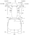
- FIG. 1 shows a tractor which is one of agricultural machines.
- an agricultural machine will be described by taking a tractor as an example, but the agricultural machine may be a combine harvester, a rice transplanter, etc. in addition to the tractor.
- the direction of arrow E1 in FIG. 1 is called the front
- the direction of arrow E2 is called the rear
- the direction of arrow E3 is called the width direction.
- the arrow E4 side may be referred to as the width direction inner side
- the arrow E5 may be referred to as the width direction outer side.
- the tractor 1 includes a vehicle body 3 having a traveling device 7, a prime mover 4, and a transmission 5.
- the traveling device 7 is a device having front wheels 7F and rear wheels 7R.
- the front wheels 7F may be a tire type or a crawler type.
- the rear wheel 7R may also be a tire type or a crawler type.
- the prime mover 4 is an engine (diesel engine, gasoline engine), an electric motor, or the like.
- the speed change device 5 can switch the propulsive force of the traveling device 7 by gear shifting and can switch the traveling device 7 between forward and reverse.
- a driver's seat 10 is provided on the vehicle body 3.
- the driver's seat 10 is protected by a protection device 9.
- the protection device 9 is a cabin that surrounds the front, rear, upper side, and side of the driver's seat 10 to protect the driver's seat 10, and a lops that protects the driver's seat 10 by covering at least the upper part of the driver's seat 10. is there.
- a fender 13 is attached below the protection device 9, and the fender 13 covers the upper portion of the rear wheel 7R.
- the working equipment is a tilling device for tilling, a fertilizer spraying device for spraying fertilizer, a pesticide spraying device for spraying pesticides, a harvesting device for harvesting, a mowing device for cutting grass, etc., a spreading device for spreading grass, etc. And a molding device for molding grass and the like.
- the vehicle body 3 has a plurality of vehicle body frames 20.
- the plurality of vehicle body frames 20 include a vehicle body frame 20L provided on the left side and a vehicle body frame 20R provided on the right side.
- Each of the vehicle body frame 20L and the vehicle body frame 20R extends forward from the transmission 5 side and supports a lower portion of the prime mover 4.
- the body frame 20L and the body frame 20R are separated from each other in the width direction.
- the front end of the vehicle body frame 20L and the front end of the vehicle body frame 20R are connected by a front connecting plate 20F.
- the midway portion of the vehicle body frame 20L and the midway portion of the vehicle body frame 20R are connected by a midway connecting plate 20M.
- the body frame 20L and the body frame 20R support the front axle case 29.
- a front axle 15 (see FIG. 6) that rotatably supports the front wheels 7F is accommodated in the front axle case 29.
- the body frame 20 may be a frame that supports a structure other than the front axle case 29.
- a bonnet 25 is provided on top of the plurality of vehicle body frames 20.
- the bonnet 25 extends in the front-rear direction along the body frame 20.
- the bonnet 25 is arranged in the central portion of the protective device 9 in the width direction.
- the bonnet 25 includes a left side wall 25L provided on the left side, a right side wall 25R provided on the right side, and an upper wall portion connecting the upper parts of the left side wall 25L and the right side wall 25R. 25 U and.
- An engine room is formed by the left side wall 25L, the right side wall 25R, and the upper wall portion 25U, and the engine room accommodates the prime mover 4, a cooling fan, a radiator, a battery, and the like.
- Front wheels 7F are arranged on the left side of the left side wall 25L and the right side of the right side wall 25R, respectively.
- a weight 26 is provided on the front side of the hood 25, that is, on the front side of the vehicle body frames 20L and 20R.
- the weight 26 is attached to a weight bracket 27 that is attached to the front connecting plate 20F with a fastener such as a bolt.
- the tractor 1 includes a steering device 11.
- the steering device 11 includes a steering wheel (steering wheel) 11a, a rotating shaft (steering shaft) 11b that rotates with the rotation of the steering wheel 11a, and an auxiliary mechanism (power steering mechanism) 11c that assists steering of the steering wheel 11a.
- the auxiliary mechanism 11c includes a hydraulic pump 21, a control valve 22 to which hydraulic oil discharged from the hydraulic pump 21 is supplied, and a steering cylinder 23 operated by the control valve 22.
- the control valve 22 is a solenoid valve that operates based on a control signal.
- the control valve 22 is, for example, a three-position switching valve that can be switched by moving a spool or the like.
- the control valve 22 can also be switched by steering the steering shaft 11b.
- the steering cylinder 23 is connected to an arm (knuckle arm) 24 that changes the direction of the front wheels 7F.
- the tractor 1 includes a position detection device 30.
- the position detection device 30 is mounted on the top plate of the protection device 9. Although the position detection device 30 is mounted on the top plate of the protection device 9, the mounting position on the vehicle body 3 is not limited and may be another position. Further, the position detection device 30 may be attached to the work device.
- the position detection device 30 is a device that detects its own position (positioning information including latitude and longitude) by a satellite positioning system. That is, the position detection device 30 receives a signal (position of the positioning satellite, transmission time, correction information, etc.) transmitted from the positioning satellite, and detects the position (latitude, longitude) based on the received signal.
- the position detection device 30 may detect a position corrected based on a signal such as a correction from a base station (reference station) capable of receiving a signal from a positioning satellite as its own position (latitude, longitude).
- the position detection device 30 may have an inertial measurement device such as a gyro sensor or an acceleration sensor, and the position corrected by the inertial measurement device may be detected as its own position. According to the position detection device 30 described above, the position (travel position) of the tractor 1 (vehicle body 3) can be detected by the position detection device 30.
- the tractor 1 includes a control device 40.
- the control device 40 includes a CPU, an electric circuit, an electronic circuit, and the like, and performs various controls of the tractor 1.
- a state detection device 41 that detects the drive state of the tractor 1 and the like is connected to the control device 40.
- the state detection device 41 is, for example, a device that detects the state of the traveling system, and is, for example, a state of a crank sensor, a cam sensor, an engine rotation sensor, an accelerator sensor, a vehicle speed sensor, a steering angle sensor, a position detection device 30), or the like. To detect.
- the state detection device 41 may be a lift lever detection sensor, a PTO rotation detection sensor, or the like, other than the traveling system state.
- the control device 40 controls the traveling system and work system of the tractor 1.
- the control device 40 controls, for example, the engine speed, the vehicle speed, the steering angle of the steering device 11, and the like based on the detection state detected by the state detection device 41.
- the state detection device 41 controls the elevating device for elevating and lowering the connecting portion, the PTO rotation speed, and the like based on the detection state detected by the state detection device 41.
- the control device 40 can control automatic traveling of the tractor 1 (vehicle body 3) (automatic traveling control).
- the control device 40 can switch between an automatic traveling mode and a manual traveling mode.
- the control device 40 causes the traveling position of the vehicle body 3 (the position detected by the position detecting device 30) to at least coincide with the preset traveling route (traveling route), that is, the vehicle body.
- the switching position and the opening degree of the control valve 22 are set so that 3 and the traveling route match.
- the control device 40 sets the moving direction and the moving amount of the steering cylinder 35 (the steering direction and the steering angle of the front wheels 7F) so that the traveling position of the tractor 1 and the traveling route match. Set.
- the control device 40 compares the traveling position of the vehicle body 3 with the position (scheduled traveling position) indicated by the traveling route, and determines that the traveling position and the traveling planned position match.
- the steering angle and the steering direction of the steering wheel 11a in the steering device 11 are maintained without being changed (the opening degree of the control valve 22 and the switching position are maintained without being changed).
- the control device 40 sets the steering angle and the steering angle of the steering wheel 11a in the steering device 11 so that the deviation (deviation amount) between the traveling position and the planned traveling position becomes zero. And/or the steering direction is changed (the opening degree of the control valve 22 and/or the switching position is changed).
- the control device 40 changes the steering angle of the steering device 11 based on the deviation between the traveling position and the planned traveling position in the automatic traveling control.
- the control device 40 may set the steering angle so that the vehicle body azimuth coincides with the azimuth of the traveling route. Further, the control device 40 sets the final steering angle in the automatic traveling control based on the steering angle obtained based on the deviation (positional deviation) and the steering angle obtained based on the azimuth deviation in the automatic traveling control. You may.
- the setting of the steering angle in the automatic travel control in the above-described embodiment is an example, and is not limited.
- the control device 40 causes the traveling device 7, that is, the front wheels 7F and/or the traveling device 7, so that the actual vehicle speed of the tractor 1 (the vehicle body 3) matches the vehicle speed corresponding to the preset traveling route.
- the rotation speed of the rear wheel 7R may be controlled.
- the control device 40 controls the automatic traveling based on the detection result of the obstacle in the obstacle detection device 45 described later. For example, if the obstacle detection device 45 does not detect an obstacle, the automatic traveling is continued, and if the obstacle detection device 45 detects an obstacle, the automatic traveling is stopped. More specifically, when the obstacle detection device 45 detects an obstacle, the control device 40 stops the tractor 1 when the distance between the obstacle and the tractor 1 is less than or equal to a predetermined distance. This stops automatic driving.
- the tractor 1 includes a plurality of obstacle detection devices 45.
- Each of the plurality of obstacle detection devices 45 can detect an object existing around the tractor 1, that is, an obstacle.
- At least one of the plurality of obstacle detection devices 45 is provided in front of the protection device 9 and outside the hood 25 in the width direction. That is, when focusing on a region (front region) A1 in front of the protection device 9 of the tractor 1, at least one obstacle detection device 45 has a region outside the left side wall 25L of the hood 25 in the width direction (outer region). A2 or a region (outer region) A2 outside the right side wall 25R of the bonnet 25 in the width direction.
- the obstacle detection device 45 Is provided on the outer side in the width direction with respect to the outer portion 7F2. In other words, the obstacle detection device 45 is provided outside the front wheel 7F.
- the obstacle detection device 45 is provided in front of the front wheel 7F.
- the obstacle detection device 45 is a laser scanner 45A, a sonar 45B, or the like.
- the laser scanner 45A detects an object (obstacle) by irradiating a laser.
- the laser scanner 45A includes a light emitting/receiving unit 45A1 and a housing 45A2.
- the light emitting/receiving unit 45A1 irradiates the laser and receives the reflected light reflected by the radiated laser when it hits an obstacle.
- the housing 45A2 is a case that houses the light projecting/receiving unit 45A1.
- the laser scanner 45A detects the distance to the obstacle based on the time from the laser irradiation to the light reception.
- the SONAR 45B detects an object (obstacle) by emitting a sound wave.
- the sonar 45B includes a sound receiving/sending unit 45B1 and a housing 45B2.
- the sound projecting/receiving unit 45B1 emits a sound wave, and receives a reflected sound that the sound wave emitted hits an obstacle and is reflected.
- the housing 45B2 is a case that houses the sound receiving and receiving unit 45B1.
- the sonar 45B detects the distance to the obstacle based on the time from the irradiation of the sound wave to the reception of the reflected sound.
- the laser scanner 45A is disposed in front of the front wheel 7F and outside the outer portion 7F2 of the front wheel 7F in the width direction. More specifically, in the laser scanner 45A, the light projecting/receiving unit 45A1 is arranged in front of the front wheel 7F and outside the outer portion 7F2 in the width direction.
- the light emitting/receiving unit 45A1 of the laser scanner 45A is installed at a position lower than the upper end 7F3 of the front wheel 7F. That is, the light emitting and receiving portion 45A1 is located below the upper wall portion 25U of the bonnet 25 and above the front axle 15.
- the sonar 45B is provided in front of the front wheel 7F and between the inner portion 7F1 of the front wheel 7F and the side wall (left side wall 25L, right side wall 25R) of the hood 25. More specifically, in the sonar 45B, the sound receiving and receiving portion 45B1 is provided in front of the front wheel 7F and between the inner portion 7F1 and the side wall of the bonnet 25. In other words, as shown in FIG. 3B, the projected range between the inner portion 7F1 of the front wheel 7F and the side wall of the bonnet 25 (the left side wall 25L, the right side wall 25R) is projected toward the front of the front wheel 7F.
- the sonar 45B is provided in the (projection range G1).
- the obstacle detection device 45 is supported by the vehicle body 3 by a support mechanism 50.
- the support mechanism 50 is a fixing mechanism that fixes the obstacle detection device 45 to the vehicle body 3 such that the position of the obstacle detection device 45 cannot be changed.
- the support mechanism 50 includes a left support body 51 attached to the front portion of the vehicle body frame 20L and protruding forward, and a left support arm 52 extending outward in the width direction from the left support body 51 to the left side.
- the left support body 51 includes a mounting plate 51a attached to the vehicle body frame 20L, an extending plate 51b that moves outward in the width direction as it goes forward from the mounting plate 51a, and extends forward from the extending plate 51b.
- the mounting plate 51c to which the support arm 52 is mounted is included.
- the mounting plate 51c is located on the left side (left side) of the weight 26.
- the left support arm 52 is a metal member formed in a rectangular tube shape. One end of the left support arm 52 is attached to the mounting plate 51c, and the other end of the left support arm 52 is a free end. The free end side of the left support arm 52 is located on the outer side 7F2 side of the left wheel 7F, and the laser scanner 45A is attached via the bracket 55. A bracket 55 is attached to the free end side of the left support arm 52, and the housing 45A2 of the laser scanner 45A is attached to the bracket 55.
- the bracket 55 supports the housing 45A2 so that the irradiation line L1 is in the horizontal direction.
- the bracket 55 supports the housing 45A2 so that the upper surface of the housing 45A2 and the upper portion of the left support arm 52 are parallel to each other.
- a bracket 56 is attached to the middle of the left support arm 52, and the housing 45B2 of the sonar 45B is attached to the bracket 56.
- the left support arm 52 supports the laser scanner 45A, which is one of the obstacle detection devices 45, in front of the protection device 9 and on the left outside in the width direction of the hood 25, and the weight. It is supported on the left side of 26.
- the left support arm 52 supports not only the laser scanner 45A but also the sonar 45B on the left side of the weight 26. That is, as shown in FIG. 3B, the left support arm 52 is disposed on the left side of the weight 26, and is provided behind the front end portion 26F of the weight 26.
- the obstacle detection device 45 (laser scanner 45A and sonar 45B) is arranged on the left side of the weight 26 and behind the front end portion 26F of the weight 26, similarly to the left support arm 52. More specifically, on the left side of the weight 26, the left support arm 52 and the obstacle detection device 45 (laser scanner 45A and sonar 45B) are provided in a region A10 between the front end portion 26F and the rear end portion of the weight 26. ing.
- the support mechanism 50 includes a right support body 53 that is attached to the front portion of the vehicle body frame 20R and projects forward, and a right support arm 54 that extends outward from the right support body 53 in the width direction and extends to the right. There is.
- the right support 53 and the right support arm 54 support the obstacle detection device 45 on the opposite side of the left support 51 and the left support arm 52.
- the structures of the right support body 53 and the right support arm 54 are the same as the left support body 51 and the left support arm 52.
- the right support body 53 includes a mounting plate 53a attached to the vehicle body frame 20R, an extending plate 53b that moves outward in the width direction as it goes forward from the mounting plate 53a, and extends forward from the extending plate 53b. And a mounting plate 53c to which the support arm 54 is mounted.
- the mounting plate 53c is located on the right side (right side) of the weight 26.
- the right support arm 54 is a metal member formed in a rectangular tube shape. One end of the right support arm 54 is attached to the mounting plate 53c, and the other end of the right support arm 54 is a free end. The free end side of the right support arm 54 is located on the outer side 7F2 side of the right wheel 7F, and the laser scanner 45A is attached via the bracket 57.
- a bracket 57 is attached to the free end side of the right support arm 54, and the housing 45A2 of the laser scanner 45A is attached to the bracket 57.
- the bracket 57 supports the housing 45A2 so that the irradiation line L1 in the light projecting/receiving unit 45A1 is horizontal. In other words, the bracket 57 supports the housing 45A2 so that the upper surface of the housing 45A2 and the upper portion of the right support arm 54 are parallel to each other.
- a bracket 58 is attached to the middle of the right support arm 54, and the housing 45B2 of the sonar 45B is attached to the bracket 58.
- the right support arm 54 supports the laser scanner 45A, which is one of the obstacle detection devices 45, in front of the protection device 9 and on the right outside in the width direction of the bonnet 25, and the weight. It is supported on the right side of 26.
- the right support arm 54 supports not only the laser scanner 45A but also the sonar 45B on the right side of the weight 26. That is, as shown in FIG. 3B, the right support arm 54 is disposed on the right side of the weight 26, and is provided behind the front end portion 26F of the weight 26.
- the obstacle detection device 45 (laser scanner 45A and sonar 45B) is arranged on the right side of the weight 26 and is provided behind the front end portion 26F of the weight 26, similarly to the right support arm 54. More specifically, on the right side of the weight 26, the right support arm 54 and the obstacle detection device 45 (laser scanner 45A and sonar 45B) are provided in the area A11 between the front end portion 26F and the rear end portion of the weight 26. ing.
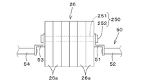
- the left support body 51 and the right support body 53 are attached to the vehicle body frame 20 to support the support arms (the left support arm 52 and the right support arm 54), but they are attached to the weight 26. It may be a structure.
- the weight 26 includes a plurality of individual plates 26a and a connector 250 that connects the plurality of individual plates 26a.
- the connecting tool 250 includes a rod member 251 such as a bolt that can be inserted into holes formed in the plurality of individual plates 26a, and a retaining member 252 such as a nut that prevents the rod member 251 from coming off.
- the left support body 51 and the right support body 53 have insertion holes into which the rods 251 are inserted, and are fixed (supported) to the weight 26 by being fastened together with the plurality of individual plates 26a.
- the brackets 55 to 58 may be hook type (hook type).
- the brackets 55 to 58 have a hooking portion 260 that hooks on the outer surface of the support arm (the left support arm 52, the right support arm 54), and the hooking portion 260 includes a fastener such as a bolt.
- An insertion hole for inserting 261 is formed.
- the support arm (the left support arm 52, the right support arm 54) is formed with a fastening hole into which the fastener 261 is inserted and fastened. Therefore, the obstacle detection device 45 (laser scanner 45A and sonar 45B) can be easily attached by hooking the hooking portion 260 of the brackets 55 to 58 to the support arm and fastening the fastener 261 to the support arm. it can.
- the agricultural machine includes the vehicle body 3 having the front wheels 7F and the rear wheels 7R, the bonnet 25 provided on the front side of the vehicle body 3, the protective device 9 provided on the vehicle body 3 and protecting the driver's seat 10.
- An obstacle detection device 45 capable of detecting an obstacle, which is provided in front of the protection device 9 and outside the width direction of the hood 25, is provided. According to this, for example, in an agricultural machine such as the tractor 1, an obstacle around the hood 25 located in front of the protection device 9 can be easily and accurately detected by the obstacle detection device 45. For example, even if the agricultural machine is provided with a structure projecting outward in the width direction from the bonnet 25, the obstacle detection device 45 can detect the state around the structure.
- the obstacle detection device 45 is provided on the side of the front wheel 7F, that is, on the outer side in the width direction or the inner side in the width direction. According to this, as shown in FIG. 1, in the agricultural machine, the obstacle existing in the side area A20 of the front wheel 7F and the front area A21 of the front wheel 7F can be accurately detected. Particularly, when the laser scanner 45A is provided on the side of the front wheel 7F as the obstacle detection device 45, the obstacle detection device 45 can detect a wide range of obstacles from the front part to the rear part of the vehicle body 3. ..
- the obstacle detection device 45 is provided in front of the front wheel 7F. According to this, the obstacle existing around the front wheel 7F can be accurately detected by the obstacle detection device 45. For example, when the size of the front wheel 7F is large, the obstacles around the front wheel 7F can be detected more than the obstacle detection device mounted on the protection device 9 behind the front wheel 7F.
- the obstacle detection device 45 is provided in front of the front wheel 7F and between the bonnet 25 and the front wheel 7F, that is, within the widthwise range (projection range G1) between the bonnet 25 and the front wheel 7F in front of the front wheel 7F. Has been. According to this, the obstacle existing between the hood 25 and the front wheel 7F can be detected more accurately by the obstacle detection device 45.
- the agricultural machine includes body frames 20L and 20R that support the hood 25, and support arms (left support arm 52 and right support arm 54) that extend outward from the body frames 20L and 20R in the width direction and that support the obstacle detection device 45. , Are provided. According to this, the obstacle detection device 45 can be firmly supported by the support arms (the left support arm 52, the right support arm 54).
- the agricultural machine includes a weight 26 provided on the front side of the hood 25, and the obstacle detection device 45 is provided on the lateral side of the weight 26. According to this, the obstacle detecting device 45 can accurately detect an obstacle existing around the weight 26.
- the obstacle detection device 45 is provided in front of the protection device 9 in the above-described embodiment, the obstacle detection device 45 may be provided at a position other than the front of the protection device 9.
- FIG. 7 shows a modification of the arrangement of the obstacle detection device 45. As shown in FIG. 7, the laser scanner 45A may be provided in the rear part of the protection device 9, or the sonar 45B may be provided in the left part and the right part of the protection device 9. Further, as shown in FIG.
- sonars 45B may be provided on both sides of the laser scanner 45A in front of the front wheels 7F. Further, in front of the front wheel 7F, the laser scanner 45A or the sonar 54B may be provided in the facing range A22 facing the tread portion 7F4 of the front wheel 7F.
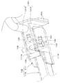
- the obstacle detection device 45 is fixed to the vehicle body 3 by the support mechanism 50 in the above-described embodiment, instead of this, as shown in FIGS. 8 to 11, the agricultural machine such as the tractor 1 has obstacles.
- a position changing mechanism 80 that can change the position of the detection device 45 may be provided. 8 to 11 show a case where a position changing mechanism 80 that can change the position of the obstacle detecting device 45 provided in front of the protection device 9 and outside the width direction of the bonnet 25 is provided. There is.
- the position changing mechanism 80 changes the position of the obstacle detection device 45 between a detection position Q1 that is a predetermined position for detecting an obstacle and a retracted position Q2 that retracts from the detected position Q1 to the vehicle body 3 side.
- the position changing mechanism 80 is provided on the left side and the right side of the front part of the tractor 1.
- the position changing mechanism 80 provided on the right side of the front portion of the tractor 1 will be described as an example.
- the position changing mechanism 80 provided on the left side of the front part of the tractor 1 has the same structure as the position changing mechanism 80 provided on the right side.
- the position changing mechanism 80 has a first support arm 101 and a second support arm 102.
- the first support arm 101 is a support arm fixed to the vehicle body 3, and the second support arm 102 is a support arm rotatably supported with respect to the first support arm 101. That is, the position changing mechanism 80 includes a support arm that supports the obstacle detection device 45, and the position of the support arm can be changed.
- the first support arm 101 includes a front plate portion 101F and a rear plate portion 101R arranged rearward from the front plate portion 101F, and the front plate portion 101F and the rear plate portion 101F are provided.
- the left end portion of the plate portion 101R is fixed to the mounting plate 53c.
- Through holes penetrating in the thickness direction are formed in the front plate portion 101F and the rear plate portion 101R, and the rotating shaft 105 is inserted into the through holes.
- the front plate portion 101F and the rear plate portion 101R are formed with through holes different from the through holes into which the rotating shaft 105 is inserted, and the lock pin 103 can be inserted into the other through holes. is there.
- the lock pin 103 is a pin that can be inserted into and removed from the through hole.
- the second support arm 102 has a mounting portion 110 and a rotating portion 111.
- the attachment part 110 is a tubular member made of metal and to which the obstacle detection device 45 is attached.
- a bracket 57 is provided at the tip portion (free end side) of the attachment portion 110, and the housing 45A2 of the laser scanner 45A is attached thereto.
- a bracket 58 is attached to an intermediate portion of the attachment portion 110, and the housing 45B2 of the sonar 45B is attached to the bracket 58.
- the rotating portion 111 is a portion that is connected to the mounting portion 110 and rotates around the rotating shaft 105 with respect to the front plate portion 101F and the rear plate portion 101R.
- the rotating portion 111 includes a front plate portion 111F and a rear plate portion 111R.
- the attachment portion 110 is fixed to the right end portions of the front plate portion 111F and the rear plate portion 111R.
- through holes penetrating in the thickness direction are formed in the front plate portion 111F and the rear plate portion 111R, and the rotating shaft 105 is inserted into the through holes.
- a through hole 115 different from the through hole into which the rotating shaft 105 is inserted is formed in the front plate portion 111F and the rear plate portion 111R, and the lock pin 103 is inserted into the other through hole 115. It is possible.
- another through hole 115 is provided in at least two places, and when the lock pin 103 is inserted into one through hole 115a, the rotating portion 111 (mounting portion 110). Is held in the detection posture, and when the lock pin 103 is inserted into the other through hole 115b, the rotating portion 111 (mounting portion 110) is held in the retracted posture. That is, when the second support arm 102 is in the detection posture, the second support arm 102 is horizontally held by the first support arm 101 and positions the obstacle detection device 45 (laser scanner 45A and sonar 45B) at the detection position Q1.
- the obstacle detection device 45 laser scanner 45A and sonar 45B
- the second support arm 102 when the second support arm 102 is in the retracted posture, the second support arm 102 is vertically held by the first support arm 101 to position the obstacle detection device 45 (laser scanner 45A and sonar 45B) at the retracted position Q2.
- the obstacle detection device 45 (the laser scanner 45A and the sonar 45B) is located inside the outside portion 7F2 of the front wheel 7F in the width direction. That is, at the retracted position Q2, the irradiation line L1 is oriented vertically (vertically), and is not in the posture of detecting an obstacle. That is, the position changing mechanism 80 retracts the obstacle detection device 45 (laser scanner 45A and sonar 45B) to the retracted position Q2 that is not used.
- the position changing mechanism 80 includes a first posture detection device 130 that detects the detected posture of the second support arm 102 and a second posture detection device that detects the retracted posture of the second support arm 102. It has a posture detection device 131.
- the first posture detection device 130 detects that the second support arm 102 is in the detection posture when the detection plate 132 provided over the front plate portion 101F and the rear plate portion 101R contacts the first posture detection device 130.
- the second support arm 102 is in the retracted attitude when the detection plate 133 provided at the base end portion (on the attachment plate 53C side) of the attachment portion 110 contacts the second attitude detection device 131. Detect that.
- the detection information of the first attitude detection device 130 and the second attitude detection device 131 is input to the control device 40.
- the control device 40 displays, for example, the detection information of the first attitude detection device 130 and the second attitude detection device 131 on the display device 70 (see FIG. 6) provided near the driver's seat 10 or starts automatic traveling. In such a case, the control is performed such that the automatic traveling is permitted in the case of the detected posture and the automatic traveling is not permitted in the case of the retracted posture.
- the position changing mechanism 80 changes the position of the obstacle detection device 45 between a detection position Q1 that is a predetermined position for detecting an obstacle and a retracted position Q2 that retracts from the detected position Q1 to the vehicle body 3 side.
- the obstacle detection device 45 can be arranged at the detection position Q1 which is a predetermined position capable of detecting over a wide area with as few blind spots as possible, while at the retracted position Q2 where it does not interfere. Can be placed. That is, by making the position of the obstacle detection device 45 changeable between the detection position Q1 and the retracted position Q2, the obstacle detection device 45 can be arranged at a position where the detection accuracy is improved as much as possible.
- the position change mechanism 80 sets the obstacle detection device 45 to the detection position Q1 so that the obstacle detection device 45 detects the presence of the obstacle and the automatic traveling is performed. it can.
- the obstacle detection device 45 is set to the retracted position Q2 by the position changing mechanism 80, so that the manual traveling can be performed without the detection by the obstacle detection device 45.
- the position changing mechanism 80 has a first support arm 101 fixed to the vehicle body 3 and a second support arm 102 rotatably supported with respect to the first support arm 101. According to this, the position of the obstacle detection device 45 can be easily changed to the detection position Q1 and the retracted position Q2 simply by rotating the second support arm 102 with respect to the first support arm 101. By the way, in the above-described embodiment, the position changing mechanism 80 changes the position of the obstacle detection device 45 between the detection position Q1 and the retracted position Q2, but changes the position of the obstacle detection device 45 to a plurality of detection positions Q1. You may.
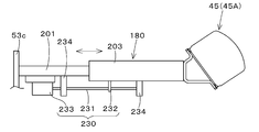
- FIG. 13 shows a position changing mechanism 180 for changing the position of the obstacle detection device 45 to a plurality of detection positions Q1.
- the position changing mechanism 180 has a first support arm 201 fixed to the vehicle body and a third support arm 203 movable in the longitudinal direction of the first support arm 201.
- the first support arm 201 is a metal member formed in a tubular shape, and one end thereof is fixed to the mounting plate 53c.
- the third support arm 203 is a metal member formed in a tubular shape, and like the second support arm 102, the bracket 57 and the bracket 58 are attached thereto, and the laser scanner 45A and the sonar 45B are attached thereto, respectively. There is.
- One end side (the side opposite to the free end) of the third support arm 203 is inserted into the first support arm 201, and the position with respect to the first support arm 201 can be changed. More specifically, when the third support arm 203 is inserted into the first support arm 201, the third support arm 203 includes a laser scanner 45A and a sonar 45A so that the irradiation line L1 of the laser scanner 45A and the sonar 45B is substantially horizontal. Holds Sonar 45B.
- Each of the first support arm 201 and the second support arm 102 has a plurality of through holes 202 formed at predetermined intervals in the longitudinal direction (width direction), and the lock pin 213 can be inserted into the through holes 202. Is.
- the position of the lock pin 213 with respect to the first support arm 201 can be changed. It can be fixed (held), and the position of the laser scanner 45A and the sonar 45B in the width direction, that is, the position of the detection position Q1 can be changed by changing the through hole 202 into which the lock pin 213 is inserted.
- the position changing mechanism 180 has a configuration in which the position of the third support arm 203 with respect to the first support arm 201 is changed by the lock pin 213, but other configurations may be used.
- FIG. 14A shows an example of position change by the cylinder 220
- FIG. 14B shows an example of position change by the feed screw mechanism 230.
- the cylinder 220 can be expanded and contracted by a medium such as air and hydraulic pressure
- the rod 220 a is attached to the third support arm 203 via a bracket 221
- the tube 220 b is attached to the first support arm 201. Is attached to the bracket via a bracket 222.
- the obstacle detection device 45 can be repositioned to an arbitrary detection position Q1 by the expansion and contraction of the cylinder 220.
- the feed screw mechanism 230 includes a feed screw 231, a moving body 232, and a motor 233.
- the feed screw 231 is arranged along the first support arm 201 and the third support arm 203, and both ends thereof are rotatably attached to the first support arm 201 and the third support arm 203 by bearings 234.
- the moving body 232 is screwed onto the feed screw 231 and is fixed to the third support arm 203.
- the motor 233 is fixed to the first support arm 201 and rotates the feed screw 231. According to this, by rotating the feed screw 231 in the normal direction or the reverse direction by the motor 233, the position of the obstacle detection device 45 can be changed to the arbitrary detection position Q1.
- a plurality of detection positions Q1 may be registered in the tractor 1, and a predetermined detection position Q1 may be selected from the plurality of registered detection positions Q1.
- a predetermined detection position Q1 may be selected from the plurality of registered detection positions Q1.
- the detection positions Q1 on the left side and the right side are registered in either the control device 40 or the display device 70.
- J1, J2... Indicate the detection position Q1 by a symbol for convenience of description, and if the symbol is different, it means that the detection position Q1 is different.
- a list of registered detection positions Q1 is displayed on the display device 70, and the operator operates the display device 70 to set a plurality of detection positions Q1 to agricultural work, agricultural machinery, or Select according to the working device (implement).
- the position changing mechanism 180 positions the obstacle detection device 45 at the detection position Q1 selected by the display device 70 or the like.
- the position changing mechanism 180 may automatically change the detection position Q1 according to the width of the working device (implement) mounted on the tractor 1.
- the position changing mechanism 180 changes the position of the obstacle detection device 45 to a plurality of detection positions Q1 capable of detecting the obstacle. According to this, since the detection position Q1 can be changed in the obstacle detection device 45, for example, the positions in the width direction of the side area A20 and the front area A21 of the front wheel 7F shown in FIG. 1 can be changed. You can That is, the positions in the width direction of the side area A20 and the front area A21 of the front wheels 7F can be changed according to various situations, and the detection area (side) can be changed according to the specifications (type) of the agricultural machine or the agricultural work. By changing the direction area A20 and the front air A21), the obstacle can be detected more accurately.
- the position changing mechanism 180 has a first support arm 201 fixed to the vehicle body 3 and a third support arm 203 movable in the longitudinal direction of the first support arm 201. According to this, the position of the obstacle detection device 45 can be easily changed by the support arms (the first support arm 201 and the third support arm 203).
- the position changing mechanisms 80 and 180 are also applicable to other obstacle detecting devices 45 provided in addition to the obstacle detecting device 45 provided on the side of the bonnet 25 or on the front wheel 7F. Further, it is also applicable to a tractor in which the obstacle detection device 45 is not provided on the side of the hood 25 or the front wheel 7F.
- the tractor 1 in which the obstacle detection device 45 is provided around the protection device 9 may be provided with the position changing mechanisms 80 and 180, or the position may be changed to the conventional tractor 1 disclosed in JP-A-2018-174890.
- Mechanisms 80, 180 may be provided.
- the fixed side support arms (first support arms 101 and 201) may be attached to the left support body 51 and the right support body 53 mounted on the weight 26 as in FIG. ..
- the brackets 55 to 58 having the hook portions 260 are hooked on the moving-side supporting arms (the second supporting arm 102 and the third supporting arm 203) to move the fastener 261 to the moving side. It may be attached to the support arm.
- tractor 3 vehicle body 7F: front wheel 7R: rear wheel 9: protective device 10: driver's seat 20: vehicle body frame 26: weight 40: control device 45: obstacle detection device 50: support mechanism 80: position change mechanism 101, 201 : First support arm 102: second support arm 203: third support arm Q1: detection position Q2: retracted position
Landscapes
- Engineering & Computer Science (AREA)
- Physics & Mathematics (AREA)
- Radar, Positioning & Navigation (AREA)
- Remote Sensing (AREA)
- General Physics & Mathematics (AREA)
- Life Sciences & Earth Sciences (AREA)
- Mechanical Engineering (AREA)
- Aviation & Aerospace Engineering (AREA)
- Automation & Control Theory (AREA)
- Computer Networks & Wireless Communication (AREA)
- Soil Sciences (AREA)
- Environmental Sciences (AREA)
- Acoustics & Sound (AREA)
- Electromagnetism (AREA)
- Optics & Photonics (AREA)
- Chemical & Material Sciences (AREA)
- Combustion & Propulsion (AREA)
- Transportation (AREA)
- Guiding Agricultural Machines (AREA)
- Control Of Position, Course, Altitude, Or Attitude Of Moving Bodies (AREA)
Abstract
The present invention makes it possible to more accurately detect obstacles around a vehicle body. This agricultural machinery is equipped with: a vehicle body (3) that has front wheels (7F) and rear wheels (7R); an obstacle detection device (45) that can detect an obstacle; and a position changing mechanism (80) that can change the position of the obstacle detection device (45). The position changing mechanism (80) changes the position of the obstacle detection device (45) to a detection position (Q1) that is a preset position for detecting an obstacle, and to a retraction position (Q2) at which the position detection device (45) is retracted from the detection position (Q1) toward the vehicle body. The position changing mechanism (80) changes the position of the obstacle detection device (45) to a plurality of detection positions (Q1) at which it is possible to detect an obstacle.
Description
本発明は、例えば、トラクタ、コンバイン、田植機等の農業機械に関する。
The present invention relates to agricultural machines such as tractors, combine harvesters, and rice transplanters.
従来、特許文献1に開示されたトラクタが知られている。
特許文献1に開示のトラクタは、車体を自動で運転する自動運転用の電子制御システムと、障害物の有無を検出する障害物検出モジュールと、障害物検出モジュールが障害物を検出する車体の走行を抑制する走行抑制制御部と、探査対象領域に存在する障害物を検出する複数の障害物探査器とを備えている。 Conventionally, the tractor disclosed inPatent Document 1 is known.
The tractor disclosed inPatent Document 1 is an electronic control system for automatic driving that automatically drives a vehicle body, an obstacle detection module that detects the presence or absence of an obstacle, and a vehicle body traveling that the obstacle detection module detects an obstacle. And a plurality of obstacle searchers that detect obstacles existing in the search target area.
特許文献1に開示のトラクタは、車体を自動で運転する自動運転用の電子制御システムと、障害物の有無を検出する障害物検出モジュールと、障害物検出モジュールが障害物を検出する車体の走行を抑制する走行抑制制御部と、探査対象領域に存在する障害物を検出する複数の障害物探査器とを備えている。 Conventionally, the tractor disclosed in
The tractor disclosed in
特許文献1に開示のトラクタにあっては、複数の障害物探査器によって、車体の周囲に存在する障害物を検出することができる。近年では、トラクタにおいて、障害物探査器が車体の周囲に存在する障害物に対して精度良く検出することが、より求められている。
そこで、本発明は、より精度よく車体の周囲に存在する障害物を検出することができる農業機械を提供することを目的とする。 In the tractor disclosed inPatent Document 1, an obstacle existing around the vehicle body can be detected by the plurality of obstacle searchers. In recent years, in a tractor, there is a demand for an obstacle probe to accurately detect an obstacle existing around a vehicle body.
Therefore, an object of the present invention is to provide an agricultural machine capable of detecting an obstacle existing around a vehicle body with higher accuracy.
そこで、本発明は、より精度よく車体の周囲に存在する障害物を検出することができる農業機械を提供することを目的とする。 In the tractor disclosed in
Therefore, an object of the present invention is to provide an agricultural machine capable of detecting an obstacle existing around a vehicle body with higher accuracy.
本発明の農業機械は、前輪及び後輪を有する車体と、障害物を検出可能な障害物検出装置と、前記障害物検出装置の位置を変更可能な位置変更機構と、を備えている。
前記位置変更機構は、前記障害物検出装置を、予め定められた位置であって障害物を検出する検出位置と、前記検出位置から前記車体側に退避する退避位置とに位置変更する。
前記位置変更機構は、前記障害物検出装置を、前記障害物を検出可能な複数の検出位置に位置変更する。 The agricultural machine of the present invention includes a vehicle body having front wheels and rear wheels, an obstacle detection device capable of detecting an obstacle, and a position changing mechanism capable of changing the position of the obstacle detection device.
The position changing mechanism changes the position of the obstacle detection device between a detection position that is a predetermined position for detecting an obstacle and a retracted position that retracts from the detection position to the vehicle body side.
The position changing mechanism changes the position of the obstacle detection device to a plurality of detection positions capable of detecting the obstacle.
前記位置変更機構は、前記車体に固定された第1支持アームと、前記第1支持アームに対して回動自在に支持された第2支持アームとを有している。
前記位置変更機構は、前記車体に固定された第1支持アームと、前記第1支持アームの長手方向に移動可能な第3支持アームとを有している。
前記第1支持アームは、前記車体から当該車体の幅方向外側に延設されている。 The position changing mechanism has a first supporting arm fixed to the vehicle body and a second supporting arm rotatably supported with respect to the first supporting arm.
The position changing mechanism has a first support arm fixed to the vehicle body and a third support arm movable in the longitudinal direction of the first support arm.
The first support arm extends from the vehicle body to the outside in the width direction of the vehicle body.
農業機械は、前記車体の自動走行を制御する制御装置を備え、前記制御装置は、前記障害物検出装置における障害物の検出結果に基づいて前記自動走行を制御する。
The agricultural machine includes a control device that controls the automatic traveling of the vehicle body, and the control device controls the automatic traveling based on the detection result of the obstacle in the obstacle detection device.
上記の構成によれば、より精度よく車体の周囲に存在する障害物を検出することができる。
According to the above configuration, it is possible to detect the obstacles existing around the vehicle body more accurately.
以下、本発明の実施の形態を図面に基づいて説明する。
図1は、農業機械の1つであるトラクタを示している。この実施形態では、トラクタを例にとり農業機械について説明するが、農業機械は、トラクタの他、コンバイン、田植機等であってもよい。なお、説明の便宜上、図1の矢印E1の方向を前方、矢印E2の方向を後方、矢印E3の方向を幅方向という。幅方向E3において、矢印E4側を幅方向内側、矢印E5を幅方向外側ということがある。 Embodiments of the present invention will be described below with reference to the drawings.
FIG. 1 shows a tractor which is one of agricultural machines. In this embodiment, an agricultural machine will be described by taking a tractor as an example, but the agricultural machine may be a combine harvester, a rice transplanter, etc. in addition to the tractor. For convenience of explanation, the direction of arrow E1 in FIG. 1 is called the front, the direction of arrow E2 is called the rear, and the direction of arrow E3 is called the width direction. In the width direction E3, the arrow E4 side may be referred to as the width direction inner side, and the arrow E5 may be referred to as the width direction outer side.
図1、図2に示すように、トラクタ1は、走行装置7を有する車体3と、原動機4と、変速装置5とを備えている。走行装置7は、前輪7F及び後輪7Rを有する装置である。前輪7Fは、タイヤ型であってもクローラ型であってもよい。また、後輪7Rも、タイヤ型であってもクローラ型であってもよい。原動機4は、エンジン(ディーゼルエンジン、ガソリンエンジン)、電動モータ等である。変速装置5は、変速によって走行装置7の推進力を切換可能であると共に、走行装置7の前進、後進の切換が可能である。車体3には、運転席10が設けられている。運転席10は、保護装置9により保護されている。保護装置9は、運転席10の前方、後方、上方及び側方を取り囲むことにより当該運転席10を保護するキャビン、少なくとも運転席10の上方を覆うことにより当該運転席10を保護するロプス等である。保護装置9の下方には、フェンダ13が取り付けられており、フェンダ13は後輪7Rの上部を覆っている。
As shown in FIGS. 1 and 2, the tractor 1 includes a vehicle body 3 having a traveling device 7, a prime mover 4, and a transmission 5. The traveling device 7 is a device having front wheels 7F and rear wheels 7R. The front wheels 7F may be a tire type or a crawler type. Further, the rear wheel 7R may also be a tire type or a crawler type. The prime mover 4 is an engine (diesel engine, gasoline engine), an electric motor, or the like. The speed change device 5 can switch the propulsive force of the traveling device 7 by gear shifting and can switch the traveling device 7 between forward and reverse. A driver's seat 10 is provided on the vehicle body 3. The driver's seat 10 is protected by a protection device 9. The protection device 9 is a cabin that surrounds the front, rear, upper side, and side of the driver's seat 10 to protect the driver's seat 10, and a lops that protects the driver's seat 10 by covering at least the upper part of the driver's seat 10. is there. A fender 13 is attached below the protection device 9, and the fender 13 covers the upper portion of the rear wheel 7R.
車体3の後部には、3点リンク機構等で構成された連結部が設けられている。連結部には、作業装置が着脱可能である。作業装置を連結部に連結することによって、車体3によって作業装置を牽引することができる。作業装置は、耕耘する耕耘装置、肥料を散布する肥料散布装置、農薬を散布する農薬散布装置、収穫を行う収穫装置、牧草等の刈取を行う刈取装置、牧草等の拡散を行う拡散装置、牧草等の集草を行う集草装置、牧草等の成形を行う成形装置等である。
At the rear of the vehicle body 3, there is a connecting part made up of a three-point link mechanism. A work device can be attached to and detached from the connecting portion. By connecting the work device to the connecting portion, the work device can be pulled by the vehicle body 3. The working equipment is a tilling device for tilling, a fertilizer spraying device for spraying fertilizer, a pesticide spraying device for spraying pesticides, a harvesting device for harvesting, a mowing device for cutting grass, etc., a spreading device for spreading grass, etc. And a molding device for molding grass and the like.
図1に示すように、車体3は、複数の車体フレーム20を有している。複数の車体フレーム20は、左側に設けられた車体フレーム20Lと、右側に設けられた車体フレーム20Rとを含んでいる。車体フレーム20L及び車体フレーム20Rは、それぞれは変速装置5側から前方に延設されていて、原動機4の下部を支持している。車体フレーム20Lと車体フレーム20Rとは幅方向に離間している。車体フレーム20Lの前端部と車体フレーム20Rの前端部とは、前連結板20Fにより連結されている。車体フレーム20Lの中途部と車体フレーム20Rの中途部とは、中途連結板20Mにより連結されている。車体フレーム20Lと車体フレーム20Rとは、前車軸ケース29を支持している。前車軸ケース29内には、前輪7Fを回転自在に支持する前車軸15(図6参照)が収容されている。なお、車体フレーム20は、前車軸ケース29以外の構造体を支持するフレームであってもよい。
As shown in FIG. 1, the vehicle body 3 has a plurality of vehicle body frames 20. The plurality of vehicle body frames 20 include a vehicle body frame 20L provided on the left side and a vehicle body frame 20R provided on the right side. Each of the vehicle body frame 20L and the vehicle body frame 20R extends forward from the transmission 5 side and supports a lower portion of the prime mover 4. The body frame 20L and the body frame 20R are separated from each other in the width direction. The front end of the vehicle body frame 20L and the front end of the vehicle body frame 20R are connected by a front connecting plate 20F. The midway portion of the vehicle body frame 20L and the midway portion of the vehicle body frame 20R are connected by a midway connecting plate 20M. The body frame 20L and the body frame 20R support the front axle case 29. A front axle 15 (see FIG. 6) that rotatably supports the front wheels 7F is accommodated in the front axle case 29. The body frame 20 may be a frame that supports a structure other than the front axle case 29.
複数の車体フレーム20の上部には、ボンネット25が設けられている。ボンネット25は、車体フレーム20に沿って前後方向に延設されている。ボンネット25は、保護装置9の幅方向の中央部に配置されている。図1、図2に示すように、ボンネット25は、左側に設けられた左側壁25Lと、右側に設けられた右側壁25Rと、左側壁25Lと右側壁25Rとの上部を連結する上壁部25Uとを有している。左側壁25L、右側壁25R及び上壁部25Uによってエンジンルームが形成され、エンジンルームに原動機4、冷却ファン、ラジエータ、バッテリ等を収容している。左側壁25Lの左側方と、右側壁25Rの右側方とには、それぞれ前輪7Fが配置されている。
A bonnet 25 is provided on top of the plurality of vehicle body frames 20. The bonnet 25 extends in the front-rear direction along the body frame 20. The bonnet 25 is arranged in the central portion of the protective device 9 in the width direction. As shown in FIGS. 1 and 2, the bonnet 25 includes a left side wall 25L provided on the left side, a right side wall 25R provided on the right side, and an upper wall portion connecting the upper parts of the left side wall 25L and the right side wall 25R. 25 U and. An engine room is formed by the left side wall 25L, the right side wall 25R, and the upper wall portion 25U, and the engine room accommodates the prime mover 4, a cooling fan, a radiator, a battery, and the like. Front wheels 7F are arranged on the left side of the left side wall 25L and the right side of the right side wall 25R, respectively.
ボンネット25の前側、即ち、車体フレーム20L、20Rの前側には、ウエイト26が設けられている。ウエイト26は、前連結板20Fにボルト等の締結具により取付けられたウエイトブラケット27に取付けられている。
図6に示すように、トラクタ1は、操舵装置11を備えている。操舵装置11は、ハンドル(ステアリングホイール)11aと、ハンドル11aの回転に伴って回転する回転軸(操舵軸)11bと、ハンドル11aの操舵を補助する補助機構(パワーステアリング機構)11cと、を有している。補助機構11cは、油圧ポンプ21と、油圧ポンプ21から吐出した作動油が供給される制御弁22と、制御弁22により作動するステアリングシリンダ23とを含んでいる。制御弁22は、制御信号に基づいて作動する電磁弁である。制御弁22は、例えば、スプール等の移動によって切り換え可能な3位置切換弁である。また、制御弁22は、操舵軸11bの操舵によっても切換可能である。ステアリングシリンダ23は、前輪7Fの向きを変えるアーム(ナックルアーム)24に接続されている。 Aweight 26 is provided on the front side of the hood 25, that is, on the front side of the vehicle body frames 20L and 20R. The weight 26 is attached to a weight bracket 27 that is attached to the front connecting plate 20F with a fastener such as a bolt.
As shown in FIG. 6, thetractor 1 includes a steering device 11. The steering device 11 includes a steering wheel (steering wheel) 11a, a rotating shaft (steering shaft) 11b that rotates with the rotation of the steering wheel 11a, and an auxiliary mechanism (power steering mechanism) 11c that assists steering of the steering wheel 11a. doing. The auxiliary mechanism 11c includes a hydraulic pump 21, a control valve 22 to which hydraulic oil discharged from the hydraulic pump 21 is supplied, and a steering cylinder 23 operated by the control valve 22. The control valve 22 is a solenoid valve that operates based on a control signal. The control valve 22 is, for example, a three-position switching valve that can be switched by moving a spool or the like. The control valve 22 can also be switched by steering the steering shaft 11b. The steering cylinder 23 is connected to an arm (knuckle arm) 24 that changes the direction of the front wheels 7F.
図6に示すように、トラクタ1は、操舵装置11を備えている。操舵装置11は、ハンドル(ステアリングホイール)11aと、ハンドル11aの回転に伴って回転する回転軸(操舵軸)11bと、ハンドル11aの操舵を補助する補助機構(パワーステアリング機構)11cと、を有している。補助機構11cは、油圧ポンプ21と、油圧ポンプ21から吐出した作動油が供給される制御弁22と、制御弁22により作動するステアリングシリンダ23とを含んでいる。制御弁22は、制御信号に基づいて作動する電磁弁である。制御弁22は、例えば、スプール等の移動によって切り換え可能な3位置切換弁である。また、制御弁22は、操舵軸11bの操舵によっても切換可能である。ステアリングシリンダ23は、前輪7Fの向きを変えるアーム(ナックルアーム)24に接続されている。 A
As shown in FIG. 6, the
したがって、ハンドル11aを操作すれば、当該ハンドル11aに応じて制御弁22の切換位置及び開度が切り換わり、当該制御弁22の切換位置及び開度に応じてステアリングシリンダ23が左又は右に伸縮することによって、前輪7Fの操舵方向を変更することができる。なお、上述した操舵装置11は一例であり、上述した構成に限定されない。
トラクタ1は、位置検出装置30を備えている。位置検出装置30は、保護装置9の天板に装着されている。なお、位置検出装置30は、保護装置9の天板に装着されているが、車体3における装着場所は限定されず、別の場所であってもよい。また、位置検出装置30は、作業装置に装着されていてもよい。 Therefore, when thehandle 11a is operated, the switching position and the opening of the control valve 22 are switched according to the handle 11a, and the steering cylinder 23 is expanded or contracted to the left or right according to the switching position and the opening of the control valve 22. By doing so, the steering direction of the front wheels 7F can be changed. The steering device 11 described above is an example, and the present invention is not limited to the above-described configuration.
Thetractor 1 includes a position detection device 30. The position detection device 30 is mounted on the top plate of the protection device 9. Although the position detection device 30 is mounted on the top plate of the protection device 9, the mounting position on the vehicle body 3 is not limited and may be another position. Further, the position detection device 30 may be attached to the work device.
トラクタ1は、位置検出装置30を備えている。位置検出装置30は、保護装置9の天板に装着されている。なお、位置検出装置30は、保護装置9の天板に装着されているが、車体3における装着場所は限定されず、別の場所であってもよい。また、位置検出装置30は、作業装置に装着されていてもよい。 Therefore, when the
The
位置検出装置30は、衛星測位システムによって自己の位置(緯度、経度を含む測位情報)を検出する装置である。即ち、位置検出装置30は、測位衛星から送信された信号(測位衛星の位置、送信時刻、補正情報等)を受信し、受信した信号に基づいて位置(緯度、経度)を検出する。位置検出装置30は、測位衛星からの信号を受信可能な基地局(基準局)からの補正等の信号に基づいて補正した位置を、自己の位置(緯度、経度)として検出してもよい。また、位置検出装置30がジャイロセンサや加速度センサ等の慣性計測装置を有し、慣性計測装置によって補正した位置を、自己の位置として検出してもよい。以上の位置検出装置30によれば、トラクタ1(車体3)の位置(走行位置)を位置検出装置30によって検出することができる。
The position detection device 30 is a device that detects its own position (positioning information including latitude and longitude) by a satellite positioning system. That is, the position detection device 30 receives a signal (position of the positioning satellite, transmission time, correction information, etc.) transmitted from the positioning satellite, and detects the position (latitude, longitude) based on the received signal. The position detection device 30 may detect a position corrected based on a signal such as a correction from a base station (reference station) capable of receiving a signal from a positioning satellite as its own position (latitude, longitude). Further, the position detection device 30 may have an inertial measurement device such as a gyro sensor or an acceleration sensor, and the position corrected by the inertial measurement device may be detected as its own position. According to the position detection device 30 described above, the position (travel position) of the tractor 1 (vehicle body 3) can be detected by the position detection device 30.
トラクタ1は、制御装置40を備えている。制御装置40は、CPU、電気回路、電子回路等で構成されていて、トラクタ1の様々な制御を行う。制御装置40には、トラクタ1の駆動状態等を検出する状態検出装置41が接続されている。状態検出装置41は、例えば、走行系の状態を検出する装置等であって、例えば、クランクセンサ、カムセンサ、エンジン回転センサ、アクセルセンサ、車速センサ、操舵角センサ、位置検出装置30)等の状態を検出する。なお、状態検出装置41は、走行系の状態以外に、昇降レバー検出センサ、PTO回転検出センサ等であってもよい。
The tractor 1 includes a control device 40. The control device 40 includes a CPU, an electric circuit, an electronic circuit, and the like, and performs various controls of the tractor 1. A state detection device 41 that detects the drive state of the tractor 1 and the like is connected to the control device 40. The state detection device 41 is, for example, a device that detects the state of the traveling system, and is, for example, a state of a crank sensor, a cam sensor, an engine rotation sensor, an accelerator sensor, a vehicle speed sensor, a steering angle sensor, a position detection device 30), or the like. To detect. The state detection device 41 may be a lift lever detection sensor, a PTO rotation detection sensor, or the like, other than the traveling system state.
制御装置40は、トラクタ1における走行系の制御、作業系の制御を行う。制御装置40は、例えば、状態検出装置41が検出した検出状態に基づいてエンジン回転数、車速、操舵装置11の操舵角等を制御する。また、状態検出装置41は、状態検出装置41が検出した検出状態に基づいて、連結部を昇降する昇降装置の昇降、PTO回転数等の制御を行う。
The control device 40 controls the traveling system and work system of the tractor 1. The control device 40 controls, for example, the engine speed, the vehicle speed, the steering angle of the steering device 11, and the like based on the detection state detected by the state detection device 41. In addition, the state detection device 41 controls the elevating device for elevating and lowering the connecting portion, the PTO rotation speed, and the like based on the detection state detected by the state detection device 41.
制御装置40は、トラクタ1(車体3)の自動走行の制御(自動走行制御)が可能である。制御装置40は、自動走行モードと、手動走行モードとに切り換え可能である。自動走行モードである場合、制御装置40は、少なくとも車体3の走行位置(位置検出装置30で検出された位置)と、予め設定された走行ルート(走行経路)が一致するように、即ち、車体3と走行ルートとが一致するように、制御弁22の切換位置及び開度を設定する。言い換えれば、自動走行モードである場合、制御装置40は、トラクタ1の走行位置と走行ルートとが一致するように、ステアリングシリンダ35の移動方向及び移動量(前輪7Fの操舵方向及び操舵角)を設定する。
The control device 40 can control automatic traveling of the tractor 1 (vehicle body 3) (automatic traveling control). The control device 40 can switch between an automatic traveling mode and a manual traveling mode. In the automatic traveling mode, the control device 40 causes the traveling position of the vehicle body 3 (the position detected by the position detecting device 30) to at least coincide with the preset traveling route (traveling route), that is, the vehicle body. The switching position and the opening degree of the control valve 22 are set so that 3 and the traveling route match. In other words, in the automatic traveling mode, the control device 40 sets the moving direction and the moving amount of the steering cylinder 35 (the steering direction and the steering angle of the front wheels 7F) so that the traveling position of the tractor 1 and the traveling route match. Set.
詳しくは、自動走行モードである場合、制御装置40は、車体3の走行位置と、走行ルートで示された位置(走行予定位置)とを比較し、走行位置と走行予定位置とが一致している場合は、操舵装置11におけるハンドル11aの操舵角及び操舵方向(前輪7Fの操舵角及び操舵方向)を変更せずに保持する(制御弁22の開度及び切換位置を変更せずに維持する)。制御装置40は、走行位置と走行予定位置とが一致していない場合、当該走行位置と走行予定位置との偏差(ズレ量)が零となるように、操舵装置11におけるハンドル11aの操舵角及び/又は操舵方向を変更する(制御弁22の開度及び/又は切換位置を変更する)。
Specifically, in the automatic traveling mode, the control device 40 compares the traveling position of the vehicle body 3 with the position (scheduled traveling position) indicated by the traveling route, and determines that the traveling position and the traveling planned position match. When the steering device 11 is present, the steering angle and the steering direction of the steering wheel 11a in the steering device 11 (the steering angle and the steering direction of the front wheels 7F) are maintained without being changed (the opening degree of the control valve 22 and the switching position are maintained without being changed). ). When the traveling position and the planned traveling position do not match, the control device 40 sets the steering angle and the steering angle of the steering wheel 11a in the steering device 11 so that the deviation (deviation amount) between the traveling position and the planned traveling position becomes zero. And/or the steering direction is changed (the opening degree of the control valve 22 and/or the switching position is changed).
なお、上述した実施形態では、制御装置40は、自動走行制御において、走行位置と走行予定位置との偏差に基づいて操舵装置11の操舵角を変更していたが、走行ルートの方位とトラクタ1(車体3)の進行方向(走行方向)の方位(車体方位)とが異なる場合、制御装置40は、車体方位が走行ルートの方位に一致するように操舵角を設定してもよい。また、制御装置40は、自動走行制御において、偏差(位置偏差)に基づいて求めた操舵角と、方位偏差に基づいて求めた操舵角とに基づいて、自動走行制御における最終の操舵角を設定してもよい。上述した実施形態における自動走行制御における操舵角の設定は一例であり、限定されない。
In the above-described embodiment, the control device 40 changes the steering angle of the steering device 11 based on the deviation between the traveling position and the planned traveling position in the automatic traveling control. When the azimuth (vehicle body azimuth) of the traveling direction (traveling direction) of the (vehicle body 3) is different, the control device 40 may set the steering angle so that the vehicle body azimuth coincides with the azimuth of the traveling route. Further, the control device 40 sets the final steering angle in the automatic traveling control based on the steering angle obtained based on the deviation (positional deviation) and the steering angle obtained based on the azimuth deviation in the automatic traveling control. You may. The setting of the steering angle in the automatic travel control in the above-described embodiment is an example, and is not limited.
また、制御装置40は、自動走行制御において、トラクタ1(車体3)の実際の車速が、予め設定された走行ルートに対応する車速に一致するように、走行装置7、即ち、前輪7F及び/又は後輪7Rの回転数を制御してもよい。
また、制御装置40は、後述する障害物検出装置45における障害物の検出結果に基づいて自動走行を制御する。例えば、障害物検出装置45が障害物を検出していない場合は自動走行を継続して行い、障害物検出装置45が障害物を検出した場合に自動走行を停止する。より具体的には、障害物検出装置45が障害物を検出した場合に、制御装置40は、障害物とトラクタ1との距離が予め定められた距離以下である場合に、トラクタ1を停止することで自動走行を停止する。 Further, in the automatic traveling control, thecontrol device 40 causes the traveling device 7, that is, the front wheels 7F and/or the traveling device 7, so that the actual vehicle speed of the tractor 1 (the vehicle body 3) matches the vehicle speed corresponding to the preset traveling route. Alternatively, the rotation speed of the rear wheel 7R may be controlled.
Further, thecontrol device 40 controls the automatic traveling based on the detection result of the obstacle in the obstacle detection device 45 described later. For example, if the obstacle detection device 45 does not detect an obstacle, the automatic traveling is continued, and if the obstacle detection device 45 detects an obstacle, the automatic traveling is stopped. More specifically, when the obstacle detection device 45 detects an obstacle, the control device 40 stops the tractor 1 when the distance between the obstacle and the tractor 1 is less than or equal to a predetermined distance. This stops automatic driving.
また、制御装置40は、後述する障害物検出装置45における障害物の検出結果に基づいて自動走行を制御する。例えば、障害物検出装置45が障害物を検出していない場合は自動走行を継続して行い、障害物検出装置45が障害物を検出した場合に自動走行を停止する。より具体的には、障害物検出装置45が障害物を検出した場合に、制御装置40は、障害物とトラクタ1との距離が予め定められた距離以下である場合に、トラクタ1を停止することで自動走行を停止する。 Further, in the automatic traveling control, the
Further, the
図1に示すように、トラクタ1は、複数の障害物検出装置45を備えている。複数の障害物検出装置45のそれぞれは、当該トラクタ1の周囲に存在する物体、即ち、障害物を検出可能である。複数の障害物検出装置45のうち、少なくとも1つは、保護装置9の前方で且つボンネット25の幅方向の外方に設けられている。即ち、トラクタ1の保護装置9の前方の領域(前方領域)A1に着目した場合、少なくとも1つの障害物検出装置45は、ボンネット25の左側壁25Lよりも幅方向の外側の領域(外側領域)A2、或いは、ボンネット25の右側壁25Rよりも幅方向の外側の領域(外側領域)A2に配置されている。
As shown in FIG. 1, the tractor 1 includes a plurality of obstacle detection devices 45. Each of the plurality of obstacle detection devices 45 can detect an object existing around the tractor 1, that is, an obstacle. At least one of the plurality of obstacle detection devices 45 is provided in front of the protection device 9 and outside the hood 25 in the width direction. That is, when focusing on a region (front region) A1 in front of the protection device 9 of the tractor 1, at least one obstacle detection device 45 has a region outside the left side wall 25L of the hood 25 in the width direction (outer region). A2 or a region (outer region) A2 outside the right side wall 25R of the bonnet 25 in the width direction.
具体的には、前輪7Fにおいて、ボンネット25の側壁(左側壁25L、右側壁25R)と対向する側を内側部7F1、内側部7F1と反対側を外側部7F2とした場合、障害物検出装置45は、外側部7F2よりも幅方向外側に設けられている。言い換えれば、障害物検出装置45は、前輪7Fの外側方に設けられている。障害物検出装置45は、前輪7Fの前方に設けられている。
Specifically, in the front wheel 7F, when the side facing the side wall (the left side wall 25L, the right side wall 25R) of the bonnet 25 is the inside portion 7F1 and the side opposite to the inside portion 7F1 is the outside portion 7F2, the obstacle detection device 45 Is provided on the outer side in the width direction with respect to the outer portion 7F2. In other words, the obstacle detection device 45 is provided outside the front wheel 7F. The obstacle detection device 45 is provided in front of the front wheel 7F.
図5に示すように、障害物検出装置45は、レーザスキャナ45A、ソナー45B等である。レーザスキャナ45Aは、レーザを照射することによって物体(障害物)を検出する。レーザスキャナ45Aは、投受光部45A1と、筐体45A2とを含んでいる。投受光部45A1は、レーザを照射し且つ、照射したレーザが障害物に当たって反射した反射光を受光する。筐体45A2は、投受光部45A1を収容するケースである。レーザスキャナ45Aは、レーザの照射から受光までの時間に基づいて障害物までの距離を検出する。
As shown in FIG. 5, the obstacle detection device 45 is a laser scanner 45A, a sonar 45B, or the like. The laser scanner 45A detects an object (obstacle) by irradiating a laser. The laser scanner 45A includes a light emitting/receiving unit 45A1 and a housing 45A2. The light emitting/receiving unit 45A1 irradiates the laser and receives the reflected light reflected by the radiated laser when it hits an obstacle. The housing 45A2 is a case that houses the light projecting/receiving unit 45A1. The laser scanner 45A detects the distance to the obstacle based on the time from the laser irradiation to the light reception.
ソナー45Bは、音波を照射することによって物体(障害物)を検出する。ソナー45Bは、投受音部45B1と、筐体45B2とを含んでいる。投受音部45B1は、音波を照射し且つ、当該照射した音波が障害物に当たって反射した反射音を受ける。筐体45B2は、投受音部45B1を収容するケースである。ソナー45Bは、音波の照射から反射音の受音までの時間に基づいて、障害物までの距離を検出する。
SONAR 45B detects an object (obstacle) by emitting a sound wave. The sonar 45B includes a sound receiving/sending unit 45B1 and a housing 45B2. The sound projecting/receiving unit 45B1 emits a sound wave, and receives a reflected sound that the sound wave emitted hits an obstacle and is reflected. The housing 45B2 is a case that houses the sound receiving and receiving unit 45B1. The sonar 45B detects the distance to the obstacle based on the time from the irradiation of the sound wave to the reception of the reflected sound.
図1、図4に示すように、レーザスキャナ45Aが、前輪7Fの前方であって、当該前輪7Fの外側部7F2よりも幅方向外側に配置されている。より詳しくは、レーザスキャナ45Aにおいて、投受光部45A1が、前輪7Fの前方且つ外側部7F2よりも幅方向外側に配置されている。
レーザスキャナ45Aの投受光部45A1は、前輪7Fの上端部7F3よりも低い位置に設置されている。即ち、投受光部45A1は、ボンネット25の上壁部25Uの下方で且つ、前車軸15の上方に位置している。 As shown in FIGS. 1 and 4, thelaser scanner 45A is disposed in front of the front wheel 7F and outside the outer portion 7F2 of the front wheel 7F in the width direction. More specifically, in the laser scanner 45A, the light projecting/receiving unit 45A1 is arranged in front of the front wheel 7F and outside the outer portion 7F2 in the width direction.
The light emitting/receiving unit 45A1 of thelaser scanner 45A is installed at a position lower than the upper end 7F3 of the front wheel 7F. That is, the light emitting and receiving portion 45A1 is located below the upper wall portion 25U of the bonnet 25 and above the front axle 15.
レーザスキャナ45Aの投受光部45A1は、前輪7Fの上端部7F3よりも低い位置に設置されている。即ち、投受光部45A1は、ボンネット25の上壁部25Uの下方で且つ、前車軸15の上方に位置している。 As shown in FIGS. 1 and 4, the
The light emitting/receiving unit 45A1 of the
また、ソナー45Bが、前輪7Fの前方であって、前輪7Fの内側部7F1とボンネット25の側壁(左側壁25L、右側壁25R)との間に設けられている。より詳しくは、ソナー45Bにおいて、投受音部45B1が、前輪7Fの前方且つ、内側部7F1とボンネット25の側壁との間に設けられている。言い換えれば、図3Bに示すように、前輪7Fの内側部7F1とボンネット25の側壁(左側壁25L、右側壁25R)との間を、前輪7Fの前方に向けて投影した場合に、投影した範囲(投影範囲G1)に、ソナー45Bが設けられている。
Also, the sonar 45B is provided in front of the front wheel 7F and between the inner portion 7F1 of the front wheel 7F and the side wall (left side wall 25L, right side wall 25R) of the hood 25. More specifically, in the sonar 45B, the sound receiving and receiving portion 45B1 is provided in front of the front wheel 7F and between the inner portion 7F1 and the side wall of the bonnet 25. In other words, as shown in FIG. 3B, the projected range between the inner portion 7F1 of the front wheel 7F and the side wall of the bonnet 25 (the left side wall 25L, the right side wall 25R) is projected toward the front of the front wheel 7F. The sonar 45B is provided in the (projection range G1).
図1、図3B及び図4に示すように、障害物検出装置45は、支持機構50によって車体3に支持されている。支持機構50は、障害物検出装置45を車体3に対して位置変更不能に固定する固定機構である。支持機構50は、車体フレーム20Lの前部に取付けられ且つ前方に突出する左支持体51と、左支持体51から幅方向外方であって左側に延びる左支持アーム52とを備えている。
As shown in FIGS. 1, 3B and 4, the obstacle detection device 45 is supported by the vehicle body 3 by a support mechanism 50. The support mechanism 50 is a fixing mechanism that fixes the obstacle detection device 45 to the vehicle body 3 such that the position of the obstacle detection device 45 cannot be changed. The support mechanism 50 includes a left support body 51 attached to the front portion of the vehicle body frame 20L and protruding forward, and a left support arm 52 extending outward in the width direction from the left support body 51 to the left side.
左支持体51は、車体フレーム20Lに装着された取付プレート51aと、取付プレート51aから前方にいくにしたがって幅方向外方に移行する延設プレート51bと、延設プレート51bから前方に延び且つ左支持アーム52が取り付けられる取付プレート51cとを含んでいる。取付プレート51cは、ウエイト26の左の側方(左側方)に位置している。
The left support body 51 includes a mounting plate 51a attached to the vehicle body frame 20L, an extending plate 51b that moves outward in the width direction as it goes forward from the mounting plate 51a, and extends forward from the extending plate 51b. The mounting plate 51c to which the support arm 52 is mounted is included. The mounting plate 51c is located on the left side (left side) of the weight 26.
左支持アーム52は、角筒状に形成された金属製の部材である。左支持アーム52の一端は取付プレート51cに装着され、左支持アーム52の他端は自由端である。左支持アーム52の自由端側は、左の車輪7Fの外側部7F2側に位置していて、ブラケット55を介してレーザスキャナ45Aが取り付けられている。左支持アーム52の自由端側には、ブラケット55が取り付けられ、当該ブラケット55に、レーザスキャナ45Aの筐体45A2が取り付けられている。ここで、投受光部45A1から照射するレーザの照射ラインを「L1」とした場合、照射ラインL1が水平方向となるように、ブラケット55は筐体45A2を支持している。言い換えれば、筐体45A2の上面と、左支持アーム52の上部とが平行となるように、ブラケット55が筐体45A2を支持している。
The left support arm 52 is a metal member formed in a rectangular tube shape. One end of the left support arm 52 is attached to the mounting plate 51c, and the other end of the left support arm 52 is a free end. The free end side of the left support arm 52 is located on the outer side 7F2 side of the left wheel 7F, and the laser scanner 45A is attached via the bracket 55. A bracket 55 is attached to the free end side of the left support arm 52, and the housing 45A2 of the laser scanner 45A is attached to the bracket 55. Here, when the irradiation line of the laser irradiated from the light emitting/receiving unit 45A1 is “L1”, the bracket 55 supports the housing 45A2 so that the irradiation line L1 is in the horizontal direction. In other words, the bracket 55 supports the housing 45A2 so that the upper surface of the housing 45A2 and the upper portion of the left support arm 52 are parallel to each other.
また、左支持アーム52の中途部には、ブラケット56が取り付けられ、当該ブラケット56に、ソナー45Bの筐体45B2が取り付けられている。
以上によれば、左支持アーム52によって、障害物検出装置45の1つであるレーザスキャナ45Aを、保護装置9の前方で且つボンネット25の幅方向の左の外方で支持し、且つ、ウエイト26の左側方で支持している。 Abracket 56 is attached to the middle of the left support arm 52, and the housing 45B2 of the sonar 45B is attached to the bracket 56.
According to the above, theleft support arm 52 supports the laser scanner 45A, which is one of the obstacle detection devices 45, in front of the protection device 9 and on the left outside in the width direction of the hood 25, and the weight. It is supported on the left side of 26.
以上によれば、左支持アーム52によって、障害物検出装置45の1つであるレーザスキャナ45Aを、保護装置9の前方で且つボンネット25の幅方向の左の外方で支持し、且つ、ウエイト26の左側方で支持している。 A
According to the above, the
また、左支持アーム52によって、レーザスキャナ45Aだけでなく、ソナー45Bをウエイト26の左側方で支持している。つまり、図3Bに示すように、左支持アーム52は、ウエイト26の左側方に配置され、ウエイト26の前端部26Fの後方に設けられている。また、障害物検出装置45(レーザスキャナ45A及びソナー45B)は、左支持アーム52と同様に、ウエイト26の左側方に配置され、ウエイト26の前端部26Fの後方に設けられている。より詳しくは、ウエイト26の左側方において、ウエイト26の前端部26Fと後端部との間の領域A10に、左支持アーム52及び障害物検出装置45(レーザスキャナ45A及びソナー45B)が設けられている。
Also, the left support arm 52 supports not only the laser scanner 45A but also the sonar 45B on the left side of the weight 26. That is, as shown in FIG. 3B, the left support arm 52 is disposed on the left side of the weight 26, and is provided behind the front end portion 26F of the weight 26. The obstacle detection device 45 (laser scanner 45A and sonar 45B) is arranged on the left side of the weight 26 and behind the front end portion 26F of the weight 26, similarly to the left support arm 52. More specifically, on the left side of the weight 26, the left support arm 52 and the obstacle detection device 45 (laser scanner 45A and sonar 45B) are provided in a region A10 between the front end portion 26F and the rear end portion of the weight 26. ing.
また、支持機構50は、車体フレーム20Rの前部に取付けられ且つ前方に突出する右支持体53と、右支持体53から幅方向外方であって右側に延びる右支持アーム54とを備えている。右支持体53及び右支持アーム54は、左支持体51及び左支持アーム52の反対側で、障害物検出装置45を支持している。右支持体53及び右支持アーム54の構造は、左支持体51及び左支持アーム52と同じである。
In addition, the support mechanism 50 includes a right support body 53 that is attached to the front portion of the vehicle body frame 20R and projects forward, and a right support arm 54 that extends outward from the right support body 53 in the width direction and extends to the right. There is. The right support 53 and the right support arm 54 support the obstacle detection device 45 on the opposite side of the left support 51 and the left support arm 52. The structures of the right support body 53 and the right support arm 54 are the same as the left support body 51 and the left support arm 52.
右支持体53は、車体フレーム20Rに装着された取付プレート53aと、取付プレート53aから前方にいくにしたがって幅方向外方に移行する延設プレート53bと、延設プレート53bから前方に延び且つ右支持アーム54が取り付けられる取付プレート53cとを含んでいる。取付プレート53cは、ウエイト26の右の側方(右側方)に位置している。
The right support body 53 includes a mounting plate 53a attached to the vehicle body frame 20R, an extending plate 53b that moves outward in the width direction as it goes forward from the mounting plate 53a, and extends forward from the extending plate 53b. And a mounting plate 53c to which the support arm 54 is mounted. The mounting plate 53c is located on the right side (right side) of the weight 26.
右支持アーム54は、角筒状に形成された金属製の部材である。右支持アーム54の一端は取付プレート53cに装着され、右支持アーム54の他端は自由端である。右支持アーム54の自由端側は、右の車輪7Fの外側部7F2側に位置していて、ブラケット57を介してレーザスキャナ45Aが取り付けられている。右支持アーム54の自由端側には、ブラケット57が取り付けられ、当該ブラケット57に、レーザスキャナ45Aの筐体45A2が取り付けられている。投受光部45A1における照射ラインL1が水平方向となるように、ブラケット57は筐体45A2を支持している。言い換えれば、筐体45A2の上面と、右支持アーム54の上部とが平行となるように、ブラケット57が筐体45A2を支持している。
The right support arm 54 is a metal member formed in a rectangular tube shape. One end of the right support arm 54 is attached to the mounting plate 53c, and the other end of the right support arm 54 is a free end. The free end side of the right support arm 54 is located on the outer side 7F2 side of the right wheel 7F, and the laser scanner 45A is attached via the bracket 57. A bracket 57 is attached to the free end side of the right support arm 54, and the housing 45A2 of the laser scanner 45A is attached to the bracket 57. The bracket 57 supports the housing 45A2 so that the irradiation line L1 in the light projecting/receiving unit 45A1 is horizontal. In other words, the bracket 57 supports the housing 45A2 so that the upper surface of the housing 45A2 and the upper portion of the right support arm 54 are parallel to each other.
また、右支持アーム54の中途部には、ブラケット58が取り付けられ、当該ブラケット58に、ソナー45Bの筐体45B2が取り付けられている。
以上によれば、右支持アーム54によって、障害物検出装置45の1つであるレーザスキャナ45Aを、保護装置9の前方で且つボンネット25の幅方向の右の外方で支持し、且つ、ウエイト26の右側方で支持している。また、右支持アーム54によって、レーザスキャナ45Aだけでなく、ソナー45Bをウエイト26の右側方で支持している。つまり、図3Bに示すように、右支持アーム54は、ウエイト26の右側方に配置され、ウエイト26の前端部26Fの後方に設けられている。また、障害物検出装置45(レーザスキャナ45A及びソナー45B)は、右支持アーム54と同様に、ウエイト26の右側方に配置され、ウエイト26の前端部26Fの後方に設けられている。より詳しくは、ウエイト26の右側方において、ウエイト26の前端部26Fと後端部との間の領域A11に、右支持アーム54及び障害物検出装置45(レーザスキャナ45A及びソナー45B)が設けられている。 Abracket 58 is attached to the middle of the right support arm 54, and the housing 45B2 of the sonar 45B is attached to the bracket 58.
According to the above, theright support arm 54 supports the laser scanner 45A, which is one of the obstacle detection devices 45, in front of the protection device 9 and on the right outside in the width direction of the bonnet 25, and the weight. It is supported on the right side of 26. The right support arm 54 supports not only the laser scanner 45A but also the sonar 45B on the right side of the weight 26. That is, as shown in FIG. 3B, the right support arm 54 is disposed on the right side of the weight 26, and is provided behind the front end portion 26F of the weight 26. Further, the obstacle detection device 45 (laser scanner 45A and sonar 45B) is arranged on the right side of the weight 26 and is provided behind the front end portion 26F of the weight 26, similarly to the right support arm 54. More specifically, on the right side of the weight 26, the right support arm 54 and the obstacle detection device 45 (laser scanner 45A and sonar 45B) are provided in the area A11 between the front end portion 26F and the rear end portion of the weight 26. ing.
以上によれば、右支持アーム54によって、障害物検出装置45の1つであるレーザスキャナ45Aを、保護装置9の前方で且つボンネット25の幅方向の右の外方で支持し、且つ、ウエイト26の右側方で支持している。また、右支持アーム54によって、レーザスキャナ45Aだけでなく、ソナー45Bをウエイト26の右側方で支持している。つまり、図3Bに示すように、右支持アーム54は、ウエイト26の右側方に配置され、ウエイト26の前端部26Fの後方に設けられている。また、障害物検出装置45(レーザスキャナ45A及びソナー45B)は、右支持アーム54と同様に、ウエイト26の右側方に配置され、ウエイト26の前端部26Fの後方に設けられている。より詳しくは、ウエイト26の右側方において、ウエイト26の前端部26Fと後端部との間の領域A11に、右支持アーム54及び障害物検出装置45(レーザスキャナ45A及びソナー45B)が設けられている。 A
According to the above, the
上述した実施形態では、左支持体51及び右支持体53は、車体フレーム20に取付けられて支持アーム(左支持アーム52、右支持アーム54)を支持する構造であったが、ウエイト26に取付ける構造であってもよい。図15に示すように、ウエイト26は、複数の個別プレート26aと、複数の個別プレート26aを連結する連結具250とを有している。連結具250は、複数の個別プレート26aに形成された穴に挿入可能なボルト等の棒材251と、棒材251の抜け止めを行うナット等の抜け止め具252とを含んでいる。左支持体51及び右支持体53は、棒材251を挿入する挿入孔を有していて、複数の個別プレート26aと共に共締めされることで、ウエイト26に固定(支持)される。
In the above-described embodiment, the left support body 51 and the right support body 53 are attached to the vehicle body frame 20 to support the support arms (the left support arm 52 and the right support arm 54), but they are attached to the weight 26. It may be a structure. As shown in FIG. 15, the weight 26 includes a plurality of individual plates 26a and a connector 250 that connects the plurality of individual plates 26a. The connecting tool 250 includes a rod member 251 such as a bolt that can be inserted into holes formed in the plurality of individual plates 26a, and a retaining member 252 such as a nut that prevents the rod member 251 from coming off. The left support body 51 and the right support body 53 have insertion holes into which the rods 251 are inserted, and are fixed (supported) to the weight 26 by being fastened together with the plurality of individual plates 26a.
また、図16に示すように、ブラケット55~58は、フック型(掛止型)であってもよい。具体的には、ブラケット55~58は、支持アーム(左支持アーム52、右支持アーム54)の外面に掛止する掛止部260を有し、掛止部260には、ボルト等の締結具261を挿入する挿入孔が形成されている。また、支持アーム(左支持アーム52、右支持アーム54)には、締結具261を挿入して締結する締結穴が形成されている。したがって、ブラケット55~58の掛止部260を支持アームに掛止めして締結具261を支持アームに締結することにより簡単に、障害物検出装置45(レーザスキャナ45A及びソナー45B)を取付けることができる。
Further, as shown in FIG. 16, the brackets 55 to 58 may be hook type (hook type). Specifically, the brackets 55 to 58 have a hooking portion 260 that hooks on the outer surface of the support arm (the left support arm 52, the right support arm 54), and the hooking portion 260 includes a fastener such as a bolt. An insertion hole for inserting 261 is formed. Further, the support arm (the left support arm 52, the right support arm 54) is formed with a fastening hole into which the fastener 261 is inserted and fastened. Therefore, the obstacle detection device 45 (laser scanner 45A and sonar 45B) can be easily attached by hooking the hooking portion 260 of the brackets 55 to 58 to the support arm and fastening the fastener 261 to the support arm. it can.
上述したように、農業機械は、前輪7F及び後輪7Rを有する車体3と、車体3の前側に設けられたボンネット25と、車体3に設けられ且つ運転席10を保護する保護装置9と、障害物を検出可能な障害物検出装置45であって保護装置9の前方で且つボンネット25の幅方向の外方に設けられた障害物検出装置45と、を備えている。これによれば、例えば、トラクタ1等の農業機械において、保護装置9の前方に位置するボンネット25の周辺の障害物を、障害物検出装置45によって簡単に精度よく検出することができる。例えば、農業機械において、ボンネット25から幅方向外側に突出している構造体が設けられている場合であったとしても、障害物検出装置45によって、構造体の周りの状態を検出することができる。
As described above, the agricultural machine includes the vehicle body 3 having the front wheels 7F and the rear wheels 7R, the bonnet 25 provided on the front side of the vehicle body 3, the protective device 9 provided on the vehicle body 3 and protecting the driver's seat 10. An obstacle detection device 45 capable of detecting an obstacle, which is provided in front of the protection device 9 and outside the width direction of the hood 25, is provided. According to this, for example, in an agricultural machine such as the tractor 1, an obstacle around the hood 25 located in front of the protection device 9 can be easily and accurately detected by the obstacle detection device 45. For example, even if the agricultural machine is provided with a structure projecting outward in the width direction from the bonnet 25, the obstacle detection device 45 can detect the state around the structure.
障害物検出装置45は、前輪7Fの側方、即ち、幅方向外方又は幅方向内方に設けられている。これによれば、図1に示すように、農業機械において、前輪7Fの側方エリアA20及び前輪7Fの前方エリアA21に存在する障害物を精度よく検出することができる。特に、障害物検出装置45として、レーザスキャナ45Aを前輪7Fの側方に設けた場合は、車体3の前部から後部に亘る広範囲の障害物を、障害物検出装置45によって検出することができる。
The obstacle detection device 45 is provided on the side of the front wheel 7F, that is, on the outer side in the width direction or the inner side in the width direction. According to this, as shown in FIG. 1, in the agricultural machine, the obstacle existing in the side area A20 of the front wheel 7F and the front area A21 of the front wheel 7F can be accurately detected. Particularly, when the laser scanner 45A is provided on the side of the front wheel 7F as the obstacle detection device 45, the obstacle detection device 45 can detect a wide range of obstacles from the front part to the rear part of the vehicle body 3. ..
障害物検出装置45は、前輪7Fの前方に設けられている。これによれば、前輪7Fの周囲に存在する障害物を、障害物検出装置45によって精度よく検出することができる。例えば、前輪7Fの大きさが大きい場合は、前輪7Fよりも後方で保護装置9に装着した障害物検出装置に比べて、前輪7Fの周囲の障害物の検出をより行うことができる。
障害物検出装置45は、前輪7Fの前方であって且つボンネット25と前輪7Fとの間、即ち、前輪7Fの前方においてボンネット25と前輪7Fとの幅方向の範囲内(投影範囲G1)に設けられている。これによれば、ボンネット25と前輪7Fとの間に存在する障害物を、障害物検出装置45によって、より正確に検出することができる。 Theobstacle detection device 45 is provided in front of the front wheel 7F. According to this, the obstacle existing around the front wheel 7F can be accurately detected by the obstacle detection device 45. For example, when the size of the front wheel 7F is large, the obstacles around the front wheel 7F can be detected more than the obstacle detection device mounted on the protection device 9 behind the front wheel 7F.
Theobstacle detection device 45 is provided in front of the front wheel 7F and between the bonnet 25 and the front wheel 7F, that is, within the widthwise range (projection range G1) between the bonnet 25 and the front wheel 7F in front of the front wheel 7F. Has been. According to this, the obstacle existing between the hood 25 and the front wheel 7F can be detected more accurately by the obstacle detection device 45.
障害物検出装置45は、前輪7Fの前方であって且つボンネット25と前輪7Fとの間、即ち、前輪7Fの前方においてボンネット25と前輪7Fとの幅方向の範囲内(投影範囲G1)に設けられている。これによれば、ボンネット25と前輪7Fとの間に存在する障害物を、障害物検出装置45によって、より正確に検出することができる。 The
The
農業機械は、ボンネット25を支持する車体フレーム20L、20Rと、車体フレーム20L、20Rから幅方向外側に延び且つ障害物検出装置45を支持する支持アーム(左支持アーム52、右支持アーム54)と、を備えている。これによれば、支持アーム(左支持アーム52、右支持アーム54)によって、障害物検出装置45を強固に支持することができる。
The agricultural machine includes body frames 20L and 20R that support the hood 25, and support arms (left support arm 52 and right support arm 54) that extend outward from the body frames 20L and 20R in the width direction and that support the obstacle detection device 45. , Are provided. According to this, the obstacle detection device 45 can be firmly supported by the support arms (the left support arm 52, the right support arm 54).
農業機械は、ボンネット25の前側に設けられたウエイト26を備え、障害物検出装置45は、ウエイト26の幅方向の側方に設けられている。これによれば、障害物検出装置45によって、ウエイト26の周辺に存在する障害物を正確に検出することができる。
上述した実施形態では、障害物検出装置45を保護装置9の前方に設けているが、保護装置9の前方以外の箇所に、障害物検出装置45を設けてもよい。図7は、障害物検出装置45の配置の変形例を示している。図7に示すように、保護装置9の後部にレーザスキャナ45Aを設けてもよいし、保護装置9の左部及び右部にソナー45Bを設けてもよい。また、図7に示すように、前輪7Fの前方において、レーザスキャナ45Aの両側にソナー45Bを設けてもよい。また、前輪7Fの前方において、当該前輪7Fのトレッド部7F4と対向する対向範囲A22に、レーザスキャナ45A又はソナー54Bを設けてもよい。 The agricultural machine includes aweight 26 provided on the front side of the hood 25, and the obstacle detection device 45 is provided on the lateral side of the weight 26. According to this, the obstacle detecting device 45 can accurately detect an obstacle existing around the weight 26.
Although theobstacle detection device 45 is provided in front of the protection device 9 in the above-described embodiment, the obstacle detection device 45 may be provided at a position other than the front of the protection device 9. FIG. 7 shows a modification of the arrangement of the obstacle detection device 45. As shown in FIG. 7, the laser scanner 45A may be provided in the rear part of the protection device 9, or the sonar 45B may be provided in the left part and the right part of the protection device 9. Further, as shown in FIG. 7, sonars 45B may be provided on both sides of the laser scanner 45A in front of the front wheels 7F. Further, in front of the front wheel 7F, the laser scanner 45A or the sonar 54B may be provided in the facing range A22 facing the tread portion 7F4 of the front wheel 7F.
上述した実施形態では、障害物検出装置45を保護装置9の前方に設けているが、保護装置9の前方以外の箇所に、障害物検出装置45を設けてもよい。図7は、障害物検出装置45の配置の変形例を示している。図7に示すように、保護装置9の後部にレーザスキャナ45Aを設けてもよいし、保護装置9の左部及び右部にソナー45Bを設けてもよい。また、図7に示すように、前輪7Fの前方において、レーザスキャナ45Aの両側にソナー45Bを設けてもよい。また、前輪7Fの前方において、当該前輪7Fのトレッド部7F4と対向する対向範囲A22に、レーザスキャナ45A又はソナー54Bを設けてもよい。 The agricultural machine includes a
Although the
上述した実施形態では、障害物検出装置45を支持機構50によって車体3に固定していたが、これにかえて、図8~図11に示すように、トラクタ1等の農業機械は、障害物検出装置45の位置を変更可能な位置変更機構80を備えていてもよい。図8~図11は、保護装置9の前方で且つボンネット25の幅方向の外方に設けられた障害物検出装置45の位置を変更することができる位置変更機構80を設けた場合を示している。
Although the obstacle detection device 45 is fixed to the vehicle body 3 by the support mechanism 50 in the above-described embodiment, instead of this, as shown in FIGS. 8 to 11, the agricultural machine such as the tractor 1 has obstacles. A position changing mechanism 80 that can change the position of the detection device 45 may be provided. 8 to 11 show a case where a position changing mechanism 80 that can change the position of the obstacle detecting device 45 provided in front of the protection device 9 and outside the width direction of the bonnet 25 is provided. There is.
位置変更機構80は、障害物検出装置45を、予め定められた位置であって障害物を検出する検出位置Q1と、検出位置Q1から車体3側に退避する退避位置Q2とに位置変更する。位置変更機構80は、トラクタ1の前部において、左側と右側とに設けられている。以下、説明の便宜上、トラクタ1の前部の右側に設けられた位置変更機構80を例にとり説明する。なお、トラクタ1の前部の左側に設けられた位置変更機構80は、右側に設けられた位置変更機構80と構造は同じである。
The position changing mechanism 80 changes the position of the obstacle detection device 45 between a detection position Q1 that is a predetermined position for detecting an obstacle and a retracted position Q2 that retracts from the detected position Q1 to the vehicle body 3 side. The position changing mechanism 80 is provided on the left side and the right side of the front part of the tractor 1. Hereinafter, for convenience of description, the position changing mechanism 80 provided on the right side of the front portion of the tractor 1 will be described as an example. The position changing mechanism 80 provided on the left side of the front part of the tractor 1 has the same structure as the position changing mechanism 80 provided on the right side.
位置変更機構80は、第1支持アーム101と、第2支持アーム102とを有している。第1支持アーム101は、車体3に固定された支持アームであり、第2支持アーム102は、第1支持アーム101に対して回動自在に支持された支持アームである。即ち、位置変更機構80は、障害物検出装置45を支持する支持アームを備えていて、支持アームは、位置を変更可能となっている。
The position changing mechanism 80 has a first support arm 101 and a second support arm 102. The first support arm 101 is a support arm fixed to the vehicle body 3, and the second support arm 102 is a support arm rotatably supported with respect to the first support arm 101. That is, the position changing mechanism 80 includes a support arm that supports the obstacle detection device 45, and the position of the support arm can be changed.
図12A~図12Cに示すように、第1支持アーム101は、前板部101Fと、前板部101Fから後方に配置された後板部101Rとを有していて、前板部101F及び後板部101Rの左端部は、取付プレート53cに固定されている。前板部101F及び後板部101Rには、厚み方向に貫通する貫通孔が形成されていて、当該貫通孔に回動軸105が挿入されている。また、前板部101F及び後板部101Rには、回動軸105が挿入される貫通孔とは別の貫通孔が形成されていて、別の貫通孔には、ロックピン103が挿入可能である。ロックピン103は、貫通孔に対して抜き差しすることができるピンである。
As shown in FIGS. 12A to 12C, the first support arm 101 includes a front plate portion 101F and a rear plate portion 101R arranged rearward from the front plate portion 101F, and the front plate portion 101F and the rear plate portion 101F are provided. The left end portion of the plate portion 101R is fixed to the mounting plate 53c. Through holes penetrating in the thickness direction are formed in the front plate portion 101F and the rear plate portion 101R, and the rotating shaft 105 is inserted into the through holes. Further, the front plate portion 101F and the rear plate portion 101R are formed with through holes different from the through holes into which the rotating shaft 105 is inserted, and the lock pin 103 can be inserted into the other through holes. is there. The lock pin 103 is a pin that can be inserted into and removed from the through hole.
第2支持アーム102は、取付部110と、回動部111とを有している。取付部110は、筒状に形成された金属製の部材であって、障害物検出装置45が取り付けられる部材である。取付部110の先端部(自由端側)には、ブラケット57が設けられ、レーザスキャナ45Aの筐体45A2が取り付けられている。取付部110の中途部には、ブラケット58が取り付けられ、当該ブラケット58に、ソナー45Bの筐体45B2が取り付けられている。
The second support arm 102 has a mounting portion 110 and a rotating portion 111. The attachment part 110 is a tubular member made of metal and to which the obstacle detection device 45 is attached. A bracket 57 is provided at the tip portion (free end side) of the attachment portion 110, and the housing 45A2 of the laser scanner 45A is attached thereto. A bracket 58 is attached to an intermediate portion of the attachment portion 110, and the housing 45B2 of the sonar 45B is attached to the bracket 58.
回動部111は、取付部110に連結されていて、前板部101F及び後板部101Rに対して回動軸105の周りに回動する部分である。回動部111は、前板部111Fと、後板部111Rとを含んでいる。前板部111F及び後板部111Rの右端部には、取付部110が固着されている。また、前板部111F及び後板部111Rには、厚み方向に貫通する貫通孔が形成されていて、当該貫通孔に回動軸105が挿入されている。また、前板部111F及び後板部111Rには、回動軸105が挿入される貫通孔とは別の貫通孔115が形成されていて、別の貫通孔115には、ロックピン103が挿入可能である。
The rotating portion 111 is a portion that is connected to the mounting portion 110 and rotates around the rotating shaft 105 with respect to the front plate portion 101F and the rear plate portion 101R. The rotating portion 111 includes a front plate portion 111F and a rear plate portion 111R. The attachment portion 110 is fixed to the right end portions of the front plate portion 111F and the rear plate portion 111R. Further, through holes penetrating in the thickness direction are formed in the front plate portion 111F and the rear plate portion 111R, and the rotating shaft 105 is inserted into the through holes. A through hole 115 different from the through hole into which the rotating shaft 105 is inserted is formed in the front plate portion 111F and the rear plate portion 111R, and the lock pin 103 is inserted into the other through hole 115. It is possible.
前板部111F及び後板部111Rにおいて、別の貫通孔115は、少なくとも2か所に設けられていて、一方の貫通孔115aにロックピン103を挿入すると、回動部111(取付部110)が検出姿勢に保持され、他方の貫通孔115bにロックピン103を挿入すると、回動部111(取付部110)が退避姿勢に保持される。即ち、第2支持アーム102は、検出姿勢である場合には、第1支持アーム101によって水平方向に保持され、障害物検出装置45(レーザスキャナ45A及びソナー45B)を検出位置Q1に位置させる。一方、第2支持アーム102は、退避姿勢である場合には、第1支持アーム101によって垂直方向に保持され、障害物検出装置45(レーザスキャナ45A及びソナー45B)を退避位置Q2に位置させる。退避位置Q2では、障害物検出装置45(レーザスキャナ45A及びソナー45B)は、前輪7Fの外側部7F2よりも幅方向の内側に位置している。即ち、退避位置Q2では、照射ラインL1が縦向き(垂直方向)になっていて、障害物を検出する姿勢ではない。つまり、位置変更機構80は、障害物検出装置45(レーザスキャナ45A及びソナー45B)を使用しない退避位置Q2に退避させる。
In the front plate portion 111F and the rear plate portion 111R, another through hole 115 is provided in at least two places, and when the lock pin 103 is inserted into one through hole 115a, the rotating portion 111 (mounting portion 110). Is held in the detection posture, and when the lock pin 103 is inserted into the other through hole 115b, the rotating portion 111 (mounting portion 110) is held in the retracted posture. That is, when the second support arm 102 is in the detection posture, the second support arm 102 is horizontally held by the first support arm 101 and positions the obstacle detection device 45 (laser scanner 45A and sonar 45B) at the detection position Q1. On the other hand, when the second support arm 102 is in the retracted posture, the second support arm 102 is vertically held by the first support arm 101 to position the obstacle detection device 45 (laser scanner 45A and sonar 45B) at the retracted position Q2. At the retracted position Q2, the obstacle detection device 45 (the laser scanner 45A and the sonar 45B) is located inside the outside portion 7F2 of the front wheel 7F in the width direction. That is, at the retracted position Q2, the irradiation line L1 is oriented vertically (vertically), and is not in the posture of detecting an obstacle. That is, the position changing mechanism 80 retracts the obstacle detection device 45 (laser scanner 45A and sonar 45B) to the retracted position Q2 that is not used.
なお、図12B及び図12Cに示すように、位置変更機構80は、第2支持アーム102の検出姿勢を検出する第1姿勢検出装置130と、第2支持アーム102の退避姿勢を検出する第2姿勢検出装置131とを有している。第1姿勢検出装置130は、前板部101Fと後板部101Rとにわたって設けられた検出板132が第1姿勢検出装置130に接触した場合に第2支持アーム102が検出姿勢であることを検出する。第2姿勢検出装置131は、取付部110の基端部(取付プレート53C側)に設けられた検出板133が第2姿勢検出装置131に接触した場合に第2支持アーム102が退避姿勢であることを検出する。第1姿勢検出装置130及び第2姿勢検出装置131の検出情報は、制御装置40に入力される。制御装置40は、例えば、第1姿勢検出装置130及び第2姿勢検出装置131の検出情報を運転席10の近傍に設けられた表示装置70(図6参照)に表示したり、自動走行を開始する場合に検出姿勢である場合に自動走行の許可を行い、退避姿勢である場合に自動走行の許可を行わないといった制御を行う。
As shown in FIGS. 12B and 12C, the position changing mechanism 80 includes a first posture detection device 130 that detects the detected posture of the second support arm 102 and a second posture detection device that detects the retracted posture of the second support arm 102. It has a posture detection device 131. The first posture detection device 130 detects that the second support arm 102 is in the detection posture when the detection plate 132 provided over the front plate portion 101F and the rear plate portion 101R contacts the first posture detection device 130. To do. In the second attitude detection device 131, the second support arm 102 is in the retracted attitude when the detection plate 133 provided at the base end portion (on the attachment plate 53C side) of the attachment portion 110 contacts the second attitude detection device 131. Detect that. The detection information of the first attitude detection device 130 and the second attitude detection device 131 is input to the control device 40. The control device 40 displays, for example, the detection information of the first attitude detection device 130 and the second attitude detection device 131 on the display device 70 (see FIG. 6) provided near the driver's seat 10 or starts automatic traveling. In such a case, the control is performed such that the automatic traveling is permitted in the case of the detected posture and the automatic traveling is not permitted in the case of the retracted posture.
位置変更機構80は、障害物検出装置45を、予め定められた位置であって障害物を検出する検出位置Q1と、検出位置Q1から車体3側に退避する退避位置Q2とに位置変更する。これによれば、例えば、障害物検出装置45を、出来るだけ死角の少ない広範囲にわたって検出することができる所定の位置である検出位置Q1に配置することができる一方で、邪魔にならない退避位置Q2に配置することができる。即ち、障害物検出装置45を検出位置Q1と退避位置Q2とに位置変更可能にすることによって、出来るだけ検出精度が良くなる位置に配置することができる。
The position changing mechanism 80 changes the position of the obstacle detection device 45 between a detection position Q1 that is a predetermined position for detecting an obstacle and a retracted position Q2 that retracts from the detected position Q1 to the vehicle body 3 side. According to this, for example, the obstacle detection device 45 can be arranged at the detection position Q1 which is a predetermined position capable of detecting over a wide area with as few blind spots as possible, while at the retracted position Q2 where it does not interfere. Can be placed. That is, by making the position of the obstacle detection device 45 changeable between the detection position Q1 and the retracted position Q2, the obstacle detection device 45 can be arranged at a position where the detection accuracy is improved as much as possible.
なお、自動走行を行う場合には、位置変更機構80によって障害物検出装置45を検出位置Q1にすることで、障害物の存在を当該障害物検出装置45によって検知しながら自動走行を行うことができる。また、自動走行を行わない場合には、位置変更機構80によって障害物検出装置45を退避位置Q2にすることで、障害物検出装置45による検知を行わずに手動走行を行うことができる。
In the case of automatic traveling, the position change mechanism 80 sets the obstacle detection device 45 to the detection position Q1 so that the obstacle detection device 45 detects the presence of the obstacle and the automatic traveling is performed. it can. When the automatic traveling is not performed, the obstacle detection device 45 is set to the retracted position Q2 by the position changing mechanism 80, so that the manual traveling can be performed without the detection by the obstacle detection device 45.
位置変更機構80は、車体3に固定された第1支持アーム101と、第1支持アーム101に対して回動自在に支持された第2支持アーム102とを有している。これによれば、第1支持アーム101に対して第2支持アーム102を回動させるだけで簡単に、障害物検出装置45を検出位置Q1と退避位置Q2とに位置変更することができる。
さて、上述した実施形態では、位置変更機構80は、障害物検出装置45を検出位置Q1と退避位置Q2とに位置変更しているが、障害物検出装置45を複数の検出位置Q1に位置変更してもよい。 Theposition changing mechanism 80 has a first support arm 101 fixed to the vehicle body 3 and a second support arm 102 rotatably supported with respect to the first support arm 101. According to this, the position of the obstacle detection device 45 can be easily changed to the detection position Q1 and the retracted position Q2 simply by rotating the second support arm 102 with respect to the first support arm 101.
By the way, in the above-described embodiment, theposition changing mechanism 80 changes the position of the obstacle detection device 45 between the detection position Q1 and the retracted position Q2, but changes the position of the obstacle detection device 45 to a plurality of detection positions Q1. You may.
さて、上述した実施形態では、位置変更機構80は、障害物検出装置45を検出位置Q1と退避位置Q2とに位置変更しているが、障害物検出装置45を複数の検出位置Q1に位置変更してもよい。 The
By the way, in the above-described embodiment, the
図13は、障害物検出装置45を複数の検出位置Q1に位置変更する位置変更機構180を示している。図13では、上述した実施形態と同様に、トラクタ1の右側に設けた位置変更機構180を示しているが、当然の如く、位置変更機構180をトラクタ1の左側に設けてもよい。
位置変更機構180は、車体に固定された第1支持アーム201と、第1支持アーム201の長手方向に移動可能な第3支持アーム203とを有している。第1支持アーム201は、筒状に形成された金属製の部材であり、一端が取付プレート53cに固定されている。 FIG. 13 shows aposition changing mechanism 180 for changing the position of the obstacle detection device 45 to a plurality of detection positions Q1. Although the position changing mechanism 180 provided on the right side of the tractor 1 is shown in FIG. 13 as in the above-described embodiment, it goes without saying that the position changing mechanism 180 may be provided on the left side of the tractor 1.
Theposition changing mechanism 180 has a first support arm 201 fixed to the vehicle body and a third support arm 203 movable in the longitudinal direction of the first support arm 201. The first support arm 201 is a metal member formed in a tubular shape, and one end thereof is fixed to the mounting plate 53c.
位置変更機構180は、車体に固定された第1支持アーム201と、第1支持アーム201の長手方向に移動可能な第3支持アーム203とを有している。第1支持アーム201は、筒状に形成された金属製の部材であり、一端が取付プレート53cに固定されている。 FIG. 13 shows a
The
第3支持アーム203は、筒状に形成された金属製の部材であり、第2支持アーム102と同様に、ブラケット57及びブラケット58が取り付けられ、それぞれにレーザスキャナ45A及びソナー45Bが取り付けられている。第3支持アーム203の一端側(自由端と反対側)は、第1支持アーム201に挿入されていて、第1支持アーム201に対する位置を変更することが可能である。詳しくは、第1支持アーム201に第3支持アーム203を挿入した状態では、第3支持アーム203は、レーザスキャナ45A及びソナー45Bの照射ラインL1が略水平方向となるように、レーザスキャナ45A及びソナー45Bを保持している。
The third support arm 203 is a metal member formed in a tubular shape, and like the second support arm 102, the bracket 57 and the bracket 58 are attached thereto, and the laser scanner 45A and the sonar 45B are attached thereto, respectively. There is. One end side (the side opposite to the free end) of the third support arm 203 is inserted into the first support arm 201, and the position with respect to the first support arm 201 can be changed. More specifically, when the third support arm 203 is inserted into the first support arm 201, the third support arm 203 includes a laser scanner 45A and a sonar 45A so that the irradiation line L1 of the laser scanner 45A and the sonar 45B is substantially horizontal. Holds Sonar 45B.
第1支持アーム201及び第2支持アーム102のそれぞれには、長手方向(幅方向)に所定の間隔で複数の貫通孔202が形成されていて、貫通孔202には、ロックピン213が挿入可能である。
第1支持アーム201及び第2支持アーム102に形成された複数の貫通孔202のうち、任意の貫通孔202にロックピン213を挿入することによって、第1支持アーム201に対するロックピン213の位置を固定(保持)することができ、ロックピン213を挿入する貫通孔202を変更することにより、レーザスキャナ45A及びソナー45Bの幅方向の位置、即ち、検出位置Q1の位置を変更することができる。 Each of thefirst support arm 201 and the second support arm 102 has a plurality of through holes 202 formed at predetermined intervals in the longitudinal direction (width direction), and the lock pin 213 can be inserted into the through holes 202. Is.
By inserting thelock pin 213 into any through hole 202 of the plurality of through holes 202 formed in the first support arm 201 and the second support arm 102, the position of the lock pin 213 with respect to the first support arm 201 can be changed. It can be fixed (held), and the position of the laser scanner 45A and the sonar 45B in the width direction, that is, the position of the detection position Q1 can be changed by changing the through hole 202 into which the lock pin 213 is inserted.
第1支持アーム201及び第2支持アーム102に形成された複数の貫通孔202のうち、任意の貫通孔202にロックピン213を挿入することによって、第1支持アーム201に対するロックピン213の位置を固定(保持)することができ、ロックピン213を挿入する貫通孔202を変更することにより、レーザスキャナ45A及びソナー45Bの幅方向の位置、即ち、検出位置Q1の位置を変更することができる。 Each of the
By inserting the
上述した実施形態では、位置変更機構180は、第1支持アーム201に対する第3支持アーム203の位置をロックピン213によって変更する構成であったが、他の構成であってもよい。図14Aは、シリンダ220による位置変更の例を示し、図14Bは、送りねじ機構230による位置変更の例を示している。
図14Aに示すように、シリンダ220は、空気、油圧等の媒体によって伸縮可能であり、ロッド220aは、ブラケット221を介して第3支持アーム203に取付けられ、チューブ220bは、第1支持アーム201にブラケット222を介して取付けられている。これによれば、シリンダ220の伸縮によって障害物検出装置45を任意の検出位置Q1に位置変更することができる。 In the above-described embodiment, theposition changing mechanism 180 has a configuration in which the position of the third support arm 203 with respect to the first support arm 201 is changed by the lock pin 213, but other configurations may be used. FIG. 14A shows an example of position change by the cylinder 220, and FIG. 14B shows an example of position change by the feed screw mechanism 230.
As shown in FIG. 14A, thecylinder 220 can be expanded and contracted by a medium such as air and hydraulic pressure, the rod 220 a is attached to the third support arm 203 via a bracket 221, and the tube 220 b is attached to the first support arm 201. Is attached to the bracket via a bracket 222. According to this, the obstacle detection device 45 can be repositioned to an arbitrary detection position Q1 by the expansion and contraction of the cylinder 220.
図14Aに示すように、シリンダ220は、空気、油圧等の媒体によって伸縮可能であり、ロッド220aは、ブラケット221を介して第3支持アーム203に取付けられ、チューブ220bは、第1支持アーム201にブラケット222を介して取付けられている。これによれば、シリンダ220の伸縮によって障害物検出装置45を任意の検出位置Q1に位置変更することができる。 In the above-described embodiment, the
As shown in FIG. 14A, the
図14Bに示すように、送りねじ機構230は、送りねじ231と、移動体232と、モータ233とを含んでいる。送りねじ231は、第1支持アーム201及び第3支持アーム203に沿って配置され、両端部が軸受234により回転自在に第1支持アーム201及び第3支持アーム203に取付けられている。移動体232は、送りねじ231に螺合されていて、第3支持アーム203に固定されている。モータ233は、第1支持アーム201に固定されていて、送りねじ231を回転する。これによれば、モータ233によって送りねじ231を正転又は逆転させることにより、障害物検出装置45を任意の検出位置Q1に位置変更することができる。
As shown in FIG. 14B, the feed screw mechanism 230 includes a feed screw 231, a moving body 232, and a motor 233. The feed screw 231 is arranged along the first support arm 201 and the third support arm 203, and both ends thereof are rotatably attached to the first support arm 201 and the third support arm 203 by bearings 234. The moving body 232 is screwed onto the feed screw 231 and is fixed to the third support arm 203. The motor 233 is fixed to the first support arm 201 and rotates the feed screw 231. According to this, by rotating the feed screw 231 in the normal direction or the reverse direction by the motor 233, the position of the obstacle detection device 45 can be changed to the arbitrary detection position Q1.
トラクタ1は、複数の検出位置Q1が登録されていて、登録された複数の検出位置Q1のうち、所定の検出位置Q1を選択できるようにしてもよい。例えば、左側及び右側に障害物検出装置45が配置されている場合、図17Aに示すように、制御装置40及び表示装置70のいずれかには、左側及び右側のそれぞれの検出位置Q1が登録されている。なお、図17Aにおいて、J1、J2・・・は、説明の便宜上、検出位置Q1を記号で示しており、記号が異なる場合は、検出位置Q1が異なることを意味している。
A plurality of detection positions Q1 may be registered in the tractor 1, and a predetermined detection position Q1 may be selected from the plurality of registered detection positions Q1. For example, when the obstacle detection device 45 is arranged on the left side and the right side, as shown in FIG. 17A, the detection positions Q1 on the left side and the right side are registered in either the control device 40 or the display device 70. ing. In FIG. 17A, J1, J2... Indicate the detection position Q1 by a symbol for convenience of description, and if the symbol is different, it means that the detection position Q1 is different.
図17Bに示すように、表示装置70には登録された検出位置Q1の一覧表が表示され、オペレータは、表示装置70を操作することによって、複数の検出位置Q1を農作業、農業機械、或いは、作業装置(インプルメント)に応じて選択する。位置変更機構180は、表示装置70等によって選択された検出位置Q1に、障害物検出装置45を位置させる。なお、位置変更機構180は、トラクタ1に装着した作業装置(インプルメント)の幅に応じて、自動的に検出位置Q1を変更してもよい。
As shown in FIG. 17B, a list of registered detection positions Q1 is displayed on the display device 70, and the operator operates the display device 70 to set a plurality of detection positions Q1 to agricultural work, agricultural machinery, or Select according to the working device (implement). The position changing mechanism 180 positions the obstacle detection device 45 at the detection position Q1 selected by the display device 70 or the like. The position changing mechanism 180 may automatically change the detection position Q1 according to the width of the working device (implement) mounted on the tractor 1.
位置変更機構180は、障害物検出装置45を、障害物を検出可能な複数の検出位置Q1に位置変更する。これによれば、障害物検出装置45において、検出位置Q1を変更することができるため、例えば、図1に示した側方エリアA20及び前輪7Fの前方エリアA21の幅方向の位置を変更することができる。つまり、様々な状況に合わせて、側方エリアA20及び前輪7Fの前方エリアA21の幅方向の位置を変更することができ、農業機械の仕様(種類)、又は、農作業に応じて検出エリア(側方エリアA20、前方エアA21)を変更することで、より精度よく障害物の検出を行うことができる。
The position changing mechanism 180 changes the position of the obstacle detection device 45 to a plurality of detection positions Q1 capable of detecting the obstacle. According to this, since the detection position Q1 can be changed in the obstacle detection device 45, for example, the positions in the width direction of the side area A20 and the front area A21 of the front wheel 7F shown in FIG. 1 can be changed. You can That is, the positions in the width direction of the side area A20 and the front area A21 of the front wheels 7F can be changed according to various situations, and the detection area (side) can be changed according to the specifications (type) of the agricultural machine or the agricultural work. By changing the direction area A20 and the front air A21), the obstacle can be detected more accurately.
位置変更機構180は、車体3に固定された第1支持アーム201と、第1支持アーム201の長手方向に移動可能な第3支持アーム203とを有している。これによれば、支持アーム(第1支持アーム201、第3支持アーム203)によって、簡単に障害物検出装置45の位置を変更することができる。
なお、位置変更機構80、180は、ボンネット25の側方又は前輪7Fに設けた障害物検出装置45以外に設けた他の障害物検出装置45にも適用が可能である。また、ボンネット25の側方又は前輪7Fに障害物検出装置45が設けられていないトラクタにも適用が可能である。例えば、保護装置9の周囲に障害物検出装置45が設けられているトラクタ1に位置変更機構80、180を設けてもよいし、特開2018-174890号公報等の従来のトラクタ1に位置変更機構80、180を設けてもよい。 Theposition changing mechanism 180 has a first support arm 201 fixed to the vehicle body 3 and a third support arm 203 movable in the longitudinal direction of the first support arm 201. According to this, the position of the obstacle detection device 45 can be easily changed by the support arms (the first support arm 201 and the third support arm 203).
The position changing mechanisms 80 and 180 are also applicable to other obstacle detecting devices 45 provided in addition to the obstacle detecting device 45 provided on the side of the bonnet 25 or on the front wheel 7F. Further, it is also applicable to a tractor in which the obstacle detection device 45 is not provided on the side of the hood 25 or the front wheel 7F. For example, the tractor 1 in which the obstacle detection device 45 is provided around the protection device 9 may be provided with the position changing mechanisms 80 and 180, or the position may be changed to the conventional tractor 1 disclosed in JP-A-2018-174890. Mechanisms 80, 180 may be provided.
なお、位置変更機構80、180は、ボンネット25の側方又は前輪7Fに設けた障害物検出装置45以外に設けた他の障害物検出装置45にも適用が可能である。また、ボンネット25の側方又は前輪7Fに障害物検出装置45が設けられていないトラクタにも適用が可能である。例えば、保護装置9の周囲に障害物検出装置45が設けられているトラクタ1に位置変更機構80、180を設けてもよいし、特開2018-174890号公報等の従来のトラクタ1に位置変更機構80、180を設けてもよい。 The
The
また、位置変更機構80、180において、固定側の支持アーム(第1支持アーム101、201)を、図15と同様にウエイト26に装着した左支持体51及び右支持体53に取付けてもよい。
位置変更機構80、180において、移動側の支持アーム(第2支持アーム102、第3支持アーム203)に、掛止部260を有するブラケット55~58を掛止して、締結具261を移動側の支持アームに取付けるようにしてもよい。 Further, in the position changing mechanisms 80 and 180, the fixed side support arms (first support arms 101 and 201) may be attached to the left support body 51 and the right support body 53 mounted on the weight 26 as in FIG. ..
In the position changing mechanisms 80 and 180, the brackets 55 to 58 having the hook portions 260 are hooked on the moving-side supporting arms (the second supporting arm 102 and the third supporting arm 203) to move the fastener 261 to the moving side. It may be attached to the support arm.
位置変更機構80、180において、移動側の支持アーム(第2支持アーム102、第3支持アーム203)に、掛止部260を有するブラケット55~58を掛止して、締結具261を移動側の支持アームに取付けるようにしてもよい。 Further, in the
In the
今回開示された実施の形態はすべての点で例示であって制限的なものではないと考えられるべきである。本発明の範囲は上記した説明ではなくて請求の範囲によって示され、請求の範囲と均等の意味及び範囲内でのすべての変更が含まれることが意図される。
The embodiments disclosed this time are to be considered as illustrative in all points and not restrictive. The scope of the present invention is shown not by the above description but by the scope of the claims, and is intended to include meanings equivalent to the scope of the claims and all modifications within the scope.
1 :トラクタ
3 :車体
7F :前輪
7R :後輪
9 :保護装置
10 :運転席
20 :車体フレーム
26 :ウエイト
40 :制御装置
45 :障害物検出装置
50 :支持機構
80 :位置変更機構
101、201 :第1支持アーム
102 :第2支持アーム
203 :第3支持アーム
Q1 :検出位置
Q2 :退避位置 1: tractor 3:vehicle body 7F: front wheel 7R: rear wheel 9: protective device 10: driver's seat 20: vehicle body frame 26: weight 40: control device 45: obstacle detection device 50: support mechanism 80: position change mechanism 101, 201 : First support arm 102: second support arm 203: third support arm Q1: detection position Q2: retracted position
3 :車体
7F :前輪
7R :後輪
9 :保護装置
10 :運転席
20 :車体フレーム
26 :ウエイト
40 :制御装置
45 :障害物検出装置
50 :支持機構
80 :位置変更機構
101、201 :第1支持アーム
102 :第2支持アーム
203 :第3支持アーム
Q1 :検出位置
Q2 :退避位置 1: tractor 3:
Claims (7)
- 前輪及び後輪を有する車体と、
障害物を検出可能な障害物検出装置と、
前記障害物検出装置の位置を変更可能な位置変更機構と、
を備えている農業機械。 A vehicle body having front and rear wheels,
An obstacle detection device capable of detecting an obstacle,
A position changing mechanism capable of changing the position of the obstacle detection device,
Agricultural machine equipped with. - 前記位置変更機構は、前記障害物検出装置を、予め定められた位置であって障害物を検出する検出位置と、前記検出位置から前記車体側に退避する退避位置とに位置変更する請求項1に記載の農業機械。 The position change mechanism changes the position of the obstacle detection device between a detection position that is a predetermined position for detecting an obstacle and a retracted position that retracts from the detected position to the vehicle body side. Agricultural machinery described in.
- 前記位置変更機構は、前記障害物検出装置を、前記障害物を検出可能な複数の検出位置に位置変更する請求項1又は2に記載の農業機械。 The agricultural machine according to claim 1 or 2, wherein the position changing mechanism changes the position of the obstacle detection device to a plurality of detection positions capable of detecting the obstacle.
- 前記位置変更機構は、前記車体に固定された第1支持アームと、前記第1支持アームに対して回動自在に支持された第2支持アームとを有している請求項2又は3に記載の農業機械。 The said position change mechanism has the 1st support arm fixed to the said vehicle body, and the 2nd support arm rotatably supported with respect to the said 1st support arm. Agricultural machinery.
- 前記位置変更機構は、前記車体に固定された第1支持アームと、前記第1支持アームの長手方向に移動可能な第3支持アームとを有している請求項2又は3に記載の農業機械。 The agricultural machine according to claim 2 or 3, wherein the position changing mechanism includes a first support arm fixed to the vehicle body and a third support arm movable in a longitudinal direction of the first support arm. ..
- 前記第1支持アームは、前記車体から当該車体の幅方向外側に延設されている請求項5に記載の農業機械。 The agricultural machine according to claim 5, wherein the first support arm extends from the vehicle body outward in the width direction of the vehicle body.
- 前記車体の自動走行を制御する制御装置を備え、
前記制御装置は、前記障害物検出装置における障害物の検出結果に基づいて前記自動走行を制御する請求項1~6のいずれかに記載の農業機械。
A control device for controlling the automatic traveling of the vehicle body is provided,
The agricultural machine according to any one of claims 1 to 6, wherein the control device controls the automatic traveling based on a detection result of an obstacle in the obstacle detection device.
Priority Applications (3)
| Application Number | Priority Date | Filing Date | Title |
|---|---|---|---|
| CN201980092114.4A CN113473839B (en) | 2019-02-14 | 2019-11-20 | Agricultural machine |
| EP19914899.0A EP3925424A4 (en) | 2019-02-14 | 2019-11-20 | Agricultural machine |
| US17/141,262 US20210124365A1 (en) | 2019-02-14 | 2021-01-05 | Agricultural machine |
Applications Claiming Priority (2)
| Application Number | Priority Date | Filing Date | Title |
|---|---|---|---|
| JP2019024623A JP7179638B2 (en) | 2019-02-14 | 2019-02-14 | Agricultural machines |
| JP2019-024623 | 2019-02-14 |
Related Child Applications (1)
| Application Number | Title | Priority Date | Filing Date |
|---|---|---|---|
| US17/141,262 Continuation US20210124365A1 (en) | 2019-02-14 | 2021-01-05 | Agricultural machine |
Publications (1)
| Publication Number | Publication Date |
|---|---|
| WO2020166163A1 true WO2020166163A1 (en) | 2020-08-20 |
Family
ID=72045572
Family Applications (1)
| Application Number | Title | Priority Date | Filing Date |
|---|---|---|---|
| PCT/JP2019/045475 WO2020166163A1 (en) | 2019-02-14 | 2019-11-20 | Agricultural machinery |
Country Status (5)
| Country | Link |
|---|---|
| US (1) | US20210124365A1 (en) |
| EP (1) | EP3925424A4 (en) |
| JP (1) | JP7179638B2 (en) |
| CN (1) | CN113473839B (en) |
| WO (1) | WO2020166163A1 (en) |
Cited By (1)
| Publication number | Priority date | Publication date | Assignee | Title |
|---|---|---|---|---|
| JP7396234B2 (en) | 2020-08-28 | 2023-12-12 | 井関農機株式会社 | work vehicle |
Families Citing this family (3)
| Publication number | Priority date | Publication date | Assignee | Title |
|---|---|---|---|---|
| JP6863358B2 (en) * | 2018-10-26 | 2021-04-21 | 井関農機株式会社 | Work vehicle |
| JP7485591B2 (en) | 2020-12-02 | 2024-05-16 | ヤンマーホールディングス株式会社 | Autonomous driving system, automatic driving method, and automatic driving program |
| DE102022124886A1 (en) * | 2022-09-28 | 2024-03-28 | Valeo Schalter Und Sensoren Gmbh | SENSOR ARRANGEMENT HAVING AN ULTRASONIC TRANSCEIVER AND AN OPTICAL TRANSCEIVER DEVICE |
Citations (6)
| Publication number | Priority date | Publication date | Assignee | Title |
|---|---|---|---|---|
| JPS5828678A (en) * | 1981-08-14 | 1983-02-19 | Hitachi Ltd | Automobile measuring device using doppler radar |
| JP2015189439A (en) * | 2014-03-28 | 2015-11-02 | ヤンマー株式会社 | Agricultural work vehicle |
| CN205353358U (en) * | 2015-12-30 | 2016-06-29 | 中铁第四勘察设计院集团有限公司 | On -vehicle tunnel lining radar detection device |
| CN208013430U (en) * | 2018-04-17 | 2018-10-26 | 南京农业大学 | A kind of preliminary detection system of independent navigation tractor barrier |
| JP2018174890A (en) | 2017-04-21 | 2018-11-15 | 株式会社クボタ | Work vehicle |
| JP2018185236A (en) * | 2017-04-26 | 2018-11-22 | 株式会社クボタ | Working vehicle |
Family Cites Families (15)
| Publication number | Priority date | Publication date | Assignee | Title |
|---|---|---|---|---|
| JP2004123014A (en) * | 2002-10-04 | 2004-04-22 | Iseki & Co Ltd | Power vehicle |
| US7805220B2 (en) * | 2003-03-14 | 2010-09-28 | Sharper Image Acquisition Llc | Robot vacuum with internal mapping system |
| US8180514B2 (en) * | 2007-05-23 | 2012-05-15 | Rocona, Inc. | Autonomous agriculture platform guidance system |
| US9213905B2 (en) * | 2010-10-25 | 2015-12-15 | Trimble Navigation Limited | Automatic obstacle location mapping |
| JP5828678B2 (en) * | 2011-05-27 | 2015-12-09 | キヤノン株式会社 | Motor control device and motor drive device |
| CN203492641U (en) * | 2013-10-12 | 2014-03-26 | 北京农业智能装备技术研究中心 | Accurate and intelligent target-alignment pesticide spraying machine |
| KR102339667B1 (en) * | 2014-03-26 | 2021-12-14 | 얀마 파워 테크놀로지 가부시키가이샤 | Autonomous travel working vehicle |
| DE102016221104A1 (en) * | 2016-10-26 | 2018-04-26 | Deere & Company | Round baler, combination of an agricultural vehicle with such and method for pressing round bales |
| WO2018135256A1 (en) * | 2017-01-20 | 2018-07-26 | 株式会社クボタ | Work vehicle |
| US10455762B1 (en) * | 2017-08-11 | 2019-10-29 | Mark F. Herickhoff | Sugar beet harvest apparatus |
| JP6538235B2 (en) * | 2018-05-02 | 2019-07-03 | 株式会社クボタ | Traveling control device |
| AU2019272876B2 (en) * | 2018-05-24 | 2021-12-16 | Blue River Technology Inc. | Boom sprayer including machine feedback control |
| CN109060018A (en) * | 2018-07-27 | 2018-12-21 | 中国农业科学院棉花研究所 | A kind of crop field information collecting device and method |
| JP2020103181A (en) * | 2018-12-27 | 2020-07-09 | 井関農機株式会社 | Working vehicle |
| US10882468B1 (en) * | 2019-10-29 | 2021-01-05 | Deere & Company | Work vehicle composite panoramic vision systems |
-
2019
- 2019-02-14 JP JP2019024623A patent/JP7179638B2/en active Active
- 2019-11-20 EP EP19914899.0A patent/EP3925424A4/en active Pending
- 2019-11-20 CN CN201980092114.4A patent/CN113473839B/en active Active
- 2019-11-20 WO PCT/JP2019/045475 patent/WO2020166163A1/en unknown
-
2021
- 2021-01-05 US US17/141,262 patent/US20210124365A1/en active Pending
Patent Citations (6)
| Publication number | Priority date | Publication date | Assignee | Title |
|---|---|---|---|---|
| JPS5828678A (en) * | 1981-08-14 | 1983-02-19 | Hitachi Ltd | Automobile measuring device using doppler radar |
| JP2015189439A (en) * | 2014-03-28 | 2015-11-02 | ヤンマー株式会社 | Agricultural work vehicle |
| CN205353358U (en) * | 2015-12-30 | 2016-06-29 | 中铁第四勘察设计院集团有限公司 | On -vehicle tunnel lining radar detection device |
| JP2018174890A (en) | 2017-04-21 | 2018-11-15 | 株式会社クボタ | Work vehicle |
| JP2018185236A (en) * | 2017-04-26 | 2018-11-22 | 株式会社クボタ | Working vehicle |
| CN208013430U (en) * | 2018-04-17 | 2018-10-26 | 南京农业大学 | A kind of preliminary detection system of independent navigation tractor barrier |
Non-Patent Citations (1)
| Title |
|---|
| See also references of EP3925424A4 |
Cited By (1)
| Publication number | Priority date | Publication date | Assignee | Title |
|---|---|---|---|---|
| JP7396234B2 (en) | 2020-08-28 | 2023-12-12 | 井関農機株式会社 | work vehicle |
Also Published As
| Publication number | Publication date |
|---|---|
| JP7179638B2 (en) | 2022-11-29 |
| EP3925424A1 (en) | 2021-12-22 |
| US20210124365A1 (en) | 2021-04-29 |
| CN113473839B (en) | 2023-12-29 |
| JP2020129995A (en) | 2020-08-31 |
| EP3925424A4 (en) | 2022-11-16 |
| CN113473839A (en) | 2021-10-01 |
Similar Documents
| Publication | Publication Date | Title |
|---|---|---|
| WO2020166163A1 (en) | Agricultural machinery | |
| WO2019187937A1 (en) | Obstacle detection system and work vehicle | |
| WO2021125273A1 (en) | Work vehicle | |
| WO2020166164A1 (en) | Agricultural machinery | |
| JP7422907B2 (en) | work vehicle | |
| US20220276656A1 (en) | Work vehicle | |
| US20230018138A1 (en) | Agricultural machine | |
| US20230015153A1 (en) | Agricultural machine | |
| JP7225069B2 (en) | Agricultural machines | |
| JP7144382B2 (en) | Agricultural machines | |
| JP7187413B2 (en) | Agricultural machines | |
| JP7346194B2 (en) | Agricultural machines | |
| JP7187414B2 (en) | Agricultural machines | |
| JP7196786B2 (en) | work vehicle | |
| WO2022145410A1 (en) | Agriculture assistance system and unmanned aircraft | |
| JP6938444B2 (en) | Work machine | |
| JP2023091608A (en) | Paddy field implement | |
| JP2023091607A (en) | Paddy field implement | |
| JP2021193478A (en) | Work vehicle system | |
| JP2020178628A (en) | Autonomous travel work vehicle of field |
Legal Events
| Date | Code | Title | Description |
|---|---|---|---|
| 121 | Ep: the epo has been informed by wipo that ep was designated in this application |
Ref document number: 19914899 Country of ref document: EP Kind code of ref document: A1 |
|
| NENP | Non-entry into the national phase |
Ref country code: DE |
|
| ENP | Entry into the national phase |
Ref document number: 2019914899 Country of ref document: EP Effective date: 20210914 |