WO2018047366A1 - Nondestructive measuring device - Google Patents
Nondestructive measuring device Download PDFInfo
- Publication number
- WO2018047366A1 WO2018047366A1 PCT/JP2017/001848 JP2017001848W WO2018047366A1 WO 2018047366 A1 WO2018047366 A1 WO 2018047366A1 JP 2017001848 W JP2017001848 W JP 2017001848W WO 2018047366 A1 WO2018047366 A1 WO 2018047366A1
- Authority
- WO
- WIPO (PCT)
- Prior art keywords
- light
- guide member
- end surface
- light guide
- vegetables
- Prior art date
Links
- 238000002835 absorbance Methods 0.000 claims abstract description 31
- 238000012545 processing Methods 0.000 claims abstract description 13
- 238000005259 measurement Methods 0.000 claims description 59
- 230000003287 optical effect Effects 0.000 claims description 24
- 238000009792 diffusion process Methods 0.000 claims description 17
- 230000001066 destructive effect Effects 0.000 claims description 15
- 235000013399 edible fruits Nutrition 0.000 abstract 2
- 235000013311 vegetables Nutrition 0.000 abstract 2
- 235000012055 fruits and vegetables Nutrition 0.000 description 87
- 239000000758 substrate Substances 0.000 description 40
- 230000002093 peripheral effect Effects 0.000 description 12
- 229920005989 resin Polymers 0.000 description 10
- 239000011347 resin Substances 0.000 description 10
- 238000012986 modification Methods 0.000 description 9
- 230000004048 modification Effects 0.000 description 9
- 238000010586 diagram Methods 0.000 description 8
- 239000002131 composite material Substances 0.000 description 6
- 210000003811 finger Anatomy 0.000 description 6
- 239000000463 material Substances 0.000 description 6
- 229920005668 polycarbonate resin Polymers 0.000 description 6
- 239000004431 polycarbonate resin Substances 0.000 description 6
- 238000010079 rubber tapping Methods 0.000 description 6
- 238000010521 absorption reaction Methods 0.000 description 5
- 238000000295 emission spectrum Methods 0.000 description 5
- 238000002834 transmittance Methods 0.000 description 5
- 238000012937 correction Methods 0.000 description 4
- 101710114762 50S ribosomal protein L11, chloroplastic Proteins 0.000 description 3
- 239000003795 chemical substances by application Substances 0.000 description 3
- 210000000078 claw Anatomy 0.000 description 3
- 238000003306 harvesting Methods 0.000 description 3
- 238000003825 pressing Methods 0.000 description 3
- 239000000853 adhesive Substances 0.000 description 2
- 230000001070 adhesive effect Effects 0.000 description 2
- 238000004364 calculation method Methods 0.000 description 2
- 230000006835 compression Effects 0.000 description 2
- 238000007906 compression Methods 0.000 description 2
- WABPQHHGFIMREM-UHFFFAOYSA-N lead(0) Chemical compound [Pb] WABPQHHGFIMREM-UHFFFAOYSA-N 0.000 description 2
- 229910052751 metal Inorganic materials 0.000 description 2
- 239000002184 metal Substances 0.000 description 2
- 238000000034 method Methods 0.000 description 2
- 238000002156 mixing Methods 0.000 description 2
- 230000003595 spectral effect Effects 0.000 description 2
- 238000003860 storage Methods 0.000 description 2
- 210000003813 thumb Anatomy 0.000 description 2
- 244000241235 Citrullus lanatus Species 0.000 description 1
- 235000012828 Citrullus lanatus var citroides Nutrition 0.000 description 1
- 235000007688 Lycopersicon esculentum Nutrition 0.000 description 1
- 244000141359 Malus pumila Species 0.000 description 1
- 240000003768 Solanum lycopersicum Species 0.000 description 1
- 229910052782 aluminium Inorganic materials 0.000 description 1
- XAGFODPZIPBFFR-UHFFFAOYSA-N aluminium Chemical compound [Al] XAGFODPZIPBFFR-UHFFFAOYSA-N 0.000 description 1
- 235000021016 apples Nutrition 0.000 description 1
- 238000013459 approach Methods 0.000 description 1
- 230000007423 decrease Effects 0.000 description 1
- 238000009826 distribution Methods 0.000 description 1
- 230000000694 effects Effects 0.000 description 1
- 238000005401 electroluminescence Methods 0.000 description 1
- 238000000605 extraction Methods 0.000 description 1
- 230000004907 flux Effects 0.000 description 1
- 238000003780 insertion Methods 0.000 description 1
- 230000037431 insertion Effects 0.000 description 1
- 238000009434 installation Methods 0.000 description 1
- 230000001678 irradiating effect Effects 0.000 description 1
- 230000031700 light absorption Effects 0.000 description 1
- 239000004973 liquid crystal related substance Substances 0.000 description 1
- 210000004932 little finger Anatomy 0.000 description 1
- 238000004519 manufacturing process Methods 0.000 description 1
- 238000012794 pre-harvesting Methods 0.000 description 1
- 230000001681 protective effect Effects 0.000 description 1
- 238000000611 regression analysis Methods 0.000 description 1
- 239000007787 solid Substances 0.000 description 1
Images


Classifications
-
- G—PHYSICS
- G01—MEASURING; TESTING
- G01N—INVESTIGATING OR ANALYSING MATERIALS BY DETERMINING THEIR CHEMICAL OR PHYSICAL PROPERTIES
- G01N21/00—Investigating or analysing materials by the use of optical means, i.e. using sub-millimetre waves, infrared, visible or ultraviolet light
- G01N21/17—Systems in which incident light is modified in accordance with the properties of the material investigated
- G01N21/25—Colour; Spectral properties, i.e. comparison of effect of material on the light at two or more different wavelengths or wavelength bands
- G01N21/31—Investigating relative effect of material at wavelengths characteristic of specific elements or molecules, e.g. atomic absorption spectrometry
- G01N21/35—Investigating relative effect of material at wavelengths characteristic of specific elements or molecules, e.g. atomic absorption spectrometry using infrared light
- G01N21/3563—Investigating relative effect of material at wavelengths characteristic of specific elements or molecules, e.g. atomic absorption spectrometry using infrared light for analysing solids; Preparation of samples therefor
-
- G—PHYSICS
- G01—MEASURING; TESTING
- G01N—INVESTIGATING OR ANALYSING MATERIALS BY DETERMINING THEIR CHEMICAL OR PHYSICAL PROPERTIES
- G01N21/00—Investigating or analysing materials by the use of optical means, i.e. using sub-millimetre waves, infrared, visible or ultraviolet light
- G01N21/17—Systems in which incident light is modified in accordance with the properties of the material investigated
- G01N21/25—Colour; Spectral properties, i.e. comparison of effect of material on the light at two or more different wavelengths or wavelength bands
- G01N21/31—Investigating relative effect of material at wavelengths characteristic of specific elements or molecules, e.g. atomic absorption spectrometry
- G01N21/35—Investigating relative effect of material at wavelengths characteristic of specific elements or molecules, e.g. atomic absorption spectrometry using infrared light
- G01N21/359—Investigating relative effect of material at wavelengths characteristic of specific elements or molecules, e.g. atomic absorption spectrometry using infrared light using near infrared light
-
- G—PHYSICS
- G01—MEASURING; TESTING
- G01N—INVESTIGATING OR ANALYSING MATERIALS BY DETERMINING THEIR CHEMICAL OR PHYSICAL PROPERTIES
- G01N21/00—Investigating or analysing materials by the use of optical means, i.e. using sub-millimetre waves, infrared, visible or ultraviolet light
- G01N21/17—Systems in which incident light is modified in accordance with the properties of the material investigated
- G01N21/47—Scattering, i.e. diffuse reflection
- G01N21/49—Scattering, i.e. diffuse reflection within a body or fluid
-
- G—PHYSICS
- G01—MEASURING; TESTING
- G01N—INVESTIGATING OR ANALYSING MATERIALS BY DETERMINING THEIR CHEMICAL OR PHYSICAL PROPERTIES
- G01N21/00—Investigating or analysing materials by the use of optical means, i.e. using sub-millimetre waves, infrared, visible or ultraviolet light
- G01N21/17—Systems in which incident light is modified in accordance with the properties of the material investigated
- G01N21/59—Transmissivity
-
- G—PHYSICS
- G01—MEASURING; TESTING
- G01N—INVESTIGATING OR ANALYSING MATERIALS BY DETERMINING THEIR CHEMICAL OR PHYSICAL PROPERTIES
- G01N33/00—Investigating or analysing materials by specific methods not covered by groups G01N1/00 - G01N31/00
- G01N33/02—Food
- G01N33/025—Fruits or vegetables
-
- G—PHYSICS
- G01—MEASURING; TESTING
- G01N—INVESTIGATING OR ANALYSING MATERIALS BY DETERMINING THEIR CHEMICAL OR PHYSICAL PROPERTIES
- G01N21/00—Investigating or analysing materials by the use of optical means, i.e. using sub-millimetre waves, infrared, visible or ultraviolet light
- G01N21/17—Systems in which incident light is modified in accordance with the properties of the material investigated
- G01N21/47—Scattering, i.e. diffuse reflection
- G01N21/4738—Diffuse reflection, e.g. also for testing fluids, fibrous materials
- G01N21/474—Details of optical heads therefor, e.g. using optical fibres
- G01N2021/4752—Geometry
- G01N2021/4759—Annular illumination
-
- G—PHYSICS
- G01—MEASURING; TESTING
- G01N—INVESTIGATING OR ANALYSING MATERIALS BY DETERMINING THEIR CHEMICAL OR PHYSICAL PROPERTIES
- G01N21/00—Investigating or analysing materials by the use of optical means, i.e. using sub-millimetre waves, infrared, visible or ultraviolet light
- G01N21/84—Systems specially adapted for particular applications
- G01N2021/8466—Investigation of vegetal material, e.g. leaves, plants, fruits
-
- G—PHYSICS
- G01—MEASURING; TESTING
- G01N—INVESTIGATING OR ANALYSING MATERIALS BY DETERMINING THEIR CHEMICAL OR PHYSICAL PROPERTIES
- G01N2201/00—Features of devices classified in G01N21/00
- G01N2201/02—Mechanical
- G01N2201/022—Casings
- G01N2201/0221—Portable; cableless; compact; hand-held
Definitions
- the present invention relates to a non-destructive measuring apparatus that non-destructively measures the absorbance of a measuring object such as fruits and vegetables.
- Non-destructive measuring devices for fruits and vegetables that measure the absorbance of fruits and vegetables non-destructively are known.
- a nondestructive measuring apparatus that measures the absorbance using transmitted light of near-infrared light irradiated and incident on fruits and vegetables and obtains the sugar content of fruits and vegetables as a Brix value based on the measured absorbance.
- This nondestructive measuring device is described in Patent Document 1 as a nondestructive sugar content measuring device.
- the non-destructive measuring device described in Patent Document 1 measures a harvested fruit and vegetable. Moreover, since the harvested fruit and vegetables are mounted on a conveyor and an absorbance is measured, an apparatus is large.
- the absorbance is measured non-destructively to determine the harvest time. Therefore, an apparatus that can grasp the sugar content is desired. Specifically, a non-destructive measuring device that is small enough to be grasped with one hand is desired so that it can be easily used for growing fruits and vegetables.
- the nondestructive measuring apparatus When the nondestructive measuring apparatus is miniaturized to the extent that it can be grasped with one hand, the use of a light emitting diode (LED) as the light source is considered from the viewpoint of space saving and power saving. In the case of adopting the LED, it is necessary to devise a device that can measure stably without causing a light quantity shortage even for fruits and vegetables with thick skin.
- LED light emitting diode
- an object of the present invention is to provide a non-destructive measuring apparatus that can be reduced in size and can stably measure the absorbance of a measuring object such as fruits and vegetables in a non-destructive manner.
- a housing including a grip portion that can be gripped, and a measurement portion having an annular contact portion for making contact with a measurement object,
- a light source group consisting of a plurality of light sources spaced apart in the circumferential direction inside the housing;
- a ring lens that is arranged in an annular shape smaller than the contact portion on the inner part surrounded by the contact portion, and emits light emitted from the light source group in an annular shape to the outside of the housing;
- One end surface is exposed inside the ring lens, the other end surface is located inside the housing, and a light guide member that emits light incident from the one end surface to the outside from the other end surface;
- a photosensor disposed in the housing and receiving light emitted from the other end surface of the light guide member;
- a light intensity processing unit for obtaining an absorbance based on the received light intensity of the photosensor;
- a nondestructive measuring device is provided.
- the nondestructive measuring device further includes an annular relay lens that guides light from the light source group to the ring lens between the light source group and the ring lens.
- the main optical axis of the annular light emitted from the ring lens is inclined in a direction of reducing the diameter after being emitted from the ring lens.
- the photosensor includes at least m (m is an integer of 2 or more) photosensors,
- the nondestructive measuring device further includes a band pass filter having m different wavelengths ⁇ 1 to ⁇ m as center wavelengths between each of the m photosensors and the other end surface of the light guide member. .
- the light intensity processing unit obtains the absorbance based on the received light intensity corresponding to each of the wavelengths ⁇ 1 to ⁇ m obtained by the m photosensors.
- the Brix value is calculated from the absorbance.
- the grip portion has a longitudinal shape and is formed so as to be grippable, The measuring part is formed at one end of the longitudinal part of the grip part with the extending direction of the abutting part as a direction along the longitudinal direction, and the tip surface of the abutting part is formed by the grip part. It is in a position protruding from the surface of.
- the non-destructive measuring apparatus is configured such that the surface surrounded by the contact portion of the measurement target and the other end surface of the light guide member in a state where the measurement target is in contact with the contact portion. It further comprises a diffusion part for diffusing light passing therethrough.
- a non-destructive measuring apparatus that can be miniaturized and can stably measure the absorbance of a measuring object such as fruits and vegetables in a non-destructive manner.
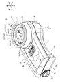
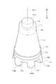
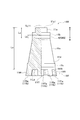
- FIG. 1 is an external perspective view of a handy non-destructive sugar meter 51 (sugar meter 51) which is an embodiment of a non-destructive measuring apparatus according to the present invention.
- FIG. 2 is a front view of the sugar content meter 51 of FIG.
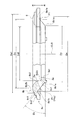
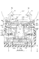
- FIG. 3 is a cross-sectional view at the position S3-S3 in FIG.
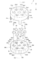
- FIG. 4 is an assembly diagram of the sugar content meter 51 of FIG.
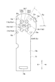
- FIG. 5 is a front view of the sensor substrate 13 provided in the saccharimeter 51 of FIG.
- FIG. 6 is a front view of the base substrate 14 provided in the saccharimeter 51 of FIG.
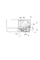
- FIG. 7 is a partial cross-sectional view for explaining an attachment state of the relay lens 18 provided in the saccharimeter 51 of FIG.
- FIG. 1 is an external perspective view of a handy non-destructive sugar meter 51 (sugar meter 51) which is an embodiment of a non-destructive measuring apparatus according to the present invention.
- FIG. 8 is a half sectional view of the ring lens 8 provided in the saccharimeter 51 of FIG.
- FIG. 9 is an assembly diagram for explaining the filter unit F provided in the saccharimeter 51 of FIG.
- FIG. 10 is a rear view of the filter unit F of FIG.
- FIG. 11 is a perspective view of the light guide member 11 provided in the saccharimeter 51 of FIG.
- FIGS. 12A and 12B are two views of the light guide member 11 of FIG. 11, (a) is a half sectional side view, and (b) is a rear view.
- FIG. 13 is an enlarged cross-sectional view of the SB portion in FIG.
- FIG. 14 is a diagram for explaining a control system of the saccharimeter 51 of FIG. FIG.
- FIG. 15 is a diagram for explaining a measurement mode by placing the saccharimeter 51 of FIG. 1 on the desktop.
- FIG. 16 is a diagram for explaining a measurement mode by gripping the saccharimeter 51 of FIG.
- FIG. 17 is a partial cross-sectional view for explaining an optical path in the saccharimeter 51 of FIG.
- FIG. 18 is a half sectional view for explaining a standard lid 52 used for calibration of the saccharimeter 51 of FIG.
- FIG. 19 is a partial cross-sectional view for explaining a diffusion plate 41 and its attachment mode as a modified example 1 of the saccharimeter 51 of FIG.
- FIG. 20 is a half cross-sectional view for explaining a light guide member 11W as a second modification of the sugar content meter 51 of FIG.
- a nondestructive measuring apparatus will be described by taking a handy nondestructive sugar content meter 51 (hereinafter also simply referred to as a sugar content meter 51) as an example.
- a sugar content meter 51 hereinafter also simply referred to as a sugar content meter 51
- an embodiment of a non-destructive measuring apparatus that uses fruits and vegetables as a measurement target will be described.
- the measurement target of the non-destructive measuring apparatus is not necessarily limited to fruits and vegetables.
- FIG. 1 is an external perspective view of the sugar content meter 51.
- FIG. 2 is a front view of the sugar content meter 51.
- FIG. 3 is a cross-sectional view at the position S3-S3 in FIG.
- FIG. 4 is an assembly diagram of the sugar content meter 51.
- each direction in the vertical and horizontal directions is defined as the direction shown in FIG.
- the sugar content meter 51 is a so-called handy type that can be held with one hand. Therefore, the up / down / left / right / front / rear directions shown in FIG. 1 are defined for convenience of explanation, and do not limit the posture of the saccharimeter 51 when used.
- the sugar content meter 51 has a substantially box-shaped box 1 whose front side is open, and a substantially lid-shaped lid 2 that is attached to the box 1 so as to close the front side.
- the box 1 has a base 1k formed in a substantially flat plate shape and a side wall 1h that rises forward from the periphery of the base 1k, and has a box shape.
- the box 1 and the lid 2 constitute a housing K that is integrated by interposing an O-ring 81 (see FIG. 3) between tapping screws (not shown).
- the saccharimeter 51 has a waterproof and dustproof function of IP65 or higher, which is a protective characteristic in the IEC (International Electrotechnical Commission) standard, due to the interposition of the O-ring 81 in the housing K and other seal structure (not shown).
- the housing K has a substantially cylindrical measuring part K1 formed in the upper part and centered on an axis CL1 extending in the front-rear direction, a substantially flat rectangular parallelepiped grip part K2 extending downward from the rear side of the measuring part K1,
- the lid body 2 includes a front surface portion 2a having a substantially flat front surface 2a1 in the grip portion K2, and a stage portion 2b protruding in a cylindrical shape forward from the front-rear direction position of the front surface portion 2a in the measurement unit K1.
- the lid body 2 has a bank portion 2c protruding forward at the left edge portion of the front surface portion 2a.
- the bank portion 2c is a portion that becomes a finger hook in a gripping state to be described later.
- An axis line CL1 of the measurement unit K1 coincides with a light receiving axis line CLT described later.
- the light receiving axis CLT is virtually set as an optical axis of light received by a photo sensor 13c described later.
- the display unit 3 that displays numbers, characters, and symbols in a visible manner on the front surface 2a1 of the lid 2 by a display element 14f (see FIGS. 3 and 6), and selection of an operation mode by pressing with a finger
- a switch portion 4 including a plurality of switch pressing portions 4a for performing zero reset is provided.
- the display unit 3 displays, for example, the operating state of the sugar content meter 51, the remaining battery level, and the sugar content (Brix value) obtained by the measurement under the control of the control unit CT (see FIGS. 3 and 14).
- a battery box 1b (see FIG. 3) that has a door 1b1 on the lower surface 1c and accommodates the battery is formed in the left rear portion inside the box body 1.
- a battery lid 5 is detachably attached to the doorway 1b1.
- an AAA dry battery is accommodated so that the user can insert and remove (hereinafter referred to as insertion / extraction) from the entrance 1b1.
- a push button 6 is provided on the upper right portion of the box 1. Each time the push button 6 is pressed by a user or the like, the switch 13d (see FIGS. 4 and 5) provided therein operates to alternately start and stop the measurement.
- the grip portion K2 is formed in a size that can be gripped by one adult hand.
- the grip portion K2 when gripping the grip portion K2 with the right hand, if the palm is applied to the rear surface 1a of the box 1, the four fingers from the index finger to the little finger are naturally attached to the bank portion 2c. The user can grip the sugar content meter 51 satisfactorily.
- the push button 6 is provided at a position where it can be easily pushed with the thumb.
- a concave curved contact portion 1a1 is formed on the right side of the rear surface 1a of the box 1 so that the thumb ball portion of the hand hits with good touch. .
- the box 1 and the lid 2 are made of resin.
- the resin is, for example, a near infrared absorption grade of black polycarbonate resin.
- An annular outer contact portion 7 is attached to the tip of the stage portion 2 b in the lid 2.
- the outer contact portion 7 is formed of a material having elasticity against at least backward compression.
- An example material is sponge.
- the inner portion surrounded by the outer contact portion 7 has a ring lens 8 that is a lens member, an inner contact portion 9, and a front surface 10 a of the stage base 10 in order from the outer side.
- a ring lens 8 that is a lens member, an inner contact portion 9, and a front surface 10 a of the stage base 10 in order from the outer side.
- Each part is visually recognized in an annular shape.
- the front end face 11a1 of the light guide member 11 is visually recognized at the center including the axis CL1.
- the inner contact portion 9 is formed in an annular shape and is attached to the front surface 10a.
- the inner contact portion 9 is formed of a material having elasticity against at least backward compression.
- An example material is sponge.
- the inner abutting portion 9 has a cut portion 9a that is wound in an arc shape radially outward in a part of the inner edge.
- the stage base 10 is attached so that the temperature sensing surface 12a of the temperature sensor 12 is exposed to the front surface. When viewed from the front, the temperature sensor 12 is arranged such that a part of the temperature sensing surface 12a enters the cut portion 9a.
- the temperature sensor 12 is a so-called thermopile, and measures the surface temperature T2 of the surface of the fruit and vegetables AS (see FIGS.
- the annular extending surfaces of the outer contact part 7 and the inner contact part 9 are surfaces (for example, substantially parallel) along the vertical direction that is the longitudinal direction of the grip part K2. In the posture, it is integrally formed on one end side (upper side) of the grip portion K2.
- the front end face 9b of the inner contact part 9 is on the rear side with respect to the front end face 7a of the outer contact part 7, as shown in FIG.
- the ring lens 8 is disposed at substantially the same front-rear position as the inner contact portion 9.
- the front end ridgeline portion 8 r located on the foremost side in the ring lens 8 is substantially at the same front-rear position as the front end surface 9 b of the inner contact portion 9.
- the front surface 10 a of the stage base 10 is on the rear side with respect to the front end surface 9 b of the inner contact portion 9.
- the front end surface 11a1 of the light guide member 11 is located at the same position in the front-rear direction or slightly on the rear side.
- FIGS. 3 and 4 two large substrates are accommodated in the housing K so as to face each other in the front-rear direction. Specifically, they are the sensor substrate 13 and the base substrate 14 from the base 1k side of the box 1.
- FIG. 5 is a front view for explaining the sensor substrate 13.
- the sensor substrate 13 is mounted with a receptacle 13b, a plurality of photosensors 13c, and a switch 13d on a front surface 13a that is a front side in a state where the sensor substrate 13 is housed in the housing K.
- the receptacle 13b is attached to the plug 14b of the base substrate 14 disposed in front of the sensor substrate 13, and the sensor substrate 13 and the base substrate 14 are electrically connected (see FIG. 3).
- the plurality of photosensors 13c is seven in this example. Six of the seven photosensors 13c are mounted around the light receiving axis CLT so that the angular pitch ⁇ p is equally spaced at 60 °, and the center positions of the photosensors 13c are on the line of the diameter ⁇ a. Has been. The remaining one is mounted at the center position of the diameter ⁇ a.
- the seven photosensors 13c are distinguished from each other as photosensors 13c1 to 13c7 as shown in FIG.
- the switch 13d repeats the ON operation and the OFF operation alternately every time the push button 6 is pushed in the assembled sugar content meter 51 as described above.
- the sensor substrate 13 has four through holes 13e at intervals of about 90 ° at positions radially outside the photosensor 13c.
- FIG. 6 is a front view for explaining the base substrate 14.
- the base substrate 14 has a circular hole 14g centered on the light receiving axis CLT at the top, a cut portion 14g1 formed in a rectangular shape downward at the lower edge of the hole 14g, and a slant 45 with respect to the top, bottom, left, and right outside the hole 14g. Each has a hole 14h in the direction.
- the base substrate 14 has an arcuate portion 14j having an arcuate outer shape centered on the light receiving axis CLT.
- a plurality of base elements 14 (n: n is an integer of 2 or more) as light emitting elements serving as display elements 14f, switches 14s, and light sources are provided on a front surface 14a that is a front side in a state of being accommodated in the housing K.
- a control unit CT that controls the operation of the LED 14d, the plurality of FB (feedback) photosensors 14e, and the sugar content meter 51 is mounted.
- a plug 14b connected to the receptacle 13b of the sensor substrate 13 is mounted on the rear surface 14c.
- the display element 14f is, for example, a display device such as a liquid crystal device or an organic EL (organic Electro-Luminescence) device.
- the 20 LEDs 14d are mounted in a radial posture at equal intervals with an angular pitch ⁇ pa of 18 ° on a line having a diameter ⁇ b around the hole 14g with the light receiving axis CLT as the center.
- the LEDs 14d are spaced apart in the circumferential direction at a position close to the arc portion 14j.
- the light source group in which the plurality of LEDs 14d are collected is also referred to as an LED group 14dG.
- the LEDs 14d are, for example, six types each having the next wavelength as a center wavelength, and are sequentially arranged in the circumferential direction. That is, the wavelengths are 880 nm, 900 nm, 950 nm, 980 nm, 1020 nm, and 1064 nm. In this case, in total, at least three LEDs 14d having each wavelength as the center wavelength are arranged. In particular, four LEDs 14d each having a center wavelength of 880 nm and 900 nm are arranged. Selection of LED14d with respect to six types of wavelengths is not limited to this.
- three types of short wavelengths and three types of long wavelengths so-called three wavelengths, in which three types of LEDs, each having three central wavelengths, are packaged together.
- a composite type LED may be used.
- a three-wavelength composite LED having three wavelengths of 880, 900, and 950 nm as a central wavelength and a three-wavelength composite LED having three wavelengths of 980, 1020, and 1064 nm as a central wavelength are used.
- a total of 20 of the former 8 and the latter 12 may be appropriately arranged.
- an FB photosensor 14e (feedback) photosensor 14e (hereinafter referred to as an FB photosensor 14e) is mounted in each of the vertical and horizontal directions.
- the four FB photosensors 14e are collectively referred to as an FB photosensor group 14eG.
- a flat cylindrical filter unit F is arranged on the sensor substrate 13 so as to cover the seven photosensors 13 c.
- a light guide member 11 that is solid and substantially in the shape of a truncated cone is disposed.
- the filter unit F and the light guide member 11 are addressed to the sensor substrate 13 from the front side, and between the sensor holder 13 and the unit holder 15 by the stage base 16 fastened and fixed by the tapping screw Na from the rear side. Is sandwiched between. Specific configurations of the light guide member 11, the stage base 16, and the filter unit F will be described later.
- the unit holder 15 has a round pan-like base portion 15 a that is open on the rear side and has a bottom on the front side, and a protruding portion 15 b that protrudes forward from the base portion 15 a.
- the base portion 15a has four through-holes 15a1 (see FIG. 4) extending in the front-rear direction for inserting the tapping screw Na in a 45 ° oblique direction with respect to the top, bottom, left, and right.
- the protruding portion 15 b is formed in a hollow conical shape in which the light guide member 11 is fitted inside with almost no gap, and protrudes forward through the hole 14 g of the base substrate 14.
- the outer peripheral surface of the projecting portion 15b is formed with a step portion 15b1 and a step portion 15b2 whose diameters are suddenly changed at two locations on the rear side and the tip side.
- the outer diameter of the protrusion 15b is set smaller than the inner diameter of the hole 14g of the base substrate 14, and the rear end 16a of the stage base 16 is engaged between the hole 14g and the protrusion 15b. .
- the rear end portion 16a is in contact with the step portion 15b1 of the protruding portion 15b, and the position in the front-rear direction is determined.
- the stage base 16 is formed in a substantially funnel shape in which the rear end side is narrowed.
- the rear end portion 16a is formed with a passage portion 16b that protrudes downward.
- the outer shape of the passage portion 16 b is adapted to engage with the cut portion 14 g 1 in the hole 14 g of the base substrate 14. That is, the position is determined around the light receiving axis CLT of the stage base 16 with respect to the base substrate 14.
- the inner peripheral surface of the rear end portion 16a is in contact with the outer surface of the protruding portion 15b of the unit holder 15 except for the passage portion 16b. That is, a gap Va (see FIG. 3) is formed between the passage portion 16b and the protruding portion 15b.
- the gap Va serves as a passage through which a lead wire from a temperature sensor substrate 17 described later passes in the front-rear direction.
- the rear end portion 16a is formed with four bosses 16a1 extending in the front-rear direction in an oblique 45 ° direction with respect to the top, bottom, left, and right in the front view.
- Each boss 16a1 is formed with a bottomed hole whose front is the bottom.
- the tapping screw Na shown in FIG. 3 is inserted into the through hole 13e of the sensor substrate 13 and the through hole 15a1 of the unit holder 15 and screwed into the bottomed hole formed in the boss 16a1 of the stage base 16.
- the unit holder 15 and the stage base 16 are fixed to the sensor substrate 13. At that time, the filter unit F and the light guide member 11 are sandwiched and held between the sensor substrate 13 and the unit holder 15.
- a stage base 10 is disposed in front of the stage base 16.
- the stage base 10 has a disk-shaped stage bottom 10b (see FIG. 3) and an annular peripheral wall 10c that rises rearward from the periphery of the stage bottom 10b.
- the aforementioned front surface 10a is the front surface of the stage bottom 10b.
- a through hole 10b1 is formed at the center of the stage bottom 10b (the position of the light receiving axis CLT).
- a through hole 10b2 is formed on the upper side with respect to the through hole 10b1.
- the front end portion of the light guide member 11 enters the through hole 10b1 from the rear side, and the front end surface 11a1 of the light guide member 11 is exposed forward.
- the temperature sensor 12 enters the through hole 10b2 from the rear side, and the temperature sensitive surface 12a of the temperature sensor 12 is exposed forward.
- a temperature sensor substrate 17 is disposed inside the stage base 10 surrounded by the peripheral wall portion 10c. As shown in FIG. 4, the temperature sensor substrate 17 has a disk shape and is formed with a center hole 17a and a pair of through holes 17b. Further, the temperature sensor 12 is mounted on the temperature sensor substrate 17. The temperature sensor substrate 17 is attached to the stage bottom 10b by a tapping screw (not shown) inserted through the through hole 17b.
- a lead wire (not shown) is drawn rearward from the temperature sensor board 17 and led to the sensor board 13 through the gap Va.
- the stage base 16 and the stage base 10 are made of resin.
- the resin is, for example, a near infrared absorption grade of black polycarbonate resin.
- the unit holder 15 is made of aluminum and has a black alumite treatment on the surface. By forming the unit holder 15 with metal, a shielding function is exhibited, and the influence of disturbance noise on the sensor substrate 13 can be reduced.
- FIG. 7 is an enlarged view of the SA portion in FIG.
- a stepped portion 10c2 having a slightly larger diameter on the front side is formed on the outer peripheral surface 10c1 of the peripheral wall portion 10c of the stage base 10 over the entire circumference.
- the relay lens 18 is attached to the step portion 10c2.
- the relay lens 18 is an annular optical member having an inner diameter Da, and has a circular shape with a diameter D in a cross-sectional shape orthogonal to the extending direction.
- the diameter ⁇ b7 of the center position Pc of the annular portion is set equal to the diameter ⁇ b of the center position of the LED 14d mounted on the base substrate 14 (see FIG. 6).
- the relay lens 18 is made of, for example, a transparent polycarbonate resin having light transmittance.
- the reduced diameter portion 10c4 is formed with a plurality of minute protrusions 10c5 that are spaced apart at a predetermined interval in the circumferential direction.
- the relay lens 18 is attached so as to be in close contact with the concave curved surface 10c3 toward the front side, and the minute protrusion 10c5 restricts the movement of the relay lens 18 to the rear side.
- the relay lens 18 When the relay lens 18 is attached to the stepped portion 10c2, the relay lens 18 is moved while elastically deforming the inner diameter from the rear side (see arrow DRa) so as to get over the microprojection 10c5 and to be recessed with the microprojection 10c5. Fit between the curved surface 10c3.
- FIG. 8 is a half cross-sectional view (partially cut off) for explaining the ring lens 8.
- the ring lens 8 includes an annular base portion 8a having a hole 8a1 and an annular shape, and a deflecting portion 8b extending from the annular base portion 8a so as to be inclined radially outward and forward. And a flange portion 8c projecting radially outward from the deflection portion 8b.
- the annular base portion 8a, the deflecting portion 8b, and the flange portion 8c are formed in an annular shape with an axis CL8 extending in the front-rear direction as a center.
- the deflecting unit 8b has a rear light incident surface 8b1 and a front light output surface 8b2.
- the light incident surface 8b1 is a conical circumferential surface that passes through a virtual reference circle P1 having a diameter Dc, and is inclined at an inclination angle ⁇ a so as to move forward as the distance from the axis CL8 increases.
- the light exit surface 8b2 has a cross-sectional arc shape having a radius Ra centered at the point P1a and a cross-sectional shape shown in FIG. 8 when the intersection of the plane including the axis CL8 and the virtual reference circle P1 is a point P1a. It is formed as a curved surface extending in the direction.
- the radial range in which the light incident surface 8b1 is formed is such that the inner diameter side edge 8b1a has a diameter Dd smaller than the diameter Dc, and the outer diameter side edge 8b1b has a diameter De larger than the diameter Dc.
- the radial range in which the light exit surface 8b2 is formed includes at least the radial range in which the light incident surface 8b1 is formed. Specifically, the inner diameter side edge 8b2a of the light exit surface 8b2 has a diameter Dd1 smaller than the diameter Dd, and the outer diameter side edge 8b2b has a diameter De1 larger than the diameter De.
- the flange portion 8c is connected to the edge portion 8b2b on the outer diameter side of the light exit surface 8b2 at the front portion, and the annular flat surface portion 8c1 orthogonal to the axis CL8 and the flat surface portion 8c1 on the radially outer side of the flat surface portion 8c1. And an annular shelf 8c2 that is formed in a step shape and is located on the rear side.
- the ring lens 8 is attached so as to block between the peripheral edge portion of the front surface 10 a of the stage base 10 and the inner surface 2 b 1 of the stage portion 2 b of the lid body 2.
- the hole 8a1 of the annular base portion 8a engages with a step portion formed on the periphery of the front surface 10a of the stage base 10, and is sealed with an O-ring (not shown) and fixed by an adhesive.
- the flat surface portion 8c1 of the flange portion 8c abuts on the rear surface of the inner flange 2b2 formed inwardly protruding at the tip of the stage portion 2b, and an O-ring 82 is interposed between the rear surface and the shelf portion 8c2.
- the filter unit F is sandwiched between a disk-shaped filter holder 20, a disk-shaped holder cover 21 that engages the filter holder 20 in the direction of the axis CLf of the filter holder 20, and the filter holder 20 and the holder cover 21.
- a plurality of (seven in this example) band-pass filters 31 to 37 which are optical band-pass filters.
- the seven band-pass filters 31 to 37 each have a rectangular outer shape having band-pass characteristics with different center wavelengths.
- the filter holder 20 and the holder cover 21 are made of resin.
- the resin is, for example, a near infrared absorption grade of black polycarbonate resin.
- m is an integer of 2 or more types of wavelengths are selected based on the absorption wavelength of the sugar.
- the photosensor 13c includes m photosensors 13c1 to 13c7. That is, the center wavelengths of the bandpass filters 31 to 37 are set to wavelengths ⁇ 1 to ⁇ 7 that are selected and set based on the conventionally known sugar absorption wavelength.
- the LED 14d is selected to have an emission center wavelength corresponding to each of the center wavelengths ⁇ 1 to ⁇ 7. Specifically, the LED 14d having an emission center wavelength that is equal to or close to each of the center wavelengths ⁇ 1 to ⁇ 7 is selected.
- the center wavelengths ⁇ 1 to ⁇ 7 selected and set in this example are as follows.
- the wavelength in parentheses is the emission center wavelength of the LED 14d that is selectively used corresponding to each of the bandpass filters 31-37.
- the center wavelengths of the bandpass filters 32 to 35, 37 other than the bandpass filters 31, 36 coincide with the emission center wavelength of the LED 14d used correspondingly.
- the difference between the center wavelength of the bandpass filters 31 and 36 and the emission center wavelength of the corresponding LED 14d is 5 nm and 14 nm, respectively.
- this degree of wavelength difference for example, 20 nm or less
- an LED with low power consumption and a broad emission spectrum is selected as the LED 14d, it is not necessary to select an LED having an emission center wavelength close to the center wavelength of the bandpass filter.
- FIG. 9 is a schematic assembly view of the filter unit F.
- the filter holder 20 is formed in a disk shape centered on the axis line CLf, and is formed on the front surface 20a with a circle having an angular pitch of 60 ° around the axis line CLf and a diameter ⁇ c centered on the axis line CLf as a central position.
- the six recessed portions 20b1 to 20b6 thus formed and the recessed portion 20b7 formed at the center are formed.
- the recesses 20b1 to 20b7 are rectangular recesses corresponding to the outer shape of the bandpass filter 22.
- the holder cover 21 has a base portion 21 a formed in a disk shape, and four claw portions 21 c that extend rearward from the peripheral edge portion of the base portion 21 a and engage with the filter holder 20.
- the claw portions 21c are spaced apart at an angular pitch of 90 ° in the circumferential direction.
- rectangular through holes 21b1 to 21b7 are formed at positions centered in a radial direction with a circle having an angular pitch of 60 ° centered on the axis line CLf and a diameter ⁇ d.
- a round through hole 21b7 is formed at the center position.
- the diameter ⁇ d is set equal to the diameter ⁇ c.
- the holder cover 21 is made closer to the filter holder 20 from the front side (see the arrow DRb), and the claw portion 21c is engaged with the engaged portion 20d provided on the filter holder 20 so as to be integrated with the filter holder 20.
- the bandpass filters 31 to 37 are accommodated in the recesses 20b1 to 20b7 of the filter holder 20, respectively, and the holder cover 21 is engaged with the filter holder 20 from the front side, thereby holding the bandpass filters 31 to 37.
- F is formed.
- FIG. 10 is a rear view of the filter unit F.
- FIG. 10 On the rear surface 20f of the filter holder 20, pocket portions 20e1 to 20e7 having rectangular openings turned forward are formed at positions corresponding to the recesses 20b1 to 20b7 formed on the front surface 20a.
- the recesses 20b1 to 20b7 and the pocket portions 20e1 to 20e7 are connected in the front-rear direction by rectangular through holes 20c1 to 20c7, respectively.
- the center positions in the radial direction of the through holes 20c1 to 20c6 are on a circle having a diameter ⁇ c.
- FIG. 11 is a perspective view of the light guide member 11 as viewed obliquely from the front.
- FIG. 12 is a half sectional view (a) and a rear view (b) of the light guide member 11.
- FIG. 12A is a half cross-section at the position S12-S12 in the rear view (b).
- the light guide member 11 is formed as a transparent member having optical transparency.
- the material is, for example, a transparent polycarbonate resin having optical transparency.
- the light guide member 11 is formed long in the front-rear direction.
- the light guide member 11 has a front end surface 11a1 as one longitudinal end surface, a cylindrical front protrusion 11a having a diameter Df centered on an axis CL11 extending in the front-rear direction, and a cylindrical shape having a diameter Dg larger than the diameter Df.
- the intermediate cylinder part 11b and the truncated cone part 11c which is connected to the rear side of the intermediate cylinder part 11b and gradually increases in diameter toward the rear are provided.
- the light guide member 11 includes a rear cylinder part 11e having a cylindrical shape with a diameter Dh and a rear cylinder part 11e through a step part 11d whose diameter is expanded in a direction perpendicular to the axis CL11 at the rear end part of the truncated cone part 11c. And a leg portion 11f having seven light guide protrusion portions 11f1 to 11f7 that are independently protruded rearward from the rear surface 11e1.
- the six light guide protrusions 11f1 to 11f6 are formed on a circle having an equiangular interval (angular pitch 60 °) about the axis CL11 and a diameter ⁇ e.
- the remaining one light guide projection 11f7 is formed in a cylindrical shape at the center position.
- the light guide protrusions 11f1 to 11f6 have engagement portions 11f1a to 11f6a that are reduced in shape at the stepped portions 11f1b to 11f6b and protrude further rearward at the rear tip portion.
- the light guide protrusion 11f7 has an engagement portion 11f7a that is reduced in diameter by the stepped portion 11f7b and further protrudes rearward at the rear tip portion. The positions of the stepped portions 11f1b to 11f7b of the engaging portions 11f1a to 11f7a and the front-rear direction positions of the front end surfaces are the same.
- the engaging portions 11f1a to 11f7a come into contact with the front surface of the base portion 21a of the holder cover 21 at the stepped portions, and respectively enter the through holes 21b1 to 21b7 of the holder cover 21 in the filter unit F from the front side. Yes.
- the assembly state of the filter unit F and the light guide member 11 with respect to the sensor substrate 13 will be described with reference to FIG. As described above, the assembly is performed by fixing the stage base 16 with the tapping screw Na so that the filter unit F and the light guide member 11 are sandwiched between the stage base 16 and the sensor substrate 13 in the front-rear direction. It is done.
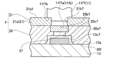
- FIG. 13 is a schematic cross-sectional view of the SB portion in FIG. That is, the assembled state of the photo sensor 13c7 of the sensor substrate 13, the filter unit F, and the light guide protrusion 11f7 of the light guide member 11 is shown. The same applies to the other photosensors 13c1 to 13c6, which will be described as representatives.
- the rear surface 20 f of the filter holder 20 is in contact with the front surface 13 a of the sensor substrate 13.
- the photosensor 13c7 mounted on the front surface 13a enters the pocket portion 20e7 formed in the filter holder 20 of the filter unit F.
- a band pass filter 37 is inserted into the recess 20 b 7 of the filter holder 20. The forward movement of the bandpass filter 37 is suppressed and restricted by a through hole 21b7 of the holder cover 21 formed smaller than the outer shape of the bandpass filter 37.
- the band pass filter 37 is located at the front facing position of the photo sensor 13c7.
- the engaging portion 11f7a of the light guide protrusion 11f7 of the light guide member 11 enters and engages with the through hole 21b7 of the holder cover 21 from the front side.
- the stepped portion 11 f 7 b of the light guide protrusion 11 f 7 is in contact with the front surface 21 a 1 of the base portion 21 a of the holder cover 21.
- FIG. 14 is a diagram for explaining a configuration of a control system in the sugar content meter 51.
- the control unit CT includes a central processing unit (CPU) CT1, a correction unit CT2, a light intensity processing unit CT3, a display control unit CT4, a light amount control unit CT5, and a storage unit CT6.
- the length L and width W (see FIG. 2) and the thickness H (see FIG. 3), which are the external dimensions of the saccharimeter 51, are generally set as follows, for example.
- L 113mm
- W 63mm
- H 43mm
- the outer diameter ⁇ f (see FIG. 3) of the measurement unit K1 is set to 48 mm, for example.
- the worker brings the measuring unit K1 of the sugar content meter 51 into contact with the fruits and vegetables AS to be measured.
- the operator uses the sugar content meter 51 so that the outer abutting portion 7 and the inner abutting portion 9 of the measuring unit K1 are the same. It can be placed on a table such as a desk 91 in the direction of the upper end, and the fruits and vegetables AS can be placed on the measuring unit K1 and measured.
- it is preferable to place a portion without a dent or a portion with a small dent on the measurement unit K1.
- the operator When measuring growing fruits and vegetables AS before harvesting or heavy or large fruits and vegetables AS, as shown in FIG. 16, the operator holds the grip portion K2 and places the measuring portion K1 on the surface of the fruits and vegetables AS. Measure in contact.
- the measurement part K1 is formed so as to protrude from the grip part K2.
- the convex portion of the uneven surface of the fruits and vegetables AS hits the grip portion K2, and the fruits and vegetables AS are placed unstable. Absent.
- the gripped fingers are less likely to hit the fruits and vegetables AS. Therefore, there is little possibility that a gap is generated between the outer contact part 7 and the inner contact part 9 and the fruits and vegetables AS and external light enters and the measurement accuracy is lowered.
- FIG. 17 is a schematic diagram for explaining an optical path when the sugar content is measured by the sugar content meter 51, and uses the measurement unit K1 in FIG. Moreover, in FIG. 17, the light guide member 11 shown by the cross section is not hatched so that drawing may not become complicated.
- the diameter ⁇ b (see also FIG. 6) in which the LEDs 14d are spaced apart in the circumferential direction, the diameter ⁇ b7 at the center of the relay lens 18 (see FIG. 7), and the diameter Dc of the virtual reference circle P1 of the ring lens 8 (see FIG. 8).
- the user places or measures the fruits and vegetables AS to be measured on the outer contact portion 7 and the inner contact portion 9 of the measurement unit K1 of the sugar meter 51 with the power of the sugar meter 51 turned on.
- the measuring part K1 of the saccharimeter 51 is pressed against the fruit and vegetables AS to be adhered.
- the fruits and vegetables AS are, for example, fruits and vegetables, such as tomatoes, apples, and watermelons.
- the outer contact portion 7 and the inner contact portion 9 are substantially in close contact with the surface of the fruit and vegetable AS by the weight of the fruits and vegetables AS or the pressing force of the user.
- the central processing unit CT1 grasps that the switch 13d is in the on state, it instructs the light amount control unit CT5 to cause the LED group 14dG to emit light.
- the light LT emitted upward from each LED 14 d of the LED group 14 dG passes through the relay lens 18 and reaches the ring lens 8.
- the space Vb that is the path of the light LT between the LED 14d and the ring lens 8 is closed on the radially outer side by the inner surface 2b1 of the stage portion 2b of the lid 2 and on the radially inner side the stage base 16 and the stage base. 10 outer peripheral surfaces 10c1. That is, the space Vb is a space that is closed on the radial side and is open only on the axial side.
- the tip portion on the axial direction side is closed by the ring lens 8.
- the main optical axis LTa of the light LT emitted from the LED 14d is indicated by a solid line.
- the main optical axis LTa passes through the center of the relay lens 18 and reaches the light incident surface 8b1 of the ring lens 8, the light incident surface 8b1 is inclined forward toward the radially outer side as shown in FIG.
- the light is emitted forward from the light output surface 8b2 at the light output angle ⁇ b corresponding to the inclination angle ⁇ a and the refractive index of the material of the ring lens 8.
- the exit angle ⁇ b is preferably set to satisfy 0 ⁇ b ⁇ 45 °.
- the angle ⁇ b is preferably set to be larger as the diameter Dc of the virtual reference circle P1 of the ring lens 8 is larger. Thereby, the light LTR (described later) that has entered the fruits and vegetables AS is easily collected in the center of the fruits and vegetables AS.
- the angle ⁇ b is preferably around 20 °.
- the light emitted forward from the light exit surface 8b2 becomes an annular light LTR including the main optical axis LTa and having a width in the inner and outer diameter directions. That is, in FIG. 17, the optical path LTb from the LED 14d of the light that is deflected and emitted from the ring lens 8 to the inner diameter side out of the annular light emitted from the light exit surface 8b2 is indicated by a broken line. An optical path LTc of the light deflected and emitted to the outermost diameter side from the LED 14d is indicated by a one-dot chain line.
- FIG. 17 shows the intensity characteristic Q of the annular light LTR at the front-rear direction position P2 after emission. From these, the radial intensity characteristic Q of the annular light LTR emitted from the ring lens 8 has a peak Qp that rises steeply on the main optical axis LTa, and rapidly decreases in intensity toward the inner diameter side and the outer diameter side. It is a characteristic.
- the intensity characteristics in the circumferential direction of the annular light LTR are substantially constant. That is, the intensity distribution in the circumferential direction of the annular light LTR is such that the plurality of LEDs 14d are spaced apart from each other in the circumferential direction, but the light emission characteristics that also spread in the circumferential direction of each LED 14d, the relay lens 18 and the ring lens 8 is averaged so as to be approximately the same when a plurality of LEDs 14d are simultaneously turned on.
- the annular light LTR emitted from the ring lens 8 is deflected at an angle ⁇ b in the direction in which the main optical axis LTa approaches the light receiving axis CLT as described above (the light receiving axis CLT is the same as the axis of the light guide member 11). Match). In other words, the annular light LTR emitted from the ring lens 8 proceeds so as to be reduced in diameter after being emitted from the ring lens 8.
- the front end surface 11a1 of the light guide member 11 is exposed at the central portion inside the inner contact portion 9.
- the light LTR emitted from the ring lens 8 is irradiated in a ring shape on the surface of the fruit and vegetables AS and enters the fruit and vegetables AS.
- the light LTR that has entered the fruit and vegetables AS is diffusely reflected inside and absorbed by the characteristics corresponding to the state of the fruit and vegetables AS, and part of the light LTR is emitted to the outside.
- a part of the light emitted to the outside enters the inside of the light guide member 11 from the front end surface 11a1 of the light guide member 11 exposed to the outside.
- the light that has entered the inside of the light guide member 11 is light that is emitted from the LED group 14dG, returns through the inside of the fruit and vegetables AS, and is hereinafter referred to as return light LTd.
- the return light LTd travels inside the light guide member 11 and is guided to the light guide protrusions 11f1 to 11f7 of the leg portion 11f.
- the return light LTd is light that enters the fruit and vegetables AS in a ring shape, is reflected inside, and is emitted to the outside from the central portion with respect to the ring-shaped entry portion that has entered. Therefore, even if the internal tissue of the fruits and vegetables AS is uneven in absorbance for each portion, it becomes the averaged light.
- the return light LTd is obtained with high efficiency with respect to the light output from the LED 14d, and even if there is a deviation in the absorbance of the internal tissue of the fruit and vegetable AS, the absorbance of the fruit and vegetable AS is less affected by the deviation. It is obtained as light reflected with higher accuracy.
- the return light LTd guided to the light guide protrusions 11f1 to 11f7 of the leg portion 11f is a homogeneous light with no bias in characteristics, and from the respective rear end surfaces 11fb of the engaging portions 11f1a to 11f7a. Light is emitted toward the band-pass filters 31 to 37 as protruding portion emitted light LTe (LTe1 to LTe7).
- the rear end surface 11fb is the other end surface of the light guide member 11 with respect to the front end surface 11a1 that is one longitudinal end surface.
- the protruding portion emitted light LTe emitted from the engaging portions 11f1a to 11f7a is split by the bandpass filters 31 to 37 according to the respective spectral characteristics and is incident on the photosensors 13c1 to 13c7.
- the photosensors 13c1 to 13c7 detect the intensities Q1 to Q7, which are the received light intensity, and send them to the light intensity processing unit CT3 (see FIG. 14). That is, the intensities Q1 to Q7 obtained from the photosensors 13c1 to 13c7 are the spectral intensities of the center wavelengths ⁇ 1 to ⁇ 7 of the bandpass filters 31 to 37, respectively.
- the light intensity processing unit CT3 obtains the absorbances of the wavelengths ⁇ 1 to ⁇ 7 from the intensities Q1 to Q7 by a known calculation method, and calculates the Brix value Y from each absorbance.
- a specific calculation method example is as follows.
- the absorbance A at the wavelength ⁇ is expressed by Equation (1).
- I0 ( ⁇ ) is the intensity of light having a wavelength ⁇ entering the measurement object serving as a reference
- IS ( ⁇ ) is the intensity of light having the wavelength ⁇ emitted from the measurement object.
- the reference wavelength is the wavelength ⁇ 6
- the absorbance differences A1 to A5 and A7 are expressed by the following equations (2-1) for the other six wavelengths ⁇ 1 to ⁇ 5 and ⁇ 7, respectively. Obtained by (2-6).
- the Brix value Y is calculated by the following equation (3). ... (3)
- PL0 to PL8 are coefficients obtained by multiple regression analysis using absorbance data of a plurality of measurement objects (fruits and vegetables AS) in advance.
- the temperature T1 is the surface temperature of the measurement target (fruits and vegetables AS) measured by the temperature sensor 12, and the temperature T2 is a temperature corresponding to the housing K measured by the temperature sensor 12.
- the control unit CT includes a correction unit CT2.
- the correction unit CT2 closes the light amount of the LED group 14dG based on the light amount information JL from the FB photosensor group 14eG and the temperature information JT from the temperature sensor 12.
- the saccharimeter 51 includes an FB photosensor group 14eG, a temperature sensor 12, and a correction unit CT2, and can stabilize the amount of light emitted from the plurality of LEDs 14d and suppress time fluctuation. Thereby, the measurement accuracy of the sugar content meter 51 is further improved.
- Control part CT is not restricted to what controls all LED14d of LED group 14dG to light-emit simultaneously.
- the control unit CT may cause the corresponding LEDs 14d to emit light sequentially in time series for each of the set six types of wavelengths or in the circumferential arrangement order, and measure the received light intensity with the photosensors 13c1 to 13c7 each time.
- the LED group 14dG is caused to emit light simultaneously, power consumption increases even in a short time. Therefore, when the load of the power source needs to be reduced, the latter method in which the plurality of LEDs 14d are sequentially lit in time series is preferable.
- the sugar meter 51 which is a non-destructive measuring device for fruits and vegetables described above, uses a plurality of LEDs 14d as a light source for light irradiating the fruits and vegetables AS. Thereby, the sugar content meter 51 is small in power consumption and installation space of the light source, and can be downsized so that the housing K can be gripped with one hand. Therefore, it is possible to easily measure the growing fruits and vegetables before harvesting.
- a plurality of LEDs 14d are arranged side by side in the circumferential direction, and light emitted from each LED 14d is irradiated toward the fruits and vegetables AS through the annular ring lens 8. Therefore, light is incident on the fruits and vegetables AS as an annular light beam. Thereby, even if there is a bias in the light absorption of the tissue inside the fruits and vegetables AS, it is difficult to be affected by the bias, averaged light emission is obtained, and a measurement result that well reflects the state of the fruits and vegetables AS is obtained.
- the ring lens 8 has an optical characteristic that the light incident from the LED 14d is deflected toward the center of the ring lens 8 to be emitted. Therefore, the intensity of the return light reflected inside the fruits and vegetables AS and emitted toward the central portion of the ring lens 8 is high, and the use efficiency of the light emission of the LED 14d is high.
- the sugar content meter 51 can reduce power consumption by suppressing the light emission intensity of fruits and vegetables with high light transmittance, and is suitable for a hand-held type driven by a battery. In addition, it is easy to obtain sufficient return light for measurement even for fruits and vegetables with low light transmittance due to thick skin, etc., and the sugar content meter 51 has many types of fruits and vegetables that can be measured, and is excellent in versatility.
- the sugar content meter 51 has an annular relay lens 18 that condenses the light from the LED 14 d onto the ring lens 8 in the middle of the light output path from the LED 14 d to the ring lens 8.
- the relay lens 18 By arranging the relay lens 18, the light emitted from the LED 14 d can be introduced into the ring lens 8 with higher efficiency and irradiated onto the fruits and vegetables AS.
- the sugar content meter 51 can reduce power consumption and is suitable for a handy type. Moreover, it is easier to obtain return light sufficient for measurement even for fruits and vegetables with low light transmittance due to thick skin, etc., and the sugar content meter 51 has many types of fruits and vegetables that can be measured, and is excellent in versatility.
- the relay lens 18 since the relay lens 18 is disposed, the light path distance between the LED 14d and the ring lens 8 can be increased. Therefore, the ring lens 8 can be disposed at a position closer to the fruits and vegetables AS. Thereby, the light flux emitted from the ring lens 8 is incident on the fruits and vegetables AS in a sufficiently narrow ring shape, and the incident light intensity per unit area can be further increased. Accordingly, the light use efficiency of the LED 14d is further improved. Moreover, it is possible to suppress the influence of the incident light from the outside to a level that can be substantially ignored. Thereby, the saccharimeter 51 can perform a highly accurate measurement.
- the relay lens 18 can be arranged to increase the light path distance between the LED 14d and the ring lens 8, the stage portion on which the fruits and vegetables AS are placed is sufficiently protruded with respect to the grip portion gripped by the hand. It becomes possible. As a result, as shown in FIG. 16, even when gripping the grip part K2 and measuring the fruit and vegetables AS, the fruit and vegetables AS and the finger gripping the grip part K2 do not touch each other, and the work is easy to touch and easy. In addition, it can be performed with high efficiency. Further, if a slight shift occurs in the mounting position of the LED 14d on the base substrate 14 due to manufacturing variations, a slight difference also occurs in the light output angle of each LED 14d.
- the relay lens 18 is disposed as a reduction optical system lens between the LED 14d and the ring lens 8. That is, the relay lens 18 creates a light source reduction system from the light emitted from the annular light source (the plurality of LEDs 14 d arranged in an annular shape) and inputs the light source reduction system to the ring lens 8.
- the ring lens 8 irradiates the fruits and vegetables with a reduction system of the input light source as an annular beam.
- the saccharimeter 51 can perform a highly accurate measurement.
- the sugar content meter 51 has an inner contact portion 9 and an outer contact portion 7 at inner and outer positions in the radial direction with respect to the ring lens 8.
- the fruits and vegetables AS are closed by the ring lens 8, the fruits and vegetables AS, the inner contact portion 9, and the outer contact portion 7 in a state where the fruits and vegetables AS are addressed to the measurement portion K ⁇ b> 1.
- a space Vc is formed.
- the space between the stage portion 2 b and the fruits and vegetables AS is closed by the outer contact portion 7.
- the space between the stage portion 2 b and the fruits and vegetables AS is closed by the inner contact portion 9.
- the saccharimeter 51 includes a light guide member 11 having a longitudinal direction in the light receiving axis CLT direction.
- One end side of the light guide member 11 is defined as a front end surface 11a1 of a light incident surface of the return light LTd, and the other end side thereof.
- the light exit surface of the return light LTd toward the photosensor 13c is used.
- the return light LTd that has entered from the light incident surface is guided to the light exit surface with internal reflection of the light guide member 11 over a relatively long distance, so that the light that has reached the light exit surface has reached the light exit surface. Homogeneous light regardless of location. Accordingly, the sugar content meter 51 has no bias in the characteristics of light entering each of the photosensors 13c1 to 13c7, and can perform measurement with high accuracy.
- the photosensors 13c1 to 13c7 are located on the rear side, that is, the outer contact portion 7 and the inner contact portion, rather than the LED group 14dG serving as the light source in the positional relationship in the front-rear direction in the housing K. It is arranged at a position far from 9. Accordingly, the sensor substrate 13 on which the photosensors 13c1 to 13c7 are mounted is disposed in the vicinity of the rear surface 1a of the box 1, and the light guide member 11 is disposed through the hole 14g of the base substrate 14.
- the sugar content meter 51 is provided with a standard lid 52 for calibration.
- FIG. 18 is a half cross-sectional view for explaining the usage state of the standard lid 52, and shows the standard lid 52 and a part of the measurement unit K 1 in the housing K.
- the standard lid 52 has a cylindrical shape that covers the opening at the tip of the measurement unit K1, and is used by being placed on the stage 2b of the lid 2.
- the standard lid 52 includes a round pan-shaped base body 52a and a reflector 52b attached to the inside of the base body.
- the reflector 52b has a concave portion 52b1 that is recessed in a circular shape toward the front at the center portion, and an annular curved surface that is inclined forward toward the outer side in the radial direction and has a convex rear side.
- the recess 52b1 faces the front end face 11a1 of the light guide member 11 in the front-rear direction, and the curved surface part 52b2 faces at least the light exit direction (in the direction of the main optical axis LTa shown in FIG. 17).
- the reflector 52b is solidly formed of a white member.
- the white member is, for example, a fluororesin.
- the reflector 52b functions as a standard substitute for the fruits and vegetables to be measured. That is, the annular light LTR (see FIG. 17) emitted from the ring lens 8 is irradiated onto the curved surface portion 52b2 of the reflector 52b, and a part thereof enters the inside. A part of the light that has entered the reflector 52b exits from the recess 52b1 while diffusing inside, and enters the light guide member 11 as return light LTd.
- the light intensity processing unit CT3 and the central processing unit CT1 are calibrated so that the measurement result based on the return light LTd becomes a quasi-measurement value using the standard lid 52 that is preset and stored in the storage unit CT6. I do.
- Measurement with the standard lid 52 is easy because the standard lid 52 is small and easy to carry, and can simply be put on the stage 2b. Therefore, the calibration work is easy, and the correlation between an individual with the saccharimeter 51 and another individual can be easily ensured.
- the embodiment of the present invention is not limited to the configuration and procedure described above, and may be modified without departing from the gist of the present invention.
- the sugar content meter 51 of the embodiment has a diffusion unit WB for diffusing the passing light on the path of the returning light until the returning light emitted through the fruits and vegetables AS passes through the light guide member 11 and exits from the rear end face 11fb.
- the structure may be modified so as to positively diffuse the return light. That is, the diffusing portion WB is provided between the portion of the surface of the fruit and vegetables AS brought into contact with the inner contact portion 9 and surrounded by the annular inner contact portion 9 and the rear end surface 11fb of the light guide member 11. May be. This will be described next as modified examples 1 to 3.
- FIG. 19 is a partial cross-sectional view for explaining the first modification, and corresponds to the light guide member 11 in FIG. 17 and the vicinity thereof.
- the diffusion plate 41 is disposed in front of the front end surface 11a1 of the light guide member 11 in the sugar content meter 51 of the embodiment.
- the diffusion plate 41 is attached to the stage base 10 with, for example, an adhesive or a double-sided tape so as to cover the entire front end surface 11a1 when viewed from the front.
- the diffusion plate 41 diffuses the light incident on the front surface 41a and emits it from the rear surface 41b.
- the kind of diffusion plate 41 is not limited.
- a well-known diffusion plate such as a diffusion plate formed by dispersing and mixing a diffusing agent in a transparent resin, or a diffusion plate in which a minute lens is formed on at least one surface of a transparent resin plate can be applied.
- the return light LTd is diffused and incident from the front end surface 11 a 1 into the light guide member 11 by the diffusion plate 41 arranged in front of the front end surface 11 a 1 of the light guide member 11. .
- the return light LTd that passes through the fruits and vegetables AS and enters the light guide member 11 is positively diffused by the diffusion plate 41, is more highly homogenized, and enters the light guide member 11.
- the homogenized return light LTd passes through the light guide member 11, passes through the bandpass filters 31 to 37, and enters the photosensors 13c1 to 13c7. Therefore, the correlation coefficient between the absorbance and the Brix value Y is increased, and the measurement accuracy is improved, for example, variation in absorbance and Brix value Y when the same fruit and vegetable AS is repeatedly measured is reduced.
- FIG. 20 is a half sectional view of the light guide member 11W.
- the light guide member 11 ⁇ / b> W is obtained by forming a part of the light guide member 11 in the direction of the axis CL ⁇ b> 11 as a diffusion member 42.
- the light guide member 11W includes a diffusion portion WB between the front end surface 11a1 and the rear surface 11e1 (see FIG. 12) of the rear cylinder portion 11e.
- the light guide member 11W includes a diffusing member 42 having a thickness Lb as a diffusing portion WB with a position at a distance La from the front end surface 11a1 to the rear side as a rear end.
- the diffusing member 42 is formed, for example, by dispersing and blending a diffusing agent in a transparent resin.
- the return light LTd (not shown in FIG. 20) incident on the light guide member 11W from the front end surface 11a1 enters from the front end of the diffusion member 42 and diffuses and exits to the rear side.
- the maximum value of the distance La can be a distance Lc from the front end surface 11a1 to the rear surface 11e1 of the rear cylinder portion 11e. That is, the distance La can be set in the range from the thickness Lb to the distance Lc. Further, the thickness of the diffusing member 42 can be set up to a distance La at maximum.
- the return light LTd that has passed through the fruits and vegetables AS and entered the light guide member 11W is positively diffused and more highly homogenized when passing through the diffusion member 42 provided in the light guide member 11W.
- the homogenized return light LTd exits the light guide member 11W, passes through the bandpass filters 31 to 37, and enters the photosensors 13c1 to 13c7. Therefore, the correlation coefficient between the absorbance and the Brix value Y is increased, and the measurement accuracy is improved, for example, variation in absorbance and Brix value Y when the same fruit and vegetable AS is repeatedly measured is reduced.
- a light guide member 11WA formed of a resin in which a diffusing agent is dispersed in the same shape may be applied (reference numerals are shown in the figure). 12).
- the return light LTd incident on the light guide member 11WA is actively diffused as it travels through the light guide member 11, and is homogenized to a higher degree. Thereafter, the homogenized return light LTd exits from the light guide member 11WA, passes through the bandpass filters 31 to 37, and enters the photosensors 13c1 to 13c7. Therefore, the correlation coefficient between the absorbance and the Brix value Y is increased, and the measurement accuracy is improved, for example, variation in absorbance and Brix value Y when the same fruit and vegetable AS is repeatedly measured is reduced.
- Modifications 1 to 3 can be freely combined within a combinable range.
- the relay lens 18 and the ring lens 8 may be an integrated optical member.
- the relay lens 18 or the ring lens 8 may be a plurality of optical members.
- the light from the LED 14d is annularly emitted from the tip of the measurement unit K1, and the emission direction is configured by one optical member or a plurality of optical members that deflects the emission direction toward the light receiving axis CLT with an angle ⁇ b.
- An optical system may be used.
- the light source group 14dG has been described using six types of LEDs 14d having six types of light emission center wavelengths among the seven types of center wavelengths ⁇ 1 to ⁇ 7.
- the present invention is not limited to this, and the light intensity required for the measurement of light having a plurality of center wavelengths selected and set as a bandpass filter based on the emission spectrum of the LED 14d having one emission center wavelength or having a broad emission spectrum. If it is determined that the LED 14d is obtained, the LED 14d may be shared for a plurality of center wavelengths.
- q kinds of LEDs each having q (1 ⁇ q ⁇ m) types of emission center wavelengths with respect to m (integers of 2 or more) types of wavelengths ( ⁇ 1 to ⁇ m) selected and set as the center wavelength of the bandpass filter. May be used.
- at least m photosensors 13c are provided.
- the light source is not limited to the LED, and may be another light emitting element.
Landscapes
- Physics & Mathematics (AREA)
- Chemical & Material Sciences (AREA)
- Health & Medical Sciences (AREA)
- Life Sciences & Earth Sciences (AREA)
- General Physics & Mathematics (AREA)
- Analytical Chemistry (AREA)
- Biochemistry (AREA)
- General Health & Medical Sciences (AREA)
- Immunology (AREA)
- Pathology (AREA)
- Spectroscopy & Molecular Physics (AREA)
- Engineering & Computer Science (AREA)
- Food Science & Technology (AREA)
- Medicinal Chemistry (AREA)
- Investigating Or Analysing Materials By Optical Means (AREA)
- Analysing Materials By The Use Of Radiation (AREA)
Abstract
Description
例として、青果物に照射入光させた近赤外光の透過光を利用して吸光度を測定し、測定した吸光度に基づいて青果物の糖度をBrix値として得る非破壊測定装置がある。
この非破壊測定装置は、特許文献1に、非破壊糖度測定装置として記載されている。 2. Description of the Related Art Non-destructive measuring devices for fruits and vegetables that measure the absorbance of fruits and vegetables non-destructively are known.
As an example, there is a nondestructive measuring apparatus that measures the absorbance using transmitted light of near-infrared light irradiated and incident on fruits and vegetables and obtains the sugar content of fruits and vegetables as a Brix value based on the measured absorbance.
This nondestructive measuring device is described in
具体的には、生育中の青果物に対しても容易に使用できるように、片手で把持できる程度に小型化された非破壊測定装置が望まれている。 From the producers of fruits and vegetables, not only the harvested fruits and vegetables but also the fruits and vegetables that are in the pre-harvest (growth) state, etc., the absorbance is measured non-destructively to determine the harvest time. Therefore, an apparatus that can grasp the sugar content is desired.
Specifically, a non-destructive measuring device that is small enough to be grasped with one hand is desired so that it can be easily used for growing fruits and vegetables.
LEDを採用した場合、皮の厚い青果物でも光量不足とならず安定的に測定できる工夫も新たに必要になる。 When the nondestructive measuring apparatus is miniaturized to the extent that it can be grasped with one hand, the use of a light emitting diode (LED) as the light source is considered from the viewpoint of space saving and power saving.
In the case of adopting the LED, it is necessary to devise a device that can measure stably without causing a light quantity shortage even for fruits and vegetables with thick skin.
前記筐体の内部において周方向に離隔配置された複数の光源からなる光源群と、
前記当接部に囲まれた内側部分に前記当接部よりも小さい環状に配置され、前記光源群から出た光を、前記筐体の外部に環状に出射するリングレンズと、
前記リングレンズの内側に一端面が露出し、他端面が前記筐体の内部に位置して前記一端面から入射した光を前記他端面から外部に出射する導光部材と、
前記筐体内に配置され、前記導光部材の前記他端面から出射した光を受光するフォトセンサと、
前記フォトセンサの受光強度に基づいて吸光度を求める光強度処理部と、
からなる非破壊測定装置が提供される。
好ましくは、前記非破壊測定装置は、前記光源群と前記リングレンズとの間において、前記光源群からの光を前記リングレンズに誘導する環状の中継レンズから更になる。
好ましくは、前記非破壊測定装置において、前記リングレンズから出射した環状の光の主光軸は、前記リングレンズから出射した後に縮径する方向に傾斜している。
好ましくは、前記非破壊測定装置において、前記フォトセンサは、少なくともm個(mは2以上の整数)のフォトセンサを含み、
前記非破壊測定装置は、前記m個のフォトセンサのそれぞれと前記導光部材の前記他端面との間において、異なるm種類の波長λ1~λmのそれぞれを中心波長として有するバンドパスフィルタから更になる。
好ましくは、前記非破壊測定装置において、前記光強度処理部は、前記吸光度を、前記m個のフォトセンサによって得られた前記波長λ1~λmのそれぞれに対応した受光強度に基づいて求めると共に、求めた前記吸光度からBrix値を算出する。
好ましくは、前記非破壊測定装置において、前記グリップ部は、長手を有して把持可能に形成され、
前記測定部は、前記グリップ部における前記長手の一方の端部に、前記当接部の延在方向を前記長手に沿う方向として形成されると共に、前記当接部の先端面が、前記グリップ部の表面よりも突出した位置にある。
好ましくは、前記非破壊測定装置は、前記測定対象を前記当接部に当接させた状態で、前記測定対象における前記当接部に囲まれた表面と前記導光部材の前記他端面との間において、通過する光を拡散させる拡散部から更になる。 According to one aspect of the present invention, a housing including a grip portion that can be gripped, and a measurement portion having an annular contact portion for making contact with a measurement object,
A light source group consisting of a plurality of light sources spaced apart in the circumferential direction inside the housing;
A ring lens that is arranged in an annular shape smaller than the contact portion on the inner part surrounded by the contact portion, and emits light emitted from the light source group in an annular shape to the outside of the housing;
One end surface is exposed inside the ring lens, the other end surface is located inside the housing, and a light guide member that emits light incident from the one end surface to the outside from the other end surface;
A photosensor disposed in the housing and receiving light emitted from the other end surface of the light guide member;
A light intensity processing unit for obtaining an absorbance based on the received light intensity of the photosensor;
A nondestructive measuring device is provided.
Preferably, the nondestructive measuring device further includes an annular relay lens that guides light from the light source group to the ring lens between the light source group and the ring lens.
Preferably, in the nondestructive measuring apparatus, the main optical axis of the annular light emitted from the ring lens is inclined in a direction of reducing the diameter after being emitted from the ring lens.
Preferably, in the nondestructive measurement apparatus, the photosensor includes at least m (m is an integer of 2 or more) photosensors,
The nondestructive measuring device further includes a band pass filter having m different wavelengths λ1 to λm as center wavelengths between each of the m photosensors and the other end surface of the light guide member. .
Preferably, in the nondestructive measurement apparatus, the light intensity processing unit obtains the absorbance based on the received light intensity corresponding to each of the wavelengths λ1 to λm obtained by the m photosensors. The Brix value is calculated from the absorbance.
Preferably, in the nondestructive measuring device, the grip portion has a longitudinal shape and is formed so as to be grippable,
The measuring part is formed at one end of the longitudinal part of the grip part with the extending direction of the abutting part as a direction along the longitudinal direction, and the tip surface of the abutting part is formed by the grip part. It is in a position protruding from the surface of.
Preferably, the non-destructive measuring apparatus is configured such that the surface surrounded by the contact portion of the measurement target and the other end surface of the light guide member in a state where the measurement target is in contact with the contact portion. It further comprises a diffusion part for diffusing light passing therethrough.
図1は、糖度計51の外観斜視図である。図2は、糖度計51の前面図である。図3は、図2におけるS3-S3位置での断面図である。図4は、糖度計51の組立図である。 First, the configuration of the
FIG. 1 is an external perspective view of the
糖度計51は、片手で把持可能な、いわゆるハンディタイプである。従って、図1に示した上下左右前後の方向は、説明の便宜上規定するものであって、糖度計51の使用時の姿勢などを限定するものではない。 In the following description, each direction in the vertical and horizontal directions is defined as the direction shown in FIG.
The
糖度計51は、前方側が開放した略箱状の箱体1と、箱体1に対し、前方側を塞ぐように取りつけられる略蓋状の蓋体2と、を有する。
箱体1は、図3に示されるように、概ね平板状に形成された基部1kと、基部1kの周囲から前方に立ち上がる側壁部1hと、を有し、箱状とされている。 First, the external configuration of the
The
As shown in FIG. 3, the
糖度計51は、筐体KにおけるOリング81の介在や他の図示しないシール構造などにより、IEC(International Electrotechnical Commission)規格における保護特性であるIP65以上の防水防塵機能を有する。 The
The
蓋体2は、前面部2aの左縁部において前方に突出した土手部2cを有する。土手部2cは、後述する把持状態における指掛かりとなる部分である。 The
The
受光軸線CLTは、後述するフォトセンサ13cで受光する光の光軸として仮想設定される。 An axis line CL1 of the measurement unit K1 coincides with a light receiving axis line CLT described later.
The light receiving axis CLT is virtually set as an optical axis of light received by a
出入口1b1には、電池蓋5が着脱自在に取りつけられている。
電池ボックス1bには、糖度計51の電源として、例えば単4形の乾電池が、使用者により出入口1b1から挿入及び抜去(以下挿抜)可能に収容される。 A
A
In the
この糖度計51を使用するために、例えば右手でグリップ部K2を把持する際に、箱体1の後面1aに手のひらを当てると、人差し指から小指までの4本の指が自然と土手部2cに掛かり、使用者は、糖度計51を良好に把持できる。
この把持状態で、押し釦6は、親指で押し易い位置に設けられている。
また、箱体1の後面1aの右部には、手の母指球の部分が感触よく当たるように、母指球に合わせた凹曲面の当て部1a1(図1参照)が形成されている。 The grip portion K2 is formed in a size that can be gripped by one adult hand.
In order to use the
In this gripping state, the
In addition, a concave curved contact portion 1a1 (see FIG. 1) is formed on the right side of the
内当接部9は、少なくとも後方への圧縮に対し弾性を有する材料で形成されている。材料例は、スポンジである。
内当接部9は、内縁の一部において、径方向の外方に円弧状に抉られた切り込み部9aを有する。
ステージベース10には、温度センサ12の感温面12aが前面に露出するように取りつけられている。
温度センサ12は、前方から見たときに、感温面12aの一部が切り込み部9a内に進入して配置されている。
温度センサ12は、いわゆるサーモパイルであって、測定部K1に宛がわれた測定対象である青果物AS(図15及び図16参照)の表面の温度T2を非接触で測定すると共に、周囲の筐体Kに相当する温度T1も測定する。温度センサ12は、測定した温度T1及び温度T2を、温度情報JTとして制御部CTに向け出力する(図14参照)。温度T1と温度T2とは逆でもよい。すなわち、青果物ASの表面の温度を、温度T1としてもよい。
筐体Kにおいて、測定部K1は、外当接部7及び内当接部9の環状形状の延在面が、グリップ部K2の長手方向である上下方向に沿う面(例えば概ね平行)となる姿勢で、グリップ部K2の一端側(上方側)に一体形成されている。 The
The
The inner
The
When viewed from the front, the
The
In the housing K, in the measurement part K1, the annular extending surfaces of the
リングレンズ8は、内当接部9と概ね同じ前後位置に配置されている。
リングレンズ8における最も前側に位置する前端稜線部8rは、内当接部9の前端面9bと概ね同じ前後位置にある。
内当接部9の前端面9bに対し、ステージベース10の前面10aは後方側にある。
ステージベース10の前面10aに対し、導光部材11の前端面11a1は前後方向に同じ位置か、又はわずかに後方側に位置している。 As for the position in the front-rear direction of each part in the measurement part K1, the
The
The front
The
With respect to the
図3及び図4に示されるように、筐体Kの内部には、2枚の大きな基板が、前後方向に対向して並設収容されている。具体的には、箱体1の基部1k側からセンサ基板13及びベース基板14である。 Next, components and the like arranged inside the housing K will be described with reference to FIGS.
As shown in FIGS. 3 and 4, two large substrates are accommodated in the housing K so as to face each other in the front-rear direction. Specifically, they are the
センサ基板13は、筐体K内に収納された状態での前側となる前面13aに、レセプタクル13bと複数のフォトセンサ13cとスイッチ13dとが実装されている。 FIG. 5 is a front view for explaining the
The
残りの1個は、径φaの中心位置に実装されている。
7個のフォトセンサ13cは、後の説明で区別が必要となる場合、図5に示されるように、フォトセンサ13c1~13c7として区別する。 The plurality of
The remaining one is mounted at the center position of the diameter φa.
The seven
ベース基板14は、上部に受光軸線CLTを中心とする円形の孔14gと、孔14gの下縁において、下方に向け矩形に抉られた切り込み部14g1と、孔14gの外側における上下左右に対する斜め45°方向にそれぞれ孔14hを有する。
ベース基板14は、受光軸線CLTを中心とする円弧状の外形とされた円弧部14jを有する。 FIG. 6 is a front view for explaining the
The
The
一方、後面14cには、センサ基板13のレセプタクル13bと接続するプラグ14bが実装されている。 A plurality of base elements 14 (n: n is an integer of 2 or more) as light emitting elements serving as
On the other hand, a
詳しくは、LED14dは、円弧部14jに近い位置において周方向に離隔配置されている。
複数のLED14dをまとめた光源群として、以下、LED群14dGとも称する。 The plurality of
Specifically, the
Hereinafter, the light source group in which the plurality of
すなわち、その波長は、880nm,900nm,950nm,980nm,1020nm,及び1064nmである。
この場合、20個全体で、各波長を中心波長とするLED14dは少なくとも3個配置される。中でも、880nm及び900nmをそれぞれ中心波長とするLED14dは、それぞれ4個配置される。
6種類の波長に対するLED14dの選択は、これに限定されない。別の例として、6種類の波長の内、短い波長の3種と長い波長の3種とについて、3種の波長それぞれを中心波長とする3種のLEDを一つにパッケージした、いわゆる3波長複合型のLEDを用いてもよい。
例えば、880,900,950nmの3種の波長を中心波長とする3波長複合型LEDと、980,1020,1064nmの3種の波長を中心波長とする3波長複合型LEDと、を、用い、例えば、前者の8個及び後者の12個の合計20個を適宜配置してもよい。 The
That is, the wavelengths are 880 nm, 900 nm, 950 nm, 980 nm, 1020 nm, and 1064 nm.
In this case, in total, at least three
Selection of LED14d with respect to six types of wavelengths is not limited to this. As another example, among the six wavelengths, three types of short wavelengths and three types of long wavelengths, so-called three wavelengths, in which three types of LEDs, each having three central wavelengths, are packaged together. A composite type LED may be used.
For example, a three-wavelength composite LED having three wavelengths of 880, 900, and 950 nm as a central wavelength and a three-wavelength composite LED having three wavelengths of 980, 1020, and 1064 nm as a central wavelength are used. For example, a total of 20 of the former 8 and the latter 12 may be appropriately arranged.
フィルタユニットFの前側には、中実で概ね円錐台状に形成された導光部材11が配置されている。 As shown in FIGS. 3 and 4, a flat cylindrical filter unit F is arranged on the
On the front side of the filter unit F, a
基部15aには、上下左右に対する斜め45°方向において、タッピングねじNaを挿通させるための前後方向に延びる貫通孔15a1(図4参照)が四ヶ所形成されている。
突出部15bは、導光部材11が内側にほぼ隙間なく嵌りこむ中空円錐状に形成されており、ベース基板14の孔14gを通して前方に突出している。 As shown in FIGS. 3 and 4, the
The
The protruding
後端部16aには、下方側へ突出する通路部16bが形成されている。
通路部16bの外形形状が、ベース基板14の孔14gにおける切り込み部14g1に係合するようになっている。すなわち、ベース基板14に対し、ステージ基台16の受光軸線CLTまわりに位置が決められている。 The
The
The outer shape of the
すなわち、通路部16bと突出部15bとの間には、隙間Va(図3参照)が形成されている。
この隙間Vaは、後述する温度センサ基板17からのリード線を前後方向に通過させる通路となる。 The inner peripheral surface of the
That is, a gap Va (see FIG. 3) is formed between the
The gap Va serves as a passage through which a lead wire from a
その際、ユニットホルダ15によって、フィルタユニットF及び導光部材11がセンサ基板13との間に挟まれ保持される。 The tapping screw Na shown in FIG. 3 is inserted into the through
At that time, the filter unit F and the
ステージベース10は、円盤状のステージ底部10b(図3参照)と、ステージ底部10bの周縁から後方立ち上がる円環状の周壁部10cと、を有する。既述の前面10aは、ステージ底部10bの前面である。 A
The
貫通孔10b2には、後方側から温度センサ12が進入し、温度センサ12の感温面12aが前方に露出している。 The front end portion of the
The
図4に示されるように、温度センサ基板17は、円盤状を呈し、中心孔17a及び一対の貫通孔17bを有して形成されている。
また、温度センサ基板17には、温度センサ12が実装されている。
温度センサ基板17は、貫通孔17bを挿通したタッピングねじ(不図示)によってステージ底部10bに対して取りつけられている。 A
As shown in FIG. 4, the
Further, the
The
ユニットホルダ15は、アルミニウムで形成されており、表面に黒アルマイト処理が施されている。ユニットホルダ15を金属で形成することでシールド機能が発揮され、センサ基板13に対する外乱ノイズの影響を低減できる。 The
The
中継レンズ18は、段差部10c2に取りつけられている。 In FIG. 7, a stepped portion 10c2 having a slightly larger diameter on the front side is formed on the outer peripheral surface 10c1 of the
The
環状部分の中心位置Pcの直径φb7は、ベース基板14に実装されたLED14dの中心位置の直径φb(図6参照)と等しく設定される。
中継レンズ18は、例えば、光透過性を有する透明のポリカーボネート樹脂で形成される。 The
The diameter φb7 of the center position Pc of the annular portion is set equal to the diameter φb of the center position of the
The
そして、段差部10c2において、後方に向かうに従い、半径R(=D/2)の凹曲面10c3で徐々に縮径し、内径Daと同じ外径を有する縮径部10c4に接続している。
また、縮径部10c4には、周方向に所定間隔で離隔して、複数の微小突起10c5が形成されている。
中継レンズ18は、前方側に向け凹曲面10c3に密着するように取りつけられており、微小突起10c5は、中継レンズ18の後方側への移動を規制している。 The outer peripheral surface 10c1 of the
Then, the stepped portion 10c2 is gradually reduced in diameter by a concave curved surface 10c3 having a radius R (= D / 2) and connected to a reduced diameter portion 10c4 having the same outer diameter as the inner diameter Da.
The reduced diameter portion 10c4 is formed with a plurality of minute protrusions 10c5 that are spaced apart at a predetermined interval in the circumferential direction.
The
シールリング19は、例えば金属製のばね線で形成されている。
シールリング19は、中継レンズ18の位置がずれることなくより確実に維持されるように、強嵌合の弾性反発力により、中継レンズ18をステージベース10に押しつけている。 As shown in FIG. 3, a
The
The
リングレンズ8は、例えば、光透過性を有する透明のポリカーボネート樹脂で形成される。
図8は、リングレンズ8を説明するための半断面図(一部切断省略)である。 In front of the
The
FIG. 8 is a half cross-sectional view (partially cut off) for explaining the
環状基部8a,偏向部8b,及びフランジ部8cは、前後に延びる軸線CL8を中心として環状に形成されている。 As shown in FIG. 8, the
The
入光面8b1は、直径Dcの仮想基準円P1を通り、軸線CL8から離れるほど前方に向かうよう傾斜角度θaで傾斜した円錐周面である。
出光面8b2は、軸線CL8を含む平面と仮想基準円P1との交点を点P1aとしたときに、図8に示される断面形状が、点P1aを中心とする半径Raをなす断面円弧状で周方向に延在する曲面として形成されている。 The deflecting
The light incident surface 8b1 is a conical circumferential surface that passes through a virtual reference circle P1 having a diameter Dc, and is inclined at an inclination angle θa so as to move forward as the distance from the axis CL8 increases.
The light exit surface 8b2 has a cross-sectional arc shape having a radius Ra centered at the point P1a and a cross-sectional shape shown in FIG. 8 when the intersection of the plane including the axis CL8 and the virtual reference circle P1 is a point P1a. It is formed as a curved surface extending in the direction.
出光面8b2が形成される径方向の範囲は、少なくとも入光面8b1が形成される径方向の範囲を含んでいる。
具体的には、出光面8b2の内径側の縁部8b2aが、直径Ddよりも小さい直径Dd1であり、外径側の縁部8b2bが、直径Deよりも大きい直径De1である。 The radial range in which the light incident surface 8b1 is formed is such that the inner diameter side edge 8b1a has a diameter Dd smaller than the diameter Dc, and the outer diameter side edge 8b1b has a diameter De larger than the diameter Dc. .
The radial range in which the light exit surface 8b2 is formed includes at least the radial range in which the light incident surface 8b1 is formed.
Specifically, the inner diameter side edge 8b2a of the light exit surface 8b2 has a diameter Dd1 smaller than the diameter Dd, and the outer diameter side edge 8b2b has a diameter De1 larger than the diameter De.
詳しくは、環状基部8aの孔8a1が、ステージベース10の前面10aの周縁に形成された段部に係合し、Oリング(不図示)を介在させて封止すると共に接着剤によって固定されている。
フランジ部8cの平面部8c1は、ステージ部2bの先端において内向きに突出形成された内フランジ2b2の後面に当接し、その後面と棚部8c2との間には、Oリング82が介在している。 As shown in FIG. 3, the
Specifically, the hole 8a1 of the
The flat surface portion 8c1 of the
フィルタユニットFは、円盤状のフィルタホルダ20と、フィルタホルダ20に対しフィルタホルダ20の軸線CLf方向に係合する円盤状のホルダカバー21と、フィルタホルダ20とホルダカバー21との間に挟持される複数(この例において7枚)の光学バンドパスフィルタであるバンドパスフィルタ31~37と、を有して構成されている。7枚のバンドパスフィルタ31~37は、それぞれ中心波長が異なるバンドパス特性を有する外形形状が矩形のものが採用されている。 Next, the filter unit F will be described with reference to FIGS. 9 and 10.
The filter unit F is sandwiched between a disk-shaped
この例では、m=7とした7種の波長λ1~λ7を選択している。また、フォトセンサ13cとして、m個のフォトセンサ13c1~13c7を備える。
すなわち、バンドパスフィルタ31~37それぞれの中心波長を、従来知られている糖の吸収波長に基づいて選択設定した波長λ1~λ7とする。
また、LED14dは、中心波長λ1~λ7それぞれに対応した発光中心波長を有するものを選択している。
詳しくは、LED14dは、中心波長λ1~λ7それぞれに等しい又は近い発光中心波長を有するものを選択する。
この例において選択設定した中心波長λ1~λ7は次の通りである。また、括弧内の波長は、バンドパスフィルタ31~37それぞれに対応して選択使用したLED14dの発光中心波長である。
バンドパスフィルタ31・・・λ1:875nm(880nm)
バンドパスフィルタ32・・・λ2:900nm(900nm)
バンドパスフィルタ33・・・λ3:950nm(950nm)
バンドパスフィルタ34・・・λ4:980nm(980nm)
バンドパスフィルタ35・・・λ5:1020nm(1020nm)
バンドパスフィルタ36・・・λ6:1050nm(1064nm)
バンドパスフィルタ37・・・λ7:1064nm(1064nm) As the wavelength for measuring the absorbance, m (m is an integer of 2 or more) types of wavelengths are selected based on the absorption wavelength of the sugar.
In this example, seven wavelengths λ1 to λ7 with m = 7 are selected. The photosensor 13c includes m photosensors 13c1 to 13c7.
That is, the center wavelengths of the bandpass filters 31 to 37 are set to wavelengths λ1 to λ7 that are selected and set based on the conventionally known sugar absorption wavelength.
The
Specifically, the
The center wavelengths λ1 to λ7 selected and set in this example are as follows. The wavelength in parentheses is the emission center wavelength of the
この程度(例えば20nm以下)の波長差であれば、一般的なLEDの発光スペクトルにおいて、バンドパスフィルタの各中心波長の光強度に考慮すべき差は生じない。
一般的なLEDは、発光スペクトルがナローなため、バンドパスフィルタの中心波長に対応した発光中心波長を有するLEDを選択することが好ましい。
一方、LED14dとして、低消費電力で高輝度の発光スペクトルがブロードなLEDを選択する場合は、バンドパスフィルタの中心波長に近い発光中心波長のものを選択しなくてもよい。 In the above example, the center wavelengths of the bandpass filters 32 to 35, 37 other than the bandpass filters 31, 36 coincide with the emission center wavelength of the
With this degree of wavelength difference (for example, 20 nm or less), there is no difference that should be considered in the light intensity of each central wavelength of the bandpass filter in the emission spectrum of a general LED.
Since a general LED has a narrow emission spectrum, it is preferable to select an LED having an emission center wavelength corresponding to the center wavelength of the bandpass filter.
On the other hand, when an LED with low power consumption and a broad emission spectrum is selected as the
フィルタホルダ20は、軸線CLfを中心とする円盤状に形成されており、前面20aには、軸線CLfまわりの角度ピッチ60°で、かつ軸線CLfを中心とする直径φcの円を中心位置として形成された6個の凹部20b1~20b6と、中央に形成された凹部20b7と、が形成されている。凹部20b1~20b7は、バンドパスフィルタ22の外形形状に対応した矩形の凹みとされている。 FIG. 9 is a schematic assembly view of the filter unit F. FIG.
The
基部21aには、軸線CLfを中心とする角度ピッチ60°かつ直径φdの円を径方向中心とする位置に、矩形の貫通孔21b1~21b7が形成されている。
また、中心位置には、丸形の貫通孔21b7が形成されている。 The
In the
A round through hole 21b7 is formed at the center position.
すなわち、フィルタホルダ20の凹部20b1~20b7に、それぞれバンドパスフィルタ31~37を収め、ホルダカバー21を前方側からフィルタホルダ20に係合させることで、バンドパスフィルタ31~37を保持したフィルタユニットFが形成される。 The
That is, the bandpass filters 31 to 37 are accommodated in the recesses 20b1 to 20b7 of the
フィルタホルダ20の後面20fには、前面20aに形成された凹部20b1~20b7に対応した位置に、前方に向け抉られた矩形開口のポケット部20e1~20e7が形成されている。
凹部20b1~20b7とポケット部20e1~20e7とは、それぞれ矩形の貫通孔20c1~20c7で前後方向に連結されている。貫通孔20c1~20c6の径方向の中心位置は、直径φcの円形上にある。 FIG. 10 is a rear view of the filter unit F. FIG.
On the
The recesses 20b1 to 20b7 and the pocket portions 20e1 to 20e7 are connected in the front-rear direction by rectangular through holes 20c1 to 20c7, respectively. The center positions in the radial direction of the through holes 20c1 to 20c6 are on a circle having a diameter φc.
図11は、導光部材11を斜め前方から見た斜視図である。
図12は、導光部材11の半断面図(a)及び後面図(b)である。図12(a)は、後面図(b)におけるS12-S12位置での半断面である。 Next, the
FIG. 11 is a perspective view of the
FIG. 12 is a half sectional view (a) and a rear view (b) of the
残りの1個である導光突起部11f7は、中心位置において円柱状に形成されている。 The six light guide protrusions 11f1 to 11f6 are formed on a circle having an equiangular interval (angular pitch 60 °) about the axis CL11 and a diameter φe.
The remaining one light guide projection 11f7 is formed in a cylindrical shape at the center position.
また、導光突起部11f7は、後方先端部位において、段付き部11f7bで縮径してさらに後方に突出する係合部11f7aを有する。
係合部11f1a~11f7aの段付き部11f1b~11f7bの位置及び先端面の前後方向位置は、それぞれ互いに同じ位置とされている。 In addition, the light guide protrusions 11f1 to 11f6 have engagement portions 11f1a to 11f6a that are reduced in shape at the stepped portions 11f1b to 11f6b and protrude further rearward at the rear tip portion.
In addition, the light guide protrusion 11f7 has an engagement portion 11f7a that is reduced in diameter by the stepped portion 11f7b and further protrudes rearward at the rear tip portion.
The positions of the stepped portions 11f1b to 11f7b of the engaging portions 11f1a to 11f7a and the front-rear direction positions of the front end surfaces are the same.
前面13aに実装されたフォトセンサ13c7は、フィルタユニットFのフィルタホルダ20に形成されたポケット部20e7に進入している。
フィルタホルダ20の凹部20b7には、バンドパスフィルタ37が挿着されている。バンドパスフィルタ37の前方への移動は、バンドパスフィルタ37の外形より小さく形成されたホルダカバー21の貫通孔21b7によって押さえられ規制されている。
バンドパスフィルタ37は、フォトセンサ13c7の前方の対向位置にある。 As shown in FIG. 13, the
The photosensor 13c7 mounted on the
A
The
図14は、糖度計51における制御系の構成を説明するための図である。
制御部CTは、中央処理装置(CPU)CT1,補正部CT2,光強度処理部CT3,表示制御部CT4,光量制御部CT5,及び記憶部CT6を有する。 The operation of the
FIG. 14 is a diagram for explaining a configuration of a control system in the
The control unit CT includes a central processing unit (CPU) CT1, a correction unit CT2, a light intensity processing unit CT3, a display control unit CT4, a light amount control unit CT5, and a storage unit CT6.
L=113mm,W=63mm,H=43mm
また、測定部K1の外径φf(図3参照)は、例えば48mmに設定される。 The length L and width W (see FIG. 2) and the thickness H (see FIG. 3), which are the external dimensions of the
L = 113mm, W = 63mm, H = 43mm
Further, the outer diameter φf (see FIG. 3) of the measurement unit K1 is set to 48 mm, for example.
まず、作業者は、糖度計51の測定部K1と測定対象である青果物ASとを接触させる。
具体的には、例えば収穫後の青果物ASを測定する場合は、図15に示されるように、作業者は、糖度計51を、測定部K1の外当接部7及び内当接部9が上端となる向きに机91などの台上に載せ、青果物ASを、測定部K1に載せて測定することができる。この測定態様で凹みのある青果物ASを測定する場合は、凹がない部分或いは凹みが少ない部分を測定部K1に載せるとよい。 Next, the operation of the
First, the worker brings the measuring unit K1 of the
Specifically, for example, when measuring the harvested fruits and vegetables AS, as shown in FIG. 15, the operator uses the
測定部K1は、グリップ部K2に対し突出して形成されている。
これにより、糖度計51を台上に置き青果物ASを測定部K1に載せたときに、青果物ASの凸凹した表面の凸部がグリップ部K2に当たって、青果物ASが不安定に載置されることはない。
また、糖度計51を把持し測定部K1を青果物ASに当てて測定する場合に、把持した指に青果物ASが当たりにくくなる。そのため、外当接部7及び内当接部9と青果物ASとの間に隙間が生じて外光が進入し測定精度が低下する可能性は小さい。 When measuring growing fruits and vegetables AS before harvesting or heavy or large fruits and vegetables AS, as shown in FIG. 16, the operator holds the grip portion K2 and places the measuring portion K1 on the surface of the fruits and vegetables AS. Measure in contact.
The measurement part K1 is formed so as to protrude from the grip part K2.
As a result, when the
Further, when the
青果物ASは、例えば、果物及び野菜であって、トマト、リンゴ、スイカなどが該当する。
青果物ASの自重、又は使用者の押しつけ力によって、外当接部7及び内当接部9は、青果物ASの表面に圧縮されつつ概ね密着する。 (1) The user places or measures the fruits and vegetables AS to be measured on the
The fruits and vegetables AS are, for example, fruits and vegetables, such as tomatoes, apples, and watermelons.
The
LED14dからリングレンズ8迄の間の、光LTの経路となる空間Vbは、径方向外側は蓋体2のステージ部2bの内面2b1で塞がれ、径方向内側はステージ基台16とステージベース10の外周面10c1で塞がれている。
すなわち、空間Vbは、径方向側が塞がれ、軸方向側のみ開放された空間となっている。軸方向側の先端部分は、リングレンズ8によって塞がれている。
これにより、LED群14dGからの出光が、リングレンズ8を通過せずに青果物ASに達することはない。 (3) When the central processing unit CT1 grasps that the
The space Vb that is the path of the light LT between the
That is, the space Vb is a space that is closed on the radial side and is open only on the axial side. The tip portion on the axial direction side is closed by the
Thereby, the light emitted from the LED group 14dG does not pass through the
主光軸LTaは、中継レンズ18の中心を通りリングレンズ8の入光面8b1に達すると、入光面8b1が、図8に示されるように径方向外側ほど前方に傾斜していることから、その傾斜角度θaとリングレンズ8の材料の屈折率に応じた出光の角度θbで、出光面8b2から前方に出射する。 In FIG. 17, the main optical axis LTa of the light LT emitted from the
When the main optical axis LTa passes through the center of the
これにより、青果物AS内に進入した光LTR(後述)は、青果物ASの内部で中心に集光し易くなる。
糖度計51のように直径Dcが約40mmの場合、角度θbは20°前後が好適である。 The exit angle θb is preferably set to satisfy 0 <θb <45 °. The angle θb is preferably set to be larger as the diameter Dc of the virtual reference circle P1 of the
Thereby, the light LTR (described later) that has entered the fruits and vegetables AS is easily collected in the center of the fruits and vegetables AS.
When the diameter Dc is about 40 mm as in the
すなわち、図17において、出光面8b2から出射した環状の光の内、リングレンズ8から最も内径側に偏向出射した光のLED14dからの光路LTbが、破線で示されている。また、最も外径側に偏向出射した光のLED14dからの光路LTcが、一点鎖線で示されている。 The light emitted forward from the light exit surface 8b2 becomes an annular light LTR including the main optical axis LTa and having a width in the inner and outer diameter directions.
That is, in FIG. 17, the optical path LTb from the
これらから、リングレンズ8から出射した環状の光LTRの径方向の強度特性Qは、主光軸LTaにおいて急峻に立ち上がるピークQpを有し、内径側及び外径側に向かうに従って急速に強度低下する特性となっている。 Further, FIG. 17 shows the intensity characteristic Q of the annular light LTR at the front-rear direction position P2 after emission.
From these, the radial intensity characteristic Q of the annular light LTR emitted from the
すなわち、環状の光LTRの周方向の強度分布は、複数のLED14dが周方向に離隔して配置されているものの、各LED14dの周方向へも広がっている発光特性と、中継レンズ18及びリングレンズ8で生じるわずかな内部拡散と、から、複数のLED14dを同時点灯した場合にほぼ同程度となるように平均化されている。 On the other hand, the intensity characteristics in the circumferential direction of the annular light LTR are substantially constant.
That is, the intensity distribution in the circumferential direction of the annular light LTR is such that the plurality of
換言するならば、リングレンズ8から出射した環状の光LTRは、リングレンズ8から出射した後、縮径するように進行する。 The annular light LTR emitted from the
In other words, the annular light LTR emitted from the
導光部材11の内部に進入した光は、LED群14dGから出光し、青果物ASの内部を通過して戻ってきた光であることから、以下、戻り光LTdと称する。
戻り光LTdは、導光部材11の内部を進行し脚部11fの導光突起部11f1~11f7に誘導される。 (5) The light LTR that has entered the fruit and vegetables AS is diffusely reflected inside and absorbed by the characteristics corresponding to the state of the fruit and vegetables AS, and part of the light LTR is emitted to the outside. (6) A part of the light emitted to the outside enters the inside of the
The light that has entered the inside of the
The return light LTd travels inside the
そのため、青果物ASの内部で乱反射した光の内、中央下部の前端面11a1へ入射する光の割合が、偏向していない場合(角度θb=0)と比べて高くなっている。 The light LTR incident on the fruits and vegetables AS is annular and deflected in a direction approaching the light receiving axis CLT.
Therefore, the ratio of the light incident on the front end surface 11a1 at the lower center of the light irregularly reflected inside the fruits and vegetables AS is higher than that when the light is not deflected (angle θb = 0).
後端面11fbは、導光部材11において、長手の一端面である前端面11a1に対する他端面となる。 (7) The return light LTd guided to the light guide protrusions 11f1 to 11f7 of the
The rear end surface 11fb is the other end surface of the
すなわち、フォトセンサ13c1~13c7から得られた強度Q1~Q7は、バンドパスフィルタ31~37それぞれの中心波長λ1~λ7の分光強度である。 (8) The protruding portion emitted light LTe emitted from the engaging portions 11f1a to 11f7a is split by the bandpass filters 31 to 37 according to the respective spectral characteristics and is incident on the photosensors 13c1 to 13c7. (9) The photosensors 13c1 to 13c7 detect the intensities Q1 to Q7, which are the received light intensity, and send them to the light intensity processing unit CT3 (see FIG. 14).
That is, the intensities Q1 to Q7 obtained from the photosensors 13c1 to 13c7 are the spectral intensities of the center wavelengths λ1 to λ7 of the bandpass filters 31 to 37, respectively.
具体的算出方法例は次の通りである。 (10) The light intensity processing unit CT3 obtains the absorbances of the wavelengths λ1 to λ7 from the intensities Q1 to Q7 by a known calculation method, and calculates the Brix value Y from each absorbance.
A specific calculation method example is as follows.
I0(λ)は、リファレンスとなる測定対象に入る波長λの光の強度、IS(λ)は、測定対象から出た波長λの光の強度である。
A=log〔I0(λ)/IS(λ)〕
=logI0(λ)-logIS(λ) ・・・・・・・・・(1) In general, the absorbance A at the wavelength λ is expressed by Equation (1).
I0 (λ) is the intensity of light having a wavelength λ entering the measurement object serving as a reference, and IS (λ) is the intensity of light having the wavelength λ emitted from the measurement object.
A = log [I0 (λ) / IS (λ)]
= LogI0 (λ) −logIS (λ) (1)

ここで、PL0~PL8は、予め複数の測定対象(青果物AS)の吸光度データを用いて、重回帰分析で求めた係数である。また、温度T1は、温度センサ12で測定した測定対象(青果物AS)の表面温度であり、温度T2は、温度センサ12で測定した筐体Kに相当する温度である。 Based on these equations, the Brix value Y is calculated by the following equation (3).
Here, PL0 to PL8 are coefficients obtained by multiple regression analysis using absorbance data of a plurality of measurement objects (fruits and vegetables AS) in advance. The temperature T1 is the surface temperature of the measurement target (fruits and vegetables AS) measured by the
補正部CT2は、FB用フォトセンサ群14eGからの光量情報JL及び温度センサ12からの温度情報JTに基づいて、LED群14dGの光量を閉制御する。 As illustrated in FIG. 3, the control unit CT includes a correction unit CT2.
The correction unit CT2 closes the light amount of the LED group 14dG based on the light amount information JL from the FB photosensor group 14eG and the temperature information JT from the
糖度計51は、FB用フォトセンサ群14eG,温度センサ12,及び補正部CT2を有して、複数のLED14dの発光光量を一定にすると共に時間変動を抑制し安定化できる。これにより、糖度計51の測定精度はより向上する。
制御部CTは、LED群14dGのLED14dすべてを同時発光させるように制御するものに限らない。
制御部CTは、設定した6種類の波長毎に、或いは周方向の配置順に、対応するLED14dを時系列的に順次発光させ、その都度フォトセンサ13c1~13c7で受光強度を測定してもよい。
LED群14dGを同時発光させると、短時間でも消費電力が大きくなるため、電源の負荷低減が必要な場合は、後者の、複数のLED14dを時系列的に順次点灯させて測定する方法が好ましい。 As a general characteristic of the LED, the amount of emitted light changes as the temperature rises. The same applies to the
The
Control part CT is not restricted to what controls all LED14d of LED group 14dG to light-emit simultaneously.
The control unit CT may cause the corresponding
When the LED group 14dG is caused to emit light simultaneously, power consumption increases even in a short time. Therefore, when the load of the power source needs to be reduced, the latter method in which the plurality of
これにより、糖度計51は、光源の消費電力及び設置スペースが少なく、筐体Kを片手で把持できる小型化が可能である。
従って、収穫前の生育中の青果物の測定も容易に行える。 The
Thereby, the
Therefore, it is possible to easily measure the growing fruits and vegetables before harvesting.
これにより、青果物ASの内部の組織の吸光に偏りがあっても、その偏りの影響を受けにくく、平均化された出光が得られ、青果物ASの状態を良好に反映した測定結果が得られる。 In the
Thereby, even if there is a bias in the light absorption of the tissue inside the fruits and vegetables AS, it is difficult to be affected by the bias, averaged light emission is obtained, and a measurement result that well reflects the state of the fruits and vegetables AS is obtained.
そのため、青果物ASの内部で反射し、リングレンズ8の中央部分に向け出光する戻り光の強度が高く得られ、LED14dの発光の利用効率が高い。
これにより、糖度計51は、光透過率の高い青果物では発光強度を抑制するなどにより、低消費電力化可能で、バッテリで駆動するハンディタイプに好適である。また、皮が厚いなどによって光透過率の低い青果物に対しても測定に十分な戻り光を得易く、糖度計51は、測定可能な青果物の種類が多く、汎用性に優れる。 The
Therefore, the intensity of the return light reflected inside the fruits and vegetables AS and emitted toward the central portion of the
As a result, the
中継レンズ18を配置したことで、LED14dの出光を、より高い効率でリングレンズ8に導入して青果物ASに照射することができる。
これによっても、糖度計51は低消費電力化可能となり、ハンディタイプに好適である。また、皮が厚いなどによって光透過率の低い青果物に対しても測定に十分な戻り光をより得易く、糖度計51は、測定可能な青果物の種類が多く、汎用性に優れる。 The
By arranging the
Also by this, the
そのため、リングレンズ8を青果物ASに対しより近い位置に配置できる。
これにより、リングレンズ8からの出光光束は十分狭い環状で青果物ASに照射入光し、単位面積あたりの入光強度をより高くできる。従って、LED14dの出光の利用効率がさらに向上する。
また、外部からの入光による影響を実質的に無視できる程度に抑制できる。
これにより、糖度計51は、高精度の測定が行える。 In addition, since the
Therefore, the
Thereby, the light flux emitted from the
Moreover, it is possible to suppress the influence of the incident light from the outside to a level that can be substantially ignored.
Thereby, the
これにより、図16に示されるような、グリップ部K2を把持して青果物ASを測定した場合も、青果物ASとグリップ部K2を把持した指とが当たることがなく、作業が好感触で、容易に、高効率で行える。
また、製造上のばらつきにより、ベース基板14上のLED14dの実装位置にわずかなずれが生じると、各LED14dの出光角度にもわずかな違いが生じる。また、既述の3波長複合型LEDのような、パッケージ化された複合型LEDを用いた場合は、発光中心波長毎に出光位置が径方向でわずかに異なる。
これに対し、糖度計51では、中継レンズ18を、LED14dとリングレンズ8との間に縮小光学系レンズとして配置している。
すなわち、中継レンズ18は、環状の光源(環状に配置された複数のLED14d)より出射した光から光源の縮小系を作成してリングレンズ8に投入する。そして、リングレンズ8は、投入された光源の縮小系を環状のビームとして青果物に照射するようになっている。
そのため、LED14dの実装位置のわずかなずれ、或いは、LED14dが複合化LEDの場合の出光位置の径方向のわずかなずれ、に伴い出光角度のずれが生じても、そのずれが測定に及ぼす影響は小さい。
これにより、糖度計51は、高精度の測定が行える。 Further, since the
As a result, as shown in FIG. 16, even when gripping the grip part K2 and measuring the fruit and vegetables AS, the fruit and vegetables AS and the finger gripping the grip part K2 do not touch each other, and the work is easy to touch and easy. In addition, it can be performed with high efficiency.
Further, if a slight shift occurs in the mounting position of the
On the other hand, in the
That is, the
Therefore, even if there is a deviation in the light output angle due to a slight deviation in the mounting position of the
Thereby, the
これにより、図17に示されるように、青果物ASが測定部K1に宛がわれた状態で、リングレンズ8と、青果物ASと、内当接部9と、外当接部7と、によって閉じた空間Vcが形成される。 The
As a result, as shown in FIG. 17, the fruits and vegetables AS are closed by the
これにより、リングレンズ8から出射した環状の光LTRは、導光部材11の前端面11a1に達することはなく、また、径外方の外部にも漏出しない。
従って、糖度計51において測定に供される戻り光LTdは、必ず青果物ASから入来した光となって測定精度が向上する。
また、光LTRが外部に漏出しないので、LED14dの発光の利用効率が向上する。 That is, on the outer diameter side with respect to the
Thereby, the annular light LTR emitted from the
Therefore, the return light LTd used for measurement in the
Further, since the light LTR does not leak to the outside, the utilization efficiency of the light emission of the
これにより、入光面から入った戻り光LTdは、比較的長い距離を導光部材11の内面反射を伴いつつ出光面に誘導されるので、出光面に達した光は、出光面の達した場所によらず、均質の光となっている。
従って、糖度計51は、フォトセンサ13c1~13c7それぞれに入光する光の特性に偏りはなく、測定を高精度で行うことができる。 The
As a result, the return light LTd that has entered from the light incident surface is guided to the light exit surface with internal reflection of the
Accordingly, the
従って、フォトセンサ13c1~13c7を搭載したセンサ基板13は、箱体1の後面1a近傍に配置されると共に、導光部材11は、ベース基板14の孔14gを貫いて配置されている。 With this configuration, the photosensors 13c1 to 13c7 are located on the rear side, that is, the
Accordingly, the
糖度計51の測定精度の維持、並びに、他機及び過去の測定結果との整合性をより確実に得るために、糖度計51はキャリブレーションを定期的に行うことが望まれる。 Next, the calibration of the
In order to maintain the measurement accuracy of the
図18は、標準蓋体52の使用状態を説明するための半断面図であって、標準蓋体52と、筐体Kにおける測定部K1の一部と、が示されている。 The
FIG. 18 is a half cross-sectional view for explaining the usage state of the
標準蓋体52は、丸鍋状のベース体52aと、ベース体の内部に取りつけられた反射体52bと、を有する。 The
The
凹部52b1は、導光部材11の前端面11a1に対し前後方向で対向し、曲面部52b2は、リングレンズ8に対し少なくとも出光方向(図17に示される主光軸LTa方向で対向している。 In the use state shown in FIG. 18, the
The recess 52b1 faces the front end face 11a1 of the
反射体52bは、測定する青果物の標準代替え品として機能する。
すなわち、リングレンズ8から出た環状の光LTR(図17参照)は、反射体52bの曲面部52b2に照射され一部が内部に進入する。
反射体52bの内部に進入した光は、内部で拡散しながら一部が凹部52b1から外部に出光し、戻り光LTdとして導光部材11に進入する。
この戻り光LTdに基づく測定結果が、予め設定され記憶部CT6に記憶された基、標準蓋体52を用いた準測定値となるように、光強度処理部CT3及び中央処理装置CT1はキャリブレーションを行う。 The
The
That is, the annular light LTR (see FIG. 17) emitted from the
A part of the light that has entered the
The light intensity processing unit CT3 and the central processing unit CT1 are calibrated so that the measurement result based on the return light LTd becomes a quasi-measurement value using the
すなわち、内当接部9に当接させた青果物ASの表面の、環状の内当接部9に囲まれた部分と、導光部材11の後端面11fbとの間に、拡散部WBを設けてもよい。これについて、変形例1~3として次に説明する。 The
That is, the diffusing portion WB is provided between the portion of the surface of the fruit and vegetables AS brought into contact with the
図19は、変形例1を説明するための部分断面図であり、図17における導光部材11及びその近傍に対応する図である。
変形例1は、実施例の糖度計51において、導光部材11の前端面11a1に対する前方に、拡散板41を配置したものである。
具体的には、拡散板41は、前方視で前端面11a1の全面を覆うように、例えばステージベース10に接着剤或いは両面テープなどにより取り付けられている。
拡散板41は、前面41aに入射した光を拡散して後面41bから出射する。
拡散板41の種類は限定されない。例えば、透明樹脂に拡散剤を分散配合させて板状に形成した拡散板、或いは、透明樹脂板の少なくとも一方の表面に微小レンズが形成された拡散板、など周知の拡散板を適用できる。 (Modification 1)
FIG. 19 is a partial cross-sectional view for explaining the first modification, and corresponds to the
In the modified example 1, the
Specifically, the
The
The kind of
これにより、青果物ASを通過して導光部材11に入射する戻り光LTdは、拡散板41によって積極的に拡散され、より高度に均質化されて導光部材11に入射する。その後、均質化された戻り光LTdは、導光部材11を通過しバンドパスフィルタ31~37を通りフォトセンサ13c1~13c7に入光する。
そのため、吸光度とBrix値Yとの相関係数が高まり、例えば、同一の青果物ASを繰り返し測定したときの吸光度及びBrix値Yのばらつきが低減するなど、測定精度が向上する。 In
As a result, the return light LTd that passes through the fruits and vegetables AS and enters the
Therefore, the correlation coefficient between the absorbance and the Brix value Y is increased, and the measurement accuracy is improved, for example, variation in absorbance and Brix value Y when the same fruit and vegetable AS is repeatedly measured is reduced.
変形例2は、実施例の糖度計51に用いる導光部材11の替わりに、導光部材11Wを適用したものである。図20は、導光部材11Wの半断面図である。
詳しくは、導光部材11Wは、導光部材11における軸線CL11方向の一部を、拡散部材42にしたものである。
ここでは、導光部材11Wが、前端面11a1から後方筒部11eの後面11e1(図12参照)との間に拡散部WBを有する例を説明する。 (Modification 2)
In the second modified example, a
Specifically, the
Here, an example will be described in which the
拡散部材42は、例えば、透明樹脂に拡散剤を分散配合させて形成する。 Specifically, the
The diffusing
距離Laの最大値は、前端面11a1から、後方筒部11eの後面11e1までの距離Lcをとり得る。すなわち、距離Laは、厚さLbから距離Lcまでの範囲で設定され得る。また、拡散部材42の厚さは、最大で距離Laまで設定され得る。 In the second modification, the return light LTd (not shown in FIG. 20) incident on the
The maximum value of the distance La can be a distance Lc from the front end surface 11a1 to the rear surface 11e1 of the
そのため、吸光度とBrix値Yとの相関係数が高まり、例えば、同一の青果物ASを繰り返し測定したときの吸光度及びBrix値Yのばらつきが低減するなど、測定精度が向上する。 As a result, the return light LTd that has passed through the fruits and vegetables AS and entered the
Therefore, the correlation coefficient between the absorbance and the Brix value Y is increased, and the measurement accuracy is improved, for example, variation in absorbance and Brix value Y when the same fruit and vegetable AS is repeatedly measured is reduced.
この場合、導光部材11WAに入射した戻り光LTdは、導光部材11内を進行するに伴い積極的に拡散されてより高度に均質化される。その後、均質化された戻り光LTdは、導光部材11WAから出てバンドパスフィルタ31~37を通りフォトセンサ13c1~13c7に入光する。そのため、吸光度とBrix値Yとの相関係数が高まり、例えば、同一の青果物ASを繰り返し測定したときの吸光度及びBrix値Yのばらつきが低減するなど、測定精度が向上する。 Furthermore, as a third modification, instead of the
In this case, the return light LTd incident on the light guide member 11WA is actively diffused as it travels through the
中継レンズ18又はリングレンズ8は、複数の光学部材としてもよい。
すなわち、LED14dからの光を、測定部K1の先端から環状に出射させると共に、出射方向を、角度θbをもって受光軸線CLTに近づく方向に偏向する一つ光学部材、又は複数の光学部材で構成された光学系としてもよい。 In the embodiment and the first to third modifications, the
The
In other words, the light from the
もちろん、これに限らず、一つの発光中心波長を有する或いはブロードな発光スペクトルを有するLED14dの、その発光スペクトルに基づき、バンドパスフィルタとして選択設定した複数の中心波長の光が測定に必要な光強度で得られると判断された場合には、複数の中心波長に対しそのLED14dを共用してもよい。
すなわち、バンドパスフィルタの中心波長として選択設定したm(2以上の整数)種の波長(λ1~λm)に対し、q(1≦q≦m)種の発光中心波長それぞれを有するq種のLEDを用いてよい。
この場合、フォトセンサ13cは、少なくともm個備えられている。 In the embodiment, the light source group 14dG has been described using six types of
Of course, the present invention is not limited to this, and the light intensity required for the measurement of light having a plurality of center wavelengths selected and set as a bandpass filter based on the emission spectrum of the
That is, q kinds of LEDs each having q (1 ≦ q ≦ m) types of emission center wavelengths with respect to m (integers of 2 or more) types of wavelengths (λ1 to λm) selected and set as the center wavelength of the bandpass filter. May be used.
In this case, at least m photosensors 13c are provided.
Claims (7)
- 把持可能なグリップ部と、測定対象に当接させるための環状の当接部を有する測定部と、を含む筐体と、
前記筐体の内部において周方向に離隔配置された複数の光源からなる光源群と、
前記当接部に囲まれた内側部分に前記当接部よりも小さい環状に配置され、前記光源群から出た光を、前記筐体の外部に環状に出射するリングレンズと、
前記リングレンズの内側に一端面が露出し、他端面が前記筐体の内部に位置して前記一端面から入射した光を前記他端面から外部に出射する導光部材と、
前記筐体内に配置され、前記導光部材の前記他端面から出射した光を受光するフォトセンサと、
前記フォトセンサの受光強度に基づいて吸光度を求める光強度処理部と、
からなる非破壊測定装置。 A housing including a grippable grip part and a measurement part having an annular contact part for making contact with a measurement object;
A light source group consisting of a plurality of light sources spaced apart in the circumferential direction inside the housing;
A ring lens that is arranged in an annular shape smaller than the contact portion on the inner part surrounded by the contact portion, and emits light emitted from the light source group in an annular shape to the outside of the housing;
One end surface is exposed inside the ring lens, the other end surface is located inside the housing, and a light guide member that emits light incident from the one end surface to the outside from the other end surface;
A photosensor disposed in the housing and receiving light emitted from the other end surface of the light guide member;
A light intensity processing unit for obtaining an absorbance based on the received light intensity of the photosensor;
A non-destructive measuring device. - 前記光源群と前記リングレンズとの間において、前記光源群からの光を前記リングレンズに誘導する環状の中継レンズから更になる、請求項1記載の非破壊測定装置。 The nondestructive measuring apparatus according to claim 1, further comprising an annular relay lens for guiding light from the light source group to the ring lens between the light source group and the ring lens.
- 前記リングレンズから出射した環状の光の主光軸は、前記リングレンズから出射した後に縮径する方向に傾斜している、請求項1又は請求項2記載の非破壊測定装置。 3. The nondestructive measuring apparatus according to claim 1, wherein the main optical axis of the annular light emitted from the ring lens is inclined in a direction of reducing the diameter after being emitted from the ring lens.
- 前記フォトセンサは、少なくともm個(mは2以上の整数)のフォトセンサを含み、
前記m個のフォトセンサのそれぞれと前記導光部材の前記他端面との間において、異なるm種類の波長λ1~λmのそれぞれを中心波長として有するバンドパスフィルタから更になる、請求項1~3のいずれか1項に記載の非破壊測定装置。 The photosensor includes at least m (m is an integer of 2 or more) photosensors,
The bandpass filter having each of m different wavelengths λ1 to λm as center wavelengths between each of the m photosensors and the other end face of the light guide member. The nondestructive measuring apparatus of any one of Claims. - 前記光強度処理部は、前記吸光度を、前記m個のフォトセンサによって得られた前記波長λ1~λmのそれぞれに対応した受光強度に基づいて求めると共に、求めた前記吸光度からBrix値を算出する、請求項4に記載の非破壊測定装置。 The light intensity processing unit calculates the absorbance based on the received light intensity corresponding to each of the wavelengths λ1 to λm obtained by the m photosensors, and calculates a Brix value from the determined absorbance. The nondestructive measuring apparatus according to claim 4.
- 前記グリップ部は、長手を有して把持可能に形成され、
前記測定部は、前記グリップ部における前記長手の一方の端部に、前記当接部の延在方向を前記長手に沿う方向として形成されると共に、前記当接部の先端面が、前記グリップ部の表面よりも突出した位置にある、請求項1~5のいずれか1項に記載の非破壊測定装置。 The grip portion has a longitudinal shape and can be gripped,
The measuring part is formed at one end of the longitudinal part of the grip part with the extending direction of the abutting part as a direction along the longitudinal direction, and the tip surface of the abutting part is formed by the grip part. The nondestructive measuring device according to any one of claims 1 to 5, wherein the non-destructive measuring device is located at a position protruding from the surface of the surface. - 前記測定対象を前記当接部に当接させた状態で、前記測定対象における前記当接部に囲まれた表面と前記導光部材の前記他端面との間において、通過する光を拡散させる拡散部から更になる、請求項1~6のいずれか1項に記載の非破壊測定装置。 Diffusion that diffuses light that passes between the surface of the measurement object surrounded by the contact part and the other end surface of the light guide member in a state where the measurement object is in contact with the contact part. The nondestructive measuring apparatus according to any one of claims 1 to 6, further comprising a section.
Priority Applications (6)
| Application Number | Priority Date | Filing Date | Title |
|---|---|---|---|
| CN201780004221.8A CN108291869B (en) | 2016-09-06 | 2017-01-20 | Nondestructive measuring apparatus |
| US15/775,503 US11099127B2 (en) | 2016-09-06 | 2017-01-20 | Nondestructive measurement apparatus |
| KR1020187014585A KR102608701B1 (en) | 2016-09-06 | 2017-01-20 | Non-destructive measuring device |
| JP2018538004A JPWO2018047366A1 (en) | 2016-09-06 | 2017-01-20 | Nondestructive measuring device |
| EP17848313.7A EP3511698A4 (en) | 2016-09-06 | 2017-01-20 | Nondestructive measuring device |
| IL259443A IL259443B (en) | 2016-09-06 | 2018-05-16 | Nondestructive measurement apparatus |
Applications Claiming Priority (2)
| Application Number | Priority Date | Filing Date | Title |
|---|---|---|---|
| JP2016-173529 | 2016-09-06 | ||
| JP2016173529 | 2016-09-06 |
Publications (1)
| Publication Number | Publication Date |
|---|---|
| WO2018047366A1 true WO2018047366A1 (en) | 2018-03-15 |
Family
ID=61561543
Family Applications (1)
| Application Number | Title | Priority Date | Filing Date |
|---|---|---|---|
| PCT/JP2017/001848 WO2018047366A1 (en) | 2016-09-06 | 2017-01-20 | Nondestructive measuring device |
Country Status (8)
| Country | Link |
|---|---|
| US (1) | US11099127B2 (en) |
| EP (1) | EP3511698A4 (en) |
| JP (1) | JPWO2018047366A1 (en) |
| KR (1) | KR102608701B1 (en) |
| CN (1) | CN108291869B (en) |
| IL (1) | IL259443B (en) |
| TW (1) | TWI747871B (en) |
| WO (1) | WO2018047366A1 (en) |
Cited By (2)
| Publication number | Priority date | Publication date | Assignee | Title |
|---|---|---|---|---|
| JP2021124417A (en) * | 2020-02-06 | 2021-08-30 | 株式会社青野工業 | Concentration and radiation dose measuring instrument |
| JP7449015B1 (en) | 2023-07-24 | 2024-03-13 | 株式会社アタゴ | Non-destructive measuring device and method for fruits and vegetables |
Families Citing this family (4)
| Publication number | Priority date | Publication date | Assignee | Title |
|---|---|---|---|---|
| JP7027840B2 (en) * | 2017-11-29 | 2022-03-02 | セイコーエプソン株式会社 | Spectral reflection measuring instrument |
| CN109520970B (en) * | 2018-11-07 | 2021-01-19 | 华南理工大学 | Fruit quality detection device and method based on spectrum |
| JP7371905B2 (en) * | 2019-12-20 | 2023-10-31 | マイクロコントロールシステムズ株式会社 | Analyzer that performs analysis using collimated light |
| CN112525073B (en) * | 2020-11-19 | 2022-06-03 | 哈尔滨工业大学 | Structural crack identification method based on Brillouin gain spectrum characteristic parameters |
Citations (9)
| Publication number | Priority date | Publication date | Assignee | Title |
|---|---|---|---|---|
| JP2002014042A (en) | 2000-04-24 | 2002-01-18 | Sumitomo Metal Mining Co Ltd | Nondestructive sugar-level measuring apparatus |
| WO2002088681A1 (en) * | 2001-04-25 | 2002-11-07 | Hiromu Maeda | Handy internal quality inspection instrument |
| US20030169421A1 (en) * | 2001-11-26 | 2003-09-11 | Peter Ehbets | Spectrophotometer and its use |
| US20040149916A1 (en) * | 2001-04-27 | 2004-08-05 | Angelo Benedetti | Portable apparatus for the non-destructive measurement to the internal quality of vegetable products |
| JP2007057296A (en) * | 2005-08-23 | 2007-03-08 | Denso Wave Inc | Optical reader |
| JP2011080959A (en) * | 2009-10-09 | 2011-04-21 | Graduate School For The Creation Of New Photonics Industries | Agricultural product internal quality measuring device for outdoor use |
| US20120229809A1 (en) * | 2009-09-07 | 2012-09-13 | Pellenc Societe Anonyme | Self-contained and portable optical spectrometer |
| US20150021478A1 (en) * | 2013-07-22 | 2015-01-22 | Daesung Tech Co., Ltd. | Non-destructive sugar content measuring apparatus |
| JP2015108508A (en) * | 2012-03-14 | 2015-06-11 | 千代田電子工業株式会社 | Non-destructive measurement apparatus |
Family Cites Families (16)
| Publication number | Priority date | Publication date | Assignee | Title |
|---|---|---|---|---|
| DE1942840U (en) * | 1966-04-27 | 1966-07-21 | Precitronic | LIGHT SIGNAL ALL-ROUND RECEIVER. |
| JP2882824B2 (en) * | 1989-11-17 | 1999-04-12 | 三菱重工業株式会社 | Fruit and vegetable ingredient measuring device |
| IE20000608A1 (en) * | 1999-07-28 | 2001-07-11 | William Kelly | Improvements in and relating to ring lighting |
| AU2123901A (en) * | 2000-04-24 | 2001-10-25 | Sumitomo Metal Mining Company Limited | Non-destructive sugar content measuring apparatus |
| JP4333050B2 (en) * | 2001-04-17 | 2009-09-16 | コニカミノルタセンシング株式会社 | Optical system for measurement and tristimulus photoelectric colorimeter equipped with this optical system |
| DE10256365A1 (en) * | 2001-12-04 | 2003-07-17 | Ccs Inc | Light radiation device for testing semiconductor chip, has lens mounted on optical fibers in one-to-one correspondence and closer to light transmission end of optical fibers |
| JP2004363085A (en) | 2003-05-09 | 2004-12-24 | Ebara Corp | Inspection apparatus by charged particle beam and method for manufacturing device using inspection apparatus |
| JP2006226775A (en) * | 2005-02-16 | 2006-08-31 | Toyohashi Univ Of Technology | Method and apparatus for evaluating eating taste component of fruit |
| US9344612B2 (en) * | 2006-02-15 | 2016-05-17 | Kenneth Ira Ritchey | Non-interference field-of-view support apparatus for a panoramic facial sensor |
| FR2922304B1 (en) * | 2007-10-12 | 2009-11-20 | Sp3H | SPECTROMETRY DEVICE FOR ANALYSIS OF A FLUID |
| TWI503530B (en) * | 2009-05-01 | 2015-10-11 | Xtralis Technologies Ltd | Particle detection |
| WO2010129775A1 (en) * | 2009-05-06 | 2010-11-11 | University Of Virginia Patent Foundation | Self-illuminated handheld lens for retinal examination and photography and related method thereof |
| WO2012005350A1 (en) * | 2010-07-09 | 2012-01-12 | 千代田電子工業株式会社 | Nondestructive measuring device for green grocery |
| AU2011315964B2 (en) * | 2010-10-13 | 2013-11-07 | Ocular Prognostics, LLC | Handheld reflectometer for measuring macular pigment |
| KR101134770B1 (en) * | 2011-07-22 | 2012-04-13 | 양완석 | Portable exoscope with ccd camera for human body opening |
| CN105814423B (en) * | 2013-12-16 | 2018-06-29 | 日本电信电话株式会社 | End face observation device |
-
2017
- 2017-01-20 JP JP2018538004A patent/JPWO2018047366A1/en active Pending
- 2017-01-20 EP EP17848313.7A patent/EP3511698A4/en not_active Withdrawn
- 2017-01-20 US US15/775,503 patent/US11099127B2/en active Active
- 2017-01-20 KR KR1020187014585A patent/KR102608701B1/en active IP Right Grant
- 2017-01-20 CN CN201780004221.8A patent/CN108291869B/en active Active
- 2017-01-20 TW TW106102116A patent/TWI747871B/en active
- 2017-01-20 WO PCT/JP2017/001848 patent/WO2018047366A1/en active Application Filing
-
2018
- 2018-05-16 IL IL259443A patent/IL259443B/en unknown
Patent Citations (9)
| Publication number | Priority date | Publication date | Assignee | Title |
|---|---|---|---|---|
| JP2002014042A (en) | 2000-04-24 | 2002-01-18 | Sumitomo Metal Mining Co Ltd | Nondestructive sugar-level measuring apparatus |
| WO2002088681A1 (en) * | 2001-04-25 | 2002-11-07 | Hiromu Maeda | Handy internal quality inspection instrument |
| US20040149916A1 (en) * | 2001-04-27 | 2004-08-05 | Angelo Benedetti | Portable apparatus for the non-destructive measurement to the internal quality of vegetable products |
| US20030169421A1 (en) * | 2001-11-26 | 2003-09-11 | Peter Ehbets | Spectrophotometer and its use |
| JP2007057296A (en) * | 2005-08-23 | 2007-03-08 | Denso Wave Inc | Optical reader |
| US20120229809A1 (en) * | 2009-09-07 | 2012-09-13 | Pellenc Societe Anonyme | Self-contained and portable optical spectrometer |
| JP2011080959A (en) * | 2009-10-09 | 2011-04-21 | Graduate School For The Creation Of New Photonics Industries | Agricultural product internal quality measuring device for outdoor use |
| JP2015108508A (en) * | 2012-03-14 | 2015-06-11 | 千代田電子工業株式会社 | Non-destructive measurement apparatus |
| US20150021478A1 (en) * | 2013-07-22 | 2015-01-22 | Daesung Tech Co., Ltd. | Non-destructive sugar content measuring apparatus |
Non-Patent Citations (1)
| Title |
|---|
| See also references of EP3511698A4 |
Cited By (2)
| Publication number | Priority date | Publication date | Assignee | Title |
|---|---|---|---|---|
| JP2021124417A (en) * | 2020-02-06 | 2021-08-30 | 株式会社青野工業 | Concentration and radiation dose measuring instrument |
| JP7449015B1 (en) | 2023-07-24 | 2024-03-13 | 株式会社アタゴ | Non-destructive measuring device and method for fruits and vegetables |
Also Published As
| Publication number | Publication date |
|---|---|
| TWI747871B (en) | 2021-12-01 |
| EP3511698A4 (en) | 2020-04-01 |
| US20190003963A1 (en) | 2019-01-03 |
| US11099127B2 (en) | 2021-08-24 |
| JPWO2018047366A1 (en) | 2019-06-24 |
| KR102608701B1 (en) | 2023-11-30 |
| CN108291869A (en) | 2018-07-17 |
| IL259443B (en) | 2022-02-01 |
| KR20190047654A (en) | 2019-05-08 |
| IL259443A (en) | 2018-07-31 |
| EP3511698A1 (en) | 2019-07-17 |
| TW201812276A (en) | 2018-04-01 |
| CN108291869B (en) | 2022-09-20 |
Similar Documents
| Publication | Publication Date | Title |
|---|---|---|
| WO2018047366A1 (en) | Nondestructive measuring device | |
| EP1447658B1 (en) | Multiwavelength readhead for use in the determination of analytes in body fluids | |
| KR101988697B1 (en) | Portable spectrometer | |
| US8964180B2 (en) | Self-contained and portable optical spectrometer | |
| KR101690073B1 (en) | The Apparatus of Spectroscopic Analysis with compact structure | |
| WO2002088681A1 (en) | Handy internal quality inspection instrument | |
| US9631976B2 (en) | Miniature spectrometer and apparatus employing same | |
| US20060114457A1 (en) | Method and apparatus for monitoring output signal instability in a light source | |
| WO2004051320B1 (en) | Spectroscopic system and method using a ceramic optical reference | |
| JP2013181912A (en) | Component analyzer | |
| CN102906559B (en) | For using the apparatus and method of photo measure such as bilirubinic analyte | |
| TW202119001A (en) | Optical measurement device including internal spectral reference | |
| US20120250022A1 (en) | Hand-Held Color Measurement Device | |
| RU2016121830A (en) | OPTICAL ANALYZER, METHOD OF OPTICAL ANALYSIS AND DEVICE FOR PREPARING A SAMPLE | |
| WO2010060915A3 (en) | Measuring apparatus and method for spectroscopic measurements using led light | |
| WO2007055876A3 (en) | Multi-mode sampling probes | |
| JP7449015B1 (en) | Non-destructive measuring device and method for fruits and vegetables | |
| JP4201683B2 (en) | Handy type internal quality inspection device | |
| JPH05288674A (en) | Sacchari meter | |
| CN105806823A (en) | Integrated raman spectrum measurement system and modularized laser module | |
| JP7371905B2 (en) | Analyzer that performs analysis using collimated light | |
| JP5576084B2 (en) | Outdoor crop internal quality measuring device | |
| JP2005122437A (en) | Flame sensor | |
| CN217277887U (en) | Remote miniature Raman spectrometer with automatic protection function | |
| JP2019013410A (en) | Detection device and biological information measurement device |
Legal Events
| Date | Code | Title | Description |
|---|---|---|---|
| WWE | Wipo information: entry into national phase |
Ref document number: 2018538004 Country of ref document: JP |
|
| WWE | Wipo information: entry into national phase |
Ref document number: 259443 Country of ref document: IL |
|
| ENP | Entry into the national phase |
Ref document number: 20187014585 Country of ref document: KR Kind code of ref document: A |
|
| 121 | Ep: the epo has been informed by wipo that ep was designated in this application |
Ref document number: 17848313 Country of ref document: EP Kind code of ref document: A1 |
|
| NENP | Non-entry into the national phase |
Ref country code: DE |