WO2017104143A1 - Immunochromatography kit - Google Patents
Immunochromatography kit Download PDFInfo
- Publication number
- WO2017104143A1 WO2017104143A1 PCT/JP2016/005163 JP2016005163W WO2017104143A1 WO 2017104143 A1 WO2017104143 A1 WO 2017104143A1 JP 2016005163 W JP2016005163 W JP 2016005163W WO 2017104143 A1 WO2017104143 A1 WO 2017104143A1
- Authority
- WO
- WIPO (PCT)
- Prior art keywords
- pot
- convex
- amplification
- convex deformation
- upper case
- Prior art date
Links
Images


Classifications
-
- G—PHYSICS
- G01—MEASURING; TESTING
- G01N—INVESTIGATING OR ANALYSING MATERIALS BY DETERMINING THEIR CHEMICAL OR PHYSICAL PROPERTIES
- G01N33/00—Investigating or analysing materials by specific methods not covered by groups G01N1/00 - G01N31/00
- G01N33/48—Biological material, e.g. blood, urine; Haemocytometers
- G01N33/50—Chemical analysis of biological material, e.g. blood, urine; Testing involving biospecific ligand binding methods; Immunological testing
- G01N33/53—Immunoassay; Biospecific binding assay; Materials therefor
- G01N33/558—Immunoassay; Biospecific binding assay; Materials therefor using diffusion or migration of antigen or antibody
-
- G—PHYSICS
- G01—MEASURING; TESTING
- G01N—INVESTIGATING OR ANALYSING MATERIALS BY DETERMINING THEIR CHEMICAL OR PHYSICAL PROPERTIES
- G01N33/00—Investigating or analysing materials by specific methods not covered by groups G01N1/00 - G01N31/00
- G01N33/48—Biological material, e.g. blood, urine; Haemocytometers
- G01N33/50—Chemical analysis of biological material, e.g. blood, urine; Testing involving biospecific ligand binding methods; Immunological testing
- G01N33/53—Immunoassay; Biospecific binding assay; Materials therefor
- G01N33/543—Immunoassay; Biospecific binding assay; Materials therefor with an insoluble carrier for immobilising immunochemicals
- G01N33/54366—Apparatus specially adapted for solid-phase testing
- G01N33/54386—Analytical elements
- G01N33/54387—Immunochromatographic test strips
- G01N33/54388—Immunochromatographic test strips based on lateral flow
-
- G—PHYSICS
- G01—MEASURING; TESTING
- G01N—INVESTIGATING OR ANALYSING MATERIALS BY DETERMINING THEIR CHEMICAL OR PHYSICAL PROPERTIES
- G01N33/00—Investigating or analysing materials by specific methods not covered by groups G01N1/00 - G01N31/00
- G01N33/48—Biological material, e.g. blood, urine; Haemocytometers
- G01N33/50—Chemical analysis of biological material, e.g. blood, urine; Testing involving biospecific ligand binding methods; Immunological testing
- G01N33/53—Immunoassay; Biospecific binding assay; Materials therefor
- G01N33/569—Immunoassay; Biospecific binding assay; Materials therefor for microorganisms, e.g. protozoa, bacteria, viruses
-
- G—PHYSICS
- G01—MEASURING; TESTING
- G01N—INVESTIGATING OR ANALYSING MATERIALS BY DETERMINING THEIR CHEMICAL OR PHYSICAL PROPERTIES
- G01N33/00—Investigating or analysing materials by specific methods not covered by groups G01N1/00 - G01N31/00
- G01N33/48—Biological material, e.g. blood, urine; Haemocytometers
- G01N33/50—Chemical analysis of biological material, e.g. blood, urine; Testing involving biospecific ligand binding methods; Immunological testing
- G01N33/53—Immunoassay; Biospecific binding assay; Materials therefor
- G01N33/577—Immunoassay; Biospecific binding assay; Materials therefor involving monoclonal antibodies binding reaction mechanisms characterised by the use of monoclonal antibodies; monoclonal antibodies per se are classified with their corresponding antigens
-
- B—PERFORMING OPERATIONS; TRANSPORTING
- B01—PHYSICAL OR CHEMICAL PROCESSES OR APPARATUS IN GENERAL
- B01L—CHEMICAL OR PHYSICAL LABORATORY APPARATUS FOR GENERAL USE
- B01L2300/00—Additional constructional details
- B01L2300/06—Auxiliary integrated devices, integrated components
Definitions
- the present invention relates to an immunochromatography kit, and more particularly, to an immunochromatography kit that performs a signal amplification operation for increasing detection sensitivity.
- the immunochromatography method is generally used as a simple test substance detection method because it is easy to operate and can be measured in a short time.
- the sensitized labeled microparticles are prepared by sensitizing an antibody capable of specifically binding to the substance to be detected to the labeled microparticles. Then, the sensitized labeled fine particles are moved together with the sample chromatographically on the chromatographic carrier, so that the immobilized antibody is sensitized to the immobilized antibody via the antigen to be detected at the reaction site of the chromatographic carrier.
- the labeled microparticles specifically bind, and as a result, the sensitized labeled microparticles are captured at the reaction site.
- the presence / absence or amount of the substance to be detected in the sample can be measured by visually determining the presence / absence or degree of the signal generated by the sensitized labeled fine particles trapped at the reaction site.
- Patent Documents 1 and 2 disclose a technique for amplifying a detection signal in order to avoid the problem that false negatives are not detected due to low sensitivity despite the presence of a substance to be detected.
- Patent Documents 1 and 2 disclose a method for signal amplification.
- Patent Document 3 discloses detection by sensitizing a label selected from the group consisting of a metal colloid label and a metal sulfide label with a compound containing silver and a reducing agent for silver ions (silver amplification). According to the technique to be performed, a technique is disclosed that can be detected even when the sensitivity is high and the amount of antigen is small.
- the device that accommodates the immunochromatographic carrier described in Patent Document 3 is set on an analyzer that is operated by a power source, and the amplification liquid is supplied by an operation of an external force imparting mechanism that is provided in the analyzer. It is formed as. For this reason, the dedicated analyzer operated by the power source may cause problems such as a situation where the electrical infrastructure is stopped during an emergency disaster or the use of it in an environment where electricity is not connected.
- the present invention has been made in view of the above circumstances, and an object of the present invention is to provide an immunochromatographic kit capable of realizing highly sensitive measurement without requiring a dedicated analyzer.
- the immunochromatographic kit of the present invention is an immunochromatographic kit for detecting a test substance in a sample solution, A test strip containing an insoluble carrier having a test region of a test substance for developing a sample solution; A first pot and a second pot each having a sheet member, each of which is filled with a first amplification liquid and a second amplification liquid for amplifying a detection signal in the inspection region; A test strip, a housing case containing the first pot and the second pot, The housing case includes a lower case having a receiving portion in which the test strip is disposed, an upper case joined to the lower case at the periphery, and an intermediate member disposed between the upper case and the lower case.
- the intermediate member includes a breaking portion that breaks the sheet member of the first pot, facing the sheet member of the first pot, The upper case is deformed to the first pot side when a pressing force is applied from the outside to a portion facing the first pot, and the sheet member of the first pot is broken by the breaking portion of the intermediate member.
- the second convex portion deforms to the second pot side and breaks the sheet member of the second pot. It is an immunochromatography kit provided with a convex deformation part.
- the first convex deformation portion moves the first pot to a position where the sheet member is broken by the breaking portion of the intermediate member by applying a pressing force.
- a pressing force Preferably there is.
- the two protrusions erected toward the first pot are moved so as to come into contact with the first pot and move. It is preferable to provide.
- the first convex deformation portion has a centrally symmetrical mountain shape.
- the two protrusions are arranged symmetrically with respect to the top of the mountain shape. It is also preferable that the two protrusions are formed independently of each other on the slope sandwiching the top of the mountain shape.
- the two protrusions are symmetrical with respect to the center of the contact surface of the first pot. It is preferable to arrange
- the convex deformed portion means a convex shape when viewed from the outside of the immunochromatography kit, and the mountain shape is also a mountain shape when viewed from the outside. means.
- the tips of the two protrusions abut against the first pot, and the end gradually The first pot can be moved while being displaced toward the part.
- the material constituting the first convex deformed portion preferably has a flexural modulus of 50 MPa to 350 MPa.
- the bending elastic modulus of the material constituting the upper case is preferably 50 MPa to 350 MPa
- the bending elastic modulus of the material constituting the lower case is preferably 500 MPa to 900 MPa.
- the upper case is formed by integrally forming the first convex deformation portion and the second convex deformation portion by injection molding.
- the upper case is deformed to the first pot side by applying a pressing force from the outside to the portion facing the first pot, so that the sheet member of the first pot is By applying a pressing force from the outside to the first convex deformation portion that is broken by the break portion of the intermediate member and the portion facing the second pot, the second pot is deformed to the second pot side.
- a second convex deformation part that breaks the sheet member, and a person applies a pressing force to the two convex deformation parts with a finger or the like to deform and break the sheet member of the pot Since the amplification solution can be supplied to the test strip, the amplification reaction can be normally performed without a dedicated analyzer that requires a power source. Therefore, the immunochromatographic kit of the present invention is particularly useful in an emergency, disaster, or the like in which no dedicated analyzer is provided or the analyzer cannot be used.
- FIG. 5 is an end view of the V-V ′ line cut portion before and after deformation of the first convex deformation portion shown in FIG.
- FIG. 5 is an end view of the V-V ′ line cut portion before and after deformation of the first convex deformation portion shown in FIG.
- FIG. 7 is an end view of the cutting section taken along line VII-VII ′ before and after the deformation of the second convex deformation section shown in FIG. It is a cut part end view before and behind the deformation of the convex deformation part of the design change example.
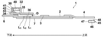
- FIG. 1 is a schematic perspective view of an immunochromatography kit 100 according to an embodiment of the present invention
- FIG. 2 is an exploded schematic perspective view of the immunochromatography kit 100 of FIG.
- the immunochromatographic kit 100 of this embodiment includes a test strip 1 that develops a sample solution and includes an insoluble carrier 2 having a test region of a test substance, and a detection signal in the test region.
- the housing case 9 is disposed between the lower case 20 having the accommodating portion 21 in which the test strip 1 is disposed, the upper case 10 joined to the lower case 20 at the periphery, and the upper case 10 and the lower case 20.
- the intermediate member 30 is provided.
- the upper case 10 side is defined as the upper side
- the lower case 20 side is defined as the lower side.
- the intermediate member 30 has a pot accommodating portion 32 having an amplification solution filling hole for receiving the first pot 40 and dropping the first amplification solution 41 on the insoluble carrier 2 on the bottom surface. Further, a protruding breakage portion 34 for breaking the sheet member 43 is provided at a position facing the sheet member 43 of the first pot 40 in the pot accommodating portion 32.
- the first pot 40 is arranged above the pot accommodating portion 32 so that the surface having the sheet member 43 is the lower surface, and the bottom surface of the pot accommodating portion 32 facing the sheet member 43. Is provided with a breaking portion 34 (see FIG. 3).
- a flow path forming portion 35 extending downstream from the bottom surface of the pot housing portion 32 of the intermediate member 30 is provided.
- the flow path forming unit 35 is arranged in alignment with the upper positions of the inspection region L 1 , the confirmation region L 2, and the amplification index region L 3 , and is a transparent material in order to make these regions L 1 to L 3 visible It is formed with.
- the upper case 10 is deformed to the first pot 40 side by applying a pressing force from the outside to a portion facing the first pot 40, and the sheet member 43 of the first pot 40 is moved to the intermediate member 30.
- the first convex deformation part 12 to be broken by the breaking part 34 is provided.
- the upper case 10 is deformed to the second pot 45 side by applying a pressing force from the outside to a portion facing the second pot 45, and the sheet member 48 of the second pot 45 is broken.
- Two convex deformation portions 14 are provided.
- the upper case 10 is provided with an opening 16 for dropping a sample droplet, from which the sample liquid is dropped onto the label holding pad 3 of the test strip 1.
- the upper case 10 includes an observation window 18 for visually recognizing the three regions L 1 to L 3 at a position corresponding to the flow path forming portion 35 of the intermediate member 30.
- the lower case 20 includes an insoluble carrier accommodating portion 21 on which the insoluble carrier 2 is placed and an absorbent pad accommodating portion 22 on which the absorbent pad 6 is placed on the downstream side as accommodating portions where the test strip 1 is disposed. Is provided.
- a second pot accommodating portion 24 in which the second pot 45 is accommodated is provided on the upstream side of the insoluble carrier accommodating portion 21.
- FIG. 3 is a schematic cross-sectional view showing the positional relationship between the test strip 1, the intermediate member 30, and the two pots 40 and 45.
- the test strip 1 includes an insoluble carrier 2 on which a sample solution is developed, and a labeling substance modified with a first substance that can bind to a test substance fixed on the insoluble carrier 2.
- the liquid feeding pad 4 for feeding the second amplification solution 46 arranged in contact with one end of the insoluble carrier 2 to the insoluble carrier 2, and the other end of the insoluble carrier 2
- the absorption pad 6 is provided.
- the insoluble carrier 2 is fixed and supported on the back adhesive sheet 7.
- the insoluble carrier 2 includes a test region L 1 containing a second substance that binds to the test substance and a confirmation region containing a substance that can bind to the first substance between the label holding pad 3 and the absorption pad 6.
- L 2 and an amplification index region L 3 containing a substance that reacts with the second amplification solution are sequentially provided from the label holding pad 3 side.
- the insoluble carrier 2 in which the examination region L 1 , the confirmation region L 2 and the amplification index region L 3 are formed may be referred to as a chromatographic carrier.
- the liquid-feeding pad 4 side is defined as upstream, and the absorption pad 6 side is defined as downstream.
- the intermediate member 30 is located in the upper part on the downstream end side of the test strip 1, and the first pot 40 is disposed in the pot accommodating portion 32 of the intermediate member 30 with the sheet member 43 facing down.
- the second pot 45 is accommodated below the upstream end of the test strip 1 of the lower case 20 with the sheet member 48 facing upward.
- a gap (clearance) D is formed between the back surface 36 of the flow path forming portion 35 of the intermediate member 30 and the insoluble carrier 2 of the test strip 1.
- This gap D is preferably in the range of 0.01 mm to 1 mm. If it is 0.01 mm or more, the amplification solution can be sufficiently infiltrated, and if it is 1 mm or less, the capillary force is exhibited, and the first amplification solution 41 uniformly fills the gap between the insoluble carrier 2 and the intermediate member 30. Is possible.
- the first pot 40 in which the first amplification liquid 41 is sealed for example, a container 42 having an opening on one surface made of a resin material is filled with the first amplification liquid 41, and the opening of the container 42 can be broken.
- the sheet member 43 is covered and sealed.
- the second pot 45 in which the second amplification liquid 46 is sealed the second amplification liquid 46 is filled in a container 47 having an opening on one surface made of, for example, a resin material, and the opening of the container 47 is opened. Covered and sealed by a breakable sheet member 48.
- a laminate film such as an aluminum foil or an aluminum laminated sheet is preferably used.
- the break means a state in which it is not regenerated after being broken.
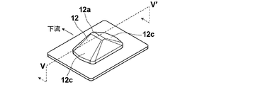
- FIG. 4 is a perspective view showing the first convex deformed portion 12
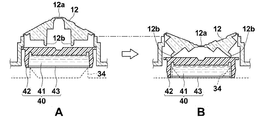
- FIG. 5 is a sectional view taken along the line VV ′ of FIG. 4, and FIG. Before the deformation of FIG. 5B, FIG. 5B shows the state after the deformation, and shows the positional relationship with the first pot 40.
- the first convex deformation portion 12 is configured to move the first pot 40 to a position where the sheet member 43 is broken by the breaking portion 34 of the intermediate member 30 by applying a pressing force. Specifically, the first convex deformation portion 12 is configured to be pushed downward by being pressed with a finger or the like, and the first convex deformation portion 12 is convex downward. In such a manner (when viewed from the outside, in a concave shape), the first pot is moved to a position where the sheet member 43 of the first pot 40 is broken by the breaking portion 34 in the pot housing portion 32 of the intermediate member 30. 40 is moved toward the breaking portion 34.
- the first amplification liquid 41 is dropped on the upper part of the insoluble carrier 2 from the amplification liquid filling hole provided in the bottom surface of the pot housing portion 32 of the intermediate member 30, and the inspection region L 1 , the confirmation region L 2 on the insoluble carrier, and amplification index regions L 3 it is possible to supply a first amplification solution 41.
- the first amplification solution 41 dropped from the amplification solution filling hole to the upper portion of the insoluble carrier 2 is filled in the gap between the intermediate member 30 and the insoluble carrier 2 and passes through the gap. 1 , supplied above the confirmation region L 2 and the amplification indicator region L 3 and gradually permeates the insoluble carrier 2.
- the first convex deformation portion 12 includes two projecting portions 12 b erected toward the first pot 40 at a position facing the first pot 40.
- the two protrusion portions 12b are in contact with the first pot 40 to move the first pot 40.
- the first convex deformed portion 12 has a centrally symmetric mountain shape, the two protrusions 12b are arranged symmetrically with respect to the mountain-shaped top 12a, and a slope sandwiching the top 12a. They are formed independently of each other below (rear surface) 12c.
- the two projecting portions 12b are positioned symmetrically with respect to the center of the contact surface of the first pot 40.
- the upper case 10 is formed.
- rupture part 34 of the intermediate member 30 is located under the sheet
- the interval between the two protrusions 12b is widened, and the tips of the two protrusions 12b are the contact surfaces of the first pot 40 with each other. It will be located in the edge part side rather than the half of the distance from the center to the edge part.
- the two protrusions 12b are provided independently, and there is a gap between the protrusions 12b (the back surface of the top 12a), and the convex deformation part 12 is formed of a flexible material. As a result, the first pot 40 is pushed down while greatly expanding the gap between the two protrusions 12b.
- the shape and arrangement of the protrusions 12b are not limited to the above-described forms.
- the two protrusions 12b are more than half the distance from the center to the end of the contact surface of the first pot 40. You may be provided in the position used as the side.
- the 1st convex deformation part 12 which moves the 1st pot 40, since there are two projection parts 12b, since the 1st pot 40 can be pushed equally in two places, the 1st The pot 40 can be moved in parallel.
- the first convex deformed portion 12 is easily deformed by pressing with a finger or the like, and the first convex deformed portion 12 becomes convex downward (concave shape). It is preferable that the concave shape does not return after this pressing and the first pot 40 can be kept pressed.
- the first convex deformation portion 12 is configured to press the top 12a, it can be similarly deformed by the elasticity of the convex deformation portion 12 by pressing a mountain-shaped slope.
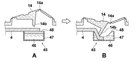
- FIG. 6 is a perspective view showing the second convex deformation portion 14
- FIG. 7 is a sectional view taken along the line VII-VII ′ of FIG. 6, and FIG.
- FIG. 7B shows the state after the deformation, and also shows the positional relationship with the second pot 45.
- the second convex deformation portion 14 is to break the sheet member 48 of the second pot 45 when a pressing force is applied.
- transformation part 14 is equipped with the one projection part 14b erected toward the 2nd pot 45 in the position facing the 2nd pot 45.
- a liquid feeding pad 4 of the test strip 1 is disposed between the second pot 45 and the second pot 45.
- a pressing force is applied to the second convex deformed portion 14 to project toward the second pot 45, that is, deform into a concave shape when viewed from the outside, and the projecting portion 14b is fed as shown in FIG. Abutting on the surface of the liquid pad 4, the sheet member 48 of the second pot 45 is pierced, and the liquid-feeding pad 4 is pushed into the second pot 45.
- the second convex deformation portion 14 has a mountain shape having a peak 14a on the slightly upstream side in a cross section along the upstream and downstream directions. Is inclined toward the downstream side to break through the sheet member 48.
- the liquid-feeding pad 4 is immersed in the amplification liquid 46 in the second pot 45, and the second amplification liquid 46 can penetrate into the liquid-feeding pad 4 by capillary action and be supplied to the insoluble carrier 2. It becomes.
- the second convex deformation portion 14 is also easily deformed into a concave shape by pressing with a finger or the like. It is preferable that the concave shape does not return after the pressing, and the liquid feeding pad 4 can be maintained in a state of being pushed into the second pot 45.
- the present invention realizes highly sensitive analysis by supplying the amplification liquid by deforming the first and second convex deformation parts without using a device connected to a power source. Is assumed to be deformed by hand. Accordingly, it is preferable that the amplification solution is designed not to accidentally leak to the outside, and the first and second convex deformation portions 12 and 14 provided in the upper case 10 are spaced from other portions of the upper case 10. It is preferable that they are integrally formed. It is preferable that the convex deformation parts 12 and 14 are made of a stretchable material and are joined to other parts of the upper case 10 in a sealed state.
- the first and second convex deformation portions 12 and 14 of the upper case 10 and the other portions may be separately manufactured and then joined to each other, but the first and second convex deformations may be used. It is preferable that the parts 12 and 14 are part of the upper case 10 and are integrally molded by injection molding as a single continuous member with no joints in the middle.
- the flexural modulus of the material constituting the convex deformation portions 12 and 14 is preferably 50 MPa or more and 350 MPa or less, and more preferably 70 MPa or more and 150 MPa or less.
- the liquid may leak from the gap, so that the fitting portion of the upper case 10 and the lower case 20 is also sealed. It is preferable that they are adhered.
- an adhesion method between the upper case 10 and the lower case 20 it is preferable to use an ultrasonic welding method. In general, ultrasonic welding is known to be difficult to weld unless the material to be welded is the same material.
- the combination of the upper case / lower case is polyethylene / polyethylene, polypropylene / polypropylene or ABS (acrylonitrile-butadiene-). Styrene copolymer) / ABS is good.
- the convex deformation parts 12 and 14 are formed integrally with the upper case 10, it is necessary that the material constituting the upper case 10 is flexible.
- the lower case 20 is preferably rigid to fix the test strip 1 and the second pot 45.
- the flexural modulus of the material constituting the upper case 10 is preferably 50 MPa or more and 350 MPa or less, and more preferably 70 MPa or more and 150 MPa or less.
- the bending elastic modulus of the material constituting the lower case 20 is preferably 500 MPa to 900 MPa, and particularly preferably 650 MPa to 750 MPa.
- the flexural modulus is a value calculated from equation (1) as follows in an environment at a temperature of 20 ° C. according to the measurement method of the ISO 178 standard.
- a plate-like test piece having a width b (mm) and a thickness h (mm) is prepared for the material for measuring the flexural modulus, and the test piece is supported by two fulcrums with a distance between the fulcrums of L (mm).
- a load of F (N) is applied to the center between the fulcrums, and the amount of deflection (mm) in the applied direction is measured.
- a deflection-load curve is created with the deflection S (mm) on the horizontal axis and the load F (N) on the vertical axis.
- the combination of the upper case / lower case is most preferably a polypropylene / polypropylene combination with a softener.
- the softening agent used for the polypropylene containing the softening agent is preferably an olefin-based elastomer, and the concentration of the olefin-based elastomer with respect to the polypropylene is preferably 20% by mass or more and 60% by mass or less, and particularly preferably 40% by mass or more and 55% by mass or less.
- Specific examples of the softening agent include Tough Selenium (registered trademark) manufactured by Sumitomo Chemical Co., Ltd.
- the immunochromatography kit of the present invention only needs to have two or more convex deformation parts.
- the convex deformation is accordingly performed. Three or more parts may be provided.
- the insoluble carrier 2 for example, a nitrocellulose membrane can be used.
- the back pressure-sensitive adhesive sheet 7 to which the insoluble carrier 2 is fixed is a sheet-like substrate whose surface to which the insoluble carrier 2 is attached is an adhesive surface.
- the label holding pad 3 is fixed to the central portion in the longitudinal direction of the insoluble carrier 2.
- a gold colloid EM.GC50, manufactured by BBI
- the surface of the labeling substance can be modified with a substance that binds to the test substance to form a conjugate with the test substance.
- the labeling substance is not limited to the above, and metal sulfides that can be used in ordinary chromatographic methods, colored particles that are used in immunoaggregation reactions, and the like can be used, and metal colloids are particularly preferable.
- metal colloids include gold colloids, silver colloids, platinum colloids, iron colloids, aluminum hydroxide colloids, and composite colloids thereof. In particular, at appropriate particle sizes, gold colloids are red and silver colloids are yellow. Of these, gold colloid is most preferable.
- test strip 1 is positioned such that the position of the sample droplet opening 16 in the upper case 10 and the label holding pad 3 coincide.
- Inspection area L 1 comprises a second substance that binds to the test substance is a labeling substance complementary region labeling substance bound to the test substance is supplemented via the analyte.
- a labeling substance complementary region labeling substance bound to the test substance is supplemented via the analyte.
- an anti-influenza A monoclonal antibody (Anti-Influenza A SPTN-5 7307, manufactured by Medix Biochemica) is formed into a line by physical adsorption. aspect which constitutes the examination region L 1 by antibody immobilization line being immobilized is preferred.
- This examination region L 1 and a test substance when complex labeling substance is bound through the first material reaches the second substance and a test substance to bind specifically, the test substance and the first material
- the labeling substance will be supplemented via this.
- the labeling substance does not constitute a complex of analyte passes through without being trapped in the examination region L 1.
- Confirmation area L 2 comprises a substance bound to the first substance, it is deployed insoluble carrier 2 medium with the sample liquid from the label holding pad 3, through labeling substance that has passed through the examination region L 1 is a first material This is an area for confirming the completion of the development of the sample liquid.
- a test substance for example, anti-mouse IgG antibody (anti-mouse IgG (H + L), rabbit F (ab ′) 2, product number 566-70621, Jun Wako)
- An embodiment in which Yakuhin Kogyo Co., Ltd.) is immobilized in a line by physical adsorption is preferred.
- Amplification index regions L 3 comprises a material that reacts with the second amplification solution 46, by color or color by reacting with a second amplification fluid 46 is changed, the second amplification fluid 46 is expanded to the area This is a region that indicates that the first amplification liquid 41 is dropped.
- a mixed aqueous solution of an aqueous iron nitrate solution and citric acid (manufactured by Wako Pure Chemical Industries, Ltd., 038-06925) is used as the second amplification solution, Bromocresol Green (Wako Pure Chemical Industries, Ltd.) ) Ltd.) is a mode to configure the amplification index regions L 3 by immobilized chromogenic reagent immobilization line in a line shape is preferred.
- region L 3 changes from green to orange. This discoloration can be captured as an indicator that the inspection region L 1 and the confirmation region L 2 are sufficiently filled with the second amplification liquid 46.
- a method of amplifying a signal of a metal-based labeling substance such as a metal colloid
- silver ions and a reducing agent for silver ions are brought into contact with the labeling substance, and silver ions are reduced by the reducing agent to generate silver particles.
- a method in which silver particles are deposited on a labeling substance using the labeling substance as a nucleus to amplify a signal from the labeling substance hereinafter referred to as silver amplification.
- a solution containing silver ions may be used as the first amplification solution 41
- a reducing agent solution containing a reducing agent for silver ions may be used as the second amplification solution 46.
- the solution containing silver ions used as the first amplification solution 41 is preferably a solution in which a silver ion-containing compound is dissolved in a solvent.
- a silver ion-containing compound an organic silver salt, an inorganic silver salt, or a silver complex can be used.
- it is an inorganic silver salt or a silver complex.
- a silver ion-containing compound having high solubility in a solvent such as water can be used, and examples thereof include silver nitrate, silver acetate, silver lactate, silver butyrate, and silver thiosulfate. Particularly preferred is silver nitrate.
- the silver complex is preferably a silver complex coordinated to a ligand having a water-soluble group such as a hydroxyl group or a sulfone group, and examples thereof include hydroxythioether silver.
- the reducing agent used in the reducing agent solution containing a reducing agent capable of reducing silver ions used as the second amplification solution 46 is inorganic or organic as long as it can reduce silver ions to silver. Any material or mixture thereof may be used.
- Preferred examples of the inorganic reducing agent include reducible metal salts and reducible metal complex salts whose valence can be changed by metal ions such as Fe 2+ , V 2+ and Ti 3+ .
- a complex of Fe 3+ which is an oxide can be formed using citric acid or EDTA (ethylenediaminetetraacetic acid), and can be rendered harmless.
- citric acid or EDTA ethylenediaminetetraacetic acid
- developing agents used in wet silver halide photographic materials for example, methyl gallate, hydroquinone, substituted hydroquinone, 3-pyrazolidones, p-aminophenols, p-phenylenediamines, hindered phenols, amidoximes
- Azines for example, catechols, pyrogallols, ascorbic acid (or derivatives thereof, and leuco dyes)
- other materials apparent to those skilled in the art such as those described in US Pat. No. 6,020,117 Can also be used.
- an ascorbic acid reducing agent is also preferable.
- useful ascorbic acid reducing agents include ascorbic acid analogs, isomers and derivatives thereof, such as D- or L-ascorbic acid and sugar derivatives thereof (eg ⁇ -lactoascorbic acid, glucoascorbic acid, fucoscorbic acid).
- Glucoheptascorbic acid, maltoascorbic acid sodium salt of ascorbic acid, potassium salt of ascorbic acid, isoascorbic acid (or L-erythroascorbic acid), salts thereof (eg alkali metal salts, ammonium salts or the art) Salt), enediol type ascorbic acid, enaminol type ascorbic acid, thioenol type ascorbic acid and the like, and particularly D, L or D, L-ascorbic acid (and Its alkali metal salt) Ku is isoascorbic acid (or alkali metal salts) is preferably, sodium salts are preferred salts. A mixture of these reducing agents can be used as necessary.
- the first convex deformation portion 12 moves the first pot 40 toward the fracture portion 34 provided in the intermediate member 30, but the first convex deformation
- the part 12 should just be the structure which can break the sheet
- the configuration of the first pot 40 and the housing portion 32 that houses the first pot 40 is not limited to the configuration of the present embodiment.
- the first convex member may have a single protrusion having the same shape as the second convex deformed portion of the above embodiment.
- a convex deformation part having the same shape as the second convex part deformation part may also be used as the first convex deformation part for moving the first pot 40.
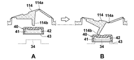
- FIG. 8 is a cut end view similar to FIG. 7 showing a form in which a deformable portion 114 having the same shape as the second convex deformable portion is used to move the first pot 40.
- the first pot 40 is disposed below the protrusion 114b of the convex deformation portion 114.
- a broken portion 34 of the intermediate member 30 is located below the first pot 40.
- the breaking portion 34 breaks through the sheet member 43 of the first pot 40, and the first amplification solution 41 enclosed in the first pot 40 flows out of the first pot and is supplied to the test strip 1.
- the in this way, the pot can be moved even if there is only one protrusion provided on the convex deformation portion 114.
- the immunochromatography kit of the present invention includes a pot containing a sample extract containing an auxiliary chemical that assists the extraction of the sample, a pot containing a sample diluent, a desiccant or an oxygen scavenger that helps preserve the kit, It may include package inserts such as instruction manuals and a set of equipment necessary for inspection of a sample collection instrument such as a cotton swab or a part thereof.
- An immunochromatographic inspection method using the immunochromatographic kit 100 will be briefly described.
- a sample solution is dropped onto the label holding pad 3 from the opening 16 for dropping the sample droplet.
- the test substance and the first substance are bonded to each other in the label holding pad 3 so that the test substance and the label substance through the first substance are bonded.
- a complex is formed, and this complex is developed together with the sample solution toward the absorption pad 6 side by capillary action by the suction force of the absorption pad 6.
- the second convex deformation portion 14 is pressed down to displace the liquid-feeding pad 4 to break the sheet member 48 of the second pot 45, and the liquid-feeding pad 4
- the second amplification solution 46 is immersed in the second amplification solution 46 and sent to the insoluble carrier 2.
- the timing of pressing the second convex deformation portion 14 is preferably within 30 seconds from the time when the sample liquid is dropped, and particularly preferably immediately after the dropping of the sample liquid.
- Complex reaches the examination region L 1 is captured combined with a second material of the examination region L 1.
- the first materials not bound to the analyte reaches the verification area L 2 passes through the examination region L 1, binds to the captured as a substance that binds to the first substance confirmation area L 2 .
- Second amplification fluid 46 reaches the examination region L 1, amplification index regions L 3 through the check region L 2. At this time, when the amplification index region L 3 changes color, it is possible to visually recognize the arrival of the second amplification liquid 46 to the amplification index region L 3 . After confirming the discoloration of the amplification index region L 3 , the first convex deformation portion 12 is pressed to supply the first amplification solution 41 onto the insoluble carrier 2.
- the completion of the reaction is awaited, and the color development in the inspection region L 1 and the confirmation region L 2 is confirmed from the observation window 18.
- the color of the inspection area L 1 can ascertain the level of presence and concentration of the analyte, that test that measures the analyte by coloring the confirmation area L 2 To verify that successful it can.
- Color in the examination region L 1 and confirmation area L 2 are those obtained by amplifying the signal of the label, it is possible to realize a high-sensitivity examination.
- the immunochromatography kits of Examples and Comparative Examples are immunochromatography kits for detecting influenza virus antigens for detecting influenza virus antigens as test substances.
- the supernatant liquid was removed leaving 1 mL at the bottom of the container, and the gold colloid contained in the 1 mL liquid remaining at the bottom of the container was redispersed by an ultrasonic cleaner. Then, it is dispersed in 20 mL of colloidal gold stock solution (20 mmol / L Tris-HCl (Tris-HCl) buffer (pH 8.2), 0.05% PEG (Mw. 20000), 150 mmol / L NaCl, 1% BSA). Centrifugation was again performed under the same conditions using the same centrifuge, and the supernatant was removed. After ultrasonic dispersion, the solution was dispersed in a gold colloid preservation solution to obtain an antibody-modified gold colloid (50 nm) solution.
- colloidal gold stock solution (20 mmol / L Tris-HCl (Tris-HCl) buffer (pH 8.2), 0.05% PEG (Mw. 20000), 150 mmol / L NaCl, 1% BSA). Centr
- This coating solution is uniformly applied at 0.8 mL per glass fiber pad (Glass Fiber Conjugate Pad, manufactured by Millipore) cut to 12 mm x 300 mm, and dried for 24 hours under reduced pressure to retain influenza A antibody-modified gold colloid I got a pad.
- Glass Fiber Conjugate Pad manufactured by Millipore
- Anti-influenza A monoclonal antibody (Anti-Influenza A SPTN-5 7307, manufactured by Medix Biochemica) prepared at a position 15 mm from the downstream side of the 60-mm short side of the nitrocellulose membrane at 1.5 mg / mL ) The solution was applied in a line to form an inspection area. Furthermore, an anti-mouse IgG antibody (anti-mouse IgG (H + L), rabbit F (ab ′) 2, part number 566 ⁇ ) prepared to be 0.2 mg / mL at a position 11 mm from the downstream side of the short side of 60 mm. 70621 (manufactured by Wako Pure Chemical Industries, Ltd.) was applied in a line to form a confirmation region.
- Bromocresol Green (manufactured by Wako Pure Chemical Industries, Ltd.) prepared at 30 mmol / L was applied in a line at a position 9 mm from the downstream side of the short side of 60 mm to form an amplification index region.
- the nitrocellulose membrane was dried at 50 ° C. for 30 minutes with a hot air dryer.
- a blocking solution 50 mmol / L borate buffer (pH 8.5) containing 0.5% by mass of casein (derived from milk, product number 030-01505, manufactured by Wako Pure Chemical Industries, Ltd.)
- the nitrose membrane dried as described above was immersed in a 500 mL bat and allowed to stand for 30 minutes.
- nitrocellulose membrane was taken out, and a cleaning / stabilizing solution prepared in another vat (50 mmol / L Tris-HCl (pH 7.5) buffer containing 0.5 mass% sucrose and 0.05 mass% sodium cholate)
- a cleaning / stabilizing solution prepared in another vat 50 mmol / L Tris-HCl (pH 7.5) buffer containing 0.5 mass% sucrose and 0.05 mass% sodium cholate
- the nitrocellulose membrane was immersed in 500 mL and allowed to stand for 30 minutes. Thereafter, the nitrocellulose membrane was taken out of the liquid and dried in an environment at 25 ° C. for 24 hours.
- a test region in which the portion to which the anti-influenza A antibody is immobilized contains a second substance that binds to the test substance, and a confirmation region in which the part to which the anti-mouse IgG antibody is immobilized contains a substance that can bind to the first substance ,
- a liquid-feeding pad (glass fiber pad (Glass Fiber Conjugate Pad, manufactured by Millipore) cut to 25 mm ⁇ 300 mm) was attached to the upstream side of the chromatographic carrier so that the liquid-feeding pad and the chromatographic carrier overlapped by 7 mm. .
- the member thus produced was cut with a guillotine cutter (CM4000, manufactured by NIPPN Technocluster Co., Ltd.) so that the width was 5 mm parallel to the direction perpendicular to the long side of 300 mm, and 60 test strips ( However, the absorbent pad was not included.
- nitric acid (10 wt%) 5.9 mL, dodecylamine (Wako Pure Chemical Industries Co., Ltd., 123-00246) 0.1 g, surfactant C 12 H 25 -C 6 H 4 -
- 0.1 g of O— (CH 2 CH 2 O) 50 H was previously dissolved in 47.6 g of water was mixed, and this was used as a silver ion solution as a first amplification solution sealed in the first pot. .
- the upper case was produced by injection molding using polypropylene containing 50% by mass of Tough Selenium (registered trademark), which is an olefin elastomer manufactured by Sumitomo Chemical Co., Ltd., as a material.
- the upper case 10 includes two deformable portions (a first convex deformation portion and a second convex deformation portion), and these two deformation portions do not have a part that separates from the upper case 10, It was produced by injection molding as part of the upper case 10 at all boundaries.
- the first convex deformation portion 12 shown in FIGS. 1 and 2 and the like has two protrusions, and the second convex deformation portion 14 has one protrusion. It was set as the structure which has.
- the upper case of Example 2 was configured to include two convex deformed portions having only one protrusion having the same shape as the second convex deformed portion 14 shown in FIGS. That is, as shown in FIG. 8, the upper case of the second embodiment includes the first convex deformation portion 114 above the first pot 40 and the second convex shape above the second pot 45.
- the deformation portion 14 is provided.
- the flexural modulus of the material of the upper case and the lower case was 90 (MPa) and 700 (MPa), respectively.
- Table 1 shows the result of the same test repeated five times for each example.
- the supply amount of the silver ion solution was determined according to the following criteria.
- A: 40 ⁇ L or more B: 20 ⁇ L or more and less than 40 ⁇ L C: less than 20 ⁇ L ⁇ OD was determined according to the following criteria.
- Amplification can be performed accurately and sufficient analysis is possible.
- both the immunochromatographic kits of Example 1 and Example 2 are within the allowable ranges for both the supply amount of the first amplification solution and the value of ⁇ OD and can be sufficiently amplified. .
- the first pot 40 in which there are two projections of the first convex member that pushes the first pot 40, the first pot 40 can be pushed with a flat surface, and the silver ion solution is stably more than the target amount Thus, the amplification reaction could be stably carried out stably.
- the variation coefficient CV of ⁇ OD in Example 1 was as low as 10%, and that the shape having two protrusions could be measured with high accuracy.
- the measurement result of ⁇ OD in the table is consistent with the evaluation result when visually evaluated, and the solution necessary for increasing the sensitivity of the amplification solution, etc. without using a device that uses a power source such as an analyzer.
- An immunochromatography kit capable of supplying
Abstract
[Problem] To provide an immunochromatography kit with which high-sensitivity measurements are made without needing a dedicated analysis device. [Solution] A housing case (9) for encasing a test strip (1), a first pot (40) in which a first amplification liquid (41) is sealed, and a second pot (45) in which a second amplification fluid (46) is sealed is provided with a lower case (20), an upper case (10), and an intermediate member (30) positioned between the lower case (20) and the upper case (10). The upper case (10) is provided with a first convex deformation part (12) in a portion facing the first pot (40), and a second convex deformation part (14) in a portion facing the second pot (45). The first convex deformation part (12) is configured so as to deform toward the first pot (40) as a result of a pressing force being applied from the outside, and a sheet member (43) of the first pot (40) is broken by a breaking part (34) of the intermediate member (30). The second convex deformation part (14) is configured so as to deform toward the second pot (45) and break a sheet member (48) of the second pot (45) due to a pressing force being applied from the outside.
Description
本発明は、イムノクロマトグラフキットに関し、特に、検出感度を高めるためのシグナル増幅操作を行うイムノクロマトグラフキットに関する。
The present invention relates to an immunochromatography kit, and more particularly, to an immunochromatography kit that performs a signal amplification operation for increasing detection sensitivity.
免疫測定方法の中でもイムノクロマトグラフ法は、操作が簡便であり短時間で測定可能であることから、簡易な被検物質検出方法として一般に利用されている。
Among immunoassay methods, the immunochromatography method is generally used as a simple test substance detection method because it is easy to operate and can be measured in a short time.
イムノクロマトグラフ法で用いられている免疫反応としては、競合的反応またはサンドイッチ型反応が広く使われている。その中でも、サンドイッチ型反応が主流であり、典型的な検査方法は次の通りである。
Competitive reaction or sandwich type reaction is widely used as an immune reaction used in immunochromatography. Among them, the sandwich type reaction is the mainstream, and a typical inspection method is as follows.
まず、被検出物質である抗原に対する抗体により感作させた微粒子を固相微粒子としてクロマトグラフ担体に固定化することにより、あるいは抗体自体をクロマトグラフ担体に直接固定化することにより、反応部位を有するクロマトグラフ担体を作製する。また、標識微粒子に被検出物質と特異的に結合可能な抗体を感作させて感作標識微粒子を調製する。
そして、この感作標識微粒子を試料と共に、クロマトグラフ担体上でクロマトグラフ的に移動させることにより、クロマトグラフ担体の反応部位において、固定化されている抗体に被検出物質である抗原を介して感作標識微粒子が特異的に結合し、その結果、感作標識微粒子が反応部位に捕捉される。この反応部位に捕捉された感作標識微粒子により生ずるシグナルの有無または程度を目視で判定することにより、試料中の被検出物質の存在の有無または量を測定することができる。 First, it has a reactive site by immobilizing fine particles sensitized with an antibody against the antigen to be detected as a solid phase fine particle on a chromatographic carrier, or by immobilizing the antibody itself directly on the chromatographic carrier. A chromatographic carrier is prepared. In addition, sensitized labeled microparticles are prepared by sensitizing an antibody capable of specifically binding to the substance to be detected to the labeled microparticles.
Then, the sensitized labeled fine particles are moved together with the sample chromatographically on the chromatographic carrier, so that the immobilized antibody is sensitized to the immobilized antibody via the antigen to be detected at the reaction site of the chromatographic carrier. The labeled microparticles specifically bind, and as a result, the sensitized labeled microparticles are captured at the reaction site. The presence / absence or amount of the substance to be detected in the sample can be measured by visually determining the presence / absence or degree of the signal generated by the sensitized labeled fine particles trapped at the reaction site.
このようなイムノクロマトグラフ法においては、被検出物質が含まれているにも関わらず感度が低いために検出されず偽陰性を示すという問題を回避するために、検出シグナルを増幅させる技術が提案されている。シグナル増幅の方法として、標識としてアルカリフォスファターゼ、ペルオキシダーゼなどの酵素を用いる技術が特許文献1、2等に開示されている。また、特許文献3には、金属コロイド標識および金属硫化物標識からなる群から選んだ標識に銀を含む化合物および銀イオンのための還元剤を用いて増感すること(銀増幅)によって検出を行う技術により、より高感度で抗原の量が少ない場合でも検出が可能な技術が開示されている。
In such an immunochromatography method, a technique for amplifying a detection signal has been proposed in order to avoid the problem that false negatives are not detected due to low sensitivity despite the presence of a substance to be detected. ing. As a method for signal amplification, techniques using an enzyme such as alkaline phosphatase or peroxidase as a label are disclosed in Patent Documents 1 and 2 and the like. Patent Document 3 discloses detection by sensitizing a label selected from the group consisting of a metal colloid label and a metal sulfide label with a compound containing silver and a reducing agent for silver ions (silver amplification). According to the technique to be performed, a technique is disclosed that can be detected even when the sensitivity is high and the amount of antigen is small.
特許文献3に開示されている銀増幅による検出シグナルの増幅方法によれば、非常に高感度な検出が可能となる。この銀増幅方法においては、銀イオン還元剤を含む溶液のような増幅を触媒する液と、銀イオンを含む溶液のような増幅を行う液との2種類の液をイムノクロマトグラフ担体に供給する必要がある。
According to the method for amplifying a detection signal by silver amplification disclosed in Patent Document 3, detection with very high sensitivity becomes possible. In this silver amplification method, it is necessary to supply an immunochromatographic carrier with two kinds of liquids, a liquid that catalyzes amplification such as a solution containing a silver ion reducing agent and a liquid that performs amplification such as a solution containing silver ions. There is.
特許文献3に記載のイムノクロマトグラフ担体を収容するデバイスは、電源により作動する分析装置などにセットして、分析装置に設けられている外力付与機構などの操作により増幅液の供給を行うことを前提として形成されている。そのため、電源により作動する専用の分析装置は、緊急災害時などの電気のインフラが停止した状況や、電気の通じていない環境では使用できない、などの不具合が生じる場合がある。
The device that accommodates the immunochromatographic carrier described in Patent Document 3 is set on an analyzer that is operated by a power source, and the amplification liquid is supplied by an operation of an external force imparting mechanism that is provided in the analyzer. It is formed as. For this reason, the dedicated analyzer operated by the power source may cause problems such as a situation where the electrical infrastructure is stopped during an emergency disaster or the use of it in an environment where electricity is not connected.
本発明は、上記事情に鑑みてなされたものであって、専用の分析装置を必要とせず高感度な測定が実現可能なイムノクロマトグラフキットを提供することを目的とする。
The present invention has been made in view of the above circumstances, and an object of the present invention is to provide an immunochromatographic kit capable of realizing highly sensitive measurement without requiring a dedicated analyzer.
本発明のイムノクロマトグラフキットは、試料液中の被検物質を検出するイムノクロマトグラフキットであって、
試料液を展開させる、被検物質の検査領域を有する不溶性担体を含む検査用ストリップと、
検査領域における検出信号を増幅するための、第1の増幅液および第2の増幅液がそれぞれ封入された、シート部材を備えた一面を有する第1のポットおよび第2のポットと、
検査用ストリップ、第1のポットおよび第2のポットを内包するハウジングケースとを備え、
ハウジングケースが、検査用ストリップが配置される収容部を備えた下部ケースと、下部ケースと周縁で接合された上部ケースと、上部ケースと下部ケースとの間に配置された中間部材とを備えてなり、
中間部材が、第1のポットのシート部材を破断する破断部を、第1のポットのシート部材に面して備え、
上部ケースが、第1のポットに対向する部分に、外部から押圧力が加えられることにより、第1のポット側に変形して、第1のポットのシート部材を中間部材の破断部により破断する第1の凸状変形部と、第2のポットに対向する部分に、外部から押圧力を加えることにより、第2のポット側に変形して第2のポットのシート部材を破断する第2の凸状変形部とを備えてなるイムノクロマトグラフキットである。 The immunochromatographic kit of the present invention is an immunochromatographic kit for detecting a test substance in a sample solution,
A test strip containing an insoluble carrier having a test region of a test substance for developing a sample solution;
A first pot and a second pot each having a sheet member, each of which is filled with a first amplification liquid and a second amplification liquid for amplifying a detection signal in the inspection region;
A test strip, a housing case containing the first pot and the second pot,
The housing case includes a lower case having a receiving portion in which the test strip is disposed, an upper case joined to the lower case at the periphery, and an intermediate member disposed between the upper case and the lower case. Become
The intermediate member includes a breaking portion that breaks the sheet member of the first pot, facing the sheet member of the first pot,
The upper case is deformed to the first pot side when a pressing force is applied from the outside to a portion facing the first pot, and the sheet member of the first pot is broken by the breaking portion of the intermediate member. By applying a pressing force from the outside to the first convex deformation portion and the portion facing the second pot, the second convex portion deforms to the second pot side and breaks the sheet member of the second pot. It is an immunochromatography kit provided with a convex deformation part.
本発明のイムノクロマトグラフキットにおいては、第1の凸状変形部が、押圧力が加えられることにより、第1のポットを、シート部材が中間部材の破断部により破断される位置まで移動させるものであることが好ましい。
このとき、上部ケースが、第1の凸状変形部に押圧力を加えた際に第1のポットに当接して移動させる、第1のポット側に向かって立設された2つの突起部を備えることが好ましい。 In the immunochromatography kit of the present invention, the first convex deformation portion moves the first pot to a position where the sheet member is broken by the breaking portion of the intermediate member by applying a pressing force. Preferably there is.
At this time, when the upper case applies a pressing force to the first convex deformation portion, the two protrusions erected toward the first pot are moved so as to come into contact with the first pot and move. It is preferable to provide.
本発明のイムノクロマトグラフキットにおいては、第1の凸状変形部が中央対称な山型形状を有していることが好ましい。
また、このとき、2つの突起部が、山型形状の頂上に対して対称に配置されていることが好ましい。
また、2つの突起部が、山型形状の頂上を挟む斜面に互いに独立して形成されていることも好ましい。 In the immunochromatography kit of the present invention, it is preferable that the first convex deformation portion has a centrally symmetrical mountain shape.
At this time, it is preferable that the two protrusions are arranged symmetrically with respect to the top of the mountain shape.
It is also preferable that the two protrusions are formed independently of each other on the slope sandwiching the top of the mountain shape.
本発明のイムノクロマトグラフキットにおいては、第1の凸状変形部が上述の2つの突起部を備えているとき、この2つの突起部が、第1のポットの当接面の中央に対して対称に配置されていることが好ましい。
また、2つの突起部が、第1のポットの当接面の中央から端部までの距離の半分よりも端部側に配置されていることが好ましい。 In the immunochromatography kit of the present invention, when the first convex deformation portion includes the two protrusions described above, the two protrusions are symmetrical with respect to the center of the contact surface of the first pot. It is preferable to arrange | position.
Moreover, it is preferable that two protrusion parts are arrange | positioned at the edge part side rather than the half of the distance from the center of the contact surface of a 1st pot to an edge part.
なお、本明細書において凸状変形部は、イムノクロマトグラフキットの外部から見た場合に凸状であることを意味する、また、山型形状も同様に、外部から見て山型であることを意味する。
In the present specification, the convex deformed portion means a convex shape when viewed from the outside of the immunochromatography kit, and the mountain shape is also a mountain shape when viewed from the outside. means.
本発明のイムノクロマトグラフキットにおいては、第1の凸状変形部が上述の2つの突起部を備えているとき、この2つの突起部のそれぞれの先端が第1のポットに当接し、徐々に端部側に変位しつつ第1のポットを移動させるように構成することができる。
In the immunochromatography kit of the present invention, when the first convex deformed portion includes the above-described two protrusions, the tips of the two protrusions abut against the first pot, and the end gradually The first pot can be moved while being displaced toward the part.
本発明のイムノクロマトグラフキットにおいては、第1の凸状変形部を構成する材質の曲げ弾性率が50MPa~350MPaであることが好ましい。
また、上部ケースを構成する材質の曲げ弾性率が50MPa~350MPaであり、下部ケースを構成する材質の曲げ弾性率が500MPa~900MPaであることが好ましい。 In the immunochromatographic kit of the present invention, the material constituting the first convex deformed portion preferably has a flexural modulus of 50 MPa to 350 MPa.
In addition, the bending elastic modulus of the material constituting the upper case is preferably 50 MPa to 350 MPa, and the bending elastic modulus of the material constituting the lower case is preferably 500 MPa to 900 MPa.
本発明のイムノクロマトグラフキットにおいては、上部ケースが、射出成形により第1の凸状変形部および第2の凸状変形部を一体的に形成されてなるものであることが好ましい。
In the immunochromatographic kit of the present invention, it is preferable that the upper case is formed by integrally forming the first convex deformation portion and the second convex deformation portion by injection molding.
本発明のイムノクロマトグラフキットは、上部ケースが、第1のポットに対向する部分に、外部から押圧力が加えられることにより、第1のポット側に変形して、第1のポットのシート部材を中間部材の破断部により破断する第1の凸状変形部と、第2のポットに対向する部分に、外部から押圧力を加えることにより、第2のポット側に変形して第2のポットのシート部材を破断する第2の凸状変形部とを備え、2つの凸状変形部にヒトが指等で押圧力を加えることで、変形させて、ポットのシート部材を破断させることができ、増幅液を検査用ストリップに供給することができるため、電源を要する専用の分析装置がなくても、増幅反応を正常に行うことができる。従って本発明のイムノクロマトグラフキットは専用の分析装置を備えていない、あるいは分析装置が使用できない非常時、災害時等において特に有用である。
In the immunochromatography kit of the present invention, the upper case is deformed to the first pot side by applying a pressing force from the outside to the portion facing the first pot, so that the sheet member of the first pot is By applying a pressing force from the outside to the first convex deformation portion that is broken by the break portion of the intermediate member and the portion facing the second pot, the second pot is deformed to the second pot side. A second convex deformation part that breaks the sheet member, and a person applies a pressing force to the two convex deformation parts with a finger or the like to deform and break the sheet member of the pot, Since the amplification solution can be supplied to the test strip, the amplification reaction can be normally performed without a dedicated analyzer that requires a power source. Therefore, the immunochromatographic kit of the present invention is particularly useful in an emergency, disaster, or the like in which no dedicated analyzer is provided or the analyzer cannot be used.
以下、本発明の実施形態について図面を用いて説明するが、本発明はこれに限られるものではない。なお、視認しやすくするため、図面中の各構成要素の縮尺等は実際のものとは適宜変化させてある。
Hereinafter, embodiments of the present invention will be described with reference to the drawings, but the present invention is not limited thereto. In addition, in order to make it easy to visually recognize, the scale of each component in the drawings is appropriately changed from the actual one.
図1は、本発明の実施形態にかかるイムノクロマトグラフキット100の概略斜視図であり、図2は、図1のイムノクロマトグラフキット100の分解概略斜視図である。
図1および図2に示すように、本実施形態のイムノクロマトグラフキット100は、試料液を展開させる、被検物質の検査領域を有する不溶性担体2を含む検査用ストリップ1と、検査領域における検出信号を増幅するための、第1の増幅液41および第2の増幅液46がそれぞれ封入された、シート部材を備えた一面を有する第1のポット40および第2のポット45とがハウジングケース9に内包されてなる。ハウジングケース9は、検査用ストリップ1が配置される収容部21を備えた下部ケース20と、下部ケース20と周縁で接合された上部ケース10と、上部ケース10と下部ケース20との間に配置された中間部材30とを備えてなる。なお、本イムノクロマトグラフキット100を説明するに当たっては、上部ケース10側を上、下部ケース20側を下と定義する。 FIG. 1 is a schematic perspective view of animmunochromatography kit 100 according to an embodiment of the present invention, and FIG. 2 is an exploded schematic perspective view of the immunochromatography kit 100 of FIG.
As shown in FIGS. 1 and 2, theimmunochromatographic kit 100 of this embodiment includes a test strip 1 that develops a sample solution and includes an insoluble carrier 2 having a test region of a test substance, and a detection signal in the test region. A first pot 40 and a second pot 45 having a sheet member, each of which is filled with a first amplification liquid 41 and a second amplification liquid 46, are provided in the housing case 9. It is included. The housing case 9 is disposed between the lower case 20 having the accommodating portion 21 in which the test strip 1 is disposed, the upper case 10 joined to the lower case 20 at the periphery, and the upper case 10 and the lower case 20. The intermediate member 30 is provided. In describing the immunochromatography kit 100, the upper case 10 side is defined as the upper side, and the lower case 20 side is defined as the lower side.
図1および図2に示すように、本実施形態のイムノクロマトグラフキット100は、試料液を展開させる、被検物質の検査領域を有する不溶性担体2を含む検査用ストリップ1と、検査領域における検出信号を増幅するための、第1の増幅液41および第2の増幅液46がそれぞれ封入された、シート部材を備えた一面を有する第1のポット40および第2のポット45とがハウジングケース9に内包されてなる。ハウジングケース9は、検査用ストリップ1が配置される収容部21を備えた下部ケース20と、下部ケース20と周縁で接合された上部ケース10と、上部ケース10と下部ケース20との間に配置された中間部材30とを備えてなる。なお、本イムノクロマトグラフキット100を説明するに当たっては、上部ケース10側を上、下部ケース20側を下と定義する。 FIG. 1 is a schematic perspective view of an
As shown in FIGS. 1 and 2, the
中間部材30は、第1のポット40を受容し、第1の増幅液41を不溶性担体2上に滴下させるための増幅液充填孔を底面に備えたポット収容部32を有している。また、ポット収容部32内の第1のポット40のシート部材43に面する位置にシート部材43を破断する突起状の破断部34が設けられている。本例においては、ポット収容部32の上方に第1のポット40が、そのシート部材43を有する面が下面となるように配置されており、そのシート部材43に対向するポット収容部32の底面に破断部34が設けられている(図3参照)。
また中間部材30のポット収容部32の底面の下流側に延在する流路形成部35を備えている。流路形成部35は、検査領域L1、確認領域L2および増幅指標領域L3の上方位置に一致して配置され、これらの領域L1~L3を視認可能とするために透明な材料で形成されている。 Theintermediate member 30 has a pot accommodating portion 32 having an amplification solution filling hole for receiving the first pot 40 and dropping the first amplification solution 41 on the insoluble carrier 2 on the bottom surface. Further, a protruding breakage portion 34 for breaking the sheet member 43 is provided at a position facing the sheet member 43 of the first pot 40 in the pot accommodating portion 32. In this example, the first pot 40 is arranged above the pot accommodating portion 32 so that the surface having the sheet member 43 is the lower surface, and the bottom surface of the pot accommodating portion 32 facing the sheet member 43. Is provided with a breaking portion 34 (see FIG. 3).
Further, a flowpath forming portion 35 extending downstream from the bottom surface of the pot housing portion 32 of the intermediate member 30 is provided. The flow path forming unit 35 is arranged in alignment with the upper positions of the inspection region L 1 , the confirmation region L 2, and the amplification index region L 3 , and is a transparent material in order to make these regions L 1 to L 3 visible It is formed with.
また中間部材30のポット収容部32の底面の下流側に延在する流路形成部35を備えている。流路形成部35は、検査領域L1、確認領域L2および増幅指標領域L3の上方位置に一致して配置され、これらの領域L1~L3を視認可能とするために透明な材料で形成されている。 The
Further, a flow
上部ケース10は、第1のポット40に対向する部分に、外部から押圧力が加えられることにより、第1のポット40側に変形してその第1のポット40のシート部材43を中間部材30の破断部34により破断させる第1の凸状変形部12を備えている。また、上部ケース10は、第2のポット45に対向する部分に、外部から押圧力を加えることにより、第2のポット45側に変形して第2のポット45のシート部材48を破断する第2の凸状変形部14を備えている。
また、上部ケース10には、試料液滴下用開孔16が設けられており、この開孔16から検査用ストリップ1の標識保持パッド3上に試料液が滴下される。開孔16と標識保持パッド3との位置が一致するように、標識保持パッド3の位置を調整することで、標識保持パッド3上に確実に試料液を点着することが可能となる。また、上部ケース10は、中間部材30の流路形成部35に対応する位置に3つの領域L1~L3を視認するための観察窓18を備えている。 Theupper case 10 is deformed to the first pot 40 side by applying a pressing force from the outside to a portion facing the first pot 40, and the sheet member 43 of the first pot 40 is moved to the intermediate member 30. The first convex deformation part 12 to be broken by the breaking part 34 is provided. Further, the upper case 10 is deformed to the second pot 45 side by applying a pressing force from the outside to a portion facing the second pot 45, and the sheet member 48 of the second pot 45 is broken. Two convex deformation portions 14 are provided.
Theupper case 10 is provided with an opening 16 for dropping a sample droplet, from which the sample liquid is dropped onto the label holding pad 3 of the test strip 1. By adjusting the position of the marker holding pad 3 so that the positions of the opening 16 and the marker holding pad 3 coincide with each other, the sample liquid can be reliably spotted on the marker holding pad 3. Further, the upper case 10 includes an observation window 18 for visually recognizing the three regions L 1 to L 3 at a position corresponding to the flow path forming portion 35 of the intermediate member 30.
また、上部ケース10には、試料液滴下用開孔16が設けられており、この開孔16から検査用ストリップ1の標識保持パッド3上に試料液が滴下される。開孔16と標識保持パッド3との位置が一致するように、標識保持パッド3の位置を調整することで、標識保持パッド3上に確実に試料液を点着することが可能となる。また、上部ケース10は、中間部材30の流路形成部35に対応する位置に3つの領域L1~L3を視認するための観察窓18を備えている。 The
The
下部ケース20には、検査用ストリップ1が配置される収容部として、不溶性担体2が載置される不溶性担体収容部21およびその下流側に吸収パッド6が載置される吸収パッド収容部22が設けられている。また、不溶性担体収容部21の上流側には第2のポット45が収容される第2のポット収容部24が設けられている。
The lower case 20 includes an insoluble carrier accommodating portion 21 on which the insoluble carrier 2 is placed and an absorbent pad accommodating portion 22 on which the absorbent pad 6 is placed on the downstream side as accommodating portions where the test strip 1 is disposed. Is provided. In addition, a second pot accommodating portion 24 in which the second pot 45 is accommodated is provided on the upstream side of the insoluble carrier accommodating portion 21.
図3は、検査用ストリップ1、中間部材30および2つのポット40、45の位置関係を示す模式的断面図である。検査用ストリップ1は、図3に示すように、試料液を展開させる不溶性担体2と、不溶性担体2上に固定された被検物質に結合可能な第1の物質で修飾された標識物質を含む標識保持パッド3と、不溶性担体2の一端に接触して配置された第2の増幅液46を不溶性担体2に送液する送液用パッド4と、不溶性担体2の他端に接触して配置された吸収パッド6とを備えている。不溶性担体2はバック粘着シート7上に固定されて支持されている。そして、不溶性担体2は、標識保持パッド3と吸収パッド6との間に、被検物質に結合する第2の物質を含む検査領域L1、第1の物質に結合可能な物質を含む確認領域L2、第2の増幅液と反応する物質を含む増幅指標領域L3を標識保持パッド3側から順に有する。
FIG. 3 is a schematic cross-sectional view showing the positional relationship between the test strip 1, the intermediate member 30, and the two pots 40 and 45. As shown in FIG. 3, the test strip 1 includes an insoluble carrier 2 on which a sample solution is developed, and a labeling substance modified with a first substance that can bind to a test substance fixed on the insoluble carrier 2. Placed in contact with the label holding pad 3, the liquid feeding pad 4 for feeding the second amplification solution 46 arranged in contact with one end of the insoluble carrier 2 to the insoluble carrier 2, and the other end of the insoluble carrier 2 The absorption pad 6 is provided. The insoluble carrier 2 is fixed and supported on the back adhesive sheet 7. The insoluble carrier 2 includes a test region L 1 containing a second substance that binds to the test substance and a confirmation region containing a substance that can bind to the first substance between the label holding pad 3 and the absorption pad 6. L 2 and an amplification index region L 3 containing a substance that reacts with the second amplification solution are sequentially provided from the label holding pad 3 side.
なお、本明細書において検査領域L1、確認領域L2および増幅指標領域L3が形成されてなる不溶性担体2をクロマトグラフ担体と称する場合がある。また、本明細書においては、図3に記載のように送液用パッド4側を上流、吸収パッド6側を下流として定義する。
In the present specification, the insoluble carrier 2 in which the examination region L 1 , the confirmation region L 2 and the amplification index region L 3 are formed may be referred to as a chromatographic carrier. In the present specification, as shown in FIG. 3, the liquid-feeding pad 4 side is defined as upstream, and the absorption pad 6 side is defined as downstream.
中間部材30は検査用ストリップ1の下流端側の上部に位置されており、第1のポット40はシート部材43を下にして、中間部材30のポット収容部32中に配置されている。第2のポット45はシート部材48を上にして、下部ケース20の検査用ストリップ1の上流端の下方に収容されている。
The intermediate member 30 is located in the upper part on the downstream end side of the test strip 1, and the first pot 40 is disposed in the pot accommodating portion 32 of the intermediate member 30 with the sheet member 43 facing down. The second pot 45 is accommodated below the upstream end of the test strip 1 of the lower case 20 with the sheet member 48 facing upward.
図3に示されているように、中間部材30の流路形成部35の裏面36と、検査用ストリップ1の不溶性担体2との間には、隙間(クリアランス)Dが形成される。この隙間Dは0.01mm~1mmの範囲にあることが好ましい。0.01mm以上であれば増幅液等を充分浸潤させることができ、1mm以下であれば毛細管力が発揮され、第1の増幅液41により不溶性担体2と中間部材30の隙間を均一に満たすことが可能である。
3, a gap (clearance) D is formed between the back surface 36 of the flow path forming portion 35 of the intermediate member 30 and the insoluble carrier 2 of the test strip 1. This gap D is preferably in the range of 0.01 mm to 1 mm. If it is 0.01 mm or more, the amplification solution can be sufficiently infiltrated, and if it is 1 mm or less, the capillary force is exhibited, and the first amplification solution 41 uniformly fills the gap between the insoluble carrier 2 and the intermediate member 30. Is possible.
第1の増幅液41が封入された第1のポット40は、例えば樹脂材料から構成された一面に開口を有する容器42に第1の増幅液41が充填され、その容器42の開口が破断可能なシート部材43により覆われ封止されている。
第2の増幅液46が封入された第2のポット45も同様に、例えば樹脂材料から構成された一面に開口を有する容器47に第2の増幅液46が充填され、その容器47の開口が破断可能なシート部材48により覆われ封止されている。
第1のポット40および第2のポット45における破断可能なシート部材43、48としては、アルミ箔やアルミラミシートなどのラミネートフィルムが好適に使用される。ここで、破断とは、破れた後に再生しない状態をいう。 In thefirst pot 40 in which the first amplification liquid 41 is sealed, for example, a container 42 having an opening on one surface made of a resin material is filled with the first amplification liquid 41, and the opening of the container 42 can be broken. The sheet member 43 is covered and sealed.
Similarly, in thesecond pot 45 in which the second amplification liquid 46 is sealed, the second amplification liquid 46 is filled in a container 47 having an opening on one surface made of, for example, a resin material, and the opening of the container 47 is opened. Covered and sealed by a breakable sheet member 48.
As the breakable sheet members 43 and 48 in the first pot 40 and the second pot 45, a laminate film such as an aluminum foil or an aluminum laminated sheet is preferably used. Here, the break means a state in which it is not regenerated after being broken.
第2の増幅液46が封入された第2のポット45も同様に、例えば樹脂材料から構成された一面に開口を有する容器47に第2の増幅液46が充填され、その容器47の開口が破断可能なシート部材48により覆われ封止されている。
第1のポット40および第2のポット45における破断可能なシート部材43、48としては、アルミ箔やアルミラミシートなどのラミネートフィルムが好適に使用される。ここで、破断とは、破れた後に再生しない状態をいう。 In the
Similarly, in the
As the
上部ケースの2か所の凸状変形部12、14について詳細に説明する。
図4は、第1の凸状変形部12を示す斜視図であり、図5は図4のV-V’線切断端面図であって、図5のAは第1の凸状変形部12の変形前、図5のBは変形後を表し、第1のポット40との位置関係を示す図である。 The two convex deformation parts 12 and 14 of the upper case will be described in detail.
4 is a perspective view showing the first convexdeformed portion 12, FIG. 5 is a sectional view taken along the line VV ′ of FIG. 4, and FIG. Before the deformation of FIG. 5B, FIG. 5B shows the state after the deformation, and shows the positional relationship with the first pot 40.
図4は、第1の凸状変形部12を示す斜視図であり、図5は図4のV-V’線切断端面図であって、図5のAは第1の凸状変形部12の変形前、図5のBは変形後を表し、第1のポット40との位置関係を示す図である。 The two
4 is a perspective view showing the first convex
第1の凸状変形部12は、押圧力が加えられることにより、第1のポット40を、シート部材43が中間部材30の破断部34により破断される位置まで移動させるものである。具体的には、第1の凸状変形部12は、指等により押下することによって、下方に押し込むことができるように構成されており、第1の凸状変形部12を下に凸となるように(外部からみると凹部状に)変形させることによって、中間部材30のポット収容部32内の破断部34により第1のポット40のシート部材43が破断される位置まで、第1のポット40を破断部34に向けて移動させる。これにより、破断部34が第1のポット40のシート部材43を突き破り、第1の増幅液41を外部に供給することが可能となる。中間部材30のポット収容部32の底面に設けられている増幅液充填孔から不溶性担体2の上部に第1の増幅液41が滴下されて不溶性担体上の検査領域L1、確認領域L2および増幅指標領域L3に第1の増幅液41を供給することが可能となる。なお、この際、増幅液充填孔から不溶性担体2の上部に滴下された第1の増幅液41は、中間部材30と不溶性担体2との隙間に充填されていき、隙間を通って検査領域L1、確認領域L2および増幅指標領域L3の上方に供給されて、徐々に不溶性担体2に浸透する。
The first convex deformation portion 12 is configured to move the first pot 40 to a position where the sheet member 43 is broken by the breaking portion 34 of the intermediate member 30 by applying a pressing force. Specifically, the first convex deformation portion 12 is configured to be pushed downward by being pressed with a finger or the like, and the first convex deformation portion 12 is convex downward. In such a manner (when viewed from the outside, in a concave shape), the first pot is moved to a position where the sheet member 43 of the first pot 40 is broken by the breaking portion 34 in the pot housing portion 32 of the intermediate member 30. 40 is moved toward the breaking portion 34. Thereby, the fracture | rupture part 34 can pierce the sheet | seat member 43 of the 1st pot 40, and it becomes possible to supply the 1st amplification liquid 41 to the exterior. The first amplification liquid 41 is dropped on the upper part of the insoluble carrier 2 from the amplification liquid filling hole provided in the bottom surface of the pot housing portion 32 of the intermediate member 30, and the inspection region L 1 , the confirmation region L 2 on the insoluble carrier, and amplification index regions L 3 it is possible to supply a first amplification solution 41. At this time, the first amplification solution 41 dropped from the amplification solution filling hole to the upper portion of the insoluble carrier 2 is filled in the gap between the intermediate member 30 and the insoluble carrier 2 and passes through the gap. 1 , supplied above the confirmation region L 2 and the amplification indicator region L 3 and gradually permeates the insoluble carrier 2.
図5に示すように、第1の凸状変形部12は、第1のポット40に対向する位置に第1のポット40側に向かって立設された2つの突起部12bを備えている。第1の凸状変形部12に押圧力が加えられて変形する際に、この2つの突起部12bが第1のポット40に当接して第1のポット40を移動させるように構成されている。
第1の凸状変形部12は、中央対称な山型形状を有しており、2つの突起部12bが、山型形状の頂上12aに対して対称に配置されており、頂上12aを挟む斜面12cの下方(裏面)に互いに独立して形成されている。 As shown in FIG. 5, the firstconvex deformation portion 12 includes two projecting portions 12 b erected toward the first pot 40 at a position facing the first pot 40. When a pressing force is applied to the first convex deformation portion 12 and the first convex deformation portion 12 is deformed, the two protrusion portions 12b are in contact with the first pot 40 to move the first pot 40. .
The first convexdeformed portion 12 has a centrally symmetric mountain shape, the two protrusions 12b are arranged symmetrically with respect to the mountain-shaped top 12a, and a slope sandwiching the top 12a. They are formed independently of each other below (rear surface) 12c.
第1の凸状変形部12は、中央対称な山型形状を有しており、2つの突起部12bが、山型形状の頂上12aに対して対称に配置されており、頂上12aを挟む斜面12cの下方(裏面)に互いに独立して形成されている。 As shown in FIG. 5, the first
The first convex
また、図5のAに示すように、第1の凸状変形部12は、変形前において、2つの突起部12bが第1のポット40の当接面の中央に対して対称な位置となるように上部ケース10に形成されている。そして、中間部材30の破断部34が図5中に破線で示すように、第1のポット40のシート部材43の下方に位置している。第1の凸状変形部12に押圧力が付与されて変形する際には、2つの突起部12bが、2つの突起部12bのそれぞれの先端が第1のポット40に当接し、徐々に端部側に変位しつつ第1のポット40を移動させる。そして、図5のBに示すように、凸状変形部12の変形後には、2つの突起部12bの間隔が拡がり、2つの突起部12bの先端は、互いに第1のポット40の当接面の中央から端部までの距離の半分よりも端部側に位置することとなる。本実施形態においては、2つの突起部12bが独立して設けられて、その突起部12bの間(頂上12a裏面)に隙間を有しており、凸状変形部12が柔軟な素材で形成されていることにより、2つの突起部12b間を大きく拡げつつ、第1のポット40を押下させている。
Further, as shown in FIG. 5A, in the first convex deformed portion 12, before the deformation, the two projecting portions 12b are positioned symmetrically with respect to the center of the contact surface of the first pot 40. Thus, the upper case 10 is formed. And the fracture | rupture part 34 of the intermediate member 30 is located under the sheet | seat member 43 of the 1st pot 40, as shown with a broken line in FIG. When the first convex deforming portion 12 is deformed by applying a pressing force, the two projecting portions 12b are brought into contact with the first pot 40 at the respective tips of the two projecting portions 12b, and the end gradually The first pot 40 is moved while displacing to the part side. Then, as shown in FIG. 5B, after the convex deformation portion 12 is deformed, the interval between the two protrusions 12b is widened, and the tips of the two protrusions 12b are the contact surfaces of the first pot 40 with each other. It will be located in the edge part side rather than the half of the distance from the center to the edge part. In the present embodiment, the two protrusions 12b are provided independently, and there is a gap between the protrusions 12b (the back surface of the top 12a), and the convex deformation part 12 is formed of a flexible material. As a result, the first pot 40 is pushed down while greatly expanding the gap between the two protrusions 12b.
突起部12bの形状や配置は上記形態に限らず、例えば、変形前において、2つの突起部12bが、第1のポット40の当接面の中央から端部までの距離の半分よりも端部側となる位置に設けられていてもよい。
The shape and arrangement of the protrusions 12b are not limited to the above-described forms. For example, before the deformation, the two protrusions 12b are more than half the distance from the center to the end of the contact surface of the first pot 40. You may be provided in the position used as the side.
第1のポット40を移動させる第1の凸状変形部12としては、突起部12bが2本あることにより、第1のポット40を2か所で均等に押すことができるので、第1のポット40を平行に移動させることができる。
第1の凸状変形部12は指等で押すことにより、容易に変形し、第1の凸状変形部12は下に凸状(凹部状)になる。この押圧後には凹部状が戻らず、第1のポット40を押し付けた状態を維持できる構成となっていることが好ましい。第1の凸状変形部12は頂上12aを押圧するように構成されているが、山型形状の斜面を押さえることによっても、凸状変形部12の弾性により同様に変形可能である。 As the 1stconvex deformation part 12 which moves the 1st pot 40, since there are two projection parts 12b, since the 1st pot 40 can be pushed equally in two places, the 1st The pot 40 can be moved in parallel.
The first convexdeformed portion 12 is easily deformed by pressing with a finger or the like, and the first convex deformed portion 12 becomes convex downward (concave shape). It is preferable that the concave shape does not return after this pressing and the first pot 40 can be kept pressed. Although the first convex deformation portion 12 is configured to press the top 12a, it can be similarly deformed by the elasticity of the convex deformation portion 12 by pressing a mountain-shaped slope.
第1の凸状変形部12は指等で押すことにより、容易に変形し、第1の凸状変形部12は下に凸状(凹部状)になる。この押圧後には凹部状が戻らず、第1のポット40を押し付けた状態を維持できる構成となっていることが好ましい。第1の凸状変形部12は頂上12aを押圧するように構成されているが、山型形状の斜面を押さえることによっても、凸状変形部12の弾性により同様に変形可能である。 As the 1st
The first convex
図6は、第2の凸状変形部14を示す斜視図であり、図7は図6のVII-VII’線切断端面図であって、図7のAは第2の凸状変形部14の変形前、図7のBは変形後を表し、第2のポット45との位置関係を併せて示す図である。
第2の凸状変形部14は、押圧力が加えられることにより、第2のポット45のシート部材48を破断させるものである。図7のAに示すように、第2の凸状変形部14は、第2のポット45に対向する位置に第2のポット45に向かって立設された1本の突起部14bを備えている。また、第2のポット45との間に検査用ストリップ1の送液用パッド4が配置されている。第2の凸状変形部14に押圧力が加えられて第2のポット45側に凸、すなわち、外部から見て凹部状に変形し、図7のBに示すように、突起部14bが送液用パッド4の表面に当接して、第2のポット45のシート部材48を突き破り、送液用パッド4を第2のポット45中に押し込む。この第2の凸状変形部14は、図7に示すように、上下流方向に沿った断面において、やや上流側に頂上14aを有する山型形状を有しており、変形時には、突起部14bが下流側に向かって傾いてシート部材48を突き破るように構成されている。 6 is a perspective view showing the secondconvex deformation portion 14, FIG. 7 is a sectional view taken along the line VII-VII ′ of FIG. 6, and FIG. Before the deformation of FIG. 7B, FIG. 7B shows the state after the deformation, and also shows the positional relationship with the second pot 45.
The secondconvex deformation portion 14 is to break the sheet member 48 of the second pot 45 when a pressing force is applied. As shown to A of FIG. 7, the 2nd convex deformation | transformation part 14 is equipped with the one projection part 14b erected toward the 2nd pot 45 in the position facing the 2nd pot 45. As shown in FIG. Yes. Further, a liquid feeding pad 4 of the test strip 1 is disposed between the second pot 45 and the second pot 45. A pressing force is applied to the second convex deformed portion 14 to project toward the second pot 45, that is, deform into a concave shape when viewed from the outside, and the projecting portion 14b is fed as shown in FIG. Abutting on the surface of the liquid pad 4, the sheet member 48 of the second pot 45 is pierced, and the liquid-feeding pad 4 is pushed into the second pot 45. As shown in FIG. 7, the second convex deformation portion 14 has a mountain shape having a peak 14a on the slightly upstream side in a cross section along the upstream and downstream directions. Is inclined toward the downstream side to break through the sheet member 48.
第2の凸状変形部14は、押圧力が加えられることにより、第2のポット45のシート部材48を破断させるものである。図7のAに示すように、第2の凸状変形部14は、第2のポット45に対向する位置に第2のポット45に向かって立設された1本の突起部14bを備えている。また、第2のポット45との間に検査用ストリップ1の送液用パッド4が配置されている。第2の凸状変形部14に押圧力が加えられて第2のポット45側に凸、すなわち、外部から見て凹部状に変形し、図7のBに示すように、突起部14bが送液用パッド4の表面に当接して、第2のポット45のシート部材48を突き破り、送液用パッド4を第2のポット45中に押し込む。この第2の凸状変形部14は、図7に示すように、上下流方向に沿った断面において、やや上流側に頂上14aを有する山型形状を有しており、変形時には、突起部14bが下流側に向かって傾いてシート部材48を突き破るように構成されている。 6 is a perspective view showing the second
The second
この操作により、送液用パッド4が第2のポット45中の増幅液46に浸漬され、第2の増幅液46が毛細管現象により送液用パッド4内を浸透して不溶性担体2に供給可能となる。
第2の凸状変形部14も、指等で押すことにより、容易に変形して凹部状となる。この押圧後には凹部状が戻らず、送液用パッド4を第2のポット45中に押し込んだ状態を維持できる構成となっていることが好ましい。 By this operation, the liquid-feeding pad 4 is immersed in the amplification liquid 46 in the second pot 45, and the second amplification liquid 46 can penetrate into the liquid-feeding pad 4 by capillary action and be supplied to the insoluble carrier 2. It becomes.
The secondconvex deformation portion 14 is also easily deformed into a concave shape by pressing with a finger or the like. It is preferable that the concave shape does not return after the pressing, and the liquid feeding pad 4 can be maintained in a state of being pushed into the second pot 45.
第2の凸状変形部14も、指等で押すことにより、容易に変形して凹部状となる。この押圧後には凹部状が戻らず、送液用パッド4を第2のポット45中に押し込んだ状態を維持できる構成となっていることが好ましい。 By this operation, the liquid-
The second
本発明は、電源につながった装置を使用せずに、第1および第2の凸状変形部を変形させて増幅液を供給し高感度な分析を実現するもので、一つの態様として、人が手で変形させる態様が想定される。従って、増幅液が誤って外部に漏れない設計とすることが好ましく、上部ケース10に設けられている第1および第2の凸状変形部12、14は、上部ケース10の他の部分と隙間なく一体的に形成されていることが好ましい。凸状変形部12、14は伸縮可能な材質で作製されていて上部ケース10の他の部分と密閉された状態で接合されていることが好ましい。上部ケース10の第1および第2の凸状変形部12、14とそれ以外の部分とを個別に作製した後、互いに接合したものであってもよいが、第1および第2の凸状変形部12、14を上部ケース10の一部として、射出成形により、途中に接合箇所がない連続的な1つの部材として一体的に成形されていることが好ましい。
The present invention realizes highly sensitive analysis by supplying the amplification liquid by deforming the first and second convex deformation parts without using a device connected to a power source. Is assumed to be deformed by hand. Accordingly, it is preferable that the amplification solution is designed not to accidentally leak to the outside, and the first and second convex deformation portions 12 and 14 provided in the upper case 10 are spaced from other portions of the upper case 10. It is preferable that they are integrally formed. It is preferable that the convex deformation parts 12 and 14 are made of a stretchable material and are joined to other parts of the upper case 10 in a sealed state. The first and second convex deformation portions 12 and 14 of the upper case 10 and the other portions may be separately manufactured and then joined to each other, but the first and second convex deformations may be used. It is preferable that the parts 12 and 14 are part of the upper case 10 and are integrally molded by injection molding as a single continuous member with no joints in the middle.
第1および第2の凸状変形部12、14はヒトの指等で容易に変形させることができる程度の柔軟性を有するものであることが必要である。凸状変形部12、14を構成する材質の曲げ弾性率は、50MPa以上350MPa以下が好ましく、70MPa以上150MPa以下がより好ましい。
1st and 2nd convex deformation parts 12 and 14 need to be flexible enough to be easily deformed by a human finger or the like. The flexural modulus of the material constituting the convex deformation portions 12 and 14 is preferably 50 MPa or more and 350 MPa or less, and more preferably 70 MPa or more and 150 MPa or less.
また、上部ケース10と下部ケース20とを組み合わせる際に嵌め合うだけの場合には、隙間から液が漏れだすことがあるため、上部ケース10と下部ケース20の嵌合部についても、密閉状態で接着されていることが好ましい。
上部ケース10と下部ケース20との接着方法としては、超音波溶着法を用いることが好ましい。一般的に超音波溶着は溶着する部材が同素材でなければ溶着しづらいことが知られており、上部ケース/下部ケースの組み合わせは、ポリエチレン/ポリエチレン、ポリプロピレン/ポリプロピレンあるいはABS(アクリルニトリル-ブタジエン-スチレン共重合体)/ABSが良い。 In addition, when theupper case 10 and the lower case 20 are simply fitted together, the liquid may leak from the gap, so that the fitting portion of the upper case 10 and the lower case 20 is also sealed. It is preferable that they are adhered.
As an adhesion method between theupper case 10 and the lower case 20, it is preferable to use an ultrasonic welding method. In general, ultrasonic welding is known to be difficult to weld unless the material to be welded is the same material. The combination of the upper case / lower case is polyethylene / polyethylene, polypropylene / polypropylene or ABS (acrylonitrile-butadiene-). Styrene copolymer) / ABS is good.
上部ケース10と下部ケース20との接着方法としては、超音波溶着法を用いることが好ましい。一般的に超音波溶着は溶着する部材が同素材でなければ溶着しづらいことが知られており、上部ケース/下部ケースの組み合わせは、ポリエチレン/ポリエチレン、ポリプロピレン/ポリプロピレンあるいはABS(アクリルニトリル-ブタジエン-スチレン共重合体)/ABSが良い。 In addition, when the
As an adhesion method between the
一方で、凸状変形部12、14を上部ケース10に一体的に成形する場合には、上部ケース10を構成する材質が柔軟性を有するものであることを要する。他方、下部ケース20は検査用ストリップ1や第2のポット45を固定するために剛直であることが好ましい。具体的には、上部ケース10を構成する材質の曲げ弾性率は50MPa以上350MPa以下であることが好ましく、70MPa以上150MPa以下であることがより好ましい。下部ケース20を構成する材質の曲げ弾性率は500MPa以上900MPaが好ましく、650MPa以上750MPa以下が特に好ましい。
On the other hand, when the convex deformation parts 12 and 14 are formed integrally with the upper case 10, it is necessary that the material constituting the upper case 10 is flexible. On the other hand, the lower case 20 is preferably rigid to fix the test strip 1 and the second pot 45. Specifically, the flexural modulus of the material constituting the upper case 10 is preferably 50 MPa or more and 350 MPa or less, and more preferably 70 MPa or more and 150 MPa or less. The bending elastic modulus of the material constituting the lower case 20 is preferably 500 MPa to 900 MPa, and particularly preferably 650 MPa to 750 MPa.
なお、曲げ弾性率は、ISO178規格の測定方法に従い、温度20℃の環境において、以下のように式(1)より算出した値とする。
曲げ弾性率を測定する材質について、幅b(mm)、厚さh(mm)の板状の試験片を作成し、支点間距離をL(mm)とした2つの支点で試験片を支える。支点間の中心にF(N)の荷重をかけ、荷重をかけた方向へのたわみ量(mm)を測定する。横軸にたわみS(mm)、縦軸に荷重F(N)とした、たわみ-荷重曲線を作成する。この曲線の原点での接線を求め、その傾き(荷重の変化量ΔF(N)、たわみの変化量ΔS(mm)とした場合、(ΔF/ΔS))を算出し、以下の式を用いて曲げ弾性率E(MPa)が算出できる。
曲げ弾性率E=(L3/(4bh3))×(ΔF/ΔS) 式(1) The flexural modulus is a value calculated from equation (1) as follows in an environment at a temperature of 20 ° C. according to the measurement method of the ISO 178 standard.
A plate-like test piece having a width b (mm) and a thickness h (mm) is prepared for the material for measuring the flexural modulus, and the test piece is supported by two fulcrums with a distance between the fulcrums of L (mm). A load of F (N) is applied to the center between the fulcrums, and the amount of deflection (mm) in the applied direction is measured. A deflection-load curve is created with the deflection S (mm) on the horizontal axis and the load F (N) on the vertical axis. The tangent line at the origin of this curve is obtained, and its slope (load change ΔF (N), deflection change ΔS (mm) (ΔF / ΔS)) is calculated, using the following formula: The flexural modulus E (MPa) can be calculated.
Flexural modulus E = (L 3 / (4bh 3 )) × (ΔF / ΔS) Formula (1)
従って、上部ケース/下部ケースの組み合わせは、軟化剤入りポリプロピレン/ポリプロピレンの組み合わせがもっとも好ましい。ここで、軟化剤入りポリプロピレンに使用する軟化剤はオレフィン系エラストマーが好ましく、ポリプロピレンに対するオレフィン系エラストマーの濃度は20質量%以上60質量%以下が好ましく、40質量%以上55質量%以下が特に好ましい。具体的な軟化剤としては、住友化学(株)社製のタフセレン(登録商標)が挙げられる。
Therefore, the combination of the upper case / lower case is most preferably a polypropylene / polypropylene combination with a softener. Here, the softening agent used for the polypropylene containing the softening agent is preferably an olefin-based elastomer, and the concentration of the olefin-based elastomer with respect to the polypropylene is preferably 20% by mass or more and 60% by mass or less, and particularly preferably 40% by mass or more and 55% by mass or less. Specific examples of the softening agent include Tough Selenium (registered trademark) manufactured by Sumitomo Chemical Co., Ltd.
なお、本発明のイムノクロマトグラフキットは、2つ以上の凸状変形部を有していればよく、検査ストリップに対して供給すべき溶液が3種以上ある場合には、それに応じて凸状変形部も3つ以上備えていてもよい。
The immunochromatography kit of the present invention only needs to have two or more convex deformation parts. When there are three or more kinds of solutions to be supplied to the test strip, the convex deformation is accordingly performed. Three or more parts may be provided.
不溶性担体2としては、例えば、ニトロセルロースメンブレンなどを使用することができる。また、不溶性担体2が固定されるバック粘着シート7とは、不溶性担体2が貼り付けられる面が粘着面であるシート状基材である。
As the insoluble carrier 2, for example, a nitrocellulose membrane can be used. The back pressure-sensitive adhesive sheet 7 to which the insoluble carrier 2 is fixed is a sheet-like substrate whose surface to which the insoluble carrier 2 is attached is an adhesive surface.
標識保持パッド3は、不溶性担体2の長手方向中央部に固定されている。標識物質は、例えば、直径50nmの金コロイド(EM.GC50、BBI社製)を用いることが可能である。標識物質の表面は、被検物質と結合する物質で修飾することにより、被検物質との結合体を形成することが可能である。
標識物質は上記に限るものではなく、通常のクロマトグラフ法に用いることができる金属硫化物、免疫凝集反応に用いられる着色粒子などを使用することができ、特には、金属コロイドが好ましい。金属コロイドとしては、金コロイド、銀コロイド、白金コロイド、鉄コロイド、水酸化アルミニウムコロイド、およびこれらの複合コロイドなどが挙げられ、特に、適当な粒径において、金コロイドは赤色、銀コロイドは黄色を示す点でこのましく、その中でも金コロイドが最も好ましい。 Thelabel holding pad 3 is fixed to the central portion in the longitudinal direction of the insoluble carrier 2. As the labeling substance, for example, a gold colloid (EM.GC50, manufactured by BBI) having a diameter of 50 nm can be used. The surface of the labeling substance can be modified with a substance that binds to the test substance to form a conjugate with the test substance.
The labeling substance is not limited to the above, and metal sulfides that can be used in ordinary chromatographic methods, colored particles that are used in immunoaggregation reactions, and the like can be used, and metal colloids are particularly preferable. Examples of metal colloids include gold colloids, silver colloids, platinum colloids, iron colloids, aluminum hydroxide colloids, and composite colloids thereof. In particular, at appropriate particle sizes, gold colloids are red and silver colloids are yellow. Of these, gold colloid is most preferable.
標識物質は上記に限るものではなく、通常のクロマトグラフ法に用いることができる金属硫化物、免疫凝集反応に用いられる着色粒子などを使用することができ、特には、金属コロイドが好ましい。金属コロイドとしては、金コロイド、銀コロイド、白金コロイド、鉄コロイド、水酸化アルミニウムコロイド、およびこれらの複合コロイドなどが挙げられ、特に、適当な粒径において、金コロイドは赤色、銀コロイドは黄色を示す点でこのましく、その中でも金コロイドが最も好ましい。 The
The labeling substance is not limited to the above, and metal sulfides that can be used in ordinary chromatographic methods, colored particles that are used in immunoaggregation reactions, and the like can be used, and metal colloids are particularly preferable. Examples of metal colloids include gold colloids, silver colloids, platinum colloids, iron colloids, aluminum hydroxide colloids, and composite colloids thereof. In particular, at appropriate particle sizes, gold colloids are red and silver colloids are yellow. Of these, gold colloid is most preferable.
なお、検査用ストリップ1は、上部ケース10の試料液滴下用開孔16と標識保持パッド3の位置が一致するように位置されている。
Note that the test strip 1 is positioned such that the position of the sample droplet opening 16 in the upper case 10 and the label holding pad 3 coincide.
検査領域L1は、被検物質に結合する第2の物質を含み、被検物質と結合した標識物質が被検物質を介して補足される標識物質補足領域である。例えば、インフルエンザA型ウィルスあるいはそのバイオマーカーを被検物質として検出したい場合には、例えば、抗インフルエンザA型モノクローナル抗体(Anti-Influenza A SPTN-5 7307、Medix Biochemica社製)が物理吸着によりライン状に固定化されている抗体固定化ラインにより検査領域L1を構成する態様が好ましい。
この検査領域L1に被検物質と第1の物質を介して標識物質が結合した複合体が到達すると第2の物質と被検物質が特異的に結合し、被検物質と第1の物質を介して標識物質が補足されることとなる。一方、被検物質との複合体を構成していない標識物質は、検査領域L1に補足されることなく通過する。 Inspection area L 1 comprises a second substance that binds to the test substance is a labeling substance complementary region labeling substance bound to the test substance is supplemented via the analyte. For example, when it is desired to detect influenza A virus or a biomarker thereof as a test substance, for example, an anti-influenza A monoclonal antibody (Anti-Influenza A SPTN-5 7307, manufactured by Medix Biochemica) is formed into a line by physical adsorption. aspect which constitutes the examination region L 1 by antibody immobilization line being immobilized is preferred.
This examination region L 1 and a test substance when complex labeling substance is bound through the first material reaches the second substance and a test substance to bind specifically, the test substance and the first material The labeling substance will be supplemented via this. On the other hand, the labeling substance does not constitute a complex of analyte passes through without being trapped in the examination region L 1.
確認領域L2は、第1の物質に結合可能な物質を含み、標識保持パッド3から試料液と共に不溶性担体2中を展開され、検査領域L1を通過した標識物質が第1の物質を介して補足され、試料液の展開の完了を確認するための領域である。例えば、インフルエンザA型ウィルスあるいはそのバイオマーカーを被検物質として検出したい場合には、例えば、抗マウスIgG抗体(抗マウスIgG(H+L)、ウサギF(ab')2、品番566-70621、和光純薬工業(株)社製)が物理吸着によりライン状に固定化されている態様が好ましい。
Confirmation area L 2 comprises a substance bound to the first substance, it is deployed insoluble carrier 2 medium with the sample liquid from the label holding pad 3, through labeling substance that has passed through the examination region L 1 is a first material This is an area for confirming the completion of the development of the sample liquid. For example, when it is desired to detect influenza A virus or its biomarker as a test substance, for example, anti-mouse IgG antibody (anti-mouse IgG (H + L), rabbit F (ab ′) 2, product number 566-70621, Jun Wako) An embodiment in which Yakuhin Kogyo Co., Ltd.) is immobilized in a line by physical adsorption is preferred.
増幅指標領域L3は、第2の増幅液46と反応する物質を含み、第2の増幅液46と反応して発色もしくは色が変化することにより、第2の増幅液46がその領域まで展開されたことを示し、第1の増幅液41の滴下のタイミングの指標となる領域である。例えば、第2の増幅液として、硝酸鉄水溶液とクエン酸(和光純薬工業(株)社製、038-06925)の混合水溶液を使用する場合には、ブロモクレゾールグリーン(和光純薬工業(株)社製)がライン状に固定化された発色試薬固定化ラインにより増幅指標領域L3を構成する態様が好ましい。このとき第2の増幅液46が増幅指標領域L3に到達すると、領域L3は緑色からオレンジ色へと変化する。この変色は、検査領域L1および確認領域L2が第2の増幅液46により十分に満たされたことの指標として捕えることができる。
Amplification index regions L 3 comprises a material that reacts with the second amplification solution 46, by color or color by reacting with a second amplification fluid 46 is changed, the second amplification fluid 46 is expanded to the area This is a region that indicates that the first amplification liquid 41 is dropped. For example, when a mixed aqueous solution of an aqueous iron nitrate solution and citric acid (manufactured by Wako Pure Chemical Industries, Ltd., 038-06925) is used as the second amplification solution, Bromocresol Green (Wako Pure Chemical Industries, Ltd.) ) Ltd.) is a mode to configure the amplification index regions L 3 by immobilized chromogenic reagent immobilization line in a line shape is preferred. When the second amplification solution 46 at this time reaches the amplification index regions L 3, region L 3 changes from green to orange. This discoloration can be captured as an indicator that the inspection region L 1 and the confirmation region L 2 are sufficiently filled with the second amplification liquid 46.
金属コロイドなどの金属系標識物質のシグナルを増幅させる方法としては、標識物質に銀イオンおよび銀イオンのための還元剤を接触させ、還元剤によって銀イオンを還元して銀粒子を生成させ、その銀粒子が標識物質を核として標識物質上に沈着することにより標識物質によるシグナルを増幅させる方法(以下において、銀増幅)を用いることが好ましい。
銀増幅を実現させるために、第1の増幅液41として銀イオンを含む溶液を、第2の増幅液46として銀イオンのための還元剤を含む還元剤液を用いればよい。 As a method of amplifying a signal of a metal-based labeling substance such as a metal colloid, silver ions and a reducing agent for silver ions are brought into contact with the labeling substance, and silver ions are reduced by the reducing agent to generate silver particles. It is preferable to use a method in which silver particles are deposited on a labeling substance using the labeling substance as a nucleus to amplify a signal from the labeling substance (hereinafter referred to as silver amplification).
In order to realize silver amplification, a solution containing silver ions may be used as thefirst amplification solution 41, and a reducing agent solution containing a reducing agent for silver ions may be used as the second amplification solution 46.
銀増幅を実現させるために、第1の増幅液41として銀イオンを含む溶液を、第2の増幅液46として銀イオンのための還元剤を含む還元剤液を用いればよい。 As a method of amplifying a signal of a metal-based labeling substance such as a metal colloid, silver ions and a reducing agent for silver ions are brought into contact with the labeling substance, and silver ions are reduced by the reducing agent to generate silver particles. It is preferable to use a method in which silver particles are deposited on a labeling substance using the labeling substance as a nucleus to amplify a signal from the labeling substance (hereinafter referred to as silver amplification).
In order to realize silver amplification, a solution containing silver ions may be used as the
(第1の増幅液)
第1の増幅液41として用いられる銀イオンを含む溶液としては、溶媒中に銀イオン含有化合物が溶解されているものが好ましい。銀イオン含有化合物としては有機銀塩、無機銀塩、もしくは銀錯体を用いることができる。好ましくは、無機銀塩もしくは銀錯体である。無機銀塩としては、水などの溶媒に対して溶解度の高い銀イオン含有化合物を使用することが可能であり、硝酸銀、酢酸銀、乳酸銀、酪酸銀、チオ硫酸銀などが挙げられる。特に好ましくは硝酸銀である。銀錯体としては、水酸基やスルホン基など水溶性基を有する配位子に配位された銀錯体が好ましく、ヒドロキシチオエーテル銀などが挙げられる。 (First amplification solution)
The solution containing silver ions used as thefirst amplification solution 41 is preferably a solution in which a silver ion-containing compound is dissolved in a solvent. As the silver ion-containing compound, an organic silver salt, an inorganic silver salt, or a silver complex can be used. Preferably, it is an inorganic silver salt or a silver complex. As the inorganic silver salt, a silver ion-containing compound having high solubility in a solvent such as water can be used, and examples thereof include silver nitrate, silver acetate, silver lactate, silver butyrate, and silver thiosulfate. Particularly preferred is silver nitrate. The silver complex is preferably a silver complex coordinated to a ligand having a water-soluble group such as a hydroxyl group or a sulfone group, and examples thereof include hydroxythioether silver.
第1の増幅液41として用いられる銀イオンを含む溶液としては、溶媒中に銀イオン含有化合物が溶解されているものが好ましい。銀イオン含有化合物としては有機銀塩、無機銀塩、もしくは銀錯体を用いることができる。好ましくは、無機銀塩もしくは銀錯体である。無機銀塩としては、水などの溶媒に対して溶解度の高い銀イオン含有化合物を使用することが可能であり、硝酸銀、酢酸銀、乳酸銀、酪酸銀、チオ硫酸銀などが挙げられる。特に好ましくは硝酸銀である。銀錯体としては、水酸基やスルホン基など水溶性基を有する配位子に配位された銀錯体が好ましく、ヒドロキシチオエーテル銀などが挙げられる。 (First amplification solution)
The solution containing silver ions used as the
(第2の増幅液)
第2の増幅液46として用いられる銀イオンを還元し得る還元剤を含有する還元剤液中に用いられる還元剤としては、銀イオンを銀に還元することができるものであれば、無機・有機のいかなる材料、またはその混合物でも用いることができる。無機還元剤としては、Fe2+、V2+あるいはTi3+などの金属イオンで原子価の変化し得る還元性金属塩、還元性金属錯塩を好ましく挙げることができる。無機還元剤を用いる際には、酸化されたイオンを錯形成するか還元して、除去するか無害化する必要がある。例えば、Fe2+を還元剤として用いる系では、クエン酸やEDTA(エチレンジアミン四酢酸)を用いて酸化物であるFe3+の錯体を形成し、無害化することができる。本系ではこのような無機還元剤を用いることが好ましく、より好ましくはFe2+の金属塩が好ましい。 (Second amplification solution)
The reducing agent used in the reducing agent solution containing a reducing agent capable of reducing silver ions used as thesecond amplification solution 46 is inorganic or organic as long as it can reduce silver ions to silver. Any material or mixture thereof may be used. Preferred examples of the inorganic reducing agent include reducible metal salts and reducible metal complex salts whose valence can be changed by metal ions such as Fe 2+ , V 2+ and Ti 3+ . When using an inorganic reducing agent, it is necessary to complex or reduce the oxidized ions to remove or render them harmless. For example, in a system using Fe 2+ as a reducing agent, a complex of Fe 3+ which is an oxide can be formed using citric acid or EDTA (ethylenediaminetetraacetic acid), and can be rendered harmless. In this system, it is preferable to use such an inorganic reducing agent, more preferably a metal salt of Fe 2+ .
第2の増幅液46として用いられる銀イオンを還元し得る還元剤を含有する還元剤液中に用いられる還元剤としては、銀イオンを銀に還元することができるものであれば、無機・有機のいかなる材料、またはその混合物でも用いることができる。無機還元剤としては、Fe2+、V2+あるいはTi3+などの金属イオンで原子価の変化し得る還元性金属塩、還元性金属錯塩を好ましく挙げることができる。無機還元剤を用いる際には、酸化されたイオンを錯形成するか還元して、除去するか無害化する必要がある。例えば、Fe2+を還元剤として用いる系では、クエン酸やEDTA(エチレンジアミン四酢酸)を用いて酸化物であるFe3+の錯体を形成し、無害化することができる。本系ではこのような無機還元剤を用いることが好ましく、より好ましくはFe2+の金属塩が好ましい。 (Second amplification solution)
The reducing agent used in the reducing agent solution containing a reducing agent capable of reducing silver ions used as the
なお、湿式のハロゲン化銀写真感光材料に用いられる現像主薬(例えばメチル没食子酸塩、ヒドロキノン、置換ヒドロキノン、3-ピラゾリドン類、p-アミノフェノール類、p-フェニレンジアミン類、ヒンダードフェノール類、アミドキシム類、アジン類、カテコール類、ピロガロール類、アスコルビン酸(またはその誘導体)、およびロイコ色素類)、および本分野の当業者にとって明らかなその他の材料、例えば米国特許第6,020,117号に記載されている材料も用いることができる。
Note that developing agents used in wet silver halide photographic materials (for example, methyl gallate, hydroquinone, substituted hydroquinone, 3-pyrazolidones, p-aminophenols, p-phenylenediamines, hindered phenols, amidoximes) , Azines, catechols, pyrogallols, ascorbic acid (or derivatives thereof, and leuco dyes), and other materials apparent to those skilled in the art, such as those described in US Pat. No. 6,020,117 Can also be used.
還元剤としては、アスコルビン酸還元剤も好ましい。有用なアスコルビン酸還元剤は、アスコルビン酸と類似物、異性体とその誘導体を含み、例えば、D-またはL-アスコルビン酸とその糖誘導体(例えばγ-ラクトアスコルビン酸、グルコアスコルビン酸、フコアスコルビン酸、グルコヘプトアスコルビン酸、マルトアスコルビン酸)、アスコルビン酸のナトリウム塩、アスコルビン酸のカリウム塩、イソアスコルビン酸(またはL-エリスロアスコルビン酸)、その塩(例えばアルカリ金属塩、アンモニウム塩または当技術分野において知られている塩)、エンジオールタイプのアスコルビン酸、エナミノールタイプのアスコルビン酸、チオエノ-ルタイプのアスコルビン酸等を好ましく挙げることができ、特にはD、LまたはD,L-アスコルビン酸(そして、そのアルカリ金属塩)若しくはイソアスコルビン酸(またはそのアルカリ金属塩)が好ましく、ナトリウム塩が好ましい塩である。必要に応じてこれらの還元剤の混合物を用いることができる。
As the reducing agent, an ascorbic acid reducing agent is also preferable. Useful ascorbic acid reducing agents include ascorbic acid analogs, isomers and derivatives thereof, such as D- or L-ascorbic acid and sugar derivatives thereof (eg γ-lactoascorbic acid, glucoascorbic acid, fucoscorbic acid). , Glucoheptascorbic acid, maltoascorbic acid), sodium salt of ascorbic acid, potassium salt of ascorbic acid, isoascorbic acid (or L-erythroascorbic acid), salts thereof (eg alkali metal salts, ammonium salts or the art) Salt), enediol type ascorbic acid, enaminol type ascorbic acid, thioenol type ascorbic acid and the like, and particularly D, L or D, L-ascorbic acid (and Its alkali metal salt) Ku is isoascorbic acid (or alkali metal salts) is preferably, sodium salts are preferred salts. A mixture of these reducing agents can be used as necessary.
なお、本実施形態において、第1の凸状変形部12は、第1のポット40を中間部材30に設けられている破断部34に向けて移動させるものとしたが、第1の凸状変形部12は、その変形に伴い、第1のポット40のシート部材43を破断部34により破断させることができる構成であればよい。
In the present embodiment, the first convex deformation portion 12 moves the first pot 40 toward the fracture portion 34 provided in the intermediate member 30, but the first convex deformation The part 12 should just be the structure which can break the sheet | seat member 43 of the 1st pot 40 with the fracture | rupture part 34 with the deformation | transformation.
第1のポット40のシート部材43が破断されてポット40から流出する第1の増幅液41を収容部32の底面の増幅液充填孔から不溶性担体2上に滴下させることができる構成であれば、第1のポット40および第1のポット40を収容する収容部32の構成も本実施形態の構成に限らない。
If the 1st amplification liquid 41 which the sheet member 43 of the 1st pot 40 is fractured | ruptured and flows out from the pot 40 can be dripped on the insoluble carrier 2 from the amplification liquid filling hole of the bottom face of the accommodating part 32, The configuration of the first pot 40 and the housing portion 32 that houses the first pot 40 is not limited to the configuration of the present embodiment.
また、第1の凸状変形部の突起部は2つ以上あることが、第1のポット40を傾けず平行に移動させることができ、好ましい。ただし、第1の凸状部材は上記実施形態の第2の凸状変形部と同様の形状の突起部が1つの形態であっても構わない。第2の凸状部変形部と同一形状の凸状変形部を第1のポット40を移動させる第1の凸状変形部としても用いてもよい。
Also, it is preferable that there are two or more projecting portions of the first convex deformation portion because the first pot 40 can be moved in parallel without being inclined. However, the first convex member may have a single protrusion having the same shape as the second convex deformed portion of the above embodiment. A convex deformation part having the same shape as the second convex part deformation part may also be used as the first convex deformation part for moving the first pot 40.
図8は、第2の凸状変形部と同一形状の変形部114を、第1のポット40を移動させるために使用する場合の形態を示す図7と同様の切断端面図である。
図8のAに示すように、変形前において、凸状変形部114の突起部114bの下方に第1のポット40が位置するように配置される。また、第1のポット40の下方には中間部材30の破断部34が位置している。凸状変形部114の頂上114aを押下することにより突起部114bが第1のポット40の上面に押しあたり、第1のポット40を押し下げる。それにより第1のポット40のシート部材43を破断部34が突き破り、第1のポット40に封入されていた第1の増幅液41が第1のポットから流出して検査用ストリップ1に供給される。
このように、凸状変形部114に設けられている突起部が1つであってもポットを移動させることができる。 FIG. 8 is a cut end view similar to FIG. 7 showing a form in which adeformable portion 114 having the same shape as the second convex deformable portion is used to move the first pot 40.
As shown in FIG. 8A, before the deformation, thefirst pot 40 is disposed below the protrusion 114b of the convex deformation portion 114. In addition, a broken portion 34 of the intermediate member 30 is located below the first pot 40. By pushing down the top 114 a of the convex deformation portion 114, the projection 114 b hits the upper surface of the first pot 40 and pushes down the first pot 40. As a result, the breaking portion 34 breaks through the sheet member 43 of the first pot 40, and the first amplification solution 41 enclosed in the first pot 40 flows out of the first pot and is supplied to the test strip 1. The
In this way, the pot can be moved even if there is only one protrusion provided on theconvex deformation portion 114.
図8のAに示すように、変形前において、凸状変形部114の突起部114bの下方に第1のポット40が位置するように配置される。また、第1のポット40の下方には中間部材30の破断部34が位置している。凸状変形部114の頂上114aを押下することにより突起部114bが第1のポット40の上面に押しあたり、第1のポット40を押し下げる。それにより第1のポット40のシート部材43を破断部34が突き破り、第1のポット40に封入されていた第1の増幅液41が第1のポットから流出して検査用ストリップ1に供給される。
このように、凸状変形部114に設けられている突起部が1つであってもポットを移動させることができる。 FIG. 8 is a cut end view similar to FIG. 7 showing a form in which a
As shown in FIG. 8A, before the deformation, the
In this way, the pot can be moved even if there is only one protrusion provided on the
なお、本発明のイムノクロマトグラフキットには、検体の抽出を補助する補助薬品などを含む検体抽出液を内包するポットや検体希釈液を内包するポット、キットの保存を助ける乾燥剤や脱酸素剤、取扱い説明書などの添付文書、および、綿棒などの検体採取器具などの検査に必要な器材一式もしくはその一部を含んでも良い。
The immunochromatography kit of the present invention includes a pot containing a sample extract containing an auxiliary chemical that assists the extraction of the sample, a pot containing a sample diluent, a desiccant or an oxygen scavenger that helps preserve the kit, It may include package inserts such as instruction manuals and a set of equipment necessary for inspection of a sample collection instrument such as a cotton swab or a part thereof.
本イムノクロマトグラフキットを用いれば、専用の分析装置などを用いることなく、このキット単体で精度よく検査を行うことができる。
If this immunochromatograph kit is used, it is possible to carry out an accurate test with this kit alone without using a dedicated analyzer.
<イムノクロマトグラフ検査方法>
上記イムノクロマトグラフキット100を用いたイムノクロマトグラフ検査方法について簡単に説明する。
試料液滴下用開孔16から試料液を標識保持パッド3上に滴下する。試料液中に被検物質が含まれている場合には、標識保持パッド3において、被検物質と第1の物質が結合することにより、第1の物質を介する被検物質と標識物質との複合体が形成され、この複合体が試料液と共に吸収パッド6の吸引力により毛細管現象で吸収パッド6側に向かって展開される。この試料液を滴下すると同時もしくはその後、第2の凸状変形部14を押下し、送液用パッド4を変位させて第2のポット45のシート部材48を破断させ、送液用パッド4を第2の増幅液46に浸して第2の増幅液46を不溶性担体2に送液する。なお、第2の凸状変形部14を押下するタイミングは試料液の滴下時から30秒以内とすることが好ましく試料液の滴下の直後が特に好ましい。 <Immunochromatographic inspection method>
An immunochromatographic inspection method using theimmunochromatographic kit 100 will be briefly described.
A sample solution is dropped onto thelabel holding pad 3 from the opening 16 for dropping the sample droplet. When the test substance is contained in the sample solution, the test substance and the first substance are bonded to each other in the label holding pad 3 so that the test substance and the label substance through the first substance are bonded. A complex is formed, and this complex is developed together with the sample solution toward the absorption pad 6 side by capillary action by the suction force of the absorption pad 6. At the same time or after the dropping of the sample liquid, the second convex deformation portion 14 is pressed down to displace the liquid-feeding pad 4 to break the sheet member 48 of the second pot 45, and the liquid-feeding pad 4 The second amplification solution 46 is immersed in the second amplification solution 46 and sent to the insoluble carrier 2. Note that the timing of pressing the second convex deformation portion 14 is preferably within 30 seconds from the time when the sample liquid is dropped, and particularly preferably immediately after the dropping of the sample liquid.
上記イムノクロマトグラフキット100を用いたイムノクロマトグラフ検査方法について簡単に説明する。
試料液滴下用開孔16から試料液を標識保持パッド3上に滴下する。試料液中に被検物質が含まれている場合には、標識保持パッド3において、被検物質と第1の物質が結合することにより、第1の物質を介する被検物質と標識物質との複合体が形成され、この複合体が試料液と共に吸収パッド6の吸引力により毛細管現象で吸収パッド6側に向かって展開される。この試料液を滴下すると同時もしくはその後、第2の凸状変形部14を押下し、送液用パッド4を変位させて第2のポット45のシート部材48を破断させ、送液用パッド4を第2の増幅液46に浸して第2の増幅液46を不溶性担体2に送液する。なお、第2の凸状変形部14を押下するタイミングは試料液の滴下時から30秒以内とすることが好ましく試料液の滴下の直後が特に好ましい。 <Immunochromatographic inspection method>
An immunochromatographic inspection method using the
A sample solution is dropped onto the
検査領域L1に到達した複合体は、検査領域L1の第2の物質と結合し捕捉される。また、被検物質と結合していない第1の物質は検査領域L1を通過して確認領域L2に到達し、確認領域L2の第1の物質と結合する物質と結合し捕捉される。
Complex reaches the examination region L 1 is captured combined with a second material of the examination region L 1. The first materials not bound to the analyte reaches the verification area L 2 passes through the examination region L 1, binds to the captured as a substance that binds to the first substance confirmation area L 2 .
第2の増幅液46は検査領域L1、確認領域L2を経て増幅指標領域L3へ到達する。このとき、増幅指標領域L3が変色することにより、第2の増幅液46の増幅指標領域L3への到達を視覚的に認識することができる。増幅指標領域L3の変色を確認後、第1の凸状変形部12を押下して第1の増幅液41を不溶性担体2上に供給する。
Second amplification fluid 46 reaches the examination region L 1, amplification index regions L 3 through the check region L 2. At this time, when the amplification index region L 3 changes color, it is possible to visually recognize the arrival of the second amplification liquid 46 to the amplification index region L 3 . After confirming the discoloration of the amplification index region L 3 , the first convex deformation portion 12 is pressed to supply the first amplification solution 41 onto the insoluble carrier 2.
第1の増幅液41を不溶性担体2に供給してから反応終了を待ち、観察窓18から、検査領域L1および確認領域L2の発色を確認する。検査領域L1の発色により被検物質の有無およびその濃度の高低を確認することが可能であり、確認領域L2の発色により被検物質を測定する検査が成功したかどうかを確認することができる。検査領域L1および確認領域L2における発色は標識のシグナルを増幅して得られたものであり、高感度な検査を実現することができる。
After the first amplification solution 41 is supplied to the insoluble carrier 2, the completion of the reaction is awaited, and the color development in the inspection region L 1 and the confirmation region L 2 is confirmed from the observation window 18. The color of the inspection area L 1 can ascertain the level of presence and concentration of the analyte, that test that measures the analyte by coloring the confirmation area L 2 To verify that successful it can. Color in the examination region L 1 and confirmation area L 2 are those obtained by amplifying the signal of the label, it is possible to realize a high-sensitivity examination.
以下に本発明のイムノクロマトグラフキットの実施例および比較例について説明する。実施例および比較例のイムノクロマトグラフキットは、被検物質としてインフルエンザウィルス抗原を検出するためのインフルエンザウィルス抗原検出用イムノクロマトグラフキットである。
Examples and comparative examples of the immunochromatographic kit of the present invention will be described below. The immunochromatography kits of Examples and Comparative Examples are immunochromatography kits for detecting influenza virus antigens for detecting influenza virus antigens as test substances.
(1)イムノクロマトグラフキットの作製
(1-1)被検物質に結合可能な第1の物質が修飾された標識物質としての抗インフルエンザA型抗体修飾金コロイドの作製
直径50nmの金コロイドを含有する溶液(品番:EM.GC50、BBI社製)9mLに50mmol/LのKH2PO4バッファー(pH7.5)を1mL加えてpHの調整を行い、その後、160μg/mLの抗インフルエンザA型モノクローナル抗体(Anti-Influenza A SPTN-5 7307、Medix Biochemica社製)含有溶液1mLを加えて10分間攪拌した。その後、10分間静置した後に、1質量%のポリエチレングリコール(PEG(polyethylene glycol);重量平均分子量(Mw.):20000、品番:168-11285、和光純薬工業(株)社製)含有水溶液を550μL加えて10分間攪拌し、続いて10質量%牛血清アルブミン(BSA(Bovine serum albumin);FractionV、品番:A-7906、SIGMA社製)の水溶液を1.1mL加えて10分間攪拌した。この溶液を遠心分離装置(himacCF16RX、日立(株)社製)を用いて、8000×g、4℃の条件で30分間遠心分離した。容器の底に1mLを残して上澄み液を取り除き、超音波洗浄機により容器の底に残った1mL液中に含まれる金コロイドを再分散した。この後、20mLの金コロイド保存液(20mmol/L Tris-HCl(トリス塩酸)バッファー(pH8.2)、0.05%PEG(Mw.20000)、150mmol/L NaCl、1%BSA)に分散し、再び同じ遠心分離装置を用いて同様の条件で遠心分離を行い、上澄み液を取り除き、超音波分散後、金コロイド保存液に分散し、抗体修飾金コロイド(50nm)溶液を得た。 (1) Preparation of immunochromatography kit (1-1) Preparation of anti-influenza A antibody-modified gold colloid as a labeling substance in which the first substance capable of binding to the test substance is modified Contains a gold colloid having a diameter of 50nm 1 mL of 50 mmol / L KH 2 PO 4 buffer (pH 7.5) was added to 9 mL of the solution (product number: EM.GC50, manufactured by BBI), and then the pH was adjusted, and then 160 μg / mL anti-influenza A monoclonal antibody 1 mL of a solution containing (Anti-Influenza A SPTN-5 7307, manufactured by Medix Biochemica) was added and stirred for 10 minutes. Thereafter, after standing for 10 minutes, an aqueous solution containing 1% by weight of polyethylene glycol (PEG (polyethylene glycol); weight average molecular weight (Mw.): 20000, product number: 168-1285, manufactured by Wako Pure Chemical Industries, Ltd.) Was added and stirred for 10 minutes, and 1.1 mL of an aqueous solution of 10% by weight bovine serum albumin (BSA (Bovine serum albumin); Fraction V, product number: A-7906, manufactured by SIGMA) was added and stirred for 10 minutes. This solution was centrifuged for 30 minutes under the conditions of 8000 × g and 4 ° C. using a centrifuge (himacCF16RX, manufactured by Hitachi, Ltd.). The supernatant liquid was removed leaving 1 mL at the bottom of the container, and the gold colloid contained in the 1 mL liquid remaining at the bottom of the container was redispersed by an ultrasonic cleaner. Then, it is dispersed in 20 mL of colloidal gold stock solution (20 mmol / L Tris-HCl (Tris-HCl) buffer (pH 8.2), 0.05% PEG (Mw. 20000), 150 mmol / L NaCl, 1% BSA). Centrifugation was again performed under the same conditions using the same centrifuge, and the supernatant was removed. After ultrasonic dispersion, the solution was dispersed in a gold colloid preservation solution to obtain an antibody-modified gold colloid (50 nm) solution.
(1-1)被検物質に結合可能な第1の物質が修飾された標識物質としての抗インフルエンザA型抗体修飾金コロイドの作製
直径50nmの金コロイドを含有する溶液(品番:EM.GC50、BBI社製)9mLに50mmol/LのKH2PO4バッファー(pH7.5)を1mL加えてpHの調整を行い、その後、160μg/mLの抗インフルエンザA型モノクローナル抗体(Anti-Influenza A SPTN-5 7307、Medix Biochemica社製)含有溶液1mLを加えて10分間攪拌した。その後、10分間静置した後に、1質量%のポリエチレングリコール(PEG(polyethylene glycol);重量平均分子量(Mw.):20000、品番:168-11285、和光純薬工業(株)社製)含有水溶液を550μL加えて10分間攪拌し、続いて10質量%牛血清アルブミン(BSA(Bovine serum albumin);FractionV、品番:A-7906、SIGMA社製)の水溶液を1.1mL加えて10分間攪拌した。この溶液を遠心分離装置(himacCF16RX、日立(株)社製)を用いて、8000×g、4℃の条件で30分間遠心分離した。容器の底に1mLを残して上澄み液を取り除き、超音波洗浄機により容器の底に残った1mL液中に含まれる金コロイドを再分散した。この後、20mLの金コロイド保存液(20mmol/L Tris-HCl(トリス塩酸)バッファー(pH8.2)、0.05%PEG(Mw.20000)、150mmol/L NaCl、1%BSA)に分散し、再び同じ遠心分離装置を用いて同様の条件で遠心分離を行い、上澄み液を取り除き、超音波分散後、金コロイド保存液に分散し、抗体修飾金コロイド(50nm)溶液を得た。 (1) Preparation of immunochromatography kit (1-1) Preparation of anti-influenza A antibody-modified gold colloid as a labeling substance in which the first substance capable of binding to the test substance is modified Contains a gold colloid having a diameter of 50
(1-2)標識保持パッドとしての抗インフルエンザA型抗体修飾金コロイド保持パッドの作製
(1-1)で作成したインフルエンザA型抗体修飾金コロイドを、Tris-HClバッファー(pH8.2)の濃度が20mmol/L、PEG(Mw.20000)の濃度が0.05質量%、スクロースの濃度が5質量%、そして光路長10mmとしたときの金コロイドの520nmの光学濃度が0.1となるように水で希釈し、金コロイド塗布液とした。この塗布液を、12mm×300mmに切ったグラスファイバーパッド(GlassFiber Conjugate Pad、ミリポア社製)1枚あたり0.8mLずつ均一に塗布し、24時間減圧乾燥することでインフルエンザA型抗体修飾金コロイド保持パッドを得た。 (1-2) Preparation of Anti-Influenza A Antibody Modified Gold Colloid Holding Pad as Label Holding Pad The influenza A antibody modified gold colloid prepared in (1-1) is concentrated in Tris-HCl buffer (pH 8.2). Is 20 mmol / L, the concentration of PEG (Mw. 20000) is 0.05 mass%, the concentration of sucrose is 5 mass%, and the optical density at 520 nm of gold colloid is 0.1 when the optical path length is 10 mm. The solution was diluted with water to obtain a gold colloid coating solution. This coating solution is uniformly applied at 0.8 mL per glass fiber pad (Glass Fiber Conjugate Pad, manufactured by Millipore) cut to 12 mm x 300 mm, and dried for 24 hours under reduced pressure to retain influenza A antibody-modified gold colloid I got a pad.
(1-1)で作成したインフルエンザA型抗体修飾金コロイドを、Tris-HClバッファー(pH8.2)の濃度が20mmol/L、PEG(Mw.20000)の濃度が0.05質量%、スクロースの濃度が5質量%、そして光路長10mmとしたときの金コロイドの520nmの光学濃度が0.1となるように水で希釈し、金コロイド塗布液とした。この塗布液を、12mm×300mmに切ったグラスファイバーパッド(GlassFiber Conjugate Pad、ミリポア社製)1枚あたり0.8mLずつ均一に塗布し、24時間減圧乾燥することでインフルエンザA型抗体修飾金コロイド保持パッドを得た。 (1-2) Preparation of Anti-Influenza A Antibody Modified Gold Colloid Holding Pad as Label Holding Pad The influenza A antibody modified gold colloid prepared in (1-1) is concentrated in Tris-HCl buffer (pH 8.2). Is 20 mmol / L, the concentration of PEG (Mw. 20000) is 0.05 mass%, the concentration of sucrose is 5 mass%, and the optical density at 520 nm of gold colloid is 0.1 when the optical path length is 10 mm. The solution was diluted with water to obtain a gold colloid coating solution. This coating solution is uniformly applied at 0.8 mL per glass fiber pad (Glass Fiber Conjugate Pad, manufactured by Millipore) cut to 12 mm x 300 mm, and dried for 24 hours under reduced pressure to retain influenza A antibody-modified gold colloid I got a pad.
(1-3)クロマトグラフ担体の作製
不溶性担体として、60mm×300mmに切断したニトロセルロースメンブレン(プラスチックの裏打ちあり、HiFlow Plus HF135(キャピラリーフローレート=135秒/cm)、ミリポア社製)を用い、このメンブレン上に以下のような方法により、検査領域、確認領域および増幅指標領域を形成してクロマトグラフ担体を作製した。 (1-3) Preparation of chromatographic carrier As an insoluble carrier, a nitrocellulose membrane (with plastic backing, HiFlow Plus HF135 (capillary flow rate = 135 seconds / cm), manufactured by Millipore) cut to 60 mm x 300 mm was used. A test region, a confirmation region, and an amplification index region were formed on the membrane by the following method to prepare a chromatographic carrier.
不溶性担体として、60mm×300mmに切断したニトロセルロースメンブレン(プラスチックの裏打ちあり、HiFlow Plus HF135(キャピラリーフローレート=135秒/cm)、ミリポア社製)を用い、このメンブレン上に以下のような方法により、検査領域、確認領域および増幅指標領域を形成してクロマトグラフ担体を作製した。 (1-3) Preparation of chromatographic carrier As an insoluble carrier, a nitrocellulose membrane (with plastic backing, HiFlow Plus HF135 (capillary flow rate = 135 seconds / cm), manufactured by Millipore) cut to 60 mm x 300 mm was used. A test region, a confirmation region, and an amplification index region were formed on the membrane by the following method to prepare a chromatographic carrier.
ニトロセルロースメンブレンの60mmの短辺のうちの下流側から15mmの位置に、1.5mg/mLとなるように調製した抗インフルエンザA型モノクローナル抗体(Anti-Influenza A SPTN-5 7307、Medix Biochemica社製)溶液をライン状に塗布し検査領域とした。さらに60mmの短辺のうちの下流側から11mmの位置に、0.2mg/mLとなるように調製した抗マウスIgG抗体(抗マウスIgG(H+L)、ウサギF(ab')2、品番566-70621、和光純薬工業(株)社製)溶液をライン状に塗布し確認領域とした。さらに60mmの短辺のうちの下流側から9mmの位置に、30mmol/Lに調製したブロモクレゾールグリーン(和光純薬工業(株)社製)をライン状に塗布し増幅指標領域とした。それぞれの塗布の後にニトロセルロースメンブレンを、温風式乾燥機で50℃、30分間乾燥した。乾燥が終了した後、ブロッキング液(0.5質量%カゼイン(乳由来、品番030-01505、和光純薬工業(株)社製)を含有する50mmol/Lのホウ酸バッファー(pH8.5))500mLを入れたバットに、上記のように乾燥したニトロースメンブレンを浸漬させてそのまま30分間静置した。その後ニトロセルロースメンブレンを取り出して、別のバットに準備した洗浄・安定化液(0.5質量%スクロースおよび0.05質量%コール酸ナトリウムを含む50mmol/L Tris-HCl(pH7.5)バッファー)500mL中にニトロセルロースメンブレンを浸し、そのまま30分間静置した。その後、ニトロセルロースメンブレンを液から取り出し、25℃の環境で24時間乾燥させた。
Anti-influenza A monoclonal antibody (Anti-Influenza A SPTN-5 7307, manufactured by Medix Biochemica) prepared at a position 15 mm from the downstream side of the 60-mm short side of the nitrocellulose membrane at 1.5 mg / mL ) The solution was applied in a line to form an inspection area. Furthermore, an anti-mouse IgG antibody (anti-mouse IgG (H + L), rabbit F (ab ′) 2, part number 566−) prepared to be 0.2 mg / mL at a position 11 mm from the downstream side of the short side of 60 mm. 70621 (manufactured by Wako Pure Chemical Industries, Ltd.) was applied in a line to form a confirmation region. Further, Bromocresol Green (manufactured by Wako Pure Chemical Industries, Ltd.) prepared at 30 mmol / L was applied in a line at a position 9 mm from the downstream side of the short side of 60 mm to form an amplification index region. After each application, the nitrocellulose membrane was dried at 50 ° C. for 30 minutes with a hot air dryer. After the drying is finished, a blocking solution (50 mmol / L borate buffer (pH 8.5) containing 0.5% by mass of casein (derived from milk, product number 030-01505, manufactured by Wako Pure Chemical Industries, Ltd.)) The nitrose membrane dried as described above was immersed in a 500 mL bat and allowed to stand for 30 minutes. Thereafter, the nitrocellulose membrane was taken out, and a cleaning / stabilizing solution prepared in another vat (50 mmol / L Tris-HCl (pH 7.5) buffer containing 0.5 mass% sucrose and 0.05 mass% sodium cholate) The nitrocellulose membrane was immersed in 500 mL and allowed to stand for 30 minutes. Thereafter, the nitrocellulose membrane was taken out of the liquid and dried in an environment at 25 ° C. for 24 hours.
抗インフルエンザA型抗体を固定化した部分が、被検物質に結合する第2の物質を含む検査領域、抗マウスIgG抗体固定化した部分が、第1の物質に結合可能な物質を含む確認領域、ブロモクレゾールグリーンを固定した部分がおよび第1の増幅液と反応する物質を含む増幅指標領域にそれぞれ相当する。
A test region in which the portion to which the anti-influenza A antibody is immobilized contains a second substance that binds to the test substance, and a confirmation region in which the part to which the anti-mouse IgG antibody is immobilized contains a substance that can bind to the first substance , The portion to which bromocresol green is fixed and the amplification indicator region containing the substance that reacts with the first amplification solution, respectively.
(1-4)検査用ストリップの作製
バック粘着シート(60mm×300mm(ニップンテクノクラスタ社製))に、(1-3)で作製したクロマトグラフ担体を貼り付けた。次に、クロマトグラフ担体の短辺のうちの下流側から26mmの位置に幅3mmの両面テープ(日東電工)を固定した。その後、両面テープの下流端と(1-2)で作製した金コロイド抗体保持パッドの下流端が重なるようにして金コロイド保持パッドをクロマトグラフ担体に固定した。送液用パッド(25mm×300mmに切ったグラスファイバーパッド(Glass Fiber Conjugate Pad、ミリポア社製))をクロマトグラフ担体の上流側に、送液用パッドとクロマトグラフ担体が7mm重なるように貼り付けた。こうして作製した部材を、300mmの長辺と垂直な方向に対して平行に、幅が5mmとなるようにギロチン式カッター(CM4000、ニップンテクノクラスタ社製)で切断し、60本の検査用ストリップ(但し、吸収パッドを含まない。)を作製した。 (1-4) Production of test strip The chromatographic carrier produced in (1-3) was attached to a back adhesive sheet (60 mm × 300 mm (manufactured by Nipple Technocluster)). Next, a double-sided tape having a width of 3 mm (Nitto Denko) was fixed at a position 26 mm from the downstream side of the short side of the chromatographic carrier. Thereafter, the colloidal gold holding pad was fixed to the chromatographic carrier so that the downstream end of the double-sided tape and the downstream end of the colloidal gold antibody holding pad prepared in (1-2) overlapped. A liquid-feeding pad (glass fiber pad (Glass Fiber Conjugate Pad, manufactured by Millipore) cut to 25 mm × 300 mm) was attached to the upstream side of the chromatographic carrier so that the liquid-feeding pad and the chromatographic carrier overlapped by 7 mm. . The member thus produced was cut with a guillotine cutter (CM4000, manufactured by NIPPN Technocluster Co., Ltd.) so that the width was 5 mm parallel to the direction perpendicular to the long side of 300 mm, and 60 test strips ( However, the absorbent pad was not included.
バック粘着シート(60mm×300mm(ニップンテクノクラスタ社製))に、(1-3)で作製したクロマトグラフ担体を貼り付けた。次に、クロマトグラフ担体の短辺のうちの下流側から26mmの位置に幅3mmの両面テープ(日東電工)を固定した。その後、両面テープの下流端と(1-2)で作製した金コロイド抗体保持パッドの下流端が重なるようにして金コロイド保持パッドをクロマトグラフ担体に固定した。送液用パッド(25mm×300mmに切ったグラスファイバーパッド(Glass Fiber Conjugate Pad、ミリポア社製))をクロマトグラフ担体の上流側に、送液用パッドとクロマトグラフ担体が7mm重なるように貼り付けた。こうして作製した部材を、300mmの長辺と垂直な方向に対して平行に、幅が5mmとなるようにギロチン式カッター(CM4000、ニップンテクノクラスタ社製)で切断し、60本の検査用ストリップ(但し、吸収パッドを含まない。)を作製した。 (1-4) Production of test strip The chromatographic carrier produced in (1-3) was attached to a back adhesive sheet (60 mm × 300 mm (manufactured by Nipple Technocluster)). Next, a double-sided tape having a width of 3 mm (Nitto Denko) was fixed at a position 26 mm from the downstream side of the short side of the chromatographic carrier. Thereafter, the colloidal gold holding pad was fixed to the chromatographic carrier so that the downstream end of the double-sided tape and the downstream end of the colloidal gold antibody holding pad prepared in (1-2) overlapped. A liquid-feeding pad (glass fiber pad (Glass Fiber Conjugate Pad, manufactured by Millipore) cut to 25 mm × 300 mm) was attached to the upstream side of the chromatographic carrier so that the liquid-feeding pad and the chromatographic carrier overlapped by 7 mm. . The member thus produced was cut with a guillotine cutter (CM4000, manufactured by NIPPN Technocluster Co., Ltd.) so that the width was 5 mm parallel to the direction perpendicular to the long side of 300 mm, and 60 test strips ( However, the absorbent pad was not included.
(1-5)増幅液の作製
(1-5-1)第2のポットに封入する増幅液(還元剤溶液)の作製
水290gに、硝酸鉄(III)九水和物(和光純薬工業(株)社製、095-00995)を水に溶解して作製した1mol/Lの硝酸鉄水溶液23.6mL、クエン酸(和光純薬工業(株)社製、038-06925)13.1gを溶解させた。全て溶解したら、スターラーで攪拌しながら硝酸(10重量%)溶液を36mL加え、硫酸アンモニウム鉄(II)六水和物(和光純薬工業(株)社製、091-00855)を60.8g加えた。このように調製した溶液を第2のポットに封入する第2の増幅液である還元剤溶液とした。 (1-5) Preparation of amplification solution
(1-5-1) Preparation of amplification solution (reducing agent solution) sealed in the second pot Iron (III) nitrate nonahydrate (manufactured by Wako Pure Chemical Industries, Ltd., 095-00995) was added to 290 g of water. ) Was dissolved in water, and 13.6 g of 1 mol / L aqueous iron nitrate solution and 13.1 g of citric acid (manufactured by Wako Pure Chemical Industries, Ltd., 038-06925) were dissolved. When all were dissolved, 36 mL of a nitric acid (10 wt%) solution was added while stirring with a stirrer, and 60.8 g of ammonium iron (II) sulfate hexahydrate (091-00855, manufactured by Wako Pure Chemical Industries, Ltd.) was added. . The solution prepared in this manner was used as a reducing agent solution as a second amplification solution sealed in the second pot.
(1-5-2)第1のポットに封入する増幅液(銀イオン溶液)の作製
水66gに、硝酸銀溶液8mL(10gの硝酸銀を含む)と1mol/Lの硝酸鉄水溶液24mLを加えた。さらに、この溶液と、硝酸(10重量%)5.9mL、ドデシルアミン(和光純薬工業(株)社製、123-00246)0.1g、界面活性剤C12H25-C6H4-O-(CH2CH2O)50H 0.1gをあらかじめ47.6gの水に溶解した溶液を混合し、これを第1のポットに封入する第1の増幅液である銀イオン溶液とした。 (1-5-2) Preparation of amplification solution (silver ion solution) sealed in the first pot To 66 g of water, 8 mL of silver nitrate solution (containing 10 g of silver nitrate) and 24 mL of 1 mol / L iron nitrate aqueous solution were added. Further, a solution, nitric acid (10 wt%) 5.9 mL, dodecylamine (Wako Pure Chemical Industries Co., Ltd., 123-00246) 0.1 g, surfactant C 12 H 25 -C 6 H 4 - A solution in which 0.1 g of O— (CH 2 CH 2 O) 50 H was previously dissolved in 47.6 g of water was mixed, and this was used as a silver ion solution as a first amplification solution sealed in the first pot. .
水66gに、硝酸銀溶液8mL(10gの硝酸銀を含む)と1mol/Lの硝酸鉄水溶液24mLを加えた。さらに、この溶液と、硝酸(10重量%)5.9mL、ドデシルアミン(和光純薬工業(株)社製、123-00246)0.1g、界面活性剤C12H25-C6H4-O-(CH2CH2O)50H 0.1gをあらかじめ47.6gの水に溶解した溶液を混合し、これを第1のポットに封入する第1の増幅液である銀イオン溶液とした。 (1-5-2) Preparation of amplification solution (silver ion solution) sealed in the first pot To 66 g of water, 8 mL of silver nitrate solution (containing 10 g of silver nitrate) and 24 mL of 1 mol / L iron nitrate aqueous solution were added. Further, a solution, nitric acid (10 wt%) 5.9 mL, dodecylamine (Wako Pure Chemical Industries Co., Ltd., 123-00246) 0.1 g, surfactant C 12 H 25 -C 6 H 4 - A solution in which 0.1 g of O— (CH 2 CH 2 O) 50 H was previously dissolved in 47.6 g of water was mixed, and this was used as a silver ion solution as a first amplification solution sealed in the first pot. .
(1-6)吸収パッドの作製
12mm×10mmに切ったグラスファイバーパッド(ガラス濾紙、アドバンテック社製)を60枚準備し、吸収パッドとした。 (1-6) Production of Absorbent Pad 60 glass fiber pads (glass filter paper, manufactured by Advantech) cut to 12 mm × 10 mm were prepared and used as absorbent pads.
12mm×10mmに切ったグラスファイバーパッド(ガラス濾紙、アドバンテック社製)を60枚準備し、吸収パッドとした。 (1-6) Production of Absorbent Pad 60 glass fiber pads (glass filter paper, manufactured by Advantech) cut to 12 mm × 10 mm were prepared and used as absorbent pads.
(1-7) イムノクロマトグラフキットの部品の作製
図1に示すようなイムノクロマトグラフキット100を構成する下部ケース20、上部ケース10、中間部材30、および第1のポット40、第2のポット45を、ポリプロピレンを材料として射出成形によりそれぞれ作製した。上部ケースは住友化学(株)社製オレフィン系エラストマーであるタフセレン(登録商標)を50質量%含有するポリプロピレンを材料として射出成形により作製した。なお、上部ケース10は、2つの変形可能な部位(第1の凸状変形部と第2の凸状変形部と)を備え、この2つの変形部は上部ケース10と分離する部分はなく、すべての境界部で上部ケース10の一部として射出成形で作製した。
なお、実施例1の上部ケースは、図1および図2等に示す第1の凸状変形部12が2本の突起部を有し、第2の凸状変形部14が1本の突起部を有する構成とした。他方、実施例2の上部ケースは、図1および図2等に示す第2の凸状変形部14と同じ形状の1本の突起部のみの凸状変形部を2つ備えた構成とした。すなわち、実施例2の上部ケースは、図8に示したように、第1のポット40の上方に第1の凸状変形部114を備え、第2のポット45の上方に第2の凸状変形部14を備えるものとした。上部ケースと下部ケースの材質の曲げ弾性率は、それぞれ90(MPa)、700(MPa)であった。 (1-7) Production of components of immunochromatography kit Thelower case 20, the upper case 10, the intermediate member 30, the first pot 40, and the second pot 45 constituting the immunochromatography kit 100 as shown in FIG. Each was produced by injection molding using polypropylene as a material. The upper case was produced by injection molding using polypropylene containing 50% by mass of Tough Selenium (registered trademark), which is an olefin elastomer manufactured by Sumitomo Chemical Co., Ltd., as a material. The upper case 10 includes two deformable portions (a first convex deformation portion and a second convex deformation portion), and these two deformation portions do not have a part that separates from the upper case 10, It was produced by injection molding as part of the upper case 10 at all boundaries.
In the upper case of Example 1, the firstconvex deformation portion 12 shown in FIGS. 1 and 2 and the like has two protrusions, and the second convex deformation portion 14 has one protrusion. It was set as the structure which has. On the other hand, the upper case of Example 2 was configured to include two convex deformed portions having only one protrusion having the same shape as the second convex deformed portion 14 shown in FIGS. That is, as shown in FIG. 8, the upper case of the second embodiment includes the first convex deformation portion 114 above the first pot 40 and the second convex shape above the second pot 45. The deformation portion 14 is provided. The flexural modulus of the material of the upper case and the lower case was 90 (MPa) and 700 (MPa), respectively.
図1に示すようなイムノクロマトグラフキット100を構成する下部ケース20、上部ケース10、中間部材30、および第1のポット40、第2のポット45を、ポリプロピレンを材料として射出成形によりそれぞれ作製した。上部ケースは住友化学(株)社製オレフィン系エラストマーであるタフセレン(登録商標)を50質量%含有するポリプロピレンを材料として射出成形により作製した。なお、上部ケース10は、2つの変形可能な部位(第1の凸状変形部と第2の凸状変形部と)を備え、この2つの変形部は上部ケース10と分離する部分はなく、すべての境界部で上部ケース10の一部として射出成形で作製した。
なお、実施例1の上部ケースは、図1および図2等に示す第1の凸状変形部12が2本の突起部を有し、第2の凸状変形部14が1本の突起部を有する構成とした。他方、実施例2の上部ケースは、図1および図2等に示す第2の凸状変形部14と同じ形状の1本の突起部のみの凸状変形部を2つ備えた構成とした。すなわち、実施例2の上部ケースは、図8に示したように、第1のポット40の上方に第1の凸状変形部114を備え、第2のポット45の上方に第2の凸状変形部14を備えるものとした。上部ケースと下部ケースの材質の曲げ弾性率は、それぞれ90(MPa)、700(MPa)であった。 (1-7) Production of components of immunochromatography kit The
In the upper case of Example 1, the first
(1-8-1)実施例のイムノクロマトグラフキットの作製
下部ケース20、(1-4)で作製した検査用ストリップ1と(1-6)で作製した吸収パッド6を、図1、および図2に示すように固定した。次に、第1のポット40、第2のポット45に、それぞれ、(1-5-2)、(1-5-1)で作製した第1のポット40に封入する増幅液41、第2のポット45に封入する増幅液46を充填し、シート部材48としてのアルミ箔でポット45を、シート部材43としてのアルミ箔でポット40をそれぞれ封止し、図1、および図2に示すように、第2のポット45を、シート部材48を上にして下部ケース20に、第1のポット40を、シート部材43を下にして中間部材30に装着した。そして、上部ケース10と下部ケース20とを外周同士が接触するように嵌め合わせた状態で、上部ケースと下部ケースとの接触部を超音波溶着により接合させた。このとき、溶着部位は密閉状態で均一にすべての部位で溶着されていることを確認した。このようにして実施例1のイムノクロマトグラフキットを作製した。 (1-8-1) Preparation of Immunochromatography Kit of Example Thelower case 20, the test strip 1 prepared in (1-4) and the absorption pad 6 prepared in (1-6) are shown in FIG. Fixed as shown in 2. Next, in the first pot 40 and the second pot 45, the amplification solution 41 and the second solution sealed in the first pot 40 prepared in (1-5-2) and (1-5-1), respectively. As shown in FIG. 1 and FIG. 2, the amplification solution 46 to be sealed in the pot 45 is filled, the pot 45 is sealed with aluminum foil as the sheet member 48, and the pot 40 is sealed with aluminum foil as the sheet member 43. In addition, the second pot 45 was mounted on the lower case 20 with the sheet member 48 facing up, and the first pot 40 was mounted on the intermediate member 30 with the sheet member 43 facing down. And the contact part of an upper case and a lower case was joined by ultrasonic welding in the state which fitted the upper case 10 and the lower case 20 so that outer periphery might contact. At this time, it was confirmed that the welded part was welded uniformly at all parts in a sealed state. Thus, the immunochromatographic kit of Example 1 was produced.
下部ケース20、(1-4)で作製した検査用ストリップ1と(1-6)で作製した吸収パッド6を、図1、および図2に示すように固定した。次に、第1のポット40、第2のポット45に、それぞれ、(1-5-2)、(1-5-1)で作製した第1のポット40に封入する増幅液41、第2のポット45に封入する増幅液46を充填し、シート部材48としてのアルミ箔でポット45を、シート部材43としてのアルミ箔でポット40をそれぞれ封止し、図1、および図2に示すように、第2のポット45を、シート部材48を上にして下部ケース20に、第1のポット40を、シート部材43を下にして中間部材30に装着した。そして、上部ケース10と下部ケース20とを外周同士が接触するように嵌め合わせた状態で、上部ケースと下部ケースとの接触部を超音波溶着により接合させた。このとき、溶着部位は密閉状態で均一にすべての部位で溶着されていることを確認した。このようにして実施例1のイムノクロマトグラフキットを作製した。 (1-8-1) Preparation of Immunochromatography Kit of Example The
(1-8-2)実施例2のイムノクロマトグラフキットの作製
実施例1とは第1の凸状変形部の形状が異なる上部ケースを用いた以外は、実施例1のイムノクロマトグラフキットと同様にして、実施例2のイムノクロマトグラフキットを作製した。 (1-8-2) Preparation of the immunochromatography kit of Example 2 The same procedure as in the immunochromatography kit of Example 1 was used, except that an upper case having a different shape of the first convex deformation portion from that of Example 1 was used. Thus, the immunochromatographic kit of Example 2 was prepared.
実施例1とは第1の凸状変形部の形状が異なる上部ケースを用いた以外は、実施例1のイムノクロマトグラフキットと同様にして、実施例2のイムノクロマトグラフキットを作製した。 (1-8-2) Preparation of the immunochromatography kit of Example 2 The same procedure as in the immunochromatography kit of Example 1 was used, except that an upper case having a different shape of the first convex deformation portion from that of Example 1 was used. Thus, the immunochromatographic kit of Example 2 was prepared.
(2)評価
(2-1)点着
模擬陽性検体(BD FluエグザマンコントロールA+B-(ベクトン・ディッキンソン社製))を抽出液(1質量%BIGCHAP含有1%BSA-PBS)を用いて2560倍に希釈した液を作製し、40μLを抗インフルエンザA型抗体修飾金コロイド保持パッドに点着した。 (2) Evaluation (2-1) Spotting 2560 times using a positive sample (BD Flu Examan Control A + B- (Becton Dickinson)) with an extract (1% BIGCHAP-containing 1% BSA-PBS) The diluted solution was prepared, and 40 μL was spotted on an anti-influenza A antibody-modified gold colloid holding pad.
(2-2)第2のポットに封入する増幅液(還元剤溶液)の展開
(2-1)の試料液の点着直後に、第2の凸状変形部14を押下することで、第2のポット45に封入した増幅液46を封止しているシート部材48であるアルミ箔を破り、第2のポット45の中に送液用パッド4を浸すことにより、毛細管現象を利用して第2の増幅液46を不溶性担体2に供給した。 (2-2) Development of amplification solution (reducing agent solution) sealed in the second pot Immediately after the sample solution in (2-1) is spotted, the secondconvex deformation portion 14 is pressed to The aluminum foil that is the sheet member 48 that seals the amplification solution 46 sealed in the second pot 45 is broken, and the liquid feeding pad 4 is immersed in the second pot 45, thereby utilizing the capillary phenomenon. The second amplification solution 46 was supplied to the insoluble carrier 2.
(2-1)の試料液の点着直後に、第2の凸状変形部14を押下することで、第2のポット45に封入した増幅液46を封止しているシート部材48であるアルミ箔を破り、第2のポット45の中に送液用パッド4を浸すことにより、毛細管現象を利用して第2の増幅液46を不溶性担体2に供給した。 (2-2) Development of amplification solution (reducing agent solution) sealed in the second pot Immediately after the sample solution in (2-1) is spotted, the second
(2-3)銀増幅
増幅指標領域L3が緑からオレンジに変色した後、第1の凸状変形部12(実施例2では第1の凸状変形部114)を押下して第1のポット40を中間部材30のポット収容部32の破断部34に向けて移動させることにより、第1のポット40を封止しているシート部材43であるアルミ箔を破断部34により押し破り、第1の増幅液41である銀イオン溶液を中間部材30の開口部から不溶性担体2に供給して、銀増幅反応を行った。銀増幅反応は数十秒で完了する。 (2-3) Silver amplification After the amplification index region L 3 changes color from green to orange, the first convex deformation portion 12 (the firstconvex deformation portion 114 in the second embodiment) is pressed to By moving the pot 40 toward the breaking portion 34 of the pot housing portion 32 of the intermediate member 30, the aluminum foil that is the sheet member 43 sealing the first pot 40 is pushed and broken by the breaking portion 34. A silver ion solution, which is the first amplification solution 41, was supplied to the insoluble carrier 2 from the opening of the intermediate member 30, and silver amplification reaction was performed. The silver amplification reaction is completed in tens of seconds.
増幅指標領域L3が緑からオレンジに変色した後、第1の凸状変形部12(実施例2では第1の凸状変形部114)を押下して第1のポット40を中間部材30のポット収容部32の破断部34に向けて移動させることにより、第1のポット40を封止しているシート部材43であるアルミ箔を破断部34により押し破り、第1の増幅液41である銀イオン溶液を中間部材30の開口部から不溶性担体2に供給して、銀増幅反応を行った。銀増幅反応は数十秒で完了する。 (2-3) Silver amplification After the amplification index region L 3 changes color from green to orange, the first convex deformation portion 12 (the first
(2-4)検査領域の濃度値の算出
増幅処理済みの実施例1および実施例2のイムノクロマトグラフキットの検査領域L1および確認領域L2の濃度を目視で観察した。さらに、実施例1および実施例2のイムノクロマトグラフキットから、クロマトグラフ担体を取り出し、検査領域L1の濃度をLAS4000(Fujifilm(株)社製)で撮影し、濃度差(ΔOD=(検査領域L1の濃度)-(バックグラウンド部の濃度))を算出した。ΔOD≧0.015であれば増幅結果はおおむね良好といえる。 (2-4) was visually observed concentration in the detection region L 1 and the confirmation area L 2 calculated amplification treated immunochromatography kit of Example 1 and Example 2 of the density values of the inspection area. Furthermore, the immunochromatography kit of Example 1 and Example 2, taken out chromatographic carrier, the concentration of the test area L 1 photographed by LAS4000 (Fujifilm (Co.) Ltd.), the density difference (.DELTA.OD = (inspection area L 1 concentration) − (background portion concentration)). If ΔOD ≧ 0.015, the amplification result is generally good.
増幅処理済みの実施例1および実施例2のイムノクロマトグラフキットの検査領域L1および確認領域L2の濃度を目視で観察した。さらに、実施例1および実施例2のイムノクロマトグラフキットから、クロマトグラフ担体を取り出し、検査領域L1の濃度をLAS4000(Fujifilm(株)社製)で撮影し、濃度差(ΔOD=(検査領域L1の濃度)-(バックグラウンド部の濃度))を算出した。ΔOD≧0.015であれば増幅結果はおおむね良好といえる。 (2-4) was visually observed concentration in the detection region L 1 and the confirmation area L 2 calculated amplification treated immunochromatography kit of Example 1 and Example 2 of the density values of the inspection area. Furthermore, the immunochromatography kit of Example 1 and Example 2, taken out chromatographic carrier, the concentration of the test area L 1 photographed by LAS4000 (Fujifilm (Co.) Ltd.), the density difference (.DELTA.OD = (inspection area L 1 concentration) − (background portion concentration)). If ΔOD ≧ 0.015, the amplification result is generally good.
(2-5) 銀イオン溶液供給量の測定
第1の凸状変形部を押下した前後の第1のポットの重量変化を測定して第1の増幅液供給量を以下の演算に基づいて求めた。
(第1の増幅液供給量)=((第1の凸状変形部押下前の第1のポットの重量)-(第1の凸状変形部押下後の第1のポットの重量))/(銀イオン溶液の比重)
第1の増幅液(銀イオン溶液)の供給量が40μL以上を目標量としている。 (2-5) Measurement of supply amount of silver ion solution Measure the change in the weight of the first pot before and after pressing the first convex deformed portion, and obtain the first amplification solution supply amount based on the following calculation. It was.
(First amplification liquid supply amount) = ((Weight of first pot before pressing first convex deformation portion) − (Weight of first pot after pressing first convex deformation portion)) / (Specific gravity of silver ion solution)
The supply amount of the first amplification solution (silver ion solution) is set to 40 μL or more as a target amount.
評価結果を表1に示す。表1には同一の試験を各例について5回繰り返し試行した結果を示している。
銀イオン溶液の供給量は、以下の基準で判定した。
A:40μL以上
B:20μL以上40μL未満
C:20μL未満
ΔODは、以下の基準で判定した。
A:0.05以上
B:0.015以上0.05未満
C:0.015未満。 The evaluation results are shown in Table 1. Table 1 shows the result of the same test repeated five times for each example.
The supply amount of the silver ion solution was determined according to the following criteria.
A: 40 μL or more B: 20 μL or more and less than 40 μL C: less than 20 μL ΔOD was determined according to the following criteria.
A: 0.05 or more B: 0.015 or more and less than 0.05 C: Less than 0.015.
上記の判定結果の実用上の判断を以下に示した。
A:精度よく増幅可能であり、十分な分析が可能である。
B:増幅の精度が劣るが、性能としては許容範囲である。
C:増幅性能の発現が不足し、性能として許容されない。 The practical judgment of the above judgment results is shown below.
A: Amplification can be performed accurately and sufficient analysis is possible.
B: The amplification accuracy is inferior, but the performance is acceptable.
C: Expression of amplification performance is insufficient and is not allowed as performance.
なお、表1中には、第1の凸状変形部を変形して移動された第1のポットの傾き具合を目視にて確かめた結果を併せて記載している。第1のポットが傾くことなく平面で押されている場合には、「平面で押せた」と評価し、移動後の第1のポットが傾きを有している場合は、「斜めになった」と評価した。
In Table 1, the result of visually confirming the inclination of the first pot moved by deforming the first convex deformation portion is also described. When the first pot is pushed in a plane without being tilted, it is evaluated as “can be pushed in a plane”, and when the first pot after movement has a tilt, it is “obliqued” ".

表1から、実施例1および実施例2のいずれのイムノクロマトグラフキットについても、第1の増幅液の供給量、およびΔODの値共に許容範囲であり、十分に増幅可能であることが明らかである。特に、第1のポット40を押す第1の凸状部材の突起が2本である実施例1では、第1のポット40を平面で押すことができ、銀イオン溶液を安定的に目標量以上供給することができ、安定的に増幅反応を成功することができた。このため、実施例1のΔODの変動係数CVが10%弱と良好であり、突起が2本ある形状により精度良く測定可能であることが確認できた。
From Table 1, it is clear that both the immunochromatographic kits of Example 1 and Example 2 are within the allowable ranges for both the supply amount of the first amplification solution and the value of ΔOD and can be sufficiently amplified. . In particular, in Example 1 in which there are two projections of the first convex member that pushes the first pot 40, the first pot 40 can be pushed with a flat surface, and the silver ion solution is stably more than the target amount Thus, the amplification reaction could be stably carried out stably. For this reason, it was confirmed that the variation coefficient CV of ΔOD in Example 1 was as low as 10%, and that the shape having two protrusions could be measured with high accuracy.
また、表のΔODの測定結果と、目視評価したときの評価結果と一致しており、分析装置などの電源を使用する装置を使用することなしに、増幅液等の高感度化に必要な溶液を供給できるイムノクロマトキットを提供し、試験することで分析評価可能であることを確認した。
In addition, the measurement result of ΔOD in the table is consistent with the evaluation result when visually evaluated, and the solution necessary for increasing the sensitivity of the amplification solution, etc. without using a device that uses a power source such as an analyzer. An immunochromatography kit capable of supplying
1 検査用ストリップ
2 不溶性担体
3 標識保持パッド
4 送液用パッド
6 吸収パッド
7 バック粘着シート
9 ハウジングケース
10 上部ケース
12 第1の凸状変形部
12a 第1の凸状変形部の頂上
12b 第1の凸状変形部の突起部
12c 第1の凸状変形部の斜面
14 第2の凸状変形部
14a 第2の凸状変形部の頂上
14b 第2の凸状変形部の突起部
16 試料液滴下用開孔
18 観察窓
20 下部ケース
21 不溶性担体収容部
22 吸収パッド収容部
24 第2のポット収容部
30 中間部材
32 第1のポット収容部
34 破断部
35 流路形成部
36 流路形成部35の裏面
40 第1の増幅液用の第1のポット
41 第1の増幅液
42 ポット容器
43 シート部材
45 第2の増幅液用の第2のポット
46 第2の増幅液
47 ポット容器
48 シート部材
100 イムノクロマトグラフキット
114 凸状変形部
114a 凸状変形部114の頂上
114b 凸状変形部114の突起部 DESCRIPTION OFSYMBOLS 1 Test strip 2 Insoluble carrier 3 Label holding pad 4 Liquid feeding pad 6 Absorption pad 7 Back adhesive sheet 9 Housing case 10 Upper case 12 First convex deformation part 12a Top of the first convex deformation part 12b First Projection part 12c of the first convex deformation part Slope 14 of the first convex deformation part 2nd convex deformation part 14a Top 14b of the second convex deformation part Projection part 16 of the second convex deformation part Sample liquid Drop opening 18 Observation window 20 Lower case 21 Insoluble carrier accommodating portion 22 Absorbing pad accommodating portion 24 Second pot accommodating portion 30 Intermediate member 32 First pot accommodating portion 34 Breaking portion 35 Channel forming portion 36 Channel forming portion Back surface of 35 First pot 41 for first amplification liquid 41 First amplification liquid 42 Pot container 43 Sheet member 45 Second pot 46 for second amplification liquid Second amplification liquid 47 Pot container 48 Sheet Part Material 100 Immunochromatography kit 114 Convex deformation part 114a Top 114b of convex deformation part 114 Protrusion part of convex deformation part 114
2 不溶性担体
3 標識保持パッド
4 送液用パッド
6 吸収パッド
7 バック粘着シート
9 ハウジングケース
10 上部ケース
12 第1の凸状変形部
12a 第1の凸状変形部の頂上
12b 第1の凸状変形部の突起部
12c 第1の凸状変形部の斜面
14 第2の凸状変形部
14a 第2の凸状変形部の頂上
14b 第2の凸状変形部の突起部
16 試料液滴下用開孔
18 観察窓
20 下部ケース
21 不溶性担体収容部
22 吸収パッド収容部
24 第2のポット収容部
30 中間部材
32 第1のポット収容部
34 破断部
35 流路形成部
36 流路形成部35の裏面
40 第1の増幅液用の第1のポット
41 第1の増幅液
42 ポット容器
43 シート部材
45 第2の増幅液用の第2のポット
46 第2の増幅液
47 ポット容器
48 シート部材
100 イムノクロマトグラフキット
114 凸状変形部
114a 凸状変形部114の頂上
114b 凸状変形部114の突起部 DESCRIPTION OF
Claims (12)
- 試料液中の被検物質を検出するイムノクロマトグラフキットであって、
前記試料液を展開させる、前記被検物質の検査領域を有する不溶性担体を含む検査用ストリップと、
前記検査領域における検出信号を増幅するための、第1の増幅液および第2の増幅液がそれぞれ封入された、シート部材を備えた一面を有する第1のポットおよび第2のポットと、
前記検査用ストリップ、前記第1のポットおよび前記第2のポットを内包するハウジングケースとを備え、
前記ハウジングケースが、前記検査用ストリップが配置される収容部を備えた下部ケースと、該下部ケースと周縁で接合された上部ケースと、前記上部ケースと前記下部ケースとの間に配置された中間部材とを備えてなり、
該中間部材が、前記第1のポットの前記シート部材を破断する破断部を、前記第1のポットの前記シート部材に面して備え、
前記上部ケースが、前記第1のポットに対向する部分に、外部から押圧力が加えられることにより、前記第1のポット側に変形して、該第1のポットの前記シート部材を前記中間部材の前記破断部により破断する第1の凸状変形部と、前記第2のポットに対向する部分に、外部から押圧力を加えることにより、前記第2のポット側に変形して前記第2のポットの前記シート部材を破断する第2の凸状変形部とを備えてなるイムノクロマトグラフキット。 An immunochromatographic kit for detecting a test substance in a sample solution,
A test strip containing an insoluble carrier having a test region of the test substance for developing the sample solution;
A first pot and a second pot each having a sheet member, each of which is filled with a first amplification liquid and a second amplification liquid for amplifying a detection signal in the inspection region;
A housing case containing the test strip, the first pot, and the second pot;
The housing case includes a lower case provided with a receiving portion in which the test strip is disposed, an upper case joined to the lower case at a peripheral edge, and an intermediate disposed between the upper case and the lower case. With a member,
The intermediate member includes a breaking portion for breaking the sheet member of the first pot, facing the sheet member of the first pot,
The upper case is deformed to the first pot side when a pressing force is applied from the outside to a portion facing the first pot, and the sheet member of the first pot is moved to the intermediate member. By applying a pressing force from the outside to the first convex deformed portion that breaks by the break portion and the portion facing the second pot, the second deformed portion is deformed to the second pot side. An immunochromatographic kit comprising a second convex deformation portion for breaking the sheet member of the pot. - 前記第1の凸状変形部が、前記押圧力が加えられることにより、前記第1のポットを、前記シート部材が前記中間部材の前記破断部により破断される位置まで移動させる請求項1記載のイムノクロマトグラフキット。 The said 1st convex deformation part moves the said 1st pot to the position where the said sheet | seat member is fractured | ruptured by the said fracture | rupture part of the said intermediate member by the said pressing force being applied. Immunochromatographic kit.
- 前記上部ケースが、前記第1の凸状変形部に押圧力を加えた際に前記第1のポットに当接して移動させる、前記第1のポット側に向かって立設された2つの突起部を備えている請求項2記載のイムノクロマトグラフキット。 Two protrusions erected toward the first pot that the upper case makes contact with and moves against the first pot when a pressing force is applied to the first convex deformation portion The immunochromatographic kit according to claim 2.
- 前記第1の凸状変形部が中央対称な山型形状を有している請求項1から3のいずれか1項に記載のイムノクロマトグラフキット。 The immunochromatographic kit according to any one of claims 1 to 3, wherein the first convex deformed portion has a centrally symmetrical mountain shape.
- 前記2つの突起部が、前記山型形状の頂上に対して対称に配置されている請求項4に記載のイムノクロマトグラフキット。 The immunochromatographic kit according to claim 4, wherein the two protrusions are arranged symmetrically with respect to the top of the mountain shape.
- 前記2つの突起部が、前記山型形状の頂上を挟む斜面に互いに独立して形成されている請求項4または5に記載のイムノクロマトグラフキット。 The immunochromatographic kit according to claim 4 or 5, wherein the two protrusions are formed independently of each other on a slope sandwiching the top of the mountain shape.
- 前記2つの突起部が、前記第1のポットの当接面の中央に対して対称に配置されている請求項3から6のいずれか1項に記載のイムノクロマトグラフキット。 The immunochromatographic kit according to any one of claims 3 to 6, wherein the two protrusions are arranged symmetrically with respect to the center of the contact surface of the first pot.
- 前記2つの突起部が、前記第1のポットの前記当接面の中央から端部までの距離の半分よりも端部側に配置されている請求項7に記載のイムノクロマトグラフキット。 The immunochromatographic kit according to claim 7, wherein the two protrusions are arranged on an end side with respect to a half of a distance from a center to an end of the contact surface of the first pot.
- 前記第1の凸状変形部の前記2つの突起部が、該2つの突起部のそれぞれの先端が前記第1のポットに当接し、徐々に端部側に変位しつつ前記第1のポットを移動させる請求項3から8のいずれか1項に記載のイムノクロマトグラフキット。 The two projecting portions of the first convex deforming portion are arranged so that the tips of the two projecting portions are in contact with the first pot, and the first pot is gradually displaced toward the end portion. The immunochromatographic kit according to any one of claims 3 to 8, which is moved.
- 前記第1の凸状変形部を構成する材質の曲げ弾性率が50MPa~350MPaである請求項1から9のいずれか1項に記載のイムノクロマトグラフキット。 The immunochromatographic kit according to any one of claims 1 to 9, wherein the material constituting the first convex deformation portion has a flexural modulus of 50 MPa to 350 MPa.
- 前記上部ケースを構成する材質の曲げ弾性率が50MPa~350MPaであり、
前記下部ケースを構成する材質の曲げ弾性率が500MPa~900MPaである請求項1から10のいずれか1項に記載のイムノクロマトグラフキット。 The bending elastic modulus of the material constituting the upper case is 50 MPa to 350 MPa,
The immunochromatographic kit according to any one of claims 1 to 10, wherein a material constituting the lower case has a flexural modulus of 500 MPa to 900 MPa. - 前記上部ケースが、射出成形により前記第1の凸状変形部および前記第2の凸状変形部を一体的に形成されてなるものである請求項1から11のいずれか1項に記載のイムノクロマトグラフキット。 The immunochromatography according to any one of claims 1 to 11, wherein the upper case is formed by integrally forming the first convex deformation portion and the second convex deformation portion by injection molding. Graph kit.
Priority Applications (4)
| Application Number | Priority Date | Filing Date | Title |
|---|---|---|---|
| JP2017556337A JP6570652B2 (en) | 2015-12-18 | 2016-12-16 | Immunochromatographic kit |
| CN201680073351.2A CN108369228B (en) | 2015-12-18 | 2016-12-16 | Immunochromatography kit |
| EP16875131.1A EP3392655B1 (en) | 2015-12-18 | 2016-12-16 | Immunochromatographic kit |
| US16/008,050 US10520497B2 (en) | 2015-12-18 | 2018-06-14 | Immunochromatographic kit |
Applications Claiming Priority (2)
| Application Number | Priority Date | Filing Date | Title |
|---|---|---|---|
| JP2015247351 | 2015-12-18 | ||
| JP2015-247351 | 2015-12-18 |
Related Child Applications (1)
| Application Number | Title | Priority Date | Filing Date |
|---|---|---|---|
| US16/008,050 Continuation US10520497B2 (en) | 2015-12-18 | 2018-06-14 | Immunochromatographic kit |
Publications (1)
| Publication Number | Publication Date |
|---|---|
| WO2017104143A1 true WO2017104143A1 (en) | 2017-06-22 |
Family
ID=59055947
Family Applications (1)
| Application Number | Title | Priority Date | Filing Date |
|---|---|---|---|
| PCT/JP2016/005163 WO2017104143A1 (en) | 2015-12-18 | 2016-12-16 | Immunochromatography kit |
Country Status (5)
| Country | Link |
|---|---|
| US (1) | US10520497B2 (en) |
| EP (1) | EP3392655B1 (en) |
| JP (1) | JP6570652B2 (en) |
| CN (1) | CN108369228B (en) |
| WO (1) | WO2017104143A1 (en) |
Cited By (16)
| Publication number | Priority date | Publication date | Assignee | Title |
|---|---|---|---|---|
| WO2019116527A1 (en) * | 2017-12-15 | 2019-06-20 | デンカ生研株式会社 | Testing kit |
| WO2019124532A1 (en) * | 2017-12-22 | 2019-06-27 | 株式会社 三和化学研究所 | Immunochromatography device |
| WO2019131475A1 (en) * | 2017-12-28 | 2019-07-04 | 株式会社Icst | Test device and test method |
| WO2020045524A1 (en) * | 2018-08-29 | 2020-03-05 | 富士フイルム株式会社 | Chromatography kit, and chromatography method |
| TWI688759B (en) * | 2019-04-02 | 2020-03-21 | 邦睿生技股份有限公司 | Inspection test piece device |
| JPWO2021152965A1 (en) * | 2020-01-31 | 2021-08-05 | ||
| EP3845903A4 (en) * | 2018-08-31 | 2021-11-24 | FUJIFILM Corporation | Immunochromatography kit, and method for detecting mycobacterium tuberculosis |
| WO2022202262A1 (en) | 2021-03-24 | 2022-09-29 | 富士フイルム株式会社 | Cartridge and immunochromatographic detection apparatus |
| WO2022202261A1 (en) | 2021-03-24 | 2022-09-29 | 富士フイルム株式会社 | Immunochromatographic test device |
| WO2022202379A1 (en) | 2021-03-26 | 2022-09-29 | 富士フイルム株式会社 | Test cartridge |
| WO2022202380A1 (en) | 2021-03-26 | 2022-09-29 | 富士フイルム株式会社 | Inspection cartridge |
| WO2022202263A1 (en) | 2021-03-24 | 2022-09-29 | 富士フイルム株式会社 | Immunochromotographic inspection apparatus |
| WO2023008128A1 (en) * | 2021-07-30 | 2023-02-02 | 富士フイルム株式会社 | Test cartridge |
| WO2023053586A1 (en) * | 2021-09-29 | 2023-04-06 | 富士フイルム株式会社 | Immunochromatography kit and testing device |
| WO2024070698A1 (en) * | 2022-09-26 | 2024-04-04 | 富士フイルム株式会社 | Immunochromatographic cartridge |
| WO2024070697A1 (en) * | 2022-09-26 | 2024-04-04 | 富士フイルム株式会社 | Immunochromatography testing device |
Families Citing this family (4)
| Publication number | Priority date | Publication date | Assignee | Title |
|---|---|---|---|---|
| EP3246704B1 (en) * | 2015-01-16 | 2020-01-01 | Fujifilm Corporation | Immunochromatography kit |
| CN111929442A (en) * | 2020-08-13 | 2020-11-13 | 北京测尔康生物技术有限公司 | Novel coronavirus antigen and antibody detection kit |
| CN116635411A (en) | 2020-11-17 | 2023-08-22 | 富士胶片株式会社 | SARS-CoV-2 detection kit and SARS-CoV-2 detection method |
| GB2604367A (en) * | 2021-03-03 | 2022-09-07 | Biotip Ltd | Devices and methods for performing lateral flow tests |
Citations (9)
| Publication number | Priority date | Publication date | Assignee | Title |
|---|---|---|---|---|
| WO1986006488A1 (en) * | 1985-04-29 | 1986-11-06 | Hichem Diagnostics, Inc., Dba Bural Technologies | Diagnostic test kit |
| JPH10104236A (en) * | 1996-09-30 | 1998-04-24 | Fujirebio Inc | Device for supplying liquid to matrix, and test instrument having the device |
| US6020117A (en) | 1998-09-30 | 2000-02-01 | Eastman Kodak Company | Thermally processable imaging element |
| JP2005061910A (en) | 2003-08-08 | 2005-03-10 | Fujirebio Inc | Immunoassay instrument for measuring hiv antigen-antibody and method therefor |
| JP2006524815A (en) | 2003-04-25 | 2006-11-02 | バイオ ディジット ラボラトリーズ コーポレーション | Membrane strip biosensor system for point-of-care testing |
| JP2007064829A (en) * | 2005-08-31 | 2007-03-15 | Fujirebio Inc | Testing tool |
| JP2010230634A (en) * | 2009-03-30 | 2010-10-14 | Fujifilm Corp | Assay method and device for assay |
| JP2011099724A (en) | 2009-11-05 | 2011-05-19 | Fujifilm Corp | Device for assay |
| WO2011111108A1 (en) * | 2010-03-11 | 2011-09-15 | Dicプラスチック株式会社 | Instrument for enzyme-linked immunoassay, and enzyme-linked immunoassay |
Family Cites Families (2)
| Publication number | Priority date | Publication date | Assignee | Title |
|---|---|---|---|---|
| JP6075799B2 (en) * | 2011-06-09 | 2017-02-08 | ジェン−プローブ・インコーポレイテッドGen−Probe Incorporated | Diagnostic device, method and system for detecting platelet factor 4 (PF4) / heparin antibody |
| JP5683543B2 (en) * | 2011-09-29 | 2015-03-11 | 富士フイルム株式会社 | Chromatograph kit and chromatographic method |
-
2016
- 2016-12-16 EP EP16875131.1A patent/EP3392655B1/en active Active
- 2016-12-16 CN CN201680073351.2A patent/CN108369228B/en active Active
- 2016-12-16 WO PCT/JP2016/005163 patent/WO2017104143A1/en active Application Filing
- 2016-12-16 JP JP2017556337A patent/JP6570652B2/en active Active
-
2018
- 2018-06-14 US US16/008,050 patent/US10520497B2/en active Active
Patent Citations (9)
| Publication number | Priority date | Publication date | Assignee | Title |
|---|---|---|---|---|
| WO1986006488A1 (en) * | 1985-04-29 | 1986-11-06 | Hichem Diagnostics, Inc., Dba Bural Technologies | Diagnostic test kit |
| JPH10104236A (en) * | 1996-09-30 | 1998-04-24 | Fujirebio Inc | Device for supplying liquid to matrix, and test instrument having the device |
| US6020117A (en) | 1998-09-30 | 2000-02-01 | Eastman Kodak Company | Thermally processable imaging element |
| JP2006524815A (en) | 2003-04-25 | 2006-11-02 | バイオ ディジット ラボラトリーズ コーポレーション | Membrane strip biosensor system for point-of-care testing |
| JP2005061910A (en) | 2003-08-08 | 2005-03-10 | Fujirebio Inc | Immunoassay instrument for measuring hiv antigen-antibody and method therefor |
| JP2007064829A (en) * | 2005-08-31 | 2007-03-15 | Fujirebio Inc | Testing tool |
| JP2010230634A (en) * | 2009-03-30 | 2010-10-14 | Fujifilm Corp | Assay method and device for assay |
| JP2011099724A (en) | 2009-11-05 | 2011-05-19 | Fujifilm Corp | Device for assay |
| WO2011111108A1 (en) * | 2010-03-11 | 2011-09-15 | Dicプラスチック株式会社 | Instrument for enzyme-linked immunoassay, and enzyme-linked immunoassay |
Non-Patent Citations (1)
| Title |
|---|
| See also references of EP3392655A4 |
Cited By (28)
| Publication number | Priority date | Publication date | Assignee | Title |
|---|---|---|---|---|
| WO2019116527A1 (en) * | 2017-12-15 | 2019-06-20 | デンカ生研株式会社 | Testing kit |
| JP7241696B2 (en) | 2017-12-22 | 2023-03-17 | 株式会社三和化学研究所 | Immunochromatographic device |
| CN111480078B (en) * | 2017-12-22 | 2023-09-29 | 株式会社三和化学研究所 | Immunochromatography device |
| WO2019124532A1 (en) * | 2017-12-22 | 2019-06-27 | 株式会社 三和化学研究所 | Immunochromatography device |
| CN111480078A (en) * | 2017-12-22 | 2020-07-31 | 株式会社三和化学研究所 | Immunochromatographic device |
| JPWO2019124532A1 (en) * | 2017-12-22 | 2020-12-17 | 株式会社三和化学研究所 | Immunochromatography equipment |
| US11619630B2 (en) | 2017-12-22 | 2023-04-04 | Sanwa Kagaku Kenkyusho Co., Ltd. | Immunochromatography device |
| EP3726216A4 (en) * | 2017-12-28 | 2021-09-15 | Icst Corporation | Test device and test method |
| WO2019131475A1 (en) * | 2017-12-28 | 2019-07-04 | 株式会社Icst | Test device and test method |
| JP2019120508A (en) * | 2017-12-28 | 2019-07-22 | 株式会社Icst | Test instrument and test method |
| EP3845900A4 (en) * | 2018-08-29 | 2021-10-27 | FUJIFILM Corporation | Chromatography kit, and chromatography method |
| JPWO2020045524A1 (en) * | 2018-08-29 | 2021-08-10 | 富士フイルム株式会社 | Chromatograph kit and chromatograph method |
| WO2020045524A1 (en) * | 2018-08-29 | 2020-03-05 | 富士フイルム株式会社 | Chromatography kit, and chromatography method |
| JP7141458B2 (en) | 2018-08-29 | 2022-09-22 | 富士フイルム株式会社 | Chromatographic kits and chromatographic methods |
| EP3845903A4 (en) * | 2018-08-31 | 2021-11-24 | FUJIFILM Corporation | Immunochromatography kit, and method for detecting mycobacterium tuberculosis |
| TWI688759B (en) * | 2019-04-02 | 2020-03-21 | 邦睿生技股份有限公司 | Inspection test piece device |
| JPWO2021152965A1 (en) * | 2020-01-31 | 2021-08-05 | ||
| WO2021152965A1 (en) * | 2020-01-31 | 2021-08-05 | 富士フイルム株式会社 | Immunochromatography |
| JP7350100B2 (en) | 2020-01-31 | 2023-09-25 | 富士フイルム株式会社 | immunochromatography |
| WO2022202261A1 (en) | 2021-03-24 | 2022-09-29 | 富士フイルム株式会社 | Immunochromatographic test device |
| WO2022202263A1 (en) | 2021-03-24 | 2022-09-29 | 富士フイルム株式会社 | Immunochromotographic inspection apparatus |
| WO2022202262A1 (en) | 2021-03-24 | 2022-09-29 | 富士フイルム株式会社 | Cartridge and immunochromatographic detection apparatus |
| WO2022202379A1 (en) | 2021-03-26 | 2022-09-29 | 富士フイルム株式会社 | Test cartridge |
| WO2022202380A1 (en) | 2021-03-26 | 2022-09-29 | 富士フイルム株式会社 | Inspection cartridge |
| WO2023008128A1 (en) * | 2021-07-30 | 2023-02-02 | 富士フイルム株式会社 | Test cartridge |
| WO2023053586A1 (en) * | 2021-09-29 | 2023-04-06 | 富士フイルム株式会社 | Immunochromatography kit and testing device |
| WO2024070698A1 (en) * | 2022-09-26 | 2024-04-04 | 富士フイルム株式会社 | Immunochromatographic cartridge |
| WO2024070697A1 (en) * | 2022-09-26 | 2024-04-04 | 富士フイルム株式会社 | Immunochromatography testing device |
Also Published As
| Publication number | Publication date |
|---|---|
| EP3392655A4 (en) | 2018-10-24 |
| EP3392655A1 (en) | 2018-10-24 |
| JPWO2017104143A1 (en) | 2018-09-27 |
| EP3392655B1 (en) | 2020-08-19 |
| US20180292398A1 (en) | 2018-10-11 |
| JP6570652B2 (en) | 2019-09-04 |
| US10520497B2 (en) | 2019-12-31 |
| CN108369228B (en) | 2020-11-17 |
| CN108369228A (en) | 2018-08-03 |
Similar Documents
| Publication | Publication Date | Title |
|---|---|---|
| JP6570652B2 (en) | Immunochromatographic kit | |
| US10365274B2 (en) | Immunochromatographic kit | |
| JP2008522169A (en) | Lateral flow test device provides improved test result effectiveness | |
| JP5276568B2 (en) | Assay device | |
| JP5430995B2 (en) | Assay method and assay device | |
| WO2010061992A1 (en) | Method for amplification of signal in immunochromatographic assay and immunochromatographic kit using the method | |
| JP7130045B2 (en) | IMMUNOCHROMATOGRAPH KIT AND METHOD FOR DETECTING TB BACTERIA | |
| JP6254994B2 (en) | Inspection kit | |
| JP7141458B2 (en) | Chromatographic kits and chromatographic methods | |
| WO2021065300A1 (en) | Immunological test method and jig for condensation | |
| US20230341398A1 (en) | SARS-CoV-2 DETECTION KIT AND SARS-CoV-2 DETECTION METHOD | |
| US20230228749A1 (en) | Concentration device, sample solution concentration method, sample solution examination method, and examination kit | |
| US20230228748A1 (en) | Sample solution concentration method and sample solution examination method | |
| US20230251248A1 (en) | Concentration device, sample solution concentration method, sample solution examination method, and examination kit | |
| US11828756B2 (en) | Lateral flow test arrangement suitable for detection of an analyte in saliva | |
| JPWO2020166698A1 (en) | Lateral flow test piece and measurement method using it | |
| WO2023008128A1 (en) | Test cartridge | |
| WO2023008129A1 (en) | Inspection cartridge |
Legal Events
| Date | Code | Title | Description |
|---|---|---|---|
| 121 | Ep: the epo has been informed by wipo that ep was designated in this application |
Ref document number: 16875131 Country of ref document: EP Kind code of ref document: A1 |
|
| DPE1 | Request for preliminary examination filed after expiration of 19th month from priority date (pct application filed from 20040101) | ||
| ENP | Entry into the national phase |
Ref document number: 2017556337 Country of ref document: JP Kind code of ref document: A |
|
| NENP | Non-entry into the national phase |
Ref country code: DE |
|
| WWE | Wipo information: entry into national phase |
Ref document number: 2016875131 Country of ref document: EP |