WO2017104143A1 - Kit d'immunochromatographie - Google Patents
Kit d'immunochromatographie Download PDFInfo
- Publication number
- WO2017104143A1 WO2017104143A1 PCT/JP2016/005163 JP2016005163W WO2017104143A1 WO 2017104143 A1 WO2017104143 A1 WO 2017104143A1 JP 2016005163 W JP2016005163 W JP 2016005163W WO 2017104143 A1 WO2017104143 A1 WO 2017104143A1
- Authority
- WO
- WIPO (PCT)
- Prior art keywords
- pot
- convex
- amplification
- convex deformation
- upper case
- Prior art date
Links
Images


Classifications
-
- G—PHYSICS
- G01—MEASURING; TESTING
- G01N—INVESTIGATING OR ANALYSING MATERIALS BY DETERMINING THEIR CHEMICAL OR PHYSICAL PROPERTIES
- G01N33/00—Investigating or analysing materials by specific methods not covered by groups G01N1/00 - G01N31/00
- G01N33/48—Biological material, e.g. blood, urine; Haemocytometers
- G01N33/50—Chemical analysis of biological material, e.g. blood, urine; Testing involving biospecific ligand binding methods; Immunological testing
- G01N33/53—Immunoassay; Biospecific binding assay; Materials therefor
- G01N33/558—Immunoassay; Biospecific binding assay; Materials therefor using diffusion or migration of antigen or antibody
-
- G—PHYSICS
- G01—MEASURING; TESTING
- G01N—INVESTIGATING OR ANALYSING MATERIALS BY DETERMINING THEIR CHEMICAL OR PHYSICAL PROPERTIES
- G01N33/00—Investigating or analysing materials by specific methods not covered by groups G01N1/00 - G01N31/00
- G01N33/48—Biological material, e.g. blood, urine; Haemocytometers
- G01N33/50—Chemical analysis of biological material, e.g. blood, urine; Testing involving biospecific ligand binding methods; Immunological testing
- G01N33/53—Immunoassay; Biospecific binding assay; Materials therefor
- G01N33/543—Immunoassay; Biospecific binding assay; Materials therefor with an insoluble carrier for immobilising immunochemicals
- G01N33/54366—Apparatus specially adapted for solid-phase testing
- G01N33/54386—Analytical elements
- G01N33/54387—Immunochromatographic test strips
- G01N33/54388—Immunochromatographic test strips based on lateral flow
-
- G—PHYSICS
- G01—MEASURING; TESTING
- G01N—INVESTIGATING OR ANALYSING MATERIALS BY DETERMINING THEIR CHEMICAL OR PHYSICAL PROPERTIES
- G01N33/00—Investigating or analysing materials by specific methods not covered by groups G01N1/00 - G01N31/00
- G01N33/48—Biological material, e.g. blood, urine; Haemocytometers
- G01N33/50—Chemical analysis of biological material, e.g. blood, urine; Testing involving biospecific ligand binding methods; Immunological testing
- G01N33/53—Immunoassay; Biospecific binding assay; Materials therefor
- G01N33/569—Immunoassay; Biospecific binding assay; Materials therefor for microorganisms, e.g. protozoa, bacteria, viruses
-
- G—PHYSICS
- G01—MEASURING; TESTING
- G01N—INVESTIGATING OR ANALYSING MATERIALS BY DETERMINING THEIR CHEMICAL OR PHYSICAL PROPERTIES
- G01N33/00—Investigating or analysing materials by specific methods not covered by groups G01N1/00 - G01N31/00
- G01N33/48—Biological material, e.g. blood, urine; Haemocytometers
- G01N33/50—Chemical analysis of biological material, e.g. blood, urine; Testing involving biospecific ligand binding methods; Immunological testing
- G01N33/53—Immunoassay; Biospecific binding assay; Materials therefor
- G01N33/577—Immunoassay; Biospecific binding assay; Materials therefor involving monoclonal antibodies binding reaction mechanisms characterised by the use of monoclonal antibodies; monoclonal antibodies per se are classified with their corresponding antigens
-
- B—PERFORMING OPERATIONS; TRANSPORTING
- B01—PHYSICAL OR CHEMICAL PROCESSES OR APPARATUS IN GENERAL
- B01L—CHEMICAL OR PHYSICAL LABORATORY APPARATUS FOR GENERAL USE
- B01L2300/00—Additional constructional details
- B01L2300/06—Auxiliary integrated devices, integrated components
Definitions
- the present invention relates to an immunochromatography kit, and more particularly, to an immunochromatography kit that performs a signal amplification operation for increasing detection sensitivity.
- the immunochromatography method is generally used as a simple test substance detection method because it is easy to operate and can be measured in a short time.
- the sensitized labeled microparticles are prepared by sensitizing an antibody capable of specifically binding to the substance to be detected to the labeled microparticles. Then, the sensitized labeled fine particles are moved together with the sample chromatographically on the chromatographic carrier, so that the immobilized antibody is sensitized to the immobilized antibody via the antigen to be detected at the reaction site of the chromatographic carrier.
- the labeled microparticles specifically bind, and as a result, the sensitized labeled microparticles are captured at the reaction site.
- the presence / absence or amount of the substance to be detected in the sample can be measured by visually determining the presence / absence or degree of the signal generated by the sensitized labeled fine particles trapped at the reaction site.
- Patent Documents 1 and 2 disclose a technique for amplifying a detection signal in order to avoid the problem that false negatives are not detected due to low sensitivity despite the presence of a substance to be detected.
- Patent Documents 1 and 2 disclose a method for signal amplification.
- Patent Document 3 discloses detection by sensitizing a label selected from the group consisting of a metal colloid label and a metal sulfide label with a compound containing silver and a reducing agent for silver ions (silver amplification). According to the technique to be performed, a technique is disclosed that can be detected even when the sensitivity is high and the amount of antigen is small.
- the device that accommodates the immunochromatographic carrier described in Patent Document 3 is set on an analyzer that is operated by a power source, and the amplification liquid is supplied by an operation of an external force imparting mechanism that is provided in the analyzer. It is formed as. For this reason, the dedicated analyzer operated by the power source may cause problems such as a situation where the electrical infrastructure is stopped during an emergency disaster or the use of it in an environment where electricity is not connected.
- the present invention has been made in view of the above circumstances, and an object of the present invention is to provide an immunochromatographic kit capable of realizing highly sensitive measurement without requiring a dedicated analyzer.
- the immunochromatographic kit of the present invention is an immunochromatographic kit for detecting a test substance in a sample solution, A test strip containing an insoluble carrier having a test region of a test substance for developing a sample solution; A first pot and a second pot each having a sheet member, each of which is filled with a first amplification liquid and a second amplification liquid for amplifying a detection signal in the inspection region; A test strip, a housing case containing the first pot and the second pot, The housing case includes a lower case having a receiving portion in which the test strip is disposed, an upper case joined to the lower case at the periphery, and an intermediate member disposed between the upper case and the lower case.
- the intermediate member includes a breaking portion that breaks the sheet member of the first pot, facing the sheet member of the first pot, The upper case is deformed to the first pot side when a pressing force is applied from the outside to a portion facing the first pot, and the sheet member of the first pot is broken by the breaking portion of the intermediate member.
- the second convex portion deforms to the second pot side and breaks the sheet member of the second pot. It is an immunochromatography kit provided with a convex deformation part.
- the first convex deformation portion moves the first pot to a position where the sheet member is broken by the breaking portion of the intermediate member by applying a pressing force.
- a pressing force Preferably there is.
- the two protrusions erected toward the first pot are moved so as to come into contact with the first pot and move. It is preferable to provide.
- the first convex deformation portion has a centrally symmetrical mountain shape.
- the two protrusions are arranged symmetrically with respect to the top of the mountain shape. It is also preferable that the two protrusions are formed independently of each other on the slope sandwiching the top of the mountain shape.
- the two protrusions are symmetrical with respect to the center of the contact surface of the first pot. It is preferable to arrange
- the convex deformed portion means a convex shape when viewed from the outside of the immunochromatography kit, and the mountain shape is also a mountain shape when viewed from the outside. means.
- the tips of the two protrusions abut against the first pot, and the end gradually The first pot can be moved while being displaced toward the part.
- the material constituting the first convex deformed portion preferably has a flexural modulus of 50 MPa to 350 MPa.
- the bending elastic modulus of the material constituting the upper case is preferably 50 MPa to 350 MPa
- the bending elastic modulus of the material constituting the lower case is preferably 500 MPa to 900 MPa.
- the upper case is formed by integrally forming the first convex deformation portion and the second convex deformation portion by injection molding.
- the upper case is deformed to the first pot side by applying a pressing force from the outside to the portion facing the first pot, so that the sheet member of the first pot is By applying a pressing force from the outside to the first convex deformation portion that is broken by the break portion of the intermediate member and the portion facing the second pot, the second pot is deformed to the second pot side.
- a second convex deformation part that breaks the sheet member, and a person applies a pressing force to the two convex deformation parts with a finger or the like to deform and break the sheet member of the pot Since the amplification solution can be supplied to the test strip, the amplification reaction can be normally performed without a dedicated analyzer that requires a power source. Therefore, the immunochromatographic kit of the present invention is particularly useful in an emergency, disaster, or the like in which no dedicated analyzer is provided or the analyzer cannot be used.
- FIG. 5 is an end view of the V-V ′ line cut portion before and after deformation of the first convex deformation portion shown in FIG.
- FIG. 5 is an end view of the V-V ′ line cut portion before and after deformation of the first convex deformation portion shown in FIG.
- FIG. 7 is an end view of the cutting section taken along line VII-VII ′ before and after the deformation of the second convex deformation section shown in FIG. It is a cut part end view before and behind the deformation of the convex deformation part of the design change example.
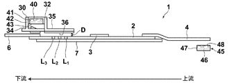
- FIG. 1 is a schematic perspective view of an immunochromatography kit 100 according to an embodiment of the present invention
- FIG. 2 is an exploded schematic perspective view of the immunochromatography kit 100 of FIG.
- the immunochromatographic kit 100 of this embodiment includes a test strip 1 that develops a sample solution and includes an insoluble carrier 2 having a test region of a test substance, and a detection signal in the test region.
- the housing case 9 is disposed between the lower case 20 having the accommodating portion 21 in which the test strip 1 is disposed, the upper case 10 joined to the lower case 20 at the periphery, and the upper case 10 and the lower case 20.
- the intermediate member 30 is provided.
- the upper case 10 side is defined as the upper side
- the lower case 20 side is defined as the lower side.
- the intermediate member 30 has a pot accommodating portion 32 having an amplification solution filling hole for receiving the first pot 40 and dropping the first amplification solution 41 on the insoluble carrier 2 on the bottom surface. Further, a protruding breakage portion 34 for breaking the sheet member 43 is provided at a position facing the sheet member 43 of the first pot 40 in the pot accommodating portion 32.
- the first pot 40 is arranged above the pot accommodating portion 32 so that the surface having the sheet member 43 is the lower surface, and the bottom surface of the pot accommodating portion 32 facing the sheet member 43. Is provided with a breaking portion 34 (see FIG. 3).
- a flow path forming portion 35 extending downstream from the bottom surface of the pot housing portion 32 of the intermediate member 30 is provided.
- the flow path forming unit 35 is arranged in alignment with the upper positions of the inspection region L 1 , the confirmation region L 2, and the amplification index region L 3 , and is a transparent material in order to make these regions L 1 to L 3 visible It is formed with.
- the upper case 10 is deformed to the first pot 40 side by applying a pressing force from the outside to a portion facing the first pot 40, and the sheet member 43 of the first pot 40 is moved to the intermediate member 30.
- the first convex deformation part 12 to be broken by the breaking part 34 is provided.
- the upper case 10 is deformed to the second pot 45 side by applying a pressing force from the outside to a portion facing the second pot 45, and the sheet member 48 of the second pot 45 is broken.
- Two convex deformation portions 14 are provided.
- the upper case 10 is provided with an opening 16 for dropping a sample droplet, from which the sample liquid is dropped onto the label holding pad 3 of the test strip 1.
- the upper case 10 includes an observation window 18 for visually recognizing the three regions L 1 to L 3 at a position corresponding to the flow path forming portion 35 of the intermediate member 30.
- the lower case 20 includes an insoluble carrier accommodating portion 21 on which the insoluble carrier 2 is placed and an absorbent pad accommodating portion 22 on which the absorbent pad 6 is placed on the downstream side as accommodating portions where the test strip 1 is disposed. Is provided.
- a second pot accommodating portion 24 in which the second pot 45 is accommodated is provided on the upstream side of the insoluble carrier accommodating portion 21.
- FIG. 3 is a schematic cross-sectional view showing the positional relationship between the test strip 1, the intermediate member 30, and the two pots 40 and 45.
- the test strip 1 includes an insoluble carrier 2 on which a sample solution is developed, and a labeling substance modified with a first substance that can bind to a test substance fixed on the insoluble carrier 2.
- the liquid feeding pad 4 for feeding the second amplification solution 46 arranged in contact with one end of the insoluble carrier 2 to the insoluble carrier 2, and the other end of the insoluble carrier 2
- the absorption pad 6 is provided.
- the insoluble carrier 2 is fixed and supported on the back adhesive sheet 7.
- the insoluble carrier 2 includes a test region L 1 containing a second substance that binds to the test substance and a confirmation region containing a substance that can bind to the first substance between the label holding pad 3 and the absorption pad 6.
- L 2 and an amplification index region L 3 containing a substance that reacts with the second amplification solution are sequentially provided from the label holding pad 3 side.
- the insoluble carrier 2 in which the examination region L 1 , the confirmation region L 2 and the amplification index region L 3 are formed may be referred to as a chromatographic carrier.
- the liquid-feeding pad 4 side is defined as upstream, and the absorption pad 6 side is defined as downstream.
- the intermediate member 30 is located in the upper part on the downstream end side of the test strip 1, and the first pot 40 is disposed in the pot accommodating portion 32 of the intermediate member 30 with the sheet member 43 facing down.
- the second pot 45 is accommodated below the upstream end of the test strip 1 of the lower case 20 with the sheet member 48 facing upward.
- a gap (clearance) D is formed between the back surface 36 of the flow path forming portion 35 of the intermediate member 30 and the insoluble carrier 2 of the test strip 1.
- This gap D is preferably in the range of 0.01 mm to 1 mm. If it is 0.01 mm or more, the amplification solution can be sufficiently infiltrated, and if it is 1 mm or less, the capillary force is exhibited, and the first amplification solution 41 uniformly fills the gap between the insoluble carrier 2 and the intermediate member 30. Is possible.
- the first pot 40 in which the first amplification liquid 41 is sealed for example, a container 42 having an opening on one surface made of a resin material is filled with the first amplification liquid 41, and the opening of the container 42 can be broken.
- the sheet member 43 is covered and sealed.
- the second pot 45 in which the second amplification liquid 46 is sealed the second amplification liquid 46 is filled in a container 47 having an opening on one surface made of, for example, a resin material, and the opening of the container 47 is opened. Covered and sealed by a breakable sheet member 48.
- a laminate film such as an aluminum foil or an aluminum laminated sheet is preferably used.
- the break means a state in which it is not regenerated after being broken.
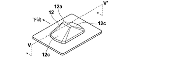
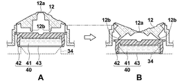
- FIG. 4 is a perspective view showing the first convex deformed portion 12
- FIG. 5 is a sectional view taken along the line VV ′ of FIG. 4, and FIG. Before the deformation of FIG. 5B, FIG. 5B shows the state after the deformation, and shows the positional relationship with the first pot 40.
- the first convex deformation portion 12 is configured to move the first pot 40 to a position where the sheet member 43 is broken by the breaking portion 34 of the intermediate member 30 by applying a pressing force. Specifically, the first convex deformation portion 12 is configured to be pushed downward by being pressed with a finger or the like, and the first convex deformation portion 12 is convex downward. In such a manner (when viewed from the outside, in a concave shape), the first pot is moved to a position where the sheet member 43 of the first pot 40 is broken by the breaking portion 34 in the pot housing portion 32 of the intermediate member 30. 40 is moved toward the breaking portion 34.
- the first amplification liquid 41 is dropped on the upper part of the insoluble carrier 2 from the amplification liquid filling hole provided in the bottom surface of the pot housing portion 32 of the intermediate member 30, and the inspection region L 1 , the confirmation region L 2 on the insoluble carrier, and amplification index regions L 3 it is possible to supply a first amplification solution 41.
- the first amplification solution 41 dropped from the amplification solution filling hole to the upper portion of the insoluble carrier 2 is filled in the gap between the intermediate member 30 and the insoluble carrier 2 and passes through the gap. 1 , supplied above the confirmation region L 2 and the amplification indicator region L 3 and gradually permeates the insoluble carrier 2.
- the first convex deformation portion 12 includes two projecting portions 12 b erected toward the first pot 40 at a position facing the first pot 40.
- the two protrusion portions 12b are in contact with the first pot 40 to move the first pot 40.
- the first convex deformed portion 12 has a centrally symmetric mountain shape, the two protrusions 12b are arranged symmetrically with respect to the mountain-shaped top 12a, and a slope sandwiching the top 12a. They are formed independently of each other below (rear surface) 12c.
- the two projecting portions 12b are positioned symmetrically with respect to the center of the contact surface of the first pot 40.
- the upper case 10 is formed.
- rupture part 34 of the intermediate member 30 is located under the sheet
- the interval between the two protrusions 12b is widened, and the tips of the two protrusions 12b are the contact surfaces of the first pot 40 with each other. It will be located in the edge part side rather than the half of the distance from the center to the edge part.
- the two protrusions 12b are provided independently, and there is a gap between the protrusions 12b (the back surface of the top 12a), and the convex deformation part 12 is formed of a flexible material. As a result, the first pot 40 is pushed down while greatly expanding the gap between the two protrusions 12b.
- the shape and arrangement of the protrusions 12b are not limited to the above-described forms.
- the two protrusions 12b are more than half the distance from the center to the end of the contact surface of the first pot 40. You may be provided in the position used as the side.
- the 1st convex deformation part 12 which moves the 1st pot 40, since there are two projection parts 12b, since the 1st pot 40 can be pushed equally in two places, the 1st The pot 40 can be moved in parallel.
- the first convex deformed portion 12 is easily deformed by pressing with a finger or the like, and the first convex deformed portion 12 becomes convex downward (concave shape). It is preferable that the concave shape does not return after this pressing and the first pot 40 can be kept pressed.
- the first convex deformation portion 12 is configured to press the top 12a, it can be similarly deformed by the elasticity of the convex deformation portion 12 by pressing a mountain-shaped slope.
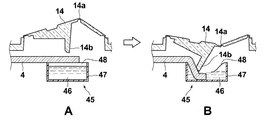
- FIG. 6 is a perspective view showing the second convex deformation portion 14
- FIG. 7 is a sectional view taken along the line VII-VII ′ of FIG. 6, and FIG.
- FIG. 7B shows the state after the deformation, and also shows the positional relationship with the second pot 45.
- the second convex deformation portion 14 is to break the sheet member 48 of the second pot 45 when a pressing force is applied.
- transformation part 14 is equipped with the one projection part 14b erected toward the 2nd pot 45 in the position facing the 2nd pot 45.
- a liquid feeding pad 4 of the test strip 1 is disposed between the second pot 45 and the second pot 45.
- a pressing force is applied to the second convex deformed portion 14 to project toward the second pot 45, that is, deform into a concave shape when viewed from the outside, and the projecting portion 14b is fed as shown in FIG. Abutting on the surface of the liquid pad 4, the sheet member 48 of the second pot 45 is pierced, and the liquid-feeding pad 4 is pushed into the second pot 45.
- the second convex deformation portion 14 has a mountain shape having a peak 14a on the slightly upstream side in a cross section along the upstream and downstream directions. Is inclined toward the downstream side to break through the sheet member 48.
- the liquid-feeding pad 4 is immersed in the amplification liquid 46 in the second pot 45, and the second amplification liquid 46 can penetrate into the liquid-feeding pad 4 by capillary action and be supplied to the insoluble carrier 2. It becomes.
- the second convex deformation portion 14 is also easily deformed into a concave shape by pressing with a finger or the like. It is preferable that the concave shape does not return after the pressing, and the liquid feeding pad 4 can be maintained in a state of being pushed into the second pot 45.
- the present invention realizes highly sensitive analysis by supplying the amplification liquid by deforming the first and second convex deformation parts without using a device connected to a power source. Is assumed to be deformed by hand. Accordingly, it is preferable that the amplification solution is designed not to accidentally leak to the outside, and the first and second convex deformation portions 12 and 14 provided in the upper case 10 are spaced from other portions of the upper case 10. It is preferable that they are integrally formed. It is preferable that the convex deformation parts 12 and 14 are made of a stretchable material and are joined to other parts of the upper case 10 in a sealed state.
- the first and second convex deformation portions 12 and 14 of the upper case 10 and the other portions may be separately manufactured and then joined to each other, but the first and second convex deformations may be used. It is preferable that the parts 12 and 14 are part of the upper case 10 and are integrally molded by injection molding as a single continuous member with no joints in the middle.
- the flexural modulus of the material constituting the convex deformation portions 12 and 14 is preferably 50 MPa or more and 350 MPa or less, and more preferably 70 MPa or more and 150 MPa or less.
- the liquid may leak from the gap, so that the fitting portion of the upper case 10 and the lower case 20 is also sealed. It is preferable that they are adhered.
- an adhesion method between the upper case 10 and the lower case 20 it is preferable to use an ultrasonic welding method. In general, ultrasonic welding is known to be difficult to weld unless the material to be welded is the same material.
- the combination of the upper case / lower case is polyethylene / polyethylene, polypropylene / polypropylene or ABS (acrylonitrile-butadiene-). Styrene copolymer) / ABS is good.
- the convex deformation parts 12 and 14 are formed integrally with the upper case 10, it is necessary that the material constituting the upper case 10 is flexible.
- the lower case 20 is preferably rigid to fix the test strip 1 and the second pot 45.
- the flexural modulus of the material constituting the upper case 10 is preferably 50 MPa or more and 350 MPa or less, and more preferably 70 MPa or more and 150 MPa or less.
- the bending elastic modulus of the material constituting the lower case 20 is preferably 500 MPa to 900 MPa, and particularly preferably 650 MPa to 750 MPa.
- the flexural modulus is a value calculated from equation (1) as follows in an environment at a temperature of 20 ° C. according to the measurement method of the ISO 178 standard.
- a plate-like test piece having a width b (mm) and a thickness h (mm) is prepared for the material for measuring the flexural modulus, and the test piece is supported by two fulcrums with a distance between the fulcrums of L (mm).
- a load of F (N) is applied to the center between the fulcrums, and the amount of deflection (mm) in the applied direction is measured.
- a deflection-load curve is created with the deflection S (mm) on the horizontal axis and the load F (N) on the vertical axis.
- the combination of the upper case / lower case is most preferably a polypropylene / polypropylene combination with a softener.
- the softening agent used for the polypropylene containing the softening agent is preferably an olefin-based elastomer, and the concentration of the olefin-based elastomer with respect to the polypropylene is preferably 20% by mass or more and 60% by mass or less, and particularly preferably 40% by mass or more and 55% by mass or less.
- Specific examples of the softening agent include Tough Selenium (registered trademark) manufactured by Sumitomo Chemical Co., Ltd.
- the immunochromatography kit of the present invention only needs to have two or more convex deformation parts.
- the convex deformation is accordingly performed. Three or more parts may be provided.
- the insoluble carrier 2 for example, a nitrocellulose membrane can be used.
- the back pressure-sensitive adhesive sheet 7 to which the insoluble carrier 2 is fixed is a sheet-like substrate whose surface to which the insoluble carrier 2 is attached is an adhesive surface.
- the label holding pad 3 is fixed to the central portion in the longitudinal direction of the insoluble carrier 2.
- a gold colloid EM.GC50, manufactured by BBI
- the surface of the labeling substance can be modified with a substance that binds to the test substance to form a conjugate with the test substance.
- the labeling substance is not limited to the above, and metal sulfides that can be used in ordinary chromatographic methods, colored particles that are used in immunoaggregation reactions, and the like can be used, and metal colloids are particularly preferable.
- metal colloids include gold colloids, silver colloids, platinum colloids, iron colloids, aluminum hydroxide colloids, and composite colloids thereof. In particular, at appropriate particle sizes, gold colloids are red and silver colloids are yellow. Of these, gold colloid is most preferable.
- test strip 1 is positioned such that the position of the sample droplet opening 16 in the upper case 10 and the label holding pad 3 coincide.
- Inspection area L 1 comprises a second substance that binds to the test substance is a labeling substance complementary region labeling substance bound to the test substance is supplemented via the analyte.
- a labeling substance complementary region labeling substance bound to the test substance is supplemented via the analyte.
- an anti-influenza A monoclonal antibody (Anti-Influenza A SPTN-5 7307, manufactured by Medix Biochemica) is formed into a line by physical adsorption. aspect which constitutes the examination region L 1 by antibody immobilization line being immobilized is preferred.
- This examination region L 1 and a test substance when complex labeling substance is bound through the first material reaches the second substance and a test substance to bind specifically, the test substance and the first material
- the labeling substance will be supplemented via this.
- the labeling substance does not constitute a complex of analyte passes through without being trapped in the examination region L 1.
- Confirmation area L 2 comprises a substance bound to the first substance, it is deployed insoluble carrier 2 medium with the sample liquid from the label holding pad 3, through labeling substance that has passed through the examination region L 1 is a first material This is an area for confirming the completion of the development of the sample liquid.
- a test substance for example, anti-mouse IgG antibody (anti-mouse IgG (H + L), rabbit F (ab ′) 2, product number 566-70621, Jun Wako)
- An embodiment in which Yakuhin Kogyo Co., Ltd.) is immobilized in a line by physical adsorption is preferred.
- Amplification index regions L 3 comprises a material that reacts with the second amplification solution 46, by color or color by reacting with a second amplification fluid 46 is changed, the second amplification fluid 46 is expanded to the area This is a region that indicates that the first amplification liquid 41 is dropped.
- a mixed aqueous solution of an aqueous iron nitrate solution and citric acid (manufactured by Wako Pure Chemical Industries, Ltd., 038-06925) is used as the second amplification solution, Bromocresol Green (Wako Pure Chemical Industries, Ltd.) ) Ltd.) is a mode to configure the amplification index regions L 3 by immobilized chromogenic reagent immobilization line in a line shape is preferred.
- region L 3 changes from green to orange. This discoloration can be captured as an indicator that the inspection region L 1 and the confirmation region L 2 are sufficiently filled with the second amplification liquid 46.
- a method of amplifying a signal of a metal-based labeling substance such as a metal colloid
- silver ions and a reducing agent for silver ions are brought into contact with the labeling substance, and silver ions are reduced by the reducing agent to generate silver particles.
- a method in which silver particles are deposited on a labeling substance using the labeling substance as a nucleus to amplify a signal from the labeling substance hereinafter referred to as silver amplification.
- a solution containing silver ions may be used as the first amplification solution 41
- a reducing agent solution containing a reducing agent for silver ions may be used as the second amplification solution 46.
- the solution containing silver ions used as the first amplification solution 41 is preferably a solution in which a silver ion-containing compound is dissolved in a solvent.
- a silver ion-containing compound an organic silver salt, an inorganic silver salt, or a silver complex can be used.
- it is an inorganic silver salt or a silver complex.
- a silver ion-containing compound having high solubility in a solvent such as water can be used, and examples thereof include silver nitrate, silver acetate, silver lactate, silver butyrate, and silver thiosulfate. Particularly preferred is silver nitrate.
- the silver complex is preferably a silver complex coordinated to a ligand having a water-soluble group such as a hydroxyl group or a sulfone group, and examples thereof include hydroxythioether silver.
- the reducing agent used in the reducing agent solution containing a reducing agent capable of reducing silver ions used as the second amplification solution 46 is inorganic or organic as long as it can reduce silver ions to silver. Any material or mixture thereof may be used.
- Preferred examples of the inorganic reducing agent include reducible metal salts and reducible metal complex salts whose valence can be changed by metal ions such as Fe 2+ , V 2+ and Ti 3+ .
- a complex of Fe 3+ which is an oxide can be formed using citric acid or EDTA (ethylenediaminetetraacetic acid), and can be rendered harmless.
- citric acid or EDTA ethylenediaminetetraacetic acid
- developing agents used in wet silver halide photographic materials for example, methyl gallate, hydroquinone, substituted hydroquinone, 3-pyrazolidones, p-aminophenols, p-phenylenediamines, hindered phenols, amidoximes
- Azines for example, catechols, pyrogallols, ascorbic acid (or derivatives thereof, and leuco dyes)
- other materials apparent to those skilled in the art such as those described in US Pat. No. 6,020,117 Can also be used.
- an ascorbic acid reducing agent is also preferable.
- useful ascorbic acid reducing agents include ascorbic acid analogs, isomers and derivatives thereof, such as D- or L-ascorbic acid and sugar derivatives thereof (eg ⁇ -lactoascorbic acid, glucoascorbic acid, fucoscorbic acid).
- Glucoheptascorbic acid, maltoascorbic acid sodium salt of ascorbic acid, potassium salt of ascorbic acid, isoascorbic acid (or L-erythroascorbic acid), salts thereof (eg alkali metal salts, ammonium salts or the art) Salt), enediol type ascorbic acid, enaminol type ascorbic acid, thioenol type ascorbic acid and the like, and particularly D, L or D, L-ascorbic acid (and Its alkali metal salt) Ku is isoascorbic acid (or alkali metal salts) is preferably, sodium salts are preferred salts. A mixture of these reducing agents can be used as necessary.
- the first convex deformation portion 12 moves the first pot 40 toward the fracture portion 34 provided in the intermediate member 30, but the first convex deformation
- the part 12 should just be the structure which can break the sheet
- the configuration of the first pot 40 and the housing portion 32 that houses the first pot 40 is not limited to the configuration of the present embodiment.
- the first convex member may have a single protrusion having the same shape as the second convex deformed portion of the above embodiment.
- a convex deformation part having the same shape as the second convex part deformation part may also be used as the first convex deformation part for moving the first pot 40.
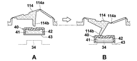
- FIG. 8 is a cut end view similar to FIG. 7 showing a form in which a deformable portion 114 having the same shape as the second convex deformable portion is used to move the first pot 40.
- the first pot 40 is disposed below the protrusion 114b of the convex deformation portion 114.
- a broken portion 34 of the intermediate member 30 is located below the first pot 40.
- the breaking portion 34 breaks through the sheet member 43 of the first pot 40, and the first amplification solution 41 enclosed in the first pot 40 flows out of the first pot and is supplied to the test strip 1.
- the in this way, the pot can be moved even if there is only one protrusion provided on the convex deformation portion 114.
- the immunochromatography kit of the present invention includes a pot containing a sample extract containing an auxiliary chemical that assists the extraction of the sample, a pot containing a sample diluent, a desiccant or an oxygen scavenger that helps preserve the kit, It may include package inserts such as instruction manuals and a set of equipment necessary for inspection of a sample collection instrument such as a cotton swab or a part thereof.
- An immunochromatographic inspection method using the immunochromatographic kit 100 will be briefly described.
- a sample solution is dropped onto the label holding pad 3 from the opening 16 for dropping the sample droplet.
- the test substance and the first substance are bonded to each other in the label holding pad 3 so that the test substance and the label substance through the first substance are bonded.
- a complex is formed, and this complex is developed together with the sample solution toward the absorption pad 6 side by capillary action by the suction force of the absorption pad 6.
- the second convex deformation portion 14 is pressed down to displace the liquid-feeding pad 4 to break the sheet member 48 of the second pot 45, and the liquid-feeding pad 4
- the second amplification solution 46 is immersed in the second amplification solution 46 and sent to the insoluble carrier 2.
- the timing of pressing the second convex deformation portion 14 is preferably within 30 seconds from the time when the sample liquid is dropped, and particularly preferably immediately after the dropping of the sample liquid.
- Complex reaches the examination region L 1 is captured combined with a second material of the examination region L 1.
- the first materials not bound to the analyte reaches the verification area L 2 passes through the examination region L 1, binds to the captured as a substance that binds to the first substance confirmation area L 2 .
- Second amplification fluid 46 reaches the examination region L 1, amplification index regions L 3 through the check region L 2. At this time, when the amplification index region L 3 changes color, it is possible to visually recognize the arrival of the second amplification liquid 46 to the amplification index region L 3 . After confirming the discoloration of the amplification index region L 3 , the first convex deformation portion 12 is pressed to supply the first amplification solution 41 onto the insoluble carrier 2.
- the completion of the reaction is awaited, and the color development in the inspection region L 1 and the confirmation region L 2 is confirmed from the observation window 18.
- the color of the inspection area L 1 can ascertain the level of presence and concentration of the analyte, that test that measures the analyte by coloring the confirmation area L 2 To verify that successful it can.
- Color in the examination region L 1 and confirmation area L 2 are those obtained by amplifying the signal of the label, it is possible to realize a high-sensitivity examination.
- the immunochromatography kits of Examples and Comparative Examples are immunochromatography kits for detecting influenza virus antigens for detecting influenza virus antigens as test substances.
- the supernatant liquid was removed leaving 1 mL at the bottom of the container, and the gold colloid contained in the 1 mL liquid remaining at the bottom of the container was redispersed by an ultrasonic cleaner. Then, it is dispersed in 20 mL of colloidal gold stock solution (20 mmol / L Tris-HCl (Tris-HCl) buffer (pH 8.2), 0.05% PEG (Mw. 20000), 150 mmol / L NaCl, 1% BSA). Centrifugation was again performed under the same conditions using the same centrifuge, and the supernatant was removed. After ultrasonic dispersion, the solution was dispersed in a gold colloid preservation solution to obtain an antibody-modified gold colloid (50 nm) solution.
- colloidal gold stock solution (20 mmol / L Tris-HCl (Tris-HCl) buffer (pH 8.2), 0.05% PEG (Mw. 20000), 150 mmol / L NaCl, 1% BSA). Centr
- This coating solution is uniformly applied at 0.8 mL per glass fiber pad (Glass Fiber Conjugate Pad, manufactured by Millipore) cut to 12 mm x 300 mm, and dried for 24 hours under reduced pressure to retain influenza A antibody-modified gold colloid I got a pad.
- Glass Fiber Conjugate Pad manufactured by Millipore
- Anti-influenza A monoclonal antibody (Anti-Influenza A SPTN-5 7307, manufactured by Medix Biochemica) prepared at a position 15 mm from the downstream side of the 60-mm short side of the nitrocellulose membrane at 1.5 mg / mL ) The solution was applied in a line to form an inspection area. Furthermore, an anti-mouse IgG antibody (anti-mouse IgG (H + L), rabbit F (ab ′) 2, part number 566 ⁇ ) prepared to be 0.2 mg / mL at a position 11 mm from the downstream side of the short side of 60 mm. 70621 (manufactured by Wako Pure Chemical Industries, Ltd.) was applied in a line to form a confirmation region.
- Bromocresol Green (manufactured by Wako Pure Chemical Industries, Ltd.) prepared at 30 mmol / L was applied in a line at a position 9 mm from the downstream side of the short side of 60 mm to form an amplification index region.
- the nitrocellulose membrane was dried at 50 ° C. for 30 minutes with a hot air dryer.
- a blocking solution 50 mmol / L borate buffer (pH 8.5) containing 0.5% by mass of casein (derived from milk, product number 030-01505, manufactured by Wako Pure Chemical Industries, Ltd.)
- the nitrose membrane dried as described above was immersed in a 500 mL bat and allowed to stand for 30 minutes.
- nitrocellulose membrane was taken out, and a cleaning / stabilizing solution prepared in another vat (50 mmol / L Tris-HCl (pH 7.5) buffer containing 0.5 mass% sucrose and 0.05 mass% sodium cholate)
- a cleaning / stabilizing solution prepared in another vat 50 mmol / L Tris-HCl (pH 7.5) buffer containing 0.5 mass% sucrose and 0.05 mass% sodium cholate
- the nitrocellulose membrane was immersed in 500 mL and allowed to stand for 30 minutes. Thereafter, the nitrocellulose membrane was taken out of the liquid and dried in an environment at 25 ° C. for 24 hours.
- a test region in which the portion to which the anti-influenza A antibody is immobilized contains a second substance that binds to the test substance, and a confirmation region in which the part to which the anti-mouse IgG antibody is immobilized contains a substance that can bind to the first substance ,
- a liquid-feeding pad (glass fiber pad (Glass Fiber Conjugate Pad, manufactured by Millipore) cut to 25 mm ⁇ 300 mm) was attached to the upstream side of the chromatographic carrier so that the liquid-feeding pad and the chromatographic carrier overlapped by 7 mm. .
- the member thus produced was cut with a guillotine cutter (CM4000, manufactured by NIPPN Technocluster Co., Ltd.) so that the width was 5 mm parallel to the direction perpendicular to the long side of 300 mm, and 60 test strips ( However, the absorbent pad was not included.
- nitric acid (10 wt%) 5.9 mL, dodecylamine (Wako Pure Chemical Industries Co., Ltd., 123-00246) 0.1 g, surfactant C 12 H 25 -C 6 H 4 -
- 0.1 g of O— (CH 2 CH 2 O) 50 H was previously dissolved in 47.6 g of water was mixed, and this was used as a silver ion solution as a first amplification solution sealed in the first pot. .
- the upper case was produced by injection molding using polypropylene containing 50% by mass of Tough Selenium (registered trademark), which is an olefin elastomer manufactured by Sumitomo Chemical Co., Ltd., as a material.
- the upper case 10 includes two deformable portions (a first convex deformation portion and a second convex deformation portion), and these two deformation portions do not have a part that separates from the upper case 10, It was produced by injection molding as part of the upper case 10 at all boundaries.
- the first convex deformation portion 12 shown in FIGS. 1 and 2 and the like has two protrusions, and the second convex deformation portion 14 has one protrusion. It was set as the structure which has.
- the upper case of Example 2 was configured to include two convex deformed portions having only one protrusion having the same shape as the second convex deformed portion 14 shown in FIGS. That is, as shown in FIG. 8, the upper case of the second embodiment includes the first convex deformation portion 114 above the first pot 40 and the second convex shape above the second pot 45.
- the deformation portion 14 is provided.
- the flexural modulus of the material of the upper case and the lower case was 90 (MPa) and 700 (MPa), respectively.
- Table 1 shows the result of the same test repeated five times for each example.
- the supply amount of the silver ion solution was determined according to the following criteria.
- A: 40 ⁇ L or more B: 20 ⁇ L or more and less than 40 ⁇ L C: less than 20 ⁇ L ⁇ OD was determined according to the following criteria.
- Amplification can be performed accurately and sufficient analysis is possible.
- both the immunochromatographic kits of Example 1 and Example 2 are within the allowable ranges for both the supply amount of the first amplification solution and the value of ⁇ OD and can be sufficiently amplified. .
- the first pot 40 in which there are two projections of the first convex member that pushes the first pot 40, the first pot 40 can be pushed with a flat surface, and the silver ion solution is stably more than the target amount Thus, the amplification reaction could be stably carried out stably.
- the variation coefficient CV of ⁇ OD in Example 1 was as low as 10%, and that the shape having two protrusions could be measured with high accuracy.
- the measurement result of ⁇ OD in the table is consistent with the evaluation result when visually evaluated, and the solution necessary for increasing the sensitivity of the amplification solution, etc. without using a device that uses a power source such as an analyzer.
- An immunochromatography kit capable of supplying
Abstract
Le problème à résoudre dans le cadre de la présente invention consiste à fournir un kit d'immunochromatographie avec lequel on réalise des mesures de sensibilité élevée sans avoir besoin d'un dispositif d'analyse dédié. La solution consiste en un boîtier de logement (9) destiné à renfermer une bandelette réactive (1), un premier pot (40) dans lequel un premier liquide d'amplification (41) est maintenu de façon étanche, et un second pot (45) dans lequel un second fluide d'amplification (46) est maintenu de façon étanche, ledit boîtier de logement étant pourvu d'un boîtier inférieur (20), d'un boîtier supérieur (10) et d'un élément intermédiaire (30) positionné entre le boîtier inférieur (20) et le boîtier supérieur (10). Le boîtier supérieur (10) est pourvu d'une première partie de déformation convexe (12) dans une partie faisant face au premier pot (40), et d'une seconde partie de déformation convexe (14) dans une partie faisant face au second pot (45). La première partie de déformation convexe (12) est configurée de sorte à se déformer vers le premier pot (40) suite à une force de pression qui est appliquée depuis l'extérieur, et un élément de feuille (43) du premier pot (40) est cassé par une partie de rupture (34) de l'élément intermédiaire (30). La seconde partie de déformation convexe (14) est configurée de sorte à se déformer vers le second pot (45) et rompre un élément de feuille (48) du second pot (45) grâce à une force de pression qui est appliquée depuis l'extérieur.
Priority Applications (4)
| Application Number | Priority Date | Filing Date | Title |
|---|---|---|---|
| EP16875131.1A EP3392655B1 (fr) | 2015-12-18 | 2016-12-16 | Kit d'immunochromatographie |
| CN201680073351.2A CN108369228B (zh) | 2015-12-18 | 2016-12-16 | 免疫层析试剂盒 |
| JP2017556337A JP6570652B2 (ja) | 2015-12-18 | 2016-12-16 | イムノクロマトグラフキット |
| US16/008,050 US10520497B2 (en) | 2015-12-18 | 2018-06-14 | Immunochromatographic kit |
Applications Claiming Priority (2)
| Application Number | Priority Date | Filing Date | Title |
|---|---|---|---|
| JP2015247351 | 2015-12-18 | ||
| JP2015-247351 | 2015-12-18 |
Related Child Applications (1)
| Application Number | Title | Priority Date | Filing Date |
|---|---|---|---|
| US16/008,050 Continuation US10520497B2 (en) | 2015-12-18 | 2018-06-14 | Immunochromatographic kit |
Publications (1)
| Publication Number | Publication Date |
|---|---|
| WO2017104143A1 true WO2017104143A1 (fr) | 2017-06-22 |
Family
ID=59055947
Family Applications (1)
| Application Number | Title | Priority Date | Filing Date |
|---|---|---|---|
| PCT/JP2016/005163 WO2017104143A1 (fr) | 2015-12-18 | 2016-12-16 | Kit d'immunochromatographie |
Country Status (5)
| Country | Link |
|---|---|
| US (1) | US10520497B2 (fr) |
| EP (1) | EP3392655B1 (fr) |
| JP (1) | JP6570652B2 (fr) |
| CN (1) | CN108369228B (fr) |
| WO (1) | WO2017104143A1 (fr) |
Cited By (16)
| Publication number | Priority date | Publication date | Assignee | Title |
|---|---|---|---|---|
| WO2019116527A1 (fr) * | 2017-12-15 | 2019-06-20 | デンカ生研株式会社 | Kit d'essai |
| WO2019124532A1 (fr) * | 2017-12-22 | 2019-06-27 | 株式会社 三和化学研究所 | Dispositif d'immunochromatographie |
| WO2019131475A1 (fr) * | 2017-12-28 | 2019-07-04 | 株式会社Icst | Dispositif d'essai et procédé d'essai |
| WO2020045524A1 (fr) * | 2018-08-29 | 2020-03-05 | 富士フイルム株式会社 | Kit de chromatographie et méthode de chromatographie |
| TWI688759B (zh) * | 2019-04-02 | 2020-03-21 | 邦睿生技股份有限公司 | 檢驗試片裝置 |
| WO2021152965A1 (fr) * | 2020-01-31 | 2021-08-05 | 富士フイルム株式会社 | Immunochromatographie |
| EP3845903A4 (fr) * | 2018-08-31 | 2021-11-24 | FUJIFILM Corporation | Kit d'immunochromatographie et méthode de détection de mycobacterium tuberculosis |
| WO2022202380A1 (fr) | 2021-03-26 | 2022-09-29 | 富士フイルム株式会社 | Cartouche d'inspection |
| WO2022202262A1 (fr) | 2021-03-24 | 2022-09-29 | 富士フイルム株式会社 | Cartouche et appareil de détection immunochromatographique |
| WO2022202379A1 (fr) | 2021-03-26 | 2022-09-29 | 富士フイルム株式会社 | Cartouche d'essai |
| WO2022202263A1 (fr) | 2021-03-24 | 2022-09-29 | 富士フイルム株式会社 | Appareil d'inspection immunochromatographique |
| WO2022202261A1 (fr) | 2021-03-24 | 2022-09-29 | 富士フイルム株式会社 | Dispositif de test immunochromatographique |
| WO2023008128A1 (fr) * | 2021-07-30 | 2023-02-02 | 富士フイルム株式会社 | Cartouche d'essai |
| WO2023053586A1 (fr) * | 2021-09-29 | 2023-04-06 | 富士フイルム株式会社 | Kit d'immunochromatographie et dispositif de test |
| WO2024070698A1 (fr) * | 2022-09-26 | 2024-04-04 | 富士フイルム株式会社 | Cartouche immunochromatographique |
| WO2024070697A1 (fr) * | 2022-09-26 | 2024-04-04 | 富士フイルム株式会社 | Dispositif de test immunochromatographique |
Families Citing this family (4)
| Publication number | Priority date | Publication date | Assignee | Title |
|---|---|---|---|---|
| CN107110858B (zh) * | 2015-01-16 | 2019-03-08 | 富士胶片株式会社 | 免疫层析试剂盒 |
| CN111929442A (zh) * | 2020-08-13 | 2020-11-13 | 北京测尔康生物技术有限公司 | 一种新型冠状病毒抗原和抗体检测试剂盒 |
| WO2022107737A1 (fr) | 2020-11-17 | 2022-05-27 | 富士フイルム株式会社 | KIT ET PROCÉDÉ DE DÉTECTION DE SARS-CoV-2 |
| GB2604367A (en) * | 2021-03-03 | 2022-09-07 | Biotip Ltd | Devices and methods for performing lateral flow tests |
Citations (9)
| Publication number | Priority date | Publication date | Assignee | Title |
|---|---|---|---|---|
| WO1986006488A1 (fr) * | 1985-04-29 | 1986-11-06 | Hichem Diagnostics, Inc., Dba Bural Technologies | Kit pour tests diagnostiques |
| JPH10104236A (ja) * | 1996-09-30 | 1998-04-24 | Fujirebio Inc | マトリックスへの液体供給装置および該装置を有する試験用具 |
| US6020117A (en) | 1998-09-30 | 2000-02-01 | Eastman Kodak Company | Thermally processable imaging element |
| JP2005061910A (ja) | 2003-08-08 | 2005-03-10 | Fujirebio Inc | Hiv抗原抗体測定用免疫測定器具及び測定方法 |
| JP2006524815A (ja) | 2003-04-25 | 2006-11-02 | バイオ ディジット ラボラトリーズ コーポレーション | ポイントオブケア検査用メンブレンストリップバイオセンサーシステム |
| JP2007064829A (ja) * | 2005-08-31 | 2007-03-15 | Fujirebio Inc | 試験用具 |
| JP2010230634A (ja) * | 2009-03-30 | 2010-10-14 | Fujifilm Corp | アッセイ方法およびアッセイ用デバイス |
| JP2011099724A (ja) | 2009-11-05 | 2011-05-19 | Fujifilm Corp | アッセイ用デバイス |
| WO2011111108A1 (fr) * | 2010-03-11 | 2011-09-15 | Dicプラスチック株式会社 | Instrument pour le dosage immunologique lié à une enzyme et dosage immunologique lié à une enzyme |
Family Cites Families (2)
| Publication number | Priority date | Publication date | Assignee | Title |
|---|---|---|---|---|
| US9599623B2 (en) * | 2011-06-09 | 2017-03-21 | Immucor Gti Diagnostics, Inc. | Diagnostic devices, methods and systems for detecting platelet factor 4 (PF4)/heparin antibodies |
| JP5683543B2 (ja) * | 2011-09-29 | 2015-03-11 | 富士フイルム株式会社 | クロマトグラフキット及びクロマトグラフ方法 |
-
2016
- 2016-12-16 WO PCT/JP2016/005163 patent/WO2017104143A1/fr active Application Filing
- 2016-12-16 EP EP16875131.1A patent/EP3392655B1/fr active Active
- 2016-12-16 JP JP2017556337A patent/JP6570652B2/ja active Active
- 2016-12-16 CN CN201680073351.2A patent/CN108369228B/zh active Active
-
2018
- 2018-06-14 US US16/008,050 patent/US10520497B2/en active Active
Patent Citations (9)
| Publication number | Priority date | Publication date | Assignee | Title |
|---|---|---|---|---|
| WO1986006488A1 (fr) * | 1985-04-29 | 1986-11-06 | Hichem Diagnostics, Inc., Dba Bural Technologies | Kit pour tests diagnostiques |
| JPH10104236A (ja) * | 1996-09-30 | 1998-04-24 | Fujirebio Inc | マトリックスへの液体供給装置および該装置を有する試験用具 |
| US6020117A (en) | 1998-09-30 | 2000-02-01 | Eastman Kodak Company | Thermally processable imaging element |
| JP2006524815A (ja) | 2003-04-25 | 2006-11-02 | バイオ ディジット ラボラトリーズ コーポレーション | ポイントオブケア検査用メンブレンストリップバイオセンサーシステム |
| JP2005061910A (ja) | 2003-08-08 | 2005-03-10 | Fujirebio Inc | Hiv抗原抗体測定用免疫測定器具及び測定方法 |
| JP2007064829A (ja) * | 2005-08-31 | 2007-03-15 | Fujirebio Inc | 試験用具 |
| JP2010230634A (ja) * | 2009-03-30 | 2010-10-14 | Fujifilm Corp | アッセイ方法およびアッセイ用デバイス |
| JP2011099724A (ja) | 2009-11-05 | 2011-05-19 | Fujifilm Corp | アッセイ用デバイス |
| WO2011111108A1 (fr) * | 2010-03-11 | 2011-09-15 | Dicプラスチック株式会社 | Instrument pour le dosage immunologique lié à une enzyme et dosage immunologique lié à une enzyme |
Non-Patent Citations (1)
| Title |
|---|
| See also references of EP3392655A4 |
Cited By (28)
| Publication number | Priority date | Publication date | Assignee | Title |
|---|---|---|---|---|
| WO2019116527A1 (fr) * | 2017-12-15 | 2019-06-20 | デンカ生研株式会社 | Kit d'essai |
| JP7241696B2 (ja) | 2017-12-22 | 2023-03-17 | 株式会社三和化学研究所 | イムノクロマトグラフィー装置 |
| CN111480078B (zh) * | 2017-12-22 | 2023-09-29 | 株式会社三和化学研究所 | 免疫层析装置 |
| WO2019124532A1 (fr) * | 2017-12-22 | 2019-06-27 | 株式会社 三和化学研究所 | Dispositif d'immunochromatographie |
| CN111480078A (zh) * | 2017-12-22 | 2020-07-31 | 株式会社三和化学研究所 | 免疫层析装置 |
| JPWO2019124532A1 (ja) * | 2017-12-22 | 2020-12-17 | 株式会社三和化学研究所 | イムノクロマトグラフィー装置 |
| US11619630B2 (en) | 2017-12-22 | 2023-04-04 | Sanwa Kagaku Kenkyusho Co., Ltd. | Immunochromatography device |
| EP3726216A4 (fr) * | 2017-12-28 | 2021-09-15 | Icst Corporation | Dispositif d'essai et procédé d'essai |
| WO2019131475A1 (fr) * | 2017-12-28 | 2019-07-04 | 株式会社Icst | Dispositif d'essai et procédé d'essai |
| JP2019120508A (ja) * | 2017-12-28 | 2019-07-22 | 株式会社Icst | 試験器具および試験方法 |
| EP3845900A4 (fr) * | 2018-08-29 | 2021-10-27 | FUJIFILM Corporation | Kit de chromatographie et méthode de chromatographie |
| JPWO2020045524A1 (ja) * | 2018-08-29 | 2021-08-10 | 富士フイルム株式会社 | クロマトグラフキットおよびクロマトグラフ方法 |
| WO2020045524A1 (fr) * | 2018-08-29 | 2020-03-05 | 富士フイルム株式会社 | Kit de chromatographie et méthode de chromatographie |
| JP7141458B2 (ja) | 2018-08-29 | 2022-09-22 | 富士フイルム株式会社 | クロマトグラフキットおよびクロマトグラフ方法 |
| EP3845903A4 (fr) * | 2018-08-31 | 2021-11-24 | FUJIFILM Corporation | Kit d'immunochromatographie et méthode de détection de mycobacterium tuberculosis |
| TWI688759B (zh) * | 2019-04-02 | 2020-03-21 | 邦睿生技股份有限公司 | 檢驗試片裝置 |
| WO2021152965A1 (fr) * | 2020-01-31 | 2021-08-05 | 富士フイルム株式会社 | Immunochromatographie |
| JPWO2021152965A1 (fr) * | 2020-01-31 | 2021-08-05 | ||
| JP7350100B2 (ja) | 2020-01-31 | 2023-09-25 | 富士フイルム株式会社 | イムノクロマトグラフィー |
| WO2022202262A1 (fr) | 2021-03-24 | 2022-09-29 | 富士フイルム株式会社 | Cartouche et appareil de détection immunochromatographique |
| WO2022202263A1 (fr) | 2021-03-24 | 2022-09-29 | 富士フイルム株式会社 | Appareil d'inspection immunochromatographique |
| WO2022202261A1 (fr) | 2021-03-24 | 2022-09-29 | 富士フイルム株式会社 | Dispositif de test immunochromatographique |
| WO2022202379A1 (fr) | 2021-03-26 | 2022-09-29 | 富士フイルム株式会社 | Cartouche d'essai |
| WO2022202380A1 (fr) | 2021-03-26 | 2022-09-29 | 富士フイルム株式会社 | Cartouche d'inspection |
| WO2023008128A1 (fr) * | 2021-07-30 | 2023-02-02 | 富士フイルム株式会社 | Cartouche d'essai |
| WO2023053586A1 (fr) * | 2021-09-29 | 2023-04-06 | 富士フイルム株式会社 | Kit d'immunochromatographie et dispositif de test |
| WO2024070698A1 (fr) * | 2022-09-26 | 2024-04-04 | 富士フイルム株式会社 | Cartouche immunochromatographique |
| WO2024070697A1 (fr) * | 2022-09-26 | 2024-04-04 | 富士フイルム株式会社 | Dispositif de test immunochromatographique |
Also Published As
| Publication number | Publication date |
|---|---|
| EP3392655A4 (fr) | 2018-10-24 |
| US10520497B2 (en) | 2019-12-31 |
| EP3392655B1 (fr) | 2020-08-19 |
| JPWO2017104143A1 (ja) | 2018-09-27 |
| JP6570652B2 (ja) | 2019-09-04 |
| CN108369228B (zh) | 2020-11-17 |
| EP3392655A1 (fr) | 2018-10-24 |
| US20180292398A1 (en) | 2018-10-11 |
| CN108369228A (zh) | 2018-08-03 |
Similar Documents
| Publication | Publication Date | Title |
|---|---|---|
| JP6570652B2 (ja) | イムノクロマトグラフキット | |
| JP6386095B2 (ja) | イムノクロマトグラフキット | |
| JP2008522169A (ja) | 改善された検査結果有効性を提供するラテラルフロー検査デバイス | |
| JP5276568B2 (ja) | アッセイ用デバイス | |
| JP5430995B2 (ja) | アッセイ方法およびアッセイ用デバイス | |
| WO2010061992A1 (fr) | Procédé d'amplification de signal dans une analyse immunochromatographique et kit immunochromatographique utilisant le procédé | |
| JP7130045B2 (ja) | イムノクロマトグラフキットおよび結核菌の検出方法 | |
| JP6254994B2 (ja) | 検査キット | |
| WO2021065300A1 (fr) | Méthode d'essai immunologique et gabarit de condensation | |
| US20230341398A1 (en) | SARS-CoV-2 DETECTION KIT AND SARS-CoV-2 DETECTION METHOD | |
| WO2020045524A1 (fr) | Kit de chromatographie et méthode de chromatographie | |
| US20230228749A1 (en) | Concentration device, sample solution concentration method, sample solution examination method, and examination kit | |
| US20230228748A1 (en) | Sample solution concentration method and sample solution examination method | |
| US20230251248A1 (en) | Concentration device, sample solution concentration method, sample solution examination method, and examination kit | |
| US11828756B2 (en) | Lateral flow test arrangement suitable for detection of an analyte in saliva | |
| WO2023008128A1 (fr) | Cartouche d'essai | |
| WO2023008129A1 (fr) | Cartouche d'inspection | |
| JPWO2020166698A1 (ja) | イムノクロマト試験片およびそれを用いた測定方法 |
Legal Events
| Date | Code | Title | Description |
|---|---|---|---|
| 121 | Ep: the epo has been informed by wipo that ep was designated in this application |
Ref document number: 16875131 Country of ref document: EP Kind code of ref document: A1 |
|
| DPE1 | Request for preliminary examination filed after expiration of 19th month from priority date (pct application filed from 20040101) | ||
| ENP | Entry into the national phase |
Ref document number: 2017556337 Country of ref document: JP Kind code of ref document: A |
|
| NENP | Non-entry into the national phase |
Ref country code: DE |
|
| WWE | Wipo information: entry into national phase |
Ref document number: 2016875131 Country of ref document: EP |