WO2014148192A1 - Exhaust gas control device of gas engine - Google Patents
Exhaust gas control device of gas engine Download PDFInfo
- Publication number
- WO2014148192A1 WO2014148192A1 PCT/JP2014/054052 JP2014054052W WO2014148192A1 WO 2014148192 A1 WO2014148192 A1 WO 2014148192A1 JP 2014054052 W JP2014054052 W JP 2014054052W WO 2014148192 A1 WO2014148192 A1 WO 2014148192A1
- Authority
- WO
- WIPO (PCT)
- Prior art keywords
- nox
- gas
- engine
- operation mode
- ignition timing
- Prior art date
Links
Images


Classifications
-
- F—MECHANICAL ENGINEERING; LIGHTING; HEATING; WEAPONS; BLASTING
- F02—COMBUSTION ENGINES; HOT-GAS OR COMBUSTION-PRODUCT ENGINE PLANTS
- F02D—CONTROLLING COMBUSTION ENGINES
- F02D37/00—Non-electrical conjoint control of two or more functions of engines, not otherwise provided for
- F02D37/02—Non-electrical conjoint control of two or more functions of engines, not otherwise provided for one of the functions being ignition
-
- F—MECHANICAL ENGINEERING; LIGHTING; HEATING; WEAPONS; BLASTING
- F01—MACHINES OR ENGINES IN GENERAL; ENGINE PLANTS IN GENERAL; STEAM ENGINES
- F01N—GAS-FLOW SILENCERS OR EXHAUST APPARATUS FOR MACHINES OR ENGINES IN GENERAL; GAS-FLOW SILENCERS OR EXHAUST APPARATUS FOR INTERNAL COMBUSTION ENGINES
- F01N3/00—Exhaust or silencing apparatus having means for purifying, rendering innocuous, or otherwise treating exhaust
- F01N3/08—Exhaust or silencing apparatus having means for purifying, rendering innocuous, or otherwise treating exhaust for rendering innocuous
- F01N3/10—Exhaust or silencing apparatus having means for purifying, rendering innocuous, or otherwise treating exhaust for rendering innocuous by thermal or catalytic conversion of noxious components of exhaust
- F01N3/18—Exhaust or silencing apparatus having means for purifying, rendering innocuous, or otherwise treating exhaust for rendering innocuous by thermal or catalytic conversion of noxious components of exhaust characterised by methods of operation; Control
- F01N3/20—Exhaust or silencing apparatus having means for purifying, rendering innocuous, or otherwise treating exhaust for rendering innocuous by thermal or catalytic conversion of noxious components of exhaust characterised by methods of operation; Control specially adapted for catalytic conversion ; Methods of operation or control of catalytic converters
- F01N3/206—Adding periodically or continuously substances to exhaust gases for promoting purification, e.g. catalytic material in liquid form, NOx reducing agents
-
- F—MECHANICAL ENGINEERING; LIGHTING; HEATING; WEAPONS; BLASTING
- F01—MACHINES OR ENGINES IN GENERAL; ENGINE PLANTS IN GENERAL; STEAM ENGINES
- F01N—GAS-FLOW SILENCERS OR EXHAUST APPARATUS FOR MACHINES OR ENGINES IN GENERAL; GAS-FLOW SILENCERS OR EXHAUST APPARATUS FOR INTERNAL COMBUSTION ENGINES
- F01N9/00—Electrical control of exhaust gas treating apparatus
-
- F—MECHANICAL ENGINEERING; LIGHTING; HEATING; WEAPONS; BLASTING
- F02—COMBUSTION ENGINES; HOT-GAS OR COMBUSTION-PRODUCT ENGINE PLANTS
- F02D—CONTROLLING COMBUSTION ENGINES
- F02D19/00—Controlling engines characterised by their use of non-liquid fuels, pluralities of fuels, or non-fuel substances added to the combustible mixtures
- F02D19/02—Controlling engines characterised by their use of non-liquid fuels, pluralities of fuels, or non-fuel substances added to the combustible mixtures peculiar to engines working with gaseous fuels
-
- F—MECHANICAL ENGINEERING; LIGHTING; HEATING; WEAPONS; BLASTING
- F02—COMBUSTION ENGINES; HOT-GAS OR COMBUSTION-PRODUCT ENGINE PLANTS
- F02D—CONTROLLING COMBUSTION ENGINES
- F02D23/00—Controlling engines characterised by their being supercharged
-
- F—MECHANICAL ENGINEERING; LIGHTING; HEATING; WEAPONS; BLASTING
- F02—COMBUSTION ENGINES; HOT-GAS OR COMBUSTION-PRODUCT ENGINE PLANTS
- F02D—CONTROLLING COMBUSTION ENGINES
- F02D41/00—Electrical control of supply of combustible mixture or its constituents
- F02D41/0025—Controlling engines characterised by use of non-liquid fuels, pluralities of fuels, or non-fuel substances added to the combustible mixtures
- F02D41/0027—Controlling engines characterised by use of non-liquid fuels, pluralities of fuels, or non-fuel substances added to the combustible mixtures the fuel being gaseous
-
- F—MECHANICAL ENGINEERING; LIGHTING; HEATING; WEAPONS; BLASTING
- F02—COMBUSTION ENGINES; HOT-GAS OR COMBUSTION-PRODUCT ENGINE PLANTS
- F02D—CONTROLLING COMBUSTION ENGINES
- F02D41/00—Electrical control of supply of combustible mixture or its constituents
- F02D41/02—Circuit arrangements for generating control signals
- F02D41/021—Introducing corrections for particular conditions exterior to the engine
- F02D41/0235—Introducing corrections for particular conditions exterior to the engine in relation with the state of the exhaust gas treating apparatus
-
- F—MECHANICAL ENGINEERING; LIGHTING; HEATING; WEAPONS; BLASTING
- F02—COMBUSTION ENGINES; HOT-GAS OR COMBUSTION-PRODUCT ENGINE PLANTS
- F02M—SUPPLYING COMBUSTION ENGINES IN GENERAL WITH COMBUSTIBLE MIXTURES OR CONSTITUENTS THEREOF
- F02M21/00—Apparatus for supplying engines with non-liquid fuels, e.g. gaseous fuels stored in liquid form
- F02M21/02—Apparatus for supplying engines with non-liquid fuels, e.g. gaseous fuels stored in liquid form for gaseous fuels
-
- F—MECHANICAL ENGINEERING; LIGHTING; HEATING; WEAPONS; BLASTING
- F02—COMBUSTION ENGINES; HOT-GAS OR COMBUSTION-PRODUCT ENGINE PLANTS
- F02P—IGNITION, OTHER THAN COMPRESSION IGNITION, FOR INTERNAL-COMBUSTION ENGINES; TESTING OF IGNITION TIMING IN COMPRESSION-IGNITION ENGINES
- F02P5/00—Advancing or retarding ignition; Control therefor
- F02P5/04—Advancing or retarding ignition; Control therefor automatically, as a function of the working conditions of the engine or vehicle or of the atmospheric conditions
- F02P5/045—Advancing or retarding ignition; Control therefor automatically, as a function of the working conditions of the engine or vehicle or of the atmospheric conditions combined with electronic control of other engine functions, e.g. fuel injection
-
- F—MECHANICAL ENGINEERING; LIGHTING; HEATING; WEAPONS; BLASTING
- F02—COMBUSTION ENGINES; HOT-GAS OR COMBUSTION-PRODUCT ENGINE PLANTS
- F02P—IGNITION, OTHER THAN COMPRESSION IGNITION, FOR INTERNAL-COMBUSTION ENGINES; TESTING OF IGNITION TIMING IN COMPRESSION-IGNITION ENGINES
- F02P5/00—Advancing or retarding ignition; Control therefor
- F02P5/04—Advancing or retarding ignition; Control therefor automatically, as a function of the working conditions of the engine or vehicle or of the atmospheric conditions
- F02P5/145—Advancing or retarding ignition; Control therefor automatically, as a function of the working conditions of the engine or vehicle or of the atmospheric conditions using electrical means
- F02P5/15—Digital data processing
- F02P5/1502—Digital data processing using one central computing unit
-
- F—MECHANICAL ENGINEERING; LIGHTING; HEATING; WEAPONS; BLASTING
- F02—COMBUSTION ENGINES; HOT-GAS OR COMBUSTION-PRODUCT ENGINE PLANTS
- F02P—IGNITION, OTHER THAN COMPRESSION IGNITION, FOR INTERNAL-COMBUSTION ENGINES; TESTING OF IGNITION TIMING IN COMPRESSION-IGNITION ENGINES
- F02P9/00—Electric spark ignition control, not otherwise provided for
- F02P9/002—Control of spark intensity, intensifying, lengthening, suppression
-
- F—MECHANICAL ENGINEERING; LIGHTING; HEATING; WEAPONS; BLASTING
- F02—COMBUSTION ENGINES; HOT-GAS OR COMBUSTION-PRODUCT ENGINE PLANTS
- F02B—INTERNAL-COMBUSTION PISTON ENGINES; COMBUSTION ENGINES IN GENERAL
- F02B19/00—Engines characterised by precombustion chambers
- F02B19/12—Engines characterised by precombustion chambers with positive ignition
-
- F—MECHANICAL ENGINEERING; LIGHTING; HEATING; WEAPONS; BLASTING
- F02—COMBUSTION ENGINES; HOT-GAS OR COMBUSTION-PRODUCT ENGINE PLANTS
- F02D—CONTROLLING COMBUSTION ENGINES
- F02D19/00—Controlling engines characterised by their use of non-liquid fuels, pluralities of fuels, or non-fuel substances added to the combustible mixtures
- F02D19/06—Controlling engines characterised by their use of non-liquid fuels, pluralities of fuels, or non-fuel substances added to the combustible mixtures peculiar to engines working with pluralities of fuels, e.g. alternatively with light and heavy fuel oil, other than engines indifferent to the fuel consumed
- F02D19/0663—Details on the fuel supply system, e.g. tanks, valves, pipes, pumps, rails, injectors or mixers
- F02D19/0673—Valves; Pressure or flow regulators; Mixers
-
- F—MECHANICAL ENGINEERING; LIGHTING; HEATING; WEAPONS; BLASTING
- F02—COMBUSTION ENGINES; HOT-GAS OR COMBUSTION-PRODUCT ENGINE PLANTS
- F02D—CONTROLLING COMBUSTION ENGINES
- F02D2200/00—Input parameters for engine control
- F02D2200/02—Input parameters for engine control the parameters being related to the engine
- F02D2200/04—Engine intake system parameters
- F02D2200/0414—Air temperature
-
- F—MECHANICAL ENGINEERING; LIGHTING; HEATING; WEAPONS; BLASTING
- F02—COMBUSTION ENGINES; HOT-GAS OR COMBUSTION-PRODUCT ENGINE PLANTS
- F02D—CONTROLLING COMBUSTION ENGINES
- F02D2200/00—Input parameters for engine control
- F02D2200/02—Input parameters for engine control the parameters being related to the engine
- F02D2200/04—Engine intake system parameters
- F02D2200/0418—Air humidity
-
- F—MECHANICAL ENGINEERING; LIGHTING; HEATING; WEAPONS; BLASTING
- F02—COMBUSTION ENGINES; HOT-GAS OR COMBUSTION-PRODUCT ENGINE PLANTS
- F02D—CONTROLLING COMBUSTION ENGINES
- F02D2200/00—Input parameters for engine control
- F02D2200/70—Input parameters for engine control said parameters being related to the vehicle exterior
- F02D2200/701—Information about vehicle position, e.g. from navigation system or GPS signal
-
- F—MECHANICAL ENGINEERING; LIGHTING; HEATING; WEAPONS; BLASTING
- F02—COMBUSTION ENGINES; HOT-GAS OR COMBUSTION-PRODUCT ENGINE PLANTS
- F02D—CONTROLLING COMBUSTION ENGINES
- F02D2250/00—Engine control related to specific problems or objectives
- F02D2250/36—Control for minimising NOx emissions
-
- F—MECHANICAL ENGINEERING; LIGHTING; HEATING; WEAPONS; BLASTING
- F02—COMBUSTION ENGINES; HOT-GAS OR COMBUSTION-PRODUCT ENGINE PLANTS
- F02D—CONTROLLING COMBUSTION ENGINES
- F02D41/00—Electrical control of supply of combustible mixture or its constituents
- F02D41/0002—Controlling intake air
- F02D41/0007—Controlling intake air for control of turbo-charged or super-charged engines
-
- F—MECHANICAL ENGINEERING; LIGHTING; HEATING; WEAPONS; BLASTING
- F02—COMBUSTION ENGINES; HOT-GAS OR COMBUSTION-PRODUCT ENGINE PLANTS
- F02D—CONTROLLING COMBUSTION ENGINES
- F02D41/00—Electrical control of supply of combustible mixture or its constituents
- F02D41/0025—Controlling engines characterised by use of non-liquid fuels, pluralities of fuels, or non-fuel substances added to the combustible mixtures
-
- F—MECHANICAL ENGINEERING; LIGHTING; HEATING; WEAPONS; BLASTING
- F02—COMBUSTION ENGINES; HOT-GAS OR COMBUSTION-PRODUCT ENGINE PLANTS
- F02D—CONTROLLING COMBUSTION ENGINES
- F02D41/00—Electrical control of supply of combustible mixture or its constituents
- F02D41/30—Controlling fuel injection
- F02D41/38—Controlling fuel injection of the high pressure type
- F02D41/40—Controlling fuel injection of the high pressure type with means for controlling injection timing or duration
- F02D41/402—Multiple injections
- F02D41/403—Multiple injections with pilot injections
-
- F—MECHANICAL ENGINEERING; LIGHTING; HEATING; WEAPONS; BLASTING
- F02—COMBUSTION ENGINES; HOT-GAS OR COMBUSTION-PRODUCT ENGINE PLANTS
- F02M—SUPPLYING COMBUSTION ENGINES IN GENERAL WITH COMBUSTIBLE MIXTURES OR CONSTITUENTS THEREOF
- F02M21/00—Apparatus for supplying engines with non-liquid fuels, e.g. gaseous fuels stored in liquid form
- F02M21/02—Apparatus for supplying engines with non-liquid fuels, e.g. gaseous fuels stored in liquid form for gaseous fuels
- F02M21/0218—Details on the gaseous fuel supply system, e.g. tanks, valves, pipes, pumps, rails, injectors or mixers
- F02M21/023—Valves; Pressure or flow regulators in the fuel supply or return system
-
- F—MECHANICAL ENGINEERING; LIGHTING; HEATING; WEAPONS; BLASTING
- F02—COMBUSTION ENGINES; HOT-GAS OR COMBUSTION-PRODUCT ENGINE PLANTS
- F02P—IGNITION, OTHER THAN COMPRESSION IGNITION, FOR INTERNAL-COMBUSTION ENGINES; TESTING OF IGNITION TIMING IN COMPRESSION-IGNITION ENGINES
- F02P13/00—Sparking plugs structurally combined with other parts of internal-combustion engines
-
- Y—GENERAL TAGGING OF NEW TECHNOLOGICAL DEVELOPMENTS; GENERAL TAGGING OF CROSS-SECTIONAL TECHNOLOGIES SPANNING OVER SEVERAL SECTIONS OF THE IPC; TECHNICAL SUBJECTS COVERED BY FORMER USPC CROSS-REFERENCE ART COLLECTIONS [XRACs] AND DIGESTS
- Y02—TECHNOLOGIES OR APPLICATIONS FOR MITIGATION OR ADAPTATION AGAINST CLIMATE CHANGE
- Y02T—CLIMATE CHANGE MITIGATION TECHNOLOGIES RELATED TO TRANSPORTATION
- Y02T10/00—Road transport of goods or passengers
- Y02T10/10—Internal combustion engine [ICE] based vehicles
- Y02T10/30—Use of alternative fuels, e.g. biofuels
-
- Y—GENERAL TAGGING OF NEW TECHNOLOGICAL DEVELOPMENTS; GENERAL TAGGING OF CROSS-SECTIONAL TECHNOLOGIES SPANNING OVER SEVERAL SECTIONS OF THE IPC; TECHNICAL SUBJECTS COVERED BY FORMER USPC CROSS-REFERENCE ART COLLECTIONS [XRACs] AND DIGESTS
- Y02—TECHNOLOGIES OR APPLICATIONS FOR MITIGATION OR ADAPTATION AGAINST CLIMATE CHANGE
- Y02T—CLIMATE CHANGE MITIGATION TECHNOLOGIES RELATED TO TRANSPORTATION
- Y02T10/00—Road transport of goods or passengers
- Y02T10/10—Internal combustion engine [ICE] based vehicles
- Y02T10/40—Engine management systems
Definitions
- the present invention relates to an exhaust gas purification apparatus for a gas engine, and more particularly to an exhaust gas control apparatus effective for suppressing NOx (nitrogen oxide) emission of a gas engine for stationary generator or marine use.
- Patent Document 1 Japanese Patent Application Laid-Open No. 2003-148187
- the ignition timing and the air-fuel ratio of the gas engine are controlled according to the outputs of the fuel composition measuring means, the load measuring means, and the rotational speed measuring means to perform knocking and NOx generation suppression when the fuel composition changes. It is shown.
- Patent Document 1 NOx emissions are suppressed when the fuel composition of the gas engine changes, and it is possible to suppress NOx emissions depending on the environmental condition or geographical condition where the NOx emissions should be suppressed. Not disclosed.
- the present invention performs NOx suppression operation when environmental conditions or geographical conditions necessary to temporarily suppress NOx emissions occur, and places emphasis on fuel consumption in other cases. It is an object of the present invention to provide an exhaust gas control apparatus for a gas engine which can reduce NOx and improve fuel consumption by performing stable operation.
- the present invention controls the ignition timing of the mixed gas supplied into the combustion chamber in an exhaust gas control apparatus of a gas engine that mixes fuel gas and air and supplies the mixed gas to the combustion chamber.
- Ignition timing control means, excess air ratio control means for controlling the excess air ratio in the combustion chamber, and the first set ignition timing and excess air ratio as the optimum fuel consumption rate based on the engine speed and the engine load
- a basic operation mode for controlling the ignition timing control means and the excess air ratio control means with the target ignition timing and the first target excess air ratio as target values, and at least one of environmental conditions, geographical conditions and engine operation progress conditions
- NOx reduction request determination means for determining whether or not to suppress NOx emissions temporarily, and the second target in which the first target ignition timing is delayed.
- An exhaust gas control apparatus for a gas engine comprising: operation mode switching means for switching to the
- the operation mode switching means performs the low NOx operation only when it is necessary to temporarily suppress the NOx emissions due to at least one of the environmental conditions, the geographical conditions and the engine operation progress conditions.
- the control is performed by the excess air ratio control means while switching to the mode and increasing the first target excess air ratio by the second excess air ratio control means, and further, the second target ignition where the first target ignition timing is delayed. Control based on timing is performed by the ignition timing control means.
- An exhaust gas control apparatus for a gas engine can be obtained.
- the NOx reduction requirement determination means needs to make a determination when a photochemical smog alert is issued in the area where the gas engine is installed and in the vicinity thereof.
- the temporary low NOx operation is performed to reduce the amount of NOx emission that is the cause of the photochemical smog.
- the NOx reduction effect can be efficiently obtained without the deterioration of the fuel efficiency during the entire (all operation period) operation.
- the NOx reduction request determination unit determines that the temperature of the outside air where the gas engine is installed is equal to or higher than a predetermined value and the humidity is equal to or lower than a predetermined value.
- the outside air temperature is higher than or equal to the predetermined value and the humidity is higher than the predetermined value in the low humidity condition
- the supplied air temperature is high and NOx is likely to be generated.
- the NOx reduction effect can be obtained efficiently.
- the conditions of high temperature and low humidity are, for example, the case where the air temperature is 30 ° C. or more and the relative humidity is 40% or less.
- the NOx reduction request determination means determines, based on operation aged data of the gas engine, a predetermined period before the next maintenance time or a predetermined period from the first operation start, It is good to make judgment.
- the exhaust gas state tends to deteriorate immediately before the maintenance time for replacing parts of the gas engine, etc., or in such a time, or for a predetermined period from the first operation start In such a time, the NOx reduction operation mode is temporarily switched to perform the NOx reduction operation efficiently, because the exhaust gas state tends to deteriorate regardless of the maintenance time. The reduction effect is obtained.
- the NOx reduction request determination means needs to make a determination when the moving object mounted with the gas engine approaches or enters the NOx emission control area.
- the gas engine is used as a main power source of a power source for a generator mounted on a vehicle or ship as a moving body, or as a main power source of a vehicle or ship as a moving body. If the moving object approaches or enters the NOx emission control area, the NOx reduction operation can be performed temporarily by switching to the low NOx operation mode, and the NOx reduction effect can be performed efficiently. Is obtained.
- the gas engine is equipped with a supercharger, and the low NOx operation mode may control the supercharger to increase the excess air ratio.
- the gas engine has a pilot injection combustion chamber structure, and the increase in excess air ratio in the low NOx operation mode can be reduced by reducing the pilot fuel injected into the auxiliary chamber or the main chamber. Good to do.
- the excess air ratio can be increased by reducing the pilot fuel. This enables operation of NOx reduction. Therefore, when the gas engine has a pilot injection combustion chamber structure, the NOx reduction effect can be efficiently obtained by temporarily switching to the low NOx operation mode and performing the NOx reduction operation.
- the NOx suppression operation is continued and canceled based on the environmental condition required to temporarily suppress the NOx emission and the generation state of the geographical condition, and the NOx suppression operation and the fuel efficiency are emphasized.
- NOx reduction and fuel consumption improvement can be achieved.
- FIG. 2 is a block diagram of an engine control device. It is a control flowchart of an engine control device. It is a flowchart of the subroutine of low NOx mode operation. It is a time chart each of NOx concentration at the time of low NOx mode operation, engine output, ignition timing, and air quantity. It is partial cross section explanatory drawing which shows the combustion chamber structure of 2nd Embodiment of this invention. It is a block diagram of an engine control device of a 2nd embodiment. The modification of 1st, 2nd embodiment is shown.
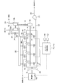
- FIG. 1 shows an overall configuration of a gas engine system according to a first embodiment of the present invention
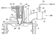
- FIG. 2 is a partial sectional view around a combustion chamber.
- a gas engine with a supercharger for driving a generator will be described as an example, and a configuration having an ignition auxiliary chamber.
- the present invention is not limited to the gas engine of the present embodiment, and can also be applied to the combustion type gas engine of the second embodiment described later.
- the generator 1 is preferable so that a drive object may be shown in figure, it is applicable also in cases other than a generator.
- an engine (gas engine) 2 is provided with a cylinder block 4, a cylinder head 6 and a flywheel 8, and further, a supercharger 10 comprising an exhaust turbine 10 a and a compressor 10 b. Further, the generator 1 is directly attached to the flywheel 8.
- a charge branch 12 is connected to a charge inlet of each cylinder head 6, and each charge branch 12 is connected by a charge outlet of a compressor 10 b and a charge pipe 14.
- the air supply pipe 14 is provided with an air supply cooler 16 that cools the air supplied through the air supply pipe 14.
- an exhaust pipe 18 is connected to an exhaust outlet of each cylinder head 6, and each exhaust pipe 18 is connected by an exhaust inlet of an exhaust turbine 10 a and an exhaust collecting pipe 20.
- An exhaust outlet pipe 22 for discharging the exhaust gas is connected to an exhaust gas outlet of the exhaust turbine 10a.
- an exhaust bypass pipe 24 branched from the inlet side of the exhaust collecting pipe 20 to bypass the exhaust turbine 10a and connected to the exhaust outlet pipe 22 on the outlet side of the exhaust turbine 10a is provided.
- the bus bypass pipe 24 is provided with an exhaust bypass valve 26 that changes the passage area of the exhaust bypass pipe 24 to adjust the supercharging pressure of the compressor 10 b.
- the compressor 10b of the turbocharger 10 is connected to a turbocharger inlet air passage 28 for introducing air from the outside. Further, a gas supply pipe 30 into which the fuel gas is introduced from a fuel gas tank (not shown) for containing the fuel gas is connected to the gas supply main pipe 32 and branched for each cylinder in the middle of the gas supply main pipe 32 A pipe 34 is connected to each air supply branch pipe 12. Further, the fuel gas is pressure-fed to the gas supply main pipe 32 by the gas compressor 31.
- Each gas supply branch 34 is provided with a fuel flow control valve 36 that controls the passage area of each gas supply branch 34, that is, the flow rate of fuel gas. Further, each cylinder head 6 is connected to an auxiliary chamber fuel gas supply pipe 44 for supplying a fuel gas to an ignition device 40 having an auxiliary combustion chamber 38 via a check valve 42.
- a rotational speed sensor 46 for detecting the engine rotational speed, a load sensor 48 for detecting the load of the generator 1, ie, an engine load, a temperature sensor 50 for detecting the outside air temperature, and a humidity sensor 52 for detecting the relative humidity of the outside air are installed. ing.
- FIG. 2 is a partial cross-sectional explanatory view schematically showing a structure around a combustion chamber of the engine 2 of FIG.
- a piston 56 reciprocally slidably fitted in the cylinder 54, a main combustion chamber 58 defined between the upper surface of the piston 56 and the inner surface of the cylinder block 4, and an intake port connected to the main combustion chamber 58 60, an intake valve 62 for opening and closing the intake port 60 and the like.
- a gas mixer 64 is installed on the upstream side of the intake port 60, the gas mixer 64 is connected, the gas supply branch 34 is connected, the fuel gas supplied through the gas supply branch 34, and the charge branch 12 And air supplied through the gas mixer 64 are premixed by the gas mixer 64.
- the gas supply branch pipe 34 may be directly connected to the intake branch pipe 12 without the gas mixer 64 and mixed. Then, it reaches the intake valve 62 through the intake port 60 and is supplied to the main combustion chamber 58 by opening the intake valve 62.
- an auxiliary combustion chamber 38 is formed inside the auxiliary chamber base 66.
- a plurality of injection holes 68 for performing a main combustion by injecting a flame into the main combustion chamber 58 are formed around the tip of the sub-chamber nozzle 66.
- the sub chamber cap 66 is attached to the tip of the nozzle holder 67, and is supplied to the sub chamber fuel gas passage 70 and the sub chamber fuel gas passage 70 inside the nozzle holder 67 into the sub combustion chamber 38.
- a spark plug 72 for igniting the fuel gas is accommodated.
- a fuel gas supply pipe 44 for the sub chamber is connected to the fuel gas passage 70 for the sub chamber, and the fuel gas is supplied into the sub combustion chamber 38 through the check valve 42. The pressurized fuel gas is supplied from the upstream side of the check valve 42 together with the ignition timing of the spark plug 72.
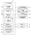
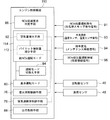
- the engine control device 74 in the gas engine having the above configuration will be described.
- the engine control device 74 mainly controls the ignition timing of the spark plug 72 to ignite the fuel gas supplied into the sub combustion chamber 38, and thereby mixes the mixed gas in the main combustion chamber 58.
- the operation mode is switched between the basic operation mode 80 and the low NOx operation mode 82.
- the basic operation mode 80 is the optimum for the preset engine speed and engine load based on the signals of the engine speed and the engine load detected from the revolution sensor 46 and the load sensor 48, that is, the most fuel consumption Target excess air ratio (first target excess air ratio) at which the ratio improves, and target excess air ratio (first target excess air ratio) calculated using the table of the map of the target ignition timing (first target ignition timing) It refers to an operation in which the ignition timing control means 76 and the excess air ratio control means 78 are controlled with the target ignition timing (first target ignition timing) as a target value.
- a second target ignition timing obtained by delaying the first target ignition timing by a predetermined amount, and a second target air excess ratio obtained by increasing the first target excess air ratio by a predetermined amount are targeted. It refers to an operation in which the ignition timing control means and the excess air ratio control means are controlled as values.
- the ignition timing retarding means 90 for retarding from the first target ignition timing with good fuel efficiency to the second target ignition timing, and the first target excess air ratio with good fuel efficiency (2) air amount increasing means 92 for increasing the air amount to the target excess air ratio.
- the ignition timing retarding means 90 retards and controls the ignition timing of the spark plug 72. Further, the air amount increasing means 92 squeezes the opening of the exhaust bypass valve 26 of the turbocharger 10 to increase the supercharging amount.
- the NOx reduction request determination means 86 determines whether it is necessary to temporarily suppress the NOx emission amount, such as environmental conditions, geographical conditions, engine operation progress conditions, and the like.
- the engine 2 is subjected to basic exhaust gas measures to clear the exhaust gas regulation value, and the operating conditions (first target ignition timing, first target excess air ratio) with optimal fuel consumption are set thereon.
- the operating conditions first target ignition timing, first target excess air ratio
- fuel consumption will be worsened and uneconomical problems Have.
- the NOx reduction request determination means 86 determines whether or not there has been a response to environmental changes, operating periods, and other special NOx emission regulations.
- the conditions determined by the NOx reduction request determination means 86 are as follows.
- the NOx reduction request determination unit 86 determines that NOx reduction is necessary. judge.
- This photochemical smog alert is often generated in summer in urban areas.
- the amount of power generated by summer is required for power generation equipment. Therefore, at the time of photochemical smog generation in the summer season, it is temporarily necessary to operate while suppressing the amount of NOx emission while maintaining the amount of power generation of the generator constant.
- the low NOx operation mode 82 for NOx reduction is set even if the fuel consumption is deteriorated.
- a gas engine for power generation installed near the urban area it is effective as a means for appropriately operating the relationship between the electric energy increase operation in summer and the NOx reduction operation in consideration of fuel consumption reduction.
- the NOx reduction request determination means also when the outside air temperature at which the engine 2 is installed is a predetermined value or more and the humidity is a high temperature or low humidity state of a predetermined value or less. 86 determines that NOx reduction is necessary.
- the outside air temperature is higher than the predetermined value and the humidity is higher than the predetermined value, the supplied air temperature tends to be high, and the combustion temperature in the main combustion chamber 58 tends to be high, and NOx is generated. Since the situation is easy, temporarily switching to the low NOx operation mode and performing the NOx reduction operation can efficiently obtain the NOx reduction effect.
- conditions of high temperature low humidity the case where air temperature is 30 degreeC or more and whose relative humidity is 40% or less is considered, for example.
- the NOx reduction request determination means 86 determines a predetermined period before the next maintenance time or a predetermined period from the first operation start based on the aged data of the gas engine. It is determined that it is necessary when the period is reached.
- the engine 2 is a gas engine for power generation, and maintenance is regularly performed to replace parts against age-related deterioration, but immediately before the maintenance time, the operation time is extended for a long time.
- the exhaust gas condition tends to deteriorate.
- the NOx reduction effect can be efficiently obtained by switching to the low NOx operation mode temporarily and performing the NOx reduction operation.
- the exhaust gas state tends to deteriorate when a predetermined period from the initial operation start is reached, so temporarily switch to the low NOx operation mode at such time It is effective to perform the NOx reduction operation in the NOx reduction effect.
- the NOx reduction request determination means 86 is installed in the case where the engine 2 is the main power engine of a vehicle, a ship or an aircraft, or in this vehicle, ship or aircraft In the case where a moving body of a vehicle, ship or aircraft approaches or enters a NOx emission control area, for example, when the moving source of a vehicle, ship or aircraft is used as a motive power source for the When moving to the airspace, or moving to an area with strict regulations as a special area in the same country, it is necessary to judge.
- NOx detection is required when entering the area by comparing the detection result of location information with the data of NOx regulation level in the area (including airspace and sea area) of the whole world stored in advance. Determine that there is.
- the NOx reduction level is differentiated between approaching and entering, and one-step NOx reduction is performed when approaching within a certain distance, and further NOx reduction is performed when entering the area. It may be performed stepwise as it is performed. In this way, application to a mobile unit moving to a region where the NOx control value is different is facilitated.
- the determination conditions of the NOx reduction request determination means 86 described above can be determined more appropriately by combining them appropriately. For example, combining the time when the photochemical smog alert under the first condition is issued and the time under the high temperature and low humidity condition of the outside air condition under the second condition makes NOx reduction even more necessary. judge.
- the combination of the high temperature and low humidity state of the second condition, the high temperature and low humidity condition, and the timing immediately before the maintenance timing of the third condition, and the timing immediately before the maintenance timing of the third condition It is particularly effective when approaching or entering the NOx emission control area under eye conditions.
- the operation mode switching unit 84 of the engine control device 74 switches the operation mode from the basic operation mode 80 to the low NOx operation mode 82 when the NOx reduction request determination unit 86 determines that the reduction request is necessary, and reduces If it is determined that the request is not, in the basic operation mode 80, the operation mode is maintained, and if in the low NOx operation mode 82, the basic operation mode 80 is switched back.
- the output control means 88 keeps the output of the generator 1 constant by keeping the engine output, that is, the engine speed constant. In the low NOx operation mode 82, the ignition timing is retarded and the air amount is increased, but the ignition timing delay angle, the air increase amount, and the fuel gas amount are controlled so that the engine output does not greatly fluctuate. .
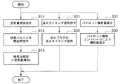
- step S1 when the operation is started, it is determined in step S1 whether the NOx reduction condition is satisfied. This determination is made by the NOx reduction request determination means 86 whether the total NOx amount regulation issuance signal (photochemical smog issuance signal) 91 is issued or the outside air condition signal (detection signals from the temperature sensor 50 and the humidity sensor 52). Is judged based on the signal (93) that the predetermined high temperature and low humidity state is present.
- the NOx reduction request determination means 86 whether the total NOx amount regulation issuance signal (photochemical smog issuance signal) 91 is issued or the outside air condition signal (detection signals from the temperature sensor 50 and the humidity sensor 52). Is judged based on the signal (93) that the predetermined high temperature and low humidity state is present.
- a secular change signal (a signal indicating that the maintenance period is a predetermined period before the maintenance period from information of the maintenance period signal, or a signal that an elapsed time from the initial operation has reached a predetermined period) 94 .
- a NOx emission control area signal (position information signal) 96, it is performed by determining whether the NOx emission control area is approached or within the range.
- step S1 The determination in step S1 is repeated until satisfaction of the NOx reduction condition occurs, and when satisfied, the process proceeds to step S2, and the low NOx operation mode is turned ON by the operation mode switching means 84. Thereafter, the process proceeds to step S3 to implement the low NOx operation mode.
- step S4 the transition to the low NOx operation mode is completed by the implementation of the flow shown in FIG.
- step S5 it is determined whether the NOx reduction condition is satisfied as in step S1. If the determination result is "Yes”, the process proceeds to step S6, the low NOx operation mode 82 is continued, and the process is repeated until the NOx reduction condition becomes negative. Then, if the NOx reduction condition is not satisfied, the process proceeds to step S7, and the low NOx operation mode 82 is turned off. Thereafter, the process proceeds to step S8 to cancel the low NOx operation mode.
- the release of the low NOx operation mode is the reverse of the subroutine shown in FIG. 5, and the air amount command value is decreased and the ignition timing is advanced. Then, in step S9, the reverse of the flow shown in FIG. 5 is performed to complete the low NOx operation mode stop and return to the basic operation mode 80.
- step S11 the air amount increasing means 92 is instructed to increase the air amount, and at step S12 the opening of the exhaust bypass valve 26 is operated in the closing direction to supply. Increase air pressure (increase air supply).
- step S21 the ignition timing retarding means 90 is instructed to retard, and in step S22, the ignition timing of the spark plug 72 is retarded.
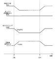
- a time chart in the low NOx operation mode 82 by the above engine control device 74 is shown in FIG. It shows the changes of the NOx concentration in the exhaust gas from ON to OFF of the low NOx operation mode 82, the engine output (generator output), the retardation of the ignition timing, and the air amount increase.
- the ignition timing is retarded at a rate of 2 deg / 5 minutes, and the air amount is increased at a rate of 1% / 5 minutes.
- the engine output is controlled to be maintained substantially constant.
- switching from the time of OFF is performed by returning the air amount and the ignition timing at the same ratio.
- the operation mode is switched only when it is necessary to temporarily suppress the NOx emission amount due to environmental conditions of temperature and humidity, geographical conditions, engine operation progress conditions, etc.
- Control is performed by the excess air ratio control means 78 based on a second target excess air ratio that the means 84 switches from the basic operation mode 80 to the low NOx operation mode 82 and increases the first target excess air ratio. Further, control based on the second target ignition timing, which is the first target ignition timing delayed, is performed by the ignition timing control means 76.
- the second embodiment will be described with reference to FIGS.
- the second embodiment differs from the first embodiment only in the combustion system, and instead of the spark plug type secondary combustion chamber structure of the first embodiment, it has a micro pilot type secondary combustion chamber structure.
- the other configuration is the same as that of the first embodiment, and the same reference numeral is assigned to the same configuration and the description is omitted.
- the auxiliary combustion chamber 38 is formed inside the auxiliary chamber base 66 attached to the tip portion of the nozzle holder 102, and the fuel injection valve 104 is installed inside the nozzle holder 102.
- Liquid fuel is supplied to the fuel injection valve 104 from an inlet pipe 106 for liquid fuel (light oil).
- the premixed mixed gas introduced into the main combustion chamber 58 through the intake valve 62 at the intake stroke passes through the injection hole 68 formed at the tip portion of the sub chamber cap 66 from the main combustion chamber 58 at the compression stroke.
- the liquid fuel is pilot-injected into the mixed gas from the fuel injection valve 104 and burned, and an ignition flame generated by this combustion passes through the injection hole 68 to the main combustion chamber.
- the mixed gas of the premix in the main combustion chamber 58 is burned by causing the fuel to flow back to 58.
- the engine control device 110 is obtained by adding the reduction of the pilot injection amount to the first embodiment as shown by the dotted line portion in FIG.
- the flame strength of the ignition flame is reduced to lower the combustion temperature in the main combustion chamber 58, thereby reducing the NOx generation amount.
- a command to decrease the pilot injection amount is issued in step S31, and the injection amount is decreased by the pilot injection controller (not shown) in step S32.
- the retardation of the ignition timing of the spark plug in steps S21 and S22 in FIG. 5 is replaced with the retardation of the injection timing of the pilot injection.
- the micro pilot sub-combustion chamber structure as in the second embodiment as in the first embodiment, it is necessary to always increase the target excess air ratio and further delay the ignition timing to perform the NOx reduction operation.
- the combustion chamber structure having the sub combustion chamber structure has been described.
- a direct injection structure in which a pilot fuel (liquid fuel) is directly injected into the main combustion chamber may be employed.
- the gas supply pipe 30 to which the fuel gas is introduced from the fuel gas tank (not shown) is connected to the gas supply main pipe 32.
- each cylinder is branched to form a gas supply branch 34 and connected to each air supply branch 12.
- a gas mixer 116 is installed upstream of the compressor 10 b of the turbocharger 10 to supply fuel gas through a gas control valve 118 to generate a premixed mixed gas.
- both the mixing in the supply branch 12 and the mixing upstream of the turbocharger 10 may be provided.
- a gas supply pipe 30 for introducing fuel gas from a fuel gas tank is branched into a turbocharger side gas supply pipe 30a and a cylinder side gas supply pipe 30b, and the turbocharger side gas supply pipe 30a is connected to the gas mixer 116.
- the amount of fuel gas regulated by the gas regulating valve 118 is premixed with air.
- the gas mixer 116 preferably a venturi mixer is used.
- the NOx suppression operation is performed when necessary environmental conditions or geographical conditions occur to temporarily suppress the NOx emission, and stable operation with emphasis on fuel efficiency is performed in other cases.
- NOx reduction and fuel efficiency improvement can be achieved, and therefore, it is suitable for use in a gas engine for power generation or a gas engine provided in a moving body.
Landscapes
- Engineering & Computer Science (AREA)
- Chemical & Material Sciences (AREA)
- Mechanical Engineering (AREA)
- General Engineering & Computer Science (AREA)
- Combustion & Propulsion (AREA)
- Chemical Kinetics & Catalysis (AREA)
- Oil, Petroleum & Natural Gas (AREA)
- General Chemical & Material Sciences (AREA)
- Theoretical Computer Science (AREA)
- Signal Processing (AREA)
- Toxicology (AREA)
- Health & Medical Sciences (AREA)
- Combined Controls Of Internal Combustion Engines (AREA)
- Electrical Control Of Air Or Fuel Supplied To Internal-Combustion Engine (AREA)
- Output Control And Ontrol Of Special Type Engine (AREA)
Abstract
Description
このような、一時的にNOx抑制が必要な場合に対応するために、高いレベルの対策設備、若しくは対策制御を常に設置若しくは作動させておくと、エンジンの燃料消費率の悪化や設備費の増大を招く。
そのため、一時的にNOx抑制運転を実行することによって、常にNOx抑制運転を行う場合に比べて燃費悪化や設備費の増大を抑えことができ経済的である。 In other words, when environmental conditions or geographical conditions occur that require the NOx emission to be temporarily suppressed, for example, when an alert warning of photochemical smog is issued in summer in urban areas, the cause is the generation of photochemical smog. When it is necessary to temporarily suppress certain NOx, or when engine operation time approaches a predetermined maintenance time, it may be temporarily suppressed during a period until maintenance is performed when deterioration of the exhaust gas concentration is concerned. It is necessary to temporarily suppress when entering into the NOx control area or entering the control country, as in the case of high temperature, low humidity and high combustion temperature, as in marine or mobile engines. May occur, etc.
In order to cope with such a case where NOx reduction is temporarily required, if a high level countermeasure facility or countermeasure control is always installed or operated, the fuel consumption rate of the engine will deteriorate and the facility cost will increase. Cause.
Therefore, by executing the NOx suppression operation temporarily, deterioration in fuel consumption and increase in equipment cost can be suppressed compared to the case where NOx suppression operation is always performed, which is economical.
高温低湿度の条件としては、例えば、気温が30℃以上であって、相対湿度が40%以下の場合である。 With this configuration, when the outside air temperature is higher than or equal to the predetermined value and the humidity is higher than the predetermined value in the low humidity condition, the supplied air temperature is high and NOx is likely to be generated. By switching to the low NOx operation mode and performing the NOx reduction operation, the NOx reduction effect can be obtained efficiently.
The conditions of high temperature and low humidity are, for example, the case where the air temperature is 30 ° C. or more and the relative humidity is 40% or less.
従って、過給機付きのガスエンジンおいて、一時的に、低NOx運転モードに切り換えてNOx低減運転を行うことで、効率よくNOx低減効果を得ることができる。 By configuring in this manner, it is possible to increase the excess air ratio by controlling the exhaust bypass flow rate of the supercharger to increase the supercharging amount. This enables operation of NOx reduction.
Therefore, in the gas engine with a supercharger, the NOx reduction effect can be efficiently obtained by temporarily switching to the low NOx operation mode and performing the NOx reduction operation.
従って、ガスエンジンがパイロット噴射式の燃焼室構造からなる場合においては、一時的に、低NOx運転モードに切り替えてNOx低減運転を行うことで、効率よくNOx低減効果を得ることができる。 By configuring in this manner, the excess air ratio can be increased by reducing the pilot fuel. This enables operation of NOx reduction.
Therefore, when the gas engine has a pilot injection combustion chamber structure, the NOx reduction effect can be efficiently obtained by temporarily switching to the low NOx operation mode and performing the NOx reduction operation.
図1は、本発明の第1実施例に係るガスエンジンシステムの全体構成図を示し、図2は燃焼室周りの部分断面図である。本実施例では、一例として発電機を駆動するための過給機付きガスエンジンで、且つ点火用副室を有する構成につき説明する。
本実施形態のガスエンジンに限定されるものではなく、後述する第2実施形態の燃焼方式によるガスエンジンにも適用可能である。また、駆動対象は図示されるように発電機1が好ましいが、発電機以外の場合にも適用可能である。 First Embodiment
FIG. 1 shows an overall configuration of a gas engine system according to a first embodiment of the present invention, and FIG. 2 is a partial sectional view around a combustion chamber. In this embodiment, a gas engine with a supercharger for driving a generator will be described as an example, and a configuration having an ignition auxiliary chamber.
The present invention is not limited to the gas engine of the present embodiment, and can also be applied to the combustion type gas engine of the second embodiment described later. Moreover, although the
各シリンダヘッド6の給気入口には、給気枝管12がそれぞれ接続され、各給気枝管12はコンプレッサ10bの給気出口と給気管14によって接続されている。給気管14には、該給気管14を流れる給気を冷却する給気冷却器16が設けられている。 In FIG. 1, an engine (gas engine) 2 is provided with a
A
また、各シリンダヘッド6には、副燃焼室38を有する着火装置40に燃料ガスを、逆止弁42を介して供給する副室用燃料ガス供給管44がそれぞれ接続されている。 Each
Further, each
そして、吸気ポート60を経て吸気弁62に達し、吸気弁62の開弁によって主燃焼室58に供給される。 A
Then, it reaches the
該副室口金66はノズルホルダー67の先端部に取り付けられ、ノズルホルダー67の内部には副室用燃料ガス通路70、および該副室用燃料ガス通路70から副燃焼室38内に供給される燃料ガスに点火する点火プラグ72が収納されている。副室用燃料ガス通路70には、副室用燃料ガス供給管44が接続され、逆止弁42を介して副燃焼室38内へ燃料ガスの供給が行われる。逆止弁42の上流側から加圧燃料ガスが点火プラグ72の点火時期と合わせて供給されるようになっている。 Further, an
The
エンジン制御装置74は、図3に示すように主に前記点火プラグ72の点火時期を制御して副燃焼室38内に供給される燃料ガスを着火して、主燃焼室58内の混合ガスの着火時期を制御する着火時期制御手段76と、主燃焼室58内の空気過剰率を制御する空気過剰率制御手段78と、基本運転モード80と低NOx運転モード82との運転モードの切換えを行う運転モード切換え手段84と、環境条件や地理的条件やエンジン運転経過条件の少なくともいずれかの条件によって、NOx排出量を一時的に抑制する必要が生じたか否かを判定するNOx低減要求判定手段86と、さらに、エンジン出力、つまり発電機1の出力電力を制御する出力制御手段88と、を有している。 Next, the
As shown in FIG. 3, the
エンジン2は、排ガス規制値をクリアするために基本となる排ガス対策は施されて、その上で最適燃費での運転条件(第1目標点火時期、第1目標空気過剰率)が設定されている。
しかし、環境変化、稼働期間、その他特別なNOx排ガス規制への対応のために、さらに燃費を犠牲にしてNOx対策を施した条件で運転を行うと、かえって燃費を悪化させ、経済的でない問題を有する。 Further, the NOx reduction request determination means 86 determines whether it is necessary to temporarily suppress the NOx emission amount, such as environmental conditions, geographical conditions, engine operation progress conditions, and the like.
The
However, if operating under conditions where NOx measures are taken at the expense of fuel consumption in order to cope with environmental changes, operating periods, and other special NOx emission regulations, fuel consumption will be worsened and uneconomical problems Have.
このNOx低減要求判定手段86によって判定される条件は次の場合である。 Therefore, it is determined by the NOx reduction request determination means 86 whether or not there has been a response to environmental changes, operating periods, and other special NOx emission regulations.
The conditions determined by the NOx reduction request determination means 86 are as follows.
この光化学スモッグ注意報は、都市部の夏場においてよく発生される。また、一般的に発電設備では夏場発電量が必要になる。従って、夏場において光化学スモッグ発生時においては、発電機の発電量を一定に維持しつつ、NOx排出量を抑えての運転が一時的に必要となる。この場合には、燃費の悪化を伴ってもNOx低減用の低NOx運転モード82とする。
特に、都市部近郊に設置された発電用のガスエンジンにおいて、夏場の電力量増大運転と、NOx低減運転との関係を、燃費低減を考慮して適切運転する手段として効果的である。 For example, as the determination condition (the first condition), when the photochemical smog warning is issued in the area where the
This photochemical smog alert is often generated in summer in urban areas. In addition, in general, the amount of power generated by summer is required for power generation equipment. Therefore, at the time of photochemical smog generation in the summer season, it is temporarily necessary to operate while suppressing the amount of NOx emission while maintaining the amount of power generation of the generator constant. In this case, the low
In particular, in a gas engine for power generation installed near the urban area, it is effective as a means for appropriately operating the relationship between the electric energy increase operation in summer and the NOx reduction operation in consideration of fuel consumption reduction.
このため、光化学スモッグ注意報が発令した場合には、光化学スモッグの発生原因である、NOx排出量を低減するために、一時的に、低NOx運転モードに切り替えてNOx低減運転を行うことで、効率よくNOx低減効果が得られる。 When a volatile organic compound contained as a solvent in paints, adhesives, etc. and NOx (nitrogen oxide) contained in exhaust gas from automobiles and factories receive ultraviolet light from the sun and cause a chemical reaction, photochemical oxidants The new substance is generated, the temperature is high, the wind is weak, and the day when the sunlight is strong, the concentration of photochemical oxidant in the atmosphere becomes high, and so-called photochemical smog occurs.
For this reason, when the photochemical smog warning is issued, the NOx reduction operation mode is temporarily performed by switching to the low NOx operation mode in order to reduce the NOx emission amount that is the cause of the generation of the photochemical smog. The NOx reduction effect can be obtained efficiently.
外気温度が所定値以上であり、且つ湿度が所定値以下の高温低湿度状態であるときには、給気温度が高くなり主燃焼室58内の燃焼温度も高温化する傾向があり、NOxが発生しやすい状況であるため、一時的に、低NOx運転モードに切り替えてNOx低減運転を行うことで、効率よくNOx低減効果が得られる。
なお、高温低湿度の条件としては、例えば、気温が30℃以上であって、相対湿度が40%以下の場合が考えられる。 In addition, as the determination condition (the second condition), the NOx reduction request determination means also when the outside air temperature at which the
When the outside air temperature is higher than the predetermined value and the humidity is higher than the predetermined value, the supplied air temperature tends to be high, and the combustion temperature in the
In addition, as conditions of high temperature low humidity, the case where air temperature is 30 degreeC or more and whose relative humidity is 40% or less is considered, for example.
そのように時期においては一時的に、低NOx運転モードに切り替えてNOx低減運転を行うことで、効率よくNOx低減効果を得ることができる。また、定期的なメンテナンス時期とは関連なく、初期の運転開始からの所定期間に達したときには排ガス状態が悪化する傾向にあるため、そのように時期において、一時的に、低NOx運転モードに切り替えてNOx低減運転を行うことは、NOx低減効果において効果的である。 The
As described above, the NOx reduction effect can be efficiently obtained by switching to the low NOx operation mode temporarily and performing the NOx reduction operation. Also, regardless of the regular maintenance time, the exhaust gas state tends to deteriorate when a predetermined period from the initial operation start is reached, so temporarily switch to the low NOx operation mode at such time It is effective to perform the NOx reduction operation in the NOx reduction effect.
なお、接近した時と、入った時とで、NOx低減レベルに差を付けて、一定距離内に近づいた時点で一段階NOx低減を実行し、その地域内に入った段階で更にNOx低減を実行するように、段階的に実行してもよい。
このようにすることで、NOx規制値が異なる地域に移動する移動体への適用が容易になる。 Specifically, NOx detection is required when entering the area by comparing the detection result of location information with the data of NOx regulation level in the area (including airspace and sea area) of the whole world stored in advance. Determine that there is.
Note that the NOx reduction level is differentiated between approaching and entering, and one-step NOx reduction is performed when approaching within a certain distance, and further NOx reduction is performed when entering the area. It may be performed stepwise as it is performed.
In this way, application to a mobile unit moving to a region where the NOx control value is different is facilitated.
また、2つ目の条件の外気条件の高温低湿度状態のときと、3つ目の条件のメンテナンス時期の直前時期との組み合わせ、また3つ目の条件のメンテナンス時期の直前時期と、4つ目の条件のNOx排出量規制地域に近づいたとき、もしくは入ったときの場合が特に有効である。 Further, the determination conditions of the NOx reduction request determination means 86 described above can be determined more appropriately by combining them appropriately. For example, combining the time when the photochemical smog alert under the first condition is issued and the time under the high temperature and low humidity condition of the outside air condition under the second condition makes NOx reduction even more necessary. judge.
In addition, the combination of the high temperature and low humidity state of the second condition, the high temperature and low humidity condition, and the timing immediately before the maintenance timing of the third condition, and the timing immediately before the maintenance timing of the third condition It is particularly effective when approaching or entering the NOx emission control area under eye conditions.
まず、運転を開始すると、ステップS1で、NOx低減条件が成立か否かが判定される。この判定は、NOx低減要求判定手段86によって、NOx総量規制発令信号(光化学スモッグ発令信号)91が発せられているか否か、または、外気条件信号(温度センサ50、および湿度センサ52からの検出信号によって所定の高温低湿度状態にあることの信号)93を基に判定される。
また、経年変化信号(メンテナンス時期信号の情報からメンテナンス時期の所定期間前にあることの信号、または運転初期からの経過時間が所定の時期に達していることの信号)94を基に判定される。
また、NOx排出量規制地域信号(位置情報信号)96を基に、NOx排出量規制地域に近付いているか、範囲内に入ったかを判定することで行われる。 Next, the control flow of the
First, when the operation is started, it is determined in step S1 whether the NOx reduction condition is satisfied. This determination is made by the NOx reduction request determination means 86 whether the total NOx amount regulation issuance signal (photochemical smog issuance signal) 91 is issued or the outside air condition signal (detection signals from the
In addition, it is determined based on a secular change signal (a signal indicating that the maintenance period is a predetermined period before the maintenance period from information of the maintenance period signal, or a signal that an elapsed time from the initial operation has reached a predetermined period) 94 .
Further, based on the NOx emission control area signal (position information signal) 96, it is performed by determining whether the NOx emission control area is approached or within the range.
そして、ステップS9で、図5に示すフローの逆を実施して低NOx運転モード停止を完了して、基本運転モード80に戻す。 Next, in step S5, it is determined whether the NOx reduction condition is satisfied as in step S1. If the determination result is "Yes", the process proceeds to step S6, the low
Then, in step S9, the reverse of the flow shown in FIG. 5 is performed to complete the low NOx operation mode stop and return to the
低NOx運転モード82へ移行する場合には、例えば、点火タイミングは2deg/5分の割合で遅角させ、空気量は1%/5分の割合で増加させる。エンジン出力は、ほぼ一定に維持されるように制御される。また、基本運転モード80へ戻る場合も、低NOx運転モード82へ移行する場合と同様に、OFFの時点から、同一の割合で空気量と点火タイミングを戻すことで切り換えられる。 A time chart in the low
When shifting to the low
図5、7、8を参照して第2実施形態について説明する。
第2実施形態は第1実施形態と燃焼方式が異なるだけであり、第1実施形態の点火プラグ式の副燃焼室構造に代えてマイクロパイロット式の副燃焼室構造となっている。その他の構成は第1実施形態と同様であり、同一構成については同一符号を付して説明を省略する。 Second Embodiment
The second embodiment will be described with reference to FIGS.
The second embodiment differs from the first embodiment only in the combustion system, and instead of the spark plug type secondary combustion chamber structure of the first embodiment, it has a micro pilot type secondary combustion chamber structure. The other configuration is the same as that of the first embodiment, and the same reference numeral is assigned to the same configuration and the description is omitted.
そして、吸気行程時に吸気弁62を介して主燃焼室58に導入された予混合の混合ガスが、圧縮行程時に主燃焼室58から副室口金66の先端部分に形成された噴孔68を通って、副燃焼室38内に導入され、その混合ガス中に燃料噴射弁104から液体燃料がパイロット噴射されて燃焼し、この燃焼により発生した着火火炎が、噴孔68を通って該主燃焼室58に還流噴出させて主燃焼室58の予混合の混合ガスを燃焼させる。 As shown in FIG. 7, in the
Then, the premixed mixed gas introduced into the
なお、第2実施形態において、図5におけるステップS21、S22の点火プラグの点火タイミングの遅角は、パイロット噴射の噴射タイミングの遅角と読み替える。 The
In the second embodiment, the retardation of the ignition timing of the spark plug in steps S21 and S22 in FIG. 5 is replaced with the retardation of the injection timing of the pilot injection.
また、第2実施形態においては、副燃焼室構造を備えた燃焼室構造について説明したが、パイロット燃料(液体燃料)を主燃焼室に直接噴射する直噴式構造としてもよい。 Also in the micro pilot sub-combustion chamber structure as in the second embodiment, as in the first embodiment, it is necessary to always increase the target excess air ratio and further delay the ignition timing to perform the NOx reduction operation. However, by performing the stable operation in the
Further, in the second embodiment, the combustion chamber structure having the sub combustion chamber structure has been described. However, a direct injection structure in which a pilot fuel (liquid fuel) is directly injected into the main combustion chamber may be employed.
2 エンジン(ガスエンジン)
4 シリンダブロック
6 シリンダヘッド
8 フライホイール
10 過給機
10a 排気タービン
10b コンプレッサ
26 排気バイパス弁
38 副燃焼室
46 回転数センサ
48 負荷センサ
50 温度センサ
52 湿度センサ
58 主燃焼室(燃焼室)
74、110 エンジン制御装置(排ガス制御装置)
76 着火時期制御手段
78 空気過剰率制御手段
80 基本運転モード
82 低NOx運転モード
84 運転モード切換え手段
86 NOx低減要求判定手段
88 出力制御手段
90 点火タイミング遅角手段
91 NOx総量規制発令信号
92 空気量増大手段
93 外気条件信号
94 経年変化信号
96 NOx排出量規制地域信号
112 パイロット噴射量減少手段 1
4
74, 110 Engine control unit (exhaust gas control unit)
76 Ignition timing control means 78 Air excess ratio control means 80
Claims (7)
- 燃料ガスと空気とを混合し、混合した混合ガスを燃焼室に供給するガスエンジンの排ガス制御装置において、
燃焼室内に供給される混合ガスの着火時期を制御する着火時期制御手段と、
燃焼室内の空気過剰率を制御する空気過剰率制御手段と、
エンジン回転数とエンジン負荷に基づいて燃料消費率が最適な着火時期および空気過剰率として設定された第1目標着火時期および第1目標空気過剰率を目標値として前記着火時期制御手段および空気過剰率制御手段を制御する基本運転モードと、
環境条件や地理的条件やエンジン運転経過条件の少なくともいずれかの条件によって、NOx排出量を一時的に抑制するか否かを判定するNOx低減要求判定手段と、
前記第1目標着火時期を遅延させた第2目標着火時期および前記第1目標空気過剰率を増大させた第2目標空気過剰率を目標値として前記着火時期制御手段および空気過剰率制御手段を制御する低NOx運転モードと、
前記NOx低減要求判定手段によって低減要求があった場合に、前記低NOx運転モードに切り替えて、前記NOx低減要求が解除されるまで該低NOx運転モードを継続し、前記NOx低減要求が解除された場合に前記基本運転モードに切り換える運転モード切換え手段と、を備えたことを特徴とするガスエンジンの排ガス制御装置。 In an exhaust gas control apparatus of a gas engine, which mixes fuel gas and air and supplies the mixed gas to a combustion chamber,
Ignition timing control means for controlling the ignition timing of the mixed gas supplied into the combustion chamber;
Excess air ratio control means for controlling the excess air ratio in the combustion chamber;
The ignition timing control means and the excess air ratio with the first target ignition timing and the first target excess air ratio set as the optimal ignition timing and excess air ratio based on the engine speed and the engine load A basic operation mode for controlling the control means;
NOx reduction request determination means for determining whether or not to suppress NOx emissions temporarily based on at least one of environmental conditions, geographical conditions, and engine operation progress conditions;
A second target ignition timing delayed from the first target ignition timing and a second target excess air ratio increased from the first target excess air ratio are controlled as target values to control the ignition timing control means and the excess air ratio control means Low NOx operation mode,
When there is a reduction request by the NOx reduction request determination means, the mode is switched to the low NOx operation mode, the low NOx operation mode is continued until the NOx reduction request is cancelled, and the NOx reduction request is cancelled. An exhaust gas control apparatus for a gas engine, comprising: operation mode switching means for switching to the basic operation mode. - 前記NOx低減要求判定手段は、前記ガスエンジンが設置された地域おびその周辺に光化学スモッグ注意報が発令されたときに、判定を要とすることを特徴とする請求項1記載のガスエンジンの排ガス制御装置。 The exhaust gas from the gas engine according to claim 1, wherein the NOx reduction request determination means requires the determination when a photochemical smog warning is issued in the area where the gas engine is installed and in the vicinity thereof. Control device.
- 前記NOx低減要求判定手段は、前記ガスエンジンが設置されている外気温度が所定値以上であり、且つ湿度が所定値以下の高温低湿度状態であるときに、判定を要とすることを特徴とする請求項1記載のガスエンジンの排ガス制御装置。 The NOx reduction request determination means is required to make a determination when the temperature of the outside air where the gas engine is installed is equal to or higher than a predetermined value and the humidity is equal to or lower than a predetermined value. An exhaust gas control apparatus for a gas engine according to claim 1.
- 前記NOx低減要求判定手段は、前記ガスエンジンの運転経年データに基づいて、次回メンテナンス時期前の所定期間、もしくは、最初の運転開始から所定期間に達したときに、判定を要とすることを特徴とする請求項1記載のガスエンジンの排ガス制御装置。 The NOx reduction request determination means is characterized in that the determination is required when the predetermined period before the next maintenance time or the predetermined period from the first operation start is reached based on the aging data of the gas engine. An exhaust gas control apparatus for a gas engine according to claim 1, wherein
- 前記NOx低減要求判定手段は、前記ガスエンジンを搭載した移動体が、NOx排出量規制地域に近づいたとき、もしくは入ったときに、判定を要とすることを特徴とする請求項1記載のガスエンジンの排ガス制御装置。 The gas according to claim 1, wherein the NOx reduction request determination means requires determination when the mobile unit mounted with the gas engine approaches or enters a NOx emission control area. Engine exhaust control system.
- 前記ガスエンジンには過給機が備えられ、前記低NOx運転モードは、空気過剰率を増大するように、前記過給機を制御することを特徴とする請求項1~5の何れか1項に記載のガスエンジンの排ガス制御装置。 The said gas engine is equipped with a supercharger, The said low NOx operation mode controls the said supercharger so that an air excess rate may be increased, Any one of the Claims 1-5 characterized by the above-mentioned. An exhaust gas control device for a gas engine according to claim 1.
- 前記ガスエンジンがパイロット噴射式の燃焼室構造からなり、前記低NOx運転モードにおける空気過剰率の増大を、副室内もしくは主室内に噴射するパイロット燃料を減少させることで行うことを特徴とする請求項1~5の何れか1項に記載のガスエンジンの排ガス制御装置。 The gas engine has a pilot-injection combustion chamber structure, and the excess air ratio in the low NOx operation mode is increased by reducing the pilot fuel injected into the sub chamber or the main chamber. An exhaust gas control apparatus for a gas engine according to any one of 1 to 5.
Priority Applications (4)
| Application Number | Priority Date | Filing Date | Title |
|---|---|---|---|
| KR1020157025570A KR101789897B1 (en) | 2013-03-19 | 2014-02-20 | Exhaust gas control device of gas engine |
| US14/777,432 US9551285B2 (en) | 2013-03-19 | 2014-02-20 | Exhaust gas control device of gas engine |
| EP14767698.5A EP2977595B1 (en) | 2013-03-19 | 2014-02-20 | Exhaust gas control device for a gas engine |
| CN201480011512.6A CN105008698B (en) | 2013-03-19 | 2014-02-20 | The exhaust control device of gas engine |
Applications Claiming Priority (2)
| Application Number | Priority Date | Filing Date | Title |
|---|---|---|---|
| JP2013056775A JP5980151B2 (en) | 2013-03-19 | 2013-03-19 | Exhaust gas control device for gas engine |
| JP2013-056775 | 2013-03-19 |
Publications (1)
| Publication Number | Publication Date |
|---|---|
| WO2014148192A1 true WO2014148192A1 (en) | 2014-09-25 |
Family
ID=51579884
Family Applications (1)
| Application Number | Title | Priority Date | Filing Date |
|---|---|---|---|
| PCT/JP2014/054052 WO2014148192A1 (en) | 2013-03-19 | 2014-02-20 | Exhaust gas control device of gas engine |
Country Status (6)
| Country | Link |
|---|---|
| US (1) | US9551285B2 (en) |
| EP (1) | EP2977595B1 (en) |
| JP (1) | JP5980151B2 (en) |
| KR (1) | KR101789897B1 (en) |
| CN (1) | CN105008698B (en) |
| WO (1) | WO2014148192A1 (en) |
Cited By (2)
| Publication number | Priority date | Publication date | Assignee | Title |
|---|---|---|---|---|
| US9551285B2 (en) | 2013-03-19 | 2017-01-24 | Mitsubishi Heavy Industries, Ltd. | Exhaust gas control device of gas engine |
| EP3327280A4 (en) * | 2015-07-23 | 2018-05-30 | Yanmar Co., Ltd. | Engine device |
Families Citing this family (24)
| Publication number | Priority date | Publication date | Assignee | Title |
|---|---|---|---|---|
| US9172217B2 (en) | 2010-11-23 | 2015-10-27 | Woodward, Inc. | Pre-chamber spark plug with tubular electrode and method of manufacturing same |
| US8584648B2 (en) | 2010-11-23 | 2013-11-19 | Woodward, Inc. | Controlled spark ignited flame kernel flow |
| US9476347B2 (en) | 2010-11-23 | 2016-10-25 | Woodward, Inc. | Controlled spark ignited flame kernel flow in fuel-fed prechambers |
| US9856848B2 (en) | 2013-01-08 | 2018-01-02 | Woodward, Inc. | Quiescent chamber hot gas igniter |
| US9765682B2 (en) | 2013-06-10 | 2017-09-19 | Woodward, Inc. | Multi-chamber igniter |
| US20190301351A1 (en) | 2015-08-24 | 2019-10-03 | Akela Industries Inc. | Pre-combustion chamber apparatus and method for pre-combustion |
| JP6561362B2 (en) * | 2014-10-29 | 2019-08-21 | 株式会社三井E&Sマシナリー | Ship engine operation system |
| US9653886B2 (en) | 2015-03-20 | 2017-05-16 | Woodward, Inc. | Cap shielded ignition system |
| US9840963B2 (en) | 2015-03-20 | 2017-12-12 | Woodward, Inc. | Parallel prechamber ignition system |
| AT517111B1 (en) * | 2015-06-29 | 2016-11-15 | Ge Jenbacher Gmbh & Co Og | Internal combustion engine with a control device |
| US9890689B2 (en) * | 2015-10-29 | 2018-02-13 | Woodward, Inc. | Gaseous fuel combustion |
| DE102015015343A1 (en) * | 2015-11-26 | 2017-06-01 | Man Diesel & Turbo Se | Method and control device for operating an engine |
| US10208651B2 (en) * | 2016-02-06 | 2019-02-19 | Prometheus Applied Technologies, Llc | Lean-burn pre-combustion chamber |
| JP6919854B2 (en) * | 2017-03-31 | 2021-08-18 | 国立研究開発法人 海上・港湾・航空技術研究所 | Engine exhaust control system and ships equipped with it |
| SE542081C2 (en) * | 2017-04-21 | 2020-02-18 | Scania Cv Ab | Gas Engine, Method for Operating a Gas Engine and Generator Set |
| US10626840B2 (en) * | 2017-06-29 | 2020-04-21 | Ford Global Technologies, Llc | Methods and systems for spark timing control |
| SE542084C2 (en) | 2017-07-14 | 2020-02-25 | Lean Marine Sweden Ab | Method for controlling the propulsion of a ship by determined cylinder top pressure |
| DE102017214092B4 (en) * | 2017-08-11 | 2019-07-04 | Continental Automotive Gmbh | Control method and internal combustion engine |
| KR102422138B1 (en) * | 2017-11-01 | 2022-07-18 | 현대자동차주식회사 | Hybrid vehicle and method of controlling engine operation for the same |
| AT16719U1 (en) * | 2018-12-21 | 2020-07-15 | Innio Jenbacher Gmbh & Co Og | Cylinder head for an internal combustion engine |
| US11415041B2 (en) | 2019-09-16 | 2022-08-16 | Woodward, Inc. | Flame triggered and controlled volumetric ignition |
| WO2021163863A1 (en) * | 2020-02-18 | 2021-08-26 | 潍柴动力股份有限公司 | Engine control method and device |
| US11739702B2 (en) * | 2021-02-23 | 2023-08-29 | Aramco Services Company | Reheated residual gas ignitor |
| CN114183263B (en) * | 2021-10-29 | 2024-03-05 | 东风商用车有限公司 | Engine control method with multiple control modes |
Citations (12)
| Publication number | Priority date | Publication date | Assignee | Title |
|---|---|---|---|---|
| JPH11351047A (en) * | 1998-06-11 | 1999-12-21 | Yanmar Diesel Engine Co Ltd | Control method for internal combustion engine |
| JP2001107809A (en) * | 1999-10-06 | 2001-04-17 | Goto Ikueikai | Gas fuel internal combustion engine |
| JP2002309986A (en) * | 2001-04-13 | 2002-10-23 | Sanyo Electric Co Ltd | Engine control device and engine-driven heat pump device using the same |
| JP2003148187A (en) | 2001-11-12 | 2003-05-21 | Tokyo Gas Co Ltd | Device and method for controlling internal combustion engine |
| JP2003148781A (en) | 2001-11-15 | 2003-05-21 | Mitsubishi Electric Corp | Ventilator |
| JP2003239748A (en) * | 2002-02-18 | 2003-08-27 | Yanmar Co Ltd | Compressed self-ignition type internal combustion engine |
| JP2005188369A (en) * | 2003-12-25 | 2005-07-14 | Yanmar Co Ltd | Air fuel ratio control device |
| JP2010007518A (en) * | 2008-06-25 | 2010-01-14 | Nissan Motor Co Ltd | Exhaust emission control device and exhaust emission control method for diesel engine |
| JP2011127544A (en) * | 2009-12-18 | 2011-06-30 | Yanmar Co Ltd | Gas engine control device |
| WO2011125976A1 (en) * | 2010-04-02 | 2011-10-13 | 株式会社マサインタナショナル | Heat engine and power generation system using the heat engine |
| JP2011247238A (en) * | 2010-05-31 | 2011-12-08 | Mitsubishi Heavy Ind Ltd | Gas engine |
| JP2013024047A (en) * | 2011-07-15 | 2013-02-04 | Daihatsu Diesel Mfg Co Ltd | Fuel injection valve |
Family Cites Families (14)
| Publication number | Priority date | Publication date | Assignee | Title |
|---|---|---|---|---|
| JPH08121201A (en) | 1994-10-27 | 1996-05-14 | Tokyo Gas Co Ltd | Knocking control method and device for gas engine |
| JP3337931B2 (en) * | 1997-01-30 | 2002-10-28 | マツダ株式会社 | In-cylinder injection engine |
| JP4026991B2 (en) | 1999-07-23 | 2007-12-26 | 三洋電機株式会社 | Gas heat pump type air conditioner |
| JP2005226621A (en) | 2004-02-16 | 2005-08-25 | Mitsubishi Heavy Ind Ltd | Engine system including instrumentation engine and operation method thereof |
| US7168411B2 (en) | 2004-10-01 | 2007-01-30 | Southwest Research Institute | Closed loop engine control for regulating NOx emissions, using a two-dimensional fuel-air curve |
| DE112006000529B4 (en) * | 2005-03-03 | 2016-02-18 | General Motors Global Technology Operations, Inc. | A method of controlling transient loads between lean and stoichiometric combustion modes of direct injection self-ignition combustion engines |
| JP4482491B2 (en) * | 2005-06-17 | 2010-06-16 | 本田技研工業株式会社 | Control device for internal combustion engine |
| US7992377B2 (en) * | 2006-12-14 | 2011-08-09 | GM Global Technology Operations LLC | Diesel exhaust control during limp-home mode |
| JP4563443B2 (en) | 2007-12-14 | 2010-10-13 | 三菱重工業株式会社 | Gas engine system control method and system |
| JP4599390B2 (en) | 2007-12-14 | 2010-12-15 | 三菱重工業株式会社 | Micro pilot injection gas engine |
| JP4616878B2 (en) | 2007-12-14 | 2011-01-19 | 三菱重工業株式会社 | Gas engine system control method and system |
| FI124007B (en) * | 2008-12-16 | 2014-01-31 | Waertsilae Finland Oy | Method and system for controlling combustion engine emissions |
| EP2405120B1 (en) | 2010-03-26 | 2019-07-10 | Toyota Jidosha Kabushiki Kaisha | Combustion controller for internal combustion engine |
| JP5980151B2 (en) | 2013-03-19 | 2016-08-31 | 三菱重工業株式会社 | Exhaust gas control device for gas engine |
-
2013
- 2013-03-19 JP JP2013056775A patent/JP5980151B2/en active Active
-
2014
- 2014-02-20 WO PCT/JP2014/054052 patent/WO2014148192A1/en active Application Filing
- 2014-02-20 EP EP14767698.5A patent/EP2977595B1/en active Active
- 2014-02-20 CN CN201480011512.6A patent/CN105008698B/en active Active
- 2014-02-20 US US14/777,432 patent/US9551285B2/en active Active
- 2014-02-20 KR KR1020157025570A patent/KR101789897B1/en active IP Right Grant
Patent Citations (12)
| Publication number | Priority date | Publication date | Assignee | Title |
|---|---|---|---|---|
| JPH11351047A (en) * | 1998-06-11 | 1999-12-21 | Yanmar Diesel Engine Co Ltd | Control method for internal combustion engine |
| JP2001107809A (en) * | 1999-10-06 | 2001-04-17 | Goto Ikueikai | Gas fuel internal combustion engine |
| JP2002309986A (en) * | 2001-04-13 | 2002-10-23 | Sanyo Electric Co Ltd | Engine control device and engine-driven heat pump device using the same |
| JP2003148187A (en) | 2001-11-12 | 2003-05-21 | Tokyo Gas Co Ltd | Device and method for controlling internal combustion engine |
| JP2003148781A (en) | 2001-11-15 | 2003-05-21 | Mitsubishi Electric Corp | Ventilator |
| JP2003239748A (en) * | 2002-02-18 | 2003-08-27 | Yanmar Co Ltd | Compressed self-ignition type internal combustion engine |
| JP2005188369A (en) * | 2003-12-25 | 2005-07-14 | Yanmar Co Ltd | Air fuel ratio control device |
| JP2010007518A (en) * | 2008-06-25 | 2010-01-14 | Nissan Motor Co Ltd | Exhaust emission control device and exhaust emission control method for diesel engine |
| JP2011127544A (en) * | 2009-12-18 | 2011-06-30 | Yanmar Co Ltd | Gas engine control device |
| WO2011125976A1 (en) * | 2010-04-02 | 2011-10-13 | 株式会社マサインタナショナル | Heat engine and power generation system using the heat engine |
| JP2011247238A (en) * | 2010-05-31 | 2011-12-08 | Mitsubishi Heavy Ind Ltd | Gas engine |
| JP2013024047A (en) * | 2011-07-15 | 2013-02-04 | Daihatsu Diesel Mfg Co Ltd | Fuel injection valve |
Cited By (3)
| Publication number | Priority date | Publication date | Assignee | Title |
|---|---|---|---|---|
| US9551285B2 (en) | 2013-03-19 | 2017-01-24 | Mitsubishi Heavy Industries, Ltd. | Exhaust gas control device of gas engine |
| EP3327280A4 (en) * | 2015-07-23 | 2018-05-30 | Yanmar Co., Ltd. | Engine device |
| US10221796B2 (en) | 2015-07-23 | 2019-03-05 | Yanmar Co., Ltd. | Engine device |
Also Published As
| Publication number | Publication date |
|---|---|
| JP2014181614A (en) | 2014-09-29 |
| CN105008698B (en) | 2019-01-01 |
| KR101789897B1 (en) | 2017-10-25 |
| EP2977595B1 (en) | 2021-04-07 |
| JP5980151B2 (en) | 2016-08-31 |
| US9551285B2 (en) | 2017-01-24 |
| KR20150119394A (en) | 2015-10-23 |
| EP2977595A1 (en) | 2016-01-27 |
| CN105008698A (en) | 2015-10-28 |
| US20160047323A1 (en) | 2016-02-18 |
| EP2977595A4 (en) | 2016-12-28 |
Similar Documents
| Publication | Publication Date | Title |
|---|---|---|
| WO2014148192A1 (en) | Exhaust gas control device of gas engine | |
| RU2603443C2 (en) | Method of engine operation (versions) and engine system | |
| CN103061908B (en) | Flexible double fuel HPCC engine combustion, discharge control method and device | |
| EP2652293B1 (en) | Method of operating an internal combustion piston engine in transient load change, a control system for controlling the operating of an internal combustion engine, and a piston engine | |
| RU2678576C2 (en) | Method and system for ignition energy control | |
| CN102884300A (en) | Control method of spark ignition engine and spark ignition engine | |
| JP2014181614A5 (en) | ||
| US11047277B2 (en) | Method and systems for particulate matter control | |
| WO2014076995A1 (en) | Diesel engine control device, diesel engine, and diesel engine control method | |
| US20160146176A1 (en) | Ignition control device | |
| CN102182608A (en) | Combustion system of gasoline direct injection engine and control method thereof | |
| CN104005862A (en) | Method and system for controlling internal combustion engine and vehicle | |
| CN104373207A (en) | Lean-combustion gas dual-fuel ignition type internal combustion engine system and control method | |
| US20120017873A1 (en) | Spark advance adjustment | |
| CN104204507A (en) | Control device of internal combustion engine with supercharger | |
| JP7122799B2 (en) | Method of operating a large diesel engine, use of this method and large diesel engine | |
| GB2539906A (en) | Fuel injection system for internal combustion engines | |
| CN104204483A (en) | Method for operating an internal combustion engine | |
| US10288002B2 (en) | Lean mode during idling for reduction of the number of particles | |
| CN204299688U (en) | A kind of lean-burn gas double fuel ignition type internal-combustion engine system | |
| US10465617B2 (en) | Dual-fuel internal combustion engine | |
| JP2016089659A (en) | Control device of vehicle | |
| RU2017131913A (en) | Improving the efficiency of the laser ignition system | |
| Nam | The Strategies of NOx Emission Reduction for Diesel Engines | |
| KR20190039783A (en) | Gas-operated internal combustion engine and method of operation thereof |
Legal Events
| Date | Code | Title | Description |
|---|---|---|---|
| 121 | Ep: the epo has been informed by wipo that ep was designated in this application |
Ref document number: 14767698 Country of ref document: EP Kind code of ref document: A1 |
|
| WWE | Wipo information: entry into national phase |
Ref document number: 14777432 Country of ref document: US Ref document number: 2014767698 Country of ref document: EP |
|
| ENP | Entry into the national phase |
Ref document number: 20157025570 Country of ref document: KR Kind code of ref document: A |
|
| NENP | Non-entry into the national phase |
Ref country code: DE |