WO2011125976A1 - Heat engine and power generation system using the heat engine - Google Patents
Heat engine and power generation system using the heat engine Download PDFInfo
- Publication number
- WO2011125976A1 WO2011125976A1 PCT/JP2011/058518 JP2011058518W WO2011125976A1 WO 2011125976 A1 WO2011125976 A1 WO 2011125976A1 JP 2011058518 W JP2011058518 W JP 2011058518W WO 2011125976 A1 WO2011125976 A1 WO 2011125976A1
- Authority
- WO
- WIPO (PCT)
- Prior art keywords
- fuel
- combustion chamber
- heat engine
- gas
- oxyhydrogen gas
- Prior art date
Links
Images


Classifications
-
- F—MECHANICAL ENGINEERING; LIGHTING; HEATING; WEAPONS; BLASTING
- F02—COMBUSTION ENGINES; HOT-GAS OR COMBUSTION-PRODUCT ENGINE PLANTS
- F02C—GAS-TURBINE PLANTS; AIR INTAKES FOR JET-PROPULSION PLANTS; CONTROLLING FUEL SUPPLY IN AIR-BREATHING JET-PROPULSION PLANTS
- F02C1/00—Gas-turbine plants characterised by the use of hot gases or unheated pressurised gases, as the working fluid
- F02C1/04—Gas-turbine plants characterised by the use of hot gases or unheated pressurised gases, as the working fluid the working fluid being heated indirectly
- F02C1/05—Gas-turbine plants characterised by the use of hot gases or unheated pressurised gases, as the working fluid the working fluid being heated indirectly characterised by the type or source of heat, e.g. using nuclear or solar energy
-
- F—MECHANICAL ENGINEERING; LIGHTING; HEATING; WEAPONS; BLASTING
- F02—COMBUSTION ENGINES; HOT-GAS OR COMBUSTION-PRODUCT ENGINE PLANTS
- F02B—INTERNAL-COMBUSTION PISTON ENGINES; COMBUSTION ENGINES IN GENERAL
- F02B43/00—Engines characterised by operating on gaseous fuels; Plants including such engines
- F02B43/10—Engines or plants characterised by use of other specific gases, e.g. acetylene, oxyhydrogen
-
- F—MECHANICAL ENGINEERING; LIGHTING; HEATING; WEAPONS; BLASTING
- F02—COMBUSTION ENGINES; HOT-GAS OR COMBUSTION-PRODUCT ENGINE PLANTS
- F02C—GAS-TURBINE PLANTS; AIR INTAKES FOR JET-PROPULSION PLANTS; CONTROLLING FUEL SUPPLY IN AIR-BREATHING JET-PROPULSION PLANTS
- F02C3/00—Gas-turbine plants characterised by the use of combustion products as the working fluid
- F02C3/20—Gas-turbine plants characterised by the use of combustion products as the working fluid using a special fuel, oxidant, or dilution fluid to generate the combustion products
- F02C3/22—Gas-turbine plants characterised by the use of combustion products as the working fluid using a special fuel, oxidant, or dilution fluid to generate the combustion products the fuel or oxidant being gaseous at standard temperature and pressure
-
- F—MECHANICAL ENGINEERING; LIGHTING; HEATING; WEAPONS; BLASTING
- F02—COMBUSTION ENGINES; HOT-GAS OR COMBUSTION-PRODUCT ENGINE PLANTS
- F02C—GAS-TURBINE PLANTS; AIR INTAKES FOR JET-PROPULSION PLANTS; CONTROLLING FUEL SUPPLY IN AIR-BREATHING JET-PROPULSION PLANTS
- F02C7/00—Features, components parts, details or accessories, not provided for in, or of interest apart form groups F02C1/00 - F02C6/00; Air intakes for jet-propulsion plants
- F02C7/08—Heating air supply before combustion, e.g. by exhaust gases
- F02C7/10—Heating air supply before combustion, e.g. by exhaust gases by means of regenerative heat-exchangers
-
- F—MECHANICAL ENGINEERING; LIGHTING; HEATING; WEAPONS; BLASTING
- F02—COMBUSTION ENGINES; HOT-GAS OR COMBUSTION-PRODUCT ENGINE PLANTS
- F02D—CONTROLLING COMBUSTION ENGINES
- F02D19/00—Controlling engines characterised by their use of non-liquid fuels, pluralities of fuels, or non-fuel substances added to the combustible mixtures
- F02D19/06—Controlling engines characterised by their use of non-liquid fuels, pluralities of fuels, or non-fuel substances added to the combustible mixtures peculiar to engines working with pluralities of fuels, e.g. alternatively with light and heavy fuel oil, other than engines indifferent to the fuel consumed
- F02D19/08—Controlling engines characterised by their use of non-liquid fuels, pluralities of fuels, or non-fuel substances added to the combustible mixtures peculiar to engines working with pluralities of fuels, e.g. alternatively with light and heavy fuel oil, other than engines indifferent to the fuel consumed simultaneously using pluralities of fuels
- F02D19/081—Adjusting the fuel composition or mixing ratio; Transitioning from one fuel to the other
-
- F—MECHANICAL ENGINEERING; LIGHTING; HEATING; WEAPONS; BLASTING
- F02—COMBUSTION ENGINES; HOT-GAS OR COMBUSTION-PRODUCT ENGINE PLANTS
- F02G—HOT GAS OR COMBUSTION-PRODUCT POSITIVE-DISPLACEMENT ENGINE PLANTS; USE OF WASTE HEAT OF COMBUSTION ENGINES; NOT OTHERWISE PROVIDED FOR
- F02G5/00—Profiting from waste heat of combustion engines, not otherwise provided for
- F02G5/02—Profiting from waste heat of exhaust gases
-
- F—MECHANICAL ENGINEERING; LIGHTING; HEATING; WEAPONS; BLASTING
- F02—COMBUSTION ENGINES; HOT-GAS OR COMBUSTION-PRODUCT ENGINE PLANTS
- F02M—SUPPLYING COMBUSTION ENGINES IN GENERAL WITH COMBUSTIBLE MIXTURES OR CONSTITUENTS THEREOF
- F02M21/00—Apparatus for supplying engines with non-liquid fuels, e.g. gaseous fuels stored in liquid form
- F02M21/02—Apparatus for supplying engines with non-liquid fuels, e.g. gaseous fuels stored in liquid form for gaseous fuels
- F02M21/0203—Apparatus for supplying engines with non-liquid fuels, e.g. gaseous fuels stored in liquid form for gaseous fuels characterised by the type of gaseous fuel
- F02M21/0206—Non-hydrocarbon fuels, e.g. hydrogen, ammonia or carbon monoxide
-
- F—MECHANICAL ENGINEERING; LIGHTING; HEATING; WEAPONS; BLASTING
- F02—COMBUSTION ENGINES; HOT-GAS OR COMBUSTION-PRODUCT ENGINE PLANTS
- F02M—SUPPLYING COMBUSTION ENGINES IN GENERAL WITH COMBUSTIBLE MIXTURES OR CONSTITUENTS THEREOF
- F02M25/00—Engine-pertinent apparatus for adding non-fuel substances or small quantities of secondary fuel to combustion-air, main fuel or fuel-air mixture
- F02M25/022—Adding fuel and water emulsion, water or steam
- F02M25/025—Adding water
- F02M25/03—Adding water into the cylinder or the pre-combustion chamber
-
- F—MECHANICAL ENGINEERING; LIGHTING; HEATING; WEAPONS; BLASTING
- F22—STEAM GENERATION
- F22B—METHODS OF STEAM GENERATION; STEAM BOILERS
- F22B1/00—Methods of steam generation characterised by form of heating method
- F22B1/003—Methods of steam generation characterised by form of heating method using combustion of hydrogen with oxygen
-
- Y—GENERAL TAGGING OF NEW TECHNOLOGICAL DEVELOPMENTS; GENERAL TAGGING OF CROSS-SECTIONAL TECHNOLOGIES SPANNING OVER SEVERAL SECTIONS OF THE IPC; TECHNICAL SUBJECTS COVERED BY FORMER USPC CROSS-REFERENCE ART COLLECTIONS [XRACs] AND DIGESTS
- Y02—TECHNOLOGIES OR APPLICATIONS FOR MITIGATION OR ADAPTATION AGAINST CLIMATE CHANGE
- Y02T—CLIMATE CHANGE MITIGATION TECHNOLOGIES RELATED TO TRANSPORTATION
- Y02T10/00—Road transport of goods or passengers
- Y02T10/10—Internal combustion engine [ICE] based vehicles
- Y02T10/12—Improving ICE efficiencies
-
- Y—GENERAL TAGGING OF NEW TECHNOLOGICAL DEVELOPMENTS; GENERAL TAGGING OF CROSS-SECTIONAL TECHNOLOGIES SPANNING OVER SEVERAL SECTIONS OF THE IPC; TECHNICAL SUBJECTS COVERED BY FORMER USPC CROSS-REFERENCE ART COLLECTIONS [XRACs] AND DIGESTS
- Y02—TECHNOLOGIES OR APPLICATIONS FOR MITIGATION OR ADAPTATION AGAINST CLIMATE CHANGE
- Y02T—CLIMATE CHANGE MITIGATION TECHNOLOGIES RELATED TO TRANSPORTATION
- Y02T10/00—Road transport of goods or passengers
- Y02T10/10—Internal combustion engine [ICE] based vehicles
- Y02T10/30—Use of alternative fuels, e.g. biofuels
Definitions
- the present invention relates to an internal combustion engine, a heat engine including an external combustion engine, and a power generation system using the heat engine.
- an internal combustion engine such as a two-stroke engine or a four-stroke engine burns a mixed gas of fossil fuel such as gasoline, heavy oil, light oil, propane gas and air in a combustion chamber, and generates energy by pressure change in the combustion chamber.
- a mixed gas of fossil fuel such as gasoline, heavy oil, light oil, propane gas and air
- a mechanism is indispensable. Examples of such a mechanism include a carburetor and a fuel injection device.
- an external combustion engine such as a gas turbine burns a mixed gas of air compressed by a compressor and a fossil-derived fuel in a combustion chamber, and the resulting high-temperature gas is exhausted vigorously from the combustion chamber.
- the turbine is rotated using energy, and the energy is extracted from the rotating shaft of the turbine. That is, like a conventional internal combustion engine, a conventional external combustion engine generates energy using both fossil-derived fuel and air.
- not less than carbon dioxide (CO 2 ) is generated when the mixed gas is burned.
- CO 2 carbon dioxide
- the fossil fuel is gasoline or propane gas
- 16CO 2 and 3CO 2 of carbon dioxide are generated, respectively.
- 70% or more of the air is nitrogen, when the mixed gas is burned, nitrogen oxides (NO x ) are also generated together with the carbon dioxide.
- Carbon dioxide emitted from heat engines contributes to global warming and has a serious adverse effect on the global environment.
- Nitrogen oxides above the specified value cause photochemical smog and acid rain, and also adversely affect the human respiratory system. For this reason, particularly in recent years, research and development for reducing emissions of these substances have been actively conducted.
- the amount of generated carbon dioxide and nitrogen oxides can be reduced to some extent.
- the generation of carbon dioxide and nitrogen oxides cannot be made zero.
- the present invention has been made in view of the above circumstances, and the problem is that there is no discharge of carbon dioxide or nitrogen oxides, and air is introduced into the combustion chamber, or the mixing ratio of fuel and air is set.
- An object of the present invention is to provide a heat engine capable of simplifying the structure by omitting a mechanism for adjusting, and a power generation system using the heat engine.
- the heat engine according to the first aspect of the present invention includes a fuel intake for taking oxyhydrogen gas as fuel into the combustion chamber, an ignition plug for igniting the fuel in the combustion chamber, and the combustion chamber before and after ignition. It is an internal combustion engine provided with a piston that moves in response to a pressure change, and a motion conversion mechanism that changes the motion of the piston into a rotational motion of an output shaft.
- oxyhydrogen gas originally contains oxygen, it does not need to be mixed with air when burning. Further, since oxyhydrogen gas is composed of hydrogen and oxygen, water or water vapor is generated by combustion. Therefore, according to this configuration, the discharge of carbon dioxide and nitrogen oxides can be reduced to zero, and the mechanism for adjusting the mixing ratio of air and fuel or taking air into the combustion chamber is omitted. The structure can be simplified. Moreover, since this heat engine does not require air, energy can be extracted from the output shaft in vacuum or in water.
- the fuel can be a mixed gas of oxyhydrogen gas and existing fuel.
- existing fuel in this specification means a fuel generally used in a conventional heat engine.
- the “existing fuel” includes fossil fuels such as gasoline, heavy oil, light oil, propane gas, natural gas, kerosene, jet fuel, and rocket fuel, as well as hydrogen.
- fossil fuels such as gasoline, heavy oil, light oil, propane gas, natural gas, kerosene, jet fuel, and rocket fuel
- hydrogen hydrogen
- the combustion efficiency of the fossil-derived fuel can be increased, and the fuel efficiency can be improved and the discharged carbon dioxide and nitrogen oxides can be reduced.
- the combustion efficiency of oxyhydrogen gas can be increased while suppressing the amount of oxyhydrogen gas used. Therefore, according to this configuration, the heat engine can be operated stably. This effect is considered to be particularly beneficial during the transition period until the infrastructure for stable supply of oxyhydrogen gas is established.
- the heat engine according to the first aspect of the present invention may further include a water injection port for injecting nano-level mist-like water into the combustion chamber.
- a water injection port for injecting nano-level mist-like water into the combustion chamber.
- the fuel intake port in the first invention can be, for example, a fuel that directly injects fuel into the combustion chamber by a direct injection method, and a valve that serves as a check valve and a safety valve.
- the heat engine according to the first aspect of the present invention is preferably configured so that the fuel intake port does not take fuel into the combustion chamber or the spark plug does not ignite the fuel for a certain period after startup. According to this configuration, it is possible to prevent implosion immediately after starting, which is caused by burning the mixed gas of the air accumulated in the combustion chamber and the newly taken oxyhydrogen gas.
- the heat engine according to the second invention of the present invention compresses the fuel intake port for taking in oxyhydrogen gas as fuel and the fuel taken in by rotating around the output shaft, and sends the compressed fuel to the combustion chamber.
- An external combustion engine comprising a compressor, a spark plug for igniting compressed fuel in the combustion chamber to gasify it at high temperature, and a turbine rotated around the output shaft by the high temperature gas discharged from the combustion chamber It is characterized by.
- the emission of carbon dioxide and nitrogen oxides can be made zero as in the heat engine (internal combustion engine) according to the first invention. Moreover, since this heat engine does not require air, energy can be extracted from the output shaft in vacuum or in water.
- the heat engine according to the second aspect of the present invention may further include a fuel injection port for injecting existing fuel into the combustion chamber and a water injection port for injecting nano-level mist-like water into the combustion chamber.
- a fuel injection port for injecting existing fuel into the combustion chamber
- a water injection port for injecting nano-level mist-like water into the combustion chamber.
- a power generation system is characterized by comprising the heat engine according to the first aspect or the second aspect of the present invention and a generator connected to the output shaft of the heat engine.
- the power generation system includes a power converter that converts the first power generated by the generator into desired second power, and the output voltage or output current or output voltage and output of the generator or power converter. It is preferable to further include a control unit that detects both the current and changes the amount of fuel to be taken in and the ignition timing based on the detected result.
- the present invention it is possible to provide a heat engine that does not emit carbon dioxide and nitrogen oxides, and has a simplified structure as compared with the conventional one, and a power generation system using the heat engine.
- FIG. 3 is a block diagram showing an embodiment of the internal combustion engine of FIG. 2 and its peripheral devices. It is a schematic diagram of the gas turbine which is an example of the external combustion engine which concerns on this invention.
- 1 is a block diagram showing an embodiment of a power generation system and its peripheral devices including an internal combustion engine according to the present invention. It is a block diagram which shows one Embodiment of the electric power generation system which concerns on this invention including an external combustion engine, and its peripheral device.
- a two-stroke engine and a four-stroke engine will be described as examples of an internal combustion engine.
- the internal combustion engine may be of another type such as a rotary engine using a rotary piston called a rotor instead of a crank mechanism. It may be.
- the gas turbine will be described as an example of the external combustion engine, but the type of the external combustion engine is not limited thereto.
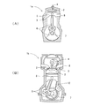
- FIG. 2A shows a two-stroke engine which is an embodiment of an internal combustion engine according to the present invention.
- the internal combustion engine 1a includes a fuel intake 3 for taking oxyhydrogen gas as fuel into the combustion chamber 2, and ignition for igniting the oxyhydrogen gas in the combustion chamber 2 at a predetermined timing.
- a motion conversion mechanism 6 comprising a plug 4, a piston 5 that reciprocates up and down in response to pressure changes in the combustion chamber 2 before and after ignition, and a crankshaft that converts the reciprocating motion of the piston 5 into the rotational motion of the output shaft 7.
- the fuel intake 3 can be, for example, a direct injection method in which oxyhydrogen gas is directly injected into the combustion chamber 2. Further, when a conventional gasoline engine or gas engine is used as the internal combustion engine according to the present invention, the intake manifold (air intake port) is used as the fuel intake port 3, and the combustion chamber 2 has a negative pressure. A necessary amount of oxyhydrogen gas may be naturally taken into the combustion chamber 2.
- oxyhydrogen gas is taken into the combustion chamber 2 from the fuel intake port 3 while the piston 5 is lowered, and the oxyhydrogen gas is compressed by the rise of the piston 5. Thereafter, the compressed oxyhydrogen gas is ignited by the spark plug 4 and expands (pressure increases), and the piston 5 is pushed down. Then, the movement of the piston 5 is transmitted to the output shaft 7 via the motion conversion mechanism 6, and the output shaft 7 rotates. The expanded oxyhydrogen gas is discharged from the discharge port 8 as water vapor or water.
- FIG. 2B shows a four-stroke engine which is an embodiment of the internal combustion engine according to the present invention.
- the internal combustion engine 1b includes a fuel intake port 3 for taking oxyhydrogen gas as fuel into the combustion chamber 2, a spark plug 4, a piston 5, a motion conversion mechanism 6, and an output.
- a shaft 7 and a discharge port 8 are provided.
- the internal combustion engine 1b includes a discharge valve 9 for adjusting the amount of gas discharged from the combustion chamber 2 through the discharge port 8, and a timing belt 10 that links the movement of the piston 5 and the opening / closing operation of the discharge valve 9.
- the fuel intake 3 may be a direct injection system in which oxyhydrogen gas is directly injected into the combustion chamber 2.
- a fuel intake valve (not shown) that opens and closes in conjunction with the movement of the piston 5 is provided between the fuel intake 3 and the combustion chamber 2, and corresponds to the discharge valve 9 in FIG. Thereby, the amount of oxyhydrogen gas taken into the combustion chamber 2 through the fuel intake 3 may be adjusted.
- the oxyhydrogen gas is taken into the combustion chamber 2 by the injection from the fuel intake port 3, and when the piston 5 is raised, the oxyhydrogen gas in the combustion chamber 2 is compressed.
- the compressed oxyhydrogen gas is ignited by the spark plug 4 and expands (pressure increases), and the piston 5 is pushed down.
- the discharge valve 9 opens and the oxyhydrogen gas in the combustion chamber 2 is discharged as water vapor or water.
- the movement of the piston 5 is transmitted to the output shaft 7 via the motion conversion mechanism 6, and the output shaft 7 rotates.
- the internal combustion engines 1a and 1b shown in FIGS. 2 (A) and 2 (B) do not necessarily stop the piston 5 at the top dead center when the operation is stopped, but in the space formed in the cylinder upper part (combustion chamber 2). Air may accumulate. For this reason, at the time of starting, a mixed gas of newly taken oxyhydrogen gas and accumulated air is compressed and ignited, and implosion can occur. When implosion occurs, explosion sounds occur in the engine, which is harsh. In order to prevent this implosion, (1) the intake of oxyhydrogen gas is stopped until the air accumulated in the combustion chamber 2 is discharged, or (2) the oxyhydrogen gas is ignited without ignition. It is necessary to discharge the mixed gas with air.
- the fuel intake port 3 may be a valve that opens and closes according to the amount of fuel supply pressure.
- This valve opens when the fuel supply pressure exceeds a predetermined pressure, and allows the fuel (oxyhydrogen gas) taken into the combustion chamber 2 to pass therethrough.
- this valve is designed not to be opened by the negative pressure or explosion of the combustion chamber 2, and serves as a check valve and a safety valve. By using this valve and setting the fuel supply pressure at a low level for a certain period after starting, oxyhydrogen gas is taken in before the air is discharged, and implosion can be prevented.
- this valve may be opened and closed under computer control.
- the ignition plug 4 may be controlled not to operate for a certain period after the start.
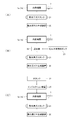
- FIG. 3 is a block diagram showing the internal combustion engine and its peripheral devices according to the present invention.
- the internal combustion engine 1a (1b) is supplied with the oxyhydrogen gas generated by the oxyhydrogen gas generator 20, and an oxyhydrogen gas tank 21 is provided between the oxyhydrogen gas tanks. 21 may temporarily store oxyhydrogen gas.
- the oxyhydrogen gas generator 20 can generate oxyhydrogen gas that does not return to water even when compressed at high pressure. Is preferred. In this regard, some oxyhydrogen gases in the early stages of research need to be noted because some of them return to water at about several atmospheres.
- a mixer 22 such as a carburetor may be provided between the oxyhydrogen gas generator 20 (oxyhydrogen gas tank 21) and the internal combustion engine 1a (1b).
- the mixed gas of the oxyhydrogen gas from the oxyhydrogen gas generator 20 and the fossil-derived fuel from the fossil-derived fuel tank 23 can be taken into the internal combustion engine 1a (1b) as fuel.
- carbon dioxide and nitrogen oxides are generated according to the ratio of the fossil-derived fuel contained in the mixed gas, but by using together with a fossil-derived fuel that is relatively easily available, oxyhydrogen The combustion efficiency of oxyhydrogen gas can be increased while suppressing the amount of gas used.
- the combustion efficiency of the fossil-derived fuel can be increased, and the fuel efficiency can be improved and the discharged carbon dioxide and nitrogen oxides can be reduced. That is, according to the embodiment shown in FIG. 3B, the internal combustion engine 1a (1b) can be stably operated.
- fossil fuels are just an example of existing fuels. Even if hydrogen is used instead of the fossil-derived fuel, the combustion efficiency of the oxyhydrogen gas can be increased while suppressing the amount of oxyhydrogen gas used.
- a water tank 24 and an injection device 25 may be further provided, and nano-level mist-like water may be injected into the combustion chamber 2.
- the atomized water is injected from a water injection port (not shown) provided in the combustion chamber 2 at the same timing as the intake of the oxyhydrogen gas.
- the mist water is burned together with the oxyhydrogen gas, and the volume of the water is increased by about 1700 times by the steam explosion, so that the pressure change in the combustion chamber 2 before and after the ignition becomes larger.
- a large amount of energy can be taken out, and the amount of oxyhydrogen gas used can be reduced as in the case of using a fossil fuel.
- FIG. 4 is a gas turbine which is an embodiment of the external combustion engine according to the present invention.
- the external combustion engine 1c compresses the oxyhydrogen gas taken in by rotating at high speed around the output shaft 18 and the fuel intake 11 for taking in oxyhydrogen gas as fuel.
- the compressor 12 sent to the combustion chamber 13, the spark plug 14 that ignites the compressed oxyhydrogen gas in the combustion chamber 13 to convert it into high-temperature gas, and the high-temperature gas discharged from the combustion chamber 13 vigorously hits the blades And a turbine 17 that rotates at high speed around the output shaft 18.
- the external combustion engine 1c also includes a regenerator 19 for increasing the efficiency.
- the compressed oxyhydrogen gas becomes a high-temperature gas composed of water vapor in the combustion chamber 13, and the turbine 17 rotates at high speed by the energy of the high-temperature gas.
- the compressor 12 coaxially connected to the turbine 17 via the output shaft 18 rotates at high speed, and the compressed oxyhydrogen gas is continuously sent to the combustion chamber 13.
- the taken oxyhydrogen gas is finally discharged as water vapor or water.
- the external combustion engine 1c may further include a fuel injection port 15 or a water injection port 16. If the existing fuel injected from the fuel injection port 15 or the nano level mist of water injected from the water injection port 16 and the compressed oxyhydrogen gas are burned together, the internal combustion engines 1a and 1b Similar effects can be obtained.
- the oxyhydrogen gas can be supplied from, for example, the oxyhydrogen gas generator 20 or the oxyhydrogen gas tank 21 shown in FIG. 3, and the mist-like water can be supplied from, for example, the water tank 24 shown in FIG.
- the fuel can be injected into the combustion chamber 13 using the injection device 25.
- the existing fuel can be injected into the combustion chamber 13 by various methods used in conventional gas turbines.
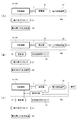
- FIG. 5A is a block diagram of a power generation system using an internal combustion engine according to the present invention and its peripheral devices.
- the power generation system 30a includes at least an internal combustion engine 1a (1b) and a generator 31 connected to the output shaft 7.
- the generator 31 when the output shaft 7 of the internal combustion engine 1a (1b) is rotated by supplying the oxyhydrogen gas, the generator 31 generates electric power accordingly.
- a power conversion device 32 may be provided on the output side of the generator 31, and the power from the generator 31 may be converted into desired power and output.
- the power conversion device 32 include a DC-AC inverter device that converts DC 12V DC power output from the generator 31 into AC 100V AC power, a power output from the generator 31 or a commercial power source.
- a device including an inverter for adjusting to the frequency of the above is used.
- the internal combustion engine 1a (1b) is supplied with a mixed gas of oxyhydrogen gas and fossil-derived fuel (existing fuel) mixed by the mixer 22. Also good.
- the mixer 22 is for mixing two kinds of gases at a desired ratio, and can be composed of a pressure regulator, a shut-off valve, a zero governor, a mixer, and the like.
- the power generation system includes a control unit 33 including a computer and various sensors as in a power generation system 30c shown in FIG.
- the control means 33 detects the output voltage or output current (the magnitude of the power load) of the generator 31 or the power converter 32, and the amount of oxyhydrogen gas or mixed gas taken into the combustion chamber 2 based on the detection result, , Change the ignition timing.
- FIG. 6A is a block diagram of a power generation system using the external combustion engine according to the present invention and its peripheral devices.
- the power generation system 30d includes at least the external combustion engine 1c and a generator 31 connected to the output shaft 18 thereof.
- the generator 31 when the output shaft 18 of the external combustion engine 1c rotates, the generator 31 generates electric power accordingly.
- the power generation system 30 d may include a power conversion device 32 on the output side of the generator 31.
- power generation using the external combustion engine 1c configured such that mist-like water is injected into the combustion chamber 13 by the water tank 24 and the injection device 25.
- a power generation system 30f configured such that the amount of sprayed water and the timing of ignition are controlled by the system 30e and the control means 33 can be considered.
- Each of the power generation systems 30a to 30f may further include a secondary battery (not shown) that can be charged with a DC voltage output from the generator 31 between the generator 31 and the power conversion device 32. .
- a secondary battery (not shown) that can be charged with a DC voltage output from the generator 31 between the generator 31 and the power conversion device 32.
- Ignition timing is represented by the rotation angle of the crankshaft (motion conversion mechanism 6) based on the state where the piston 5 is at the top dead center. If the ignition timing is too early, combustion proceeds before the piston 5 reaches the top dead center, that is, before the oxyhydrogen gas is sufficiently compressed, and the piston 5 is pushed down. On the other hand, if the ignition timing is too late, the oxyhydrogen gas burns after the piston 5 starts to descend, and therefore the pressure change due to the expansion cannot be fully utilized. From this point of view, in this experiment, the ignition timing was fixed at 25 ° before top dead center (BTDC).
- oxyhydrogen gas has a slower combustion rate than fossil fuels such as gasoline, it is considered preferable to set the ignition timing earlier than when fossil fuels are used.
- Compressive pressure In the above experiment, in order to rotate normally even at low speed, the pressure was not less than 5 kgf / cm 2 .
- Fuel supply pressure In the said experiment, the supply pressure of oxyhydrogen gas was 0.2 MPa.
- Power converter In the above experiment, a self-excited inverter was used.
Landscapes
- Engineering & Computer Science (AREA)
- Chemical & Material Sciences (AREA)
- Combustion & Propulsion (AREA)
- Mechanical Engineering (AREA)
- General Engineering & Computer Science (AREA)
- Sustainable Energy (AREA)
- Oil, Petroleum & Natural Gas (AREA)
- Physics & Mathematics (AREA)
- Life Sciences & Earth Sciences (AREA)
- Sustainable Development (AREA)
- Thermal Sciences (AREA)
- General Chemical & Material Sciences (AREA)
- Chemical Kinetics & Catalysis (AREA)
- High Energy & Nuclear Physics (AREA)
- Output Control And Ontrol Of Special Type Engine (AREA)
- Combustion Methods Of Internal-Combustion Engines (AREA)
- Electrical Control Of Air Or Fuel Supplied To Internal-Combustion Engine (AREA)
- Electrical Control Of Ignition Timing (AREA)
- Control Of Vehicle Engines Or Engines For Specific Uses (AREA)
- Combined Controls Of Internal Combustion Engines (AREA)
Abstract
Description
・2C8H18+25O2→18H2O+16CO2
・C3H8+5O2→4H2O+3CO2
の反応式に示されるように、それぞれ、16CO2、3CO2の二酸化炭素が発生する。また、空気の70%以上は窒素なので、混合ガスを燃焼させると、上記二酸化炭素とともに窒素酸化物(NOX)も発生する。 In the internal combustion engine and the external combustion engine (hereinafter collectively referred to as “heat engine”), not less than carbon dioxide (CO 2 ) is generated when the mixed gas is burned. For example, if the fossil fuel is gasoline or propane gas,
・ 2C 8 H 18 + 25O 2 → 18H 2 O + 16CO 2
・ C 3 H 8 + 5O 2 → 4H 2 O + 3CO 2
As shown in the reaction formula, 16CO 2 and 3CO 2 of carbon dioxide are generated, respectively. Further, since 70% or more of the air is nitrogen, when the mixed gas is burned, nitrogen oxides (NO x ) are also generated together with the carbon dioxide.
ここで、本明細書における“既存燃料”の語は従来の熱機関で一般的に使用されている燃料を意味するものとする。例えば、“既存燃料”には、ガソリン、重油、軽油、プロパンガス、天然ガス、灯油(ケロシン)、ジェット燃料、ロケット燃料等の化石由来燃料の他、水素等が含まれる。酸水素ガスと化石由来燃料とを混合した混合ガスを用いると、化石由来燃料の混合比に応じて二酸化炭素や窒素酸化物が発生してしまうが、比較的入手が容易な化石由来燃料を併用することにより、酸水素ガスの使用量を抑えつつ、酸水素ガスの燃焼効率を高めることができる。また、化石由来燃料の混合比率が高い場合でも、化石由来燃料の燃焼効率を上げることができ、燃費改善や、排出される二酸化炭素および窒素酸化物の削減ができる。水素との混合ガスを燃料とした場合も、酸水素ガスの使用量を抑えつつ、酸水素ガスの燃焼効率を高めることができる。したがって、この構成によれば、安定的に熱機関を稼動させることができる。この作用効果は、酸水素ガスを安定供給するためのインフラが整うまでの普及過渡期において、特に有益だと考えられる。 In the heat engine according to the first aspect of the invention, the fuel can be a mixed gas of oxyhydrogen gas and existing fuel.
Here, the term “existing fuel” in this specification means a fuel generally used in a conventional heat engine. For example, the “existing fuel” includes fossil fuels such as gasoline, heavy oil, light oil, propane gas, natural gas, kerosene, jet fuel, and rocket fuel, as well as hydrogen. When using a mixed gas in which oxyhydrogen gas and fossil-derived fuel are mixed, carbon dioxide and nitrogen oxides are generated depending on the mixing ratio of fossil-derived fuel. By doing so, the combustion efficiency of oxyhydrogen gas can be improved, suppressing the usage-amount of oxyhydrogen gas. Moreover, even when the mixing ratio of the fossil-derived fuel is high, the combustion efficiency of the fossil-derived fuel can be increased, and the fuel efficiency can be improved and the discharged carbon dioxide and nitrogen oxides can be reduced. Even when a mixed gas with hydrogen is used as a fuel, the combustion efficiency of oxyhydrogen gas can be increased while suppressing the amount of oxyhydrogen gas used. Therefore, according to this configuration, the heat engine can be operated stably. This effect is considered to be particularly beneficial during the transition period until the infrastructure for stable supply of oxyhydrogen gas is established.
この構成によれば、酸水素ガスと一緒に燃焼させられた霧状の水の体積が水蒸気爆発により約1700倍になるので、点火前後における燃焼室内の圧力変化が大きくなってより大きなエネルギーを取り出すことが可能になるとともに、既存燃料を併用した場合と同様に、酸水素ガスの使用量を抑えることができる。 The heat engine according to the first aspect of the present invention may further include a water injection port for injecting nano-level mist-like water into the combustion chamber.
According to this configuration, the volume of the mist-like water combusted with the oxyhydrogen gas is increased by about 1700 times due to the steam explosion, so that the pressure change in the combustion chamber before and after the ignition becomes large, and more energy is taken out. This makes it possible to reduce the amount of oxyhydrogen gas used, as in the case of using an existing fuel together.
この構成によれば、燃焼室内に溜まっている空気と新たに取り込まれた酸水素ガスの混合ガスが燃焼させられることにより起こる始動直後の爆縮を防ぐことができる。 The heat engine according to the first aspect of the present invention is preferably configured so that the fuel intake port does not take fuel into the combustion chamber or the spark plug does not ignite the fuel for a certain period after startup.
According to this configuration, it is possible to prevent implosion immediately after starting, which is caused by burning the mixed gas of the air accumulated in the combustion chamber and the newly taken oxyhydrogen gas.
この構成によれば、第1発明に係る熱機関(内燃機関)と同様に、酸水素ガスの使用量を抑えつつ酸水素ガスの燃焼効率を高めたり、霧状の水が水蒸気爆発することを利用してより大きなエネルギーを取り出したりすることができる。 The heat engine according to the second aspect of the present invention may further include a fuel injection port for injecting existing fuel into the combustion chamber and a water injection port for injecting nano-level mist-like water into the combustion chamber.
According to this configuration, similarly to the heat engine (internal combustion engine) according to the first invention, the combustion efficiency of oxyhydrogen gas is increased while suppressing the amount of oxyhydrogen gas used, or the mist-like water is subjected to steam explosion. It can be used to extract more energy.
図2(A)は、本発明に係る内燃機関の一実施形態である2ストロークエンジンである。同図に示すように、内燃機関1aは、燃焼室2内に燃料としての酸水素ガスを取り込むための燃料取込口3と、所定のタイミングで燃焼室2内の酸水素ガスに点火する点火プラグ4と、点火前後における燃焼室2内の圧力変化に応じて上下に往復運動するピストン5と、ピストン5の往復運動を出力軸7の回転運動に変換するクランクシャフト等からなる運動変換機構6とを備えている。 [Configuration of internal combustion engine]
FIG. 2A shows a two-stroke engine which is an embodiment of an internal combustion engine according to the present invention. As shown in the figure, the
図4は、本発明に係る外燃機関の一実施形態であるガスタービンである。同図に示すように、外燃機関1cは、燃料としての酸水素ガスを取り込むための燃料取込口11と、出力軸18回りに高速回転することにより取り込まれた酸水素ガスを圧縮して燃焼室13に送る圧縮機12と、燃焼室13内の圧縮された酸水素ガスに点火して高温ガス化する点火プラグ14と、燃焼室13から排出された高温ガスが勢いよく羽根に当たることにより出力軸18回りに高速回転するタービン17とを備えている。また、外燃機関1cは、効率を高めるための再生器19も備えている。 [Configuration of external combustion engine]
FIG. 4 is a gas turbine which is an embodiment of the external combustion engine according to the present invention. As shown in the figure, the
図5(A)は、本発明に係る内燃機関を用いた発電システムおよびその周辺装置のブロック図である。発電システム30aは、少なくとも内燃機関1a(1b)とその出力軸7に接続された発電機31とを備えている。この発電システム30aでは、酸水素ガスが供給されることにより内燃機関1a(1b)の出力軸7が回転すると、それに応じて発電機31が電力を発生する。 [Configuration of power generation system]
FIG. 5A is a block diagram of a power generation system using an internal combustion engine according to the present invention and its peripheral devices. The
続いて、空気供給口を塞いだ市販の空冷4ストロークOHVエンジン(三菱重工製“GM82PN”)に酸水素ガスを供給して発電を行った実験結果について説明する。実験条件は以下の通りである。 [Experimental result]
Subsequently, an experimental result of generating power by supplying oxyhydrogen gas to a commercially available air-cooled 4-stroke OHV engine (“GM82PN” manufactured by Mitsubishi Heavy Industries) with the air supply port closed will be described. The experimental conditions are as follows.
点火タイミングは、ピストン5が上死点にある状態を基準としたクランクシャフト(運動変換機構6)の回転角度で表される。点火タイミングが早すぎるとピストン5が上死点に達する前、すなわち酸水素ガスが充分圧縮される前に燃焼が進み、ピストン5が押し下げられるため、無駄が生じる。一方、点火タイミングが遅すぎると、ピストン5が下降し始めてから酸水素ガスが燃焼するので、その膨張による圧力変化を活かしきれない。このような観点から、本実験では、点火タイミングを上死点前(BTDC)25°固定とした。なお、ガソリン等の化石由来燃料に比べて、酸水素ガスは燃焼速度が遅いため、点火タイミングは化石由来燃料を用いる場合よりも早めに設定するのが好ましいと考えられる。
(2)圧縮圧力
上記実験では、低速でも正常回転させるために5kgf/cm2を下回らないようにした。
(3)燃料供給圧力
上記実験では、酸水素ガスの供給圧力を0.2MPaとした。
(4)電力変換装置
上記実験では、自己励磁式のインバータを使用した。 (1) Ignition timing Ignition timing is represented by the rotation angle of the crankshaft (motion conversion mechanism 6) based on the state where the
(2) Compressive pressure In the above experiment, in order to rotate normally even at low speed, the pressure was not less than 5 kgf / cm 2 .
(3) Fuel supply pressure In the said experiment, the supply pressure of oxyhydrogen gas was 0.2 MPa.
(4) Power converter In the above experiment, a self-excited inverter was used.
1c 外燃機関
2 燃焼室
3 燃料取込口
4 点火プラグ
5 ピストン
6 運動変換機構
7 出力軸
8 排出口
9 排出バルブ
10 タイミングベルト
11 燃料取込口
12 圧縮機
13 燃焼室
14 点火プラグ
15 燃料噴射口
16 水噴射口
17 タービン
18 出力軸
19 再生器
20 酸水素ガス生成装置
21 酸水素ガスタンク
22 混合機
23 化石由来燃料タンク
24 水タンク
25 インジェクション装置
30a~30f 発電システム
31 発電機
32 電力変換装置
33 制御手段 1a, 1b
Claims (11)
- 燃焼室内に燃料としての酸水素ガスを取り込むための燃料取込口と、
前記燃焼室内の前記燃料に点火する点火プラグと、
点火前後における前記燃焼室内の圧力変化に応じて運動するピストンと、
前記ピストンの運動を出力軸の回転運動に変える運動変換機構と、
を備えた内燃機関であることを特徴とする熱機関。 A fuel inlet for taking oxyhydrogen gas as fuel into the combustion chamber;
A spark plug for igniting the fuel in the combustion chamber;
A piston that moves in response to a pressure change in the combustion chamber before and after ignition;
A motion conversion mechanism that converts the motion of the piston into a rotational motion of the output shaft;
An internal combustion engine provided with a heat engine. - 前記燃料は、前記酸水素ガスと既存燃料との混合ガスであることを特徴とする請求項1に記載の熱機関。 The heat engine according to claim 1, wherein the fuel is a mixed gas of the oxyhydrogen gas and an existing fuel.
- 前記燃焼室内にナノレベルの霧状の水を噴射する水噴射口をさらに備えたことを特徴とする請求項1に記載の熱機関。 The heat engine according to claim 1, further comprising a water injection port for injecting nano-level mist water into the combustion chamber.
- 前記燃料取込口は、ダイレクトインジェクション方式により前記燃料を前記燃焼室内に直接噴射することを特徴とする請求項1から3のいずれかに記載の熱機関。 The heat engine according to any one of claims 1 to 3, wherein the fuel intake port directly injects the fuel into the combustion chamber by a direct injection method.
- 前記燃料取込口は、逆止弁および安全弁の役割を果たすバルブであることを特徴とする請求項1~4のいずれかに記載の熱機関。 The heat engine according to any one of claims 1 to 4, wherein the fuel intake port is a valve that functions as a check valve and a safety valve.
- 始動後、一定期間の間は、前記燃料取込口が前記燃料を前記燃焼室内に取り込まないか、または前記点火プラグが前記燃料に点火しないことを特徴とする請求項1~5のいずれかに記載の熱機関。 6. The fuel intake according to claim 1, wherein the fuel intake port does not take in the fuel into the combustion chamber or the spark plug does not ignite the fuel for a certain period after startup. The listed heat engine.
- 燃料としての酸水素ガスを取り込むための燃料取込口と、
出力軸回りに回転することにより取り込まれた前記燃料を圧縮して燃焼室に送る圧縮機と、
前記燃焼室内の圧縮された前記燃料に点火して高温ガス化する点火プラグと、
前記燃焼室から排出された前記高温ガスにより前記出力軸回りに回転させられるタービンと、
を備えた外燃機関であることを特徴とする熱機関。 A fuel inlet for taking in oxyhydrogen gas as fuel;
A compressor that compresses the fuel taken in by rotating around the output shaft and sends it to the combustion chamber;
A spark plug for igniting the compressed fuel in the combustion chamber to gasify it at a high temperature;
A turbine rotated around the output shaft by the hot gas discharged from the combustion chamber;
An external combustion engine equipped with a heat engine. - 前記燃焼室内に既存燃料を噴射する燃料噴射口をさらに備えたことを特徴とする請求項7に記載の熱機関。 The heat engine according to claim 7, further comprising a fuel injection port for injecting existing fuel into the combustion chamber.
- 前記燃焼室内にナノレベルの霧状の水を噴射する水噴射口をさらに備えたことを特徴とする請求項7に記載の熱機関。 The heat engine according to claim 7, further comprising a water injection port for injecting nano-level mist water into the combustion chamber.
- 請求項1から9のいずれかに記載の熱機関と、
前記熱機関の出力軸に接続された発電機と、
を備えたことを特徴とする発電システム。 A heat engine according to any one of claims 1 to 9,
A generator connected to the output shaft of the heat engine;
A power generation system comprising: - 前記発電機が発生させた第1電力を所望の第2電力に変換する電力変換装置と、
前記発電機または前記電力変換装置の出力電圧もしくは出力電流または出力電圧と出力電圧の双方を検出し、検出した結果に基づいて取り込む前記燃料の量および前記点火のタイミングを変化させる制御手段と、
をさらに備えたことを特徴とする請求項10に記載の発電システム。 A power converter that converts the first power generated by the generator into a desired second power;
Control means for detecting the output voltage or output current of the generator or the power converter or both the output voltage and the output voltage, and changing the amount of the fuel to be taken in and the ignition timing based on the detected result;
The power generation system according to claim 10, further comprising:
Priority Applications (4)
| Application Number | Priority Date | Filing Date | Title |
|---|---|---|---|
| CN201180017297.7A CN102844544B (en) | 2010-04-02 | 2011-04-04 | Heat engine |
| JP2012509652A JPWO2011125976A1 (en) | 2010-04-02 | 2011-04-04 | Heat engine and power generation system using the heat engine |
| US13/636,848 US20130014728A1 (en) | 2010-04-02 | 2011-04-04 | Heat engine and power generation system using the heat engine |
| EP11765876A EP2554821A1 (en) | 2010-04-02 | 2011-04-04 | Heat engine and power generation system using the heat engine |
Applications Claiming Priority (4)
| Application Number | Priority Date | Filing Date | Title |
|---|---|---|---|
| JP2010086090 | 2010-04-02 | ||
| JP2010-086090 | 2010-04-02 | ||
| JP2010-285400 | 2010-12-22 | ||
| JP2010285400 | 2010-12-22 |
Publications (1)
| Publication Number | Publication Date |
|---|---|
| WO2011125976A1 true WO2011125976A1 (en) | 2011-10-13 |
Family
ID=44762911
Family Applications (1)
| Application Number | Title | Priority Date | Filing Date |
|---|---|---|---|
| PCT/JP2011/058518 WO2011125976A1 (en) | 2010-04-02 | 2011-04-04 | Heat engine and power generation system using the heat engine |
Country Status (5)
| Country | Link |
|---|---|
| US (1) | US20130014728A1 (en) |
| EP (1) | EP2554821A1 (en) |
| JP (1) | JPWO2011125976A1 (en) |
| CN (1) | CN102844544B (en) |
| WO (1) | WO2011125976A1 (en) |
Cited By (7)
| Publication number | Priority date | Publication date | Assignee | Title |
|---|---|---|---|---|
| WO2014148192A1 (en) * | 2013-03-19 | 2014-09-25 | 三菱重工業株式会社 | Exhaust gas control device of gas engine |
| JP2016014384A (en) * | 2014-07-03 | 2016-01-28 | 博信 ▲浜▼口 | Perfect combustion internal combustion engine with air motor assist |
| JP2016540930A (en) * | 2013-10-30 | 2016-12-28 | ジテンダラ クマー バーカーBARTHAKUR, Jitendra Kumar | Convergent heat generation engine for explosion systems with safety devices such as safe pipe systems |
| JP2017203388A (en) * | 2016-05-09 | 2017-11-16 | 義夫 大河 | Liquid fuel reduction device used in diesel engine |
| JP2018526580A (en) * | 2015-07-29 | 2018-09-13 | フュールセーブ ゲーエムベーハー | Ship propulsion system and operation method of ship propulsion system |
| WO2018173116A1 (en) * | 2017-03-21 | 2018-09-27 | 欣四郎 近藤 | Power generation device and power generation method therefor |
| JP2021092224A (en) * | 2019-12-03 | 2021-06-17 | 寛治 泉 | Engine burning hydrogen and oxygen and also producing hydrogen and oxygen |
Citations (8)
| Publication number | Priority date | Publication date | Assignee | Title |
|---|---|---|---|---|
| JPH0286923A (en) * | 1988-09-22 | 1990-03-27 | Toyota Autom Loom Works Ltd | Starting method for hydrogen fueled engine |
| JPH05321764A (en) * | 1992-05-18 | 1993-12-07 | Mazda Motor Corp | Fuel supplying device of gas fuel engine |
| JP2001164998A (en) * | 1999-11-10 | 2001-06-19 | Waertsilae Nsd Schweiz Ag | Method for operating four-stroke diesel engine |
| JP2001295705A (en) * | 2000-04-17 | 2001-10-26 | Takeshi Hatanaka | Combustion accelerating device for engine |
| JP2003206706A (en) * | 2002-01-17 | 2003-07-25 | Zetto:Kk | Power generation system |
| JP2003254012A (en) * | 2002-03-06 | 2003-09-10 | Denso Corp | Steam generator |
| JP3975467B2 (en) | 2001-05-02 | 2007-09-12 | 日本テクノ株式会社 | Hydrogen-oxygen gas generator and hydrogen-oxygen gas generation method using the same |
| JP2009121404A (en) * | 2007-11-16 | 2009-06-04 | Mazda Motor Corp | Cogeneration system using hydrogen engine |
Family Cites Families (23)
| Publication number | Priority date | Publication date | Assignee | Title |
|---|---|---|---|---|
| DE3146434A1 (en) * | 1981-11-24 | 1983-06-01 | Hohl, Adolf, 7180 Crailsheim | Oxyhydrogen gas from decomposed water |
| US5293857A (en) * | 1990-11-02 | 1994-03-15 | Stanley Meyer | Hydrogen gas fuel and management system for an internal combustion engine utilizing hydrogen gas fuel |
| JPH05256160A (en) * | 1992-03-11 | 1993-10-05 | Mitsubishi Heavy Ind Ltd | Hydrogen-fuel engine system |
| US6019077A (en) * | 1998-06-29 | 2000-02-01 | Gorokhovsky; Vladimir I. | Spark plug for internal combustion engine |
| JP2000028110A (en) * | 1998-07-10 | 2000-01-25 | Kazutoshi Sakuta | Hydrogen generation device and combustion method |
| US20070151846A1 (en) * | 2001-04-04 | 2007-07-05 | Hydrogen Technology Applications, Inc. | Apparatus and method for the conversion of water into a clean burning combustible gas for use as an additive with other forms of fuels |
| CN100363600C (en) * | 2005-06-10 | 2008-01-23 | 缪博华 | Hydrogen engine |
| AT503126B1 (en) * | 2006-06-28 | 2007-08-15 | Figl Gerhard | Internal combustion engine burning hydrogen and oxygen, has separate injectors for hydrogen and oxygen introduction, with electrically-operated valves and thermolytic catalyst |
| JP2008020167A (en) * | 2006-07-14 | 2008-01-31 | Oyo Denki Kk | Boiler device and its control method |
| RO122556B1 (en) * | 2006-07-28 | 2009-08-28 | J. Klein Dennis | Process for using poor mixtures |
| JP4586780B2 (en) * | 2006-09-07 | 2010-11-24 | トヨタ自動車株式会社 | Working gas circulation engine |
| US8479690B2 (en) * | 2007-03-16 | 2013-07-09 | Maro Performance Group, Llc | Advanced internal combustion engine |
| FR2931844B1 (en) * | 2008-06-02 | 2013-11-01 | Alex Hr Roustaei | SYSTEMS FOR THE PRODUCTION OF ON-DEMAND ENERGY AS A SOURCE ALONE OR IN ASSISTANCE WITH OTHER SOURCES OF ENERGY IN THE FIELD OF TRANSPORT OR HABITAT. |
| US20110108000A1 (en) * | 2008-06-26 | 2011-05-12 | Williams Tudor D | Apparatus and method for operating an engine with non-fuel fluid injection |
| US20100038236A1 (en) * | 2008-08-18 | 2010-02-18 | Alex Rivera | Hydrogen-from-water on-demand supplemental vehicle fuel electrolyzer system |
| US8424496B2 (en) * | 2009-02-03 | 2013-04-23 | Ford Global Technologies, Llc | Methods and systems for starting a vehicle engine |
| US8109354B2 (en) * | 2009-02-13 | 2012-02-07 | Yu Chuan Technology Enterprise Co., Ltd. | Oxyhydrogen vehicle |
| US20100229839A1 (en) * | 2009-03-13 | 2010-09-16 | Fornarelli Jr Thomas | Hydrogen fuel enhancement system |
| US20100258510A1 (en) * | 2009-04-10 | 2010-10-14 | Applied Materials, Inc. | Methods and apparatus for treating effluent |
| US20100288212A1 (en) * | 2009-05-14 | 2010-11-18 | Norman Williams | On demand system for using water (HHO) as a sole fuel |
| US20100320083A1 (en) * | 2009-06-19 | 2010-12-23 | Roger Calvin Seratt | Hydrogen fuel generator |
| MY169591A (en) * | 2010-02-22 | 2019-04-22 | Univ Malaysia Pahang | Hydrogen gas fuel |
| US8714115B2 (en) * | 2010-04-09 | 2014-05-06 | Hydrogen Injection Technology, Inc. | Cylindrical hydrogen fuel generator having passive tubular cells |
-
2011
- 2011-04-04 JP JP2012509652A patent/JPWO2011125976A1/en active Pending
- 2011-04-04 CN CN201180017297.7A patent/CN102844544B/en not_active Expired - Fee Related
- 2011-04-04 WO PCT/JP2011/058518 patent/WO2011125976A1/en active Application Filing
- 2011-04-04 US US13/636,848 patent/US20130014728A1/en not_active Abandoned
- 2011-04-04 EP EP11765876A patent/EP2554821A1/en not_active Withdrawn
Patent Citations (8)
| Publication number | Priority date | Publication date | Assignee | Title |
|---|---|---|---|---|
| JPH0286923A (en) * | 1988-09-22 | 1990-03-27 | Toyota Autom Loom Works Ltd | Starting method for hydrogen fueled engine |
| JPH05321764A (en) * | 1992-05-18 | 1993-12-07 | Mazda Motor Corp | Fuel supplying device of gas fuel engine |
| JP2001164998A (en) * | 1999-11-10 | 2001-06-19 | Waertsilae Nsd Schweiz Ag | Method for operating four-stroke diesel engine |
| JP2001295705A (en) * | 2000-04-17 | 2001-10-26 | Takeshi Hatanaka | Combustion accelerating device for engine |
| JP3975467B2 (en) | 2001-05-02 | 2007-09-12 | 日本テクノ株式会社 | Hydrogen-oxygen gas generator and hydrogen-oxygen gas generation method using the same |
| JP2003206706A (en) * | 2002-01-17 | 2003-07-25 | Zetto:Kk | Power generation system |
| JP2003254012A (en) * | 2002-03-06 | 2003-09-10 | Denso Corp | Steam generator |
| JP2009121404A (en) * | 2007-11-16 | 2009-06-04 | Mazda Motor Corp | Cogeneration system using hydrogen engine |
Cited By (11)
| Publication number | Priority date | Publication date | Assignee | Title |
|---|---|---|---|---|
| WO2014148192A1 (en) * | 2013-03-19 | 2014-09-25 | 三菱重工業株式会社 | Exhaust gas control device of gas engine |
| JP2014181614A (en) * | 2013-03-19 | 2014-09-29 | Mitsubishi Heavy Ind Ltd | Exhaust gas control device for gas engine |
| US9551285B2 (en) | 2013-03-19 | 2017-01-24 | Mitsubishi Heavy Industries, Ltd. | Exhaust gas control device of gas engine |
| JP2016540930A (en) * | 2013-10-30 | 2016-12-28 | ジテンダラ クマー バーカーBARTHAKUR, Jitendra Kumar | Convergent heat generation engine for explosion systems with safety devices such as safe pipe systems |
| JP2016014384A (en) * | 2014-07-03 | 2016-01-28 | 博信 ▲浜▼口 | Perfect combustion internal combustion engine with air motor assist |
| JP2018526580A (en) * | 2015-07-29 | 2018-09-13 | フュールセーブ ゲーエムベーハー | Ship propulsion system and operation method of ship propulsion system |
| JP2017203388A (en) * | 2016-05-09 | 2017-11-16 | 義夫 大河 | Liquid fuel reduction device used in diesel engine |
| WO2018173116A1 (en) * | 2017-03-21 | 2018-09-27 | 欣四郎 近藤 | Power generation device and power generation method therefor |
| JPWO2018173116A1 (en) * | 2017-03-21 | 2020-01-23 | 欣四郎 近藤 | Power generation device and power generation method thereof |
| JP2021092224A (en) * | 2019-12-03 | 2021-06-17 | 寛治 泉 | Engine burning hydrogen and oxygen and also producing hydrogen and oxygen |
| JP7004887B2 (en) | 2019-12-03 | 2022-02-07 | 寛治 泉 | An engine that burns hydrogen and oxygen. |
Also Published As
| Publication number | Publication date |
|---|---|
| CN102844544A (en) | 2012-12-26 |
| JPWO2011125976A1 (en) | 2013-07-11 |
| CN102844544B (en) | 2015-04-01 |
| US20130014728A1 (en) | 2013-01-17 |
| EP2554821A1 (en) | 2013-02-06 |
Similar Documents
| Publication | Publication Date | Title |
|---|---|---|
| WO2011125976A1 (en) | Heat engine and power generation system using the heat engine | |
| US10858990B2 (en) | Internal combustion steam engine | |
| US9404412B2 (en) | Two-stroke engine and four-stroke engine | |
| US20110108000A1 (en) | Apparatus and method for operating an engine with non-fuel fluid injection | |
| JP5833326B2 (en) | Injection device | |
| US9140181B2 (en) | Power-producing apparatus and method | |
| JP2023018060A (en) | Compression ignition internal combustion engine operated by ammonia and modification kit | |
| JP5939836B2 (en) | Sub-chamber engine and operation control method thereof | |
| CN114526150A (en) | Jet ignition hydrogen-oxygen internal combustion engine based on precombustion chamber and control method | |
| JP2892235B2 (en) | Cogeneration type gas engine | |
| US20070245734A1 (en) | Internal steam engine | |
| US20230203981A1 (en) | Gas exchange in internal combustion engines for increased efficiency | |
| JP7307293B1 (en) | Large turbocharged two-stroke uniflow crosshead compression ignition internal combustion engine and method of operation thereof | |
| JPH0486329A (en) | Monoatomic gas internal combustion engine | |
| WO1998003779A2 (en) | Engine having direct water injection during power stroke | |
| JP2918403B2 (en) | 6 stroke gas engine | |
| CN103967652A (en) | Piston ram self-ignition pulse-jet engine | |
| CN103410622A (en) | KR gasoline internal combustion engine | |
| KR20190135945A (en) | Exhaust gas recirculation system and ship including the same | |
| CN103993957A (en) | Efficient gasoline internal combustion engine | |
| JP2009156037A (en) | Hydrogen supply device | |
| JP2000274314A (en) | Engine and knocking suppressing method therefor | |
| CN103410612A (en) | High-efficiency diesel internal combustion engine | |
| CN103696858A (en) | Volume control circulation mode internal combustion engine |
Legal Events
| Date | Code | Title | Description |
|---|---|---|---|
| WWE | Wipo information: entry into national phase |
Ref document number: 201180017297.7 Country of ref document: CN |
|
| 121 | Ep: the epo has been informed by wipo that ep was designated in this application |
Ref document number: 11765876 Country of ref document: EP Kind code of ref document: A1 |
|
| DPE1 | Request for preliminary examination filed after expiration of 19th month from priority date (pct application filed from 20040101) | ||
| WWE | Wipo information: entry into national phase |
Ref document number: 13636848 Country of ref document: US |
|
| WWE | Wipo information: entry into national phase |
Ref document number: 2012509652 Country of ref document: JP |
|
| NENP | Non-entry into the national phase |
Ref country code: DE |
|
| WWE | Wipo information: entry into national phase |
Ref document number: 2011765876 Country of ref document: EP |