EP2977595B1 - Exhaust gas control device for a gas engine - Google Patents
Exhaust gas control device for a gas engine Download PDFInfo
- Publication number
- EP2977595B1 EP2977595B1 EP14767698.5A EP14767698A EP2977595B1 EP 2977595 B1 EP2977595 B1 EP 2977595B1 EP 14767698 A EP14767698 A EP 14767698A EP 2977595 B1 EP2977595 B1 EP 2977595B1
- Authority
- EP
- European Patent Office
- Prior art keywords
- operation mode
- nox
- gas
- air
- fuel
- Prior art date
- Legal status (The legal status is an assumption and is not a legal conclusion. Google has not performed a legal analysis and makes no representation as to the accuracy of the status listed.)
- Active
Links
- 239000007789 gas Substances 0.000 claims description 103
- 239000000446 fuel Substances 0.000 claims description 76
- 230000009467 reduction Effects 0.000 claims description 56
- 238000002485 combustion reaction Methods 0.000 claims description 27
- 239000002737 fuel gas Substances 0.000 claims description 26
- 238000002347 injection Methods 0.000 claims description 16
- 239000007924 injection Substances 0.000 claims description 16
- MWUXSHHQAYIFBG-UHFFFAOYSA-N Nitric oxide Chemical compound O=[N] MWUXSHHQAYIFBG-UHFFFAOYSA-N 0.000 description 423
- 239000003570 air Substances 0.000 description 39
- 230000007613 environmental effect Effects 0.000 description 10
- 239000002699 waste material Substances 0.000 description 9
- 238000010248 power generation Methods 0.000 description 8
- 230000000694 effects Effects 0.000 description 7
- 238000012423 maintenance Methods 0.000 description 7
- 239000012080 ambient air Substances 0.000 description 6
- 230000008859 change Effects 0.000 description 6
- 238000013459 approach Methods 0.000 description 5
- 230000006866 deterioration Effects 0.000 description 5
- 238000000034 method Methods 0.000 description 5
- 230000008569 process Effects 0.000 description 5
- 238000010586 diagram Methods 0.000 description 4
- 239000007788 liquid Substances 0.000 description 4
- 238000005259 measurement Methods 0.000 description 4
- 230000002093 peripheral effect Effects 0.000 description 4
- 238000011144 upstream manufacturing Methods 0.000 description 4
- 238000004519 manufacturing process Methods 0.000 description 3
- 239000000203 mixture Substances 0.000 description 3
- 230000007704 transition Effects 0.000 description 3
- 238000009841 combustion method Methods 0.000 description 2
- 238000001514 detection method Methods 0.000 description 2
- 238000009434 installation Methods 0.000 description 2
- 239000000791 photochemical oxidant Substances 0.000 description 2
- 230000004044 response Effects 0.000 description 2
- 239000000853 adhesive Substances 0.000 description 1
- 230000032683 aging Effects 0.000 description 1
- 238000006243 chemical reaction Methods 0.000 description 1
- 230000006835 compression Effects 0.000 description 1
- 238000007906 compression Methods 0.000 description 1
- 238000001816 cooling Methods 0.000 description 1
- 238000007599 discharging Methods 0.000 description 1
- 239000003973 paint Substances 0.000 description 1
- 238000000746 purification Methods 0.000 description 1
- 230000000979 retarding effect Effects 0.000 description 1
- 239000000243 solution Substances 0.000 description 1
- 239000000126 substance Substances 0.000 description 1
- 239000012855 volatile organic compound Substances 0.000 description 1
Images


Classifications
-
- F—MECHANICAL ENGINEERING; LIGHTING; HEATING; WEAPONS; BLASTING
- F02—COMBUSTION ENGINES; HOT-GAS OR COMBUSTION-PRODUCT ENGINE PLANTS
- F02D—CONTROLLING COMBUSTION ENGINES
- F02D37/00—Non-electrical conjoint control of two or more functions of engines, not otherwise provided for
- F02D37/02—Non-electrical conjoint control of two or more functions of engines, not otherwise provided for one of the functions being ignition
-
- F—MECHANICAL ENGINEERING; LIGHTING; HEATING; WEAPONS; BLASTING
- F01—MACHINES OR ENGINES IN GENERAL; ENGINE PLANTS IN GENERAL; STEAM ENGINES
- F01N—GAS-FLOW SILENCERS OR EXHAUST APPARATUS FOR MACHINES OR ENGINES IN GENERAL; GAS-FLOW SILENCERS OR EXHAUST APPARATUS FOR INTERNAL COMBUSTION ENGINES
- F01N3/00—Exhaust or silencing apparatus having means for purifying, rendering innocuous, or otherwise treating exhaust
- F01N3/08—Exhaust or silencing apparatus having means for purifying, rendering innocuous, or otherwise treating exhaust for rendering innocuous
- F01N3/10—Exhaust or silencing apparatus having means for purifying, rendering innocuous, or otherwise treating exhaust for rendering innocuous by thermal or catalytic conversion of noxious components of exhaust
- F01N3/18—Exhaust or silencing apparatus having means for purifying, rendering innocuous, or otherwise treating exhaust for rendering innocuous by thermal or catalytic conversion of noxious components of exhaust characterised by methods of operation; Control
- F01N3/20—Exhaust or silencing apparatus having means for purifying, rendering innocuous, or otherwise treating exhaust for rendering innocuous by thermal or catalytic conversion of noxious components of exhaust characterised by methods of operation; Control specially adapted for catalytic conversion ; Methods of operation or control of catalytic converters
- F01N3/206—Adding periodically or continuously substances to exhaust gases for promoting purification, e.g. catalytic material in liquid form, NOx reducing agents
-
- F—MECHANICAL ENGINEERING; LIGHTING; HEATING; WEAPONS; BLASTING
- F01—MACHINES OR ENGINES IN GENERAL; ENGINE PLANTS IN GENERAL; STEAM ENGINES
- F01N—GAS-FLOW SILENCERS OR EXHAUST APPARATUS FOR MACHINES OR ENGINES IN GENERAL; GAS-FLOW SILENCERS OR EXHAUST APPARATUS FOR INTERNAL COMBUSTION ENGINES
- F01N9/00—Electrical control of exhaust gas treating apparatus
-
- F—MECHANICAL ENGINEERING; LIGHTING; HEATING; WEAPONS; BLASTING
- F02—COMBUSTION ENGINES; HOT-GAS OR COMBUSTION-PRODUCT ENGINE PLANTS
- F02D—CONTROLLING COMBUSTION ENGINES
- F02D19/00—Controlling engines characterised by their use of non-liquid fuels, pluralities of fuels, or non-fuel substances added to the combustible mixtures
- F02D19/02—Controlling engines characterised by their use of non-liquid fuels, pluralities of fuels, or non-fuel substances added to the combustible mixtures peculiar to engines working with gaseous fuels
-
- F—MECHANICAL ENGINEERING; LIGHTING; HEATING; WEAPONS; BLASTING
- F02—COMBUSTION ENGINES; HOT-GAS OR COMBUSTION-PRODUCT ENGINE PLANTS
- F02D—CONTROLLING COMBUSTION ENGINES
- F02D23/00—Controlling engines characterised by their being supercharged
-
- F—MECHANICAL ENGINEERING; LIGHTING; HEATING; WEAPONS; BLASTING
- F02—COMBUSTION ENGINES; HOT-GAS OR COMBUSTION-PRODUCT ENGINE PLANTS
- F02D—CONTROLLING COMBUSTION ENGINES
- F02D41/00—Electrical control of supply of combustible mixture or its constituents
- F02D41/0025—Controlling engines characterised by use of non-liquid fuels, pluralities of fuels, or non-fuel substances added to the combustible mixtures
- F02D41/0027—Controlling engines characterised by use of non-liquid fuels, pluralities of fuels, or non-fuel substances added to the combustible mixtures the fuel being gaseous
-
- F—MECHANICAL ENGINEERING; LIGHTING; HEATING; WEAPONS; BLASTING
- F02—COMBUSTION ENGINES; HOT-GAS OR COMBUSTION-PRODUCT ENGINE PLANTS
- F02D—CONTROLLING COMBUSTION ENGINES
- F02D41/00—Electrical control of supply of combustible mixture or its constituents
- F02D41/02—Circuit arrangements for generating control signals
- F02D41/021—Introducing corrections for particular conditions exterior to the engine
- F02D41/0235—Introducing corrections for particular conditions exterior to the engine in relation with the state of the exhaust gas treating apparatus
-
- F—MECHANICAL ENGINEERING; LIGHTING; HEATING; WEAPONS; BLASTING
- F02—COMBUSTION ENGINES; HOT-GAS OR COMBUSTION-PRODUCT ENGINE PLANTS
- F02M—SUPPLYING COMBUSTION ENGINES IN GENERAL WITH COMBUSTIBLE MIXTURES OR CONSTITUENTS THEREOF
- F02M21/00—Apparatus for supplying engines with non-liquid fuels, e.g. gaseous fuels stored in liquid form
- F02M21/02—Apparatus for supplying engines with non-liquid fuels, e.g. gaseous fuels stored in liquid form for gaseous fuels
-
- F—MECHANICAL ENGINEERING; LIGHTING; HEATING; WEAPONS; BLASTING
- F02—COMBUSTION ENGINES; HOT-GAS OR COMBUSTION-PRODUCT ENGINE PLANTS
- F02P—IGNITION, OTHER THAN COMPRESSION IGNITION, FOR INTERNAL-COMBUSTION ENGINES; TESTING OF IGNITION TIMING IN COMPRESSION-IGNITION ENGINES
- F02P5/00—Advancing or retarding ignition; Control therefor
- F02P5/04—Advancing or retarding ignition; Control therefor automatically, as a function of the working conditions of the engine or vehicle or of the atmospheric conditions
- F02P5/045—Advancing or retarding ignition; Control therefor automatically, as a function of the working conditions of the engine or vehicle or of the atmospheric conditions combined with electronic control of other engine functions, e.g. fuel injection
-
- F—MECHANICAL ENGINEERING; LIGHTING; HEATING; WEAPONS; BLASTING
- F02—COMBUSTION ENGINES; HOT-GAS OR COMBUSTION-PRODUCT ENGINE PLANTS
- F02P—IGNITION, OTHER THAN COMPRESSION IGNITION, FOR INTERNAL-COMBUSTION ENGINES; TESTING OF IGNITION TIMING IN COMPRESSION-IGNITION ENGINES
- F02P5/00—Advancing or retarding ignition; Control therefor
- F02P5/04—Advancing or retarding ignition; Control therefor automatically, as a function of the working conditions of the engine or vehicle or of the atmospheric conditions
- F02P5/145—Advancing or retarding ignition; Control therefor automatically, as a function of the working conditions of the engine or vehicle or of the atmospheric conditions using electrical means
- F02P5/15—Digital data processing
- F02P5/1502—Digital data processing using one central computing unit
-
- F—MECHANICAL ENGINEERING; LIGHTING; HEATING; WEAPONS; BLASTING
- F02—COMBUSTION ENGINES; HOT-GAS OR COMBUSTION-PRODUCT ENGINE PLANTS
- F02P—IGNITION, OTHER THAN COMPRESSION IGNITION, FOR INTERNAL-COMBUSTION ENGINES; TESTING OF IGNITION TIMING IN COMPRESSION-IGNITION ENGINES
- F02P9/00—Electric spark ignition control, not otherwise provided for
- F02P9/002—Control of spark intensity, intensifying, lengthening, suppression
-
- F—MECHANICAL ENGINEERING; LIGHTING; HEATING; WEAPONS; BLASTING
- F02—COMBUSTION ENGINES; HOT-GAS OR COMBUSTION-PRODUCT ENGINE PLANTS
- F02B—INTERNAL-COMBUSTION PISTON ENGINES; COMBUSTION ENGINES IN GENERAL
- F02B19/00—Engines characterised by precombustion chambers
- F02B19/12—Engines characterised by precombustion chambers with positive ignition
-
- F—MECHANICAL ENGINEERING; LIGHTING; HEATING; WEAPONS; BLASTING
- F02—COMBUSTION ENGINES; HOT-GAS OR COMBUSTION-PRODUCT ENGINE PLANTS
- F02D—CONTROLLING COMBUSTION ENGINES
- F02D19/00—Controlling engines characterised by their use of non-liquid fuels, pluralities of fuels, or non-fuel substances added to the combustible mixtures
- F02D19/06—Controlling engines characterised by their use of non-liquid fuels, pluralities of fuels, or non-fuel substances added to the combustible mixtures peculiar to engines working with pluralities of fuels, e.g. alternatively with light and heavy fuel oil, other than engines indifferent to the fuel consumed
- F02D19/0663—Details on the fuel supply system, e.g. tanks, valves, pipes, pumps, rails, injectors or mixers
- F02D19/0673—Valves; Pressure or flow regulators; Mixers
-
- F—MECHANICAL ENGINEERING; LIGHTING; HEATING; WEAPONS; BLASTING
- F02—COMBUSTION ENGINES; HOT-GAS OR COMBUSTION-PRODUCT ENGINE PLANTS
- F02D—CONTROLLING COMBUSTION ENGINES
- F02D2200/00—Input parameters for engine control
- F02D2200/02—Input parameters for engine control the parameters being related to the engine
- F02D2200/04—Engine intake system parameters
- F02D2200/0414—Air temperature
-
- F—MECHANICAL ENGINEERING; LIGHTING; HEATING; WEAPONS; BLASTING
- F02—COMBUSTION ENGINES; HOT-GAS OR COMBUSTION-PRODUCT ENGINE PLANTS
- F02D—CONTROLLING COMBUSTION ENGINES
- F02D2200/00—Input parameters for engine control
- F02D2200/02—Input parameters for engine control the parameters being related to the engine
- F02D2200/04—Engine intake system parameters
- F02D2200/0418—Air humidity
-
- F—MECHANICAL ENGINEERING; LIGHTING; HEATING; WEAPONS; BLASTING
- F02—COMBUSTION ENGINES; HOT-GAS OR COMBUSTION-PRODUCT ENGINE PLANTS
- F02D—CONTROLLING COMBUSTION ENGINES
- F02D2200/00—Input parameters for engine control
- F02D2200/70—Input parameters for engine control said parameters being related to the vehicle exterior
- F02D2200/701—Information about vehicle position, e.g. from navigation system or GPS signal
-
- F—MECHANICAL ENGINEERING; LIGHTING; HEATING; WEAPONS; BLASTING
- F02—COMBUSTION ENGINES; HOT-GAS OR COMBUSTION-PRODUCT ENGINE PLANTS
- F02D—CONTROLLING COMBUSTION ENGINES
- F02D2250/00—Engine control related to specific problems or objectives
- F02D2250/36—Control for minimising NOx emissions
-
- F—MECHANICAL ENGINEERING; LIGHTING; HEATING; WEAPONS; BLASTING
- F02—COMBUSTION ENGINES; HOT-GAS OR COMBUSTION-PRODUCT ENGINE PLANTS
- F02D—CONTROLLING COMBUSTION ENGINES
- F02D41/00—Electrical control of supply of combustible mixture or its constituents
- F02D41/0002—Controlling intake air
- F02D41/0007—Controlling intake air for control of turbo-charged or super-charged engines
-
- F—MECHANICAL ENGINEERING; LIGHTING; HEATING; WEAPONS; BLASTING
- F02—COMBUSTION ENGINES; HOT-GAS OR COMBUSTION-PRODUCT ENGINE PLANTS
- F02D—CONTROLLING COMBUSTION ENGINES
- F02D41/00—Electrical control of supply of combustible mixture or its constituents
- F02D41/0025—Controlling engines characterised by use of non-liquid fuels, pluralities of fuels, or non-fuel substances added to the combustible mixtures
-
- F—MECHANICAL ENGINEERING; LIGHTING; HEATING; WEAPONS; BLASTING
- F02—COMBUSTION ENGINES; HOT-GAS OR COMBUSTION-PRODUCT ENGINE PLANTS
- F02D—CONTROLLING COMBUSTION ENGINES
- F02D41/00—Electrical control of supply of combustible mixture or its constituents
- F02D41/30—Controlling fuel injection
- F02D41/38—Controlling fuel injection of the high pressure type
- F02D41/40—Controlling fuel injection of the high pressure type with means for controlling injection timing or duration
- F02D41/402—Multiple injections
- F02D41/403—Multiple injections with pilot injections
-
- F—MECHANICAL ENGINEERING; LIGHTING; HEATING; WEAPONS; BLASTING
- F02—COMBUSTION ENGINES; HOT-GAS OR COMBUSTION-PRODUCT ENGINE PLANTS
- F02M—SUPPLYING COMBUSTION ENGINES IN GENERAL WITH COMBUSTIBLE MIXTURES OR CONSTITUENTS THEREOF
- F02M21/00—Apparatus for supplying engines with non-liquid fuels, e.g. gaseous fuels stored in liquid form
- F02M21/02—Apparatus for supplying engines with non-liquid fuels, e.g. gaseous fuels stored in liquid form for gaseous fuels
- F02M21/0218—Details on the gaseous fuel supply system, e.g. tanks, valves, pipes, pumps, rails, injectors or mixers
- F02M21/023—Valves; Pressure or flow regulators in the fuel supply or return system
-
- F—MECHANICAL ENGINEERING; LIGHTING; HEATING; WEAPONS; BLASTING
- F02—COMBUSTION ENGINES; HOT-GAS OR COMBUSTION-PRODUCT ENGINE PLANTS
- F02P—IGNITION, OTHER THAN COMPRESSION IGNITION, FOR INTERNAL-COMBUSTION ENGINES; TESTING OF IGNITION TIMING IN COMPRESSION-IGNITION ENGINES
- F02P13/00—Sparking plugs structurally combined with other parts of internal-combustion engines
-
- Y—GENERAL TAGGING OF NEW TECHNOLOGICAL DEVELOPMENTS; GENERAL TAGGING OF CROSS-SECTIONAL TECHNOLOGIES SPANNING OVER SEVERAL SECTIONS OF THE IPC; TECHNICAL SUBJECTS COVERED BY FORMER USPC CROSS-REFERENCE ART COLLECTIONS [XRACs] AND DIGESTS
- Y02—TECHNOLOGIES OR APPLICATIONS FOR MITIGATION OR ADAPTATION AGAINST CLIMATE CHANGE
- Y02T—CLIMATE CHANGE MITIGATION TECHNOLOGIES RELATED TO TRANSPORTATION
- Y02T10/00—Road transport of goods or passengers
- Y02T10/10—Internal combustion engine [ICE] based vehicles
- Y02T10/30—Use of alternative fuels, e.g. biofuels
-
- Y—GENERAL TAGGING OF NEW TECHNOLOGICAL DEVELOPMENTS; GENERAL TAGGING OF CROSS-SECTIONAL TECHNOLOGIES SPANNING OVER SEVERAL SECTIONS OF THE IPC; TECHNICAL SUBJECTS COVERED BY FORMER USPC CROSS-REFERENCE ART COLLECTIONS [XRACs] AND DIGESTS
- Y02—TECHNOLOGIES OR APPLICATIONS FOR MITIGATION OR ADAPTATION AGAINST CLIMATE CHANGE
- Y02T—CLIMATE CHANGE MITIGATION TECHNOLOGIES RELATED TO TRANSPORTATION
- Y02T10/00—Road transport of goods or passengers
- Y02T10/10—Internal combustion engine [ICE] based vehicles
- Y02T10/40—Engine management systems
Definitions
- the present invention relates to an exhaust-gas purification device for a gas engine. It especially relates to an exhaust-gas control device which is effective in restricting emission of NOx (nitrogen oxide) of a gas engine for a stationary generator or a ship.
- NOx nitrogen oxide
- Patent Document 1 discloses restricting knocking and production of NOx upon a change in fuel composition for a gas engine supplied with fuel with variable composition by controlling the ignition timing and the fuel-air ratio of the gas engine in accordance with the output of a fuel-composition measurement unit, a load measurement unit, and an engine speed measurement unit
- Patent Document 2 discloses closed loop NOx control responding to legislation requirements, based on continuous NOx emission measurements. Reduced NOx emission is achieved by increasing the lambda by reducing waste-gate exhaust gas amount and after that, if still not reaching NOx level, retarding the ignition angle.
- the prior art at hand does not cover restriction of the amount of NOx emission based on the environmental state in which restriction of the amount of NOx emission is required.
- the environmental condition in which the amount of NOx emission is required to be restricted temporarily is a case where the ambient environmental condition is such that the temperature is high and the humidity is low, which increases the combustion temperature.
- an object of the present invention is to provide an exhaust-gas control device for a gas engine whereby NOx is reduced and fuel consumption is improved by performing NOx-restriction operation when environmental conditions in which temporary restriction of the amount of NOx emission is required are satisfied, and otherwise performing stable operation focusing on the fuel consumption.
- the present invention provides an exhaust-gas control device for a gas engine according to appended claim 1.
- the switching unit to operation mode switches the operation mode to the low NOx operation mode, so that the air-fuel rate control unit performs control based on the second target air-fuel rate increased from the first target excess rate, and the ignition-timing control unit performs control based on the second target ignition timing retarded from the first target ignition timing.
- the NOx reduction demand determination unit determines that there is a necessity when a high-temperature and low-humidity condition that an ambient temperature in which the gas engine is installed is a predetermined value or more and a humidity is a predetermined value or less is satisfied.
- the temperature is 30°C or more and the relative humidity is 40% or less.
- the gas engine includes a turbocharger
- the low NOx operation mode unit may control the turbocharger so as to increase the air-fuel rate
- the waste gate flow amount of a turbocharger is controlled to increase the amount of turbocharge, which makes it possible to increase the excess air ratio. In this way, it is possible to enable NOx reduction operation.
- the gas engine may have a pilot-injection type combustion-chamber structure, and the air-fuel rate may be increased in the low NOx operation mode by reducing pilot fuel which is injected into a precombustion chamber or a main chamber.
- the present invention it is possible to reduce NOx and improve fuel consumption by continuing and canceling the NOx restriction operation to switch the operation mode between NOx restriction operation and stable operation focusing on the fuel consumption, on the basis of occurrence condition of environmental conditions in which it is necessary to restrict the amount of NOx emission temporarily.
- FIG. 1 is an overall configuration diagram of a gas engine system according to the first embodiment of the present invention.
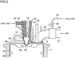
- FIG. 2 is a partial cross-sectional view of a combustion chamber and its peripheral structure. Described as an example in the present embodiment is a gas engine equipped with a turbocharger for driving a generator, the gas engine including a precombustion chamber for ignition.
- the present invention is not limited to the gas engine of the present embodiment, and can be applied to a gas engine of a combustion method according to the second embodiment described below. Further, while an object that is to be driven is preferably a generator 1, the present invention can be applied to a case where the object is not a generator.
- an engine (gas engine) 2 includes a cylinder block 4, cylinder heads 6, a flywheel 8, and a turbocharger 10 including an exhaust turbine 10a and a compressor 10b. Further, a generator 1 is directly mounted to the flywheel 8.
- a supply-air branch pipe 12 is connected to an air-supply inlet of each of the cylinder heads 6.
- Each supply-air branch pipe 12 is connected a supply-air outlet of the compressor 10b via a supply-air pipe 14.
- a supply-air cooler 16 for cooling supply air flowing through the supply-air pipe 14 is disposed in the supply-air pipe 14.
- an exhaust pipe 18 is connected to an exhaust outlet of each cylinder head 6.
- Each exhaust pipe 18 is connected to an exhaust inlet of the exhaust turbine 10a via an exhaust collecting pipe 20.
- An exhaust outlet pipe 22 for discharging exhaust gas is connected to an exhaust-gas outlet of the exhaust turbine 10a.
- a waste gate pipe 24 is branched from the exhaust collecting pipe 20 at the inlet side of the exhaust turbine 10a to bypass the exhaust turbine 10a, and connected to the exhaust outlet pipe 22 at the outlet side of the exhaust turbine 10a.
- a waste gate valve 26 is disposed in the waste gate pipe 24. The waste gate valve 26 varies a channel area of the waste gate pipe 24 to adjust a turbocharging pressure of the compressor 10b.
- a turbocharger-inlet air channel 28 for introducing air from the outside is connected to the compressor 10b of the turbocharger 10.
- Fuel gas is introduced into a gas supply pipe 30 from a fuel gas tank (not illustrated) storing the fuel gas.
- the gas supply pipe 30 is connected to a gas supply main pipe 32, and the gas supply main pipe 32 is branched at the middle into gas supply branch pipes 34 for the respective cylinders to be connected to the respective supply-air branch pipes 12. Further, the fuel gas is compressed and fed to the gas supply main pipe 12 by a gas compressor 31.
- Each gas supply branch pipe 34 includes a fuel flow-rate control valve 36 for controlling a channel area of the corresponding gas supply branch pipe 34, which is the flow rate of the fuel gas.
- a precombustion-chamber fuel gas supply pipe 44 is connected to each cylinder head 6. Each precombustion-chamber fuel gas supply pipe 44 supplies fuel gas to an ignition device 40 including a precombustion chamber 38 via a check valve 42.
- An engine speed sensor 46 for detecting an engine speed and a load sensor 48 for detecting the load of the generator 1, which is an engine load, are provided. Further, a thermometer 50 for measuring the ambient-air temperature and a humidity sensor 52 for measuring the relative humidity of the ambient air are disposed.
- FIG. 2 is a partial explanatory cross-sectional view of a combustion chamber and its peripheral structure of the engine 2 illustrated in FIG. 1 .
- a piston 56 that is reciprocably fitted in a cylinder 54, a main combustion chamber 58 defined and formed between an upper surface of the piston 56 and an inner surface of the cylinder block 4, an intake port 60 connected to the main combustion chamber 58, and an intake valve 62 for opening and closing the intake port 60, are provided.
- a gas mixer 64 is disposed in the air-supply branch pipe 12 at the upstream side of the intake port 60 and the gas supply branch pipe 34 is connected to the gas mixer 64, so that fuel gas supplied through the gas supply branch pipe 34 and air supplied through the supply-air branch pipe 12 are pre-mixed in the gas mixer 64.
- the gas supply branch pipe 34 may be connected to the intake-air branch pipe 12 directly and the gas and the air may be mixed without involving the gas mixer 64.
- the mixed gas passes through the intake port 60 to arrive at the intake valve 62, and is supplied to the main combustion chamber 58 as the intake valve 62 opens.
- a precombustion chamber 38 is formed inside a precombustion-chamber cap 66.
- a plurality of nozzles 68 is formed around a tip portion of the precombustion-chamber cap 66. The nozzles 68 inject flames into the main combustion chamber 58 to perform main combustion.
- the precombustion-chamber cap 66 is mounted to a tip portion of a nozzle holder 67.
- a precombustion-chamber fuel gas channel 70 and a spark plug 72 are disposed inside the nozzle holder 67.
- the spark plug 72 ignites fuel gas supplied from the combustion-chamber fuel gas channel 70 to the precombustion chamber 38.
- a precombustion-chamber fuel gas supply pipe 44 is connected to the precombustion-chamber fuel gas channel 70, and fuel gas is supplied to the precombustion chamber 38 via the check valve 42. Pressurized fuel gas is supplied from the upstream side of the check valve 42 in accordance with the ignition timing of the spark plug 72.
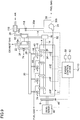
- the engine control device 74 includes an ignition-timing control unit 76, an air-fuel rate control unit 78, an switching unit to operation mode 84, a NOx reduction demand determination unit 86, and an output control unit 88.
- the ignition-timing control unit 76 mainly controls the ignition timing of the spark plug 72 to ignite fuel gas supplied into the precombustion chamber 38, thereby controlling the ignition timing of the mixed air in the main combustion chamber 58.
- the air-fuel rate control unit 78 controls the air-fuel rate in the main combustion chamber 58.
- the switching unit to operation mode 84 switches the operation mode between a basic operation mode 80 and a low NOx operation mode 82.
- the NOx reduction demand determination unit 86 determines whether it is necessary to restrict the amount of NOx emission temporarily on the basis of at least one of an environmental condition, a geographical condition or an engine operation elapse condition.
- the output control unit 88 controls the engine output, i.e., the output power of the generator 1.
- the basic operation mode 80 is operation in which the ignition-timing control unit 76 and the air-fuel rate control unit 78 are controlled on the basis of signals of the engine speed and the engine load detected by the engine speed sensor 46 and the load sensor 48, with target values which are a target air-fuel rate (the first target air-fuel rate) and a target ignition timing (the first target ignition timing) calculated using a table of a map of the target air-fuel rate (the first target air-fuel rate) and the target ignition timing (the first target ignition timing) which are optimum, i.e., at which the fuel consumption rate reaches the best, with respect to the predetermined engine speed and engine load.
- target values which are a target air-fuel rate (the first target air-fuel rate) and a target ignition timing (the first target ignition timing) calculated using a table of a map of the target air-fuel rate (the first target air-fuel rate) and the target ignition timing (the first target ignition timing) which are optimum, i.e., at which the fuel consumption rate reaches the best
- the low NOx operation mode 82 is operation in which the ignition-timing control unit and the air-fuel rate control unit are controlled with target values which are the second target ignition timing retarded from the first target ignition timing by a predetermined amount and the second target air-fuel rate increased from the first target air-fuel rate by a predetermined amount.
- the low NOx operation mode 82 includes an ignition-timing retard unit 90 which retards from the first target ignition timing with good fuel consumption rate to the second target ignition timing, and an air-amount increasing unit 92 which increases the amount of air from the first target air-fuel rate with good fuel consumption to the second target air-fuel rate.
- the ignition timing retard unit 90 controls the ignition timing of the spark plug 72 to retard.
- the air-amount increasing unit 92 increases the amount of turbocharge by reducing the opening degree of the waste gate valve 26 of the turbocharger 10.
- the NOx reduction demand determination unit 86 determines the necessity to restrict the amount of NOx emission temporarily such as an environmental condition, a geographical condition and an engine operation elapse condition.
- operation conditions e.g. the first target ignition timing and the first target air-fuel rate
- the optimum fuel consumption after taking basic measures for exhaust gas to satisfy the exhaust-gas regulation value.
- the gas engine is operated under conditions in which NOx is addressed by further sacrificing the fuel consumption in response to a change in the environment, an operation period, or special NOx exhaust-gas regulations, the fuel consumption may be further deteriorated, which is not economically efficient.
- the NOx reduction demand determination unit 86 determines whether the necessity to address an environmental change, an operation period, or special NOx exhaust-gas regulations has arisen.
- the conditions determined by the NOx reduction demand determination unit 86 are as follows below. In accordance with the invention, at least the second condition is included. Combinations not including the second condition, represent examples departing from the invention as claimed.
- the NOx reduction demand determination unit 86 determines that NOx reduction is necessary if a smog alert is issued in a region where the engine 2 is installed or in its periphery.
- a smog alert is frequently issued during summer in an urban area. Further, an amount of power generation is generally required at power generation facilities in summer. Thus, when photochemical smog occurs in summer, it is necessary to restrict the amount of NOx emission in operation of an engine while maintaining the amount of power generation of a generator at a constant rate. In this case, the low NOx operation mode 82 for NOx reduction is adopted even if deterioration of the fuel consumption is to be involved.
- the low NOx operation mode 82 is effective in appropriately operating the gas engine taking account of a relationship between the increased-output operation during summer and the NOx reduction operation in view of a decrease in fuel consumption.
- the NOx reduction demand determination unit 86 also determines that NOx reduction is necessary if the ambient temperature at which the engine 2 is installed is a predetermined value or more and the humidity is a predetermined value or less, which is a high-temperature and low-humidity state.
- the temperature is 30°C or more and the relative humidity is 40% or less.
- the NOx reduction demand determination unit 86 determines that NOx reduction is necessary when a predetermined time before the next maintenance time or a predetermined time after a start of the first operation has passed on the basis of operation time data of the gas engine.
- the engine 2 is a gas engine for power generation and undergoes maintenance regularly for replacement of parts, for instance, in response to deterioration due to aging. Immediately before the maintenance time, however, the engine would have been operated for a long period of time and the exhaust gas condition would tend to deteriorate.
- the NOx reduction demand determination unit 86 determines that NOx reduction is necessary when a moving body such as the vehicle, the ship, and the airplane approaches or enters a regulation area of the amount of NOx emission, e.g. when the moving body moves into a nation (territorial sea or air) having a different exhaust-gas regulation value or to a special region in the same nation where the regulation is strict.
- a detection result of the position information is compared to prestored data of the levels of the NOx regulation values of worldwide regions (including air and sea area), and the NOx reduction is determined to be necessary when entering such region.
- the NOx reduction level may be varied between the time of approach and the time of entry so that NOx reduction is executed in stages, executing the first-stage NOx reduction at the time of approach within a predetermined distance and executing further NOx reduction at the stage of entry into the region.
- the above determination conditions of the NOx reduction demand determination unit 86 may be suitably combined to determine the reduction demand even more precisely. For instance, it is determined that NOx reduction is even more necessary by combining the first condition of issuance of a photochemical smog alert and the second condition of the high-temperature and low-humidity state of the ambient-air condition.
- a combination of the second condition of the high-temperature and the low-humidity state of the ambient-air condition and the third condition of the time immediately before the maintenance time, and a combination of the third condition of the time immediately before the maintenance time and the fourth condition of approach or entry to the regulation region of the amount of NOx emission are especially effective.
- the switching unit to operation mode 84 of the engine control device 74 switches the operation mode from the basic operation mode 80 to the low NOx operation mode 82.
- the switching unit to operation mode 84 maintains the operation mode if the operation mode is the basic operation mode 80, and switches the operation to return to the basic operation mode 80 if the operation mode is the low NOx operation mode 82.
- the output control unit 88 maintains the output power of the generator 1 at a constant rate by maintaining the engine output, i.e., the engine speed at a constant rate.
- the ignition timing is retarded and the amount of air is increased, but the retard angle of the ignition timing, the amount of air increase, and the amount of fuel gas are controlled so that the engine output does not change considerably.
- step S1 After the operation is started, it is determined whether the NOx reduction condition is met in step S1. The determination is performed by the NOx reduction demand determination unit 86 on the basis of whether a NOx total amount regulation issuance signal (photochemical smog issuance signal) 91 is issued, or on the basis of an ambient-air condition signal (a signal determining a predetermined high-temperature and low-humidity state from detection signals from the thermometer 50 and the humidity sensor 52) 93.
- a NOx total amount regulation issuance signal photochemical smog issuance signal
- an ambient-air condition signal a signal determining a predetermined high-temperature and low-humidity state from detection signals from the thermometer 50 and the humidity sensor 52
- time-series change signal (a signal indicating having a predetermined time before the maintenance time from information of a maintenance-time signal, or passage of a predetermined time after the start of operation) 94.
- determination is performed by determining approach or entry to a regulation region of the amount of NOx emission on the basis of a NOx emission amount regulation region signal (position information signal) 96.
- step S1 The determination in step S1 is repeated until the NOx reduction condition is met. If the NOx reduction is met, the process advances to step S2 and the low NOx operation mode is turned ON by the switching unit to operation mode 84. Then, the process advances to step S3 and the low NOx operation mode is executed.
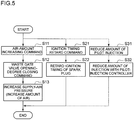
- the low NOx operation mode is executed according to the flow of the subroutine illustrated in FIG. 5 .
- step S4 the transition to the low NOx operation mode is completed by executing the flow illustrated in FIG. 5 .
- step S5 it is determined whether the NOx reduction condition is met, similarly to step S1. If the determination result is Yes, the process advances to step S6 and the low NOx operation mode 82 is continued and repeated until the NOx reduction condition becomes non-satisfied. Then, when the NOx reduction condition is not satisfied, the process advances to step S7 and the low NOx operation mode 82 is turned OFF. Subsequently, in step S8, the low NOx operation mode is canceled. In the cancellation of the low NOx operation mode, the subroutine illustrated in FIG. 5 is executed in a reversed order, changing the air-amount command value to a reduced side and the ignition timing to an advanced side.
- step S9 the flow illustrated in FIG. 5 is executed in a reversed order to complete halt of the low NOx operation mode, returning the operation mode to the basic operation mode 80.
- the air-amount increasing unit 92 is commanded to increase the amount of air in step S11 at first, and then the opening degree of the waste gate valve 26 is operated toward a closing direction to increase the supply-air pressure (to increase the amount of supply-air) in step S12. Simultaneously, in step S21, a retard command is sent to the ignition timing retard unit 90 to retard to the ignition timing of the spark plug 72 in step S22.
- Illustrated in FIG. 6 is a time chart in the low NOx operation mode 82 of the above engine control device 74.
- the time chart shows NOx concentration in the exhaust gas, an engine output (generator output), retard of the ignition timing, and an increase in the amount of air from ON to OFF of the low NOx operation mode 82.
- the ignition timing is retarded at a rate of 2 deg / 5 minutes, and the amount of air is increased at a rate of 1%/ 5 minutes.
- the engine output is controlled to be maintained at a substantially constant rate.
- the switch is performed by returning the amount of air and the ignition timing at the same rate from the time of OFF.
- the switching unit to operation mode 84 switches the operation mode from the basic operation mode 80 to the low NOx operation mode 82, so that the air-fuel rate control unit 78 performs control on the basis of the second target air-fuel rate increased from the first target excess rate, and the ignition-timing control unit 76 performs control based on the second target ignition timing retarded from the first target ignition timing.
- the second embodiment is different from the first embodiment only in the combustion method.
- the second embodiment has a micro-pilot type precombustion-chamber structure instead of the ignition-plug type precombustion-chamber structure of the first embodiment.
- the other configuration is similar to that of the first embodiment, and the same feature is indicated by the same reference numeral and not described in detail.
- the ignition device 100 includes the precombustion chamber 38 formed inside the precombustion-chamber cap 66 mounted to a tip end portion of a nozzle holder 102.
- a fuel-injection valve 104 is disposed inside the nozzle holder 102. Liquid fuel (light oil) is supplied to the fuel injection valve 104 from an inlet pipe 106 of the liquid fuel.
- the premix mixed gas introduced into the main combustion chamber 58 via the intake valve 62 in the intake stroke is introduced into the precombustion chamber 38 through the nozzles 68 formed on the tip end portion of the precombustion-chamber cap 66 from the main combustion chamber 58 in the compression stroke.
- the liquid fuel is pilot-injected into the mixed gas from the fuel injection valve 104 to be combusted, and ignition flame generated by the combustion passes through the nozzles 68 to be circulated and injected into the main combustion chamber 58, so that the premix mixed gas in the main combustion chamber 58 is combusted.
- the engine control device 110 includes reduction of the amount of pilot injection in addition to the first embodiment.
- a pilot-injection amount reduction unit 112 reduces the amount of fuel for pilot injection, so as to weaken the flame strength of the ignition flame and reduce the combustion temperature in the main combustion chamber 58, thereby reducing the amount of NOx generation.
- a command is issued to reduce the amount of pilot injection in step S31, and a pilot-injection controller (not illustrated) reduces the amount of injection in step S32.
- retard of the ignition timing of the spark plug in steps S21, S22 in FIG. 5 is read as retard of the injection timing of the pilot injection.
- micro-pilot type precombustion-chamber structure of the second embodiment similarly to the first embodiment, it is possible to obtain an exhaust-gas control device whereby it is not necessary to continuously increase the target air-fuel rate and retard the ignition timing as well to perform NOx reduction operation, and stable operation is performed in the basic operation mode 80 focusing on fuel consumption when it is not necessary to perform NOx reduction operation, so that NOx is reduced and fuel consumption is improved.
- combustion-chamber structure having a precombustion-chamber structure is described in the second embodiment, a direct-injection type structure may be employed in which the pilot fuel (liquid fuel) is directly injected into the main combustion chamber.
- the fuel gas is introduced from the fuel gas tank (not illustrated) into the gas supply pipe 30, and the gas supply pipe 30 is connected to the gas supply main pipe 32, which is branched for the respective cylinders into the gas supply branch pipes 34 to be connected to the respective supply-air branch pipes 12.
- the fuel gas may not be necessarily supplied to each supply-air branch pipe 12 to produce premix mixed gas.
- a gas mixer 116 may be disposed on the upstream side of the compressor 10b of the turbocharger 10 to produce premix mixed gas by supplying fuel gas via a gas adjustment valve 118, or further, the gas may be mixed both in the supply-air branch pipes 12 and at the upstream side of the turbocharger 10 as illustrated in FIG. 9 .
- the gas supply pipe 30 for introducing fuel gas from a fuel gas tank is branched into a turbocharger-side gas supply pipe 30a and a cylinder-side gas supply pipe 30b, and the turbocharger-side gas supply pipe 30a is connected to the gas mixer 116.
- the amount of fuel gas adjusted by the gas adjustment valve 118 is premixed with the air.
- a venturi mixer is preferably used as the gas mixer 116.
- the present invention it is possible to reduce NOx and improve fuel consumption by performing NOx restriction operation when environmental conditions or geographical conditions which require temporary restriction of the amount of NOx emission are satisfied, and otherwise performing stable operation focusing on the fuel consumption.
- the present invention can be suitably applied to a gas engine for power generation or a gas engine mounted to a moving body.
Landscapes
- Engineering & Computer Science (AREA)
- Chemical & Material Sciences (AREA)
- Mechanical Engineering (AREA)
- General Engineering & Computer Science (AREA)
- Combustion & Propulsion (AREA)
- Chemical Kinetics & Catalysis (AREA)
- Oil, Petroleum & Natural Gas (AREA)
- General Chemical & Material Sciences (AREA)
- Theoretical Computer Science (AREA)
- Signal Processing (AREA)
- Toxicology (AREA)
- Health & Medical Sciences (AREA)
- Combined Controls Of Internal Combustion Engines (AREA)
- Electrical Control Of Air Or Fuel Supplied To Internal-Combustion Engine (AREA)
- Output Control And Ontrol Of Special Type Engine (AREA)
Description
- The present invention relates to an exhaust-gas purification device for a gas engine. It especially relates to an exhaust-gas control device which is effective in restricting emission of NOx (nitrogen oxide) of a gas engine for a stationary generator or a ship.
- It is known that there is a trade-off relationship between the amount of NOx emission from an engine and the fuel consumption rate. It is desirable to operate the engine so as to reduce the fuel consumption rate while satisfying a NOx regulation value.
- To restrict production of NOx, it is effective to control the ignition timing and the air-fuel ratio. For instance,
Patent Document 1 discloses restricting knocking and production of NOx upon a change in fuel composition for a gas engine supplied with fuel with variable composition by controlling the ignition timing and the fuel-air ratio of the gas engine in accordance with the output of a fuel-composition measurement unit, a load measurement unit, and an engine speed measurement unit -
Patent Document 2 discloses closed loop NOx control responding to legislation requirements, based on continuous NOx emission measurements. Reduced NOx emission is achieved by increasing the lambda by reducing waste-gate exhaust gas amount and after that, if still not reaching NOx level, retarding the ignition angle. -
- Patent Document 1:
JP2003-148187A - Patent Document 2:
WO 2010/070199 A1 - The prior art at hand does not cover restriction of the amount of NOx emission based on the environmental state in which restriction of the amount of NOx emission is required.
- Specifically, the environmental condition in which the amount of NOx emission is required to be restricted temporarily is a case where the ambient environmental condition is such that the temperature is high and the humidity is low, which increases the combustion temperature.
- If a facility or a control of for addressing such temporary need for NOx restriction is always provided or operated at a high level, it may lead to deterioration in the fuel consumption rate of the engine or an increase in the installation cost.
- In this regard, if NOx-restriction operation is performed temporarily, it is possible to prevent deterioration in the fuel consumption and an increase in the installation cost as compared to a case where NOx-restriction operation is performed constantly, which is economically efficient.
- In a gas engine for a generator in particular, in order to restrict NOx, it is necessary to provide an expensive denitration facility and to operate the gas engine while restricting the power generation output. Thus, temporary restriction operation is effective in maintaining the power generation output at a constant rate and in restricting deterioration in the fuel consumption of the gas engine.
- In view of the above technical issues, an object of the present invention is to provide an exhaust-gas control device for a gas engine whereby NOx is reduced and fuel consumption is improved by performing NOx-restriction operation when environmental conditions in which temporary restriction of the amount of NOx emission is required are satisfied, and otherwise performing stable operation focusing on the fuel consumption.
- To achieve the above object, the present invention provides an exhaust-gas control device for a gas engine according to appended
claim 1. - According to the present invention, only when it is required to restrict the amount of NOx emission temporarily due to the environmental condition, the switching unit to operation mode switches the operation mode to the low NOx operation mode, so that the air-fuel rate control unit performs control based on the second target air-fuel rate increased from the first target excess rate, and the ignition-timing control unit performs control based on the second target ignition timing retarded from the first target ignition timing.
- Accordingly, it is possible to obtain an exhaust gas control device for a gas engine whereby it is not necessary to increase the target air-fuel rate and retard the ignition continuously to perform NOx reduction operation, and stable operation is performed focusing on the fuel consumption when not needed, which makes it possible to reduce NOx and improve fuel consumption.
- According to the present invention, the NOx reduction demand determination unit determines that there is a necessity when a high-temperature and low-humidity condition that an ambient temperature in which the gas engine is installed is a predetermined value or more and a humidity is a predetermined value or less is satisfied.
- With the above configuration, in a high-temperature and low-humidity state in which the ambient temperature is a predetermined value or more and the humidity is a predetermined value or less, the temperature of the supply air increases, and thus NOx is likely to be produced. Thus, it is possible to obtain the effect to reduce NOx efficiently by switching to the low NOx operation mode and performing the NOx reduction operation temporarily.
- As a condition of a high temperature and a low humidity, for instance, the temperature is 30°C or more and the relative humidity is 40% or less.
- Further, preferably in the present invention, the gas engine includes a turbocharger, and the low NOx operation mode unit may control the turbocharger so as to increase the air-fuel rate.
- With the above configuration, the waste gate flow amount of a turbocharger is controlled to increase the amount of turbocharge, which makes it possible to increase the excess air ratio. In this way, it is possible to enable NOx reduction operation.
- Accordingly, in a gas engine with a turbocharger, it is possible to obtain the effect to reduce NOx efficiently by switching to the low NOx operation mode and performing the NOx reduction operation temporarily.
- Further, preferably in the present invention, the gas engine may have a pilot-injection type combustion-chamber structure, and the air-fuel rate may be increased in the low NOx operation mode by reducing pilot fuel which is injected into a precombustion chamber or a main chamber.
- With the above configuration, it is possible to increase the air-fuel ratio by reducing the pilot fuel. In this way, it is possible to enable NOx reduction operation.
- As a result, in a case where the gas engine has a combustion-chamber structure of a pilot injection type, it is possible to obtain the effect to reduce NOx efficiently by switching to the low NOx operation mode and performing the NOx reduction operation temporarily.
- According to the present invention, it is possible to reduce NOx and improve fuel consumption by continuing and canceling the NOx restriction operation to switch the operation mode between NOx restriction operation and stable operation focusing on the fuel consumption, on the basis of occurrence condition of environmental conditions in which it is necessary to restrict the amount of NOx emission temporarily.
-
-
FIG. 1 is a system diagram of an overall configuration of a gas engine including an exhaust-gas control device according to the first embodiment of the present invention. -
FIG. 2 is a partial explanatory cross-sectional view of a peripheral structure of a combustion chamber of the first embodiment. -
FIG. 3 is a configuration block diagram of an engine control device. -
FIG. 4 is a control flow chart of an engine control device. -
FIG. 5 is a flowchart of a subroutine of low-NOx mode operation. -
FIG. 6 is a time chart of the NOx concentration, the engine output, the ignition timing, and the amount of air during the low-NOx mode operation. -
FIG. 7 is a partial explanatory cross-sectional view of a combustion chamber and its peripheral structure according to the second embodiment of the present invention. -
FIG. 8 is a configuration block diagram of an engine control device of the second embodiment. -
FIG. 9 is a variant of the first and second embodiments. - Embodiments of the present invention will now be described in detail with reference to the accompanying drawings.
-
FIG. 1 is an overall configuration diagram of a gas engine system according to the first embodiment of the present invention.FIG. 2 is a partial cross-sectional view of a combustion chamber and its peripheral structure. Described as an example in the present embodiment is a gas engine equipped with a turbocharger for driving a generator, the gas engine including a precombustion chamber for ignition. - The present invention is not limited to the gas engine of the present embodiment, and can be applied to a gas engine of a combustion method according to the second embodiment described below. Further, while an object that is to be driven is preferably a
generator 1, the present invention can be applied to a case where the object is not a generator. - In
FIG. 1 , an engine (gas engine) 2 includes acylinder block 4,cylinder heads 6, aflywheel 8, and aturbocharger 10 including anexhaust turbine 10a and acompressor 10b. Further, agenerator 1 is directly mounted to theflywheel 8. - A supply-
air branch pipe 12 is connected to an air-supply inlet of each of thecylinder heads 6. Each supply-air branch pipe 12 is connected a supply-air outlet of thecompressor 10b via a supply-air pipe 14. A supply-air cooler 16 for cooling supply air flowing through the supply-air pipe 14 is disposed in the supply-air pipe 14. - On the other hand, an
exhaust pipe 18 is connected to an exhaust outlet of eachcylinder head 6. Eachexhaust pipe 18 is connected to an exhaust inlet of theexhaust turbine 10a via anexhaust collecting pipe 20. Anexhaust outlet pipe 22 for discharging exhaust gas is connected to an exhaust-gas outlet of theexhaust turbine 10a. - Further, a
waste gate pipe 24 is branched from theexhaust collecting pipe 20 at the inlet side of theexhaust turbine 10a to bypass theexhaust turbine 10a, and connected to theexhaust outlet pipe 22 at the outlet side of theexhaust turbine 10a. Awaste gate valve 26 is disposed in thewaste gate pipe 24. Thewaste gate valve 26 varies a channel area of thewaste gate pipe 24 to adjust a turbocharging pressure of thecompressor 10b. - A turbocharger-
inlet air channel 28 for introducing air from the outside is connected to thecompressor 10b of theturbocharger 10. Fuel gas is introduced into agas supply pipe 30 from a fuel gas tank (not illustrated) storing the fuel gas. Thegas supply pipe 30 is connected to a gas supplymain pipe 32, and the gas supplymain pipe 32 is branched at the middle into gassupply branch pipes 34 for the respective cylinders to be connected to the respective supply-air branch pipes 12. Further, the fuel gas is compressed and fed to the gas supplymain pipe 12 by agas compressor 31. - Each gas
supply branch pipe 34 includes a fuel flow-rate control valve 36 for controlling a channel area of the corresponding gassupply branch pipe 34, which is the flow rate of the fuel gas. - Further, a precombustion-chamber fuel
gas supply pipe 44 is connected to eachcylinder head 6. Each precombustion-chamber fuelgas supply pipe 44 supplies fuel gas to anignition device 40 including aprecombustion chamber 38 via acheck valve 42. - An
engine speed sensor 46 for detecting an engine speed and aload sensor 48 for detecting the load of thegenerator 1, which is an engine load, are provided. Further, athermometer 50 for measuring the ambient-air temperature and ahumidity sensor 52 for measuring the relative humidity of the ambient air are disposed. -
FIG. 2 is a partial explanatory cross-sectional view of a combustion chamber and its peripheral structure of theengine 2 illustrated inFIG. 1 . Apiston 56 that is reciprocably fitted in acylinder 54, amain combustion chamber 58 defined and formed between an upper surface of thepiston 56 and an inner surface of thecylinder block 4, anintake port 60 connected to themain combustion chamber 58, and anintake valve 62 for opening and closing theintake port 60, are provided. - A
gas mixer 64 is disposed in the air-supply branch pipe 12 at the upstream side of theintake port 60 and the gassupply branch pipe 34 is connected to thegas mixer 64, so that fuel gas supplied through the gassupply branch pipe 34 and air supplied through the supply-air branch pipe 12 are pre-mixed in thegas mixer 64. The gassupply branch pipe 34 may be connected to the intake-air branch pipe 12 directly and the gas and the air may be mixed without involving thegas mixer 64. - Then, the mixed gas passes through the
intake port 60 to arrive at theintake valve 62, and is supplied to themain combustion chamber 58 as theintake valve 62 opens. - Further, a
precombustion chamber 38 is formed inside a precombustion-chamber cap 66. A plurality ofnozzles 68 is formed around a tip portion of the precombustion-chamber cap 66. Thenozzles 68 inject flames into themain combustion chamber 58 to perform main combustion. - The precombustion-
chamber cap 66 is mounted to a tip portion of anozzle holder 67. A precombustion-chamberfuel gas channel 70 and aspark plug 72 are disposed inside thenozzle holder 67. Thespark plug 72 ignites fuel gas supplied from the combustion-chamberfuel gas channel 70 to theprecombustion chamber 38. A precombustion-chamber fuelgas supply pipe 44 is connected to the precombustion-chamberfuel gas channel 70, and fuel gas is supplied to theprecombustion chamber 38 via thecheck valve 42. Pressurized fuel gas is supplied from the upstream side of thecheck valve 42 in accordance with the ignition timing of thespark plug 72. - Next, an
engine control device 74 for a gas engine with the above configuration will be described. - As illustrated in
FIG. 3 , theengine control device 74 includes an ignition-timing control unit 76, an air-fuelrate control unit 78, an switching unit tooperation mode 84, a NOx reductiondemand determination unit 86, and anoutput control unit 88. The ignition-timing control unit 76 mainly controls the ignition timing of thespark plug 72 to ignite fuel gas supplied into theprecombustion chamber 38, thereby controlling the ignition timing of the mixed air in themain combustion chamber 58. The air-fuelrate control unit 78 controls the air-fuel rate in themain combustion chamber 58. The switching unit tooperation mode 84 switches the operation mode between abasic operation mode 80 and a lowNOx operation mode 82. The NOx reductiondemand determination unit 86 determines whether it is necessary to restrict the amount of NOx emission temporarily on the basis of at least one of an environmental condition, a geographical condition or an engine operation elapse condition. Theoutput control unit 88 controls the engine output, i.e., the output power of thegenerator 1. - The
basic operation mode 80 is operation in which the ignition-timing control unit 76 and the air-fuelrate control unit 78 are controlled on the basis of signals of the engine speed and the engine load detected by theengine speed sensor 46 and theload sensor 48, with target values which are a target air-fuel rate (the first target air-fuel rate) and a target ignition timing (the first target ignition timing) calculated using a table of a map of the target air-fuel rate (the first target air-fuel rate) and the target ignition timing (the first target ignition timing) which are optimum, i.e., at which the fuel consumption rate reaches the best, with respect to the predetermined engine speed and engine load. - On the other hand, the low
NOx operation mode 82 is operation in which the ignition-timing control unit and the air-fuel rate control unit are controlled with target values which are the second target ignition timing retarded from the first target ignition timing by a predetermined amount and the second target air-fuel rate increased from the first target air-fuel rate by a predetermined amount. - Specifically, the low
NOx operation mode 82 includes an ignition-timing retard unit 90 which retards from the first target ignition timing with good fuel consumption rate to the second target ignition timing, and an air-amount increasing unit 92 which increases the amount of air from the first target air-fuel rate with good fuel consumption to the second target air-fuel rate. The ignitiontiming retard unit 90 controls the ignition timing of thespark plug 72 to retard. Further, the air-amount increasing unit 92 increases the amount of turbocharge by reducing the opening degree of thewaste gate valve 26 of theturbocharger 10. - Further, the NOx reduction
demand determination unit 86 determines the necessity to restrict the amount of NOx emission temporarily such as an environmental condition, a geographical condition and an engine operation elapse condition. - For the
engine 2, operation conditions (e.g. the first target ignition timing and the first target air-fuel rate) are set at the optimum fuel consumption after taking basic measures for exhaust gas to satisfy the exhaust-gas regulation value. - However, if the gas engine is operated under conditions in which NOx is addressed by further sacrificing the fuel consumption in response to a change in the environment, an operation period, or special NOx exhaust-gas regulations, the fuel consumption may be further deteriorated, which is not economically efficient.
- Thus, the NOx reduction
demand determination unit 86 determines whether the necessity to address an environmental change, an operation period, or special NOx exhaust-gas regulations has arisen. - The conditions determined by the NOx reduction
demand determination unit 86 are as follows below. In accordance with the invention, at least the second condition is included. Combinations not including the second condition, represent examples departing from the invention as claimed. - For instance, as a determination condition (the first condition), the NOx reduction
demand determination unit 86 determines that NOx reduction is necessary if a smog alert is issued in a region where theengine 2 is installed or in its periphery. - A smog alert is frequently issued during summer in an urban area. Further, an amount of power generation is generally required at power generation facilities in summer. Thus, when photochemical smog occurs in summer, it is necessary to restrict the amount of NOx emission in operation of an engine while maintaining the amount of power generation of a generator at a constant rate. In this case, the low
NOx operation mode 82 for NOx reduction is adopted even if deterioration of the fuel consumption is to be involved. - For a gas engine for power generation installed in suburbs of an urban area in particular, the low
NOx operation mode 82 is effective in appropriately operating the gas engine taking account of a relationship between the increased-output operation during summer and the NOx reduction operation in view of a decrease in fuel consumption. - When volatile organic compound contained in paint or adhesive agent as a medium and NOx (nitrogen oxide) contained in exhaust gas emitted from a vehicle or a factory receive ultraviolet from the sun to cause chemical reaction, a new substance called photochemical oxidant is produced. On a day when the temperature is high, wind is weak, and the sunlight is strong, the concentration of the photochemical oxidant in the atmospheric air increases and so-called photochemical smog is produced.
- Thus, if a photochemical smog alert is issued, it is possible to achieve the effect to reduce NOx efficiently by temporarily switching to the low NOx operation mode and performing the NOx reduction operation to reduce the amount of NOx emission, which is the cause of production of the photochemical smog.
- According to the claimed invention, as a determination condition (the second condition), the NOx reduction
demand determination unit 86 also determines that NOx reduction is necessary if the ambient temperature at which theengine 2 is installed is a predetermined value or more and the humidity is a predetermined value or less, which is a high-temperature and low-humidity state. - In a high-temperature and low-humidity state in which the ambient temperature is a predetermined value or more and the humidity is a predetermined value or less, the temperature of the supply air increases and the combustion temperature in the
main combustion chamber 58 also tends to increase, and thus NOx is likely to be produced. Thus, it is possible to obtain the effect to reduce NOx efficiently by switching to the low NOx operation mode and performing the NOx reduction operation temporarily. - Here, as a condition of a high temperature and a low humidity, for instance, the temperature is 30°C or more and the relative humidity is 40% or less.
- Further, as a determination condition (the third condition), the NOx reduction
demand determination unit 86 determines that NOx reduction is necessary when a predetermined time before the next maintenance time or a predetermined time after a start of the first operation has passed on the basis of operation time data of the gas engine. - The
engine 2 is a gas engine for power generation and undergoes maintenance regularly for replacement of parts, for instance, in response to deterioration due to aging. Immediately before the maintenance time, however, the engine would have been operated for a long period of time and the exhaust gas condition would tend to deteriorate. - At such a time, it is possible to obtain the effect to reduce NOx efficiently by switching the operation mode to the low NOx operation mode and performing the NOx reduction operation temporarily. Further, independently from the regular maintenance time, the exhaust gas condition tends to deteriorate when a predetermined time has passed after the start of the first operation. Thus, at such a time, switching to the low NOx operation mode and performing NOx reduction operation is efficient in terms of NOx reduction.
- Further, as a determination condition (the fourth condition), in a case where the
engine 2 is used as a main engine of a vehicle, a ship, or an air plane, or a case where theengine 2 is used as a power source for a generator mounted to the vehicle, the ship, or the airplane, the NOx reductiondemand determination unit 86 determines that NOx reduction is necessary when a moving body such as the vehicle, the ship, and the airplane approaches or enters a regulation area of the amount of NOx emission, e.g. when the moving body moves into a nation (territorial sea or air) having a different exhaust-gas regulation value or to a special region in the same nation where the regulation is strict. - Specifically, a detection result of the position information is compared to prestored data of the levels of the NOx regulation values of worldwide regions (including air and sea area), and the NOx reduction is determined to be necessary when entering such region.
- Here, the NOx reduction level may be varied between the time of approach and the time of entry so that NOx reduction is executed in stages, executing the first-stage NOx reduction at the time of approach within a predetermined distance and executing further NOx reduction at the stage of entry into the region.
- In this way, it is possible to apply the present teaching to a moving body which moves to a region having a different NOx regulation value.
- Further, the above determination conditions of the NOx reduction
demand determination unit 86 may be suitably combined to determine the reduction demand even more precisely. For instance, it is determined that NOx reduction is even more necessary by combining the first condition of issuance of a photochemical smog alert and the second condition of the high-temperature and low-humidity state of the ambient-air condition. - Further, a combination of the second condition of the high-temperature and the low-humidity state of the ambient-air condition and the third condition of the time immediately before the maintenance time, and a combination of the third condition of the time immediately before the maintenance time and the fourth condition of approach or entry to the regulation region of the amount of NOx emission are especially effective.
- When it is determined that reduction is necessary by the NOx reduction
demand determination unit 86, the switching unit tooperation mode 84 of theengine control device 74 switches the operation mode from thebasic operation mode 80 to the lowNOx operation mode 82. When it is determined that reduction is not necessary, the switching unit tooperation mode 84 maintains the operation mode if the operation mode is thebasic operation mode 80, and switches the operation to return to thebasic operation mode 80 if the operation mode is the lowNOx operation mode 82. - Further, the
output control unit 88 maintains the output power of thegenerator 1 at a constant rate by maintaining the engine output, i.e., the engine speed at a constant rate. During operation of the lowNOx operation mode 82, the ignition timing is retarded and the amount of air is increased, but the retard angle of the ignition timing, the amount of air increase, and the amount of fuel gas are controlled so that the engine output does not change considerably. - Next, with reference to the flowchart of
FIG. 4 , the control flow of theengine control device 74 will be described. - After the operation is started, it is determined whether the NOx reduction condition is met in step S1. The determination is performed by the NOx reduction
demand determination unit 86 on the basis of whether a NOx total amount regulation issuance signal (photochemical smog issuance signal) 91 is issued, or on the basis of an ambient-air condition signal (a signal determining a predetermined high-temperature and low-humidity state from detection signals from thethermometer 50 and the humidity sensor 52) 93. - Further, determination is performed on the basis of a time-series change signal (a signal indicating having a predetermined time before the maintenance time from information of a maintenance-time signal, or passage of a predetermined time after the start of operation) 94.
- Still further, determination is performed by determining approach or entry to a regulation region of the amount of NOx emission on the basis of a NOx emission amount regulation region signal (position information signal) 96.
- The determination in step S1 is repeated until the NOx reduction condition is met. If the NOx reduction is met, the process advances to step S2 and the low NOx operation mode is turned ON by the switching unit to
operation mode 84. Then, the process advances to step S3 and the low NOx operation mode is executed. - The low NOx operation mode is executed according to the flow of the subroutine illustrated in
FIG. 5 . In step S4, the transition to the low NOx operation mode is completed by executing the flow illustrated inFIG. 5 . - Next, the process advances to step S5 and it is determined whether the NOx reduction condition is met, similarly to step S1. If the determination result is Yes, the process advances to step S6 and the low
NOx operation mode 82 is continued and repeated until the NOx reduction condition becomes non-satisfied. Then, when the NOx reduction condition is not satisfied, the process advances to step S7 and the lowNOx operation mode 82 is turned OFF. Subsequently, in step S8, the low NOx operation mode is canceled. In the cancellation of the low NOx operation mode, the subroutine illustrated inFIG. 5 is executed in a reversed order, changing the air-amount command value to a reduced side and the ignition timing to an advanced side. - Then, in step S9, the flow illustrated in
FIG. 5 is executed in a reversed order to complete halt of the low NOx operation mode, returning the operation mode to thebasic operation mode 80. - In the subroutine of the low NOx operation mode illustrated in
FIG. 5 , the air-amount increasing unit 92 is commanded to increase the amount of air in step S11 at first, and then the opening degree of thewaste gate valve 26 is operated toward a closing direction to increase the supply-air pressure (to increase the amount of supply-air) in step S12. Simultaneously, in step S21, a retard command is sent to the ignitiontiming retard unit 90 to retard to the ignition timing of thespark plug 72 in step S22. - Illustrated in
FIG. 6 is a time chart in the lowNOx operation mode 82 of the aboveengine control device 74. The time chart shows NOx concentration in the exhaust gas, an engine output (generator output), retard of the ignition timing, and an increase in the amount of air from ON to OFF of the lowNOx operation mode 82. - In a case of transition to the low
NOx operation mode 82, for instance, the ignition timing is retarded at a rate of 2 deg / 5 minutes, and the amount of air is increased at a rate of 1%/ 5 minutes. The engine output is controlled to be maintained at a substantially constant rate. Further, also in a case of return to thebasic operation mode 80, similarly to the transition to the lowNOx operation mode 82, the switch is performed by returning the amount of air and the ignition timing at the same rate from the time of OFF. - According to the above first embodiment, only when the need to restrict the amount of NOx emission temporarily arises due to a condition in respect of an ambient temperature in which the gas engine is installed and a humidity, the switching unit to
operation mode 84 switches the operation mode from thebasic operation mode 80 to the lowNOx operation mode 82, so that the air-fuelrate control unit 78 performs control on the basis of the second target air-fuel rate increased from the first target excess rate, and the ignition-timing control unit 76 performs control based on the second target ignition timing retarded from the first target ignition timing. - Accordingly, it is possible to obtain an exhaust gas control device for a gas engine whereby it is not necessary to increase the target air-fuel rate and retard the ignition timing continuously to perform NOx reduction operation, and stable operation focusing on the fuel consumption is performed by the
basic operation mode 80 when the NOx reduction operation is not needed, so that NOx is reduced and the fuel consumption is improved. - With reference to
FIGs. 5 ,7 , and8 , the second embodiment will be described. - The second embodiment is different from the first embodiment only in the combustion method. The second embodiment has a micro-pilot type precombustion-chamber structure instead of the ignition-plug type precombustion-chamber structure of the first embodiment. The other configuration is similar to that of the first embodiment, and the same feature is indicated by the same reference numeral and not described in detail.
- As illustrated in
FIG. 7 , theignition device 100 includes theprecombustion chamber 38 formed inside the precombustion-chamber cap 66 mounted to a tip end portion of anozzle holder 102. A fuel-injection valve 104 is disposed inside thenozzle holder 102. Liquid fuel (light oil) is supplied to thefuel injection valve 104 from aninlet pipe 106 of the liquid fuel. - Then, the premix mixed gas introduced into the
main combustion chamber 58 via theintake valve 62 in the intake stroke is introduced into theprecombustion chamber 38 through thenozzles 68 formed on the tip end portion of the precombustion-chamber cap 66 from themain combustion chamber 58 in the compression stroke. The liquid fuel is pilot-injected into the mixed gas from thefuel injection valve 104 to be combusted, and ignition flame generated by the combustion passes through thenozzles 68 to be circulated and injected into themain combustion chamber 58, so that the premix mixed gas in themain combustion chamber 58 is combusted. - As indicated by the dotted line in
FIG. 5 , theengine control device 110 according to the above second embodiment includes reduction of the amount of pilot injection in addition to the first embodiment. In the lowNOx operation mode 114, a pilot-injection amount reduction unit 112 reduces the amount of fuel for pilot injection, so as to weaken the flame strength of the ignition flame and reduce the combustion temperature in themain combustion chamber 58, thereby reducing the amount of NOx generation. As illustrated in the flowchart ofFIG. 5 , to execute the lowNOx operation mode 114, a command is issued to reduce the amount of pilot injection in step S31, and a pilot-injection controller (not illustrated) reduces the amount of injection in step S32.
Here, in the second embodiment, retard of the ignition timing of the spark plug in steps S21, S22 inFIG. 5 is read as retard of the injection timing of the pilot injection. - Also in the micro-pilot type precombustion-chamber structure of the second embodiment, similarly to the first embodiment, it is possible to obtain an exhaust-gas control device whereby it is not necessary to continuously increase the target air-fuel rate and retard the ignition timing as well to perform NOx reduction operation, and stable operation is performed in the
basic operation mode 80 focusing on fuel consumption when it is not necessary to perform NOx reduction operation, so that NOx is reduced and fuel consumption is improved. - Further, while a combustion-chamber structure having a precombustion-chamber structure is described in the second embodiment, a direct-injection type structure may be employed in which the pilot fuel (liquid fuel) is directly injected into the main combustion chamber.
- In the first and second embodiments, as illustrated in
FIG. 1 , the fuel gas is introduced from the fuel gas tank (not illustrated) into thegas supply pipe 30, and thegas supply pipe 30 is connected to the gas supplymain pipe 32, which is branched for the respective cylinders into the gassupply branch pipes 34 to be connected to the respective supply-air branch pipes 12. However, the fuel gas may not be necessarily supplied to each supply-air branch pipe 12 to produce premix mixed gas. Instead, agas mixer 116 may be disposed on the upstream side of thecompressor 10b of theturbocharger 10 to produce premix mixed gas by supplying fuel gas via agas adjustment valve 118, or further, the gas may be mixed both in the supply-air branch pipes 12 and at the upstream side of theturbocharger 10 as illustrated inFIG. 9 . - As illustrated in
FIG. 9 , thegas supply pipe 30 for introducing fuel gas from a fuel gas tank (not illustrated) is branched into a turbocharger-sidegas supply pipe 30a and a cylinder-sidegas supply pipe 30b, and the turbocharger-sidegas supply pipe 30a is connected to thegas mixer 116. The amount of fuel gas adjusted by thegas adjustment valve 118 is premixed with the air. Further, as thegas mixer 116, a venturi mixer is preferably used. - According to the present invention, it is possible to reduce NOx and improve fuel consumption by performing NOx restriction operation when environmental conditions or geographical conditions which require temporary restriction of the amount of NOx emission are satisfied, and otherwise performing stable operation focusing on the fuel consumption. Thus, the present invention can be suitably applied to a gas engine for power generation or a gas engine mounted to a moving body.
-
- 1
- Generator
- 2
- Engine (Gas engine)
- 4
- Cylinder block
- 6
- Cylinder head
- 8
- Flywheel
- 10
- Turbocharger
- 10a
- Exhaust turbine
- 10b
- Compressor
- 26
- Waste gate valve
- 38
- Precombustion chamber
- 46
- Engine speed sensor
- 48
- Load sensor
- 50
- Thermometer
- 52
- Humidity sensor
- 58
- Main combustion chamber (combustion chamber)
- 74, 110
- Engine control device (Exhaust-gas control device)
- 76
- Ignition-timing control unit
- 78
- Air-fuel rate control unit
- 80
- Basic operation mode
- 82
- Low NOx operation mode
- 84
- Switching unit to operation mode
- 86
- NOx reduction demand determination unit
- 88
- Output control unit
- 90
- Ignition timing retard unit
- 91
- NOx total amount regulation issuance signal
- 92
- Air amount increasing unit
- 93
- Ambient-air condition signal
- 94
- Time-series change signal
- 96
- NOx emission amount regulation region signal
- 112
- Pilot-injection amount reduction unit
Claims (3)
- An exhaust-gas control device (74) for a gas engine which mixes fuel gas and air and supplies mixed gas to a combustion chamber, comprising an ignition-timing control unit (76) configured to control an ignition timing of the mixed gas supplied into the combustion chamber, and an air-fuel rate control unit (78) configured to control an air-fuel rate in the combustion chamber,
characterized in that
the exhaust-gas control device comprises:a basic operation mode unit (80) configured to control the ignition-timing control unit and the air-fuel rate control unit, having a first target ignition timing and a first target air-fuel rate as target values which are set as an ignition timing and an air-fuel rate at which a fuel consumption rate is the best on the basis of an engine speed and an engine load;a NOx reduction demand determination unit (86) configured to determine that there is a necessity to restrict an amount of NOx emission temporarily if an ambient temperature in which the gas engine is installed is a predetermined value or more and a humidity is a predetermined value or less;a low NOx operation mode unit (90) configured to control the ignition-timing control unit and the air-fuel rate control unit, having a second target ignition timing retarded from the first target ignition timing and a second target air-fuel rate increased from the first target air-fuel rate as target values; anda switching unit (84) to operation mode configured to switch an operation mode to the low NOx operation mode when it is determined by the NOx reduction demand determination unit (86) that there is a necessity to restrict the amount of NOx emission, and configured to, when it is determined by the NOx reduction demand determination unit (86) that there is no necessity to restrict the amount of NOx emission, maintain the operation mode if the operation mode is the basic operation mode, and switch the operation to return to the basic operation if the operation mode is the low NOx operation mode. - The exhaust-gas control device for a gas engine according to claim 1,
wherein the gas engine (2) includes a turbocharger (10), and the low NOx operation mode unit controls the turbocharger so as to increase the air-fuel rate. - The exhaust-gas control device for a gas engine according to claim 1 or 2,
wherein the gas engine (2) has a pilot-injection type combustion-chamber structure, and the air-fuel rate is increased in the low NOx operation mode by reducing pilot fuel which is injected into a precombustion chamber or a main chamber.
Applications Claiming Priority (2)
| Application Number | Priority Date | Filing Date | Title |
|---|---|---|---|
| JP2013056775A JP5980151B2 (en) | 2013-03-19 | 2013-03-19 | Exhaust gas control device for gas engine |
| PCT/JP2014/054052 WO2014148192A1 (en) | 2013-03-19 | 2014-02-20 | Exhaust gas control device of gas engine |
Publications (3)
| Publication Number | Publication Date |
|---|---|
| EP2977595A1 EP2977595A1 (en) | 2016-01-27 |
| EP2977595A4 EP2977595A4 (en) | 2016-12-28 |
| EP2977595B1 true EP2977595B1 (en) | 2021-04-07 |
Family
ID=51579884
Family Applications (1)
| Application Number | Title | Priority Date | Filing Date |
|---|---|---|---|
| EP14767698.5A Active EP2977595B1 (en) | 2013-03-19 | 2014-02-20 | Exhaust gas control device for a gas engine |
Country Status (6)
| Country | Link |
|---|---|
| US (1) | US9551285B2 (en) |
| EP (1) | EP2977595B1 (en) |
| JP (1) | JP5980151B2 (en) |
| KR (1) | KR101789897B1 (en) |
| CN (1) | CN105008698B (en) |
| WO (1) | WO2014148192A1 (en) |
Families Citing this family (26)
| Publication number | Priority date | Publication date | Assignee | Title |
|---|---|---|---|---|
| US9172217B2 (en) | 2010-11-23 | 2015-10-27 | Woodward, Inc. | Pre-chamber spark plug with tubular electrode and method of manufacturing same |
| US8584648B2 (en) | 2010-11-23 | 2013-11-19 | Woodward, Inc. | Controlled spark ignited flame kernel flow |
| US9476347B2 (en) | 2010-11-23 | 2016-10-25 | Woodward, Inc. | Controlled spark ignited flame kernel flow in fuel-fed prechambers |
| US9856848B2 (en) | 2013-01-08 | 2018-01-02 | Woodward, Inc. | Quiescent chamber hot gas igniter |
| JP5980151B2 (en) | 2013-03-19 | 2016-08-31 | 三菱重工業株式会社 | Exhaust gas control device for gas engine |
| US9765682B2 (en) | 2013-06-10 | 2017-09-19 | Woodward, Inc. | Multi-chamber igniter |
| US20190301351A1 (en) | 2015-08-24 | 2019-10-03 | Akela Industries Inc. | Pre-combustion chamber apparatus and method for pre-combustion |
| JP6561362B2 (en) * | 2014-10-29 | 2019-08-21 | 株式会社三井E&Sマシナリー | Ship engine operation system |
| US9653886B2 (en) | 2015-03-20 | 2017-05-16 | Woodward, Inc. | Cap shielded ignition system |
| US9840963B2 (en) | 2015-03-20 | 2017-12-12 | Woodward, Inc. | Parallel prechamber ignition system |
| AT517111B1 (en) * | 2015-06-29 | 2016-11-15 | Ge Jenbacher Gmbh & Co Og | Internal combustion engine with a control device |
| KR101992045B1 (en) * | 2015-07-23 | 2019-06-21 | 얀마 가부시키가이샤 | Engine device |
| US9890689B2 (en) * | 2015-10-29 | 2018-02-13 | Woodward, Inc. | Gaseous fuel combustion |
| DE102015015343A1 (en) * | 2015-11-26 | 2017-06-01 | Man Diesel & Turbo Se | Method and control device for operating an engine |
| US10208651B2 (en) * | 2016-02-06 | 2019-02-19 | Prometheus Applied Technologies, Llc | Lean-burn pre-combustion chamber |
| JP6919854B2 (en) * | 2017-03-31 | 2021-08-18 | 国立研究開発法人 海上・港湾・航空技術研究所 | Engine exhaust control system and ships equipped with it |
| SE542081C2 (en) * | 2017-04-21 | 2020-02-18 | Scania Cv Ab | Gas Engine, Method for Operating a Gas Engine and Generator Set |
| US10626840B2 (en) * | 2017-06-29 | 2020-04-21 | Ford Global Technologies, Llc | Methods and systems for spark timing control |
| SE542084C2 (en) | 2017-07-14 | 2020-02-25 | Lean Marine Sweden Ab | Method for controlling the propulsion of a ship by determined cylinder top pressure |
| DE102017214092B4 (en) * | 2017-08-11 | 2019-07-04 | Continental Automotive Gmbh | Control method and internal combustion engine |
| KR102422138B1 (en) * | 2017-11-01 | 2022-07-18 | 현대자동차주식회사 | Hybrid vehicle and method of controlling engine operation for the same |
| AT16719U1 (en) * | 2018-12-21 | 2020-07-15 | Innio Jenbacher Gmbh & Co Og | Cylinder head for an internal combustion engine |
| US11415041B2 (en) | 2019-09-16 | 2022-08-16 | Woodward, Inc. | Flame triggered and controlled volumetric ignition |
| WO2021163863A1 (en) * | 2020-02-18 | 2021-08-26 | 潍柴动力股份有限公司 | Engine control method and device |
| US11739702B2 (en) * | 2021-02-23 | 2023-08-29 | Aramco Services Company | Reheated residual gas ignitor |
| CN114183263B (en) * | 2021-10-29 | 2024-03-05 | 东风商用车有限公司 | Engine control method with multiple control modes |
Family Cites Families (26)
| Publication number | Priority date | Publication date | Assignee | Title |
|---|---|---|---|---|
| JPH08121201A (en) | 1994-10-27 | 1996-05-14 | Tokyo Gas Co Ltd | Knocking control method and device for gas engine |
| JP3337931B2 (en) * | 1997-01-30 | 2002-10-28 | マツダ株式会社 | In-cylinder injection engine |
| JPH11351047A (en) * | 1998-06-11 | 1999-12-21 | Yanmar Diesel Engine Co Ltd | Control method for internal combustion engine |
| JP4026991B2 (en) | 1999-07-23 | 2007-12-26 | 三洋電機株式会社 | Gas heat pump type air conditioner |
| JP2001107809A (en) * | 1999-10-06 | 2001-04-17 | Goto Ikueikai | Gas fuel internal combustion engine |
| JP4201491B2 (en) * | 2001-04-13 | 2008-12-24 | 三洋電機株式会社 | ENGINE CONTROL DEVICE AND ENGINE-DRIVEN HEAT PUMP DEVICE USING THE SAME |
| JP2003148187A (en) | 2001-11-12 | 2003-05-21 | Tokyo Gas Co Ltd | Device and method for controlling internal combustion engine |
| JP3719409B2 (en) | 2001-11-15 | 2005-11-24 | 三菱電機株式会社 | Ventilation equipment |
| JP2003239748A (en) * | 2002-02-18 | 2003-08-27 | Yanmar Co Ltd | Compressed self-ignition type internal combustion engine |
| JP2005188369A (en) * | 2003-12-25 | 2005-07-14 | Yanmar Co Ltd | Air fuel ratio control device |
| JP2005226621A (en) | 2004-02-16 | 2005-08-25 | Mitsubishi Heavy Ind Ltd | Engine system including instrumentation engine and operation method thereof |
| US7168411B2 (en) | 2004-10-01 | 2007-01-30 | Southwest Research Institute | Closed loop engine control for regulating NOx emissions, using a two-dimensional fuel-air curve |
| DE112006000529B4 (en) * | 2005-03-03 | 2016-02-18 | General Motors Global Technology Operations, Inc. | A method of controlling transient loads between lean and stoichiometric combustion modes of direct injection self-ignition combustion engines |
| JP4482491B2 (en) * | 2005-06-17 | 2010-06-16 | 本田技研工業株式会社 | Control device for internal combustion engine |
| US7992377B2 (en) * | 2006-12-14 | 2011-08-09 | GM Global Technology Operations LLC | Diesel exhaust control during limp-home mode |
| JP4563443B2 (en) | 2007-12-14 | 2010-10-13 | 三菱重工業株式会社 | Gas engine system control method and system |
| JP4599390B2 (en) | 2007-12-14 | 2010-12-15 | 三菱重工業株式会社 | Micro pilot injection gas engine |
| JP4616878B2 (en) | 2007-12-14 | 2011-01-19 | 三菱重工業株式会社 | Gas engine system control method and system |
| JP2010007518A (en) * | 2008-06-25 | 2010-01-14 | Nissan Motor Co Ltd | Exhaust emission control device and exhaust emission control method for diesel engine |
| FI124007B (en) * | 2008-12-16 | 2014-01-31 | Waertsilae Finland Oy | Method and system for controlling combustion engine emissions |
| JP2011127544A (en) * | 2009-12-18 | 2011-06-30 | Yanmar Co Ltd | Gas engine control device |
| EP2405120B1 (en) | 2010-03-26 | 2019-07-10 | Toyota Jidosha Kabushiki Kaisha | Combustion controller for internal combustion engine |
| JPWO2011125976A1 (en) * | 2010-04-02 | 2013-07-11 | 株式会社マサインタナショナル | Heat engine and power generation system using the heat engine |
| JP5314637B2 (en) * | 2010-05-31 | 2013-10-16 | 三菱重工業株式会社 | Gas engine |
| JP2013024047A (en) * | 2011-07-15 | 2013-02-04 | Daihatsu Diesel Mfg Co Ltd | Fuel injection valve |
| JP5980151B2 (en) | 2013-03-19 | 2016-08-31 | 三菱重工業株式会社 | Exhaust gas control device for gas engine |
-
2013
- 2013-03-19 JP JP2013056775A patent/JP5980151B2/en active Active
-
2014
- 2014-02-20 WO PCT/JP2014/054052 patent/WO2014148192A1/en active Application Filing
- 2014-02-20 EP EP14767698.5A patent/EP2977595B1/en active Active
- 2014-02-20 CN CN201480011512.6A patent/CN105008698B/en active Active
- 2014-02-20 US US14/777,432 patent/US9551285B2/en active Active
- 2014-02-20 KR KR1020157025570A patent/KR101789897B1/en active IP Right Grant
Non-Patent Citations (1)
| Title |
|---|
| None * |
Also Published As
| Publication number | Publication date |
|---|---|
| JP2014181614A (en) | 2014-09-29 |
| CN105008698B (en) | 2019-01-01 |
| KR101789897B1 (en) | 2017-10-25 |
| JP5980151B2 (en) | 2016-08-31 |
| US9551285B2 (en) | 2017-01-24 |
| KR20150119394A (en) | 2015-10-23 |
| EP2977595A1 (en) | 2016-01-27 |
| CN105008698A (en) | 2015-10-28 |
| WO2014148192A1 (en) | 2014-09-25 |
| US20160047323A1 (en) | 2016-02-18 |
| EP2977595A4 (en) | 2016-12-28 |
Similar Documents
| Publication | Publication Date | Title |
|---|---|---|
| EP2977595B1 (en) | Exhaust gas control device for a gas engine | |
| EP2652293B1 (en) | Method of operating an internal combustion piston engine in transient load change, a control system for controlling the operating of an internal combustion engine, and a piston engine | |
| US11242784B2 (en) | Method and systems for engine control | |
| CN102884300A (en) | Control method of spark ignition engine and spark ignition engine | |
| US9964053B2 (en) | Combustion control device for gas engine | |
| US11092094B2 (en) | Methods and systems for engine control | |
| EA028553B8 (en) | System and method of operating an internal combustion engine | |
| CN109882270B (en) | Internal combustion engine nitrogen oxide emission closed-loop control system for in-cylinder ionic current and urea injection | |
| CN101627198A (en) | Method and apparatus for controlling fuel injection in a homogeneous charge compression ignition engine | |
| Wang et al. | Numerical and thermodynamic study on effects of high and low pressure exhaust gas recirculation on turbocharged marine low-speed engine | |
| KR20090096315A (en) | A method for the operation of a longitudinally scavenged two-stroke large diesel engine and a longitudinally scavenged two stroke large diesel engine | |
| WO2007075653A3 (en) | Cylinder to cylinder variation control | |
| US8812217B2 (en) | Fuel injection controller and internal combustion engine | |
| US11982246B2 (en) | Methods and systems for engine | |
| EP2370682A1 (en) | Method and system for combustion engine pollution control | |
| CN101994591B (en) | Method and system for fuel injection control to reduce variation | |
| GB2539905A (en) | A method of controlling secondary fuelling in an internal combustion engine using engine exhaust measurement | |
| US9976499B2 (en) | Engine system and method | |
| US11536216B2 (en) | Systems and methods for an engine | |
| CN104204483A (en) | Method for operating an internal combustion engine | |
| US10288002B2 (en) | Lean mode during idling for reduction of the number of particles | |
| Tagai et al. | Development of 2-Stage Turbocharging Technology on a Medium Speed Diesel Engine | |
| RU2596901C1 (en) | Method for reducing emissions of harmful substances in gas turbine engine | |
| Nakayama et al. | A New Dynamic Combustion Control Based on In-Cylinder Conditions for Diesel Engines | |
| JPS63176619A (en) | Heat surface ignition driving system for direct-injection type impact diffuse stratified burning internal combustion engine |
Legal Events
| Date | Code | Title | Description |
|---|---|---|---|
| PUAI | Public reference made under article 153(3) epc to a published international application that has entered the european phase |
Free format text: ORIGINAL CODE: 0009012 |
|
| 17P | Request for examination filed |
Effective date: 20150915 |
|
| AK | Designated contracting states |
Kind code of ref document: A1 Designated state(s): AL AT BE BG CH CY CZ DE DK EE ES FI FR GB GR HR HU IE IS IT LI LT LU LV MC MK MT NL NO PL PT RO RS SE SI SK SM TR |
|
| AX | Request for extension of the european patent |
Extension state: BA ME |
|
| DAX | Request for extension of the european patent (deleted) | ||
| A4 | Supplementary search report drawn up and despatched |
Effective date: 20161124 |
|
| RIC1 | Information provided on ipc code assigned before grant |
Ipc: F02D 41/40 20060101ALN20161118BHEP Ipc: F02B 19/12 20060101ALN20161118BHEP Ipc: F02M 21/02 20060101ALI20161118BHEP Ipc: F02D 19/06 20060101ALN20161118BHEP Ipc: F02D 43/00 20060101ALI20161118BHEP Ipc: F02D 41/02 20060101ALI20161118BHEP Ipc: F02P 5/04 20060101ALI20161118BHEP Ipc: F02P 13/00 20060101ALN20161118BHEP Ipc: F02D 41/04 20060101AFI20161118BHEP Ipc: F02P 5/15 20060101ALI20161118BHEP Ipc: F02D 37/02 20060101ALI20161118BHEP Ipc: F02D 41/34 20060101ALI20161118BHEP Ipc: F02D 19/02 20060101ALI20161118BHEP Ipc: F02D 23/00 20060101ALI20161118BHEP |
|
| RAP1 | Party data changed (applicant data changed or rights of an application transferred) |
Owner name: MITSUBISHI HEAVY INDUSTRIES ENGINE & TURBOCHARGER, |
|
| STAA | Information on the status of an ep patent application or granted ep patent |
Free format text: STATUS: EXAMINATION IS IN PROGRESS |
|
| 17Q | First examination report despatched |
Effective date: 20200430 |
|
| GRAP | Despatch of communication of intention to grant a patent |
Free format text: ORIGINAL CODE: EPIDOSNIGR1 |
|
| STAA | Information on the status of an ep patent application or granted ep patent |
Free format text: STATUS: GRANT OF PATENT IS INTENDED |
|
| RIC1 | Information provided on ipc code assigned before grant |
Ipc: F02D 41/40 20060101ALN20201026BHEP Ipc: F02D 41/34 20060101ALI20201026BHEP Ipc: F02P 13/00 20060101ALN20201026BHEP Ipc: F02D 19/02 20060101ALI20201026BHEP Ipc: F02D 41/04 20060101AFI20201026BHEP Ipc: F02B 19/12 20060101ALN20201026BHEP Ipc: F02M 21/02 20060101ALN20201026BHEP Ipc: F02D 23/00 20060101ALI20201026BHEP Ipc: F02P 5/15 20060101ALI20201026BHEP Ipc: F02D 41/02 20060101ALI20201026BHEP Ipc: F02P 5/04 20060101ALI20201026BHEP Ipc: F02D 37/02 20060101ALI20201026BHEP Ipc: F02D 19/06 20060101ALN20201026BHEP |
|
| INTG | Intention to grant announced |
Effective date: 20201123 |
|
| GRAS | Grant fee paid |
Free format text: ORIGINAL CODE: EPIDOSNIGR3 |
|
| GRAA | (expected) grant |
Free format text: ORIGINAL CODE: 0009210 |
|
| STAA | Information on the status of an ep patent application or granted ep patent |
Free format text: STATUS: THE PATENT HAS BEEN GRANTED |
|
| AK | Designated contracting states |
Kind code of ref document: B1 Designated state(s): AL AT BE BG CH CY CZ DE DK EE ES FI FR GB GR HR HU IE IS IT LI LT LU LV MC MK MT NL NO PL PT RO RS SE SI SK SM TR |
|
| REG | Reference to a national code |
Ref country code: GB Ref legal event code: FG4D |
|
| REG | Reference to a national code |
Ref country code: AT Ref legal event code: REF Ref document number: 1379977 Country of ref document: AT Kind code of ref document: T Effective date: 20210415 Ref country code: CH Ref legal event code: EP |
|
| REG | Reference to a national code |
Ref country code: DE Ref legal event code: R096 Ref document number: 602014076389 Country of ref document: DE |
|
| REG | Reference to a national code |
Ref country code: FI Ref legal event code: FGE |
|
| REG | Reference to a national code |
Ref country code: IE Ref legal event code: FG4D |
|
| REG | Reference to a national code |
Ref country code: NO Ref legal event code: T2 Effective date: 20210407 |
|
| REG | Reference to a national code |
Ref country code: LT Ref legal event code: MG9D |
|
| REG | Reference to a national code |
Ref country code: NL Ref legal event code: MP Effective date: 20210407 |
|
| PG25 | Lapsed in a contracting state [announced via postgrant information from national office to epo] |
Ref country code: HR Free format text: LAPSE BECAUSE OF FAILURE TO SUBMIT A TRANSLATION OF THE DESCRIPTION OR TO PAY THE FEE WITHIN THE PRESCRIBED TIME-LIMIT Effective date: 20210407 Ref country code: BG Free format text: LAPSE BECAUSE OF FAILURE TO SUBMIT A TRANSLATION OF THE DESCRIPTION OR TO PAY THE FEE WITHIN THE PRESCRIBED TIME-LIMIT Effective date: 20210707 Ref country code: LT Free format text: LAPSE BECAUSE OF FAILURE TO SUBMIT A TRANSLATION OF THE DESCRIPTION OR TO PAY THE FEE WITHIN THE PRESCRIBED TIME-LIMIT Effective date: 20210407 Ref country code: NL Free format text: LAPSE BECAUSE OF FAILURE TO SUBMIT A TRANSLATION OF THE DESCRIPTION OR TO PAY THE FEE WITHIN THE PRESCRIBED TIME-LIMIT Effective date: 20210407 |
|
| PG25 | Lapsed in a contracting state [announced via postgrant information from national office to epo] |
Ref country code: RS Free format text: LAPSE BECAUSE OF FAILURE TO SUBMIT A TRANSLATION OF THE DESCRIPTION OR TO PAY THE FEE WITHIN THE PRESCRIBED TIME-LIMIT Effective date: 20210407 Ref country code: SE Free format text: LAPSE BECAUSE OF FAILURE TO SUBMIT A TRANSLATION OF THE DESCRIPTION OR TO PAY THE FEE WITHIN THE PRESCRIBED TIME-LIMIT Effective date: 20210407 Ref country code: PT Free format text: LAPSE BECAUSE OF FAILURE TO SUBMIT A TRANSLATION OF THE DESCRIPTION OR TO PAY THE FEE WITHIN THE PRESCRIBED TIME-LIMIT Effective date: 20210809 Ref country code: PL Free format text: LAPSE BECAUSE OF FAILURE TO SUBMIT A TRANSLATION OF THE DESCRIPTION OR TO PAY THE FEE WITHIN THE PRESCRIBED TIME-LIMIT Effective date: 20210407 Ref country code: ES Free format text: LAPSE BECAUSE OF FAILURE TO SUBMIT A TRANSLATION OF THE DESCRIPTION OR TO PAY THE FEE WITHIN THE PRESCRIBED TIME-LIMIT Effective date: 20210407 Ref country code: GR Free format text: LAPSE BECAUSE OF FAILURE TO SUBMIT A TRANSLATION OF THE DESCRIPTION OR TO PAY THE FEE WITHIN THE PRESCRIBED TIME-LIMIT Effective date: 20210708 Ref country code: IS Free format text: LAPSE BECAUSE OF FAILURE TO SUBMIT A TRANSLATION OF THE DESCRIPTION OR TO PAY THE FEE WITHIN THE PRESCRIBED TIME-LIMIT Effective date: 20210807 Ref country code: LV Free format text: LAPSE BECAUSE OF FAILURE TO SUBMIT A TRANSLATION OF THE DESCRIPTION OR TO PAY THE FEE WITHIN THE PRESCRIBED TIME-LIMIT Effective date: 20210407 |
|
| REG | Reference to a national code |
Ref country code: DE Ref legal event code: R097 Ref document number: 602014076389 Country of ref document: DE |
|
| PG25 | Lapsed in a contracting state [announced via postgrant information from national office to epo] |
Ref country code: RO Free format text: LAPSE BECAUSE OF FAILURE TO SUBMIT A TRANSLATION OF THE DESCRIPTION OR TO PAY THE FEE WITHIN THE PRESCRIBED TIME-LIMIT Effective date: 20210407 Ref country code: SK Free format text: LAPSE BECAUSE OF FAILURE TO SUBMIT A TRANSLATION OF THE DESCRIPTION OR TO PAY THE FEE WITHIN THE PRESCRIBED TIME-LIMIT Effective date: 20210407 Ref country code: SM Free format text: LAPSE BECAUSE OF FAILURE TO SUBMIT A TRANSLATION OF THE DESCRIPTION OR TO PAY THE FEE WITHIN THE PRESCRIBED TIME-LIMIT Effective date: 20210407 Ref country code: CZ Free format text: LAPSE BECAUSE OF FAILURE TO SUBMIT A TRANSLATION OF THE DESCRIPTION OR TO PAY THE FEE WITHIN THE PRESCRIBED TIME-LIMIT Effective date: 20210407 Ref country code: EE Free format text: LAPSE BECAUSE OF FAILURE TO SUBMIT A TRANSLATION OF THE DESCRIPTION OR TO PAY THE FEE WITHIN THE PRESCRIBED TIME-LIMIT Effective date: 20210407 Ref country code: DK Free format text: LAPSE BECAUSE OF FAILURE TO SUBMIT A TRANSLATION OF THE DESCRIPTION OR TO PAY THE FEE WITHIN THE PRESCRIBED TIME-LIMIT Effective date: 20210407 |
|
| PLBE | No opposition filed within time limit |
Free format text: ORIGINAL CODE: 0009261 |
|
| STAA | Information on the status of an ep patent application or granted ep patent |
Free format text: STATUS: NO OPPOSITION FILED WITHIN TIME LIMIT |
|
| 26N | No opposition filed |
Effective date: 20220110 |
|
| PG25 | Lapsed in a contracting state [announced via postgrant information from national office to epo] |
Ref country code: IS Free format text: LAPSE BECAUSE OF FAILURE TO SUBMIT A TRANSLATION OF THE DESCRIPTION OR TO PAY THE FEE WITHIN THE PRESCRIBED TIME-LIMIT Effective date: 20210807 Ref country code: AL Free format text: LAPSE BECAUSE OF FAILURE TO SUBMIT A TRANSLATION OF THE DESCRIPTION OR TO PAY THE FEE WITHIN THE PRESCRIBED TIME-LIMIT Effective date: 20210407 |
|
| PG25 | Lapsed in a contracting state [announced via postgrant information from national office to epo] |
Ref country code: IT Free format text: LAPSE BECAUSE OF FAILURE TO SUBMIT A TRANSLATION OF THE DESCRIPTION OR TO PAY THE FEE WITHIN THE PRESCRIBED TIME-LIMIT Effective date: 20210407 |
|
| PG25 | Lapsed in a contracting state [announced via postgrant information from national office to epo] |
Ref country code: MC Free format text: LAPSE BECAUSE OF FAILURE TO SUBMIT A TRANSLATION OF THE DESCRIPTION OR TO PAY THE FEE WITHIN THE PRESCRIBED TIME-LIMIT Effective date: 20210407 |
|
| REG | Reference to a national code |
Ref country code: CH Ref legal event code: PL |
|
| REG | Reference to a national code |
Ref country code: BE Ref legal event code: MM Effective date: 20220228 |
|
| PG25 | Lapsed in a contracting state [announced via postgrant information from national office to epo] |
Ref country code: LU Free format text: LAPSE BECAUSE OF NON-PAYMENT OF DUE FEES Effective date: 20220220 |
|
| REG | Reference to a national code |
Ref country code: AT Ref legal event code: UEP Ref document number: 1379977 Country of ref document: AT Kind code of ref document: T Effective date: 20210407 |
|
| PG25 | Lapsed in a contracting state [announced via postgrant information from national office to epo] |
Ref country code: FR Free format text: LAPSE BECAUSE OF NON-PAYMENT OF DUE FEES Effective date: 20220228 |
|
| PG25 | Lapsed in a contracting state [announced via postgrant information from national office to epo] |
Ref country code: LI Free format text: LAPSE BECAUSE OF NON-PAYMENT OF DUE FEES Effective date: 20220228 Ref country code: IE Free format text: LAPSE BECAUSE OF NON-PAYMENT OF DUE FEES Effective date: 20220220 Ref country code: CH Free format text: LAPSE BECAUSE OF NON-PAYMENT OF DUE FEES Effective date: 20220228 |
|
| PG25 | Lapsed in a contracting state [announced via postgrant information from national office to epo] |
Ref country code: BE Free format text: LAPSE BECAUSE OF NON-PAYMENT OF DUE FEES Effective date: 20220228 |
|
| PGFP | Annual fee paid to national office [announced via postgrant information from national office to epo] |
Ref country code: NO Payment date: 20230208 Year of fee payment: 10 |
|
| PG25 | Lapsed in a contracting state [announced via postgrant information from national office to epo] |
Ref country code: HU Free format text: LAPSE BECAUSE OF FAILURE TO SUBMIT A TRANSLATION OF THE DESCRIPTION OR TO PAY THE FEE WITHIN THE PRESCRIBED TIME-LIMIT; INVALID AB INITIO Effective date: 20140220 |
|
| PGFP | Annual fee paid to national office [announced via postgrant information from national office to epo] |
Ref country code: AT Payment date: 20240125 Year of fee payment: 11 |
|
| PG25 | Lapsed in a contracting state [announced via postgrant information from national office to epo] |
Ref country code: MK Free format text: LAPSE BECAUSE OF FAILURE TO SUBMIT A TRANSLATION OF THE DESCRIPTION OR TO PAY THE FEE WITHIN THE PRESCRIBED TIME-LIMIT Effective date: 20210407 Ref country code: CY Free format text: LAPSE BECAUSE OF FAILURE TO SUBMIT A TRANSLATION OF THE DESCRIPTION OR TO PAY THE FEE WITHIN THE PRESCRIBED TIME-LIMIT Effective date: 20210407 |
|
| PGFP | Annual fee paid to national office [announced via postgrant information from national office to epo] |
Ref country code: FI Payment date: 20240213 Year of fee payment: 11 Ref country code: DE Payment date: 20231228 Year of fee payment: 11 Ref country code: GB Payment date: 20240108 Year of fee payment: 11 |