WO2009101665A1 - Input device for electronic equipment - Google Patents
Input device for electronic equipment Download PDFInfo
- Publication number
- WO2009101665A1 WO2009101665A1 PCT/JP2008/003606 JP2008003606W WO2009101665A1 WO 2009101665 A1 WO2009101665 A1 WO 2009101665A1 JP 2008003606 W JP2008003606 W JP 2008003606W WO 2009101665 A1 WO2009101665 A1 WO 2009101665A1
- Authority
- WO
- WIPO (PCT)
- Prior art keywords
- display
- pointer
- input
- unit
- screen
- Prior art date
Links
Images


Classifications
-
- G—PHYSICS
- G06—COMPUTING; CALCULATING OR COUNTING
- G06F—ELECTRIC DIGITAL DATA PROCESSING
- G06F3/00—Input arrangements for transferring data to be processed into a form capable of being handled by the computer; Output arrangements for transferring data from processing unit to output unit, e.g. interface arrangements
- G06F3/01—Input arrangements or combined input and output arrangements for interaction between user and computer
- G06F3/048—Interaction techniques based on graphical user interfaces [GUI]
- G06F3/0487—Interaction techniques based on graphical user interfaces [GUI] using specific features provided by the input device, e.g. functions controlled by the rotation of a mouse with dual sensing arrangements, or of the nature of the input device, e.g. tap gestures based on pressure sensed by a digitiser
- G06F3/0488—Interaction techniques based on graphical user interfaces [GUI] using specific features provided by the input device, e.g. functions controlled by the rotation of a mouse with dual sensing arrangements, or of the nature of the input device, e.g. tap gestures based on pressure sensed by a digitiser using a touch-screen or digitiser, e.g. input of commands through traced gestures
Definitions
- the present invention relates to an input device of an electronic device that can be used for an input operation in an electronic device such as a portable telephone terminal, a portable information terminal (PDA), a portable music player, and a portable game machine.
- an electronic device such as a portable telephone terminal, a portable information terminal (PDA), a portable music player, and a portable game machine.
- a touch panel is often used in the operation unit for the user's input operation.
- a touch panel includes a display unit capable of displaying various information and a touch sensor for detecting the contact position of the user's finger or a thin pen (stylus) on the display surface. Then, an object such as an operable button is displayed on the display unit as visible information, and the display position of each object and the position detected by the touch sensor are associated with each other for input processing.
- the electronic device recognizes that the position detected by the touch sensor matches the position of the object, and the electronic device is assigned to the object Perform a function As a result, it is not necessary to provide a large number of mechanical operation buttons, and only by changing the contents of the objects displayed on the display unit and the information representing the correspondence between the position of each object and the coordinates on the touch panel It is possible to freely change the position, number, and shape of the operation buttons without changing the hardware.
- the size of a portable terminal such as a portable telephone terminal is relatively small
- the size of the screen of the display unit to be mounted is also small. Therefore, in order to display various objects assigned different functions on one screen in order to enable various input operations by the user, the display size of each object can not but be reduced .
- Patent Document 1 discloses a conventional technique for designating a selection item accurately and easily even when a selection item (corresponding to an object) having a narrow display interval is operated with a finger.
- Patent Document 1 proposes that a pointer associated with an operation position is displayed at a position separated by a predetermined distance from the position of the finger touching the screen. According to this, since the selection item can be specified by an indirect operation via the pointer displayed at a position not hidden by the finger, operability is improved.
- Patent Document 2 discloses a prior art concerning the shape of a pointer when a similar pointer is operated with a pen point.
- the shape of a pointer in order to enable more accurate position specification when using a pen, is configured by combining a circular area for touching with the pen and an area in the form of an arrow.
- Patent Document 3 a prior art related to the operation of a pointer is disclosed in Patent Document 3.
- Patent Document 3 it is proposed to distinguish and receive two types of operations of a pointer display and movement operation and a click operation.
- Patent Document 2 When a pointer is displayed on the screen and the object is operated indirectly by using the pointer as in the above-mentioned Patent Document 1, Patent Document 2 and Patent Document 3, the object with a small size is operated with a finger. Operability can be improved.
- An object of the present invention is to provide an input device of an electronic device that enables an input operation.
- An input device of an electronic device includes a display unit capable of displaying visible information related to an input operation, and an input operation unit having a touch panel having an input function by a touch operation on an input surface corresponding to a display screen of the display unit.
- An input control unit for instructing processing based on an input signal of the input operation unit; and at least one operation object representing an operation target portion for instructing execution of a predetermined function via the input operation unit;
- An operation object display control unit displayed on the display unit as information and a pointer movable on a display screen for inputting an instruction to the operation object via the input operation unit are displayed on the display unit as the visible information Function to display or hide the pointer according to the information of the operation object displayed on the display unit
- a pointer display control unit for displaying the pointer when the width or area of the display area of the operation object displayed on the display unit or the area for receiving an input operation is less than or equal to a predetermined value as the information of the operation object; , Is provided.
- the pointer can be displayed and made available when necessary according to the condition of the display screen, and the operation efficiency and convenience can be improved.
- the pointer display control unit is configured to receive the pointer when the contact area at the time of the touch operation on the input surface of the input operation unit is a predetermined value or more. Including what is displayed.
- the contact area at the time of touch operation on the input surface of the input operation unit is equal to or more than a predetermined value, it is considered that the user is operating the touch panel with a finger, and the pointer is displayed to enable indirect operation by the pointer It becomes.
- the contact area is less than a predetermined value, it can be regarded that the user is operating with a thin stylus or the like at the tip, the pointer can be hidden, and unnecessary pointer display can be suppressed. In this way, it is possible to switch the display / non-display of the pointer as needed.
- the pointer display control unit may display the pointer in the vicinity of the area including the operation object corresponding to the display condition of the pointer. A position where the display position of the pointer does not overlap the operation object is included. As a result, in the initial state of pointer display, the pointer can be displayed at an appropriate position that does not interfere with the display of the operation object or the operation.
- the present invention is the input device of the electronic device described above, wherein the input control unit is configured to directly receive the operation object on the display screen as an input operation corresponding to the display screen of the display unit by the input operation unit. It includes those which can receive an input signal by any input operation of an operation and an indirect operation to the operation object at the position of the pointer.
- the input control unit is configured to directly receive the operation object on the display screen as an input operation corresponding to the display screen of the display unit by the input operation unit. It includes those which can receive an input signal by any input operation of an operation and an indirect operation to the operation object at the position of the pointer.
- the present invention is the input device of the electronic device described above, wherein the pointer display control unit invalidates the indirect operation on the operation object by the pointer when displaying the pointer. And a second state in which the indirect operation on the operation object by the pointer is enabled, and the first state and the second state are switched according to the detection situation of the input operation on the pointer Including things.
- the pointer display control unit invalidates the indirect operation on the operation object by the pointer when displaying the pointer.
- a second state in which the indirect operation on the operation object by the pointer is enabled, and the first state and the second state are switched according to the detection situation of the input operation on the pointer Including things.
- the present invention is the input device of the above-mentioned electronic device, wherein the pointer display control unit switches and displays the display mode of the pointer in the first state and the second state. .
- the state of the pointer can be easily identified, the occurrence of an erroneous operation can be prevented, and the visibility and operability can be improved.
- the pointer display control unit when the pointer is in the second state, operates the pointer at or near the display position of the pointer using the pointer. Includes adding a selection indicator to indicate that it has been selected. As a result, the state of the pointer and the selection state of the operation object can be easily identified, and the visibility and operability can be improved.
- the present invention also includes the input device of the electronic device described above, wherein the pointer display control unit uses a character pattern whose form can be changed as the pointer, and displays the character pattern in an animation. This allows the user to intuitively grasp the current operation state such as movement from the change in the form of the pointer, and enables efficient input operation using the pointer. In addition, it is possible to add an amusement-like element to the display of the pointer to improve the usability.
- the present invention is the input device of the above electronic device, wherein the pointer display control unit is configured and sized according to the form of the contact area at the time of the touch operation on the input surface of the input operation unit. Change the form including at least one of the Thus, a pointer of an appropriate form can be displayed according to the contact area of each user, the shape of the contact area, and the like, and visibility and operability can be improved.
- the present invention provides an electronic device equipped with any one of the above input devices.
- the operability can be improved even when the operation target is small, etc., and the electronic device enables the user's efficient input operation in various situations.
- Block diagram showing the configuration of the main part of the input device of the electronic device in the embodiment of the present invention A figure showing an example of display contents of a display screen in an input device of this embodiment A diagram showing a specific example of the user's operation procedure on the display screen in the input device of the present embodiment Sequence diagram showing an operation related to display control of a virtual stylus in the input device of the first embodiment A sequence diagram showing an operation related to input operation acceptance in a virtual stylus display state in the input device according to the first embodiment A diagram showing an example of display contents of a display screen in an input device according to a second embodiment and an operation for user operation State transition diagram showing the transition of the state of the virtual stylus displayed on the display screen Flow chart showing processing procedure at the time of input operation to the virtual stylus in the second embodiment A sequence diagram showing an operation related to input operation acceptance in a virtual stylus display state in the input device of the second embodiment A schematic diagram showing the difference in the operation position according to the determination result of the direct operation or the indirect operation The figure which shows the example of the display content of the display
- a configuration example applied to a portable electronic device such as a cellular phone terminal is shown as an example of the input device of the electronic device.
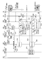
- FIG. 1 is a block diagram showing the configuration of the main part of an input device of an electronic device according to an embodiment of the present invention.
- the input device is used by the user for performing an input operation to an electronic device such as a mobile phone terminal, a portable information terminal (PDA), a portable music player, and a portable game machine. It is an assumed device.
- the input device is mounted on an electronic device, and is configured to include a touch panel having an input function by a touch operation such as touching or tracing on an input surface on a display unit.
- the input device 1 shown in FIG. 1 includes a display unit 10, a touch panel 20, a screen data holding unit 30, an application 100, a screen generation unit 200, a micro operation existence determination unit 210, a screen display control unit 300, a virtual stylus display control unit 310, An input signal analysis unit 400, a virtual stylus state management unit 410, and an input signal control unit 500 are provided.
- the application 100, the screen generation unit 200, the micro operation existence determination unit 210, the screen display control unit 300, the virtual stylus display control unit 310, the input signal analysis unit 400, the virtual stylus state management unit 410, and the input signal control unit 500 It is configured by a program executed by a control microcomputer (not shown) or a dedicated control circuit. Further, in the electronic device on which the input device 1 is mounted, a processing target 60 for performing processing such as control by the application 100 corresponding to an input operation to the input device 1 is provided.
- the processing target 60 includes various elements provided in the electronic device, such as a display unit that performs various displays, an amplifier for audio signal output, a content reproduction program, and a setting control unit that performs various settings of the device.
- the display unit 10 is a device capable of displaying various visible information such as characters, figures, and images on a flat display screen, and is configured of a liquid crystal display device or the like.
- the touch panel 20 is an input device for operation, includes a transparent sheet-like member which is disposed in a state of being superimposed on the display screen of the display unit 10 and is formed in a flat shape, and the input surface It is formed.
- the touch panel 20 has a function of an input operation unit, and periodically outputs a signal representing the presence or absence of a touch on the input surface and coordinate information of a position at which the touch is detected.
- the touch panel 20 can be configured using various detection elements such as a pressure-sensitive type and an electrostatic type, as long as they can detect the presence or absence of contact and the coordinates of the input position at which the contact is made.
- the user can touch a specific position on the touch panel 20 (a position where an object such as an operation button is displayed) while confirming the content of the display screen of the display unit 10 with light transmitted through the touch panel 20. .
- the screen data holding unit 30 holds screen data of various objects to be displayed on the display screen of the display unit 10.
- the type, content, display position and size (X direction and Y direction) related to the operation object to be operated such as an operation button operable by the user, or another display object, etc. It contains information that represents the width etc.).
- the application 100 exchanges various data, control information, and the like between a higher-level individual application program (for example, a program providing a music reproduction function) and the input device 1 providing a function for input operation.
- a program herein, a program providing a music reproduction function
- the application 100 executes the corresponding command based on the control signal notified from the input signal analysis unit 400, and gives an instruction to the processing target 60 and the screen generation unit 200.
- the screen generation unit 200 is instructed to switch the display screen.
- the screen generation unit 200 generates screen display information of a display screen in which objects of various items displayed as visible information on the display screen of the display unit 10 are combined.
- an icon representing an item such as an operation button or a slide bar to which various functions required when the user operates the application software, or a selectable content (for example, a photo) And the like, and an operation object to be operated, and a display object such as an image existing only for display such as a background.
- the operation object functions as a first operation input unit capable of performing input operation via the touch panel 20.
- the screen generation unit 200 generates and outputs screen display information of a display screen using screen data including information such as a button and a layout displayed on each screen held and managed in the screen data holding unit 30.
- the screen generation unit 200 and the screen data holding unit 30 display at least one operation object representing an operation target portion for instructing execution of a predetermined function via the input operation unit on the display unit as visible information. Implement the function of the operation object display control unit.
- the micro operation presence / absence determination unit 210 determines the screen display information of the display screen by the screen switching notification output from the screen generation unit 200, and the operation object of the operation target item which is difficult to operate directly with the user's finger in the display screen Is identified (eg, whether a small operation is required). Specifically, it includes one or more operation objects of the operation target whose width or area in the X direction or Y direction of the displayed area (or the operation target area) is smaller than a predetermined threshold (constant). In the case where the direct operation with the finger is not easy (high difficulty or difficulty), it is identified as the direct operation with the finger is easily possible otherwise.
- the micro-operation presence / absence determination unit 210 notifies the virtual stylus display control unit 310 of the identification result.
- the virtual stylus display control unit 310 generates display information of the virtual stylus when it is determined that the direct operation by the finger is not easy based on the identification result from the micro operation presence / absence determination unit 210. At this time, based on the information of the operation position notified from the input signal control unit 500, it is determined at which position the virtual stylus is to be displayed.
- the virtual stylus in this embodiment functions as a pointer used to indirectly operate the operation object displayed on the screen, and is a virtual input member replacing a stylus pen or the like. is there. This virtual stylus can realize the same function as the operation using a stylus pen or the like.
- the virtual stylus (pointer) functions as a second operation input unit capable of performing an input operation on the operation object through the touch panel 20.
- the virtual stylus display control unit 310 and the micro operation existence determination unit 210 display, as visible information, a pointer movable on the display screen for inputting an instruction to the operation object via the input operation unit on the display unit. Implement the function of the pointer display control unit.
- the screen display control unit 300 combines the screen display information of the display screen generated by the screen generation unit 200 and the display information of the virtual stylus notified from the virtual stylus display control unit 310 in real time. Display data is generated and output to the display unit 10.
- the input signal control unit 500 controls reception of a signal output from the touch panel 20 which is an input device. Specifically, it is identified whether the signal input from the touch panel 20 is noise or not, and when an appropriate signal not noise is detected, the input position on the input surface is detected, and the presence or absence of a touch and the coordinates of the touched position are detected. Is notified to the input signal analysis unit 400 and the virtual stylus display control unit 310 at regular intervals.
- the input signal control unit 500 implements a function of an input control unit that instructs processing based on an input signal of the input operation unit.
- the input signal analysis unit 400 analyzes the information input from the input signal control unit 500 to associate the content of the user's input operation with the command assigned in advance, and performs control for instructing execution of the corresponding command.
- the signal is output to the application 100. Specifically, an operation state (contact on) corresponding to a simple button press, an operation state (contact off) indicating that the button is released, a movement trajectory (contact position) when the touch position is moved while pressing Operation contents such as displacement) and coordinates (input coordinates) of these operation positions are detected.
- the analysis result of the input signal analysis unit 400 is input to the processing target 60 and the screen generation unit 200 via the application 100.
- the input signal analysis unit 400 manages related information between the display position of each operable operation object on each screen and the function assigned to the operation object, and the input operation to the touch panel 20 and the function to be executed are , Can be associated by the input position.
- the virtual stylus state management unit 410 manages the display position and the operation state of the virtual stylus, and determines whether the information of the input operation notified from the input signal control unit 500 is an operation for the virtual stylus.
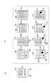
- FIG. 2 is a view showing an example of display contents of a display screen in the input device of the present embodiment.
- various specific examples of the display screen displayed on the display unit 10 are shown.
- the display screen 11A shown in FIG. 2 (a) represents an example that conforms to the condition that allows the micro operation presence / absence determination unit 210 to easily identify that a direct operation with a finger is possible, and each display shown in FIG. 2 (b)
- the display screens 11B to 11I represent an example that conforms to the condition that the direct operation by the finger is not easy.
- the operation objects 12 of the three operation buttons to which the functions of the operation buttons are respectively assigned are displayed in relatively large sizes. In this case, when the user touches and operates the touch panel 20, fine positioning is unnecessary, and each operation object 12 can be operated relatively easily with a finger.
- the display screens 11B, 11D, and 11F in FIG. 2B include a small button 12a and a large button 12b as operation objects, and the display screen 11H includes a large button 12b and an elongated slider 12c. It is included.
- the finger Direct operation at is difficult. That is, in the case of a button 12a or the like smaller than the size of a finger touching the touch panel 20, if the position of the finger is not exactly aligned with the display position of each button, another adjacent button may be touched.
- the button or the like is hidden by the finger itself, and it is difficult to recognize the display content of the screen from the user's eyes, so that it is difficult to position the operation position.
- the minute operation presence / absence determination unit 210 uses a finger. Judge that direct operation is not easy. Based on the identification result, the virtual stylus 13 is displayed by the control of the virtual stylus display control unit 310 as in the display screens 11C, 11E, 11G, and 11I of FIG. In the example of FIG. 2, the virtual stylus 13 is configured of a relatively large circular main area 13a and a thin projection area 13b protruding from a part of the main area 13a.
- the display position of the virtual stylus 13 is a virtual stylus display control unit 310 so that the display position is not overlapped with the display positions of the buttons 12a and 12b as in the display screen 11C, 11E, 11G, and 11I in the initial state.
- the virtual button 13 is located near a small button corresponding to the display condition of the virtual stylus 13 or a button whose operation position is hidden by the user's finger and at a position where no operation object is displayed.
- the stylus 13 is displayed.
- the user performs one-hand operation, it is virtually within a range (position within a predetermined radius from the fulcrum of the base of the finger assumed at the time of use) to which the thumb of the hand holding the electronic device can easily reach
- the stylus 13 may be displayed.
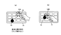
- FIG. 3 is a diagram showing a specific example of the user's operation procedure on the display screen in the input device of the present embodiment.
- an indirect input operation as shown in FIG. 3 is possible.
- the virtual stylus 13 is acquired.
- the display of the virtual stylus 13 moves in accordance with the operation of the finger.
- the tip position of the projection area 13b of the virtual stylus 13 is assigned as the operation position, and the projection area 13b is made to match the operation object 12 of the target item.
- the position touched by the user's finger is the operation position, and the operation object 12 coincident with this position is It becomes an operation target.
- the virtual stylus 13 when the user performs an indirect operation using the virtual stylus 13 (in the case of an indirect operation on the operation object at the position of the virtual stylus), the virtual stylus 13 slightly deviates from the position touched by the user's finger.
- the position of the projection area 13b is the operation position, and the operation object 12 coincident with this position is the operation target.
- the input signal corresponding to the operation object 12 of operation object is input also by any input operation of direct operation and indirect operation.
- the virtual stylus 13 since the projection area 13b is thin, accurate positioning is possible and the finger moving the virtual stylus 13 does not hide the projection area 13b, so it is suitable for operating the small button 12a. There is. Therefore, by making the virtual stylus 13 available, the operability when operating a small operation object on the screen can be improved.
- FIG. 4 is a sequence diagram showing an operation related to display control of the virtual stylus in the input device of the first embodiment.
- a screen display instruction is generated in the process of the application 100 (S11)
- this is notified to the screen generation unit 200, and the screen generation unit 200 generates screen display information of an appropriate display screen (S12).
- the screen display information is generated from screen data including information such as the type and content of the operation object and the display object held in the screen data holding unit 30, and the display position and size.
- the screen display information generated by the screen generation unit 200 is notified to the screen display control unit 300 (S13). Further, the screen generation unit 200 sends a screen switching notification to the micro operation existence determination unit 210 (S14).
- the micro operation presence / absence determination unit 210 executes micro operation presence / absence determination on the display screen (S15).
- the micro operation presence / absence determination unit 210 can not easily operate the operation object with the finger directly depending on whether or not a small operation object exists (detailed operation To determine if If it is determined that the direct operation is not easy, the micro operation presence / absence determination unit 210 determines the information indicating that the detailed operation using the virtual stylus is necessary and the information representing the optimal display position of the virtual stylus as a determination result. It notifies the stylus display control unit 310 (S16). The optimum display position is selected from among the areas where the operation object displayed on the screen does not exist.
- the virtual stylus display control unit 310 displays the display information regarding the virtual stylus at its initial display position Together with the information on the screen display control unit 300 (S17).
- the screen display control unit 300 generates a screen in which the screen display information notified from the screen generation unit 200 and the display information of the virtual stylus notified from the virtual stylus display control unit 310 are synthesized in real time (S18).
- the display data is sent to the display unit 10.
- a display completion notification is sent to the application 100.
- the display unit 10 displays a display screen including the operation object combined with the virtual stylus (S19).
- FIG. 5 is a sequence diagram showing an operation related to input operation acceptance in a virtual stylus display state in the input device of the first embodiment.
- the operation detection signal SG1 including coordinate information indicating the input position on the touch panel 20 is an input signal control unit 500. Is output in a fixed cycle.
- the input signal control unit 500 removes noise from the operation detection signal SG1 output from the touch panel 20 and provides only valid information to the input signal analysis unit 400 as an operation signal SG2.
- the virtual stylus state management unit 410 transmits the virtual stylus The state of 13 is inquired (S21).
- the virtual stylus state management unit 410 manages the state of the virtual stylus 13 as the “initial state” immediately after the virtual stylus 13 is switched from the non-display to the display state.
- the virtual stylus state management unit 410 Upon receiving a state inquiry from the input signal analysis unit 400, the virtual stylus state management unit 410 returns a state signal indicating the "initial state" to the input signal analysis unit 400, and at the same time, the management state of the virtual stylus 13 is from the "initial state". It switches to "moving state" (S22).
- the input signal analysis unit 400 determines whether the user operates the virtual stylus 13 (S23).
- the input signal analysis unit 400 checks the magnitude of the distance between the coordinates of the position at which the user touches the touch panel 20 and the center position of the virtual stylus 13 displayed on the display unit 10, whereby the user can It is determined whether the operation has been performed for 13.
- the input signal analysis unit 400 gives the position coordinates of the latest operation signal SG2 to the virtual stylus display control unit 310 as a virtual stylus coordinate position (S24).
- the virtual stylus display control unit 310 generates new display information in which the position of the virtual stylus 13 displayed on the screen is corrected using the latest virtual stylus coordinate position input from the input signal analysis unit 400, and this display information Are given to the screen display control unit 300 (S25).
- the screen display control unit 300 combines the screen display information including the operation object generated in advance with the display information of the latest virtual stylus input from the virtual stylus display control unit 310, and displays the display data of the latest screen. It gives to the display unit 10 (S26). Then, the display unit 10 displays the display screen combined with the movement of the virtual stylus according to the operation position (S27).
- the input signal analysis unit 400 determines whether the same operation continues (S28). At this time, it is determined whether the state in which the user's finger is in contact with the touch panel 20 is maintained. If the same operation continues, the virtual stylus coordinate position given to the virtual stylus display control unit 310 is updated to the latest information. Accordingly, display information indicating the latest virtual stylus coordinate position output from virtual stylus display control unit 310 is updated, and screen display control unit 300 displays the screen display information including the operation object and the latest virtual stylus. Information is synthesized (S29). Then, a display screen in which the position of the virtual stylus is further moved by the continuous operation is displayed on the display unit 10 (S30).
- the user moves the virtual stylus 13 to the position of the operation object 12 of the target item by the operation as described above, and then, when indirectly operating the operation object 12 with the virtual stylus 13, the finger touching the touch panel 20 Is temporarily released, and immediately thereafter, the tap operation is performed so as to touch the touch panel 20 for a short time at the position of the virtual stylus 13 again.
- the input signal analysis unit 400 When receiving the operation signal SG2, the input signal analysis unit 400 performs the operation continuation determination as described above (S31). In this case, it is determined that the tap operation is not the continuation of the same operation (drag operation). When the tap operation is detected, the input signal analysis unit 400 again inquires of the management state of the virtual stylus 13 to the virtual stylus state management unit 410 (S32), and the state signal from the virtual stylus state management unit 410 is "moving state" If there is, command analysis is executed (S33). That is, when the tap operation is performed after the virtual stylus 13 moves, it is regarded as an indirect operation using the virtual stylus 13, and the coordinates of the display position of the projection area 13b are set as the operation position.
- the input signal analysis unit 400 notifies the information related to the command or operation item corresponding to the application 100 so as to execute the command associated with the item of the operation position.
- the user can indirectly operate the operable items corresponding to the operation object 12 using the virtual stylus 13 it can.
- the operation position is designated by the projection area 13 b of the virtual stylus 13
- accurate alignment of the operation position in the minute area can be easily performed. Therefore, operability and operation efficiency can be improved when the user performs an input operation using the touch panel.
- control may be performed so that the moving speed of the virtual stylus by the drag operation is slower than the operation speed of the finger.
- the shape and size of the virtual stylus displayed on the screen are constant, but this may be variable.
- the contact area when the user touches the touch panel with a finger, the shape of the contact area, etc. differ among individuals, and in the case of a thick finger or a person who strongly presses the touch panel, the contact area tends to be large. In the case of a person with a thin finger or a person operating with a finger tip, the contact area is small.
- a person with eyebrows operating with his / her finger lying down it may be an elongated oval contact area.
- the shape and size of the virtual stylus displayed according to the user's instruction such as the contact area for each user and the shape of the contact area, may be optimized so that the easiness of viewing the screen and the ease of operation become optimal for each user.
- the form may be adjusted.
- the touch area at the time of operation on the touch panel is detected, and whether the operation by the finger or the operation using a physically existing stylus is determined according to the size of the contact area to switch display / non-display of the virtual stylus. It is also good.
- the virtual stylus display as described above is performed only when it is determined that the operation is a finger operation, and the input accepting operation corresponding to the virtual stylus is performed.
- FIG. 6 is a diagram showing an example of display contents of a display screen in the input device according to the second embodiment and an operation for user operation.
- the second embodiment is a modification of the first embodiment described above.
- the configuration of the input device in the second embodiment is the same as that of FIG. 1, but the contents of the operation and control of each part are slightly changed.
- an operation different from that of the first embodiment will be mainly described.
- the case where the user performs only the indirect operation using the virtual stylus 13 is shown.
- the user touches and acquires the position of the virtual stylus 13 with a finger moves the virtual stylus 13 by a drag operation, and then moves it by a tap operation or the like.
- An instruction operation is performed on the operation object 12.
- the operation may take time and effort.
- the large button 12b on the screen including the large button 12b as in the display screen 11D of FIG. 2B since fine positioning is not necessary, direct operation with a finger is better than using the virtual stylus 13. If the position of the object 12 is touched and operated, efficient operation can be performed.
- the user can complete the target operation simply by directly touching the target operation object 12A with a finger and performing a tap operation or the like.
- the state of the virtual stylus 13 is managed, and whether to operate the virtual stylus 13 is switched according to this state. Further, processing in the case where the operation position is in the vicinity of the virtual stylus 13 is added.
- FIG. 7 is a state transition diagram showing the transition of the state of the virtual stylus displayed on the display screen.
- the virtual stylus state management unit 410 can not select an item (such as an instruction operation on the operation object 12) for the state of the virtual stylus 13 displayed on the screen. And “selectable state” in which items can be selected.
- the virtual stylus state management unit 410 manages as an “initial state” in which items can not be selected immediately after the virtual stylus 13 is displayed on the screen, and when the virtual stylus 13 is moved by the user's drag operation Switch to the "selectable state". Further, the display mode of the virtual stylus 13 is changed between the “initial state” and the “selectable state” so that the user can easily identify and grasp the difference in the state of the virtual stylus 13. For example, the display mode such as the display color or pattern or the shape of the virtual stylus is automatically switched according to the state. Then, the input signal analysis unit 400 determines the operation input according to the state of the virtual stylus, and performs the corresponding processing.
- FIG. 8 is a flowchart showing a processing procedure at the time of an input operation on the virtual stylus in the second embodiment.
- the input signal analysis unit 400 executes an operation as shown in FIG.
- step S41 the input signal analysis unit 400 determines the state ("initial state” or "selectable state") in which the virtual stylus 13 displayed on the display screen is managed by the virtual stylus state management unit 410. Determine.
- the virtual stylus state management unit 410 determines whether or not the virtual stylus 13 has moved after the previous operation (such as a tap operation). If there is no movement, the virtual stylus state management unit 410 sets the initial state. As the “possible state”, the state of the virtual stylus 13 is grasped. Then, the input signal analysis unit 400 performs the processes of steps S42 to S58 in order to receive the input operation from the user according to the determined state of the virtual stylus 13.
- step S42 the input signal analysis unit 400 determines whether the operation position such as the tap operation is an operation near the boundary of the virtual stylus 13. At this time, the boundary between the contour of the virtual stylus 13 and the operation position are closer than a predetermined distance, and it is difficult to distinguish between the indirect operation using the virtual stylus and the direct operation on the operation object (for example, the state of FIG. Determine if it is.
- step S43 the input signal analysis unit 400 accepts an operation by a finger as a direct operation, and assumes that the user operates the operation object 12 or the like displayed at a position corresponding to, for example, the central position of the contact area of the finger. And execute the corresponding processing.
- step S44 the input signal analysis unit 400 determines whether the finger movement (drag operation) is detected in the state of being in contact after the tap operation by the user is detected.
- step S44 If the finger movement operation is detected in step S44, the process proceeds to step S45.
- step S45 under control of the input signal analysis unit 400, the virtual stylus display control unit 310 moves the position of the virtual stylus 13 on the display screen in accordance with the movement of the operation position of the finger.
- step S44 when the finger movement operation is not detected in step S44, the process proceeds to step S46.
- step S46 as in step S43, the input signal analysis unit 400 accepts an operation with a finger as a direct operation, and the user operates the operation object 12 or the like displayed at a position corresponding to, for example, the central position of the contact area of the finger. Execute the corresponding processing as if it were operated.
- step S41 When the virtual stylus 13 is in the “selectable state” in step S41, the process proceeds to step S47, and the input signal analysis unit 400 determines that the operation position such as tap operation is near the boundary of the virtual stylus 13 as in step S42. Determine if it is an operation.
- step S47 If the operation position is not near the boundary of the virtual stylus 13 in step S47, it is determined that the possibility of direct operation is high, and the process proceeds to step S43. Then, the input signal analysis unit 400 accepts an operation by a finger as a direct operation, and regards the operation object 12 or the like as an operation by the user, and executes corresponding processing.
- step S48 the input signal analysis unit 400 determines whether the finger movement (drag operation) is detected in the state of being in contact after the tap operation by the user is detected. .
- step S49 the input signal analysis unit 400 receives an operation by a finger as an indirect operation using the virtual stylus 13. That is, the operation object 12 or the like displayed at a position corresponding to the tip position of the projection area 13b of the virtual stylus 13 on the screen operated by the finger is regarded as being operated by the user, and the corresponding processing is executed.
- step S48 the process proceeds to step S50, and the input signal analysis unit 400 determines the movement direction of the operation.
- the movement direction is determined whether or not the movement direction is directed to the center of the virtual stylus 13. Then, when the movement direction is directed to the central portion of the virtual stylus 13, step S51 or S53 is executed according to the subsequent operation.
- step S51 if the operation after movement is the release of the finger (the operation of releasing the finger from the touch panel 20) (step S51), the process proceeds to step S52, and the input signal analysis unit 400 performs the virtual stylus operation with the finger as in step S49. Accept as an indirect operation using 13. Then, processing corresponding to the operation position is performed.
- step S53 If the drag operation is continued after the movement (step S53), the process proceeds to step S54, and the input signal analysis unit 400 determines the position of the virtual stylus 13 on the display screen as the operation position of the finger as in step S45. Move along with the movement.
- step S55 or S57 is executed in accordance with the operation at that time.
- step S55 when the release operation is detected after moving to the button (operation object 12) side near the operation position (step S55), the process proceeds to step S56, and the input signal analysis unit 400 performs the same as step S43. Accepts finger operations as direct operations. Then, processing corresponding to the operation position is performed.
- step S57 When the release operation is detected after moving in a direction other than the button (operation object 12) near the operation position (step S57), the process proceeds to step S58, and the input signal analysis unit 400 performs the current operation itself. Cancel the acceptance of the operation itself as there was no such thing, so that nothing is reacted.
- FIG. 9 is a sequence diagram showing an operation related to input operation acceptance in the virtual stylus display state in the input device of the second embodiment.
- the input signal analysis unit 400 performs virtual stylus operation determination based on the state of the operation signal SG2 input from the input signal control unit 500 (S61). Here, it is determined whether the drag operation is continued, that is, whether the drag operation is continued or another tap operation is detected.
- the input signal analysis unit 400 inquires of the virtual stylus state management unit 410 about the management state of the virtual stylus 13 (S62), and the response (initial state or selectable state) To get Thereafter, the “misoperation prevention determination process” is performed (S63).
- the “misoperation prevention determination process” corresponds to the process of FIG. 8 described above.
- the input signal analysis unit 400 specifies the operation position according to the direct operation or the indirect operation, and executes the corresponding processing.
- command analysis corresponding to the operation position is executed (S64).
- the input signal analysis unit 400 determines that the specific item (such as the operation object 12) displayed at the position coincident with the operation position is operated by the user, and is associated with the item of the operation position. Information on a command or an operation item corresponding to the application 100 is notified to execute the command.
- FIG. 10 is a schematic view showing the difference in the operation position according to the determination result of the direct operation or the indirect operation.
- the operation position to be operated is
- the judgment result of the erroneous operation prevention judgment processing differs depending on whether the direct operation or the indirect operation. That is, when it is determined that the indirect operation is performed using the virtual stylus 13, as shown in FIG. 10 (b), the tip position (P2) of the projection area 13b of the virtual stylus 13 is the coordinate position of the operation target (operation position ).
- the position (P1) at which the operation by the finger 14 is detected becomes the operation position as it is.
- the user selectively uses the direct operation in which the position of his finger is the designated point (operation position) of the operation target and the indirect operation in which the position indicated by the virtual stylus is the operation position.
- Can since state management is performed by distinguishing the "initial state” in which items can not be selected and the "selectable state in which items can be selected” as the state of the virtual stylus, it is possible to suppress the occurrence of erroneous operations not intended by the user. it can. At this time, the user can easily identify the state of the virtual stylus by the display mode of the virtual stylus.
- FIG. 11 is a diagram showing an example of display contents of a display screen in the input device according to the third embodiment and an operation for user operation.
- the third embodiment is another modification of the first embodiment described above.
- the configuration of the input device in the third embodiment is the same as that of FIG. 1, but the contents of the operation and control of each part are slightly changed.
- an operation different from that of the first embodiment will be mainly described.
- the pen-like virtual stylus 13 whose shape is fixed is displayed on the screen as a pointer for the user to perform an indirect operation. It is possible to notify the user of the difference in operating conditions and the like, and to improve the operability. It is also possible to add an amusement-like element in the display of the virtual stylus. Therefore, in the third embodiment, a character pattern whose shape such as shape can be changed is used as a pointer instead of the virtual stylus 13 described above.
- a character pattern such as an insect is displayed as the pointer 50 and displayed.
- a plurality of patterns of pointers 50a and 50b having different directions are used according to the situation.
- the pointer 50 when the user performs a drag operation with the finger 14, the pointer 50 performs an animation display such as "hurrying to follow the finger" slightly behind the movement of the finger 14. It is also possible.
- the pointer 50 when displaying the pointer 50 of the character pattern, the pointer 50 may be displayed so as to move slowly on the display screen. This can prevent the operation object on the display screen from being obscured or obscured by the pointer.
- selection indications 51a and 51b are provided in addition to the pointer 50, and display is performed so as to surround the operation object 12 selected by the pointer 50 to change the pointer pattern.
- Selection items, selection states, and the like can be easily identified by the user.
- the pointer 50 is moved within a range that does not impair operability, such as moving around the operation object 12 of the selection item. It is also possible to perform such animation display.
- FIG. 12 is a sequence diagram showing an operation related to input operation acceptance in the pointer display state in the input device of the third embodiment.
- the virtual stylus state management unit 410 has a function of managing the state of the pointer 50 instead of the virtual stylus 13, and the contents of the process are the first except for the name of the management target. Basically the same as the embodiment of FIG.
- the virtual stylus state management unit 410 receives The state is inquired (S71).
- the virtual stylus state management unit 410 manages the state of the pointer 50 as the “initial state” immediately after the pointer 50 is switched from the non-display to the display state.
- the virtual stylus state management unit 410 Upon receiving a state inquiry from the input signal analysis unit 400, the virtual stylus state management unit 410 returns a state signal indicating the "initial state" to the input signal analysis unit 400, and at the same time, the management state of the virtual stylus 13 is from the "initial state”. It switches to "moving state" (S72).
- the input signal analysis unit 400 determines whether the user is operating the pointer 50 (S73). Here, the input signal analysis unit 400 checks the distance between the coordinates of the position at which the user touches the touch panel 20 and the center position of the pointer 50 displayed on the display unit 10, thereby allowing the user to make the pointer 50 Determine if you operated against.
- the input signal analysis unit 400 gives the position coordinate of the latest operation signal SG2 to the virtual stylus display control unit 310 as a pointer coordinate position (S74).
- the virtual stylus display control unit 310 generates new display information in which the position of the pointer 50 to be displayed on the screen is corrected using the latest pointer coordinate position input from the input signal analysis unit 400, and displays this display information It gives to the display control unit 300 (S75).
- the screen display control unit 300 combines the screen display information including the operation object generated in advance with the display information of the latest pointer input from the virtual stylus display control unit 310, and displays the display data of the latest screen. It gives to the part 10 (S76). Then, the display unit 10 displays the display screen combined with the movement of the pointer according to the operation position (S77).
- the character of the displayed pointer 50 moves slightly behind the finger 14 so that it is slightly before the position coordinates of the operation signal SG2 representing the position of the finger 14 Assign the pointer coordinate position to the shifted position.
- a display is performed such that the character follows behind toward the placement position of the finger.
- the input signal analysis unit 400 receives from the input signal control unit 500 an operation signal SG2 indicating that the finger 14 has been released from the touch panel 20 after detecting the movement operation (drag operation) of the pointer 50, the timer is activated. It waits for a predetermined time (S78). Then, after a predetermined time has elapsed, a display switching signal SG3 regarding the display mode of the pointer 50 is supplied to the virtual stylus display control unit 310.
- the virtual stylus display control unit 310 When the virtual stylus display control unit 310 receives the display switching signal SG3 from the input signal analysis unit 400, the virtual stylus display control unit 310 generates an image for specifying the operation target item (the operation object 12 or the like of the operation target) (S79). In this case, for example, an image to which the selection display 51a, 51b as shown in FIG. 11C is added is generated.
- the screen display control unit 300 combines the screen display information including the operation object with the display information of the pointer added with the display for specifying the selection item (S80). Then, a display screen including the pointer 50 to which the selection display 51a, 51b is added is displayed on the display unit 10 (S81). As a result, in a state of waiting for the input of the selection operation of the operation object 12 after the movement operation of the pointer 50, such a display as explicitly indicating the item of the operation object 12 specified by the selection display 51a, 51b is performed. .
- movement from a change in display mode such as the form of the pointer is performed by animating the pointer as a character pattern or adding a selective display for specifying a selection item after the movement of the pointer.
- the user can intuitively grasp the current operation state such as and selection, and efficient input operation becomes possible using the pointer.
- it is possible to add an amusement-like element to the display of the pointer to improve the usability.
- the present invention is not limited to those described in the above embodiments, but may be modified or applied by those skilled in the art based on the description of the specification and well-known techniques. Yes, within the scope of seeking protection.
- the present invention is advantageous in that when the user performs an input operation using a touch panel, operability can be improved even when the operation target is small, etc., and the user can perform efficient input operation in various situations.
- an input device of an electronic device that can be used for an input operation in an electronic device such as a mobile phone terminal, a portable information terminal (PDA), a portable music player, and a portable game machine.
Landscapes
- Engineering & Computer Science (AREA)
- General Engineering & Computer Science (AREA)
- Theoretical Computer Science (AREA)
- Human Computer Interaction (AREA)
- Physics & Mathematics (AREA)
- General Physics & Mathematics (AREA)
- User Interface Of Digital Computer (AREA)
- Position Input By Displaying (AREA)
Abstract
Description
これにより、表示画面上に表示されている操作オブジェクトの情報に応じて、表示画面上に表示されている操作オブジェクトの表示領域あるいは入力操作を受け付ける領域の幅または面積が所定値以下である場合に、ポインタを表示することで、ユーザはポインタによって操作オブジェクトに対する操作が可能となる。この場合、操作オブジェクトが小さくてタッチパネルでの直接操作が容易でない状態においてポインタによる間接操作が可能となり、操作性を向上させることができる。したがって、表示画面の状況に応じて必要な場合にポインタを表示させて利用可能にすることができ、操作効率や利便性を改善できる。 An input device of an electronic device according to the present invention includes a display unit capable of displaying visible information related to an input operation, and an input operation unit having a touch panel having an input function by a touch operation on an input surface corresponding to a display screen of the display unit. An input control unit for instructing processing based on an input signal of the input operation unit; and at least one operation object representing an operation target portion for instructing execution of a predetermined function via the input operation unit; An operation object display control unit displayed on the display unit as information and a pointer movable on a display screen for inputting an instruction to the operation object via the input operation unit are displayed on the display unit as the visible information Function to display or hide the pointer according to the information of the operation object displayed on the display unit A pointer display control unit for displaying the pointer when the width or area of the display area of the operation object displayed on the display unit or the area for receiving an input operation is less than or equal to a predetermined value as the information of the operation object; , Is provided.
Thereby, according to the information of the operation object displayed on the display screen, when the width or area of the display area of the operation object displayed on the display screen or the area for receiving the input operation is equal to or less than a predetermined value. By displaying the pointer, the user can operate the operation object by the pointer. In this case, in a state where the operation object is small and direct operation on the touch panel is not easy, indirect operation by the pointer becomes possible, and operability can be improved. Therefore, the pointer can be displayed and made available when necessary according to the condition of the display screen, and the operation efficiency and convenience can be improved.
これにより、入力操作部の入力面における接触操作時の接触面積が所定値以上である場合に、ユーザが指によってタッチパネルを操作しているものとみなし、ポインタを表示してポインタによる間接操作が可能となる。また、接触面積が所定値未満の場合は、ユーザが先端の細いスタイラスなどで操作しているものとみなし、ポインタを非表示とすることができ、不必要なポインタ表示を抑止できる。このように、必要に応じてポインタの表示/非表示を切り替えることができる。 Further, according to the present invention, in the input device of the electronic device, the pointer display control unit is configured to receive the pointer when the contact area at the time of the touch operation on the input surface of the input operation unit is a predetermined value or more. Including what is displayed.
Thereby, when the contact area at the time of touch operation on the input surface of the input operation unit is equal to or more than a predetermined value, it is considered that the user is operating the touch panel with a finger, and the pointer is displayed to enable indirect operation by the pointer It becomes. If the contact area is less than a predetermined value, it can be regarded that the user is operating with a thin stylus or the like at the tip, the pointer can be hidden, and unnecessary pointer display can be suppressed. In this way, it is possible to switch the display / non-display of the pointer as needed.
これにより、ポインタ表示の初期状態などでポインタを操作オブジェクトなどの表示や操作の妨げにならない適切な位置に表示可能となる。 Further, in the input device of the electronic device according to the present invention, the pointer display control unit may display the pointer in the vicinity of the area including the operation object corresponding to the display condition of the pointer. A position where the display position of the pointer does not overlap the operation object is included.
As a result, in the initial state of pointer display, the pointer can be displayed at an appropriate position that does not interfere with the display of the operation object or the operation.
これにより、操作オブジェクトに対する直接操作と、ポインタを用いた操作オブジェクトへの間接操作との両方を行うことができるので、状況に応じて間接操作と直接操作とを使い分けることが可能になる。このため、様々な状況においてユーザの効率的な入力操作が可能になり、操作効率を改善できる。 Further, the present invention is the input device of the electronic device described above, wherein the input control unit is configured to directly receive the operation object on the display screen as an input operation corresponding to the display screen of the display unit by the input operation unit. It includes those which can receive an input signal by any input operation of an operation and an indirect operation to the operation object at the position of the pointer.
As a result, since both direct operation on the operation object and indirect operation on the operation object using the pointer can be performed, it is possible to selectively use the indirect operation and the direct operation depending on the situation. For this reason, efficient input operation of a user is attained in various situations, and operation efficiency can be improved.
これにより、ポインタに対する入力操作の状況によって、ポインタによる間接操作の有効/無効の各状態を切り替えることができ、ユーザが意図しない誤操作の発生を抑止できる。 Further, the present invention is the input device of the electronic device described above, wherein the pointer display control unit invalidates the indirect operation on the operation object by the pointer when displaying the pointer. And a second state in which the indirect operation on the operation object by the pointer is enabled, and the first state and the second state are switched according to the detection situation of the input operation on the pointer Including things.
As a result, it is possible to switch between the valid / invalid states of the indirect operation by the pointer according to the state of the input operation on the pointer, and to suppress the occurrence of an erroneous operation not intended by the user.
これにより、ポインタの状態を容易に識別できるようになり、誤操作の発生を防止でき、視認性や操作性を向上できる。 Further, the present invention is the input device of the above-mentioned electronic device, wherein the pointer display control unit switches and displays the display mode of the pointer in the first state and the second state. .
Thus, the state of the pointer can be easily identified, the occurrence of an erroneous operation can be prevented, and the visibility and operability can be improved.
これにより、ポインタの状態や操作オブジェクトの選択状態を容易に識別できるようになり、視認性や操作性を向上できる。 Further, according to the present invention, in the input device of the electronic device described above, when the pointer is in the second state, the pointer display control unit operates the pointer at or near the display position of the pointer using the pointer. Includes adding a selection indicator to indicate that it has been selected.
As a result, the state of the pointer and the selection state of the operation object can be easily identified, and the visibility and operability can be improved.
これにより、ポインタの形態の変化から、移動等の現在の操作状態をユーザが直感的に把握することができ、ポインタを用いて効率的な入力操作が可能になる。また、ポインタの表示にアミューズメント的な要素を持たせ、使用感を向上させることも可能である。 The present invention also includes the input device of the electronic device described above, wherein the pointer display control unit uses a character pattern whose form can be changed as the pointer, and displays the character pattern in an animation.
This allows the user to intuitively grasp the current operation state such as movement from the change in the form of the pointer, and enables efficient input operation using the pointer. In addition, it is possible to add an amusement-like element to the display of the pointer to improve the usability.
これにより、ユーザ毎の接触面積や接触領域の形状などに応じて、適切な形態のポインタを表示することができ、視認性や操作性を向上できる。 Further, the present invention is the input device of the above electronic device, wherein the pointer display control unit is configured and sized according to the form of the contact area at the time of the touch operation on the input surface of the input operation unit. Change the form including at least one of the
Thus, a pointer of an appropriate form can be displayed according to the contact area of each user, the shape of the contact area, and the like, and visibility and operability can be improved.
11、11A~11M 表示画面
12 操作オブジェクト
13 仮想スタイラス
13a 主領域
13b 突起領域
14 指
20 タッチパネル
30 画面データ保持部
50 ポインタ
51a,51b 選択表示
60 処理対象
100 アプリケーション
200 画面生成部
210 微小操作有無判定部
300 画面表示制御部
310 仮想スタイラス表示制御部
400 入力信号解析部
410 仮想スタイラス状態管理部
500 入力信号制御部 DESCRIPTION OF
図1は本発明の実施形態における電子機器の入力装置の主要部の構成を示すブロック図である。 First Embodiment
FIG. 1 is a block diagram showing the configuration of the main part of an input device of an electronic device according to an embodiment of the present invention.
図6は第2の実施形態の入力装置における表示画面の表示内容及びユーザ操作に対する動作の例を示す図である。 Second Embodiment
FIG. 6 is a diagram showing an example of display contents of a display screen in the input device according to the second embodiment and an operation for user operation.
図11は第3の実施形態の入力装置における表示画面の表示内容及びユーザ操作に対する動作の例を示す図である。 Third Embodiment
FIG. 11 is a diagram showing an example of display contents of a display screen in the input device according to the third embodiment and an operation for user operation.
Claims (10)
- 入力操作に関する可視情報を表示可能な表示部と、
前記表示部の表示画面に対応する入力面への接触操作による入力機能を有するタッチパネルを有する入力操作部と、
前記入力操作部の入力信号に基づいて処理を指示する入力制御部と、
前記入力操作部を介して所定の機能の実行を指示するための操作対象部位を表す少なくとも1つの操作オブジェクトを前記可視情報として前記表示部に表示する操作オブジェクト表示制御部と、
前記入力操作部を介して前記操作オブジェクトに対する指示入力を行うための表示画面上で移動可能なポインタを前記可視情報として前記表示部に表示する機能を有し、前記表示部に表示している操作オブジェクトの情報に応じて前記ポインタを表示または非表示とするもので、前記操作オブジェクトの情報として、前記表示部に表示している操作オブジェクトの表示領域あるいは入力操作を受け付ける領域の幅または面積が所定値以下である場合に、前記ポインタを表示させるポインタ表示制御部と、
を備える電子機器の入力装置。 A display unit capable of displaying visible information on an input operation;
An input operation unit having a touch panel having an input function by a touch operation on an input surface corresponding to a display screen of the display unit;
An input control unit that instructs processing based on an input signal of the input operation unit;
An operation object display control unit which displays at least one operation object representing an operation target portion for instructing execution of a predetermined function via the input operation unit as the visible information on the display unit;
An operation having a function of displaying a pointer movable on the display screen for inputting an instruction to the operation object via the input operation unit as the visible information on the display unit, the operation being displayed on the display unit The pointer is displayed or not displayed according to the information of the object, and the width or area of the display area of the operation object displayed on the display unit or the area for receiving an input operation is predetermined as the information of the operation object A pointer display control unit for displaying the pointer when the value is less than or equal to a value;
An input device of an electronic device comprising: - 請求項1に記載の電子機器の入力装置であって、
前記ポインタ表示制御部は、前記入力操作部の入力面における接触操作時の接触面積が所定値以上である場合に、前記ポインタを表示させる電子機器の入力装置。 An input device of the electronic device according to claim 1, wherein
The input device for an electronic device that causes the pointer display control unit to display the pointer when the contact area at the time of touch operation on the input surface of the input operation unit is equal to or more than a predetermined value. - 請求項1に記載の電子機器の入力装置であって、
前記ポインタ表示制御部は、前記ポインタを表示させる場合に、前記ポインタの表示条件に該当する操作オブジェクトを含む領域の近傍で、前記操作オブジェクトに重ならない位置を前記ポインタの表示位置とする電子機器の入力装置。 An input device of the electronic device according to claim 1, wherein
When the pointer display control unit causes the pointer to be displayed, the pointer display control unit sets, as a display position of the pointer, a position not overlapping the operation object in the vicinity of the area including the operation object corresponding to the display condition of the pointer. Input device. - 請求項1に記載の電子機器の入力装置であって、
前記入力制御部は、前記入力操作部による前記表示部の表示画面に対応する入力操作として、表示画面上の前記操作オブジェクトに対する直接操作と、前記ポインタの位置における前記操作オブジェクトへの間接操作とのいずれの入力操作による入力信号も受付可能である電子機器の入力装置。 An input device of the electronic device according to claim 1, wherein
The input control unit performs, as an input operation corresponding to the display screen of the display unit by the input operation unit, a direct operation on the operation object on the display screen and an indirect operation on the operation object at the position of the pointer. An input device of an electronic device capable of accepting an input signal by any input operation. - 請求項4に記載の電子機器の入力装置であって、
前記ポインタ表示制御部は、前記ポインタを表示する際に、前記ポインタによる前記操作オブジェクトへの間接操作を無効とする第1の状態と、前記ポインタによる前記操作オブジェクトへの間接操作を有効とする第2の状態とを設定し、前記ポインタに対する入力操作の検出状況に応じて前記第1の状態と前記第2の状態とを切り替える電子機器の入力装置。 It is an input device of the electronic device according to claim 4,
When displaying the pointer, the pointer display control unit validates the first state in which the indirect operation on the operation object by the pointer is invalidated, and the indirect operation on the operation object by the pointer is effective. An input device of an electronic device which sets the second state and switches between the first state and the second state in accordance with a detection state of an input operation to the pointer. - 請求項5に記載の電子機器の入力装置であって、
前記ポインタ表示制御部は、前記第1の状態と前記第2の状態とで前記ポインタの表示態様を切り替えて表示させる電子機器の入力装置。 An input device of the electronic device according to claim 5, wherein
The input device for an electronic device, wherein the pointer display control unit switches and displays the display mode of the pointer between the first state and the second state. - 請求項5に記載の電子機器の入力装置であって、
前記ポインタ表示制御部は、前記ポインタが前記第2の状態の場合に、このポインタの表示位置またはその近傍の操作オブジェクトがポインタにより選択されたことを示す選択表示を付加する電子機器の入力装置。 An input device of the electronic device according to claim 5, wherein
The input device for an electronic device, wherein the pointer display control unit adds a selection display indicating that an operation object at or near a display position of the pointer is selected by the pointer when the pointer is in the second state. - 請求項1に記載の電子機器の入力装置であって、
前記ポインタ表示制御部は、前記ポインタとして形態を変更可能なキャラクタパターンを用い、このキャラクタパターンをアニメーション表示させる電子機器の入力装置。 An input device of the electronic device according to claim 1, wherein
The pointer display control unit uses the character pattern whose form is changeable as the pointer, and uses the character pattern as an animation to display the character pattern. - 請求項1に記載の電子機器の入力装置であって、
前記ポインタ表示制御部は、前記入力操作部の入力面における接触操作時の接触領域の形態に応じて、前記ポインタの形、大きさの少なくともいずれかを含む形態を変更する電子機器の入力装置。 An input device of the electronic device according to claim 1, wherein
The input device for an electronic device, wherein the pointer display control unit changes a form including at least one of a shape and a size of the pointer according to a form of a contact area at the time of a touch operation on an input surface of the input operation unit. - 請求項1~9のいずれかに記載の入力装置を搭載した電子機器。 An electronic device equipped with the input device according to any one of claims 1 to 9.
Priority Applications (1)
| Application Number | Priority Date | Filing Date | Title |
|---|---|---|---|
| US12/867,713 US20100328209A1 (en) | 2008-02-15 | 2008-12-04 | Input device for electronic apparatus |
Applications Claiming Priority (2)
| Application Number | Priority Date | Filing Date | Title |
|---|---|---|---|
| JP2008034330A JP2009193423A (en) | 2008-02-15 | 2008-02-15 | Input device for electronic equipment |
| JP2008-034330 | 2008-02-15 |
Publications (1)
| Publication Number | Publication Date |
|---|---|
| WO2009101665A1 true WO2009101665A1 (en) | 2009-08-20 |
Family
ID=40956712
Family Applications (1)
| Application Number | Title | Priority Date | Filing Date |
|---|---|---|---|
| PCT/JP2008/003606 WO2009101665A1 (en) | 2008-02-15 | 2008-12-04 | Input device for electronic equipment |
Country Status (3)
| Country | Link |
|---|---|
| US (1) | US20100328209A1 (en) |
| JP (1) | JP2009193423A (en) |
| WO (1) | WO2009101665A1 (en) |
Cited By (2)
| Publication number | Priority date | Publication date | Assignee | Title |
|---|---|---|---|---|
| JP2012104095A (en) * | 2010-10-15 | 2012-05-31 | Canon Inc | Information processing equipment, information processing method and program |
| US9268425B2 (en) | 2011-04-14 | 2016-02-23 | Konami Digital Entertainment Co., Ltd. | Portable device, control method thereof, and recording medium whereon program is recorded |
Families Citing this family (21)
| Publication number | Priority date | Publication date | Assignee | Title |
|---|---|---|---|---|
| JP2009245239A (en) * | 2008-03-31 | 2009-10-22 | Sony Corp | Pointer display device, pointer display/detection method, pointer display/detection program and information apparatus |
| JP5446617B2 (en) * | 2009-09-02 | 2014-03-19 | 富士ゼロックス株式会社 | Selection support apparatus and program |
| JP2011081447A (en) * | 2009-10-02 | 2011-04-21 | Seiko Instruments Inc | Information processing method and information processor |
| WO2011052261A1 (en) * | 2009-10-27 | 2011-05-05 | シャープ株式会社 | Pointing device |
| US9292161B2 (en) * | 2010-03-24 | 2016-03-22 | Microsoft Technology Licensing, Llc | Pointer tool with touch-enabled precise placement |
| KR20120023867A (en) * | 2010-09-02 | 2012-03-14 | 삼성전자주식회사 | Mobile terminal having touch screen and method for displaying contents thereof |
| US8959013B2 (en) * | 2010-09-27 | 2015-02-17 | Apple Inc. | Virtual keyboard for a non-tactile three dimensional user interface |
| KR101718893B1 (en) * | 2010-12-24 | 2017-04-05 | 삼성전자주식회사 | Method and apparatus for providing touch interface |
| US9317196B2 (en) | 2011-08-10 | 2016-04-19 | Microsoft Technology Licensing, Llc | Automatic zooming for text selection/cursor placement |
| US9310941B2 (en) * | 2011-10-04 | 2016-04-12 | Atmel Corporation | Touch sensor input tool with offset between touch icon and input icon |
| CN103988159B (en) * | 2011-12-22 | 2017-11-24 | 索尼公司 | Display control unit and display control method |
| JP5962085B2 (en) * | 2012-03-15 | 2016-08-03 | ソニー株式会社 | Display control apparatus, control method thereof, and program |
| US9348501B2 (en) | 2012-06-14 | 2016-05-24 | Microsoft Technology Licensing, Llc | Touch modes |
| KR102086799B1 (en) * | 2013-02-21 | 2020-03-09 | 삼성전자주식회사 | Method for displaying for virtual keypad an electronic device thereof |
| US9483549B2 (en) * | 2013-09-30 | 2016-11-01 | Microsoft Technology Licensing, Llc | Persisting state at scale across browser sessions |
| JP6260255B2 (en) * | 2013-12-18 | 2018-01-17 | 株式会社デンソー | Display control apparatus and program |
| JP6525753B2 (en) | 2015-06-12 | 2019-06-05 | キヤノン株式会社 | Display control device, control method thereof, and program |
| JP2017068797A (en) * | 2015-10-02 | 2017-04-06 | 富士通株式会社 | Input support system and electronic apparatus |
| WO2017154119A1 (en) * | 2016-03-08 | 2017-09-14 | 富士通株式会社 | Display control device, display control method, and display control program |
| US10656780B2 (en) | 2018-01-12 | 2020-05-19 | Mitutoyo Corporation | Position specifying method and program |
| JP7113625B2 (en) * | 2018-01-12 | 2022-08-05 | 株式会社ミツトヨ | Positioning method and program |
Citations (6)
| Publication number | Priority date | Publication date | Assignee | Title |
|---|---|---|---|---|
| JPH0651908A (en) * | 1992-07-28 | 1994-02-25 | Sony Corp | Information processor provided with touch panel type input device |
| JPH0683537A (en) * | 1992-09-01 | 1994-03-25 | Ricoh Co Ltd | Touch panel type information processor |
| JPH0876927A (en) * | 1994-08-31 | 1996-03-22 | Brother Ind Ltd | Information processor |
| JP2005346507A (en) * | 2004-06-03 | 2005-12-15 | Sony Corp | Portable electronic apparatus, input operation control method, and program therefor |
| WO2006027924A1 (en) * | 2004-09-03 | 2006-03-16 | Matsushita Electric Industrial Co., Ltd. | Input device |
| JP2007257371A (en) * | 2006-03-23 | 2007-10-04 | Fujitsu Ltd | Program, method and device controlling a plurality of pointers |
Family Cites Families (10)
| Publication number | Priority date | Publication date | Assignee | Title |
|---|---|---|---|---|
| KR100260760B1 (en) * | 1996-07-31 | 2000-07-01 | 모리 하루오 | Information display system with touch panel |
| US6727892B1 (en) * | 1999-05-20 | 2004-04-27 | Micron Technology, Inc. | Method of facilitating the selection of features at edges of computer touch screens |
| US6411283B1 (en) * | 1999-05-20 | 2002-06-25 | Micron Technology, Inc. | Computer touch screen adapted to facilitate selection of features at edge of screen |
| FI115254B (en) * | 2001-12-20 | 2005-03-31 | Nokia Corp | Use of touch screen with a touch screen |
| KR100539904B1 (en) * | 2004-02-27 | 2005-12-28 | 삼성전자주식회사 | Pointing device in terminal having touch screen and method for using it |
| US8044932B2 (en) * | 2004-06-08 | 2011-10-25 | Samsung Electronics Co., Ltd. | Method of controlling pointer in mobile terminal having pointing device |
| US7489306B2 (en) * | 2004-12-22 | 2009-02-10 | Microsoft Corporation | Touch screen accuracy |
| US7692629B2 (en) * | 2006-12-07 | 2010-04-06 | Microsoft Corporation | Operating touch screen interfaces |
| US8001483B2 (en) * | 2007-02-13 | 2011-08-16 | Microsoft Corporation | Selective display of cursor |
| KR20110025520A (en) * | 2009-09-04 | 2011-03-10 | 삼성전자주식회사 | Apparatus and method for controlling a mobile terminal |
-
2008
- 2008-02-15 JP JP2008034330A patent/JP2009193423A/en active Pending
- 2008-12-04 WO PCT/JP2008/003606 patent/WO2009101665A1/en active Application Filing
- 2008-12-04 US US12/867,713 patent/US20100328209A1/en not_active Abandoned
Patent Citations (6)
| Publication number | Priority date | Publication date | Assignee | Title |
|---|---|---|---|---|
| JPH0651908A (en) * | 1992-07-28 | 1994-02-25 | Sony Corp | Information processor provided with touch panel type input device |
| JPH0683537A (en) * | 1992-09-01 | 1994-03-25 | Ricoh Co Ltd | Touch panel type information processor |
| JPH0876927A (en) * | 1994-08-31 | 1996-03-22 | Brother Ind Ltd | Information processor |
| JP2005346507A (en) * | 2004-06-03 | 2005-12-15 | Sony Corp | Portable electronic apparatus, input operation control method, and program therefor |
| WO2006027924A1 (en) * | 2004-09-03 | 2006-03-16 | Matsushita Electric Industrial Co., Ltd. | Input device |
| JP2007257371A (en) * | 2006-03-23 | 2007-10-04 | Fujitsu Ltd | Program, method and device controlling a plurality of pointers |
Cited By (2)
| Publication number | Priority date | Publication date | Assignee | Title |
|---|---|---|---|---|
| JP2012104095A (en) * | 2010-10-15 | 2012-05-31 | Canon Inc | Information processing equipment, information processing method and program |
| US9268425B2 (en) | 2011-04-14 | 2016-02-23 | Konami Digital Entertainment Co., Ltd. | Portable device, control method thereof, and recording medium whereon program is recorded |
Also Published As
| Publication number | Publication date |
|---|---|
| JP2009193423A (en) | 2009-08-27 |
| US20100328209A1 (en) | 2010-12-30 |
Similar Documents
| Publication | Publication Date | Title |
|---|---|---|
| WO2009101665A1 (en) | Input device for electronic equipment | |
| JP4734435B2 (en) | Portable game device with touch panel display | |
| EP2575006B1 (en) | Touch and non touch based interaction of a user with a device | |
| JP5580694B2 (en) | Information processing apparatus, control method therefor, program, and storage medium | |
| US20170293351A1 (en) | Head mounted display linked to a touch sensitive input device | |
| CN1307518C (en) | Information display input device and information display input method, and information processing device | |
| US20110298743A1 (en) | Information processing apparatus | |
| US20140055385A1 (en) | Scaling of gesture based input | |
| WO2014050147A1 (en) | Display control device, display control method and program | |
| JP3744116B2 (en) | Display input device | |
| JP6015183B2 (en) | Information processing apparatus and program | |
| JP2019145058A (en) | Information processing device | |
| JP2018023792A (en) | Game device and program | |
| JP5769841B2 (en) | Portable game device with touch panel display | |
| JPH11126132A (en) | Input device | |
| JP6126639B2 (en) | A portable game device having a touch panel display and a game program. | |
| JP5523381B2 (en) | Portable game device with touch panel display | |
| JP2014016927A (en) | Information processing device and program | |
| KR101136327B1 (en) | A touch and cursor control method for portable terminal and portable terminal using the same | |
| JP6204414B2 (en) | GAME DEVICE AND PROGRAM | |
| JP5769765B2 (en) | Portable game device with touch panel display | |
| WO2022207821A1 (en) | A method for integrated gaze interaction with a virtual environment, a data processing system, and computer program | |
| WO2018131245A1 (en) | Information processing device, information processing method, and program | |
| JP2020163167A (en) | Game device and program | |
| KR101257889B1 (en) | Apparatus and method of user input interface for portable device |
Legal Events
| Date | Code | Title | Description |
|---|---|---|---|
| 121 | Ep: the epo has been informed by wipo that ep was designated in this application |
Ref document number: 08872346 Country of ref document: EP Kind code of ref document: A1 |
|
| WWE | Wipo information: entry into national phase |
Ref document number: 12867713 Country of ref document: US Ref document number: 5076/CHENP/2010 Country of ref document: IN |
|
| NENP | Non-entry into the national phase |
Ref country code: DE |
|
| 122 | Ep: pct application non-entry in european phase |
Ref document number: 08872346 Country of ref document: EP Kind code of ref document: A1 |