WO2005029669A2 - Active filter for multi-phase ac power system - Google Patents

Active filter for multi-phase ac power system Download PDF

Info

Publication number
WO2005029669A2
WO2005029669A2 PCT/US2004/026184 US2004026184W WO2005029669A2 WO 2005029669 A2 WO2005029669 A2 WO 2005029669A2 US 2004026184 W US2004026184 W US 2004026184W WO 2005029669 A2 WO2005029669 A2 WO 2005029669A2
Authority
WO
WIPO (PCT)
Prior art keywords
phase
current
voltage
power
controller
Prior art date
Application number
PCT/US2004/026184
Other languages
French (fr)
Other versions
WO2005029669A3 (en
Inventor
Louis Cheng
Qihua Zhao
Original Assignee
Honeywell International, Inc.
Priority date (The priority date is an assumption and is not a legal conclusion. Google has not performed a legal analysis and makes no representation as to the accuracy of the date listed.)
Filing date
Publication date
Application filed by Honeywell International, Inc. filed Critical Honeywell International, Inc.
Priority to EP04809557A priority Critical patent/EP1656723A2/en
Publication of WO2005029669A2 publication Critical patent/WO2005029669A2/en
Publication of WO2005029669A3 publication Critical patent/WO2005029669A3/en

Links

Classifications

    • HELECTRICITY
    • H02GENERATION; CONVERSION OR DISTRIBUTION OF ELECTRIC POWER
    • H02JCIRCUIT ARRANGEMENTS OR SYSTEMS FOR SUPPLYING OR DISTRIBUTING ELECTRIC POWER; SYSTEMS FOR STORING ELECTRIC ENERGY
    • H02J3/00Circuit arrangements for ac mains or ac distribution networks
    • H02J3/18Arrangements for adjusting, eliminating or compensating reactive power in networks
    • H02J3/1821Arrangements for adjusting, eliminating or compensating reactive power in networks using shunt compensators
    • H02J3/1835Arrangements for adjusting, eliminating or compensating reactive power in networks using shunt compensators with stepless control
    • H02J3/1842Arrangements for adjusting, eliminating or compensating reactive power in networks using shunt compensators with stepless control wherein at least one reactive element is actively controlled by a bridge converter, e.g. active filters
    • H02J3/185Arrangements for adjusting, eliminating or compensating reactive power in networks using shunt compensators with stepless control wherein at least one reactive element is actively controlled by a bridge converter, e.g. active filters wherein such reactive element is purely inductive, e.g. superconductive magnetic energy storage systems [SMES]
    • HELECTRICITY
    • H02GENERATION; CONVERSION OR DISTRIBUTION OF ELECTRIC POWER
    • H02JCIRCUIT ARRANGEMENTS OR SYSTEMS FOR SUPPLYING OR DISTRIBUTING ELECTRIC POWER; SYSTEMS FOR STORING ELECTRIC ENERGY
    • H02J3/00Circuit arrangements for ac mains or ac distribution networks
    • H02J3/01Arrangements for reducing harmonics or ripples
    • HELECTRICITY
    • H02GENERATION; CONVERSION OR DISTRIBUTION OF ELECTRIC POWER
    • H02MAPPARATUS FOR CONVERSION BETWEEN AC AND AC, BETWEEN AC AND DC, OR BETWEEN DC AND DC, AND FOR USE WITH MAINS OR SIMILAR POWER SUPPLY SYSTEMS; CONVERSION OF DC OR AC INPUT POWER INTO SURGE OUTPUT POWER; CONTROL OR REGULATION THEREOF
    • H02M1/00Details of apparatus for conversion
    • H02M1/12Arrangements for reducing harmonics from ac input or output
    • HELECTRICITY
    • H02GENERATION; CONVERSION OR DISTRIBUTION OF ELECTRIC POWER
    • H02MAPPARATUS FOR CONVERSION BETWEEN AC AND AC, BETWEEN AC AND DC, OR BETWEEN DC AND DC, AND FOR USE WITH MAINS OR SIMILAR POWER SUPPLY SYSTEMS; CONVERSION OF DC OR AC INPUT POWER INTO SURGE OUTPUT POWER; CONTROL OR REGULATION THEREOF
    • H02M1/00Details of apparatus for conversion
    • H02M1/14Arrangements for reducing ripples from dc input or output
    • H02M1/15Arrangements for reducing ripples from dc input or output using active elements
    • YGENERAL TAGGING OF NEW TECHNOLOGICAL DEVELOPMENTS; GENERAL TAGGING OF CROSS-SECTIONAL TECHNOLOGIES SPANNING OVER SEVERAL SECTIONS OF THE IPC; TECHNICAL SUBJECTS COVERED BY FORMER USPC CROSS-REFERENCE ART COLLECTIONS [XRACs] AND DIGESTS
    • Y02TECHNOLOGIES OR APPLICATIONS FOR MITIGATION OR ADAPTATION AGAINST CLIMATE CHANGE
    • Y02EREDUCTION OF GREENHOUSE GAS [GHG] EMISSIONS, RELATED TO ENERGY GENERATION, TRANSMISSION OR DISTRIBUTION
    • Y02E40/00Technologies for an efficient electrical power generation, transmission or distribution
    • Y02E40/20Active power filtering [APF]
    • YGENERAL TAGGING OF NEW TECHNOLOGICAL DEVELOPMENTS; GENERAL TAGGING OF CROSS-SECTIONAL TECHNOLOGIES SPANNING OVER SEVERAL SECTIONS OF THE IPC; TECHNICAL SUBJECTS COVERED BY FORMER USPC CROSS-REFERENCE ART COLLECTIONS [XRACs] AND DIGESTS
    • Y02TECHNOLOGIES OR APPLICATIONS FOR MITIGATION OR ADAPTATION AGAINST CLIMATE CHANGE
    • Y02EREDUCTION OF GREENHOUSE GAS [GHG] EMISSIONS, RELATED TO ENERGY GENERATION, TRANSMISSION OR DISTRIBUTION
    • Y02E40/00Technologies for an efficient electrical power generation, transmission or distribution
    • Y02E40/40Arrangements for reducing harmonics

Definitions

  • This invention relates to power factor and current harmonics compensation in a multi-phase AC power system.
  • the present invention provides an active filter that suppresses current harmonics and improves power factor in a variable or constant frequency multi-phase power system.
  • the present invention provides a controller of an active filter that generates a multi-phase compensating current that compensates the power factor and current harmonics in a variable or constant frequency multi-phase power system.
  • the present invention is an active filter for generating multi-phase compensating current in an AC power supply system that supplies a load, the active filter comprising: a compensating current output device outputting multi-phase compensating current to an AC power line; and a controller for controlling the compensating current output such that the multi-phase compensating current compensates for current harmonics and power factor on the AC power line.
  • the controller estimates current harmonics and power factor compensating values as a function of multi-phase supply measurements.
  • the present invention is a controller of an active filter that generates multi-phase compensating current in an AC power supply system that supplies a load, the controller comprising: an input for receiving multi-phase power supply measurements; a compensating current calculation unit for calculating multi-phase compensating current based on the multi-phase power supply measurements; and an output for outputting control signals based on the calculated multi-phase compensating current to control a compensating current output device to compensate for current harmonics and power factor on an AC power line.
  • FIG. 1 illustrates an exemplary implementation of an active filter that compensates for power factor and current harmonics in a multi- phase AC power system in accordance with the principles of the present invention
  • FIG. 2 illustrates an active filter controller configuration for controlling the generation of multi-phase compensating current in accordance with an embodiment of the present invention
  • FIG. 3 is a flow diagram illustrating an operation performed by the active filter controller to control the multi-phase compensating current generated to compensate for power factor and current harmonics in accordance with an embodiment of the present invention
  • FIG. 4 is a block diagram illustrating components of a digital phase lock loop unit that generates voltage reference values used to calculate current compensating values in accordance with an embodiment of the present invention
  • FIG. 5 illustrates a series of waveforms to demonstrate the operating principles of the active filter in accordance with an embodiment of the present invention
  • FIGs. 6A-6C illustrate a series of waveforms that further demonstrate the operating principles of the active filter for compensating power factor and current harmonics in a multi-phase power system in accordance with the principles of the present invention.
  • FIG. 1 illustrates a multi-phase AC power system implementing an active filter for compensating power factor and current harmonics in accordance with the principles of the present invention.
  • the power system 10 includes: a three-phase voltage source 100 that supplies constant or variable frequency power via power lines 50; a load 200 that draws three-phase current from the power lines 50; a voltage measuring unit 400 for sampling the three-phase voltage supplied by the three-phase voltage source 100 via the power lines 50; a load current measuring unit 500 for sampling the three-phase current being supplied to the load 200 via the power lines 50; an active filter 300 for outputting a three-phase compensating current to the power lines 50 to compensate for power factor and harmonics; and a compensating current measuring unit 600 for measuring the compensating current output by the active filter 300.
  • the load 200 may be a non-linear load (e.g., motor drives), which creates current harmonics in the AC power system 10 and creates power factor displacement and phase imbalance. It should be recognized, however, that applicability of the active filter 300 is not limited to such load types.
  • the active filter 300 includes a controller
  • the inverter 340 which is a voltage-source inverter, generates a multiphase compensating current that is injected to the power lines 50 via the filtering unit 350.
  • IGBT Insulated Gate Bipolar Transistor
  • the controller 310 of the active filter 300 receives multi-phase voltage measurements from the voltage measuring unit 400 and multi-phase current measurement values from the current measuring unit 500 and calculates a compensating current for compensating for current harmonics, power factor displacement, and phase imbalance power conditions. As a result of this calculation, the controller 310 outputs gating control signals to the inverter 340, generating the multi-phase compensating current output to the power lines 50. Thus, based on the computations performed by the controller 310, the active filter 300 injects counter current harmonics into the power system 10, as well as compensates for power factor displacement and phase imbalance.
  • the power system 10 illustrated in FIG. 1 may be a variable frequency system or a constant frequency system, such as an aircraft 400 Hz system.
  • FIG. 2 is a block diagram illustrating a configuration of the controller 310 according to an embodiment of the present invention.
  • the controller 310 includes: a digital phase lock loop unit 320; a compensating current reference estimator 312; a domain transformer 314; and an inverter switching control unit 316. Operation of and functional interaction between the components illustrated in FIG. 2 will become apparent from the following discussion. Initially, although the various components of FIG. 2 are illustrated as discrete elements, such an illustration is for ease of explanation and it should be recognized that certain operations of the various components may be performed by the same physical device, e.g., one or more digital controllers. General operation of the controller 310 illustrated in FIG. 2 will be described with reference to the flow diagram of FIG. 3.
  • the controller 310 receives multi-phase voltage measurements from the voltage measuring unit 400 and multi-phase current measurements from the current measuring unit 500 (S410).
  • the voltage measurements are supplied to the digital phase lock loop unit 320.
  • the digital phase lock loop unit 320 calculates reference voltage values from the multi-phase voltage measurements in the quadratic (d-q) reference frame domain (S412).
  • the compensating current reference estimator 312 receives the multi-phase current measurement values and the reference voltage values calculated by the digital phase lock loop unit 320 and estimates compensating current reference values (S416).
  • the compensating current reference estimator 312 outputs compensating current reference values (led, lcq, IcO) in the d-q axis domain, which are transformed by the domain transformer 314 into the multi-phase abc domain (lea, lcb, Ice) (S418).
  • the inverter switching control unit 316 compares values lea, lcb, Ice to a reference (e.g., triangular) waveform to generate switching control values for the inverter 340 (S420). These operations will be explained in greater detail below.
  • FIG. 4 is a block diagram illustrating components of the digital phase lock loop (DPLL) unit 320 of the controller 310 in accordance with one embodiment of the present invention.
  • DPLL digital phase lock loop
  • the DPPL unit 320 includes a park transformation unit 321 ; band pass filters 322, 323; a magnitude normalizer 324; a polarity detector 325; a phase transformation unit 326; low pass filters 327, 328; and a phase estimation unit 329. Operation and functional interaction between these elements will next be described.
  • the DPLL unit 320 computes the voltage reference signals
  • the park transformer unit 321 transforms the three-phase power line voltages into the quadratic (d-q) reference frame.
  • the transformation performed by the park transformation unit 321 is defined as below:
  • the magnitude normalizer 324 connected to the outputs of band pass filters 322, 323, scales the voltage signals (Vd, Vq) to unity magnitude (U ReaM and UJmag_1 ) by using the following equation: (equation 2)
  • phase transformation unit 326 multiples U_lmag_1 and U ReaM by un-filtered d-q voltage signals, Sq Real and Sqjmag (output by the polarity detector 325), to form the modulated product signals, sqc and sqs.
  • the phase transformation unit 326 produces phase shifting signals (sqs, sqc) of the two signals.
  • the equation for this operation is: sqs - Sqjmag Sq teal UJtealJ sqc Sqjteal Sqjmag UJ (equation 4)
  • the DC components correspond to the phase shift of the filtered references, and the AC components represent the harmonics contents in the power line 50.
  • the low pass filters 327, 328 receive the outputs of the phase transformation unit 326, sqc and sqs, respectively.
  • the low pass filters 327, 328 filter out the DC component of the phase shifting signals (sqs, sqc), outputting signals cos ⁇ and sin ⁇ , respectively.
  • the DC components represent the phase shift of the voltage references (U ReaM , U lmag_1 ) with respect to the transformed voltages (Vd, Vq).
  • the phase estimation unit 329 shifts the voltage references (U_Real_1 , U Jmag D to generate the reference signals (Sine, Cosine): ' Sine 1 cos ⁇ sin ⁇ UJtealJ CosineJ sin ⁇ - cos ⁇ UJmag 1 (equation 5)
  • the reference signals (Sine, Cosine) will be used in transforming the measured voltage and current into the synchronous frame as discussed below.
  • the band pass filters 322, 323 extract the fundamental voltage components in the d-q axis. However, this filtering causes phase shifting to the function.
  • the polarity detector 325, the phase transformation unit 326, and the low pass filters 327, 328 compute the phase shifting. Based on the estimated phase shift, the phase estimation unit 329 corrects the voltage references by adjusting its phase in accordance with equation 5.
  • the measured current is transformed into the synchronous frame with respect to the voltage references signals Sine, Cosine output by the DPPL 320.
  • the reference signals are computed from the measured voltages as described above.
  • the compensating current reference estimator 312 transforms the measured currents are transformed with the equation defined as below:
  • the transformed current signals (Id, Iq, 10) consist of DC and AC components.
  • the DC component corresponds to the fundamental current component and the AC component corresponds to the current harmonics.
  • the power factor displacement constitutes the reactive current in the q-axis, and it is corresponded to the imaginary current Iq.
  • Table 1 below shows the variations of transformed current component combinations that are used to estimate the compensating current reference.
  • the transformed current constituents represent the power quality of three-phase power system 10.
  • the compensating current reference estimator 31 2 uses Id, Iq, and I0 (the table defines the combinations in the above equations to improve the power quality) to calculate compensating values, led, lcq, and IcO in the d-q axis.
  • the domain transformation unit 314 inversely transforms the compensating current (led, lcq, IcO) in dq-axis into abc domain (lea, lcb, Ice) and the inverter switching control unit 316 compares the resulting values to a triangle waveform to generate the switching control signals to the inverter.
  • the active filter 300 uses the characteristics of the transformed current to extract the power quality information and to inject a compensating current into the system 10.
  • the controller 310 further receives a measure of the compensating current from the compensating current measuring unit 600 to adjust the switching control signals output to the inverter 340.
  • FIG. 5 shows the simulated load with current harmonics and phase shifting.
  • waveform (a) illustrates the source voltage (for one phase)
  • waveform (b) illustrates the simulated effects of power conditions on the system
  • waveform (c) illustrates the result of compensation.
  • FIGs. 6A-6C illustrate the effect of the active filter 300 on multi-phase power conditions, where waveforms (1 )(a), (1 )(b), and (1 )(c) in FIG. 6A illustrate the effects of power conditions on three-phases of the load current (uncompensated); waveforms (2)(a), (2)(b), and (2)(c) in FIG. 6B illustrates three-phase input currents with active filter compensation; and waveforms (3)(a), (3)(b), and (3)(c) in FIG. 6C illustrates three-phase input voltage.
  • the active filter 300 in accordance with the principles of the present invention achieves harmonic, power factor, and phase compensation to improve total power quality in the AC system 10. This compensation is applicable to both constant and variable frequency environments.

Landscapes

  • Engineering & Computer Science (AREA)
  • Power Engineering (AREA)
  • Supply And Distribution Of Alternating Current (AREA)
  • Power Conversion In General (AREA)
  • Inverter Devices (AREA)

Abstract

An active filter (300) generates multi-phase compensating current in an AC power supply system (10) that supplied a load (200). The filter (300) includes a compensating current output device (34) outputting multi-phase compensating current to an Ac power line (50); and a controller (310) the compensating current output (340) such that the multi-phase compensating current compensates for current harmonics and power factor on said AC power line (50). The controller (310) estimates current harmonics and power factor compensating values as a function of multi-phase power measurements.

Description

ACTIVE FILTER FOR MULTI-PHASE AC POWER SYSTEM BACKGROUND OF THE INVENTION
Field of the Invention
[0001] This invention relates to power factor and current harmonics compensation in a multi-phase AC power system.
Related Art
[0002] Electrical power distributions systems that deliver AC power are known to be affected by characteristics of the associated load(s). More specifically, non-linear loads, such as motor drives, generate substantial current harmonics in the power supply lines. Furthermore, such loads may cause power factor displacement and imbalance between phases of the current and voltage supplied in the power system. It has been recognized that mitigating the effects of load-generated harmonics can improve the performance of the power system. To this end, one conventional technique for improving quality of the supplied multi-phase power has been to install passive filters inside the loads to suppress the current harmonics being generated by the loads themselves. [0003] Although the use of passive filters can effectively remove some of the major harmonics, such filters are source impedance dependant. Also, this technique does not address other power quality issues caused by the load(s). More specifically, the use of passive filters does not compensate for power factor displacement or maintain balance between phases of the supply voltage and supply current. Thus, conventional techniques offer only an incomplete solution for power quality in a multi-phase AC power system.
SUMMARY OF THE INVENTION [0004] In one aspect, the present invention provides an active filter that suppresses current harmonics and improves power factor in a variable or constant frequency multi-phase power system. In another aspect, the present invention provides a controller of an active filter that generates a multi-phase compensating current that compensates the power factor and current harmonics in a variable or constant frequency multi-phase power system. [0005] In one embodiment, the present invention is an active filter for generating multi-phase compensating current in an AC power supply system that supplies a load, the active filter comprising: a compensating current output device outputting multi-phase compensating current to an AC power line; and a controller for controlling the compensating current output such that the multi-phase compensating current compensates for current harmonics and power factor on the AC power line. The controller estimates current harmonics and power factor compensating values as a function of multi-phase supply measurements. [0006] In another embodiment, the present invention is a controller of an active filter that generates multi-phase compensating current in an AC power supply system that supplies a load, the controller comprising: an input for receiving multi-phase power supply measurements; a compensating current calculation unit for calculating multi-phase compensating current based on the multi-phase power supply measurements; and an output for outputting control signals based on the calculated multi-phase compensating current to control a compensating current output device to compensate for current harmonics and power factor on an AC power line. BRIEF DESCRIPTION OF THE DRAWINGS [0007] Other aspects and advantages of the present invention will become apparent upon reading the following detailed description and upon reference to the drawings, in which: [0008] FIG. 1 illustrates an exemplary implementation of an active filter that compensates for power factor and current harmonics in a multi- phase AC power system in accordance with the principles of the present invention; [0009] FIG. 2 illustrates an active filter controller configuration for controlling the generation of multi-phase compensating current in accordance with an embodiment of the present invention; [0010] FIG. 3 is a flow diagram illustrating an operation performed by the active filter controller to control the multi-phase compensating current generated to compensate for power factor and current harmonics in accordance with an embodiment of the present invention; [0011] FIG. 4 is a block diagram illustrating components of a digital phase lock loop unit that generates voltage reference values used to calculate current compensating values in accordance with an embodiment of the present invention;
[0012] FIG. 5 illustrates a series of waveforms to demonstrate the operating principles of the active filter in accordance with an embodiment of the present invention; and [0013] FIGs. 6A-6C illustrate a series of waveforms that further demonstrate the operating principles of the active filter for compensating power factor and current harmonics in a multi-phase power system in accordance with the principles of the present invention.
DETAILED DESCRIPTION [0014] FIG. 1 illustrates a multi-phase AC power system implementing an active filter for compensating power factor and current harmonics in accordance with the principles of the present invention. As shown in FIG. 1 , the power system 10 includes: a three-phase voltage source 100 that supplies constant or variable frequency power via power lines 50; a load 200 that draws three-phase current from the power lines 50; a voltage measuring unit 400 for sampling the three-phase voltage supplied by the three-phase voltage source 100 via the power lines 50; a load current measuring unit 500 for sampling the three-phase current being supplied to the load 200 via the power lines 50; an active filter 300 for outputting a three-phase compensating current to the power lines 50 to compensate for power factor and harmonics; and a compensating current measuring unit 600 for measuring the compensating current output by the active filter 300. The load 200 may be a non-linear load (e.g., motor drives), which creates current harmonics in the AC power system 10 and creates power factor displacement and phase imbalance. It should be recognized, however, that applicability of the active filter 300 is not limited to such load types.
[0015] As shown in FIG. 1 , the active filter 300 includes a controller
310; an inverter 340; and an inductor-based filtering unit 350. In accordance with switching control signals output by the controller 310, the inverter 340, which is a voltage-source inverter, generates a multiphase compensating current that is injected to the power lines 50 via the filtering unit 350. An Insulated Gate Bipolar Transistor (IGBT) voltage- source inverter is a well-known device, and, as such, details of the inverter configuration/operation are not provided herein. [0016] In a manner described in detail below, the controller 310 of the active filter 300 receives multi-phase voltage measurements from the voltage measuring unit 400 and multi-phase current measurement values from the current measuring unit 500 and calculates a compensating current for compensating for current harmonics, power factor displacement, and phase imbalance power conditions. As a result of this calculation, the controller 310 outputs gating control signals to the inverter 340, generating the multi-phase compensating current output to the power lines 50. Thus, based on the computations performed by the controller 310, the active filter 300 injects counter current harmonics into the power system 10, as well as compensates for power factor displacement and phase imbalance. The power system 10 illustrated in FIG. 1 may be a variable frequency system or a constant frequency system, such as an aircraft 400 Hz system. [0017] FIG. 2 is a block diagram illustrating a configuration of the controller 310 according to an embodiment of the present invention. As shown in FIG. 2, the controller 310 includes: a digital phase lock loop unit 320; a compensating current reference estimator 312; a domain transformer 314; and an inverter switching control unit 316. Operation of and functional interaction between the components illustrated in FIG. 2 will become apparent from the following discussion. Initially, although the various components of FIG. 2 are illustrated as discrete elements, such an illustration is for ease of explanation and it should be recognized that certain operations of the various components may be performed by the same physical device, e.g., one or more digital controllers. General operation of the controller 310 illustrated in FIG. 2 will be described with reference to the flow diagram of FIG. 3.
[0018] Initially, the controller 310 receives multi-phase voltage measurements from the voltage measuring unit 400 and multi-phase current measurements from the current measuring unit 500 (S410). The voltage measurements are supplied to the digital phase lock loop unit 320. In a manner discussed in more detail below, the digital phase lock loop unit 320 calculates reference voltage values from the multi-phase voltage measurements in the quadratic (d-q) reference frame domain (S412). The compensating current reference estimator 312 receives the multi-phase current measurement values and the reference voltage values calculated by the digital phase lock loop unit 320 and estimates compensating current reference values (S416). The compensating current reference estimator 312 outputs compensating current reference values (led, lcq, IcO) in the d-q axis domain, which are transformed by the domain transformer 314 into the multi-phase abc domain (lea, lcb, Ice) (S418). The inverter switching control unit 316 compares values lea, lcb, Ice to a reference (e.g., triangular) waveform to generate switching control values for the inverter 340 (S420). These operations will be explained in greater detail below. [0019] FIG. 4 is a block diagram illustrating components of the digital phase lock loop (DPLL) unit 320 of the controller 310 in accordance with one embodiment of the present invention. Again, the functional elements are illustrated as a plurality of discrete elements, but it should be recognized that these functions may be combined in one or more processing elements. As shown in FIG. 4, the DPPL unit 320 includes a park transformation unit 321 ; band pass filters 322, 323; a magnitude normalizer 324; a polarity detector 325; a phase transformation unit 326; low pass filters 327, 328; and a phase estimation unit 329. Operation and functional interaction between these elements will next be described.
[0020] The DPLL unit 320 computes the voltage reference signals
Cosine, Sine, which are subsequently used to estimate the multi-phase compensating current. First, the park transformer unit 321 transforms the three-phase power line voltages into the quadratic (d-q) reference frame.
The transformation performed by the park transformation unit 321 is defined as below:
Figure imgf000008_0001
(equation 1) where: Va, Vb, Vc = Phase voltages; Vd = Transformed voltage in d-axis; and Vq = Transformed voltage in q-axis. Second, d-q axis voltage outputs, Vd and Vq, are filtered by band pass filters 322, 323, respectively, to extract the fundamental components therefrom. The band pass filter outputs are normalized by the magnitude normalizer unit 324 by scaling these values to unity magnitude to generate signals U_lmag_1 and U ReaM . The magnitude normalizer 324, connected to the outputs of band pass filters 322, 323, scales the voltage signals (Vd, Vq) to unity magnitude (U ReaM and UJmag_1 ) by using the following equation:
Figure imgf000009_0001
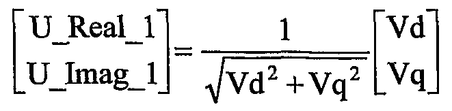
(equation 2) The polarity detector 325 generates a square wave in accordance with the voltage signals (Vd, Vq) output by the park transformation unit 321. This operation is defined as below: If Vd > =0 then Sq Real = 1 Else Sq_ReaI = 0 If Vq> =0 then Sqjmag = 1 Else Sqjmag = 0. (equation 3) Next, the phase transformation unit 326 multiples U_lmag_1 and U ReaM by un-filtered d-q voltage signals, Sq Real and Sqjmag (output by the polarity detector 325), to form the modulated product signals, sqc and sqs. By multiplying the unity voltage signals (U ReaM , UJmag_1 ) with the square wave references (Sq Real, Sqjmag), the phase transformation unit 326 produces phase shifting signals (sqs, sqc) of the two signals. The equation for this operation is: sqs - Sqjmag Sq teal UJtealJ sqc Sqjteal Sqjmag UJmagJ (equation 4) These products contain DC and AC components. The DC components correspond to the phase shift of the filtered references, and the AC components represent the harmonics contents in the power line 50. [0021] The low pass filters 327, 328 receive the outputs of the phase transformation unit 326, sqc and sqs, respectively. The low pass filters 327, 328 filter out the DC component of the phase shifting signals (sqs, sqc), outputting signals cos α and sin α, respectively. The DC components represent the phase shift of the voltage references (U ReaM , U lmag_1 ) with respect to the transformed voltages (Vd, Vq). The phase estimation unit 329 shifts the voltage references (U_Real_1 , U Jmag D to generate the reference signals (Sine, Cosine): ' Sine 1 cos α sin α UJtealJ CosineJ sin α - cos α UJmag 1 (equation 5) The reference signals (Sine, Cosine) will be used in transforming the measured voltage and current into the synchronous frame as discussed below. As described above, the band pass filters 322, 323 extract the fundamental voltage components in the d-q axis. However, this filtering causes phase shifting to the function. The polarity detector 325, the phase transformation unit 326, and the low pass filters 327, 328 compute the phase shifting. Based on the estimated phase shift, the phase estimation unit 329 corrects the voltage references by adjusting its phase in accordance with equation 5.
[0022] The measured current is transformed into the synchronous frame with respect to the voltage references signals Sine, Cosine output by the DPPL 320. The reference signals are computed from the measured voltages as described above. In accordance with these reference signals (Sine, Cosine), the compensating current reference estimator 312 transforms the measured currents are transformed with the equation defined as below:
Id Sine osm . e iq Cosine Sine
Figure imgf000010_0001
10 1 1
(equat. 6) [0023] The transformed current signals (Id, Iq, 10) consist of DC and AC components. The DC component corresponds to the fundamental current component and the AC component corresponds to the current harmonics. The power factor displacement constitutes the reactive current in the q-axis, and it is corresponded to the imaginary current Iq. Table 1 below shows the variations of transformed current component combinations that are used to estimate the compensating current reference.
Figure imgf000011_0001
[0024] In accordance with Table 1 , the transformed current constituents represent the power quality of three-phase power system 10. Thus, the compensating current reference estimator 31 2 uses Id, Iq, and I0 (the table defines the combinations in the above equations to improve the power quality) to calculate compensating values, led, lcq, and IcO in the d-q axis. The domain transformation unit 314 inversely transforms the compensating current (led, lcq, IcO) in dq-axis into abc domain (lea, lcb, Ice) and the inverter switching control unit 316 compares the resulting values to a triangle waveform to generate the switching control signals to the inverter. The following is the equation of the inverse transformation: led Sine lcq C Si.ne IcO
Figure imgf000012_0001
(equation 7). [0025] According to the present invention, the active filter 300 uses the characteristics of the transformed current to extract the power quality information and to inject a compensating current into the system 10. The controller 310 further receives a measure of the compensating current from the compensating current measuring unit 600 to adjust the switching control signals output to the inverter 340. [0026] FIG. 5 shows the simulated load with current harmonics and phase shifting. In FIG. 5, waveform (a) illustrates the source voltage (for one phase), waveform (b) illustrates the simulated effects of power conditions on the system, and waveform (c) illustrates the result of compensation. As seen from a comparison of waveforms (b) and (c), the active filter 300 injects a compensating current into the system to suppress the current harmonics. FIGs. 6A-6C illustrate the effect of the active filter 300 on multi-phase power conditions, where waveforms (1 )(a), (1 )(b), and (1 )(c) in FIG. 6A illustrate the effects of power conditions on three-phases of the load current (uncompensated); waveforms (2)(a), (2)(b), and (2)(c) in FIG. 6B illustrates three-phase input currents with active filter compensation; and waveforms (3)(a), (3)(b), and (3)(c) in FIG. 6C illustrates three-phase input voltage. As seen from a comparison of waveforms (2)(a), (2)(b), and (2)(c) with waveforms (1 )(a), (1 )(b), and (1 )(c), the active filter 300 in accordance with the principles of the present invention achieves harmonic, power factor, and phase compensation to improve total power quality in the AC system 10. This compensation is applicable to both constant and variable frequency environments.

Claims

We Claim: 1. An active filter (300) for generating multi-phase compensating current in an AC power supply system (10) that supplies a load (200), said filter comprising: a compensating current output device (340) outputting multi-phase compensating current to an AC power line (50); and a controller (310) for controlling said compensating current output such that the multi-phase compensating current compensates for current harmonics and power factor on said AC power line (50), said controller (310) estimating current harmonics and power factor compensating values as a function of multi-phase power measurement.
2. The active filter (300) according to claim 1 , wherein said multi-phase compensating current further compensates for phase imbalance of multi-phase voltage and multi-phase current of said power supply system (10) and said controller (310) estimates phase imbalance compensating values as a function of multi-phase supply voltage and multi-phase supply current measurements.
3. The active filter (300) according to claim 1 , wherein said controller (310) comprises: a digital phase lock loop unit (320) that computes voltage reference signals in a quadratic domain.
4. The active filter (300) according to claim 3, wherein said controller (310) further comprises: a compensating current reference estimator (312) that estimates compensating current reference values based on voltage reference signals computed by said digital phase lock loop unit (320), said compensating current reference values being in the quadratic domain; and a domain transformer (314) for transforming said compensating current reference values from said quadratic domain to a multi-phase current domain by using a look-up table.
5. The active filter (300) according to claim 3, wherein said digital phase lock loop unit (320) calculates reference voltage values by: transforming multi-phase voltage measurement values into a quadratic (d-q) reference frame signals; filtering the quadratic (d-q) reference frame signals to extract fundamental d-q voltage signals; and processing the fundamental d-q voltage signals to generate said reference voltage values.
6. The active filter (300) according to claim 4, wherein said compensating current reference values represent a plurality of power conditions, including current harmonics, power factor, and multi-phase current balance.
7. The active filter (300) according to claim 1 , wherein said power system (10) is a variable frequency power system of an aircraft.
8. A controller (310) of an active filter (300) that generates multi-phase compensating current in an AC power supply system (10) that supplies a load (200), said controller (310) performing the operations of: receiving multi-phase power measurements; calculating multi-phase compensating current based on said multiphase power measurements; and outputting control signals based on the calculated multi-phase compensating current to control a compensating current output device to compensate for current harmonics and power factor on an AC power line.
9. The controller (310) according to claim 8, wherein said multiphase compensating current further compensates for phase imbalance of multi-phase voltage and multi-phase current of said power supply system (10) and said controller (310) estimates phase imbalance compensating values as a function of multi-phase supply voltage and multi-phase supply current measurements.
10. The controller (310) according to claim 8, comprising: a digital phase lock loop unit (320) that computes voltage reference signals in a quadratic domain.
1 1 . The controller (310) according to claim 10, further comprising: a compensating current reference estimator (312) that estimates compensating current reference values based on voltage reference signals computed by said digital phase lock loop unit (320), said compensating current reference values being in the quadratic domain; and a domain transformer (314) for transforming said compensating current reference values from said quadratic domain to a multi-phase current domain by using a look-up table.
12. The controller (310) according to claim 10, wherein said digital phase lock loop unit (320) calculates reference voltage values by: transforming multi-phase voltage measurement values into a quadratic (d-q) reference frame signals; filtering the quadratic (d-q) reference frame signals to extract fundamental d-q voltage signals; and processing the fundamental d-q voltage signals to generate said reference voltage values.
13. The controller (310) according to claim 1 1 , wherein said compensating current reference values represent a plurality of power conditions, including current harmonics, power factor, and multi-phase current balance.
14. The controller (310) according to claim 8, wherein said power system (10) is a variable frequency power system of an aircraft.
PCT/US2004/026184 2003-08-13 2004-08-12 Active filter for multi-phase ac power system WO2005029669A2 (en)

Priority Applications (1)

Application Number Priority Date Filing Date Title
EP04809557A EP1656723A2 (en) 2003-08-13 2004-08-12 Active filter for multi-phase ac power system

Applications Claiming Priority (2)

Application Number Priority Date Filing Date Title
US10/640,091 2003-08-13
US10/640,091 US6861897B1 (en) 2003-08-13 2003-08-13 Active filter for multi-phase AC power system

Publications (2)

Publication Number Publication Date
WO2005029669A2 true WO2005029669A2 (en) 2005-03-31
WO2005029669A3 WO2005029669A3 (en) 2005-06-02

Family

ID=34136017

Family Applications (1)

Application Number Title Priority Date Filing Date
PCT/US2004/026184 WO2005029669A2 (en) 2003-08-13 2004-08-12 Active filter for multi-phase ac power system

Country Status (3)

Country Link
US (1) US6861897B1 (en)
EP (1) EP1656723A2 (en)
WO (1) WO2005029669A2 (en)

Cited By (1)

* Cited by examiner, † Cited by third party
Publication number Priority date Publication date Assignee Title
EP2202863A1 (en) * 2008-12-29 2010-06-30 Siemens Aktiengesellschaft Multilevel convertor as reactive power compensator with active power balancing

Families Citing this family (50)

* Cited by examiner, † Cited by third party
Publication number Priority date Publication date Assignee Title
US6950321B2 (en) * 2003-09-24 2005-09-27 General Motors Corporation Active damping control for L-C output filters in three phase four-leg inverters
WO2005043742A2 (en) * 2003-10-30 2005-05-12 The Regents Of The University Of California Universal three phase controllers for power converters
US7439753B2 (en) * 2005-11-23 2008-10-21 Zippy Technology Corp. Inverter test device and a method thereof
US20080016462A1 (en) * 2006-03-01 2008-01-17 Wyler Eran S Methods and apparatus for enabling use of web content on various types of devices
GB0710057D0 (en) * 2007-05-25 2007-07-04 Splashpower Power system
TWI356565B (en) * 2007-07-18 2012-01-11 Ablerex Electronics Co Ltd Modularized active power
FR2932590B1 (en) * 2008-06-17 2010-05-21 Mpe Technology MULTI-FUNCTIONAL AND CONTACTLESS ELECTRONIC LABEL FOR GOODS
US20100095024A1 (en) * 2008-09-25 2010-04-15 Infogin Ltd. Mobile sites detection and handling
US8193756B2 (en) * 2008-10-03 2012-06-05 Johnson Controls Technology Company Variable speed drive for permanent magnet motor
AU2009344066B2 (en) * 2009-04-09 2015-08-06 Abb Schweiz Ag An arrangement for exchanging power
DE102009023626A1 (en) 2009-05-27 2010-12-02 Siemens Aktiengesellschaft Device for compensation of harmonics
CN102804580B (en) * 2009-06-18 2015-08-05 Abb技术有限公司 For exchanging the equipment of power
US20110264299A1 (en) * 2010-04-27 2011-10-27 Siemens Industry, Inc. Method and system for managing power quality and efficiency
PL2398124T3 (en) * 2010-06-18 2018-10-31 General Electric Technology Gmbh Method to minimize input current harmonics of power systems such as ESP power systems
US20120016530A1 (en) * 2010-09-28 2012-01-19 George Albert Mazzoli Method and system for managing power quality and efficiency
DE102010051767A1 (en) * 2010-10-04 2012-04-05 Liebherr-Elektronik Gmbh Modules for an active line filter and active line filter
TWI403871B (en) 2010-10-25 2013-08-01 Ind Tech Res Inst Feedback switching device and method for servo motor driving
CN102565518A (en) * 2010-12-16 2012-07-11 鸿富锦精密工业(深圳)有限公司 Current balance test system
EP2725696A4 (en) * 2011-06-24 2015-05-06 Hitachi Ltd Power conversion device and device for controlling same
FR2983651B1 (en) * 2011-12-06 2014-01-03 Converteam Tech Ltd REACTIVE ENERGY COMPENSATOR AND METHOD FOR REDUCING THE ASSOCIATED PAPILLOTE PHENOMENON.
ES2900730T3 (en) * 2011-12-15 2022-03-18 Siemens Energy Global Gmbh & Co Kg Converter in triangular configuration
US10693294B2 (en) * 2012-09-26 2020-06-23 Stem, Inc. System for optimizing the charging of electric vehicles using networked distributed energy storage systems
US11289940B2 (en) 2013-06-14 2022-03-29 Abb Schweiz Ag Systems and methods for multi-use multi-mode ups
CN105164890A (en) * 2013-06-25 2015-12-16 惠普发展公司,有限责任合伙企业 Uninterruptible power supply with inverter, charger, and active filter
GB2519590A (en) * 2013-10-28 2015-04-29 Mohamad Hussein Taha Single phase parallel active filter for aircraft applications
CN103560516B (en) * 2013-11-19 2015-09-09 中南大学 A kind of Parallel Hybrid Active Power Filter and control method thereof
CN103997040B (en) * 2014-05-09 2016-10-19 安徽振兴科技股份有限公司 Improve active electric filter device harmonic wave control and the method for reactive-load compensation effect
DK3112029T3 (en) 2015-06-29 2021-11-22 General Electric Technology Gmbh IMPULSE IGNITION PATTERN FOR A TRANSFORMER IN AN ELECTROFILTER AND ELECTROFILTER
KR20170089354A (en) * 2016-01-26 2017-08-03 엘에스산전 주식회사 Controlling apparatus in static var compensator system and controlling method thereof
US10622813B2 (en) 2016-08-04 2020-04-14 Rolls-Royce North American Technologies Inc. Load alignment assistance during startup of synchronous grid
US10224854B2 (en) * 2016-08-04 2019-03-05 Rolls-Royce North American Technologies Inc. Active damping of synchronous grid oscillations using partial power converter
JP6756975B2 (en) * 2016-09-14 2020-09-16 富士電機株式会社 Power converter controller
US10170913B2 (en) 2016-11-29 2019-01-01 Mitsubishi Electric Power Products, Inc. Static synchronous compensator device and related method of phase balancing a three-phase power system
CN106786634A (en) * 2017-04-01 2017-05-31 北京智源新能电气科技有限公司 A kind of static reacance generator and its multiple target capacity control method for coordinating
US10170976B2 (en) 2017-04-26 2019-01-01 Delta Electronics (Thailand) Public Company, Limited Phase compensation method for power factor correction circuit
TWI635380B (en) * 2017-04-26 2018-09-11 泰達國際控股有限公司 Phase compensation method for power factor correction circuit
WO2018199333A1 (en) * 2017-04-28 2018-11-01 ダイキン工業株式会社 Power factor control system, phase modifying device, and active filter device
SG11201912353SA (en) * 2017-07-18 2020-01-30 Daikin Ind Ltd Active filter system and air conditioning device
US20190140569A1 (en) * 2017-11-09 2019-05-09 General Electric Company DFIG Converter Overmodulation
US20200003809A1 (en) * 2018-06-27 2020-01-02 Schneider Electric USA, Inc. Neutral connection detection method for 3/4 -wire active filters
AT521551A1 (en) * 2018-07-23 2020-02-15 Ait Austrian Inst Tech Gmbh Device for stabilizing and filtering interference in a multi-phase AC network
CN111656665B (en) * 2018-11-21 2023-04-07 东芝三菱电机产业系统株式会社 Power conversion device
CN110098616B (en) * 2019-05-14 2022-11-22 安徽亚辉电气自动化有限公司 Active power filter with load identification and classification calculation
US11736056B2 (en) * 2019-05-30 2023-08-22 General Electric Company System and method for controlling harmonics in a renewable energy power system
CN110176770B (en) * 2019-06-10 2022-12-27 上海电力学院 Control method of MMC type active power filter during power grid voltage unbalance
CN110581700B (en) * 2019-08-30 2021-01-29 浙江大学 Ultra-wideband second-order polyphase filter adopting inductance to compensate high-frequency gain
KR102525603B1 (en) * 2020-08-04 2023-04-27 성균관대학교산학협력단 Method for controlling fault using switching technique of three phase four wire interlinking converter
CN115036946A (en) * 2022-06-27 2022-09-09 云南电网有限责任公司电力科学研究院 Low-voltage station regional phase output power regulating system, regulating method and storage medium
ES2958907A1 (en) * 2022-07-19 2024-02-16 Gonotron Iberica S L Method of correction and balancing of electrical supply currents and adaptive active microfilter that implements said correction method
JP2024045981A (en) * 2022-09-22 2024-04-03 東芝キヤリア株式会社 Harmonic suppression device

Citations (4)

* Cited by examiner, † Cited by third party
Publication number Priority date Publication date Assignee Title
US5047909A (en) * 1987-09-28 1991-09-10 Kabushiki Kaisha Toshiba Power conversion apparatus with harmonic filtration
US5309353A (en) * 1992-10-02 1994-05-03 Westinghouse Electric Corp. Multiple reference frame controller for active filters and power line conditioners
US5731965A (en) * 1996-06-21 1998-03-24 Wisconsin Alumni Research Foundation Power line harmonic reduction by hybrid parallel active/passive filter system with square wave inverter and DC bus control
US20020039299A1 (en) * 2000-03-13 2002-04-04 Nissin Electric Co., Ltd. Isolated operation prevention device for distributed power supply and interharmonic detection method

Family Cites Families (16)

* Cited by examiner, † Cited by third party
Publication number Priority date Publication date Assignee Title
US4439823A (en) * 1982-01-11 1984-03-27 Westinghouse Electric Corp. Converting multiphase power from one frequency to another using current waveforms
US4600872A (en) * 1982-07-06 1986-07-15 Shepard Jr Francis H Apparatus for variable speed drive of an induction motor from a fixed frequency AC source
US4625160A (en) * 1984-12-17 1986-11-25 Sundstrand Corporation Variable speed constant frequency generating system
US4949021A (en) * 1988-11-14 1990-08-14 Sunstrand Corporation Variable speed constant frequency start system with selectable input power limiting
US4967097A (en) * 1989-03-08 1990-10-30 Mehl Bryon R Hybrid power system
US5068590A (en) * 1989-12-20 1991-11-26 Sundstrand Corporation Brushless generator having AC excitation in generating and starting modes
JPH05308799A (en) * 1992-04-28 1993-11-19 Shinko Electric Co Ltd Constant frequency power supply equipment
US5309081A (en) * 1992-08-18 1994-05-03 Sundstrand Corporation Power conversion system with dual permanent magnet generator having prime mover start capability
US5495163A (en) * 1993-05-12 1996-02-27 Sundstrand Corporation Control for a brushless generator operable in generating and starting modes
FR2716045B1 (en) * 1994-02-04 1996-03-15 Schlumberger Ind Sa Active filter.
US5668457A (en) * 1995-06-30 1997-09-16 Martin Marietta Corporation Variable-frequency AC induction motor controller
KR970063234A (en) * 1996-02-27 1997-09-12 김광호 1 How to check other channels during recording in TVCR with tuner
US6075350A (en) * 1998-04-24 2000-06-13 Lockheed Martin Energy Research Corporation Power line conditioner using cascade multilevel inverters for voltage regulation, reactive power correction, and harmonic filtering
DE19844050A1 (en) * 1998-09-25 2000-03-30 Abb Daimler Benz Transp Open and closed loop control method for electrical drive involving induction motor with voltage measured at output of sine wave filter in which complex vector is assigned in rotating reference system
US6195726B1 (en) * 1999-03-24 2001-02-27 Hewlett-Packard Company Method and apparatus for performing patterned read and write operations
US6545887B2 (en) * 1999-08-06 2003-04-08 The Regents Of The University Of California Unified constant-frequency integration control of three-phase power factor corrected rectifiers, active power filters and grid-connected inverters

Patent Citations (4)

* Cited by examiner, † Cited by third party
Publication number Priority date Publication date Assignee Title
US5047909A (en) * 1987-09-28 1991-09-10 Kabushiki Kaisha Toshiba Power conversion apparatus with harmonic filtration
US5309353A (en) * 1992-10-02 1994-05-03 Westinghouse Electric Corp. Multiple reference frame controller for active filters and power line conditioners
US5731965A (en) * 1996-06-21 1998-03-24 Wisconsin Alumni Research Foundation Power line harmonic reduction by hybrid parallel active/passive filter system with square wave inverter and DC bus control
US20020039299A1 (en) * 2000-03-13 2002-04-04 Nissin Electric Co., Ltd. Isolated operation prevention device for distributed power supply and interharmonic detection method

Cited By (3)

* Cited by examiner, † Cited by third party
Publication number Priority date Publication date Assignee Title
EP2202863A1 (en) * 2008-12-29 2010-06-30 Siemens Aktiengesellschaft Multilevel convertor as reactive power compensator with active power balancing
WO2010076079A1 (en) * 2008-12-29 2010-07-08 Siemens Aktiengesellschaft Multilevel converter as reactive power compensator having active power symmetrization
US8653799B2 (en) 2008-12-29 2014-02-18 Siemens Aktiengesellschaft Multilevel converter as reactive power compensator having active

Also Published As

Publication number Publication date
US20050035815A1 (en) 2005-02-17
WO2005029669A3 (en) 2005-06-02
US6861897B1 (en) 2005-03-01
EP1656723A2 (en) 2006-05-17

Similar Documents

Publication Publication Date Title
US6861897B1 (en) Active filter for multi-phase AC power system
Park et al. A novel method utilizing trapezoidal voltage to compensate for inverter nonlinearity
Forghani et al. Online wavelet transform-based control strategy for UPQC control system
Mishra et al. A novel method of load compensation under unbalanced and distorted voltages
EP1833153B1 (en) Electric engine start system with active rectifier
Basic Input current interharmonics of variable-speed drives due to motor current imbalance
Salmeron et al. A control strategy for hybrid power filter to compensate four-wires three-phase systems
US20140043014A1 (en) Phase-locked loop
US11936310B2 (en) Control method and device for three-phase AC system
US20120170333A1 (en) Semiconductor Power Conversion Apparatus
EP3104516A1 (en) Method and system for dead time compensation in a pwm controlled inverter
Zhang et al. Symmetric-component decoupled control of grid-connected inverters for voltage unbalance correction and harmonic compensation
Wamane et al. A comparative study on compensating current generation algorithms for shunt active filter under non-linear load conditions
Jabbarnejad et al. Combined control of grid connected converters based on a flexible switching table for fast dynamic and reduced harmonics
JP2007087154A (en) Controller for semiconductor switch
Hu et al. Predictive current control of grid-connected voltage source converters during network unbalance
Jabbarnejad et al. Power quality improvement using virtual flux combined control of grid connected converters under balanced and unbalanced grid operation
JP3822910B2 (en) Reduction of power line harmonics by hybrid parallel active / passive filter system with square wave inverter and DC bus control
KR100706181B1 (en) Single-Phase Active Power Filter Using Rotating Reference Frame
JP4523950B2 (en) Reactive power compensation device, reactive power compensation system, and reactive power compensation method
JP5850709B2 (en) Single operation detection device for grid-connected inverter device
EP3472906B1 (en) Identification method for identifying a resonance of a power grid, and grid-connected unit
US11777322B2 (en) Islanding detection mothod for inverter and apparatus
Hasan et al. Comparative study on combined series active and shunt passive power filter using two different control methods
Miskovic et al. Robust sensorless control of grid connected converters with LCL line filters using frequency adaptive observers as AC voltage estimators

Legal Events

Date Code Title Description
AK Designated states

Kind code of ref document: A2

Designated state(s): AE AG AL AM AT AU AZ BA BB BG BW BY BZ CA CH CN CO CR CU CZ DK DM DZ EC EE EG ES FI GB GD GE GM HR HU ID IL IN IS JP KE KG KP KZ LC LK LR LS LT LU LV MA MD MK MN MW MX MZ NA NI NO NZ PG PH PL PT RO RU SC SD SE SG SK SY TJ TM TN TR TT TZ UA UG US UZ VN YU ZA ZM

AL Designated countries for regional patents

Kind code of ref document: A2

Designated state(s): BW GH GM KE LS MW MZ NA SD SZ TZ UG ZM ZW AM AZ BY KG MD RU TJ TM AT BE BG CH CY DE DK EE ES FI FR GB GR HU IE IT MC NL PL PT RO SE SI SK TR BF CF CG CI CM GA GN GQ GW ML MR SN TD TG

121 Ep: the epo has been informed by wipo that ep was designated in this application
WWE Wipo information: entry into national phase

Ref document number: 2004809557

Country of ref document: EP

WWP Wipo information: published in national office

Ref document number: 2004809557

Country of ref document: EP