US8634119B2 - System for holography - Google Patents

System for holography Download PDF

Info

Publication number
US8634119B2
US8634119B2 US13/041,407 US201113041407A US8634119B2 US 8634119 B2 US8634119 B2 US 8634119B2 US 201113041407 A US201113041407 A US 201113041407A US 8634119 B2 US8634119 B2 US 8634119B2
Authority
US
United States
Prior art keywords
hologram
holographic
beams
recording material
hoe
Prior art date
Legal status (The legal status is an assumption and is not a legal conclusion. Google has not performed a legal analysis and makes no representation as to the accuracy of the status listed.)
Active, expires
Application number
US13/041,407
Other versions
US20120008482A1 (en
Inventor
Arkady Bablumyan
Pierre-Alexandre Jean Blanche
Nasser N. Peyghambarian
Current Assignee (The listed assignees may be inaccurate. Google has not performed a legal analysis and makes no representation or warranty as to the accuracy of the list.)
TIPD LLC
Original Assignee
TIPD LLC
Priority date (The priority date is an assumption and is not a legal conclusion. Google has not performed a legal analysis and makes no representation as to the accuracy of the date listed.)
Filing date
Publication date
Application filed by TIPD LLC filed Critical TIPD LLC
Priority to US13/041,407 priority Critical patent/US8634119B2/en
Assigned to TIPD, LLC reassignment TIPD, LLC ASSIGNMENT OF ASSIGNORS INTEREST (SEE DOCUMENT FOR DETAILS). Assignors: BABLUMYAN, ARKADY, BLANCHE, PIERRE-ALEXANDRE JEAN, PEYGHAMBARIAN, NASSER N.
Publication of US20120008482A1 publication Critical patent/US20120008482A1/en
Application granted granted Critical
Publication of US8634119B2 publication Critical patent/US8634119B2/en
Assigned to GOVERNMENT OF THE UNITED STATES AS REPRESENTED BY THE SECRETARY OF THE AIR FORCE reassignment GOVERNMENT OF THE UNITED STATES AS REPRESENTED BY THE SECRETARY OF THE AIR FORCE CONFIRMATORY LICENSE (SEE DOCUMENT FOR DETAILS). Assignors: TIPD, LLC
Active legal-status Critical Current
Adjusted expiration legal-status Critical

Links

Images

Classifications

    • GPHYSICS
    • G11INFORMATION STORAGE
    • G11BINFORMATION STORAGE BASED ON RELATIVE MOVEMENT BETWEEN RECORD CARRIER AND TRANSDUCER
    • G11B7/00Recording or reproducing by optical means, e.g. recording using a thermal beam of optical radiation by modifying optical properties or the physical structure, reproducing using an optical beam at lower power by sensing optical properties; Record carriers therefor
    • G11B7/004Recording, reproducing or erasing methods; Read, write or erase circuits therefor
    • G11B7/0065Recording, reproducing or erasing by using optical interference patterns, e.g. holograms
    • GPHYSICS
    • G03PHOTOGRAPHY; CINEMATOGRAPHY; ANALOGOUS TECHNIQUES USING WAVES OTHER THAN OPTICAL WAVES; ELECTROGRAPHY; HOLOGRAPHY
    • G03HHOLOGRAPHIC PROCESSES OR APPARATUS
    • G03H1/00Holographic processes or apparatus using light, infrared or ultraviolet waves for obtaining holograms or for obtaining an image from them; Details peculiar thereto
    • G03H1/02Details of features involved during the holographic process; Replication of holograms without interference recording
    • GPHYSICS
    • G03PHOTOGRAPHY; CINEMATOGRAPHY; ANALOGOUS TECHNIQUES USING WAVES OTHER THAN OPTICAL WAVES; ELECTROGRAPHY; HOLOGRAPHY
    • G03HHOLOGRAPHIC PROCESSES OR APPARATUS
    • G03H1/00Holographic processes or apparatus using light, infrared or ultraviolet waves for obtaining holograms or for obtaining an image from them; Details peculiar thereto
    • G03H1/0005Adaptation of holography to specific applications
    • G03H1/0011Adaptation of holography to specific applications for security or authentication
    • GPHYSICS
    • G03PHOTOGRAPHY; CINEMATOGRAPHY; ANALOGOUS TECHNIQUES USING WAVES OTHER THAN OPTICAL WAVES; ELECTROGRAPHY; HOLOGRAPHY
    • G03HHOLOGRAPHIC PROCESSES OR APPARATUS
    • G03H1/00Holographic processes or apparatus using light, infrared or ultraviolet waves for obtaining holograms or for obtaining an image from them; Details peculiar thereto
    • G03H1/04Processes or apparatus for producing holograms
    • GPHYSICS
    • G03PHOTOGRAPHY; CINEMATOGRAPHY; ANALOGOUS TECHNIQUES USING WAVES OTHER THAN OPTICAL WAVES; ELECTROGRAPHY; HOLOGRAPHY
    • G03HHOLOGRAPHIC PROCESSES OR APPARATUS
    • G03H1/00Holographic processes or apparatus using light, infrared or ultraviolet waves for obtaining holograms or for obtaining an image from them; Details peculiar thereto
    • G03H1/26Processes or apparatus specially adapted to produce multiple sub- holograms or to obtain images from them, e.g. multicolour technique
    • GPHYSICS
    • G03PHOTOGRAPHY; CINEMATOGRAPHY; ANALOGOUS TECHNIQUES USING WAVES OTHER THAN OPTICAL WAVES; ELECTROGRAPHY; HOLOGRAPHY
    • G03HHOLOGRAPHIC PROCESSES OR APPARATUS
    • G03H1/00Holographic processes or apparatus using light, infrared or ultraviolet waves for obtaining holograms or for obtaining an image from them; Details peculiar thereto
    • G03H1/02Details of features involved during the holographic process; Replication of holograms without interference recording
    • G03H2001/026Recording materials or recording processes
    • G03H2001/0264Organic recording material
    • GPHYSICS
    • G03PHOTOGRAPHY; CINEMATOGRAPHY; ANALOGOUS TECHNIQUES USING WAVES OTHER THAN OPTICAL WAVES; ELECTROGRAPHY; HOLOGRAPHY
    • G03HHOLOGRAPHIC PROCESSES OR APPARATUS
    • G03H1/00Holographic processes or apparatus using light, infrared or ultraviolet waves for obtaining holograms or for obtaining an image from them; Details peculiar thereto
    • G03H1/04Processes or apparatus for producing holograms
    • G03H1/0476Holographic printer
    • G03H2001/0482Interference based printer
    • GPHYSICS
    • G03PHOTOGRAPHY; CINEMATOGRAPHY; ANALOGOUS TECHNIQUES USING WAVES OTHER THAN OPTICAL WAVES; ELECTROGRAPHY; HOLOGRAPHY
    • G03HHOLOGRAPHIC PROCESSES OR APPARATUS
    • G03H1/00Holographic processes or apparatus using light, infrared or ultraviolet waves for obtaining holograms or for obtaining an image from them; Details peculiar thereto
    • G03H1/22Processes or apparatus for obtaining an optical image from holograms
    • G03H1/2249Holobject properties
    • G03H2001/2263Multicoloured holobject
    • G03H2001/2271RGB holobject
    • GPHYSICS
    • G03PHOTOGRAPHY; CINEMATOGRAPHY; ANALOGOUS TECHNIQUES USING WAVES OTHER THAN OPTICAL WAVES; ELECTROGRAPHY; HOLOGRAPHY
    • G03HHOLOGRAPHIC PROCESSES OR APPARATUS
    • G03H1/00Holographic processes or apparatus using light, infrared or ultraviolet waves for obtaining holograms or for obtaining an image from them; Details peculiar thereto
    • G03H1/26Processes or apparatus specially adapted to produce multiple sub- holograms or to obtain images from them, e.g. multicolour technique
    • G03H1/30Processes or apparatus specially adapted to produce multiple sub- holograms or to obtain images from them, e.g. multicolour technique discrete holograms only
    • G03H2001/303Interleaved sub-holograms, e.g. three RGB sub-holograms having interleaved pixels for reconstructing coloured holobject
    • GPHYSICS
    • G03PHOTOGRAPHY; CINEMATOGRAPHY; ANALOGOUS TECHNIQUES USING WAVES OTHER THAN OPTICAL WAVES; ELECTROGRAPHY; HOLOGRAPHY
    • G03HHOLOGRAPHIC PROCESSES OR APPARATUS
    • G03H2210/00Object characteristics
    • G03H2210/202D object
    • G03H2210/222D SLM object wherein the object beam is formed of the light modulated by the SLM
    • GPHYSICS
    • G03PHOTOGRAPHY; CINEMATOGRAPHY; ANALOGOUS TECHNIQUES USING WAVES OTHER THAN OPTICAL WAVES; ELECTROGRAPHY; HOLOGRAPHY
    • G03HHOLOGRAPHIC PROCESSES OR APPARATUS
    • G03H2223/00Optical components
    • G03H2223/19Microoptic array, e.g. lens array
    • GPHYSICS
    • G03PHOTOGRAPHY; CINEMATOGRAPHY; ANALOGOUS TECHNIQUES USING WAVES OTHER THAN OPTICAL WAVES; ELECTROGRAPHY; HOLOGRAPHY
    • G03HHOLOGRAPHIC PROCESSES OR APPARATUS
    • G03H2223/00Optical components
    • G03H2223/23Diffractive element
    • GPHYSICS
    • G03PHOTOGRAPHY; CINEMATOGRAPHY; ANALOGOUS TECHNIQUES USING WAVES OTHER THAN OPTICAL WAVES; ELECTROGRAPHY; HOLOGRAPHY
    • G03HHOLOGRAPHIC PROCESSES OR APPARATUS
    • G03H2260/00Recording materials or recording processes
    • G03H2260/30Details of photosensitive recording material not otherwise provided for
    • G03H2260/35Rewritable material allowing several record and erase cycles
    • GPHYSICS
    • G03PHOTOGRAPHY; CINEMATOGRAPHY; ANALOGOUS TECHNIQUES USING WAVES OTHER THAN OPTICAL WAVES; ELECTROGRAPHY; HOLOGRAPHY
    • G03HHOLOGRAPHIC PROCESSES OR APPARATUS
    • G03H2260/00Recording materials or recording processes
    • G03H2260/50Reactivity or recording processes
    • G03H2260/54Photorefractive reactivity wherein light induces photo-generation, redistribution and trapping of charges then a modification of refractive index, e.g. photorefractive polymer

Definitions

  • This invention relates to recording holograms and, more particularly, to methods and techniques to improve the quality, recording speed, efficiency and color displaying of holograms. These methods may find particular applications with photorefractive polymers or other holographic recording materials for integral holographic 3D display and other applications.
  • Holography is a technique that allows the light scattered from an object to be recorded and later reconstructed so that the object appears as if the object is in the same position relative to the recording medium as it was when recorded.
  • holograms can be computer generated by calculating the modulation pattern that would have been formed if beams with certain characteristics (wave front, intensity) had crossed each other. The calculated pattern is next transferred to a medium to make the actual hologram. The image changes as the position and orientation of the viewing system change in exactly the same way is if the object were still present, thus making the recorded image (hologram) appears three-dimensional.
  • the technique of holography can also be used to optically store, retrieve, and process information (data storage); or to generate a particular wavefront (holographic optical element “HOE”).
  • An HOE is an optical lens or lenses that converts an incoming wavefront to another wavefront using the diffraction principle. While holography is commonly used to display static 3-D pictures and simple 3D images have been successfully rendered, the generation of arbitrary scenes by a holographic display is not yet possible.
  • Typical media include, photothermoplastics, photopolymers, photochromics, silver halide, plates or films, and photorefractive (PR) polymers and crystals.
  • FIG. 1 illustrates the so-called transmission geometry where the recording beams 12 and 10 are incident on the same side of the holographic storing medium 14 .
  • FIG. 2 recording beams 50 and 52 are incident from opposite sides of the holographic storing medium 54 . This is the reflection geometry.
  • the diffracted beam 62 emerges from the opposite side of the material 64 .
  • the diffracted beams 62 and 68 exit the media 64 at different angles and with different diffraction efficiency according to the hologram characteristics.
  • the diffracted beam 72 is diffracted to the same side of the material 74 .
  • the diffracted beams 72 and 78 exit the media 74 at different angles.
  • the diffracted intensity is strongly attenuated (Bragg regime hologram). This is referred to as color selectivity.
  • PR polymers are dynamic holographic recording materials.
  • an embodiment of a recording device 20 includes a layer of PR polymer material 22 sandwiched between a ground electrode 24 on an electrode support 26 and a high-voltage electrode 28 on an electrode support 30 .
  • a high-voltage power supply 32 applies a voltage between ground electrode 24 and high-voltage electrode 28 to provide a bias electric field 34 across the PR polymer.
  • a three-dimensional refractive index pattern—a phase hologram 40 replicates the non-uniform interference pattern 42 formed by the two incident coherent light fields 44 and 46 .
  • This effect is based on the build-up of an internal space-charge field E s 48 due to selective transport and trapping of the photo-generated charges 50 , and an electric field induced index change via the electro-optic effect.
  • This process in contrast to photochemical processes involved in photopolymer holograms—is fully reversible, as trapped charges can be de-trapped by uniform illumination.
  • the erasability of the PR gratings allows for refreshing/updating of the holograms.
  • the holograms are viewed with the help of a reading beam, as long as the initial writing (recording) beams are present.
  • the writing beams are turned off, the hologram written in the PR polymer decays at a rate determined by the material properties and ambient temperature.
  • the quality of the PR polymer and the written hologram can be evaluated with respect to three parameters: sensitivity, diffraction efficiency and persistence.
  • the sensitivity is usually defined as the first temporal derivative of the dynamic efficiency measurement at the origin divided by the writing beams power. However, it is sometime more convenient to use the notion of writing time. Writing time and sensitivity are related quantities. As shown in FIG. 7 , in continuous wave illumination, the writing time T w is simply how long the writing beams must illuminate the media to achieve the desired diffraction efficiency of the hologram.
  • the diffraction efficiency 82 is defined as the ratio between the intensity of the diffracted beam and the incident beam. In theory, PR polymers can achieve up to 100% diffraction efficiency.
  • the persistence is a measure of the rate of decay of the hologram.
  • Holographic 3D displays are one application of re-writable holograms.
  • Computer generated holographic 3D displays provide highly realistic images without the need for special eyewear, making them valuable tools for applications that require “situational awareness” such as medical, industrial, and military imaging.
  • Current commercially available holographic 3D displays employ material like photopolymers or silver halide emulsion that lack image-updating capability, resulting in their restricted use and high cost.
  • Dynamic updateable 3D holographic displays based on acousto-optic, liquid crystal display and MEMS based recording media have been demonstrated. Unfortunately, these devices do not have memory, and thus do not exhibit persistence of recorded images. The lack of persistence results in the requirement of update rates faster than 30 Hz to avoid image flicker.
  • Integral imaging is an auto stereoscopic technique that allows reproduction of 3D images with a flat (2D) display.
  • Auto stereoscopic means there is no need for the viewer to wear eyewear to see the 3D effect.
  • This technique is summarized in FIG. 8 where an array of lenses 92 is placed in front of the regular flat display 90 (static or dynamic) to redirect the light coming from individual pixels 98 so the viewer see different information at different angles.
  • Individual lenses 96 of the lens array cover a defined surface of the display 94 .
  • the vertical and horizontal resolution of this kind of 3D display is defined by the number of lenses per unit of surface.
  • the angular resolution is defined by the number of individual pixels covered by an individual lens 96 .
  • HPO horizontal parallax only
  • Holography can also be used for integral imaging (referred to as “integral holography”).
  • integrated holography what was a collection of individual pixels 94 is shrunk into a single holographic pixel (hogel) by a lens.
  • the function of the individual lenses 96 that collimate the beams is also recorded as a hologram into the material.
  • the advantage is that the resolution can be much higher than with a regular lens array and 2D display since the pixels and lens do not need any physical embodiment.
  • the resolution limitation now comes from the optical recording setup resolution that is usually orders of magnitude higher than regular lens array resolution.
  • FIG. 9 A typical integral holographic optical system using a grey-scale (single-color) transmission geometry is shown in FIG. 9 .
  • a laser 300 emits a coherent beam 310 that is split into a reference beam 320 and an object beam 330 by a beam splitter 340 .
  • the object beam is expanded by means of a telescope 350 and the beam's amplitude is structured by a device 360 that can be a transparent image, a mask, a spatial light modulator etc.
  • the object beam is then resized by a telescope 370 , directed by one or several mirrors 380 , and focused by a lens 390 to the holographic recording material 400 . That lens 390 is spherical in the case of full parallax and cylindrical in the case of horizontal parallax only.
  • the reference beam 320 is shaped by optics 410 to match the shape of the object beam at the holographic material location, and directed by a mirror 420 to the holographic recording material. After one hogel has been recorded, the material is moved to the next hogel location by a translation stage 430 .
  • Controlling electronics 500 ensures the synchronization between the laser 300 , the translation stage 430 and the device 360 that structures the object beam.
  • the device 360 that structures the object beam 330 is electronic; a memory 510 could be used to store the hogel data.
  • the material is positioned or otherwise shielded so that the powerful writing beam is not incident on a viewer's eyes for safety.
  • the material is processed to develop the hologram (if needed) and moved to the reading position 440 , where a reading source 450 emits a light beam 460 that is expanded by a telescope 470 and diffracted by the hologram 440 in a diffracted beam 480 toward the viewer's eyes.
  • the holographic recording device 400 when the hologram needs to be erased, the holographic recording device 400 is moved to the erasing location, where the erasing process occurs.
  • an erasing light source 600 emits a beam 610 that is expanded with a telescope 620 and illuminates the whole hologram area.
  • Some materials need a heating process for the hologram to be erased.
  • Some materials like photo thermo plastic need electrical charging and heating the material to erase the hologram. Once erased, the recording material is moved back to the recording position.
  • the present invention provides methods of recording holograms that reduce the writing time, increase the diffraction efficiency, improve the resolution, or restitute color. These techniques are well suited for use with an updateable 3D holographic display using integral holography and photorefractive polymer.
  • a system for recording a hologram includes a laser that produces a coherent beam and a holographic recording material.
  • the laser beam is split into an object beam and a reference beam.
  • the intensity of the object beam is spatially structured with information to write a hologram or part of a hologram in case of holographic stereogram.
  • a beam steering mechanism steers the encoded object beam and reference beam to interfere at the holographic recording material to record the hologram or sequence of holograms.
  • a holographic optical element diffracts one of the object or reference beams to reduce the angle between the grating vector and the external dielectric field and increase the diffraction efficiency of the PR polymer.
  • the HOE is configured to allow one of the object or reference beams to pass there through and to diffract the other beam to reduce the angle between the grating vector and the external electric field to increase the diffraction efficiency of the PR polymer.
  • a first lens array focuses the object beam on the recording material at multiple positions.
  • the object beam is spatially structured so that each position corresponds to the correct hogel data.
  • a second lens array splits the reference beam into multiple reference beams that are directed to the first lens array that collimates the multiple reference beams. If the beams overlap each other at the second lens array, the array is implemented as a HOE including an angularly selective grating to let the object beam pass unaffected while splitting and redirecting the reference beams.
  • the second lens array may be implemented as a HOE that also diffracts the reference beams to reduce the angle between the grating vector and the external dielectric field and increase the diffraction efficiency of the PR polymer.
  • the multiple object and multiple reference beams interfere at the multiple positions on the material to write multiple hogels simultaneously.
  • the lens arrays may also be configured for HPO or reflective geometry as well.
  • the first and second lens arrays may be translated along a single axis at an oblique angle to the x-axis to write multiple holograms over the entire surface of the recording material as a series of parallel rows. This is an effective scanning system using only one translation direction and a fixed sample.
  • a spatial light modulator having different zones is loaded with hogel data for different colors to spatially structure the object beam and form the modulated object beam.
  • a focusing lens redirects the different zones of the modulated object beam at correct angles of incidence for each color towards the recording material such that diffraction of multiple color reading beams through the recording material produces multiple object beams with different colors that superimpose at a common viewer position.
  • a first optical system separate the laser beam into reference and object beams having both orthogonal polarization components (horizontal and vertical or circular left and right polarizations).
  • a second optical system splits the object beam into first, second and third object beams. The first and second object beams have one polarization component and the third object beam has the orthogonal polarization component.
  • the first and second object beams are positioned to have a symmetrical angle of incidence so that the grating vector of a hologram formed by cross-talk is perpendicular to the external electric field applied to the material so that the diffraction efficiency is near zero.
  • the angles of incidence for all three object beams satisfy the Bragg equation so that when, for example, each hologram is read with a different color it displays a full color hologram in the direction of the audience.
  • a holographic element is positioned after the recording material to redirect the reading beam diffracted by the hologram approximately orthogonal to the recording material toward the viewer position to provide a more natural look at the display.
  • Positioning a holographic lens after the material changes the orientation of the cones of light diffracted by the hogels.
  • the lens may be designed so that rays of light entering the viewer pupil have the same angles inside the cone of light for each hogel and the correct part of the hogel is perceived rendering the correct image with the viewer located at a specified finite distance.
  • a first HOE splits and diffracts the reference beam into multiple reference beams
  • a second HOE collimates the multiple reference beams and focuses the object beam so that the multiple object and multiple reference beams interfere at multiple positions on the material to write multiple holograms simultaneous
  • a third HOE positioned after the recording material to redirect a reading beam transmitted through the recording beam approximately orthogonal to the recording material toward a viewer position to provide a more natural look at the display.
  • a mask/mirror is positioned between the laser and the holographic recording material.
  • the mask mirror comprises an aperture that defines the extent of a hogel and a mirror surface facing the recording material.
  • a translation stage moves the mask/mirror to synchronize the position of the aperture with the location of the steered object and reference and beams.
  • a read source is positioned on the opposite side of the recording material to direct the reading beam through the material where it reflects off the mirrored surface and is transmitted back through the hologram in the material where it is diffracted to produce the diffracted beam.
  • a filter may be positioned between the recording material and the viewer to absorb the object and reference beams that may pass through the material.
  • the object beam is used to simultaneously erase the structure of the previous hologram and write the current hologram.
  • the laser power is high enough to erase the previous hologram without leaving a ghost image and low enough to record the current hologram without causing a permanent set.
  • the object beam reduces the diffraction efficiency of the previous hologram to less than 20% when writing the current hologram.
  • the horizontal and vertical image planes need to be disassociated during the holographic recording.
  • the best resolution happens when the vertical image plane is at the holographic recording material position and the horizontal image plane is near the Fourier cylindrical lens position.
  • the object beam is shaped by a spherical lens and then collimated with a spherical mirror at an angle.
  • the natural astigmatism of the spherical mirror is used to disassociate the image plane so the horizontal image plane is near a Fourier cylindrical lens and the vertical image plane is near the holographic recording material.
  • the holographic recording material comprises a PR polymer
  • a pair of interleaved electrodes is deposited on one surface of the PR polymer. With such a pattern, the orientation of the electric field is parallel to the sample surface if the sample is thin compared to the space between the electrodes. If the plane of incidence (plane comprising both writing beams) has a component parallel to the field vectors, the grating vector will also have a component along the electric field and the photorefractive effect will occur.
  • FIG. 1 is a diagram of a transmission geometry for forming a hologram
  • FIG. 2 is a diagram of a reflection geometry for forming a hologram
  • FIG. 3 is a diagram of a transmission geometry for reading a hologram
  • FIG. 4 is a diagram of a reflection geometry for reading a hologram
  • FIG. 5 is a diagram a recording device using a photorefractive polymer material
  • FIG. 6 is a diagram illustrating the photorefractive effect
  • FIG. 7 is a diagram of the diffraction efficiency during a write and dark decay
  • FIG. 8 is a diagram illustrating an integral imaging technique for reproducing 3D images with a 2D display
  • FIG. 9 is a diagram of an integral holographic setup for writing, reading and erasing holograms
  • FIG. 10 is a diagram of a holographic optical element for improving diffraction efficiency in accordance with an embodiment of the invention.
  • FIGS. 11 , 12 and 13 are diagrams illustrating the use of holographic optical elements to multiplex the recording of the hologram in accordance with an embodiment of the invention
  • FIGS. 14 , 15 and 16 are diagrams for a single axis scanning system for full surface recording of a pixilated holographic display in accordance with an embodiment of the invention
  • FIGS. 17 and 18 are diagram of a multiplexed recording of a color hologram in accordance with an embodiment of the invention.
  • FIGS. 19 a and 19 b are diagrams of different embodiments of a symmetrical geometry to simultaneously record a multiplexed hologram in a photorefractive media is a diagram of a multiplexed recording of a color hologram in accordance with an embodiment of the invention
  • FIGS. 20 , 21 and 22 are diagrams illustrating the use of a holographic element for view plane compensation in accordance with an embodiment of the invention
  • FIG. 23 is a diagram of a retroflector for simultaneous writing and reading for a transmission geometry in accordance with an embodiment of the invention.
  • FIG. 24 is a diagram of simultaneous erasing and writing of a hogel in accordance with an embodiment of the invention.
  • FIGS. 25 and 26 are diagrams of a reflective off-axis telescope for resolution improvement in a horizontal parallax only (HPO) geometry in accordance with an embodiment of the invention
  • FIGS. 27 , 28 and 29 are diagrams of an interleaved electrode for external field application in photorefractive polymer material in accordance with an embodiment of the invention.
  • FIG. 30 is diagram of holographic system employing three HOEs to multiplex the recording of the hologram, improve the diffraction efficiency and provide for view plan compensation.
  • the present invention provides methods of recording holograms that reduce the writing time, improve the resolution, increase the efficiency, or restitute color. These techniques are well suited for use with an updateable 3D holographic display using integral holography. These techniques may be used individually or in combination.
  • the diffraction efficiency strongly depends on the angle between the grating vector and the external applied field direction.
  • the grating vector is perpendicular to the bisector of the object and reference beams inside the recording material.
  • the diffraction is minimum when this angle is 90° and maximum when this angle is 0°. This is due to the charge transport mechanism that is governed by drift.
  • PR polymer it is important to minimize this angle to optimize the diffraction efficiency.
  • transmission gratings this is achieved by using a non-symmetrical geometry where the sample is tilted according to the bisector formed by the object and reference beams.
  • this angle is limited to a certain value. This is the case for a 3D display where there is optics obstruction in the recording setup.
  • a holographic optical element redirects the beams near the sample to increase the incident angle without changing the holographic recording setup main optics.
  • a holographic optical element 102 e.g. a diffraction grating
  • a writing beam 106 is diffracted toward a PR material 100 while the other recording beam 104 passes through element 102 without being diffracted. This can be achieved by using a highly angular selective diffraction grating.
  • the grating vector 107 into the holographic recording material is redirected at a shallower angle considering the device external field vector 108 .
  • HOE 102 may be positioned so that only the diffracted writing beam 106 passes there through.
  • the writing beam may be either object beam or the reference beam.
  • a holographic optical element 112 may be used in combination with a lens array to multiplex the holographic recording in order to reduce the recording time.
  • the technique of integral imaging by holographic recording requires the whole display surface to be filled with holographic pixels. In the case of large surface and good resolution, a large number of pixels need to be recorded. Recording multiple pixels at once (spatial multiplexing) is a way to reduce the recording time.
  • FIG. 11 shows how a lens array (HOE or other) 112 that refracts (diffracts) a first writing beam 114 (e.g. the object beam) into multiple writing beams 116 incident on a sample 110 .
  • the writing beam or beams may be modulated with a single SLM that is spatially structured to coincide with the multiple writing beams or with multiple SLMs, one for each writing beam.
  • the second writing beam (the reference beam) must also be incident to the sample and overlap the first beam spots. If the second beam is uncorrected, it will pass through the lens array 112 and be focused outside the spots of the first beam.
  • a second lens array (refractive or HOE) 122 is introduced into the path of a second writing beam 120 (e.g. the reference beam) and refracts (diffracts) the beam into multiple reference beams 124 at the correct angle.
  • a second writing beam 120 e.g. the reference beam
  • refracts diffracts
  • the second beams 126 may be collimated when incident to the sample and the spot size at the sample location should match the spot size of the first beams 116 .
  • the lens arrays 112 and 122 should work as a telescope so the diameter of the beams 126 matches the diameter of the beams 116 at the sample location (see FIG. 13 ).
  • the lens array can be replaced by a HOE comprising an angular selective grating that only diffracts the beam coming at a specific angle. Beam 120 is oriented accordingly so it is diffracted and focused by the HOE while beam 114 passes through, unaffected (see FIG. 13 ).
  • the lens arrays are constituted of vertical cylindrical lenses. In case of full parallax, the lens arrays are constituted of spherical lenses.
  • This system can be used in conjunction with the HOE designed for efficiency improvement.
  • the holographic element that redirects the reference beam to improve diffraction (element 102 FIG. 10 ) and the one that focuses the reference beam (element 122 FIG. 13 ) can be combined into a single HOE that performs both those functions.
  • the object beam is horizontal for the sake of clarity instead of tilted as presented in FIG. 10 .
  • the benefit of this combination is more compact setup with less optical surfaces.
  • the horizontal displacement of the lens array 112 and the holographic element 122 is enough to cover the entire surface of the recording material 140 with hogels 150 as a series of parallel rows and record the full hologram.
  • the lens arrays 112 and 122 may be translated along a single axis at an oblique angle to the x-axis write the hogels 130 over the entire surface of a recording material 140 as a series of parallel rows 150 .
  • This is an effective scanning system using only one translation direction and a fixed sample; there is no need to move the sample as shown in FIG. 9 .
  • the only condition is that there is a group of spare pixels 156 on the side of the sample to cover the whole area of the sample.
  • Color transmission holograms can be made (among other techniques) by angular multiplexing several transmission holograms that will diffract specific color when replayed. Recording angles are selected so the Bragg grating equation is fulfilled when replayed with a different wavelength than the recording wavelength. The angle should also be such that the diffracted beams coming from the different holograms superimpose on each other so the viewer sees the different views as a single colored hologram.
  • a known technique for recording an angular multiplexed hologram in which only the chief ray is drawn for the sake of clarity is shown in FIG. 17 .
  • a laser light source 170 emits a coherent light beam 172 .
  • Beams splitters 190 separate the beam into one (or several) reference beam 174 and several object beams 176 , 178 and 180 .
  • Mirrors 192 reorient the different beams so they interfere at the holographic recording material location 182 .
  • the different object beams are modulated with separated devices (spatial light modulator) 184 , 186 , and 188 to encode the color information.
  • different portions of the spatial light modulator may be dedicated for different colors in accordance with the invention.
  • the lenslet array has been reduced to one single lens and a single SLM is used to write the 3 colors.
  • a laser light source 200 emits a coherent beam 202 that is split into a reference beam 206 and an object beam 208 .
  • the object beam is expanded by the means of a beam expander 210 (aka two lenses) to fit the spatial light modulator device 214 size.
  • the spatial light modulator is divided in three different zones 216 , 218 , and 220 corresponding to different holograms to be multiplexed.
  • the different zones are loaded with hogel data for the three different colors to spatially structure the object beam.
  • a focusing lens 224 e.g. a holographic optical element redirects the different portions of the object beam 226 , 228 , and 230 at the correct angles toward the holographic recording material 232 .
  • the diffracted angles are not identical to the writing angles on account of spectral dispersion. If the object beams incident on the recording material were parallel during recording, the diffracted object beams will diverge from each other during display and the colors will not superimpose at a common viewer position but instead will be seen at different viewer positions. To correct for this, the object beams must have a different angle predetermined by the Bragg law. Those angles referred to above as the “correct angles” can be imposed to the object beam by using the focusing lens 224 that redirects the spatially separated parallel beams. That spatial separation (structure) can be achieved by using different zones of one single SLM.
  • Element 224 from FIG. 18 can be the same as element 112 from FIG. 13 .
  • color and multiplexing are combined together to write several hogels at once that will reproduce color.
  • Full color holograms can be generated by integral holography by recording three holograms one for each fundamental color (red green and blue).
  • One approach is to use three separate writing lasers, one for each color.
  • different techniques can be used.
  • angular multiplexing can be used with a single laser source to successively record the three holograms.
  • the successive hologram erases (at least partially) the preceding one, leading to a decrease in diffraction efficiency.
  • the recording beams that belong to different holograms should not interfere with each other.
  • the beam is separated into reference and object beams having both polarization components (horizontal and vertical or circular left and right polarizations).
  • the object beam is split and polarized to produce three object beams that are incident at different angles to the media.
  • two of the object beams have orthogonal polarization.
  • the third beam which must have one of the two polarizations, is positioned at an angle of incidence to take advantage of the fact that photorefractive polymers do not record holograms if the vector is orthogonal to the external electric field.
  • Each object beam is encoded with hogel data for one of the primary colors. This can be done with a dedicated SLM for each object beam or with a single SLM that is spatially structured to modulate all of the object beams simultaneously.
  • FIG. 19 a An embodiment of a recording geometry with angular and polarization diversity is presented in FIG. 19 a , a single laser source 1500 emits a coherent light beam 1502 that is split into 4 recording beams 1504 , 1506 , 1508 and 1510 with the appropriate optical elements (e.g. polarizing beam splitters and wave plates). Those beams interfere into the photorefractive polymer material 1512 that has electrical electrodes 1514 and 1616 on opposing surfaces (see FIG. 5 ). For example, an optical system splits beam 1502 into reference beam 1510 containing both orthogonal polarizations and the object beam and a second optical system splits the object beam into three different object beams 1504 , 1506 and 1508 .
  • the appropriate optical elements e.g. polarizing beam splitters and wave plates.
  • Those beams interfere into the photorefractive polymer material 1512 that has electrical electrodes 1514 and 1616 on opposing surfaces (see FIG. 5 ).
  • an optical system splits beam 1502 into reference
  • Beams 1504 and 1508 have the same polarization and are incident to the sample with opposite angles according to the surface normal so that the grating vector of a hologram formed by cross-talk is perpendicular to the external electric field applied to the material.
  • Beam 1506 has the orthogonal polarization to beams 1504 and 1508 .
  • Polarization can be selected and changed with the appropriate optical elements (e.g. polarizing beam splitter and wave plates).
  • the orthogonal polarizations may be horizontal and vertical or circular left and circular right, for example. With this configuration, there are three holograms that will be simultaneously recorded. Those are constituted with the following pair of beams: 1510 / 1504 , 1510 / 1506 and 1510 / 1508 .
  • FIG. 19 b Another embodiment of a recording geometry with angular and polarization diversity is presented in FIG. 19 b , a single laser source 1250 emits a beam 1255 having both polarizations that is split, polarized and reflected off a series of beam splitters 1260 , polarizers 1265 and mirrors 1270 to produce three object beams and two reference beams with the specified polarizations and angles of incidence.
  • the two object beams have orthogonal polarizations to prevent their interference.
  • the central one 1640 have one polarization and both external ones 1620 and 1630 have the orthogonal polarization. They are directed along the viewing direction of the display (horizontal).
  • the three object beams have different angles according to the pulsed laser wavelength and the color the particular hologram should reproduce.
  • the horizontal object beam 1640 and the reference beam 1610 are recording the “green hologram”.
  • green hologram means that it is the color that the hologram will reproduce toward the viewer direction. Since a shift toward longer wavelengths (red) between the recording and the reading wavelength increases the diffraction angle, the angle between the object and reference beams for the “red hologram” should be smaller.
  • the object beam 1620 and the reference beam 1600 should record the “red hologram”.
  • the object beam 1630 that is at larger angle, and the reference beam 1600 should record the “blue hologram”.
  • both those holograms blue and red
  • those colors will be directed at larger and smaller angle compare the direction of the viewer (horizontal) and will not be perceived by the viewer.
  • the fact that the angle between the object beams 1620 and 1630 is symmetrical according to the electrodes of the photorefractive device prevents those beams to write an efficient diffraction grating even though they have the same polarization.
  • This technique can be used alone or in conjunction with other cases described in the document.
  • This technique may be combined with the case where different zones of the same SLM are dedicated for different colors; a polarizer can be used on the top of the different SLM zones to rotate the polarization as needed.
  • the advantage of this combination is only one SLM is needed to write the entire hologram reproducing color.
  • the technique may be combined with the case where each multiplexed cone can contain the 3 beams (top, middle, and bottom) to record the 3 colors.
  • the advantage of this combination is multiplexing number of holograms while including color reproduction there is so a spatial AND angular multiplexing.
  • the use of an HOE to increase the diffraction efficiency has a potential disadvantage.
  • the reading beam 2000 is diffracted at a sharp angle 2002 . This is an inconvenience for a natural look at the display.
  • a holographic optical element 2003 may be added and positioned after the holographic recording material 2001 to redirect the beam 2004 approximately orthogonal to the material toward the viewer position 2005 .
  • a holographic element has yet another advantage in integral imaging/holography.
  • the light rays coming from different lenslets/hogels should provide the correct information at the correct angle.
  • the reading beam 2100 is diffracted by the holographic recording material 2110 and more specifically by each individual hogel 2120 as a cone of light 2160 .
  • the rays of light 2140 entering the pupil from different hogels have different angles 2050 . This projects different parts of the 3D image and distorts the image unless the viewer is located at infinity.
  • the introduction of a lens element 2260 (e.g. a HOE) after the holographic recording material 2220 changes the orientation of the cones of light 2270 diffracted by the hogels 2220 .
  • the rays of light 2240 entering the viewer pupil 2230 have the same angles 2250 inside the cone of light for each hogel, and the correct part of the hogel is perceived rendering the correct image with the viewer located at a finite distance.
  • the use of an off axis holographic lens is possible because of the steep angle of the diffracted beam coming out of the holographic recording material (see FIG. 20 ) since on axis holographic lens is not feasible.
  • the use of a holographic lens instead of a refractive lens, solves two problems at once: the angle of view and the image distortion.
  • elements 2003 and 2260 are the same holographic optical element.
  • FIG. 30 shows an object beam 3010 being structured in several beams and focused in the holographic recording material 3020 by a holographic optical element (HOE) 3030 .
  • the reference beam 3040 is structured into several beams by HOE 3050 and then collimated by the HOE 3030 .
  • Object and reference beams ( 3090 and 3100 respectively) interfere into the holographic recording material 3020 .
  • HOE 3050 also diffracts the several reference beams to reduce the angle between the grating vector and the external electric field and increase the diffraction efficiency of the PR polymer.
  • a reading beam coming along the direction of the reference beam is diffracted along the direction of the object beam. That reading beam 3060 is inclined.
  • HOE 3070 diffracts the reading beam 3060 into beam 3110 that is directed toward the viewer 3080 .
  • Transmission hologram geometry requires the reading beam to go through the media. Typically the reading light originates from the opposite side of the sample than the viewer. In known 3D displays, the obstruction of the writing optics prevents the orientation of the reading beam correctly at the same location the hologram is recorded. The solution was to move the sample to a different location to achieve the reading of the hologram (see FIG. 9 in prior art). For a refreshable 3D display this is a drawback since the sample has to move each time the hologram needs to be refreshed. This technique is not possible for a fast refreshing rate.
  • the whole sample may be scanned (recorded) by moving the lenslet array and the holographic optical element instead of the sample (see FIG. 6 ).
  • the reference 800 and object beam 810 interfere at the holographic recording material 820 position.
  • a reading light source 840 positioned on the other side of the material emits a light beam 850 directed toward the material. The reading beam goes through the material, gets reflected by a mirror 860 , and then is diffracted to reconstruct the hologram beam 870 toward the viewer direction.
  • an aperture 830 the size of the hogel 880 is made in the mirror.
  • the mirror has the dual-function to act as a mask to precisely define the area on the material written by the write beam. Note that there could be multiple apertures for writing multiple hogels.
  • a translation stage 885 moves the mirror, and more particularly aperture 830 in synchronization with the steering of the write beams to record the next hogel. The sample and the reading source do not need to move.
  • a wavelength selective device 890 can be put between the sample and the viewer to absorb or reflect the transmitted light from the writing beams. This can be achieved by an absorption filter, dielectric coating . . . . In this case the writing and reading wavelength should be different enough to be respectively transmitted and absorbed by the device.
  • the writing beam simultaneously erases the previous hologram encoded into a hogel (line or line segment) and writes the current hologram. Based on the diffraction efficiency of the material, the power and intensity ratio of the write laser are tuned so that the writing beam completely erases the previous hologram (i.e. no ghost image) without creating a permanent set to the current hologram. If the power/intensity is too low, the beam will not completely erase the previous hologram. If the power/intensity is too high, the beam may permanently write the current hologram into the material so that it cannot be erased.
  • the hologram diffraction efficiency 1000 rises according to the writing time and then decay when the writing beams are turned off (e.g. dark decay).
  • the diffraction efficiency decreases according to time 1010 .
  • the writing beams of the second hologram are used to erase the first hologram.
  • the efficiency of the second hologram 1020 rises when the efficiency of the first hologram 1010 decreases.
  • the first hologram efficiency should be at a minimum value compared to the efficiency of the second hologram (lower than 20%) when the recording is done. This technique can be applied to each single hogel in the case of integral holography.
  • the horizontal and vertical image plans need to be dissociated during the holographic recording.
  • the best resolution happens when the vertical image plane is at the holographic recording material position and the horizontal image plane is near the Fourier cylindrical lens position.
  • the separation of object beam 250 image planes has always been done in the holographic recording setup by using a cylindrical lens 254 at the focal point of an imaging system constituted of two cylindrical lenses 252 and 256 .
  • the focal length of the lenses By carefully choosing the focal length of the lenses, the horizontal image plane is near the Fourier cylindrical lens 258 and the vertical image plane is near the holographic recording material 260 .
  • lens 254 provides a fixed separation of the image planes, which sometimes is difficult to match with the lens 258 parameters.
  • large objective lenses in the refractive telescope ( 252 and 256 ) are usually associated with strong spherical aberrations and aberration-free large size objectives are extremely expensive.
  • the cylindrical lenses are replaced with a reflective off axis telescope system composed of a spherical lens or combination of some, along with a spherical concave mirror.
  • Concave mirrors are characterized by minimal spherical aberrations and are relatively inexpensive in large sizes compared to lenses.
  • FIG. 26 shows how the object beam 270 is shaped by a spherical lens 272 and then collimated with a spherical mirror 274 at an angle.
  • the natural astigmatism of the spherical mirror 274 used at an angle is used to dissociate the image plane so the horizontal image plane is near the Fourier cylindrical lens 276 and the vertical image plane is near the holographic recording material 278 .
  • Photorefractive polymer material needs an external applied field to generate the index modulation upon illumination. This is due to the charge transport mechanism. Moreover, the grating vector must have a component parallel to the field in order to drive charge from the bright regions where they are generated to the dark regions so they can be trapped.
  • the field is applied by the means of a ground electrode 152 and a hot electrode 154 deposited on opposing surfaces of the photorefractive film 150 (field direction does not matter). Electrodes are electrically connected to a DC voltage supply 168 .
  • the field vector 156 is perpendicular to the film surface.
  • the sample is tilted according to the recording beam bisector 162 .
  • an interleaved electrode pattern is deposited on only one side of the sample. This geometry is described in FIG. 28 and FIG. 29 where two interleaved electrodes 172 and 174 are deposited on the top of the sample 170 . Electrodes are connected to a DC voltage supply 184 . The space between the electrodes, their width and length, as their number can vary according to the desired field intensity and the PR film size. With such a pattern, the orientation of the electric field is parallel to the sample surface if the sample is thin compared to the space between the electrodes. The direction of the field does not matter.
  • the grating vector 182 will also have a component along the electric field and the photorefractive effect should happen.
  • a passive layer of dielectric material 186 can also be coated between the electrodes and the PR polymer material as a buffer layer to prevent charges from the PR material to directly contact the electrode.
  • an interleaved electrode pattern is placed in between two layers of photorefractive material. This can be done by depositing a first layer of PR material on a substrate then coating and etching the electrodes on the top of it and finally placing a second layer of PR material on the top of the electrodes.
  • the advantage of that configuration is that the electric field is symmetrical in regard of the electrode plan; so the field on the top as the field on the bottom of the electrode plan will participate to the PR effect doubling the diffraction efficiency of the device.
  • a passive layer of dielectric material can also be coated between the electrodes and the PR polymer material as a buffer layer to prevent charges from the PR material to directly contact the electrode and reduce the change of electrical shortcut inside the PR material.
  • the field intensity can be varied according to the electrode geometry. There is only one side of the sample that has electrodes. If the plane of incidence of the writing beams is exactly perpendicular to the electric field, the grating vector is also exactly perpendicular to the electric field that should enhance the material index modulation and improve the diffraction efficiency. This configuration cannot be achieved with the slanted transmission geometry.

Abstract

The present invention provides systems of recording holograms that reduce the writing time, increase the diffraction efficiency, improve the resolution, or restitute color. These systems are well suited for use with an updateable 3D holographic display using integral holography and photorefractive polymer.

Description

CROSS-REFERENCE TO RELATED APPLICATIONS
This application claims benefit of priority under 35 U.S.C. 119(e) to U.S. Provisional Application No. 61/363,165 entitled “System and Method for Holography” and filed on Jul. 9, 2010, the entire contents of which are incorporated by reference.
GOVERNMENT LICENSE RIGHTS
This invention was made with Government support under contracts FA9550-10-C-0009 awarded by the Air Force Research Laboratory (AFRL), W31P4Q-07-C-0267 awarded by the U.S. Army Aviation & Missile Command and FA8650-10-C-7034 awarded by the Office of the Director of National Intelligence (ODNI). The Government has certain rights in this invention.
BACKGROUND OF THE INVENTION
1. Field of the Invention
This invention relates to recording holograms and, more particularly, to methods and techniques to improve the quality, recording speed, efficiency and color displaying of holograms. These methods may find particular applications with photorefractive polymers or other holographic recording materials for integral holographic 3D display and other applications.
2. Description of the Related Art
Holography is a technique that allows the light scattered from an object to be recorded and later reconstructed so that the object appears as if the object is in the same position relative to the recording medium as it was when recorded. Alternately, holograms can be computer generated by calculating the modulation pattern that would have been formed if beams with certain characteristics (wave front, intensity) had crossed each other. The calculated pattern is next transferred to a medium to make the actual hologram. The image changes as the position and orientation of the viewing system change in exactly the same way is if the object were still present, thus making the recorded image (hologram) appears three-dimensional. The technique of holography can also be used to optically store, retrieve, and process information (data storage); or to generate a particular wavefront (holographic optical element “HOE”). An HOE is an optical lens or lenses that converts an incoming wavefront to another wavefront using the diffraction principle. While holography is commonly used to display static 3-D pictures and simple 3D images have been successfully rendered, the generation of arbitrary scenes by a holographic display is not yet possible.
As shown in FIG. 1, when two coherent optical beams e.g. a reference beam 10 and an object beam 12 of finite beam width cross each other at a point in space, they interfere. The phase difference between the beams at each spatial location in the plane defined by the bisector of the vectors formed by the two beams defines the intensity pattern. The recording of this intensity variation into a medium 14 as a phase and/or intensity modulation results in the formation of a hologram 16. The object beam may be scattered from the object or modulated based on computer-generated images to produce a 3D image. Typical media include, photothermoplastics, photopolymers, photochromics, silver halide, plates or films, and photorefractive (PR) polymers and crystals.
There exist two types of geometries for recording holograms, transmission and reflection. The geometry strongly influences the properties of the hologram and the way the hologram should be replayed. FIG. 1 illustrates the so-called transmission geometry where the recording beams 12 and 10 are incident on the same side of the holographic storing medium 14. In FIG. 2, recording beams 50 and 52 are incident from opposite sides of the holographic storing medium 54. This is the reflection geometry.
As shown in FIG. 3, when a light beam 60 is directed at the appropriate incident angle to read a transmission hologram 66, the diffracted beam 62 emerges from the opposite side of the material 64. In the case reading beam 60 contains different wavelengths, the diffracted beams 62 and 68 exit the media 64 at different angles and with different diffraction efficiency according to the hologram characteristics.
As shown in FIG. 4, when a light beam 70 is directed at the appropriate incident angle to read a reflection hologram 76, the diffracted beam 72 is diffracted to the same side of the material 74. In the case reading beam 70 contains different wavelengths, the diffracted beams 72 and 78 exit the media 74 at different angles. Moreover, if the reading beam 70 has a different wavelength from the writing beam used to record the hologram, the diffracted intensity is strongly attenuated (Bragg regime hologram). This is referred to as color selectivity.
Photorefractive Polymer Material
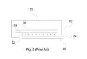
PR polymers are dynamic holographic recording materials. As shown in FIG. 5, an embodiment of a recording device 20 includes a layer of PR polymer material 22 sandwiched between a ground electrode 24 on an electrode support 26 and a high-voltage electrode 28 on an electrode support 30. A high-voltage power supply 32 applies a voltage between ground electrode 24 and high-voltage electrode 28 to provide a bias electric field 34 across the PR polymer.
As shown in FIG. 6, in PR polymers, a three-dimensional refractive index pattern—a phase hologram 40 replicates the non-uniform interference pattern 42 formed by the two incident coherent light fields 44 and 46. This effect is based on the build-up of an internal space-charge field E s 48 due to selective transport and trapping of the photo-generated charges 50, and an electric field induced index change via the electro-optic effect. This process—in contrast to photochemical processes involved in photopolymer holograms—is fully reversible, as trapped charges can be de-trapped by uniform illumination. The erasability of the PR gratings allows for refreshing/updating of the holograms. In a typical PR material the holograms are viewed with the help of a reading beam, as long as the initial writing (recording) beams are present. When the writing beams are turned off, the hologram written in the PR polymer decays at a rate determined by the material properties and ambient temperature.
The quality of the PR polymer and the written hologram can be evaluated with respect to three parameters: sensitivity, diffraction efficiency and persistence. The sensitivity is usually defined as the first temporal derivative of the dynamic efficiency measurement at the origin divided by the writing beams power. However, it is sometime more convenient to use the notion of writing time. Writing time and sensitivity are related quantities. As shown in FIG. 7, in continuous wave illumination, the writing time Tw is simply how long the writing beams must illuminate the media to achieve the desired diffraction efficiency of the hologram. The diffraction efficiency 82 is defined as the ratio between the intensity of the diffracted beam and the incident beam. In theory, PR polymers can achieve up to 100% diffraction efficiency. The persistence is a measure of the rate of decay of the hologram.
Holographic 3D Displays
Holographic 3D displays are one application of re-writable holograms. Computer generated holographic 3D displays provide highly realistic images without the need for special eyewear, making them valuable tools for applications that require “situational awareness” such as medical, industrial, and military imaging. Current commercially available holographic 3D displays employ material like photopolymers or silver halide emulsion that lack image-updating capability, resulting in their restricted use and high cost. Dynamic updateable 3D holographic displays based on acousto-optic, liquid crystal display and MEMS based recording media have been demonstrated. Unfortunately, these devices do not have memory, and thus do not exhibit persistence of recorded images. The lack of persistence results in the requirement of update rates faster than 30 Hz to avoid image flicker. Since 3D images exhibit very high information content, this high refresh rate requirement currently limits real time holographic displays to small sizes or low resolution. Although updateable, PR polymers have not yet been used for 3D displays because of their long writing times and low persistence. The ultimate goal is to be able to write at high enough rates to provide near video capability. An interim goal is provide the capability to update holograms with reasonable write times, high diffraction efficiency and persistence long enough to view the display. To extend dynamic holographic 3D displays towards practical applications, alternative materials with high efficiency, reversible recording capabilities, memory, and significantly larger sizes are needed.
Integral Imaging
Integral imaging (also called integral photography) is an auto stereoscopic technique that allows reproduction of 3D images with a flat (2D) display. Auto stereoscopic means there is no need for the viewer to wear eyewear to see the 3D effect. This technique is summarized in FIG. 8 where an array of lenses 92 is placed in front of the regular flat display 90 (static or dynamic) to redirect the light coming from individual pixels 98 so the viewer see different information at different angles. Individual lenses 96 of the lens array cover a defined surface of the display 94. The vertical and horizontal resolution of this kind of 3D display is defined by the number of lenses per unit of surface. The angular resolution is defined by the number of individual pixels covered by an individual lens 96. There exist 3D cards and 3D television systems based on this principle.
It has to be noted that horizontal parallax only (HPO) system can be achieved if the spherical lens array 92 is replaced by a cylindrical lens array. In this case, the 3D effect is only seen in one dimension (horizontal if cylindrical lenses axis is vertical). HPO is interesting since it did not degrade the vertical resolution of the display 90, and reduces the number of individual lenses 96. Since human vision relies mainly on the horizontal separation of both eyes to determine depth, vertical parallax can be ignored without degrading the 3D information too much.
Integral Holography
Holography can also be used for integral imaging (referred to as “integral holography”). In this case, what was a collection of individual pixels 94 is shrunk into a single holographic pixel (hogel) by a lens. The function of the individual lenses 96 that collimate the beams is also recorded as a hologram into the material. The advantage is that the resolution can be much higher than with a regular lens array and 2D display since the pixels and lens do not need any physical embodiment. The resolution limitation now comes from the optical recording setup resolution that is usually orders of magnitude higher than regular lens array resolution.
A typical integral holographic optical system using a grey-scale (single-color) transmission geometry is shown in FIG. 9. A laser 300 emits a coherent beam 310 that is split into a reference beam 320 and an object beam 330 by a beam splitter 340. The object beam is expanded by means of a telescope 350 and the beam's amplitude is structured by a device 360 that can be a transparent image, a mask, a spatial light modulator etc. The object beam is then resized by a telescope 370, directed by one or several mirrors 380, and focused by a lens 390 to the holographic recording material 400. That lens 390 is spherical in the case of full parallax and cylindrical in the case of horizontal parallax only. The reference beam 320 is shaped by optics 410 to match the shape of the object beam at the holographic material location, and directed by a mirror 420 to the holographic recording material. After one hogel has been recorded, the material is moved to the next hogel location by a translation stage 430. Controlling electronics 500 ensures the synchronization between the laser 300, the translation stage 430 and the device 360 that structures the object beam. In the case the device 360 that structures the object beam 330 is electronic; a memory 510 could be used to store the hogel data. During recording, the material is positioned or otherwise shielded so that the powerful writing beam is not incident on a viewer's eyes for safety.
When all the hogels have been recorded, the material is processed to develop the hologram (if needed) and moved to the reading position 440, where a reading source 450 emits a light beam 460 that is expanded by a telescope 470 and diffracted by the hologram 440 in a diffracted beam 480 toward the viewer's eyes.
In the case of a refreshable holographic recording material, when the hologram needs to be erased, the holographic recording device 400 is moved to the erasing location, where the erasing process occurs. In the case of erasure by light, like with photorefractive materials, an erasing light source 600 emits a beam 610 that is expanded with a telescope 620 and illuminates the whole hologram area. Some materials need a heating process for the hologram to be erased. Some materials like photo thermo plastic need electrical charging and heating the material to erase the hologram. Once erased, the recording material is moved back to the recording position.
SUMMARY OF THE INVENTION
The following is a summary of the invention in order to provide a basic understanding of some aspects of the invention. This summary is not intended to identify key or critical elements of the invention or to delineate the scope of the invention. Its sole purpose is to present some concepts of the invention in a simplified form as a prelude to the more detailed description and the defining claims that are presented later.
The present invention provides methods of recording holograms that reduce the writing time, increase the diffraction efficiency, improve the resolution, or restitute color. These techniques are well suited for use with an updateable 3D holographic display using integral holography and photorefractive polymer.
A system for recording a hologram includes a laser that produces a coherent beam and a holographic recording material. The laser beam is split into an object beam and a reference beam. The intensity of the object beam is spatially structured with information to write a hologram or part of a hologram in case of holographic stereogram. A beam steering mechanism steers the encoded object beam and reference beam to interfere at the holographic recording material to record the hologram or sequence of holograms.
In an embodiment in which the holographic recording material comprises a photorefractive (PR) polymer, a holographic optical element (HOE) diffracts one of the object or reference beams to reduce the angle between the grating vector and the external dielectric field and increase the diffraction efficiency of the PR polymer. In one configuration the HOE is configured to allow one of the object or reference beams to pass there through and to diffract the other beam to reduce the angle between the grating vector and the external electric field to increase the diffraction efficiency of the PR polymer.
In an embodiment in which the system is configured for a transmission geometry and recording a full-parallax holographic stereogram, a first lens array focuses the object beam on the recording material at multiple positions. The object beam is spatially structured so that each position corresponds to the correct hogel data. A second lens array splits the reference beam into multiple reference beams that are directed to the first lens array that collimates the multiple reference beams. If the beams overlap each other at the second lens array, the array is implemented as a HOE including an angularly selective grating to let the object beam pass unaffected while splitting and redirecting the reference beams. The second lens array may be implemented as a HOE that also diffracts the reference beams to reduce the angle between the grating vector and the external dielectric field and increase the diffraction efficiency of the PR polymer. The multiple object and multiple reference beams interfere at the multiple positions on the material to write multiple hogels simultaneously. The lens arrays may also be configured for HPO or reflective geometry as well.
In an embodiment in which the object and reference beams interfere at multiple locations that are spaced apart on an x-y grid to spatially multiplex the recording of the holography, the first and second lens arrays may be translated along a single axis at an oblique angle to the x-axis to write multiple holograms over the entire surface of the recording material as a series of parallel rows. This is an effective scanning system using only one translation direction and a fixed sample.
In an embodiment in which a color hologram is recorded using integral holography in transmission geometry, a spatial light modulator (SLM) having different zones is loaded with hogel data for different colors to spatially structure the object beam and form the modulated object beam. A focusing lens redirects the different zones of the modulated object beam at correct angles of incidence for each color towards the recording material such that diffraction of multiple color reading beams through the recording material produces multiple object beams with different colors that superimpose at a common viewer position.
In an embodiment in which the holographic recording material comprises a photorefractive (PR) polymer in a system for multiplexed recording of color holographic stereogram in a transmission geometry, a first optical system separate the laser beam into reference and object beams having both orthogonal polarization components (horizontal and vertical or circular left and right polarizations). A second optical system splits the object beam into first, second and third object beams. The first and second object beams have one polarization component and the third object beam has the orthogonal polarization component. The first and second object beams are positioned to have a symmetrical angle of incidence so that the grating vector of a hologram formed by cross-talk is perpendicular to the external electric field applied to the material so that the diffraction efficiency is near zero. The angles of incidence for all three object beams satisfy the Bragg equation so that when, for example, each hologram is read with a different color it displays a full color hologram in the direction of the audience.
In an embodiment in which the hologram is recorded using integral holography for a display, a holographic element is positioned after the recording material to redirect the reading beam diffracted by the hologram approximately orthogonal to the recording material toward the viewer position to provide a more natural look at the display. Positioning a holographic lens after the material changes the orientation of the cones of light diffracted by the hogels. The lens may be designed so that rays of light entering the viewer pupil have the same angles inside the cone of light for each hogel and the correct part of the hogel is perceived rendering the correct image with the viewer located at a specified finite distance.
In an embodiment in which the hologram is recorded using integral holography for a display and the modulated object beam is spatially structured with hologram data for multiple holograms, a first HOE splits and diffracts the reference beam into multiple reference beams, a second HOE collimates the multiple reference beams and focuses the object beam so that the multiple object and multiple reference beams interfere at multiple positions on the material to write multiple holograms simultaneous, and a third HOE positioned after the recording material to redirect a reading beam transmitted through the recording beam approximately orthogonal to the recording material toward a viewer position to provide a more natural look at the display.
In an embodiment in which the system uses integral holography in a full-parallax transmission geometry to record and display holograms, a mask/mirror is positioned between the laser and the holographic recording material. The mask mirror comprises an aperture that defines the extent of a hogel and a mirror surface facing the recording material. A translation stage moves the mask/mirror to synchronize the position of the aperture with the location of the steered object and reference and beams. A read source is positioned on the opposite side of the recording material to direct the reading beam through the material where it reflects off the mirrored surface and is transmitted back through the hologram in the material where it is diffracted to produce the diffracted beam. A filter may be positioned between the recording material and the viewer to absorb the object and reference beams that may pass through the material.
In an embodiment in which the system is configured to record hologram(s) on a dynamic holographic recording material comprising a PR polymer, the object beam is used to simultaneously erase the structure of the previous hologram and write the current hologram. The laser power is high enough to erase the previous hologram without leaving a ghost image and low enough to record the current hologram without causing a permanent set. In a configuration, the object beam reduces the diffraction efficiency of the previous hologram to less than 20% when writing the current hologram.
In an embodiment for the display of holograms in an HPO geometry, the horizontal and vertical image planes need to be disassociated during the holographic recording. The best resolution happens when the vertical image plane is at the holographic recording material position and the horizontal image plane is near the Fourier cylindrical lens position. The object beam is shaped by a spherical lens and then collimated with a spherical mirror at an angle. The natural astigmatism of the spherical mirror is used to disassociate the image plane so the horizontal image plane is near a Fourier cylindrical lens and the vertical image plane is near the holographic recording material.
In an embodiment in which the holographic recording material comprises a PR polymer, a pair of interleaved electrodes is deposited on one surface of the PR polymer. With such a pattern, the orientation of the electric field is parallel to the sample surface if the sample is thin compared to the space between the electrodes. If the plane of incidence (plane comprising both writing beams) has a component parallel to the field vectors, the grating vector will also have a component along the electric field and the photorefractive effect will occur.
These and other features and advantages of the invention will be apparent to those skilled in the art from the following detailed description of preferred embodiments, taken together with the accompanying drawings, in which:
BRIEF DESCRIPTION OF THE DRAWINGS
FIG. 1, as described above, is a diagram of a transmission geometry for forming a hologram;
FIG. 2, as described above, is a diagram of a reflection geometry for forming a hologram;
FIG. 3, as described above, is a diagram of a transmission geometry for reading a hologram;
FIG. 4, as described above, is a diagram of a reflection geometry for reading a hologram;
FIG. 5, as described above, is a diagram a recording device using a photorefractive polymer material;
FIG. 6, as described above, is a diagram illustrating the photorefractive effect;
FIG. 7, as described above, is a diagram of the diffraction efficiency during a write and dark decay;
FIG. 8, as described above, is a diagram illustrating an integral imaging technique for reproducing 3D images with a 2D display;
FIG. 9, as described above, is a diagram of an integral holographic setup for writing, reading and erasing holograms;
FIG. 10 is a diagram of a holographic optical element for improving diffraction efficiency in accordance with an embodiment of the invention;
FIGS. 11, 12 and 13 are diagrams illustrating the use of holographic optical elements to multiplex the recording of the hologram in accordance with an embodiment of the invention;
FIGS. 14, 15 and 16 are diagrams for a single axis scanning system for full surface recording of a pixilated holographic display in accordance with an embodiment of the invention;
FIGS. 17 and 18 are diagram of a multiplexed recording of a color hologram in accordance with an embodiment of the invention;
FIGS. 19 a and 19 b are diagrams of different embodiments of a symmetrical geometry to simultaneously record a multiplexed hologram in a photorefractive media is a diagram of a multiplexed recording of a color hologram in accordance with an embodiment of the invention;
FIGS. 20, 21 and 22 are diagrams illustrating the use of a holographic element for view plane compensation in accordance with an embodiment of the invention;
FIG. 23 is a diagram of a retroflector for simultaneous writing and reading for a transmission geometry in accordance with an embodiment of the invention;
FIG. 24 is a diagram of simultaneous erasing and writing of a hogel in accordance with an embodiment of the invention;
FIGS. 25 and 26 are diagrams of a reflective off-axis telescope for resolution improvement in a horizontal parallax only (HPO) geometry in accordance with an embodiment of the invention;
FIGS. 27, 28 and 29 are diagrams of an interleaved electrode for external field application in photorefractive polymer material in accordance with an embodiment of the invention; and
FIG. 30 is diagram of holographic system employing three HOEs to multiplex the recording of the hologram, improve the diffraction efficiency and provide for view plan compensation.
DETAILED DESCRIPTION OF THE INVENTION
The present invention provides methods of recording holograms that reduce the writing time, improve the resolution, increase the efficiency, or restitute color. These techniques are well suited for use with an updateable 3D holographic display using integral holography. These techniques may be used individually or in combination.
In photorefractive polymer materials the diffraction efficiency strongly depends on the angle between the grating vector and the external applied field direction. The grating vector is perpendicular to the bisector of the object and reference beams inside the recording material. The diffraction is minimum when this angle is 90° and maximum when this angle is 0°. This is due to the charge transport mechanism that is governed by drift. When using a PR polymer it is important to minimize this angle to optimize the diffraction efficiency. For transmission gratings, this is achieved by using a non-symmetrical geometry where the sample is tilted according to the bisector formed by the object and reference beams. However, for some applications, there exist constraints on the geometry, and this angle is limited to a certain value. This is the case for a 3D display where there is optics obstruction in the recording setup.
A holographic optical element (HOE), or a combination of such elements, redirects the beams near the sample to increase the incident angle without changing the holographic recording setup main optics. As show in FIG. 10, a holographic optical element 102 (e.g. a diffraction grating) is designed and positioned so that a writing beam 106 is diffracted toward a PR material 100 while the other recording beam 104 passes through element 102 without being diffracted. This can be achieved by using a highly angular selective diffraction grating. In this geometry, the grating vector 107 into the holographic recording material is redirected at a shallower angle considering the device external field vector 108. This reduces the angle between the grating vector and the external electric field to increase the diffraction efficiency of the material. In an alternate embodiment, HOE 102 may be positioned so that only the diffracted writing beam 106 passes there through. The writing beam may be either object beam or the reference beam.
A holographic optical element 112 may be used in combination with a lens array to multiplex the holographic recording in order to reduce the recording time. The technique of integral imaging by holographic recording requires the whole display surface to be filled with holographic pixels. In the case of large surface and good resolution, a large number of pixels need to be recorded. Recording multiple pixels at once (spatial multiplexing) is a way to reduce the recording time.
FIG. 11 shows how a lens array (HOE or other) 112 that refracts (diffracts) a first writing beam 114 (e.g. the object beam) into multiple writing beams 116 incident on a sample 110. The writing beam or beams may be modulated with a single SLM that is spatially structured to coincide with the multiple writing beams or with multiple SLMs, one for each writing beam. To effectively write multiple holograms into the sample, the second writing beam (the reference beam) must also be incident to the sample and overlap the first beam spots. If the second beam is uncorrected, it will pass through the lens array 112 and be focused outside the spots of the first beam.
As shown in FIG. 12, to compensate for that misalignment, a second lens array (refractive or HOE) 122 is introduced into the path of a second writing beam 120 (e.g. the reference beam) and refracts (diffracts) the beam into multiple reference beams 124 at the correct angle. When these second writing beams 124 pass through the lens array 112, the beams are redirected as beams 126 to the same spots where the first beams 116 are focused at the sample location 110.
To optimize the image quality for integral holography purpose, the second beams 126 may be collimated when incident to the sample and the spot size at the sample location should match the spot size of the first beams 116. To achieve both functions, the lens arrays 112 and 122 should work as a telescope so the diameter of the beams 126 matches the diameter of the beams 116 at the sample location (see FIG. 13).
To overcome the problem of obstruction of the lens array 122 for the first beam 114, the lens array can be replaced by a HOE comprising an angular selective grating that only diffracts the beam coming at a specific angle. Beam 120 is oriented accordingly so it is diffracted and focused by the HOE while beam 114 passes through, unaffected (see FIG. 13).
In case of horizontal parallax only geometry, the lens arrays are constituted of vertical cylindrical lenses. In case of full parallax, the lens arrays are constituted of spherical lenses.
This system can be used in conjunction with the HOE designed for efficiency improvement. The holographic element that redirects the reference beam to improve diffraction (element 102 FIG. 10) and the one that focuses the reference beam (element 122 FIG. 13) can be combined into a single HOE that performs both those functions. In FIG. 13, the object beam is horizontal for the sake of clarity instead of tilted as presented in FIG. 10. The benefit of this combination is more compact setup with less optical surfaces.
As presented in FIG. 14, in the case of spatial multiplexing, in horizontal parallax only configuration, the horizontal displacement of the lens array 112 and the holographic element 122 is enough to cover the entire surface of the recording material 140 with hogels 150 as a series of parallel rows and record the full hologram.
As shown in FIG. 15, if the same horizontal displacement 154 is conserved for full parallax geometry in which the object and reference beams interfere at multiple positions that are spaced apart on an x-y grid to spatially multiplex the recording of the holography, another vertical translation axis 152 is necessary to cover the whole area of the sample 140 with square hogels 150 in a raster scan mode.
As shown in FIG. 16, the lens arrays 112 and 122 may be translated along a single axis at an oblique angle to the x-axis write the hogels 130 over the entire surface of a recording material 140 as a series of parallel rows 150. This is an effective scanning system using only one translation direction and a fixed sample; there is no need to move the sample as shown in FIG. 9. The only condition is that there is a group of spare pixels 156 on the side of the sample to cover the whole area of the sample.
Color transmission holograms can be made (among other techniques) by angular multiplexing several transmission holograms that will diffract specific color when replayed. Recording angles are selected so the Bragg grating equation is fulfilled when replayed with a different wavelength than the recording wavelength. The angle should also be such that the diffracted beams coming from the different holograms superimpose on each other so the viewer sees the different views as a single colored hologram.
A known technique for recording an angular multiplexed hologram in which only the chief ray is drawn for the sake of clarity is shown in FIG. 17. A laser light source 170 emits a coherent light beam 172. Beams splitters 190 separate the beam into one (or several) reference beam 174 and several object beams 176, 178 and 180. Mirrors 192 reorient the different beams so they interfere at the holographic recording material location 182. The different object beams are modulated with separated devices (spatial light modulator) 184, 186, and 188 to encode the color information.
To make the optical system more compact, different portions of the spatial light modulator may be dedicated for different colors in accordance with the invention. As shown in an embodiment in FIG. 18, the lenslet array has been reduced to one single lens and a single SLM is used to write the 3 colors. A laser light source 200 emits a coherent beam 202 that is split into a reference beam 206 and an object beam 208. The object beam is expanded by the means of a beam expander 210 (aka two lenses) to fit the spatial light modulator device 214 size. The spatial light modulator is divided in three different zones 216, 218, and 220 corresponding to different holograms to be multiplexed. The different zones are loaded with hogel data for the three different colors to spatially structure the object beam. A focusing lens 224 (e.g. a holographic optical element) redirects the different portions of the object beam 226, 228, and 230 at the correct angles toward the holographic recording material 232.
To read the three holograms responsible for the three colors, three colored reading beams are transmitted through the recording material where they are diffracted to reproduce the three object beams. However, since the colors of the reading beams are different from the color of the writing beam, the diffracted angles are not identical to the writing angles on account of spectral dispersion. If the object beams incident on the recording material were parallel during recording, the diffracted object beams will diverge from each other during display and the colors will not superimpose at a common viewer position but instead will be seen at different viewer positions. To correct for this, the object beams must have a different angle predetermined by the Bragg law. Those angles referred to above as the “correct angles” can be imposed to the object beam by using the focusing lens 224 that redirects the spatially separated parallel beams. That spatial separation (structure) can be achieved by using different zones of one single SLM.
Element 224 from FIG. 18 can be the same as element 112 from FIG. 13. In this particular case, color and multiplexing are combined together to write several hogels at once that will reproduce color.
Full color holograms can be generated by integral holography by recording three holograms one for each fundamental color (red green and blue). One approach is to use three separate writing lasers, one for each color. Depending on the recording geometry, different techniques can be used. In transmission geometry, angular multiplexing can be used with a single laser source to successively record the three holograms. However, in the case of a dynamic material such as a photorefractive material, the successive hologram erases (at least partially) the preceding one, leading to a decrease in diffraction efficiency. To simultaneously write two or more holograms, the recording beams that belong to different holograms should not interfere with each other. Otherwise, interferences and undesirable holograms are written that produce color cross-talk and decrease the overall diffraction efficiency. In this case the beam is separated into reference and object beams having both polarization components (horizontal and vertical or circular left and right polarizations). The object beam is split and polarized to produce three object beams that are incident at different angles to the media. To avoid cross talk between the resulting holograms, two of the object beams have orthogonal polarization. The third beam, which must have one of the two polarizations, is positioned at an angle of incidence to take advantage of the fact that photorefractive polymers do not record holograms if the vector is orthogonal to the external electric field. Each object beam is encoded with hogel data for one of the primary colors. This can be done with a dedicated SLM for each object beam or with a single SLM that is spatially structured to modulate all of the object beams simultaneously.
An embodiment of a recording geometry with angular and polarization diversity is presented in FIG. 19 a, a single laser source 1500 emits a coherent light beam 1502 that is split into 4 recording beams 1504, 1506, 1508 and 1510 with the appropriate optical elements (e.g. polarizing beam splitters and wave plates). Those beams interfere into the photorefractive polymer material 1512 that has electrical electrodes 1514 and 1616 on opposing surfaces (see FIG. 5). For example, an optical system splits beam 1502 into reference beam 1510 containing both orthogonal polarizations and the object beam and a second optical system splits the object beam into three different object beams 1504, 1506 and 1508. Beams 1504 and 1508 have the same polarization and are incident to the sample with opposite angles according to the surface normal so that the grating vector of a hologram formed by cross-talk is perpendicular to the external electric field applied to the material. Beam 1506 has the orthogonal polarization to beams 1504 and 1508. Polarization can be selected and changed with the appropriate optical elements (e.g. polarizing beam splitter and wave plates). The orthogonal polarizations may be horizontal and vertical or circular left and circular right, for example. With this configuration, there are three holograms that will be simultaneously recorded. Those are constituted with the following pair of beams: 1510/1504, 1510/1506 and 1510/1508. There is no interference between beams 1506 and 1504 or 1508 since their polarization is orthogonal. There is interference between beams 1504 and 1508 but the efficiency is negligible since the grating vector is perpendicular to the external electric field of the PR material. The angles of incidence for all three object beams satisfy the Bragg equation so that when each hologram is read with a different color it displays a full color hologram in the direction of the audience.
Another embodiment of a recording geometry with angular and polarization diversity is presented in FIG. 19 b, a single laser source 1250 emits a beam 1255 having both polarizations that is split, polarized and reflected off a series of beam splitters 1260, polarizers 1265 and mirrors 1270 to produce three object beams and two reference beams with the specified polarizations and angles of incidence. The two object beams have orthogonal polarizations to prevent their interference. Among the three object beams, the central one 1640 have one polarization and both external ones 1620 and 1630 have the orthogonal polarization. They are directed along the viewing direction of the display (horizontal). Since angular correction needs to be applied for the three colors to superimpose in the direction of the viewer, the three object beams have different angles according to the pulsed laser wavelength and the color the particular hologram should reproduce. In the case of a doubled YAG laser emitting at 532 nm (green), and a horizontal viewing direction for a red green and blue display (RGB), the horizontal object beam 1640 and the reference beam 1610 are recording the “green hologram”. In this case “green hologram” means that it is the color that the hologram will reproduce toward the viewer direction. Since a shift toward longer wavelengths (red) between the recording and the reading wavelength increases the diffraction angle, the angle between the object and reference beams for the “red hologram” should be smaller. Thus, the object beam 1620 and the reference beam 1600 should record the “red hologram”. Conversely, the object beam 1630 that is at larger angle, and the reference beam 1600 should record the “blue hologram”. Depending of the holographic material properties (thickness and index modulation), both those holograms (blue and red) could diffract the “wrong color”, i.e. the blue hologram diffracting red reading beam and the red hologram diffracting blue reading beam. However those colors will be directed at larger and smaller angle compare the direction of the viewer (horizontal) and will not be perceived by the viewer. The fact that the angle between the object beams 1620 and 1630 is symmetrical according to the electrodes of the photorefractive device prevents those beams to write an efficient diffraction grating even though they have the same polarization.
The advantages of this method are that there is only one laser source, recording is done simultaneously; there is no cross talk between holograms when replayed. There are three independent holograms so color could be coded on each different one for full color reproduction.
This technique can be used alone or in conjunction with other cases described in the document. This technique may be combined with the case where different zones of the same SLM are dedicated for different colors; a polarizer can be used on the top of the different SLM zones to rotate the polarization as needed. The advantage of this combination is only one SLM is needed to write the entire hologram reproducing color. The technique may be combined with the case where each multiplexed cone can contain the 3 beams (top, middle, and bottom) to record the 3 colors. The advantage of this combination is multiplexing number of holograms while including color reproduction there is so a spatial AND angular multiplexing.
As shown in FIG. 20, the use of an HOE to increase the diffraction efficiency has a potential disadvantage. When reading the hologram from holographic recording material 2001, the reading beam 2000 is diffracted at a sharp angle 2002. This is an inconvenience for a natural look at the display. To compensate for this effect, a holographic optical element 2003 may be added and positioned after the holographic recording material 2001 to redirect the beam 2004 approximately orthogonal to the material toward the viewer position 2005.
The use of a holographic element has yet another advantage in integral imaging/holography. For accurate reproduction of the 3D image, the light rays coming from different lenslets/hogels should provide the correct information at the correct angle. However, when no correction is applied as shown in FIG. 21, the reading beam 2100 is diffracted by the holographic recording material 2110 and more specifically by each individual hogel 2120 as a cone of light 2160. When the viewer 2130 is located at a finite distance, the rays of light 2140 entering the pupil from different hogels have different angles 2050. This projects different parts of the 3D image and distorts the image unless the viewer is located at infinity.
As presented in FIG. 22, the introduction of a lens element 2260 (e.g. a HOE) after the holographic recording material 2220 changes the orientation of the cones of light 2270 diffracted by the hogels 2220. So, the rays of light 2240 entering the viewer pupil 2230 have the same angles 2250 inside the cone of light for each hogel, and the correct part of the hogel is perceived rendering the correct image with the viewer located at a finite distance. It has to be noted that the use of an off axis holographic lens is possible because of the steep angle of the diffracted beam coming out of the holographic recording material (see FIG. 20) since on axis holographic lens is not feasible. Thus, the use of a holographic lens, instead of a refractive lens, solves two problems at once: the angle of view and the image distortion.
In an embodiment, elements 2003 and 2260 are the same holographic optical element.
FIG. 30 shows an object beam 3010 being structured in several beams and focused in the holographic recording material 3020 by a holographic optical element (HOE) 3030. The reference beam 3040 is structured into several beams by HOE 3050 and then collimated by the HOE 3030. Object and reference beams (3090 and 3100 respectively) interfere into the holographic recording material 3020. HOE 3050 also diffracts the several reference beams to reduce the angle between the grating vector and the external electric field and increase the diffraction efficiency of the PR polymer. When the hologram has been recorded, a reading beam coming along the direction of the reference beam is diffracted along the direction of the object beam. That reading beam 3060 is inclined. To restore the view zone perpendicular to the screen HOE 3070 diffracts the reading beam 3060 into beam 3110 that is directed toward the viewer 3080.
Transmission hologram geometry requires the reading beam to go through the media. Typically the reading light originates from the opposite side of the sample than the viewer. In known 3D displays, the obstruction of the writing optics prevents the orientation of the reading beam correctly at the same location the hologram is recorded. The solution was to move the sample to a different location to achieve the reading of the hologram (see FIG. 9 in prior art). For a refreshable 3D display this is a drawback since the sample has to move each time the hologram needs to be refreshed. This technique is not possible for a fast refreshing rate.
As described previously the whole sample may be scanned (recorded) by moving the lenslet array and the holographic optical element instead of the sample (see FIG. 6). This only solves half of the problem but does not address the fact that the sample needs to be moved to a different reading position. As shown in FIG. 23, in an embodiment the reference 800 and object beam 810 interfere at the holographic recording material 820 position. A reading light source 840 positioned on the other side of the material emits a light beam 850 directed toward the material. The reading beam goes through the material, gets reflected by a mirror 860, and then is diffracted to reconstruct the hologram beam 870 toward the viewer direction. In order to let the writing beam pass through the mirror 860, an aperture 830 the size of the hogel 880 is made in the mirror. The mirror has the dual-function to act as a mask to precisely define the area on the material written by the write beam. Note that there could be multiple apertures for writing multiple hogels. A translation stage 885 moves the mirror, and more particularly aperture 830 in synchronization with the steering of the write beams to record the next hogel. The sample and the reading source do not need to move.
To prevent some light from the reading source to be seen by the viewer and potentially harm him, a wavelength selective device 890 can be put between the sample and the viewer to absorb or reflect the transmitted light from the writing beams. This can be achieved by an absorption filter, dielectric coating . . . . In this case the writing and reading wavelength should be different enough to be respectively transmitted and absorbed by the device.
In previous integral holographic setups (FIG. 9), erasing the previously recorded hologram was done with an independent part of the setup. A separate erase beam illuminates the entire holographic recording material to remove the previously recorded image so a new hologram can be recorded. This erasing function is important so there is no ghost image when a new hologram is displayed. Unfortunately erasing takes some time that is not compatible with a fast refreshing rate required by telepresence or other application. Erasing also required the material to be moved to another position to be illuminated by the erasing beam. This is not compatible with the scanning method for telepresence and other applications, the holographic recording material must remain static when the audience is looking at it, so the holographic recording material cannot move.
An approach to overcome this problem is to use the writing beam as the erasing beam. The writing beam simultaneously erases the previous hologram encoded into a hogel (line or line segment) and writes the current hologram. Based on the diffraction efficiency of the material, the power and intensity ratio of the write laser are tuned so that the writing beam completely erases the previous hologram (i.e. no ghost image) without creating a permanent set to the current hologram. If the power/intensity is too low, the beam will not completely erase the previous hologram. If the power/intensity is too high, the beam may permanently write the current hologram into the material so that it cannot be erased.
As shown in FIG. 24, in photorefractive media, the hologram diffraction efficiency 1000 rises according to the writing time and then decay when the writing beams are turned off (e.g. dark decay). When the erasing light illuminates the hologram, the diffraction efficiency decreases according to time 1010. To simultaneously write a new hologram and erase the old one, the writing beams of the second hologram are used to erase the first hologram. The efficiency of the second hologram 1020 rises when the efficiency of the first hologram 1010 decreases. In order to avoid any ghost image from the first hologram when replacing the second hologram, the first hologram efficiency should be at a minimum value compared to the efficiency of the second hologram (lower than 20%) when the recording is done. This technique can be applied to each single hogel in the case of integral holography.
For accurate reproduction of the 3D image in HPO (Horizontal-Parallax Only) geometry, the horizontal and vertical image plans need to be dissociated during the holographic recording. The best resolution happens when the vertical image plane is at the holographic recording material position and the horizontal image plane is near the Fourier cylindrical lens position.
As shown in FIG. 25, the separation of object beam 250 image planes has always been done in the holographic recording setup by using a cylindrical lens 254 at the focal point of an imaging system constituted of two cylindrical lenses 252 and 256. By carefully choosing the focal length of the lenses, the horizontal image plane is near the Fourier cylindrical lens 258 and the vertical image plane is near the holographic recording material 260. However, lens 254 provides a fixed separation of the image planes, which sometimes is difficult to match with the lens 258 parameters. Besides, large objective lenses in the refractive telescope (252 and 256) are usually associated with strong spherical aberrations and aberration-free large size objectives are extremely expensive.
In an embodiment, the cylindrical lenses are replaced with a reflective off axis telescope system composed of a spherical lens or combination of some, along with a spherical concave mirror. Concave mirrors are characterized by minimal spherical aberrations and are relatively inexpensive in large sizes compared to lenses.
Usually, a reflective telescope induces a lot of image astigmatism since it should be used in off-axis geometry to eliminate image obstruction by the input lenses. This fact is turned to advantage. The natural astigmatism provides the required separation of the image planes. FIG. 26 shows how the object beam 270 is shaped by a spherical lens 272 and then collimated with a spherical mirror 274 at an angle. The natural astigmatism of the spherical mirror 274 used at an angle is used to dissociate the image plane so the horizontal image plane is near the Fourier cylindrical lens 276 and the vertical image plane is near the holographic recording material 278.
Advantages provided by such a system are minimal spherical aberrations for even large size holograms, the separation of image plane can be continuously tuned according to the orientation of the spherical mirror, and this system is relatively inexpensive.
Photorefractive polymer material needs an external applied field to generate the index modulation upon illumination. This is due to the charge transport mechanism. Moreover, the grating vector must have a component parallel to the field in order to drive charge from the bright regions where they are generated to the dark regions so they can be trapped.
Usually, as shown in FIG. 27, the field is applied by the means of a ground electrode 152 and a hot electrode 154 deposited on opposing surfaces of the photorefractive film 150 (field direction does not matter). Electrodes are electrically connected to a DC voltage supply 168. The field vector 156 is perpendicular to the film surface. To have a grating component along the electrical field direction, in a transmission hologram configuration, the sample is tilted according to the recording beam bisector 162. One talks of a slanted geometry; 158 and 160 are the recording beams and 164 is the grating vector (perpendicular to the beam bisector 162 inside the material). The index of refraction was not taken into account in the drawing for the sake of clarity.
In an embodiment, an interleaved electrode pattern is deposited on only one side of the sample. This geometry is described in FIG. 28 and FIG. 29 where two interleaved electrodes 172 and 174 are deposited on the top of the sample 170. Electrodes are connected to a DC voltage supply 184. The space between the electrodes, their width and length, as their number can vary according to the desired field intensity and the PR film size. With such a pattern, the orientation of the electric field is parallel to the sample surface if the sample is thin compared to the space between the electrodes. The direction of the field does not matter. If the plane of incidence (plane comprising both writing beams) has a component parallel to the field vectors 176, the grating vector 182 will also have a component along the electric field and the photorefractive effect should happen. As shown in FIG. 29, a passive layer of dielectric material 186 can also be coated between the electrodes and the PR polymer material as a buffer layer to prevent charges from the PR material to directly contact the electrode.
In another embodiment, an interleaved electrode pattern is placed in between two layers of photorefractive material. This can be done by depositing a first layer of PR material on a substrate then coating and etching the electrodes on the top of it and finally placing a second layer of PR material on the top of the electrodes. The advantage of that configuration is that the electric field is symmetrical in regard of the electrode plan; so the field on the top as the field on the bottom of the electrode plan will participate to the PR effect doubling the diffraction efficiency of the device. A passive layer of dielectric material can also be coated between the electrodes and the PR polymer material as a buffer layer to prevent charges from the PR material to directly contact the electrode and reduce the change of electrical shortcut inside the PR material.
Advantages of this geometry are multiple. The field intensity can be varied according to the electrode geometry. There is only one side of the sample that has electrodes. If the plane of incidence of the writing beams is exactly perpendicular to the electric field, the grating vector is also exactly perpendicular to the electric field that should enhance the material index modulation and improve the diffraction efficiency. This configuration cannot be achieved with the slanted transmission geometry.
While several illustrative embodiments of the invention have been shown and described, numerous variations and alternate embodiments will occur to those skilled in the art. Such variations and alternate embodiments are contemplated, and can be made without departing from the spirit and scope of the invention as defined in the appended claims.

Claims (14)

We claim:
1. A holographic recording system, comprising:
a holographic recording material comprising a photorefractive (PR) polymer;
an electrode structure for receiving a voltage to apply an external electric field to the PR polymer;
a laser that produces a coherent beam;
a beam splitter that splits the coherent beam into an object beam and a reference beam, the intensity of the object beam is spatially structured with data for writing a hologram to form a modulated object beam;
a beam steering mechanism that steers the modulated object beam and the reference beam relative to the holographic recording material to interfere at different places in the material to record one or more holograms, said modulated object beam and said reference beam producing a grating vector at an angle to the external electric field that controls a diffraction efficiency of the PR polymer;
a first lens array that focuses the object beam on the recording material at multiple positions, said object beam spatially structured so that each position on the recording material corresponds to correct hologram data;
a second lens array that splits the reference beam into multiple reference beams that are directed to the first lens array that collimates the multiple reference beams so that the multiple object and multiple reference beams interfere at the multiple positions on the material to write multiple holograms simultaneously; and
a first holographic optical element (HOE) that diffracts one of the object or reference beams to reduce the angle between the grating vector and the external electric field and increase the diffraction efficiency of the PR polymer.
2. The holographic recording system of claim 1, wherein the first HOE is configured to allow one of the object or reference beams to pass there through unaffected and to diffract the other one of the object or reference beams.
3. The holographic recording system of claim 1, wherein the second lens array is a second HOE comprising an angularly selective grating.
4. The holographic recording system of claim 1, further comprising:
a second holographic optical element (HOE) that focuses the object beam on the recording material at multiple positions, said object beam spatially structured so that each position corresponds to the correct hologram data;
wherein said first HOE splits by diffraction the reference beam into multiple reference beams that are directed to the second HOE that collimates the multiple reference beams so that the multiple object and multiple reference beams interfere at the multiple positions on the material to write multiple holograms simultaneously.
5. The holographic recording system of claim 1, wherein the hologram is recorded using integral holography to form a display, further comprising:
a reading beam that is diffracted by the holographic recording material at an angle; and
a second holographic optical element (HOE) positioned after the recording material to redirect the diffracted beam approximately orthogonal to the recording material toward a viewer position.
6. The holographic system of claim 1, wherein said object and reference beams interfere at multiple positions that are spaced apart on an x-y grid, said beam steering mechanism translating the first and second lens arrays along a single axis at an oblique angle to the x-axis to write multiple holograms over the entire surface of the recording material as a series of parallel rows.
7. The holographic recording system of claim 1, in which a color hologram is recorded using integral holography in a transmission geometry, further comprising:
a spatial light modulator (SLM) having different zones loaded with hogel data for different colors to spatially structure the object beam and form the modulated object beam; and
a focusing lens that redirects the different zones of the modulated object beam at correct angles of incidence for each color towards the recording material such that transmission of a color reading beam through the recording material produces multiple object beams at different colors that superimpose at a common viewer position.
8. The holographic recording system of claim 1, in which the system uses integral holography in a full-parallax transmission geometry to record and display holograms, further comprising:
a mask/mirror positioned between the laser and the holographic recording material, said mask/mirror comprising an aperture that defines the extent of an individual hogel in the hologram and a mirror surface facing the recording material;
a translation stage that moves the mask/mirror to synchronize a position of the aperture with the location of the steered object and reference beams; and
a read source positioned on the opposite side of the recording material to direct a reading beam through the material where the reading beam reflects off the mirrored surface and is transmitted back through the hologram in the material where the reading beam is diffracted to produce a diffracted beam to display the hologram.
9. The holographic recording system of claim 1 for the display of holograms in a horizontal parallax only (HPO) geometry in which horizontal and vertical image planes need to be disassociated during the holographic recording, further comprising:
a spherical lens that shapes the object beam; and
a spherical mirror positioned at an angle to the object beam, astigmatism of the spherical mirror disassociating an image plane so a horizontal image plane is near a Fourier cylindrical lens and a vertical image plane is near the holographic recording material.
10. The holographic recording system of claim 1 for recording of a color holographic stereogram in a transmission geometry, further comprising:
a first optical system to separate the coherent beam into the reference and object beams having both first and second orthogonal polarization components; and
a second optical system to split the object beam into first, second and third object beams, said first and second object beams having said first polarization component and said third object beam having said second polarization component, said first and second object beams positioned to have a symmetrical angle of incidence so that the grating vector of a hologram formed by cross-talk is perpendicular to the external electric field in the photorefractive material so that the diffraction efficiency is near zero;
wherein angles of incidence for all three object beams satisfy a Bragg equation so that when each hologram is read with a different color it displays a full color hologram in a direction of an audience.
11. The holographic recording system of claim 1, wherein the object beam is used to simultaneously erase the structure of a previous hologram and write a current hologram, the laser power being sufficiently high to erase the previous hologram without leaving a ghost image and low enough to record the current hologram without causing a permanent set.
12. The holographic recording system of claim 11, wherein the object beam reduces the diffraction efficiency of the previous hologram to less than 20% when writing the current hologram.
13. The holographic recording system of claim 1, wherein the electrode structure comprises a pair of interleaved electrodes deposited on only one surface of the PR polymer.
14. A holographic recording system, for recording a hologram using integral holography for a display, comprising:
a holographic recording material comprising a photorefractive (PR) polymer;
an electrode structure for receiving a voltage to apply an external electric field to the PR polymer;
a laser that produces a coherent beam;
a beam splitter that splits the coherent beam into an object beam and a reference beam, the intensity of the object beam is spatially structured with data for writing a hologram to form a modulated object beam;
a beam steering mechanism that steers the modulated object beam and the reference beam relative to the holographic recording material to interfere at different places in the material to record one or more holograms, said modulated object beam and said reference beam producing a grating vector at an angle to the external electric field that controls a diffraction efficiency of the PR polymer;
a first holographic optical element (HOE) that diffracts one of the object or reference beams to reduce the angle between the grating vector and the external electric field and increase the diffraction efficiency of the PR polymer;
a second holographic optical element (HOE) that focuses the object beam on the recording material at multiple positions, said object beam spatially structured so that each position corresponds to the correct hologram data, wherein said first HOE splits by diffraction the reference beam into multiple reference beams that are directed to the second HOE that collimates the multiple reference beams so that the multiple object and multiple reference beams interfere at the multiple positions on the material to write multiple holograms simultaneously; and
a third holographic optical element (HOE) positioned after the recording material to redirect a reading beam transmitted through the recording beam approximately orthogonal to the recording material toward a viewer position.
US13/041,407 2010-07-09 2011-03-06 System for holography Active 2032-04-19 US8634119B2 (en)

Priority Applications (1)

Application Number Priority Date Filing Date Title
US13/041,407 US8634119B2 (en) 2010-07-09 2011-03-06 System for holography

Applications Claiming Priority (2)

Application Number Priority Date Filing Date Title
US36316510P 2010-07-09 2010-07-09
US13/041,407 US8634119B2 (en) 2010-07-09 2011-03-06 System for holography

Publications (2)

Publication Number Publication Date
US20120008482A1 US20120008482A1 (en) 2012-01-12
US8634119B2 true US8634119B2 (en) 2014-01-21

Family

ID=45438513

Family Applications (1)

Application Number Title Priority Date Filing Date
US13/041,407 Active 2032-04-19 US8634119B2 (en) 2010-07-09 2011-03-06 System for holography

Country Status (1)

Country Link
US (1) US8634119B2 (en)

Cited By (31)

* Cited by examiner, † Cited by third party
Publication number Priority date Publication date Assignee Title
US20170212349A1 (en) * 2015-05-04 2017-07-27 Thalmic Labs Inc. Systems, devices, and methods for spatially-multiplexed holographic optical elements
US10012829B2 (en) 2014-06-25 2018-07-03 Thalmic Labs Inc. Systems, devices, and methods for wearable heads-up displays
US10031338B2 (en) 2015-02-17 2018-07-24 Thalmic Labs Inc. Systems, devices, and methods for eyebox expansion in wearable heads-up displays
US10073268B2 (en) 2015-05-28 2018-09-11 Thalmic Labs Inc. Display with integrated visible light eye tracking
US10126815B2 (en) 2016-01-20 2018-11-13 Thalmic Labs Inc. Systems, devices, and methods for proximity-based eye tracking
US10151926B2 (en) 2016-01-29 2018-12-11 North Inc. Systems, devices, and methods for preventing eyebox degradation in a wearable heads-up display
US10215987B2 (en) 2016-11-10 2019-02-26 North Inc. Systems, devices, and methods for astigmatism compensation in a wearable heads-up display
US10228558B2 (en) 2015-10-23 2019-03-12 North Inc. Systems, devices, and methods for laser eye tracking
US10230929B2 (en) 2016-07-27 2019-03-12 North Inc. Systems, devices, and methods for laser projectors
US10365492B2 (en) 2016-12-23 2019-07-30 North Inc. Systems, devices, and methods for beam combining in wearable heads-up displays
US10365550B2 (en) 2016-04-13 2019-07-30 North Inc. Systems, devices, and methods for focusing laser projectors
US10409057B2 (en) 2016-11-30 2019-09-10 North Inc. Systems, devices, and methods for laser eye tracking in wearable heads-up displays
US10437073B2 (en) 2017-01-25 2019-10-08 North Inc. Systems, devices, and methods for beam combining in laser projectors
US10459223B2 (en) 2016-08-12 2019-10-29 North Inc. Systems, devices, and methods for variable luminance in wearable heads-up displays
US10488662B2 (en) 2015-09-04 2019-11-26 North Inc. Systems, articles, and methods for integrating holographic optical elements with eyeglass lenses
US10528135B2 (en) 2013-01-14 2020-01-07 Ctrl-Labs Corporation Wearable muscle interface systems, devices and methods that interact with content displayed on an electronic display
US10598944B2 (en) * 2017-08-14 2020-03-24 Boe Technology Group Co., Ltd. Beam expanding structure and optical display module
US10656822B2 (en) 2015-10-01 2020-05-19 North Inc. Systems, devices, and methods for interacting with content displayed on head-mounted displays
US10684692B2 (en) 2014-06-19 2020-06-16 Facebook Technologies, Llc Systems, devices, and methods for gesture identification
US10802190B2 (en) 2015-12-17 2020-10-13 Covestro Llc Systems, devices, and methods for curved holographic optical elements
US10901216B2 (en) 2017-10-23 2021-01-26 Google Llc Free space multiple laser diode modules
US11079846B2 (en) 2013-11-12 2021-08-03 Facebook Technologies, Llc Systems, articles, and methods for capacitive electromyography sensors
US11635736B2 (en) 2017-10-19 2023-04-25 Meta Platforms Technologies, Llc Systems and methods for identifying biological structures associated with neuromuscular source signals
US11644799B2 (en) 2013-10-04 2023-05-09 Meta Platforms Technologies, Llc Systems, articles and methods for wearable electronic devices employing contact sensors
US11666264B1 (en) 2013-11-27 2023-06-06 Meta Platforms Technologies, Llc Systems, articles, and methods for electromyography sensors
US11797087B2 (en) 2018-11-27 2023-10-24 Meta Platforms Technologies, Llc Methods and apparatus for autocalibration of a wearable electrode sensor system
US11822110B2 (en) 2018-02-21 2023-11-21 University Of Utah Research Foundation Diffractive optic for holographic projection
US11868531B1 (en) 2021-04-08 2024-01-09 Meta Platforms Technologies, Llc Wearable device providing for thumb-to-finger-based input gestures detected based on neuromuscular signals, and systems and methods of use thereof
US11907423B2 (en) 2019-11-25 2024-02-20 Meta Platforms Technologies, Llc Systems and methods for contextualized interactions with an environment
US11921471B2 (en) 2013-08-16 2024-03-05 Meta Platforms Technologies, Llc Systems, articles, and methods for wearable devices having secondary power sources in links of a band for providing secondary power in addition to a primary power source
US11961494B1 (en) 2019-03-29 2024-04-16 Meta Platforms Technologies, Llc Electromagnetic interference reduction in extended reality environments

Families Citing this family (19)

* Cited by examiner, † Cited by third party
Publication number Priority date Publication date Assignee Title
KR101344028B1 (en) * 2011-10-19 2013-12-24 한국표준과학연구원 Apparatus and Method for manufacturing fine pattern using interferogram
KR101859663B1 (en) * 2011-11-24 2018-06-29 삼성전자주식회사 Holography device, three dimensional display holography display including the holography device and method of processing holography image
DE102012206594A1 (en) * 2012-04-20 2013-10-24 Leica Microsystems (Schweiz) Ag Microscope system with dynamic holographic image display unit
JP5975438B2 (en) * 2012-07-17 2016-08-23 国立研究開発法人情報通信研究機構 Electronic holographic display device
CN104076533A (en) * 2014-07-24 2014-10-01 哈尔滨工业大学 Method for improving performance of electrically-controlled diffraction device
US10448030B2 (en) * 2015-11-16 2019-10-15 Ostendo Technologies, Inc. Content adaptive light field compression
CN106125316B (en) * 2016-06-24 2018-09-11 西安电子科技大学 Energy saving nothing based on grating waveguide redirects image and integrates imaging display device
US10921236B2 (en) * 2016-07-20 2021-02-16 Imec Vzw Integrated lens free imaging device
WO2019094475A1 (en) * 2017-11-10 2019-05-16 The Arizona Board Of Regents On Behalf Fast and continuous recording of refreshable holographic stereograms
WO2019147512A2 (en) * 2018-01-21 2019-08-01 Ntt Docomo, Inc. Structure and manufacturing method of holographic optical elements
WO2019193120A1 (en) * 2018-04-06 2019-10-10 Essilor International Method for customizing a head mounted device adapted to generate a virtual image
DE102018132790A1 (en) * 2018-12-19 2020-06-25 HELLA GmbH & Co. KGaA Device and method for producing an edgelithologram, edgelithologram and lighting device for a vehicle
CN110187626B (en) * 2019-05-28 2021-03-16 京东方科技集团股份有限公司 Holographic optical device, holographic optical system, and holographic display system
CN112596262B (en) * 2020-12-14 2021-10-22 北京航空航天大学 Holographic true 3D display system and method based on adjustable liquid crystal grating
WO2023008691A1 (en) * 2021-07-29 2023-02-02 Samsung Electronics Co., Ltd. Method and system for simultaneous recording of superimposed holographic gratings for augmented reality devices (variants)
WO2023019196A1 (en) * 2021-08-11 2023-02-16 Arizona Board Of Regents On Behalf Of The University Of Arizona Control of probe beam duration in single wavelength monitoring of hologram diffraction efficiency
WO2023047145A1 (en) * 2021-09-23 2023-03-30 Lakatos Imre Method, computer program product and computer readable medium for creating a hologram
CN114237002B (en) * 2021-12-20 2022-09-16 北京邮电大学 System for generating image plane hologram
CN114995083B (en) * 2022-05-13 2023-07-28 四川大学 Cylindrical holographic display method based on planar spatial light modulator

Citations (8)

* Cited by examiner, † Cited by third party
Publication number Priority date Publication date Assignee Title
US5064264A (en) 1990-10-26 1991-11-12 International Business Machines Corporation Photorefractive materials
US5569565A (en) 1991-05-23 1996-10-29 Matsushita Electric Industrial Co., Ltd. Hologram recording material
WO2001045943A2 (en) 1999-12-10 2001-06-28 Geola Technologies Ltd. Holographic printer
US6281994B1 (en) 1998-12-22 2001-08-28 Nippon Telegraph And Telephone Corporation Method and apparatus for three-dimensional holographic display suitable for video image display
US20030156309A1 (en) * 2000-08-25 2003-08-21 Marko Zgonik Confocal holographic optical storage with non-overlapping records
US6806982B2 (en) 2001-11-30 2004-10-19 Zebra Imaging, Inc. Pulsed-laser systems and methods for producing holographic stereograms
US6859293B2 (en) 2002-10-22 2005-02-22 Zebra Imaging, Inc. Active digital hologram display
US20090168129A1 (en) * 2003-12-30 2009-07-02 Stx Aprilis, Inc. Replication of data to holographic medium using holographic master media

Patent Citations (11)

* Cited by examiner, † Cited by third party
Publication number Priority date Publication date Assignee Title
US5064264A (en) 1990-10-26 1991-11-12 International Business Machines Corporation Photorefractive materials
US5569565A (en) 1991-05-23 1996-10-29 Matsushita Electric Industrial Co., Ltd. Hologram recording material
US6281994B1 (en) 1998-12-22 2001-08-28 Nippon Telegraph And Telephone Corporation Method and apparatus for three-dimensional holographic display suitable for video image display
WO2001045943A2 (en) 1999-12-10 2001-06-28 Geola Technologies Ltd. Holographic printer
US20030156309A1 (en) * 2000-08-25 2003-08-21 Marko Zgonik Confocal holographic optical storage with non-overlapping records
US6806982B2 (en) 2001-11-30 2004-10-19 Zebra Imaging, Inc. Pulsed-laser systems and methods for producing holographic stereograms
US7027197B2 (en) 2001-11-30 2006-04-11 Zebra Imaging, Inc. Pulsed-laser systems and methods for producing holographic stereograms
US7505186B2 (en) 2001-11-30 2009-03-17 Zebra Imaging, Inc. Pulsed-laser systems and methods for producing holographic stereograms
US6859293B2 (en) 2002-10-22 2005-02-22 Zebra Imaging, Inc. Active digital hologram display
US7227674B2 (en) 2002-10-22 2007-06-05 Zebra Imaging, Inc. Active digital hologram display
US20090168129A1 (en) * 2003-12-30 2009-07-02 Stx Aprilis, Inc. Replication of data to holographic medium using holographic master media

Non-Patent Citations (6)

* Cited by examiner, † Cited by third party
Title
Blanche et al., "An Updatable Holographic Display for 3D Visualization," Journal of Display Technology, vol. 4, No. 4, Dec. 2008, pp. 424-430.
Blanche et al., "Holographic three-dimensional telepresence using large-area photorefractive polymer," 80 Nature, vol. 468, Nov. 4, 2010.
Hayasaki et al., "Thick photorefractive polymer device with coplanar electrodes," Review of Scientific Instruments, vol. 74, No. 8, Aug. 2003, pp. 3693-3696.
Oksana Ostroverkhova et al, Organic Photorefractives: Mechanisms, Materials and Applications, Chem Rev. 104, 3267-3314 Jun. 26, 2004.
Peyghambarian et al., "Rewritable Holographic 3D Displays," OPN Jul./Aug. 2008, pp. 23-27.
Tay et al., "An updatable holographic three-dimensional display," 2008 Nature Publishing Group, vol. 451, Feb. 7, 2008, pp. 694-698.

Cited By (66)

* Cited by examiner, † Cited by third party
Publication number Priority date Publication date Assignee Title
US11009951B2 (en) 2013-01-14 2021-05-18 Facebook Technologies, Llc Wearable muscle interface systems, devices and methods that interact with content displayed on an electronic display
US10528135B2 (en) 2013-01-14 2020-01-07 Ctrl-Labs Corporation Wearable muscle interface systems, devices and methods that interact with content displayed on an electronic display
US11921471B2 (en) 2013-08-16 2024-03-05 Meta Platforms Technologies, Llc Systems, articles, and methods for wearable devices having secondary power sources in links of a band for providing secondary power in addition to a primary power source
US11644799B2 (en) 2013-10-04 2023-05-09 Meta Platforms Technologies, Llc Systems, articles and methods for wearable electronic devices employing contact sensors
US11079846B2 (en) 2013-11-12 2021-08-03 Facebook Technologies, Llc Systems, articles, and methods for capacitive electromyography sensors
US11666264B1 (en) 2013-11-27 2023-06-06 Meta Platforms Technologies, Llc Systems, articles, and methods for electromyography sensors
US10684692B2 (en) 2014-06-19 2020-06-16 Facebook Technologies, Llc Systems, devices, and methods for gesture identification
US10067337B2 (en) 2014-06-25 2018-09-04 Thalmic Labs Inc. Systems, devices, and methods for wearable heads-up displays
US10054788B2 (en) 2014-06-25 2018-08-21 Thalmic Labs Inc. Systems, devices, and methods for wearable heads-up displays
US10012829B2 (en) 2014-06-25 2018-07-03 Thalmic Labs Inc. Systems, devices, and methods for wearable heads-up displays
US10613331B2 (en) 2015-02-17 2020-04-07 North Inc. Systems, devices, and methods for splitter optics in wearable heads-up displays
US10031338B2 (en) 2015-02-17 2018-07-24 Thalmic Labs Inc. Systems, devices, and methods for eyebox expansion in wearable heads-up displays
US20170212349A1 (en) * 2015-05-04 2017-07-27 Thalmic Labs Inc. Systems, devices, and methods for spatially-multiplexed holographic optical elements
US10133075B2 (en) 2015-05-04 2018-11-20 Thalmic Labs Inc. Systems, devices, and methods for angle- and wavelength-multiplexed holographic optical elements
US10175488B2 (en) * 2015-05-04 2019-01-08 North Inc. Systems, devices, and methods for spatially-multiplexed holographic optical elements
US10197805B2 (en) 2015-05-04 2019-02-05 North Inc. Systems, devices, and methods for eyeboxes with heterogeneous exit pupils
US10180578B2 (en) 2015-05-28 2019-01-15 North Inc. Methods that integrate visible light eye tracking in scanning laser projection displays
US10078220B2 (en) 2015-05-28 2018-09-18 Thalmic Labs Inc. Wearable heads-up display with integrated eye tracker
US10488661B2 (en) 2015-05-28 2019-11-26 North Inc. Systems, devices, and methods that integrate eye tracking and scanning laser projection in wearable heads-up displays
US10139633B2 (en) 2015-05-28 2018-11-27 Thalmic Labs Inc. Eyebox expansion and exit pupil replication in wearable heads-up display having integrated eye tracking and laser projection
US10073268B2 (en) 2015-05-28 2018-09-11 Thalmic Labs Inc. Display with integrated visible light eye tracking
US10078219B2 (en) 2015-05-28 2018-09-18 Thalmic Labs Inc. Wearable heads-up display with integrated eye tracker and different optical power holograms
US10114222B2 (en) 2015-05-28 2018-10-30 Thalmic Labs Inc. Integrated eye tracking and laser projection methods with holographic elements of varying optical powers
US10718945B2 (en) 2015-09-04 2020-07-21 North Inc. Systems, articles, and methods for integrating holographic optical elements with eyeglass lenses
US10705342B2 (en) 2015-09-04 2020-07-07 North Inc. Systems, articles, and methods for integrating holographic optical elements with eyeglass lenses
US10877272B2 (en) 2015-09-04 2020-12-29 Google Llc Systems, articles, and methods for integrating holographic optical elements with eyeglass lenses
US10890765B2 (en) 2015-09-04 2021-01-12 Google Llc Systems, articles, and methods for integrating holographic optical elements with eyeglass lenses
US10488662B2 (en) 2015-09-04 2019-11-26 North Inc. Systems, articles, and methods for integrating holographic optical elements with eyeglass lenses
US10656822B2 (en) 2015-10-01 2020-05-19 North Inc. Systems, devices, and methods for interacting with content displayed on head-mounted displays
US10228558B2 (en) 2015-10-23 2019-03-12 North Inc. Systems, devices, and methods for laser eye tracking
US10606072B2 (en) 2015-10-23 2020-03-31 North Inc. Systems, devices, and methods for laser eye tracking
US10802190B2 (en) 2015-12-17 2020-10-13 Covestro Llc Systems, devices, and methods for curved holographic optical elements
US10126815B2 (en) 2016-01-20 2018-11-13 Thalmic Labs Inc. Systems, devices, and methods for proximity-based eye tracking
US10241572B2 (en) 2016-01-20 2019-03-26 North Inc. Systems, devices, and methods for proximity-based eye tracking
US10303246B2 (en) 2016-01-20 2019-05-28 North Inc. Systems, devices, and methods for proximity-based eye tracking
US10151926B2 (en) 2016-01-29 2018-12-11 North Inc. Systems, devices, and methods for preventing eyebox degradation in a wearable heads-up display
US10437067B2 (en) 2016-01-29 2019-10-08 North Inc. Systems, devices, and methods for preventing eyebox degradation in a wearable heads-up display
US10451881B2 (en) 2016-01-29 2019-10-22 North Inc. Systems, devices, and methods for preventing eyebox degradation in a wearable heads-up display
US10365549B2 (en) 2016-04-13 2019-07-30 North Inc. Systems, devices, and methods for focusing laser projectors
US10365548B2 (en) 2016-04-13 2019-07-30 North Inc. Systems, devices, and methods for focusing laser projectors
US10365550B2 (en) 2016-04-13 2019-07-30 North Inc. Systems, devices, and methods for focusing laser projectors
US10277874B2 (en) 2016-07-27 2019-04-30 North Inc. Systems, devices, and methods for laser projectors
US10230929B2 (en) 2016-07-27 2019-03-12 North Inc. Systems, devices, and methods for laser projectors
US10250856B2 (en) 2016-07-27 2019-04-02 North Inc. Systems, devices, and methods for laser projectors
US10459221B2 (en) 2016-08-12 2019-10-29 North Inc. Systems, devices, and methods for variable luminance in wearable heads-up displays
US10459222B2 (en) 2016-08-12 2019-10-29 North Inc. Systems, devices, and methods for variable luminance in wearable heads-up displays
US10459223B2 (en) 2016-08-12 2019-10-29 North Inc. Systems, devices, and methods for variable luminance in wearable heads-up displays
US10215987B2 (en) 2016-11-10 2019-02-26 North Inc. Systems, devices, and methods for astigmatism compensation in a wearable heads-up display
US10345596B2 (en) 2016-11-10 2019-07-09 North Inc. Systems, devices, and methods for astigmatism compensation in a wearable heads-up display
US10409057B2 (en) 2016-11-30 2019-09-10 North Inc. Systems, devices, and methods for laser eye tracking in wearable heads-up displays
US10459220B2 (en) 2016-11-30 2019-10-29 North Inc. Systems, devices, and methods for laser eye tracking in wearable heads-up displays
US10663732B2 (en) 2016-12-23 2020-05-26 North Inc. Systems, devices, and methods for beam combining in wearable heads-up displays
US10365492B2 (en) 2016-12-23 2019-07-30 North Inc. Systems, devices, and methods for beam combining in wearable heads-up displays
US10718951B2 (en) 2017-01-25 2020-07-21 North Inc. Systems, devices, and methods for beam combining in laser projectors
US10437073B2 (en) 2017-01-25 2019-10-08 North Inc. Systems, devices, and methods for beam combining in laser projectors
US10437074B2 (en) 2017-01-25 2019-10-08 North Inc. Systems, devices, and methods for beam combining in laser projectors
US10598944B2 (en) * 2017-08-14 2020-03-24 Boe Technology Group Co., Ltd. Beam expanding structure and optical display module
US11635736B2 (en) 2017-10-19 2023-04-25 Meta Platforms Technologies, Llc Systems and methods for identifying biological structures associated with neuromuscular source signals
US11300788B2 (en) 2017-10-23 2022-04-12 Google Llc Free space multiple laser diode modules
US10901216B2 (en) 2017-10-23 2021-01-26 Google Llc Free space multiple laser diode modules
US11822110B2 (en) 2018-02-21 2023-11-21 University Of Utah Research Foundation Diffractive optic for holographic projection
US11797087B2 (en) 2018-11-27 2023-10-24 Meta Platforms Technologies, Llc Methods and apparatus for autocalibration of a wearable electrode sensor system
US11941176B1 (en) 2018-11-27 2024-03-26 Meta Platforms Technologies, Llc Methods and apparatus for autocalibration of a wearable electrode sensor system
US11961494B1 (en) 2019-03-29 2024-04-16 Meta Platforms Technologies, Llc Electromagnetic interference reduction in extended reality environments
US11907423B2 (en) 2019-11-25 2024-02-20 Meta Platforms Technologies, Llc Systems and methods for contextualized interactions with an environment
US11868531B1 (en) 2021-04-08 2024-01-09 Meta Platforms Technologies, Llc Wearable device providing for thumb-to-finger-based input gestures detected based on neuromuscular signals, and systems and methods of use thereof

Also Published As

Publication number Publication date
US20120008482A1 (en) 2012-01-12

Similar Documents

Publication Publication Date Title
US8634119B2 (en) System for holography
US11953683B2 (en) Display device, in particular a head-mounted display, based on temporal and spatial multiplexing of hologram tiles
US8264756B2 (en) Device for recording holograms
JP4576083B2 (en) Holographic display
KR101571174B1 (en) Holographic display having improved reconstruction quality
US9720375B2 (en) Spatial light modulating panel using transmittive liquid crystal display panel and 3D display device using the same
US5497254A (en) Optical apparatus including a liquid crystal modulator
US20110228040A1 (en) Auto Stereoscopic 3D Telepresence Using Integral Holography
JP5191491B2 (en) Small holographic display device
JP5222300B2 (en) Small holographic display device
US20110149018A1 (en) Holographic display device comprising magneto-optical spatial light modulator
US20090219595A1 (en) Device for Reading Out Holograms
KR20090027751A (en) Holographic projection device for the reconstruction of scenes
KR101894017B1 (en) Apparatus for manufacturing Holographic Optical Element, and apparatus for reconstruction of holograms
JP2010507954A (en) Mobile phone system with holographic display
CA2637751A1 (en) Projection device for the holographic reconstruction of scenes
CA2375460A1 (en) Holographic displays
US11169485B2 (en) Hologram displaying apparatus and method thereof
JP2014209247A (en) 3d content generation system, method thereof and communication method
US8325402B2 (en) System and method for synchronizing a spatial light modulator with a pulsed laser to record a hologram at the repetition rate of the pulsed laser
US6870651B2 (en) Apparatus and method for generating a dynamic image
KR100311910B1 (en) Stereo movie recording / playback device using volume holographic memory
KR20130053652A (en) Dynamic thin flat type light-beam deflector
Blanche et al. Continuous Recording of Holographic Stereograms
JP2838163B2 (en) How to display dynamic 3D images

Legal Events

Date Code Title Description
AS Assignment

Owner name: TIPD, LLC, ARIZONA

Free format text: ASSIGNMENT OF ASSIGNORS INTEREST;ASSIGNORS:BABLUMYAN, ARKADY;BLANCHE, PIERRE-ALEXANDRE JEAN;PEYGHAMBARIAN, NASSER N.;SIGNING DATES FROM 20110222 TO 20110303;REEL/FRAME:025906/0623

STCF Information on status: patent grant

Free format text: PATENTED CASE

AS Assignment

Owner name: GOVERNMENT OF THE UNITED STATES AS REPRESENTED BY

Free format text: CONFIRMATORY LICENSE;ASSIGNOR:TIPD, LLC;REEL/FRAME:040338/0216

Effective date: 20160307

FPAY Fee payment

Year of fee payment: 4

MAFP Maintenance fee payment

Free format text: PAYMENT OF MAINTENANCE FEE, 8TH YR, SMALL ENTITY (ORIGINAL EVENT CODE: M2552); ENTITY STATUS OF PATENT OWNER: SMALL ENTITY

Year of fee payment: 8