JP2014209247A - 3d content generation system, method thereof and communication method - Google Patents
3d content generation system, method thereof and communication method Download PDFInfo
- Publication number
- JP2014209247A JP2014209247A JP2014115312A JP2014115312A JP2014209247A JP 2014209247 A JP2014209247 A JP 2014209247A JP 2014115312 A JP2014115312 A JP 2014115312A JP 2014115312 A JP2014115312 A JP 2014115312A JP 2014209247 A JP2014209247 A JP 2014209247A
- Authority
- JP
- Japan
- Prior art keywords
- content
- light
- holographic
- generation system
- array
- Prior art date
- Legal status (The legal status is an assumption and is not a legal conclusion. Google has not performed a legal analysis and makes no representation as to the accuracy of the status listed.)
- Pending
Links
- 238000000034 method Methods 0.000 title claims abstract description 91
- 238000004891 communication Methods 0.000 title claims description 7
- 230000008569 process Effects 0.000 claims abstract description 36
- 238000012545 processing Methods 0.000 claims description 25
- 230000003068 static effect Effects 0.000 claims description 5
- 238000010422 painting Methods 0.000 claims description 2
- 239000010410 layer Substances 0.000 description 140
- 230000003287 optical effect Effects 0.000 description 77
- 230000010287 polarization Effects 0.000 description 42
- 239000004973 liquid crystal related substance Substances 0.000 description 38
- 239000011295 pitch Substances 0.000 description 37
- 238000005286 illumination Methods 0.000 description 34
- 230000005540 biological transmission Effects 0.000 description 30
- 230000006870 function Effects 0.000 description 29
- 210000004027 cell Anatomy 0.000 description 27
- 230000001427 coherent effect Effects 0.000 description 27
- 230000000875 corresponding effect Effects 0.000 description 23
- 239000000758 substrate Substances 0.000 description 23
- 238000010586 diagram Methods 0.000 description 21
- 238000009826 distribution Methods 0.000 description 21
- 230000000694 effects Effects 0.000 description 21
- 230000005684 electric field Effects 0.000 description 20
- 239000000463 material Substances 0.000 description 20
- 239000010408 film Substances 0.000 description 18
- 230000008901 benefit Effects 0.000 description 15
- 238000004364 calculation method Methods 0.000 description 14
- 239000000835 fiber Substances 0.000 description 14
- 230000002829 reductive effect Effects 0.000 description 14
- 238000003491 array Methods 0.000 description 13
- 238000004519 manufacturing process Methods 0.000 description 13
- 238000013459 approach Methods 0.000 description 11
- 230000000737 periodic effect Effects 0.000 description 11
- 238000005516 engineering process Methods 0.000 description 10
- 238000000926 separation method Methods 0.000 description 10
- 239000011521 glass Substances 0.000 description 9
- 238000003384 imaging method Methods 0.000 description 9
- 230000009467 reduction Effects 0.000 description 9
- 230000004888 barrier function Effects 0.000 description 8
- 230000008859 change Effects 0.000 description 8
- 238000001093 holography Methods 0.000 description 8
- 230000033001 locomotion Effects 0.000 description 8
- 239000012788 optical film Substances 0.000 description 8
- 238000006243 chemical reaction Methods 0.000 description 7
- 239000000243 solution Substances 0.000 description 7
- 230000002123 temporal effect Effects 0.000 description 7
- 201000009310 astigmatism Diseases 0.000 description 6
- BJQHLKABXJIVAM-UHFFFAOYSA-N bis(2-ethylhexyl) phthalate Chemical compound CCCCC(CC)COC(=O)C1=CC=CC=C1C(=O)OCC(CC)CCCC BJQHLKABXJIVAM-UHFFFAOYSA-N 0.000 description 6
- 238000013144 data compression Methods 0.000 description 6
- 230000006837 decompression Effects 0.000 description 6
- AMGQUBHHOARCQH-UHFFFAOYSA-N indium;oxotin Chemical compound [In].[Sn]=O AMGQUBHHOARCQH-UHFFFAOYSA-N 0.000 description 6
- 239000000853 adhesive Substances 0.000 description 5
- 230000001070 adhesive effect Effects 0.000 description 5
- 230000007423 decrease Effects 0.000 description 5
- 239000006185 dispersion Substances 0.000 description 5
- 230000004907 flux Effects 0.000 description 5
- 239000007788 liquid Substances 0.000 description 5
- 239000012044 organic layer Substances 0.000 description 5
- 210000001747 pupil Anatomy 0.000 description 5
- 230000005855 radiation Effects 0.000 description 5
- 230000009466 transformation Effects 0.000 description 5
- VYPSYNLAJGMNEJ-UHFFFAOYSA-N Silicium dioxide Chemical compound O=[Si]=O VYPSYNLAJGMNEJ-UHFFFAOYSA-N 0.000 description 4
- 238000013461 design Methods 0.000 description 4
- 238000001914 filtration Methods 0.000 description 4
- CNQCVBJFEGMYDW-UHFFFAOYSA-N lawrencium atom Chemical compound [Lr] CNQCVBJFEGMYDW-UHFFFAOYSA-N 0.000 description 4
- 239000011159 matrix material Substances 0.000 description 4
- ORQBXQOJMQIAOY-UHFFFAOYSA-N nobelium Chemical compound [No] ORQBXQOJMQIAOY-UHFFFAOYSA-N 0.000 description 4
- 230000001902 propagating effect Effects 0.000 description 4
- 230000035945 sensitivity Effects 0.000 description 4
- 230000003595 spectral effect Effects 0.000 description 4
- 238000001228 spectrum Methods 0.000 description 4
- 230000001360 synchronised effect Effects 0.000 description 4
- 125000002066 L-histidyl group Chemical group [H]N1C([H])=NC(C([H])([H])[C@](C(=O)[*])([H])N([H])[H])=C1[H] 0.000 description 3
- 239000003086 colorant Substances 0.000 description 3
- 238000000151 deposition Methods 0.000 description 3
- 238000001514 detection method Methods 0.000 description 3
- 239000005262 ferroelectric liquid crystals (FLCs) Substances 0.000 description 3
- 229920001690 polydopamine Polymers 0.000 description 3
- 238000004088 simulation Methods 0.000 description 3
- 230000000007 visual effect Effects 0.000 description 3
- YMHOBZXQZVXHBM-UHFFFAOYSA-N 2,5-dimethoxy-4-bromophenethylamine Chemical compound COC1=CC(CCN)=C(OC)C=C1Br YMHOBZXQZVXHBM-UHFFFAOYSA-N 0.000 description 2
- 239000004988 Nematic liquid crystal Substances 0.000 description 2
- 241000545067 Venus Species 0.000 description 2
- 230000001154 acute effect Effects 0.000 description 2
- 230000037237 body shape Effects 0.000 description 2
- 239000005388 borosilicate glass Substances 0.000 description 2
- 238000007906 compression Methods 0.000 description 2
- 230000006835 compression Effects 0.000 description 2
- 239000006059 cover glass Substances 0.000 description 2
- 210000002858 crystal cell Anatomy 0.000 description 2
- 238000005401 electroluminescence Methods 0.000 description 2
- 238000005538 encapsulation Methods 0.000 description 2
- 210000003128 head Anatomy 0.000 description 2
- 230000005764 inhibitory process Effects 0.000 description 2
- 230000010354 integration Effects 0.000 description 2
- 230000002452 interceptive effect Effects 0.000 description 2
- 230000031700 light absorption Effects 0.000 description 2
- 230000007246 mechanism Effects 0.000 description 2
- 239000013307 optical fiber Substances 0.000 description 2
- 230000036961 partial effect Effects 0.000 description 2
- 238000005070 sampling Methods 0.000 description 2
- 238000004904 shortening Methods 0.000 description 2
- 235000012239 silicon dioxide Nutrition 0.000 description 2
- 239000000377 silicon dioxide Substances 0.000 description 2
- 102100035473 2'-5'-oligoadenylate synthase-like protein Human genes 0.000 description 1
- RYGMFSIKBFXOCR-UHFFFAOYSA-N Copper Chemical compound [Cu] RYGMFSIKBFXOCR-UHFFFAOYSA-N 0.000 description 1
- 239000004593 Epoxy Substances 0.000 description 1
- 229910000530 Gallium indium arsenide Inorganic materials 0.000 description 1
- 101000597360 Homo sapiens 2'-5'-oligoadenylate synthase-like protein Proteins 0.000 description 1
- 239000004743 Polypropylene Substances 0.000 description 1
- 239000004793 Polystyrene Substances 0.000 description 1
- 229910052581 Si3N4 Inorganic materials 0.000 description 1
- HMDDXIMCDZRSNE-UHFFFAOYSA-N [C].[Si] Chemical compound [C].[Si] HMDDXIMCDZRSNE-UHFFFAOYSA-N 0.000 description 1
- 238000010521 absorption reaction Methods 0.000 description 1
- NIXOWILDQLNWCW-UHFFFAOYSA-N acrylic acid group Chemical group C(C=C)(=O)O NIXOWILDQLNWCW-UHFFFAOYSA-N 0.000 description 1
- 230000002776 aggregation Effects 0.000 description 1
- 238000004220 aggregation Methods 0.000 description 1
- 230000004075 alteration Effects 0.000 description 1
- 230000000712 assembly Effects 0.000 description 1
- 238000000429 assembly Methods 0.000 description 1
- 230000006399 behavior Effects 0.000 description 1
- 230000009286 beneficial effect Effects 0.000 description 1
- 230000002457 bidirectional effect Effects 0.000 description 1
- 230000015572 biosynthetic process Effects 0.000 description 1
- 238000004422 calculation algorithm Methods 0.000 description 1
- 238000005229 chemical vapour deposition Methods 0.000 description 1
- 239000011248 coating agent Substances 0.000 description 1
- 238000000576 coating method Methods 0.000 description 1
- 239000012141 concentrate Substances 0.000 description 1
- 239000000470 constituent Substances 0.000 description 1
- 238000010276 construction Methods 0.000 description 1
- 238000011109 contamination Methods 0.000 description 1
- 230000001276 controlling effect Effects 0.000 description 1
- 238000012937 correction Methods 0.000 description 1
- 230000002596 correlated effect Effects 0.000 description 1
- 230000008878 coupling Effects 0.000 description 1
- 238000010168 coupling process Methods 0.000 description 1
- 238000005859 coupling reaction Methods 0.000 description 1
- 230000001186 cumulative effect Effects 0.000 description 1
- 238000005520 cutting process Methods 0.000 description 1
- 230000008021 deposition Effects 0.000 description 1
- 230000004069 differentiation Effects 0.000 description 1
- 238000009792 diffusion process Methods 0.000 description 1
- 239000000975 dye Substances 0.000 description 1
- 230000001747 exhibiting effect Effects 0.000 description 1
- 230000008921 facial expression Effects 0.000 description 1
- 239000007888 film coating Substances 0.000 description 1
- 238000009501 film coating Methods 0.000 description 1
- 239000003292 glue Substances 0.000 description 1
- 230000006872 improvement Effects 0.000 description 1
- 229910003437 indium oxide Inorganic materials 0.000 description 1
- PJXISJQVUVHSOJ-UHFFFAOYSA-N indium(iii) oxide Chemical compound [O-2].[O-2].[O-2].[In+3].[In+3] PJXISJQVUVHSOJ-UHFFFAOYSA-N 0.000 description 1
- 230000000670 limiting effect Effects 0.000 description 1
- 230000000116 mitigating effect Effects 0.000 description 1
- 238000010295 mobile communication Methods 0.000 description 1
- 230000004048 modification Effects 0.000 description 1
- 238000012986 modification Methods 0.000 description 1
- 239000003921 oil Substances 0.000 description 1
- 238000004806 packaging method and process Methods 0.000 description 1
- KJOLVZJFMDVPGB-UHFFFAOYSA-N perylenediimide Chemical compound C=12C3=CC=C(C(NC4=O)=O)C2=C4C=CC=1C1=CC=C2C(=O)NC(=O)C4=CC=C3C1=C42 KJOLVZJFMDVPGB-UHFFFAOYSA-N 0.000 description 1
- 239000000049 pigment Substances 0.000 description 1
- 239000004417 polycarbonate Substances 0.000 description 1
- 229920000515 polycarbonate Polymers 0.000 description 1
- 229920000642 polymer Polymers 0.000 description 1
- 229920006254 polymer film Polymers 0.000 description 1
- -1 polypropylene Polymers 0.000 description 1
- 229920001155 polypropylene Polymers 0.000 description 1
- 229920002223 polystyrene Polymers 0.000 description 1
- 229920000915 polyvinyl chloride Polymers 0.000 description 1
- 239000004800 polyvinyl chloride Substances 0.000 description 1
- 238000007639 printing Methods 0.000 description 1
- 230000003252 repetitive effect Effects 0.000 description 1
- 230000004044 response Effects 0.000 description 1
- HQVNEWCFYHHQES-UHFFFAOYSA-N silicon nitride Chemical compound N12[Si]34N5[Si]62N3[Si]51N64 HQVNEWCFYHHQES-UHFFFAOYSA-N 0.000 description 1
- 238000005549 size reduction Methods 0.000 description 1
- 238000004544 sputter deposition Methods 0.000 description 1
- 238000003860 storage Methods 0.000 description 1
- 230000001629 suppression Effects 0.000 description 1
- 239000010409 thin film Substances 0.000 description 1
- XOLBLPGZBRYERU-UHFFFAOYSA-N tin dioxide Chemical compound O=[Sn]=O XOLBLPGZBRYERU-UHFFFAOYSA-N 0.000 description 1
- 229910001887 tin oxide Inorganic materials 0.000 description 1
- 230000007704 transition Effects 0.000 description 1
- 238000002834 transmittance Methods 0.000 description 1
- TVIVIEFSHFOWTE-UHFFFAOYSA-K tri(quinolin-8-yloxy)alumane Chemical compound [Al+3].C1=CN=C2C([O-])=CC=CC2=C1.C1=CN=C2C([O-])=CC=CC2=C1.C1=CN=C2C([O-])=CC=CC2=C1 TVIVIEFSHFOWTE-UHFFFAOYSA-K 0.000 description 1
- XLYOFNOQVPJJNP-UHFFFAOYSA-N water Substances O XLYOFNOQVPJJNP-UHFFFAOYSA-N 0.000 description 1
- 238000009736 wetting Methods 0.000 description 1
Images


Classifications
-
- G—PHYSICS
- G03—PHOTOGRAPHY; CINEMATOGRAPHY; ANALOGOUS TECHNIQUES USING WAVES OTHER THAN OPTICAL WAVES; ELECTROGRAPHY; HOLOGRAPHY
- G03H—HOLOGRAPHIC PROCESSES OR APPARATUS
- G03H1/00—Holographic processes or apparatus using light, infrared or ultraviolet waves for obtaining holograms or for obtaining an image from them; Details peculiar thereto
- G03H1/04—Processes or apparatus for producing holograms
- G03H1/08—Synthesising holograms, i.e. holograms synthesized from objects or objects from holograms
-
- G—PHYSICS
- G03—PHOTOGRAPHY; CINEMATOGRAPHY; ANALOGOUS TECHNIQUES USING WAVES OTHER THAN OPTICAL WAVES; ELECTROGRAPHY; HOLOGRAPHY
- G03H—HOLOGRAPHIC PROCESSES OR APPARATUS
- G03H1/00—Holographic processes or apparatus using light, infrared or ultraviolet waves for obtaining holograms or for obtaining an image from them; Details peculiar thereto
- G03H1/22—Processes or apparatus for obtaining an optical image from holograms
Landscapes
- Holo Graphy (AREA)
- Diffracting Gratings Or Hologram Optical Elements (AREA)
- Physics & Mathematics (AREA)
- General Physics & Mathematics (AREA)
- Stereoscopic And Panoramic Photography (AREA)
Abstract
Description
本発明は、3Dコンテンツ生成システムに関し、特に、2Dコンテンツを生成し、当該コンテンツを遠隔の中間装置に送信するコンテンツ生成装置を備える3Dコンテンツ生成システムに関するものである。遠隔の中間装置は、後段の3Dディスプレイ装置での3D表示を容易にするために、2Dコンテンツを処理する。 The present invention relates to a 3D content generation system, and more particularly to a 3D content generation system including a content generation device that generates 2D content and transmits the content to a remote intermediate device. The remote intermediate device processes 2D content to facilitate 3D display on a subsequent 3D display device.
コンピュータ生成ビデオ・ホログラム(CGHs)は、1以上の空間光変調器(SLM)にてエンコードされ、SLMは、電気的、または、光学的に制御可能なセルを含んでいても良い。セルは、ビデオ・ホログラムと対応するエンコードしたホログラム値によって、振幅、または位相の少なくとも一方を変調する。CGHは、例えば、コヒーレント・レイ・トレーシング、シーンによって反射した光と参照波との間の干渉をシミュレートすること、もしくはフーリエ変換やフレネル変換によって計算されても良い。理想的なSLMは、任意の複素数値を示すこと、例えば、入ってくる光波の振幅や位相を別々に制御することができるであろう。しかしながら、典型的なSLMは、振幅か位相いずれかの一つの特性のみを、もう一方の特性にも影響を及ぼす望ましくない副作用を伴って、制御する。振幅や位相において、光を変調する異なった方法がある。例えば、電気的にアドレス指定された液晶SLM、光学的にアドレス指定された液晶SLM、光磁気SLM、マイクロミラー装置、及び、音響光学変調器などである。光の変調は、空間的に連続しているか、あるいは、二値、マルチレベル、或いは連続的な一次元的、または二次元的に構成された、個別にアドレス指定可能なセルで構成される。 Computer-generated video holograms (CGHs) are encoded with one or more spatial light modulators (SLMs), which may include electrically or optically controllable cells. The cell modulates at least one of amplitude or phase according to the encoded hologram value corresponding to the video hologram. The CGH may be calculated by, for example, coherent ray tracing, simulating interference between the light reflected by the scene and the reference wave, or Fourier transform or Fresnel transform. An ideal SLM could exhibit any complex value, eg, separately control the amplitude and phase of the incoming light wave. However, a typical SLM controls only one characteristic, either amplitude or phase, with undesirable side effects that also affect the other characteristic. There are different ways to modulate light in amplitude and phase. For example, an electrically addressed liquid crystal SLM, an optically addressed liquid crystal SLM, a magneto-optical SLM, a micromirror device, and an acousto-optic modulator. The modulation of light consists of individually addressable cells that are spatially continuous or configured in binary, multi-level, or continuous one-dimensional or two-dimensional.
本書面において、用語"エンコードする(encoding)"とは、3DシーンをSLMから再構成できるようにするために、ホログラムをエンコードするための制御値を有する空間光変調器の領域を提供する方法を定義する。"ホログラムをエンコードするSLM"とは、ホログラムがSLMにおいてエンコードされることを意味する。 In this document, the term “encoding” refers to a method of providing a region of a spatial light modulator with control values for encoding a hologram so that a 3D scene can be reconstructed from an SLM. Define. “SLM encoding a hologram” means that the hologram is encoded in the SLM.
純粋な自動立体ディスプレイとは対照的に、ビデオ・ホログラムにより、観察者は三次元シーンの光波面の光学的再構成を見る。3Dシーンは、観察者の目と空間光変調器(SLM)との間、場合によってはSLMの後方との間に広がる空間において再構成される。SLMは、観察者がSLM正面に再構成された三次元シーンのオブジェクトや、SLM上もしくは後方の他のオブジェクトを見ることができるように、ビデオ・ホログラムでエンコードされることもできる。 In contrast to pure autostereoscopic displays, video holograms allow the viewer to see an optical reconstruction of the light wavefront of a three-dimensional scene. The 3D scene is reconstructed in a space that extends between the viewer's eyes and the spatial light modulator (SLM), and possibly behind the SLM. The SLM can also be encoded with a video hologram so that the viewer can see the reconstructed 3D scene object in front of the SLM and other objects on or behind the SLM.
空間光変調器のセルは、望ましくは、光が通過する透過可能なセルであり、その光線は、少なくとも所定位置、および、空間コヒーレンス長を数ミリメートル超えた位置で、干渉を生成することが出来る。これは、少なくとも一次元において十分な解像度を有するホログラフィック再構成を可能にする。この種の光は、"十分なコヒーレント光(sufficiently coherent light)"と呼ばれる。 The cell of the spatial light modulator is preferably a transmissive cell through which the light passes, and the ray can generate interference at least at a predetermined location and at a location that exceeds the spatial coherence length by several millimeters. . This allows holographic reconstruction with sufficient resolution in at least one dimension. This type of light is called "sufficiently coherent light".
十分な時間的コヒーレンスを確実にするために、光源によって放射される光のスペクトルは、十分に狭い波長帯、即ち、ほぼ単色に限定されるべきである。高輝度LEDのスペクトル帯域幅は、ホログラフィック再構成の時間的コヒーレンスを確実なものとするために、十分に狭い。SLMでの回折角は波長に比例し、このことは、単色源のみがオブジェクト点の明瞭な再構成をもたらすであろうことを意味する。スペクトルの拡張により、オブジェクト点が分散し、オブジェクト再構成にスミアが発生するであろう。レーザ光源のスペクトルは、単色とみなすことができる。LEDのスペクトル線幅は、良好な再構成を促進するのに十分に狭い。 In order to ensure sufficient temporal coherence, the spectrum of light emitted by the light source should be limited to a sufficiently narrow wavelength band, i.e. almost monochromatic. The spectral bandwidth of high-brightness LEDs is sufficiently narrow to ensure temporal coherence of holographic reconstruction. The diffraction angle at the SLM is proportional to wavelength, meaning that only a monochromatic source will result in a clear reconstruction of the object points. Spectral expansion will disperse object points and smear in object reconstruction. The spectrum of the laser light source can be considered as a single color. The spectral line width of the LED is narrow enough to promote good reconstruction.
空間コヒーレントは、光源の横方向の拡がりに関連する。LEDや冷陰極蛍光ランプ(CCFL)のような従来の光源は、もし、十分に狭いアパーチャを通して光を放射すれば、これらの要求に満たすことも出来る。レーザ光源からの光は、回折限界内の点光源からの放射としてみなすことができ、モード純度次第でオブジェクトの明瞭な再構成をもたらす。即ち、各オブジェクト点は回折限界内の点として再構成される。 Spatial coherence is related to the lateral extent of the light source. Conventional light sources such as LEDs and cold cathode fluorescent lamps (CCFLs) can meet these requirements if they emit light through a sufficiently narrow aperture. The light from the laser light source can be viewed as radiation from a point light source within the diffraction limit, resulting in a clear reconstruction of the object depending on the mode purity. That is, each object point is reconstructed as a point within the diffraction limit.
空間的にインコヒーレントな光源からの光は水平方向に拡張され、再構成オブジェクトにスミアを引き起こす。スミアの量は、所定位置における再構成オブジェクト点の拡張サイズにより与えられる。ホログラム再構成に空間的にインコヒーレントな光源を用いるために、輝度とアパーチャを有する光源の横方向の拡がりの制限との間のトレードオフが見いだされるべきである。光源が小さくなるほど、空間コヒーレンスは良くなる。 Light from a spatially incoherent light source expands horizontally and causes smearing on the reconstructed object. The amount of smear is given by the expanded size of the reconstructed object point at a given position. In order to use a spatially incoherent light source for hologram reconstruction, a trade-off between brightness and the lateral spread limitation of the light source with the aperture should be found. The smaller the light source, the better the spatial coherence.
線光源は、もし、縦方向の拡張に対して直角から見ると、点光源とみなすことができる。よって光波は、その方向にコヒーレントに伝搬可能であるが、他の全ての方向へはインコヒーレントに伝搬する。 A linear light source can be regarded as a point light source if viewed from a right angle with respect to the longitudinal extension. Thus, a light wave can propagate coherently in that direction, but propagates incoherently in all other directions.
一般に、ホログラムは、水平方向や垂直方向における波のコヒーレントな重ね合わせによって、シーンをホログラフ的に再構成する。そのようなビデオ・ホログラムは、全視差ホログラフと呼ばれる。再構成されたオブジェクトは、水平方向や垂直方向における運動視差を伴って、実オブジェクトのように見ることができる。しかしながら、大きな視角は、SLMの水平方向、及び垂直方向の両方において高解像度を要求する。 In general, a hologram reconstructs a scene holographically by coherent superposition of waves in the horizontal and vertical directions. Such video holograms are called full parallax holographs. The reconstructed object can be seen as a real object with motion parallax in the horizontal and vertical directions. However, a large viewing angle requires high resolution in both the horizontal and vertical directions of the SLM.
しばしば、SLMにおける要求は、水平視差のみ(HPO)のホログラムに対する制限によって縮小されている。ホログラフィック再構成は、水平方向でのみ起こり、その一方、垂直方向においてホログラフィック再構成は存在しない。これは、水平方向の運動視差を有する再構成されたオブジェクトに起因する。透過ビューは、垂直方向の上に変化することは無い。HPOホログラムの要求するSLMの垂直方向の解像度は、全視差ホログラムよりも少ない。垂直視差のみ(VPO)のホログラムは、可能ではあるが、まれである。ホログラフィック再構成は、垂直方向でのみ起こり、垂直運動視差を有する再構成されたオブジェクトをもたらす。水平方向において、運動視差はない。右目と左目との異なる透過ビューは、別々に生成されるべきである。 Often, the demands on SLM are reduced by limitations on horizontal parallax only (HPO) holograms. Holographic reconstruction occurs only in the horizontal direction, while there is no holographic reconstruction in the vertical direction. This is due to the reconstructed object having horizontal motion parallax. The transmissive view does not change up in the vertical direction. The resolution of the SLM in the vertical direction required by the HPO hologram is less than that of the full parallax hologram. Holograms with only vertical parallax (VPO) are possible but rare. Holographic reconstruction occurs only in the vertical direction, resulting in a reconstructed object with vertical motion parallax. There is no motion parallax in the horizontal direction. Different transparent views for the right and left eyes should be generated separately.
一般に、三次元画像を生成するための装置は、コンパクトさに欠ける。例えば、それらは、携帯電話のような携帯機器やハンドヘルド機器への利用を妨げるような、複雑でかさばった光学システムを必要とする。例えば、特許文献1は、大きな三次元画像を生成するための装置を述べているが、その装置は、メートルオーダの長さである。引用により本明細書に組み込まれる特許文献2は、10センチメートル超の奥行きを有するシーン三次元画像を再構成する装置について述べている。従って、そのような先行技術の装置は、携帯電話やその他の携帯可能、もしくは持ち運び可能な小さなディスプレイ装置にとっては奥行きがありすぎる。
In general, an apparatus for generating a three-dimensional image lacks compactness. For example, they require complex and bulky optical systems that prevent their use in portable devices such as mobile phones and handheld devices. For example,
本出願人によって出願された特許文献2は、十分なコヒーレント光の回折の方法によって三次元シーンを再構成する装置について記述している。装置は、点光源もしくは線光源と光を焦点に合わせるレンズと、空間光変調器とを有する。従来のホログラフィック・ディスプレイとは対照的に、透過モードのSLMは、少なくとも一つの"仮想観察者ウィンドウ(virtual observer window)"における3Dシーンを再構成する(この単語と関連技術についての議論は、付録i及びiiを参照)。仮想観察者ウィンドウが、単一の回折次数に位置付けることができ、SLMの表面と仮想観察者ウィンドウとの間に広がる錐台状の再構成空間において三次元シーンの完全な再構成を観察者がそれぞれ目にすることができるように、各仮想観察者ウィンドウは、観察者の目の近くに位置付けられ、その大きさは制限される。障害の無いホログラフィック再構成を可能とするため、仮想観察者ウィンドウのサイズは、再構成の一つの回折次数の周期間隔を超えるべきではない。しかしながら、少なくともウィンドウを通して観察者が3Dシーンの再構成全部を見られる程度の大きさは必要である。他の目は、同一の仮想観察者ウィンドウを通して見ることもできるし、あるいは、同様にして第2の光源により生成された第2の仮想観察者ウィンドウが割り当てられてもよい。ここで、典型的にはやや大き目であろう可視領域は、局所的に位置付けられた仮想観察者ウィンドウに限定される。既知の小型化のソリューションでは、従来のSLM表面の高解像度に起因する大領域を再構成し、仮想観察者ウィンドウの大きさにまで縮小する。このことは、幾何学的理由により小さくなった回折角と、現行のSLMの解像度とが、合理的な消費者レベルの計算装置を用いた高品位リアルタイム・ホログラフィック再構成を達成するのに十分なレベルである、という効果をもたらす。 U.S. Patent No. 6,057,009 filed by the present applicant describes an apparatus for reconstructing a three-dimensional scene by a method of sufficient coherent light diffraction. The apparatus includes a point light source or line light source, a lens for focusing the light, and a spatial light modulator. In contrast to conventional holographic displays, SLM in transmissive mode reconstructs a 3D scene in at least one “virtual observer window” (discussing this word and related techniques, See Appendix i and ii). A virtual observer window can be positioned at a single diffraction order, allowing the observer to fully reconstruct the 3D scene in a frustum-shaped reconstruction space that extends between the surface of the SLM and the virtual observer window. As each can be seen, each virtual observer window is positioned close to the observer's eye and its size is limited. In order to allow fault-free holographic reconstruction, the size of the virtual observer window should not exceed the period interval of one diffraction order of the reconstruction. However, it must be at least large enough for the viewer to see the entire reconstruction of the 3D scene through the window. Other eyes can be viewed through the same virtual observer window, or a second virtual observer window generated by the second light source may be assigned in the same manner. Here, the visible region, which is typically somewhat larger, is limited to the locally located virtual observer window. Known miniaturization solutions reconstruct large areas resulting from the high resolution of conventional SLM surfaces and reduce them to the size of the virtual observer window. This is because the reduced diffraction angle for geometric reasons and the resolution of current SLMs is sufficient to achieve high quality real-time holographic reconstruction using reasonable consumer-level computing devices. The effect is that the level is low.
しかしながら、既知の三次元画像生成方法は、大きなSLM表面領域に起因して、焦点合わせのために大きく、大容量で、重く、従って、高価なレンズが必要とされるという不利益をもたらす。その結果、装置の奥行きと重さは大きくなる。他の不利益として、係る大レンズを用いた場合、再構成品質が端部(例えば、エッジ)における収差に起因して、簡単に低下するという事実がある。レンチキュラ・アレイを含む光源を用いた改良が、引用により本明細書に組み込まれる特許文献3にて開示されている。しかし、開示は広域ビデオ・ホログラムの場合のためのものである。 However, the known 3D image generation method has the disadvantage that a large, large volume, heavy and therefore expensive lens is required for focusing due to the large SLM surface area. As a result, the depth and weight of the device increases. Another disadvantage is the fact that when such a large lens is used, the reconstruction quality is easily reduced due to aberrations at the edges (eg, edges). An improvement using a light source including a lenticular array is disclosed in US Pat. However, the disclosure is for the case of wide area video holograms.
特許文献4にて、三次元画像を生成する携帯電話が開示されている。しかしながら、開示された三次元画像は、自動立体を用いて生成されている。三次元画像を自動立体的に生成する一つの問題は、一般的に観察者は画像がディスプレイの内側にあると知覚するのに対し、観察者の目は、ディスプレイの表面に焦点を合わせる傾向があるということである。観察者の目の焦点位置と三次元画像が知覚された位置との差は、多くの場合のその後に、観察者の不快症状をもたらす。ホログラフィによって生成された三次元画像の場合は、この問題は起こらない、もしくは、簡単に低減される。 Patent Document 4 discloses a mobile phone that generates a three-dimensional image. However, the disclosed three-dimensional images are generated using autostereoscopic images. One problem with autostereoscopic generation of 3D images is that observers generally perceive that the image is inside the display, whereas the viewer's eyes tend to focus on the display surface. That is. The difference between the focus position of the observer's eyes and the position where the 3D image is perceived often leads to discomfort for the observer. In the case of a three-dimensional image generated by holography, this problem does not occur or is easily reduced.
第1の形態において、2Dコンテンツを生成し、当該コンテンツを遠隔の中間装置に送信するコンテンツ生成装置を備え、遠隔の中間装置は、後段のホログラフィック再構成を容易にするためにコンテンツを処理し、処理されたコンテンツを、コンテンツの3Dホログラフィック再構成を局所的に生成するホログラフィック・ディスプレイ装置に送信する3Dコンテンツ生成システムが提供される。 In a first aspect, a content generation device is provided that generates 2D content and transmits the content to a remote intermediate device, where the remote intermediate device processes the content to facilitate subsequent holographic reconstruction. A 3D content generation system is provided that transmits the processed content to a holographic display device that locally generates a 3D holographic reconstruction of the content.
上記3Dコンテンツ生成システムでは、2DコンテンツがTV画像であってもよい。上記3Dコンテンツ生成システムでは、2Dコンテンツが映画(動画)又はビデオコンテンツであってもよい。上記3Dコンテンツ生成システムでは、2Dコンテンツが写真又は絵画のような画像であってもよい。 In the 3D content generation system, the 2D content may be a TV image. In the 3D content generation system, the 2D content may be a movie (moving image) or a video content. In the 3D content generation system, the 2D content may be an image such as a photograph or a painting.
上記遠隔の中間装置は、深さマップを計算し、追加することにより、コンテンツを処理してもよい。 The remote intermediate device may process the content by calculating and adding a depth map.
上記ホログラフィック・ディスプレイ装置は、遠隔の中間装置によって組み込まれた遅延を補償する同期部を備えてもよい。 The holographic display device may include a synchronizer that compensates for the delay introduced by the remote intermediate device.
上記遠隔の中間装置は、コンテンツに関連付けられた物理的環境の3Dマップを定義するデータを含んでもよい。上記物理的環境はスポーツスタジアムであってもよい。 The remote intermediate device may include data defining a 3D map of the physical environment associated with the content. The physical environment may be a sports stadium.
上記ホログラフィック・ディスプレイ装置は、静的なホログラフィック再構成を生成する静止画機能を含んでもよい。上記ホログラフィック・ディスプレイ装置は、ユーザがホログラフィック再構成の一部を拡大するためのズーム機能を含んでもよい。 The holographic display device may include a still image function that generates a static holographic reconstruction. The holographic display device may include a zoom function for the user to enlarge a portion of the holographic reconstruction.
上記3Dコンテンツ生成システムでは、遠隔の中間装置によって処理されたコンテンツにアクセスするために、契約者が料金を支払ってもよい。 In the 3D content generation system, a contractor may pay a fee to access content processed by a remote intermediate device.
上記3Dコンテンツ生成システムでは、ホログラフィック・ディスプレイ装置によってプロバイダの広告がコンテンツに挿入され、ホログラフィック的に再構成されるように、遠隔の中間装置によってプロバイダの広告が処理されるために、プロバイダが料金を支払ってもよい。 In the 3D content generation system, the provider's advertisement is processed by the remote intermediary device so that the provider's advertisement is inserted into the content by the holographic display device and reconstructed holographically. You may pay a fee.
上記3Dコンテンツ生成システムでは、ホログラフィック再構成を生成するために必要となるエンコーディングが、遠隔の中間装置とホログラフィック・ディスプレイ装置とにおける計算ユニットの間で分散されてもよい。 In the 3D content generation system, the encoding required to generate the holographic reconstruction may be distributed between the computing units at the remote intermediate device and the holographic display device.
上記遠隔の中間装置は、当該コンテンツを処理することを容易にするために、コンテンツの要素の物理的な3Dマップを定義するデータを含んでもよい。 The remote intermediate device may include data defining a physical 3D map of content elements to facilitate processing the content.
上記ホログラフィック・ディスプレイ装置は、ホログラフィック再構成モードから従来の2D表示モードに切替可能な表示装置であってもよい。 The holographic display device may be a display device that can be switched from a holographic reconstruction mode to a conventional 2D display mode.
上記ホログラフィック・ディスプレイ装置はハンドヘルド携帯装置であってもよい。 The holographic display device may be a handheld portable device.
上記ホログラフィック・ディスプレイ装置はPDAであってもよい。 The holographic display device may be a PDA.
上記ホログラフィック・ディスプレイ装置はゲーム・プレイング装置であってもよい。 The holographic display device may be a game playing device.
上記ホログラフィック・ディスプレイ装置は、リード・ビーム・アレイがOASLMを照明し、OASLMがOLEDアレイによって適切に制御される場合に、OASLMがホログラムをエンコードし、ホログラフィック再構成が当該装置によって生成される装置であってもよい。上記ホログラフィック・ディスプレイ装置は、リード・ビーム・アレイがOASLMの組を照明し、OASLMの組がOLEDアレイによって適切に制御される場合に、OLEDアレイがOASLMの組にライトし、OLEDアレイとOASLMとが調整レイヤを形成し、OASLMの組がホログラムをエンコーディングし、ホログラフィック再構成が装置により生成される装置であってもよい。上記ホログラフィック・ディスプレイ装置は、第1OASLMにライトを行なう第1OLEDアレイと、第2OASLMにライトを行なう第2OLEDアレイとを備え、リード・ビーム・アレイが第1及び第2OASLMを照明し、第1及び第2OASLMが第1及び第2OLEDアレイによって適切に制御される場合に、第1OLEDアレイ及び第1OASLMが調整レイヤを形成し、第2OLEDアレイ及び第2OASLMが調整レイヤを形成し、第1及び第2OASLMがホログラムをエンコーディングし、ホログラフィック再構成が装置によって生成される装置であってもよい。上記ホログラフィック・ディスプレイ装置は、OLED/OASLMの組み合わせの第1及び第2組が制御された方法でリード・ビーム・アレイの振幅及び位相を変調する装置であってもよい。上記ホログラフィック・ディスプレイ装置は、1つのOLEDアレイとOASLMの組とがリード・ビーム・アレイの振幅及び位相の第1の組み合わせを変調し、他のOLEDアレイとOASLMの組とがリード・ビーム・アレイの振幅及び位相の第2の異なる組み合わせを変調する装置であってもよい。上記ホログラフィック・ディスプレイ装置は、単一のユーザに見せるためのホログラフィック再構成を生成し、調整レイヤを形成する第1OASLMにライトを行なう第1OLEDアレイと、調整レイヤを形成する第2OASLMにライトを行なう第2OLEDアレイと備える表示装置であってもよい。上記ホログラフィック・ディスプレイ装置は、ユーザがディスプレイから予め定義された距離に位置するときに正確に視認可能なホログラフィック再構成を生成する表示装置であってもよい。 The holographic display device is such that when the lead beam array illuminates the OASLM and the OASLM is appropriately controlled by the OLED array, the OASLM encodes the hologram and a holographic reconstruction is generated by the device. It may be a device. The holographic display device includes an OLED array that writes to the OASLM set when the read beam array illuminates the OASLM set and the OASLM set is appropriately controlled by the OLED array. May form a coordination layer, a set of OASLMs encodes a hologram, and a holographic reconstruction is generated by the device. The holographic display device includes a first OLED array that writes to the first OASLM and a second OLED array that writes to the second OASLM, wherein the read beam array illuminates the first and second OASLMs, When the second OASLM is appropriately controlled by the first and second OLED arrays, the first OLED array and the first OASLM form the adjustment layer, the second OLED array and the second OASLM form the adjustment layer, and the first and second OASLMs It may be a device that encodes a hologram and a holographic reconstruction is generated by the device. The holographic display device may be a device that modulates the amplitude and phase of the read beam array in a manner in which the first and second sets of OLED / OASLM combinations are controlled. In the holographic display device, one OLED array and OASLM pair modulates the first combination of amplitude and phase of the read beam array, and the other OLED array and OASLM pair includes a read beam array. There may be a device for modulating a second different combination of amplitude and phase of the array. The holographic display device generates a holographic reconstruction for presentation to a single user and writes a light to a first OASLM that forms a coordination layer and a second OASLM that forms a coordination layer. The display device may include a second OLED array to be performed. The holographic display device may be a display device that generates a holographic reconstruction that is accurately visible when the user is located at a predefined distance from the display.
上記ホログラフィック・ディスプレイ装置は、任意の投影レンズを必要とすることなく、装置からのスクリーンの距離から独立したスクリーン上に焦点を合わせる2D画像を生成するディプレイモードを有する表示装置であってもよい。当該表示装置では、第1OLEDが調整レイヤを形成する第1OASLMにライトを行ない、第2OLEDが調整レイヤを形成する第2OASLMにライトを行なう。 The holographic display device may be a display device having a display mode that generates a 2D image focused on a screen independent of the distance of the screen from the device without requiring any projection lens. Good. In the display device, the first OLED writes to the first OASLM that forms the adjustment layer, and the second OLED writes to the second OASLM that forms the adjustment layer.
上記ホログラフィック・ディスプレイ装置は、調整レイヤを形成する振幅変調OASLMにライトを行なうOLEDアレイと、リード・ビーム・アレイがOASLMに照明し、OASLMがOLEDアレイによって適切に制御される場合に観察者の目が立体画像を見れるようにするビーム・スプリッタとを備える立体表示装置でのディスプレイモードを有してもよい。 The holographic display device includes an OLED array that writes to an amplitude-modulated OASLM that forms an adjustment layer, and a read beam array that illuminates the OASLM and the observer's when the OASLM is appropriately controlled by the OLED array. You may have the display mode in a stereoscopic display device provided with the beam splitter which enables eyes to see a stereoscopic image.
さらに他の形態によれば、2Dコンテンツを生成し、当該コンテンツを遠隔の中間装置に送信するコンテンツ生成装置を備え、遠隔の中間装置が、後段のホログラフィック再構成を容易にするためにコンテンツを処理し、処理されたコンテンツを、コンテンツの3D表示を局所的に生成する3D表示装置に送信する3Dコンテンツ生成システムが提供される。上記遠隔の中間装置は、深さマップを計算し、追加することにより、コンテンツを処理してもよい。上記3D表示装置は、遠隔の中間装置によって組み込まれた遅延を補償する同期部を備えてもよい。上記遠隔の中間装置は、コンテンツに関連付けられた物理的環境の3Dマップを定義するデータを含んでもよい。上記物理的環境はスポーツスタジアムであってもよい。 According to yet another aspect, a content generation device is provided for generating 2D content and transmitting the content to a remote intermediate device, wherein the remote intermediate device transmits the content to facilitate subsequent holographic reconstruction. A 3D content generation system is provided that processes and processes the processed content to a 3D display device that locally generates a 3D display of the content. The remote intermediate device may process the content by calculating and adding a depth map. The 3D display device may include a synchronization unit that compensates for the delay incorporated by the remote intermediate device. The remote intermediate device may include data defining a 3D map of the physical environment associated with the content. The physical environment may be a sports stadium.
さらに他の形態によれば、2Dコンテンツを生成し、当該コンテンツを遠隔の中間装置に送信するコンテンツ生成装置を備え、遠隔の中間装置が、後段のホログラフィック再構成を容易にするためにコンテンツを処理し、処理されたコンテンツを、コンテンツの3D表示を局所的に生成する3D表示装置に送信する3Dコンテンツ生成システムが提供される。 According to yet another aspect, a content generation device is provided for generating 2D content and transmitting the content to a remote intermediate device, wherein the remote intermediate device transmits the content to facilitate subsequent holographic reconstruction. A 3D content generation system is provided that processes and processes the processed content to a 3D display device that locally generates a 3D display of the content.
上記3Dコンテンツ生成システムは、観察者の目に立体画像を見せるビーム・スプリッタを含む装置であってもよい。 The 3D content generation system may be an apparatus including a beam splitter that displays a stereoscopic image to the observer's eyes.
さらに他の形態によれば、上述した3Dコンテンツ生成システムを使用するステップを含む3Dコンテンツ生成の方法が提供されてもよい。 According to still another aspect, a 3D content generation method including the step of using the 3D content generation system described above may be provided.
さらに他の形態によれば、ネットワーク・オペレータが3Dコンテンツ生成システムにおいてコンテンツ生成装置からの2Dコンテンツを遠隔の中間装置に送信し、遠隔の中間装置が後段のホログラフィック再構成を容易にするためにコンテンツを処理し、処理されたコンテンツが、ホログラムとエンコーディングされるディスプレイを用いて、コンテンツの3Dホログラフィック再構成を局所的に生成するホログラフィック・ディスプレイ装置に送信されるホログラフィック再構成のためのコンテンツを処理する方法は提供されてもよい。上記ホログラフィック再構成のためのコンテンツを処理する方法では、ホログラフィック・ディスプレイ装置が調整レイヤを形成する少なくとも1つのOASLMにライトを行なう少なくとも1つのOLEDアレイを含んでもよい。 According to yet another aspect, a network operator transmits 2D content from a content generation device to a remote intermediate device in a 3D content generation system so that the remote intermediate device facilitates subsequent holographic reconstruction. For holographic reconstruction that processes the content and the processed content is transmitted to a holographic display device that locally generates a 3D holographic reconstruction of the content using a display encoded with a hologram A method of processing content may be provided. In the method of processing content for holographic reconstruction, the holographic display device may include at least one OLED array that writes to at least one OASLM that forms an adjustment layer.
さらに他の形態によれば、コンテンツ生成装置が遠隔の中間装置に送信される2Dコンテンツを生成し、遠隔の中間装置が後段のホログラフィック再構成を容易にするためにコンテンツを処理し、処理されたコンテンツが、コンテンツの3Dホログラフィック再構成を局所的に生成するホログラフィック・ディスプレイ装置に送信される3Dコンテンツ生成の方法が提供されてもよい。上記3Dコンテンツ生成の方法では、遠隔の中間装置が、深さマップを計算し、追加することにより、コンテンツを処理してもよい。 According to yet another aspect, the content generation device generates 2D content that is transmitted to a remote intermediate device, and the remote intermediate device processes and processes the content to facilitate subsequent holographic reconstruction. A method of 3D content generation may be provided in which the content is transmitted to a holographic display device that locally generates a 3D holographic reconstruction of the content. In the above 3D content generation method, the remote intermediate device may process the content by calculating and adding a depth map.
上記3Dコンテンツ生成の方法では、上記遠隔の中間装置は、コンテンツに関連付けられた物理的環境の3Dマップを定義するデータを含んでもよい。上記3Dコンテンツ生成の方法では、上記物理的環境はスポーツスタジアムであってもよい。 In the 3D content generation method, the remote intermediate device may include data defining a 3D map of a physical environment associated with the content. In the 3D content generation method, the physical environment may be a sports stadium.
上記3Dコンテンツ生成の方法では、上記3D表示装置は、静的なホログラフィック再構成を生成する静止画機能を含んでもよい。上記3Dコンテンツ生成の方法では、上記3D表示装置は、ユーザがホログラフィック再構成の一部を拡大するためのズーム機能を含んでもよい。 In the 3D content generation method, the 3D display device may include a still image function for generating a static holographic reconstruction. In the 3D content generation method, the 3D display device may include a zoom function for a user to enlarge a part of the holographic reconstruction.
上記3Dコンテンツ生成の方法では、上記遠隔の中間装置によって処理されたコンテンツにアクセスするために、契約者が料金を支払ってもよい。上記3Dコンテンツ生成の方法では、上記3D表示装置によってプロバイダの広告がコンテンツに挿入され、ホログラフィック的に再構成されるように、遠隔の中間装置によってプロバイダの広告が処理されるために、プロバイダが料金を支払ってもよい。 In the 3D content generation method, a contractor may pay a fee to access content processed by the remote intermediate device. In the method of generating 3D content, the provider's advertisement is processed by a remote intermediate device so that the provider's advertisement is inserted into the content by the 3D display device and reconstructed holographically. You may pay a fee.
上記3Dコンテンツ生成の方法では、ホログラフィック再構成を生成するために必要となるエンコーディングは、遠隔の中間装置と3D表示装置とにおける計算ユニットの間で分散されてもよい。 In the 3D content generation method described above, the encoding required to generate the holographic reconstruction may be distributed between the computing units in the remote intermediate device and the 3D display device.
上記3Dコンテンツ生成の方法では、遠隔の中間装置は、当該コンテンツを処理することを容易にするために、該コンテンツの要素の物理的な3Dマップを定義するデータを含んでもよい。 In the 3D content generation method described above, the remote intermediate device may include data defining a physical 3D map of the content elements to facilitate processing of the content.
さらに他の形態によれば、上述した3Dコンテンツ生成システムを使用するステップを含む通信方法が提供されてもよい。 According to still another aspect, a communication method including a step of using the 3D content generation system described above may be provided.
用語「SLMエンコーディング・ホログラム」は、ホログラムがSLMでエンコーディングされることを意味する。 The term “SLM encoding hologram” means that the hologram is encoded in the SLM.
以下では、様々な実施形態について説明する。 In the following, various embodiments will be described.
<A.赤外OLEDディスプレイとOASLMとの小型の組み合わせ>
本実施形態は、OASLMと、当該OASLMに対してパターンをライト(write)できる赤外線発光ディスプレイとの小型の組み合わせを提供する。当該組み合わせによって、適切な照明条件の下で三次元画像を生成することが可能である。
<A. Compact combination of infrared OLED display and OASLM>
This embodiment provides a small combination of an OASLM and an infrared light emitting display that can write a pattern to the OASLM. With this combination, it is possible to generate a three-dimensional image under appropriate lighting conditions.
OASLMは、光検出レイヤと、複数の導電性の電極間に位置する液晶(LC)レイヤとを有する。電極へ電圧が供給された際、光検出レイヤにおける光パターンの入射は、リード(Read)・ビームを変調するために使用されるLCレイヤへ転送される。先行技術において、入射光パターンは、電気的にアドレス指定された空間光変調器(EASLM)によって変調されたライト・ビームによって供給される。EASLMは、光源によって照明され、OASLM上に画像化される。通常、ライト・ビームは、スペックルパターンを避ける為にインコヒーレントであるが、リード・ビームは、回折パターンの生成が可能なコヒーレントである。 The OASLM has a light detection layer and a liquid crystal (LC) layer located between a plurality of conductive electrodes. When a voltage is applied to the electrodes, the incidence of the light pattern in the light detection layer is transferred to the LC layer used to modulate the read beam. In the prior art, the incident light pattern is provided by a light beam modulated by an electrically addressed spatial light modulator (EASLM). The EASLM is illuminated by a light source and imaged on the OASLM. Normally, the write beam is incoherent to avoid speckle patterns, but the read beam is coherent capable of generating a diffraction pattern.
EASLMに対してOASLMの利点は、OASLMが連続性、非画素化、又は、非パターン化の構造を有しても良いが、EASLMは画素化構造を有する。画素は、それらが発した光の空間分布において、鋭角を成し、鋭角は高空間周波数と対応する。高空間周波数は、光学遠視野において、幅広い角度の回折特性をもたらす。そのため、EASLMは、光学遠視野において、空間フィルタリングのような周知の技術を用いて取り除かなければならない、好ましくない光学回折の副作用を引き起こす。空間フィルタリングは、光学的処理手順において追加の工程を必要とし、デバイスを重くし、無駄な光を引き起こす。OASLMベースの装置の利点は、それらがOASLMにおける連続したパターン生成を許容することである。連続したパターンは、ビーム伝搬方向への任意の所定の横方向における光強度において、急変化を減らす傾向がある。したがって、より少ない急変化は、EASLM装置によって生成された画素エッジの場合よりも、より少ない光空間周波数の集合を処理する。OASLMを含む装置の場合における減少された光空間周波数の集合は、EASLMを含む装置の場合よりも光学処理をより容易にし、より効率的にすることができる。加えて、OASLM装置は、EASLMとは対照的に、双安定装置であってもよい。したがって、OASLMは、EASLM装置よりも所要電力を低くすることができ、携帯機器もしくはハンドヘルド機器におけるバッテリ寿命を伸ばすことができる。 The advantage of OASLM over EASLM is that OASLM may have a continuous, non-pixelated, or non-patterned structure, while EASLM has a pixelated structure. The pixels make an acute angle in the spatial distribution of the light they emit, and the acute angle corresponds to a high spatial frequency. High spatial frequencies provide a wide range of diffraction characteristics in the optical far field. As such, EASLM causes undesirable optical diffraction side effects in the optical far field that must be removed using well known techniques such as spatial filtering. Spatial filtering requires additional steps in the optical processing procedure, making the device heavy and causing wasted light. The advantage of OASLM-based devices is that they allow continuous pattern generation in OASLM. A continuous pattern tends to reduce abrupt changes in light intensity in any given lateral direction in the beam propagation direction. Thus, fewer sudden changes process fewer sets of optical spatial frequencies than in the case of pixel edges generated by an EASLM device. The reduced set of optical spatial frequencies in the case of a device that includes an OASLM can make optical processing easier and more efficient than in the case of a device that includes an EASLM. In addition, the OASLM device may be a bistable device as opposed to an EASLM. Therefore, the OASLM can reduce the required power as compared with the EASLM device, and can extend the battery life in the portable device or the handheld device.
この実施形態において、結像光学系を必要としない小型装置について説明する。OASLMは、赤外OLEDディスプレイでライトが行なわれる。OLEDディスプレイは、直接OASLDに加えられるため、結像光学系なしの小型装置を形成する。OLEDは、OLEDアレイを構成するためにタイル状に並べられても良い。OASLMは、複数の小さなタイル状に並べられたOASLMから構成されても良い。 In this embodiment, a small apparatus that does not require an imaging optical system will be described. The OASLM is lighted with an infrared OLED display. OLED displays are added directly to OASLD, thus forming a compact device without imaging optics. OLEDs may be tiled to form an OLED array. The OASLM may be composed of an OASLM arranged in a plurality of small tiles.
OLEDディスプレイとOASLMとの小型の組み合わせは透明でも良い。透明なOLEDディスプレイは、以下の"OLED材料"のセクションにて述べられているようなものが知られている。一つの例では、OLEDディスプレイとOASLMとの小型の組み合わせは、観察者に向かうOLEDとOASLMとを通じて透過された可視光を伴って、三次元画像が形成される側とは反対側から照射される。好ましくは、OLEDディスプレイは、OASLMの赤外線に感応する光検出レイヤにライトする赤外線(IR)を照射する。人間の目は、赤外線に敏感でないため、観察者は赤外線ライト・ビームに起因する光を見ることはない。 The small combination of OLED display and OASLM may be transparent. Transparent OLED displays are known as described in the "OLED Materials" section below. In one example, a small combination of an OLED display and an OASLM is illuminated from the side opposite the side where the 3D image is formed, with visible light transmitted through the OLED and OASLM towards the viewer. . Preferably, the OLED display emits infrared (IR) light that is written to a light detection layer that is sensitive to the infrared light of the OASLM. Since the human eye is not sensitive to infrared light, the observer will not see the light caused by the infrared light beam.
他の例において、OLEDディスプレイとOASLMとの小型の組み合わせは、ライト・ビームとリード・ビームがOASLMの反対側に入射するようにしても良い。他の例において、OLEDディスプレイとOASLMとの小型の組み合わせは、反射レイヤがOLEDディスプレイの反対側にあるOASLM側で提供されても良く、三次元画像は、OLEDディスプレイが提供される側としてOASLMの同じ側から観察可能でも良いし、照明光源は、OLEDディスプレイとしてOASLMの同じ側で提供されても良い(これは反射ディスプレイの例である)。 In another example, a small combination of an OLED display and an OASLM may have the light beam and the read beam incident on the opposite side of the OASLM. In other examples, a small combination of an OLED display and an OASLM may be provided on the OASLM side with the reflective layer on the opposite side of the OLED display, and the 3D image is the side of the OASLM as the side on which the OLED display is provided. It may be observable from the same side, or the illumination source may be provided on the same side of the OASLM as an OLED display (this is an example of a reflective display).
本実施形態は、赤外OLEDのアレイと、振幅や位相の空間分布の制御を実現する赤外線発光OLEDと、OASLMにおいて生成されたホログラフのようなOASLMによって放射された可視光の振幅と位相のいくつかの組み合わせとを含む。OASLMは、引用により本明細書に組み込まれる米国特許第4941735号明細書で述べられているような、2つの導電性充填フィルムが覆われている空間透明板の組を含んでいても良い。連続の、もしくは不連続の感光フィルムは、導電性フィルムの一つにおいて覆われても良い。双安定強誘電性液晶もしくは、いくつかの他種の液晶は、導電性フィルムと感光フィルムとの間に制限されても良い。駆動電圧は、導電性フィルムへ加えても良い。OASLMにおいて、空間ライト・ビームは、空間リード・ビームの偏光を画素毎に調整しても良いし、駆動してもよい。ライト・ビームは、OASLMの駆動した個別の感光領域によってOASLMを調整しても良い。適宜調整されたOASLMの領域は、ライト・ビームによってリード・ビームの偏光を順に駆動されても良い。 In this embodiment, an array of infrared OLEDs, an infrared light emitting OLED that realizes control of the spatial distribution of amplitude and phase, and the amplitude and phase of visible light emitted by an OASLM such as a holographic generated in an OASLM. And combinations thereof. The OASLM may include a set of spatially transparent plates covered with two conductive fill films, as described in US Pat. No. 4,941,735, which is incorporated herein by reference. The continuous or discontinuous photosensitive film may be covered with one of the conductive films. A bistable ferroelectric liquid crystal or some other type of liquid crystal may be limited between the conductive film and the photosensitive film. The driving voltage may be applied to the conductive film. In the OASLM, the spatial light beam may be driven by adjusting the polarization of the spatial read beam for each pixel. The light beam may adjust the OASLM by a separate photosensitive area driven by the OASLM. The appropriately adjusted OASLM region may be driven in turn by the write beam in the polarization of the read beam.
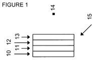
図1において、実装例が述べられている。10は、平面領域の照明を提供するための照明装置であり、照明は、三次元画像の生成をもたらすのに十分なコヒーレンスを有する。照明装置の例として、特許文献3において、広域ビデオ・ホログラムの場合における、図4に図示した一例が開示されている。10のような装置は、レンチキュラ・アレイやマイクロレンズ・アレイのように、小型であろう合焦システムに入射される光を発する冷陰極蛍光ランプや白色光発光ダイオードのような白色光源のアレイの形をとってもよい。あるいは、10に対する光源は、赤、緑、および青のレーザ、もしくは十分にコヒーレンスな光を放つ赤、緑、および青の発光ダイオードを含んでもよい。しかしながら、十分な空間コヒーレンスを有する非レーザ光源(例えば、発光ダイオード、OLED、冷陰極蛍光ランプ)は、レーザ光源より望ましい。レーザ光源は、ホログラフィック光源において、レーザ・スペックルを引き起こし、相対的に高価となり、ホログラフィック・ディスプレイの観察者の目や、ホログラフィック・ディスプレイ装置を組み立てる人々の目に損傷を与える可能性に関しての安全性の問題が有りうる、といった不利益を有する。 An example implementation is described in FIG. 10 is an illumination device for providing illumination of a planar area, the illumination having sufficient coherence to result in the generation of a three-dimensional image. As an example of the illumination device, Patent Document 3 discloses an example illustrated in FIG. 4 in the case of a wide-area video hologram. A device such as 10 is an array of white light sources such as cold cathode fluorescent lamps or white light emitting diodes that emit light that is incident on a compact focusing system, such as a lenticular array or a microlens array. It may take a shape. Alternatively, the light source for 10 may include red, green, and blue lasers, or red, green, and blue light emitting diodes that emit sufficiently coherent light. However, non-laser light sources (eg, light emitting diodes, OLEDs, cold cathode fluorescent lamps) with sufficient spatial coherence are more desirable than laser light sources. Laser light sources, in holographic light sources, cause laser speckle, are relatively expensive, and can damage the eyes of observers of holographic displays and those who assemble holographic display devices. There is a disadvantage that there may be a safety problem.
エレメント10〜13は、全体として厚さ数センチかそれよりも小さくできる。エレメント11は、カラー光源が用いられるのであれば必要ないが、エレメント12に向かって照射される赤、緑、及び青の光のような有色光の画素とするカラーフィルタのアレイを有しても良い。エレメント12は、透明基板における赤外線発光OLEDのアレイである。赤外線発光OLEDのアレイは、各赤外線発光OLEDが平行して光を発し、エレメント13の方向において、ユニークに対応づいた有色画素からの光と一致する。エレメント13は、OASLMである。OASLMに関しては、赤外線発光OLEDのアレイがライト・ビームを供給する(エレメント11によって放射された有色ビームは、リード・ビームである)。小型ホログラム生成器15を含む装置から離れたポイント14に位置する観察者は、15の方向において観察する際に三次元画像を観察しても良い。エレメント10、11、12、及び14は、物理的(例えば、実際に機械的であり、接触し、全体が一つで単一のオブジェクトであるようにできる構造のレイヤをそれぞれの形成する)になるように配置される。物理的接触(物理的接着)は、直接であっても良い。もしくは、薄く、隣接レイヤ間のフィルムに覆われた仲介レイヤが存在するのであれば、間接的であっても良い。物理的接触は、相互のアラインメントやレジストレーションを確実にするために小さな領域に限定されても良いし、広域やレイヤの全表面に広げられても良い。物理的接触は、小型ホログラム生成器15を形成するために光透過性を有する接着剤の利用によって、もしくは他の適した処理(以下の表題"製造プロセスの概要"のセクションを参照)によって、一緒に貼り付けられたレイヤによって成されても良い。
Elements 10-13 can be a few centimeters thick or less overall. The element 11 is not necessary if a color light source is used, but may have an array of color filters that are pixels of colored light such as red, green, and blue light that is emitted toward the
エレメント10は、ディスプレイの輝度を増加するための、1もしくは2のプリズム光学フィルムを含んでも良く、そのようなフィルムは、他にも知られているが、例えば米国特許第5056892号明細書や米国特許第5919551号明細書によって述べられている。エレメント10は、偏光光学エレメント、もしくは偏光光学エレメントの組を含んでいても良い。一つの例は、直線偏光子シートである。更なる例は、直線偏光状態を伝達し、直交する直線偏光状態を反射する反射偏光子であり、そのようなシートは他にも知られているが、例えば、米国特許第5828488号明細書にて述べられている。更なる例は、円偏光状態を伝達し、直交する円偏光状態を反射する反射偏光子であり、そのようなシートは他にも知られているが、例えば、米国特許第6181395号明細書にて述べられている。エレメント10は、レンチキュラ・アレイやマイクロレンズ・アレイのように小型にできる合焦システムを含んでいても良い。エレメント10は、バックライト技術の領域において知られたほかの光学エレメントを含んでも良い。
図4は、引用により本明細書に組み込まれる国際公開第2006/119920号パンフレットから得た、アレイにおける水平に並べられた円筒レンズの形で垂直合焦システム1104の3つの集約エレメント1101、1102、1103を示した先行技術の側面図である。照明ユニットの合焦エレメント1102を通り、観察者平面OPに達する、水平な線光源LS2にほぼ平行のビームが例示されている。図4に従って、多くの線光源LS1、LS2、LS3は上下に配置される。それぞれの光源は、垂直方向に十分に空間的にコヒーレントであり、水平方向には空間的にインコヒーレントである光を発する。光は、光変調器SLMの透過セルを通過する。光は、ホログラムとエンコードされる光変調器SLMのセルによって垂直方向のみに回折される。合焦エレメント1102は、観察者平面OPにて、いくらかの回折次数(1のみが実用的である)で光源LS2を画像化する。光源LS2によって発されたビームは、合焦システム1104の合焦エレメント1102のみを通ることが例示されている。図4において、3つのビームは、1番目の回折次数1105、ゼロ番目の次数1106、そして、マイナス1番目の次数1107を示す。単一の点光源とは対照的に、線光源は、たやすくより高い光度の製品を可能とする。すでに増大した効率や、再構成されるための3Dシーンの各部分に対する線光源の割り当てを有するいくつかのホログラフィック領域を用いることは、効率的な光度を向上させる。他の利点は、レーザの代わりに、例えば、シャッターの一部でも良いスロット隔壁の後方に位置付けられた多くの標準光源が十分にコヒーレント光を生成することである。
FIG. 4 shows three
<B.OLEDとOASLMとの組み合わせの2つの組の小型の組み合わせ>
さらに他の実施形態において、OLEDアレイとOASLMとの小型の組み合わせの2つの組の組み合わせは、連続で、かつ小型の方法で光の振幅と位相を変調するために用いられることができる。故に、振幅と位相からなる複素数は、画素毎の透過光においてエンコードされうる。
<B. Two sets of small combinations of OLED and OASLM combinations>
In yet another embodiment, two sets of small combinations of OLED arrays and OASLMs can be used to modulate the amplitude and phase of light in a continuous and compact manner. Therefore, a complex number composed of amplitude and phase can be encoded in the transmitted light for each pixel.
本実施形態は、IR−OLEDアレイとOASLMとの組の第1の小型の組み合わせとIR−OLEDアレイとOASLMとの組の第2の小型の組み合わせとを有する。第1の組は、透過光線の振幅を変調し、第2の組は透過光線の位相を変調する。あるいは、第1の組は、透過光線の位相を変調し、第2の組は、透過光線の振幅を変調する。IR−OLEDアレイとOASLMとの組の小型の組み合わせは、上記のセクションAにて述べられている。IR−OLEDアレイとOASLMとの組の小型の組み合わせは、可視光を透過し、赤外線を吸収する赤外線フィルタによって分けられる。 This embodiment has a first small combination of an IR-OLED array and OASLM set and a second small combination of an IR-OLED array and OASLM set. The first set modulates the amplitude of the transmitted light and the second set modulates the phase of the transmitted light. Alternatively, the first set modulates the phase of the transmitted light and the second set modulates the amplitude of the transmitted light. A small combination of the IR-OLED array and OASLM pair is described in section A above. The small combination of IR-OLED array and OASLM pair is separated by an infrared filter that transmits visible light and absorbs infrared light.
第1のステップにおいて、第1のIR−OLEDアレイは、第1のOASLMにおける振幅変調のためのパターンをライトする。第2のステップにおいて、第2のIR−OLEDアレイは、第2のOASLMにおける位相変調のためのパターンをライトする。赤外線フィルタは、IR−OLEDアレイとOASLMとの組の第1の小型の組み合わせから、IR−OLEDアレイとOASLMとの組の第2の小型の組み合わせへの赤外線の漏れを防ぐ。赤外線フィルタは、IR−OLEDアレイとOASLMとの組の第2の小型の組み合わせから、IR−OLEDアレイとOASLMとの組の第1の小型の組み合わせへの赤外線の漏れも防ぐ。しかしながら、赤外線フィルタは、IR−OLEDアレイとOASLMとの組の第2の小型の組み合わせにおけるリード・ビームとして用いるために、IR−OLEDアレイとOASLMとの組の第1の小型の組み合わせからの可視光を透過する。第2のOASLMによって透過された光は、その振幅とその位相において変調され、結果として、観察者は、装置によって照射された光を見る際に三次元画像を観測することが可能となる。 In the first step, the first IR-OLED array writes a pattern for amplitude modulation in the first OASLM. In the second step, the second IR-OLED array writes a pattern for phase modulation in the second OASLM. The infrared filter prevents infrared leakage from the first small combination of the IR-OLED array and OASLM set to the second small combination of the IR-OLED array and OASLM set. The infrared filter also prevents infrared leakage from the second small combination of the IR-OLED array and OASLM set to the first small combination of the IR-OLED array and OASLM set. However, the infrared filter is visible from the first small combination of the IR-OLED array and OASLM pair for use as a lead beam in the second small combination of the IR-OLED array and OASLM pair. Transmits light. The light transmitted by the second OASLM is modulated in its amplitude and phase so that the observer can observe a three-dimensional image when viewing the light emitted by the device.
位相や振幅の変調が複素数表現を促進することが当業者によって理解されるであろう。更に、OLEDディスプレイやOASLMは、どちらも高解像度を有することが可能である。故に、本実施形態は、三次元画像が観察者によって観察可能にホログラムを生成することに向くであろう。 It will be appreciated by those skilled in the art that phase and amplitude modulation facilitates complex representation. Furthermore, both OLED displays and OASLMs can have high resolution. Therefore, this embodiment will be suitable for generating a hologram so that a three-dimensional image can be observed by an observer.
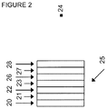
図2において、実施例が説明される。20は、平面領域の照明を提供するための照明装置であり、照明は三次元画像の生成をもたらすことができるために十分なコヒーレンスを有する。例は、広域ビデオ・ホログラムの場合として、特許文献3にて述べられている。20のような装置は、冷陰極蛍光ランプや白色光発光ダイオードのようなレンチキュラ・アレイやマイクロレンズ・アレイのように、小型にできる合焦システムにおいて入射される光を発する冷陰極蛍光ランプや白色光発光ダイオードのような白色光源のアレイの形をとってもよい。あるいは、20に対する光源は、赤、緑、および青のレーザ、もしくは十分にコヒーレンスな光を放つ赤、緑、および青の発光ダイオードを含んでいて良い。しかしながら、十分な空間コヒーレンスを有する非レーザ光源(例えば、発光ダイオード、OLED、冷陰極蛍光ランプ)は、レーザ光源より望ましい。レーザ光源は、ホログラフィック光源において、レーザ・スペックルを引き起こし、相対的に高価となり、ホログラフィック・ディスプレイ観察者の目や、ホログラフィック・ディスプレイ装置を組み立てる人々の目に損傷を与える可能性に関しての安全性の問題が有りうる、といった不利益を有する。 In FIG. 2, an example is described. 20 is an illuminating device for providing illumination of a planar area, and the illumination has sufficient coherence so that it can result in the generation of a three-dimensional image. An example is described in US Pat. An apparatus such as 20 is a cold cathode fluorescent lamp that emits incident light in a focusing system that can be miniaturized, such as a lenticular array or a microlens array such as a cold cathode fluorescent lamp or a white light emitting diode, or a white lamp. It may take the form of an array of white light sources such as light emitting diodes. Alternatively, the light source for 20 may include red, green, and blue lasers, or red, green, and blue light emitting diodes that emit sufficiently coherent light. However, non-laser light sources (eg, light emitting diodes, OLEDs, cold cathode fluorescent lamps) with sufficient spatial coherence are more desirable than laser light sources. Laser light sources cause laser speckle in holographic light sources, are relatively expensive, and can damage the eyes of holographic display observers and the people who assemble holographic display devices. There is a disadvantage that there may be a safety problem.
エレメント20−23、26−28は、全体として、厚さ数センチかそれよりも小さくできる。エレメント21は、カラー光源が用いられるのであれば必要ないが、エレメント22に向かって照射される赤、緑、および青の光のような有色光の画素とするカラーフィルタのアレイを有しても良い。エレメント22は、透明基板における赤外線発光OLEDのアレイである。赤外線発光OLEDのアレイは、各赤外線発光OLEDが平行して光を発し、エレメント23の方向において、ユニークに対応づいた有色画素からの光と一致する。エレメント23は、OASLMである。OASLMに関しては、赤外線発光OLEDのアレイがライト・ビームを供給する(エレメント21によって放射された有色ビームは、リード・ビームである)。エレメント28は、赤外線を遮るが、可視光を透過する赤外線フィルタであり、エレメント22からの赤外線が、エレメント27に影響を与えないようにする。エレメント27は、OASLMである。エレメント28は、透明基板における赤外線発光ダイオードのアレイである。赤外線発光OLEDのアレイは、各赤外線発光OLEDが平行して光を発し、エレメント27の方向において、ユニークに対応づいた有色画素からの光と一致する。OASLM27に関しては、赤外線発光OLED28のアレイがライト・ビームを供給する(エレメント26によって放射された有色ビームは、リード・ビームである)。透過光線に関しては、エレメント23が振幅を変調し、エレメント27が位相を変調する。あるいは、エレメント27が振幅を変調し、エレメント23が位相を変調する。透明基板28における赤外線発光ダイオードOLEDのアレイからの光は、エレメント26の方向に発せられるため、エレメント26は、エレメント28からの光をOASLM23にアドレス指定するのを妨げる赤外線を吸収しても良い。2つのOLEDアレイ22と28とが、十分に反対方向に光を放つ上記の構成は、2つのOASLM23と27とが、近接近にて設置されても良いことを保障する。OASLMを通った有色光のビームの伝搬が重ならない程度の接近によって成される近接近にOASLM23と27とがある場合に、OASLM23と27との近接近は、光学的損失や光ビームの発散から生じる画素クロストークの問題における減少を可能とする。エレメント27と28の順序は、図2とは反対でも良いが、これはOASLM23と27とを通る有色光のビーム間の高透過率や低クロストークの目的を達成するための最適形態であるというものではない。
The elements 20-23, 26-28 as a whole can be several centimeters thick or smaller. The
エレメント20は、ディスプレイの輝度を増加するための、1もしくは2のプリズム光学フィルムを含んでも良く、そのようなフィルムは、他にも知られているが、例えば米国特許第5056892号明細書や米国特許第5919551号明細書によって述べられている。エレメント20は、偏光光学エレメント、もしくは偏光光学エレメントの組を含んでいても良い。一つの例は、直線偏光子シートである。更なる例は、直線偏光状態を伝達し、直交する直線偏光状態を反射する反射偏光子であり、そのようなシートは他にも知られているが、例えば、米国特許第5828488号明細書にて述べられている。更なる例は、円偏光状態を伝達し、直交する円偏光状態を反射する反射偏光子であり、そのようなシートは他にも知られているが、例えば、米国特許第6181395号明細書にて述べられている。エレメント20は、レンチキュラ・アレイやマイクロレンズのように小型にして良い合焦システムを含んでいても良い。エレメント20は、バックライト技術の領域において知られた他の光学エレメントを含んでも良い。
小型ホログラム生成器25を含む装置から離れたポイント24に位置する観察者は、25の方向において観察の際に三次元画像を観察しても良い。エレメント20、21、22、23、26、27、及び28は、隣接エレメントが物理的(例えば、実際に機械的であり、接触し、全体が一つで単一のオブジェクトであるようにできる構造のレイヤをそれぞれの形成する)になるように配置される。物理的接触は、直接であっても良い。もしくは、薄く、隣接レイヤ間のフィルムに覆われた仲介レイヤが存在するのであれば、間接的であっても良い。物理的接触は、相互のアラインメントやレジストレーションを確実にするために小さな領域に限定されても良いし、広域やレイヤの全表面に広げられても良い。物理的接触は、小型ホログラム生成器15を形成するために光透過性を有する接着剤の利用によって、もしくは他の適した処理(以下の表題"製造プロセスの概要"のセクションを参照)によって、一緒に貼り付けられたレイヤによって成されても良い。
An observer located at a point 24 away from the apparatus including the
図2において、理想的な場合には、OLED22と28とのアレイは、十分に集束されている光を放つ。しかしながら、OLEDは、均等拡散(すなわち、完全に拡散した)分布の光のような、十分に集束されていない光を放つ可能性がある。OLEDの光の照射が高度に集束していない場合には、OLEDは、それらに対応づいたOASLMと出来る限り密接するように配置されても良い。この場合、OASLM表面上の強度入射は、入射角の余弦の二乗のように、おおよそ変化するであろうことが考えられる。45度や60度の光の入射は、それぞれ通常の入射光の半分、もしくは4分の1のみの強度をもたらすであろう。故に、OLEDが十分な間隔で、可視光の画素サイズと関連する十分な小ささで、OASLMと十分近くであれば、OLEDの照射分配は、均等拡散であると限定した場合であっても、形状効果は、空間的にOASLMを横断して生成された電位差における大きな変化をもたらすであろう。入射する赤外線強度は、OLED光が通常に入射するOASLM上の地点間において、ゼロになるであろうし、装置において達成されうる対照的な減少をもたらしても良い。しかし、この対照的な減少は、もし、デバイス構成を単純化するのであれば、許容できるであろう。
In FIG. 2, in an ideal case, an array of
図2において、理想的な場合には、OLED22及び28のアレイは、十分に集束されている光を発する。しかしながら、OLEDは、均等拡散(すなわち、完全に拡散した)分布の光のような、十分に集束されていない光が発せられる可能性がある。OLEDの光の放射が高度に集束していない場合には、OLEDの幾何学的な光分布は、引用により本明細書に組み込まれる米国特許第5153670号明細書にて述べられているようなBraggフィルタのホログラフィック光学エレメントの利用を通して、調整されても良い。Braggフィルタのホログラフィック光学エレメントは、平行にされるか、またはこのエレメントが無い場合よりも平行になった光をもたらす。Braggフィルタのホログラフィック光学エレメントの機能の例は、図8にて示している。図8において、80はOLEDアレイであり、81はBragg平面84のようなBragg平面を含むホログラフィック光学エレメント・Braggフィルタであり、82はOASLMである。OLEDアレイ80における単一のOLED83は、85のように概略的に示された分布で赤外線を発する。光線86は、OLEDアレイ80によって発せられ、ホログラフィック光学エレメント81にて散乱し、その後、おおよそ通常の入射におけるOASLM82に入射する、ことが示されている。このように、OASLM82に入射する赤外線の改善した視準が達成されても良い。
In FIG. 2, in the ideal case, the array of
図5において、更なる実施形態を開示する。57は、平面領域の照明を提供するための照明装置であり、当該照明は、三次元画像の生成できるため、十分なコヒーレンスを有する。特許文献3では、広域ビデオ・ホログラムの場合について、一例が開示されている。当該装置は、冷陰極蛍光ランプや白色光発光ダイオードのようなレンチキュラ・アレイやマイクロレンズ・アレイ50のように、小型合焦システムに入射される光を発する冷陰極蛍光ランプや白色光発光ダイオードのような白色光源のアレイの形式であってもよい。あるいは、57に対する光源は、赤、緑及び青のレーザ、又は十分にコヒーレントな光を発光する赤、緑及び青の発光ダイオードを含んでもよい。しかしながら、十分な空間コヒーレンスを有する非レーザ光源(例えば、発光ダイオード、OLED、冷陰極蛍光ランプ)は、レーザ光源より望ましい。レーザ光源は、ホログラフィック光源において、レーザ・スペックルを引き起こし、相対的に高価となり、ホログラフィック・ディスプレイ観察者の目や、ホログラフィック・ディスプレイ装置を組み当てる人々の目に損害を与える可能性に関しての安全性の問題が有りうる、といった不利益を有する。
In FIG. 5, a further embodiment is disclosed. 57 is an illuminating device for providing illumination of a planar area, and the illumination has sufficient coherence because it can generate a three-dimensional image. Patent Document 3 discloses an example of a wide-area video hologram. The apparatus is a cold cathode fluorescent lamp or white light emitting diode that emits light incident on a small focusing system, such as a lenticular array or
エレメント57は、ディスプレイの輝度を増加するための、1又は2のプリズム光学フィルムを含んでも良く、そのようなフィルムは、他にも知られているが、例えば米国特許第5056892号明細書や米国特許第5919551号明細書において開示されている。エレメント57は、偏光光学エレメント、もしくは偏光光学エレメントの組を含んでいても良い。一つの例は、線形偏光子シートである。更なる例は、線形偏光状態を透過させ、直交する線形偏光状態を反射する反射偏光子であり、そのようなシートは他にも知られているが、例えば、米国特許第5828488号明細書において開示されている。更なる例は、円偏光状態を透過させ、直交する円偏光状態を反射する反射偏光子であり、そのようなシートは他にも知られているが、例えば、米国特許第6181395号明細書において開示されている。エレメント57は、バックライト技術の領域において知られた他の光学エレメントを含んでも良い。
エレメント57、50−54は、全体として、厚さ数センチメートルかそれよりも小さくできる。エレメント51は、カラー光源が用いられるのであれば必要ないが、エレメント52に向かって発される赤、緑及び青の光のような有色光の画素とするカラーフィルタのアレイを有しても良い。エレメント52は、透明基板上の赤外線発光OLEDのアレイである。赤外線発光OLEDのアレイは、各有色画素に対し、赤外線発光OLEDの2つのタイプから成るユニークな組は、エレメント53の方向において光を平行に発し、対応する有色画素からの光と同期する。赤外線OLEDの第1のタイプは、第1の波長の赤外線を発する。赤外線OLEDの第2のタイプは、第1の波長とは異なる第2の波長の赤外線を発する。エレメント53はOASLMである。エレメント54もまたOASLMである。OASLMに関し、赤外線発光OLEDのアレイは、ライト・ビームを供給する。エレメント51によって発せられる有色ビームは、リード・ビームである。OASLM53は、OLEDアレイ52によって発された2つの赤外線波長のうちの第2の波長には無感応であり、OLEDアレイ52によって発された2つの赤外線波長のうちの第2の波長を透過させる。第1の赤外線波長に対するOASLM54の無感応が、必ずしも小型ホログラム生成器55の必要条件とはしないように、OASLM54は、OLEDアレイ52によって発された2つの赤外線波長のうちの第1の波長には無感応であり、もしくは、第1の赤外線波長の光は、OASLM53によってそれらの吸収、もしくは反射の少なくとも一方を通過し、続けて他の場所で吸収され、OASLM54に到達するのを妨げられる。もしくは、2つの異なった波長を発するOLEDの単一のタイプを用いることを可能としても良く、2つの異なる波長の相対強度は、OLEDを通過した電圧のようなパラメータに基づく。2つの異なる波長の発光は、時間的多重によって制御され得る。
透過光線に関しては、エレメント53が振幅を変調し、エレメント54が位相を変調する。あるいは、エレメント54が振幅を変調し、エレメント53が位相を変調する。異なる2つの波長の光を発するOLEDアレイ52における上記の構成によって、2つのOASLM53及び54を近接して配置することができる。OASLM53及び54を近接させることによって、光ビームの発散によって生じる光学的損失及び画素のクロストークの問題を軽減し得る。即ち、OASLM53及び54を近接させるにつれて、有色光のビームの、OASLMを介した重なり合わない伝搬に対する良好な近似を達成し得る。
For transmitted light,
小型ホログラム生成器55を含む装置から少し離れたポイント56に位置する観察者は、55の方向に観察する場合に、三次元画像を観察し得る。エレメント57、50、51、52、53及び54は、隣接エレメントが物理的(例えば、実際に機械的であり、接触し、全体が一つで単一のオブジェクトであるようにできる構造のレイヤをそれぞれの形成する)になるように配置される。物理的接触は、直接であっても良い。もしくは、薄く、隣接レイヤ間のフィルムに覆われた仲介レイヤが存在するのであれば、間接的であっても良い。物理的接触は、相互のアラインメントやレジストレーションを確実にするために小さな領域に限定されても良いし、広域やレイヤの全表面に広げられても良い。物理的接触は、小型ホログラム生成器15を形成するために光透過性を有する接着剤の利用によって、もしくは他の適した処理(以下の表題"製造プロセスの概要"のセクションを参照)によって、一緒に貼り付けられたレイヤによって成されても良い。
An observer located at a point 56 slightly away from the device containing the
OASLMが、典型的な構成にて振幅変調を行う場合、入射リード光学ビームは、ビームで直線偏光シートを通ることによって、直線に偏光されるであろう。振幅変調は、加えられた電場における液晶の循環によって制御され、電場は感光レイヤによって生成され、光の偏光状態に影響する。そのような装置において、OASLMに存在する光は、直線偏光シートを更に通され、OASLMを通る際に光の偏光状態において変化をもたらし、強度減縮を可能とする。 When the OASLM performs amplitude modulation in a typical configuration, the incident lead optical beam will be linearly polarized by passing the linear polarizing sheet with the beam. Amplitude modulation is controlled by the circulation of the liquid crystal in the applied electric field, which is generated by the photosensitive layer and affects the polarization state of the light. In such a device, the light present in the OASLM is further passed through a linear polarizing sheet, causing a change in the polarization state of the light as it passes through the OASLM, allowing intensity reduction.
OASLMが、典型的な構成にて位相変調を行う場合、すでに定義された直線偏光状態である場合を除いて、入射リード光学ビームは、ビームで直線偏光シートを通ることによって、直線に偏光されるであろう。位相変調は、加えられた電場の散布によって制御され、電場は感光レイヤによって生成され、光の位相状態に影響を与える。ネマチック相液晶を用いて導入された位相変調の一例において、光軸方向は、間隔を介して決められるが、複屈折は加えられた電圧の作用である。強誘電性液晶を用いて導入された位相の構成の一例において、複屈折は決められるが、光軸の方向は加えられた電圧によって制御される。他の方法を用いて導入された位相変調において、出力ビームは入力ビームに対応する位相差を有し、加えられた電圧の機能である。位相変調を実行可能な液晶セルの例は、正誘電異方性を有するネマチック液晶の非平行に配置された領域におけるフレドリックセルアレイがあり、引用により本明細書に組み込まれる米国特許第5973817号明細書にて述べられている。 When the OASLM performs phase modulation in a typical configuration, the incident lead optical beam is linearly polarized by passing through the linear polarizing sheet with the beam, unless it is in the linear polarization state defined previously. Will. Phase modulation is controlled by the application of an applied electric field, which is generated by the photosensitive layer and affects the phase state of the light. In one example of phase modulation introduced using nematic phase liquid crystals, the optical axis direction is determined via the spacing, but birefringence is the effect of the applied voltage. In one example of a phase configuration introduced using ferroelectric liquid crystals, birefringence is determined, but the direction of the optical axis is controlled by the applied voltage. In phase modulation introduced using other methods, the output beam has a phase difference corresponding to the input beam and is a function of the applied voltage. An example of a liquid crystal cell capable of performing phase modulation is a Fredric cell array in a non-parallel region of a nematic liquid crystal having positive dielectric anisotropy, which is incorporated herein by reference. US Pat. No. 5,973,817 It is stated in.
<C.EASLMと小型光源との小型の組み合わせ>
この実装は、EASLMと十分なコヒーレンスの小型光源との小型の組み合わせを提供し、その組み合わせは、適切な照明条件の下、三次元画像を生成することができる。
<C. Small combination of EASLM and small light source>
This implementation provides a small combination of an EASLM and a small light source with sufficient coherence, which combination can generate a three-dimensional image under appropriate lighting conditions.
この実装において、結像光学系を要件としないEASLMと小型光源との小型の組み合わせが、述べられている。この実装は、単一のもしくは複数の光源、焦点手段、電気的にアドレス指定された空間光変調器(EASLM)、及び空間ビーム分割エレメントの小型の組み合わせを提供し、その組み合わせは、適切な照明条件の下、三次元画像を生成することができる。 In this implementation, a small combination of EASLM and small light source that does not require an imaging optics is described. This implementation provides a compact combination of single or multiple light sources, focusing means, an electrically addressed spatial light modulator (EASLM), and a spatial beam splitting element, which combination is suitable for illumination Under the conditions, a three-dimensional image can be generated.
図11において、実装例が述べられている。110は、平面領域の照明を提供するための照明装置であり、照明は、三次元画像の生成をもたらすのに十分なコヒーレンスを有する。照明装置の例として、特許文献3において、広域ビデオ・ホログラムの場合における、図4に再現した一例が開示されている。110のような装置は、レンチキュラ・アレイやマイクロレンズ・アレイのように、小型にできる合焦システムにおいて入射される光を発する冷陰極蛍光ランプや白色光発光ダイオードのような白色光源のアレイの形をとってもよい。あるいは、110に対する光源は、赤、緑、および青のレーザ、もしくは十分にコヒーレンスな光を放つ赤、緑、および青の発光ダイオードを含んでいて良い。赤、緑、および青の発光ダイオードは、有機発光ダイオード(OLED)でも良い。しかしながら、十分な空間コヒーレンスを有する非レーザ光源(例えば、発光ダイオード、OLED、冷陰極蛍光ランプ)は、レーザ光源より望ましい。レーザ光源は、ホログラフィック光源において、レーザ・スペックルを引き起こし、相対的に高価となり、ホログラフィック・ディスプレイ観察者の目や、ホログラフィック・ディスプレイ装置を組み当てる人々の目に損害を与える可能性に関しての安全性の問題が有りうる、といった不利益を有する。 In FIG. 11, an implementation example is described. 110 is an illuminating device for providing illumination of a planar area, the illumination having sufficient coherence to result in the generation of a three-dimensional image. As an example of the illumination device, Patent Document 3 discloses an example reproduced in FIG. 4 in the case of a wide-area video hologram. A device such as 110 is in the form of an array of white light sources such as cold cathode fluorescent lamps or white light emitting diodes that emit incident light in a compact focusing system, such as a lenticular array or a microlens array. You may take Alternatively, the light source for 110 may include red, green, and blue lasers, or red, green, and blue light emitting diodes that emit sufficiently coherent light. The red, green and blue light emitting diodes may be organic light emitting diodes (OLEDs). However, non-laser light sources (eg, light emitting diodes, OLEDs, cold cathode fluorescent lamps) with sufficient spatial coherence are more desirable than laser light sources. Laser light sources, in holographic light sources, cause laser speckle, are relatively expensive, and can damage the eyes of holographic display observers and people wearing holographic display devices. There is a disadvantage that there may be a safety problem.
エレメント110は、厚さ数センチかそれよりも小さくできる。最適な実施形態において、エレメント110−113は、全体で厚さ3cmよりも小さく、十分なコヒーレンスの小型光源を提供することができる。エレメント111は、カラー光源が用いられるのであれば必要ないが、エレメント112に向かって照射される赤、緑、および青の光のような有色光の画素とするカラーフィルタのアレイを有しても良い。エレメント112は、EASLMである。エレメント113は、光学ビーム・スプリッタエレメントである。小型ホログラム生成器115を含む装置から離れたポイント114に位置する観察者は、115の方向における観察の際に三次元画像を見ても良い。
エレメント110は、ディスプレイの輝度を増加するための、1もしくは2のプリズム光学フィルムを含んでも良く、そのようなフィルムは、他にも知られているが、例えば米国特許第5056892号明細書や米国特許第5919551号明細書によって述べられている。エレメント20は、偏光光学エレメント、もしくは偏光光学エレメントの組を含んでいても良い。一つの例は、直線偏光子シートである。更なる例は、直線偏光状態を伝達し、直交する直線偏光状態を反射する反射偏光子であり、そのようなシートは他にも知られているが、例えば、米国特許第5828488号明細書にて述べられている。更なる例は、円偏光状態を伝達し、直交する円偏光状態を反射する反射偏光子であり、そのようなシートは他にも知られているが、例えば、米国特許第6181395号明細書にて述べられている。エレメント110は、バックライト技術の領域において知られた他の光学エレメントを含んでも良い。
EASLMは、セルのアレイにおいて各セルが電気的にアドレス指定されたSLMである。各セルは、透過する光の振幅を変調し、もしくは透過する光の位相を変調し、もしくは透過する光の振幅や位相の組み合わせを変調するといった、いくつかの方向において光の入射に影響を与える。EASLMの例は、引用により本明細書に組み込まれる米国特許第5973817号明細書にて与えられており、その例は、位相変調EASLMである。液晶EASLMNは、EASLMの例である。光磁気EASLMは、EASLMの他の例である。 An EASLM is an SLM in which each cell is electrically addressed in an array of cells. Each cell affects the incidence of light in several directions, such as modulating the amplitude of transmitted light, modulating the phase of transmitted light, or modulating the amplitude or phase combination of transmitted light . An example of an EASLM is given in US Pat. No. 5,973,817, which is incorporated herein by reference, an example of which is a phase modulated EASLM. The liquid crystal EASLMN is an example of an EASLM. A magneto-optical EASLM is another example of an EASLM.
エレメント110、111、112、及び113は、隣接エレメントが物理的(例えば、実際に機械的であり、接触し、全体が一つで単一のオブジェクトであるようにできる構造のレイヤをそれぞれの形成する)になるように配置される。物理的接触は、直接であっても良い。もしくは、薄く、隣接レイヤ間のフィルムに覆われた仲介レイヤが存在するのであれば、間接的であっても良い。物理的接触は、相互のアラインメントやレジストレーションを確実にするために小さな領域に限定されても良いし、広域やレイヤの全表面に広げられても良い。物理的接触は、小型ホログラム生成器115を形成するために光透過性を有する接着剤の利用によって、もしくは他の適した処理(以下の表題"製造プロセスの概要"のセクションを参照)によって、一緒に貼り付けられたレイヤによって成されても良い。
図4は、アレイにおける水平に並べられた円筒レンズの形で垂直合焦システム1104の3つの合焦エレメント1101、1102、1103を示した先行技術の側面図である。照明ユニットの合焦エレメント1102を通り、観察者平面OPに達する、水平な線光源LS2にほぼ平行のビームが例示されている。図4に従って、多くの線光源LS1、LS2、LS3は上下に配置される。それぞれの光源は、垂直方向に十分にコヒーレントであり、水平方向にはインコヒーレントである光を発する。光は、光変調器SLMの透過セルを通過する。光は、ホログラムとエンコードされる光変調器SLMのセルによって垂直方向のみに回折される。合焦エレメント1102は、観察者平面OPにて、いくらかの回折次数(1のみが実用的である)で光源LS2を画像化する。光源LS2によって発されたビームは、合焦システム1104の合焦エレメント1102のみを通ることが例示されている。図4において、3つのビームは、1番目の回折次数1105、ゼロ番目の次数1106、そして、マイナス1番目の次数1107を示す。単一の点光源とは対照的に、線光源は、より高い光強度を生成可能とする。すでに増大した効率や、再構成されるための3Dシーンの各部分に対する線光源の割り当てを有するいくつかのホログラフィック領域を用いることは、効率的な光度を向上させる。他の利点は、レーザの代わりに、例えば、シャッターの一部でも良いスロット隔壁の後方に位置付けられた多くの標準光源が十分にコヒーレント光を生成することである。
FIG. 4 is a prior art side view showing the three focusing
一般に、ホログラフィック・ディスプレイは、仮想観察者ウィンドウにおいて、波面を再構成する。波面は、もし存在していれば、実オブジェクトが生成したであろうものである。観察者は、彼の目が、いくつかの有効な仮想観察者ウィンドウ(VOW)のうちの一つの仮想観察者ウィンドウに位置する際に、再構成されたオブジェクトを見る。図6Aに示されているように、ホログラフィック・ディスプレイは、光源、レンズ、SLM、及び光学ビーム・スプリッタ、といったコンポーネントを含む。 In general, holographic displays reconstruct the wavefront in a virtual observer window. The wavefront, if present, is what the real object would have created. The observer sees the reconstructed object when his eye is located in one of the several valid virtual observer windows (VOWs). As shown in FIG. 6A, the holographic display includes components such as a light source, a lens, an SLM, and an optical beam splitter.
ホログラフィック画像を表示するSLMと小型光源との小型の組み合わせの創作を容易にするため、図6Aの単一の光源と単一のレンズは、図6Bに示されているように、単一の光源アレイと単一のレンズ・アレイ、もしくはレンチキュラ・アレイとにそれぞれ置き換えられても良い。図6Bにおいて、光源は、SLMを照射し、レンズは光源を観察者平面に投影する。SLMは、ホログラムをエンコードし、VOWにおいて所望の波面が再構成できるように、入射波面を変調する。光学ビーム・スプリッタ・エレメントは、例えば、一つの左目に対するVOWと一つの右目に対するVOWのように、いくつかのVOWを生成するために利用されても良い。 To facilitate the creation of a small combination of an SLM displaying a holographic image and a small light source, the single light source and single lens of FIG. 6A, as shown in FIG. A light source array and a single lens array or a lenticular array may be respectively replaced. In FIG. 6B, the light source illuminates the SLM and the lens projects the light source onto the viewer plane. The SLM encodes the hologram and modulates the incident wavefront so that the desired wavefront can be reconstructed in the VOW. The optical beam splitter element may be used to generate several VOWs, for example, a VOW for one left eye and a VOW for one right eye.
もし、光源アレイやレンズ・アレイ、もしくはレンチキュラ・アレイが用いられるのであれば、アレイからの光源は、光束が、VOWが一致するレンズ・アレイもしくは、レンチキュラ・アレイの全てを通るように配置されるべきである。 If a light source array, lens array, or lenticular array is used, the light source from the array is placed so that the light beam passes through all of the lens array or lenticular array with the matching VOW. Should.
図6Bの装置は、小型ホログラフィック・ディスプレイに用いることができる小型設計に役立つ。上記のホログラフィック・ディスプレイは、例えば携帯電話やPDAなどの携帯装置に利用されても良い。一般に、上記ホログラフィック・ディスプレイは、1インチもしくは数インチのオーダのスクリーン対角線を有する。ホログラフィック・サブディスプレイは、1cmのスクリーン対角線を有する。適切なコンポーネントは、詳細に以下で述べられる。 The device of FIG. 6B is useful for small designs that can be used in small holographic displays. The holographic display described above may be used in a mobile device such as a mobile phone or a PDA. In general, the holographic display has a screen diagonal on the order of one inch or several inches. The holographic sub-display has a 1 cm screen diagonal. Suitable components are described in detail below.
1)光源/光源アレイ
単純な場合において、固定単一光源を用いることができる。もし、観察者が動けば、観察者はトラッキングされ、ディスプレイは、観察者の新しい位置において観察可能な画像を生成するために調整されるであろう。ここでは、VOWのトラッキングが無い、もしくは、トラッキングがSLMの後方のビーム・ステアリング・エレメントを用いて実行されることとなる。
1) Light source / light source array In a simple case, a fixed single light source can be used. If the viewer moves, the viewer will be tracked and the display will be adjusted to produce an observable image at the viewer's new location. Here, there is no VOW tracking, or tracking will be performed using the beam steering element behind the SLM.
構造化可能な光源アレイは、バックライトによって照射された液晶ディスプレイ(LCD)によって達成されても良い。適切な画素のみが、点、もしくは線光源のアレイを生成するために透過状態に切り替えられる。これらの光源のアパーチャは、オブジェクトのホログラフィック再構成のための十分な空間コヒーレンスを保証するために、十分に小さくなければならない。点光源のアレイは、レンズの2Dアレイを含むレンズ・アレイと組み合わせて用いられても良い。線光源のアレイは、円筒状のレンズの平行アレイを含むレンチキュラ・アレイと組み合わせて用いられても良い。 A structured light source array may be achieved by a liquid crystal display (LCD) illuminated by a backlight. Only the appropriate pixels are switched to the transmissive state to produce an array of points or line sources. These light source apertures must be small enough to ensure sufficient spatial coherence for holographic reconstruction of the object. An array of point light sources may be used in combination with a lens array including a 2D array of lenses. The array of line light sources may be used in combination with a lenticular array that includes a parallel array of cylindrical lenses.
好適には、OLEDディスプレイは、光源アレイとして用いられる。自動発光装置のように、生成光のほとんどが、有色フィルタのようなエレメントによって、もしくは、完全な透過可能状態でない画素にて吸収されるLCDよりも、より小型で、よりエネルギー効率が良い。しかしながら、LCDは、OLEDディスプレイが、LCDディスプレイよりもエネルギー効率良く、光を供給する状況を許すようなときでさえ、OLEDディスプレイ以上の全体的なコスト面での利点を有する。OLEDディスプレイが、光源アレイとして用いられる際に、それらの画素のみが目の位置におけるVOWを生成するために必要となるように切り替えられる。OLEDディスプレイは、画素の2Dアレイもしくは線光源の1Dアレイを有しても良い。各点光源の照射領域、もしくは各線光源の幅は、オブジェクトのホログラフィック再構成のために十分な空間コヒーレンスを保証するために十分に小さくするべきである。さらに、点光源アレイは、好ましくは、レンズの2Dアレイを有するレンズ・アレイと組み合わせて用いられる。線光源アレイは、好ましくは、円筒状のレンズの平行アレイを有するレンチキュラ・アレイと組み合わせて用いられる。 Preferably, the OLED display is used as a light source array. Like automatic light-emitting devices, most of the generated light is smaller and more energy efficient than LCDs that are absorbed by elements such as colored filters or by pixels that are not fully transmissive. However, LCDs have an overall cost advantage over OLED displays, even when the OLED display is more energy efficient than the LCD display and allows the situation of supplying light. When an OLED display is used as a light source array, only those pixels are switched so that they are needed to generate a VOW at the eye position. The OLED display may have a 2D array of pixels or a 1D array of line light sources. The illumination area of each point source or the width of each line source should be small enough to ensure sufficient spatial coherence for holographic reconstruction of the object. Furthermore, the point source array is preferably used in combination with a lens array having a 2D array of lenses. The line source array is preferably used in combination with a lenticular array having a parallel array of cylindrical lenses.
2)合焦手段:単一レンズ、レンズ・アレイ、もしくはレンチキュラ・アレイ
合焦手段は、単一もしくは複数の光源を観察者平面へ結像させる。SLMが焦点手段に近接しているので、SLMにてエンコードされた情報のフーリエ変換は、観察者平面ないに存在する。合焦手段は、1もしくは複数の合焦エレメントを有する。SLMと合焦手段との位置は、入れ替えられても良い。
2) Focusing means: single lens, lens array, or lenticular array The focusing means forms an image of a single or multiple light sources on the observer plane. Since the SLM is close to the focusing means, the Fourier transform of the information encoded in the SLM exists in the observer plane. The focusing means has one or a plurality of focusing elements. The positions of the SLM and the focusing means may be interchanged.
EASLMと十分なコヒーレンスを有する小型光源との小型の組み合わせに対し、薄い合焦手段を有することは不可欠である。凸面を有する標準反射レンズはとても分厚い。代わりに、回折レンズ、もしくはホログラフィックレンズが用いられても良い。この回折レンズもしくは、ホログラフィックレンズは、単一レンズ、レンズ・アレイ、もしくはレンチキュラ・アレイの機能を有しても良い。上記構成要素は、Physical Optics Corporation, Torrance, CA, USAによって提供されている表面レリーフのホログラフィック製品を利用できる。代わりに、レンズ・アレイが用いられても良い。レンズ・アレイは、レンズの2Dアレイを含み、各レンズは光源アレイのうちの一つの光源に割り当てられている。他の代替案は、レンチキュラ・アレイが用いられても良い。レンチキュラ・アレイは、円筒状のレンズの1Dアレイを有し、各レンズは、光源アレイにおける対応光源を有する。上記のように、もし光源アレイや、レンズ・アレイもしくはレンチキュラ・アレイが用いられるのであれば、アレイ中の光源は、光束が、レンズ・アレイ中の全てのレンズ、もしくはVOW中の一致するレンチキュラ・アレイを通るように位置付けられるべきである。 For a small combination of EASLM and a small light source with sufficient coherence, it is essential to have a thin focusing means. Standard reflective lenses with convex surfaces are very thick. Instead, a diffractive lens or a holographic lens may be used. This diffractive lens or holographic lens may have the function of a single lens, a lens array, or a lenticular array. The above components may utilize surface relief holographic products provided by Physical Optics Corporation, Torrance, CA, USA. Alternatively, a lens array may be used. The lens array includes a 2D array of lenses, each lens being assigned to one light source of the light source array. Another alternative may be to use a lenticular array. The lenticular array has a 1D array of cylindrical lenses, each lens having a corresponding light source in the light source array. As described above, if a light source array, lens array, or lenticular array is used, the light source in the array will have a luminous flux that matches all the lenses in the lens array or the matching lenticular array in the VOW. Should be positioned through the array.
レンズ・アレイ、もしくはレンチキュラ・アレイのレンズを通った光は、複数の他のレンズと関連する或るレンズに対しインコヒーレントである。故に、SLMにてエンコードされたホログラムはサブホログラムから構成され、各サブホログラムは、一つのレンズと対応する。各レンズのアパーチャは、再構成されたオブジェクトの十分な解像度を保証するために、十分に大きくすべきである。例えば、米国特許出願公開第2006/0055994号明細書で述べるように、ホログラムのエンコード領域の典型的な大きさと同程度の大きさのアパーチャを有するレンズを用いても良い。これは、各レンズが1もしくは数ミリメータのオーダのアパーチャを有すべきことを意味している。 Light that passes through a lens array, or a lens of a lenticular array, is incoherent to one lens associated with a plurality of other lenses. Therefore, the hologram encoded by the SLM is composed of sub-holograms, and each sub-hologram corresponds to one lens. The aperture of each lens should be large enough to ensure sufficient resolution of the reconstructed object. For example, as described in U.S. Patent Application Publication No. 2006/0055994, a lens having an aperture that is approximately the same size as the typical size of the encoded region of the hologram may be used. This means that each lens should have an aperture on the order of one or several millimeters.
3)SLM
ホログラムはSLMでエンコードされる。通常、ホログラムのためのエンコーディングは、複素数の2Dアレイからなる。よって、理想的には、SLMは、SLMの各画素を通過するローカル・ライト・ビームの振幅と位相を変調できるであろう。しかしながら、典型的なSLMは振幅と位相とのいずれかを変調することはできるが、振幅と位相を独立に変調することはできない。
3) SLM
The hologram is encoded with SLM. Usually, the encoding for a hologram consists of a complex 2D array. Thus, ideally, the SLM could modulate the amplitude and phase of the local light beam that passes through each pixel of the SLM. However, a typical SLM can modulate either amplitude or phase, but cannot modulate amplitude and phase independently.
振幅変調SLMは、例えば、Burckhardtエンコーディングのような、迂回位相エンコーディングとの組み合わせで使用されてもよい。その難点は、一つの複素数をエンコードするために3画素が必要となることと、再構成されたオブジェクトが低輝度となることである。 Amplitude modulation SLM may be used in combination with detour phase encoding, eg, Burckhardt encoding. The difficulty is that 3 pixels are required to encode one complex number and the reconstructed object has low brightness.
位相変調SLMの再構成結果は、高輝度となる。例えば、一つの複素数をエンコードするために2画素を必要とする、所謂2相エンコーディングが使用されてもよい。 The reconstruction result of the phase modulation SLM is high brightness. For example, so-called two-phase encoding may be used that requires two pixels to encode one complex number.
EASLMは、輪郭のはっきりしたエッジの特性を有し、これにより回折パターンにおいて不要な高次の回折次数を招くことになるが、ソフト・アパーチャを利用することで、この問題を軽減、或いは、排除することができる。ソフト・アパーチャは、シャープな透過カットオフのないアパーチャである。ソフト・アパーチャの透過関数の例は、ガウシアン・プロファイルを有する。ガウシアン・プロファイルは、回折システムにおいて有利があることで知られている。その理由は、ガウシアン関数のフーリエ変換は、それ自体ガウシアン関数であるという数学的結果が存在するからである。よって、透過プロファイルにおいてシャープ・カット・オフを有するアパーチャを透過する場合と比べて、ラテラル・スケーリング・パラメータを除きビーム強度プロファイル関数は回折によっては変化しない。ガウシアン透過プロファイルのシートアレイが提供されてもよい。EASLMアパーチャと一直線上にこれらが提供される場合、ビーム透過プロファイルにおいてシャープ・カット・オフを有するシステムと比較して、高次の回折次数が欠落しているか、或いは、相当に軽減されたシステムが提供される。ガウシアン・フィルタ又は、ソフト・アパーチャ・フィルタは、高空間周波数から回折の影響を抑制する。ガウシアン・フィルタ又はアパーチャフィルタは、左目と右目の仮想的な観察者用のウィンドウ間のクロストークを最小化する。 EASLMs have well-defined edge characteristics, which can lead to unwanted higher order diffraction orders in the diffraction pattern, but this problem can be reduced or eliminated by using a soft aperture. can do. A soft aperture is an aperture without a sharp transmission cut-off. An example of a soft aperture transmission function has a Gaussian profile. Gaussian profiles are known to be advantageous in diffractive systems. This is because there exists a mathematical result that the Fourier transform of the Gaussian function is itself a Gaussian function. Therefore, the beam intensity profile function is not changed by diffraction except for the lateral scaling parameter, as compared with the case of transmitting through an aperture having a sharp cutoff in the transmission profile. A sheet array of Gaussian transmission profiles may be provided. When these are provided in line with the EASLM aperture, systems with missing or significantly reduced higher order diffraction orders compared to systems with sharp cut-offs in the beam transmission profile Provided. A Gaussian filter or a soft aperture filter suppresses the influence of diffraction from a high spatial frequency. Gaussian filters or aperture filters minimize crosstalk between the left and right eye virtual observer windows.
4)ビーム・スプリッタ・エレメント
VOWは、SLMにおいてエンコードされる情報のフーリエ変換の一つの周期的インターバルに限定される。現在利用可能な解像度が最大のSLMによれば、VOWのサイズは、10mmのオーダである。ある状況では、トラッキング無しのホログラフィック表示のアプリケーションでは、これは小さすぎるかも知れない。この問題に対する一つの解決策は、VOWを空間的に多重化することであり、2つ以上VOWが生成される。空間多重化を行う場合、VOWはSLMの異なる位置から同時に生成される。これは、ビーム・スプリッタにより実現されてもよい。例えば、SLMのある画素グループは、VOW1の情報によりエンコードされ、他のグループはVOW2の情報によりエンコードされる。ビーム・スプリッタは、VOW1とVOW2とが観察面において並列になるように、光をこれらの2つのグループから分離する。より大きなVOWは、VOW1とVOW2とをシームレスにタイル化することで生成されてもよい。多重化はまた、左目と右目のVOWを生成するために利用されてもよい。その場合、シームレスな並列化は必要とされず、左目用の一つまたはいくつかのVOWと、右目用の一つまたはいくつかのVOWとの間でギャップが生じてもよい。ここで、あるVOWの高次の回折次数が他のVOWの高次の回折次数とオーバラップしないように注意する必要がある。
4) Beam splitter element VOW is limited to one periodic interval of the Fourier transform of the information encoded in the SLM. According to the SLM with the highest resolution currently available, the VOW size is on the order of 10 mm. In some situations, this may be too small for holographic display applications without tracking. One solution to this problem is to spatially multiplex VOWs, generating more than one VOW. When performing spatial multiplexing, VOWs are generated simultaneously from different locations on the SLM. This may be realized by a beam splitter. For example, a pixel group with an SLM is encoded with VOW1 information, and other groups are encoded with VOW2 information. The beam splitter separates light from these two groups so that VOW1 and VOW2 are parallel in the viewing plane. A larger VOW may be generated by seamlessly tiling VOW1 and VOW2. Multiplexing may also be used to generate left eye and right eye VOWs. In that case, seamless parallelization is not required and a gap may occur between one or several VOWs for the left eye and one or several VOWs for the right eye. Here, care must be taken so that the higher order diffraction orders of one VOW do not overlap with the higher order diffraction orders of other VOWs.
ビーム・スプリッタ・エレメントの簡単な例は、引用により本明細書に組み込まれるところの特許文献4に記載されるように、縞の間が透明領域となっている黒い縞模様からなる視差バリアである。更なる例は、特許文献4に記載されているように、レンチキュラ・シートである。ビーム・スプリッタ・エレメントの更なる例は、レンズ・アレイとプリズム・マスクである。小型ホログラフィック・ディスプレイでは、約10cm離れた2つの目を有する典型的な観察者としては満足できないが、10mmという典型的な仮想的な観察者用のウィンドウサイズは、片目だけだと十分に大きいので、典型的にはビーム・スプリッタ・エレメントの存在が期待されるであろう。しかしながら、空間多重化の代わりに時間多重化を利用してもよい。空間多重化を行わない場合、ビーム・スプリッタ・エレメントを利用する必要はない。 A simple example of a beam splitter element is a parallax barrier consisting of black stripes with transparent areas between the stripes, as described in US Pat. . A further example is a lenticular sheet as described in US Pat. Further examples of beam splitter elements are lens arrays and prism masks. Small holographic displays are not satisfactory for a typical observer with two eyes about 10 cm apart, but the typical virtual observer window size of 10 mm is large enough with only one eye Thus, typically the presence of a beam splitter element would be expected. However, time multiplexing may be used instead of spatial multiplexing. If no spatial multiplexing is performed, it is not necessary to use a beam splitter element.
空間多重化は、カラー・ホログラフィック再構成のために利用されてもよい。空間カラー多重化のために、赤、緑、青の色成分のそれぞれ独立した画素グループが存在する。これらのグループはSLM上で空間的に分離されており、赤色光、緑色光、青色光で同時に照射される。各グループは、オブジェクトの各色成分について計算されたホログラムでエンコードされる。各グループは、ホログラフィック・オブジェクト再構成の色成分を再構成する。 Spatial multiplexing may be utilized for color holographic reconstruction. For spatial color multiplexing, there are independent pixel groups for red, green and blue color components. These groups are spatially separated on the SLM and are illuminated simultaneously with red light, green light and blue light. Each group is encoded with a hologram calculated for each color component of the object. Each group reconstructs the color components of the holographic object reconstruction.
5)時間多重化
時間多重化を行う場合、VOWはSLMの同一位置から連続的に生成される。これは、光源の位置を変更し、それに同期して再エンコーディングをすることによって実現されてもよい。光源位置の変更は、観察面においてVOWがシームレスに並列化されるように行われなければならない。時間多重化が十分に高速な場合、すなわち全サイクルについて25Hzより大きい場合、人の目には連続的な拡張VOWが映るであろう。
5) Time multiplexing When time multiplexing is performed, VOWs are continuously generated from the same position of the SLM. This may be achieved by changing the position of the light source and re-encoding in sync with it. The light source position must be changed so that the VOWs are seamlessly parallelized on the observation surface. If time multiplexing is fast enough, i.e. greater than 25 Hz for the entire cycle, the human eye will see a continuous extended VOW.
多重化は、左目と右目のVOWの生成のために利用されてもよい。その場合、シームレスな並列化は必要なく、左目用の一つ又はいくつかのVOWと、右目用の一つ又はいくつかのVOWとの間にギャップがあってもよい。この多重化は空間的であっても、時間的であってもよい。 Multiplexing may be utilized for the generation of left eye and right eye VOWs. In that case, seamless parallelization is not required and there may be a gap between one or several VOWs for the left eye and one or several VOWs for the right eye. This multiplexing may be spatial or temporal.
空間多重化と時間多重化とは組み合わされてもよい。例えば、片目用の拡張VOWを生成するために、3つのVOWが空間的に多重化される。この拡張VOWは、左目用の拡張VOWと右目用の拡張VOWとを生成するために時間多重化される。 Spatial multiplexing and time multiplexing may be combined. For example, in order to generate an extended VOW for one eye, three VOWs are spatially multiplexed. This extended VOW is time-multiplexed to generate an extended VOW for the left eye and an extended VOW for the right eye.
あるVOWと他のVOWとの高次の回折次数はオーバラップしないように気を付ける必要がある。 Care must be taken so that the higher diffraction orders of one VOW and the other VOW do not overlap.
VOWの拡張のための多重化は、観察者の動作に応じて、視差が連続的に変化する拡張VOWを提供するので、好ましくはSLMの再エンコーディングと共に利用される。単純化のため、再エンコーディング無しの多重化は、拡張VOWの異なる部分において反復コンテンツを提供するであろう。 Multiplexing for VOW extension is preferably used in conjunction with SLM re-encoding, as it provides an extended VOW whose parallax varies continuously according to observer behavior. For simplicity, multiplexing without re-encoding will provide repetitive content in different parts of the extended VOW.
時間多重化はまた、カラー・ホログラフィック再構成の生成のために利用されてもよい。時間多重化のために、3つの色成分のホログラムは連続的にSLM上でエンコードされる。3つの光源は、SLM上での再エンコーディングと同期して切り替えられる。全サイクルが十分に高速に反復される場合、すなわち25Hzより大きい場合、人の目には、連続的なカラー再構成として映るであろう。 Time multiplexing may also be utilized for the generation of color holographic reconstructions. Due to time multiplexing, the three color component holograms are sequentially encoded on the SLM. The three light sources are switched in synchronism with the re-encoding on the SLM. If the entire cycle is repeated fast enough, ie greater than 25 Hz, it will appear to the human eye as a continuous color reconstruction.
6)不要な高次の回折次数の扱い
もし、より大きなVOWが、小さなVOWをタイル状に並べることにより生成されるとすると、あるVOWの高次の回折次数により、この問題に対処する手だてを講じない限り、やっかいなクロストークが他のVOWにもたらされるかも知れない。例えば、もし各VOWが、SLMでエンコードされる情報のフーリエ変換のゼロ次の回折次数に位置する場合、あるVOWの一次回折次数は、隣接するVOWとオーバラップするかもしれない。このオーバラップは、やっかいな背景像をもたらすかも知れない。これは、不要な画像の強度が所望の画像の強度の約5%を超えた場合に顕著になるかもしれない。その場合、高次の回折次数を相殺するか、抑制することが望ましい。
6) Handling unwanted higher-order diffraction orders If a larger VOW is generated by tiling small VOWs, a higher-order diffraction order for a VOW can help address this problem. Unless you do it, troublesome crosstalk may be brought to other VOWs. For example, if each VOW is located in the zero order diffraction order of the Fourier transform of the information encoded in the SLM, the first order diffraction order of a VOW may overlap with an adjacent VOW. This overlap may result in a nasty background image. This may become noticeable when the intensity of the unwanted image exceeds about 5% of the desired image intensity. In that case, it is desirable to cancel or suppress higher-order diffraction orders.
もし、SLMが照射される角度が一定の場合、固定的な角度フィルタを利用することができる。これは、もし、ホログラフィック表示がトラッキングを行わないか、或いは、ビーム・ステアリング・エレメントのようなビーム・スプリッタ・エレメントが、SLMの後に位置するような場合である。固定的な角度フィルタは、Braggフィルタや、Fabry Perot Etalonであってもよい。 If the angle at which the SLM is irradiated is constant, a fixed angle filter can be used. This is the case if the holographic display does not track or a beam splitter element such as a beam steering element is located after the SLM. The fixed angle filter may be a Bragg filter or a Fabry Perot Etalon.
SLMは、不要な回折次数を含む幾何学的な光強度分散をもたらす場合、その幾何学的光強度分散は、米国特許第5153670号明細書に記載されるようなBraggフィルタ・ホログラフィック光学エレメントの利用により修正できるかも知れない。Braggフィルタ・ホログラフィック光学エレメントは、このエレメントがない場合の光強度分散とは異なる光強度分散をもたらす。Braggフィルタ・ホログラフィック光学エレメントの一例は、図7に示す通りである。図7において、70はSLMである。71は、Bragg平面74のようなBragg平面を含むBraggフィルタ・ホログラフィック光学エレメントである。SLM70内の単一セル73は、75で図示するような回折光の強度分散に貢献する。光線76は、SLM70によって回折されるものとして示されており、ホログラフィック光学エレメント71において散乱し、その後、70と71の間での本来の伝搬方向とは異なる方向に伝搬していく。もし、70と71との間での光線76の伝搬方向が、不要な一次回折光に対応する場合、Braggフィルタ71がこの光の行く先を異なる方向へ変更することに成功するのは明らかであり、70のおよそ法線方向に通常は位置する観察者を煩わせる不要な光学的副作用を助長することはないであろう。
If the SLM provides geometric light intensity dispersion that includes unwanted diffraction orders, the geometric light intensity dispersion is that of a Bragg filter holographic optical element as described in US Pat. No. 5,153,670. It may be corrected by use. Bragg filter holographic optical elements provide a light intensity dispersion that is different from the light intensity dispersion in the absence of this element. An example of a Bragg filter holographic optical element is as shown in FIG. In FIG. 7,
回折次数の抑制のための調整可能なFabry Perot Etalonは、独国特許出願公開第10 2006 030 503号明細書に開示されている。開示されているのは、部分的に反射膜によりコーティングされている、2つのコプラーナ・ガラスシートの間のLCレイヤである。当該反射膜における光線の反射において、光線は部分的に反射し、部分的に透過する。標準的なFabry Perot Etalonにあるように、透過光線は干渉し合い、光線間の位相の違いにより、干渉が建設的なものとなるか、或いは、相殺的なものとなるかが決まる。所望の波長において、干渉、即ち透過が、光線の入射角度に応じて変化する。所望の光伝搬方向について、LCの屈折率の変更により干渉を調整できる。屈折率は、LCレイヤを交差するように加えられる電場によって制御される。よって、角度透過特性を調整することができ、回折次数を透過率、或いは反射率について、Fabry Perot Etalonの全体的な制限内で必要に応じて選択することができる。例えば、もしFabry Perot Etalonがゼロ次の最適な透過率及び一次の最適な反射率を有するように構成された場合、2次或いはより高次の不要な透過が依然として残るかもしれない。この装置は、Fabry Perot Etalonの全体的な制限内で、必要に応じて、透過、或いは、反射される特定の回折次数の固定的な、或いは、連続的な選択を促進する。
A tunable Fabry Perot Etalon for suppression of diffraction orders is disclosed in
空間フィルタは、回折次数を選択するために利用されてもよい。これらの空間フィルタは、SLMとVOWとの間に配置されてもよく、透明領域と不透明領域とを有する。これらの空間フィルタは、所望の回折次数を透過する一方で、不要な回折次数をブロックするために利用されてもよい。これらの空間フィルタは、固定的なものであってもよいし、設定変更が可能なものであってもよい。例えば、SLMとVOWとの間に設置されるEASLMは、設定変更が可能な空間フィルタとして動作してもよい。 Spatial filters may be utilized to select the diffraction order. These spatial filters may be disposed between the SLM and the VOW and have a transparent area and an opaque area. These spatial filters may be utilized to block unwanted diffraction orders while transmitting the desired diffraction orders. These spatial filters may be fixed or changeable in settings. For example, an EASLM installed between the SLM and the VOW may operate as a spatial filter whose settings can be changed.
7)視線追跡(Eye Tracking)
EASLMと視線追跡と十分に整合する小型の光源とのコンパクトな組み合わせでは、目位置検出器により観察者の目の位置を検出してもよい。一つ以上のVOWは、観察者が再構成されたオブジェクトをVOWを介して見ることができるようにするために、自動的に目の位置に配置される。
7) Eye Tracking
In a compact combination of an EASLM and a small light source that is sufficiently aligned with eye tracking, the eye position of the observer may be detected by an eye position detector. One or more VOWs are automatically placed at the eye position to allow the observer to see the reconstructed object through the VOW.
しかしながら、追跡は常に実用的であるわけではなく、特に携帯型装置、或いは、ハンドヘルド機器の場合にそれが当てはまる。というのも、付加的な装置の要求に基づく制約や、実行のための所要電力が存在するからである。追跡を行わなければ、観察者は手動でディスプレイの位置を調整しなければならない。好適な実施形態において、小型ディスプレイは、PDAや携帯電話に組み込まれているような手持ち型のディスプレイであるので、これは、直ちに実行される。PDAや携帯電話のユーザは、ディスプレイに直交する方向からディスプレイを見る傾向があるので、VOWを目に対して調整するための追加的な労力はそれほど必要ない。例えば、引用により本明細書に組み込まれるところの国際公開第01/96941号パンフレットに記載されるように、ハンドヘルド機器のユーザは、最適な観察条件を達成するように、装置を手で正しい方向に自動的に向ける傾向があることは知られている。よって、そのような装置ではユーザの視線追跡は必要なく、例えば、走査ミラーのような複雑で小さくもない追跡用の光学エレメントも不要である。しかし、もし、装置に対する追加要件及び電力が、過剰な負担を装置に与えるものでなければ、視線追跡がそのような装置において実施されてもよい。 However, tracking is not always practical, especially in the case of portable devices or handheld devices. This is because there are constraints based on the requirements of additional devices and the power requirements for execution. Without tracking, the observer must manually adjust the position of the display. In a preferred embodiment, this is done immediately because the small display is a handheld display such as that incorporated in a PDA or mobile phone. PDA and mobile phone users tend to see the display from a direction orthogonal to the display, so that little additional effort is needed to adjust the VOW to the eye. For example, as described in WO 01/96941, which is incorporated herein by reference, a user of a handheld device can manually position the device in the right direction to achieve optimal viewing conditions. It is known that there is a tendency to turn automatically. Therefore, such a device does not require tracking of the user's line of sight, and does not require a complicated and small tracking optical element such as a scanning mirror. However, line of sight tracking may be implemented in such a device if the additional requirements and power on the device do not place an excessive burden on the device.
追跡を行わない場合、EASLMと、十分コヒーレントな小型光源とのコンパクトな組み合わせでは、ディスプレイの調整を単純化するために、VOWは十分に大きなものであることが必要とされる。望ましくは、VOWサイズは、人間の目の大きさの数倍であるべきである。これは、ピッチの小さなSLMを利用した単一の大きなVOWか、ピッチの大きなSLMを利用した小型のVOWをいくつかタイル状に並べたもの、のいずれかにより実現できる。 Without tracking, a compact combination of EASLM and a small enough light source that is sufficiently coherent requires the VOW to be large enough to simplify display adjustments. Desirably, the VOW size should be several times the size of the human eye. This can be realized by either a single large VOW using an SLM with a small pitch, or several small VOWs using a SLM with a large pitch arranged in a tile.
VOWの位置は、光源アレイにおける光源の位置により決定される。目位置検出器は、目の位置を検出し、VOWを該目の位置に合わせるために、光源の位置を設定する。この種の追跡は、米国特許出願公開第2006/055994号明細書及び特許文献3に記述されている。 The position of the VOW is determined by the position of the light source in the light source array. The eye position detector detects the position of the eye and sets the position of the light source in order to adjust the VOW to the position of the eye. This type of tracking is described in US 2006/055944 and US Pat.
また、光源が固定位置にある場合は、VOWを移動してもよい。光源トラッキングでは、光源からの光の入射角度の変動に対して比較的鈍感なSLMが必要となる。もし、光源を移動してVOW位置を移動させようとしても、小型光源とSLMとの小型の組み合わせでは、そのような構成が示唆する当該小型の組み合わせ内での光伝搬条件からずれるために、その達成が困難となる。そのような場合、ディスプレイにおいて一定の光路を持たせることが有利である。 When the light source is at a fixed position, the VOW may be moved. Light source tracking requires an SLM that is relatively insensitive to fluctuations in the incident angle of light from the light source. If the VOW position is moved by moving the light source, the small combination of the small light source and the SLM deviates from the light propagation conditions in the small combination suggested by such a configuration. It becomes difficult to achieve. In such a case, it is advantageous to have a constant optical path in the display.
これらの特性を提供することができるビーム・ステアリング・エレメントは、図20及び21に示すようになる。このビーム・ステアリング・エレメントは、ディスプレイの出力において、光束の角度を変化させる。それは、xトラッキング及びyトラッキングについて制御可能なプリズムと、zトラッキングについて制御可能なレンズの光学特性を有していてもよい。例えば、図20及び図21のいずれかのビーム・ステアリング・エレメント、或いはその両方は、単一装置において使用されてもよい。ビーム・ステアリング・エレメントは、制御可能な回折エレメント、或いは、制御可能な屈折エレメントである。制御可能な屈折エレメントは、等方性の線形電気双極子磁化率テンソル(isotropic linear electric dipole susceptibility tensor)を用いたマトリックスに埋め込まれた液晶が充填されたキャビティのアレイを有していてもよい。キャビティは、プリズムやレンズの形状を有する。電場を加えることにより、液晶の実効屈折率が制御されるので、ビーム操作が促進される。電場は、エレメントを交差して変化するビーム・ステアリング特性を作り出すために、エレメントを交差して変化してもよい。電場は、図2に示す透明電極間にかけられる。液晶は一軸屈折特性を有し、光軸に直交する屈折率が、母材(host material)、或いは、"マトリックス"の屈折率と等しくなるように選択されてもよい。他の構成は、当業者には自明であろう。母材は、等方性の屈折率を有する。もし液晶の光軸が、適切な電場をかけることにより図20に示すz方向に沿っている場合、そのPoyntingベクトルに垂直な屈折率の変動もないため、z方向に沿って伝搬する平面波はビーム・ステアリング・エレメントを通過する際に屈折することがない。しかしながら、もし、液晶の光軸がz方向に対して直交するように電場がエレメントを交差してかけられる場合、システムが提供可能な、偏光方向に沿った考えられる最大の屈折率の変動を経験するために、光軸に平行に偏光されたz方向に沿って伝搬する平面波は、ビーム・ステアリング・エレメントを通過する際に最大限の屈折をするであろう。屈折度は、母材を交差する適切な電場を選択することで、これらの2つの極端なケースの間で調整可能であろう。 A beam steering element that can provide these characteristics is as shown in FIGS. This beam steering element changes the angle of the luminous flux at the output of the display. It may have optical properties of a prism controllable for x-tracking and y-tracking and a lens controllable for z-tracking. For example, either of the beam steering elements of FIGS. 20 and 21 or both may be used in a single device. The beam steering element is a controllable diffractive element or a controllable refractive element. The controllable refractive element may have an array of cavities filled with liquid crystal embedded in a matrix using an isotropic linear electric dipole susceptibility tensor. The cavity has a prism or lens shape. By applying an electric field, the effective refractive index of the liquid crystal is controlled, which facilitates beam operation. The electric field may vary across the elements to create beam steering characteristics that vary across the elements. An electric field is applied between the transparent electrodes shown in FIG. The liquid crystal has uniaxial refractive properties and may be selected such that the refractive index orthogonal to the optical axis is equal to the refractive index of the host material or “matrix”. Other configurations will be apparent to those skilled in the art. The base material has an isotropic refractive index. If the optical axis of the liquid crystal is along the z direction shown in FIG. 20 by applying an appropriate electric field, there is no refractive index variation perpendicular to the Poynting vector, so that the plane wave propagating along the z direction is a beam. -No refraction when passing through the steering element. However, if the electric field is applied across the element so that the optical axis of the liquid crystal is orthogonal to the z direction, the system will experience the largest possible refractive index variation along the polarization direction that can be provided. To do so, a plane wave propagating along the z-direction, which is polarized parallel to the optical axis, will be refracted as much as it passes through the beam steering element. The index of refraction will be adjustable between these two extreme cases by selecting the appropriate electric field across the matrix.
ビーム操作は、キャビティがレンズ形状ではなくプリズム形状を有する場合に達成されるかも知れない。ビーム操作のための適切なプリズム形状は、図21に示される。もし液晶の光軸が、適切な電場をかけることにより図21に示すz方向に沿う場合、z方向に沿って伝搬する平面波は、ビーム・ステアリング・エレメントを通過する際に屈折しない。これは、その偏光方向において屈折率の変動が生じないためである。しかしながら、液晶の光軸をz方向と直交させるために電極と交差して電場がかけられると、光軸に平行に偏光されたz方向に伝搬する平面波は、ビーム・ステアリング・エレメントを通過するときに最大限に屈折する。これは、システムが提供可能なPoyntingベクトルに垂直な考えられる最大の屈折率の変動を経験するためである。屈折度は、母材を交差する適切な電場を選択することで、これらの2つの極端なケースの間で調整可能であろう。 Beam manipulation may be achieved when the cavity has a prism shape rather than a lens shape. A suitable prism shape for beam manipulation is shown in FIG. If the optical axis of the liquid crystal is along the z direction shown in FIG. 21 by applying an appropriate electric field, the plane wave propagating along the z direction will not be refracted as it passes through the beam steering element. This is because the refractive index does not vary in the polarization direction. However, when an electric field is applied across the electrode to make the optical axis of the liquid crystal perpendicular to the z-direction, plane waves propagating in the z-direction that are polarized parallel to the optical axis pass through the beam steering element. Refract to the maximum. This is because the system experiences the largest possible refractive index variation perpendicular to the Poynting vector that can be provided. The index of refraction will be adjustable between these two extreme cases by selecting the appropriate electric field across the matrix.
8)例
EASLMと十分にコヒーレントな小型光源との小型の組み合わせについて、例を説明する。当該組み合わせにより、適切な露光条件下において3次元画像を生成することが可能となり、PDAや携帯電話に搭載されてもよい。EASLMの小型の組み合わせ及び十分にコヒーレントな小型光源は、図12に示すように、光源アレイ、EASLM及びレンズ・アレイとしてOLEDディスプレイを有する。
8) Example An example of a small combination of an EASLM and a sufficiently coherent small light source will be described. This combination makes it possible to generate a three-dimensional image under appropriate exposure conditions and may be mounted on a PDA or mobile phone. A small combination of EASLMs and a sufficiently coherent compact light source has an OLED display as a light source array, an EASLM, and a lens array, as shown in FIG.
VOW(図12ではOWで示される)の要求される位置に応じて、OLEDディスプレイの特定画素が駆動される。これらの画素は、EASLMを照射し、レンズ・アレイにより観察面で映像を構成する。OLEDディスプレイにおいて、レンズ・アレイのレンズ毎にすくなくとも一画素が駆動される。図面において与えられる寸法では、画素ピッチが20μmの場合、VOWは水平増分が400μmでトラッキングできる。このトラッキングは準連続性を有している。 Depending on the required position of the VOW (shown as OW in FIG. 12), a particular pixel of the OLED display is driven. These pixels irradiate EASLM and compose an image on the observation surface by the lens array. In an OLED display, at least one pixel is driven for each lens in the lens array. For the dimensions given in the drawing, for a pixel pitch of 20 μm, the VOW can be tracked with a horizontal increment of 400 μm. This tracking is quasi-continuous.
OLED画素は、部分的にのみ空間コヒーレントな光源である。部分的にコヒーレントなため、オブジェクト点の再構成にはスミアが存在してしまう。図面において与えられる寸法では、ディスプレイから100mmの距離を有するオブジェクト点は、もし画素幅が20μmであれば、100μmの水平スミアを有して再構成される。これは、ヒューマン・ビジョン・システムの解像度としては十分である。 OLED pixels are only partially spatially coherent light sources. Because it is partially coherent, there will be smear in the reconstruction of object points. For the dimensions given in the drawing, an object point having a distance of 100 mm from the display is reconstructed with a horizontal smear of 100 μm if the pixel width is 20 μm. This is sufficient as the resolution of the human vision system.
レンズ・アレイの異なるレンズを通過する光同士には、十分な相互コヒーレンスはない。コヒーレンス要求は、レンズ・アレイの各単一レンズに限定されている。よって、再構成されたオブジェクト点の解像度は、レンズ・アレイのピッチにより決定される。典型的なレンズピッチは、ヒューマン・ビジョン・システムの解像度として十分なものを保証するために、1mmのオーダとなろう。もしOLEDピッチが20μmであれば、このことは、レンズピッチとOLEDピッチとの比率が50:1であることを意味する。もし、単一OLEDのみがレンズごとに発光する場合、このことは、502=2500OLED毎に一つだけのOLEDが発光することを意味する。よって、ディスプレイは、低電力ディスプレイとなるであろう。ここでのホログラフィック・ディスプレイと、従来のOLEDとの相違は、前者が光を観察者の目に集中させる一方で、後者は光を2πステラジアンに放射することである。従来のOLEDディスプレイが1000cd/m2を達成していた一方で、発明者はこの実施形態において、照射されたOLEDは現実的なアプリケーションのために1000cd/m2の数倍の輝度を達成するべきと計算した。 There is not enough mutual coherence between the light passing through different lenses of the lens array. The coherence requirement is limited to each single lens of the lens array. Thus, the resolution of the reconstructed object point is determined by the pitch of the lens array. A typical lens pitch will be on the order of 1 mm to ensure sufficient resolution for a human vision system. If the OLED pitch is 20 μm, this means that the ratio of lens pitch to OLED pitch is 50: 1. If only a single OLED emits light per lens, this means that only one OLED emits every 50 2 = 2500 OLEDs. Thus, the display will be a low power display. The difference between the holographic display here and the conventional OLED is that the former concentrates the light in the eyes of the observer while the latter emits the light to 2π steradians. While conventional OLED displays have achieved 1000 cd / m 2 , the inventors should in this embodiment the illuminated OLED should achieve a brightness several times 1000 cd / m 2 for realistic applications And calculated.
VOWは、SLMにおいてエンコードされた情報のフーリエスペクトルの一つの回折次数に限定される。もしSLMの画素ピッチが10μmで、一つの複素数について2画素が必要となる、即ち位相変調EASLM上で2相エンコーディングを利用する場合、500nmの波長において、VOWは10mmの幅を有する。VOWは、空間多重化或いは時間多重化によりVOWをタイル状に配置することで拡張されてもよい。空間多重化の場合、ビーム・スプリッタのような追加の光学エレメントが必要となる。 VOW is limited to one diffraction order of the Fourier spectrum of the information encoded in the SLM. If the pixel pitch of the SLM is 10 μm and two pixels are required for one complex number, ie, using two-phase encoding on a phase-modulated EASLM, the VOW has a width of 10 mm at a wavelength of 500 nm. The VOW may be expanded by arranging the VOW in a tile shape by space multiplexing or time multiplexing. In the case of spatial multiplexing, additional optical elements such as beam splitters are required.
カラー・ホログラフィック再構成を時間多重化により実現することができる。カラーOLEDディスプレイの赤、緑及び青の画素は、赤、緑、青の光波長について計算されたホログラムを有するSLMの同期再エンコーディングで連続的に駆動される。 Color holographic reconstruction can be realized by time multiplexing. The red, green and blue pixels of a color OLED display are driven continuously with SLM synchronous re-encoding with holograms calculated for red, green and blue light wavelengths.
ディスプレイは、観察者の目の位置を検出する目位置検出器を備えていてもよい。目位置検出器は、OLEDディスプレイの画素の駆動を制御する制御ユニットに接続される。 The display may include an eye position detector that detects the position of the observer's eyes. The eye position detector is connected to a control unit that controls driving of the pixels of the OLED display.
SLMでエンコードされるホログラムの計算は、高い計算能力を必要とするため、好ましくは外部エンコーディング・ユニットで実行される。ホログラフィ的に生成された3次元画像の表示を可能とするために、表示データがPDAや携帯電話に送信される。 Calculation of SLM-encoded holograms is preferably performed in an external encoding unit because it requires high computational power. Display data is transmitted to a PDA or a mobile phone in order to enable display of a holographically generated three-dimensional image.
より現実的な例として、日本の三洋(登録商標)エプソン(登録商標)イメージングデバイス株式会社製の2.6インチ画面のXGA LCD EASLMを利用してもよい。サブピクセルピッチは17μmである。EASLMから0.4mの距離において、ホログラムの振幅変調エンコーディングとともに、RGBホログラフィック・ディスプレイを構築するためにこれが利用される場合、観察ウィンドウは、直径1.3mmと計算される。モノクロ表示の場合、観察ウィンドウは直径4mmと計算される。もし、同一構成を利用しつつも、2相エンコーディングの位相変調を利用して実装する場合、観察ウィンドウは直径6mmと計算される。もし同一構成において、Kinoformエンコーディングの位相変調を利用して実装する場合、観察ウィンドウは直径12mmと計算される。 As a more realistic example, a 2.6-inch screen XGA LCD EASLM manufactured by Sanyo (registered trademark) Epson (registered trademark) Imaging Device Co., Ltd., Japan may be used. The subpixel pitch is 17 μm. If this is used to construct an RGB holographic display with a hologram amplitude modulation encoding at a distance of 0.4 m from the EASLM, the observation window is calculated to be 1.3 mm in diameter. In the case of monochrome display, the observation window is calculated to be 4 mm in diameter. If the same configuration is used, but implemented using two-phase encoding phase modulation, the observation window is calculated to be 6 mm in diameter. If the same configuration is implemented using phase modulation of Kinoform encoding, the observation window is calculated to be 12 mm in diameter.
他の高解像度EASLMの例も存在する。日本のセイコー(登録商標)・エプソン(登録商標)株式会社は、画素ピッチが15μmのD4:L3D13U 1.3インチ画面サイズのパネルのようなモノクロEASLMをリリースした。同社は、0.9インチ画面サイズで、画素ピッチが10μmの同一パネル・ファミリにおけるD5:L3D09U−61G00パネルをリリースした。2006年12月12日、同社は、0.7インチ画面サイズで画素ピッチが8.5μmの同一ファミリにおけるL3D07U−81G00パネルのリリースを発表した。もし、モノクロ・ホログラフィック・ディスプレイを構成するために、ホログラムのBurckhardt振幅変調エンコーディングと共にD4:L3D13U 1.3インチパネルを利用すると、EASLMから0.4mの距離において、VOWは直径5.6mmと計算される。 There are other high resolution EASLM examples. Seiko (registered trademark) / Epson (registered trademark) in Japan has released a monochrome EASLM such as a D4: L3D13U 1.3 inch screen size panel with a pixel pitch of 15 μm. The company has released a D5: L3D09U-61G00 panel in the same panel family with a 0.9 inch screen size and a pixel pitch of 10 μm. On December 12, 2006, the company announced the release of the L3D07U-81G00 panel in the same family with a 0.7-inch screen size and a pixel pitch of 8.5 μm. If a D4: L3D13U 1.3 inch panel is used with a Burckhardt amplitude modulation encoding of the hologram to construct a monochrome holographic display, the VOW is calculated to be 5.6 mm in diameter at a distance of 0.4 m from the EASLM. Is done.
<D.EASLMの組の小型の組み合わせ>
さらに他の実施形態において、2つのEASLMの組み合わせは、順々に、かつ、コンパクトな方法で光の振幅及び位相を変調するために使用されうる。このように、振幅及び位相からなる複素数は、画素単位ごとに透過光にエンコーディングされうる。
<D. Small combination of EASLM group>
In still other embodiments, a combination of two EASLMs can be used to modulate the amplitude and phase of light in a sequential and compact manner. As described above, the complex number including the amplitude and the phase can be encoded into the transmitted light for each pixel unit.
本実施形態は、2つのEASLMの小型の組み合わせを備える。第1のEASLMは透過光の振幅を変調し、第2のEASLMは透過光の位相を変調する。或いは、第1のEASLMは透過光の位相を変調し、第2のEASLMは透過光の振幅を変調する。各EASLMは、上述のセクションCに記載されたものと同様であってもよい。全体的な組み立て品としては、ここで使用される2つのEASLMを除いてセクションCで記載されたものと同様であってもよい。2つのEASLMの変調特性における他の組み合わせとしては、振幅及び位相の独立した変調を容易にする同等物でも可能である。 This embodiment comprises a small combination of two EASLMs. The first EASLM modulates the amplitude of the transmitted light, and the second EASLM modulates the phase of the transmitted light. Alternatively, the first EASLM modulates the phase of the transmitted light, and the second EASLM modulates the amplitude of the transmitted light. Each EASLM may be similar to that described in Section C above. The overall assembly may be similar to that described in Section C except for the two EASLMs used here. Other combinations in the modulation characteristics of the two EASLMs are possible, equivalents that facilitate independent amplitude and phase modulation.
第1のステップにおいて、第1のEASLMは、振幅変調用のパターンでエンコーディングされる。第2のステップにおいて、第2のEASLMは、位相変調用のパターンでエンコーディングされる。第2のEASLMによって透過光は、その振幅及びその位相で変調されており、その結果として、2つのEASLMが内蔵されたデバイスによって照射される光を見るときに観察者が三次元画像を観察することができる。 In the first step, the first EASLM is encoded with a pattern for amplitude modulation. In the second step, the second EASLM is encoded with a pattern for phase modulation. The transmitted light is modulated with its amplitude and phase by the second EASLM, and as a result, the observer observes the three-dimensional image when viewing the light emitted by the device containing the two EASLMs. be able to.
位相及び振幅の変調が複素数の表現を容易にすることが当業者によって理解されるであろう。さらに、EASLMは、高解像度を有することもできる。したがって、本実施形態は、観察者によって観察される三次元画像のようなホログラムを生成することに使用される。 It will be appreciated by those skilled in the art that phase and amplitude modulation facilitates the representation of complex numbers. In addition, the EASLM can have a high resolution. Therefore, the present embodiment is used to generate a hologram such as a three-dimensional image observed by an observer.
図13において、実施形態の一例を示す。130は平面領域の照明を提供するための照明装置である。当該照明は、三次元画像の生成に繋がるように十分なコヒーレンスを有する。照明装置の一例は、広域のビデオ・ホログラムのケースについての特許文献3に開示されている。この一例は図4に示している。130のような装置は、レンチキュラ・アレイ若しくはマイクロレンズ・アレイのような小型の合焦システムでの入射である光を照射する冷陰極蛍光ランプ又は白色発光ダイオードのような、白色光源の配列の構造をとることができる。或いは、130における光源は、十分なコヒーレンスの光を照射する赤色、緑色、青色レーザ又は赤色、緑色、青色発光ダイオードを備えてもよい。赤色、緑色、青色発光ダイオードは、有機発光ダイオードであってもよい。しかし、十分な空間コヒーレンスを有する非レーザ光源(例えば、発光ダイオード、OLED、冷陰極蛍光ランプ)はレーザ光源よりも望ましい。レーザ光源には、ホログラフィック再構成におけるレーザ・スペックルを引き起こしたり、相対的に高価であったり、ホログラフィック表示の観察者やホログラフィック・ディスプレイ装置の組立に従事している人の目に損傷を与える可能性に関する安全性の問題があったりなどの不利益がある。
FIG. 13 shows an example of the embodiment.
エレメント130は、表示輝度を増加させるための1つ以上のプリズム光学フィルムを含んでもよい。当該光学フィルムには、他のものも知られているが、例えば、米国特許第5056892号明細書や米国特許第5919551号明細書に開示されている。エレメント130は、偏光光学エレメント、又は、複数の偏光光学エレメントの組を含んでもよい。
一例として、直線偏光シートがある。他の例として、他のものも知られているが、例えば、米国特許第5828488号明細書に開示されているシートのような1つの直線偏光状態で透過し、直交直線偏光状態を反射する反射偏光子がある。さらに他の例として、他のものも知られているが、例えば、米国特許第6181395号明細書に開示されているシートのような1つの円偏光状態で透過し、直交円偏光状態を反射する反射偏光子がある。エレメント130は、レンチキュラ・アレイ又はマイクロレンズ・アレイのような小型である合焦システムを含んでもよい。エレメント130は、バックライト技術の分野で知られている他の光学エレメントを含んでもよい。
An example is a linear polarizing sheet. As another example, others are known, but reflections that transmit in one linear polarization state and reflect orthogonal linear polarization states, such as, for example, the sheet disclosed in US Pat. No. 5,828,488. There is a polarizer. As yet another example, others are known, but transmit in one circular polarization state, such as a sheet disclosed in US Pat. No. 6,181,395, and reflect an orthogonal circular polarization state. There is a reflective polarizer.
エレメント130は、厚さが約数センチメートル又はそれ以下であってもよい。好適な実施形態において、エレメント130〜134は、十分なコヒーレンス光の小型の光源を提供するように、厚さがトータルで3cm未満となる。エレメント131は、赤色、緑色、青色光などの有色光の画素のようなカラーフィルタの配列を含んでもよい。しかしながら、光の有色光源が使用される場合には、カラーフィルタは、必要とされない。エレメント132はEASLMである。エレメント133はEASLMである。エレメント134は光学ビーム・スプリッタ素子である。透過光に関して、エレメント132は振幅を変調し、エレメント133は位相を変調する。EASLM132、133の近接性は、光学的損失、及び光ビーム発散から生じる画素クロストークの問題の減少を可能にする。EASLM132、133が近接する場合に、EASLMを通じた有色光のビームの非重複伝搬のより良い近似が実現されうる。小型のホログラム生成装置136を含む装置からの多少の距離のポイント135に位置する観察者は、136の方向で見る場合に三次元画像を見ることができる。
エレメント130、131、132、133、134は、例えば、全体が単一のユニタリーオブジェクトであるような構造レイヤをそれぞれ形成する固定機構、接点などの隣接エレメントが物理的に構成されるように配置される。物理的接触は直接的であってもよい。或いは、薄い膜、中間レイヤ、隣接レイヤ間のフィルムのコーティングがあれば間接的であってもよい。物理的接触は、相互のアライメント又はレジストレーションの補正を保証する小さい領域に制限されうるか、又は、大きな領域若しくはレイヤの全表面に拡張されうる。物理的接触は、小型のホログラム生成器136を形成するように発光粘着剤の使用を通じてなどの互いに接着されているレイヤによって、又は、任意の他の適切な処理(以下の製造プロセスの概要のセクションも参照)によって実現されてもよい。
The
EASLMが振幅変調を実行する場合には、通常の構成において、入射リード光ビームは、ビームが直線偏光シートを通過することによって直線的に偏光されるであろう。振幅変調は、光の偏光状態に影響を与える、加えられる電場において液晶の回転によって制御される。そのような装置において、EASLMからの光が他の直線偏光シートを通過すると、強度減縮を可能にし、結果としてEASLMを通過するように光の偏光状態に何らかの変化をもたらす。 If the EASLM performs amplitude modulation, in a normal configuration, the incident lead light beam will be linearly polarized by passing the beam through a linear polarizing sheet. Amplitude modulation is controlled by rotation of the liquid crystal in an applied electric field that affects the polarization state of the light. In such a device, light from the EASLM passes through another linear polarizing sheet, allowing for intensity reduction, resulting in some change in the polarization state of the light to pass through the EASLM.
EASLMが位相変調を実行する場合には、通常の構成において、入射リード光ビームは、それらが既に定義された直線偏光状態である場合を除き、ビームが直線偏光シートを通過することによって直線的に偏光されるであろう。位相変調は、光の偏光状態に影響を与える電場を加えるによって制御される。ネマチック位相液晶を用いて実装される位相変調の一例において、光軸の方向は空間的に固定されるが、複屈折は適用される電圧の関数となる。強誘電性液晶を用いて実装される位相変調の一例において、複屈折は固定されるが、光軸の方向は適用される電圧によって制御される。何れかの方法を用いて実装される位相変調において、出力ビームは、適用される電圧の関数となる入力ビームに関して位相差分を有する。位相変調を実行する液晶セルの一例として、米国特許第5973817号明細書に記載されているように、正極誘電異方性を有するネマチック液晶の逆行性のアライン・ドメインが使用されるFreederickszセル配列がある。 When the EASLM performs phase modulation, in a normal configuration, the incident read light beams are linearly transmitted by the beam passing through the linear polarizing sheet, except when they are already in the linear polarization state. Will be polarized. Phase modulation is controlled by applying an electric field that affects the polarization state of the light. In one example of phase modulation implemented using nematic phase liquid crystals, the direction of the optical axis is spatially fixed, but birefringence is a function of the applied voltage. In one example of phase modulation implemented using ferroelectric liquid crystals, birefringence is fixed, but the direction of the optical axis is controlled by the applied voltage. In phase modulation implemented using either method, the output beam has a phase difference with respect to the input beam that is a function of the applied voltage. As an example of a liquid crystal cell that performs phase modulation, there is a Freedericksz cell array in which a retrograde alignment domain of nematic liquid crystal having positive dielectric anisotropy is used, as described in US Pat. No. 5,973,817. is there.
小型のホログラフィック・ディスプレイで使用される小型の組み立て品は、小さな分離部又は最小の分離部を用いて接続される2つのEASLMを備える。好適な実施形態において、両方のSLMは同じ数の画素を有する。2つのEASLMが観察者から等距離でないため、2つのEASLMの画素ピッチは、観察者に対して異なる距離にある影響を相殺するために若干の違い(しかし、現状はほぼ同一である。)が必要となる。第1のSLMの画素を通過した光は、第2のSLMの対応する画素を通過する。したがって、光は両方のSLMによって変調され、振幅及び位相の複素変調は独立して実現される。一例として、第1のSLMは振幅変調であり、第2のSLMは位相変調である。また、2つのSLMにおける変調特性の任意の他の組み合わせは、振幅及び位相の独立した変調を互いに容易にする可能性がある。 A small assembly used in a small holographic display comprises two EASLMs that are connected with a small or minimal separation. In the preferred embodiment, both SLMs have the same number of pixels. Since the two EASLMs are not equidistant from the observer, the pixel pitch of the two EASLMs has a slight difference (but the current situation is almost the same) to offset the effect at different distances to the observer. Necessary. The light that has passed through the pixels of the first SLM passes through the corresponding pixels of the second SLM. Thus, the light is modulated by both SLMs, and complex amplitude and phase modulation is achieved independently. As an example, the first SLM is amplitude modulation and the second SLM is phase modulation. Also, any other combination of modulation characteristics in the two SLMs may facilitate independent modulation of amplitude and phase with each other.
第1のSLMの画素を通過した光が第2のSLMの対応する画素のみを通過するように注意しなければならない。第1のSLM画素からの光が第2のSLMの非対応画素、近接画素を通過すれば、クロストークが発生するであろう。当該クロストークは、画像品質の低減を招く可能性がある。ここで、画素間のクロストークを最小化する問題への4つの可能なアプローチについて説明する。これらのアプローチがセクションBにおける実施形態に適用されてもよいことは当業者にとっては明らかであろう。 Care must be taken that light that has passed through the pixels of the first SLM passes only through the corresponding pixels of the second SLM. Crosstalk will occur if light from the first SLM pixel passes through non-corresponding pixels and neighboring pixels of the second SLM. The crosstalk may cause a reduction in image quality. Here are described four possible approaches to the problem of minimizing crosstalk between pixels. It will be apparent to those skilled in the art that these approaches may be applied to the embodiments in Section B.
(1)第1の最も単純なアプローチは、アライン画素を有する、互いに2つのSLMを直接的に接続するか、又は、接着することである。光の伝搬の分岐を引き起こす第1のSLMの画素で回折が存在するであろう。SLM間の分離部は、第2のSLMの近接画素間でのクロストークを許容可能なレベルに維持するのに十分に薄くなければならない。一例として、10μmの画素ピッチに関して、2つのEASLMの分離部は、10〜100μmのオーダ以下である必要がある。これは、カバーガラスの厚さが1mmのオーダから成るような、従来の製造されたSLMではほとんど実現できない。それどころか、サンドイッチ構造は、SLM間の薄い分離レイヤのみで、1つのプロセスで製造される方がより望ましい。製造プロセスの概要のセクションで概説される製造アプローチは、短い距離又は最小距離で分離される2つのEASLMを含む装置を製造するために適用されることができる。 (1) The first and simplest approach is to directly connect or glue two SLMs with aligned pixels together. There will be diffraction at the pixels of the first SLM that causes a branch of light propagation. The separation between the SLMs must be thin enough to maintain crosstalk between adjacent pixels of the second SLM at an acceptable level. As an example, for a pixel pitch of 10 μm, the two EASLM separators need to be on the order of 10-100 μm or less. This is almost impossible to achieve with conventional manufactured SLMs, where the cover glass thickness is on the order of 1 mm. On the contrary, it is more desirable that the sandwich structure be manufactured in one process with only a thin separation layer between the SLMs. The manufacturing approach outlined in the manufacturing process overview section can be applied to manufacture devices that include two EASLMs that are separated by a short or minimal distance.
図14は、二次元モデルで、スリット10μm幅からの回折、スリットからの種々の距離における計算されたフレネル回折プロファイルを示す。ここで縦軸にスリット(z)を示し、横軸にスリット(x)を示す。同様の照明のスリットは、0ミクロンに等しいzで、x軸で−5μmと+5μmとの間に位置付けられる。透過媒体は1.5の屈折率を有する。これは小型の装置で使用されるであろう媒体の代表でありうる。光は、633nmの真空波長での赤色光でとられている。緑色光及び青色光の波長は、赤色光より短い波長を有し、これにより、最短回折を示す赤色光における計算は、三色のカラー、赤色、緑色及び青色に影響をもたらす。当該計算は、USA、マサチューセッツ州、ニーダムのParametric Technology(登録商標)Corp.によって販売されたMathcard(登録商標)ソフトウェアを用いて実行している。図15は、スリットからの距離関数のように、スリットの中心部を中心とした10μm幅内での強度の一部分を示す。スリットから20μmの距離で、図15に示すように、90%を超える大きさの強度がスリットの10μm幅内にまだ存在する。したがって、画素強度の約5%未満では、この二次元モデルにおいて、各隣接画素上で入射されるであろう。この計算は画素間をゼロバウンダリ幅として制限している。画素間の実質バウンダリ幅はゼロより大きい。したがって、実システムでは、クロストーク問題がここで計算された値よりも小さいであろう。図14において、スリットから50μmのようなスリットに近いフレネル回折プロファイルは、スリットでの最上位の強度関数にもやや近似する。したがって、スリットに近い広範囲の回折特性はない。広範囲の回折特性は、最上位の遠視野回折関数の特徴である。これは、当業者に知られているsinc二乗関数である。広範囲の回折特性は、図14のスリットから300μmの距離のケースで見てとれる。これは、回折効果が十分に近接した2つのEASLMを配置することによって制御されることを示す。近接した2つのEASLMを配置することの利益は、回折プロファイルの関数形式が遠視野の特徴から、スリットに垂直の軸に近い光を含んだより効果的な関数形式に変更することである。当該利益は、光がSLMの小さいアパーチャを通過するときに、当業者が強力で、有効で、かつ、不可避の回折効果を予期する傾向にあるように、ホログラフィにおける当業者の考え方に対抗する1つである。したがって、当業者が回折効果に起因して、結果として画素クロストークでの不可避のかつ深刻な問題となることを予期するように、当業者は互いに近接する2つのSLMを配置する気にはならないであろう。 FIG. 14 is a two-dimensional model showing diffraction from a 10 μm wide slit and calculated Fresnel diffraction profiles at various distances from the slit. Here, the vertical axis indicates the slit (z), and the horizontal axis indicates the slit (x). A similar illumination slit is located between −5 μm and +5 μm on the x-axis with z equal to 0 microns. The transmission medium has a refractive index of 1.5. This can be representative of media that would be used in a small device. The light is taken as red light at a vacuum wavelength of 633 nm. The wavelengths of green light and blue light have shorter wavelengths than red light, so that calculations on red light exhibiting the shortest diffraction will affect the three colors, red, green and blue. The calculations are performed using Mathcard® software sold by Parametric Technology® Corp. of Needham, Massachusetts, USA. FIG. 15 shows a part of the intensity within a width of 10 μm with the center of the slit as the center, like a distance function from the slit. At a distance of 20 μm from the slit, as shown in FIG. 15, there is still an intensity of over 90% within the 10 μm width of the slit. Thus, less than about 5% of the pixel intensity will be incident on each adjacent pixel in this two-dimensional model. This calculation limits the space between pixels as a zero boundary width. The actual boundary width between pixels is greater than zero. Thus, in a real system, the crosstalk problem will be smaller than the value calculated here. In FIG. 14, a Fresnel diffraction profile close to a slit such as 50 μm from the slit is somewhat approximated to the highest intensity function at the slit. Therefore, there is no wide-range diffraction characteristic close to the slit. A wide range of diffraction properties is characteristic of the topmost far-field diffraction function. This is a sinc square function known to those skilled in the art. A wide range of diffraction characteristics can be seen in the case of a distance of 300 μm from the slit of FIG. This indicates that the diffractive effect is controlled by placing two EASLMs close enough. The benefit of placing two EASLMs in close proximity is that the functional form of the diffraction profile is changed from a far-field feature to a more effective functional form that includes light close to the axis perpendicular to the slit. This benefit counters those skilled in the art of holography so that those skilled in the art tend to expect powerful, effective, and unavoidable diffraction effects as light passes through the small aperture of the SLM. One. Therefore, those skilled in the art are not willing to place two SLMs in close proximity to each other, as one skilled in the art expects that due to diffraction effects will result in an inevitable and serious problem with pixel crosstalk. Will.
図16は、スリットからの距離関数として、強度分布の等高線図を示す。等高線は、対数目盛でプロットされ、均等目盛ではない。10本の等高線が使用され、トータル100の強度因子範囲を対象とする。スリットから約50μm内の距離での10μmスリット幅への強度分布の大きな制限幅は明らかである。 FIG. 16 shows a contour plot of the intensity distribution as a function of distance from the slit. Contour lines are plotted on a logarithmic scale and not a uniform scale. Ten contour lines are used, covering a total of 100 intensity factor ranges. The large limiting width of the intensity distribution to the 10 μm slit width at a distance within about 50 μm from the slit is apparent.
さらに他の実施形態において、第2のEASLMでのクロストーク問題を低減するために、第1のEASLMにおける画素のアパーチャ領域は低減されうる。 In yet other embodiments, the pixel aperture area in the first EASLM may be reduced to reduce crosstalk problems in the second EASLM.
(2)第2のアプローチは、図17に示すように、2つのSLM間でのレンズ・アレイを使用する。より好ましくは、レンズの数は、各SLMにおいて画素の数と同様である。2つのSLMの間隔と、レンズ・アレイの間隔とは、観察者からの距離の違いを相殺するために若干異なってもよい。図17の光束171によって示すように、各レンズは、第2のSLMのそれぞれの画素で第1のSLMの画素を画像化する。また、光束172によって示すように、クロストークを引き起こす可能性のある隣接レンズを通過する光が存在するであろう。これは、VOWに到達しないようなその強度が十分に低いか、又は、その方向性が十分に異なるかの何れかである場合に、無視することができる。
(2) The second approach uses a lens array between two SLMs as shown in FIG. More preferably, the number of lenses is similar to the number of pixels in each SLM. The distance between the two SLMs and the distance between the lens arrays may be slightly different to offset the difference in distance from the viewer. As indicated by the
各レンズのアパーチャ数(NA:開口数)は、十分な解像度で画素を画像化するために十分に大きくなければならない。一例として、5μmの解像度では、NA≒0.2が必要となる。これは、幾可光学を仮定する場合を意味し、SLMとレンズ・アレイの間隔が10μmであれば、レンズ・アレイ間及び各SLM間の最大距離は約25μmとなる。 The aperture number (NA: numerical aperture) of each lens must be large enough to image the pixels with sufficient resolution. As an example, at a resolution of 5 μm, NA≈0.2 is required. This means a case where some optics are assumed. If the distance between the SLM and the lens array is 10 μm, the maximum distance between the lens arrays and between the SLMs is about 25 μm.
各SLMのいくつかの画素に対してレンズ・アレイの1つのレンズということも可能である。一例として、第1のSLMの4つの画素のグループがレンズ・アレイのレンズによって第2のSLMの4つの画素のグループに画像化されてもよい。そのようなレンズ・アレイのレンズの数は、各SLMにおける画素の数の4分の1になるであろう。これは、レンズのより高いNAを許容するため、画像化画素のより高い解像度を許容する。 It is also possible to have one lens in the lens array for several pixels in each SLM. As an example, a group of four pixels in a first SLM may be imaged by a lens in a lens array into a group of four pixels in a second SLM. The number of lenses in such a lens array will be a quarter of the number of pixels in each SLM. This allows a higher resolution of the imaging pixel, as it allows a higher NA of the lens.
(3)第3のアプローチは、できるだけ多くの第1のEASLMの画素のアパーチャを低減するためのものである。ビューの回折点から、第1のSLMの画素によって照明される第2のSLMの領域は、図18に示すように、第1のEASLMの画素のアパーチャ幅D、及び、回折角度によって決定される。図18において、dは2つのEASLM間の距離であり、wは、ゼロオーダ最大値の何れか一方の側を占める、2つの1次オーダ回折最小値間の距離である。これは、Fraunhofer回折、又は、Fraunhofer回折への理想的な近似を想定している。 (3) The third approach is to reduce the aperture of as many first EASLM pixels as possible. From the diffraction point of the view, the area of the second SLM illuminated by the first SLM pixel is determined by the aperture width D and the diffraction angle of the first EASLM pixel, as shown in FIG. . In FIG. 18, d is a distance between two EASLMs, and w is a distance between two first-order diffraction minimum values that occupy either side of the zero-order maximum value. This assumes Fraunhofer diffraction or an ideal approximation to Fraunhofer diffraction.
一方で、アパーチャ幅Dが減少することは、図18の破線によって示されるように、照明領域の中心部において直接的な投影領域を減少させることになる。他方で、回折角度は、1/DのFraunhofer回折に比例するように増加する。これは、第2のEASLM上の照明領域の幅wが増加することを示す。照明領域はトータル幅wを有する。Fraunhofer回折レイジームにおいて、Dは、Fraunhofer回折において2つの1次オーダ最小値間の距離から得られる方程式w=D+2dλ/Dを用いて、所定の区間dでwを最小化するように、決定されてもよい。 On the other hand, the decrease in the aperture width D decreases the direct projection area at the center of the illumination area, as shown by the broken line in FIG. On the other hand, the diffraction angle increases to be proportional to 1 / D Fraunhofer diffraction. This indicates that the width w of the illumination area on the second EASLM increases. The illumination area has a total width w. In the Fraunhofer diffraction regime, D is determined to minimize w in a given interval d using the equation w = D + 2dλ / D obtained from the distance between two first order minimum values in Fraunhofer diffraction. Also good.
例えば、λが0.5μmで、dが100μmで、wが20μmであれば、10μmのDにおけるDの最小値が得られる。本例は、Fraunhoferレイジームが本例で有効な近似でない場合において、Fraunhofer回折レイジームにおいて回折処理を制御するために、EASLM間の距離を用いることの原理について説明する。 For example, if λ is 0.5 μm, d is 100 μm, and w is 20 μm, the minimum value of D in D of 10 μm is obtained. This example illustrates the principle of using the distance between EASLMs to control the diffraction process in a Fraunhofer diffraction rame when the Fraunhofer ray is not a valid approximation in this example.
(4)第4のアプローチは、第2のSLMの画素に第1のSLMの画素を画像化するために光ファイバ・フェースプレートを使用する。光ファイバ・フェースプレートは、2D配列の平行な光ファイバから成る。ファイバの長さ、つまり、フェースプレートの厚さは、通常、数ミリメータであり、プレートの面に渡るダイアログの長さは最大で数インチとなる。一例として、ファイバの間隔は、6μmであってもよい。そのようなファイバ間隔を有する光ファイバ・フェースプレートは、USA、ニュージャージ州、バーリントンのEdmund Optic Incによって販売されている。各ファイバは、一方の端部から他方の端部に光りを導く。したがって、フェースプレートの一方の側上の画像は、高解像度で、かつ、合焦エレメントなしで他方の側に転送される。そのようなフェースプレートは、図19に示すように、2つのSLM間で分離レイヤとして使用されうる。マルチモードファイバは、シングルモードファイバよりも望ましい。ファイバのコアの屈折率が液晶の屈折率に一致すると、フレネル後方反射損失を最小化するように、カップリング効率が最適になる。 (4) The fourth approach uses a fiber optic faceplate to image the first SLM pixel to the second SLM pixel. The fiber optic faceplate consists of 2D arrays of parallel optical fibers. The length of the fiber, ie the thickness of the faceplate, is usually a few millimeters, and the maximum dialog length across the face of the plate is a few inches. As an example, the distance between the fibers may be 6 μm. Fiber optic faceplates with such fiber spacing are sold by Edmund Optic Inc, Burlington, New Jersey. Each fiber guides light from one end to the other end. Thus, the image on one side of the faceplate is transferred to the other side with high resolution and no focusing element. Such a faceplate can be used as a separation layer between two SLMs as shown in FIG. Multimode fiber is preferred over single mode fiber. When the refractive index of the fiber core matches the refractive index of the liquid crystal, the coupling efficiency is optimized to minimize the Fresnel back reflection loss.
2つのSLM間に追加のカバーガラスは必要ない。偏光レイヤ、電極レイヤ及びアライメント・レイヤは、光ファイバ・フェースプレートに直接取り付けられる。それらの各レイヤは、非常に薄く、即ち、1〜10μmのオーダとなる。したがって、液晶(LC)レイヤLC1、LC2は、フェースプレートと接近している。第1のSLMの画素を通過した光は、第2のSLMのそれぞれの画素に導かれる。これは、近接画素に対するクロストークを最小化する。フェースプレートは、第1のSLMの出力を第2のSLMの入力に配光する。平均して、画素当たり少なくとも1つのファイバが存在するべきである。平均して画素当たり1つのファイバより少なければ、SLMの解像度が損失し、ホログラフィック・ディスプレイのアプリケーションに見せる画像の品質が低減するであろう。 No additional cover glass is required between the two SLMs. The polarizing layer, electrode layer, and alignment layer are attached directly to the fiber optic faceplate. Each of these layers is very thin, i.e. on the order of 1-10 [mu] m. Accordingly, the liquid crystal (LC) layers LC1 and LC2 are close to the face plate. The light that has passed through the pixels of the first SLM is guided to the respective pixels of the second SLM. This minimizes crosstalk for neighboring pixels. The face plate distributes the output of the first SLM to the input of the second SLM. On average, there should be at least one fiber per pixel. On average, if there are fewer than one fiber per pixel, the resolution of the SLM will be lost and the quality of the image shown in holographic display applications will be reduced.
図19において、第1のSLMは振幅を変調し、第2のSLMは位相を変調する。2つのEASLMの組み合わせでフル複素変調を容易にする他の変調特性の可能性がある。 In FIG. 19, the first SLM modulates the amplitude and the second SLM modulates the phase. There are other modulation characteristics that can facilitate full complex modulation with a combination of two EASLMs.
ホログラムにおける振幅及び位相情報をエンコーディングするための小型の配列の一例を図10に示す。104は、平面領域への照明を提供するための照明装置である。当該照明は、三次元画像の生成を導くことができるように、十分なコヒーレンスを有する。特許文献3には、広域ビデオ・ホログラムの場合の照明装置の一例が開示されている。104のような装置は、光を照射する冷陰極蛍光ランプ、又は、白色発光ダイオードのような白色光源の配列の形式をとってもよい。これらの光の照射は、レンチキュラ・アレイ又はマイクロレンズ・アレイのような小型である合焦システムでの入射となる。或いは、104における光源は、十分なコヒーレンスの光を発光する、赤色、緑色及び青色レーザ、又は、赤色、緑色及び青色発光ダイオードを含んでもよい。しかしながら、十分な空間コヒーレンスを有する非レーザ光源(例えば、OLED、冷陰極蛍光ランプ)はレーザ光源よりも望ましい。レーザ光源は、ホログラフィック再構成においてレーザ・スペックルを引き起こしたり、相対的に高価であったり、ホログラフィック表示の観察者やホログラフィック・ディスプレイ装置の組立に従事している人の目に損傷を与える可能性に関する安全性の問題があったりなどの不利益がある。
An example of a small array for encoding amplitude and phase information in a hologram is shown in FIG.
エレメント104は、表示輝度を増加させるための1つ以上のプリズム光学フィルムを含んでもよい。当該光学フィルムには、他のものも知られているが、例えば、米国特許5056892号明細書や米国特許5919551号明細書に開示されている。エレメント104は、偏光光学エレメント、又は、複数の偏光光学エレメントの組を含んでもよい。一例として、直線偏光シートがある。他の例として、他のものも知られているが、例えば、米国特許5828488号明細書に開示されているシートのような1つの直線偏光状態で透過し、直交直線偏光状態を反射する反射偏光子がある。さらに他の例として、他のものも知られているが、例えば、米国特許6181395号明細書に開示されているシートのような1つの円偏光状態で透過し、直交円偏光状態を反射する反射偏光子がある。エレメント104は、バックライト技術の分野で知られている他の光学エレメントを含んでもよい。
エレメント104、100〜103は、トータルで厚さが約数センチメートル又はそれ以下であってもよい。エレメント101は、エレメント102に向けて照射される赤色、緑色、青色光などの有色光の画素のようなカラーフィルタの配列を含んでもよい。しかしながら、光の有色光源が使用される場合には、カラーフィルタは、必要とされない。エレメント102は、Freederickszセルなどの位相情報をエンコーディングするEASLMである。エレメント103は、従来の市販の液晶ディスプレイ装置などの振幅情報をエンコーディングするEASLMである。ここで107によって示すエレメント102の各セルは、ここで108によって示すエレメント103の対応するセルと一致する。しかしながら、エレメント102、103におけるセルは、同様の側部の空間又は間隔を有するが、エレメント102のセルは、エレメント103のセルのサイズより小さいか、又は、同様のサイズである。これは、発光セル107が、通常、エレメント103のセル108に入力する前に、いくつかの回折を受けるためである。振幅及び位相がエンコーディングされるオーダは、図10に示すものから反転されてもよい。
小型のホログラム生成器105を含む装置からいくらかの距離のポイント106に位置する観察者は、105の方向を見る場合に三次元画像を見ることができる。エレメント104、100、101、102、103は、小型のホログラム生成器105を生成するように、上述するように物理的に接触して構成されてもよい。
An observer located at a point 106 at some distance from the device containing the
<E.オブジェクトのホログラフィック再構成機能を有する、OLED及びOASLMの組み合わせの1つ若しくは2つの組、又は、1つ若しくは2つのEASLMの小型の組み合わせを内蔵する高倍率三次元画像ディスプレイ装置コンポーネント>
図24にオブジェクトのホログラフィック再構成機能を有する、OLED及びOASLMの組み合わせの1つ若しくは2つの組、又は、1つ若しくは2つのEASLMの小型の組み合わせを内蔵する高倍率三次元画像ディスプレイ装置コンポーネントを示す。装置コンポーネントは、SLMとコヒーレンスの小型の光源との小型の組み合わせ(上述したセクションA,B,C,Dなど)を含む。この小型の組み合わせは、適切な照明条件の下でVOW(図24のOWで示す)で見られる三次元画像を生成することができる。装置コンポーネントは、例えば、PDA又は移動電話機に内蔵されうる。SLMとコヒーレンスの小型の光源との小型の組み合わせは、図24に示すように、光源の配列、SLM、及びレンズ・アレイを備える。図24において、SLMは、OLED及びOASLMの組み合わせの1つ若しくは2つの組又は1つ若しくは2つのEASLMの小型の組み合わせ、又は、OLED及びOASLMと1つのEASLMとの1つの小型の組を内蔵する。
<E. High magnification 3D image display component incorporating one or two combinations of OLED and OASLM or a small combination of one or two EASLMs with holographic reconstruction of objects>
FIG. 24 shows a high-magnification three-dimensional image display device component incorporating one or two combinations of OLED and OASLM, or a small combination of one or two EASLMs, with holographic reconstruction of objects. Show. The device component includes a small combination of SLM and a small coherence light source (sections A, B, C, D, etc. described above). This small combination can produce a three-dimensional image that can be viewed in VOW (shown as OW in FIG. 24) under appropriate lighting conditions. The device component can be built into a PDA or mobile phone, for example. A compact combination of an SLM and a coherence compact light source comprises an array of light sources, an SLM, and a lens array, as shown in FIG. In FIG. 24, the SLM incorporates one or two combinations of OLED and OASLM or a small combination of one or two EASLMs, or one small set of OLED and OASLM and one EASLM. .
単純な例によれば、光源アレイは以下のように形成されうる。単色のLEDのような単一の光源は、アパーチャが照明されるようにアパーチャ・アレイに隣接して配置される。アパーチャがスリットの一次元配列であれば、スリットによって透過される光は光源の一次元配列を形成する。アパーチャがサークルの二次元配列であれば、サークルの照明セットは光源の二次元配列を形成する。通常のアパーチャ幅は約20μmとなる。そのような光源アレイは1つの目に対するVWの生成に適している。 According to a simple example, the light source array can be formed as follows. A single light source, such as a monochromatic LED, is placed adjacent to the aperture array so that the aperture is illuminated. If the aperture is a one-dimensional array of slits, the light transmitted by the slit forms a one-dimensional array of light sources. If the aperture is a two-dimensional array of circles, the illumination set of circles forms a two-dimensional array of light sources. A normal aperture width is about 20 μm. Such a light source array is suitable for generating VW for one eye.
図24において、光源アレイはレンズ・アレイから距離uに位置している。当該光源アレイは図1のエレメント10の光源アレイであってもよいし、オプションとして図1のエレメント11を内蔵してもよい。正確には、光源アレイの各光源は、レンズ・アレイの対応するレンズから距離uに位置付けられる。光源アレイの平面及びレンズ・アレイの平面は、好適な実施形態において、平行となる。SLMは、レンズ・アレイの何れか一方の側に配置されてもよい。VOWはレンズ・アレイから距離vに位置する。レンズ・アレイのレンズは、1/[1/u+1/v]によって与えられる焦点距離fでの被覆レンズである。好適な実施形態において、vは、300mmから600mmの範囲である。特に好適な実施形態では、vは約400mmである。好適な実施形態において、uは10mmから30mmの範囲である。特定の好適な実施形態では、uは約20mmとなる。拡大係数Mはv/uによって与えられる。Mは、SLMによって変調される光源がVOWにおいて拡大されるときの係数となる。好適な実施形態において、Mは10から60の範囲となる。特定の好適な実施形態では、Mは約20となる。良いホログラフィック画像品質を有するそのような拡大係数を実現することは、光源アレイとレンズ・アレイの正確なアライメントを必要とする。コンポーネントの動作寿命の間、上記正確なアライメントを維持するとともに、光源アレイとレンズ・アレイとの間で同一の距離を維持するために装置コンポーネントの有意な機械的安定性が必要とされる。
In FIG. 24, the light source array is located at a distance u from the lens array. The light source array may be the light source array of the
VOWはトラッキング可能であっても、トラッキング不可能であってもよい。VOWがトラッキング可能であり、VOWの要求位置に依存する場合、光源アレイの特定の光源が作動される。作動された光源は、SLMを照明し、レンズ・アレイによる観察者平面に画像化される。レンズ・アレイのレンズ当たり少なくとも1つの光源が光源アレイにおいて作動される。トラッキングは準連続である。uが20mmで、vが400mmであれば、VOWは画素ピッチが20μmである場合に400μmの側方増加でトラッキングされうる。このトラッキングは準連続となる。uが20mmで、vが400mmであれば、fは、約19mmとなる。 The VOW may be trackable or non-trackable. If the VOW is trackable and depends on the required position of the VOW, a particular light source in the light source array is activated. The actuated light source illuminates the SLM and is imaged in the observer plane by the lens array. At least one light source per lens of the lens array is activated in the light source array. Tracking is quasi-continuous. If u is 20 mm and v is 400 mm, VOW can be tracked with a lateral increase of 400 μm when the pixel pitch is 20 μm. This tracking is quasi-continuous. If u is 20 mm and v is 400 mm, f is about 19 mm.
光源アレイの光源は、空間コヒーレンスの一部分のみを有してもよい。一部分のコヒーレンスはオブジェクト点の汚染された再構成に繋がる。uが20mmで、vが400mmであれば、光源幅が20μmである場合に、ディスプレイから100mmの距離でのオブジェクト点は100μmの側方汚染を有して再構成される。これは、人間の視覚システムの分解能において十分満足するものである。 The light source of the light source array may have only a portion of spatial coherence. Some coherence leads to a contaminated reconstruction of object points. If u is 20 mm and v is 400 mm, the object point at a distance of 100 mm from the display is reconstructed with 100 μm lateral contamination when the light source width is 20 μm. This is fully satisfactory in the resolution of the human visual system.
レンズ・アレイの異なるレンズを通過する光の間では、相互に有意なコヒーレンスである必要はない。コヒーレンス要件は、レンズ・アレイの各単一のレンズに制限される。したがって、再構成されたオブジェクト点の解像度はレンズ・アレイの間隔によって決定される。通常のレンズ間隔は、人間の視覚システムに対して十分な解像度を保証するために1mmのオーダとなろう。 There is no need for significant coherence between the light passing through different lenses of the lens array. Coherence requirements are limited to each single lens of the lens array. Thus, the resolution of the reconstructed object points is determined by the lens array spacing. A typical lens spacing will be on the order of 1 mm to ensure sufficient resolution for the human visual system.
VOWは、SLMにおいてエンコーディングされる情報のフーリエ・スペクトラムの1つの回折オーダに制限される。500nmの波長で、SLMの画素ピッチが10μmであって2つの画素が1つの複素数をエンコーディングすることを必要とする場合、つまり、位相変調EASLMでの2位相エンコーディングが使用される場合には、VOWは10mmの幅を有する。VOWは、空間多重化又は時間多重化によるVOWのタイル化によって拡大されてもよい。空間多重化の場合にはビーム・スプリッタなどの追加の光学エレメントが必要とされる。本実施形態に実装されうる多重化のいくつかのアプローチは、上記セクションCで説明している。 VOW is limited to one diffraction order of the Fourier spectrum of the information encoded in the SLM. If the SLM pixel pitch is 10 μm at the wavelength of 500 nm and two pixels need to encode one complex number, that is, if two-phase encoding with phase modulation EASLM is used, VOW Has a width of 10 mm. The VOW may be expanded by tiling the VOW by spatial multiplexing or time multiplexing. In the case of spatial multiplexing, additional optical elements such as beam splitters are required. Several multiplexing approaches that can be implemented in this embodiment are described in Section C above.
カラー・ホログラフィック再構成は、時間多重化によって実現されうる。カラーOLEDディスプレイの赤色、緑色、青色画素は、赤色、緑色、青色光波長に対して計算されたホログラムでSLMの同期再エンコーディングを伴って、連続的に作動される。 Color holographic reconstruction can be realized by time multiplexing. The red, green and blue pixels of a color OLED display are operated continuously with SLM synchronous re-encoding with holograms calculated for red, green and blue light wavelengths.
装置コンポーネントが一部を形成するディスプレイは、観察者の目の位置を検知する目位置検出器を備えてもよい。目位置検出器は、光源アレイ内で光源の作動を制御する制御部に接続される。 The display of which the device component forms part may comprise an eye position detector that detects the position of the observer's eyes. The eye position detector is connected to a controller that controls the operation of the light source within the light source array.
SLMでエンコーディングされるホログラムの計算は、高い計算能力が必要であれば外部のエンコーディング部で実行されることが望ましい。表示データは、ホログラフィック的に生成された三次元画像の表示を可能とするために、その後、PDA又は移動電話機に送信される。 The calculation of the hologram encoded by the SLM is preferably performed by an external encoding unit if a high calculation capability is required. The display data is then sent to a PDA or mobile phone to enable display of the holographically generated 3D image.
実際の例として、日本の画像デバイスの企業である三洋(登録商標)、エプソン(登録商標)によって製造されている2.6インチ・スクリーン・ダイアログ・XGA・LCD・EASLMが使用されてもよい。当該サブ画素の間隔は17μmである。当該装置が、ホログラムの振幅変調エンコーディングを有するRGBホログラフィック・ディスプレイで使用されれば、EASLMから0.4mの距離での観察ウィンドウは、直径1.3mmになるように計算される。カラーの場合、観察ウィンドウは直径4mmになるように計算される。同一の構成が使用され、かつ、2位相エンコーディングでの位相変調が実装される場合、観察ウィンドウは直径6mmになるように計算される。また、同一の構成が使用され、かつ、Kinoformエンコーディングでの位相変調が実装される場合、観察ウィンドウは直径12mmになるように計算される。 As a practical example, 2.6 inch screen dialog, XGA, LCD, and EASLM manufactured by Sanyo (registered trademark) and Epson (registered trademark), which are Japanese image device companies, may be used. The interval between the sub-pixels is 17 μm. If the device is used in an RGB holographic display with hologram amplitude modulation encoding, the observation window at a distance of 0.4 m from the EASLM is calculated to be 1.3 mm in diameter. In the case of color, the observation window is calculated to be 4 mm in diameter. If the same configuration is used and phase modulation with two phase encoding is implemented, the observation window is calculated to be 6 mm in diameter. Also, if the same configuration is used and phase modulation with Kinoform encoding is implemented, the observation window is calculated to be 12 mm in diameter.
他の例の高解像度EASLMが存在する。日本の企業のセイコー(登録商標)、エプソン(登録商標)が、15μmの画素ピッチで、D4:L3D13U−1.3インチ・スクリーン・ダイアログ・パネルなどのモノクロEASLMをリリースしている。また、10μmの画素ピッチで、0.7インチのスクリーン・ダイアログ長を有する同様のパネル・ファミリにおいてD5:L3D09U−61G00パネルもリリースしている。また、2006年12月12日において、8.5μmの画素ピッチで、0.7インチのスクリーン・ダイアログ長を有する同様のパネル・ファミリにおいてL3D07U−81G00パネルのリリースも発表されている。D4:L3D13U−1.3インチパネルが、ホログラムのBurckhardt振幅変調エンコーディングを有するモノクロホログラフィック・ディスプレイの構成に使用されれば、EASLMから0.4mの距離で、VW(観察ウィンドウ)は直径5.6mmになるように計算される。 There is another example high resolution EASLM. Japanese companies Seiko (registered trademark) and Epson (registered trademark) have released monochrome EASLMs such as D4: L3D13U-1.3 inch screen dialog panel with a pixel pitch of 15 μm. D5: L3D09U-61G00 panels have also been released in a similar panel family with a screen pitch of 0.7 inches at a pixel pitch of 10 μm. Also on December 12, 2006, the release of the L3D07U-81G00 panel was announced in a similar panel family with a pixel pitch of 8.5 μm and a screen dialog length of 0.7 inches. D4: If a L3D13U-1.3 inch panel is used in the construction of a monochrome holographic display with a Burckhardt amplitude modulation encoding of the hologram, at a distance of 0.4 m from the EASLM, the VW (observation window) is 5. It is calculated to be 6 mm.
<F.オブジェクトのホログラフィック再構成機能を有する、OLED及びOASLMの組み合わせの1つ若しくは2つの組、又は、1つ若しくは2つのEASLMの小型の組み合わせを内蔵する三次元画像ディスプレイ装置>
オブジェクトのホログラフィック再構成機能を有する、OLED及びOASLMの組み合わせの1つ若しくは2つの組、又は、1つ若しくは2つのEASLMの小型の組み合わせは、ハンドヘルド三次元ディスプレイ装置、又は、組み合わせが非常に小型である場合のより大型の三次元ディスプレイ装置に使用されることが望ましい。当該組み合わせは、移動電話機、衛星ナビゲーション装置、自動車ディスプレイ、コンピュータゲーム装置、携帯情報端末(PDA)、ラップトップ・コンピュータ・ディスプレイ、デスクトップ・コンピュータ・モニタ、又は、薄型テレビディスプレイなどに組み込まれてもよい。そのような三次元ディスプレイは、単一のユーザのみに対してであることが望ましい。当該ユーザは、装置の発光面とほぼ垂直に位置し、かつ、装置から約500mmの距離などで実現される最適表示における装置からの距離に位置する。例えば、国際公開第01/96941号パンフレットに記載されているように、最適表示条件を実現するように、ユーザが無意識に手で装置の方向を合わせる傾向にあることが知られている。したがって、そのような装置において、ユーザの視線追跡や、例えば、走査ミラーを含む複雑で大がかりな光のトラッキングを行う必要がない。しかし、機器や電力に対する追加要件が過剰な負担を強いらなければ、視線追跡がそのようなデバイスに実装されてもよい。
<F. Three-dimensional image display device incorporating one or two combinations of OLED and OASLM or a small combination of one or two EASLMs with holographic reconstruction of objects>
One or two combinations of OLED and OASLM, or a small combination of one or two EASLMs, with holographic reconstruction of objects, are handheld 3D display devices or very small combinations It is desirable to be used for a larger three-dimensional display device. The combination may be incorporated into a mobile phone, satellite navigation device, car display, computer game device, personal digital assistant (PDA), laptop computer display, desktop computer monitor, flat screen television display, or the like. . Such a three-dimensional display is preferably for a single user only. The user is located substantially perpendicular to the light emitting surface of the device and is located at a distance from the device in an optimal display realized by a distance of about 500 mm from the device. For example, as described in International Publication No. 01/96941 pamphlet, it is known that the user tends to unconsciously adjust the direction of the apparatus by hand so as to realize the optimum display condition. Therefore, in such an apparatus, it is not necessary to perform tracking of a user's line of sight or tracking of complicated and large light including, for example, a scanning mirror. However, line-of-sight tracking may be implemented in such devices if the additional requirements on equipment and power do not impose an excessive burden.
オブジェクトのホログラフィック再構成機能を有する、OLED及びOASLMの組み合わせの1つ若しくは2つの組、又は、1つ若しくは2つのEASLMの小型の組み合わせを内蔵する衛星ナビゲーション三次元画像ディスプレイ装置は、以下に記載する利点を含む。ドライバが、次の交差点で行なわれるべき操縦などの、二次元画像情報よりも好ましいルート情報の三次元画像を見いだすことができる。三次元画像はドライバがドライブ中により詳細に理解することができる。メニューアイコンなどのディスプレイ上の他の情報が三次元で表示されてもよい。ディスプレイ上のいくつかの又は全ての情報が三次元で表示されてもよい。 A satellite navigation 3D image display device incorporating one or two combinations of OLED and OASLM or a small combination of one or two EASLMs with holographic reconstruction of objects is described below. Including the benefits of The driver can find a three-dimensional image of route information that is preferred over two-dimensional image information, such as maneuvers to be performed at the next intersection. Three-dimensional images can be understood in more detail by the driver while driving. Other information on the display such as menu icons may be displayed in three dimensions. Some or all of the information on the display may be displayed in three dimensions.
オブジェクトのホログラフィック再構成機能を有する、OLED及びOASLMの組み合わせの1つ若しくは2つの組、又は、1つ若しくは2つのEASLMの小型の組み合わせを内蔵する自動車三次元画像ディスプレイ装置は、以下に記載する利点を含む。装置は、バック操縦中又は車よりあまり広くない幅の若しくは狭い開口部を通り抜けようとする間、壁などの車に近いオブジェクトの近くで、車のバンパ(フェンダ)の三次元画像などの三次元情報を直接表示することができる。当該開口部が車の幅よりも狭い場合には、三次元画像ディスプレイ装置は、車が開口部を通れないことをドライバに認識させることを助けることができる。三次元画像は、車内又は車上に取り付けられたセンサからの情報を用いて構成されうる。速度、温度、分当たりのエンジンの回転数又は表示される既知の他の情報などの、他の車情報がディスプレイ上に三次元で表示されてもよい。衛星ナビゲーション情報がディスプレイ上に三次元で表示されてもよい。ディスプレイ上のいくつかの又は全ての情報が三次元で表示されてもよい。 An automotive three-dimensional image display device incorporating one or two combinations of OLED and OASLM or a small combination of one or two EASLMs with holographic reconstruction of objects is described below. Includes benefits. The device is in three-dimensional, such as a three-dimensional image of a car bumper (fender), close to an object close to the car, such as a wall, during back maneuvering or while trying to pass through a narrower or narrower opening than the car. Information can be displayed directly. If the opening is narrower than the width of the car, the 3D image display device can help the driver recognize that the car cannot pass through the opening. A three-dimensional image can be constructed using information from sensors mounted in or on the vehicle. Other vehicle information may be displayed in three dimensions on the display, such as speed, temperature, engine speed per minute or other known information displayed. Satellite navigation information may be displayed in three dimensions on the display. Some or all of the information on the display may be displayed in three dimensions.
出力ウィンドウのサイズは、フーリエ平面における回折パターンの周期間隔によって制限される。OLEDディスプレイ又はEASLMの画素ピッチが約10μmであれば、波長500nmの可視光において、仮想観察者ウィンドウ(VOW)の幅は、ホログラムに対するSLMを使用したエンコーディングに依存して、500mmの距離で約10mmから25mmとなる。これは1つの目に対して十分な幅である。他の目に対する第2VOWは、空間光変調器のコンテンツの空間又は時間多重化によって作成されてもよい。トラッキングが無い場合には、最適三次元画像を見るために、観察者は、自身の目がVOWにおいて装置から最適な距離に位置するように、装置及び/又は自身の方向を合わせ、かつ、移動させなければならい。 The size of the output window is limited by the periodic spacing of the diffraction pattern in the Fourier plane. If the pixel pitch of the OLED display or EASLM is about 10 μm, for visible light with a wavelength of 500 nm, the width of the virtual observer window (VOW) is about 10 mm at a distance of 500 mm, depending on the encoding using the SLM for the hologram. To 25 mm. This is wide enough for one eye. The second VOW for the other eye may be created by spatial or temporal multiplexing of the content of the spatial light modulator. In the absence of tracking, in order to view the optimal 3D image, the observer must orient and move the device and / or his / her orientation so that his / her eyes are at the optimal distance from the device in the VOW. I have to let it.
ディスプレイ装置の位置及び方向性の調整処理は、いくつかのVOWのタイル化によってより容易になされる。2つ又は3つのVOWは、大きな領域がVOWによってカバーされるようにx方向及びy方向に並列される。タイル化は、空間多重化若しくは時間多重化、又は、それらの組み合わせによって実行されうる。 The process of adjusting the position and orientation of the display device is made easier by tiling several VOWs. Two or three VOWs are juxtaposed in the x and y directions so that a large area is covered by the VOW. Tiling can be performed by spatial multiplexing or time multiplexing, or a combination thereof.
時間多重化において、光は、時系列にVOWへ投影される。複数のVOWが異なる内容であれば、空間光変調器は再エンコーディングされるべきである。空間多重化において、異なるVOWに対する内容は、同時にではあるが空間光変調器の異なる領域において、空間光変調器でエンコーディングされる。ビーム・スプリッタは、空間光変調器の異なる領域から異なるVOWへの光を分割することができる。空間及び時間多重化の組み合わせが使用されてもよい。 In time multiplexing, light is projected onto the VOW in time series. If multiple VOWs have different contents, the spatial light modulator should be re-encoded. In spatial multiplexing, content for different VOWs is encoded with the spatial light modulator in different regions of the spatial light modulator, albeit simultaneously. The beam splitter can split light from different regions of the spatial light modulator to different VOWs. A combination of space and time multiplexing may be used.
移動電話機又はPDAに使用されるハンドヘルド三次元画像ディスプレイの通常のスクリーン・ダイアログ・サイズは、1インチから数インチの範囲である。ホログラフィック・サブディスプレイは、1cm程の小さいスクリーン・ダイアログを有することができる。 Typical screen dialog sizes for handheld 3D image displays used in mobile phones or PDAs range from 1 inch to several inches. The holographic sub-display can have a screen dialog as small as 1 cm.
三次元画像ディスプレイ装置は、観察者の両目のそれぞれに同一の画像を表示することによって、二次元画像の表示に切り替えられてもよい。 The three-dimensional image display device may be switched to display a two-dimensional image by displaying the same image on each of the eyes of the observer.
図3は、OLEDとOASLMとの組み合わせの1つ若しくは2つの組、又は、1つ若しくは2つのEASLM、の小型の組み合わせを内蔵する三次元画像ディスプレイ装置の実施形態を示す。図3の装置は、適当な同様の装置を有する相手方の三次元ビデオ画像がスクリーン領域31に表示されている間に、電話呼を扱うことができる移動電話機30を示す。移動電話機30は、移動通信用のアンテナ32を備える。他の実施形態において、アンテナは、移動電話機30の本体内に実装されてもよい。移動電話機30は、ユーザのそれぞれの右目及び左目のビューを記録する2つのカメラ33、34を備える。右目及び左目のビューは、立体的な画像データを含む。移動電話機30は、数字用及び"*"や"#"の記号用のキー35と、表示上のメニューにおける移動キー、バックスペースキー又は装置の電源ON/OFFキーのような他の機能用のキー36とを備える。"ON"、"OFF"、"2"のようなキー上に設けられるラベルは、装置が逆さまで使用されることを防止する。これは、三次元ビデオ電話呼における両側において、相手側が逆さまに写ることを防ぐ。使用する際には、2つの観察者の目と2つのカメラ33、34とが同一平面上に存在することが望ましく、ユーザの顔は、スクリーン領域31に対してほぼ垂直に位置することが望ましい。これは、2つのカメラ33、34が観察者の目を含む平面における視差を記録することを保証する。ディスプレイに対して観察者の頭の最適な観察位置は、2つのカメラ33、34が観察者の頭の当該位置において最適な画像品質を得るように予め定められている。三次元ビデオ電話呼においては相手側にとっても同様であり、両方の側は、最適な画像品質を有する双方向の三次元ビデオ電話呼に携わることができる。各観察者が自身の顔を正確にカメラ33、34に向けるために、それぞれの目における仮想観察者ウィンドウがそれぞれの目よりもそれほど大きくないことを保証することが望ましい。これは、各カメラ方向の位置誤りや方向誤りにおける観察者の範囲を制限することになるであろう。撮像するオブジェクトに装置を向けることによって、当該装置は、オブジェクトの三次元写真を撮ることができる。或いは、装置スクリーン上の小さなアイコンを用いて装置の最適な方向に到達するようにユーザをガイドしてもよい。装置は、また視標トラッキング部を備えてもよい。ここで説明した装置のフォーマット及び使用法は、ホログラフ的に、自動立体的に、又は、任意の他の方法によって三次元画像を生成する装置に使用されうる。
FIG. 3 shows an embodiment of a 3D image display device that incorporates one or two combinations of OLED and OASLM, or a small combination of one or two EASLMs. The device of FIG. 3 shows a
双方向の三次元ビデオ電話呼の実行中において、カメラ33、34は、ユーザの右目及び左目のビューをそれぞれ記録する。それらのビューから得られるデータは、三次元ビデオ電話呼における相手側によって保持されている対応する装置に三次元ビデオ画像を構成するために使用される。三次元画像が自動立体的に生成される場合、カメラ33、34からのビューは、自動立体ディスプレイにおいて2つの目の画像を生成するために直接使用される。また、三次元画像がホログラフ的に生成される場合は、カメラ33、34からのビューを含むデータは、例えばコンピュータ生成ホログラムを利用することによって、1つ又は2つのSLM上でホログラフィックデータの適切なエンコーディングを許可するように処理される。三次元画像がホログラフ的に生成される場合は、三次元ディスプレイはホログラフィック・ディスプレイとなる。ホログラフィック・ディスプレイは、自動立体ディスプレイと対比して、十分な深さ情報、即ち、調整(焦点調整)と視差との情報を提供する。ホログラフィック・ディスプレイは、オブジェクトのホログラフィック再構成を与える。つまり、全てのオブジェクトのホログラフィック再構成を正確な深さに向ける。
During the execution of the interactive 3D video telephone call, the
ここで説明するハンドヘルド三次元ディスプレイにおけるアプリケーションは、双方向の三次元ビデオ電話呼を扱う機能を含む。さらに他のアプリケーションは、例えば、購入に先立ってアイテムを見るために、又は、オブジェクトの損傷を調べるために、オブジェクトの三次元ビュー、又は、電話呼において相手側による映像を見せる機能を含む。さらに他のアプリケーションは、三次元ビューによって容易にされうる個体のアイデンティティを確認する機能を含む。双子や変装した人などの外見が非常に似ている個体間を区別する機能が三次元ビューによって容易に実現される。さらに他のアプリケーションは、結婚相談所内などの、三次元ビューによって決断が容易にされるように、より詳細な内容を得るためにビューで個体を見せる機能を含む。さらに他のアプリケーションは、観察者が二次元ビューより三次元ビューを好むような、三次元での大人向けのコンテンツを見せる機能を含む。 The application in the handheld 3D display described here includes the ability to handle interactive 3D video telephone calls. Still other applications include the ability to view the video by the other party in a three-dimensional view of the object or in a telephone call, for example, to view the item prior to purchase or to examine the object for damage. Still other applications include the ability to verify an individual's identity that can be facilitated by a three-dimensional view. The ability to distinguish between individuals with very similar appearances, such as twins and disguised people, can be easily realized with a 3D view. Still other applications include the ability to show an individual in a view to obtain more detailed content, such as in a marriage counsel, so that decisions can be facilitated by a three-dimensional view. Still other applications include the ability to show adult content in 3D such that the viewer prefers 3D view over 2D view.
異なる個体では彼らの目の間の距離も異なる。一実施形態において、オブジェクトのホログラフィック再構成を行う三次元ディスプレイ装置は、投影された左目及び右目の各仮想観察者ウィンドウ間の距離をディスプレイのユーザが変更することを可能にするメニューオプションを有する。メニューオプションの選択中に、ユーザは仮想観察者ウィンドウ間の間隔を増加させるか、又は、減少させるために装置のキーパッド上のキーを押下する。ディスプレイを見ながら、かつ、三次元画像のビューを探しながら上記動作が行われた場合、仮想観察者ウィンドウ間の間隔は、観察者が感知可能な最上の三次元画像を見るように選択されうる。その後、選択された距離は、ユーザ選択として保存されてもよい。装置が複数の人に使用される場合には、当該装置に複数のユーザ選択が保存されてもよい。たとえ装置が観察者の目の位置を独立にトラッキングする能力を有する場合であっても、ユーザが、より好ましい仮想観察者ウィンドウ間の正確な距離を選択する際にトラッキング・ソフトウェアよりも良い選択を行うことができるように、そのようなメニューオプションが実装されてもよい。それぞれの目の間の距離が固定パラメータになった後にそのような選択が行われると、精度の低い位置決定が観察者の目に対して必要とされれば、トラッキング速度が上げられてもよい。また、2つの仮想観察者ウィンドウ間のより好ましい距離を選択できることは、左目及び右目の間の距離が装置のハードウェアによって固定される傾向にある自動立体システムを上回る利益を与える。 Different individuals have different distances between their eyes. In one embodiment, a 3D display device for holographic reconstruction of objects has menu options that allow the display user to change the distance between each projected left-eye and right-eye virtual observer window. . While selecting a menu option, the user presses a key on the device keypad to increase or decrease the spacing between the virtual observer windows. If the above operation is performed while looking at the display and looking for a view of the 3D image, the spacing between the virtual observer windows can be selected to see the best 3D image that the observer can perceive. . The selected distance may then be saved as a user selection. If the device is used by multiple people, multiple user selections may be stored on the device. Even if the device has the ability to independently track the position of the observer's eyes, the user can make a better choice than the tracking software when selecting the exact distance between the preferred virtual observer windows. Such a menu option may be implemented as can be done. When such a selection is made after the distance between each eye has become a fixed parameter, the tracking speed may be increased if less accurate positioning is required for the observer's eyes. . Also, the ability to select a more preferred distance between the two virtual observer windows provides benefits over autostereoscopic systems where the distance between the left and right eyes tends to be fixed by the hardware of the device.
<G.OLED及びOASLM組み合わせの1つ若しくは2つの組の、又は、1つ若しくは2つのEASLMの、小型の組み合わせを内蔵する2D−プロジェクタ>
多数のVOWに光を投影する代わりに、上述したセクションF.のように、装置からの光は、スクリーン、壁、又は、いくつかの他の面に投影されてもよい。このように、移動電話機、PDA、又はいくつかの他の装置において三次元ディスプレイ装置は、ポケット・プロジェクタとしても利用されうる。
<G. 2D-projector incorporating a small combination of one or two sets of OLED and OASLM combinations or one or two EASLMs>
Instead of projecting light onto multiple VOWs, the section F. As such, light from the device may be projected onto a screen, wall, or some other surface. Thus, the 3D display device in a mobile phone, PDA, or some other device can also be used as a pocket projector.
ホログラフィック投影の改善された品質は、入射光の振幅及び位相を変調するSLMを使用することによって得られてもよい。このように、複素値ホログラムがSLMでエンコーディングされ、結果としてスクリーンや壁に再構成される画像のより良い品質を得ることができる。 Improved quality of holographic projection may be obtained by using an SLM that modulates the amplitude and phase of incident light. In this way, complex-valued holograms are encoded in the SLM, resulting in better quality of the image reconstructed on the screen or wall.
前のセクションで説明したOLED及びOASLM組み合わせの1つ若しくは2つの組の、又は、1つ若しくは2つのEASLMの、小型の組み合わせは、プロジェクタにおいてSLMとして使用されうる。上記組み合わせの小型のサイズに起因して、プロジェクタも小型になるであろう。プロジェクタは、移動電話機、PDA、又はいくつかの他の装置と同様の装置である。したがって、"三次元表示"モードと、"プロジェクタ"モードとの間で切り替えられてもよい。 One or two sets of OLED and OASLM combinations described in the previous section, or one or two EASLM, small combinations can be used as SLMs in projectors. Due to the small size of the combination, the projector will also be small. A projector is a device similar to a mobile phone, PDA, or some other device. Therefore, the mode may be switched between the “three-dimensional display” mode and the “projector” mode.
従来の2Dプロジェクタと比較して、ホログラフィック2Dプロジェクタは、投影レンズを必要とせず、光学遠視野における全ての距離で投影画像の焦点が合わせられるという利益を有する。国際公開第2005/059881号パンフレットに開示されているように、先行技術のホログラフィック2Dプロジェクタは、単一のSLMを使用するため、複素変調の能力がない。一方、ここで説明したホログラフィック2Dプロジェクタは、複素変調の能力を有し、それにより優れた画像品質を得ることができる。 Compared to conventional 2D projectors, holographic 2D projectors do not require a projection lens and have the advantage that the projected image is focused at all distances in the optical far field. As disclosed in WO 2005/059881, prior art holographic 2D projectors use a single SLM and are not capable of complex modulation. On the other hand, the holographic 2D projector described here has the capability of complex modulation, and can thereby obtain excellent image quality.
<H.赤外OLEDディスプレイ及びOASLMの1つ若しくは2つの小型の組み合わせを使用する自動立体ディスプレイ又はホログラフィック・ディスプレイ>
赤外OLEDディスプレイ及びOASLMの小型の組み合わせ(例えば、セクションAで説明した)自動立体ディスプレイ(ASD)にも使用され、より好ましくは移動電話機やPDAにおけるハンドヘルドASDに使用されうる。通常の観察者にとっては、ASDはホログラフィック・ディスプレイのように快適に見ることはできないが、ASDは、いくつかの状況において、ホログラフィック・ディスプレイよりも、画像データを加工したり、供給したりすることがより安価で容易に実現することができる。ASDは、いくつかの表示ゾーンを提供し、これにより、各表示ゾーンは3Dシーンの異なる透視ビューを見せる。自身のそれぞれの目が異なる表示ゾーンにある場合に、観察者は立体的な画像を見る。ASDとホログラフィとの差分について、ASDが2つの平面画像を提供する一方で、ホログラフィは3Dシーンにおいて各オブジェクト点のZ情報も提供する。
<H. Autostereoscopic or holographic display using one or two small combinations of infrared OLED display and OASLM>
It can also be used for small-size combinations of infrared OLED displays and OASLMs (eg, as described in Section A) Autostereoscopic Display (ASD), and more preferably for handheld ASD in mobile phones and PDAs. For normal observers, ASD cannot be viewed as comfortably as a holographic display, but in some situations ASD processes and supplies image data more than a holographic display. It is cheaper and easier to implement. ASD provides several display zones so that each display zone shows a different perspective view of the 3D scene. An observer sees a stereoscopic image when his or her own eyes are in different display zones. For the difference between ASD and holography, ASD provides two planar images, while holography also provides Z information for each object point in the 3D scene.
通常、ASDは、ディスプレイ上の表示ゾーンの空間多重化と、ビーム・スプリッタのエレメント、例えば、レンチキュラ、バリア・マスク又はプリズム・マスクの使用とに基づく。バリア・マスクは「視差バリア」とも称する。ASDに関する不利益な点は、各表示ゾーンにおける解像度が、通常、表示ゾーンの数に反比例して減少することである。しかし、この不利益は、上述したように、ASDが有する利益によって相殺されうる。 ASD is typically based on the spatial multiplexing of display zones on the display and the use of beam splitter elements such as lenticular, barrier masks or prism masks. The barrier mask is also referred to as a “parallax barrier”. The disadvantage with ASD is that the resolution in each display zone usually decreases inversely proportional to the number of display zones. However, this disadvantage can be offset by the benefits of ASD, as described above.
赤外OLEDディスプレイ及び振幅変調OASLM(例えば、セクションAで説明したような)の小型の組み合わせは、高解像度での振幅変調ディスプレイとして使用されうる。赤外OLEDディスプレイ及び振幅変調OASLMの小型の組み合わせがビーム・スプリッタ・エレメントとともに組み合わされる場合に、高解像度ASDが構成されうる。小型の組み合わせの高解像度は、空間多重化に伴って解像度の損失を相殺することができる。 A small combination of an infrared OLED display and an amplitude modulation OASLM (eg, as described in Section A) can be used as an amplitude modulation display at high resolution. A high resolution ASD can be constructed when a small combination of an infrared OLED display and an amplitude modulation OASLM is combined with a beam splitter element. The high resolution of the small combination can offset the loss of resolution with spatial multiplexing.
1つ以上の追加のOLEDを有する、ASD用の1つ以上のOLEDアレイ及び1つ以上のOASLMの小型の組み合わせ(例えば、セクションA及びBで説明したような)を使用することの利益は、非パターン化OASLMである。ビーム・スプリッタ及びOLEDアレイを備えるASDは、例えばビーム・スプリッタの周期とOLEDの周期との間のモアレ効果のようなパターン化OLEDに起因した副作用を有する。これに対して、小型の組み合わせのOASLMにおける情報は、連続的であり、ビーム・スプリッタの周期のみであり、周期ベースの副作用は発生しない。 The benefit of using a small combination of one or more OLED arrays for ASD and one or more OASLMs (eg, as described in Sections A and B) with one or more additional OLEDs is Unpatterned OASLM. An ASD comprising a beam splitter and an OLED array has side effects due to patterned OLEDs such as, for example, a moire effect between the beam splitter period and the OLED period. In contrast, information in a small combination of OASLMs is continuous, only the beam splitter period, and no period-based side effects occur.
ASDの光源は、LED、レーザ、OLED又はCCFLなどの1つ以上の光源であってもよい。当該光源はコヒーレントである必要はない。白色光源を使用する場合は、赤色フィルタ、緑色フィルタ、及び青色フィルタのようなカラーフィルタのレイヤは、光源と、発光ディスプレイ及び振幅変調OASLの小型の組み合わせと、の間でASDがカラー画像を表示する場合に必要とされるであろう。 The ASD light source may be one or more light sources such as LEDs, lasers, OLEDs or CCFLs. The light source need not be coherent. When using a white light source, layers of color filters, such as red, green, and blue filters, allow ASD to display a color image between the light source and a small combination of light emitting display and amplitude modulated OASL. You will need it if you want to.
赤外OLEDディスプレイ及び振幅変調OASLM(例えば、セクションAで説明したような)の小型の組み合わせは、ホログラフィック・ディスプレイにも使用され、より好ましくは移動電話機やPDAにおいてハンドヘルド・ディスプレイとして使用されうる。ここで、ホログラフィック・ディスプレイは、ディスプレイ上の表示ゾーンの空間多重化と、ビーム・スプリッタのエレメント、例えば、レンチキュラ、バリア・マスク又はプリズム・マスクの使用とに基づく。バリア・マスクは「視差バリア」とも称する。赤外OLEDディスプレイ及びOASLM(例えば、セクションAで説明したような)の小型の組み合わせは、高解像度でのホログラフィック・ディスプレイとして使用されうる。赤外OLEDディスプレイ及び振幅変調OASLMの小型の組み合わせがビーム・スプリッタ・エレメントとともに組み合わされる場合に、高解像度ホログラフィック・ディスプレイが構成されうる。この小型の組み合わせの高解像度は、空間多重化に伴って解像度の損失を相殺することができる。他の実施形態において、OLEDアレイ及びOASLMの小型の組み合わせの2つの組における組み合わせは、セクションBに示したように、順々にコンパクトな方法で光の振幅及び位相を変調することに使用されうる。このように、振幅及び位相から成る複素数は、画素単位ごとに照射された光にエンコーディングされうる。OLEDアレイ及び振幅変調OASLMの小型の2つの組における組み合わせがビーム・スプリッタ・エレメントとともに組み合わされる場合に、高解像度ホログラフィック・ディスプレイが構成されうる。この小型の組み合わせの高解像度は、空間多重化に伴って解像度の損失を相殺することができる。ビーム・スプリッタ・エレメントを有するホログラフィック・ディスプレイは、いくつかの表示ゾーンを提供してもよく、これにより、各表示ゾーンは3Dシーンの異なる透視ビューを見せる。自身のそれぞれの目が異なる表示ゾーンにある場合に、観察者は立体的な画像を見る。 A small combination of infrared OLED display and amplitude modulated OASLM (eg as described in Section A) can also be used for holographic displays, and more preferably as a handheld display in mobile phones and PDAs. Here, the holographic display is based on the spatial multiplexing of the display zones on the display and the use of elements of a beam splitter, such as a lenticular, barrier mask or prism mask. The barrier mask is also referred to as a “parallax barrier”. A small combination of an infrared OLED display and an OASLM (eg, as described in Section A) can be used as a holographic display at high resolution. A high resolution holographic display can be constructed when a small combination of an infrared OLED display and an amplitude modulation OASLM is combined with a beam splitter element. This small combination of high resolutions can offset the loss of resolution with spatial multiplexing. In other embodiments, combinations in two sets of small combinations of OLED arrays and OASLMs can be used to modulate the amplitude and phase of light in a compact manner, as shown in Section B, in turn. . As described above, the complex number composed of the amplitude and the phase can be encoded into the irradiated light for each pixel unit. A high resolution holographic display can be constructed when the combination in two small sets of OLED array and amplitude modulation OASLM are combined with a beam splitter element. This small combination of high resolutions can offset the loss of resolution with spatial multiplexing. A holographic display with a beam splitter element may provide several display zones, whereby each display zone shows a different perspective view of the 3D scene. An observer sees a stereoscopic image when his or her own eyes are in different display zones.
<I.三次元通信に必要とされるデータ処理システム>
図22は、三次元通信に必要とされるデータ処理システムの概略図を示す。図22において、パーティ220は、他のパーティ221と三次元通信を行っている。画像の構成に使用されるカメラデータは、図3に示す移動電話機30を用いて、又は、同様の機能を有するいくつかの装置によって収集される。三次元画像ディスプレイにおけるデータ処理は、移動電話機30若しくは同等の装置であるパーティ220の装置によって、又は、他のパーティ221の装置によって実行されてもよいが、2つの移動電話機の間の送信ネットワークに配置される中間システム224によって実行されることが望ましい。送信ネットワークは、第1リンク222、中間システム224、及び第2リンク223を備える。2つのリンク222、223は、無線リンクでも有線リンクでもよい。中間システム224は、コンピュータ生成ホログラムや自動立体画像のような三次元画像の表示を可能とする演算を実行するコンピュータを備える。演算を実行するために、2つの移動電話機の間の送信ネットワークにおいてコンピュータを使用することが望ましい。このように演算することにより、移動電話機のバッテリ電源を使用することなく、むしろ電力を維持することができる。送信ネットワークに配置されるコンピュータは、同時に多数の三次元ビデオ電話呼に関する画像処理を実行するために使用されてもよい。これは、未使用の計算処理電力量を低減することなどのように、より効率的にコンピュータ資源の利用を可能にする。計算処理電力に関する要件が低減する場合には、移動電話機又は同等の装置の重量も低減されるであろう。これは、より少ないコンピュータ回路及びメモリのみを必要とするからであり、コンピュータ的に処理負荷の高い演算が送信ネットワークに配置されるコンピュータによって実行されるためである。最後に、演算を実行するソフトウェアは、送信ネットワークに配置されるコンピュータにインストールされることのみが必要とされ、移動電話機や同等の装置にインストールされる必要はない。これは、移動電話機におけるメモリ要件やソフトウェアの著作権侵害を低減するとともに、ソフトウェアコードにおける任意の産業機密の保護を改善するであろう。三次元画像ディスプレイに必要とされる演算の大部分が中間システム224によって実行される一方で、いくつかの画像演算はデータ送信の前にユーザ装置によって実行される可能性がある。2つのカメラが完全に類似しているならば、2つの画像が第1画像と差分画像として送信される場合にデータ送信は容易に行われる。ここで、差分画像とは、例えばデータ送信を容易にするデータ圧縮技術により簡単に役立つような、2つの画像の差分を示す。同様に、三次元画像ディスプレイ装置は、圧縮画像データの解凍のようないくつかの画像演算を実行してもよい。
<I. Data processing system required for 3D communication>
FIG. 22 shows a schematic diagram of a data processing system required for three-dimensional communication. In FIG. 22, the
図22のシステムの一実施形態によれば、立体画像の組を形成する第1画像及び第2画像は、ユーザ220の装置によって、リンク222を介して中間装置224に送信される。送信される第2画像は、2つの立体画像の差分画像となる。この差分画像は、通常、完全な画像のデータよりも少ないデータを必要とするであろう。三次元電話による通話が進行中である場合に、第1画像は、現在の画像と、1ステップ前の画像との差分としてそれ自身で表されてもよい。同様に、第2画像は、現在の画像と、1ステップ前の画像との差分として表されてもよい。続いて、中間装置224は、既知の技術で二次元(2D)と三次元(3D)との画像の変換に関する演算手順を用いて、対応する深さマップとともに2D画像を受信したデータから演算する。カラー画像の場合には、三原色における3つのコンポーネントの2D画像が、それらに対応する深さマップとともに必要とされる。その後、2D画像に対応するデータ及び深さマップは、ユーザ221の装置にリンク223を介して送信される。ユーザ221の装置は、受信した2D画像及び深さマップに基づいて、小型の三次元ディスプレイ装置においてホログラムをエンコーディングする。伝送帯域幅の使用を効率的にするために、本システム内で送信されるデータは、受信装置によって実行される対応する解凍処理とともに、既知の圧縮手順に従ってもよい。より効果的な使用されるべきデータ圧縮量は、データ圧縮又は解凍を実行するために移動電話機のバッテリから必要となる電力と、データ圧縮の使用が少ない場合に必要とされる帯域幅の使用量とのバランスをとる。
According to one embodiment of the system of FIG. 22, the first and second images that form the set of stereoscopic images are transmitted by the
中間装置224は、自身で計算した3Dデータに適合するか試すために既知の3D形状のセットを含むライブラリにアクセスしてもよいし、入力2D画像データに適合するか試すために既知の2Dプロファイルのセットを含むライブラリにアクセスしてもよい。既知の形状に対してよい適合が見つかれば、その後2D又は3D画像が既知の形状に関連して表現されるように、演算処理の処理速度を上げてもよい。3D形状のライブラリには、一流のテニスプレーヤやサッカープレーヤなどのスポーツ界のスターのセットの顔やボディの形状や、有名なテニスコートやサッカーグラウンドなどの一流のスポーツビーナスの全ての若しくは一部の形状のようなものが提供されてもよい。例えば、人の顔の3D画像は、中間装置224がアクセスする3D画像として表現され、例えば笑顔やしかめ面のように表情に変化を加えたり、例えば保存データを得てから髪が伸びたり、髪を切ったりするように、髪の長さに変化を加えてもよい。中間装置224がアクセスするデータは、中間装置224がアクセスするデータが古くさくなったことが明らかとなるような、存在し続ける差分のセットが現れた場合に、中間装置224によって更新されてもよい。このような場合には、例えば、人の髪の長さが大幅に変化した場合や長期間にわたってそのままである場合がある。中間装置224がアクセスするレコードによい適合が見つからない2D画像や3D画像が入力された場合には、中間装置224は、新たな形状をレコードのセットに追加してもよい。
The
<J.2D画像コンテンツを3D画像コンテンツに引き上げるためのシステム>
三次元表示技術が広く採用されることを確保することの困難性は、歴史的に非常に少ないコンテンツが三次元フォーマットで生成され、現在のほとんどのコンテンツが二次元フォーマットで生成し続けられているという事実にある。この理由の1つは、現在使用されているほとんどの画像記憶機器が二次元画像であって、三次元画像に使用できないデータを記憶し続けているためである。さらに、観察者にとっては、現在、3Dコンテンツを要求したり、2Dコンテンツから生成された3Dコンテンツを得たりする機会が制限されている。
<J. System for raising 2D image content to 3D image content>
The difficulty of ensuring that 3D display technology is widely adopted is that historically very little content has been generated in 3D format and most current content continues to be generated in 2D format. It is in the fact that. One reason for this is that most image storage devices currently in use are 2D images and continue to store data that cannot be used for 3D images. In addition, there are currently limited opportunities for observers to request 3D content and obtain 3D content generated from 2D content.
二次元コンテンツからの三次元コンテンツの生成をサポートするシステムは明らかに必要である。図23に1つのシステムを示すが、当業者にとっては他のシステムも明らかとなるであろう。図23において、観察者2302の家に三次元表示機器が存在したとしても、テレビ放送会社2300は二次元TV画像2304の放送を継続する。本システムにおいて、中間システム2301は、2Dコンテンツを3Dコンテンツ2305に変換する能力を有する。この変換処理は、観察者によって料金が支払われることによりサポートされてもよいし、スポンサー2303のような他のパーティによる支払いによってサポートされてもよい。図23において、スポンサー2303の広告がTV会社2300によって放送されると、スポンサー2303は、2Dコンテンツを3Dコンテンツへ変換するための既知の処理を用いて2Dコンテンツを3Dコンテンツへ変換するために、中間システム2301に料金2306を支払う。スポンサーは、観察者2302に対して、2DTV広告よりもより人目を引く3DTV広告を見せることを通じて利益を得る。或いは、観察者2302は、自身が受信しているTV放送の一部又は全てを3Dフォーマットに変換するために中間システム2301に領域を支払ってもよい。中間システム2301は、3Dコンテンツが適切な同期化フォーマットで提供されることを保証する。例えば、2D画像が対応する深さマップとともに供給される場合には、2つのデータセットが同期化方法、つまり、3Dディスプレイ装置が対応する2D画像のための深さマップを使用し、非対応2D画像では使用しない方法で提供されることを保証する。3Dディスプレイ装置は、ホログラフィック・ディスプレイ装置、自動立体画像ディスプレイ装置、又は、任意の既知の3Dディスプレイ装置であってもよい。3Dディスプレイ装置に提供されるデータは、3Dディスプレイ装置の当該タイプに対して適切であるべきである。また、上述と同様のシステムは、フィルム(映画)や、ビデオなどを供給するようなTV放送会社以外のプロバイダによって提供されるコンテンツに提供されてもよい。
There is clearly a need for a system that supports the generation of 3D content from 2D content. Although one system is shown in FIG. 23, other systems will be apparent to those skilled in the art. In FIG. 23, even if there is a 3D display device in the house of the
代替のシステムにおいて、観察者は、2Dコンテンツを中間システムに供給し、料金を支払って、供給した2Dコンテンツの3Dバージョンを応答として受信してもよい。供給される2Dコンテンツは、ホームムービのMP3ファイルや、例えば、写真や絵などの他のビデオコンテンツ又は画像コンテンツであってもよい。 In an alternative system, the viewer may supply 2D content to the intermediate system, pay a fee, and receive a 3D version of the supplied 2D content as a response. The supplied 2D content may be an MP3 file of a home movie or other video content or image content such as a photo or a picture.
中間システムは、コンピュータ生成ホログラムのような三次元画像、又は、自動立体画像の表示を可能とする演算を実行するためのコンピュータを備えてもよい。上記演算を実行するために、2Dコンテンツの供給側と3Dコンテンツを見ることを望む観察者との間の送信ネットワークにおけるコンピュータの使用が望ましい。これは、観察者側でそのような処理を実行するよりも、より効率的である。送信ネットワークに配置されたコンピュータは、多数の2Dコンテンツを3Dコンテンツへ同時変換するための画像処理を実行するために使用されてもよい。これは、未使用の計算処理電力量を低減することなどのように、より効率的にコンピュータ資源の利用を可能にする。このように計算処理電力の要件が低減されれば、観察者の3Dディスプレイ装置におけるコストも低減される。これは、より少ないコンピュータ回路及びメモリのみを必要とするからであり、コンピュータ的に処理負荷の高い演算が送信ネットワークに配置されるコンピュータによって実行されるためである。最後に、演算を実行するソフトウェアは、送信ネットワークに配置されるコンピュータにインストールされることのみが必要とされ、観察者の3Dディスプレイ装置にインストールされる必要はない。これは、観察者の3Dディスプレイ装置におけるメモリ要件やソフトウェアの著作権侵害を低減するとともに、ソフトウェアコードにおける任意の産業機密の保護を改善するであろう。三次元画像ディスプレイに必要とされる演算の大部分が中間システムによって実行される一方で、いくつかの画像演算は観察者の3Dディスプレイ装置によって実行される可能性がある。三次元画像ディスプレイ装置は、圧縮画像データの解凍や、2D画像及びそれに対応する深さマップから空間光変調器のホログラフィック・エンコーディングの生成などのいくつかの画像演算を実行してもよい。 The intermediate system may comprise a computer for performing operations that allow display of a three-dimensional image, such as a computer generated hologram, or an autostereoscopic image. In order to perform the above operations, it is desirable to use a computer in a transmission network between a 2D content supplier and an observer who wishes to view 3D content. This is more efficient than performing such processing on the viewer side. A computer located in the transmission network may be used to perform image processing for simultaneous conversion of a large number of 2D contents into 3D contents. This allows more efficient use of computer resources, such as reducing unused computational power. If the computational power requirements are thus reduced, the cost of the viewer's 3D display device is also reduced. This is because less computer circuitry and memory are required, and computationally expensive operations are performed by computers located on the transmission network. Finally, the software that performs the calculations need only be installed on a computer located in the transmission network and not on the viewer's 3D display device. This will reduce memory requirements and software piracy in the viewer's 3D display device and improve the protection of any industrial secrets in the software code. While most of the operations required for 3D image display are performed by the intermediate system, some image operations may be performed by the viewer's 3D display device. The 3D image display device may perform several image operations such as decompression of the compressed image data and generation of holographic encoding of the spatial light modulator from the 2D image and the corresponding depth map.
一実施形態において、中間システムは、既知の技術で2D画像及び3D画像との変換に関する演算手順を用いて、受信した2D画像から所定の2D画像に対応する深さマップを演算してもよい。カラー画像の場合には、三原色における3つのコンポーネントの2D画像が、それらに対応する深さマップとともに必要とされる。その後、2D画像に対応するデータ及び深さマップは、観察者の3Dディスプレイ装置に送信される。観察者の3Dディスプレイ装置は、受信した2D画像及び深さマップに基づいて、その空間光変調器において、ホログラムをエンコーディングする。伝送帯域幅の使用を効率的にするために、本システム内で送信されるデータは、受信装置によって実行される対応する解凍処理とともに、既知の圧縮手順に従ってもよい。より効果的に使用されるデータ圧縮量は、機能的に3Dディスプレイ装置にデータ解凍処理を提供するコストと、データ圧縮の使用が少ない場合に必要とされる帯域幅の使用量とのバランスをとる。 In one embodiment, the intermediate system may calculate a depth map corresponding to a predetermined 2D image from the received 2D image using a calculation procedure related to the conversion between the 2D image and the 3D image using a known technique. In the case of color images, 3D 2D images in the three primary colors are required along with their corresponding depth maps. The data and depth map corresponding to the 2D image is then transmitted to the viewer's 3D display device. The viewer's 3D display device encodes the hologram in its spatial light modulator based on the received 2D image and depth map. In order to make efficient use of the transmission bandwidth, the data transmitted in the system may follow a known compression procedure together with a corresponding decompression process performed by the receiving device. The amount of data compression used more effectively balances the cost of functionally providing data decompression processing to a 3D display device and the amount of bandwidth required when data compression usage is low. .
中間システムは、自身で計算した3Dデータに適合するか試すために既知の3D形状のセットについてのデータにアクセスしてもよいし、入力2D画像データに適合するか試すために既知の2Dプロファイルのセットにアクセスしてもよい。既知の形状に対してよい適合が見つかれば、その後2D又は3D画像が既知の形状に関連して表現されるように、演算処理の処理速度を上げてもよい。3D形状のライブラリには、一流のテニスプレーヤやサッカープレーヤなどのスポーツ界のスターのセットの顔やボディの形状や、有名なテニスコートやサッカーグラウンドなどの一流のスポーツビーナスの全ての若しくは一部の形状のようなものが提供されてもよい。例えば、人の顔の3D画像は、中間システムがアクセスする3D画像として表現され、例えば笑顔やしかめ面のように表情に変化を加えたり、例えば保存データを得てから髪が伸びたり、髪を切ったりするように、髪の長さに変化を加えてもよい。中間システムがアクセスするデータは、中間システムがアクセスするデータが古くさくなったことが明らかとなるような、存在し続ける差分のセットが現れた場合に、中間システムによって更新されてもよい。このような場合には、例えば、人の髪の長さが大幅に変化した場合や長期間にわたってそのままである場合がある。中間システムがアクセスするレコードによい適合が見つからない2D画像が入力された場合には、中間システムは、新たに演算した3D形状をレコードのセットに追加してもよい。 The intermediary system may access data about a set of known 3D shapes to try to fit its own calculated 3D data, or it can use a known 2D profile to try to fit the input 2D image data. You may access the set. If a good match is found for the known shape, the processing speed of the calculation process may be increased so that the 2D or 3D image is then expressed in relation to the known shape. The 3D shape library includes all or part of the face and body shapes of sports stars such as top tennis players and soccer players, and top sports venus such as famous tennis courts and soccer grounds. Something like shape may be provided. For example, a 3D image of a person's face is represented as a 3D image that is accessed by an intermediate system. Changes may be made to the length of the hair, such as cutting. The data accessed by the intermediate system may be updated by the intermediate system when a continuing set of differences appears that makes it clear that the data accessed by the intermediate system is out of date. In such a case, for example, the length of a person's hair may change significantly or may remain as it is over a long period of time. If a 2D image is input that does not find a good match for a record accessed by the intermediate system, the intermediate system may add the newly computed 3D shape to the set of records.
<K.オブザーバ・ウィンドウ及び2Dエンコーディングの空間多重化>
本実施形態は、2Dエンコーディングを用いて組み合わされたホログラフィック・ディスプレイの仮想観察者ウィンドウ(VOW)の空間多重化に関する。或いは、ホログラフィック・ディスプレイは、セクションA、B、C、Dで説明したようなものか、又は、任意の既知のホログラフィック・ディスプレイであってもよい。
<K. Spatial multiplexing of observer window and 2D encoding>
This embodiment relates to spatial multiplexing of a virtual observer window (VOW) of a holographic display combined using 2D encoding. Alternatively, the holographic display may be as described in sections A, B, C, D, or any known holographic display.
いくつかのVOW、例えば、左目用の1つのVOW及び右目用の1つのVOWが空間的な又は時間的な多重化よって生成されることが知られている。空間多重化において、両方のVOWは、国際公開第2006/027228号パンフレットに記載されているように、同時に生成され、ビーム・スプリッタによって分割される。時間多重化において、複数のVOWは時系列的に生成される。 It is known that several VOWs, for example one VOW for the left eye and one VOW for the right eye, are generated by spatial or temporal multiplexing. In spatial multiplexing, both VOWs are generated simultaneously and split by a beam splitter as described in WO 2006/027228. In time multiplexing, a plurality of VOWs are generated in time series.
しかしながら、既知のホログラフィック・ディスプレイシステムには、いくつかの不利益がある。空間多重化において、使用される照明システムは、国際公開第2006/027228号パンフレットから取り上げた例えば従来技術の図4に示すように、水平方向に空間的なインコヒーレントであり、水平ラインの光源及びレンチキュラ・アレイに基づく。これは、自動立体ディスプレイから既知の技術が使用されうるという利益がある。しかしながら、水平方向のホログラフィック再構成が不可能であるという不利益がある。その代わりに、使用される、いわゆる1Dエンコーディングは、結果として垂直方向のみのホログラフィック再構成と運動視差となる。したがって、垂直焦点は再構成されたオブジェクトの平面にあるが、水平焦点はSLMの平面にある。この非点収差は、空間視覚の品質を低減する。つまり、観察者によって感知されるホログラフィック再構成の品質を低減する。同様に、時間多重化システムは、全てのディスプレイ・サイズで今のところ利用可能でない高速SLMを必要とするという不利益があり、たとえ利用可能になったとしても非常に高価であるという不利益がある。 However, known holographic display systems have several disadvantages. In spatial multiplexing, the lighting system used is spatially incoherent in the horizontal direction, as shown, for example, in prior art FIG. 4 taken from WO 2006/027228, Based on lenticular array. This has the advantage that known techniques can be used from autostereoscopic displays. However, there is a disadvantage that horizontal holographic reconstruction is not possible. Instead, the so-called 1D encoding used results in holographic reconstruction and motion parallax only in the vertical direction. Thus, the vertical focus is in the plane of the reconstructed object, while the horizontal focus is in the plane of the SLM. This astigmatism reduces the quality of spatial vision. That is, it reduces the quality of the holographic reconstruction that is perceived by the viewer. Similarly, time multiplexing systems have the disadvantage of requiring a high-speed SLM that is not currently available for all display sizes, and the disadvantage of being very expensive even if available. is there.
一方で、2Dエンコーディングは水平方向及び垂直方向において同時に行なわれるホログラフィック再構成を提供する。したがって、2Dエンコーディングは、非点収差なしで形成する。非点収差は、結果として空間視覚の品質を低減する。つまり、観察者によって感知されるホログラフィック再構成の品質を低減する。よって、本実施形態の目的は、2Dエンコーディングと組み合わせてVOWの空間多重化を実現することにある。 On the other hand, 2D encoding provides holographic reconstruction that takes place simultaneously in the horizontal and vertical directions. Therefore, 2D encoding forms without astigmatism. Astigmatism results in a reduction in the quality of spatial vision. That is, it reduces the quality of the holographic reconstruction that is perceived by the viewer. Therefore, an object of the present embodiment is to realize VOW spatial multiplexing in combination with 2D encoding.
本実施形態において、水平及び垂直の局所空間コヒーレントを有する照明システムは、光を左目VOW用と右目VOW用との光線束に分割するビーム・スプリッタと組み合わされる。これにより、ビーム・スプリッタでの回折が考慮される。ビーム・スプリッタは、プリズム・アレイ、第2レンズ・アレイ(例えば、図20に示すような静的アレイ又は可変アレイ)又はバリア・マスクであってもよい。 In this embodiment, the illumination system with horizontal and vertical local spatial coherence is combined with a beam splitter that splits the light into beam bundles for left eye and right eye VOW. This takes into account diffraction at the beam splitter. The beam splitter may be a prism array, a second lens array (eg, a static or variable array as shown in FIG. 20) or a barrier mask.
図25に一実施形態を示す。図25は、2D光源アレイによる光源、2Dレンズ・アレイによるレンズ、SLM及びビーム・スプリッタを備えるホログラフィック・ディスプレイの概略図である。ビーム・スプリッタは、SLMから発する光線を、左目用の仮想観察者ウィンドウ(VOWL)と右目用の仮想観察者ウィンドウ(VOWR)とをそれぞれ照明する2つの光線束に分割する。本実施形態では、光源の数が1つ以上であり、レンズの数は光源の数と同じである。 FIG. 25 shows an embodiment. FIG. 25 is a schematic diagram of a holographic display comprising a light source from a 2D light source array, a lens from a 2D lens array, an SLM and a beam splitter. The beam splitter splits the light emitted from the SLM into two light bundles that respectively illuminate the left-eye virtual observer window (VOWL) and the right-eye virtual observer window (VOWR). In this embodiment, the number of light sources is one or more, and the number of lenses is the same as the number of light sources.
本実施形態において、ビーム・スプリッタはSLMの後段となる。しかし、ビーム・スプリッタ及びSLMの位置は交換されてもよい。 In this embodiment, the beam splitter is the latter stage of the SLM. However, the position of the beam splitter and SLM may be interchanged.
図26は、プリズム・アレイがビーム・スプリッタとして使用される場合の一実施形態を示す平面図である。照明システムは、nエレメントの2D光源アレイ(LS1、LS2、・・・、LSn)と、nエレメントの2Dレンズ・アレイ(L1、L2、・・・、Ln)とを備え、それらのうち、2つの光源及び2つのレンズが図26に示される。各光源は、それらの関連付けられたレンズによって観察者平面に画像化される。光源アレイの間隔と、レンズ・アレイの間隔とは、全ての光源画像が観察者平面、即ち、2つのVOWを含む平面で一致するように設けられる。図26において、左目VOW(VOWL)及び右目VOW(VOWR)は、図の右側の外部に位置するため図示していない。追加の視野レンズが追加されてもよい。このレンズ・アレイの間隔は、十分な空間コヒーレントを提供するために、サブホログラムの典型的なサイズと同様である。つまり、1乃至数ミリメートルの計算となる。照射は、光源が小さいか又は点光源であるか、2Dレンズ・アレイが使用されるように、各レンズ内で水平及び垂直の空間コヒーレントとなる。レンズ・アレイは、屈折、回折、又はホログラフィックでもよい。
FIG. 26 is a plan view showing an embodiment in which the prism array is used as a beam splitter. The illumination system comprises an n-element 2D light source array (LS 1 , LS 2 ,..., LS n ) and an n-element 2D lens array (
本実施形態において、ビーム・スプリッタは、垂直プリズムの1Dアレイである。プリズムのある傾きでの入射光は、左目VOW(VOWL)に屈折され、プリズムの他の傾きでの入射光は、右目VOW(VOWR)に屈折される。また、同一のLS及び同一のレンズから発せられる光線は、ビーム・スプリッタを通り過ぎた後に、相互にコヒーレントとなる。したがって、垂直及水平焦点と、垂直及び水平運動視差とを有する2Dエンコーディングが可能となる。 In this embodiment, the beam splitter is a 1D array of vertical prisms. Incident light at a certain tilt of the prism is refracted to the left eye VOW (VOWL), and incident light at the other tilt of the prism is refracted to the right eye VOW (VOWR). Also, the light rays emitted from the same LS and the same lens are mutually coherent after passing through the beam splitter. Thus, 2D encoding with vertical and horizontal focus and vertical and horizontal motion parallax is possible.
ホログラムは2Dエンコーディングを有するSLMでエンコーディングされる。左目及び右目ホログラムは、列ごとに組み合わされる。つまり、左目及び右目ホログラムの情報でエンコーディングされた列が交互にされる。より好ましくは、各プリズムのもとで、左目ホログラムの情報を有する列と、右目ホログラムの情報を有する列とが存在することである。代替案として、プリズムの各傾きのもとで、2つ以上のホログラムの列が存在してもよい。例えば、連続して、VOWLの3つの列に続いて、VOWRの3つの列が存在する。ビーム・スプリッタの間隔は、遠近短縮(perspective shortening)に対応するために、SLMの間隔の整数(2、3などの)の倍数と同様であってもよく、SLMの間隔の整数(2、3などの)の倍数より若干小さくてもよい。 The hologram is encoded with an SLM having 2D encoding. The left eye and right eye holograms are combined row by column. That is, the columns encoded with left eye and right eye hologram information are alternated. More preferably, under each prism, there are a column having information on the left-eye hologram and a column having information on the right-eye hologram. As an alternative, there may be more than one hologram row under each prism tilt. For example, there are three columns of VOWR followed by three columns of VOWL. The beam splitter spacing may be similar to multiples of SLM spacing integers (such as 2, 3) to accommodate perspective shortening, and SLM spacing integers (2, 3). Etc.) may be slightly smaller than a multiple of.
左目ホログラムを有する列からの光は、左目に対するオブジェクトを再構成し、左目VOW(VOWL)を照明する。右目ホログラムを有する列からの光は、右目に対するオブジェクトを再構成し、右目VOW(VOWR)を照射する。このように、それぞれの目は、適切な再構成を感知する。プリズム・アレイの間隔が十分に小さければ、目はプリズム構造を解決することができず、プリズム構造は再構成画像を阻害することになる。それぞれの目はフルフォーカス及びフル運動視差で再構成を見て、非点収差は存在しない。 The light from the column with the left eye hologram reconstructs the object for the left eye and illuminates the left eye VOW (VOWL). The light from the column with the right eye hologram reconstructs the object for the right eye and illuminates the right eye VOW (VOWR). In this way, each eye senses proper reconstruction. If the spacing of the prism arrays is sufficiently small, the eye cannot resolve the prism structure, which will obstruct the reconstructed image. Each eye sees reconstruction with full focus and full motion parallax, and there is no astigmatism.
ビーム・スプリッタがコヒーレント光で照明される場合には、ビーム・スプリッタで回折が存在するであろう。ビーム・スプリッタは、複数の回折次数を生成する回折格子として見なされる。傾いたプリズム傾斜は、ブレーズド回折格子の影響を受ける。ブリーズド回折格子において、最大強度は特定の回折次数に向けられる。プリズム・アレイにおいて、ある最大強度は1つのプリズムの傾きからVOWLの位置での回折次数に向けられ、別の最大強度はプリズムの他の傾きからVOWRの位置での他の回折次数に向けられる。具体的には、包絡sinc二乗関数の強度における最大がそれらの位置にシフトされ、これにより、回折次数が定位置となる。プリズム・アレイは、VOWLの位置での包絡sinc二乗関数のある最大強度と、VOWRの位置での包絡sinc二乗関数の他の最大強度とを生成する。他の回折次数の強度は、小さく(つまり、sinc二乗強度関数の最大が狭い。)、プリズム・アレイの充填率が大きい、例えば、100%に近い値である場合には阻害クロストークにはならない。 If the beam splitter is illuminated with coherent light, there will be diffraction at the beam splitter. A beam splitter is considered as a diffraction grating that produces multiple diffraction orders. The tilted prism tilt is affected by the blazed diffraction grating. In a blazed grating, the maximum intensity is directed to a specific diffraction order. In a prism array, one maximum intensity is directed from one prism slope to the diffraction order at the VOWL position, and another maximum intensity is directed from the other slope of the prism to another diffraction order at the VOWR position. Specifically, the maximum in the intensity of the envelope sinc square function is shifted to those positions, so that the diffraction order becomes a fixed position. The prism array produces a certain maximum intensity of the envelope sinc square function at the VOWL position and another maximum intensity of the envelope sinc square function at the VOWR position. The intensity of other diffraction orders is small (ie, the maximum of the sinc square intensity function is narrow), and the prism array has a high filling factor, for example, a value close to 100%, which does not cause an inhibition crosstalk. .
当業者には明らかであるように、2人以上の観察者に対してVOWを提供するために、より多くのプリズムの複素アレイ(例えば、互いに隣接して連続的に配置され、同じ頂角であるが非対称の角度を有する2種類のプリズム)を用いることによって、より多くのVOWを生成することができる。しかしながら、観察者はプリズムの静的アレイで個別にはトラッキングされない。 As will be apparent to those skilled in the art, in order to provide VOW to two or more observers, a more complex array of prisms (eg, arranged sequentially next to each other and at the same apex angle). More VOWs can be generated by using two types of prisms that have an asymmetric angle. However, the observer is not tracked individually with a static array of prisms.
他の実施形態において、レンズ当たり1つの光源よりも多い光源が使用されてもよい。レンズ当たりの追加の光源は、追加の観察者に対する追加のVOWを生成するために使用されうる。これは、特許文献2に記載されており、m人の観察者に対して1つのレンズとm個の光源を有するケースが記載されている。上記他の実施形態においては、m人の観察者に対してm個の左VOW及びm個の右VOWを生成するために、レンズ当たりm個の光源と2倍の空間多重化が使用されている。レンズ当たりm個の光源は、各レンズに対して、m対1であり、ここでmは自然数である。
In other embodiments, more than one light source per lens may be used. Additional light sources per lens can be used to generate additional VOWs for additional viewers. This is described in
ここで一実施形態について説明する。パラメータとして、観察者距離:2m、画素ピッチ:垂直方向に69μmで水平方向に207μm、Burckhardtエンコーディングを使用、及び可視光:633nmで、スクリーンの対角線が20インチのものを使用する。Burckhardtエンコーディングは、69μmのサブ画素で垂直方向であり、VOWの高さ6mm(垂直間隔)である。遠近短縮を無視すると、垂直プリズム・アレイの間隔は414μmとなる。つまり、それぞれのフルプリズムのもとで、SLMの2つの列が存在する。したがって、観察者平面における水平間隔は3mmとなる。これはVOWの幅についても同じである。この幅は、最適な直径約4mmの目の瞳孔よりも小さい。さらに似たような他の実施形態において、SLMが50μmの間隔よりも小さければ、VOWは25mmの幅を有する。 An embodiment will now be described. As parameters, observer distance: 2 m, pixel pitch: 69 μm in the vertical direction and 207 μm in the horizontal direction, using Burckhardt encoding, and visible light: 633 nm and a screen diagonal of 20 inches are used. Burckhardt encoding is a vertical direction with a sub-pixel of 69 μm and a VOW height of 6 mm (vertical interval). Neglecting the perspective shortening, the vertical prism array spacing is 414 μm. That is, there are two rows of SLMs under each full prism. Therefore, the horizontal interval on the observer plane is 3 mm. The same applies to the width of the VOW. This width is smaller than the optimal pupil of the eye with a diameter of about 4 mm. In yet another similar embodiment, the VOW has a width of 25 mm if the SLM is smaller than the 50 μm spacing.
大人の人間が65mm(通常通り)の目の間隔を有する場合には、プリズムは、±32.5mmで光を屈折させなければならない。これにより、光がVOWを含む平面に交差する。具体的には、複数の強度包絡sinc二乗関数の最大値が±32.5mmで屈折されなければならない。これは、2mの観察者距離で、±0.93度の角度に対応する。プリズム屈折率n=1.5に対して、適切なプリズム角度は±1.86度である。プリズム角度は、プリズムの基板側と傾斜側との間の角度として定義される。 If an adult human has an eye spacing of 65 mm (as usual), the prism must refract the light by ± 32.5 mm. Thereby, the light intersects the plane including VOW. Specifically, the maximum value of a plurality of intensity envelope sinc square functions must be refracted at ± 32.5 mm. This corresponds to an angle of ± 0.93 degrees with an observer distance of 2 m. For a prism refractive index n = 1.5, a suitable prism angle is ± 1.86 degrees. The prism angle is defined as the angle between the substrate side and the tilt side of the prism.
3mmの観察者平面における水平間隔に関して、他の目は約21回折次数(即ち、3mmで65mmを除算した値)の距離となる。VOWLとVOWRとのクロストークは、他のVOWに関連して高い回折次数によって引き起こされるため、無視してよい。 With respect to the horizontal spacing in the 3 mm observer plane, the other eye has a distance of about 21 diffraction orders (ie, 3 mm divided by 65 mm). The crosstalk between VOWL and VOWR can be ignored because it is caused by the higher diffraction orders associated with other VOWs.
トラッキングを実装するために、トラッキングの単純な方法は、光源トラッキング、即ち、光源位置を適合させる機能である。SLM及びプリズム・アレイが同じ平面になければ、視差によって引き起こされる、SLM画素とプリズムとの間の関連する水平オフセットを阻害するであろう。これは、結果として阻害クロストークになる。上述した例のスクリーンの対角線が20インチの画素は、それぞれのプリズムのピークで表される軸に対して、垂直方向に70%の充填率を有する。つまり、画素サイズは、145μmのアクティブ領域と各サイドの31μmのインアクティブマージンとになる。プリズム・アレイの構成された領域がSLMに向けられれば、プリズム・アレイとSLMとの間の距離間隔は、約1mmとなる。クロストークなしでの水平トラッキング範囲は、±31μm/1mm*2m=±62mmとなる。トラッキング範囲は、小さいクロストークが許容できれば、より大きくなる。当該トラッキング範囲は、大きくないが、行なわれるいくつかのトラッキングを許容するのに十分であれば、観察者は、自身の目の位置に関してあまり不自然さを感じないであろう。 In order to implement tracking, a simple method of tracking is light source tracking, ie the ability to adapt the light source position. If the SLM and prism array are not in the same plane, it will inhibit the associated horizontal offset between the SLM pixel and the prism caused by parallax. This results in inhibition crosstalk. The pixel with a diagonal of 20 inches in the above example screen has a filling factor of 70% in the vertical direction with respect to the axis represented by the peak of each prism. That is, the pixel size is an active area of 145 μm and an inactive margin of 31 μm on each side. If the configured area of the prism array is directed to the SLM, the distance spacing between the prism array and the SLM is about 1 mm. The horizontal tracking range without crosstalk is ± 31 μm / 1 mm * 2 m = ± 62 mm. The tracking range becomes larger if small crosstalk is acceptable. The tracking range is not large, but if it is sufficient to allow some tracking to be performed, the viewer will not feel much unnaturalness with respect to his eye position.
SLMとプリズム・アレイとの視差は、なるべくプリズム・アレイ内への一体化又はSLMへの直接的な一体化(屈折、回折、又はホログラフィック・プリズム・アレイのように)によって避けることができる。これは、製品において専用部品となる。可動機構部が装置を複雑にしてしまうが、代替案としてプリズム・アレイの側方機械的動作がある。 The parallax between the SLM and the prism array can be avoided if possible by integration into the prism array or direct integration into the SLM (such as refraction, diffraction, or holographic prism array). This is a dedicated part in the product. Although the moving mechanism complicates the device, an alternative is the lateral mechanical operation of the prism array.
もう1つの重要な問題は、プリズム角度によって与えられる、固定されたVOWの間隔である。これによって、標準的ではない目の間隔を有する観察者にとって、又はzトラッキングにとって、厄介な問題となる。解決手法として、図21に示すような、カプセル化された液晶領域を備える組立部品が使用され得る。この解決手法は、可変の偏光及び固定の偏光をそれぞれ連続して与えるために、プリズム・アレイとともに利用される。代替的な解決手法では、プリズム・アレイの構造化された側面は、液晶レイヤで覆われてもよい。従って、電場は、屈折率及びそれにより偏角を制御し得る。VOWが大きな幅を有するために、異なる目の間隔を有する観察者又はzトラッキングにとって、十分な耐性が存在する場合には、可変の偏光の組立部品は必要ない。 Another important issue is the fixed VOW spacing given by the prism angle. This presents a troublesome problem for observers with non-standard eye spacing or for z tracking. As a solution, an assembly with an encapsulated liquid crystal region as shown in FIG. 21 can be used. This solution is used with a prism array to provide continuously variable and fixed polarization, respectively. In an alternative solution, the structured side of the prism array may be covered with a liquid crystal layer. Thus, the electric field can control the refractive index and thereby the declination. If the VOW has a large width, variable polarization assemblies are not required if sufficient tolerance exists for observers with different eye spacing or z-tracking.
より複雑な解決手法は、(図27に示す)エレクトロウェッティング(e-wetting)・プリズム・アレイ又は(図21に示す)液晶で満たされたプリズム等の、制御可能なプリズム・アレイを使用することであろう。図27では、プリズム・エレメント159を有するレイヤは、電極1517、1518と、2つの分離した液体で満たされたキャビティ1519、1520とを含む。各液体は、プリズムの形をしたキャビティ部分を満たしている。一例として、液体は油や水でもよい。液体1519、1520の間の接触面の傾斜は、電極1517、1518に加えられる電圧によって定まる。液体が異なる屈折率を有する場合、光ビームは電極1517、1518に加えられる電圧によって偏光される。従って、プリズム・エレメント159は、制御可能なビーム・ステアリング・エレメントとして機能する。これは、観察者の目に対するVOWのトラッキングを必要とする実施のための、電気ホログラフィへの出願人のアプローチにおいて重要な特徴である。本明細書において参考として組み込まれている、本出願人が出願した独国特許出願公開102007024237.0号明細書、独国特許出願公開102007024236.2号明細書では、プリズム・エレメントを用いた観察者の目に対するVOWのトラッキングについて説明している。
More complex solutions use a controllable prism array, such as an electro-wetting prism array (shown in FIG. 27) or a prism filled with liquid crystal (shown in FIG. 21). That would be true. In FIG. 27, the layer with
以下に、小型ハンドヘルド・ディスプレイ用の実施の一例を示す。日本のセイコー(登録商標)エプソン(登録商標)株式会社は、D4:L3D13U 1.3インチ画面対角パネル等の、白黒のEASLMを発売している。SLMとして、D4:L3D13U LCDパネルの使用について、一例として説明する。当該パネルは、HDTV解像度(1920×1080画素)、15μm画素ピッチ、及び28.8mm×16.2mmのパネル領域を有する。当該パネルは、通常、2D(二次元)画像投影ディスプレイに用いられる。 The following is an example of an implementation for a small handheld display. Seiko (registered trademark) Epson (registered trademark) in Japan has released black and white EASLM such as D4: L3D13U 1.3 inch screen diagonal panel. The use of a D4: L3D13U LCD panel as an SLM will be described as an example. The panel has an HDTV resolution (1920 × 1080 pixels), a 15 μm pixel pitch, and a panel area of 28.8 mm × 16.2 mm. Such panels are typically used in 2D (two-dimensional) image projection displays.
本例では、波長633nm及び観察者距離50cmとして計算している。Detour位相エンコーディング(Burckhardtエンコーディング)が、この振幅変調SLMに用いられ、1つの複素数をエンコーディングするために3画素が必要とされる。これらの3つの関連する画素は、垂直に配置される。プリズム・アレイのビーム・スプリッタがSLMに組み入れられる場合、プリズム・アレイのピッチは30μmである。SLMとプリズム・アレイとの間に距離がある場合、遠近感の短縮のため、プリズム・アレイのピッチはわずかに異なる。 In this example, the calculation is performed with a wavelength of 633 nm and an observer distance of 50 cm. Detour phase encoding (Burckhardt encoding) is used for this amplitude modulation SLM, and 3 pixels are required to encode one complex number. These three related pixels are arranged vertically. When a prism array beam splitter is incorporated into the SLM, the prism array pitch is 30 μm. If there is a distance between the SLM and the prism array, the pitch of the prism array is slightly different to reduce perspective.
VOWの高さは、1つの複素数をエンコーディングするために3*15μm=45μmのピッチで規定され、7.0mmである。VOWの幅は、プリズム・アレイの30μmのピッチで規定され、10.6mmである。両方の値は、目の瞳孔よりも大きい。従って、それぞれの目は、VOWが目の位置に存在する場合に、ホログラフィック再構成を観察し得る。当該ホログラフィック再構成は、上述のように、2Dエンコーディングされたホログラムから生じ、そのために1D(一次元)エンコーディングに固有の非点収差は生じない。これは、空間視覚の高い品質と、奥行き感の高い品質とを保証する。 The height of the VOW is defined as a pitch of 3 * 15 μm = 45 μm to encode one complex number, and is 7.0 mm. The width of the VOW is defined by the 30 μm pitch of the prism array and is 10.6 mm. Both values are larger than the pupil of the eye. Thus, each eye can observe a holographic reconstruction when the VOW is at the eye location. The holographic reconstruction results from a 2D encoded hologram, as described above, so that the astigmatism inherent in 1D (one-dimensional) encoding does not occur. This guarantees a high quality of spatial vision and a high quality of depth.
目の間隔は65mmであるため、プリズムは±32.5mmだけ光を屈折させなければならない。具体的には、包絡sinc二乗強度関数の強度の最大値は、±32.5mmだけ屈折されなければならない。これは、0.5mの観察者距離に対する角度±3.72°に相当する。適切なプリズム角度は、屈折率n=1.5に対して、±7.44°である。プリズム角度は、プリズムの基板側と傾斜側との間の角度として規定される。 Since the eye spacing is 65 mm, the prism must refract light by ± 32.5 mm. Specifically, the maximum value of the strength of the envelope sinc square strength function must be refracted by ± 32.5 mm. This corresponds to an angle of ± 3.72 ° for an observer distance of 0.5 m. A suitable prism angle is ± 7.44 ° for a refractive index n = 1.5. The prism angle is defined as the angle between the substrate side and the inclined side of the prism.
10.6mmの観察者平面における水平周期について、他方の目はおよそ6回折次数(即ち、65mm/10.6mm)の距離に存在する。従って、より高次の回折次数によって生じるクロストークは、プリズム・アレイが高い、即ち、100%に近い充填率を有するため、無視できる。 For a horizontal period in the 10.6 mm observer plane, the other eye is at a distance of approximately 6 diffraction orders (ie 65 mm / 10.6 mm). Thus, the crosstalk caused by higher diffraction orders is negligible because the prism array has a high, i.e., a fill factor close to 100%.
以下に、大型ディスプレイ用の実施の一例を示す。ホログラフィック・ディスプレイは、50μmの画素ピッチ及び20インチのスクリーン対角線を有する、位相変調を行うSLMを使用するものとして設計され得る。テレビに応用するためには、対角線はむしろ約40インチとなり得る。当該設計における観察者距離は2mであり、波長は633nmである。 An example of implementation for a large display is shown below. The holographic display can be designed to use a phase-modulating SLM with a pixel pitch of 50 μm and a screen diagonal of 20 inches. For television applications, the diagonal may rather be about 40 inches. The observer distance in the design is 2 m and the wavelength is 633 nm.
SLMの2つの位相変調画素が、1つの複素数をエンコーディングするために使用される。これら2つの関連する画素は、垂直に配置され、対応する垂直ピッチは2*50μm=100μmである。プリズム・アレイがSLMに組み入れられることによって、各プリズムは2つの傾斜を含み、各傾斜はSLMの1列に使用されるため、プリズム・アレイの水平ピッチも2*50μm=100μmである。結果的に、VOWの12.7mmの幅及び高さは、目の瞳孔より大きい。従って、VOWが目の位置に存在する場合、それぞれの目は、ホログラフィック再構成を観察し得る。ホログラフィック再構成は、2Dエンコーディングされたホログラムから生じ、それにより1Dエンコーディングに固有の非点収差は生じない。これは、空間視覚の高い品質と、奥行き感の高い品質とを保証する。 Two phase modulation pixels of the SLM are used to encode one complex number. These two related pixels are arranged vertically and the corresponding vertical pitch is 2 * 50 μm = 100 μm. By incorporating the prism array into the SLM, each prism includes two tilts, and each tilt is used for one row of the SLM, so the horizontal pitch of the prism array is also 2 * 50 μm = 100 μm. As a result, the 12.7 mm width and height of the VOW is larger than the pupil of the eye. Thus, if a VOW is present at the eye location, each eye can observe a holographic reconstruction. Holographic reconstruction results from 2D encoded holograms, thereby avoiding the astigmatism inherent in 1D encoding. This guarantees a high quality of spatial vision and a high quality of depth.
目の間隔は65mmであるため、プリズムは±32.5mmだけ光を屈折させなければならない。具体的には、包絡sinc二乗強度関数の強度の最大値は、±32.5mmだけ屈折されなければならない。これは、2mの観察者距離に対する角度±0.93°に相当する。適切なプリズム角度は、屈折率n=1.5に対して、±1.86°である。プリズム角度は、プリズムの基板側と傾斜側との間の角度として規定される。 Since the eye spacing is 65 mm, the prism must refract light by ± 32.5 mm. Specifically, the maximum value of the strength of the envelope sinc square strength function must be refracted by ± 32.5 mm. This corresponds to an angle of ± 0.93 ° for an observer distance of 2 m. A suitable prism angle is ± 1.86 ° for a refractive index n = 1.5. The prism angle is defined as the angle between the substrate side and the inclined side of the prism.
上述の例は、SLMからの観察者の距離として、50cm及び2mに関するものである。より一般的には、当該実施は、20cmと4mとの間の、SLMからの観察者の距離に対して適用され得る。スクリーン対角線は、1cm(携帯電話のサブ・ディスプレイ等)と50インチ(大きいサイズのテレビ等)としてもよい。 The above examples relate to 50 cm and 2 m as observer distance from the SLM. More generally, the implementation can be applied for observer distances from the SLM between 20 cm and 4 m. The screen diagonal may be 1 cm (such as a mobile phone sub-display) and 50 inches (such as a large TV).
<レーザ光源>
例えば、GaInAs又はGaInAsN材料に基づくRGB固体レーザの光源は、小ささ及び高い光の指向性を理由として、小型ホログラフィック・ディスプレイ用の光源に適している。そのような光源には、アメリカ合衆国カリフォルニア州のNovalux(登録商標)Inc.のRGB垂直共振器面発光レーザ(VCSEL)が含まれる。各光源は、回折光学素子の使用を通じて複数のビームを生成するために使用され得るが、そのような光源は、単一のレーザとして、又はレーザのアレイとして提供され得る。コヒーレンスが、レーザ・スペックルパターン等の望ましくない結果を招くことなしに小型ホログラフィック・ディスプレイを使用するには高すぎる場合、当該ビームは、コヒーレンスレベルを低下させながら、マルチモード光ファイバを進む。
<Laser light source>
For example, RGB solid-state laser light sources based on GaInAs or GaInAsN materials are suitable as light sources for small holographic displays because of their small size and high light directivity. Such light sources include RGB vertical cavity surface emitting lasers (VCSEL) from Novalux® Inc., California, USA. Each light source can be used to generate multiple beams through the use of diffractive optics, but such a light source can be provided as a single laser or as an array of lasers. If the coherence is too high to use a small holographic display without causing undesirable results such as laser speckle patterns, the beam travels through the multimode optical fiber while reducing the coherence level.
<OLED材料>
赤外線発光OLED材料について示す。例えば、Del Canoらは、Applied Physics Letters vol.88, 071117 (2006)の報告によれば、ペリレンジイミドをドープされたトリス(8−キノリノラト)アルミニウムに基づいて、OLED材料からのエレクトロルミネッセンスを示した。エレクトロルミネッセンスの805nmの波長が実証された。Domercqらによって、J Phys Chem B vol.108, 8647-8651 (2004)において、近赤外線発光OLED材料が報告された。
<OLED material>
An infrared light emitting OLED material will be described. For example, Del Cano et al., According to a report in Applied Physics Letters vol. 88, 071117 (2006), showed electroluminescence from OLED materials based on tris (8-quinolinolato) aluminum doped with perylene diimide. . An electroluminescence wavelength of 805 nm was demonstrated. Domercq et al. Reported a near-infrared emitting OLED material in J Phys Chem B vol.108, 8647-8651 (2004).
透明な基板上へのOLED材料の形成が示されている。例えば、米国特許7098591号明細書では、透明なインジウムスズ酸化物の電極の上に、OLED材料が形成される。電極は、透明な基板上に形成され、ホウケイ酸塩ガラスであってもよい。これらの要素は、透明な基板を有するOLEDデバイスに組み入れられてもよい。インジウムスズ酸化物レイヤは、無線周波数のマグネトロンをスパッタリング(sputtering)するツールを使用して、当該基板上にスパッタリングされてもよい。インジウムスズ酸化物は、インジウム酸化物及びスズ酸化物を含む目的物を使用して、スパッタリングされてもよい。インジウムスズ酸化物レイヤは、可視領域で約85%の光を透過させ得る。OLED材料の性能を低下させ得る、局所的に強化された電場の生成を回避するために、インジウムスズ酸化物は、平坦であってもよい。約2nm未満の二乗平均粗度が望ましい。機能的な1又は複数の有機レイヤは、パターン形成された電極の表面に被着してもよい。有機レイヤの厚さは、典型的には2nmと200nmとの間である。有機レイヤの各側面に陰極及び陽極を形成するために、導電レイヤは、有機レイヤ上にパターン形成されてもよい。周囲の環境から活性レイヤを保護するために、当該デバイスは、ガラス・レイヤで密閉されてもよい。 The formation of OLED material on a transparent substrate is shown. For example, in US Pat. No. 7,098,591, an OLED material is formed on a transparent indium tin oxide electrode. The electrode is formed on a transparent substrate and may be borosilicate glass. These elements may be incorporated into OLED devices having a transparent substrate. The indium tin oxide layer may be sputtered onto the substrate using a tool that sputters a radio frequency magnetron. Indium tin oxide may be sputtered using an object comprising indium oxide and tin oxide. The indium tin oxide layer can transmit about 85% light in the visible region. In order to avoid the generation of locally enhanced electric fields that can degrade the performance of the OLED material, the indium tin oxide may be flat. A root mean square roughness of less than about 2 nm is desirable. The functional organic layer or layers may be deposited on the surface of the patterned electrode. The thickness of the organic layer is typically between 2 nm and 200 nm. In order to form the cathode and anode on each side of the organic layer, the conductive layer may be patterned on the organic layer. In order to protect the active layer from the surrounding environment, the device may be sealed with a glass layer.
<製造プロセスの概要>
以下では、図2のデバイスを製造するためのプロセスの概要を説明するが、当該プロセスの多くの変形が当業者には明らかとなろう。
<Outline of manufacturing process>
In the following, an overview of the process for manufacturing the device of FIG. 2 is described, but many variations of the process will be apparent to those skilled in the art.
図2のデバイスを製造するプロセスにおいて、透明な基板が選択される。そのような基板は、約200μmの厚さの1枚のホウケイ酸ガラス等の、硬質パッケージ用基板でもよく、或いは、ポリカーボネート、アクリル、ポリプロピレン、ポリスチレン、ポリ塩化ビニル又は類似の基板といった高分子基板等の、フレキシブル基板でもよい。透明電極は、前のセクションで述べたように、ガラス上に形成される。赤外線発光OLED材料は、ガラス上に被着してもよく、電気接点は、画素化されたOLED赤外線の光の発光が可能であるように、前のセクションで述べたように透明基板の反対の側面上に加工される。ガラス基板は、OLED画素材料のために凹んでいてもよい。IR−OLED材料は、基板上に、プリントされ、スプレーされ、又は溶液から作られてもよい。次に、カプセル化レイヤは、電気的遮蔽レイヤもまた、OLED画素レイヤに被着する。そのようなカプセル化レイヤは、二酸化ケイ素、窒化ケイ素、又はシリコン炭素等の、無機絶縁レイヤでもよく、或いはエポキシ等の、重合可能なレイヤでもよい。被着は、スパッタリングによって、無機絶縁レイヤの場合は化学蒸着によって、実行され得るし、或いは重合可能なレイヤの場合はプリンティング又はコーティングによって実行され得る。カプセル化レイヤは、電気的遮蔽レイヤもまた、数μm又は10μm未満の厚さを有し得る。次に、カプセル化レイヤは、OASLMの感光レイヤによって覆われる。感光レイヤは、赤外線に感度がよく、可視状態において透明であり、また数μmの厚さを有し得る。そのような光学特性は、赤外線を吸収する染料によって提供される。次に、OASLMは、2つの導電レイヤの間に格納された液晶レイヤを被着することによって完成する。液晶レイヤは、振幅変調用又は位相変調用に構成されてもよく、典型的には数μmの厚さを有する。次に、赤外線フィルタ・レイヤが、デバイス上に被着する。これは、赤外線を吸収する顔料をその中に含む高分子フィルムの形式から成るものでもよく、スパッタリングされた、又は化学蒸着された、赤外線を吸収する成分をその中に含む成長二酸化ケイ素フィルム等の、無機レイヤでもよい。 In the process of manufacturing the device of FIG. 2, a transparent substrate is selected. Such a substrate may be a rigid packaging substrate, such as a single borosilicate glass of about 200 μm thickness, or a polymeric substrate such as polycarbonate, acrylic, polypropylene, polystyrene, polyvinyl chloride or similar substrate, etc. A flexible substrate may be used. The transparent electrode is formed on the glass as described in the previous section. Infrared light emitting OLED materials may be deposited on the glass and the electrical contacts are opposite to the transparent substrate as described in the previous section so that pixelated OLED infrared light emission is possible. Processed on the side. The glass substrate may be recessed for OLED pixel material. The IR-OLED material may be printed, sprayed or made from a solution on a substrate. Next, the encapsulation layer is applied to the OLED pixel layer as well as the electrical shielding layer. Such an encapsulating layer may be an inorganic insulating layer, such as silicon dioxide, silicon nitride, or silicon carbon, or a polymerizable layer, such as an epoxy. The deposition can be carried out by sputtering, in the case of inorganic insulating layers by chemical vapor deposition, or in the case of polymerizable layers by printing or coating. The encapsulating layer may also have a thickness of less than a few μm or 10 μm as the electrical shielding layer. The encapsulation layer is then covered by the OASLM photosensitive layer. The photosensitive layer is sensitive to infrared light, is transparent in the visible state, and may have a thickness of several μm. Such optical properties are provided by dyes that absorb infrared radiation. The OASLM is then completed by depositing a liquid crystal layer stored between two conductive layers. The liquid crystal layer may be configured for amplitude modulation or phase modulation, and typically has a thickness of a few μm. Next, an infrared filter layer is deposited on the device. This may be in the form of a polymer film containing an infrared absorbing pigment therein, such as a grown silicon dioxide film, which has been sputtered or chemically vapor deposited with an infrared absorbing component therein. An inorganic layer may be used.
2つのOASLMデバイスの間のレイヤは、一方のOASLMに存在する電場が他方のOASLMの性能に影響しないように、十分に厚いことが必要となり得る。赤外線フィルタ・レイヤは、この目的を達成するために、十分に厚くてもよい。しかし、赤外線フィルタ・レイヤの厚さが十分ではない場合、OASLMデバイスを、光学的な粘着性を利用して、十分な厚さの1枚のガラスに対してボンディング(bonding)することによって、或いは、上述の無機レイヤ又は高分子レイヤ等の、さらに光学的に透明なレイヤを被着することによって、レイヤの厚さは増加され得る。しかし、光回折効果が画素のひどいクロストークを生じさせるために、OASLMデバイスは、極端に離れていてはならない。例えば、画素の幅が10μmである場合、OASLMレイヤの距離は100μm未満であることが望ましい。一方のOASLMのLCレイヤは、振幅変調を実行し、他方のOASLMのLCレイヤは、位相変調を実行する。 The layer between two OASLM devices may need to be thick enough so that the electric field present in one OASLM does not affect the performance of the other OASLM. The infrared filter layer may be thick enough to achieve this goal. However, if the thickness of the infrared filter layer is not sufficient, the OASLM device can be bonded to a single piece of glass of sufficient thickness using optical adhesion or By applying a more optically transparent layer, such as the inorganic layer or polymer layer described above, the thickness of the layer can be increased. However, OASLM devices must not be too far away because the light diffraction effect causes severe pixel crosstalk. For example, when the pixel width is 10 μm, the distance of the OASLM layer is desirably less than 100 μm. One OASLM LC layer performs amplitude modulation, and the other OASLM LC layer performs phase modulation.
デバイスの残りの部分は、OASLM及びOLEDレイヤの各々について、上述の方法によって形成される。その代わりに、デバイスの残りの部分は、例えば、各OASLMに存在する電場が他のOASLMに影響を及ぼさないOASLMレイヤの間において、十分な間隔を保証するために存在する、例えばガラス・レイヤを使用することにより、次にデバイスの第1の部分へボンディングされる単一のユニットとして形成されてもよい。これは、デバイスの残りの部分が、デバイスの第1の部分に対してさらに材料を被着することによって形成される場合に、第1のOLEDの画素に対する第2のOLEDの画素の正確なアライメントを容易にするという効果を有し得る。 The rest of the device is formed by the method described above for each of the OASLM and OLED layers. Instead, the remaining part of the device is, for example, a glass layer that exists to ensure sufficient spacing between OASLM layers where the electric field present in each OASLM does not affect other OASLMs. In use, it may be formed as a single unit that is then bonded to the first portion of the device. This is an accurate alignment of the pixels of the second OLED with respect to the pixels of the first OLED when the rest of the device is formed by applying more material to the first part of the device. It can have the effect of facilitating.
OASLMに隣接した十分な厚さを有する分離レイヤを有する代わりに、インジウムスズ酸化物等の、導電性の透明電極で覆われる薄い分離レイヤを使用することも可能である。当該電極は、2つの液晶レイヤの共通の電極として機能する。さらに、導電性の電極として、それは等電位の面である。従って、電場を遮断し、一方のOASLMから他方のOASLMに対する電場の漏れを防止する。 Instead of having a separation layer with sufficient thickness adjacent to the OASLM, it is also possible to use a thin separation layer covered with a conductive transparent electrode, such as indium tin oxide. The electrode functions as a common electrode for the two liquid crystal layers. Furthermore, as a conductive electrode, it is an equipotential surface. Therefore, the electric field is cut off, and leakage of the electric field from one OASLM to the other OASLM is prevented.
上述の手順又は類似の手順を用いて加工され得るデバイス構造の一例が、図9において与えられる。図9のデバイス構造910は、十分にコヒーレントな可視光の放射によって、面909から照明され、これにより、使用時には、点911の観察者が、三次元画像を観察し得る。なお、点911は、当該デバイスから、当該デバイスに対して原寸に比例した距離を隔てて示されてはいない。当該デバイスにおける90から908までのレイヤは、必ずしも互いに原寸に比例しているわけではない。レイヤ90は、ガラス・レイヤ等の基板レイヤである。レイヤ91は、OLEDバックプレーン(backplane)・レイヤであり、OLEDに対して電力を提供し、全体的に又は部分的に透明である。レイヤ92は、赤外線発光OLEDのアレイである。レイヤ93は、少なくとも部分的な赤外線光の視準のための、Braggフィルタのホログラフィック・エレメントである。レイヤ93は、一部の実施において発光され得る。レイヤ94は、電気的遮蔽レイヤである。レイヤ95は、OASLMの光検出及び電極レイヤである。レイヤ96は、可視光ビームの振幅変調のための液晶レイヤである。レイヤ97は、分離レイヤであって、とりわけ薄い分離レイヤである。レイヤ98は、透明電極レイヤである。レイヤ99は、線形偏光子(linear polarizer)レイヤである。レイヤ900は、可視光を透過させるが、OLEDアレイ92及び906からの赤外線光を阻止する赤外線レイヤである。レイヤ901は、可視光ビームの位相変調のための液晶レイヤである。レイヤ902は、分離レイヤであり、とりわけ薄い分離レイヤである。レイヤ903は、OASLMの光検出センサ及び電極レイヤである。レイヤ904は、電気的遮蔽レイヤである。レイヤ905は、少なくとも部分的な赤外線光の視準のための、Braggフィルタのホログラフィック・エレメントである。レイヤ905は、一部の実施において発光され得る。レイヤ906は、赤外線発光OLEDのアレイである。レイヤ907は、OLEDバックプレーン・レイヤであり、OLEDに対して電力を提供し、全体的に又は部分的に透明でもよい。レイヤ908は、ガラス等の、材料を覆う平面である。製造において、デバイス910は、基板レイヤ90から開始し、最後のレイヤ908が加えられるまで各レイヤを順々に被着することによって、加工され得る。そのような手順は、当該構造のレイヤが、加工処理において高い正確さに揃えられ得ることを促進する効果を有する。その代わりに、それらのレイヤは、2以上の部分において加工され、十分な程度のアライメントで、ともにボンディングされ得る。
An example of a device structure that can be fabricated using the procedure described above or a similar procedure is given in FIG. The
デバイスの加工のために、望ましくない圧力によって引き起こされた複屈折等の、望ましくない複屈折を最小にし続けることが非常に重要である。圧力によって引き起こされる複屈折は、光の楕円形(elliptical)の偏光状態へ変化する、光の線形状態又は円偏光状態を生じさせる。理想的には光の線形又は円偏光状態が存在するであろうデバイスにおける、楕円形の光の偏光状態の存在は、コントラスト及び色の忠実度を低減し、そのためにデバイスの性能を劣化させるだろう。 For device processing, it is very important to continue to minimize undesirable birefringence, such as birefringence caused by undesirable pressure. The birefringence induced by pressure gives rise to a linear or circular polarization state of light that changes to an elliptical polarization state of light. The presence of an elliptical light polarization state in a device where ideally a linear or circular polarization state of light would exist would reduce contrast and color fidelity and thus degrade device performance. Let's go.
<実装>
上述の実施形態のOASLMについて、可視域において透過するが、赤外線において吸収する感光レイヤが必要とされることは、当業者によって理解されるだろう。代替的な実施において、感光レイヤは、赤、緑及び青のビーム等の可視光を透過させる透明な隙間と、OLEDからの光に対する感度がよい透明でない領域とを有するために、パターン化されてもよい。この場合、感光材料は、可視光に対して透明である必要はない。さらに、ライト(write)・ビームは、赤外線光である必要はない。一実施において、ライト・ビームは、例えば、黄色の光を発光するOLEDによって、主要ではないディスプレイ色によって生成され得る。従って、2つのOASLMの間のフィルタは、黄色の光を阻止するために、黄色において強力な光吸収作用を有することが必要だろうが、機能的な光学ディスプレイの生産を目的として、他の可視光線の波長において十分な透過率を未だ有している必要があるだろう。別の実施において、ライト・ビームは、紫外発光OLEDによって生成され得る。従って、2つのOASLMの間のフィルタは、紫外線光を阻止するために、紫外線において強力な光吸収作用を有することが必要だろうが、機能的な光学ディスプレイの生産を目的として、可視光の波長において十分な透過率を未だ有している必要があるだろう。紫外発光OLED材料は、QiuらのApplied Physics Letter 79, 2276 (2001)によって、また、WongらのOrg. Lett. 7 (23), 5131 (2005)によって報告されている。さらに、OLED材料の使用を強調してきたが、他の発光ダイオード材料、又は他の表面伝導型電子放出素子ディスプレイ(SED)技術の使用も可能である。
<Implementation>
It will be appreciated by those skilled in the art that for the OASLM of the above embodiment, a photosensitive layer that transmits in the visible range but absorbs in the infrared is required. In an alternative implementation, the photosensitive layer is patterned to have transparent gaps that transmit visible light, such as red, green, and blue beams, and non-transparent areas that are sensitive to light from the OLED. Also good. In this case, the photosensitive material need not be transparent to visible light. Furthermore, the write beam need not be infrared light. In one implementation, the light beam may be generated by a non-primary display color, for example, by an OLED that emits yellow light. Therefore, the filter between the two OASLMs would need to have a strong light absorption effect in yellow to block yellow light, but other visible light for the purpose of producing a functional optical display. It will still need to have sufficient transmission at the wavelength of the light. In another implementation, the light beam can be generated by an ultraviolet emitting OLED. Therefore, the filter between the two OASLMs would need to have a strong light absorption in the ultraviolet to block the ultraviolet light, but for the purpose of producing a functional optical display, the wavelength of visible light Will still need to have sufficient transmission. Ultraviolet emitting OLED materials have been reported by Qiu et al., Applied Physics Letter 79, 2276 (2001) and Wong et al., Org. Lett. 7 (23), 5131 (2005). Furthermore, while the use of OLED materials has been emphasized, the use of other light emitting diode materials or other surface conduction electron-emitting device display (SED) technologies is also possible.
本明細書で開示した実施では、空間光変調器における、連続する振幅及び位相のエンコーディングを強調してきたが、振幅及び位相の非理想的な2つの組み合わせ、即ち、任意の実数の乗算ではなく、任意の複素数(実数を除く)でなければ、乗算を通じて等しい状態となることによって相関を有することはない2つの組み合わせの、連続するいかなる重み付けされたエンコーディングも、ホログラム画素をエンコーディングするために原理上は使用され得ることが、当業者によって理解されるであろう。その理由は、実行し得る画素のホログラフィック・エンコーディングのベクトル空間が、当該ベクトル空間の方向において、振幅及び位相の非理想的な任意の2つの組み合わせ、即ち、任意の実数の乗算ではなく、任意の複素数(実数を除く)でなければ、乗算を通じて等しい状態となることによって相関を有することはない任意の2つの組み合わせによって、張られることである。 The implementation disclosed herein has emphasized successive amplitude and phase encodings in spatial light modulators, but not two non-ideal combinations of amplitude and phase, ie, any real multiplication, Any combination of two consecutive weighted encodings that are not arbitrary complex numbers (excluding real numbers) that are not correlated by being equalized through multiplication is in principle to encode a hologram pixel. It will be appreciated by those skilled in the art that it can be used. The reason is that the vector space of the holographic encoding of pixels that can be performed is arbitrary in the direction of the vector space, rather than any two non-ideal combinations of amplitude and phase, ie any real multiplication If it is not a complex number (except for a real number), it is stretched by any two combinations that do not have a correlation by becoming equal through multiplication.
本明細書の図面においては、図示された相対的なサイズは、必ずしも原寸に比例しない。 In the drawings herein, the relative sizes shown are not necessarily proportional to the actual size.
本発明の種々の変形及び代替は、本発明の範囲から逸脱することなく当業者にとって明らかとなるとともに、本発明は、実施形態及び本明細書で説明した実施に過度に限定されることはないものと理解されるべきである。 Various modifications and alternatives of the present invention will become apparent to those skilled in the art without departing from the scope of the present invention, and the present invention is not unduly limited to the embodiments and implementations described herein. Should be understood.
<付録i:技術的手引き>
以下のセクションは、本発明を実施するいくつかのシステムにおいて使用される、いくつかの重要な技術の手引きとして意図されている。
<Appendix i: Technical Guide>
The following sections are intended as guidance for some important techniques used in some systems implementing the present invention.
従来のホログラフィにおいて、観察者は、オブジェクト(変化するシーンの場合もある)のホログラフィック再構成を観察できる。ただし、ホログラムからの距離は関係ない。典型的な光学配置の1つにおいて、再構成は、ホログラムを照明する光源の像平面又はその近くに存在するため、それはホログラムのフーリエ平面である。従って、当該再構成は、再構成される実世界のオブジェクトの、同一の遠視野(far-field)の光分布を有する。 In conventional holography, The observer Observe the holographic reconstruction of the object (which may be a changing scene). However, The distance from the hologram is irrelevant. In one typical optical arrangement: Reconfiguration Because it is at or near the image plane of the light source that illuminates the hologram, It is the Fourier plane of the hologram. Therefore, The reconstruction is Of reconstructed real-world objects Have the same far-field light distribution.
初期のシステムの1つ(特許文献2及び米国特許出願公開2006/0055994号明細書に記載)は、再構成されるオブジェクトが、ホログラムのフーリエ平面又はその近くに全く存在しない、極めて異なる配置を規定している。その代わりに、仮想観察者ウィンドウの領域が、ホログラムのフーリエ平面に存在し、当該観察者は、その目を当該位置に位置付けるとともに、それにより、正しい再構成のみ観察され得る。ホログラムは、LCD(又は他の種類の空間光変調器)に対してエンコーディングされ、仮想観察者ウィンドウがホログラム(従って、目に対して直接的に画像化されるのはフーリエ変換である。)のフーリエ変換となり得るために、照明される。従って、再構成されるオブジェクトは、レンズの焦点平面には存在しないため、ホログラムのフレネル変換である。それは、(遠視野の分布の平面的な波面とは対照的に、球面状の波面を用いてモデル化される)近視野(near-field)の光分布によって代わりに規定される。この再構成は、仮想観察者ウィンドウとLCDとの間のどこにでも、又は仮想的なオブジェクトとしてLCDの背後にでさえ現れ得る。 One of the early systems (as described in US Pat. No. 6,069,086 and US Patent Application Publication No. 2006/0055994) defines a very different arrangement in which no reconstructed object is present at or near the Fourier plane of the hologram. doing. Instead, a region of the virtual observer window is present in the Fourier plane of the hologram, and the observer can position his eye at that position so that only the correct reconstruction can be observed. The hologram is encoded to the LCD (or other type of spatial light modulator) and the virtual observer window is the Fourier transform (and thus it is the Fourier transform that is imaged directly to the eye). Illuminated to be a Fourier transform. Therefore, since the reconstructed object does not exist in the focal plane of the lens, it is a Fresnel transformation of the hologram. It is instead defined by a near-field light distribution (modeled with a spherical wavefront as opposed to a planar wavefront with a far-field distribution). This reconstruction can appear anywhere between the virtual observer window and the LCD, or even behind the LCD as a virtual object.
この手法には、いくつかの結果が存在する。まず、ホログラフィック・ビデオ・システムの設計者が直面する基本的な制限は、LCD(又は他の種類の光変調器)の画素ピッチである。目的は、適当なコストで商業的に使用可能な画素ピッチを有するLCDを使用して、大きなホログラフィック再構成を可能にすることである。しかし、これは、以下の理由によってこれまで実現されていない。λは照明光の波長、Dはホログラムからフーリエ平面までの距離、及びpはLCDの画素ピッチである場合、フーリエ平面における隣接する回折次数間の周期性間隔は、λD/pで与えられる。しかし、従来のホログラフィック・ディスプレイでは、再構成されるオブジェクトは、フーリエ平面に存在する。従って、再構成されるオブジェクトは、周期性間隔よりも小さい状態とされていなければならず、それよりも大きい場合には、その縁部が、隣接する回折次数から再構成の中へにじんでしまうだろう。このため、再構成されるオブジェクトは極めて小さくなり、高価な専用化された小さなピッチのディスプレイでさえ、典型的には直径でわずか数cmとなる。しかし、本発明の手法を用いると、(上述のように、ホログラムのフーリエ平面に位置付けられる)仮想観察者ウィンドウは、目の瞳孔の大きさだけ必要となる。その結果、適度な画素サイズを有するLCDでさえ使用され得る。また、再構成されるオブジェクトは、仮想観察者ウィンドウとホログラムとの間の錐台を完全に満たし得るため、実際に非常に大きく、即ち、周期性間隔よりも非常に大きくなり得る。さらに、周期性間隔よりも仮想観察者ウィンドウを小さい状態とし続ける制約が適用されないように、OASLMが使用される場合、画素化は存在せず、そのために周期性も存在しない。 There are several consequences to this approach. First, the fundamental limitation faced by holographic video system designers is the pixel pitch of the LCD (or other type of light modulator). The goal is to allow large holographic reconstructions using LCDs with pixel pitches that are commercially available at a reasonable cost. However, this has not been realized so far for the following reasons. Where λ is the wavelength of the illumination light, D is the distance from the hologram to the Fourier plane, and p is the pixel pitch of the LCD, the periodic spacing between adjacent diffraction orders in the Fourier plane is given by λD / p. However, in a conventional holographic display, the reconstructed object is in the Fourier plane. Therefore, the reconstructed object must be smaller than the periodicity interval, otherwise its edge will bleed into the reconstruction from the adjacent diffraction orders. right. For this reason, the reconstructed objects are very small, even an expensive dedicated small pitch display, typically only a few centimeters in diameter. However, using the technique of the present invention, a virtual observer window (located in the Fourier plane of the hologram, as described above) is required only for the size of the pupil of the eye. As a result, even LCDs with reasonable pixel sizes can be used. Also, the reconstructed object can actually be very large, i.e. much larger than the periodic interval, since it can completely fill the frustum between the virtual observer window and the hologram. Furthermore, when OASLM is used, there is no pixilation, and therefore no periodicity, so that the constraint of keeping the virtual observer window smaller than the periodic interval is not applied.
別の効果も同様に存在し、一変形において実施される。ホログラムを算出する場合、例えば、仮にレーシングカーの3D(三次元)画像ファイルを作成する場合、再構成されるオブジェクトの知識を用いることによって開始する。当該ファイルは、当該オブジェクトが多数の異なる観察位置からどのように観察されるかを記述する。従来のホログラフィでは、レーシングカーの再構成を生成する必要があるホログラムは、コンピュータを駆使した処理で3D画像ファイルから直接的に導出される。しかし、仮想観察者ウィンドウの手法は、別の、コンピュータでより効率的な技術を可能にする。再構成されるオブジェクトの一平面から開始して、仮想観察者ウィンドウをオブジェクトのフレネル変換として算出できる。次に、累積的なフレネル変換を生成する結果を合計することによって、全てのオブジェクト平面についてこれを実現する。これは、仮想観察者ウィンドウと交差する波動場を規定する。次に、当該仮想観察者ウィンドウのフーリエ変換としてホログラムを算出する。仮想観察者ウィンドウは、オブジェクトの全ての情報を含むため、単一平面の仮想観察者ウィンドウのみがホログラムに変換されなければならず、複数平面のオブジェクトは変換されない。これは、仮想観察者ウィンドウからホログラムへの単一の変換ステップは存在せず、繰り返しフーリエ変換アルゴリズムに類似した繰り返し変換が存在する場合に、特に有益である。各繰り返しステップは、各オブジェクト平面についての変換の代わりに、仮想観察者ウィンドウの単一のフーリエ変換のみを含み、その結果、コンピュータ処理量が著しく低減される。 Another effect exists as well and is implemented in one variant. When calculating a hologram, for example, if a 3D (three-dimensional) image file of a racing car is created, it starts by using knowledge of the reconstructed object. The file describes how the object is viewed from a number of different viewing positions. In conventional holography, the holograms that need to generate a racing car reconstruction are derived directly from the 3D image file in a computer-intensive process. However, the virtual observer window approach allows another, more efficient technology on the computer. Starting from one plane of the reconstructed object, the virtual observer window can be calculated as the Fresnel transformation of the object. This is then achieved for all object planes by summing the results that produce the cumulative Fresnel transform. This defines a wave field that intersects the virtual observer window. Next, a hologram is calculated as the Fourier transform of the virtual observer window. Since the virtual observer window contains all the information of the object, only a single planar virtual observer window must be converted to a hologram, not a multi-plane object. This is particularly beneficial when there is no single transformation step from the virtual observer window to the hologram and there is an iterative transformation similar to the iterative Fourier transform algorithm. Each iteration step includes only a single Fourier transform of the virtual observer window instead of a transform for each object plane, resulting in a significant reduction in computer processing.
仮想観察者ウィンドウの別の興味深い結果は、所定のオブジェクト点を再構成することを必要とされる全ての情報は、ホログラムにおける相対的に小さな部分の中に含まれる。これは、所定のオブジェクト点を再構成するための情報が全体にわたって分散される従来のホログラムとは対照的である。それは、ホログラムにおけるより十分に小さな部分に情報をエンコーディングする必要があるため、処理及びエンコーディングする必要がある情報の量が、従来のホログラムよりも大幅に少ないことを意味する。それは、言い換えれば、従来のコンピュータによるデバイス(例えば、大量に出回っているデバイスに適した費用及び性能を有する従来のデジタル・シグナル・プロセッサ(DSP))が、リアルタイムのビデオ・ホログラフィのためにでさえ使用され得ることを意味する。 Another interesting result of the virtual observer window is that all the information needed to reconstruct a given object point is contained in a relatively small portion of the hologram. This is in contrast to conventional holograms where information for reconstructing a given object point is distributed throughout. That means that the amount of information that needs to be processed and encoded is significantly less than conventional holograms because the information needs to be encoded in a much smaller portion of the hologram. In other words, conventional computer-based devices (eg, conventional digital signal processors (DSPs) that have the cost and performance suitable for mass-marketed devices) can be used even for real-time video holography. It can be used.
しかし、望ましい結果に満たない部分もある。まず、通常のホログラムでは、観察距離は重要ではないが、ホログラムからの観察距離は重要である。ホログラムは、目がホログラムのフーリエ平面に位置する場合にのみ、最適な再構成が観察される方法でエンコーディング及び照明される。しかし、このZ感度、又はその周辺の設計を緩和する種々の技術が存在し、実際に、ホログラフィック再構成のZ感度は、通常、極端ではない。 However, there are parts that are less than desirable. First, in a normal hologram, the observation distance is not important, but the observation distance from the hologram is important. The hologram is encoded and illuminated in such a way that an optimal reconstruction is observed only when the eye is located in the Fourier plane of the hologram. However, there are various techniques to relax this Z sensitivity, or its surrounding design, and in fact, the Z sensitivity of holographic reconstruction is usually not extreme.
また、ホログラムは、最適なホログラフィック再構成が、正確かつ小さな観察位置(即ち、上述のように正確に規定されたZだけでなく、X及びY座標も)からのみ観察され得るような方法でエンコーディング及び照明されるため、目のトラッキングが必要とされ得る。Z感度とともに、X,Y感度又はその周辺の設計を緩和するための種々の技術が存在する。例えば、画素ピッチが減少するにつれて(LCDの製造が進歩するにつれて)、仮想観察者ウィンドウの大きさは増加する。さらに、より効率的な(Kinoformエンコーディングのような)エンコーディング技術が、仮想観察者ウィンドウとして周期性間隔のより大部分の使用を促進し、それにより仮想観察者ウィンドウの増大を促進する。 The hologram is also in such a way that the optimal holographic reconstruction can only be observed from an accurate and small viewing position (ie not only the precisely defined Z as described above, but also the X and Y coordinates). Eye tracking may be required because it is encoded and illuminated. Along with Z sensitivity, there are various techniques for mitigating X, Y sensitivity or surrounding design. For example, as the pixel pitch decreases (as LCD manufacturing progresses), the size of the virtual observer window increases. In addition, more efficient encoding techniques (such as Kinoform encoding) facilitate the use of a greater portion of the periodic interval as a virtual observer window, thereby facilitating an increase in the virtual observer window.
上述の説明では、フーリエ・ホログラムを扱うことを仮定している。仮想観察者ウィンドウは、ホログラムのフーリエ平面、即ち、光源の像平面に存在する。効果の1つとして、回折されていない光が、いわゆるDCスポットに焦点を合わせられる。当該技術は、仮想観察者ウィンドウが光源の像平面に存在しない、フレネル・ホログラムにも使用され得る。しかし、回折されていない光は、妨害ノイズとして、可視状態ではないことに注意しなければならない。もう一つの注意点は、変換という用語は、光の伝搬を記述する変換と等価な又はそれに近い、数学的な又はコンピュータによる何れの技術をも含むように、解釈されるべきということである。変換は、マクスウェルの波動方程式によってより正確に定義される物理的なプロセスを、単に近似するにすぎない。フレネル及びフーリエ変換は、2次の近似であるが、それらは微分とは対照的に代数的であるため、コンピュータによる効率的な手法において取り扱われ得るとともに、光学系システムにおいて正確に実施され得るという効果を有する。 In the above description, it is assumed that a Fourier hologram is handled. The virtual observer window exists in the Fourier plane of the hologram, ie the image plane of the light source. One effect is that undiffracted light is focused on a so-called DC spot. The technique can also be used for Fresnel holograms where a virtual observer window is not present in the image plane of the light source. However, it should be noted that undiffracted light is not visible as disturbing noise. Another caveat is that the term conversion should be interpreted to include any mathematical or computational technique that is equivalent to or close to a conversion describing the propagation of light. The transformation simply approximates the physical process that is more accurately defined by Maxwell's wave equation. The Fresnel and Fourier transforms are second-order approximations, but they are algebraic as opposed to differentiation, so they can be handled in an efficient computerized manner and can be accurately implemented in an optical system. Has an effect.
さらなる詳細は、米国特許出願公開2006/0138711号明細書、米国特許出願公開2006/0139710号明細書、及び特許文献3において得られ、それらの内容は参考のために示されている。 Further details can be found in US 2006/0138711, US 2006/0139710, and US Pat. No. 6,013,710, the contents of which are shown for reference.
<付録ii:本明細書において使用される用語の用語集>
(コンピュータ生成ホログラム)
コンピュータ生成ビデオ・ホログラム(CGH)は、シーンから算出されるホログラムである。CGHは、シーンの再構成に必要とされる光波の振幅及び位相を表現する複素数値を含み得る。CGHは、例えば、コヒーレント・レイ・トレーシングによって、シーンと参照波との間の干渉によって、又はフーリエ変換若しくはフレネル変換によって、算出され得る。
<Appendix ii: Glossary of terms used in this specification>
(Computer generated hologram)
A computer generated video hologram (CGH) is a hologram calculated from a scene. The CGH can include complex values that represent the amplitude and phase of the light wave required for scene reconstruction. The CGH can be calculated, for example, by coherent ray tracing, by interference between the scene and the reference wave, or by Fourier transform or Fresnel transform.
(エンコーディング)
空間光変調器(例えば、構成セル、又はOASLMのような連続するSLMのための隣接する領域)にビデオ・ホログラムの制御値を供給する手順である。一般的に、ホログラムは、振幅及び位相を表現する複素数値を含む。
(encoding)
A procedure for supplying video hologram control values to a spatial light modulator (e.g., a constituent cell or an adjacent region for successive SLMs such as an OASLM). In general, a hologram includes complex values that represent amplitude and phase.
(エンコーディングされた領域)
エンコーディングされた領域は、典型的には、単一のシーン点のホログラム情報がエンコーディングされる、空間的に制限されたビデオ・ホログラムの領域である。空間的な制限は、急峻な打ち切りによって、又はビデオ・ホログラムに対する仮想観察者ウィンドウのフーリエ変換によって実現されるなだらかな遷移によって、実現される。
(Encoded area)
The encoded region is typically a spatially limited region of the video hologram into which hologram information for a single scene point is encoded. Spatial restrictions are realized by sharp truncation or by smooth transitions realized by the Fourier transform of the virtual observer window to the video hologram.
(フーリエ変換)
フーリエ変換は、空間光変調器の遠視野における光の伝搬を算出するために使用される。当該波面は、平面波によって表現される。
(Fourier transform)
The Fourier transform is used to calculate the propagation of light in the far field of the spatial light modulator. The wavefront is represented by a plane wave.
(フーリエ平面)
フーリエ平面は、空間光変調器における光分布のフーリエ変換を含む。合焦レンズがない場合、フーリエ平面は無限遠にある。合焦レンズが空間光変調器に近接した光路にある場合、フーリエ平面は、光源の画像を含む平面に等しい。
(Fourier plane)
The Fourier plane includes a Fourier transform of the light distribution in the spatial light modulator. In the absence of a focusing lens, the Fourier plane is at infinity. When the focusing lens is in the optical path close to the spatial light modulator, the Fourier plane is equal to the plane containing the image of the light source.
(フレネル変換)
フレネル変換は、空間光変調器の近視野における光の伝搬を算出するために使用される。当該波面は、球面波によって表現される。光波の位相要素は、横座標に二次的に依存する項を含む。
(Fresnel conversion)
The Fresnel transform is used to calculate the propagation of light in the near field of the spatial light modulator. The wavefront is represented by a spherical wave. The phase element of the light wave includes a term that depends quadratically on the abscissa.
(錐台(Frustum))
仮想的な錐台は、観察者ウィンドウとSLMとの間に構成され、SLMの後段に広がっている。シーンは、この錐台の中に再構成される。再構成されるシーンの大きさは、この錐台によって制限され、SLMの周期性間隔によって制限されることはない。
(Frustum)
A virtual frustum is formed between the observer window and the SLM and extends to the rear stage of the SLM. The scene is reconstructed in this frustum. The size of the reconstructed scene is limited by this frustum and not by the SLM periodicity interval.
(結像光学系)
結像光学系は、1以上の光学部品であって、例えば、1つの光源(又は複数の光源)の画像を形成するために使用されるレンズ、レンチキュラ・アレイ、又はマイクロレンズ・アレイである。本明細書において、結像光学系が欠如することは、ホログラフィック再構成を構成する際に、フーリエ平面と1つ又は2つのSLMとの間に位置付けられた平面において、本明細書で説明したとおり1つ又は2つのSLMの画像を形成するために結像光学系が使用されていないことを意味する。
(Imaging optics)
The imaging optical system is one or more optical components, for example, a lens, a lenticular array, or a microlens array that is used to form an image of one light source (or a plurality of light sources). Here, the lack of imaging optics has been described herein in the plane located between the Fourier plane and one or two SLMs when constructing a holographic reconstruction. This means that no imaging optics is used to form one or two SLM images.
(光システム)
光システムは、レーザのようなコヒーレントな光源、又はLEDのような部分的にコヒーレントな光源を含む。部分的にコヒーレントな光の時間的及び空間的なコヒーレンスは、シーンの良好な再構成を容易にするのに十分でなければならない。即ち、スペクトル線の幅及び放射面の横方向の拡張は、十分に小さくなければならない。
(Optical system)
The light system includes a coherent light source such as a laser or a partially coherent light source such as an LED. The temporal and spatial coherence of partially coherent light must be sufficient to facilitate good reconstruction of the scene. That is, the width of the spectral line and the lateral extension of the emission surface must be sufficiently small.
(仮想観察者ウィンドウ(VOW))
仮想観察者ウィンドウは、再構成された3Dオブジェクトが観察される観察者平面における仮想的なウィンドウである。VOWは、ホログラムのフーリエ変換であり、可視状態にあるオブジェクトの複数の再構成を避けるために、1つの周期性間隔内に位置付けられる。VOWの大きさは、少なくとも目の瞳孔の大きさでなければならない。観察者トラッキング・システムを用いて少なくとも1つのVOWが観察者の目に位置付けられる場合には、VOWは、観察者の横方向の移動範囲よりずっと小さくなり得る。このことは、適度な解像度と、それによる小さい周期性間隔とを有するSLMの使用を容易にする。VOWは、それぞれの目に対する1つのVOW又は両方の目に対する1つのVOWが、再構成された3Dオブジェクトが観察され得るキーホール(keyhole)と想像され得る。
(Virtual observer window (VOW))
The virtual observer window is a virtual window in the observer plane where the reconstructed 3D object is observed. VOW is the Fourier transform of a hologram and is positioned within one periodic interval to avoid multiple reconstructions of objects that are visible. The size of the VOW must be at least the size of the pupil of the eye. If at least one VOW is positioned in the observer's eye using the observer tracking system, the VOW can be much smaller than the lateral movement range of the observer. This facilitates the use of SLMs with reasonable resolution and thereby a small periodic spacing. A VOW can be imagined as a keyhole where a reconstructed 3D object can be observed, one VOW for each eye or one VOW for both eyes.
(周期性間隔)
個別にアドレス指定可能な(addresable)セルから成るSLM上に表示される場合、CGHはサンプリングされる。このサンプリングは、回折パターンの周期的な繰り返しを生じさせる。周期性間隔は、λD/pであり、λは波長、Dはホログラムからフーリエ平面までの距離、及び、pはSLMセルのピッチである。しかし、OASLMは、サンプリング処理を有しないため、回折パターンの周期的な繰り返しは存在せず、繰り返しは実質的に抑圧されている。
(Periodic interval)
When displayed on an SLM consisting of individually addressable cells, the CGH is sampled. This sampling causes a periodic repetition of the diffraction pattern. The periodicity interval is λD / p, where λ is the wavelength, D is the distance from the hologram to the Fourier plane, and p is the pitch of the SLM cell. However, since OASLM does not have a sampling process, there is no periodic repetition of the diffraction pattern, and the repetition is substantially suppressed.
(再構成)
ホログラムを用いてエンコーディングされた、照明された空間光変調器は、元の光分布を再構成する。この光分布は、ホログラムを算出するために使用されていた。理想的には、観察者が、再構成された光分布と元の光分布とを区別することが不可能であろう。大部分のホログラフィック・ディスプレイでは、シーンの光分布が再構成される。本発明のディスプレイでは、仮想的な観察者ウィンドウにおける光分布が再構成される。
(Reconstruction)
An illuminated spatial light modulator, encoded using a hologram, reconstructs the original light distribution. This light distribution was used to calculate the hologram. Ideally, the observer would be unable to distinguish between the reconstructed light distribution and the original light distribution. In most holographic displays, the light distribution of the scene is reconstructed. In the display of the present invention, the light distribution in the virtual observer window is reconstructed.
(シーン)
再構成されるシーンは、現実の又はコンピュータにより生成される三次元の光分布である。特別な場合として、二次元の光分布の場合もある。シーンは、空間に配置された、固定された又は移動する異なるオブジェクトを構成し得る。
(scene)
The scene to be reconstructed is a real or computer generated three-dimensional light distribution. As a special case, there may be a two-dimensional light distribution. A scene may constitute different objects that are fixed or moving in space.
(空間光変調器(SLM))
SLMは、入射光の波面を変調するために使用される。理想的なSLMは、任意の複素数値を表現でき、即ち、光波の振幅及び位相を独立に制御することができよう。しかし、従来の典型的なSLMは、他の特性にも影響を及ぼす望ましくない副作用を生じた状態で、振幅及び位相の何れか1特性のみを制御する。
(Spatial light modulator (SLM))
The SLM is used to modulate the wavefront of incident light. An ideal SLM could represent any complex value, i.e., the amplitude and phase of the light wave could be controlled independently. However, conventional typical SLMs control only one of the amplitude and phase characteristics with undesirable side effects that also affect other characteristics.
Claims (25)
2Dコンテンツを生成し、当該コンテンツを遠隔の中間装置に送信するコンテンツ生成装置を備え、
前記遠隔の中間装置は、
後段のホログラフィック再構成を容易にするために前記コンテンツを処理し、処理された前記コンテンツを、該コンテンツの3Dホログラフィック再構成を局所的に生成するホログラフィック・ディスプレイ装置に送信することを特徴とする3Dコンテンツ生成システム。 A 3D content generation system,
A content generation device that generates 2D content and transmits the content to a remote intermediate device;
The remote intermediate device is
Processing the content to facilitate subsequent holographic reconstruction, and transmitting the processed content to a holographic display device that locally generates a 3D holographic reconstruction of the content. 3D content generation system.
2Dコンテンツを生成し、当該コンテンツを遠隔の中間装置に送信するコンテンツ生成装置を備え、
前記遠隔の中間装置は、
後段のホログラフィック再構成を容易にするために前記コンテンツを処理し、処理された前記コンテンツを、該コンテンツの3D表示を局所的に生成する3D表示装置に送信することを特徴とする3Dコンテンツ生成システム。 A 3D content generation system,
A content generation device that generates 2D content and transmits the content to a remote intermediate device;
The remote intermediate device is
3D content generation, characterized in that the content is processed to facilitate subsequent holographic reconstruction and the processed content is transmitted to a 3D display device that locally generates a 3D display of the content system.
ネットワーク・オペレータが3Dコンテンツ生成システムにおいてコンテンツ生成装置からの2Dコンテンツを遠隔の中間装置に送信し、
前記遠隔の中間装置が後段のホログラフィック再構成を容易にするためにコンテンツを処理し、
処理されたコンテンツが、ホログラムとエンコーディングされるディスプレイを用いて、該コンテンツの3Dホログラフィック再構成を局所的に生成するホログラフィック・ディスプレイ装置に送信されることを特徴とする方法。 A method of processing content for holographic reconstruction comprising:
A network operator sends 2D content from a content generation device to a remote intermediate device in a 3D content generation system;
The remote intermediate device processes the content to facilitate later holographic reconstruction;
A method wherein the processed content is transmitted to a holographic display device that uses a display encoded with a hologram to locally generate a 3D holographic reconstruction of the content.
コンテンツ生成装置が遠隔の中間装置に送信される2Dコンテンツを生成し、
前記遠隔の中間装置が後段のホログラフィック再構成を容易にするためにコンテンツを処理し、
処理されたコンテンツが、該コンテンツの3Dホログラフィック再構成を局所的に生成するホログラフィック・ディスプレイ装置に送信されることを特徴とする方法。 A method of generating 3D content,
A content generation device generates 2D content to be transmitted to a remote intermediate device;
The remote intermediate device processes the content to facilitate later holographic reconstruction;
A method wherein the processed content is transmitted to a holographic display device that locally generates a 3D holographic reconstruction of the content.
Applications Claiming Priority (32)
| Application Number | Priority Date | Filing Date | Title |
|---|---|---|---|
| GBGB0621360.7A GB0621360D0 (en) | 2006-10-26 | 2006-10-26 | Compact three dimensional image display device |
| GB0621360.7 | 2006-10-26 | ||
| GB0625838.8 | 2006-12-22 | ||
| GBGB0625838.8A GB0625838D0 (en) | 2006-10-26 | 2006-12-22 | Compact three dimensional image display device |
| GB0705408.3 | 2007-03-21 | ||
| GBGB0705404.2A GB0705404D0 (en) | 2006-10-26 | 2007-03-21 | Compact three dimensional image display device |
| GB0705403A GB0705403D0 (en) | 2006-10-26 | 2007-03-21 | Compact three dimensional image display device |
| GB0705406A GB0705406D0 (en) | 2006-10-26 | 2007-03-21 | Compact three dimensional image display device |
| GB0705409.1 | 2007-03-21 | ||
| GB0705407.5 | 2007-03-21 | ||
| GB0705398.6 | 2007-03-21 | ||
| GB0705398A GB0705398D0 (en) | 2006-10-26 | 2007-03-21 | Compact three dimensional image display device |
| GB0705410.9 | 2007-03-21 | ||
| GB0705403.4 | 2007-03-21 | ||
| GB0705408A GB0705408D0 (en) | 2006-10-26 | 2007-03-21 | Compact three dimensional image display device |
| GB0705399A GB0705399D0 (en) | 2006-10-26 | 2007-03-21 | Compact three dimensional image display device |
| GB0705399.4 | 2007-03-21 | ||
| GBGB0705402.6A GB0705402D0 (en) | 2006-10-26 | 2007-03-21 | Compact three dimensional image display device |
| GB0705401.8 | 2007-03-21 | ||
| GB0705410A GB0705410D0 (en) | 2006-10-26 | 2007-03-21 | Compact three dimensional image display device |
| GB0705405.9 | 2007-03-21 | ||
| GB0705407A GB0705407D0 (en) | 2006-10-26 | 2007-03-21 | Compact three dimensional image display device |
| GB0705409A GB0705409D0 (en) | 2006-10-26 | 2007-03-21 | Compact three dimensional image display device |
| GB0705402.6 | 2007-03-21 | ||
| GB0705411.7 | 2007-03-21 | ||
| GB0705401A GB0705401D0 (en) | 2006-10-26 | 2007-03-21 | Compact three dimensional image display device |
| GB0705404.2 | 2007-03-21 | ||
| GB0705412.5 | 2007-03-21 | ||
| GB0705406.7 | 2007-03-21 | ||
| GB0705412A GB0705412D0 (en) | 2006-10-26 | 2007-03-21 | Compact three dimensional image display device |
| GBGB0705405.9A GB0705405D0 (en) | 2006-10-26 | 2007-03-21 | Compact three dimensional image display device |
| GBGB0705411.7A GB0705411D0 (en) | 2006-10-26 | 2007-03-21 | Compact three dimensional image display device |
Related Parent Applications (1)
| Application Number | Title | Priority Date | Filing Date |
|---|---|---|---|
| JP2009533855A Division JP2010507822A (en) | 2006-10-26 | 2007-10-26 | Content generation system |
Publications (1)
| Publication Number | Publication Date |
|---|---|
| JP2014209247A true JP2014209247A (en) | 2014-11-06 |
Family
ID=44771492
Family Applications (1)
| Application Number | Title | Priority Date | Filing Date |
|---|---|---|---|
| JP2014115312A Pending JP2014209247A (en) | 2006-10-26 | 2014-06-03 | 3d content generation system, method thereof and communication method |
Country Status (2)
| Country | Link |
|---|---|
| JP (1) | JP2014209247A (en) |
| TW (6) | TWI454742B (en) |
Cited By (2)
| Publication number | Priority date | Publication date | Assignee | Title |
|---|---|---|---|---|
| WO2021230868A1 (en) * | 2020-05-14 | 2021-11-18 | Hewlett-Packard Development Company, L.P. | Nitrogen vacancy sensor with integrated optics |
| CN113973198A (en) * | 2020-07-22 | 2022-01-25 | 中移(苏州)软件技术有限公司 | Holographic image generation method, device and equipment and computer readable storage medium |
Families Citing this family (11)
| Publication number | Priority date | Publication date | Assignee | Title |
|---|---|---|---|---|
| JP5397190B2 (en) * | 2009-11-27 | 2014-01-22 | ソニー株式会社 | Image processing apparatus, image processing method, and program |
| CN102736393B (en) | 2011-04-07 | 2014-12-17 | 台达电子工业股份有限公司 | Display device for displaying multiple visual angle images |
| TWI501053B (en) * | 2011-10-28 | 2015-09-21 | Jing Heng Chen | Holographic imaging device and method thereof |
| US9019584B2 (en) | 2012-03-12 | 2015-04-28 | Empire Technology Development Llc | Holographic image reproduction mechanism using ultraviolet light |
| TWI508040B (en) * | 2013-01-07 | 2015-11-11 | Chunghwa Picture Tubes Ltd | Stereoscopic display apparatus and electric apparatus thereof |
| TWI493160B (en) * | 2013-05-13 | 2015-07-21 | Global Fiberoptics Inc | Method for measuring the color uniformity of a light spot and apparatus for measuring the same |
| TWI537605B (en) | 2014-08-28 | 2016-06-11 | 台達電子工業股份有限公司 | Autostereoscopic display device and autostereoscopic display method using the same |
| CN104463964A (en) * | 2014-12-12 | 2015-03-25 | 英华达(上海)科技有限公司 | Method and equipment for acquiring three-dimensional model of object |
| TWI670850B (en) * | 2019-03-08 | 2019-09-01 | 友達光電股份有限公司 | Display device |
| TWI778508B (en) * | 2021-01-28 | 2022-09-21 | 誠屏科技股份有限公司 | Display apparatus |
| TWI782822B (en) * | 2021-12-16 | 2022-11-01 | 國立清華大學 | Three-dimensional imaging method and system using scanning-type coherent diffraction |
Citations (12)
| Publication number | Priority date | Publication date | Assignee | Title |
|---|---|---|---|---|
| JP2000078611A (en) * | 1998-08-31 | 2000-03-14 | Toshiba Corp | Stereoscopic video image receiver and stereoscopic video image system |
| JP2001526477A (en) * | 1997-12-05 | 2001-12-18 | ダイナミック ディジタル デプス リサーチ プロプライエタリー リミテッド | Image conversion and coding technology |
| JP2002123688A (en) * | 2000-10-16 | 2002-04-26 | Sony Corp | Holographic stereogram print order receipt system and its method |
| JP2002223456A (en) * | 2001-01-24 | 2002-08-09 | Univ Nihon | Image data distribution method and image distributor, and recording medium |
| JP2003111100A (en) * | 2001-09-26 | 2003-04-11 | Sanyo Electric Co Ltd | Image composing method and apparatus |
| JP2003289552A (en) * | 2002-03-28 | 2003-10-10 | Toshiba Corp | Image display terminal and stereoscopic image display system |
| JP2004040445A (en) * | 2002-07-03 | 2004-02-05 | Sharp Corp | Portable equipment having 3d display function and 3d transformation program |
| JP2005130021A (en) * | 2003-10-21 | 2005-05-19 | Fuji Photo Film Co Ltd | Stereoscopic vision image generating apparatus and image distribution server |
| JP2006506660A (en) * | 2002-11-13 | 2006-02-23 | シーリアル、テクノロジーズ、ゲーエムベーハー | Image hologram and image hologram reproducing apparatus |
| WO2006066619A1 (en) * | 2004-12-21 | 2006-06-29 | Alpha-Biocare Gmbh | Preparation made from diptera larvae for the treatment of wounds |
| US20060187297A1 (en) * | 2005-02-24 | 2006-08-24 | Levent Onural | Holographic 3-d television |
| JP2008525832A (en) * | 2004-12-23 | 2008-07-17 | シーリアル、テクノロジーズ、ゲーエムベーハー | How to calculate a hologram |
Family Cites Families (8)
| Publication number | Priority date | Publication date | Assignee | Title |
|---|---|---|---|---|
| EP0451681B1 (en) * | 1990-04-05 | 1997-11-05 | Seiko Epson Corporation | Optical apparatus |
| GB2350963A (en) * | 1999-06-09 | 2000-12-13 | Secr Defence | Holographic Displays |
| GB2350962A (en) * | 1999-06-09 | 2000-12-13 | Secr Defence Brit | Holographic displays |
| US6683665B1 (en) * | 2000-11-20 | 2004-01-27 | Sarnoff Corporation | Tiled electronic display structure and method for modular repair thereof |
| US6721077B2 (en) * | 2001-09-11 | 2004-04-13 | Intel Corporation | Light emitting device addressed spatial light modulator |
| GB2390172A (en) * | 2002-06-28 | 2003-12-31 | Sharp Kk | Polarising optical element and display |
| GB0307923D0 (en) * | 2003-04-05 | 2003-05-14 | Holographic Imaging Llc | Spatial light modulator imaging system |
| GB2406730A (en) * | 2003-09-30 | 2005-04-06 | Ocuity Ltd | Directional display. |
-
2007
- 2007-10-26 TW TW096140510A patent/TWI454742B/en active
- 2007-10-26 TW TW96140509A patent/TWI406115B/en active
- 2007-10-26 TW TW96140505A patent/TWI421540B/en active
- 2007-10-26 TW TW96140508A patent/TWI442763B/en active
- 2007-10-26 TW TW96140507A patent/TWI432002B/en active
- 2007-10-26 TW TW96140506A patent/TWI421541B/en active
-
2014
- 2014-06-03 JP JP2014115312A patent/JP2014209247A/en active Pending
Patent Citations (12)
| Publication number | Priority date | Publication date | Assignee | Title |
|---|---|---|---|---|
| JP2001526477A (en) * | 1997-12-05 | 2001-12-18 | ダイナミック ディジタル デプス リサーチ プロプライエタリー リミテッド | Image conversion and coding technology |
| JP2000078611A (en) * | 1998-08-31 | 2000-03-14 | Toshiba Corp | Stereoscopic video image receiver and stereoscopic video image system |
| JP2002123688A (en) * | 2000-10-16 | 2002-04-26 | Sony Corp | Holographic stereogram print order receipt system and its method |
| JP2002223456A (en) * | 2001-01-24 | 2002-08-09 | Univ Nihon | Image data distribution method and image distributor, and recording medium |
| JP2003111100A (en) * | 2001-09-26 | 2003-04-11 | Sanyo Electric Co Ltd | Image composing method and apparatus |
| JP2003289552A (en) * | 2002-03-28 | 2003-10-10 | Toshiba Corp | Image display terminal and stereoscopic image display system |
| JP2004040445A (en) * | 2002-07-03 | 2004-02-05 | Sharp Corp | Portable equipment having 3d display function and 3d transformation program |
| JP2006506660A (en) * | 2002-11-13 | 2006-02-23 | シーリアル、テクノロジーズ、ゲーエムベーハー | Image hologram and image hologram reproducing apparatus |
| JP2005130021A (en) * | 2003-10-21 | 2005-05-19 | Fuji Photo Film Co Ltd | Stereoscopic vision image generating apparatus and image distribution server |
| WO2006066619A1 (en) * | 2004-12-21 | 2006-06-29 | Alpha-Biocare Gmbh | Preparation made from diptera larvae for the treatment of wounds |
| JP2008525832A (en) * | 2004-12-23 | 2008-07-17 | シーリアル、テクノロジーズ、ゲーエムベーハー | How to calculate a hologram |
| US20060187297A1 (en) * | 2005-02-24 | 2006-08-24 | Levent Onural | Holographic 3-d television |
Cited By (3)
| Publication number | Priority date | Publication date | Assignee | Title |
|---|---|---|---|---|
| WO2021230868A1 (en) * | 2020-05-14 | 2021-11-18 | Hewlett-Packard Development Company, L.P. | Nitrogen vacancy sensor with integrated optics |
| CN113973198A (en) * | 2020-07-22 | 2022-01-25 | 中移(苏州)软件技术有限公司 | Holographic image generation method, device and equipment and computer readable storage medium |
| CN113973198B (en) * | 2020-07-22 | 2024-04-09 | 中移(苏州)软件技术有限公司 | Holographic image generation method, device, equipment and computer readable storage medium |
Also Published As
| Publication number | Publication date |
|---|---|
| TW200839295A (en) | 2008-10-01 |
| TW200824426A (en) | 2008-06-01 |
| TWI454742B (en) | 2014-10-01 |
| TW200845698A (en) | 2008-11-16 |
| TW200841042A (en) | 2008-10-16 |
| TW200827771A (en) | 2008-07-01 |
| TWI421540B (en) | 2014-01-01 |
| TW200844693A (en) | 2008-11-16 |
| TWI421541B (en) | 2014-01-01 |
| TWI406115B (en) | 2013-08-21 |
| TWI432002B (en) | 2014-03-21 |
| TWI442763B (en) | 2014-06-21 |
Similar Documents
| Publication | Publication Date | Title |
|---|---|---|
| JP5191491B2 (en) | Small holographic display device | |
| JP5222300B2 (en) | Small holographic display device | |
| JP2010507822A (en) | Content generation system | |
| JP2010507954A (en) | Mobile phone system with holographic display | |
| JP2010507824A (en) | Holographic display device | |
| JP2010507823A (en) | Small holographic display device | |
| JP2014209247A (en) | 3d content generation system, method thereof and communication method | |
| US20110149018A1 (en) | Holographic display device comprising magneto-optical spatial light modulator | |
| KR20090094078A (en) | Holographic display device | |
| TWI403868B (en) | Holographic display device and method | |
| WO2008049910A1 (en) | Compact holograhic display device |
Legal Events
| Date | Code | Title | Description |
|---|---|---|---|
| A977 | Report on retrieval |
Free format text: JAPANESE INTERMEDIATE CODE: A971007 Effective date: 20150318 |
|
| A131 | Notification of reasons for refusal |
Free format text: JAPANESE INTERMEDIATE CODE: A131 Effective date: 20150323 |
|
| A601 | Written request for extension of time |
Free format text: JAPANESE INTERMEDIATE CODE: A601 Effective date: 20150623 |
|
| A02 | Decision of refusal |
Free format text: JAPANESE INTERMEDIATE CODE: A02 Effective date: 20151005 |