US6464489B1 - Method and apparatus for controlling thermoacoustic vibrations in a combustion system - Google Patents
Method and apparatus for controlling thermoacoustic vibrations in a combustion system Download PDFInfo
- Publication number
- US6464489B1 US6464489B1 US09/404,820 US40482099A US6464489B1 US 6464489 B1 US6464489 B1 US 6464489B1 US 40482099 A US40482099 A US 40482099A US 6464489 B1 US6464489 B1 US 6464489B1
- Authority
- US
- United States
- Prior art keywords
- combustion chamber
- combustion system
- acoustic
- combustion
- signal
- Prior art date
- Legal status (The legal status is an assumption and is not a legal conclusion. Google has not performed a legal analysis and makes no representation as to the accuracy of the status listed.)
- Expired - Lifetime
Links
- 238000002485 combustion reaction Methods 0.000 title claims abstract description 119
- 238000000034 method Methods 0.000 title claims abstract description 21
- 230000005284 excitation Effects 0.000 claims abstract description 34
- 239000012530 fluid Substances 0.000 claims abstract description 31
- 230000007246 mechanism Effects 0.000 claims description 14
- 238000011144 upstream manufacturing Methods 0.000 claims description 11
- 230000010355 oscillation Effects 0.000 claims description 7
- 238000004891 communication Methods 0.000 claims description 5
- 238000001914 filtration Methods 0.000 claims description 5
- 230000004323 axial length Effects 0.000 claims description 3
- 230000008878 coupling Effects 0.000 claims description 2
- 238000010168 coupling process Methods 0.000 claims description 2
- 238000005859 coupling reaction Methods 0.000 claims description 2
- 239000012528 membrane Substances 0.000 claims 1
- 230000001276 controlling effect Effects 0.000 description 11
- 238000013016 damping Methods 0.000 description 9
- 230000003750 conditioning effect Effects 0.000 description 8
- 230000000694 effects Effects 0.000 description 7
- 230000010363 phase shift Effects 0.000 description 7
- 230000003321 amplification Effects 0.000 description 6
- 238000010586 diagram Methods 0.000 description 6
- 238000003199 nucleic acid amplification method Methods 0.000 description 6
- 238000013461 design Methods 0.000 description 5
- 239000000446 fuel Substances 0.000 description 5
- 230000001629 suppression Effects 0.000 description 5
- 230000001427 coherent effect Effects 0.000 description 4
- 238000001816 cooling Methods 0.000 description 4
- 238000011161 development Methods 0.000 description 4
- 230000018109 developmental process Effects 0.000 description 4
- 238000011835 investigation Methods 0.000 description 4
- 239000000523 sample Substances 0.000 description 4
- 230000008901 benefit Effects 0.000 description 3
- 230000015572 biosynthetic process Effects 0.000 description 3
- 238000010438 heat treatment Methods 0.000 description 3
- 230000001965 increasing effect Effects 0.000 description 3
- 238000004020 luminiscence type Methods 0.000 description 3
- 230000009467 reduction Effects 0.000 description 3
- 230000008859 change Effects 0.000 description 2
- 239000002826 coolant Substances 0.000 description 2
- 230000002596 correlated effect Effects 0.000 description 2
- 230000002349 favourable effect Effects 0.000 description 2
- 230000007274 generation of a signal involved in cell-cell signaling Effects 0.000 description 2
- 230000001939 inductive effect Effects 0.000 description 2
- 238000002347 injection Methods 0.000 description 2
- 239000007924 injection Substances 0.000 description 2
- 238000002156 mixing Methods 0.000 description 2
- 230000003287 optical effect Effects 0.000 description 2
- 239000013307 optical fiber Substances 0.000 description 2
- 230000000737 periodic effect Effects 0.000 description 2
- 230000003134 recirculating effect Effects 0.000 description 2
- 239000007787 solid Substances 0.000 description 2
- 238000012360 testing method Methods 0.000 description 2
- 230000004308 accommodation Effects 0.000 description 1
- 238000004458 analytical method Methods 0.000 description 1
- 230000003042 antagnostic effect Effects 0.000 description 1
- 238000010276 construction Methods 0.000 description 1
- 230000000875 corresponding effect Effects 0.000 description 1
- 230000001419 dependent effect Effects 0.000 description 1
- 230000006866 deterioration Effects 0.000 description 1
- 238000006073 displacement reaction Methods 0.000 description 1
- 239000003344 environmental pollutant Substances 0.000 description 1
- 238000002474 experimental method Methods 0.000 description 1
- 239000000835 fiber Substances 0.000 description 1
- 238000013101 initial test Methods 0.000 description 1
- 230000003993 interaction Effects 0.000 description 1
- 238000005259 measurement Methods 0.000 description 1
- 239000000203 mixture Substances 0.000 description 1
- 238000012986 modification Methods 0.000 description 1
- 230000004048 modification Effects 0.000 description 1
- 231100000719 pollutant Toxicity 0.000 description 1
- 230000008569 process Effects 0.000 description 1
- 230000010349 pulsation Effects 0.000 description 1
- 230000005855 radiation Effects 0.000 description 1
- 230000035939 shock Effects 0.000 description 1
- 230000000087 stabilizing effect Effects 0.000 description 1
- 230000002123 temporal effect Effects 0.000 description 1
- 238000012546 transfer Methods 0.000 description 1
Images


Classifications
-
- F—MECHANICAL ENGINEERING; LIGHTING; HEATING; WEAPONS; BLASTING
- F23—COMBUSTION APPARATUS; COMBUSTION PROCESSES
- F23N—REGULATING OR CONTROLLING COMBUSTION
- F23N5/00—Systems for controlling combustion
- F23N5/16—Systems for controlling combustion using noise-sensitive detectors
-
- F—MECHANICAL ENGINEERING; LIGHTING; HEATING; WEAPONS; BLASTING
- F02—COMBUSTION ENGINES; HOT-GAS OR COMBUSTION-PRODUCT ENGINE PLANTS
- F02B—INTERNAL-COMBUSTION PISTON ENGINES; COMBUSTION ENGINES IN GENERAL
- F02B51/00—Other methods of operating engines involving pretreating of, or adding substances to, combustion air, fuel, or fuel-air mixture of the engines
- F02B51/06—Other methods of operating engines involving pretreating of, or adding substances to, combustion air, fuel, or fuel-air mixture of the engines involving rays or sound waves
-
- F—MECHANICAL ENGINEERING; LIGHTING; HEATING; WEAPONS; BLASTING
- F05—INDEXING SCHEMES RELATING TO ENGINES OR PUMPS IN VARIOUS SUBCLASSES OF CLASSES F01-F04
- F05B—INDEXING SCHEME RELATING TO WIND, SPRING, WEIGHT, INERTIA OR LIKE MOTORS, TO MACHINES OR ENGINES FOR LIQUIDS COVERED BY SUBCLASSES F03B, F03D AND F03G
- F05B2260/00—Function
- F05B2260/96—Preventing, counteracting or reducing vibration or noise
- F05B2260/962—Preventing, counteracting or reducing vibration or noise by means creating "anti-noise"
-
- F—MECHANICAL ENGINEERING; LIGHTING; HEATING; WEAPONS; BLASTING
- F23—COMBUSTION APPARATUS; COMBUSTION PROCESSES
- F23N—REGULATING OR CONTROLLING COMBUSTION
- F23N2225/00—Measuring
- F23N2225/04—Measuring pressure
-
- F—MECHANICAL ENGINEERING; LIGHTING; HEATING; WEAPONS; BLASTING
- F23—COMBUSTION APPARATUS; COMBUSTION PROCESSES
- F23N—REGULATING OR CONTROLLING COMBUSTION
- F23N2229/00—Flame sensors
- F23N2229/18—Flame sensor cooling means
-
- F—MECHANICAL ENGINEERING; LIGHTING; HEATING; WEAPONS; BLASTING
- F23—COMBUSTION APPARATUS; COMBUSTION PROCESSES
- F23N—REGULATING OR CONTROLLING COMBUSTION
- F23N5/00—Systems for controlling combustion
- F23N5/02—Systems for controlling combustion using devices responsive to thermal changes or to thermal expansion of a medium
- F23N5/08—Systems for controlling combustion using devices responsive to thermal changes or to thermal expansion of a medium using light-sensitive elements
-
- F—MECHANICAL ENGINEERING; LIGHTING; HEATING; WEAPONS; BLASTING
- F23—COMBUSTION APPARATUS; COMBUSTION PROCESSES
- F23R—GENERATING COMBUSTION PRODUCTS OF HIGH PRESSURE OR HIGH VELOCITY, e.g. GAS-TURBINE COMBUSTION CHAMBERS
- F23R2900/00—Special features of, or arrangements for continuous combustion chambers; Combustion processes therefor
- F23R2900/00013—Reducing thermo-acoustic vibrations by active means
-
- F—MECHANICAL ENGINEERING; LIGHTING; HEATING; WEAPONS; BLASTING
- F23—COMBUSTION APPARATUS; COMBUSTION PROCESSES
- F23R—GENERATING COMBUSTION PRODUCTS OF HIGH PRESSURE OR HIGH VELOCITY, e.g. GAS-TURBINE COMBUSTION CHAMBERS
- F23R2900/00—Special features of, or arrangements for continuous combustion chambers; Combustion processes therefor
- F23R2900/00014—Reducing thermo-acoustic vibrations by passive means, e.g. by Helmholtz resonators
-
- Y—GENERAL TAGGING OF NEW TECHNOLOGICAL DEVELOPMENTS; GENERAL TAGGING OF CROSS-SECTIONAL TECHNOLOGIES SPANNING OVER SEVERAL SECTIONS OF THE IPC; TECHNICAL SUBJECTS COVERED BY FORMER USPC CROSS-REFERENCE ART COLLECTIONS [XRACs] AND DIGESTS
- Y02—TECHNOLOGIES OR APPLICATIONS FOR MITIGATION OR ADAPTATION AGAINST CLIMATE CHANGE
- Y02T—CLIMATE CHANGE MITIGATION TECHNOLOGIES RELATED TO TRANSPORTATION
- Y02T10/00—Road transport of goods or passengers
- Y02T10/10—Internal combustion engine [ICE] based vehicles
- Y02T10/12—Improving ICE efficiencies
Definitions
- the invention relates to a method and an apparatus for controlling thermoacoustic vibrations in a combustion system having a combustion chamber and a burner.
- Thermoacoustic vibrations represent a risk to every type of combustion application. They lead to pressure fluctuations of high amplitude and to a restriction in the operating range and may increase the emissions associated with the combustion. These problems occur in particular in combustion systems having low acoustic damping, as often represented by modern gas turbines.
- One possibility of sound damping includes coupling Helmholtz dampers in the combustion-chamber dome or in the region of the cooling-air feed.
- Helmholtz dampers in the combustion-chamber dome or in the region of the cooling-air feed.
- one object of the invention is to provide a novel apparatus for controlling thermoacoustic vibrations, which apparatus effectively suppresses the thermoacoustic vibrations and involves as low a design cost as possible. Furthermore, an effective method of controlling thermoacoustic vibrations is to be provided.
- this object is achieved by providing a method for controlling thermoacoustic vibrations in a combustion system having a combustion chamber and a burner and a working gas flowing through the combustion system.
- the vibrations are controlled by acoustically exciting a shear layer that forms in the working gas as the working gas flows through the combustion system.
- a mechanism is also provided for acoustically exciting the working gas in the combustion system to control the thermoacoustic vibrations.
- the mechanism is arranged in a region of the burner.
- Coherent structures are of crucial importance during mixing actions between air and fuel.
- the spatial and time dynamics of these structures influence the combustion and heat release.
- the invention is based on the idea of counteracting the formation of coherent structures. If the development of vortex structures at the burner outlet is reduced or prevented, the periodic heat-release fluctuation is also reduced as a result. Since the periodic heat-release fluctuations are the basis for the occurrence of thermoacoustic vibrations, the amplitude of the thermoacoustic vibrations is thereby reduced.
- the shear layer forming in the region of the burner is acoustically excited.
- shear layer refers to the mixture layer which forms between two fluid flows of different velocity.
- shear layers are present in the mixing zones of two different fluid flows but also within one fluid flow when there are regions with changing or different velocities adjacent to each other, as e.g. in the center of a swirl flow or in the boundary layers of a fluid flow adjacent to a wall.
- the most relevant shear layers in the context of this invention are the boundary layers between two air-fuel-flows or between an air-fuel-flow and a (recirculating) exhaust gas flow.
- FIG. 1 a is a schematic drawing of a combustion chamber showing the existence of typical shear layers within a combustion chamber.
- FIG. 1 a does not—by far—show all shear layers which exist in a combustion chamber.
- shear layers Four types of shear layers are shown which are effected by a swirl-induced pipe flow (I), the deflection of the flow in front of the burner (II), separated flow regions in the corners of the combustion chamber with the corners of the combustion chamber being carried out as a shock diffuser (III) and the outlet flow of the recirculation zone of the combustor (IV). Accordingly, shear layers can result from velocity changes of the axial flow and from velocity changes of the azimuthal flow or from combinations thereof.
- Influencing the shear layer has the advantage that excitations which are introduced are amplified in the shear layer. Therefore only a small amount of excitation energy is required in order to extinguish an existing sound field.
- Basic investigations have been conducted by the inventor and published e.g. in Paschereit C. O., et. al. ‘Experimental investigation of subharmonic resonance in an axisymmetric jet’, Journal of Fluid Mechanics, Volume 283, January 1995 which is incorporated by reference herewith. In these investigations a resonant subharmonic interaction between two axisymmetric traveling waves was induced in the shear layer of an axisymmetric jet by controlled sinusoidal perturbations of two frequencies.
- FIG. 1 b shows the development of the kinetic (in the direction of the x-axis) energy content of four frequency waves which were induced into the shear layers.
- the filled squares of FIG. 1 b indicate the respective behavior of the subharmonic along the axial distance (direction of the x-axis) while the blank squares indicate the respective behavior of the fundamental frequency wave.
- the triangles show the behavior of further frequency waves (for 3/2 f and for the first harmonic 2 f with f being the fundamental frequency). It is clearly visible that the subharmonic rises most along the axis but also the fundamental frequency is greatly amplified.
- A is the area of the combustor cross section.
- the acoustic power results to P ⁇ 2.1 kW (Kilowatts).
- the loudspeaker should supply a power of 75% of the acoustic power measured in the combustion chamber, if one would rely on anti-sound principles.
- Driving the loudspeakers at a power of P 100 W (Watts) and assuming a 10% efficiency of the loudspeaker, the power fed into the combustion chamber is only 0.6% of the suppressed power.
- flame and fluid flow dynamics in the combustion chamber in particular thermoacoustic instabilities, can also be induced by changes in equivalence ratio.
- the shear layer can be excited both downstream and upstream of the burner.
- the shear layer can be directly excited downstream of the burner.
- the acoustic excitation is first of all introduced into the working gas, for example air, and is then transmitted to the shear layer after the working gas passes through the burner.
- the sound energy may be introduced into the flow, for example, by acoustic drivers, such as, for instance, loudspeakers.
- vibrations may be excited mechanically in one or more chamber walls at the desired frequency.
- the instantaneous acoustic excitation of the shear layer is preferably phase-coupled with a signal measured in the combustion system.
- a signal which is correlated with the thermoacoustic fluctuations is measured in the combustion system.
- This signal may be measured downstream of the burner in the combustion chamber or in a steadying chamber arranged upstream of the burner.
- Devices which control the instantaneous acoustic excitation as a function of the measuring signal are than preferably provided.
- the acoustic excitation counteracts the formation of coherent structures, so that the amplitude of the pressure pulsation is reduced.
- a pressure signal which records the pressure fluctuations associated with the thermoacoustic vibrations is advantageously measured in the combustion system. This can be done, for instance, with one or more microphones arranged in the combustion chamber, in the steadying chamber or on a wall of one of the chambers.
- Another possibility includes measuring an optical signal which is correlated with the heat-release fluctuations of the combustion process.
- a chemiluminescence emission is advantageously measured, preferably from one of the radicals OH or CH.
- An optical signal is recorded with a sensor for visible or infrared radiation, preferably an optical fiber probe.
- the signal measured in the combustion system is advantageously filtered, phase-shifted and amplified, and the signal which is thus obtained is used as an input signal for an acoustic driver, which produces the instantaneous acoustic excitation of the shear layer. If necessary, the signal is amplified before the filtering.
- the filtering suppresses a disturbing noise signal and preferably includes a bandpass filter.
- the phase shift takes into account the fact that, as a rule, phase displacements occur due to the arrangement of the measuring sensors and acoustic drivers and due to the measuring instruments and the lines themselves. If the relative phase is selected in such a way that as large a reduction in the pressure amplitudes as possible is obtained, all of these phase-shifting effects are implicitly taken into account.
- the value of the phase shift after determining a favorable value, may remain fixed. However, since the most favorable relative phase can change with time, the relative phase remains advantageously variable and is matched, for instance by controlling the pressure fluctuations, in such a way that considerable suppression is always ensured.
- the acoustic driver may be an acoustic driver put into the gas flow, such as, for instance, a loudspeaker.
- the acoustic excitation of the shear layer is effected by a mechanical excitation of the walls of the combustion or steadying chamber.
- FIG. 1 a schematically shows the existence of several shear layers in a combustor
- FIG. 1 b shows, for an axisymmetric jet, the growth of waves of different frequencies when controlled sinusoidal perturbations are induced into the flow;
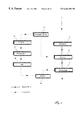
- FIG. 2 shows a signal flow diagram of an embodiment of the method according to the invention for controlling thermoacoustic vibrations
- FIG. 3 shows a fluid flow diagram of an embodiment of the method according to the invention for controlling thermoacoustic vibrations
- FIG. 4 shows a fluid flow diagram of a further embodiment of the method according to the invention for controlling thermoacoustic vibrations
- FIG. 5 shows, for an exemplary embodiment, a plot of the pressure fluctuations relative to the pressure fluctuations without control (100%) as a function of the relative phase between the measured measuring signal (sensor signal) and the instantaneous acoustic excitation;
- FIG. 6 shows an annular combustor carried out according to the invention
- FIG. 7 shows a further annular combustor carried out according to the invention.
- FIG. 8 shows a further annular combustor carried out according to the invention.
- FIG. 9 shows a silo combustor carried out according to the invention.
- FIG. 10 shows a combustor of a heating boiler carried out according to the invention.
- FIG. 2 a signal flow diagram
- the acoustic driver 10 To activate the acoustic driver 10 , a closed control loop is used. For noise suppression, the pressure or luminescence signal measured in the combustion chamber 16 is filtered (reference numeral 20 ), phase-shifted (reference numeral 22 ) and amplified (reference numeral 24 ). In the signal flow diagram of FIG. 2, the acoustic driver 10 introduces the acoustic energy into the air feed 12 , that is, into the flow upstream of the burner.
- the chamber 16 which in this case comprises the combustion chamber, is arranged adjacent to the burner 14 .
- the measurement of the above mentioned pressure or luminescence signal takes place in one of the chambers of the combustion system (either in the plenum upstream of the combustor which serves for reduction of turbulence or in the combustion chamber itself).
- the control loop is closed.
- FIG. 3 and FIG. 4 show two possible arrangements of the controlling devices and the related signal path relative to the flow path of the working gas through the combustor.
- the flow path is indicated by a continuous line while the signal path is drawn in in dotted lines.
- the arrangement shown in FIG. 3 corresponds to the embodiment of FIG. 2 .
- a sensor 18 is arranged in or adjacent to the combustion chamber 16 whereby the signal of this sensor is being measured and transferred to signal conditioning device(s).
- signal conditioning device(s) it might be also appropriate—and in some cases it might be advantageous—to measure the control loop input signal within the burner 14 or even within the air feed 12 with lower temperatures of the working gas.
- the signal e.g.
- a pressure signal which corresponds to the pressure fluctuations of the working gas in the combustion chamber 16 (a fluctuation value (RMS) would be sufficient for the purposes of the discussed instability control loop)—is then filtered (reference numeral 20 ), phase shifted (reference numeral 22 ) with an optimal phase shift adapted to the actual working condition (the relationship between working condition and optimal phase shift may be experimentally determined), amplified (reference numeral 24 ) by an appropriate amplification factor and finally fed into the acoustic driver device 10 .
- the acoustic driver 10 e.g.
- one loudspeaker or a plurality of loudspeakers or one or more vibrating walls limiting the fluid flow path or even combinations thereof acts on the fluid flow thereby inducing acoustic excitations of the shear layers.
- acoustic excitations i.e. pressure fluctuations particularly within the shear layer
- an appropriate phase shift as well as an appropriate amplifying factor is chosen, the development of coherent structures in the combustion chamber is prevented or at least diminshed by this superposition. This results in a more homogeneous temporal and spatial velocity and pressure profile of the fluid flow in the combustor and, thus, to a more homogeneous combustion process with reduced emission and increased efficiency.
- the embodiment shown in FIG. 4 differs from the embodiment of FIG. 3 in that the acoustic driver 10 acts on the burner directly. This is effected by positioning the acoustic driver 10 , e.g. a loudspeaker, in the burner 14 or immediately adjacent to the burner 14 .
- the embodiment of the invention according to FIG. 3 is advantageous in that generated acoustic vibrations directly impact the flow in the burner 14 . No damping of the induced acoustic excitations occurs due to the crossover between the air feed 12 and the burner 14 /the combustion chamber 16 . However, a shear layer, which exists in the air feed 12 , or the respective flow with this respective flow later forming into a shear layer, is still underdeveloped in an earlier stage of evolution or formation.
- any actuator positioned in the burner or immediately adjacent to the burner has to withstand very high temperatures.
- the actuators In both cases the actuators have to be positioned so as to directly act on the evolving or existing shear layers of the fluid flow, thus, introducing—at least to a great extent—the acoustic excitations into these shear layers. Therefore, the optimal position for an actuator has to be determined for every combustor configuration separately, either experimentally or by flow calculations. For this it is advantageous to determine the position of the shear layers first.
- FIG. 5 the results of an experimental analysis of the pressure fluctuations in an exemplary embodiment of the invention, in which the combustion system was susceptible to axially symmetrical, thermoacoustic fluctuations at a frequency of 104 Hz, are depicted.
- the pressure fluctuations under control of a pressure signal (open squares) and of an OH luminescence signal (solid circles) relative to the pressure fluctuations without control (100%) are shown in FIG. 5 .
- the acoustic excitation is effected by loudspeakers arranged inside the combustion system. Initial tests showed that an acoustic excitation upstream of the burner was more effective than an excitation downstream of the burner, so that the further experiments were carried out with acoustic excitation upstream of the burner.
- a B&K water-cooled microphone recorded the acoustic resonances of the chamber.
- the signals were pre-amplified, bandpass-filtered and phase-shifted.
- the phase shift was varied systematically between 0° and 360°.
- the resulting signal formed the trigger for a signal generator, which activated the loudspeaker via an audio amplifier.
- FIG. 5 shows that the pressure amplitudes are reduced by about 70% if a suitable relative phase is selected (open squares).
- an OH chemiluminescence signal was recorded by two optical fiber probes as a measure of the heat-release rate.
- a reduction in the pressure amplitudes by about 60% was thus achieved (solid circles).
- the different phase angles at which the maximum suppressions were obtained for the microphone based system compared to the OH based controller are due to the different locations of the sensors (microphone or fiber probe) and the difference in the type of signals measured. So in this case, the phase of the pressure signal changed in axial direction because the end conditions were not fully reflecting. Therefore, the difference in the sensors' locations had an effect on the phase difference between the signals.
- a phase difference was introduced by the phase characteristics of the sensors themselves.
- FIG. 6 shows an annular combustor being carried out according to the invention.
- the working gas usually air
- the working gas flows from the compressor 30 which is arranged upstream of the combustor to a splitter device 32 which divides the flow into two parts.
- the first part 34 i.e. the fluid which flows closer to the center line 36 of the turbomachine, is guided along a flow path to an axial position which is close to the exit plane of the combustor. Most of this first part fluid flow 34 is then reversed and guided along a small annular channel 37 back into the plenum 12 which is arranged ahead of the combustion chamber 16 . Following this small channel 37 the fluid flow also serves as a coolant for cooling the combustor chamber walls.
- a small part of the first part fluid flow flows directly through a slit 39 into the outlet flow of the combustion chamber 16 thereby cooling the hub wall of the turbine inlet 40 .
- the second part 35 of the fluid flow which is guided in a radial direction out of the center of the turbomachine flows in a first step along the inward outer side of the combustion chamber 16 and the plenum 12 .
- the flow is then guided along the head of the plenum 12 and finally turns its flow direction again, thus, flowing along the outward outer side of the plenum 12 and the combustion chamber 16 .
- the second part fluid flow 35 enters a second small annular channel 38 arranged on the outer side of the combustion chamber 16 and is guided into the plenum 12 .
- the flow through this channel also serves as a coolant, thereby cooling the outer wall of the combustion chamber 16 .
- the plenum 12 of the combustor is separated from the combustion chamber 16 by the outlet of a burner 14 .
- the burner 14 is only shown schematically and, thus, not in detail.
- a typical burner which e.g. would be suitable for use in this embodiment, is presented in the publications of Sattelmayer T. et.al. “Second-generation low-emission combustors for ABB gas turbines: burner development and test at atmospheric pressure”, Journal of Engineering for Gas Turbines and Power, 114, 1992, which is incorporated with reference herewith.
- At least part of the working gas of the plenum is guided from the plenum 12 into the burner 14 thereby advantageously inducing swirl within the flow.
- fuel is injected into the flow by means of a suitable injection device and mixed with the working gas.
- the thus premixed flow finally enters the combustion chamber 16 wherein the combustion takes place.
- Additional working gas may enter the combustion chamber 16 through slits 41 arranged next to the orifice 40 of the burner.
- FIG. 6 shows the velocity profile 50 of the flow in the combustion chamber 16 in the direction of the combustion chamber axis.
- This velocity profile 50 shows two peaks of high velocity. Areas of slow velocity are present adjacent the walls of the combustion chamber 16 and in the center of the chamber. The latter area of slow velocity results from the recirculating flow within the combustion chamber 16 which is required for flame stabilizing purposes. Shear layers exist in regions of changing flow velocities of one fluid flow or of several fluid flows abutting each other.
- the most relevant shear layers 51 of the flow in the combustion chamber 16 in view of the invention are indicated in FIG. 6 .
- Acoustic excitations for damping and controlling thermoacoustic vibrations of the flow should become effective in one or more of these layers 51 , thereby, gaining profit from the natural amplification within these shear layers when going through the combustion chamber.
- At least one acoustic driver 10 is installed in the combustor as shown in FIG. 6 .
- several acoustic drivers are—preferably equidistant—distributed around the circumference of the combustor.
- the acoustic driver/these acoustic drivers 10 in this case loudspeakers, is/are positioned so as to directly communicate with the flow in the combustion chamber 16 .
- any acoustic vibrations generated by the acoustic drivers 10 are directly introduced into at least one of the depicted shear layers 51 .
- the acoustic drivers have to be installed not too far downstream of the flow in the combustion chamber.
- the acoustic drivers are installed within the first third of the axial length of the combustion chamber, most preferably within the first quarter.
- a position too close to the orifice of the premixing device could also be disadvantageous as the introduced acoustic vibrations could be extinguished at least to some extent by antagonistic flow phenomena, in particular the separated corner flow.
- the acoustic driver is preferably installed downstream around 10% of the axial length of the combustion chamber.
- the working principle of the acoustic driver 10 of FIG. 6 is the same as of a normal loudspeaker.
- the acoustic driver is driven by an electric signal which according to the invention is generated from a sensor that records either pressure fluctuations or heat-release fluctuations in the combustion chamber.
- a pressure sensor 18 is arranged upstream of the acoustic driver 10 with the pressure sensor 18 measuring the wall pressure. The pressure signal is converted into an electrical signal and transmitted to a signal conditioning device.
- This signal conditioning device includes a mechanism for filtering the signal (reference numeral 20 ), preferably bandpass-filtering, a mechanism for phase-shifting the signal (reference numeral 22 ) and, moreover, a mechanism for amplifying the filtered and phase-shifted signal (reference numeral 24 ).
- this signal conditioning device comprises analogous components (filter-bank, etc.) or a micropocessor which is able to run the desired conditioning steps in real-time. For signal generation it is possible either to install only one sensor around the circumference of the combustor or to use a plurality of sensors distributed around the circumference of the combustor with each sensor being assigned to one acoustic driver.
- every acoustic device in case there is more than one acoustic driver arranged is supplied with the same driving signal.
- This driving signal can be phase-adapted according to the respective circumferential position of the acoustic driver for example in case of assuming a travelling sine-wave around the circumference. But with only one sensor it is not possible to take real two-dimensional effects into account. In the later case (when a plurality of sensors are arranged around the circumference) it is also possible to take two-dimensional effects into account.
- each acoustic driver can be driven in dependence on the local flow.
- any pressure oscillations due to eigenmodes of the combustor system or due to external or internal excitation shall be damped.
- By means of the effect of natural amplification of pressure fluctuations which are introduced into the shear layers of the combustor flow it is possible to damp pressure oscillations of the combustor flow by the input of acoustic vibrations with only a small energy content. This finally results in a more homogeneous combustor flow and, therefore, in a more homogeneous combustion with a reduced pollutant emission.
- FIG. 7 another, alternative embodiment of the invention is shown.
- the flow path of the annular combustor depicted in this figure as well as the premixing device (burner) correspond to the respective ones shown in FIG. 6 .
- the acoustic driver 10 in this case a loudspeaker; it might also be a movable side wall of the plenum
- the pressure sensor 18 is positioned to measure pressure fluctuations within the plenum 12 .
- the signal transfer and conditioning is the same as presented and discussed in FIG. 6 .
- For signal generation it is possible either to install only one sensor around the circumference of the combustor or to use a plurality of sensors distributed around the circumference of the combustor with each sensor being assigned to one acoustic driver.
- This embodiment is advantageous in that the temperature of the fluid in the plenum 12 is much lower than of the fluid in the combustion chamber 16 . Accordingly, the sensor 18 positioned adjacent the plenum 12 does not suffer the same high temperatures as when positioned adjacent the combustion chamber. Thus, this sensor will have a longer lifetime or can be cheaper in its design.
- the acoustic excitations of the acoustic driver 10 are fed into the plenum 12 and are transmitted to the shear layers which form either in the plenum or in the combustion chamber 16 .
- positioning of the acoustic driver and the sensor either communicating with the plenum or with the combustion chamber is more effective in terms of energy required to damp fluid oscillations. Accordingly, this positioning is dependent on the individual design of the respective combustor.
- FIG. 8 it is also possible to combine both arrangements of the acoustic drivers and sensors presented in the FIGS. 6 and 7 in one embodiment.
- One acoustic driver 10 b is arranged communicating with the plenum 12 .
- One further acoustic driver 10 a is arranged communicating with the combustion chamber 16 .
- each acoustic driver is individually driven by a signal which is generated by a separated sensor ( 18 a, 18 b ). Therefore, a very effective and locally adapted damping of flow oscillations can be achieved.
- FIG. 9 a silo combustor is shown which is carried out according to the invention.
- the fluid flow to the combustor (usually air flow) is indicated by arrows.
- the fluid enters the combustion chamber either through the premixing devices 14 arranged on top of the combustion chamber 16 or through slits 41 next to the orifices 40 of the premixing devices 14 .
- the premixing devices 14 which are only schematically shown in FIG. 9 are well known in the state of the art.
- acoustic drivers 10 a, 10 b, 10 c, 10 d are arranged whereby two are in communication with the plenum 12 and two directly communicate with the combustion chamber 16 .
- a plurality of acoustic drivers is preferably arranged on the circumference of the silo combustor.
- signal generating devices one or more sensors and signal conditioning devices for generating the driving signal for driving the acoustic drivers.
- the working principle of the acoustic drivers as well as the advantages is in parallel to the above discussed items.
- FIG. 8 a further preferred embodiment of the invention is shown in FIG. 8 .
- a combustor of a heating boiler which comprises an indraught 42 , a small plenum 12 , a fuel conduit 43 , a premixing device 14 , a combustion chamber 16 and heating pipes 44 .
- the fuel is injected and mixed with air in the premixing device.
- the combustion takes place in the combustion chamber as indicated in FIG. 10 .
- the combustor shown in FIG. 10 furthermore comprises two acoustic drivers 10 a, 10 b.
- One acoustic driver 10 b is positioned next to the plenum 12 being in communication with the fluid in this plenum 12 .
- acoustic excitations are introduced into the gas flow in the plenum. These acoustic vibrations are transferred through the premixing device 14 into the combustion chamber 16 . Accordingly, any shear layers evolving in the combustion chamber 16 are already superposed by these acoustic vibrations. In this combustion chamber shear layers evolve in particular as a consequence of the jet-type outflow of the fluid flow out of the premixing device 14 and as a consequence of the turning of the flow in the combustion chamber 16 .
- FIG. 10 can either be arranged in combination with each other or in an arrangement of only one acoustic driver. Not shown in FIG. 10 are the signal generating devices (signal sensor and signal conditioning device) which are carried out in parallel to the embodiments shown in FIGS. 6 to 8 .
Abstract
Description
Claims (13)
Priority Applications (1)
| Application Number | Priority Date | Filing Date | Title |
|---|---|---|---|
| US09/404,820 US6464489B1 (en) | 1997-11-24 | 1999-09-24 | Method and apparatus for controlling thermoacoustic vibrations in a combustion system |
Applications Claiming Priority (4)
| Application Number | Priority Date | Filing Date | Title |
|---|---|---|---|
| EP97810902 | 1997-11-24 | ||
| EP97810902A EP0918152A1 (en) | 1997-11-24 | 1997-11-24 | Method and apparatus for controlling thermo-acoustic vibratins in combustion chambers |
| US19617098A | 1998-11-20 | 1998-11-20 | |
| US09/404,820 US6464489B1 (en) | 1997-11-24 | 1999-09-24 | Method and apparatus for controlling thermoacoustic vibrations in a combustion system |
Related Parent Applications (1)
| Application Number | Title | Priority Date | Filing Date |
|---|---|---|---|
| US19617098A Continuation-In-Part | 1997-11-24 | 1998-11-20 |
Publications (1)
| Publication Number | Publication Date |
|---|---|
| US6464489B1 true US6464489B1 (en) | 2002-10-15 |
Family
ID=26148097
Family Applications (1)
| Application Number | Title | Priority Date | Filing Date |
|---|---|---|---|
| US09/404,820 Expired - Lifetime US6464489B1 (en) | 1997-11-24 | 1999-09-24 | Method and apparatus for controlling thermoacoustic vibrations in a combustion system |
Country Status (1)
| Country | Link |
|---|---|
| US (1) | US6464489B1 (en) |
Cited By (46)
| Publication number | Priority date | Publication date | Assignee | Title |
|---|---|---|---|---|
| US6546729B2 (en) * | 2000-11-25 | 2003-04-15 | Alstom (Switzerland) Ltd | Damper arrangement for reducing combustion-chamber pulsations |
| US20050016181A1 (en) * | 2002-12-07 | 2005-01-27 | Ephraim Gutmark | Method and device for affecting thermoacoustic oscillations in combustion systems |
| US20050016180A1 (en) * | 2002-12-07 | 2005-01-27 | Ephraim Gutmark | Method and device for affecting thermoacoustic oscillations in combustion systems |
| US20050076644A1 (en) * | 2003-10-08 | 2005-04-14 | Hardwicke Canan Uslu | Quiet combustor for a gas turbine engine |
| WO2005093326A2 (en) * | 2004-03-29 | 2005-10-06 | Alstom Technology Ltd | Gas turbine combustion chamber and corresponding operating method |
| US20060123793A1 (en) * | 2003-10-14 | 2006-06-15 | Pratt & Whitney Canada Corp. | Aerodynamic trip for a combustion system |
| DE102005001807A1 (en) * | 2005-01-13 | 2006-07-20 | Air Liquide Deutschland Gmbh | Process for heating an industrial furnace and apparatus therefor |
| US20060213200A1 (en) * | 2005-03-25 | 2006-09-28 | Honeywell International, Inc. | System and method for turbine engine adaptive control for mitigation of instabilities |
| US20060228658A1 (en) * | 2003-10-14 | 2006-10-12 | Paschereit Christian O | Apparatus and method for testing combustion |
| EP1724527A1 (en) * | 2005-05-13 | 2006-11-22 | Siemens Aktiengesellschaft | Combustion chamber and method of suppressing combustion vibrations |
| US20070224559A1 (en) * | 2005-03-30 | 2007-09-27 | Alexander Ni | Combustion Chamber |
| US20080087019A1 (en) * | 2006-06-01 | 2008-04-17 | Macquisten Michael A | Combustion chamber for a gas turbine engine |
| EP1962018A1 (en) * | 2002-12-23 | 2008-08-27 | Rolls-Royce plc | Combustion chamber for gas turbine engine |
| US20080216481A1 (en) * | 2003-12-16 | 2008-09-11 | Ansaldo Energia S.P.A. | System for Damping Thermo-Acoustic Instability in a Combustor Device for a Gas Turbine |
| EP1990579A1 (en) * | 2007-05-10 | 2008-11-12 | Siemens Aktiengesellschaft | Device and method for measuring acoustic oscillations in the fluid flow and gas turbine facility with such a device |
| US20090178414A1 (en) * | 2008-01-14 | 2009-07-16 | United Technologies Corporation | Flame holder for minimizing combustor screech |
| US20100101208A1 (en) * | 2008-10-29 | 2010-04-29 | United Technologies Corp. | Systems and Methods Involving Reduced Thermo-Acoustic Coupling of Gas Turbine Engine Augmentors |
| EP2206954A2 (en) * | 2009-01-08 | 2010-07-14 | General Electric Company | Systems and Methods for Detecting a Flame in a Fuel Nozzle of a Gas Turbine |
| US20110048021A1 (en) * | 2009-08-31 | 2011-03-03 | General Electric Company | Acoustically stiffened gas turbine combustor supply |
| US8028512B2 (en) | 2007-11-28 | 2011-10-04 | Solar Turbines Inc. | Active combustion control for a turbine engine |
| US20110311924A1 (en) * | 2010-06-22 | 2011-12-22 | Carrier Corporation | Low Pressure Drop, Low NOx, Induced Draft Gas Heaters |
| WO2012041842A1 (en) | 2010-09-27 | 2012-04-05 | Glaxosmithkline Biologicals S.A. | Vaccine |
| US20120111019A1 (en) * | 2010-11-09 | 2012-05-10 | General Electric Company Global Research | System and method for combustion dynamics control by acoustic control/cancellation of fuel flow fluctuation at fuel injection location |
| US20120260657A1 (en) * | 2009-09-21 | 2012-10-18 | Alstom Technology Ltd | Combustor of a gas turbine |
| US20120279229A1 (en) * | 2011-05-05 | 2012-11-08 | Hanspeter Zinn | Method for protecting a gas turbine engine against high dynamical process values and gas turbine engine for conducting the method |
| EP2559945A1 (en) * | 2011-08-17 | 2013-02-20 | Siemens Aktiengesellschaft | Combustion arrangement and turbine comprising a damping facility |
| US8437941B2 (en) | 2009-05-08 | 2013-05-07 | Gas Turbine Efficiency Sweden Ab | Automated tuning of gas turbine combustion systems |
| US20130133331A1 (en) * | 2009-02-02 | 2013-05-30 | General Electric Company | System and method for reducing combustion dynamics in a turbomachine |
| JP2013167396A (en) * | 2012-02-15 | 2013-08-29 | Mitsubishi Heavy Ind Ltd | Acoustic damper, combustor and gas turbine |
| US20130283799A1 (en) * | 2012-04-25 | 2013-10-31 | Solar Turbines Inc. | Resonance damper for damping acoustic oscillations from combustor |
| US8973365B2 (en) | 2010-10-29 | 2015-03-10 | Solar Turbines Incorporated | Gas turbine combustor with mounting for Helmholtz resonators |
| US20150101332A1 (en) * | 2013-10-11 | 2015-04-16 | Alstom Technology Ltd | Combustion chamber of a gas turbine with improved acoustic damping |
| US20150219016A1 (en) * | 2014-02-03 | 2015-08-06 | General Electric Company | System and method for operating a gas turbine |
| US9267443B2 (en) | 2009-05-08 | 2016-02-23 | Gas Turbine Efficiency Sweden Ab | Automated tuning of gas turbine combustion systems |
| US9354618B2 (en) | 2009-05-08 | 2016-05-31 | Gas Turbine Efficiency Sweden Ab | Automated tuning of multiple fuel gas turbine combustion systems |
| US20160298847A1 (en) * | 2015-04-07 | 2016-10-13 | General Electric Company | System and method for tuning resonators |
| US9671797B2 (en) | 2009-05-08 | 2017-06-06 | Gas Turbine Efficiency Sweden Ab | Optimization of gas turbine combustion systems low load performance on simple cycle and heat recovery steam generator applications |
| US20170321895A1 (en) * | 2016-05-03 | 2017-11-09 | General Electric Company | High frequency acoustic damper for combustor liners |
| US20180142891A1 (en) * | 2015-06-12 | 2018-05-24 | Ifta Ingenieurburo Fur Thermoakustic Gmbh | Thermoacoustic precursor method and apparatus |
| US10036266B2 (en) | 2012-01-17 | 2018-07-31 | United Technologies Corporation | Method and apparatus for turbo-machine noise suppression |
| US11092083B2 (en) | 2017-02-10 | 2021-08-17 | General Electric Company | Pressure sensor assembly for a turbine engine |
| US11326780B2 (en) * | 2017-03-24 | 2022-05-10 | Mitsubishi Power, Ltd. | Resonant sound absorbing device of gas turbine combustor, gas turbine combustor including the same, and gas turbine |
| US11421877B2 (en) | 2017-08-29 | 2022-08-23 | General Electric Company | Vibration control for a gas turbine engine |
| CN115143488A (en) * | 2022-07-01 | 2022-10-04 | 中国人民解放军国防科技大学 | Air heater combustion instability control method and system |
| US20230003383A1 (en) * | 2020-03-23 | 2023-01-05 | Mitsubishi Heavy Industries, Ltd. | Combustor and gas turbine provided with same |
| US20230033194A1 (en) * | 2020-01-20 | 2023-02-02 | Siemens Energy Global GmbH & Co. KG | Resonator ring for combustion chamber systems |
Citations (19)
| Publication number | Priority date | Publication date | Assignee | Title |
|---|---|---|---|---|
| US2807931A (en) * | 1951-06-16 | 1957-10-01 | Jr Albert G Bodine | Control of combustion instability in jet engines |
| US4044203A (en) * | 1972-11-24 | 1977-08-23 | National Research Development Corporation | Active control of sound waves |
| US4490841A (en) * | 1981-10-21 | 1984-12-25 | Sound Attenuators Limited | Method and apparatus for cancelling vibrations |
| US4784600A (en) * | 1986-10-08 | 1988-11-15 | Prutech Ii | Low NOx staged combustor with swirl suppression |
| US4801261A (en) * | 1987-03-19 | 1989-01-31 | Eagleair, Inc. | Apparatus and method for delivery of combustion air in multiple zones |
| US4909731A (en) * | 1986-03-06 | 1990-03-20 | Sonotech, Inc. | Method and apparatus for conducting a process in a pulsating environment |
| US4934926A (en) * | 1988-03-25 | 1990-06-19 | Agency Of Industrial Science & Technology, Ministry Of International Trade & Industry | Method and apparatus for monitoring and controlling burner operating air equivalence ratio |
| US5169302A (en) * | 1989-12-22 | 1992-12-08 | Asea Brown Boveri Ltd. | Burner |
| US5211705A (en) * | 1987-03-19 | 1993-05-18 | Damper Design, Inc. | Apparatus and method for delivery of combustion air in multiple zones |
| US5233540A (en) * | 1990-08-30 | 1993-08-03 | The Boeing Company | Method and apparatus for actively reducing repetitive vibrations |
| US5249954A (en) * | 1992-07-07 | 1993-10-05 | Electric Power Research Institute, Inc. | Integrated imaging sensor/neural network controller for combustion systems |
| US5299930A (en) * | 1992-11-09 | 1994-04-05 | Forney International, Inc. | Low nox burner |
| US5373695A (en) * | 1992-11-09 | 1994-12-20 | Asea Brown Boveri Ltd. | Gas turbine combustion chamber with scavenged Helmholtz resonators |
| US5428951A (en) * | 1993-08-16 | 1995-07-04 | Wilson; Kenneth | Method and apparatus for active control of combustion devices |
| US5431008A (en) * | 1990-02-21 | 1995-07-11 | Noise Cancellation Technologies, Inc. | Active control of machine performance |
| US5575144A (en) * | 1994-11-28 | 1996-11-19 | General Electric Company | System and method for actively controlling pressure pulses in a gas turbine engine combustor |
| US5676538A (en) * | 1993-06-28 | 1997-10-14 | General Electric Company | Fuel nozzle for low-NOx combustor burners |
| US5719791A (en) * | 1995-03-17 | 1998-02-17 | Georgia Tech Research Corporation | Methods, apparatus and systems for real time identification and control of modes of oscillation |
| US5784889A (en) * | 1995-11-17 | 1998-07-28 | Asea Brown Boveri Ag | Device for damping thermoacoustic pressure vibrations |
-
1999
- 1999-09-24 US US09/404,820 patent/US6464489B1/en not_active Expired - Lifetime
Patent Citations (20)
| Publication number | Priority date | Publication date | Assignee | Title |
|---|---|---|---|---|
| US2807931A (en) * | 1951-06-16 | 1957-10-01 | Jr Albert G Bodine | Control of combustion instability in jet engines |
| US4044203A (en) * | 1972-11-24 | 1977-08-23 | National Research Development Corporation | Active control of sound waves |
| US4490841A (en) * | 1981-10-21 | 1984-12-25 | Sound Attenuators Limited | Method and apparatus for cancelling vibrations |
| US4909731A (en) * | 1986-03-06 | 1990-03-20 | Sonotech, Inc. | Method and apparatus for conducting a process in a pulsating environment |
| US4784600A (en) * | 1986-10-08 | 1988-11-15 | Prutech Ii | Low NOx staged combustor with swirl suppression |
| US4801261A (en) * | 1987-03-19 | 1989-01-31 | Eagleair, Inc. | Apparatus and method for delivery of combustion air in multiple zones |
| US5211705A (en) * | 1987-03-19 | 1993-05-18 | Damper Design, Inc. | Apparatus and method for delivery of combustion air in multiple zones |
| US4934926A (en) * | 1988-03-25 | 1990-06-19 | Agency Of Industrial Science & Technology, Ministry Of International Trade & Industry | Method and apparatus for monitoring and controlling burner operating air equivalence ratio |
| US5169302A (en) * | 1989-12-22 | 1992-12-08 | Asea Brown Boveri Ltd. | Burner |
| US5431008A (en) * | 1990-02-21 | 1995-07-11 | Noise Cancellation Technologies, Inc. | Active control of machine performance |
| US5233540A (en) * | 1990-08-30 | 1993-08-03 | The Boeing Company | Method and apparatus for actively reducing repetitive vibrations |
| US5249954A (en) * | 1992-07-07 | 1993-10-05 | Electric Power Research Institute, Inc. | Integrated imaging sensor/neural network controller for combustion systems |
| US5373695A (en) * | 1992-11-09 | 1994-12-20 | Asea Brown Boveri Ltd. | Gas turbine combustion chamber with scavenged Helmholtz resonators |
| US5299930A (en) * | 1992-11-09 | 1994-04-05 | Forney International, Inc. | Low nox burner |
| US5676538A (en) * | 1993-06-28 | 1997-10-14 | General Electric Company | Fuel nozzle for low-NOx combustor burners |
| US5428951A (en) * | 1993-08-16 | 1995-07-04 | Wilson; Kenneth | Method and apparatus for active control of combustion devices |
| US5575144A (en) * | 1994-11-28 | 1996-11-19 | General Electric Company | System and method for actively controlling pressure pulses in a gas turbine engine combustor |
| US5719791A (en) * | 1995-03-17 | 1998-02-17 | Georgia Tech Research Corporation | Methods, apparatus and systems for real time identification and control of modes of oscillation |
| US5784300A (en) * | 1995-03-17 | 1998-07-21 | Georgia Tech Research Corporation | Methods, apparatus and systems for real time identification and control modes of oscillation |
| US5784889A (en) * | 1995-11-17 | 1998-07-28 | Asea Brown Boveri Ag | Device for damping thermoacoustic pressure vibrations |
Non-Patent Citations (13)
| Title |
|---|
| C.O. Paschereit, E. Gutmark, and W. Weisenstein, "Acoustic and Fuel Modulation Control For Reduction of Thermoacoustic Instabilities", In Fourteenth International Symposium on Airbreathing Engines, Florence, Italy, Sep. 5-10, 1999, pp. 1-8. |
| C.O. Paschereit, E. Gutmark, and W. Weisenstein, "Acoustic Control of Combustion Instabilities and Emissions in a Gas-Turbine Combustor", In Proceedings of the 1998 IEEE International Conference on Control Applications, Sep. 1-4, 1998, pp. 1-5. |
| C.O. Paschereit, E. Gutmark, and W. Weisenstein, "Coherent Structures in Swirling Flows and Their Role in Acoustic Combustion Control", Accepted for publication in Physics of Fluids, 1999, pp. 1-42. |
| C.O. Paschereit, E. Gutmark, and W. Weisenstein, "Control of Thermoacoustic Instabilities and Emissions in an Industrial Type Gas-Turbine Combustor", In 27th International Symposium on Combustion, The Combustion Institute, Aug. 2-7, 1998, pp. 1-25. |
| C.O. Paschereit, E. Gutmark, and W. Weisenstein, "Excitation of Thermoacoustic Instabilities by the Interaction of Acoustics and Unstable Swirling Flow", Submitted to AIAA Journal, 1999, pp. 1-41. |
| C.O. Paschereit, E. Gutmark, and W. Weisenstein, "Flow-Acoustic Interactions as a Driving Mechanism for Thermoacoustic Instabilities", In 4th AIAA/CEAS Aeroacoustic Conference, number AIAA paper 98-2274, Toulouse, France, Jun. 2-4, 1998, pp. 1-13. |
| C.O. Paschereit, E. Gutmark, and W. Weisenstein, "Role of Coherent Structures in Acoustic Combustion Control", In 29th AIAA Fluid Dynamics Conference, number AIAA Paper 98-2433, Albuquerque, New Mexico, Jun. 15-18, 1998, pp. 1-13. |
| C.O. Paschereit, E. Gutmark, and W. Weisenstein, "Structure and Control of Thermoacoustic Instabilities in a Gas-Turbine Combustor", Combustion, Science and Technology, 138:213-232, 1998, pp. 1-30. |
| C.O. Paschereit, E. Gutmark, and W. Weisenstein, "Structure and Control of Thermoacoustic Instabilities in a Gas-Turbine Combustor", In 36th AIAA Aerospace Science Meeting and Exhibit, number AIAA paper 98-1067, Reno, Nevada, Jan. 12-15, 1998, pp. 1-9. |
| C.O. Paschereit, E. Gutmark, and W. Weisenstein, "Suppression of Combustion Instabilities by Acoustic Control of Shear Layer Properties", In U. Frisch, editor, Advances in Turbulence, pp. 293-296, Kluwer Academic Publishers, Dordrecht/Boston/London, 1998, pp. 1-4. |
| C.O. Paschereit, I. Wygnanski, and H.E. Fiedler, "Experimental Investigation of Subharmonic Resonance in an Axisymmetric Jet", J. Fluid Mech. (1995), vol. 283, pp. 365-407. |
| E. Gutmark, C.O. Paschereit, and W. Weisenstein, "Sources and Control of Thermoacoustic Instabilities in Gas-Turbines", In Sixth International Congress on Sound and Vibration, Lyngby, Denmark, Jul. 5-8, 1999, pp. 1-8. |
| E. Gutmark, C.O. Paschereit, W. Weisenstein, and B. Paikert, "Active Control of a Low Emission Swirl-Stabilised Combustor", In Bulletin of the American Physical Society / Division of Fluid Dynamics, Annual Meeting, San Francisco, California, USA, 1997, p. 1. |
Cited By (80)
| Publication number | Priority date | Publication date | Assignee | Title |
|---|---|---|---|---|
| US6546729B2 (en) * | 2000-11-25 | 2003-04-15 | Alstom (Switzerland) Ltd | Damper arrangement for reducing combustion-chamber pulsations |
| US20050016181A1 (en) * | 2002-12-07 | 2005-01-27 | Ephraim Gutmark | Method and device for affecting thermoacoustic oscillations in combustion systems |
| US20050016180A1 (en) * | 2002-12-07 | 2005-01-27 | Ephraim Gutmark | Method and device for affecting thermoacoustic oscillations in combustion systems |
| US7232308B2 (en) | 2002-12-07 | 2007-06-19 | Alstom Technology Ltd. | Method and device for affecting thermoacoustic oscillations in combustion systems |
| EP1962018A1 (en) * | 2002-12-23 | 2008-08-27 | Rolls-Royce plc | Combustion chamber for gas turbine engine |
| US20050076644A1 (en) * | 2003-10-08 | 2005-04-14 | Hardwicke Canan Uslu | Quiet combustor for a gas turbine engine |
| US20060123793A1 (en) * | 2003-10-14 | 2006-06-15 | Pratt & Whitney Canada Corp. | Aerodynamic trip for a combustion system |
| US20060228658A1 (en) * | 2003-10-14 | 2006-10-12 | Paschereit Christian O | Apparatus and method for testing combustion |
| US7457710B2 (en) * | 2003-10-14 | 2008-11-25 | Alstom Technology Ltd. | Apparatus and method for testing combustion |
| US7302802B2 (en) | 2003-10-14 | 2007-12-04 | Pratt & Whitney Canada Corp. | Aerodynamic trip for a combustion system |
| US7661267B2 (en) * | 2003-12-16 | 2010-02-16 | Ansaldo Energia S.P.A. | System for damping thermo-acoustic instability in a combustor device for a gas turbine |
| US20080216481A1 (en) * | 2003-12-16 | 2008-09-11 | Ansaldo Energia S.P.A. | System for Damping Thermo-Acoustic Instability in a Combustor Device for a Gas Turbine |
| WO2005093326A3 (en) * | 2004-03-29 | 2006-02-09 | Alstom Technology Ltd | Gas turbine combustion chamber and corresponding operating method |
| WO2005093326A2 (en) * | 2004-03-29 | 2005-10-06 | Alstom Technology Ltd | Gas turbine combustion chamber and corresponding operating method |
| DE102005001807A1 (en) * | 2005-01-13 | 2006-07-20 | Air Liquide Deutschland Gmbh | Process for heating an industrial furnace and apparatus therefor |
| US20060213200A1 (en) * | 2005-03-25 | 2006-09-28 | Honeywell International, Inc. | System and method for turbine engine adaptive control for mitigation of instabilities |
| US7406820B2 (en) | 2005-03-25 | 2008-08-05 | Honeywell International Inc. | System and method for turbine engine adaptive control for mitigation of instabilities |
| US20070224559A1 (en) * | 2005-03-30 | 2007-09-27 | Alexander Ni | Combustion Chamber |
| EP1724527A1 (en) * | 2005-05-13 | 2006-11-22 | Siemens Aktiengesellschaft | Combustion chamber and method of suppressing combustion vibrations |
| US7901203B2 (en) * | 2006-03-30 | 2011-03-08 | Alstom Technology Ltd. | Combustion chamber |
| US7857094B2 (en) * | 2006-06-01 | 2010-12-28 | Rolls-Royce Plc | Combustion chamber for a gas turbine engine |
| US20080087019A1 (en) * | 2006-06-01 | 2008-04-17 | Macquisten Michael A | Combustion chamber for a gas turbine engine |
| WO2008138828A1 (en) * | 2007-05-10 | 2008-11-20 | Siemens Aktiengesellschaft | Device and method for measuring acoustic vibrations in a fluid flow and a gas turbine installation with such a device |
| EP1990579A1 (en) * | 2007-05-10 | 2008-11-12 | Siemens Aktiengesellschaft | Device and method for measuring acoustic oscillations in the fluid flow and gas turbine facility with such a device |
| US8028512B2 (en) | 2007-11-28 | 2011-10-04 | Solar Turbines Inc. | Active combustion control for a turbine engine |
| US20090178414A1 (en) * | 2008-01-14 | 2009-07-16 | United Technologies Corporation | Flame holder for minimizing combustor screech |
| US7954328B2 (en) | 2008-01-14 | 2011-06-07 | United Technologies Corporation | Flame holder for minimizing combustor screech |
| US20100101208A1 (en) * | 2008-10-29 | 2010-04-29 | United Technologies Corp. | Systems and Methods Involving Reduced Thermo-Acoustic Coupling of Gas Turbine Engine Augmentors |
| US9759424B2 (en) | 2008-10-29 | 2017-09-12 | United Technologies Corporation | Systems and methods involving reduced thermo-acoustic coupling of gas turbine engine augmentors |
| EP2206954A2 (en) * | 2009-01-08 | 2010-07-14 | General Electric Company | Systems and Methods for Detecting a Flame in a Fuel Nozzle of a Gas Turbine |
| EP2206954A3 (en) * | 2009-01-08 | 2013-12-04 | General Electric Company | Systems and Methods for Detecting a Flame in a Fuel Nozzle of a Gas Turbine |
| US20130133331A1 (en) * | 2009-02-02 | 2013-05-30 | General Electric Company | System and method for reducing combustion dynamics in a turbomachine |
| US8437941B2 (en) | 2009-05-08 | 2013-05-07 | Gas Turbine Efficiency Sweden Ab | Automated tuning of gas turbine combustion systems |
| US11028783B2 (en) | 2009-05-08 | 2021-06-08 | Gas Turbine Efficiency Sweden Ab | Automated tuning of gas turbine combustion systems |
| US9267443B2 (en) | 2009-05-08 | 2016-02-23 | Gas Turbine Efficiency Sweden Ab | Automated tuning of gas turbine combustion systems |
| US9354618B2 (en) | 2009-05-08 | 2016-05-31 | Gas Turbine Efficiency Sweden Ab | Automated tuning of multiple fuel gas turbine combustion systems |
| US9671797B2 (en) | 2009-05-08 | 2017-06-06 | Gas Turbine Efficiency Sweden Ab | Optimization of gas turbine combustion systems low load performance on simple cycle and heat recovery steam generator applications |
| US9328670B2 (en) | 2009-05-08 | 2016-05-03 | Gas Turbine Efficiency Sweden Ab | Automated tuning of gas turbine combustion systems |
| US11199818B2 (en) | 2009-05-08 | 2021-12-14 | Gas Turbine Efficiency Sweden Ab | Automated tuning of multiple fuel gas turbine combustion systems |
| US10260428B2 (en) | 2009-05-08 | 2019-04-16 | Gas Turbine Efficiency Sweden Ab | Automated tuning of gas turbine combustion systems |
| US10509372B2 (en) | 2009-05-08 | 2019-12-17 | Gas Turbine Efficiency Sweden Ab | Automated tuning of multiple fuel gas turbine combustion systems |
| US20110048021A1 (en) * | 2009-08-31 | 2011-03-03 | General Electric Company | Acoustically stiffened gas turbine combustor supply |
| DE102010037078B4 (en) | 2009-09-01 | 2022-11-03 | General Electric Co. | Acoustically stiffened gas turbine combustor duct |
| US8661822B2 (en) * | 2009-09-01 | 2014-03-04 | General Electric Company | Acoustically stiffened gas turbine combustor supply |
| JP2011052954A (en) * | 2009-09-01 | 2011-03-17 | General Electric Co <Ge> | Acoustically stiffened gas turbine combustor supply |
| US8635874B2 (en) * | 2009-09-21 | 2014-01-28 | Alstom Technology Ltd | Gas turbine combustor including an acoustic damper device |
| US20120260657A1 (en) * | 2009-09-21 | 2012-10-18 | Alstom Technology Ltd | Combustor of a gas turbine |
| US20110311924A1 (en) * | 2010-06-22 | 2011-12-22 | Carrier Corporation | Low Pressure Drop, Low NOx, Induced Draft Gas Heaters |
| US9127837B2 (en) * | 2010-06-22 | 2015-09-08 | Carrier Corporation | Low pressure drop, low NOx, induced draft gas heaters |
| WO2012041842A1 (en) | 2010-09-27 | 2012-04-05 | Glaxosmithkline Biologicals S.A. | Vaccine |
| US8973365B2 (en) | 2010-10-29 | 2015-03-10 | Solar Turbines Incorporated | Gas turbine combustor with mounting for Helmholtz resonators |
| US8919131B2 (en) * | 2010-11-09 | 2014-12-30 | General Electric Company | System and method for combustion dynamics control by acoustic control/cancellation of fuel flow fluctuation at fuel injection location |
| CN102465764A (en) * | 2010-11-09 | 2012-05-23 | 通用电气公司 | System and method for combustion dynamics control |
| US20120111019A1 (en) * | 2010-11-09 | 2012-05-10 | General Electric Company Global Research | System and method for combustion dynamics control by acoustic control/cancellation of fuel flow fluctuation at fuel injection location |
| US9068512B2 (en) * | 2011-05-05 | 2015-06-30 | Alstom Technology Ltd. | Method for protecting a gas turbine engine against high dynamical process values and gas turbine engine for conducting the method |
| US20120279229A1 (en) * | 2011-05-05 | 2012-11-08 | Hanspeter Zinn | Method for protecting a gas turbine engine against high dynamical process values and gas turbine engine for conducting the method |
| CN103732992B (en) * | 2011-08-17 | 2016-03-09 | 西门子公司 | Burner, with damping device turbine and run the method for burner |
| WO2013023886A1 (en) * | 2011-08-17 | 2013-02-21 | Siemens Aktiengesellschaft | Combustion arrangement and turbine comprising a damping facility |
| US8955324B2 (en) | 2011-08-17 | 2015-02-17 | Siemens Aktiengesellschaft | Combustion arrangement and turbine comprising a damping facility |
| EP2559945A1 (en) * | 2011-08-17 | 2013-02-20 | Siemens Aktiengesellschaft | Combustion arrangement and turbine comprising a damping facility |
| CN103732992A (en) * | 2011-08-17 | 2014-04-16 | 西门子公司 | Combustion arrangement and turbine comprising a damping facility |
| US10036266B2 (en) | 2012-01-17 | 2018-07-31 | United Technologies Corporation | Method and apparatus for turbo-machine noise suppression |
| JP2013167396A (en) * | 2012-02-15 | 2013-08-29 | Mitsubishi Heavy Ind Ltd | Acoustic damper, combustor and gas turbine |
| US20130283799A1 (en) * | 2012-04-25 | 2013-10-31 | Solar Turbines Inc. | Resonance damper for damping acoustic oscillations from combustor |
| US20150101332A1 (en) * | 2013-10-11 | 2015-04-16 | Alstom Technology Ltd | Combustion chamber of a gas turbine with improved acoustic damping |
| US10180108B2 (en) | 2014-02-03 | 2019-01-15 | General Electric Company | System and method for operating a gas turbine |
| US20150219016A1 (en) * | 2014-02-03 | 2015-08-06 | General Electric Company | System and method for operating a gas turbine |
| US9556799B2 (en) * | 2014-02-03 | 2017-01-31 | General Electric Company | System and method for operating a gas turbine |
| US10088165B2 (en) * | 2015-04-07 | 2018-10-02 | General Electric Company | System and method for tuning resonators |
| US20160298847A1 (en) * | 2015-04-07 | 2016-10-13 | General Electric Company | System and method for tuning resonators |
| US20180142891A1 (en) * | 2015-06-12 | 2018-05-24 | Ifta Ingenieurburo Fur Thermoakustic Gmbh | Thermoacoustic precursor method and apparatus |
| US10948185B2 (en) * | 2015-06-12 | 2021-03-16 | Ifta Ingenieurburo Fur Thermoakustik Gmbh | Thermoacoustic precursor method and apparatus |
| US10197275B2 (en) * | 2016-05-03 | 2019-02-05 | General Electric Company | High frequency acoustic damper for combustor liners |
| US20170321895A1 (en) * | 2016-05-03 | 2017-11-09 | General Electric Company | High frequency acoustic damper for combustor liners |
| US11092083B2 (en) | 2017-02-10 | 2021-08-17 | General Electric Company | Pressure sensor assembly for a turbine engine |
| US11326780B2 (en) * | 2017-03-24 | 2022-05-10 | Mitsubishi Power, Ltd. | Resonant sound absorbing device of gas turbine combustor, gas turbine combustor including the same, and gas turbine |
| US11421877B2 (en) | 2017-08-29 | 2022-08-23 | General Electric Company | Vibration control for a gas turbine engine |
| US20230033194A1 (en) * | 2020-01-20 | 2023-02-02 | Siemens Energy Global GmbH & Co. KG | Resonator ring for combustion chamber systems |
| US20230003383A1 (en) * | 2020-03-23 | 2023-01-05 | Mitsubishi Heavy Industries, Ltd. | Combustor and gas turbine provided with same |
| CN115143488A (en) * | 2022-07-01 | 2022-10-04 | 中国人民解放军国防科技大学 | Air heater combustion instability control method and system |
Similar Documents
| Publication | Publication Date | Title |
|---|---|---|
| US6464489B1 (en) | Method and apparatus for controlling thermoacoustic vibrations in a combustion system | |
| US6461144B1 (en) | Method of controlling thermoacoustic vibrations in a combustion system, and combustion system | |
| US6840046B2 (en) | Method and apparatus for minimizing thermoacoustic vibrations in gas-turbine combustion chambers | |
| US4557106A (en) | Combustion system for a gas turbine engine | |
| US6205764B1 (en) | Method for the active damping of combustion oscillation and combustion apparatus | |
| US8485309B2 (en) | Apparatus and method for improving the damping of acoustic waves | |
| JP4059923B2 (en) | Method and apparatus for acoustic modulation of flame generated from a hybrid burner | |
| Poppe et al. | Control of NOx emissions in confined flames by oscillations | |
| Berenbrink et al. | Suppression of dynamic combustion instabilities by passive and active means | |
| JPH07190364A (en) | Method and equipment for damping thermal acoustic vibration | |
| US6196835B1 (en) | Burner | |
| US6490864B1 (en) | Burner with damper for attenuating thermo acoustic instabilities | |
| JP2012117807A (en) | Wide frequency response tunable resonator | |
| US6581385B2 (en) | Combustion device for generating hot gases | |
| Bhayaraju et al. | Effect of cooling liner on acoustic energy absorption and flame response | |
| Zähringer et al. | Helmholtz behavior and transfer function of an industrial fuel swirl burner used in heating systems | |
| US20020029573A1 (en) | Method for reducing thermoacoustic vibrations in turbo machines with a burner system | |
| GB2397643A (en) | A combustion chamber burner including a corrugated burner outlet | |
| US7232308B2 (en) | Method and device for affecting thermoacoustic oscillations in combustion systems | |
| Murugappan et al. | Characteristics and control of combustion instabilities in a swirl-stabilized spray combustor | |
| US7549857B2 (en) | Method and device for affecting thermoacoustic oscillations in combustion systems | |
| US6698209B1 (en) | Method of and appliance for suppressing flow eddies within a turbomachine | |
| Tran et al. | Passive control of the inlet acoustic boundary of a swirled turbulent burner | |
| O’Connor et al. | Mechanisms for flame response in a transversely forced flame | |
| US20050016181A1 (en) | Method and device for affecting thermoacoustic oscillations in combustion systems |
Legal Events
| Date | Code | Title | Description |
|---|---|---|---|
| AS | Assignment |
Owner name: ABB RESEARCH LTD., SWITZERLAND Free format text: ASSIGNMENT OF ASSIGNORS INTEREST;ASSIGNORS:GUTMARK, EPHRAIM;PASCHEREIT, CHRISTIAN OLIVIER;WEISENSTEIN, WOLFGANG;REEL/FRAME:010447/0760 Effective date: 19991130 |
|
| AS | Assignment |
Owner name: ALSTOM, FRANCE Free format text: ASSIGNMENT OF ASSIGNORS INTEREST;ASSIGNOR:ABB RESEARCH LTD.;REEL/FRAME:012232/0072 Effective date: 20001101 |
|
| AS | Assignment |
Owner name: ALSTOM, FRANCE Free format text: ASSIGNMENT OF ASSIGNORS INTEREST;ASSIGNOR:ABB RESEARCH LTD.;REEL/FRAME:013011/0578 Effective date: 20020523 |
|
| STCF | Information on status: patent grant |
Free format text: PATENTED CASE |
|
| FEPP | Fee payment procedure |
Free format text: PAYOR NUMBER ASSIGNED (ORIGINAL EVENT CODE: ASPN); ENTITY STATUS OF PATENT OWNER: LARGE ENTITY |
|
| FPAY | Fee payment |
Year of fee payment: 4 |
|
| FPAY | Fee payment |
Year of fee payment: 8 |
|
| AS | Assignment |
Owner name: ALSTOM TECHNOLOGY LTD, SWITZERLAND Free format text: ASSIGNMENT OF ASSIGNORS INTEREST;ASSIGNOR:ALSTOM;REEL/FRAME:028930/0507 Effective date: 20120523 |
|
| FPAY | Fee payment |
Year of fee payment: 12 |
|
| AS | Assignment |
Owner name: GENERAL ELECTRIC TECHNOLOGY GMBH, SWITZERLAND Free format text: CHANGE OF NAME;ASSIGNOR:ALSTOM TECHNOLOGY LTD;REEL/FRAME:038216/0193 Effective date: 20151102 |
|
| AS | Assignment |
Owner name: ANSALDO ENERGIA SWITZERLAND AG, SWITZERLAND Free format text: ASSIGNMENT OF ASSIGNORS INTEREST;ASSIGNOR:GENERAL ELECTRIC TECHNOLOGY GMBH;REEL/FRAME:041686/0884 Effective date: 20170109 |