EP1990579A1 - Device and method for measuring acoustic oscillations in the fluid flow and gas turbine facility with such a device - Google Patents
Device and method for measuring acoustic oscillations in the fluid flow and gas turbine facility with such a device Download PDFInfo
- Publication number
- EP1990579A1 EP1990579A1 EP07009448A EP07009448A EP1990579A1 EP 1990579 A1 EP1990579 A1 EP 1990579A1 EP 07009448 A EP07009448 A EP 07009448A EP 07009448 A EP07009448 A EP 07009448A EP 1990579 A1 EP1990579 A1 EP 1990579A1
- Authority
- EP
- European Patent Office
- Prior art keywords
- resonator
- gas turbine
- turbine plant
- vibrations
- incinerator
- Prior art date
- Legal status (The legal status is an assumption and is not a legal conclusion. Google has not performed a legal analysis and makes no representation as to the accuracy of the status listed.)
- Withdrawn
Links
Images

Classifications
-
- F—MECHANICAL ENGINEERING; LIGHTING; HEATING; WEAPONS; BLASTING
- F23—COMBUSTION APPARATUS; COMBUSTION PROCESSES
- F23R—GENERATING COMBUSTION PRODUCTS OF HIGH PRESSURE OR HIGH VELOCITY, e.g. GAS-TURBINE COMBUSTION CHAMBERS
- F23R3/00—Continuous combustion chambers using liquid or gaseous fuel
- F23R3/002—Wall structures
-
- F—MECHANICAL ENGINEERING; LIGHTING; HEATING; WEAPONS; BLASTING
- F23—COMBUSTION APPARATUS; COMBUSTION PROCESSES
- F23M—CASINGS, LININGS, WALLS OR DOORS SPECIALLY ADAPTED FOR COMBUSTION CHAMBERS, e.g. FIREBRIDGES; DEVICES FOR DEFLECTING AIR, FLAMES OR COMBUSTION PRODUCTS IN COMBUSTION CHAMBERS; SAFETY ARRANGEMENTS SPECIALLY ADAPTED FOR COMBUSTION APPARATUS; DETAILS OF COMBUSTION CHAMBERS, NOT OTHERWISE PROVIDED FOR
- F23M20/00—Details of combustion chambers, not otherwise provided for, e.g. means for storing heat from flames
- F23M20/005—Noise absorbing means
-
- F—MECHANICAL ENGINEERING; LIGHTING; HEATING; WEAPONS; BLASTING
- F23—COMBUSTION APPARATUS; COMBUSTION PROCESSES
- F23R—GENERATING COMBUSTION PRODUCTS OF HIGH PRESSURE OR HIGH VELOCITY, e.g. GAS-TURBINE COMBUSTION CHAMBERS
- F23R2900/00—Special features of, or arrangements for continuous combustion chambers; Combustion processes therefor
- F23R2900/00013—Reducing thermo-acoustic vibrations by active means
-
- F—MECHANICAL ENGINEERING; LIGHTING; HEATING; WEAPONS; BLASTING
- F23—COMBUSTION APPARATUS; COMBUSTION PROCESSES
- F23R—GENERATING COMBUSTION PRODUCTS OF HIGH PRESSURE OR HIGH VELOCITY, e.g. GAS-TURBINE COMBUSTION CHAMBERS
- F23R2900/00—Special features of, or arrangements for continuous combustion chambers; Combustion processes therefor
- F23R2900/00014—Reducing thermo-acoustic vibrations by passive means, e.g. by Helmholtz resonators
Definitions
- the present invention relates to an apparatus and a method for measuring sound vibrations in a fluid flow, in particular for measuring thermoacoustic sound vibrations in a combustion system of a gas turbine.
- the invention further relates to a gas turbine plant with such a device for measuring thermoacoustic oscillations.
- a gas turbine plant is a turbomachine, which usually comprises a compressor, an incinerator and a turbine.
- the compressor there is a compression of sucked air, which air is then admixed with a fuel.
- the incinerator comprises three parts: an air supply passage, the burners and the combustion chamber.
- the air supply passage is the space upstream of the burners in which the air compressed by the compressor flows before it reaches the burners.
- the fuel is injected through the burners.
- the burners open into the combustion chamber, in which the combustion of the mixture of compressed air and fuel takes place.
- the combustion exhaust gases are then fed to the gas turbine, in which the combustion exhaust gases are deprived of thermal energy and converted into mechanical work.
- the mechanical work is used on the one hand to drive the compressor and on the other hand to drive a consumer, for example a generator for generating electricity.
- thermoacoustic oscillations When burning in the combustion chamber, make sure that there is a stable flame. Instabilities of the flame in particular due to resonant combustion vibrations in the combustion exhaust gas and can lead to an increased pollutant emissions on the one hand and on the other hand Vibrations and vibrations of the combustion chamber cause, from a certain frequency - still called stability limit or hum limit - reduce the life of the combustion chamber and shorten the maintenance intervals. Such combustion oscillations in the combustion chamber, which occur due to thermal or acoustic disturbances, are further referred to as thermoacoustic oscillations.
- dampers are due to their predetermined volume in a position to effectively damp certain vibration frequencies in the combustion chamber.
- a damper assembly comprising a plurality of damping elements for the reduction of Brennschpulsationen, which damping elements are designed in the manner of Helmholtz resonators.
- a disadvantage of such damper arrangements is that they generally have a very large total volume, for example of about 40 liters.
- the present invention has for its object to enable early detection of disturbing sound vibrations in a fluid flow.
- the object is achieved by a device for measuring sound vibrations in a fluid flow, in particular for measuring thermoacoustic oscillations in a combustion system of a gas turbine plant, with an acoustic filter for amplifying or filtering of sound vibrations of a predetermined frequency bandwidth and the acoustic filter downstream pressure sensor for Capture and output the sound vibrations.
- the invention is based on the consideration that early detection of spurious vibrations is possible by monitoring the pressure fluctuations in the flow system by means of continuous pressure measurements or pressure measurements at predetermined time intervals.
- the acoustic filter is designed in the manner of an active filter to vibrations in one predetermined frequency bandwidth, in particular to increase vibrations in the range of a stability or humming of the system, so that by means of the pressure sensor, a particularly clear measurement signal is detected. In this case, frequencies of a greater bandwidth are measured than those for which the acoustic filter is calibrated.
- the acoustic filter is preferably designed such that it is permeable to a wider frequency range, but the vibrations in the predetermined frequency bandwidth are significantly enhanced.
- the acoustic filter is thus designed to filter out a smaller frequency bandwidth, which indicates the hum limit and thus is essential for the stability of the flow system. When approaching the hum limit, this results in a particularly clear measurement signal with a high signal-to-noise ratio.
- the device can be used after a corresponding calibration in different flow systems.
- the device is suitable for measuring thermoacoustic oscillations in an incinerator in a gas turbine. Thanks to the targeted filtering out of the sound vibrations with a frequency which indicates the hum limit, an early detection of flame instabilities takes place in the evaluation of the measurement signal, so that timely measures to stabilize the combustion process can be initiated and preferred.
- the acoustic filter is a resonator, in particular a Helmholz resonator.
- Resonators offer many design possibilities and play an important role in both acoustics and high-frequency technology, where they can be used as filters for very high frequencies.
- the resonator for amplifying different frequency bandwidths is adjustable.
- the frequency bandwidth that is amplified by the resonator in a simple manner to the thermoacoustic behavior adaptable to the flow system.
- no exchange of resonators is required here.
- At least a part of a wall of the resonator for adjusting a resonator volume is spatially variable. This results in a structurally particularly simple implementation of the adjustable resonator, by which the resonator volume and thus the resonator frequency can be influenced. In addition, a precise adjustment and in particular a continuous adjustment of the resonator volume to the operating requirements is possible.
- the movable part of the wall is designed as a piston.
- the piston can easily be displaced longitudinally to precisely adjust the volume of the resonator.
- the movable part of the wall is designed in the manner of a longitudinally displaceable neck of the resonator.
- the neck of the resonator can likewise be moved into or out of the resonator volume without great technical effort, as a result of which the resonator volume changes.
- At least one opening for supplying coolant into the resonator is provided on a wall of the resonator.
- the supply of coolant allows for permanent trouble-free operation of the resonator when used at very high temperatures, e.g. in the combustion chamber of a gas turbine plant.
- the resonator is exclusively for amplifying a predetermined, measured Frequency bandwidth provided and has a volume of less than 5 liters. Since the function of the resonator is limited only to its use as an acoustic filter, the resonator can be dimensioned significantly smaller than those known from the prior art resonators, which are used for damping the thermoacoustic oscillations. To filter out a given frequency bandwidth is usually sufficient, a single resonator whose volume does not exceed 5 liters. It is also possible to use several small resonators whose total volume is also in the order of 5 liters. Thus, a very space-saving and cost-effective implementation of the device would be given.
- the resonator can be used as a damper of the sound vibrations.
- the resonator is not only able to dampen the spurious, as previously known, but also to filter it out in the measurements by means of the pressure sensor.
- a plurality of acoustic filters are provided, which are set for amplifying sound vibrations of different frequency bandwidths.
- Particularly advantageous is the use of such a configuration in combination with acoustic filters whose volume is unchangeable, so that each filter is designed to filter only a predetermined frequency bandwidth.
- a particularly wide frequency range can be covered.
- a grouping of multiple acoustic filters in an array is also possible if the frequency bandwidths to be filtered out of some or all of the acoustic filters can be set.
- a control unit for evaluating the measurement signal of the pressure sensor and a control unit controlled by the control unit for influencing at least one flow parameter of the fluid flow, in particular an air and / or fuel supply are provided in response to the measurement signal.
- measurements of the pressure fluctuation in the flow system determine an approach to the hum limit.
- the adjusting device is controlled such that a change in the gas turbine power is effected. For example, an absolute value of the air supply and / or the fuel supply and / or the ratio of air supply to the fuel supply is set such that exceeding the hum limit is prevented.
- a gas turbine plant with at least one incinerator comprising such a device for measuring thermoacoustic oscillations in the incinerator.
- the device can be arranged in different areas of the incinerator.
- the device is arranged in an air supply passage of the incinerator.
- the device is arranged on a wall of a combustion chamber of the incinerator.
- the device is arranged on a burner or in the region of a burner of the incinerator.
- the object is further achieved according to the invention by a method for measuring sound vibrations in a fluid flow, in particular for measuring thermoacoustic oscillations in a combustion system of a gas turbine plant, wherein the sound vibrations are detected and output by means of an acoustic filter provided for amplifying the measurement signal within a predetermined frequency bandwidth and a pressure sensor.
- a method for measuring sound vibrations in a fluid flow in particular for measuring thermoacoustic oscillations in a combustion system of a gas turbine plant, wherein the sound vibrations are detected and output by means of an acoustic filter provided for amplifying the measurement signal within a predetermined frequency bandwidth and a pressure sensor.
- an approach to the stability limit of the flow system is detected and early measures are taken to maintain the stability of the flow system.
- appropriate measures is preferably a flow parameter of the fluid flow, in particular an air and / or fuel supply of the gas turbine plant - if the flow system is a gas turbine plant - set depending on the measurement signal.
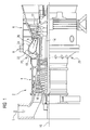
- FIG. 1 a gas turbine plant 2 is shown in a partially sectioned side view. This comprises a compressor 4, a gas turbine 6 and an incinerator 8. In the compressor 4 and in the gas turbine 6, compressor blades 10 and turbine blades 12 are arranged on a common shaft 14, which is also called turbine rotor is and is rotatably mounted about a central axis 16.
- the incinerator 8 comprises an air duct 18 and a number of burners 20, which open into a combustion chamber 22, which in turn opens into the gas turbine 6.
- the combustion chamber 22 is formed in the present embodiment as an annular combustion chamber, i. it extends annularly around the turbine runner 14 around.
- ambient air L is sucked in via the compressor 4, compressed to a higher pressure and discharged into the combustion plant 8 as so-called compressor air.
- the compressor air enters the burner 20 and is mixed with a fuel supplied to the burner 20 and burned in the combustion chamber 22.
- the size of the supplied fuel mass flows can be influenced in this case via one or more, not shown adjustment valves.
- the combustion exhaust gases produced during combustion form a working medium A, which is fed to the turbine 6, where it transfers momentum to the rotor blades 12 under relaxation and cooling, thus causing the turbine rotor 14 to rotate.
- the rotating turbine rotor 14 on the one hand, drives the compressor 4 and, on the other hand, is coupled to a consumer (not shown), for example with an electric generator for generating electricity.
- the gas turbine plant 2 is provided with a device 24 for measuring thermoacoustic oscillations, which in this embodiment is arranged on a wall 26 of the combustion chamber 22.
- the exact structure of the device 24 is in FIG. 2 shown.
- the device 24 comprises a pressure sensor 28, which is arranged on a wall 30 of an acoustic filter 32.
- a Helmholtz resonator in the interior of a volume V is limited.
- the resonator 32 has a neck 34 which is passed through the wall 26.
- an opening 36 is provided, is guided by the coolant, in particular cooling air, in the resonator 32.
- the vibrations occurring in the combustion system 8 during operation of the gas turbine plant 2 are detected in particular continuously and output to a control unit 38.
- the resonator 32 is designed such that it amplifies vibrations in a predetermined frequency bandwidth, so that these vibrations are filtered out in the evaluation of the measurement signal. This is done by tuning the volume V of the resonator 32 with a frequency range representing a stability limit or buzzing limit in the combustion in the gas turbine plant 2.
- the control unit 38 controls an adjusting device, not shown here, in such a way that a flow parameter of the gas turbine plant 2, e.g. an air and / or fuel supply, is changed to avoid exceeding the hum limit.
- the adjusting device may comprise, for example, the adjustment valves already mentioned in relation to the supplied fuel.
- the resonator 32 is provided according to the present embodiment exclusively for filtering out the predetermined frequency bandwidth and has a volume of about 4 liters.
- the function of the resonator 32 can also be extended by the resonator 32 serves as a damper of the thermoacoustic oscillations in the incinerator 8, which, however, requires an increase in the volume V of the resonator 32.
- the wall 30 is formed in the manner of a piston and in Direction of the arrow 40 longitudinally displaceable.
- the volume V of the resonator 32 is changed, whereby the bandwidth of the frequencies filtered out by the resonator likewise changes.
- the volume V can be adapted in a particularly simple manner to the operational thermoacoustic disturbances to allow their early detection.
- a change in the volume V is also possible by optionally also the resonator neck 34 is also displaced in the direction of arrow 40.
- only one acoustic filter 32 with an associated pressure sensor 28 is provided.
- a plurality of devices 24 are arranged in the manner of an array, the acoustic filters 32 are adapted to filter out sound vibrations of different frequency bandwidths.
- the acoustic filter 32 is disposed on the wall 26 of the combustion chamber 22.
- the device 24 is arranged in the air supply passage 18 and / or on a burner 20.
Landscapes
- Engineering & Computer Science (AREA)
- Chemical & Material Sciences (AREA)
- Combustion & Propulsion (AREA)
- Mechanical Engineering (AREA)
- General Engineering & Computer Science (AREA)
- Measurement Of Mechanical Vibrations Or Ultrasonic Waves (AREA)
- Investigating Or Analyzing Materials By The Use Of Ultrasonic Waves (AREA)
Abstract
Description
Die vorliegende Erfindung betrifft eine Vorrichtung und ein Verfahren zur Messung von Schallschwingungen bei einer Fluidströmung, insbesondere zur Messung von thermoakustischen Schallschwingungen in einer Verbrennungsanlage einer Gasturbine. Die Erfindung betrifft weiterhin eine Gasturbinenanlage mit einer solchen Vorrichtung zur Messung von thermoakustischen Schwingungen.The present invention relates to an apparatus and a method for measuring sound vibrations in a fluid flow, in particular for measuring thermoacoustic sound vibrations in a combustion system of a gas turbine. The invention further relates to a gas turbine plant with such a device for measuring thermoacoustic oscillations.
Eine Gasturbinenanlage ist eine Strömungsmaschine, die in der Regel einen Verdichter, eine Verbrennungsanlage sowie eine Turbine umfasst. Im Verdichter erfolgt ein Verdichten von angesaugter Luft, welcher Luft anschließend ein Brennstoff beigemischt wird. Die Verbrennungsanlage umfasst ihrerseits drei Teile: Eine Luftzuführungspassage, die Brenner und die Brennkammer. Die Luftzuführungspassage ist der Raum stromaufwärts der Brenner, in dem die durch den Verdichter komprimierte Luft strömt, bevor sie die Brenner erreicht hat. Durch die Brenner wird der Brennstoff eingespritzt. Die Brenner münden in die Brennkammer, in der die Verbrennung des Gemisches aus komprimierter Luft und Brennstoff stattfindet. Die Verbrennungsabgase werden anschließend der Gasturbine zugeführt, in der den Verbrennungsabgasen thermische Energie entzogen und in mechanische Arbeit umgewandelt wird. Die mechanische Arbeit wird einerseits zum Antreiben des Verdichters und andererseits zum Antreiben eines Verbrauchers, beispielsweise eines Generators zum Erzeugen von Strom, eingesetzt.A gas turbine plant is a turbomachine, which usually comprises a compressor, an incinerator and a turbine. In the compressor, there is a compression of sucked air, which air is then admixed with a fuel. The incinerator comprises three parts: an air supply passage, the burners and the combustion chamber. The air supply passage is the space upstream of the burners in which the air compressed by the compressor flows before it reaches the burners. The fuel is injected through the burners. The burners open into the combustion chamber, in which the combustion of the mixture of compressed air and fuel takes place. The combustion exhaust gases are then fed to the gas turbine, in which the combustion exhaust gases are deprived of thermal energy and converted into mechanical work. The mechanical work is used on the one hand to drive the compressor and on the other hand to drive a consumer, for example a generator for generating electricity.
Bei der Verbrennung in der Brennkammer ist darauf zu achten, dass eine stabile Flamme vorliegt. Instabilitäten der Flamme treffen insbesondere aufgrund von resonanten Verbrennungsschwingungen im Verbrennungsabgas auf und können einerseits zu einem erhöhten Schadstoffausstoß führen und andererseits Schwingungen und Vibrationen der Brennkammer verursachen, die ab einer bestimmten Frequenz - weiterhin Stabilitätsgrenze oder Brummgrenze genannt - die Lebensdauer der Brennkammer herabsetzen und die Wartungsintervalle verkürzen. Derartige Verbrennungsschwingungen in der Brennkammer, die aufgrund thermischer oder akustischer Störungen auftreten, werden weiterhin als thermoakustische Schwingungen bezeichnet.When burning in the combustion chamber, make sure that there is a stable flame. Instabilities of the flame in particular due to resonant combustion vibrations in the combustion exhaust gas and can lead to an increased pollutant emissions on the one hand and on the other hand Vibrations and vibrations of the combustion chamber cause, from a certain frequency - still called stability limit or hum limit - reduce the life of the combustion chamber and shorten the maintenance intervals. Such combustion oscillations in the combustion chamber, which occur due to thermal or acoustic disturbances, are further referred to as thermoacoustic oscillations.
Aus dem Stand der Technik sind Dämpfer zu entnehmen, die aufgrund ihres vorgegebenen Volumens in der Lage sind, bestimmte Schwingungsfrequenzen in der Brennkammer effektiv zu dämpfen. Beispielsweise ist in der Offenlegungsschrift
Der vorliegenden Erfindung liegt die Aufgabe zugrunde, ein frühzeitiges Erkennen von störenden Schallschwingungen bei einer Fluidströmung zu ermöglichen.The present invention has for its object to enable early detection of disturbing sound vibrations in a fluid flow.
Die Aufgabe wird erfindungsgemäß gelöst durch eine Vorrichtung zur Messung von Schallschwingungen bei einer Fluidströmung, insbesondere zur Messung von thermoakustischen Schwingungen in einer Verbrennungsanlage einer Gasturbinenanlage, mit einem akustischen Filter zum Verstärken bzw. Ausfiltern von Schallschwingungen einer vorgegebenen Frequenzbandbreite und einem dem akustischen Filter nachgeschalteten Drucksensor zum Erfassen und Ausgeben der Schallschwingungen.The object is achieved by a device for measuring sound vibrations in a fluid flow, in particular for measuring thermoacoustic oscillations in a combustion system of a gas turbine plant, with an acoustic filter for amplifying or filtering of sound vibrations of a predetermined frequency bandwidth and the acoustic filter downstream pressure sensor for Capture and output the sound vibrations.
Die Erfindung basiert auf der Überlegung, dass ein frühzeitiges Erkennen von Störschwingungen möglich ist, indem durch kontinuierliche Druckmessungen oder Druckmessungen in vorgegebenen Zeitintervallen die Druckschwankungen im Strömungssystem überwacht werden. Der akustische Filter ist dafür nach Art eines aktiven Filters ausgebildet, um Schwingungen in einer vorgegebenen Frequenzbandbreite, insbesondere Schwingungen im Bereich einer Stabilitäts- oder Brummgrenze des Systems zu verstärken, damit mittels des Drucksensors ein besonders klares Messsignal erfasst wird. Es werden hierbei Frequenzen einer größeren Bandbreite gemessen, als die für die der akustische Filter kalibriert ist. Der akustische Filter ist dabei bevorzugt derart ausgebildet, dass er für ein breiteres Frequenzbereich durchlässig ist, jedoch die Schwingungen in der vorgegebenen Frequenzbandbreite deutlich verstärkt sind. Der akustische Filter ist also dafür vorgesehen, eine kleinere Frequenzbandbreite, die die Brummgrenze angibt und somit für die Stabilität des Strömungssystems wesentlich ist, auszufiltern. Beim Annähren an die Brummgrenze wird hierdurch ein besonders klares Messsignal mit einem hohen Signal-Rausch-Verhältnis ermittelt.The invention is based on the consideration that early detection of spurious vibrations is possible by monitoring the pressure fluctuations in the flow system by means of continuous pressure measurements or pressure measurements at predetermined time intervals. The acoustic filter is designed in the manner of an active filter to vibrations in one predetermined frequency bandwidth, in particular to increase vibrations in the range of a stability or humming of the system, so that by means of the pressure sensor, a particularly clear measurement signal is detected. In this case, frequencies of a greater bandwidth are measured than those for which the acoustic filter is calibrated. The acoustic filter is preferably designed such that it is permeable to a wider frequency range, but the vibrations in the predetermined frequency bandwidth are significantly enhanced. The acoustic filter is thus designed to filter out a smaller frequency bandwidth, which indicates the hum limit and thus is essential for the stability of the flow system. When approaching the hum limit, this results in a particularly clear measurement signal with a high signal-to-noise ratio.
Die Vorrichtung kann nach einer entsprechenden Kalibrierung bei unterschiedlichen Strömungssystemen eingesetzt werden. Insbesondere ist die Vorrichtung zur Messung von thermoakustischen Schwingungen in einer Verbrennungsanlage in einer Gasturbine geeignet. Dank dem gezielten Herausfiltern der Schallschwingungen mit einer Frequenz, welche die Brummgrenze angibt, erfolgt bei der Auswertung des Messsignals ein frühes Erkennen von Flammeninstabilitäten, so dass rechtzeitig Maßnahmen zur Stabilisierung des Verbrennungsprozesses eingeleitet werden können und bevorzugt auch werden.The device can be used after a corresponding calibration in different flow systems. In particular, the device is suitable for measuring thermoacoustic oscillations in an incinerator in a gas turbine. Thanks to the targeted filtering out of the sound vibrations with a frequency which indicates the hum limit, an early detection of flame instabilities takes place in the evaluation of the measurement signal, so that timely measures to stabilize the combustion process can be initiated and preferred.
Bevorzugt ist der akustische Filter ein Resonator, insbesondere ein Helmholz-Resonator. Resonatoren bieten viele Möglichkeiten bei ihrer Konstruktion und spielen heutzutage eine wichtige Rolle sowohl in der Akustik als auch in der Hochfrequenztechnik, wo sie als Filter auch für sehr hohe Frequenzen eingesetzt werden können.Preferably, the acoustic filter is a resonator, in particular a Helmholz resonator. Resonators offer many design possibilities and play an important role in both acoustics and high-frequency technology, where they can be used as filters for very high frequencies.
Weiterhin bevorzugt ist der Resonator zum Verstärken unterschiedlicher Frequenzbandbreiten einstellbar. Hierdurch ist die Frequenzbandbreite, die durch den Resonator verstärkt wird, auf einfache Weise an das thermoakustische Verhalten des Strömungssystems anpassbar. Zum Herausfiltern des Messsignals in einer großen Frequenzbandbreite ist hierbei kein Austausch von Resonatoren erforderlich. Gleichzeitig entfällt durch die Verstellbarkeit des Resonators die Notwendigkeit, für unterschiedliche Resonanzfrequenzen unterschiedlich konfigurierte akustische Filter herzustellen und bereit zu halten.Further preferably, the resonator for amplifying different frequency bandwidths is adjustable. As a result, the frequency bandwidth that is amplified by the resonator, in a simple manner to the thermoacoustic behavior adaptable to the flow system. To filter out the measurement signal in a large frequency bandwidth no exchange of resonators is required here. At the same time eliminated by the adjustability of the resonator, the need for different resonant frequencies differently configured acoustic filter to produce and keep ready.
Vorzugsweise ist wenigstens ein Teil einer Wandung des Resonators zur Einstellung eines Resonatorvolumens ortsveränderlich. Hierdurch liegt eine konstruktiv besonders einfache Realisierung des verstellbaren Resonators vor, durch die das Resonatorvolumen und somit die Resonatorfrequenz beeinflusst werden kann. Außerdem ist eine genaue Justage und insbesondere eine kontinuierliche Anpassung des Resonatorvolumens an die Betriebsanforderungen möglich.Preferably, at least a part of a wall of the resonator for adjusting a resonator volume is spatially variable. This results in a structurally particularly simple implementation of the adjustable resonator, by which the resonator volume and thus the resonator frequency can be influenced. In addition, a precise adjustment and in particular a continuous adjustment of the resonator volume to the operating requirements is possible.
Gemäß einer bevorzugten Ausführungsform ist der ortsveränderliche Teil der Wandung als Kolben ausgeführt. Der Kolben kann auf einfache Weise in Längsrichtung verschoben werden, um das Volumen des Resonators genau einzustellen.According to a preferred embodiment, the movable part of the wall is designed as a piston. The piston can easily be displaced longitudinally to precisely adjust the volume of the resonator.
Gemäß einer alternativen Ausführungsform ist der ortsveränderliche Teil der Wandung nach Art eines längsverschieblichen Halses des Resonators ausgeführt. Der Hals des Resonators kann ebenfalls ohne einen großen technischen Aufwand in das Resonatorvolumen hinein oder heraus verschoben werden, wodurch sich das Resonatorvolumen ändert.According to an alternative embodiment, the movable part of the wall is designed in the manner of a longitudinally displaceable neck of the resonator. The neck of the resonator can likewise be moved into or out of the resonator volume without great technical effort, as a result of which the resonator volume changes.
Nach einer bevorzugten Variante ist an einer Wandung des Resonators wenigstens eine Öffnung zur Zuführung von Kühlmittel in den Resonator vorgesehen. Die Zuführung von Kühlmittel ermöglicht einen dauerhaft störungsfreien Betrieb des Resonators bei seinem Einsatz bei sehr hohen Temperaturen, wie z.B. in der Brennkammer einer Gasturbinenanlage.According to a preferred variant, at least one opening for supplying coolant into the resonator is provided on a wall of the resonator. The supply of coolant allows for permanent trouble-free operation of the resonator when used at very high temperatures, e.g. in the combustion chamber of a gas turbine plant.
Gemäß einer bevorzugten Ausgestaltung ist der Resonator ausschließlich zum Verstärken einer vorgegebenen, gemessenen Frequenzbandbreite vorgesehen und weist ein Volumen von weniger als 5 Liter auf. Da die Funktion des Resonators lediglich auf seinen Einsatz als akustischen Filter eingeschränkt ist, kann der Resonator deutlich kleiner dimensioniert werden als die aus dem Stand der Technik bekannten Resonatoren, die zum Dämpfen der thermoakustischen Schwingungen verwendet werden. Zum Ausfiltern einer vorgegebenen Frequenzbandbreite reicht in der Regel ein einziger Resonator aus, dessen Volumen 5 Liter nicht übersteigt. Möglich ist auch, mehrere kleine Resonatoren einzusetzen, deren Gesamtvolumen ebenfalls in der Größenordnung von 5 Liter ist. Somit wäre eine sehr Platz sparende und kostengünstige Realisierung der Vorrichtung gegeben.According to a preferred embodiment, the resonator is exclusively for amplifying a predetermined, measured Frequency bandwidth provided and has a volume of less than 5 liters. Since the function of the resonator is limited only to its use as an acoustic filter, the resonator can be dimensioned significantly smaller than those known from the prior art resonators, which are used for damping the thermoacoustic oscillations. To filter out a given frequency bandwidth is usually sufficient, a single resonator whose volume does not exceed 5 liters. It is also possible to use several small resonators whose total volume is also in the order of 5 liters. Thus, a very space-saving and cost-effective implementation of the device would be given.
Gemäß einer alternativen Ausführungsvariante ist der Resonator als Dämpfer der Schallschwingungen einsetzbar. Eine Erweiterung der Funktion des akustischen Filters, bei der er außerdem als Dämpfer eingesetzt wird, erfordert eine entsprechende Vergrößerung des Volumens des Resonators. Zur Erfüllung dieser erweiterten Funktion kann ein Resonator herangezogen werden, der sowohl ein festes als auch ein veränderliches Volumen aufweisen kann, welches jedoch stets mit der Brummgrenze des Strömungssystems abgestimmt ist. Somit ist der Resonator in der Lage, die Störschwingungen nicht nur zu dämpfen, wie bisher bekannt, sondern sie auch bei den Messungen mittels des Drucksensors herauszufiltern.According to an alternative embodiment, the resonator can be used as a damper of the sound vibrations. An extension of the function of the acoustic filter, in which it is also used as a damper, requires a corresponding increase in the volume of the resonator. To fulfill this extended function, it is possible to use a resonator which can have both a fixed volume and a variable volume, which, however, is always matched to the flow limit of the flow system. Thus, the resonator is not only able to dampen the spurious, as previously known, but also to filter it out in the measurements by means of the pressure sensor.
Vorteilhafterweise sind mehrere akustische Filter vorgesehen, die zum Verstärken von Schallschwingungen unterschiedlicher Frequenzbandbreiten eingestellt sind. Besonders vorteilhaft ist der Einsatz einer solchen Konfiguration in Kombination mit akustischen Filtern, deren Volumen unveränderbar ist, so dass jeder Filter zum Ausfiltern lediglich einer vorgegebenen Frequenzbandbreite ausgebildet ist. Durch die Verwendung von mehreren akustischen Filtern, die Schallschwingungen unterschiedlicher Frequenzbandbreiten ausfiltern können, kann ein besonders breiter Frequenzbereich abgedeckt werden. Eine Gruppierung von mehreren akustischen Filtern in einem Array ist auch möglich, wenn die auszufilternden Frequenzbandbreiten einiger oder aller akustischer Filter einstellbar sind.Advantageously, a plurality of acoustic filters are provided, which are set for amplifying sound vibrations of different frequency bandwidths. Particularly advantageous is the use of such a configuration in combination with acoustic filters whose volume is unchangeable, so that each filter is designed to filter only a predetermined frequency bandwidth. By using several acoustic filters that can filter out sound vibrations of different frequency bandwidths, a particularly wide frequency range can be covered. A grouping of multiple acoustic filters in an array is also possible if the frequency bandwidths to be filtered out of some or all of the acoustic filters can be set.
Weiterhin von Vorteil ist, dass eine Steuereinheit zum Auswerten des Messsignals des Drucksensors sowie eine von der Steuereinheit angesteuerten Stelleinrichtung zum Beeinflussen mindestens eines Strömungsparameters der Fluidströmung, insbesondere einer Luft- und/oder Brennstoffzufuhr, in Abhängigkeit von dem Messsignal vorgesehen sind. Wie bereits erläutert, wird durch Messungen der Druckschwankung im Strömungssystem eine Annäherung an die Brummgrenze festgestellt. Als entsprechende Reaktion auf eine solche Annäherung wird die Stelleinrichtung derart angesteuert, dass eine Änderung der Gasturbinenleistung bewirkt wird. Beispielsweise wird ein absoluter Wert der Luftzufuhr und/oder der Brennstoffzufuhr und/oder des Verhältnisses von Luftzufuhr zur Brennstoffzufuhr derart eingestellt, dass ein Überschreiten der Brummgrenze verhindert wird.Furthermore, it is advantageous that a control unit for evaluating the measurement signal of the pressure sensor and a control unit controlled by the control unit for influencing at least one flow parameter of the fluid flow, in particular an air and / or fuel supply, are provided in response to the measurement signal. As already explained, measurements of the pressure fluctuation in the flow system determine an approach to the hum limit. As a corresponding reaction to such an approach, the adjusting device is controlled such that a change in the gas turbine power is effected. For example, an absolute value of the air supply and / or the fuel supply and / or the ratio of air supply to the fuel supply is set such that exceeding the hum limit is prevented.
Die Aufgabe wird weiterhin erfindungsgemäß gelöst durch eine Gasturbinenanlage mit wenigstens einer Verbrennungsanlage, umfassend eine solche Vorrichtung zur Messung thermoakustischer Schwingungen in der Verbrennungsanlage. Hierbei kann die Vorrichtung in unterschiedlichen Bereichen der Verbrennungsanlage angeordnet sein. Gemäß einer bevorzugten Variante ist die Vorrichtung in einer Luftzuführungspassage der Verbrennungsanlage angeordnet. Gemäß einer weiteren alternativen Variante ist die Vorrichtung an einer Wand einer Brennkammer der Verbrennungsanlage angeordnet. Gemäß einer dritten alternativen Variante ist die Vorrichtung an einem Brenner oder im Bereich eines Brenners der Verbrennungsanlage angeordnet.The object is further achieved according to the invention by a gas turbine plant with at least one incinerator, comprising such a device for measuring thermoacoustic oscillations in the incinerator. In this case, the device can be arranged in different areas of the incinerator. According to a preferred variant, the device is arranged in an air supply passage of the incinerator. According to a further alternative variant, the device is arranged on a wall of a combustion chamber of the incinerator. According to a third alternative variant, the device is arranged on a burner or in the region of a burner of the incinerator.
Die Aufgabe wird weiterhin erfindungsgemäß gelöst durch ein Verfahren zur Messung von Schallschwingungen bei einer Fluidströmung, insbesondere zur Messung von thermoakustischen Schwingungen in einer Verbrennungsanlage einer Gasturbinenanlage, bei dem die Schallschwingungen mittels eines akustischen Filters, der zur Verstärkung des Messsignals innerhalb einer vorgegebenen Frequenzbandbreite vorgesehen ist, und eines Drucksensors erfasst und ausgegeben werden. Die im Hinblick auf die Vorrichtung aufgeführten Vorteile und bevorzugten Ausführungsformen lassen sich sinngemäß auf das Verfahren übertragen.The object is further achieved according to the invention by a method for measuring sound vibrations in a fluid flow, in particular for measuring thermoacoustic oscillations in a combustion system of a gas turbine plant, wherein the sound vibrations are detected and output by means of an acoustic filter provided for amplifying the measurement signal within a predetermined frequency bandwidth and a pressure sensor. The advantages and preferred embodiments listed with regard to the device can be transferred analogously to the method.
In Abhängigkeit vom Messsignal wird eine Annäherung an die Stabilitätsgrenze des Strömungssystems detektiert und es werden frühzeitig Maßnahmen ergriffen, um die Stabilität des Strömungssystems beizubehalten. Als entsprechende Maßnahmen wird vorzugsweise ein Strömungsparameter der Fluidströmung, insbesondere eine Luft- und/oder Brennstoffzufuhr der Gasturbinenanlage - wenn es sich beim Strömungssystem um eine Gasturbinenanlage handelt - in Abhängigkeit vom Messsignal eingestellt.Depending on the measurement signal, an approach to the stability limit of the flow system is detected and early measures are taken to maintain the stability of the flow system. As appropriate measures is preferably a flow parameter of the fluid flow, in particular an air and / or fuel supply of the gas turbine plant - if the flow system is a gas turbine plant - set depending on the measurement signal.
Ein Ausführungsbeispiel der Erfindung wird anhand einer Zeichnung näher erläutert. Hierin zeigen:
- FIG 1
- schematisch eine Gasturbinenanlage mit einer Verbrennungsanlage, und
- FIG 2
- einen Schnitt durch eine Vorrichtung zur Messung von thermoakustischen Schwingungen in der Verbrennungsanlage der Gasturbinenanlage gemäß
FIG 1 .
- FIG. 1
- schematically a gas turbine plant with an incinerator, and
- FIG. 2
- a section through a device for measuring thermoacoustic vibrations in the combustion system of the gas turbine plant according to
FIG. 1 ,
In den Figuren sind gleich wirkende Teile mit den gleichen Bezugszeichen versehen.In the figures, like-acting parts are provided with the same reference numerals.
In
Die Verbrennungsanlage 8 umfasst einen Luftkanal 18 und eine Anzahl von Brennern 20, die in eine Brennkammer 22 münden, welche wiederum in die Gasturbine 6 mündet. Die Brennkammer 22 ist im vorliegenden Ausführungsbeispiel als Ringbrennkammer ausgebildet, d.h. sie erstreckt sich ringförmig um den Turbinenläufer 14 herum.The incinerator 8 comprises an
Im Betrieb der Gasturbinenanlage 2 wird über den Verdichter 4 Umgebungsluft L eingesaugt, auf einen höheren Druck verdichtet und in die Verbrennungsanlage 8 als so genannte Verdichterluft ausgegeben. In der Verbrennungsanlage 8 tritt die Verdichterluft in den Brenner 20 ein und wird mit einem dem Brenner 20 zugeführten Brennstoff vermischt und in der Brennkammer 22 verbrannt. Die Größe der zugeführten Brennstoffmassenströme lässt sich hierbei über ein oder mehrere, nicht näher gezeigte Einstellventile beeinflussen.During operation of the
Die bei der Verbrennung entstehenden Verbrennungsabgase bilden ein Arbeitsmedium A, welches der Turbine 6 zugeleitet wird und dort unter Entspannung und Abkühlung Impuls auf die Laufschaufeln 12 überträgt und so den Turbinenläufer 14 in Rotation versetzt. Der rotierende Turbinenläufer 14 treibt einerseits den Verdichter 4 an und ist andererseits mit einem Verbraucher (nicht dargestellt) gekoppelt, beispielsweise mit einem elektrischen Generator zum Erzeugen von Strom.The combustion exhaust gases produced during combustion form a working medium A, which is fed to the turbine 6, where it transfers momentum to the
Um Instabilitäten der Flamme in der Brennkammer 22 zu vermeiden, ist die Gasturbinenanlage 2 mit einer Vorrichtung 24 zur Messung von thermoakustischen Schwingungen versehen, die in diesem Ausführungsbeispiel an einer Wand 26 der Verbrennungskammer 22 angeordnet ist.In order to avoid instabilities of the flame in the
Der genaue Aufbau der Vorrichtung 24 ist in
Mittels des Drucksensors 28 werden die in der Verbrennungsanlage 8 im Betrieb der Gasturbinenanlage 2 auftretenden Schwingungen insbesondere kontinuierlich erfasst und einer Steuereinheit 38 ausgegeben. Der Resonator 32 ist derart ausgebildet, dass er Schwingungen in einer vorgegebenen Frequenzbandbreite verstärkt, so dass diese Schwingungen bei der Auswertung des Messsignals herausgefiltert sind. Dies erfolgt durch ein Abstimmen des Volumens V des Resonators 32 mit einem Frequenzbereich, der eine Stabilitätsgrenze oder Brummgrenze bei der Verbrennung in der Gasturbinenanlage 2 darstellt. Beim Feststellen einer Annäherung der Schwingungsfrequenz an die Brummgrenze steuert die Steuereinheit 38 eine hier nicht gezeigte Stelleinrichtung derart an, dass ein Strömungsparameter der Gasturbinenanlage 2, z.B. eine Luft- und/oder Brennstoffzufuhr, geändert wird, um ein Überschreiten der Brummgrenze zu vermeiden. Die Stelleinrichtung kann beispielsweise die in Bezug auf den zugeführten Brennstoff bereits angeführten Einstellventile umfassen.By means of the
Der Resonator 32 ist gemäß dem vorliegenden Ausführungsbeispiel ausschließlich zum Herausfiltern der vorgegebenen Frequenzbandbreite vorgesehen und weist ein Volumen von etwa 4 Liter auf. Die Funktion des Resonators 32 kann außerdem erweitert werden, indem der Resonator 32 als ein Dämpfer der thermoakustischen Schwingungen in der Verbrennungsanlage 8 dient, was allerdings eine Vergrößerung des Volumens V des Resonators 32 voraussetzt.The
Gemäß der in
In dem vorliegenden Ausführungsbeispiel ist lediglich ein akustischer Filter 32 mit einem zugeordneten Drucksensor 28 vorgesehen. In einer alternativen, nicht gezeigten Ausgestaltung sind mehrere Vorrichtungen 24 nach Art eines Arrays angeordnet, deren akustische Filter 32 dafür ausgebildet sind, Schallschwingungen unterschiedlicher Frequenzbandbreiten auszufiltern.In the present embodiment, only one
In
Claims (17)
wobei der akustische Filter (32) ein Resonator, insbesondere ein Helmholz-Resonator ist.Device (24) according to claim 1,
wherein the acoustic filter (32) is a resonator, in particular a Helmholz resonator.
wobei der Resonator (32) zum Verstärken von Schwingungen unterschiedlicher Frequenzbandbreiten einstellbar ist.Device (24) according to claim 1 or 2,
wherein the resonator (32) is adjustable for amplifying vibrations of different frequency bandwidths.
wobei wenigstens ein Teil einer Wandung des Resonators (32) zur Einstellung eines Resonatorvolumens (V) ortsveränderlich ist.Device (24) according to claims 2 and 3,
wherein at least a part of a wall of the resonator (32) for adjusting a resonator volume (V) is spatially variable.
wobei der ortsveränderliche Teil der Wandung als Kolben (30) ausgeführt ist.Device (24) according to claim 4,
wherein the mobile part of the wall is designed as a piston (30).
wobei der ortsveränderliche Teil der Wandung nach Art eines längsverschieblichen Halses (34) des Resonators (32) ausgeführt ist.Device (24) according to claim 4,
wherein the movable part of the wall is designed in the manner of a longitudinally displaceable neck (34) of the resonator (32).
wobei an einer Wandung des Resonators (32) wenigstens eine Öffnung (36) zur Zuführung von Kühlmittel in den Resonator (32) vorgesehen ist.Device (24) according to one of claims 2 to 6,
wherein on a wall of the resonator (32) at least one opening (36) for supplying coolant into the resonator (32) is provided.
wobei der Resonator (32) ausschließlich zum Ausfiltern von Schwingungen einer vorgegebenen Frequenzbandbreite vorgesehen ist und ein Volumen (V) von weniger als 5 1 aufweist.Device (24) according to one of claims 2 to 7,
wherein the resonator (32) is provided exclusively for filtering out vibrations of a predetermined frequency bandwidth and has a volume (V) of less than 5 1.
wobei der Resonator (32) als ein Dämpfer für die Schallschwingungen ausgebildet ist.Device (24) according to one of claims 2 to 7,
wherein the resonator (32) is formed as a damper for the sound vibrations.
wobei mehrere akustische Filter (32) vorgesehen sind, die zum Verstärken von Schallschwingungen unterschiedlicher Frequenzbandbreiten eingestellt ist.Device (24) according to one of the preceding claims,
wherein a plurality of acoustic filters (32) are provided, which is set for amplifying sound vibrations of different frequency bandwidths.
wobei eine Steuereinheit (38) zum Auswerten eines Messsignals des Drucksensors (28) sowie eine von der Steuereinheit (38) angesteuerte Stelleinrichtung zum Beeinflussen mindestens eines Strömungsparameters der Fluidströmung, insbesondere einer Luft- und/oder Brennstoffzufuhr, in Abhängigkeit von dem Messsignal vorgesehen sind.Device (24) according to one of the preceding claims,
wherein a control unit (38) for evaluating a measurement signal of the pressure sensor (28) and a control unit (38) controlled actuating device for influencing at least one flow parameter of the fluid flow, in particular an air and / or fuel supply, are provided in response to the measurement signal.
wobei die Vorrichtung (24) in einer Luftzuführungspassage (18) der Verbrennungsanlage (8) angeordnet ist.Gas turbine plant (2) according to claim 12,
wherein the device (24) is arranged in an air supply passage (18) of the incinerator (8).
wobei die Vorrichtung (24) an einer Wand (26) einer Brennkammer (22) der Verbrennungsanlage (8) angeordnet ist.Gas turbine plant (2) according to claim 12,
wherein the device (24) is arranged on a wall (26) of a combustion chamber (22) of the incinerator (8).
wobei die Vorrichtung (24) an einem Brenner (20) der Verbrennungsanlage (20) angeordnet ist.Gas turbine plant according to claim 12,
wherein the device (24) is arranged on a burner (20) of the incinerator (20).
bei dem ein Strömungsparameter der Fluidströmung, insbesondere eine Luft- und/oder Brennstoffzufuhr der Gasturbinenanlage (2), in Abhängigkeit von einem Messsignal des Drucksensors (28) eingestellt wird.Method according to claim 16,
in which a flow parameter of the fluid flow, in particular an air and / or fuel supply of the gas turbine plant (2), in dependence on a measurement signal of the pressure sensor (28) is set.
Priority Applications (2)
| Application Number | Priority Date | Filing Date | Title |
|---|---|---|---|
| EP07009448A EP1990579A1 (en) | 2007-05-10 | 2007-05-10 | Device and method for measuring acoustic oscillations in the fluid flow and gas turbine facility with such a device |
| PCT/EP2008/055626 WO2008138828A1 (en) | 2007-05-10 | 2008-05-07 | Device and method for measuring acoustic vibrations in a fluid flow and a gas turbine installation with such a device |
Applications Claiming Priority (1)
| Application Number | Priority Date | Filing Date | Title |
|---|---|---|---|
| EP07009448A EP1990579A1 (en) | 2007-05-10 | 2007-05-10 | Device and method for measuring acoustic oscillations in the fluid flow and gas turbine facility with such a device |
Publications (1)
| Publication Number | Publication Date |
|---|---|
| EP1990579A1 true EP1990579A1 (en) | 2008-11-12 |
Family
ID=38567140
Family Applications (1)
| Application Number | Title | Priority Date | Filing Date |
|---|---|---|---|
| EP07009448A Withdrawn EP1990579A1 (en) | 2007-05-10 | 2007-05-10 | Device and method for measuring acoustic oscillations in the fluid flow and gas turbine facility with such a device |
Country Status (2)
| Country | Link |
|---|---|
| EP (1) | EP1990579A1 (en) |
| WO (1) | WO2008138828A1 (en) |
Cited By (2)
| Publication number | Priority date | Publication date | Assignee | Title |
|---|---|---|---|---|
| WO2010149420A1 (en) * | 2009-06-26 | 2010-12-29 | Siemens Aktiengesellschaft | Combustion chamber arrangement for damping thermo-acoustic oscillations, gas turbine and method of operating such a gas turbine |
| US11092083B2 (en) | 2017-02-10 | 2021-08-17 | General Electric Company | Pressure sensor assembly for a turbine engine |
Families Citing this family (1)
| Publication number | Priority date | Publication date | Assignee | Title |
|---|---|---|---|---|
| US9063033B2 (en) * | 2013-03-12 | 2015-06-23 | Solar Turbines Incorporated | Sensor housing for use with gas turbine engines |
Citations (5)
| Publication number | Priority date | Publication date | Assignee | Title |
|---|---|---|---|---|
| US5894823A (en) * | 1996-12-13 | 1999-04-20 | Hyundai Motor Company | Variable suction resonator system for internal combustion engines |
| EP1158247A2 (en) * | 2000-05-26 | 2001-11-28 | ALSTOM Power N.V. | Apparatus to reduce acoustic vibrations in a combustion chamber |
| US6464489B1 (en) * | 1997-11-24 | 2002-10-15 | Alstom | Method and apparatus for controlling thermoacoustic vibrations in a combustion system |
| US20030211432A1 (en) * | 2002-03-27 | 2003-11-13 | Gutmark Ephraim J. | Method and device for the control of thermoacoustic instabilities or oscillations in a combustion system |
| US20040173175A1 (en) * | 2003-03-04 | 2004-09-09 | Kostun John D. | Helmholtz resonator |
-
2007
- 2007-05-10 EP EP07009448A patent/EP1990579A1/en not_active Withdrawn
-
2008
- 2008-05-07 WO PCT/EP2008/055626 patent/WO2008138828A1/en active Application Filing
Patent Citations (5)
| Publication number | Priority date | Publication date | Assignee | Title |
|---|---|---|---|---|
| US5894823A (en) * | 1996-12-13 | 1999-04-20 | Hyundai Motor Company | Variable suction resonator system for internal combustion engines |
| US6464489B1 (en) * | 1997-11-24 | 2002-10-15 | Alstom | Method and apparatus for controlling thermoacoustic vibrations in a combustion system |
| EP1158247A2 (en) * | 2000-05-26 | 2001-11-28 | ALSTOM Power N.V. | Apparatus to reduce acoustic vibrations in a combustion chamber |
| US20030211432A1 (en) * | 2002-03-27 | 2003-11-13 | Gutmark Ephraim J. | Method and device for the control of thermoacoustic instabilities or oscillations in a combustion system |
| US20040173175A1 (en) * | 2003-03-04 | 2004-09-09 | Kostun John D. | Helmholtz resonator |
Cited By (3)
| Publication number | Priority date | Publication date | Assignee | Title |
|---|---|---|---|---|
| WO2010149420A1 (en) * | 2009-06-26 | 2010-12-29 | Siemens Aktiengesellschaft | Combustion chamber arrangement for damping thermo-acoustic oscillations, gas turbine and method of operating such a gas turbine |
| EP2282120A1 (en) * | 2009-06-26 | 2011-02-09 | Siemens Aktiengesellschaft | Combustion chamber assembly for dampening thermoacoustic oscillations, gas turbine and method for operating such a gas turbine |
| US11092083B2 (en) | 2017-02-10 | 2021-08-17 | General Electric Company | Pressure sensor assembly for a turbine engine |
Also Published As
| Publication number | Publication date |
|---|---|
| WO2008138828A1 (en) | 2008-11-20 |
Similar Documents
| Publication | Publication Date | Title |
|---|---|---|
| EP1880141A1 (en) | Process and device for regulating the course of a gas turbine combustion chamber | |
| EP0961906B1 (en) | Method for active attenuation of a combustion oscillation, and use of the method | |
| EP1621811B1 (en) | Operating Method for a Combustion Apparatus | |
| DE4417199C2 (en) | Device for controlling gas turbines | |
| EP1251244B1 (en) | Method for suppressing combustion fluctuations in a gas turbine | |
| DE102009012914A1 (en) | Active pattern factor control for gas turbine engines | |
| DE4339094A1 (en) | Damping of thermal-acoustic vibrations resulting from combustion of fuel | |
| DE19640980B4 (en) | Device for damping thermoacoustic oscillations in a combustion chamber | |
| DE102010037078A1 (en) | Acoustically stiffened gas turbine combustor feeder | |
| WO1993010401A1 (en) | Arrangement for suppressing combustion-caused vibrations in the combustion chamber of a gas turbine system | |
| EP2789914A1 (en) | Method for monitoring the status of a flame | |
| EP1762786A1 (en) | Process and apparatus to dampen thermo-accoustic vibrations, in particular within a gas turbine | |
| DE19928226A1 (en) | Process for suppressing or controlling thermoacoustic vibrations in a combustion system and combustion system for carrying out the process | |
| WO1998012478A1 (en) | Method and device for fuel combustion with air | |
| EP2780635A2 (en) | Combustion chamber for a gas turbine and gas turbine as well as a method | |
| DE4040745A1 (en) | ACTIVE CONTROL OF COMBUSTION-BASED INSTABILITIES | |
| EP1990579A1 (en) | Device and method for measuring acoustic oscillations in the fluid flow and gas turbine facility with such a device | |
| EP1348908A2 (en) | Method and device for controlling thermoacoustic instabilities or vibrations in a combustion system | |
| DE102005011287B4 (en) | Method and an apparatus for operating at least one burner for firing the combustion chamber of a heat engine or gas turbine | |
| EP0969192B1 (en) | Method to equalize the fuel distribution in a gas turbine with several burners | |
| WO2010149420A1 (en) | Combustion chamber arrangement for damping thermo-acoustic oscillations, gas turbine and method of operating such a gas turbine | |
| EP1533569B1 (en) | Method for operating a furnace | |
| EP1649218B1 (en) | Method for reducing nox emissions from a burner assembly, comprising several burners, and burner assembly for carrying out said method | |
| DE102016004977A1 (en) | Method and apparatus for thermal material treatment in a swinging fire reactor | |
| EP1624251A1 (en) | apparatus for reducing thermoacoustic oscillations in combustion chambers with adjustable resonance frequency |
Legal Events
| Date | Code | Title | Description |
|---|---|---|---|
| PUAI | Public reference made under article 153(3) epc to a published international application that has entered the european phase |
Free format text: ORIGINAL CODE: 0009012 |
|
| AK | Designated contracting states |
Kind code of ref document: A1 Designated state(s): AT BE BG CH CY CZ DE DK EE ES FI FR GB GR HU IE IS IT LI LT LU LV MC MT NL PL PT RO SE SI SK TR |
|
| AX | Request for extension of the european patent |
Extension state: AL BA HR MK RS |
|
| AKX | Designation fees paid | ||
| STAA | Information on the status of an ep patent application or granted ep patent |
Free format text: STATUS: THE APPLICATION IS DEEMED TO BE WITHDRAWN |
|
| 18D | Application deemed to be withdrawn |
Effective date: 20090513 |
|
| REG | Reference to a national code |
Ref country code: DE Ref legal event code: 8566 |