EP1962018A1 - Combustion chamber for gas turbine engine - Google Patents
Combustion chamber for gas turbine engine Download PDFInfo
- Publication number
- EP1962018A1 EP1962018A1 EP20080009068 EP08009068A EP1962018A1 EP 1962018 A1 EP1962018 A1 EP 1962018A1 EP 20080009068 EP20080009068 EP 20080009068 EP 08009068 A EP08009068 A EP 08009068A EP 1962018 A1 EP1962018 A1 EP 1962018A1
- Authority
- EP
- European Patent Office
- Prior art keywords
- combustion chamber
- resonators
- tube
- resonator
- helmholtz
- Prior art date
- Legal status (The legal status is an assumption and is not a legal conclusion. Google has not performed a legal analysis and makes no representation as to the accuracy of the status listed.)
- Granted
Links
- 238000002485 combustion reaction Methods 0.000 title claims abstract description 108
- 238000013016 damping Methods 0.000 claims abstract description 24
- 238000004891 communication Methods 0.000 claims abstract description 11
- 238000001816 cooling Methods 0.000 abstract description 12
- 238000011144 upstream manufacturing Methods 0.000 description 3
- 238000013461 design Methods 0.000 description 2
- 238000005553 drilling Methods 0.000 description 2
- 230000010355 oscillation Effects 0.000 description 2
- 238000013459 approach Methods 0.000 description 1
- 230000015572 biosynthetic process Effects 0.000 description 1
- 230000000694 effects Effects 0.000 description 1
- 239000000446 fuel Substances 0.000 description 1
- 238000002347 injection Methods 0.000 description 1
- 239000007924 injection Substances 0.000 description 1
- 238000000034 method Methods 0.000 description 1
- 238000012986 modification Methods 0.000 description 1
- 230000004048 modification Effects 0.000 description 1
- 230000002028 premature Effects 0.000 description 1
- 238000007789 sealing Methods 0.000 description 1
- 230000003068 static effect Effects 0.000 description 1
- 238000005728 strengthening Methods 0.000 description 1
Images

Classifications
-
- F—MECHANICAL ENGINEERING; LIGHTING; HEATING; WEAPONS; BLASTING
- F23—COMBUSTION APPARATUS; COMBUSTION PROCESSES
- F23R—GENERATING COMBUSTION PRODUCTS OF HIGH PRESSURE OR HIGH VELOCITY, e.g. GAS-TURBINE COMBUSTION CHAMBERS
- F23R3/00—Continuous combustion chambers using liquid or gaseous fuel
- F23R3/002—Wall structures
-
- F—MECHANICAL ENGINEERING; LIGHTING; HEATING; WEAPONS; BLASTING
- F23—COMBUSTION APPARATUS; COMBUSTION PROCESSES
- F23M—CASINGS, LININGS, WALLS OR DOORS SPECIALLY ADAPTED FOR COMBUSTION CHAMBERS, e.g. FIREBRIDGES; DEVICES FOR DEFLECTING AIR, FLAMES OR COMBUSTION PRODUCTS IN COMBUSTION CHAMBERS; SAFETY ARRANGEMENTS SPECIALLY ADAPTED FOR COMBUSTION APPARATUS; DETAILS OF COMBUSTION CHAMBERS, NOT OTHERWISE PROVIDED FOR
- F23M20/00—Details of combustion chambers, not otherwise provided for, e.g. means for storing heat from flames
- F23M20/005—Noise absorbing means
-
- F—MECHANICAL ENGINEERING; LIGHTING; HEATING; WEAPONS; BLASTING
- F23—COMBUSTION APPARATUS; COMBUSTION PROCESSES
- F23R—GENERATING COMBUSTION PRODUCTS OF HIGH PRESSURE OR HIGH VELOCITY, e.g. GAS-TURBINE COMBUSTION CHAMBERS
- F23R2900/00—Special features of, or arrangements for continuous combustion chambers; Combustion processes therefor
- F23R2900/00014—Reducing thermo-acoustic vibrations by passive means, e.g. by Helmholtz resonators
Definitions
- This invention relates to combustion chambers for gas turbine engines, and in particular concerns lean burn, low emission combustion chambers having one or more resonator chamber for damping pressure fluctuations in the combustion chamber in use.
- Pressure oscillations in gas turbine engine combustors can be damped by using damping devices such as Helmholtz resonators, preferably in flow communication with the interior of the combustion chamber or the gas flow region surrounding the combustion chamber.
- Helmholtz resonators has been proposed in a number of earlier published patents including for example US-A-5,644,918 where a plurality of resonators are connected to the head end, that is to say the upstream end, of the flame tubes of an industrial gas turbine engine combustor.
- This type of arrangement is particularly suitable for industrial gas turbine engines where there is sufficient space at the head of the combustor to install such damping devices.
- the combustor in a ground based engine application can be made sufficiently strong to support the resonators and the vibration loads generated by the resonators in use. This arrangement is not practicable for use in aero engine applications where space, particularly in the axial direction of the engine, is more limited and component weight is a significant design consideration.
- a combustion chamber for a gas turbine engine comprising an annular region defined by a combustion chamber inner casing and a combustion chamber outer casing; a combustion chamber located in the annular region and comprising at least one Helmholtz resonator having a cavity and a damping tube in flow communication with the interior of the combustion chamber, characterised in that the damping tube extends into the interior of the combustion chamber, and the at least one Helmholtz resonator is supported independently of the combustion chamber by the said combustion chamber inner casing , and the at least one Helmholtz resonator is supported by the combustion chamber inner casing with the at least one Helmholtz resonator positioned on the radially inner side of the combustion chamber and enclosed within a cavity provided between the combustion chamber inner casing and a windage shield on a radially inner side of the said casing.
- a gas turbine engine combustion section including a combustion chamber, a combustion chamber inner casing and a combustion chamber outer casing; the said combustion chamber comprising at least one Helmholtz resonator having a cavity and a damping tube in flow communication with the interior of the combustion chamber, the said at least one resonator being supported with respect to the combustion chamber independently of the combustion chamber by the said combustion chamber inner casing or the said outer casing.
- Supporting the resonator or resonators by the combustion chamber inner casing or outer casing of a gas turbine engine it is possible that no significant strengthening of the combustion chamber, inner casing or outer casing is required. In this way it is possible to support both the weight and the operational loads, static and dynamic, using existing engine structural components in the region of the combustion chamber.
- the combustion chamber is not subject therefore to further loads and therefore may be of a similar weight and dimensions to that of traditional combustors.
- a gas turbine engine combustion section including a combustion chamber and at least a combustion chamber inner casing; the said combustion chamber comprising at least one Helmholtz resonator having a cavity and a damping tube in flow communication with the interior of the combustion chamber, the said at least one resonator being at least partially enclosed within a cavity provided between the said inner casing and a windage shield on a radially inner side of the said casing.
- the resonators are enclosed within the cavity provided between the combustion chamber inner casing and the windage shield.
- the resonators are circumferentially spaced around the combustion chamber.
- a combustion chamber for a gas turbine engine comprising a plurality of Helmholtz resonators each having a cavity and a damping tube in flow communication with the interior of the combustion chamber, the said resonators being circumferentially spaced around the combustion chamber with the respective cavities of diametrically opposed resonators having substantially different volumes.
- This is particularly significant since it can prevent or at least reduce the formation of coupled acoustic nodes in the combustion chamber. In preferred embodiments this can be achieved by positioning the resonators circumferentially around the combustion chamber with the cavities of the respective resonators having successively smaller volumes. In this way it will be understood that the cavity having the largest volume will be positioned next to the cavity having the smallest volume.
- combustion chamber used herein is used interchangeably with the term “combustor” and reference to one include reference to the other.
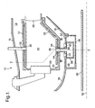
- the combustion section 10 of a gas turbine aero engine is illustrated with the adjacent engine parts omitted for clarity, that is the compressor section upstream of the combustor (to the left of the drawing in Figure 1 ) and the turbine section downstream of the combustion section.
- the combustion section comprises an annular type combustion chamber 12 positioned in an annular region 14 between a combustion chamber outer casing 16, which is part of the engine casing structure and radially outwards of the combustion chamber, and a combustion chamber inner casing 18, also part of the engine structure and positioned radially inwards of the combustion chamber 12.
- the inner casing 16 and outer casing 18 comprise part of the engine casing load bearing structure and the function of these components is well understood by those skilled in the art.
- the combustion chamber 12 is cantilevered at its downstream end from an annular array of nozzle guide vanes 20, one of which is shown in part in the drawing of Figure 1 .
- the combustion chamber may be considered to be a non load bearing component in the sense that it does not support any loads other than the loads acting upon it due to the pressure differential across the walls of the combustion chamber.
- the combustion chamber comprises a continuous heat shield type lining on its radially inner and outer interior surfaces.
- the lining comprises a series of heat resistant tiles 22 which are attached to the interior surface of the radially inner and outer walls of the combustor in a known manner.
- the upstream end of the combustion chamber comprises an annular end wall 24, which includes a series of circumferentially spaced apertures 26 for receiving respective air fuel injection devices 28.
- the radially outer wall of the combustion chamber includes at least one opening 30 for receiving the end of an ignitor 32, which passes through a corresponding aperture in the outer casing 16 on which it is secured.
- the radially inner wall of the combustion chamber is provided with a plurality of circumferentially spaced apertures 34 for receiving the end part of a Helmholtz resonator damping tube 36.
- Each Helmholtz resonator 38 comprises a box like resonator cavity 40 which is in flow communication with the interior of the combustion chamber through the damping tube 36 which extends radially from the resonator cavity 40 into the interior 41 of the combustor.
- the resonator cavity 40 extends circumferentially around part of the circumference of the combustion chamber inner casing 18 on the radially inner side thereof.
- the damping tube 36 extends through a respective aperture in the inner casing 18 in register with the aperture 34 in the combustion chamber inner wall.
- the damping tube has a substantially circular cross section although tubes having cross sections other than circular may be used.
- the Helmholtz resonator 38 is fixed to the inner casing 18 by fixing means 42 in the form of bolts, studs or the like. The resonator 38 is therefore mounted and supported independently of the combustion chamber 12.
- An annular sealing member 44 is provided around the outer periphery of the tube to provide a gas tight seal between the tube and the opening 34.
- the tube provides for limited relative axial movement of the tube with respect to the combustion chamber so that substantially no load is transferred from the resonator tube to the combustion chamber during engine operation.
- each resonator 38 is positioned around the radially inner side of the combustion chamber inner casing 18.
- the resonators are arranged in two groups one including four resonators and the other group including the other three.
- the resonators have different circumferential dimensions such that the volume of the respective cavities 40 of the resonators is different for each resonator.
- This difference in cavity volume has the effect of ensuring each resonator has a different resonator frequency such that the respective resonators 38 compliment one another in the sense that collectively the resonators operate over a wide frequency band to damp pressure oscillations in the combustion chamber over substantially the entire running range of the engine.
- Each resonator has a particularly frequency and the resonator cavities 40 are sized such that the different resonator frequencies do not substantially overlap.
- the resonator cavities are enclosed in an annular cavity 46 defined on one side by the combustion chamber inner casing 18 and along the other side by a windage shield 48, which, in use, functions to reduce windage losses between the box type resonators 38 and the high pressure engine shaft 50 when it rotates about the engine axis 52.
- the windage shield 48 extends annularly around the inner casing 18 to enclose all seven resonators 38 in a streamlined manner so that windage losses are not generated by the close proximity of the resonator cavities to the engine shaft 50.
- a further function of the windage shield 48 is that it provides a containment structure in the event of mechanical failure of any one of the resonators 38.
- the windage shield acts to prevent the occurrence of secondary damage to the engine by contact with the engine shaft 50.
- Apertures 53 are provided in the combustion chamber inner casing 18 to allow flow communication between the annular region 14, and the annular cavity 46 defined by the windage shield 48 and the combustion chamber inner casing 18. This ensures that, during engine operation, the enclosed volume 46 of the windage shield is at the same pressure as the annular region 14 surrounding the combustion chamber, which is at higher pressure than the combustion chamber interior 41.
- the resultant pressure difference guarantees that, in the event of mechanical failure of any one of the resonators, air flows air into the combustion chamber 12 from the enclosed volume 46, preventing the escape of hot exhaust gasses that would severely hazard, for example, the engine shaft 50.
- the tube has a circular cross section with a plurality of circumferentially spaced cooling holes 54 formed in the tube wall.
- the cooling holes 54 are equally spaced around the tube circumference and are inclined with respect to respective lines tangential to the tube circumference at the hole locations.
- two rows of cooling holes are provided in axially spaced relation along the length of the tube.
- the tube comprises twenty 0.5mm diameter holes in each row in a 16.0mm diameter tube.
- the rows of cooling holes are preferably positioned towards the open end of the tube in the combustion chamber.
- the first row of holes may be positioned a quarter to a third of the way along the length of the tube from the combustion chamber end, with the second row approximately halfway along the tube.
- cooling holes 54 are angled so that they have both a radial and tangential component with respect to the circumference of the tube.
- Each hole is inclined at angle 45 degrees, as indicated by angle 56 in the drawing of Figure 3 , with respect to the radial line 58 through the respective hole and the tube longitudinal axis. This promotes vortex flow on the interior surface of the tube when cooling air passes from the exterior region of the tube into the interior region thereof.
- the holes are angled with respect to the longitudinal axis 60 of the tube.
- the holes have an angle of 30 degrees, indicated by angle 62 in the drawing, and are inclined towards the combustion chamber end of the tube such that the respective axis of the holes converge towards the tube axis 60.
- Figure 5 shows the path of respective laser beams 64 passing through the holes and the open end of the tube during laser drilling of the holes. As the beams follow a substantially straight line the beams are indicative of the cooling hole axes.
Landscapes
- Engineering & Computer Science (AREA)
- Chemical & Material Sciences (AREA)
- Combustion & Propulsion (AREA)
- Mechanical Engineering (AREA)
- General Engineering & Computer Science (AREA)
- Turbine Rotor Nozzle Sealing (AREA)
- Soundproofing, Sound Blocking, And Sound Damping (AREA)
Abstract
Description
- This invention relates to combustion chambers for gas turbine engines, and in particular concerns lean burn, low emission combustion chambers having one or more resonator chamber for damping pressure fluctuations in the combustion chamber in use.
- Lean burn, low emission gas turbine engine combustors of the type now being developed for future engine applications have a tendency, under certain operating conditions, to produce audible pressure fluctuations which can cause premature structural damage to the combustion chamber and other parts of the engine. These pressure fluctuations are audible as rumble which occurs as a result of the combustion process.
- Pressure oscillations in gas turbine engine combustors can be damped by using damping devices such as Helmholtz resonators, preferably in flow communication with the interior of the combustion chamber or the gas flow region surrounding the combustion chamber.
- The use of Helmholtz resonators has been proposed in a number of earlier published patents including for example
US-A-5,644,918 where a plurality of resonators are connected to the head end, that is to say the upstream end, of the flame tubes of an industrial gas turbine engine combustor. This type of arrangement is particularly suitable for industrial gas turbine engines where there is sufficient space at the head of the combustor to install such damping devices. The combustor in a ground based engine application can be made sufficiently strong to support the resonators and the vibration loads generated by the resonators in use. This arrangement is not practicable for use in aero engine applications where space, particularly in the axial direction of the engine, is more limited and component weight is a significant design consideration. - A different approach to combustion chamber damping is therefore required for aeroengine applications where space is more limited and design constraints require that the resonators are supported with respect to the combustion chamber without adding appreciably to the weight of the combustion chamber itself.
- According to an aspect of the present invention there is provided a combustion chamber for a gas turbine engine comprising an annular region defined by a combustion chamber inner casing and a combustion chamber outer casing; a combustion chamber located in the annular region and comprising at least one Helmholtz resonator having a cavity and a damping tube in flow communication with the interior of the combustion chamber, characterised in that the damping tube extends into the interior of the combustion chamber, and the at least one Helmholtz resonator is supported independently of the combustion chamber by the said combustion chamber inner casing , and the at least one Helmholtz resonator is supported by the combustion chamber inner casing with the at least one Helmholtz resonator positioned on the radially inner side of the combustion chamber and enclosed within a cavity provided between the combustion chamber inner casing and a windage shield on a radially inner side of the said casing.
- According to a further aspect of the invention there is provided a gas turbine engine combustion section including a combustion chamber, a combustion chamber inner casing and a combustion chamber outer casing; the said combustion chamber comprising at least one Helmholtz resonator having a cavity and a damping tube in flow communication with the interior of the combustion chamber, the said at least one resonator being supported with respect to the combustion chamber independently of the combustion chamber by the said combustion chamber inner casing or the said outer casing. Supporting the resonator or resonators by the combustion chamber inner casing or outer casing of a gas turbine engine, it is possible that no significant strengthening of the combustion chamber, inner casing or outer casing is required. In this way it is possible to support both the weight and the operational loads, static and dynamic, using existing engine structural components in the region of the combustion chamber. The combustion chamber is not subject therefore to further loads and therefore may be of a similar weight and dimensions to that of traditional combustors.
- According to a further aspect of the invention there is provided a gas turbine engine combustion section including a combustion chamber and at least a combustion chamber inner casing; the said combustion chamber comprising at least one Helmholtz resonator having a cavity and a damping tube in flow communication with the interior of the combustion chamber, the said at least one resonator being at least partially enclosed within a cavity provided between the said inner casing and a windage shield on a radially inner side of the said casing.
- In preferred embodiments the resonators are enclosed within the cavity provided between the combustion chamber inner casing and the windage shield. Preferably the resonators are circumferentially spaced around the combustion chamber.
- According to another aspect of the invention there is provided a combustion chamber for a gas turbine engine comprising a plurality of Helmholtz resonators each having a cavity and a damping tube in flow communication with the interior of the combustion chamber, the said resonators being circumferentially spaced around the combustion chamber with the respective cavities of diametrically opposed resonators having substantially different volumes. This is particularly significant since it can prevent or at least reduce the formation of coupled acoustic nodes in the combustion chamber. In preferred embodiments this can be achieved by positioning the resonators circumferentially around the combustion chamber with the cavities of the respective resonators having successively smaller volumes. In this way it will be understood that the cavity having the largest volume will be positioned next to the cavity having the smallest volume.
- For the avoidance of doubt the term "combustion chamber" used herein is used interchangeably with the term "combustor" and reference to one include reference to the other.
- Various embodiments of the invention will now be more particularly described, by way of example only, with reference to the accompanying drawings in which:
-
Figure 1 is an axisymmetric view of a gas turbine engine combustion chamber showing a Helmholtz resonator in flow communication with the interior of the chamber; -
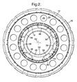
Figure 2 is a cross sectional view of the gas turbine engine combustion section shown inFigure 1 along the line II-II; -
Figure 3 is a cross section view of the damping tube of the resonator along the lines III-III in the drawing ofFigure 1 ; -
Figure 4 is a cross section view of the damping tube shown inFigure 3 along the line IV-IV in the drawing ofFigure 3 ; and -
Figure 5 is a perspective view of the damping tube showing the beam paths of a laser in a process of laser drilling cooling holes in the tube wall. - Referring to
Figure 1 , thecombustion section 10 of a gas turbine aero engine is illustrated with the adjacent engine parts omitted for clarity, that is the compressor section upstream of the combustor (to the left of the drawing inFigure 1 ) and the turbine section downstream of the combustion section. The combustion section comprises an annulartype combustion chamber 12 positioned in anannular region 14 between a combustion chamberouter casing 16, which is part of the engine casing structure and radially outwards of the combustion chamber, and a combustion chamberinner casing 18, also part of the engine structure and positioned radially inwards of thecombustion chamber 12. Theinner casing 16 andouter casing 18 comprise part of the engine casing load bearing structure and the function of these components is well understood by those skilled in the art. Thecombustion chamber 12 is cantilevered at its downstream end from an annular array ofnozzle guide vanes 20, one of which is shown in part in the drawing ofFigure 1 . In this arrangement the combustion chamber may be considered to be a non load bearing component in the sense that it does not support any loads other than the loads acting upon it due to the pressure differential across the walls of the combustion chamber. - The combustion chamber comprises a continuous heat shield type lining on its radially inner and outer interior surfaces. The lining comprises a series of heat
resistant tiles 22 which are attached to the interior surface of the radially inner and outer walls of the combustor in a known manner. The upstream end of the combustion chamber comprises anannular end wall 24, which includes a series of circumferentially spacedapertures 26 for receiving respective airfuel injection devices 28. The radially outer wall of the combustion chamber includes at least one opening 30 for receiving the end of anignitor 32, which passes through a corresponding aperture in theouter casing 16 on which it is secured. - The radially inner wall of the combustion chamber is provided with a plurality of circumferentially spaced
apertures 34 for receiving the end part of a Helmholtzresonator damping tube 36. Each Helmholtzresonator 38 comprises a box likeresonator cavity 40 which is in flow communication with the interior of the combustion chamber through thedamping tube 36 which extends radially from theresonator cavity 40 into theinterior 41 of the combustor. In the drawing ofFigure 1 theresonator cavity 40 extends circumferentially around part of the circumference of the combustion chamberinner casing 18 on the radially inner side thereof. Thedamping tube 36 extends through a respective aperture in theinner casing 18 in register with theaperture 34 in the combustion chamber inner wall. In this embodiment the damping tube has a substantially circular cross section although tubes having cross sections other than circular may be used. The Helmholtzresonator 38 is fixed to theinner casing 18 by fixing means 42 in the form of bolts, studs or the like. Theresonator 38 is therefore mounted and supported independently of thecombustion chamber 12. An annular sealing member 44 is provided around the outer periphery of the tube to provide a gas tight seal between the tube and the opening 34. The tube provides for limited relative axial movement of the tube with respect to the combustion chamber so that substantially no load is transferred from the resonator tube to the combustion chamber during engine operation. - As can best be seen in the cross section drawing of
Figure 2 , sevenresonators 38 are positioned around the radially inner side of the combustion chamberinner casing 18. The resonators are arranged in two groups one including four resonators and the other group including the other three. The resonators have different circumferential dimensions such that the volume of therespective cavities 40 of the resonators is different for each resonator. This difference in cavity volume has the effect of ensuring each resonator has a different resonator frequency such that therespective resonators 38 compliment one another in the sense that collectively the resonators operate over a wide frequency band to damp pressure oscillations in the combustion chamber over substantially the entire running range of the engine. Each resonator has a particularly frequency and theresonator cavities 40 are sized such that the different resonator frequencies do not substantially overlap. - The resonator cavities are enclosed in an
annular cavity 46 defined on one side by the combustion chamberinner casing 18 and along the other side by awindage shield 48, which, in use, functions to reduce windage losses between thebox type resonators 38 and the highpressure engine shaft 50 when it rotates about theengine axis 52. Thewindage shield 48 extends annularly around theinner casing 18 to enclose all sevenresonators 38 in a streamlined manner so that windage losses are not generated by the close proximity of the resonator cavities to theengine shaft 50. A further function of thewindage shield 48 is that it provides a containment structure in the event of mechanical failure of any one of theresonators 38. In the event of a mechanical failure resulting in the loss of structural integrity of a resonator, or other engine components, the windage shield acts to prevent the occurrence of secondary damage to the engine by contact with theengine shaft 50.Apertures 53 are provided in the combustion chamberinner casing 18 to allow flow communication between theannular region 14, and theannular cavity 46 defined by thewindage shield 48 and the combustion chamberinner casing 18. This ensures that, during engine operation, the enclosedvolume 46 of the windage shield is at the same pressure as theannular region 14 surrounding the combustion chamber, which is at higher pressure than thecombustion chamber interior 41. The resultant pressure difference guarantees that, in the event of mechanical failure of any one of the resonators, air flows air into thecombustion chamber 12 from the enclosedvolume 46, preventing the escape of hot exhaust gasses that would severely hazard, for example, theengine shaft 50. - Referring now to
Figures 3-5 which show various views of thedamping tube 36 common to each of theresonators 38. As can be seen inFigure 3 , the tube has a circular cross section with a plurality of circumferentially spacedcooling holes 54 formed in the tube wall. Thecooling holes 54 are equally spaced around the tube circumference and are inclined with respect to respective lines tangential to the tube circumference at the hole locations. As can be seen in the drawings ofFigures 4 and 5 two rows of cooling holes are provided in axially spaced relation along the length of the tube. In one embodiment the tube comprises twenty 0.5mm diameter holes in each row in a 16.0mm diameter tube. The rows of cooling holes are preferably positioned towards the open end of the tube in the combustion chamber. For instance, the first row of holes may be positioned a quarter to a third of the way along the length of the tube from the combustion chamber end, with the second row approximately halfway along the tube. - As shown in
Figure 3 , in the plane perpendicular to the longitudinal axis of the tube the cooling holes 54 are angled so that they have both a radial and tangential component with respect to the circumference of the tube. Each hole is inclined at angle 45 degrees, as indicated byangle 56 in the drawing ofFigure 3 , with respect to theradial line 58 through the respective hole and the tube longitudinal axis. This promotes vortex flow on the interior surface of the tube when cooling air passes from the exterior region of the tube into the interior region thereof. - Referring now to
Figure 4 , it can also be seen that the holes are angled with respect to thelongitudinal axis 60 of the tube. In the illustrated embodiment the holes have an angle of 30 degrees, indicated byangle 62 in the drawing, and are inclined towards the combustion chamber end of the tube such that the respective axis of the holes converge towards thetube axis 60. The three dimensional nature of the inclination of the holes with respect to the wall of the tube is more clearly presented inFigure 5 which shows the path ofrespective laser beams 64 passing through the holes and the open end of the tube during laser drilling of the holes. As the beams follow a substantially straight line the beams are indicative of the cooling hole axes. - Although aspects of the invention have been described with reference to the embodiments shown in the accompanying drawing, it is to be understood that the invention is not limited to those precise embodiments and that various changes and modifications may be effected without further inventive skill and effort. For example, other cooling hole configurations may be used including arrangements where the holes are arranged in several rows, in line, or staggered with respect to each other, with different diameters, number of holes and angles depending on the specific cooling requirements of the particular combustion chamber application. In addition, different shaped holes may be employed instead of substantially circular cross section holes. The drawings of
Figures 1 and2 show the resonators positioned on the radially inner side of the combustion chamber and mounted to the combustion chamber inner casing. In other embodiments the resonators may be located on the radially outer side of the combustion chamber and secured to the combustion chamberouter casing 16. In the latter arrangement a windage shield would not necessarily be required.
Claims (5)
- A combustion chamber for a gas turbine engine comprising an annular region (14) defined by a combustion chamber inner casing (18) and a combustion chamber outer casing (16); a combustion chamber (12) located in the annular region (14) and comprising at least one Helmholtz resonator (38) having a cavity (40) and a damping tube (36) in flow communication with the interior (41) of the combustion chamber (12),
characterised in that the damping tube (36) extends into the interior (41) of the combustion chamber (12), and the at least one Helmholtz resonator (38) is supported independently of the combustion chamber (12) by the said combustion chamber inner casing (18), and the at least one Helmholtz resonator (38) is supported by the combustion chamber inner casing (18) with the at least one Helmholtz resonator (38) positioned on the radially inner side of the combustion chamber (12) and enclosed within a cavity (46) provided between the combustion chamber inner casing (18) and a windage shield (48) on a radially inner side of the said casing (18). - A combustion section as claimed in Claim 1 further characterised in that the at least one Helmholtz resonator comprises a plurality of Helmholtz resonators (38), each enclosed within the cavity (46) provided by the said windage shield (48).
- A combustion section as claimed in Claim 2 further characterised in that the said plurality of Helmholtz resonators (38) are circumferentially spaced around the combustion chamber(12).
- A combustion section as claimed in Claim 2 or Claim 3 further characterised in that the plurality of Helmholtz resonators (38) each has a cavity (40) and a damping tube (36) in flow communication with the interior (41) of the combustion chamber (12), wherein the damping tube (36) extends into the interior (41) of the combustion chamber (12), and the Helmholtz resonators (38) are spaced around an inner circumference of the combustion chamber (12) with the respective cavities (40) of diametrically opposed resonators (38) having substantially different volumes.
- A combustion chamber as claimed in any one of Claims 2 to 4 wherein the plurality of Helmholtz resonators (38) are circumferentially spaced around the combustion chamber (12) with the cavities (40) of respective resonators having successively smaller volumes.
Applications Claiming Priority (2)
| Application Number | Priority Date | Filing Date | Title |
|---|---|---|---|
| GB0229755A GB2396687A (en) | 2002-12-23 | 2002-12-23 | Helmholtz resonator for combustion chamber use |
| EP03258004A EP1434006A3 (en) | 2002-12-23 | 2003-12-18 | Combustion chamber for gas turbine engine |
Related Parent Applications (1)
| Application Number | Title | Priority Date | Filing Date |
|---|---|---|---|
| EP03258004A Division EP1434006A3 (en) | 2002-12-23 | 2003-12-18 | Combustion chamber for gas turbine engine |
Publications (2)
| Publication Number | Publication Date |
|---|---|
| EP1962018A1 true EP1962018A1 (en) | 2008-08-27 |
| EP1962018B1 EP1962018B1 (en) | 2015-10-14 |
Family
ID=9950118
Family Applications (2)
| Application Number | Title | Priority Date | Filing Date |
|---|---|---|---|
| EP08009068.1A Expired - Lifetime EP1962018B1 (en) | 2002-12-23 | 2003-12-18 | Combustion chamber for gas turbine engine |
| EP03258004A Withdrawn EP1434006A3 (en) | 2002-12-23 | 2003-12-18 | Combustion chamber for gas turbine engine |
Family Applications After (1)
| Application Number | Title | Priority Date | Filing Date |
|---|---|---|---|
| EP03258004A Withdrawn EP1434006A3 (en) | 2002-12-23 | 2003-12-18 | Combustion chamber for gas turbine engine |
Country Status (3)
| Country | Link |
|---|---|
| US (1) | US7076956B2 (en) |
| EP (2) | EP1962018B1 (en) |
| GB (1) | GB2396687A (en) |
Cited By (3)
| Publication number | Priority date | Publication date | Assignee | Title |
|---|---|---|---|---|
| CN102116475A (en) * | 2010-01-06 | 2011-07-06 | 通用电气公司 | Method and apparatus of combustor dynamics mitigation |
| DE102011016917A1 (en) | 2011-04-13 | 2012-10-18 | Rolls-Royce Deutschland Ltd & Co Kg | Gas turbine combustor with a holder of a seal for an attachment |
| DE102014214775A1 (en) * | 2014-07-28 | 2016-01-28 | Rolls-Royce Deutschland Ltd & Co Kg | Aircraft gas turbine with a seal for sealing a spark plug on the combustion chamber wall of a gas turbine |
Families Citing this family (42)
| Publication number | Priority date | Publication date | Assignee | Title |
|---|---|---|---|---|
| GB0305025D0 (en) | 2003-03-05 | 2003-04-09 | Alstom Switzerland Ltd | Method and device for efficient usage of cooling air for acoustic damping of combustion chamber pulsations |
| ITTO20031013A1 (en) * | 2003-12-16 | 2005-06-17 | Ansaldo Energia Spa | THERMO ACOUSTIC INSTABILITY DAMPING SYSTEM IN A COMBUSTOR DEVICE FOR A GAS TURBINE. |
| DE502004011481D1 (en) * | 2004-06-07 | 2010-09-16 | Siemens Ag | Combustion chamber with a damping device for damping thermoacoustic oscillations |
| US7334408B2 (en) * | 2004-09-21 | 2008-02-26 | Siemens Aktiengesellschaft | Combustion chamber for a gas turbine with at least two resonator devices |
| GB0427147D0 (en) | 2004-12-11 | 2005-01-12 | Rolls Royce Plc | Combustion chamber for a gas turbine engine |
| DE102005062284B4 (en) * | 2005-12-24 | 2019-02-28 | Ansaldo Energia Ip Uk Limited | Combustion chamber for a gas turbine |
| US7413053B2 (en) * | 2006-01-25 | 2008-08-19 | Siemens Power Generation, Inc. | Acoustic resonator with impingement cooling tubes |
| DE102006011248A1 (en) * | 2006-03-10 | 2007-09-13 | Rolls-Royce Deutschland Ltd & Co Kg | Gas turbine combustion chamber wall has damping recesses for inner wall, with respective center axis arranged perpendicularly to inner wall, and cooling recesses, with respective center axis inclined at angle to inner wall |
| DE102006011247A1 (en) * | 2006-03-10 | 2007-09-13 | Rolls-Royce Deutschland Ltd & Co Kg | Gas turbine combustion chamber wall has damping recesses for inner wall, with respective center axis arranged perpendicularly to inner wall, and cooling recesses, with respective center axis inclined at angle to inner wall |
| EP1832812A3 (en) * | 2006-03-10 | 2012-01-04 | Rolls-Royce Deutschland Ltd & Co KG | Gas turbine combustion chamber wall with absorption of combustion chamber vibrations |
| GB0610800D0 (en) | 2006-06-01 | 2006-07-12 | Rolls Royce Plc | Combustion chamber for a gas turbine engine |
| US7788926B2 (en) * | 2006-08-18 | 2010-09-07 | Siemens Energy, Inc. | Resonator device at junction of combustor and combustion chamber |
| US8313286B2 (en) * | 2008-07-28 | 2012-11-20 | Siemens Energy, Inc. | Diffuser apparatus in a turbomachine |
| EP2187125A1 (en) * | 2008-09-24 | 2010-05-19 | Siemens Aktiengesellschaft | Method and device for damping combustion oscillation |
| US8408004B2 (en) * | 2009-06-16 | 2013-04-02 | General Electric Company | Resonator assembly for mitigating dynamics in gas turbines |
| US9650903B2 (en) * | 2009-08-28 | 2017-05-16 | United Technologies Corporation | Combustor turbine interface for a gas turbine engine |
| ES2400267T3 (en) * | 2009-08-31 | 2013-04-08 | Alstom Technology Ltd | Combustion device of a gas turbine |
| RU2508506C2 (en) * | 2009-09-01 | 2014-02-27 | Дженерал Электрик Компани | Method and unit for fluid feed in gas turbine engine combustion chamber |
| EP2299177A1 (en) * | 2009-09-21 | 2011-03-23 | Alstom Technology Ltd | Combustor of a gas turbine |
| EP2362147B1 (en) | 2010-02-22 | 2012-12-26 | Alstom Technology Ltd | Combustion device for a gas turbine |
| US8973365B2 (en) | 2010-10-29 | 2015-03-10 | Solar Turbines Incorporated | Gas turbine combustor with mounting for Helmholtz resonators |
| US8469141B2 (en) | 2011-08-10 | 2013-06-25 | General Electric Company | Acoustic damping device for use in gas turbine engine |
| US20130081397A1 (en) * | 2011-10-04 | 2013-04-04 | Brandon Taylor Overby | Forward casing with a circumferential sloped surface and a combustor assembly including same |
| US20130255260A1 (en) * | 2012-03-29 | 2013-10-03 | Solar Turbines Inc. | Resonance damper for damping acoustic oscillations from combustor |
| US20130283799A1 (en) * | 2012-04-25 | 2013-10-31 | Solar Turbines Inc. | Resonance damper for damping acoustic oscillations from combustor |
| DE102012015452A1 (en) * | 2012-08-03 | 2014-04-24 | Rolls-Royce Deutschland Ltd & Co Kg | Gas turbine combustion chamber wall for gas turbine engine, has mixed air openings formed by tubular air guide elements, which are fastened at wall and penetrate shingles arranged at inner side of wall |
| US9400108B2 (en) | 2013-05-14 | 2016-07-26 | Siemens Aktiengesellschaft | Acoustic damping system for a combustor of a gas turbine engine |
| EP2881667B1 (en) * | 2013-10-11 | 2017-04-26 | General Electric Technology GmbH | Helmholtz damper with air cooled seal for a gas turbine |
| EP2865947B1 (en) * | 2013-10-28 | 2017-08-23 | Ansaldo Energia Switzerland AG | Damper for gas turbine |
| EP3026346A1 (en) * | 2014-11-25 | 2016-06-01 | Alstom Technology Ltd | Combustor liner |
| EP3227611A1 (en) * | 2014-12-01 | 2017-10-11 | Siemens Aktiengesellschaft | Resonators with interchangeable metering tubes for gas turbine engines |
| CN104566477B (en) * | 2014-12-31 | 2019-02-01 | 北京华清燃气轮机与煤气化联合循环工程技术有限公司 | Frequency modulation device and term durability gas turbine flame barrel for term durability gas turbine flame barrel |
| US10513984B2 (en) | 2015-08-25 | 2019-12-24 | General Electric Company | System for suppressing acoustic noise within a gas turbine combustor |
| US10197275B2 (en) * | 2016-05-03 | 2019-02-05 | General Electric Company | High frequency acoustic damper for combustor liners |
| US10670271B2 (en) * | 2016-09-30 | 2020-06-02 | DOOSAN Heavy Industries Construction Co., LTD | Acoustic dampening liner cap and gas turbine combustor including the same |
| DE102018216807A1 (en) * | 2018-09-28 | 2020-04-02 | Rolls-Royce Deutschland Ltd & Co Kg | Combustion chamber assembly for an engine with heat shields and / or burner seals of at least two different types |
| DE102020200204A1 (en) * | 2020-01-09 | 2021-07-15 | Siemens Aktiengesellschaft | Ceramic resonator for combustion chamber systems and combustion chamber systems |
| US11804206B2 (en) | 2021-05-12 | 2023-10-31 | Goodrich Corporation | Acoustic panel for noise attenuation |
| US11830467B2 (en) | 2021-10-16 | 2023-11-28 | Rtx Coroporation | Unit cell resonator networks for turbomachinery bypass flow structures |
| US11781485B2 (en) | 2021-11-24 | 2023-10-10 | Rtx Corporation | Unit cell resonator networks for gas turbine combustor tone damping |
| US11702992B2 (en) | 2021-12-03 | 2023-07-18 | Raytheon Company | Combustor wall core with resonator and/or damper elements |
| US11970969B2 (en) | 2022-06-29 | 2024-04-30 | General Electric Company | Compressor bypass bleed system for a ducted fan engine |
Citations (7)
| Publication number | Priority date | Publication date | Assignee | Title |
|---|---|---|---|---|
| US4199936A (en) * | 1975-12-24 | 1980-04-29 | The Boeing Company | Gas turbine engine combustion noise suppressor |
| US5644918A (en) | 1994-11-14 | 1997-07-08 | General Electric Company | Dynamics free low emissions gas turbine combustor |
| US5685157A (en) * | 1995-05-26 | 1997-11-11 | General Electric Company | Acoustic damper for a gas turbine engine combustor |
| DE19640980A1 (en) * | 1996-10-04 | 1998-04-16 | Asea Brown Boveri | Device for damping thermo-acoustic vibrations in combustion chamber of gas turbine |
| EP1158247A2 (en) * | 2000-05-26 | 2001-11-28 | ALSTOM Power N.V. | Apparatus to reduce acoustic vibrations in a combustion chamber |
| WO2002025174A1 (en) * | 2000-09-21 | 2002-03-28 | Siemens Westinghouse Power Corporation | Modular resonators for suppressing combustion instabilities in gas turbine power plants |
| US6464489B1 (en) * | 1997-11-24 | 2002-10-15 | Alstom | Method and apparatus for controlling thermoacoustic vibrations in a combustion system |
Family Cites Families (16)
| Publication number | Priority date | Publication date | Assignee | Title |
|---|---|---|---|---|
| US2807931A (en) * | 1951-06-16 | 1957-10-01 | Jr Albert G Bodine | Control of combustion instability in jet engines |
| US3982392A (en) * | 1974-09-03 | 1976-09-28 | General Motors Corporation | Combustion apparatus |
| GB1602836A (en) * | 1977-05-11 | 1981-11-18 | Lucas Industries Ltd | Sealing arrangement for use in a combustion assembly |
| DE3324805A1 (en) * | 1983-07-09 | 1985-01-17 | Betriebsforschungsinstitut VDEh - Institut für angewandte Forschung GmbH, 4000 Düsseldorf | Device for the prevention of pressure fluctuations in combustion chambers |
| US4786188A (en) * | 1986-02-27 | 1988-11-22 | Rosemont Inc. | Purge air system for a combustion instrument |
| GB8703101D0 (en) * | 1987-02-11 | 1987-03-18 | Secr Defence | Gas turbine engine combustion chambers |
| US4820097A (en) * | 1988-03-18 | 1989-04-11 | United Technologies Corporation | Fastener with airflow opening |
| GB9003959D0 (en) * | 1990-02-21 | 1990-04-18 | Ross Colin F | Active control of internal combustion engine performance |
| FR2683891B1 (en) * | 1991-11-20 | 1995-03-24 | Snecma | TURBOMACHINE COMPRISING A DEVICE FOR REDUCING THE EMISSION OF NITROGEN OXIDES. |
| EP0597138B1 (en) * | 1992-11-09 | 1997-07-16 | Asea Brown Boveri AG | Combustion chamber for gas turbine |
| DE4414232A1 (en) * | 1994-04-23 | 1995-10-26 | Abb Management Ag | Device for damping thermoacoustic vibrations in a combustion chamber |
| EP0974788B1 (en) * | 1998-07-23 | 2014-11-26 | Alstom Technology Ltd | Device for directed noise attenuation in a turbomachine |
| DE19851636A1 (en) * | 1998-11-10 | 2000-05-11 | Asea Brown Boveri | Damping device for reducing vibration amplitude of acoustic waves for burner for internal combustion engine operation is preferably for driving gas turbo-group, with mixture area for air and fuel |
| US6354733B2 (en) * | 1999-01-15 | 2002-03-12 | Ametex, Inc. | System and method for determining combustion temperature using infrared emissions |
| US6351947B1 (en) * | 2000-04-04 | 2002-03-05 | Abb Alstom Power (Schweiz) | Combustion chamber for a gas turbine |
| GB2373319B (en) * | 2001-03-12 | 2005-03-30 | Rolls Royce Plc | Combustion apparatus |
-
2002
- 2002-12-23 GB GB0229755A patent/GB2396687A/en not_active Withdrawn
-
2003
- 2003-12-15 US US10/734,129 patent/US7076956B2/en not_active Expired - Lifetime
- 2003-12-18 EP EP08009068.1A patent/EP1962018B1/en not_active Expired - Lifetime
- 2003-12-18 EP EP03258004A patent/EP1434006A3/en not_active Withdrawn
Patent Citations (7)
| Publication number | Priority date | Publication date | Assignee | Title |
|---|---|---|---|---|
| US4199936A (en) * | 1975-12-24 | 1980-04-29 | The Boeing Company | Gas turbine engine combustion noise suppressor |
| US5644918A (en) | 1994-11-14 | 1997-07-08 | General Electric Company | Dynamics free low emissions gas turbine combustor |
| US5685157A (en) * | 1995-05-26 | 1997-11-11 | General Electric Company | Acoustic damper for a gas turbine engine combustor |
| DE19640980A1 (en) * | 1996-10-04 | 1998-04-16 | Asea Brown Boveri | Device for damping thermo-acoustic vibrations in combustion chamber of gas turbine |
| US6464489B1 (en) * | 1997-11-24 | 2002-10-15 | Alstom | Method and apparatus for controlling thermoacoustic vibrations in a combustion system |
| EP1158247A2 (en) * | 2000-05-26 | 2001-11-28 | ALSTOM Power N.V. | Apparatus to reduce acoustic vibrations in a combustion chamber |
| WO2002025174A1 (en) * | 2000-09-21 | 2002-03-28 | Siemens Westinghouse Power Corporation | Modular resonators for suppressing combustion instabilities in gas turbine power plants |
Cited By (6)
| Publication number | Priority date | Publication date | Assignee | Title |
|---|---|---|---|---|
| CN102116475A (en) * | 2010-01-06 | 2011-07-06 | 通用电气公司 | Method and apparatus of combustor dynamics mitigation |
| CN102116475B (en) * | 2010-01-06 | 2015-06-03 | 通用电气公司 | Method and apparatus of combustor dynamics mitigation |
| DE102011016917A1 (en) | 2011-04-13 | 2012-10-18 | Rolls-Royce Deutschland Ltd & Co Kg | Gas turbine combustor with a holder of a seal for an attachment |
| US8677765B2 (en) | 2011-04-13 | 2014-03-25 | Rolls-Royce Deutschland Ltd & Co Kg | Gas-turbine combustion chamber with a holding mechanism for a seal for an attachment |
| DE102014214775A1 (en) * | 2014-07-28 | 2016-01-28 | Rolls-Royce Deutschland Ltd & Co Kg | Aircraft gas turbine with a seal for sealing a spark plug on the combustion chamber wall of a gas turbine |
| US9982783B2 (en) | 2014-07-28 | 2018-05-29 | Rolls-Royce Deutschland Ltd & Co Kg | Aircraft gas turbine with a seal for sealing an igniter plug on the combustion chamber wall of a gas turbine |
Also Published As
| Publication number | Publication date |
|---|---|
| US20040211185A1 (en) | 2004-10-28 |
| US7076956B2 (en) | 2006-07-18 |
| EP1434006A2 (en) | 2004-06-30 |
| EP1434006A3 (en) | 2006-03-01 |
| GB0229755D0 (en) | 2003-01-29 |
| EP1962018B1 (en) | 2015-10-14 |
| GB2396687A (en) | 2004-06-30 |
Similar Documents
| Publication | Publication Date | Title |
|---|---|---|
| EP1962018B1 (en) | Combustion chamber for gas turbine engine | |
| EP1669670B1 (en) | Helmholtz resonator for a combustion chamber for a gas turbine engine | |
| EP1862739B1 (en) | Combustion chamber for a gas turbine engine | |
| CN108626747B (en) | Combustor acoustic damping structure | |
| US7874138B2 (en) | Segmented annular combustor | |
| US5685157A (en) | Acoustic damper for a gas turbine engine combustor | |
| EP3290805B1 (en) | Fuel nozzle assembly with resonator | |
| JP2019526028A (en) | Gas turbine engine with resonator ring | |
| US9249734B2 (en) | Combustor | |
| KR20100061538A (en) | Secondary fuel delivery system | |
| US5572863A (en) | Resilient annular mounting member for a transition duct of a combustion chamber | |
| US11041625B2 (en) | Fuel nozzle with narrow-band acoustic damper | |
| US10415480B2 (en) | Gas turbine engine fuel manifold damper and method of dynamics attenuation | |
| EP1677050A2 (en) | Augmentor liner | |
| EP3452756B1 (en) | High frequency acoustic damper for combustor liners and method of damping | |
| EP3309457B1 (en) | Combustion dynamics mitigation system | |
| JPH09196377A (en) | Gas turbine combustor | |
| WO2021020372A1 (en) | Acoustic attenuator, tube assembly, combustor, gas turbine, and method for manufacturing tube assembly | |
| KR102146564B1 (en) | Combustor and gas turbine with reduction structure of combustion resonance | |
| US11788724B1 (en) | Acoustic damper for combustor | |
| CN116324130A (en) | Seal assembly for turbine spray cone |
Legal Events
| Date | Code | Title | Description |
|---|---|---|---|
| PUAI | Public reference made under article 153(3) epc to a published international application that has entered the european phase |
Free format text: ORIGINAL CODE: 0009012 |
|
| AC | Divisional application: reference to earlier application |
Ref document number: 1434006 Country of ref document: EP Kind code of ref document: P |
|
| AK | Designated contracting states |
Kind code of ref document: A1 Designated state(s): DE FR GB |
|
| 17P | Request for examination filed |
Effective date: 20090119 |
|
| AKX | Designation fees paid |
Designated state(s): DE FR GB |
|
| GRAP | Despatch of communication of intention to grant a patent |
Free format text: ORIGINAL CODE: EPIDOSNIGR1 |
|
| INTG | Intention to grant announced |
Effective date: 20150616 |
|
| RAP1 | Party data changed (applicant data changed or rights of an application transferred) |
Owner name: ROLLS-ROYCE PLC Owner name: ROLLS-ROYCE DEUTSCHLAND LTD & CO KG |
|
| GRAS | Grant fee paid |
Free format text: ORIGINAL CODE: EPIDOSNIGR3 |
|
| GRAA | (expected) grant |
Free format text: ORIGINAL CODE: 0009210 |
|
| AC | Divisional application: reference to earlier application |
Ref document number: 1434006 Country of ref document: EP Kind code of ref document: P |
|
| AK | Designated contracting states |
Kind code of ref document: B1 Designated state(s): DE FR GB |
|
| REG | Reference to a national code |
Ref country code: GB Ref legal event code: FG4D |
|
| REG | Reference to a national code |
Ref country code: DE Ref legal event code: R096 Ref document number: 60348149 Country of ref document: DE |
|
| REG | Reference to a national code |
Ref country code: FR Ref legal event code: PLFP Year of fee payment: 13 |
|
| REG | Reference to a national code |
Ref country code: DE Ref legal event code: R082 Ref document number: 60348149 Country of ref document: DE Representative=s name: HERNANDEZ, YORCK, DIPL.-ING., DE |
|
| REG | Reference to a national code |
Ref country code: DE Ref legal event code: R097 Ref document number: 60348149 Country of ref document: DE |
|
| PLBE | No opposition filed within time limit |
Free format text: ORIGINAL CODE: 0009261 |
|
| STAA | Information on the status of an ep patent application or granted ep patent |
Free format text: STATUS: NO OPPOSITION FILED WITHIN TIME LIMIT |
|
| 26N | No opposition filed |
Effective date: 20160715 |
|
| REG | Reference to a national code |
Ref country code: FR Ref legal event code: PLFP Year of fee payment: 14 |
|
| REG | Reference to a national code |
Ref country code: FR Ref legal event code: PLFP Year of fee payment: 15 |
|
| PGFP | Annual fee paid to national office [announced via postgrant information from national office to epo] |
Ref country code: GB Payment date: 20221220 Year of fee payment: 20 Ref country code: FR Payment date: 20221222 Year of fee payment: 20 |
|
| PGFP | Annual fee paid to national office [announced via postgrant information from national office to epo] |
Ref country code: DE Payment date: 20221227 Year of fee payment: 20 |
|
| P01 | Opt-out of the competence of the unified patent court (upc) registered |
Effective date: 20230528 |
|
| REG | Reference to a national code |
Ref country code: DE Ref legal event code: R071 Ref document number: 60348149 Country of ref document: DE |
|
| REG | Reference to a national code |
Ref country code: GB Ref legal event code: PE20 Expiry date: 20231217 |
|
| PG25 | Lapsed in a contracting state [announced via postgrant information from national office to epo] |
Ref country code: GB Free format text: LAPSE BECAUSE OF EXPIRATION OF PROTECTION Effective date: 20231217 |
|
| PG25 | Lapsed in a contracting state [announced via postgrant information from national office to epo] |
Ref country code: GB Free format text: LAPSE BECAUSE OF EXPIRATION OF PROTECTION Effective date: 20231217 |