US20170187249A1 - Wireless Charging With Multiple Power Receiving Facilities On A Wireless Device - Google Patents
Wireless Charging With Multiple Power Receiving Facilities On A Wireless Device Download PDFInfo
- Publication number
- US20170187249A1 US20170187249A1 US15/461,121 US201715461121A US2017187249A1 US 20170187249 A1 US20170187249 A1 US 20170187249A1 US 201715461121 A US201715461121 A US 201715461121A US 2017187249 A1 US2017187249 A1 US 2017187249A1
- Authority
- US
- United States
- Prior art keywords
- power
- wireless power
- antennas
- wireless
- antenna
- Prior art date
- Legal status (The legal status is an assumption and is not a legal conclusion. Google has not performed a legal analysis and makes no representation as to the accuracy of the status listed.)
- Abandoned
Links
- 238000004891 communication Methods 0.000 claims description 37
- 230000005540 biological transmission Effects 0.000 claims description 14
- 238000001514 detection method Methods 0.000 claims description 6
- 238000012545 processing Methods 0.000 claims description 6
- 238000001914 filtration Methods 0.000 claims description 4
- 230000033228 biological regulation Effects 0.000 claims description 2
- 230000001105 regulatory effect Effects 0.000 claims description 2
- 230000001276 controlling effect Effects 0.000 claims 1
- 238000000034 method Methods 0.000 description 37
- 230000015654 memory Effects 0.000 description 29
- 238000010586 diagram Methods 0.000 description 22
- 238000005516 engineering process Methods 0.000 description 13
- 230000008569 process Effects 0.000 description 13
- 238000007726 management method Methods 0.000 description 9
- 230000005855 radiation Effects 0.000 description 6
- 230000008901 benefit Effects 0.000 description 5
- 238000013461 design Methods 0.000 description 5
- 230000001427 coherent effect Effects 0.000 description 4
- 230000008878 coupling Effects 0.000 description 4
- 238000010168 coupling process Methods 0.000 description 4
- 238000005859 coupling reaction Methods 0.000 description 4
- 230000007246 mechanism Effects 0.000 description 4
- 230000003287 optical effect Effects 0.000 description 3
- 230000011664 signaling Effects 0.000 description 3
- 238000012546 transfer Methods 0.000 description 3
- 230000009471 action Effects 0.000 description 2
- 239000003990 capacitor Substances 0.000 description 2
- 230000001413 cellular effect Effects 0.000 description 2
- 238000006243 chemical reaction Methods 0.000 description 2
- UGFAIRIUMAVXCW-UHFFFAOYSA-N Carbon monoxide Chemical compound [O+]#[C-] UGFAIRIUMAVXCW-UHFFFAOYSA-N 0.000 description 1
- 238000004458 analytical method Methods 0.000 description 1
- 230000000903 blocking effect Effects 0.000 description 1
- 229910002091 carbon monoxide Inorganic materials 0.000 description 1
- 230000003111 delayed effect Effects 0.000 description 1
- 230000000694 effects Effects 0.000 description 1
- 230000005284 excitation Effects 0.000 description 1
- 230000006870 function Effects 0.000 description 1
- 230000007274 generation of a signal involved in cell-cell signaling Effects 0.000 description 1
- 238000003384 imaging method Methods 0.000 description 1
- 230000008676 import Effects 0.000 description 1
- 239000004973 liquid crystal related substance Substances 0.000 description 1
- 238000012423 maintenance Methods 0.000 description 1
- 238000005259 measurement Methods 0.000 description 1
- 238000012986 modification Methods 0.000 description 1
- 230000004048 modification Effects 0.000 description 1
- 238000005457 optimization Methods 0.000 description 1
- 238000013021 overheating Methods 0.000 description 1
- 230000000737 periodic effect Effects 0.000 description 1
- 230000002093 peripheral effect Effects 0.000 description 1
- 230000010287 polarization Effects 0.000 description 1
- 238000001228 spectrum Methods 0.000 description 1
- 230000003068 static effect Effects 0.000 description 1
- 239000000126 substance Substances 0.000 description 1
- 230000001502 supplementing effect Effects 0.000 description 1
- 238000002604 ultrasonography Methods 0.000 description 1
Images
Classifications
-
- H—ELECTRICITY
- H02—GENERATION; CONVERSION OR DISTRIBUTION OF ELECTRIC POWER
- H02J—CIRCUIT ARRANGEMENTS OR SYSTEMS FOR SUPPLYING OR DISTRIBUTING ELECTRIC POWER; SYSTEMS FOR STORING ELECTRIC ENERGY
- H02J50/00—Circuit arrangements or systems for wireless supply or distribution of electric power
- H02J50/20—Circuit arrangements or systems for wireless supply or distribution of electric power using microwaves or radio frequency waves
-
- H—ELECTRICITY
- H02—GENERATION; CONVERSION OR DISTRIBUTION OF ELECTRIC POWER
- H02J—CIRCUIT ARRANGEMENTS OR SYSTEMS FOR SUPPLYING OR DISTRIBUTING ELECTRIC POWER; SYSTEMS FOR STORING ELECTRIC ENERGY
- H02J50/00—Circuit arrangements or systems for wireless supply or distribution of electric power
- H02J50/40—Circuit arrangements or systems for wireless supply or distribution of electric power using two or more transmitting or receiving devices
- H02J50/402—Circuit arrangements or systems for wireless supply or distribution of electric power using two or more transmitting or receiving devices the two or more transmitting or the two or more receiving devices being integrated in the same unit, e.g. power mats with several coils or antennas with several sub-antennas
-
- H—ELECTRICITY
- H02—GENERATION; CONVERSION OR DISTRIBUTION OF ELECTRIC POWER
- H02J—CIRCUIT ARRANGEMENTS OR SYSTEMS FOR SUPPLYING OR DISTRIBUTING ELECTRIC POWER; SYSTEMS FOR STORING ELECTRIC ENERGY
- H02J50/00—Circuit arrangements or systems for wireless supply or distribution of electric power
- H02J50/80—Circuit arrangements or systems for wireless supply or distribution of electric power involving the exchange of data, concerning supply or distribution of electric power, between transmitting devices and receiving devices
-
- H—ELECTRICITY
- H02—GENERATION; CONVERSION OR DISTRIBUTION OF ELECTRIC POWER
- H02J—CIRCUIT ARRANGEMENTS OR SYSTEMS FOR SUPPLYING OR DISTRIBUTING ELECTRIC POWER; SYSTEMS FOR STORING ELECTRIC ENERGY
- H02J50/00—Circuit arrangements or systems for wireless supply or distribution of electric power
- H02J50/90—Circuit arrangements or systems for wireless supply or distribution of electric power involving detection or optimisation of position, e.g. alignment
-
- H02J7/025—
-
- H—ELECTRICITY
- H02—GENERATION; CONVERSION OR DISTRIBUTION OF ELECTRIC POWER
- H02J—CIRCUIT ARRANGEMENTS OR SYSTEMS FOR SUPPLYING OR DISTRIBUTING ELECTRIC POWER; SYSTEMS FOR STORING ELECTRIC ENERGY
- H02J7/00—Circuit arrangements for charging or depolarising batteries or for supplying loads from batteries
- H02J7/02—Circuit arrangements for charging or depolarising batteries or for supplying loads from batteries for charging batteries from ac mains by converters
- H02J7/04—Regulation of charging current or voltage
-
- H—ELECTRICITY
- H02—GENERATION; CONVERSION OR DISTRIBUTION OF ELECTRIC POWER
- H02J—CIRCUIT ARRANGEMENTS OR SYSTEMS FOR SUPPLYING OR DISTRIBUTING ELECTRIC POWER; SYSTEMS FOR STORING ELECTRIC ENERGY
- H02J7/00—Circuit arrangements for charging or depolarising batteries or for supplying loads from batteries
- H02J7/0029—Circuit arrangements for charging or depolarising batteries or for supplying loads from batteries with safety or protection devices or circuits
- H02J7/00309—Overheat or overtemperature protection
Definitions
- FIG. 8 is an example integrated circuit block diagram with multiple antennas for receiving power.
- the wireless technologies may include dedicated hardware components to deliver power and/or data.
- the dedicated hardware components may be modified based on the wireless technology, or combination of wireless technologies, being utilized. For example, when applied to sound waves, the system employs microphones and speakers rather than antennas.
- the antennas are adaptively-phased radio frequency antennas and the transmitter 101 utilizes a novel phase shifting algorithm as described in one or more of U.S. Pat. Nos. 8,558,661, 8,159,364, 8,410,953, 8,446,248, 8,854,176, U.S. patent application Ser. Nos. 14/461,332 and 14/815,893.
- the transmitter 101 is capable of determining the appropriate phases to deliver a coherent power transmission signal to the power receiver clients 103 .
- the array is configured to emit a signal (e.g., continuous wave or pulsed power transmission signal) from multiple antennas at a specific phase relative to each other.
- each wireless device 102 . 1 - 102 . n can be any system and/or device, and/or any combination of devices/systems that can establish a connection with another device, a server and/or other systems within the example environment 100 .
- the wireless devices 102 . 1 - 102 . n include displays or other output functionalities to present data to a user and/or input functionalities to receive data from the user.
- An optional motion sensor 395 detects motion and signals the control logic 310 .
- a device when a device is receiving power at high frequencies above 500 MHz, its location may become a hotspot of (incoming) radiation. So when the device is on a person, the level of radiation may exceed a regulation or exceed acceptable radiation levels set by medical/industrial authorities.
- the device may integrate motion detection mechanisms such as accelerometers, assisted GPS, or other mechanisms. Once the device detects that it is in motion, the disclosed system assumes that it is being handled by a user, and signals the power transmitting array either to stop transmitting power to it, or to lower the received power to an acceptable fraction of the power. In cases where the device is used in a moving environment like a car, train or plane, the power might only be transmitted intermittently or at a reduced level unless the device is close to losing all available power.
- a wireless device typically has a single wireless power receiver with a single antenna for receiving power.
- An example wireless power receiver is shown in FIG. 3 .
- antenna 390 receives wireless power and rectifier 350 rectifies the received RF power to direct current (DC), and then the DC power is integrated into the wireless device battery.
- DC direct current
- the wireless device can receive EM waves with varying properties.
- a transmitter can emit EM waves with various properties (e.g., direction, polarity, frequency, strength, phase), and these waves can be reflected or changed during in the transmission path (e.g., reflection from a wall or object).
- the wireless device has multiple wireless receivers with multiple antennas positioned in different locations it is more likely to receive power than a single wireless receiver with a single antenna.
- the details of a wireless power receiver 103 are described below in more detail with respect to FIGS. 7A-C and FIGS. 8-11 .
- the circuit can send communication from point “A” to point “C”. While not shown in FIG. 7B , point “C” is connected to an integrated circuit for communication such as communicate via BluetoothTM, WiFi, ZigBeeTM, or other wireless communication protocols. Before the signal is sent to the respective communication chip, a filter can remove the data from the wireless power signal. More details regarding the filter and circuit as described in FIG. 10 below.
- a central control unit e.g., a processor
- PA_Enable pulse and amplitude enabling signal
- a voltage reaches two op-amps 730 .
- the two-op amps 730 amplify the beaconing signal coming from “D”.
- a CPU or ASIC can generate the beacon signal that comes from “D”.
- antenna 705 transmits it.
- the bus also couples the processor to the non-volatile memory and drive unit.
- the non-volatile memory is often a magnetic floppy or hard disk, a magnetic-optical disk, an optical disk, a read-only memory (ROM), such as a CD-ROM, EPROM, or EEPROM, a magnetic or optical card, or another form of storage for large amounts of data. Some of this data is often written, by a direct memory access process, into memory during execution of software in the computer 13 .
- the non-volatile storage can be local, remote, or distributed.
- the non-volatile memory is optional because systems can be created with all applicable data available in memory.
- a typical computer system will usually include at least a processor, memory, and a device (e.g., a bus) coupling the memory to the processor.
- the machine operates as a standalone device or may be connected (e.g., networked) to other machines.
- the machine may operate in the capacity of a server or a client machine in a client-server network environment or as a peer machine in a peer-to-peer (or distributed) network environment).
Abstract
Description
- This application is a continuation of U.S. patent application Ser. No. 15/094,963, filed Apr. 8, 2016, titled “WIRELESS CHARGING WITH MULTIPLE POWER RECEIVING FACILITIES ON A WIRELESS DEVICE”; which claims priority to U.S. Provisional Application No. 62/256,694, filed Nov. 17, 2015, titled “INTEGRATED CHIPS INCORPORATING TRANSCEIVER COMPONENTS FOR REMOTE WIRELESS POWER DELIVERY AND FOR RECEIVING WIRELESS POWER,” and U.S. Provisional Application No. 62/163,964, filed May 19, 2015, titled “SYSTEMS AND METHODS FOR WIRELESS CHARGING,” and U.S. Provisional Application No. 62/146,233, filed Apr. 10, 2015, titled “SYSTEMS AND METHODS FOR WIRELESS CHARGING,” all of which are hereby incorporated by reference in their entireties.
- This application is related to U.S. patent application Ser. No. 15/094,952, filed Apr. 8, 2016, titled “CALCULATING POWER CONSUMPTION IN WIRELESS POWER DELIVERY SYSTEMS”; U.S. patent application Ser. No. 15/093,868, filed Apr. 8, 2016, titled “INFERRING BATTERY STATUS OF AN ELECTRONIC DEVICE IN A WIRELESS POWER DELIVERY ENVIRONMENT”; U.S. patent application Ser. No. 15/094,079, filed Apr. 8, 2016, titled “WIRELESS POWER TRANSCEIVERS FOR SUPPLEMENTING WIRELESS POWER DELIVERY AND EXTENDING RANGE”; U.S. patent application Ser. No. 15/093,023, filed Apr. 7, 2016, titled “TECHNIQUES FOR STATICALLY TUNING RETRO-DIRECTIVE WIRELESS POWER TRANSMISSION SYSTEMS”; U.S. patent application Ser. No. 15/092,026, filed Apr. 6, 2016, titled “ESTABLISHING CONNECTIONS WITH CHARGERS IN MULTI-CHARGER WIRELESS POWER DELIVERY ENVIRONMENTS”; U.S. patent application Ser. No. 15/091,986, filed Apr. 6, 2016, titled “TECHNIQUES FOR DELIVERING RETRODIRECTIVE WIRELESS POWER”; U.S. patent application Ser. No. 15/048,982, filed Feb. 19, 2016, titled “WIRELESSLY CHARGEABLE BATTERY APPARATUS”; U.S. patent application Ser. No. 15/048,984, filed Feb. 19, 2016, titled “REMOVABLY ATTACHABLE PORTABLE DEVICE APPARATUS WITH INTEGRATED WIRELESS POWER RECEIVING FACILITIES”; U.S. patent application Ser. No. 14/956,673, filed Dec. 2, 2015, titled “TECHNIQUES FOR ENCODING BEACON SIGNALS IN WIRELESS POWER DELIVERY ENVIRONMENTS”; U.S. patent application Ser. No. 14/945,741, filed Nov. 19, 2015, titled “TECHNIQUES FOR IMAGING WIRELESS POWER DELIVERY ENVIRONMENTS AND TRACKING OBJECTS THEREIN”; U.S. patent application Ser. No. 14/945,783, filed Nov. 19, 2015, titled “WIRELESSLY POWERED ELECTRONIC DISPLAY APPARATUSES”; U.S. patent application Ser. No. 14/926,014, filed Oct. 29, 2015, titled “TECHNIQUES FOR FILTERING MULTI-COMPONENT SIGNALS”; all of which are hereby incorporated by reference in their entireties.
- The technology described herein relates generally to the field of wireless communication and power transmission. More specifically, the technology relates to wireless power transfer to a device with multiple wireless power receivers.
- Many portable electronic devices are powered by batteries. Rechargeable batteries are often used to avoid the cost of replacing conventional dry-cell batteries and to conserve precious resources. However, recharging batteries with conventional rechargeable battery chargers requires access to an alternating current (AC) power outlet, which is sometimes not available or not convenient. It would, therefore, be desirable to derive power for a battery charger from EM radiation.
- Accordingly, a need exists for technology that overcomes the problem demonstrated above, as well as one that provides additional benefits. The examples provided herein are of some prior or related systems and their associated limitations are intended to be illustrative and not exclusive. Other limitations of existing or prior systems will become apparent to those of skill in the art upon reading the following detailed description.
- Overall, the examples herein of some prior or related systems and their associated limitations are intended to be illustrative and not exclusive. Other limitations of existing or prior systems will become apparent to those of skill in the art upon reading the following.
- One or more embodiments of the present invention are illustrated by way of example and not limitation in the figures of the accompanying drawings, in which like references indicate similar elements.
-
FIG. 1 is a diagram illustrating an example wireless power delivery environment depicting wireless power delivery from one or more wireless transmitters to various wireless devices within the wireless power delivery environment. -
FIG. 2 is a sequence diagram illustrating example operations between a wireless transmitter and a power receiver client for commencing wireless power delivery. -
FIG. 3 is a block diagram illustrating an example wireless power receiver (client) in accordance with an embodiment. -
FIG. 4 is a system overview diagram illustrating various components of the various embodiments described herein. -
FIGS. 5A-C are diagrams illustrating various examples of a wireless power system delivering power to a wireless device or devices having various numbers of receivers. -
FIG. 6 is an example diagram of a mobile electronic device with multiple wireless receivers. -
FIGS. 7A-C together are an example schematic diagram of a circuit for a receiver. -
FIG. 8 is an example integrated circuit block diagram with multiple antennas for receiving power. -
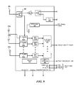
FIG. 9 is another example of an integrated circuit block diagram with multiple antennas for receiving wireless power. -
FIG. 10 is another example of an integrated circuit block diagram connected to central processing unit for data communication. -
FIG. 11 is an additional example of an integrated circuit block diagram illustrating multiple antennas for receiving power and communicating data. -
FIG. 12 is a diagrammatic representation of a machine in the example form of a computer system within which a set of instructions, for causing the machine to perform any one or more of the methodologies discussed herein, may be executed. -
FIG. 13 is a diagrammatic representation of a machine in the example form of a computer system within which a set of instructions, for causing the machine to perform any one or more of the methodologies discussed herein, may be executed. - The following description and drawings are illustrative and are not to be construed as limiting. Numerous specific details are described to provide a thorough understanding of the disclosure. However, in certain instances, well-known or conventional details are not described in order to avoid obscuring the description. References to “one” or “an” embodiment in the present disclosure can be, but not necessarily are, references to the same embodiment, and such references mean at least one of the embodiments.
- Reference in this specification to “one embodiment” or “an embodiment” means that a particular feature, structure, or characteristic described in connection with the embodiment is included in at least one embodiment of the disclosure. The appearances of the phrase “in one embodiment” in various places in the specification are not necessarily all referring to the same embodiment, nor are separate or alternative embodiments mutually exclusive of other embodiments. Moreover, various features are described which may be exhibited by some embodiments and not by others. Similarly, various requirements are described which may be requirements for some embodiments but no other embodiments.
- The terms used in this specification generally have their ordinary meanings in the art within the context of the disclosure and in the specific context where each term is used. Certain terms that are used to describe the disclosure are discussed below, or elsewhere in the specification, to provide additional guidance to the practitioner regarding the description of the disclosure. For convenience, certain terms may be highlighted, for example using italics and/or quotation marks. The use of highlighting has no influence on the scope and meaning of a term; the scope and meaning of a term is the same, in the same context, whether or not it is highlighted. It will be appreciated that same thing can be said in more than one way.
- Consequently, alternative language and synonyms may be used for any one or more of the terms discussed herein, and no special significance is meant when a term is elaborated upon herein. Synonyms for certain terms are provided. A recital of one or more synonyms does not exclude the use of other synonyms. The use of examples anywhere in this specification, including examples of any terms discussed herein, is illustrative only, and is not intended to further limit the scope and meaning of the disclosure or of any term. Likewise, the disclosure is not limited to various embodiments given in this specification.
- Without intent to further limit the scope of the disclosure, examples of instruments, apparatus, methods and their related results according to the embodiments of the present disclosure are given below. Note that titles or subtitles may be used in the examples for convenience of the reader, and in no way limit the scope of the disclosure. Unless otherwise defined, all technical and scientific terms used herein have the same meaning as commonly understood by one of ordinary skill in the art to which this disclosure pertains. In the case of conflict, the present document, including definitions, will control.
- Embodiments of the present disclosure describe various techniques for wirelessly charging and/or wireless power delivery from one or more chargers to one or more wireless devices (also referred to herein as “devices” or “target devices”) having embedded, attached, and/or integrated power receiver clients (also referred to herein as “wireless power receivers” or “clients”).
- The techniques described herein utilize wireless technologies to deliver power, data or both. In some embodiments, power, data, or both, may be delivered simultaneously as a continuous complex waveform, as a pulsed waveform, as multiple overlapping waveforms, or combinations or variations thereof. The power and data may be delivered using the same or different wireless technologies.
- The wireless technologies described herein may apply to not only electromagnetic (EM) waves, but also to sound waves, and/or other forms of periodic excitations (e.g., phonons). EM waves may include radio waves, microwaves, infrared radiation, visible light, ultraviolet radiation, X-rays, and/or gamma rays. Sound waves may include infrasound waves, acoustic waves, and/or ultrasound waves. The techniques described herein may simultaneously utilize multiple wireless technologies and/or multiple frequency spectrums within a wireless technology to deliver the power, data or both.
- The wireless technologies may include dedicated hardware components to deliver power and/or data. The dedicated hardware components may be modified based on the wireless technology, or combination of wireless technologies, being utilized. For example, when applied to sound waves, the system employs microphones and speakers rather than antennas.
-
FIG. 1 is a diagram illustrating an example wireless communication/power delivery environment 100 depicting wireless power delivery from one or morewireless transmitters 101 tovarious wireless devices 102 within the wireless communication/power delivery environment. More specifically,FIG. 1 illustrates an example wirelesspower delivery environment 100 in which wireless power and/or data can be delivered to available wireless devices 102.1-102.n having one or more power receiver clients 103.1-103.n (also referred to herein as “wireless power receivers” or “wireless power clients”). The wireless power receivers are configured to receive wireless power from one or morewireless transmitters 101. - As shown in the example of
FIG. 1 , the wireless devices 102.1-102.n are mobile phone devices 102.2 and 102.n, respectively, and a wireless game controller 102.1, although the wireless devices 102.1-102.n can be any (smart or dumb) wireless device or system that needs power and is capable of receiving wireless power via one or more integrated power receiver clients 103.1-103.n. Smart devices are electronic devices that can communicate (e.g., using WiFi) and transmit beacon signals. Dumb devices are electronic device are passive devices that may not communication (e.g., no Bluetooth or WiFi capability) and may not transmit a beacon signal. As discussed herein, the one or more integrated power receiver clients or “wireless power receivers” receive and process power from one or more transmitters/transmitters 101.a-101.n and provide the power to the wireless devices 102.1-102.n for operation thereof. - Each transmitter 101 (also referred to herein as a “charger”, “array of antennas” or “antenna array system”) can include multiple antennas 104, e.g., an antenna array including hundreds or thousands of spaced-apart antennas, that are each capable of delivering wireless power to
wireless devices 102. Eachtransmitter 101 may also deliver wireless communication signals towireless devices 102. In some embodiments, the wireless power and wireless communication signals may be delivered as a combined power/communication signal. Indeed, while the detailed description provided herein focuses on wirelessly transmitting power, aspects of the invention are equally applicable to wirelessly transmitting data. - In some embodiments, the antennas are adaptively-phased radio frequency antennas and the
transmitter 101 utilizes a novel phase shifting algorithm as described in one or more of U.S. Pat. Nos. 8,558,661, 8,159,364, 8,410,953, 8,446,248, 8,854,176, U.S. patent application Ser. Nos. 14/461,332 and 14/815,893. Thetransmitter 101 is capable of determining the appropriate phases to deliver a coherent power transmission signal to thepower receiver clients 103. The array is configured to emit a signal (e.g., continuous wave or pulsed power transmission signal) from multiple antennas at a specific phase relative to each other. - Additionally, the
transmitter 101 may include a time delayed retro directive radio frequency (RF) holographic array that delivers wireless RF power that matches the client antenna patterns in three dimensional (3D) space (polarization, shape & power levels of each lobe). It is appreciated that use of the term “array” does not necessarily limit the antenna array to any specific array structure. That is, the antenna array does not need to be structured in a specific “array” form or geometry. Furthermore, as used herein he term “array” or “array system” may be used include related and peripheral circuitry for signal generation, reception and transmission, such as radios, digital logic and modems. - The
wireless devices 102 can include one or more power receiver clients 103 (also known as a “wireless power receiver”). As illustrated in the example ofFIG. 1 , power delivery antennas 104 a and data communication antennas 104 b are shown. The power delivery antennas 104 a are configured to provide delivery of wireless radio frequency power in the wireless power delivery environment. The data communication antennas are configured to send data communications to, and receive data communications from, the power receiver clients 103.1-103 and/or the wireless devices 102.1-102.n. In some embodiments, the data communication antennas can communicate via Bluetooth™, WiFi, ZigBee™, or other wireless communication protocols. - Each power receiver client 103.1-103.n includes one or more antennas (not shown) for receiving signals from the
transmitters 101. Likewise, each transmitter 101.a-101.n includes an antenna array having one or more antennas and/or sets of antennas capable of emitting continuous wave signals at specific phases relative to each other. As discussed above, each array is capable of determining the appropriate phases for delivering coherent signals to the power receiver clients 102.1-102.n. For example, coherent signals can be determined by computing the complex conjugate of a received beacon signal at each antenna of the array such that the coherent signal is properly phased for the particular power receiver client that transmitted the beacon signal. The beacon signal, which is primarily referred to herein as a continuous waveform, can alternatively or additionally take the form of a modulated signal. - Although not illustrated, each component of the environment, e.g., wireless power receiver, transmitter, etc., can include control and synchronization mechanisms, such as a data communication synchronization module. The transmitters 101.a-101.n are connected to a power source such as, for example, a power outlet or source connecting the transmitters to a standard or primary alternating current (AC) power supply in a building. Alternatively or additionally, one or more of the transmitters 101.a-101.n can be powered by a battery or via other power providing mechanism.
- In some embodiments, the power receiver clients 102.1-102.n and/or the transmitters 101.a-101.n utilize or encounter
reflective objects 106 such as, for example, walls or other RF reflective obstructions within range to beacon and deliver and/or receive wireless power and/or data within the wireless power delivery environment. Thereflective objects 106 can be utilized for multi-directional signal communication regardless of whether a blocking object is in the line of sight between the transmitter and the power receiver client. - As described herein, each wireless device 102.1-102.n can be any system and/or device, and/or any combination of devices/systems that can establish a connection with another device, a server and/or other systems within the
example environment 100. In some embodiments, the wireless devices 102.1-102.n include displays or other output functionalities to present data to a user and/or input functionalities to receive data from the user. By way of example, awireless device 102 can be, but is not limited to, a video game controller, a server desktop, a desktop computer, a computer cluster, a mobile computing device such as a notebook, a laptop computer, a handheld computer, a mobile phone, a smart phone, a battery or component coupled to a battery, a PDA etc. Thewireless device 102 can also be any wearable device such as watches, necklaces, rings or even devices embedded on or within the customer. Other examples of awireless device 102 include, but are not limited to, safety sensors (e.g., fire or carbon monoxide), electric toothbrushes, electronic door locks/handles, electric light switch controllers, electric shavers, etc. - Although not illustrated in the example of
FIG. 1 , thetransmitter 101 and the power receiver clients 103.1-103.n can each include a data communication module for communication via a data channel. Alternatively or additionally, the power receiver clients 103.1-103.n can direct the wireless devices 102.1-102.n to communicate with the transmitter via existing data communications modules. -
FIG. 2 is a sequence diagram 200 illustrating example operations between awireless transmitter 101 and apower receiver client 103 for commencing wireless power delivery, according to an embodiment. Initially, communication is established between thetransmitter 101 and thepower receiver client 103, such as communicate via Bluetooth™, WiFi, ZigBee™, or other wireless communication protocols. Thetransmitter 101 subsequently sends a beaconing schedule to thepower receiver client 103 to arrange beacon broadcasting and RF power/data delivery schedules with this and any other power receiver clients. Based on the schedule, thepower receiver client 103 broadcasts the beacon. As shown, thetransmitter 101 receives the beacon from thepower receiver client 103 and detects the phase (or direction) at which the beacon signal was received. Thetransmitter 101 then delivers wireless power and/or data to thepower receiver client 103 based the phase (or direction) of the received beacon. That is, thetransmitter 101 determines the complex conjugate of the phase and uses the complex conjugate to deliver power to thepower receiver client 103 in the same direction in which the beacon signal was received from thepower receiver client 103. - In some embodiments, the
transmitter 101 includes many antennas; one or more of which are used to deliver power to thepower receiver client 103. Thetransmitter 101 can detect phases of the beacon signals that are received at each antenna. The large number of antennas may result in different beacon signals being received at each antenna of thetransmitter 101. The transmitter may then utilize the algorithm or process described in one or more of U.S. Pat. Nos. 8,558,661, 8,159,364, 8,410,953, 8,446,248, 8,854,176, and U.S. Provisional Patent Application Nos. 62/146,233 and 62/163,964. The algorithm or process determines how to emit signals from one or more antennas that takes into account the effects of the large number of antennas in thetransmitter 101. In other words, the algorithm determines how to emit signals from one or more antennas in such a way as to create an aggregate signal from thetransmitter 101 that approximately recreates the waveform of the beacon, but in the opposite direction. -
FIG. 3 is a block diagram illustrating anexample receiver 300 in accordance with an embodiment. Thereceiver 300 includes various components includingcontrol logic 310,battery 320,communication block 330 and associatedantenna 370,power meter 340,rectifier 350,beacon signal generator 360 and an associatedantenna 380, and switch 365 connecting therectifier 350 or thebeacon signal generator 360 to an associatedantenna 390. Some or all of the components can be omitted in some embodiments. Additional or fewer components are also possible. - The
rectifier 350 receives (via one or more client antennas) the power transmission signal from the power transmitter, which is fed through thepower meter 340 to thebattery 320 for charging. Thepower meter 340 measures the total received power signal strength and provides thecontrol logic 310 with this measurement. Thecontrol logic 310 also may receive the battery power level from thebattery 320 itself or receive battery power data from, e.g. an API of an operating system running on thereceiver 300. Thecontrol logic 310 may also transmit/receive via the communication block 330 a data signal on a data carrier frequency, such as the base signal clock for clock synchronization. Thebeacon signal generator 360 transmits the beacon signal, or calibration signal, using either theantenna battery 320 is shown for being charged and for providing power to thereceiver 300, the receiver may also receive its power directly from therectifier 350. This may be in addition to therectifier 350 providing charging current to thebattery 320, or in lieu of providing charging. Also, it may be noted that the use of multiple antennas is one example of implementation and the structure may be reduced to one shared antenna, where the receiver multiplexes signal reception/transmission. - An
optional motion sensor 395 detects motion and signals thecontrol logic 310. For example, when a device is receiving power at high frequencies above 500 MHz, its location may become a hotspot of (incoming) radiation. So when the device is on a person, the level of radiation may exceed a regulation or exceed acceptable radiation levels set by medical/industrial authorities. To avoid any over-radiation issue, the device may integrate motion detection mechanisms such as accelerometers, assisted GPS, or other mechanisms. Once the device detects that it is in motion, the disclosed system assumes that it is being handled by a user, and signals the power transmitting array either to stop transmitting power to it, or to lower the received power to an acceptable fraction of the power. In cases where the device is used in a moving environment like a car, train or plane, the power might only be transmitted intermittently or at a reduced level unless the device is close to losing all available power. -
FIG. 4 is a system overview diagram illustrating various embodiments and components possible, though other combinations and variations are possible. As shown, among other features, in some embodiments, the wireless power receiver can be in a form of an application specific integrated circuit (ASIC) chip, a mobile phone case, in a display device (e.g. computer monitor or television, which in turn may relay power to a nearby receiver 103), packaged within a standard battery form factor (e.g. AA battery), etc. - In a wireless power system, a wireless device typically has a single wireless power receiver with a single antenna for receiving power. An example wireless power receiver is shown in
FIG. 3 . InFIG. 3 ,antenna 390 receives wireless power andrectifier 350 rectifies the received RF power to direct current (DC), and then the DC power is integrated into the wireless device battery. - A wireless device with a single wireless power receiver and single antenna is limited in receiving power. For example, the current power per receiver for the wireless power system described in
FIG. 3 is approximately 1 watt RF received at each receiver antenna. However, the wireless device battery actually receives less than 1 watt of power after conversion from RF to DC. One solution to achieve greater power transfer is to deliver more power to the single receiver. Yet, it can be difficult to deliver high levels of wireless power to charge mobile electronic devices while staying within Federal Communication Commission (FCC) limits for RF signals. - In contrast, the disclosed system facilitates receiving wireless power implementing multiple wireless power receivers. The wireless power receivers can have multiple antennas or a single antenna. In some implementations, the system integrates power received at each antenna into the battery of the wireless device. As a sample use of the system, a control unit (e.g., a CPU) facilitates the process of receiving and regulating power from multiple receivers with multiple antennas (or a single antenna).
- Alternatively, the system can be configured to power a particular portion of a wireless device with a particular wireless power receiver. The system can have a first wireless power receiver dedicated to powering a processor and a second wireless power receiver dedicated to powering a display. In general, whether the system is designed to use multiple wireless power receivers to charge a battery or use dedicated wireless power receivers to charge a component is a design consideration.
- In order for the transmitter to send wireless power to multiple wireless power receivers, the transmitter can use a few, different techniques. One technique assumes that a single client has multiple antennas and the transmitter receives a beacon signal from a single antenna (or from all of the antennas). In other words, the transmitter has one logical or electrical address for each client regardless of the number of wireless power receivers and antennas that the wireless power receiver may have. Alternatively, a transmitter can assume each antenna is an independent client, even if the antenna is on the same wireless power receiver. In this implementation, the client registers with the transmitter multiple times with multiple addresses (e.g., multiple ZigBee™ addresses). The transmitter can then, e.g. schedule to transmit power to each client address independently for multiple beacon signals in a time division or frequency division manner.
- In addition to receiving wireless power, the system has wireless power receivers with supplementary functionality. Wireless power receiver antennas can be configured to communicate using a wireless standard (e.g., WiFi, IEEE 802.11, ZigBee™, Bluetooth™) and transmit beacon signals. In some implementations, the system uses wireless power receivers that use an antenna or antennas to communicate via Bluetooth™, WiFi, ZigBee™, or other wireless communication protocols. Also, wireless power receivers can send a beacon signal from one or more of the same power receiving antennas. In general, instructions for communicating or transmitting beacon signals can be stored in memory, and these instructions can be executed by the CPU.
- There are several advantages to the disclosed system. One advantage is that a wireless device can receive more wireless power from multiple wireless power receivers as compared to one wireless power receiver with a single antenna. Additionally, a mobile electronic device with multiple receivers and multiple antennas in different locations enables the device to receive electromagnetic (EM) waves with varying properties such as direction, polarity, phase, amplitude, or other properties of EM waves. For example, a mobile device laying on a table may have one wireless receiver with antennas positioned to receive wireless power from above the table and another wireless receiver positioned to receiver wireless power from below the table. Other advantages will become apparent to those having ordinary skill in the art upon reading this detailed description. All advantages may not be present in each implementation of the system.
-
FIGS. 5A-C are diagrams illustrating various examples of a transmitter delivering power to wireless devices having variable numbers of wireless power receivers. As shown inFIG. 5A , atransmitter 101 transmits EM waves to awireless power receiver 103, which is connected or coupled to awireless device 102. As described above inFIG. 1 , awireless device 102 can be a mobile phone, laptop, or other mobile electronic device. - In
FIG. 5B , atransmitter 101 transmits EM waves to wireless power receiver 103.1, which is connected or coupled to wireless device 102.1, and wireless power receiver 103.2, which is connected or coupled to wireless device 102.2. As described above with respect toFIG. 1 , wireless power receivers 103.1 and 103.2 can each have a single antenna for receiving power or have multiple antennas for receiving power. In general,FIG. 5B demonstrates thattransmitter 101 is configured to transmit wireless power to multiple devices, and these multiple devices may be located in different parts of a space (e.g., one in a corner of a kitchen and the other 10 feet away from the corner). - Importantly, in
FIG. 5C ,transmitter 101 is configured to transmit EM waves to multiple wireless devices, each with multiple wireless power receivers. As shown inFIG. 5C , wireless devices 102.1 and 102.2 have multiple wireless power receivers 103.1 a-1 n and 103.2 a-2 n, respectively. The wireless power receivers 103.1 a-1 n and 103.2 a-2 n are coupled or connected to the wireless devices 102.1 and 102.2, respectively. Also, the wireless power receivers are located at different locations on the wireless devices 102.1 and 102.2. Because the wireless receivers are located in different locations, the wireless device can receive EM waves with varying properties. In other words, a transmitter can emit EM waves with various properties (e.g., direction, polarity, frequency, strength, phase), and these waves can be reflected or changed during in the transmission path (e.g., reflection from a wall or object). And because the wireless device has multiple wireless receivers with multiple antennas positioned in different locations it is more likely to receive power than a single wireless receiver with a single antenna. The details of awireless power receiver 103 are described below in more detail with respect toFIGS. 7A-C andFIGS. 8-11 . - Building on
FIG. 5C ,FIG. 6 is an example of amobile device 102 with multiple wireless power receivers 103.1 a-c. In some implementations, the wireless receivers 103.1 a-c are spaced at the far corners of the device for various reasons, such as to enable receiving power if some of the antennas in a receiver are blocked. For example, a device set on its back on a thick table may have no path for RF energy to reach an antenna in the middle-back of the device. At least some antennas should receive power in such a condition. In general, the number of wireless power receivers can increase or decrease to optimize the cost and efficiency of the mobile device, depending upon design constraints. For example, depending on the power demands of a mobile device, the mobile device can include more or fewer wireless power receivers. More details regarding the internal components of a wireless power receiver are described below. Each of the examples described below can be integrated into a wireless device to increase the number of wireless receivers. - Moving to
FIGS. 7A-7C , the Figures together shown an example schematic diagram of a circuit for the wireless power receiver. The schematic diagram is spread overFIGS. 7A, 7B, and 7C as shown with connecting points “A” and “B” inFIG. 7A ; “A,” “B,” “C,” and “D” inFIG. 7B ; and “C” and “D” inFIG. 7C . As a broad overview, the circuit includes elements such as capacitors, op-amps, inductors, lead wires, and grounds. These components can be varied to meet design specifications. For example, some capacitors can have a capacitance of 1 microfarad or 1 picofarad, and inductors can have inductance of 1 millihenry. Voltages in the circuit can be 0 to 5 volts (or more) with a typical 3.3 volts to open a gate to send a beacon signal. Resistors can have 20 to 200 Ohms (or more) resistance ratings. But overall, actual values of components shown inFIGS. 7A-7C depend upon the implementation details and design constraints. - Starting on the left side of
FIG. 7A , anantenna 705 receives wireless power or data. While one antenna is shown inFIG. 7A , several antennas can be included in the circuit, where the antennas would be connected to similar components as theantenna 705. Once theantenna 705 receives power, the wireless power moves tosensing unit 710.Sensing unit 710 senses if an antenna is receiving power. Asensing unit 710 can be a directional coupler or other RF detector (also referred to as a “detection unit”). As shown inFIG. 7A , aninput unit 725 is connected or coupled to thesensing unit 710. Theinput unit 725 may be simple logic or circuitry configured to send information regarding the received wireless power to another part of the system such as the CPU. - Regarding sensing information for wireless power, the
sensing unit 710 receives a small portion of the wireless power and notifies the wireless device that power has been received. The CPU in the wireless device can use the sensed wireless power information to determine which antennas are receiving power and how much power is received. In some embodiments, the CPU can store this data in memory and send it to a transmitter, database, or cloud storage device for further analysis (e.g., to determine which antennas are generally better for receiving power). As a sample use of sense information, the transmitter can determine which transmitting antennas are efficiently sending power to which receiving antennas based on sense information, and the transmitter CPU can use this information to optimize the transmission of wireless power. - After sensing that RF power is received at
antenna 705, the circuit inFIG. 7A determines a path for the power. As shown inFIG. 7A , switchingunit 715 can switch the antenna from a communication or beacon mode to rectifying mode by applying a voltage to the switching unit 715 (“RF_switch_RECTIFIER,” “V2”). As V2 is applied to theswitching unit 715, the power is directed towards “J2” where it enters anRF rectifier 720. Aswitching unit 715 can be referred to as a control unit and it can be implemented in an integrated circuit or on an ASIC. TheRF rectifier 720 converts the RF power to DC, and the DC power can directly enter a battery. Alternatively, the circuit can further process the power as described inFIGS. 8-10 below. - Also, the circuit in
FIGS. 7A-C can useantenna 705 to communicate or send the beacon signal. As shown inFIG. 7A , if a voltage (e.g., V1 by “RF SWITCH COMM”) is applied to switchingunit 715, the circuit can communicate using a known signal type (e.g., WiFi, Bluetooth™, ZigBee™). The “A” point onFIG. 7A shows where communication signals are transmitted and received. Additionally, if a voltage (e.g., V3) is applied to switchingunit 715, the beacon signal can be transmitted fromantenna 705 as described in more detail below with respect toFIG. 7C . - Moving to
FIG. 7B , the circuit can send communication from point “A” to point “C”. While not shown inFIG. 7B , point “C” is connected to an integrated circuit for communication such as communicate via Bluetooth™, WiFi, ZigBee™, or other wireless communication protocols. Before the signal is sent to the respective communication chip, a filter can remove the data from the wireless power signal. More details regarding the filter and circuit as described inFIG. 10 below. - Staying with
FIG. 7B , a central control unit (e.g., a processor) can send a pulse and amplitude enabling signal (“PA_Enable”) to enable a beacon signaling sequence. Once the “CLOSED” portion of circuit 7B opens (as shown in the middle-upper portion ofFIG. 7B ), a voltage reaches two op-amps 730. The two-op amps 730 amplify the beaconing signal coming from “D”. A CPU or ASIC can generate the beacon signal that comes from “D”. After the beaconing signal is amplified,antenna 705 transmits it. - As shown in
FIG. 7C , anotherswitch 735 can active the beacon signaling path shown inFIG. 7C . A CPU can send a “RF Switch Beacon” signal intoswitch 735, and switch 735 can flip and cause “RF_P” to enter the circuit. “RF_P” can be a pulse with a beacon signal. - Overall,
FIGS. 7A-7C describe a general integrated circuit schematic for using an antenna to receive power, communicate information, and transmit a beacon signal. As disclosed below,FIGS. 8, 9, and 10 describe specific implementations of the integrated circuit described inFIGS. 7A-7C with various embodiments. Specifically,FIGS. 8 and 9 are block diagrams of an application-specific integrated circuit (ASIC) for receiving wireless power.FIGS. 10 and 11 disclose an ASIC chip that is connected or coupled to a CPU in a wireless device. -
FIG. 8 is an example of a block diagram illustrating a wireless power receiver (also known as a “client chip” or “receiver chip”). As shown inFIG. 8 , the client chip can include: “N” RF detectors (where “N” is a natural number), “N” RF rectifiers, an MPP (maximum power point tracking “MPPT”, also referred to as the “MPP”) for each “N” RF rectifier, an N-channel analog multiplexer (MUX), a buck-boost converter, an analog to digital converter (ADC),antenna 804 for sending beacon signals, “N”antenna inputs 806 for receiving wireless power, a register bank, ground connections, afrequency comparer 808, and input/output connections. As illustrated, an RF rectifier can be coupled to an MPP loop to optimize power delivery. For example, the MPPT loop can communicate with a buck-boost converter to provide the client with constant voltage/current in an efficient manner. Additionally, as shown inFIG. 8 , one antenna can be transmitting a beacon signal as another antenna concurrently receives RF power. Also, while not shown inFIG. 8 , a device can receive a sensed RF value from an RF detector and based on the received RF power being low (e.g., less than 0.02 watts), the device (e.g., using a CPU) can switch the antenna off (e.g., with a switch connected to the antenna). - Also, the client chip receives a strength signal indicator (RSSI, or other similar signal) via the received signal and ADC. The RSSI can serve multiple purposes such as identifying clients that are not receiving enough power to rectify a significant amount of DC, or identifying clients who are receiving a very high power and should probably have their duty cycle reduced. In general, the RF detector, MPP, N-MUX, ADC, and RSSI components communicate with the CPU (not shown) to determine how to optimize power received by the client chip.
- While a buck-boost converter is shown in
FIG. 8 , other converters, such as a flyback converter can be used to optimize the power delivery. Also, while the client chip shows “N” number of antennas, and more antennas generally means the chip can receive more power, the number of antennas may be reduced to lower cost of chip design. Also, to optimize power delivery to the client, short traces can be used and the number of resistors can be limited to lower the loss of power (i.e., improve efficiency). Additionally, antennas should be placed close to RF rectifiers to reduce impedance. Also, if all antennas emit the beacon signal then spacing can vary between antennas because the transmitter can detect the beacon signal from all antennas and send power back to all antennas. Alternatively, if only one antenna emits the beacon, the other antennas should be within ¼ wave length (˜3 cm) of the beacon emitting signal. - Also,
FIG. 8 includes a register bank. The register bank can store values such as a received RSSI value, MPP value, RSSI channel select, PA gain control, PA source select, and prescaler divider control. These values can be saved in the register can used by a processor. Additionally, a processor can access the register bank and send the stored values to another device or network. - Similar to
FIG. 8 ,FIG. 9 is another example block diagram illustrating a schematic of a similar client chip. The client chip receives, rectifies, and converts RF power into DC voltage/current. A client chip can use the DC voltage/current received from a client chip to power the client, or it can use the DC voltage/current to store power in a battery. Also, a client chip can couple to a single antenna 905 (e.g. to transmit the beacon signal), and couple to multiple antennas 910 a-n (e.g., four antennas to receive power). The client chip includes an RF rectifier 930 a-n for each antenna, a maximum power point tracking (MPPT, or also referred to as the “MPP”) 935 a-n loop, a buck-boost converter 940, atransceiver switch 960, anRF detector 925, a PLL 945, and amemory 950. In general, multiple client chips can be placed in a single wireless device as shown inFIG. 6 . - In some implementations, the client chip transmits a beacon signal, and the beacon signal includes information used to compute the location of the client, as described above in
FIG. 1 . The client chip can transmit beacon signaling to the wireless charger (e.g., inwireless charger 101 inFIG. 1 ) using an RF signal input, PLL 945,power amplifier 920,transceiver switch 960, andantenna 905. The beacon signal encoding process and algorithm may be that described in the applicant's U.S. application Ser. No. 14/956,673, filed Dec. 2, 2015, titled TECHNIQUES FOR ENCODING BEACON SIGNALS IN WIRELESS POWER DELIVERY ENVIRONMENTS, which is hereby incorporated by reference in its entirety. - In some implementations, the
memory 950 on the client chip stores the power management policy for the client device (e.g., the power management integrated circuit (PMIC) has been replaced or supplemented with the client chip). In these implementations, the client chip can supply power directly to the client device (e.g., in the battery or into the client's system). Alternatively, a client may have a proprietary PMIC, and the client chip may be coupled to the PMIC. In these implementations, the client chip supplies power according to the specification provided by the manufacturer of the PMIC, and the client's PMIC handles the management of this power (e.g., pins and traces can be used to allow the client chip and PMIC to communicate and transfer power). - While not shown in
FIG. 8 or 9 , a client chip can support a wide range of applications with different power requirements starting from several hundred milli-watts (mW) up to several watts of power. Also, the client chip can include an on-chip temperature sensor to protect the chip from overheating or damage. - Moving to
FIG. 10 ,FIG. 10 is an example of a power receiving client. As shown in solid lines, RF signals combine right after being received by antennas and then the power is rectified. The efficiency of this alternative can depend on if there is constructive or deconstructive interference when combining RF power after the antennas receive power signals. Another option, as shown with broken lines, RF signals are combined after the power is rectified. The receiver can employ one of two ways to achieve parallel combination: either by combining the signals at RF in the front end of the client or by combining the signals at DC after conversion.FIG. 10 also includes a data communications unit (bottom left), which can be used to communicate with a network or transmitter over WiFi or Bluetooth™. -
FIG. 11 is another, similar example of a power receiving client with other client technology. This example is different than the examples above because, in part, this client includes a Bluetooth™ chip. As shown inFIG. 11 , the client can have antennas that receive power and data (e.g., Bluetooth™ data). In some implementations, the power and data signals can be at the same frequency, and the antennas of the client may pick up both a power signal and a data signal. In order to separate these signals, as shown inFIG. 11 , the client can include a filter to separate power from data even if the signal is the same frequency. After the signal is filtered, power can be sent to the RF rectifier and converted to DC power. Additionally, a client can communicate via Bluetooth™, WiFi, ZigBee™, or other wireless communication protocols - In some implementations, a data power filter may be used to separate the signals. Methods and systems for separating or filtering these types of signals is described in the applicant's U.S. application Ser. No. 14/926,014, filed Oct. 29, 2015, titled TECHNIQUES FOR FILTERING MULTI-COMPONENT SIGNALS, which is hereby incorporated by reference in its entirety. Data signals can be sent to the Bluetooth™ chip for appropriate transmission. Similar to other examples of chips and clients described above, this client can use one or more channels in parallel to receive RF power and convert it into DC using the MPPT algorithm for optimization. In some implementations, DC power can be used to charge a battery on the client device. This client is also capable of sending a beacon signal at 2.4 GHz because it has a PLL/Frequency Synthesizer and power amplifier integrated into it, which can be used to send a beacon with the client's location to a wireless charger. The frequency of operation is not limited to just the 2.4 GHz but can also operate in other ISM frequency bands or frequency bands outside of ISM.
- Also, while not shown in
FIG. 11 , WiFi technology can be used in a similar method described in the example above. For example, if a client has a WiFi chip and a client chip, a filter can be used on the client chip to separate the data signal from the power signal even if the signals are sent at the same frequency. -
FIG. 12 depicts a block diagram illustrating example components of a representative client (e.g., mobile device, tablet computer, category controller, maintenance controller, etc.) 1200 in the form of a mobile (or smart) phone or tablet computer device. Various interfaces and modules are shown with reference toFIG. 12 , however, the mobile device or tablet computer does not require all of modules or functions for performing the functionality described herein. It is appreciated that, in many embodiments, various components are not included and/or necessary for operation of the category controller. For example, components such as GPS radios, cellular radios, and accelerometers may not be included in the controllers to reduce costs and/or complexity. Additionally, components such as ZigBee™ radios and RFID transceivers, along with antennas, can populate the Printed Circuit Board. -
FIG. 13 depicts a diagrammatic representation of a machine, in the example form, of acomputer system 1300 within which a set of instructions, for causing the machine to perform any one or more of the methodologies discussed herein, may be executed. Thecomputer system 1300 can be representative of any computer system, server, etc., described herein. - In the example of
FIG. 13 , thecomputer system 1300 includes a processor (CPU), memory, non-volatile memory, and an interface device. Various common components (e.g., cache memory) are omitted for illustrative simplicity. Thecomputer system 1300 is intended to illustrate a hardware device on which any of the components depicted in the example ofFIG. 1 (and any other components described in this specification) can be implemented. Thecomputer system 1300 can be of any applicable known or convenient type. The components of thecomputer system 1300 can be coupled together via a bus or through some other known or convenient device. - The processor may be, for example, a conventional microprocessor such as an Intel x86-based microprocessor. One of skill in the relevant art will recognize that the terms “machine-readable (storage) medium” or “computer-readable (storage) medium” includes any type of device that is accessible by the processor.
- The memory is coupled to the processor by, for example, a bus. The memory can include, by way of example but not limitation, random access memory (RAM), such as dynamic RAM (DRAM), static RAM (SRAM), flash RAM, etc. The memory can be local, remote, or distributed.
- The bus also couples the processor to the non-volatile memory and drive unit. The non-volatile memory is often a magnetic floppy or hard disk, a magnetic-optical disk, an optical disk, a read-only memory (ROM), such as a CD-ROM, EPROM, or EEPROM, a magnetic or optical card, or another form of storage for large amounts of data. Some of this data is often written, by a direct memory access process, into memory during execution of software in the computer 13. The non-volatile storage can be local, remote, or distributed. The non-volatile memory is optional because systems can be created with all applicable data available in memory. A typical computer system will usually include at least a processor, memory, and a device (e.g., a bus) coupling the memory to the processor.
- Software is typically stored in the non-volatile memory and/or the drive unit. Indeed, for large programs, it may not even be possible to store the entire program in the memory. Nevertheless, it should be understood that for software to run, if necessary, it is moved to a computer readable location appropriate for processing, and for illustrative purposes, that location is referred to as the memory herein. Even when software is moved to the memory for execution, the processor will typically make use of hardware registers to store values associated with the software, and local cache that, ideally, serves to speed up execution. As used herein, a software program is assumed to be stored at any known or convenient location (from non-volatile storage to hardware registers) when the software program is referred to as “implemented in a computer-readable medium.” A processor is considered to be “configured to execute a program” when at least one value associated with the program is stored in a register readable by the processor.
- The bus also couples the processor to the network interface device. The interface can include one or more of a modem or network interface. It will be appreciated that a modem or network interface can be considered to be part of the computer system. The interface can include an analog modem, ISDN modem, cable modem, token ring interface, satellite transmission interface (e.g. “direct PC”), or other interfaces for coupling a computer system to other computer systems. The interface can include one or more input and/or output devices. The I/O devices can include, by way of example but not limitation, a keyboard, a mouse or other pointing device, disk drives, printers, a scanner, and other input and/or output devices, including a display device. The display device can include, by way of example but not limitation, a liquid crystal display (LCD), OLED, or some other applicable known or convenient display device. For simplicity, it is assumed that controllers of any devices not depicted reside in the interface.
- In operation, the
computer system 1300 can be controlled by operating system software that includes a file management system, such as a disk operating system. One example of operating system software with associated file management system software is the family of operating systems known as Windows® from Microsoft Corporation of Redmond, Wash., and their associated file management systems. Another example of operating system software with its associated file management system software is the Linux operating system and its associated file management system. The file management system is typically stored in the non-volatile memory and/or drive unit and causes the processor to execute the various acts required by the operating system to input and output data and to store data in the memory, including storing files on the non-volatile memory and/or drive unit. - Some portions of the detailed description may be presented in terms of algorithms and symbolic representations of operations on data bits within a computer memory. These algorithmic descriptions and representations are the means used by those skilled in the data processing arts to most effectively convey the substance of their work to others skilled in the art. An algorithm is, here and generally, conceived to be a self-consistent sequence of operations leading to a desired result or output. The operations are those requiring physical manipulations of physical quantities. Usually, though not necessarily, these quantities take the form of electrical or magnetic signals capable of being stored, transferred, combined, compared, and otherwise manipulated. It has proven convenient at times, principally for reasons of common usage, to refer to these signals as bits, values, elements, symbols, characters, terms, numbers, or the like.
- It should be borne in mind, however, that all of these and similar terms are to be associated with the appropriate physical quantities and are merely convenient labels applied to these quantities. Unless specifically stated otherwise, as apparent from the following discussion, it is appreciated that throughout the description, discussions utilizing terms such as “processing” or “computing” or “calculating” or “determining” or “displaying” or the like, refer to the action and processes of a computer system, or similar electronic computing device, that manipulates and transforms data represented as physical (electronic) quantities within the computer system's registers and memories into other data similarly represented as physical quantities within the computer system's memories or registers or other such information storage, transmission or display devices.
- The algorithms and displays presented herein are not inherently related to any particular computer or other apparatus. Various general purpose systems may be used with programs in accordance with the teachings herein, or it may prove convenient to construct more specialized apparatus to perform the methods of some embodiments. The required structure for a variety of these systems will appear from the description herein. In addition, the techniques are not described with reference to any particular programming language, and various embodiments may, thus, be implemented using a variety of programming languages.
- In alternative embodiments, the machine operates as a standalone device or may be connected (e.g., networked) to other machines. In a networked deployment, the machine may operate in the capacity of a server or a client machine in a client-server network environment or as a peer machine in a peer-to-peer (or distributed) network environment).
- The machine may be a server computer, a client computer, a personal computer (PC), a tablet PC, a laptop computer, a set-top box (STB), a personal digital assistant (PDA), a cellular telephone, a smart phone a processor, a telephone, a web appliance, a network router, switch or bridge, or any machine capable of executing a set of instructions (sequential or otherwise) that specify actions to be taken by that machine.
- While the machine-readable medium or machine-readable storage medium is shown in an exemplary embodiment to be a single medium, the term “machine-readable medium” and “machine-readable storage medium” should be taken to include a single medium or multiple media (e.g., a centralized or distributed database, and/or associated caches and servers) that store the one or more sets of instructions. The term “machine-readable medium” and “machine-readable storage medium” shall also be taken to include any medium that is capable of storing, encoding or carrying a set of instructions for execution by the machine and that cause the machine to perform any one or more of the methodologies of the presently disclosed technique and innovation.
- Moreover, while embodiments have been described in the context of fully functioning computers and computer systems, those skilled in the art will appreciate that the various embodiments are capable of being distributed as a program product in a variety of forms, and that the disclosure applies equally regardless of the particular type of machine or computer-readable media used to actually affect the distribution.
- Further examples of machine-readable storage media, machine-readable media, or computer-readable (storage) media include but are not limited to recordable type media such as volatile and non-volatile memory devices, floppy and other removable disks, hard disk drives, optical disks (e.g., Compact Disk Read-Only Memory (CD ROMS), Digital Versatile Disks, (DVDs), etc.), among others, and transmission type media such as digital and analog communication links.
- Unless the context clearly requires otherwise, throughout the description and the claims, the words “comprise,” “comprising,” and the like are to be construed in an inclusive sense, as opposed to an exclusive or exhaustive sense; that is to say, in the sense of “including, but not limited to.” As used herein, the terms “connected,” “coupled,” or any variant thereof, means any connection or coupling, either direct or indirect, between two or more elements; the coupling of connection between the elements can be physical, logical, or a combination thereof. Additionally, the words “herein,” “above,” “below,” and words of similar import, when used in this application, shall refer to this application as a whole and not to any particular portions of this application. Where the context permits, words in the above Detailed Description using the singular or plural number may also include the plural or singular number respectively. The word “or,” in reference to a list of two or more items, covers all of the following interpretations of the word: any of the items in the list, all of the items in the list, and any combination of the items in the list.
- The above detailed description of embodiments of the disclosure is not intended to be exhaustive or to limit the teachings to the precise form disclosed above. While specific embodiments of, and examples for, the disclosure are described above for illustrative purposes, various equivalent modifications are possible within the scope of the disclosure, as those skilled in the relevant art will recognize. For example, while processes or blocks are presented in a given order, alternative embodiments may perform routines having steps, or employ systems having blocks, in a different order, and some processes or blocks may be deleted, moved, added, subdivided, combined, and/or modified to provide alternative or subcombinations. Each of these processes or blocks may be implemented in a variety of different ways. Also, while processes or blocks are, at times, shown as being performed in a series, these processes or blocks may instead be performed in parallel, or may be performed at different times. Further, any specific numbers noted herein are only examples: alternative implementations may employ differing values or ranges.
- The teachings of the disclosure provided herein can be applied to other systems, not necessarily the system described above. The elements and acts of the various embodiments described above can be combined to provide further embodiments.
- These and other changes can be made to the disclosure in light of the above Detailed Description. While the above description describes certain embodiments of the disclosure, and describes the best mode contemplated, no matter how detailed the above appears in text, the teachings can be practiced in many ways. Details of the system may vary considerably in its implementation details, while still being encompassed by the subject matter disclosed herein. As noted above, particular terminology used when describing certain features or aspects of the disclosure should not be taken to imply that the terminology is being redefined herein to be restricted to any specific characteristics, features, or aspects of the disclosure with which that terminology is associated. In general, the terms used in the following claims should not be construed to limit the disclosure to the specific embodiments disclosed in the specification, unless the above Detailed Description section explicitly defines such terms. Accordingly, the actual scope of the disclosure encompasses not only the disclosed embodiments, but also all equivalent ways of practicing or implementing the disclosure under the claims.
- While certain aspects of the disclosure are presented below in certain claim forms, the inventors contemplate the various aspects of the disclosure in any number of claim forms. For example, while only one aspect of the disclosure is recited as a means-plus-function claim under 35 U.S.C. §112, ¶6, other aspects may likewise be embodied as a means-plus-function claim, or in other forms, such as being embodied in a computer-readable medium. (Any claims intended to be treated under 35 U.S.C. §112, ¶6 will begin with the words “means for”.) Accordingly, the applicant reserves the right to add additional claims after filing the application to pursue such additional claim forms for other aspects of the disclosure.
Claims (12)
Priority Applications (1)
Application Number | Priority Date | Filing Date | Title |
---|---|---|---|
US15/461,121 US20170187249A1 (en) | 2015-04-10 | 2017-03-16 | Wireless Charging With Multiple Power Receiving Facilities On A Wireless Device |
Applications Claiming Priority (17)
Application Number | Priority Date | Filing Date | Title |
---|---|---|---|
US201562146233P | 2015-04-10 | 2015-04-10 | |
US201562163964P | 2015-05-19 | 2015-05-19 | |
US14/926,014 US9490875B2 (en) | 2014-10-31 | 2015-10-29 | Techniques for filtering multi-component signals |
US201562256694P | 2015-11-17 | 2015-11-17 | |
US14/945,741 US9971015B2 (en) | 2015-04-10 | 2015-11-19 | Techniques for imaging wireless power delivery environments and tracking objects therein |
US14/945,783 US10825417B2 (en) | 2015-04-10 | 2015-11-19 | Wirelessly powered electronic display apparatuses |
US14/956,673 US9961705B2 (en) | 2014-12-02 | 2015-12-02 | Techniques for encoding beacon signals in wireless power delivery environments |
US15/048,982 US10559971B2 (en) | 2015-04-10 | 2016-02-19 | Wirelessly chargeable battery apparatus |
US15/048,984 US10079494B2 (en) | 2015-04-10 | 2016-02-19 | Removably attachable portable device apparatus with integrated wireless power receiving facilities |
US15/091,986 US10177607B2 (en) | 2015-04-10 | 2016-04-06 | Techniques for delivering retrodirective wireless power |
US15/092,026 US10193397B2 (en) | 2015-04-10 | 2016-04-06 | Establishing connections with chargers in multi-charger wireless power delivery environments |
US15/093,023 US10223999B2 (en) | 2015-04-10 | 2016-04-07 | Techniques for statically tuning retro-directive wireless power transmission systems |
US15/094,952 US9632554B2 (en) | 2015-04-10 | 2016-04-08 | Calculating power consumption in wireless power delivery systems |
US15/094,079 US10256670B2 (en) | 2015-04-10 | 2016-04-08 | Wireless power transceivers for supplementing wireless power delivery and extending range |
US15/094,963 US9620996B2 (en) | 2015-04-10 | 2016-04-08 | Wireless charging with multiple power receiving facilities on a wireless device |
US15/093,868 US10037743B2 (en) | 2015-04-10 | 2016-04-08 | Inferring battery status of an electronic device in a wireless power delivery environment |
US15/461,121 US20170187249A1 (en) | 2015-04-10 | 2017-03-16 | Wireless Charging With Multiple Power Receiving Facilities On A Wireless Device |
Related Parent Applications (1)
Application Number | Title | Priority Date | Filing Date |
---|---|---|---|
US15/094,963 Continuation US9620996B2 (en) | 2015-04-10 | 2016-04-08 | Wireless charging with multiple power receiving facilities on a wireless device |
Publications (1)
Publication Number | Publication Date |
---|---|
US20170187249A1 true US20170187249A1 (en) | 2017-06-29 |
Family
ID=57112864
Family Applications (2)
Application Number | Title | Priority Date | Filing Date |
---|---|---|---|
US15/094,963 Active - Reinstated US9620996B2 (en) | 2015-04-10 | 2016-04-08 | Wireless charging with multiple power receiving facilities on a wireless device |
US15/461,121 Abandoned US20170187249A1 (en) | 2015-04-10 | 2017-03-16 | Wireless Charging With Multiple Power Receiving Facilities On A Wireless Device |
Family Applications Before (1)
Application Number | Title | Priority Date | Filing Date |
---|---|---|---|
US15/094,963 Active - Reinstated US9620996B2 (en) | 2015-04-10 | 2016-04-08 | Wireless charging with multiple power receiving facilities on a wireless device |
Country Status (1)
Country | Link |
---|---|
US (2) | US9620996B2 (en) |
Cited By (8)
Publication number | Priority date | Publication date | Assignee | Title |
---|---|---|---|---|
US20160020637A1 (en) * | 2014-07-15 | 2016-01-21 | Rf Micro Devices, Inc. | Wireless charging circuit |
US20160301240A1 (en) * | 2015-04-10 | 2016-10-13 | Ossia Inc. | Wirelessly chargeable battery apparatus |
WO2019108137A1 (en) * | 2017-12-01 | 2019-06-06 | Transferfi Pte. Ltd. | Wireless power transmission |
US10559970B2 (en) | 2014-09-16 | 2020-02-11 | Qorvo Us, Inc. | Method for wireless charging power control |
TWI690132B (en) * | 2017-07-05 | 2020-04-01 | 新加坡商聯發科技(新加坡)私人有限公司 | A wireless power transmitter, a wireless power receiver and a method of controlling a wireless power transmitter |
CN111064810A (en) * | 2019-12-31 | 2020-04-24 | 广州皓醒湾科技有限公司 | Oral cavity cleaning interaction system |
US11146093B2 (en) | 2017-03-31 | 2021-10-12 | Ossia Inc. | Actively modifying output voltage of a wirelessly chargeable energy storage apparatus |
US11916409B2 (en) | 2022-02-01 | 2024-02-27 | Toyoda Gosei Co., Ltd. | Power transmitting device and power transmitting method |
Families Citing this family (200)
Publication number | Priority date | Publication date | Assignee | Title |
---|---|---|---|---|
US10050462B1 (en) | 2013-08-06 | 2018-08-14 | Energous Corporation | Social power sharing for mobile devices based on pocket-forming |
US10381880B2 (en) | 2014-07-21 | 2019-08-13 | Energous Corporation | Integrated antenna structure arrays for wireless power transmission |
US9831718B2 (en) | 2013-07-25 | 2017-11-28 | Energous Corporation | TV with integrated wireless power transmitter |
US9806564B2 (en) | 2014-05-07 | 2017-10-31 | Energous Corporation | Integrated rectifier and boost converter for wireless power transmission |
US10141791B2 (en) | 2014-05-07 | 2018-11-27 | Energous Corporation | Systems and methods for controlling communications during wireless transmission of power using application programming interfaces |
US10206185B2 (en) | 2013-05-10 | 2019-02-12 | Energous Corporation | System and methods for wireless power transmission to an electronic device in accordance with user-defined restrictions |
US10186913B2 (en) | 2012-07-06 | 2019-01-22 | Energous Corporation | System and methods for pocket-forming based on constructive and destructive interferences to power one or more wireless power receivers using a wireless power transmitter including a plurality of antennas |
US9368020B1 (en) | 2013-05-10 | 2016-06-14 | Energous Corporation | Off-premises alert system and method for wireless power receivers in a wireless power network |
US9899861B1 (en) | 2013-10-10 | 2018-02-20 | Energous Corporation | Wireless charging methods and systems for game controllers, based on pocket-forming |
US9939864B1 (en) | 2014-08-21 | 2018-04-10 | Energous Corporation | System and method to control a wireless power transmission system by configuration of wireless power transmission control parameters |
US9941747B2 (en) | 2014-07-14 | 2018-04-10 | Energous Corporation | System and method for manually selecting and deselecting devices to charge in a wireless power network |
US10103582B2 (en) | 2012-07-06 | 2018-10-16 | Energous Corporation | Transmitters for wireless power transmission |
US9912199B2 (en) | 2012-07-06 | 2018-03-06 | Energous Corporation | Receivers for wireless power transmission |
US9900057B2 (en) | 2012-07-06 | 2018-02-20 | Energous Corporation | Systems and methods for assigning groups of antenas of a wireless power transmitter to different wireless power receivers, and determining effective phases to use for wirelessly transmitting power using the assigned groups of antennas |
US9887739B2 (en) | 2012-07-06 | 2018-02-06 | Energous Corporation | Systems and methods for wireless power transmission by comparing voltage levels associated with power waves transmitted by antennas of a plurality of antennas of a transmitter to determine appropriate phase adjustments for the power waves |
US9923386B1 (en) | 2012-07-06 | 2018-03-20 | Energous Corporation | Systems and methods for wireless power transmission by modifying a number of antenna elements used to transmit power waves to a receiver |
US9824815B2 (en) | 2013-05-10 | 2017-11-21 | Energous Corporation | Wireless charging and powering of healthcare gadgets and sensors |
US9859757B1 (en) | 2013-07-25 | 2018-01-02 | Energous Corporation | Antenna tile arrangements in electronic device enclosures |
US10193396B1 (en) | 2014-05-07 | 2019-01-29 | Energous Corporation | Cluster management of transmitters in a wireless power transmission system |
US9843201B1 (en) | 2012-07-06 | 2017-12-12 | Energous Corporation | Wireless power transmitter that selects antenna sets for transmitting wireless power to a receiver based on location of the receiver, and methods of use thereof |
US9882430B1 (en) | 2014-05-07 | 2018-01-30 | Energous Corporation | Cluster management of transmitters in a wireless power transmission system |
US9847679B2 (en) | 2014-05-07 | 2017-12-19 | Energous Corporation | System and method for controlling communication between wireless power transmitter managers |
US10291066B1 (en) | 2014-05-07 | 2019-05-14 | Energous Corporation | Power transmission control systems and methods |
US9954374B1 (en) | 2014-05-23 | 2018-04-24 | Energous Corporation | System and method for self-system analysis for detecting a fault in a wireless power transmission Network |
US10224982B1 (en) | 2013-07-11 | 2019-03-05 | Energous Corporation | Wireless power transmitters for transmitting wireless power and tracking whether wireless power receivers are within authorized locations |
US10224758B2 (en) | 2013-05-10 | 2019-03-05 | Energous Corporation | Wireless powering of electronic devices with selective delivery range |
US9867062B1 (en) | 2014-07-21 | 2018-01-09 | Energous Corporation | System and methods for using a remote server to authorize a receiving device that has requested wireless power and to determine whether another receiving device should request wireless power in a wireless power transmission system |
US10992185B2 (en) | 2012-07-06 | 2021-04-27 | Energous Corporation | Systems and methods of using electromagnetic waves to wirelessly deliver power to game controllers |
US9793758B2 (en) | 2014-05-23 | 2017-10-17 | Energous Corporation | Enhanced transmitter using frequency control for wireless power transmission |
US10965164B2 (en) | 2012-07-06 | 2021-03-30 | Energous Corporation | Systems and methods of wirelessly delivering power to a receiver device |
US10256657B2 (en) | 2015-12-24 | 2019-04-09 | Energous Corporation | Antenna having coaxial structure for near field wireless power charging |
US9825674B1 (en) | 2014-05-23 | 2017-11-21 | Energous Corporation | Enhanced transmitter that selects configurations of antenna elements for performing wireless power transmission and receiving functions |
US10312715B2 (en) | 2015-09-16 | 2019-06-04 | Energous Corporation | Systems and methods for wireless power charging |
US9859797B1 (en) | 2014-05-07 | 2018-01-02 | Energous Corporation | Synchronous rectifier design for wireless power receiver |
US9948135B2 (en) | 2015-09-22 | 2018-04-17 | Energous Corporation | Systems and methods for identifying sensitive objects in a wireless charging transmission field |
US9847677B1 (en) | 2013-10-10 | 2017-12-19 | Energous Corporation | Wireless charging and powering of healthcare gadgets and sensors |
US9252628B2 (en) | 2013-05-10 | 2016-02-02 | Energous Corporation | Laptop computer as a transmitter for wireless charging |
US9853692B1 (en) | 2014-05-23 | 2017-12-26 | Energous Corporation | Systems and methods for wireless power transmission |
US9838083B2 (en) | 2014-07-21 | 2017-12-05 | Energous Corporation | Systems and methods for communication with remote management systems |
US10075008B1 (en) | 2014-07-14 | 2018-09-11 | Energous Corporation | Systems and methods for manually adjusting when receiving electronic devices are scheduled to receive wirelessly delivered power from a wireless power transmitter in a wireless power network |
US10992187B2 (en) | 2012-07-06 | 2021-04-27 | Energous Corporation | System and methods of using electromagnetic waves to wirelessly deliver power to electronic devices |
US10439448B2 (en) | 2014-08-21 | 2019-10-08 | Energous Corporation | Systems and methods for automatically testing the communication between wireless power transmitter and wireless power receiver |
US10063106B2 (en) | 2014-05-23 | 2018-08-28 | Energous Corporation | System and method for a self-system analysis in a wireless power transmission network |
US10063105B2 (en) | 2013-07-11 | 2018-08-28 | Energous Corporation | Proximity transmitters for wireless power charging systems |
US10230266B1 (en) | 2014-02-06 | 2019-03-12 | Energous Corporation | Wireless power receivers that communicate status data indicating wireless power transmission effectiveness with a transmitter using a built-in communications component of a mobile device, and methods of use thereof |
US9876379B1 (en) | 2013-07-11 | 2018-01-23 | Energous Corporation | Wireless charging and powering of electronic devices in a vehicle |
US10205239B1 (en) | 2014-05-07 | 2019-02-12 | Energous Corporation | Compact PIFA antenna |
US9906065B2 (en) | 2012-07-06 | 2018-02-27 | Energous Corporation | Systems and methods of transmitting power transmission waves based on signals received at first and second subsets of a transmitter's antenna array |
US10124754B1 (en) | 2013-07-19 | 2018-11-13 | Energous Corporation | Wireless charging and powering of electronic sensors in a vehicle |
US9966765B1 (en) * | 2013-06-25 | 2018-05-08 | Energous Corporation | Multi-mode transmitter |
US10211674B1 (en) | 2013-06-12 | 2019-02-19 | Energous Corporation | Wireless charging using selected reflectors |
US9124125B2 (en) | 2013-05-10 | 2015-09-01 | Energous Corporation | Wireless power transmission with selective range |
US10199835B2 (en) | 2015-12-29 | 2019-02-05 | Energous Corporation | Radar motion detection using stepped frequency in wireless power transmission system |
US10038337B1 (en) | 2013-09-16 | 2018-07-31 | Energous Corporation | Wireless power supply for rescue devices |
US10218227B2 (en) | 2014-05-07 | 2019-02-26 | Energous Corporation | Compact PIFA antenna |
US10263432B1 (en) | 2013-06-25 | 2019-04-16 | Energous Corporation | Multi-mode transmitter with an antenna array for delivering wireless power and providing Wi-Fi access |
US10211680B2 (en) | 2013-07-19 | 2019-02-19 | Energous Corporation | Method for 3 dimensional pocket-forming |
US10270261B2 (en) | 2015-09-16 | 2019-04-23 | Energous Corporation | Systems and methods of object detection in wireless power charging systems |
US9876648B2 (en) | 2014-08-21 | 2018-01-23 | Energous Corporation | System and method to control a wireless power transmission system by configuration of wireless power transmission control parameters |
US9893555B1 (en) | 2013-10-10 | 2018-02-13 | Energous Corporation | Wireless charging of tools using a toolbox transmitter |
US9843213B2 (en) | 2013-08-06 | 2017-12-12 | Energous Corporation | Social power sharing for mobile devices based on pocket-forming |
US9899873B2 (en) | 2014-05-23 | 2018-02-20 | Energous Corporation | System and method for generating a power receiver identifier in a wireless power network |
US9853458B1 (en) | 2014-05-07 | 2017-12-26 | Energous Corporation | Systems and methods for device and power receiver pairing |
US10211682B2 (en) | 2014-05-07 | 2019-02-19 | Energous Corporation | Systems and methods for controlling operation of a transmitter of a wireless power network based on user instructions received from an authenticated computing device powered or charged by a receiver of the wireless power network |
US10223717B1 (en) | 2014-05-23 | 2019-03-05 | Energous Corporation | Systems and methods for payment-based authorization of wireless power transmission service |
US10291055B1 (en) | 2014-12-29 | 2019-05-14 | Energous Corporation | Systems and methods for controlling far-field wireless power transmission based on battery power levels of a receiving device |
US10090699B1 (en) | 2013-11-01 | 2018-10-02 | Energous Corporation | Wireless powered house |
US9941754B2 (en) | 2012-07-06 | 2018-04-10 | Energous Corporation | Wireless power transmission with selective range |
US9887584B1 (en) | 2014-08-21 | 2018-02-06 | Energous Corporation | Systems and methods for a configuration web service to provide configuration of a wireless power transmitter within a wireless power transmission system |
US10243414B1 (en) | 2014-05-07 | 2019-03-26 | Energous Corporation | Wearable device with wireless power and payload receiver |
US9882427B2 (en) | 2013-05-10 | 2018-01-30 | Energous Corporation | Wireless power delivery using a base station to control operations of a plurality of wireless power transmitters |
US9859756B2 (en) | 2012-07-06 | 2018-01-02 | Energous Corporation | Transmittersand methods for adjusting wireless power transmission based on information from receivers |
US10148097B1 (en) | 2013-11-08 | 2018-12-04 | Energous Corporation | Systems and methods for using a predetermined number of communication channels of a wireless power transmitter to communicate with different wireless power receivers |
US9893554B2 (en) | 2014-07-14 | 2018-02-13 | Energous Corporation | System and method for providing health safety in a wireless power transmission system |
US10199849B1 (en) | 2014-08-21 | 2019-02-05 | Energous Corporation | Method for automatically testing the operational status of a wireless power receiver in a wireless power transmission system |
US9891669B2 (en) | 2014-08-21 | 2018-02-13 | Energous Corporation | Systems and methods for a configuration web service to provide configuration of a wireless power transmitter within a wireless power transmission system |
US10063064B1 (en) | 2014-05-23 | 2018-08-28 | Energous Corporation | System and method for generating a power receiver identifier in a wireless power network |
US9876394B1 (en) | 2014-05-07 | 2018-01-23 | Energous Corporation | Boost-charger-boost system for enhanced power delivery |
US9991741B1 (en) | 2014-07-14 | 2018-06-05 | Energous Corporation | System for tracking and reporting status and usage information in a wireless power management system |
US20150326070A1 (en) | 2014-05-07 | 2015-11-12 | Energous Corporation | Methods and Systems for Maximum Power Point Transfer in Receivers |
US11502551B2 (en) | 2012-07-06 | 2022-11-15 | Energous Corporation | Wirelessly charging multiple wireless-power receivers using different subsets of an antenna array to focus energy at different locations |
US9143000B2 (en) | 2012-07-06 | 2015-09-22 | Energous Corporation | Portable wireless charging pad |
US9871398B1 (en) | 2013-07-01 | 2018-01-16 | Energous Corporation | Hybrid charging method for wireless power transmission based on pocket-forming |
US10141768B2 (en) | 2013-06-03 | 2018-11-27 | Energous Corporation | Systems and methods for maximizing wireless power transfer efficiency by instructing a user to change a receiver device's position |
US20140008993A1 (en) | 2012-07-06 | 2014-01-09 | DvineWave Inc. | Methodology for pocket-forming |
US9941707B1 (en) | 2013-07-19 | 2018-04-10 | Energous Corporation | Home base station for multiple room coverage with multiple transmitters |
US10008889B2 (en) | 2014-08-21 | 2018-06-26 | Energous Corporation | Method for automatically testing the operational status of a wireless power receiver in a wireless power transmission system |
US9787103B1 (en) | 2013-08-06 | 2017-10-10 | Energous Corporation | Systems and methods for wirelessly delivering power to electronic devices that are unable to communicate with a transmitter |
US9438045B1 (en) | 2013-05-10 | 2016-09-06 | Energous Corporation | Methods and systems for maximum power point transfer in receivers |
US10090886B1 (en) | 2014-07-14 | 2018-10-02 | Energous Corporation | System and method for enabling automatic charging schedules in a wireless power network to one or more devices |
US9812890B1 (en) | 2013-07-11 | 2017-11-07 | Energous Corporation | Portable wireless charging pad |
US9893768B2 (en) | 2012-07-06 | 2018-02-13 | Energous Corporation | Methodology for multiple pocket-forming |
US10128699B2 (en) | 2014-07-14 | 2018-11-13 | Energous Corporation | Systems and methods of providing wireless power using receiver device sensor inputs |
US10128693B2 (en) | 2014-07-14 | 2018-11-13 | Energous Corporation | System and method for providing health safety in a wireless power transmission system |
US9866279B2 (en) | 2013-05-10 | 2018-01-09 | Energous Corporation | Systems and methods for selecting which power transmitter should deliver wireless power to a receiving device in a wireless power delivery network |
US9537357B2 (en) | 2013-05-10 | 2017-01-03 | Energous Corporation | Wireless sound charging methods and systems for game controllers, based on pocket-forming |
US9419443B2 (en) | 2013-05-10 | 2016-08-16 | Energous Corporation | Transducer sound arrangement for pocket-forming |
US9538382B2 (en) | 2013-05-10 | 2017-01-03 | Energous Corporation | System and method for smart registration of wireless power receivers in a wireless power network |
US9819230B2 (en) | 2014-05-07 | 2017-11-14 | Energous Corporation | Enhanced receiver for wireless power transmission |
US10103552B1 (en) | 2013-06-03 | 2018-10-16 | Energous Corporation | Protocols for authenticated wireless power transmission |
US10003211B1 (en) | 2013-06-17 | 2018-06-19 | Energous Corporation | Battery life of portable electronic devices |
US10021523B2 (en) | 2013-07-11 | 2018-07-10 | Energous Corporation | Proximity transmitters for wireless power charging systems |
US9979440B1 (en) * | 2013-07-25 | 2018-05-22 | Energous Corporation | Antenna tile arrangements configured to operate as one functional unit |
US9935482B1 (en) | 2014-02-06 | 2018-04-03 | Energous Corporation | Wireless power transmitters that transmit at determined times based on power availability and consumption at a receiving mobile device |
US10075017B2 (en) | 2014-02-06 | 2018-09-11 | Energous Corporation | External or internal wireless power receiver with spaced-apart antenna elements for charging or powering mobile devices using wirelessly delivered power |
US10158257B2 (en) | 2014-05-01 | 2018-12-18 | Energous Corporation | System and methods for using sound waves to wirelessly deliver power to electronic devices |
US9966784B2 (en) | 2014-06-03 | 2018-05-08 | Energous Corporation | Systems and methods for extending battery life of portable electronic devices charged by sound |
US10170917B1 (en) | 2014-05-07 | 2019-01-01 | Energous Corporation | Systems and methods for managing and controlling a wireless power network by establishing time intervals during which receivers communicate with a transmitter |
US10153653B1 (en) | 2014-05-07 | 2018-12-11 | Energous Corporation | Systems and methods for using application programming interfaces to control communications between a transmitter and a receiver |
US10153645B1 (en) | 2014-05-07 | 2018-12-11 | Energous Corporation | Systems and methods for designating a master power transmitter in a cluster of wireless power transmitters |
US9800172B1 (en) | 2014-05-07 | 2017-10-24 | Energous Corporation | Integrated rectifier and boost converter for boosting voltage received from wireless power transmission waves |
US9973008B1 (en) | 2014-05-07 | 2018-05-15 | Energous Corporation | Wireless power receiver with boost converters directly coupled to a storage element |
US9876536B1 (en) | 2014-05-23 | 2018-01-23 | Energous Corporation | Systems and methods for assigning groups of antennas to transmit wireless power to different wireless power receivers |
US10116143B1 (en) | 2014-07-21 | 2018-10-30 | Energous Corporation | Integrated antenna arrays for wireless power transmission |
US10068703B1 (en) | 2014-07-21 | 2018-09-04 | Energous Corporation | Integrated miniature PIFA with artificial magnetic conductor metamaterials |
US9871301B2 (en) | 2014-07-21 | 2018-01-16 | Energous Corporation | Integrated miniature PIFA with artificial magnetic conductor metamaterials |
US9965009B1 (en) | 2014-08-21 | 2018-05-08 | Energous Corporation | Systems and methods for assigning a power receiver to individual power transmitters based on location of the power receiver |
US9917477B1 (en) * | 2014-08-21 | 2018-03-13 | Energous Corporation | Systems and methods for automatically testing the communication between power transmitter and wireless receiver |
US10707685B2 (en) * | 2014-12-08 | 2020-07-07 | Disney Enterprises, Inc. | Resonant cavity mode enabled wireless power transfer |
US10122415B2 (en) | 2014-12-27 | 2018-11-06 | Energous Corporation | Systems and methods for assigning a set of antennas of a wireless power transmitter to a wireless power receiver based on a location of the wireless power receiver |
US9893535B2 (en) | 2015-02-13 | 2018-02-13 | Energous Corporation | Systems and methods for determining optimal charging positions to maximize efficiency of power received from wirelessly delivered sound wave energy |
US9906275B2 (en) | 2015-09-15 | 2018-02-27 | Energous Corporation | Identifying receivers in a wireless charging transmission field |
US10523033B2 (en) | 2015-09-15 | 2019-12-31 | Energous Corporation | Receiver devices configured to determine location within a transmission field |
US10186893B2 (en) | 2015-09-16 | 2019-01-22 | Energous Corporation | Systems and methods for real time or near real time wireless communications between a wireless power transmitter and a wireless power receiver |
US9941752B2 (en) | 2015-09-16 | 2018-04-10 | Energous Corporation | Systems and methods of object detection in wireless power charging systems |
US10158259B1 (en) | 2015-09-16 | 2018-12-18 | Energous Corporation | Systems and methods for identifying receivers in a transmission field by transmitting exploratory power waves towards different segments of a transmission field |
US11710321B2 (en) | 2015-09-16 | 2023-07-25 | Energous Corporation | Systems and methods of object detection in wireless power charging systems |
US10778041B2 (en) | 2015-09-16 | 2020-09-15 | Energous Corporation | Systems and methods for generating power waves in a wireless power transmission system |
US10199850B2 (en) | 2015-09-16 | 2019-02-05 | Energous Corporation | Systems and methods for wirelessly transmitting power from a transmitter to a receiver by determining refined locations of the receiver in a segmented transmission field associated with the transmitter |
US10008875B1 (en) | 2015-09-16 | 2018-06-26 | Energous Corporation | Wireless power transmitter configured to transmit power waves to a predicted location of a moving wireless power receiver |
US10211685B2 (en) | 2015-09-16 | 2019-02-19 | Energous Corporation | Systems and methods for real or near real time wireless communications between a wireless power transmitter and a wireless power receiver |
US9871387B1 (en) | 2015-09-16 | 2018-01-16 | Energous Corporation | Systems and methods of object detection using one or more video cameras in wireless power charging systems |
US9893538B1 (en) | 2015-09-16 | 2018-02-13 | Energous Corporation | Systems and methods of object detection in wireless power charging systems |
US10050470B1 (en) | 2015-09-22 | 2018-08-14 | Energous Corporation | Wireless power transmission device having antennas oriented in three dimensions |
US10128686B1 (en) | 2015-09-22 | 2018-11-13 | Energous Corporation | Systems and methods for identifying receiver locations using sensor technologies |
US10027168B2 (en) | 2015-09-22 | 2018-07-17 | Energous Corporation | Systems and methods for generating and transmitting wireless power transmission waves using antennas having a spacing that is selected by the transmitter |
US10153660B1 (en) | 2015-09-22 | 2018-12-11 | Energous Corporation | Systems and methods for preconfiguring sensor data for wireless charging systems |
US10020678B1 (en) | 2015-09-22 | 2018-07-10 | Energous Corporation | Systems and methods for selecting antennas to generate and transmit power transmission waves |
US10135294B1 (en) | 2015-09-22 | 2018-11-20 | Energous Corporation | Systems and methods for preconfiguring transmission devices for power wave transmissions based on location data of one or more receivers |
US10033222B1 (en) | 2015-09-22 | 2018-07-24 | Energous Corporation | Systems and methods for determining and generating a waveform for wireless power transmission waves |
US10135295B2 (en) | 2015-09-22 | 2018-11-20 | Energous Corporation | Systems and methods for nullifying energy levels for wireless power transmission waves |
US10333332B1 (en) | 2015-10-13 | 2019-06-25 | Energous Corporation | Cross-polarized dipole antenna |
US10734717B2 (en) | 2015-10-13 | 2020-08-04 | Energous Corporation | 3D ceramic mold antenna |
US9899744B1 (en) | 2015-10-28 | 2018-02-20 | Energous Corporation | Antenna for wireless charging systems |
US9853485B2 (en) | 2015-10-28 | 2017-12-26 | Energous Corporation | Antenna for wireless charging systems |
US10063108B1 (en) | 2015-11-02 | 2018-08-28 | Energous Corporation | Stamped three-dimensional antenna |
US10135112B1 (en) | 2015-11-02 | 2018-11-20 | Energous Corporation | 3D antenna mount |
US10027180B1 (en) | 2015-11-02 | 2018-07-17 | Energous Corporation | 3D triple linear antenna that acts as heat sink |
US10320446B2 (en) | 2015-12-24 | 2019-06-11 | Energous Corporation | Miniaturized highly-efficient designs for near-field power transfer system |
US10027159B2 (en) | 2015-12-24 | 2018-07-17 | Energous Corporation | Antenna for transmitting wireless power signals |
US10027158B2 (en) | 2015-12-24 | 2018-07-17 | Energous Corporation | Near field transmitters for wireless power charging of an electronic device by leaking RF energy through an aperture |
US11863001B2 (en) | 2015-12-24 | 2024-01-02 | Energous Corporation | Near-field antenna for wireless power transmission with antenna elements that follow meandering patterns |
US10256677B2 (en) | 2016-12-12 | 2019-04-09 | Energous Corporation | Near-field RF charging pad with adaptive loading to efficiently charge an electronic device at any position on the pad |
US10079515B2 (en) | 2016-12-12 | 2018-09-18 | Energous Corporation | Near-field RF charging pad with multi-band antenna element with adaptive loading to efficiently charge an electronic device at any position on the pad |
US10038332B1 (en) | 2015-12-24 | 2018-07-31 | Energous Corporation | Systems and methods of wireless power charging through multiple receiving devices |
US10164478B2 (en) | 2015-12-29 | 2018-12-25 | Energous Corporation | Modular antenna boards in wireless power transmission systems |
US20170358950A1 (en) | 2016-06-10 | 2017-12-14 | Ossia Inc. | Wireless Power Transmission For Near And Far Field Applications |
US10923954B2 (en) | 2016-11-03 | 2021-02-16 | Energous Corporation | Wireless power receiver with a synchronous rectifier |
KR102226403B1 (en) | 2016-12-12 | 2021-03-12 | 에너저스 코포레이션 | Methods of selectively activating antenna zones of a near-field charging pad to maximize wireless power delivered |
KR102589544B1 (en) * | 2016-12-12 | 2023-10-17 | 삼성전자주식회사 | Electronic device for wirelessly receiving power and method for controlling thereof |
US10439442B2 (en) | 2017-01-24 | 2019-10-08 | Energous Corporation | Microstrip antennas for wireless power transmitters |
US10389161B2 (en) | 2017-03-15 | 2019-08-20 | Energous Corporation | Surface mount dielectric antennas for wireless power transmitters |
US10680319B2 (en) | 2017-01-06 | 2020-06-09 | Energous Corporation | Devices and methods for reducing mutual coupling effects in wireless power transmission systems |
US11011942B2 (en) | 2017-03-30 | 2021-05-18 | Energous Corporation | Flat antennas having two or more resonant frequencies for use in wireless power transmission systems |
US10115471B1 (en) * | 2017-05-01 | 2018-10-30 | Western Digital Technologies, Inc. | Storage system and method for handling overheating of the storage system |
US10511097B2 (en) | 2017-05-12 | 2019-12-17 | Energous Corporation | Near-field antennas for accumulating energy at a near-field distance with minimal far-field gain |
US11462949B2 (en) | 2017-05-16 | 2022-10-04 | Wireless electrical Grid LAN, WiGL Inc | Wireless charging method and system |
US10547344B2 (en) | 2017-06-05 | 2020-01-28 | Aruba Networks, Inc. | Antenna modulation based on attribute of an antenna, radio and/or incumbent transmitter signal |
US10848853B2 (en) | 2017-06-23 | 2020-11-24 | Energous Corporation | Systems, methods, and devices for utilizing a wire of a sound-producing device as an antenna for receipt of wirelessly delivered power |
US10306407B2 (en) | 2017-06-27 | 2019-05-28 | General Electric Company | Automatic frequency band selection using infrastructure-enabled beaconing |
RU2658332C1 (en) | 2017-08-04 | 2018-06-20 | Самсунг Электроникс Ко., Лтд. | Wireless power transmission system for a multi-path environment |
US10122219B1 (en) | 2017-10-10 | 2018-11-06 | Energous Corporation | Systems, methods, and devices for using a battery as a antenna for receiving wirelessly delivered power from radio frequency power waves |
US11342798B2 (en) | 2017-10-30 | 2022-05-24 | Energous Corporation | Systems and methods for managing coexistence of wireless-power signals and data signals operating in a same frequency band |
CN117791901A (en) * | 2017-11-08 | 2024-03-29 | 欧希亚有限公司 | Wireless power transmission system and method of operating the same |
US10615647B2 (en) | 2018-02-02 | 2020-04-07 | Energous Corporation | Systems and methods for detecting wireless power receivers and other objects at a near-field charging pad |
US11159057B2 (en) | 2018-03-14 | 2021-10-26 | Energous Corporation | Loop antennas with selectively-activated feeds to control propagation patterns of wireless power signals |
CN112106268A (en) * | 2018-04-25 | 2020-12-18 | 欧希亚有限公司 | Directional wireless power and wireless data communications |
US11515732B2 (en) | 2018-06-25 | 2022-11-29 | Energous Corporation | Power wave transmission techniques to focus wirelessly delivered power at a receiving device |
CN111049284A (en) | 2018-10-11 | 2020-04-21 | 恩智浦美国有限公司 | Method of pairing a receiver and a wireless charging transmitter |
US11437735B2 (en) | 2018-11-14 | 2022-09-06 | Energous Corporation | Systems for receiving electromagnetic energy using antennas that are minimally affected by the presence of the human body |
KR20210117283A (en) | 2019-01-28 | 2021-09-28 | 에너저스 코포레이션 | Systems and methods for a small antenna for wireless power transmission |
EP3921945A1 (en) | 2019-02-06 | 2021-12-15 | Energous Corporation | Systems and methods of estimating optimal phases to use for individual antennas in an antenna array |
WO2020205650A1 (en) * | 2019-03-30 | 2020-10-08 | AeroCharge Inc. | Methods and apparatus for wireless power transmission and reception |
CN112117815A (en) | 2019-06-20 | 2020-12-22 | 恩智浦美国有限公司 | Multi-coil wireless charger |
DE102019118712A1 (en) * | 2019-07-10 | 2021-01-14 | Endress+Hauser Conducta Gmbh+Co. Kg | Field device and remote station |
US11381118B2 (en) | 2019-09-20 | 2022-07-05 | Energous Corporation | Systems and methods for machine learning based foreign object detection for wireless power transmission |
CN115104234A (en) | 2019-09-20 | 2022-09-23 | 艾诺格思公司 | System and method for protecting a wireless power receiver using multiple rectifiers and establishing in-band communication using multiple rectifiers |
WO2021055898A1 (en) | 2019-09-20 | 2021-03-25 | Energous Corporation | Systems and methods for machine learning based foreign object detection for wireless power transmission |
US11139699B2 (en) | 2019-09-20 | 2021-10-05 | Energous Corporation | Classifying and detecting foreign objects using a power amplifier controller integrated circuit in wireless power transmission systems |
EP4073905A4 (en) | 2019-12-13 | 2024-01-03 | Energous Corp | Charging pad with guiding contours to align an electronic device on the charging pad and efficiently transfer near-field radio-frequency energy to the electronic device |
US10985617B1 (en) | 2019-12-31 | 2021-04-20 | Energous Corporation | System for wirelessly transmitting energy at a near-field distance without using beam-forming control |
NO345876B1 (en) * | 2020-01-27 | 2021-09-20 | Raadgivende Ingenioer Per Dypvik As | Electric charger for utilizing transmitted energy on a communication line |
JP2021151124A (en) * | 2020-03-19 | 2021-09-27 | キヤノン株式会社 | Power receiving device, control method of the same, and program |
US11799324B2 (en) | 2020-04-13 | 2023-10-24 | Energous Corporation | Wireless-power transmitting device for creating a uniform near-field charging area |
US11476718B2 (en) | 2020-07-24 | 2022-10-18 | Nucurrent, Inc. | Systems for extending wireless power transmission charge volume utilizing repeater antennas |
US11545857B2 (en) | 2020-07-24 | 2023-01-03 | Nucurrent, Inc. | Reconfigurable wireless power transmitter for computer peripherals |
US11942796B2 (en) | 2021-02-10 | 2024-03-26 | International Business Machines Corporation | Wireless power for sensor arrays |
CN115528822A (en) | 2021-06-25 | 2022-12-27 | 恩智浦美国有限公司 | Wireless charger, system and method |
US11682930B2 (en) * | 2021-10-07 | 2023-06-20 | Nucurrent, Inc. | Repeater compatibility verifier for wireless power transmission system |
US11916398B2 (en) | 2021-12-29 | 2024-02-27 | Energous Corporation | Small form-factor devices with integrated and modular harvesting receivers, and shelving-mounted wireless-power transmitters for use therewith |
Citations (8)
Publication number | Priority date | Publication date | Assignee | Title |
---|---|---|---|---|
US7084605B2 (en) * | 2003-10-29 | 2006-08-01 | University Of Pittsburgh | Energy harvesting circuit |
US20090284218A1 (en) * | 2008-05-13 | 2009-11-19 | Qualcomm Incorporated | Method and apparatus for an enlarged wireless charging area |
US20100253281A1 (en) * | 2009-04-07 | 2010-10-07 | Qualcomm Incorporated | Wireless power transmission scheduling |
US20100315045A1 (en) * | 2007-06-14 | 2010-12-16 | Omnilectric, Inc. | Wireless power transmission system |
US20110156640A1 (en) * | 2009-12-25 | 2011-06-30 | Mehran Moshfeghi | Method and apparatus for wirelessly transferring power and communicating with one or more slave devices |
US20120104867A1 (en) * | 2010-11-01 | 2012-05-03 | Qualcomm Incorporated | Wireless charging of devices |
US20140015344A1 (en) * | 2012-07-10 | 2014-01-16 | Farrokh Mohamadi | Flat panel, stationary or mobile, spatially beam-formed wireless energy delivery system |
US20160099757A1 (en) * | 2012-07-06 | 2016-04-07 | Energous Corporation | Systems and methods for wireless power transmission |
Family Cites Families (65)
Publication number | Priority date | Publication date | Assignee | Title |
---|---|---|---|---|
US3989994A (en) | 1974-08-09 | 1976-11-02 | Raytheon Company | Space oriented microwave power transmission system |
US4257050A (en) | 1978-02-16 | 1981-03-17 | George Ploussios | Large element antenna array with grouped overlapped apertures |
US4361892A (en) | 1980-11-03 | 1982-11-30 | Bell Telephone Laboratories, Incorporated | Adaptive equalizer |
US5223781A (en) | 1983-07-13 | 1993-06-29 | Criswell David R | Power collection and transmission system and method |
US4779097A (en) | 1985-09-30 | 1988-10-18 | The Boeing Company | Segmented phased array antenna system with mechanically movable segments |
US4685047A (en) | 1986-07-16 | 1987-08-04 | Phillips Raymond P Sr | Apparatus for converting radio frequency energy to direct current |
US5218374A (en) | 1988-09-01 | 1993-06-08 | Apti, Inc. | Power beaming system with printer circuit radiating elements having resonating cavities |
US5000037A (en) | 1989-11-30 | 1991-03-19 | The Boeing Company | Gauging apparatus and method |
GB2256948B (en) | 1991-05-31 | 1995-01-25 | Thomas William Russell East | Self-focussing antenna array |
US5486833A (en) | 1993-04-02 | 1996-01-23 | Barrett; Terence W. | Active signalling systems |
US5503350A (en) | 1993-10-28 | 1996-04-02 | Skysat Communications Network Corporation | Microwave-powered aircraft |
JPH07236204A (en) | 1994-02-22 | 1995-09-05 | Hitachi Ltd | Method and system for charging electric automobile |
JP3339967B2 (en) | 1994-07-22 | 2002-10-28 | 株式会社アイ・エイチ・アイ・エアロスペース | Microwave power transmission equipment |
JPH08103039A (en) | 1994-09-30 | 1996-04-16 | Mitsubishi Electric Corp | Radio wave feeder apparatus |
JPH08130840A (en) | 1994-11-01 | 1996-05-21 | Mitsubishi Electric Corp | Radio wave feeder device |
US5733313A (en) | 1996-08-01 | 1998-03-31 | Exonix Corporation | RF coupled, implantable medical device with rechargeable back-up power source |
US7068991B2 (en) | 1997-05-09 | 2006-06-27 | Parise Ronald J | Remote power recharge for electronic equipment |
US5982139A (en) | 1997-05-09 | 1999-11-09 | Parise; Ronald J. | Remote charging system for a vehicle |
US6615074B2 (en) | 1998-12-22 | 2003-09-02 | University Of Pittsburgh Of The Commonwealth System Of Higher Education | Apparatus for energizing a remote station and related method |
US6127799A (en) | 1999-05-14 | 2000-10-03 | Gte Internetworking Incorporated | Method and apparatus for wireless powering and recharging |
CN1372767A (en) | 1999-07-02 | 2002-10-02 | 纽约市哥伦比亚大学托管会 | Mobile and hand-held broadcast video earth station terminals and methods for communicating with earth teminals via satellites |
US6474341B1 (en) | 1999-10-28 | 2002-11-05 | Surgical Navigation Technologies, Inc. | Surgical communication and power system |
US6700538B1 (en) | 2000-03-29 | 2004-03-02 | Time Domain Corporation | System and method for estimating separation distance between impulse radios using impulse signal amplitude |
US6466165B2 (en) | 2000-06-16 | 2002-10-15 | Kabushiki Kaisha Toshiba | Adaptive array antenna |
JP3505618B2 (en) | 2000-09-04 | 2004-03-08 | 株式会社椿本チエイン | Power supply device, transport vehicle and transport system |
JP3385472B2 (en) | 2000-09-07 | 2003-03-10 | 京都大学長 | Rectenna and how to increase rectenna power |
US6882128B1 (en) | 2000-09-27 | 2005-04-19 | Science Applications International Corporation | Method and system for energy reclamation and reuse |
JP2002152995A (en) | 2000-11-10 | 2002-05-24 | Toyota Motor Corp | Electrical power receiving and supplying system |
US6690324B2 (en) | 2000-12-12 | 2004-02-10 | Harris Corporation | Phased array antenna having reduced beam settling times and related methods |
US6621470B1 (en) | 2001-03-23 | 2003-09-16 | Northrop Grumman Corporation | Tiled phased array antenna |
US6738017B2 (en) | 2002-08-06 | 2004-05-18 | Lockheed Martin Corporation | Modular phased array with improved beam-to-beam isolation |
US6856291B2 (en) | 2002-08-15 | 2005-02-15 | University Of Pittsburgh- Of The Commonwealth System Of Higher Education | Energy harvesting circuits and associated methods |
JP3891427B2 (en) | 2002-12-27 | 2007-03-14 | 富士通株式会社 | Adaptive array antenna controller |
JP2004229427A (en) | 2003-01-23 | 2004-08-12 | Toyota Motor Corp | Transportation system using energy |
US6967462B1 (en) | 2003-06-05 | 2005-11-22 | Nasa Glenn Research Center | Charging of devices by microwave power beaming |
JP3777577B2 (en) | 2004-02-12 | 2006-05-24 | 関西ティー・エル・オー株式会社 | Wireless power supply system for portable IT equipment |
KR100524254B1 (en) | 2004-03-29 | 2005-10-26 | 주식회사 한림포스텍 | Non-contact battery charging system possible multi-charging and core block design method for it |
US20060224489A1 (en) | 2005-03-30 | 2006-10-05 | Pantelis Thomas L | Method and system for providing displays of securities trading information |
CN101258658B (en) | 2005-07-12 | 2012-11-14 | 麻省理工学院 | Wireless non-radiative energy transfer |
JP4632889B2 (en) | 2005-07-19 | 2011-02-16 | 三菱電機株式会社 | Power supply system for flying object and power transmission device and flying object used for flying object |
KR100654623B1 (en) | 2005-10-12 | 2006-12-08 | 인하대학교 산학협력단 | Poality-averaged dipole rectennas array system for improving microwave power coupling performance in wireless electrical power transmission |
KR100734676B1 (en) | 2005-11-25 | 2007-07-02 | 엘에스전선 주식회사 | Apparatus for wireless charging having multi-charge cell and Method for controlling the same |
US20070142061A1 (en) | 2005-12-20 | 2007-06-21 | Taubenheim David B | Method and apparatus for determining the location of a node in a wireless network |
US9130602B2 (en) | 2006-01-18 | 2015-09-08 | Qualcomm Incorporated | Method and apparatus for delivering energy to an electrical or electronic device via a wireless link |
US8791824B2 (en) | 2006-08-14 | 2014-07-29 | Allen Hollister | Method for reading RFID tags using directional antennas |
US8099140B2 (en) | 2006-11-24 | 2012-01-17 | Semiconductor Energy Laboratory Co., Ltd. | Wireless power supply system and wireless power supply method |
US20080227478A1 (en) | 2007-03-15 | 2008-09-18 | Greene Charles E | Multiple frequency transmitter, receiver, and systems thereof |
US7744032B2 (en) | 2007-04-27 | 2010-06-29 | Lockheed Martin Corporation | Power and imaging system for an airship |
US8446248B2 (en) | 2007-06-14 | 2013-05-21 | Omnilectric, Inc. | Wireless power transmission system |
US7893564B2 (en) * | 2008-08-05 | 2011-02-22 | Broadcom Corporation | Phased array wireless resonant power delivery system |
US8401595B2 (en) * | 2008-12-08 | 2013-03-19 | Samsung Electronics Co., Ltd. | Method and system for integrated wireless power and data communication |
US8682261B2 (en) * | 2009-02-13 | 2014-03-25 | Qualcomm Incorporated | Antenna sharing for wirelessly powered devices |
US8200292B2 (en) | 2009-02-26 | 2012-06-12 | Research In Motion Limited | Method and apparatus for dynamic battery management control in a mobile communication device |
KR101114587B1 (en) | 2010-01-28 | 2012-03-05 | 주식회사 팬택 | System, mobile station, management server and wireless power transfer for transmitting/receiving wireless power |
KR20110103294A (en) | 2010-03-12 | 2011-09-20 | 삼성전자주식회사 | Apparatus and method for performing wireless charging |
US9208365B2 (en) | 2011-01-12 | 2015-12-08 | Intermec Ip Corp. | Method and apparatus to mitigate multipath in RFID |
US9185662B2 (en) * | 2012-06-28 | 2015-11-10 | Broadcom Corporation | Coordinated wireless communication and power delivery |
US10103582B2 (en) | 2012-07-06 | 2018-10-16 | Energous Corporation | Transmitters for wireless power transmission |
TWI489126B (en) | 2012-12-19 | 2015-06-21 | Ind Tech Res Inst | System and method for dynamic correction of wireless signal strength |
US9685711B2 (en) | 2013-02-04 | 2017-06-20 | Ossia Inc. | High dielectric antenna array |
US9362778B2 (en) | 2013-03-14 | 2016-06-07 | Robert Bosch Gmbh | Short distance wireless device charging system having a shared antenna |
KR20150014696A (en) * | 2013-07-30 | 2015-02-09 | 삼성전기주식회사 | Device for wireless communication and mehtod for wireless communication |
JP6023026B2 (en) | 2013-09-03 | 2016-11-09 | Kddi株式会社 | Portable information device, system, program, and method for reading predetermined information from charger |
US9680327B2 (en) * | 2014-06-30 | 2017-06-13 | Landis+Gyr Innovations, Inc. | RF energy harvesting by a network node |
WO2016019362A1 (en) | 2014-07-31 | 2016-02-04 | Ossia, Inc. | Techniques for determining distance between radiating objects in multipath wireless power delivery environments |
-
2016
- 2016-04-08 US US15/094,963 patent/US9620996B2/en active Active - Reinstated
-
2017
- 2017-03-16 US US15/461,121 patent/US20170187249A1/en not_active Abandoned
Patent Citations (8)
Publication number | Priority date | Publication date | Assignee | Title |
---|---|---|---|---|
US7084605B2 (en) * | 2003-10-29 | 2006-08-01 | University Of Pittsburgh | Energy harvesting circuit |
US20100315045A1 (en) * | 2007-06-14 | 2010-12-16 | Omnilectric, Inc. | Wireless power transmission system |
US20090284218A1 (en) * | 2008-05-13 | 2009-11-19 | Qualcomm Incorporated | Method and apparatus for an enlarged wireless charging area |
US20100253281A1 (en) * | 2009-04-07 | 2010-10-07 | Qualcomm Incorporated | Wireless power transmission scheduling |
US20110156640A1 (en) * | 2009-12-25 | 2011-06-30 | Mehran Moshfeghi | Method and apparatus for wirelessly transferring power and communicating with one or more slave devices |
US20120104867A1 (en) * | 2010-11-01 | 2012-05-03 | Qualcomm Incorporated | Wireless charging of devices |
US20160099757A1 (en) * | 2012-07-06 | 2016-04-07 | Energous Corporation | Systems and methods for wireless power transmission |
US20140015344A1 (en) * | 2012-07-10 | 2014-01-16 | Farrokh Mohamadi | Flat panel, stationary or mobile, spatially beam-formed wireless energy delivery system |
Cited By (13)
Publication number | Priority date | Publication date | Assignee | Title |
---|---|---|---|---|
US20160020637A1 (en) * | 2014-07-15 | 2016-01-21 | Rf Micro Devices, Inc. | Wireless charging circuit |
US10566843B2 (en) * | 2014-07-15 | 2020-02-18 | Qorvo Us, Inc. | Wireless charging circuit |
US10559970B2 (en) | 2014-09-16 | 2020-02-11 | Qorvo Us, Inc. | Method for wireless charging power control |
US11043833B2 (en) | 2015-04-10 | 2021-06-22 | Ossia Inc. | Wirelessly chargeable battery apparatus |
US20160301240A1 (en) * | 2015-04-10 | 2016-10-13 | Ossia Inc. | Wirelessly chargeable battery apparatus |
US10559971B2 (en) * | 2015-04-10 | 2020-02-11 | Ossia Inc. | Wirelessly chargeable battery apparatus |
US11146093B2 (en) | 2017-03-31 | 2021-10-12 | Ossia Inc. | Actively modifying output voltage of a wirelessly chargeable energy storage apparatus |
TWI690132B (en) * | 2017-07-05 | 2020-04-01 | 新加坡商聯發科技(新加坡)私人有限公司 | A wireless power transmitter, a wireless power receiver and a method of controlling a wireless power transmitter |
US11289953B2 (en) | 2017-07-05 | 2022-03-29 | Mediatek Singapore Pte. Ltd. | Adapting wireless power transfer parameters to transmitter operating conditions |
WO2019108137A1 (en) * | 2017-12-01 | 2019-06-06 | Transferfi Pte. Ltd. | Wireless power transmission |
US11159058B2 (en) | 2017-12-01 | 2021-10-26 | Transferfi Pte. Ltd. | Wireless power transmission |
CN111064810A (en) * | 2019-12-31 | 2020-04-24 | 广州皓醒湾科技有限公司 | Oral cavity cleaning interaction system |
US11916409B2 (en) | 2022-02-01 | 2024-02-27 | Toyoda Gosei Co., Ltd. | Power transmitting device and power transmitting method |
Also Published As
Publication number | Publication date |
---|---|
US20160301259A1 (en) | 2016-10-13 |
US9620996B2 (en) | 2017-04-11 |
Similar Documents
Publication | Publication Date | Title |
---|---|---|
US9620996B2 (en) | Wireless charging with multiple power receiving facilities on a wireless device | |
US11621588B2 (en) | Integrated circuits for transmitting wireless power, receiving wireless power, and/or communicating wirelessly | |
US11043833B2 (en) | Wirelessly chargeable battery apparatus | |
US10559275B2 (en) | Inferring battery status of an electronic device in a wireless power delivery environment | |
WO2016164851A1 (en) | Wireless charging with multiple power receiving facilities on a wireless device | |
US10211686B2 (en) | Techniques for reducing messaging requirements in wireless power delivery environments | |
US11418065B2 (en) | Portable wireless power charger with integrated wireless power receiving facilities | |
US11626754B2 (en) | Dual-mode energy harvesting wireless power receiver apparatus with self-reviving capabilities | |
US11527918B2 (en) | Simplified wireless power receiver architecture | |
US10079494B2 (en) | Removably attachable portable device apparatus with integrated wireless power receiving facilities | |
US11316377B2 (en) | Wireless power transceivers for supplementing wireless power delivery and extending range | |
US10587155B2 (en) | Techniques for delivering retrodirective wireless power | |
US20230238834A1 (en) | Circuits And Systems For Wireless Signaling |
Legal Events
Date | Code | Title | Description |
---|---|---|---|
AS | Assignment |
Owner name: OSSIA INC., WASHINGTON Free format text: ASSIGNMENT OF ASSIGNORS INTEREST;ASSIGNORS:ZEINE, HATEM;ALFARRA, ANAS;MAYES, DALE;AND OTHERS;SIGNING DATES FROM 20160829 TO 20161004;REEL/FRAME:041601/0556 |
|
STPP | Information on status: patent application and granting procedure in general |
Free format text: ADVISORY ACTION MAILED |
|
STPP | Information on status: patent application and granting procedure in general |
Free format text: DOCKETED NEW CASE - READY FOR EXAMINATION |
|
STPP | Information on status: patent application and granting procedure in general |
Free format text: NON FINAL ACTION MAILED |
|
STPP | Information on status: patent application and granting procedure in general |
Free format text: RESPONSE TO NON-FINAL OFFICE ACTION ENTERED AND FORWARDED TO EXAMINER |
|
STPP | Information on status: patent application and granting procedure in general |
Free format text: FINAL REJECTION MAILED |
|
STPP | Information on status: patent application and granting procedure in general |
Free format text: NON FINAL ACTION MAILED |
|
STCB | Information on status: application discontinuation |
Free format text: ABANDONED -- FAILURE TO RESPOND TO AN OFFICE ACTION |