US18655A - Steam-pressure gage - Google Patents
Steam-pressure gage Download PDFInfo
- Publication number
- US18655A US18655A US18655DA US18655A US 18655 A US18655 A US 18655A US 18655D A US18655D A US 18655DA US 18655 A US18655 A US 18655A
- Authority
- US
- United States
- Prior art keywords
- spindle
- steam
- pressure
- motion
- bar
- Prior art date
- Legal status (The legal status is an assumption and is not a legal conclusion. Google has not performed a legal analysis and makes no representation as to the accuracy of the status listed.)
- Expired - Lifetime
Links
- 210000001699 lower leg Anatomy 0.000 description 4
- 241001354317 Laphria index Species 0.000 description 2
- 210000002414 Leg Anatomy 0.000 description 2
Images

Classifications
-
- G—PHYSICS
- G01—MEASURING; TESTING
- G01L—MEASURING FORCE, STRESS, TORQUE, WORK, MECHANICAL POWER, MECHANICAL EFFICIENCY, OR FLUID PRESSURE
- G01L7/00—Measuring the steady or quasi-steady pressure of a fluid or a fluent solid material by mechanical or fluid pressure-sensitive elements
Definitions
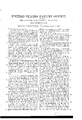
- A represents a steam tight, pressure chamber, formed by securing at their edges, two elastic metallic disks B, O, one upon either side of a metallic ring D.
- a shank or stem E To the ring D, is attached a shank or stem E through which is anopening F, as shown in Fig. 3, by means of which communication is made between the pressure chamber A, and the steam boiler, or other vessel containing pressure.
- P, P, P, P are 4t legs, their purpose being to secure the exterior case to the instrument.
- G, H are bars extending across the face of the disks B, O.
- the bar G is firmly .attached at its center to the center of the disk B.
- the bar H extends across the face of disk C, but at some little distance therefrom.
- the two bars Gr, H are connected at their ends by means of studs I, I, so that one motion is common to both.
- a tongue or half nut M On the inner side of the bar H, is a tongue or half nut M, one end of which is seated into the spiral groove of the spindle L, but left suticiently free to the motion of the spindle L, that no unnecessary friction shall be caused thereby.
- N is a spring, its use being to antagonize the rotary motion of the spindle L, and keep its point at all times in contact with the face of disk O.
- O is an index attached to the outer end of spindle L, and by its position in reference to the graduations upon the index plate R, indicates the amount of pressure to which the instrument may be subjected.
- S represents the exterior case of the instrument, and is shown in section in Fig. 3.
- the disk C in its outward ginotion, presses against and moves also thel Aspindle L as the spindle L 1n its outward motion, presses against the tongue or half" nut M, which in its turn partakes of a directly contrary motion to that of spindle L (M, being attached to bar H, as before described) it follows, that a rotary mot-ion is imparted to spindle L: the sum of which rotary motion, depends upon the combined outward action of the disks B, O, and the pitch of thread which is made upon spindle L. Index O is attached to the outer end of spindle L, and motion communicated to it thereby.
- index O in reference to the graduations upon the face of the instrument, indicates the amount of pressure in pounds per square inch, to which the instrument may be subjected. It will also be seen that my improved gage as i io What I do claim and desire to secure by Letters Patent is- The combined arrangement of the duplicate elastic metallic disks B, C, With the bars G, H, as described, for the purpose of giving motion to the index O, in the manner and for Jche purpose herein described.
Description
J. E. WUOTTEN.
Pressure Gage.
Patented Nov. 17, 1857.
UNITED STATES PATENT OFFICE.
JOI-IN E. WOOTTEN, OF PHILADELPHIA, PENNSYLVANIA.
STEAM-PRESSURE GAG-E.
Speccation of Letters Patent No. 18,655, dated November 17, 1857.
To all whom it may concern:
Be it known that I, JOHN E. IVOOTTEN, of the city and county of Philadelphia and State of Pennsylvania, have invented a new and Improved Mode of Constructing Steam- Pressure Gages; and I do hereby declare that the following is a full and exact description thereof, reference being had to the accompanying drawings, making a part of this specification, in which- Figure l is a perspective view, with the exterior case removed, showing the arrangement of the working parts. Fig. 2 is a front View of the instrument, showing the graduated face, and index. Fig. 3 is a longitudinal section showing the pressure chamber; of which a description will be hereafter given. Fig. 4L is a top view of the working parts, the exterior case being removed, similar letters of reference referring to similar parts.
A represents a steam tight, pressure chamber, formed by securing at their edges, two elastic metallic disks B, O, one upon either side of a metallic ring D. To the ring D, is attached a shank or stem E through which is anopening F, as shown in Fig. 3, by means of which communication is made between the pressure chamber A, and the steam boiler, or other vessel containing pressure.
P, P, P, P are 4t legs, their purpose being to secure the exterior case to the instrument.
G, H, are bars extending across the face of the disks B, O. The bar G is firmly .attached at its center to the center of the disk B. The bar H extends across the face of disk C, but at some little distance therefrom. The two bars Gr, H, are connected at their ends by means of studs I, I, so that one motion is common to both.
K, is a stand attached to bar H, its purpose being to sustain the spindle L, steadily in its position. At the end of stand K, and directly in line with the center of disk O, is pierced al small round hole. In the same line, is pierced another hole of same size through the center of bar H. These holes should be of such size, that the spindle L, shall be held within them steadily, and at the same time be free to revolve with as little friction as possible. One end of spindle L is brought into contact with disk C, near which end of spindle L, is cut a spiral groove or thread of sufficiently coarse pitch,
that the application of a rectilinear motion against the thread will impart a rotary motion to the spindle L.
On the inner side of the bar H, is a tongue or half nut M, one end of which is seated into the spiral groove of the spindle L, but left suticiently free to the motion of the spindle L, that no unnecessary friction shall be caused thereby.
N, is a spring, its use being to antagonize the rotary motion of the spindle L, and keep its point at all times in contact with the face of disk O.
O, is an index attached to the outer end of spindle L, and by its position in reference to the graduations upon the index plate R, indicates the amount of pressure to which the instrument may be subjected.
S represents the exterior case of the instrument, and is shown in section in Fig. 3.
Having thus described the various parts of my improved pressure gage, I will proceed to explain its application and mode of operation which is as follows: The instrument should be connected at the shank or stem E, with the steam boiler or other vessel sustaining pressure, and communication therewith be open to the pressure chamber, by means of the channel F. Then pressure exceeding that of the atmosphere, is admitted to the chamber A, the disks B, O, are forced outward until the internal pressure is balanced by their resisting strain. Disk B, carries with it bar Gr, which by its end connections with bar H, move it also, in same: direction. The disk C in its outward ginotion, presses against and moves also thel Aspindle L as the spindle L 1n its outward motion, presses against the tongue or half" nut M, which in its turn partakes of a directly contrary motion to that of spindle L (M, being attached to bar H, as before described) it follows, that a rotary mot-ion is imparted to spindle L: the sum of which rotary motion, depends upon the combined outward action of the disks B, O, and the pitch of thread which is made upon spindle L. Index O is attached to the outer end of spindle L, and motion communicated to it thereby. The position of index O, in reference to the graduations upon the face of the instrument, indicates the amount of pressure in pounds per square inch, to which the instrument may be subjected. It will also be seen that my improved gage as i io What I do claim and desire to secure by Letters Patent is- The combined arrangement of the duplicate elastic metallic disks B, C, With the bars G, H, as described, for the purpose of giving motion to the index O, in the manner and for Jche purpose herein described.
J. E. WOOTTEN.
Witnesses: p
W. A. BOYD, W. N. REIGLE.
Publications (1)
| Publication Number | Publication Date |
|---|---|
| US18655A true US18655A (en) | 1857-11-17 |
Family
ID=2082146
Family Applications (1)
| Application Number | Title | Priority Date | Filing Date |
|---|---|---|---|
| US18655D Expired - Lifetime US18655A (en) | Steam-pressure gage |
Country Status (1)
| Country | Link |
|---|---|
| US (1) | US18655A (en) |
Cited By (1)
| Publication number | Priority date | Publication date | Assignee | Title |
|---|---|---|---|---|
| US2437371A (en) * | 1944-02-04 | 1948-03-09 | Stewart Warner Corp | Absolute pressure gauge |
-
0
- US US18655D patent/US18655A/en not_active Expired - Lifetime
Cited By (1)
| Publication number | Priority date | Publication date | Assignee | Title |
|---|---|---|---|---|
| US2437371A (en) * | 1944-02-04 | 1948-03-09 | Stewart Warner Corp | Absolute pressure gauge |
Similar Documents
| Publication | Publication Date | Title |
|---|---|---|
| US18655A (en) | Steam-pressure gage | |
| US18129A (en) | Tube fob steam-pressure gages | |
| US18526A (en) | Steam-pressure gkage | |
| US25959A (en) | duckworth | |
| US22235A (en) | Improvement in horse-rakes | |
| US25132A (en) | Eotary movement | |
| US12022A (en) | Kotaky pump | |
| US21435A (en) | Calipers and dividers | |
| US16938A (en) | Method osi constrtrctorg bit-stocks | |
| US14286A (en) | Francis i | |
| US17607A (en) | miller and j | |
| US19177A (en) | Moses m | |
| US14243A (en) | Weeuch | |
| US22403A (en) | Improved ice-pick | |
| US15992A (en) | Metallic pen | |
| US22157A (en) | Pipe-tongs | |
| US14170A (en) | Screw-jack | |
| US17988A (en) | wells | |
| US20744A (en) | Propeller | |
| US13998A (en) | Extension-bit | |
| US18245A (en) | Isaac hermann | |
| US22984A (en) | Coitvebting eecipbocating into rotary motion | |
| US19041A (en) | Improvement in cotton-gins | |
| US13623A (en) | reynolds | |
| US91072A (en) | Improved ratchet-feed |