RU2770121C2 - Multicore fiber for multipoint laser probe - Google Patents
Multicore fiber for multipoint laser probe Download PDFInfo
- Publication number
- RU2770121C2 RU2770121C2 RU2020122402A RU2020122402A RU2770121C2 RU 2770121 C2 RU2770121 C2 RU 2770121C2 RU 2020122402 A RU2020122402 A RU 2020122402A RU 2020122402 A RU2020122402 A RU 2020122402A RU 2770121 C2 RU2770121 C2 RU 2770121C2
- Authority
- RU
- Russia
- Prior art keywords
- mcf
- laser
- distal end
- probe
- lens
- Prior art date
Links
- 239000000523 sample Substances 0.000 title claims abstract description 155
- 239000000835 fiber Substances 0.000 title abstract description 55
- 239000011248 coating agent Substances 0.000 claims abstract description 33
- 238000000576 coating method Methods 0.000 claims abstract description 33
- 230000005855 radiation Effects 0.000 claims abstract description 27
- 239000013307 optical fiber Substances 0.000 claims abstract description 13
- 230000003287 optical effect Effects 0.000 claims description 31
- 230000001681 protective effect Effects 0.000 claims description 24
- 238000000034 method Methods 0.000 claims description 22
- VYPSYNLAJGMNEJ-UHFFFAOYSA-N Silicium dioxide Chemical compound O=[Si]=O VYPSYNLAJGMNEJ-UHFFFAOYSA-N 0.000 claims description 19
- 238000005286 illumination Methods 0.000 claims description 18
- 239000005350 fused silica glass Substances 0.000 claims description 8
- 235000012239 silicon dioxide Nutrition 0.000 claims description 5
- 239000000377 silicon dioxide Substances 0.000 claims description 5
- 230000005540 biological transmission Effects 0.000 claims description 4
- 238000005253 cladding Methods 0.000 claims description 3
- 229920000642 polymer Polymers 0.000 claims 8
- 230000000694 effects Effects 0.000 abstract 1
- 239000000126 substance Substances 0.000 abstract 1
- 239000000463 material Substances 0.000 description 18
- 210000001525 retina Anatomy 0.000 description 12
- 239000004642 Polyimide Substances 0.000 description 7
- 238000004519 manufacturing process Methods 0.000 description 7
- 229920001721 polyimide Polymers 0.000 description 7
- 230000008901 benefit Effects 0.000 description 6
- 230000000649 photocoagulation Effects 0.000 description 6
- 229910001220 stainless steel Inorganic materials 0.000 description 5
- 239000010935 stainless steel Substances 0.000 description 5
- 239000000853 adhesive Substances 0.000 description 4
- 230000001070 adhesive effect Effects 0.000 description 4
- -1 for example Substances 0.000 description 4
- 229910001000 nickel titanium Inorganic materials 0.000 description 4
- HLXZNVUGXRDIFK-UHFFFAOYSA-N nickel titanium Chemical compound [Ti].[Ti].[Ti].[Ti].[Ti].[Ti].[Ti].[Ti].[Ti].[Ti].[Ti].[Ni].[Ni].[Ni].[Ni].[Ni].[Ni].[Ni].[Ni].[Ni].[Ni].[Ni].[Ni].[Ni].[Ni] HLXZNVUGXRDIFK-UHFFFAOYSA-N 0.000 description 4
- BASFCYQUMIYNBI-UHFFFAOYSA-N platinum Chemical compound [Pt] BASFCYQUMIYNBI-UHFFFAOYSA-N 0.000 description 4
- 238000012546 transfer Methods 0.000 description 4
- 238000013461 design Methods 0.000 description 3
- 229910052594 sapphire Inorganic materials 0.000 description 3
- 239000010980 sapphire Substances 0.000 description 3
- PXHVJJICTQNCMI-UHFFFAOYSA-N Nickel Chemical compound [Ni] PXHVJJICTQNCMI-UHFFFAOYSA-N 0.000 description 2
- RTAQQCXQSZGOHL-UHFFFAOYSA-N Titanium Chemical compound [Ti] RTAQQCXQSZGOHL-UHFFFAOYSA-N 0.000 description 2
- 210000004204 blood vessel Anatomy 0.000 description 2
- 239000011521 glass Substances 0.000 description 2
- 238000003780 insertion Methods 0.000 description 2
- 230000037431 insertion Effects 0.000 description 2
- 229910052751 metal Inorganic materials 0.000 description 2
- 239000002184 metal Substances 0.000 description 2
- 238000012986 modification Methods 0.000 description 2
- 230000004048 modification Effects 0.000 description 2
- 238000013021 overheating Methods 0.000 description 2
- 238000000059 patterning Methods 0.000 description 2
- 230000002093 peripheral effect Effects 0.000 description 2
- 229910052697 platinum Inorganic materials 0.000 description 2
- 230000002207 retinal effect Effects 0.000 description 2
- 238000001356 surgical procedure Methods 0.000 description 2
- 230000001225 therapeutic effect Effects 0.000 description 2
- 239000010936 titanium Substances 0.000 description 2
- 229910052719 titanium Inorganic materials 0.000 description 2
- 230000004304 visual acuity Effects 0.000 description 2
- 230000016776 visual perception Effects 0.000 description 2
- NIXOWILDQLNWCW-UHFFFAOYSA-M Acrylate Chemical compound [O-]C(=O)C=C NIXOWILDQLNWCW-UHFFFAOYSA-M 0.000 description 1
- 229910001369 Brass Inorganic materials 0.000 description 1
- RYGMFSIKBFXOCR-UHFFFAOYSA-N Copper Chemical compound [Cu] RYGMFSIKBFXOCR-UHFFFAOYSA-N 0.000 description 1
- 206010012689 Diabetic retinopathy Diseases 0.000 description 1
- 206010025421 Macule Diseases 0.000 description 1
- XUIMIQQOPSSXEZ-UHFFFAOYSA-N Silicon Chemical compound [Si] XUIMIQQOPSSXEZ-UHFFFAOYSA-N 0.000 description 1
- BQCADISMDOOEFD-UHFFFAOYSA-N Silver Chemical compound [Ag] BQCADISMDOOEFD-UHFFFAOYSA-N 0.000 description 1
- 210000003484 anatomy Anatomy 0.000 description 1
- 230000015572 biosynthetic process Effects 0.000 description 1
- 239000010951 brass Substances 0.000 description 1
- 230000015556 catabolic process Effects 0.000 description 1
- 238000010276 construction Methods 0.000 description 1
- 239000000356 contaminant Substances 0.000 description 1
- 239000010949 copper Substances 0.000 description 1
- 229910052802 copper Inorganic materials 0.000 description 1
- 238000002788 crimping Methods 0.000 description 1
- 238000006731 degradation reaction Methods 0.000 description 1
- YXVFQADLFFNVDS-UHFFFAOYSA-N diammonium citrate Chemical compound [NH4+].[NH4+].[O-]C(=O)CC(O)(C(=O)O)CC([O-])=O YXVFQADLFFNVDS-UHFFFAOYSA-N 0.000 description 1
- 238000006073 displacement reaction Methods 0.000 description 1
- 238000005516 engineering process Methods 0.000 description 1
- 230000004438 eyesight Effects 0.000 description 1
- 230000006870 function Effects 0.000 description 1
- 229910052732 germanium Inorganic materials 0.000 description 1
- GNPVGFCGXDBREM-UHFFFAOYSA-N germanium atom Chemical compound [Ge] GNPVGFCGXDBREM-UHFFFAOYSA-N 0.000 description 1
- 238000010438 heat treatment Methods 0.000 description 1
- 239000003779 heat-resistant material Substances 0.000 description 1
- 230000001771 impaired effect Effects 0.000 description 1
- 150000002739 metals Chemical class 0.000 description 1
- 229910052759 nickel Inorganic materials 0.000 description 1
- 239000010453 quartz Substances 0.000 description 1
- 229910052710 silicon Inorganic materials 0.000 description 1
- 239000010703 silicon Substances 0.000 description 1
- 229910052709 silver Inorganic materials 0.000 description 1
- 239000004332 silver Substances 0.000 description 1
- 238000002560 therapeutic procedure Methods 0.000 description 1
- 210000003462 vein Anatomy 0.000 description 1
Images

Classifications
-
- A—HUMAN NECESSITIES
- A61—MEDICAL OR VETERINARY SCIENCE; HYGIENE
- A61F—FILTERS IMPLANTABLE INTO BLOOD VESSELS; PROSTHESES; DEVICES PROVIDING PATENCY TO, OR PREVENTING COLLAPSING OF, TUBULAR STRUCTURES OF THE BODY, e.g. STENTS; ORTHOPAEDIC, NURSING OR CONTRACEPTIVE DEVICES; FOMENTATION; TREATMENT OR PROTECTION OF EYES OR EARS; BANDAGES, DRESSINGS OR ABSORBENT PADS; FIRST-AID KITS
- A61F9/00—Methods or devices for treatment of the eyes; Devices for putting-in contact lenses; Devices to correct squinting; Apparatus to guide the blind; Protective devices for the eyes, carried on the body or in the hand
- A61F9/007—Methods or devices for eye surgery
- A61F9/008—Methods or devices for eye surgery using laser
- A61F9/00821—Methods or devices for eye surgery using laser for coagulation
-
- A—HUMAN NECESSITIES
- A61—MEDICAL OR VETERINARY SCIENCE; HYGIENE
- A61B—DIAGNOSIS; SURGERY; IDENTIFICATION
- A61B18/00—Surgical instruments, devices or methods for transferring non-mechanical forms of energy to or from the body
- A61B18/18—Surgical instruments, devices or methods for transferring non-mechanical forms of energy to or from the body by applying electromagnetic radiation, e.g. microwaves
- A61B18/20—Surgical instruments, devices or methods for transferring non-mechanical forms of energy to or from the body by applying electromagnetic radiation, e.g. microwaves using laser
- A61B18/22—Surgical instruments, devices or methods for transferring non-mechanical forms of energy to or from the body by applying electromagnetic radiation, e.g. microwaves using laser the beam being directed along or through a flexible conduit, e.g. an optical fibre; Couplings or hand-pieces therefor
- A61B18/24—Surgical instruments, devices or methods for transferring non-mechanical forms of energy to or from the body by applying electromagnetic radiation, e.g. microwaves using laser the beam being directed along or through a flexible conduit, e.g. an optical fibre; Couplings or hand-pieces therefor with a catheter
-
- A—HUMAN NECESSITIES
- A61—MEDICAL OR VETERINARY SCIENCE; HYGIENE
- A61B—DIAGNOSIS; SURGERY; IDENTIFICATION
- A61B90/00—Instruments, implements or accessories specially adapted for surgery or diagnosis and not covered by any of the groups A61B1/00 - A61B50/00, e.g. for luxation treatment or for protecting wound edges
- A61B90/30—Devices for illuminating a surgical field, the devices having an interrelation with other surgical devices or with a surgical procedure
-
- A—HUMAN NECESSITIES
- A61—MEDICAL OR VETERINARY SCIENCE; HYGIENE
- A61F—FILTERS IMPLANTABLE INTO BLOOD VESSELS; PROSTHESES; DEVICES PROVIDING PATENCY TO, OR PREVENTING COLLAPSING OF, TUBULAR STRUCTURES OF THE BODY, e.g. STENTS; ORTHOPAEDIC, NURSING OR CONTRACEPTIVE DEVICES; FOMENTATION; TREATMENT OR PROTECTION OF EYES OR EARS; BANDAGES, DRESSINGS OR ABSORBENT PADS; FIRST-AID KITS
- A61F9/00—Methods or devices for treatment of the eyes; Devices for putting-in contact lenses; Devices to correct squinting; Apparatus to guide the blind; Protective devices for the eyes, carried on the body or in the hand
- A61F9/007—Methods or devices for eye surgery
- A61F9/008—Methods or devices for eye surgery using laser
- A61F9/00821—Methods or devices for eye surgery using laser for coagulation
- A61F9/00823—Laser features or special beam parameters therefor
-
- B—PERFORMING OPERATIONS; TRANSPORTING
- B05—SPRAYING OR ATOMISING IN GENERAL; APPLYING FLUENT MATERIALS TO SURFACES, IN GENERAL
- B05C—APPARATUS FOR APPLYING FLUENT MATERIALS TO SURFACES, IN GENERAL
- B05C1/00—Apparatus in which liquid or other fluent material is applied to the surface of the work by contact with a member carrying the liquid or other fluent material, e.g. a porous member loaded with a liquid to be applied as a coating
- B05C1/02—Apparatus in which liquid or other fluent material is applied to the surface of the work by contact with a member carrying the liquid or other fluent material, e.g. a porous member loaded with a liquid to be applied as a coating for applying liquid or other fluent material to separate articles
- B05C1/022—Apparatus in which liquid or other fluent material is applied to the surface of the work by contact with a member carrying the liquid or other fluent material, e.g. a porous member loaded with a liquid to be applied as a coating for applying liquid or other fluent material to separate articles to the outer surface of hollow articles
-
- B—PERFORMING OPERATIONS; TRANSPORTING
- B05—SPRAYING OR ATOMISING IN GENERAL; APPLYING FLUENT MATERIALS TO SURFACES, IN GENERAL
- B05C—APPARATUS FOR APPLYING FLUENT MATERIALS TO SURFACES, IN GENERAL
- B05C1/00—Apparatus in which liquid or other fluent material is applied to the surface of the work by contact with a member carrying the liquid or other fluent material, e.g. a porous member loaded with a liquid to be applied as a coating
- B05C1/02—Apparatus in which liquid or other fluent material is applied to the surface of the work by contact with a member carrying the liquid or other fluent material, e.g. a porous member loaded with a liquid to be applied as a coating for applying liquid or other fluent material to separate articles
- B05C1/027—Apparatus in which liquid or other fluent material is applied to the surface of the work by contact with a member carrying the liquid or other fluent material, e.g. a porous member loaded with a liquid to be applied as a coating for applying liquid or other fluent material to separate articles only at particular parts of the articles
-
- G—PHYSICS
- G02—OPTICS
- G02B—OPTICAL ELEMENTS, SYSTEMS OR APPARATUS
- G02B27/00—Optical systems or apparatus not provided for by any of the groups G02B1/00 - G02B26/00, G02B30/00
- G02B27/10—Beam splitting or combining systems
- G02B27/1086—Beam splitting or combining systems operating by diffraction only
-
- G—PHYSICS
- G02—OPTICS
- G02B—OPTICAL ELEMENTS, SYSTEMS OR APPARATUS
- G02B6/00—Light guides; Structural details of arrangements comprising light guides and other optical elements, e.g. couplings
- G02B6/02—Optical fibres with cladding with or without a coating
- G02B6/02033—Core or cladding made from organic material, e.g. polymeric material
-
- G—PHYSICS
- G02—OPTICS
- G02B—OPTICAL ELEMENTS, SYSTEMS OR APPARATUS
- G02B6/00—Light guides; Structural details of arrangements comprising light guides and other optical elements, e.g. couplings
- G02B6/24—Coupling light guides
- G02B6/36—Mechanical coupling means
- G02B6/38—Mechanical coupling means having fibre to fibre mating means
- G02B6/3807—Dismountable connectors, i.e. comprising plugs
- G02B6/3833—Details of mounting fibres in ferrules; Assembly methods; Manufacture
- G02B6/3834—Means for centering or aligning the light guide within the ferrule
- G02B6/3843—Means for centering or aligning the light guide within the ferrule with auxiliary facilities for movably aligning or adjusting the fibre within its ferrule, e.g. measuring position or eccentricity
-
- G—PHYSICS
- G02—OPTICS
- G02B—OPTICAL ELEMENTS, SYSTEMS OR APPARATUS
- G02B6/00—Light guides; Structural details of arrangements comprising light guides and other optical elements, e.g. couplings
- G02B6/24—Coupling light guides
- G02B6/36—Mechanical coupling means
- G02B6/38—Mechanical coupling means having fibre to fibre mating means
- G02B6/3807—Dismountable connectors, i.e. comprising plugs
- G02B6/3833—Details of mounting fibres in ferrules; Assembly methods; Manufacture
- G02B6/3851—Ferrules having keying or coding means
-
- G—PHYSICS
- G02—OPTICS
- G02B—OPTICAL ELEMENTS, SYSTEMS OR APPARATUS
- G02B6/00—Light guides; Structural details of arrangements comprising light guides and other optical elements, e.g. couplings
- G02B6/24—Coupling light guides
- G02B6/36—Mechanical coupling means
- G02B6/38—Mechanical coupling means having fibre to fibre mating means
- G02B6/3807—Dismountable connectors, i.e. comprising plugs
- G02B6/3873—Connectors using guide surfaces for aligning ferrule ends, e.g. tubes, sleeves, V-grooves, rods, pins, balls
- G02B6/3885—Multicore or multichannel optical connectors, i.e. one single ferrule containing more than one fibre, e.g. ribbon type
-
- G—PHYSICS
- G02—OPTICS
- G02B—OPTICAL ELEMENTS, SYSTEMS OR APPARATUS
- G02B6/00—Light guides; Structural details of arrangements comprising light guides and other optical elements, e.g. couplings
- G02B6/24—Coupling light guides
- G02B6/42—Coupling light guides with opto-electronic elements
- G02B6/4201—Packages, e.g. shape, construction, internal or external details
- G02B6/4204—Packages, e.g. shape, construction, internal or external details the coupling comprising intermediate optical elements, e.g. lenses, holograms
-
- G—PHYSICS
- G02—OPTICS
- G02B—OPTICAL ELEMENTS, SYSTEMS OR APPARATUS
- G02B6/00—Light guides; Structural details of arrangements comprising light guides and other optical elements, e.g. couplings
- G02B6/24—Coupling light guides
- G02B6/42—Coupling light guides with opto-electronic elements
- G02B6/4296—Coupling light guides with opto-electronic elements coupling with sources of high radiant energy, e.g. high power lasers, high temperature light sources
-
- A—HUMAN NECESSITIES
- A61—MEDICAL OR VETERINARY SCIENCE; HYGIENE
- A61B—DIAGNOSIS; SURGERY; IDENTIFICATION
- A61B18/00—Surgical instruments, devices or methods for transferring non-mechanical forms of energy to or from the body
- A61B2018/00571—Surgical instruments, devices or methods for transferring non-mechanical forms of energy to or from the body for achieving a particular surgical effect
- A61B2018/00589—Coagulation
-
- A—HUMAN NECESSITIES
- A61—MEDICAL OR VETERINARY SCIENCE; HYGIENE
- A61B—DIAGNOSIS; SURGERY; IDENTIFICATION
- A61B18/00—Surgical instruments, devices or methods for transferring non-mechanical forms of energy to or from the body
- A61B2018/00636—Sensing and controlling the application of energy
- A61B2018/00773—Sensed parameters
- A61B2018/00779—Power or energy
-
- A—HUMAN NECESSITIES
- A61—MEDICAL OR VETERINARY SCIENCE; HYGIENE
- A61B—DIAGNOSIS; SURGERY; IDENTIFICATION
- A61B18/00—Surgical instruments, devices or methods for transferring non-mechanical forms of energy to or from the body
- A61B18/18—Surgical instruments, devices or methods for transferring non-mechanical forms of energy to or from the body by applying electromagnetic radiation, e.g. microwaves
- A61B18/20—Surgical instruments, devices or methods for transferring non-mechanical forms of energy to or from the body by applying electromagnetic radiation, e.g. microwaves using laser
- A61B2018/2015—Miscellaneous features
- A61B2018/2025—Miscellaneous features with a pilot laser
-
- A—HUMAN NECESSITIES
- A61—MEDICAL OR VETERINARY SCIENCE; HYGIENE
- A61B—DIAGNOSIS; SURGERY; IDENTIFICATION
- A61B18/00—Surgical instruments, devices or methods for transferring non-mechanical forms of energy to or from the body
- A61B18/18—Surgical instruments, devices or methods for transferring non-mechanical forms of energy to or from the body by applying electromagnetic radiation, e.g. microwaves
- A61B18/20—Surgical instruments, devices or methods for transferring non-mechanical forms of energy to or from the body by applying electromagnetic radiation, e.g. microwaves using laser
- A61B2018/2065—Multiwave; Wavelength mixing, e.g. using four or more wavelengths
-
- A—HUMAN NECESSITIES
- A61—MEDICAL OR VETERINARY SCIENCE; HYGIENE
- A61B—DIAGNOSIS; SURGERY; IDENTIFICATION
- A61B18/00—Surgical instruments, devices or methods for transferring non-mechanical forms of energy to or from the body
- A61B18/18—Surgical instruments, devices or methods for transferring non-mechanical forms of energy to or from the body by applying electromagnetic radiation, e.g. microwaves
- A61B18/20—Surgical instruments, devices or methods for transferring non-mechanical forms of energy to or from the body by applying electromagnetic radiation, e.g. microwaves using laser
- A61B2018/208—Surgical instruments, devices or methods for transferring non-mechanical forms of energy to or from the body by applying electromagnetic radiation, e.g. microwaves using laser with multiple treatment beams not sharing a common path, e.g. non-axial or parallel
-
- A—HUMAN NECESSITIES
- A61—MEDICAL OR VETERINARY SCIENCE; HYGIENE
- A61B—DIAGNOSIS; SURGERY; IDENTIFICATION
- A61B18/00—Surgical instruments, devices or methods for transferring non-mechanical forms of energy to or from the body
- A61B18/18—Surgical instruments, devices or methods for transferring non-mechanical forms of energy to or from the body by applying electromagnetic radiation, e.g. microwaves
- A61B18/20—Surgical instruments, devices or methods for transferring non-mechanical forms of energy to or from the body by applying electromagnetic radiation, e.g. microwaves using laser
- A61B18/22—Surgical instruments, devices or methods for transferring non-mechanical forms of energy to or from the body by applying electromagnetic radiation, e.g. microwaves using laser the beam being directed along or through a flexible conduit, e.g. an optical fibre; Couplings or hand-pieces therefor
- A61B2018/2205—Characteristics of fibres
- A61B2018/2211—Plurality of fibres
-
- A—HUMAN NECESSITIES
- A61—MEDICAL OR VETERINARY SCIENCE; HYGIENE
- A61B—DIAGNOSIS; SURGERY; IDENTIFICATION
- A61B18/00—Surgical instruments, devices or methods for transferring non-mechanical forms of energy to or from the body
- A61B18/18—Surgical instruments, devices or methods for transferring non-mechanical forms of energy to or from the body by applying electromagnetic radiation, e.g. microwaves
- A61B18/20—Surgical instruments, devices or methods for transferring non-mechanical forms of energy to or from the body by applying electromagnetic radiation, e.g. microwaves using laser
- A61B18/22—Surgical instruments, devices or methods for transferring non-mechanical forms of energy to or from the body by applying electromagnetic radiation, e.g. microwaves using laser the beam being directed along or through a flexible conduit, e.g. an optical fibre; Couplings or hand-pieces therefor
- A61B2018/2255—Optical elements at the distal end of probe tips
- A61B2018/2266—Optical elements at the distal end of probe tips with a lens, e.g. ball tipped
-
- A—HUMAN NECESSITIES
- A61—MEDICAL OR VETERINARY SCIENCE; HYGIENE
- A61B—DIAGNOSIS; SURGERY; IDENTIFICATION
- A61B18/00—Surgical instruments, devices or methods for transferring non-mechanical forms of energy to or from the body
- A61B18/18—Surgical instruments, devices or methods for transferring non-mechanical forms of energy to or from the body by applying electromagnetic radiation, e.g. microwaves
- A61B18/20—Surgical instruments, devices or methods for transferring non-mechanical forms of energy to or from the body by applying electromagnetic radiation, e.g. microwaves using laser
- A61B18/22—Surgical instruments, devices or methods for transferring non-mechanical forms of energy to or from the body by applying electromagnetic radiation, e.g. microwaves using laser the beam being directed along or through a flexible conduit, e.g. an optical fibre; Couplings or hand-pieces therefor
- A61B2018/2255—Optical elements at the distal end of probe tips
- A61B2018/2294—Optical elements at the distal end of probe tips with a diffraction grating
-
- A—HUMAN NECESSITIES
- A61—MEDICAL OR VETERINARY SCIENCE; HYGIENE
- A61B—DIAGNOSIS; SURGERY; IDENTIFICATION
- A61B90/00—Instruments, implements or accessories specially adapted for surgery or diagnosis and not covered by any of the groups A61B1/00 - A61B50/00, e.g. for luxation treatment or for protecting wound edges
- A61B90/30—Devices for illuminating a surgical field, the devices having an interrelation with other surgical devices or with a surgical procedure
- A61B2090/306—Devices for illuminating a surgical field, the devices having an interrelation with other surgical devices or with a surgical procedure using optical fibres
-
- A—HUMAN NECESSITIES
- A61—MEDICAL OR VETERINARY SCIENCE; HYGIENE
- A61F—FILTERS IMPLANTABLE INTO BLOOD VESSELS; PROSTHESES; DEVICES PROVIDING PATENCY TO, OR PREVENTING COLLAPSING OF, TUBULAR STRUCTURES OF THE BODY, e.g. STENTS; ORTHOPAEDIC, NURSING OR CONTRACEPTIVE DEVICES; FOMENTATION; TREATMENT OR PROTECTION OF EYES OR EARS; BANDAGES, DRESSINGS OR ABSORBENT PADS; FIRST-AID KITS
- A61F9/00—Methods or devices for treatment of the eyes; Devices for putting-in contact lenses; Devices to correct squinting; Apparatus to guide the blind; Protective devices for the eyes, carried on the body or in the hand
- A61F9/007—Methods or devices for eye surgery
- A61F9/008—Methods or devices for eye surgery using laser
- A61F2009/00861—Methods or devices for eye surgery using laser adapted for treatment at a particular location
- A61F2009/00863—Retina
-
- G—PHYSICS
- G02—OPTICS
- G02B—OPTICAL ELEMENTS, SYSTEMS OR APPARATUS
- G02B6/00—Light guides; Structural details of arrangements comprising light guides and other optical elements, e.g. couplings
- G02B6/02—Optical fibres with cladding with or without a coating
- G02B6/02042—Multicore optical fibres
-
- G—PHYSICS
- G02—OPTICS
- G02B—OPTICAL ELEMENTS, SYSTEMS OR APPARATUS
- G02B6/00—Light guides; Structural details of arrangements comprising light guides and other optical elements, e.g. couplings
- G02B6/24—Coupling light guides
- G02B6/42—Coupling light guides with opto-electronic elements
- G02B6/4201—Packages, e.g. shape, construction, internal or external details
- G02B6/4204—Packages, e.g. shape, construction, internal or external details the coupling comprising intermediate optical elements, e.g. lenses, holograms
- G02B6/4206—Optical features
Landscapes
- Health & Medical Sciences (AREA)
- Physics & Mathematics (AREA)
- Optics & Photonics (AREA)
- Surgery (AREA)
- Life Sciences & Earth Sciences (AREA)
- Ophthalmology & Optometry (AREA)
- Animal Behavior & Ethology (AREA)
- Biomedical Technology (AREA)
- Heart & Thoracic Surgery (AREA)
- Nuclear Medicine, Radiotherapy & Molecular Imaging (AREA)
- General Health & Medical Sciences (AREA)
- Public Health (AREA)
- Veterinary Medicine (AREA)
- Engineering & Computer Science (AREA)
- General Physics & Mathematics (AREA)
- Vascular Medicine (AREA)
- Medical Informatics (AREA)
- Molecular Biology (AREA)
- Otolaryngology (AREA)
- Electromagnetism (AREA)
- Oral & Maxillofacial Surgery (AREA)
- Pathology (AREA)
- Laser Surgery Devices (AREA)
- Endoscopes (AREA)
- Dental Tools And Instruments Or Auxiliary Dental Instruments (AREA)
- Radiation-Therapy Devices (AREA)
- Optical Couplings Of Light Guides (AREA)
Abstract
Description
ОБЛАСТЬ ТЕХНИКИ, К КОТОРОЙ ОТНОСИТСЯ ИЗОБРЕТЕНИЕFIELD OF TECHNOLOGY TO WHICH THE INVENTION RELATES
[1] Настоящее изобретение относится к многоточечному лазерному зонду и, в частности, к системам и способам подачи многоточечных лазерных пучков излучения через хирургический зонд, имеющий многожильный оптоволоконный кабель. [1] The present invention relates to a multi-point laser probe and, in particular, to systems and methods for delivering multi-point laser beams of radiation through a surgical probe having a multi-core fiber optic cable.
УРОВЕНЬ ТЕХНИКИBACKGROUND OF THE INVENTION
[2] В широком спектре медицинских процедур лазерное излучение используется для помощи при операции и для лечения организма пациента. Например, при лазерной фотокоагуляции лазерный зонд используется для прижигания кровеносных сосудов в точках прижигания лазером по сетчатке. Определенные типы лазерных зондов прижигают несколько точек одновременно, что может обеспечить более быструю и эффективную фотокоагуляцию. Некоторые из этих многоточечных лазерных зондов разделяют один лазерный пучок на множество лазерных пучков, что демонстрирует рисунок лазерных точек, и подают пучки на массив оптических волокон, что демонстрирует соответствующий рисунок волокон. Как правило, волокна должны быть плотно уложены, чтобы рисунок волокон совпадал с рисунком лазерных точек. Более того, рисунок лазерных точек должен быть точно выровнен с рисунком волокон.[2] In a wide range of medical procedures, laser radiation is used to assist in surgery and to treat the patient's body. For example, in laser photocoagulation, a laser probe is used to cauterize blood vessels at the laser cauterization points on the retina. Certain types of laser probes cauterize multiple points at the same time, which can provide faster and more efficient photocoagulation. Some of these multipoint laser probes split one laser beam into a plurality of laser beams, showing the laser dot pattern, and apply the beams to an array of optical fibers, showing the corresponding fiber pattern. As a general rule, the fibers must be tightly packed so that the pattern of the fibers matches the pattern of the laser dots. Moreover, the pattern of the laser dots must be precisely aligned with the pattern of the fibers.
[3] В дополнение к прижиганию кровеносных сосудов в точках прижигания лазером лазер также может повреждать некоторое количество палочек и колбочек, которые присутствуют в сетчатке, которые обеспечивают зрительное восприятие, что негативно влияет на остроту зрения. Поскольку зрительное восприятие является наиболее острым в центральной части макулы сетчатки, хирург приспосабливает лазерный зонд для образования точек прижигания лазером на периферийных участках сетчатки. Таким образом, могут пожертвовать некоторой остротой периферического зрения для сохранения центрального зрения. Во время операции хирург запускает зонд с неприжигающим направляющим пучком так, что область сетчатки, подлежащая фотокоагуляции, освещается. Вследствие доступности инфракрасных лазерных диодов малой мощности направляющий пучок, как правило, представляет собой инфракрасное лазерное излучение малой мощности. После того, как хирург установил лазерный зонд так, чтобы освещать требуемую точку на сетчатке, хирург активирует лазер посредством ножной педали или других средств, чтобы затем фотокоагулировать освещенный участок. После прижигания точки на сетчатке хирург перемещает зонд для освещения новой точки направляющим пучком, активирует лазер, перемещает зонд и т. д. пока требуемое количество точек прижигания лазером не распределят по сетчатке.[3] In addition to cauterizing blood vessels at laser burn points, the laser can also damage some of the rods and cones that are present in the retina, which provide visual perception, which negatively affects visual acuity. Since visual perception is sharpest in the central part of the retinal macula, the surgeon adjusts the laser probe to generate laser cauterization points in the peripheral areas of the retina. Thus, some peripheral visual acuity may be sacrificed to preserve central vision. During the operation, the surgeon fires a probe with a non-cauterizing guiding beam so that the area of the retina to be photocoagulated is illuminated. Due to the availability of low power infrared laser diodes, the guide beam is typically low power infrared laser light. After the surgeon has positioned the laser probe to illuminate a desired point on the retina, the surgeon activates the laser via a foot pedal or other means to then photocoagulate the illuminated area. After cauterizing a point on the retina, the surgeon moves the probe to illuminate the new point with the guiding beam, activates the laser, moves the probe, etc. until the required number of laser cauterization points have been distributed over the retina.
[4] В случае диабетической ретинопатии может выполняться процедура панретинальной фотокоагуляции (PRP), и количество требуемых манипуляций лазерной фотокоагуляции для PRP, как правило, является большим. Например, обычно прижигают от 1000 до 1500 точек. Таким образом, будет очевидно, что, если бы лазерный зонд представлял собой многоточечный зонд, обеспечивающий прижигание нескольких точек одновременно, процедура фотокоагуляции проводилась бы быстрее (при условии, что мощность лазерного источника является достаточной). Соответственно многоточечные/многоволоконные лазерные зонды разработаны и описаны в патентах США № 8951244 и 8561280, которые включены в настоящий документ посредством ссылки во всей своей полноте.[4] In the case of diabetic retinopathy, a panretinal photocoagulation (PRP) procedure can be performed, and the number of laser photocoagulation procedures required for PRP is generally large. For example, usually cauterized from 1000 to 1500 points. Thus, it will be obvious that if the laser probe were a multi-point probe, providing cauterization of several points at the same time, the photocoagulation procedure would be carried out faster (provided that the power of the laser source is sufficient). Accordingly, multi-point/multi-fiber laser probes are developed and described in US Pat. Nos. 8,951,244 and 8,561,280, which are incorporated herein by reference in their entirety.
[5] Для витреоретинальных процедур также является преимущественным освещающее световое излучение, направленное в глаз и на ткань сетчатки. Часто хирурги, выполняющие витреоретинальные процедуры, используют лазерный зонд для подачи лазерных направляющих пучков и лазерных терапевтических пучков, а также используют дополнительный инструмент для направления освещающего пучка излучения на поверхность сетчатки для рассмотрения анатомической структуры пациента.[5] For vitreoretinal procedures, illuminating light directed to the eye and retinal tissue is also advantageous. Often surgeons performing vitreoretinal procedures use a laser probe to deliver laser guiding beams and laser therapeutic beams, and use an additional instrument to direct an illuminating beam of radiation to the surface of the retina to view the patient's anatomy.
КРАТКОЕ ОПИСАНИЕSHORT DESCRIPTION
[6] Согласно одному варианту осуществления настоящее изобретение относится к многоточечному лазерному зонду, который содержит основную часть зонда, которая имеет форму и размеры, позволяющие захват пользователем; наконечник зонда, содержащий канюлю, выполненную с возможностью введения в глаз; градиентную линзу (GRIN), расположенную в канюле в части ее дистального конца; и многожильный оптоволоконный кабель (MCF), проходящий по меньшей мере частично через канюлю. MCF может содержать множество жил, выполненных из диоксида кремния, легированного германием; оболочку, выполненную из плавленого диоксида кремния; покрытие, окружающее оболочку; и дистальный конец, расположенный у поверхности контакта с линзой GRIN. Оболочка может окружать множество жил. Показатель преломления одной или более из множества жил может быть больше показателя преломления оболочки. На длине дистального конца MCF может быть исключен участок покрытия, и линза GRIN может быть выполнена с возможностью переноса лазерного излучения с дистального конца MCF для создания многоточечного рисунка лазерных пучков на целевой поверхности.[6] According to one embodiment, the present invention relates to a multi-point laser probe, which includes a probe main body that is shaped and sized to be gripped by a user; a probe tip containing a cannula capable of being inserted into the eye; a gradient lens (GRIN) located in the cannula in part of its distal end; and a multi-core fiber optic cable (MCF) extending at least partially through the cannula. The MCF may comprise a plurality of germanium-doped silica strands; a shell made of fused silica; coating surrounding the shell; and a distal end located at the GRIN lens contact surface. The shell may surround a plurality of veins. The refractive index of one or more of the plurality of strands may be greater than the refractive index of the sheath. The length of the distal end of the MCF may be omitted, and the GRIN lens may be configured to transfer laser light from the distal end of the MCF to create a multi-point pattern of laser beams on the target surface.
[7] Другой вариант осуществления относится к многоточечному лазерному зонду, который содержит MCF, содержащий множество жил, окруженных оболочкой, и покрытие, окружающее оболочку и зонд. Зонд может содержать наконечник зонда, соединенный с дистальным концом MCF. Многоточечный лазерный зонд также может содержать линзу, расположенную на дистальном конце наконечника зонда. Линза может быть выполнена с возможностью переноса лазерного излучения с дистального конца MCF для создания многоточечного рисунка лазерных пучков на целевой поверхности. Дистальный конец MCF может заканчиваться у поверхности контакта с линзой. Показатель преломления одной или более из множества жил может быть больше показателя преломления оболочки.[7] Another embodiment relates to a multipoint laser probe that includes an MCF containing a plurality of strands surrounded by a sheath and a coating surrounding the sheath and probe. The probe may include a probe tip connected to the distal end of the MCF. The multipoint laser probe may also include a lens located at the distal end of the probe tip. The lens may be configured to transmit laser light from the distal end of the MCF to create a multi-point pattern of laser beams on the target surface. The distal end of the MCF may terminate at the lens contact surface. The refractive index of one or more of the plurality of strands may be greater than the refractive index of the sheath.
[8] Еще один вариант осуществления относится к способу подачи многоточечного рисунка лазерного пучка. Способ может включать генерирование лазерного пучка излучения посредством лазерного источника; коллимацию лазерного пучка излучения; направление коллимированного лазерного пучка излучения на дифракционный оптический элемент (DOE), выполненный с возможностью создания многоточечного рисунка лазера для лазерного пучка излучения; и фокусирование многоточечного рисунка лазерного пучка излучения на плоскость поверхности контакта проксимального конца MCF. Каждый из лазерного пучка излучения в многоточечном рисунке лазера для лазерных пучков излучения может быть передан в одну из множества жил MCF. Лазерные пучки излучения могут быть переданы по жилам MCF. Множество жил могут быть окружены оболочкой, и при этом оболочка может быть окружена покрытием. Показатель преломления каждой из множества жил может быть больше показателя преломления оболочки, и на длине дистального конца MCF может быть исключен участок покрытия. Способ также может включать передачу многоточечного рисунка лазерных пучков излучения на дистальный конец MCF и направление многоточечного рисунка лазерных пучков излучения через линзу на дистальном наконечнике хирургического зонда.[8] Another embodiment relates to a method for supplying a multi-point pattern of a laser beam. The method may include generating a laser beam of radiation through a laser source; collimation of the laser beam of radiation; directing the collimated laser beam onto a diffractive optical element (DOE) configured to create a multi-dot laser pattern for the laser beam; and focusing the multi-point pattern of the laser beam onto the plane of the contact surface of the proximal end of the MCF. Each of the laser beam in the multi-dot laser pattern for laser beams may be transmitted to one of the plurality of MCF strands. Laser beams of radiation can be transmitted along the MCF strands. A plurality of strands may be surrounded by a sheath, and the sheath may be surrounded by a coating. The refractive index of each of the plurality of strands may be greater than the refractive index of the sheath, and a coating portion may be omitted along the length of the distal end of the MCF. The method may also include transmitting a multi-dot pattern of laser beams to the distal end of the MCF and directing the multi-dot pattern of laser beams through a lens at the distal tip of the surgical probe.
[9] Различные варианты осуществления настоящего изобретения могут включать один или более из следующих признаков. Множество жил могут образовывать массив 2X2, который может быть выполнен с возможностью согласования с многоточечным рисунком 2X2 с дифракционного оптического элемента (DOE) лазерной системы. Дистальный конец MCF может примыкать к линзе GRIN с положительным давлением на поверхности контакта. Дистальный конец MCF может быть отделен от линзы GRIN посредством воздушного зазора. Участок части покрытия может быть удален с MCF, и этот участок может находиться в диапазоне от 0,5 мм до 5,0 мм, проходя проксимально от дистального конца MCF. Участок части покрытия, удаленный с MCF, может составлять от 1,0 мм до 3,0 мм, проходя проксимально от дистального конца MCF.[9] Various embodiments of the present invention may include one or more of the following features. The plurality of strands may form a 2X2 array that may be configured to match a 2X2 multi-dot pattern from a diffractive optical element (DOE) of a laser system. The distal end of the MCF may abut the GRIN lens with positive pressure on the contact surface. The distal end of the MCF may be separated from the GRIN lens by an air gap. A portion of the coating may be removed from the MCF and this portion may range from 0.5 mm to 5.0 mm extending proximally from the distal end of the MCF. The portion of the coating portion removed from the MCF may be 1.0 mm to 3.0 mm extending proximally from the distal end of the MCF.
[10] Различные варианты осуществления настоящего изобретения также могут включать один или более из следующих признаков. На длине дистального конца MCF может быть исключен участок покрытия. Длина покрытия, исключенного на длине дистального конца MCF, может составлять от 1,0 мм до 3,0 мм. Множество жил могут образовывать массив 2X2, выполненный с возможностью согласования с многоточечным рисунком 2X2 с дифракционного оптического элемента (DOE) лазерной системы. Линза может включать в себя линзу GRIN, и дистальный конец MCF может примыкать к линзе GRIN с положительным давлением. Линза может включать в себя линзу GRIN, и дистальный конец MCF может быть отделен от линзы GRIN посредством зазора. Наконечник зонда может содержать канюлю, выполненную с возможностью введения в глаз. Дистальный конец MCF и линза могут быть расположены в канюле. Может быть исключен участок покрытия на MCF, за счет чего улучшаются характеристики максимально допустимой мощности многоточечного лазерного зонда. Линза может быть расположена на дистальном конце наконечника зонда и может содержать линзу GRIN. Дистальный конец MCF может примыкать к линзе GRIN с положительным давлением. Дистальный конец MCF может быть отделен от линзы GRIN посредством воздушного зазора. Покрытие может включать в себя полиимидное покрытие. Множество жил могут содержать диоксид кремния, легированный германием. Оболочка может содержать плавленый диоксид кремния.[10] Various embodiments of the present invention may also include one or more of the following features. A patch of coverage may be omitted along the length of the distal end of the MCF. The length of the coating excluded along the length of the distal end of the MCF may be from 1.0 mm to 3.0 mm. The plurality of strands may form a 2X2 array configured to match a 2X2 multi-dot pattern from a diffractive optical element (DOE) of a laser system. The lens may include a GRIN lens and the distal end of the MCF may abut the positive pressure GRIN lens. The lens may include a GRIN lens and the distal end of the MCF may be separated from the GRIN lens by a gap. The probe tip may include a cannula capable of being inserted into the eye. The distal end of the MCF and the lens can be placed in the cannula. The coverage area on the MCF can be eliminated, thereby improving the maximum power capability of the multipoint laser probe. The lens may be located at the distal end of the probe tip and may include a GRIN lens. The distal end of the MCF may be adjacent to a positive pressure GRIN lens. The distal end of the MCF may be separated from the GRIN lens by an air gap. The coating may include a polyimide coating. Many strands may contain silicon dioxide doped with germanium. The shell may contain fused silica.
КРАТКОЕ ОПИСАНИЕ ГРАФИЧЕСКИХ МАТЕРИАЛОВBRIEF DESCRIPTION OF GRAPHICS
[11] Для более полного понимания настоящего изобретения, его признаков и его преимуществ далее осуществляется ссылка на следующее описание в сочетании с прилагаемыми графическими материалами, на которых:[11] For a more complete understanding of the present invention, its features and its advantages, reference is made to the following description in conjunction with the accompanying drawings, in which:
[12] на фиг. 1 показана примерная система для образования многоточечного рисунка лазерных пучков излучения для подачи на целевой участок хирургической операции в соответствии с конкретным вариантом осуществления настоящего изобретения;[12] in FIG. 1 shows an exemplary system for patterning laser beams for delivery to a surgical target site, in accordance with a specific embodiment of the present invention;
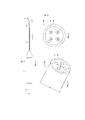
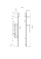
[13] на фиг. 2 показан примерный многоточечный лазерный зонд в соответствии с конкретным вариантом осуществления настоящего изобретения;[13] in FIG. 2 shows an exemplary multipoint laser probe in accordance with a specific embodiment of the present invention;
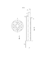
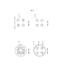
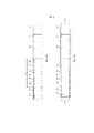
[14] на фиг. 3 и 4 показан конец примерного многожильного оптоволоконного кабеля (MCF) для использования с неосвещающими многоточечными лазерными зондами в соответствии с конкретным вариантом осуществления настоящего изобретения;[14] in FIG. 3 and 4 show the end of an exemplary multi-core fiber optic (MCF) cable for use with non-illuminating multipoint laser probes in accordance with a particular embodiment of the present invention;
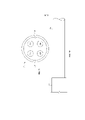
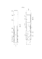
[15] на фиг. 5 показан конец примерного MCF для использования с освещающими многоточечными лазерными зондами в соответствии с конкретным вариантом осуществления настоящего изобретения;[15] in FIG. 5 shows the end of an exemplary MCF for use with illuminating multipoint laser probes in accordance with a particular embodiment of the present invention;
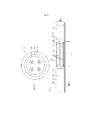
[16] на фиг. 6 показан подробный частичный вид в поперечном разрезе части дистального конца примерного многоточечного лазерного наконечника зонда в соответствии с конкретным вариантом осуществления настоящего изобретения;[16] in FIG. 6 is a detailed partial cross-sectional view of a portion of the distal end of an exemplary multipoint laser probe tip in accordance with a particular embodiment of the present invention;
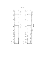
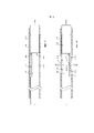
[17] на фиг. 7A-7F2 показаны различные аспекты многоточечных/многоволоконных лазерных зондов в сравнении с аспектами лазерных зондов с MCF для подчеркивания различных преимуществ и выгод лазерных зондов с многожильным волоконным кабелем в соответствии с конкретным вариантом осуществления настоящего изобретения;[17] in Fig. 7A-7F2 show various aspects of multi-point/multi-fiber laser probes in comparison with aspects of MCF laser probes to highlight the various advantages and benefits of multi-core fiber laser probes in accordance with a particular embodiment of the present invention;
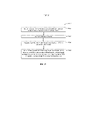
[18] на фиг. 8 показаны примерные действия, выполняемые хирургической лазерной системой в соответствии с конкретным вариантом осуществления настоящего изобретения; [18] in FIG. 8 shows exemplary actions performed by a surgical laser system in accordance with a specific embodiment of the present invention;
[19] на фиг. 9 показана часть дистального конца примерного многоточечного лазерного зонда, применяемого для образования многоточечного рисунка лазерных пучков излучения в соответствии с конкретным вариантом осуществления настоящего изобретения;[19] in FIG. 9 shows a portion of the distal end of an exemplary multipoint laser probe used to form a multipoint pattern of laser beams in accordance with a particular embodiment of the present invention;
[20] на фиг. 10 показана часть дистального конца другого примерного многоточечного лазерного зонда, в котором линза, имеющая выпуклые концы, расположена между дистальным концом MCF и защитным окном в соответствии с конкретным вариантом осуществления настоящего изобретения; [20] in FIG. 10 shows a portion of the distal end of another exemplary multipoint laser probe in which a lens having convex ends is positioned between the distal end of the MCF and a protective window, in accordance with a particular embodiment of the present invention;
[21] на фиг. 11 показан вид сбоку открытого конца примерного многоточечного лазерного зонда, показывающего открытый конец MCF, выровненный с линзой в соответствии с конкретным вариантом осуществления настоящего изобретения;[21] in FIG. 11 is a side view of the open end of an exemplary multipoint laser probe showing the open end of the MCF aligned with a lens in accordance with a particular embodiment of the present invention;
[22] на фиг. 12 показан открытый конец MCF, смещенный относительно линзы вследствие кольцевого зазора, образованного между MCF и внутренней стенкой канюли;[22] in FIG. 12 shows the open end of the MCF offset from the lens due to the annular gap formed between the MCF and the inner wall of the cannula;
[23] на фиг. 13 показано кольцо, которое расположено внутри кольцевого зазора, образованного вокруг внутренней оболочки MCF на его открытом конце, в соответствии с конкретным вариантом осуществления настоящего изобретения;[23] in FIG. 13 shows a ring that is located within the annular gap formed around the inner shell of the MCF at its open end, in accordance with a specific embodiment of the present invention;
[24] на фиг. 14 показана канюля другого примерного многоточечного лазерного зонда, которая имеет выточенное отверстие, в соответствии с конкретным вариантом осуществления настоящего изобретения;[24] in FIG. 14 shows a cannula of another exemplary multi-point laser probe that has a bore, in accordance with a particular embodiment of the present invention;
[25] на фиг. 15 показан примерный многоточечный лазерный зонд, в котором выравнивание открытого конца MCF обеспечивается за счет уменьшенного внутреннего диаметра канюли, в соответствии с конкретным вариантом осуществления настоящего изобретения;[25] in FIG. 15 shows an exemplary multipoint laser probe in which alignment of the open end of the MCF is provided by a reduced internal diameter of the cannula, in accordance with a particular embodiment of the present invention;
[26] на фиг. 16 показан потенциальный риск повреждения дистального конца MCF при сборке в соответствии с конкретным вариантом осуществления настоящего изобретения;[26] in FIG. 16 shows the potential risk of damage to the distal end of the MCF when assembled in accordance with a specific embodiment of the present invention;
[27] на фиг. 17 и 18 показано образование суженной части канюли примерного многоточечного лазерного зонда для сохранения выравнивания дистального конца MCF относительно линзы в соответствии с конкретным вариантом осуществления настоящего изобретения; [27] in FIG. 17 and 18 illustrate the formation of a constricted portion of the cannula of an exemplary multipoint laser probe to maintain alignment of the distal end of the MCF with a lens, in accordance with a particular embodiment of the present invention;
[28] на фиг. 19 показаны примерные действия для образования многоточечного лазерного зонда в соответствии с конкретным вариантом осуществления настоящего изобретения. [28] in FIG. 19 shows exemplary steps for forming a multipoint laser probe in accordance with a particular embodiment of the present invention.
ПОДРОБНОЕ ОПИСАНИЕDETAILED DESCRIPTION
[29] В следующем описании на примере изложены подробности для облегчения понимания раскрываемого объекта изобретения. Однако специалистам в данной области техники должно быть понятно, что раскрываемые варианты реализации являются иллюстративными и не исчерпывают все возможные варианты реализации. Таким образом, следует понимать, что ссылка на описанный пример не предназначена для ограничения объема настоящего изобретения. Любые изменения и дополнительные модификации в отношении описанных устройств, инструментов, способов, а также любое дополнительное применение принципов настоящего изобретения являются абсолютно возможными, что будет в общем очевидно специалисту в данной области техники, к которой относится настоящее изобретение. В частности, полностью предусмотрено, что признаки, компоненты и/или этапы, описанные относительно одного варианта осуществления, могут быть объединены с признаками, компонентами и/или этапами, описанными относительно других вариантов осуществления настоящего изобретения.[29] In the following description, by example, details are set forth to facilitate understanding of the disclosed subject matter. However, those skilled in the art will appreciate that the disclosed embodiments are illustrative and do not exhaust all possible implementations. Thus, it should be understood that reference to the described example is not intended to limit the scope of the present invention. Any changes and additional modifications in relation to the described devices, tools, methods, as well as any additional application of the principles of the present invention are absolutely possible, which will be generally obvious to a person skilled in the art to which the present invention pertains. In particular, it is fully contemplated that features, components and/or steps described with respect to one embodiment may be combined with features, components and/or steps described with respect to other embodiments of the present invention.
[30] В настоящем изобретении описаны освещающие и неосвещающие многожильные лазерные зонды, а также системы и способы, связанные с ними. На фиг. 1 показана примерная система 100 для создания многоточечного рисунка лазерных пучков излучения в соответствии с конкретными вариантами осуществления.[30] The present invention describes illuminating and non-illuminating multifilament laser probes, as well as systems and methods associated with them. In FIG. 1 shows an
[31] Система 100 представляет собой хирургическую лазерную систему 102, содержащую один или более лазерных источников для генерирования лазерных пучков, которая может использоваться при офтальмологической операции. Например, офтальмологическая хирургическая лазерная система 102 может альтернативно генерировать хирургический терапевтический пучок с первой длиной волны (например, ~532 нанометра (нм)) и лазерный направляющий пучок со второй длиной волны (например, ~635 нм). Пользователь, например, хирург или хирургический сотрудник, может управлять хирургической лазерной системой 102 (например, посредством ножной педали, голосовой команды и т. д.) для поочередного испускания лазерного направляющего пучка и выпускания терапевтического пучка для лечения организма пациента, например, выполнения фотокоагуляции. В некоторых случаях хирургическая лазерная система 102 может содержать порт, и лазерные пучки могут испускаться через порт в хирургической лазерной системе 102. Хирургическая лазерная система 102 может содержать адаптер порта лазерной системы, содержащий оптические элементы (не показаны) для образования многоточечного рисунка лазерных пучков излучения за счет лазерного пучка излучения из лазерного источника.[31] The
[32] Система 100 может подавать объединенный пучок излучения от порта на хирургический зонд 108 посредством многожильного оптоволоконного кабеля (MCF) 110. Зонд 108 может создавать многоточечный рисунок лазерных пучков излучения для подачи на сетчатку 120 глаза 125 пациента. Зонд 108 содержит основную часть 112 зонда и наконечник 140 зонда, который вмещает и защищает MCF 110. Часть 145 дистального конца наконечника 140 зонда также содержит линзу (не показана, более подробно описана ниже), которая переносит пучок излучения с дистального конца MCF 110 на сетчатку 120. [32] The
[33] Различные системы и способы могут быть использованы для создания многоточечного рисунка лазерных пучков излучения и объединения многоточечного рисунка лазерных пучков излучения с освещающим пучком излучения. В некоторых случаях адаптер порта может содержать оптические элементы, применяемые для создания многоточечного рисунка и/или объединенных пучков излучения а. В некоторых вариантах реализации хирургическая лазерная система 102 также может содержать охватывающий трубчатый порт (не показан), и адаптер порта может содержать втулку, которая выполняет функцию охватываемого соединителя для охватывающего трубчатого порта. Втулка может содержать отверстие, которое обеспечивает пропускание лазерного излучения из хирургической лазерной системы 102 и коллимацию одним или более оптическими элементами лазерного излучения, полученного из лазерного источника. В некоторых примерах оптический элемент во втулке может представлять собой градиентную (GRIN) линзу с длиной и углом наклона, выбранными таким образом, что оптический элемент коллимирует лазерное излучение, полученное в отверстие втулки на выбранном расстоянии, смежное с дифракционным оптическим элементом (DOE). В других примерах оптический элемент может представлять собой один из более других типов линз (например, сферическая, асферическая, двояковыпуклая стеклянная линза и т. д.). DOE может фокусировать многоточечный рисунок лазерных пучков излучения на плоскость поверхности контакта проксимального конца MCF, таким образом каждый из лазерных пучков излучения в многоточечном рисунке лазера лазерных пучков излучения передается по всей длине выбранной жилы из множества жил, содержащихся в MCF, на дистальный конец хирургического зонда. [33] Various systems and methods can be used to create a multi-dot pattern of laser beams and combine the multi-dot pattern of laser beams with an illuminating beam of radiation. In some cases, the port adapter may contain optical elements used to create a multi-dot pattern and/or combined beams of radiation a. In some embodiments, the
[34] При работе лазерный источник хирургической лазерной системы 102 генерирует лазерный пучок излучения. Коллиматорная оптика в хирургической лазерной системе 102 коллимирует лазерное излучение, направленное на дифракционный оптический элемент, выполненный с возможностью создания многоточечного рисунка лазерных пучков излучения. Многоточечный рисунок лазера затем направляют на конденсорную линзу и фокусирующую оптику хирургической лазерной системы 102 для фокусирования многоточечного рисунка на плоскость поверхности контакта проксимального конца MCF, таким образом каждый из лазерных пучков излучения в многоточечном рисунке лазера лазерных пучков излучения передается по всей длине выбранной жилы из множества жил, содержащихся в MCF 110. Многоточечный рисунок лазерных пучков излучения передается посредством MCF 110 на зонд 108, расположенный на дистальном конце MCF 110. Многоточечный рисунок лазерных пучков излучения входит в MCF 110 и передается через линзу на часть 145 дистального конца зонда 108. Многоточечный рисунок лазерных пучков излучения, входящий в зонд 108, может проецироваться на сетчатку 120 глаза 125.[34] In operation, the laser source of the
[35] На фиг. 2 более подробно показаны варианты осуществления наконечника 140 зонда по фиг. 1. Как описано выше, зонд 108 содержит основную часть 112 зонда, которая имеет форму и размеры, позволяющие захват пользователем. Наконечник 140 зонда, который содержит патрубок 251 и канюлю 250, проходит от основной части 112 зонда. Как показано, канюля 250 частично размещена в дистальном конце патрубка 251 и выходит за его пределы. В показанном примере наконечник 140 зонда имеет прямой участок 216 (например, патрубок 251 и прямую часть канюли 250) и изогнутый участок 218 (например, изогнутую часть канюли 250). В других вариантах реализации наконечник 140 зонда может иметь другие формы. Например, в некоторых случаях наконечник 140 зонда может быть полностью прямым, содержать более одного изогнутого участка, быть полностью изогнутым или иметь любую другую требуемую форму. [35] FIG. 2 shows embodiments of the
[36] Наконечник 140 зонда может быть выполнен из одного или более материалов, таких как, например, нержавеющая сталь, титан, нитинол и платина. В некоторых примерах первая часть наконечника 140 зонда (например, прямой участок 216) может содержать первый материал и вторая часть наконечника 140 зонда (например, изогнутый участок 218) может содержать второй материал. В некоторых случаях первый материал может отличаться от второго материала. Например, в некоторых случаях первый материал может включать нержавеющую сталь, например, трубчатую нержавеющую сталь, а второй материал может включать нитинол, например, трубчатый нитинол. Часть 145 дистального конца наконечника 140 зонда может быть вставлена в глаз для выполнения хирургической операции. [36] The
[37] На фиг. 3 и 4 показан дистальный конец примерного MCF 300 (например, подобного MCF 110) под другими углами. MCF 300 содержит множество жил 302, расположенных в оболочке 304, которая может быть выполнена из плавленного диоксида кремния. Лазерное излучение, предоставленное посредством источника лазерного излучения, такого как хирургическая лазерная система 102, описанная выше, может быть разделено на множество пучков. Каждый из пучков направлен в одну из жил 302 MCF 300. Таким образом, каждая из жил 302 проводит один из пучков излучения вдоль длины MCF 300. В некоторых вариантах реализации жилы 302 могут быть выполнены, например, из диоксида кремния, легированного германием, а оболочка 304 может быть выполнена из плавленного диоксида кремния, таким образом лазерное излучение, проходящее вдоль жил 302, удерживается в жилах 302 и предотвращается выход из жил 302 в оболочку 304. Например, показатель преломления одной или более из жил 302 может быть больше показателя преломления оболочки 304. [37] FIG. 3 and 4 show the distal end of an exemplary MCF 300 (eg, similar to MCF 110) from different angles. The
[38] Несмотря на то, что на проиллюстрированном примере показаны четыре жилы 302, объем настоящего изобретения этим не ограничивается. В отличие от этого, в других вариантах реализации MCF 300 может содержать меньшее количество жил 302, тогда как в еще других вариантах реализации может содержать больше четырех жил 302. В некоторых вариантах реализации MCF 300 может содержать две, четыре или более внутренних жил 302, и, в некоторых примерах, жилы 302 могут образовывать массив 2×2, который согласуется с многоточечным рисунком 2×2, образованным посредством дифракционного оптического элемента, который может быть расположен в хирургической лазерной системе, такой как хирургическая лазерная система 102. Покрытие 306 образовано поверх оболочки 304. В некоторых случаях покрытие 306 может представлять собой полиимидное покрытие. В других случаях покрытие 306 может быть выполнено из других материалов, таких как акрилат. В некоторых вариантах реализации показатель преломления покрытия 306 может быть больше показателя преломления оболочки 304, меньше его или равен ему.[38] Although the illustrated example shows four
[39] В конкретных вариантах осуществления диаметр каждой из жил 302 может составлять приблизительно 75+/-2 мкм, наружный диаметр оболочки 304 может составлять приблизительно 295+/-5 микрон (мкм) и наружный диаметр покрытия 506 может составлять приблизительно 325+/-5 мкм. В конкретных вариантах осуществления центры двух смежных жил 302 могут находиться на расстоянии приблизительно 126+/-5 мкм друг от друга, тогда как расстояние между центрами двух жил 302, которые расположены диагонально относительно друг друга, может составлять приблизительно 178+/-5 мкм. [39] In specific embodiments, the diameter of each of the
[40] В примере по фиг. 3 и 4 MCF 300 представляет собой неосвещающий MCF. То есть, тогда как каждая из жил 302 приспособлена для пропускания излучения, например, лазерного излучения, сама оболочка 304 не используется для пропускания излучения, используемого для общего освещения места лечения.[40] In the example of FIG. 3 and 4
[41] На фиг. 5 показан примерный освещающий MCF, представленный в качестве MCF 500. MCF 500 содержит множество жил 502, расположенных во внутренней оболочке 504, которая может быть выполнена из плавленного диоксида кремния. Жилы 502 работают подобно жилам 302, описанным выше. Несмотря на то, что на проиллюстрированном примере показаны четыре жилы 502, объем настоящего изобретения этим не ограничивается. В отличие от этого, в других вариантах реализации MCF 500 может содержать меньшее количество жил 502, тогда как в еще других вариантах реализации может содержать больше четырех жил 502. В некоторых вариантах реализации MCF 500 может содержать две, четыре или более внутренних жил 502, и, в некоторых примерах, жилы 502 могут образовывать массив 2×2, который согласуется с многоточечным рисунком 2×2, образованным посредством дифракционного оптического элемента, который может быть расположен в хирургической лазерной системе, такой как хирургическая лазерная система 102. Наружная оболочка 506 образована поверх внутренней оболочки 504. MCF 500 также содержит покрытие 508, образованное поверх наружной оболочки 506. Покрытие 508 может относиться к защитному чехлу. В некоторых случаях наружная оболочка 504 и покрытие 508 могут быть изготовлены из полимерного материала. [41] FIG. 5 shows an exemplary lighting MCF represented as
[42] Освещающий MCF представляет собой MCF, в котором излучение для общего освещения, в отличие от целевого лазерного излучения для лечения, передается через оболочку MCF для обеспечения общего освещения места лечения. Таким образом, внутренняя оболочка 504 может использоваться для передачи излучения вдоль нее для обеспечения общего освещения, в отличие от лазерного излучения для лечения, места лечения. В освещающем MCF 500 показатель преломления наружной оболочки 506 может быть меньше показателя преломления внутренней оболочки 504. Наружная оболочка 506, которая может представлять собой твердую кремниевую оболочку, может быть изготовлена из полимерного материала, который может быть нестабильным при высоких температурах. Таким образом, часть наружной оболочки 506 может быть снята или удалена иным образом с MCF 500 вблизи поверхности контакта (например, от приблизительно 0,5 до 5 мм) с линзой, как описано ниже, для улучшения способности работы при заданной мощности зонда, в котором содержится MCF 500. В конкретных вариантах осуществления покрытие 508 удаляется на участке, равном приблизительно 50 миллиметров (мм), измеренном от дистального конца MCF 500. Этот участок может соответствовать длине канюли (например, канюли 250). Покрытие 508 может быть удалено для обеспечения вставки MCF 500 в канюлю, поскольку с нанесенным покрытием 508 MCF 500 может иметь больший наружный диаметр, чем внутренний диаметр канюли. [42] The illumination MCF is an MCF in which general illumination radiation, as opposed to treatment target laser radiation, is transmitted through the MCF sheath to provide general illumination of the treatment site. Thus, the
[43] В конкретных вариантах осуществления диаметр каждой жилы 502 может составлять приблизительно 75+/-2 мкм, наружный диаметр внутренней оболочки 504 может составлять 295+/-5 мкм, наружный диаметр наружной оболочки 506 может составлять 325+/-5 мкм и наружный диаметр покрытия 508 может составлять 425+/-30 мкм. В конкретных вариантах осуществления центры двух смежных жил 502 могут находиться на расстоянии приблизительно 126+/-5 мкм друг от друга, тогда как расстояние между центрами двух жил 502, которые расположены диагонально относительно друг друга, может составлять приблизительно 178+/-5 мкм. [43] In specific embodiments, the diameter of each
[44] На фиг. 6 показан подробный частичный вид в поперечном разрезе части 145 дистального конца наконечника 140 зонда, показанного на фиг. 2. Следует отметить, что часть 145 дистального конца наконечника 140 зонда также может представлять собой часть дистального конца канюли 250. Как описано выше, наконечник 140 зонда, который содержит канюлю 250, может быть выполнен из одного или более материалов, таких как, например, нержавеющая сталь, титан, нитинол и платина. MCF 600, который может представлять собой освещающий MCF (например, MCF 500, описанный выше) или неосвещающий MCF (например, MCF 300, описанный выше), проходит через канюлю 250 наконечника 140 зонда и содержит множество жил 602, которые могут работать подобно жилам 302 и 502 по фиг. 3 и 5 соответственно. В показанном примере MCF 600 содержит четыре жилы 602, хотя, как объяснено выше, MCF 600 может содержать меньшее или дополнительное количество жил, например, для предоставления требуемого количества лазерных пучков. В целях иллюстрации MCF 600 описан как неосвещающий MCF. Однако объем настоящего изобретения также включает освещающие MCF.[44] FIG. 6 shows a detailed partial cross-sectional view of
[45] Часть 604 дистального конца MCF 600 расположена на части 145 дистального конца наконечника 140 зонда и более подробно описана ниже. Часть 604 дистального конца заканчивается на поверхности 606 контакта с линзой 608. Поверхность 606 контакта может быть выполнена для переноса геометрии объединенного многоточечного рисунка лазера с дистального конца MCF 600, через линзу 608 и на целевую поверхность, например, на ткань места лечения.[45] The
[46] Часть наружной оболочки 610 MCF 600 удалена (например, посредством снятия) на ее дистальном конце 616, тем самым открывая оболочку 612. Следовательно, на поверхности 606 контакта оболочка 612 MCF 600 не имеет покрытия. В некоторых случаях оболочка 610 может быть удалена или исключена на длине L, измеренной от дистального конца 616 MCF 600 для уменьшения или устранения проблем, связанных с температурой (например, повышение температуры на MCF 600 и поверхности контакта линзы 608), тем самым улучшая работу лазерного зонда. Например, удаление наружной оболочки 610 на поверхности 606 контакта между MCF 600 и линзой 608 улучшает характеристики максимально допустимой мощности зонда 108. Таким образом, за счет удаления наружной оболочки 610 уровень мощности лазерного излучения, проходящего через зонд 108, может быть больше уровня мощности лазерного излучения, способного проходить через зонд 108, если наружная оболочка 610 не была удалена с MCF 600 на поверхности 606 контакта. Следовательно, если наружная оболочка 610 удалена, как описано, возможна большая тепловая нагрузка на зонд 108 и, в частности, на поверхность 606 контакта. [46] A portion of the
[47] В некоторых случаях участок L может находиться в диапазоне от 0,5 мм до 5,0 мм. В некоторых случаях участок L может находиться в диапазоне от 1,0 мм до 3,0 мм и любой величины в нем. В частности, в некоторых случаях участок L может составлять 1,0 мм, 1,5 мм, 2,0 мм, 2,5 мм или 3,0 мм. Кроме того, участок L может иметь любую величину в промежутке этих значений. На поверхности 606 контакта поверхность 618 дистального конца MCF 600 может примыкать к поверхности 614 проксимального конца линзы 608. В других случаях поверхность 618 дистального конца MCF 600 может быть смещена от проксимальной поверхности 614 линзы 608. [47] In some cases, the area L can be in the range from 0.5 mm to 5.0 mm. In some cases, the area L may be in the range from 1.0 mm to 3.0 mm and any value therein. In particular, in some cases, the area L may be 1.0 mm, 1.5 mm, 2.0 mm, 2.5 mm or 3.0 mm. In addition, the plot L can have any value in the range of these values. At
[48] В конкретных вариантах реализации поверхность 618 дистального конца, образованная на дистальном конце 616 MCF 600, может примыкать к поверхности 614 проксимального конца линзы 608 с положительным давлением. В других вариантах реализации поверхность 618 дистального конца MCF 600 может быть отделена от поверхности 614 проксимального конца линзы 608 посредством воздушного зазора. В еще других вариантах реализации один или более оптически пропускающих элементов или материалов могут быть расположены на поверхности 606 контакта между MCF 600 и линзой 608. В некоторых вариантах реализации линза 608 может представлять собой линзу GRIN, сферическую линзу или асферическую линзу. В еще одних вариантах реализации линза 608 может представлять собой группу линз, образованную из оптически прозрачного материала.[48] In particular embodiments, the distal end surface 618 formed at the distal end 616 of the
[49] Линза 608 может содержать одну или более линз, образованных из визуально прозрачного стекла. Например, материал, используемый для образования одной или более линз для линзы 608, может содержать плавленный диоксид кремния, боросиликат или сапфир. В некоторых вариантах реализации линза 608 может содержать одноэлементную цилиндрическую стержневую линзу GRIN, которая предназначена для получения одного или более лазерных пучков с дистального конца 616 MCF 600 и перенаправления полученных лазерных пучков к дистальному наконечнику 620 наконечника 140 зонда. В некоторых случаях дистальный наконечник 620 наконечника 140 зонда также может соответствовать дистальному концу линзы 608. В других случаях защитное окно может быть расположено между дистальным концом линзы 608 и дистальным наконечником 620 наконечника 140 зонда. В еще других вариантах реализации окно может проходить от дистального наконечника 620 наконечника 140 зонда.[49]
[50] Тогда как в контексте MCF 600 описан как MCF неосвещающего типа, объем настоящего изобретения не ограничивается этим. Наоборот, идеи, описанные в настоящем документе, равнозначным образом применимы для освещающих MCF. Таким образом, MCF 600 может представлять собой освещающий MCF, подобный MCF 500 по фиг. 5. [50] While in the context of the
[51] На фиг. 7A-D, E1-E2 и F1-F2 сравнивают варианты осуществления многоточечного/многоволоконного лазерного зонда с лазерным зондом с MCF согласно настоящему изобретению для подчеркивания различных преимуществ и выгод лазерного зонда с MCF. На фиг. 7A-7B показано множество волокон 710, которые могут использоваться в многоточечном/многоволоконном лазерном зонде (не показан), при этом каждое из волокон 710 используется для пропускания одного лазерного пучка. Более конкретно, на фиг. 7A показан вид спереди волокон 710, размещенных внутри многопросветной трубки 760 (например, микроограничителя). Как показано, многопросветная трубка 760 содержит четыре туннелеобразных прохода или отверстия 716, каждое из которых размещает волокно 710. Клеящее вещество 715 используется для скрепления каждого волокна 710 с его соответствующим отверстием 716. На фиг. 7B показан вид сбоку волокон 710, проходящих от канюли 750. Следует отметить, что многопросветная трубка по фиг. 7A не показана на фиг. 7B. [51] FIG. 7A-D, E1-E2, and F1-F2 compare embodiments of the multi-point/multi-fiber MCF laser probe according to the present invention to highlight the various advantages and benefits of the MCF laser probe. In FIG. 7A-7B show a plurality of
[52] Обычно сложно точно управлять множеством отдельных волокон 710 во время изготовления многоточечного/многоволоконного лазерного зонда. В конструкциях многоточечного/многоволоконного лазерного зонда может требоваться точное выравнивание множества отдельных волокон 710 во внутреннем диаметре (ID) втулки для приема множества лазерных пучков с требуемым высоким коэффициентом передачи оптической мощности. Например, полиимидную трубку используют для управления множеством отдельных волокон 710, и при этом оболочку с каждого волокна 710 снимают по отдельности, что может занимать много времени. После снятия множество волокон 710 вставляют в соответствующие отверстия в многопросветной трубке 760, что может быть трудным и медленным делом. Далее волокна 710 расщепляют по отдельности, возвращают обратно в полиимидную трубку и многопросветную трубку 760, охватывают уплотнительным кольцом и скрепляют вместе посредством ультрафиолета во время склеивания. Затем узел подвергают вторичной тепловой обработке для улучшения устойчивости скрепления при высокой температуре. Этот производственный процесс, связанный с многоточечной/многоволоконной конструкцией, является сложным и медленным. Также клеящее вещество 715, используемое между отдельными волокнами и их соответствующими отверстиями или кожухами 716 в многопросветной трубке 760, может быть подвержено тепловому разрушению и может вызывать неполадки в зонде. [52] It is generally difficult to precisely control the plurality of
[53] По сравнению с фиг. 7A и 7B, на фиг. 7C и 7D показан MCF 720, подобный MCF 300, 500 и 600, показанному на фиг. 4-6. Более конкретно, на фиг. 7C показан вид спереди MCF 720, который содержит множество жил 702, вмещенных в оболочку 704, которая покрыта покрытием 724. На фиг. 7D показан вид сбоку MCF 720, проходящего от канюли 752. Как показано, в отличие от множества волокон 710 многоточечного/многоволоконного лазерного зонда MCF 720 представляет собой одно волокно, имеющее множество жил 702, каждая из которых передает лазерный пучок. [53] Compared to FIG. 7A and 7B, in FIG. 7C and 7D show an
[54] Лазерные зонды, содержащие MCF, такой как MCF 720, не требуют использования клеящих веществ между жилами 702, поскольку жилы 702 вмещены в оболочку 704 и содержатся внутри одного оптического волокна. В результате, лазерные зонды, содержащие MCF, могут иметь значительно улучшенные способности работы при заданной мощности. Более того, узел лазерного зонда с MCF является сравнительно простым, поскольку только одно волокно необходимо выравнивать и обрабатывать во время изготовления. Соответственно отсутствует необходимость в полиимидной трубке и многопросветной трубке для управления множеством отдельных волокон при сборке, и снятие покрытия с одного MCF 720 занимает сравнительно меньшее количество времени, чем снятие покрытия с множества отдельных волокон 710 многоточечного/многоволоконного зонда. [54] Laser probes containing MCF, such as
[55] Кроме того, использование MCF в лазерном зонде может обеспечивать строгое управление направлением передаваемых пучков. Более конкретно, использование MCF может обеспечить строгое управление пучками, передаваемыми посредством лазерного зонда, и их ориентирование не на внутреннюю поверхность канюли. Сравнение между рисунком лазерных пучков, связанным с множеством волокон многоточечного/многоволоконного лазерного зонда, и рисунком лазерных пучков, связанным с жилами MCF, показано на фиг. 7E1-E2 и 7F1-F2. [55] In addition, the use of MCF in the laser probe can provide strict control of the direction of the transmitted beams. More specifically, the use of MCF can provide a tight control of the beams transmitted by the laser probe, and their orientation is not on the inner surface of the cannula. A comparison between the laser beam pattern associated with multiple fibers of a multipoint/multi-fiber laser probe and the laser beam pattern associated with MCF strands is shown in FIG. 7E1-E2 and 7F1-F2.
[56] На фиг. 7E1 показан рисунок волокон на дистальном конце узла волокон, содержащего множество волокон 710, внутри многопросветной трубки 760. На фиг. 7E2 показан рисунок 770 лазерных пучков, включающий точки 772 лазерного пучка, соответствующие рисунку волокон по фиг. 7E1. Как показано, некоторые из волокон 710 (например, верхняя и нижняя правые жилы) не расположены по центру прохода 716 многопросветной трубки 760, что приводит к передаче этими волокнами 710 пучков, которые могут сдвигаться наружу, как показано на фиг. 7E2. В некоторых случаях некоторые из волокон 710 могут быть расположены не по центру их соответствующих проходов 716 вследствие потери допуска между наружным диаметром волокон 710 и внутренним диаметром прохода 716 многопросветной трубки 760, что напротив приводит к ориентированию волокон 710 к внутренней поверхности канюли (не показано). В результате, пучки, передаваемые посредством волокон 710, также ориентируются к внутренней поверхности канюли вместо ориентирования в направлении прямо и к глазу пациента. Это обеспечивает выход пучков из линзы, например, линзы 608, лазерного зонда и их поглощение внутренней поверхностью канюли, что может привести к перегреву канюли. В дополнение, расположение волокон 710 не по центру их соответствующего прохода 716 приводит к нежелательной однородности среди соответствующих четырех точек пучка. [56] FIG. 7E1 shows a pattern of fibers at the distal end of a fiber assembly containing a plurality of
[57] По сравнению с фиг. 7E1-E2, на фиг. 7F1-F2 показаны рисунок волокон и рисунок пучков соответственно, связанные с MCF. На фиг. 7F1 показаны жилы 702 MCF, которые ориентированы в направлении прямо и не сдвинуты наружу. Это обусловлено тем, что жилы 702 плотно вмещены в оболочку вместе. В результате, жилы 702 могут передавать точки 782 пучков, показанные на рисунке 782 пучков по фиг. 7F2, которые также ориентированы в направлении прямо и не к внутренней поверхности канюли (не показано), внутри которой размещен MCF. Таким образом, за счет использования MCF улучшается управление рисунком лазерных пучков (например, требуемой однородностью среди четырех точек пучков) лазерного зонда и улучшается работа при заданной мощности за счет предотвращения перегрева канюли в результате ориентирования пучков к поверхности канюли. [57] Compared to FIG. 7E1-E2, in FIG. 7F1-F2 show the fiber pattern and the tuft pattern, respectively, associated with the MCF. In FIG. 7F1 shows
[58] Таким образом, раскрытая конструкция лазерного зонда с MCF может упростить изготовление за счет устранения сложности и затратных производственных потребностей, улучшить работу при заданной мощности за счет предотвращения разрушения клеевого соединения или попадания загрязнителей в дистальный узел волокон многоволоконного зонда во время скрепления дистальных концов множества волокон, увеличить коэффициент передачи оптической мощности за счет использования точно выровненного MCF и предотвращения проблем, связанных с выравниванием отдельных волокон с входящими лазерными пучками в многоволоконной сборке, и улучшить управление рисунком лазерных пучков (что также дополнительно улучшает работу при заданной мощности). Эти и другие преимущества будут очевидны для специалистов в данной области техники при изучении настоящего изобретения.[58] Thus, the disclosed MCF laser probe design can simplify manufacturing by eliminating complexity and costly manufacturing needs, improve performance at a given power by preventing adhesive bond failure or entry of contaminants into the distal fiber assembly of a multifilament probe during bonding of the distal ends of a plurality of fibers, increase the optical power transfer ratio by using a precisely aligned MCF and avoid problems associated with the alignment of individual fibers with incoming laser beams in a multifiber assembly, and improve laser beam pattern control (which also further improves performance at a given power). These and other advantages will be apparent to those skilled in the art upon examination of the present invention.
[59] На фиг. 8 показана примерная блок-схема 800, на которой продемонстрированы этапы способа подачи рисунка многоточечных лазерных пучков в соответствии с конкретным вариантом осуществления настоящего изобретения. В конкретных вариантах осуществления действия 800 выполняют посредством системы, такой как хирургическая лазерная система 102 по фиг. 1, которая присоединена к лазерному зонду с MCF, такому как лазерный зонд 108 с MCF по фиг. 1. [59] FIG. 8 is an
[60] На этапе 802 система генерирует лазерный пучок излучения посредством лазерного источника. Как описано выше, лазерный источник может представлять собой часть хирургической лазерной системы 102 или может быть присоединен к ней. [60] At
[61] На этапе 804 система коллимирует лазерный пучок излучения. Коллимированный лазерный пучок излучения относят к лазерному пучку излучения, имеющему параллельные лучи. [61] In
[62] На этапе 806 система направляет коллимированный лазерный пучок излучения на дифракционный оптический элемент (DOE), выполненный с возможностью создания многоточечного рисунка лазера лазерных пучков излучения. Как станет понятно специалистам в данной области техники, DOE используют для придания формы и расщепления лазерных пучков излучения. [62] In
[63] На этапе 808 система направляет многоточечный рисунок лазерных пучков излучения на конденсорную линзу. [63] In
[64] На этапе 810 система фокусирует многоточечный рисунок лазерных пучков излучения на плоскости поверхности контакта проксимального конца MCF, таким образом каждый из лазерных пучков излучения в многоточечном рисунке лазера лазерных пучков излучения передают в одну из множества жил MCF и передают вдоль нее, при этом множество жил окружено оболочкой, а оболочка окружена покрытием, при этом показатель преломления каждой из множества жил больше показателя преломления оболочки, и при этом на длине дистального конца MCF исключен участок покрытия. [64] In
[65] Например, хирургическая лазерная система 102 фокусирует многоточечный рисунок лазерных пучков излучения на плоскости поверхности контакта проксимального конца MCF (например, MCF 110, MCF 300, MCF 500, MCF 600 и т. д.), таким образом каждый из лазерных пучков излучения в многоточечном рисунке лазера лазерных пучков излучения передают в одну из множества жил (например, жилы 302, 502, 602 и т. д.) MCF и передают вдоль нее, при этом множество жил окружено оболочкой (например, оболочкой 304, 504, 506, 612 и т. д.), а оболочка окружена покрытием (например, 306, 508 и т. д.), при этом показатель преломления каждой из множества жил больше показателя преломления оболочки, и при этом на длине (например, показана как длина L на фиг. 6) дистального конца MCF исключен участок покрытия. [65] For example, the
[66] На этапе 812 система передает многоточечный рисунок лазерных пучков излучения на дистальный конец MCF. Например, система передает многоточечный рисунок лазерных пучков излучения на дистальный конец (например, дистальный конец 616) MCF.[66] In
[67] На этапе 814 система направляет многоточечный рисунок лазерных пучков излучения через линзу (например, линзу 608) на дистальный наконечник (например, дистальный наконечник 620) хирургического зонда (например, зонда 108). [67] In
[68] На фиг. 9 показана часть дистального конца другого примерного зонда 901, применяемого для образования многоточечного рисунка лазерных пучков излучения. Показанный примерный зонд 901 содержит освещающий MCF 900, который может быть подобен MCF 500, описанному выше. Следовательно, зонд 901 применяют для испускания как общего освещения для освещения операционного поля, так и множества лазерных пучков для лечения места лечения, например, сетчатки. Зонд 901 во многих аспектах может быть подобен зонду 108. Как показано, зонд 901 содержит канюлю 902. Канюля 902 имеет внутреннюю поверхность 936, которая образует внутренний проход 942. MCF 900 проходит через по меньшей мере часть канюли 902 до первой поверхности 906 контакта с линзой 908. MCF 900 может примыкать к линзе 908, или между дистальным концом 916 MCF 900 и проксимальным концом 914 линзы 908 может быть расположен зазор, например, заполненный воздухом зазор. В некоторых случаях дистальный конец 916 MCF 900 может примыкать к проксимальному концу 914 линзы 908 с положительным давлением. В некоторых случаях линза 908 может быть изготовлена из плавленного диоксида кремния, боросиликата или сапфира. В некоторых случаях линза 908 может представлять собой сферическую линзу. Линза 908 может представлять собой линзу GRIN, такую как одноэлементная цилиндрическая стержневая линза GRIN, которая предназначена для получения одного или более лазерных пучков с дистального конца MCF 900 и перенаправления полученных лазерных пучков к дистальному наконечнику 920 зонда 901.[68] FIG. 9 shows a portion of the distal end of another
[69] Зонд 901 также содержит защитное окно 918, проходящее от второй поверхности 922 контакта с линзой 908. Как показано на фиг. 9, защитное окно 918 примыкает к линзе 908. В других вариантах реализации зазор, например, заполненный воздухом зазор, может находиться между защитным окном 918 и линзой 908. В проиллюстрированном примере защитное окно 918 проходит в дистальном направлении за пределы дистального конца 924 канюли 902, и дистальный конец 926 защитного окна 918 образует дистальный наконечник 920 зонда 901. В других вариантах реализации дистальный конец 926 защитного окна 918 может быть выровнен с дистальным концом дистального конца 924 канюли 902, таким образом дистальный конец 924 канюли 902 и дистальный конец 926 защитного окна 918 расположены по существо заподлицо. Специалисту в данной области техники станет понятно, что относительные положения торцевой поверхности дистального конца 924 канюли 902 и торцевой поверхности дистального конца 926 защитного окна 918 могут слегка отличаться вследствие технологических допусков.[69]
[70] Защитное окно 918 может быть изготовлено из оптически стабильного и высокотермостойкого материала. В некоторых случаях защитное окно 918 может быть изготовлено из сапфира или кварца. В некоторых случаях защитное окно 918 может иметь плоскую поверхность проксимального конца, как показано на фиг. 9. В других случаях защитное окно 918 может иметь выпуклую поверхность 928 проксимального конца. Пример подобной линзы показан на фиг. 10. [70] The
[71] На фиг. 10 линза 1008 имеет выпуклые проксимальный и дистальный концы. Хотя линза 1008 является удлиненной в продольном направлении, в других примерах она, в качестве альтернативы, может представлять собой сферическую или шаровидную линзу. В некоторых вариантах реализации линза, имеющая плоский проксимальный конец и/или плоский дистальный конец, как например, линза 908, показанная на фиг. 9, может использоваться в сочетании с защитным окном 1018, которое имеет выпуклый проксимальный конец, подобный тому, что показан на фиг. 10. В еще других вариантах реализации зонд может содержать линзу, имеющую выпуклый проксимальный конец и/или выпуклый дистальный конец, например, сферическую линзу или линзу, как показана на фиг. 9, в сочетании с защитным окном, имеющим плоский проксимальный конец, таким как защитное окно 918, показанное на фиг. 9.[71] FIG. 10,
[72] Как показано на фиг. 9, MCF 900 содержит наружную оболочку 930, которая может быть подобна наружной оболочке 506, показанной на фиг. 5. Наружная оболочка 930 удалена, например, снята, с внутренней оболочки 932 на участке L, измеренном и проходящем проксимально от дистального конца 916 MCF 900, тем самым открывая лежащую внизу внутреннюю оболочку 932. [72] As shown in FIG. 9, the
[73] В некоторых случаях участок L может находиться в диапазоне от 0,5 мм до 5,0 мм. В некоторых случаях участок L может находиться в диапазоне от 1,0 мм до 3,0 мм и любой величины в нем. В частности, в некоторых случаях участок L может составлять 1,0 мм, 1,5 мм, 2,0 мм, 2,5 мм или 3,0 мм. Кроме того, участок L может иметь любую величину в промежутке этих значений. Как описано выше, удаление части наружной оболочки может улучшать свойства терморегулирования зонда, таким образом уровень мощности лазерной энергии, передаваемой через зонд, может увеличиваться. Показана часть жил 933, проходящих через внутреннюю оболочку 932.[73] In some cases, the area L may be in the range from 0.5 mm to 5.0 mm. In some cases, the area L may be in the range from 1.0 mm to 3.0 mm and any value therein. In particular, in some cases, the area L may be 1.0 mm, 1.5 mm, 2.0 mm, 2.5 mm or 3.0 mm. In addition, the plot L can have any value in the range of these values. As described above, removing a portion of the outer sheath can improve the temperature control properties of the probe, so the power level of the laser energy transmitted through the probe can be increased. Part of the
[74] Однако при удалении части наружной оболочки 930 кольцевой зазор 934 располагается между внутренней оболочкой 932 и наружной поверхностью 936 канюли 902. Вследствие присутствия кольцевого зазора 934 существует риск смещения MCF 900 относительно линзы 908 (т. е. MCF 900 может отклоняться от центра линзы 908). На фиг. 11 показан вид сбоку открытого конца 938 зонда 901, при этом открытый конец 938 MCF 900 выровнен с линзой 908. Открытый конец 938 MCF 900 представляет собой часть MCF 900, с которой снимается наружная оболочка 930. [74] However, when part of the
[75] На фиг. 12, однако, показан открытый конец 938 MCF 900, смещенный относительно линзы 908 вследствие присутствия кольцевого зазора 934. Как показано на фиг. 12, открытый конец 938 MCF 900 не расположен по одной оси с линзой 908. При смещении открытого конца 938 MCF 900 относительно линзы 908 полученная лазерная точка и рисунок освещающего пучка больше не расположены по одной оси с канюлей 902. Это смещение MCF 900 относительно линзы 908 также может привести к тому, что часть излучения передается для целей общего освещения и проходит через внутреннюю оболочку 932, чтобы ударять во внутреннюю стенку 936 канюли 902. Это уменьшает эффективность освещения зонда 901 и обеспечивает нежелательный рисунок освещения. [75] FIG. 12, however, shows the
[76] В конкретных вариантах осуществления для сохранения выравнивания MCF 900 относительно линзы 908 кольцо, образованное из термостабильного материала, может быть расположено в кольцевом зазоре 934 для сохранения соосности MCF 900 с внутренним проходом канюли и линзой. В конкретных вариантах осуществления материал может включать, например, полиимид, металл, нержавеющую сталь, никель, серебро, медь, латунь и т. д. Хотя полиимиды и металлы являются возможными материалами, из которых может быть выполнено кольцо, также могут быть использованы другие материалы. Примерное кольцо, используемое для сохранения выравнивания MCF 900 относительно линзы 908, показано на фиг. 13.[76] In particular embodiments, to maintain alignment of the
[77] На фиг. 13 показано кольцо 940, расположенное внутри кольцевого зазора 934, образованного вокруг внутренней оболочки 932 на открытом конце 938 MCF 900. Кольцо 940 сохраняет соосность MCF 900 с линзой 908, например, посредством ограничения поперечного движения открытого конца 938 MCF 900. В некоторых случаях внутренний диаметр кольца 940 соответствует наружному диаметру открытого конца 938 MCF 900. В некоторых случаях наружный диаметр кольца 940 соответствует внутреннему диаметру внутреннего прохода 942. Кольцо 940 может охватывать весь участок L открытого конца 938 или меньшую часть всего участка L.[77] FIG. 13 shows a
[78] На фиг. 14 показан другой примерный вариант реализации для сохранения выравнивания MCF 900 относительно линзы 900. В примере, показанном на фиг. 14, канюля 1402 содержит внутренний проход 942, имеющий первый внутренний диаметр 1444, который больше соответствует наружному диаметру MCF 900. Канюля 1402 также содержит выточку 946, имеющую второй внутренний диаметр 1448, который больше первого внутреннего диаметра 1444. Выточка 946 предусмотрена для размещения линзы 908 и защитного окна 918, если присутствует, внутри канюли 1402 вследствие больших размеров поперечного сечения этих компонентов по сравнению с размером поперечного сечения MCF 900. Следовательно, вдоль открытого конца 938 проход 942, имеющий уменьшенный размер поперечного сечения по сравнению с выточкой 946, может сохранять выравнивание открытого конца 938 MCF 900 относительно линзы 908 в большей степени, чем, если бы внутренний диаметр 1444 прохода 942 был того же размера, что и внутренний диаметр 1448 выточки 946. В результате улучшается выравнивание MCF 900 относительно линзы 908. В некоторых случаях выточка 946 проходит проксимально от дистального конца канюли 1402.[78] FIG. 14 shows another exemplary implementation for maintaining
[79] На фиг. 15 показан пример, в котором выравнивание открытого конца 938 MCF 900 предусмотрено за счет уменьшенного внутреннего диаметра 1550 канюли 1502. Уменьшенный диаметр 1550 предусмотрен за счет суженной части 1552 канюли 1502, которая может быть образована в результате обжатия. Уменьшенный внутренний диаметр 1550 может быть подобран для соответствия наружному диаметру открытого конца 938 MCF 900. Уменьшенный внутренний диаметр 1550 сохраняет выравнивание открытого конца 938 относительно линзы 908, тем самым достигая увеличенной эффективности общего освещения и выравнивания рисунка лазерных точек относительно продольной оси канюли 1502.[79] FIG. 15 shows an example in which alignment of the
[80] На фиг. 16 показан потенциальный риск нанесения повреждения MCF 900 во время сборки многоточечного лазерного зонда в контексте конструкции, показанной на фиг. 15. Если суженная часть 1652 канюли 1602, например, образованная вследствие обжатия, применяемого к канюле 1602, образована до введения MCF 900 в суженную часть 1652, существует риск повреждения дистального конца 1654 (и, в частности, кромки 1656 дистального конца 1654) MCF 900 при попытке введения дистального конца 1654 через суженную часть 1652. За счет смещения дистального конца 1654 относительно суженной части 1652 во время сборки могут создаваться силы, которые могут откалывать и повреждать дистальный конец 1654 MCF 900. Даже небольшие нагрузки, прилагаемые к дистальному концу 1654, и, в частности, к его кромке 1656, могут приводить к повреждению, например, откалыванию дистального конца 1654 и кромки 1656, в результате чего нарушается работа, что приводит либо к недостаточному общему освещению, либо неточному или искаженному рисунку лазерных точек, либо и тому, и другому. Такое повреждение может сделать полученный лазерный зонд непригодным к использованию. В результате, суженная часть может быть образована в канюле после введения MCF в канюлю, как показано на фиг. 17 и 18. [80] FIG. 16 shows the potential risk of damage to the
[81] На фиг. 17 и 18 показан дистальный конец 1654 MCF 800, примыкающий к линзе 908 на первой поверхности 906 контакта. Однако, как описано выше, зазор может быть размещен между дистальным концом 1654 MCF 800 и линзой 908. В некоторых вариантах реализации одно или оба из линзы 908 и окна 918 могут быть установлены в канюле 1702 до сборки MCF 900. В некоторых вариантах реализации MCF 900 может быть установлен до одного или обоих из линзы 908 и окна 918. [81] FIG. 17 and 18 show the
[82] При расположении MCF 900 внутри канюли 1702 в требуемом положении суженная часть 1752 может быть образована в канюле 1702, например, посредством обжатия. Суженная часть 1752 сохраняет расположение открытого конца 938 MCF 900 по одной оси с линзой 908. В результате риск повреждения дистального конца 1654 MCF 900 суженной частью 1752 устраняется.[82] With the location of the
[83] В некоторых случаях суженная часть 1752 представляет собой уменьшенное кольцевое пространство, окружающее открытый конец 938 MCF 900. В результате, суженная часть 1752 обеспечивает уменьшенный диаметр 1858 внутреннего прохода 942, который соответствует наружному диаметру открытого конца 938. В некоторых случаях уменьшенный диаметр 1858 суженной части 1752 имеет такой же размер, что и наружный диаметр открытого конца 938 или немного больше него. В качестве примера, кольцевой зазор, составляющий 5 мкм, может быть образован между внутренней поверхностью канюли 1702 на суженной части 1752 и наружной поверхностью открытого конца 938. В некоторых вариантах осуществления открытый конец 938 может контактировать с внутренней поверхностью суженной части 1752 в одном или более местах. [83] In some cases, the
[84] В конкретных вариантах осуществления суженная часть 1752 может образовывать диаметрально противоположные выступы в одном или более местах по окружности канюли 1702, тем самым располагая открытый конец 938 MCF 900 по центру относительно линзы 908. Например, в некоторых случаях суженная часть 1752 может содержать два набора диаметрально противоположных выступов, смещенных на 90° относительно друг друга. В конкретных вариантах реализации три или более недиаметрально противоположных выступов могут быть образованы в канюле для расположения по центру открытого конца 938 MCF 900. В некоторых случаях выступы могут быть образованы вдоль общей окружности канюли 1702. В других вариантах реализации один или более из выступов могут быть продольно смещены относительно одного или более из других выступов.[84] In particular embodiments, the
[85] Более того, хотя MCF 900 описан как освещающий MCF, в некоторых вариантах реализации MCF 900 может быть неосвещающим MCF и попадать в объем настоящего изобретения.[85] Moreover, although
[86] На фиг. 19 показана примерная блок-схема 1900, на которой продемонстрированы этапы способа изготовления многоточечного лазерного зонда в соответствии с конкретным вариантом осуществления настоящего изобретения. [86] FIG. 19 is an
[87] На этапе 1902 предоставляют наконечник зонда, содержащий канюлю, выполненную с возможностью введения в глаз. Например, техник или аппарат может обеспечивать наконечник 901 зонда, имеющий канюлю 1702, как показано на фиг. 18.[87] In
[88] На этапе 1904 линзу вставляют в канюлю. Например, линзу 908 вставляют в канюлю 1702.[88] In
[89] На этапе 1906 MCF вставляют в канюлю вблизи линзы. Например, MCF 900 вставляют в канюлю 1702 вблизи линзы 908, при этом MCF 900 содержит множество жил 933. Как показано, MCF 900 содержит оболочку 932, показанную на открытом конце 938 MCF 900. [89] In
[90] На этапе 1908 в канюле образуют суженную часть, причем суженная часть обеспечивает уменьшенный размер поперечного сечения, за счет чего открытую часть MCF сохраняют расположенной по центру внутри канюли. Например, в канюле 1702 образуют суженную часть 1752. [90] In step 1908, a constriction is formed in the cannula, wherein the constriction provides a reduced cross-sectional dimension, whereby the open portion of the MCF is kept centrally located within the cannula. For example, in the
[91] Несмотря на то, что на нескольких фигурах, описанных в настоящем документе, показаны зонды, имеющие защитные окна, следует понимать, что защитные окна могут быть не включены. В объем охраны настоящего изобретения также входит тот факт, что концы линзы и/или защитных окон могут иметь форму, отличную от плоской формы. Например, один или более из дистального и проксимального концов линзы и защитного окна могут иметь выпуклую форму, как описано в настоящем документе.[91] While several of the figures described herein show probes having protective windows, it should be understood that protective windows may not be included. It is also within the scope of the present invention that the ends of the lens and/or protective windows may have a shape other than a flat shape. For example, one or more of the distal and proximal ends of the lens and the protective window may have a convex shape, as described herein.
[92] Раскрытый выше объект изобретения следует считать иллюстративным, а не ограничивающим, и прилагаемая формула изобретения предназначена для охвата всех таких модификаций, улучшений и других вариантов осуществления, находящихся в пределах истинной сущности и объема настоящего изобретения. Таким образом, в той мере, которая максимально допускается законом, объем настоящего изобретения следует определять посредством самой широкой допустимой интерпретации нижеследующей формулы изобретения и ее эквивалентов, и его не следует ограничивать предшествующим подробным описанием.[92] The subject matter disclosed above is to be considered illustrative and not restrictive, and the appended claims are intended to cover all such modifications, improvements, and other embodiments falling within the true spirit and scope of the present invention. Thus, to the maximum extent permitted by law, the scope of the present invention should be determined by the broadest permissible interpretation of the following claims and their equivalents, and should not be limited by the foregoing detailed description.
Claims (64)
Applications Claiming Priority (9)
| Application Number | Priority Date | Filing Date | Title |
|---|---|---|---|
| US201762597550P | 2017-12-12 | 2017-12-12 | |
| US62/597,550 | 2017-12-12 | ||
| US201762598653P | 2017-12-14 | 2017-12-14 | |
| US62/598,653 | 2017-12-14 | ||
| US201862622299P | 2018-01-26 | 2018-01-26 | |
| US62/622,299 | 2018-01-26 | ||
| US201862630865P | 2018-02-15 | 2018-02-15 | |
| US62/630,865 | 2018-02-15 | ||
| PCT/IB2018/059979 WO2019116285A1 (en) | 2017-12-12 | 2018-12-12 | Multi-core fiber for a multi-spot laser probe |
Publications (3)
| Publication Number | Publication Date |
|---|---|
| RU2020122402A RU2020122402A (en) | 2022-01-13 |
| RU2020122402A3 RU2020122402A3 (en) | 2022-01-13 |
| RU2770121C2 true RU2770121C2 (en) | 2022-04-14 |
Family
ID=65041807
Family Applications (2)
| Application Number | Title | Priority Date | Filing Date |
|---|---|---|---|
| RU2020122402A RU2770121C2 (en) | 2017-12-12 | 2018-12-12 | Multicore fiber for multipoint laser probe |
| RU2020122397A RU2770265C2 (en) | 2017-12-12 | 2018-12-12 | Thermally stable laser probe assembly |
Family Applications After (1)
| Application Number | Title | Priority Date | Filing Date |
|---|---|---|---|
| RU2020122397A RU2770265C2 (en) | 2017-12-12 | 2018-12-12 | Thermally stable laser probe assembly |
Country Status (11)
| Country | Link |
|---|---|
| US (8) | US11160686B2 (en) |
| EP (6) | EP3723680B1 (en) |
| JP (7) | JP2021505302A (en) |
| KR (2) | KR20200098549A (en) |
| CN (7) | CN111479534B (en) |
| AU (5) | AU2018385649B2 (en) |
| BR (2) | BR112020011655A2 (en) |
| CA (5) | CA3084739A1 (en) |
| ES (1) | ES2946276T3 (en) |
| RU (2) | RU2770121C2 (en) |
| WO (5) | WO2019116284A1 (en) |
Families Citing this family (26)
| Publication number | Priority date | Publication date | Assignee | Title |
|---|---|---|---|---|
| US10918522B2 (en) | 2017-06-08 | 2021-02-16 | Alcon Inc. | Photodisruption-based vitrectomy system |
| EP3678617A1 (en) | 2017-11-14 | 2020-07-15 | Alcon Inc. | Multi-spot laser probe with illumination features |
| CN111479534B (en) * | 2017-12-12 | 2023-02-17 | 爱尔康公司 | Thermally robust laser probe assembly |
| JP2021505314A (en) | 2017-12-12 | 2021-02-18 | アルコン インコーポレイティド | Multi-input coupled illuminated multi-spot laser probe |
| US11213426B2 (en) | 2017-12-12 | 2022-01-04 | Alcon Inc. | Thermally robust multi-spot laser probe |
| WO2019116283A1 (en) | 2017-12-12 | 2019-06-20 | Novartis Ag | Surgical probe with shape-memory material |
| US10758415B2 (en) * | 2018-01-17 | 2020-09-01 | Topcon Medical Systems, Inc. | Method and apparatus for using multi-clad fiber for spot size selection |
| US11389241B2 (en) | 2019-01-15 | 2022-07-19 | Boston Scientific Scimed, Inc. | Alignment method and tools |
| CN113924515A (en) | 2019-06-03 | 2022-01-11 | 爱尔康公司 | Alignment of multi-wavelength laser beams with cores of multi-core optical fibers |
| US11931297B2 (en) | 2019-06-14 | 2024-03-19 | Alcon Inc. | Glare reduction endoilluminators |
| WO2020256898A1 (en) | 2019-06-19 | 2020-12-24 | Boston Scientific Scimed, Inc. | Balloon surface photoacoustic pressure wave generation to disrupt vascular lesions |
| US11717139B2 (en) | 2019-06-19 | 2023-08-08 | Bolt Medical, Inc. | Plasma creation via nonaqueous optical breakdown of laser pulse energy for breakup of vascular calcium |
| US11660427B2 (en) | 2019-06-24 | 2023-05-30 | Boston Scientific Scimed, Inc. | Superheating system for inertial impulse generation to disrupt vascular lesions |
| US20200406010A1 (en) | 2019-06-26 | 2020-12-31 | Boston Scientific Scimed, Inc. | Side light direction plasma system to disrupt vascular lesions |
| CA3159654A1 (en) | 2019-12-04 | 2021-06-10 | Alireza Mirsepassi | Multi-core optical fiber with reduced bubble formation |
| WO2021165791A1 (en) * | 2020-02-18 | 2021-08-26 | Alcon Inc. | Multi-spot laser probe with multiple single-core fibers |
| US11672599B2 (en) | 2020-03-09 | 2023-06-13 | Bolt Medical, Inc. | Acoustic performance monitoring system and method within intravascular lithotripsy device |
| US20210290286A1 (en) | 2020-03-18 | 2021-09-23 | Bolt Medical, Inc. | Optical analyzer assembly and method for intravascular lithotripsy device |
| US11707323B2 (en) | 2020-04-03 | 2023-07-25 | Bolt Medical, Inc. | Electrical analyzer assembly for intravascular lithotripsy device |
| US20210353359A1 (en) * | 2020-05-12 | 2021-11-18 | Bolt Medical, Inc. | Active alignment system and method for optimizing optical coupling of multiplexer for laser-driven intravascular lithotripsy device |
| WO2022010701A1 (en) * | 2020-07-07 | 2022-01-13 | Panasonic intellectual property Management co., Ltd | Step-core fiber structures and methods for altering beam shape and intensity |
| US11672585B2 (en) | 2021-01-12 | 2023-06-13 | Bolt Medical, Inc. | Balloon assembly for valvuloplasty catheter system |
| US11648057B2 (en) | 2021-05-10 | 2023-05-16 | Bolt Medical, Inc. | Optical analyzer assembly with safety shutdown system for intravascular lithotripsy device |
| US11806075B2 (en) | 2021-06-07 | 2023-11-07 | Bolt Medical, Inc. | Active alignment system and method for laser optical coupling |
| US11877956B2 (en) | 2021-08-06 | 2024-01-23 | Alcon Inc. | Vitreoretinal instruments for illumination, fluid aspiration, and photocoagulation |
| US11839391B2 (en) | 2021-12-14 | 2023-12-12 | Bolt Medical, Inc. | Optical emitter housing assembly for intravascular lithotripsy device |
Citations (5)
| Publication number | Priority date | Publication date | Assignee | Title |
|---|---|---|---|---|
| US20020045811A1 (en) * | 1985-03-22 | 2002-04-18 | Carter Kittrell | Laser ablation process and apparatus |
| US20110144627A1 (en) * | 2009-12-15 | 2011-06-16 | Smith Ronald T | Multi-spot laser probe |
| US20130150839A1 (en) * | 2011-12-09 | 2013-06-13 | Alcon Research, Ltd. | Devices and Methods for Reconfigurable Multispot Scanning |
| US20140180264A1 (en) * | 2012-12-21 | 2014-06-26 | Alcon Research, Ltd. | Grin fiber multi-spot laser probe |
| RU2606106C2 (en) * | 2011-08-03 | 2017-01-10 | Алькон Рисерч, Лтд. | Flexible eye surgical probe |
Family Cites Families (153)
| Publication number | Priority date | Publication date | Assignee | Title |
|---|---|---|---|---|
| US4632505A (en) * | 1983-10-11 | 1986-12-30 | The Deustsch Company Electronic Components Division | Optical fiber connector |
| US5199431A (en) | 1985-03-22 | 1993-04-06 | Massachusetts Institute Of Technology | Optical needle for spectroscopic diagnosis |
| US5693043A (en) * | 1985-03-22 | 1997-12-02 | Massachusetts Institute Of Technology | Catheter for laser angiosurgery |
| US5104392A (en) | 1985-03-22 | 1992-04-14 | Massachusetts Institute Of Technology | Laser spectro-optic imaging for diagnosis and treatment of diseased tissue |
| DK130586A (en) * | 1985-03-22 | 1986-09-23 | Massachusetts Inst Technology | LASER CATHETS FOR ENTRY INTO ARTERIES |
| JPH0667389B2 (en) * | 1987-04-30 | 1994-08-31 | 松下電器産業株式会社 | Laser mess probe |
| JPH01256948A (en) * | 1988-04-06 | 1989-10-13 | Matsushita Electric Ind Co Ltd | Optical fiber probe |
| EP0355996A3 (en) * | 1988-07-21 | 1990-05-02 | Advanced Interventional Systems, Inc. | Guidance and delivery system for high-energy pulsed laser light and endoscope |
| CN1044228A (en) * | 1989-01-20 | 1990-08-01 | 苏联科学院阿·勃·明茨无线电工程科学研究所 | Optically-derived device used for optical therapeutics |
| JPH02297355A (en) * | 1989-05-12 | 1990-12-07 | Topcon Corp | Laser device for therapy |
| JP2933945B2 (en) * | 1989-05-29 | 1999-08-16 | 株式会社トプコン | Laser therapy equipment |
| JPH0798050B2 (en) * | 1989-08-09 | 1995-10-25 | 株式会社トプコン | Ophthalmic laser treatment device |
| DE4014956A1 (en) * | 1990-05-10 | 1991-11-14 | Schott Glaswerke | DISTAL PROTECTIVE CAP FOR A LASER-FIBER CATHETER |
| AU9083491A (en) | 1990-11-07 | 1992-06-11 | Premier Laser Systems, Inc. | Laser surgical probe |
| JPH0614936A (en) | 1992-03-10 | 1994-01-25 | Trimedyne Inc | Laser probe and handpiece and manual apparatus and device having the same |
| JPH06105863A (en) * | 1992-09-18 | 1994-04-19 | Topcon Corp | Intraocular operation apparatus |
| JPH06242331A (en) * | 1993-02-18 | 1994-09-02 | Furukawa Electric Co Ltd:The | Quartz group optical fiber with lens and its production |
| US5625638A (en) | 1993-05-28 | 1997-04-29 | Coherent, Inc. | Sealed crystalline windows for hollow laser fibers |
| JPH07155659A (en) * | 1993-11-30 | 1995-06-20 | Sony Corp | Method to apply liquid linearly and apparatus for method thereof |
| CN2188253Y (en) * | 1994-05-24 | 1995-01-25 | 方础股份有限公司 | Semiconductor laser arrangement |
| US6572609B1 (en) * | 1999-07-14 | 2003-06-03 | Cardiofocus, Inc. | Phototherapeutic waveguide apparatus |
| US5815626A (en) * | 1994-10-14 | 1998-09-29 | Mitsubishi Denki Kabushiki Kaisha | Optical transmission device, solid state laser device, and laser beam processing device |
| FR2730317A1 (en) * | 1995-02-03 | 1996-08-09 | Alcatel Cable Interface | OPTICAL FIBER CONNECTING MULTIFERACE, CONNECTOR USING THE SAME, AND METHOD FOR MANUFACTURING THE SAME |
| JPH0928715A (en) * | 1995-07-14 | 1997-02-04 | Sumitomo Electric Ind Ltd | Laser probe and medical laser treatment device using the same |
| US5664037A (en) * | 1995-09-28 | 1997-09-02 | Corning Incorporated | Multi-neckdown fiber optic coupler |
| US5921981A (en) | 1995-11-09 | 1999-07-13 | Alcon Laboratories, Inc. | Multi-spot laser surgery |
| US5953477A (en) * | 1995-11-20 | 1999-09-14 | Visionex, Inc. | Method and apparatus for improved fiber optic light management |
| EP0968146A1 (en) | 1997-03-04 | 2000-01-05 | Andromis S.A. | Method and device for assembling optical components or an optical component and a substrate |
| US6043895A (en) * | 1998-11-10 | 2000-03-28 | Uop Llc | Radiation probe with flexible sleeve |
| JP2001008945A (en) * | 1999-06-28 | 2001-01-16 | Topcon Corp | Laser surgical instrument |
| IL133073A (en) | 1999-11-22 | 2003-06-24 | Yaakov Amitai | Method and system for treating a target plane with a laser beam |
| US6929603B2 (en) | 2000-08-30 | 2005-08-16 | Durell & Gitelis, Inc. | Variable view arthroscope |
| JP3881508B2 (en) * | 2000-12-04 | 2007-02-14 | 株式会社ニデック | Laser therapy device |
| DE10212366A1 (en) | 2001-03-23 | 2002-12-05 | Surgical Laser Tech | Light emitting probe for hyperthermic treatment of carcinogenic tissue, has light dispersing material of different dispersive power, filled in each segmented section of tube coupled to optical fiber |
| US20020193781A1 (en) * | 2001-06-14 | 2002-12-19 | Loeb Marvin P. | Devices for interstitial delivery of thermal energy into tissue and methods of use thereof |
| US6682771B2 (en) * | 2001-07-02 | 2004-01-27 | Scimed Life Systems, Inc. | Coating dispensing system and method using a solenoid head for coating medical devices |
| JP2005505014A (en) * | 2001-10-09 | 2005-02-17 | クリスタル ファイバー アクティーゼルスカブ | Sealed optical fiber having gaps or holes, method for producing the same and method for using the same |
| US7762965B2 (en) * | 2001-12-10 | 2010-07-27 | Candela Corporation | Method and apparatus for vacuum-assisted light-based treatments of the skin |
| US6845193B2 (en) * | 2002-05-21 | 2005-01-18 | Trimedyne, Inc. | Laser channeling devices |
| US6953458B2 (en) * | 2002-12-20 | 2005-10-11 | Trimedyne, Inc. | Device and method for delivery of long wavelength laser energy to a tissue site |
| US20130178789A1 (en) * | 2003-01-29 | 2013-07-11 | Novartis Ag | Monitoring Thermal Conditions To Vary Operation of an Ultrasonic Needle Tip of a Surgical Instrument |
| US7448995B2 (en) | 2003-06-23 | 2008-11-11 | Microvision, Inc. | Scanning endoscope |
| EP1653896B1 (en) | 2003-07-28 | 2013-04-03 | Synergetics, Inc. | Coaxial illuminated laser endoscopic probe |
| JP2005202047A (en) * | 2004-01-14 | 2005-07-28 | Hitachi Cable Ltd | Boot for protecting optical fiber |
| US6997868B1 (en) * | 2004-07-27 | 2006-02-14 | Martin Uram | Autoclavable endoscope |
| WO2006088938A1 (en) | 2005-02-15 | 2006-08-24 | Alcon, Inc. | High throughput endo-illuminator probe |
| US7618177B2 (en) * | 2005-04-29 | 2009-11-17 | Alcon, Inc. | Multi-fiber variable intensity wide-angle illuminator |
| CN2824861Y (en) * | 2005-10-28 | 2006-10-11 | 北京光电技术研究所 | Side-emitting laser fiber structure |
| JP4963375B2 (en) * | 2005-11-02 | 2012-06-27 | 富士フイルム株式会社 | Optical device, optical member and light guide |
| US7450806B2 (en) * | 2005-11-08 | 2008-11-11 | Corning Incorporated | Microstructured optical fibers and methods |
| US10098781B2 (en) * | 2006-03-24 | 2018-10-16 | Topcon Medical Laser Systems Inc. | Multi-spot optical fiber endophotocoagulation probe |
| US20070282312A1 (en) * | 2006-05-31 | 2007-12-06 | Sie Ag Surgical Instrument Engineering | Ophthalmologic apparatus |
| JP2008036536A (en) * | 2006-08-07 | 2008-02-21 | Nippon Densan Corp | Method of applying oil repellent agent solution for coating |
| US20080051770A1 (en) | 2006-08-22 | 2008-02-28 | Synergetics, Inc. | Multiple Target Laser Probe |
| WO2008024848A2 (en) | 2006-08-22 | 2008-02-28 | Synergetics, Inc. | Multiple target laser probe |
| US8556807B2 (en) | 2006-12-21 | 2013-10-15 | Intuitive Surgical Operations, Inc. | Hermetically sealed distal sensor endoscope |
| JP2010516304A (en) * | 2007-01-19 | 2010-05-20 | サニーブルック・ヘルス・サイエンシズ・センター | Imaging probe having imaging means combining ultrasound and optics |
| US20080177257A1 (en) | 2007-01-23 | 2008-07-24 | Smith Ronald T | Thermally robust illumination probe tip |
| US7526166B2 (en) * | 2007-01-31 | 2009-04-28 | Corning Incorporated | High numerical aperture fiber |
| FR2913192B1 (en) | 2007-03-02 | 2010-02-26 | Optical System & Res For Ind & Science Osyris | CANNULA / FIBER OPTIC ASSEMBLY AND LASER INSTRUMENT COMPRISING SAID ASSEMBLY. |
| JP5028124B2 (en) | 2007-03-29 | 2012-09-19 | 株式会社ニデック | Ophthalmic laser treatment device |
| US20090270850A1 (en) | 2007-06-20 | 2009-10-29 | Tea Time Partners, L.P., Organized In Texas | Devices and methods for the ablation of tissue in the lateral direction |
| US7566173B2 (en) * | 2007-07-09 | 2009-07-28 | Alcon, Inc. | Multi-spot ophthalmic laser probe |
| US9402643B2 (en) | 2008-01-15 | 2016-08-02 | Novartis Ag | Targeted illumination for surgical instrument |
| CN201179110Y (en) * | 2008-04-09 | 2009-01-14 | 天津市天坤光电技术有限公司 | Beam convergence type laser side-irradiation optical fiber knife head for surgical purposes |
| US20090287196A1 (en) | 2008-05-02 | 2009-11-19 | Zelickson Brian D | Laser energy devices and methods for soft tissue removal |
| US8657812B2 (en) * | 2008-05-19 | 2014-02-25 | Boston Scientific Scimed, Inc. | Side-firing laser fiber with internal bent fiber and related methods |
| JP5325485B2 (en) * | 2008-07-10 | 2013-10-23 | 株式会社トプコン | Laser surgical device |
| US10718909B2 (en) | 2008-07-29 | 2020-07-21 | Glenair, Inc. | Expanded beam fiber optic connection system |
| US8542962B2 (en) | 2008-08-13 | 2013-09-24 | Alcon Research, Ltd. | Preconditioned illuminator system and method |
| JP2010042182A (en) * | 2008-08-18 | 2010-02-25 | Fujifilm Corp | Laser treatment device |
| JP5372527B2 (en) | 2009-01-07 | 2013-12-18 | 株式会社ニデック | Ophthalmic laser treatment device |
| US8903475B2 (en) | 2009-03-08 | 2014-12-02 | Oprobe, Llc | Multi-function optical probe system for medical and veterinary applications |
| JP5441465B2 (en) * | 2009-03-24 | 2014-03-12 | 富士フイルム株式会社 | Capsule endoscope |
| WO2010143402A1 (en) | 2009-06-09 | 2010-12-16 | 株式会社フジクラ | Optical device, laser irradiation device and laser therapy device |
| JP5774596B2 (en) | 2009-10-30 | 2015-09-09 | ザ・ジョンズ・ホプキンス・ユニバーシティー | Visual tracking / annotation of clinically important anatomical landmarks for surgical intervention |
| AU2010325048B2 (en) * | 2009-11-24 | 2015-04-02 | Alcon Inc. | Single-fiber multi-spot laser probe for ophthalmic endoillumination |
| ES2557883T3 (en) | 2009-12-10 | 2016-01-29 | Alcon Research, Ltd. | Multipoint laser surgical probe that uses faceted optical elements |
| EA027884B1 (en) * | 2009-12-31 | 2017-09-29 | Лазер Абразив Технолоджис, Ллс | Dental surgical laser with feedback mechanisms |
| WO2011085274A1 (en) | 2010-01-08 | 2011-07-14 | Optimedica Corporation | System for modifying eye tissue and intraocular lenses |
| CN102811684B (en) * | 2010-01-22 | 2015-09-09 | 眼科医疗公司 | For automatically placing the device of scanning laser capsulorhexis otch |
| MX2012009035A (en) * | 2010-02-17 | 2012-09-07 | Alcon Res Ltd | Multi-fiber flexible surgical probe. |
| JP5267481B2 (en) * | 2010-02-18 | 2013-08-21 | 住友電気工業株式会社 | Multi-core optical fiber |
| EP2545400B1 (en) * | 2010-03-10 | 2017-12-06 | Ofs Fitel Llc, A Delaware Limited Liability Company | Multicore fibers and associated structures and techniques |
| IL205022A (en) * | 2010-04-12 | 2013-10-31 | Cleanoscope Inc | Lens protector for endoscopic devices |
| AU2011289611A1 (en) | 2010-08-09 | 2013-02-07 | Alcon Research, Ltd. | Illuminated surgical instrument |
| WO2012021628A1 (en) | 2010-08-13 | 2012-02-16 | Alcon Research, Ltd. | Dual-mode illumination for surgical instrument |
| US20120099112A1 (en) * | 2010-10-25 | 2012-04-26 | Gerard Argant Alphonse | Multi-core low reflection lateral output fiber probe |
| US8488930B2 (en) * | 2010-12-09 | 2013-07-16 | Alcon Research, Ltd. | Wavelength converting illumination probe |
| WO2012078943A1 (en) | 2010-12-09 | 2012-06-14 | Alcon Research, Ltd. | Optical coherence tomography and illumination using common light source |
| TWI554243B (en) | 2011-01-21 | 2016-10-21 | 愛爾康研究有限公司 | Combined surgical endoprobe for optical coherence tomography, illumination or photocoagulation |
| US20120203075A1 (en) | 2011-02-08 | 2012-08-09 | Christopher Horvath | White coherent laser light launched into nano fibers for surgical illumination |
| US20120330102A1 (en) * | 2011-05-24 | 2012-12-27 | Oprobe, Llc | Scanning Endoscopic Imaging Probes and Related Methods |
| WO2012172968A1 (en) * | 2011-06-17 | 2012-12-20 | 住友電気工業株式会社 | Optical device |
| KR102025307B1 (en) * | 2011-08-09 | 2019-09-25 | 알콘 리서치, 리미티드 | Multi-spot laser surgical probe using faceted optical elements |
| JP5861329B2 (en) | 2011-08-31 | 2016-02-16 | 株式会社ニデック | Ophthalmic laser treatment device |
| JP5831403B2 (en) * | 2011-09-01 | 2015-12-09 | コニカミノルタ株式会社 | Coupling optical system and coupling method |
| EP2765944B1 (en) * | 2011-10-14 | 2018-09-05 | RA Medical Systems | Small flexible liquid core catheter for laser ablation in body lumens |
| US8561280B2 (en) | 2011-10-20 | 2013-10-22 | Alcon Research, Ltd. | Assembling a multi-fiber multi-spot laser probe |
| US8571364B2 (en) * | 2011-11-09 | 2013-10-29 | Alcon Research, Ltd. | Multi-spot laser probe with faceted optical element |
| US8939964B2 (en) | 2011-12-01 | 2015-01-27 | Alcon Research, Ltd. | Electrically switchable multi-spot laser probe |
| JP5867076B2 (en) * | 2011-12-28 | 2016-02-24 | 住友電気工業株式会社 | Multi-core optical fiber |
| US9211214B2 (en) | 2012-03-21 | 2015-12-15 | Valeant Pharmaceuticals International, Inc | Photodynamic therapy laser |
| JPWO2013141112A1 (en) * | 2012-03-23 | 2015-08-03 | 住友電気工業株式会社 | Interference measurement device |
| CN202886643U (en) * | 2012-08-17 | 2013-04-17 | 北京凯普林光电科技有限公司 | Optical-fiber abutting joint apparatus and medical appliance comprising the same |
| JP5956883B2 (en) * | 2012-09-13 | 2016-07-27 | 株式会社トプコン | Laser therapy device |
| US9308128B2 (en) * | 2013-01-08 | 2016-04-12 | Novartis Ag | Multi-spot laser probe with micro-structured faceted proximal surface |
| US20140200566A1 (en) | 2013-01-15 | 2014-07-17 | Alcon Research, Ltd. | Multi-spot laser probe with micro-structured distal surface |
| WO2014145465A2 (en) | 2013-03-15 | 2014-09-18 | Liolios Thomas | Eye safe laser illumination in ophthalmic surgeries |
| US20170238807A9 (en) * | 2013-03-15 | 2017-08-24 | LX Medical, Inc. | Tissue imaging and image guidance in luminal anatomic structures and body cavities |
| US9844318B2 (en) * | 2013-03-26 | 2017-12-19 | Novartis Ag | Devices, systems, and methods for calibrating an OCT imaging system in a laser surgical system |
| US20160299170A1 (en) * | 2013-03-29 | 2016-10-13 | Sony Corporation | Laser scanning observation device and laser scanning method |
| GB2513123B (en) * | 2013-04-15 | 2015-12-02 | Lumenis Ltd | Adaptor |
| US20140363125A1 (en) * | 2013-06-06 | 2014-12-11 | Prima Electro North America, LLC | Cladding mode stripper |
| US10838155B2 (en) * | 2013-06-14 | 2020-11-17 | Chiral Photonics, Inc. | Multichannel optical coupler |
| US20150025369A1 (en) * | 2013-07-17 | 2015-01-22 | Corning Incorporated | Housing for the oct probe, oct probe assembly, and a method of making such assembly |
| JP6196838B2 (en) * | 2013-08-23 | 2017-09-13 | 株式会社フジクラ | Optical fiber cable and intermediate post-branching method of optical fiber cable |
| JP6287179B2 (en) * | 2013-12-25 | 2018-03-07 | 住友電気工業株式会社 | Multi-core optical fiber and method for manufacturing multi-core optical fiber connector |
| US9690085B2 (en) * | 2014-01-30 | 2017-06-27 | Olympus Corporation | Microscope illumination apparatus, microscope, and microscope illumination method |
| CN203953807U (en) * | 2014-02-08 | 2014-11-26 | 张艳春 | A kind of semiconductor laser therapeutic instrument |
| US9629749B2 (en) * | 2014-02-27 | 2017-04-25 | Iridex Corporation | Illuminated treatment probe for delivering laser energy |
| CN104901148A (en) * | 2014-03-03 | 2015-09-09 | 无锡源清创业投资有限公司 | Optical fiber cladding light filtering method based on surface crystallization |
| US20150351629A1 (en) | 2014-06-06 | 2015-12-10 | Novartis Ag | Back reflection minimization for oct probes |
| US9681793B2 (en) | 2014-06-19 | 2017-06-20 | Novartis Ag | Surgical probe with interlocking attachment |
| KR20170020759A (en) | 2014-06-19 | 2017-02-24 | 비주메딕스, 인크. | Diagnostic and Surgical Laser Device Utilizing a Visible Laser Diode |
| AU2015367283B2 (en) * | 2014-12-14 | 2021-05-20 | Cylite Pty Ltd | Multichannel optical receivers |
| US10111778B2 (en) | 2014-12-19 | 2018-10-30 | Novartis Ag | BSS-only multi-sport laser probe |
| US9488782B2 (en) | 2014-12-22 | 2016-11-08 | InnovaQuartz LLC | Redirecting electromagnetic radiation |
| WO2016157639A1 (en) * | 2015-03-30 | 2016-10-06 | 住友電気工業株式会社 | Optical fiber leakage loss measurement method |
| US10695128B2 (en) * | 2015-04-16 | 2020-06-30 | Boston Scientific Scimed, Inc. | Methods and devices for targeted ablation of tissue |
| US20160357007A1 (en) * | 2015-05-05 | 2016-12-08 | Eric Swanson | Fixed distal optics endoscope employing multicore fiber |
| CN105372759B (en) * | 2015-11-30 | 2018-08-31 | 武汉锐科光纤激光技术股份有限公司 | Optical fiber wet etching method for cladding light stripper |
| US10441157B2 (en) | 2015-12-02 | 2019-10-15 | Novartis Ag | Optical fiber having proximal taper for ophthalmic surgical illumination |
| JP7107840B2 (en) * | 2015-12-23 | 2022-07-27 | エヌケイティー フォトニクス アクティーゼルスカブ | Hollow core optical fiber and laser system |
| WO2018011737A1 (en) | 2016-07-13 | 2018-01-18 | Novartis Ag | Improved optical fiber coupling reliability |
| IT201600087226A1 (en) * | 2016-08-25 | 2018-02-25 | Strand S R L | OPTICAL MULTIPLATION COMMUNICATION SYSTEM WITH FASHION DIVISION |
| AU2017316760A1 (en) | 2016-08-25 | 2019-01-17 | Alcon Inc. | Planar illuminator for ophthalmic surgery |
| JP6954294B2 (en) * | 2016-09-09 | 2021-10-27 | 住友電気工業株式会社 | Optical amplifier and multi-core optical fiber |
| CN107029941B (en) * | 2016-11-01 | 2023-02-21 | 广州市景泰科技有限公司 | Line printing type micro dispensing device and method |
| EP3558088A4 (en) | 2016-12-20 | 2020-10-28 | 3dintegrated ApS | A medical probe assembly |
| JP7136471B2 (en) | 2017-02-09 | 2022-09-13 | ノルレーズ アーペーエス | photothermal ophthalmic treatment device |
| WO2018158653A1 (en) | 2017-02-28 | 2018-09-07 | Novartis Ag | Multi-fiber multi-spot laser probe with articulating beam separation |
| US20180243136A1 (en) | 2017-02-28 | 2018-08-30 | Novartis Ag | Multi-fiber multi-spot laser probe with simplified tip construction |
| CA3057269A1 (en) | 2017-05-16 | 2018-11-22 | Novartis Ag | Laser probe with lensed fibers for panretinal photocoagulation |
| WO2018220488A1 (en) | 2017-05-30 | 2018-12-06 | Novartis Ag | Multi-fiber multi-spot laser probe with articulating beam separation |
| EP3678617A1 (en) | 2017-11-14 | 2020-07-15 | Alcon Inc. | Multi-spot laser probe with illumination features |
| WO2019116283A1 (en) | 2017-12-12 | 2019-06-20 | Novartis Ag | Surgical probe with shape-memory material |
| JP2021505314A (en) | 2017-12-12 | 2021-02-18 | アルコン インコーポレイティド | Multi-input coupled illuminated multi-spot laser probe |
| US11213426B2 (en) | 2017-12-12 | 2022-01-04 | Alcon Inc. | Thermally robust multi-spot laser probe |
| CN111479534B (en) | 2017-12-12 | 2023-02-17 | 爱尔康公司 | Thermally robust laser probe assembly |
| JP7311519B2 (en) | 2018-01-05 | 2023-07-19 | アルコン インコーポレイティド | Multiple illumination transmission over optical fiber |
| US20190307527A1 (en) | 2018-04-09 | 2019-10-10 | Alcon Inc. | Fiber Tip Protection Integration For Cannula |
| US20200107960A1 (en) | 2018-10-05 | 2020-04-09 | Alcon Inc. | Occlusion sensing in ophthalmic laser probes |
-
2018
- 2018-12-12 CN CN201880080560.9A patent/CN111479534B/en active Active
- 2018-12-12 JP JP2020531726A patent/JP2021505302A/en active Pending
- 2018-12-12 AU AU2018385649A patent/AU2018385649B2/en active Active
- 2018-12-12 EP EP18836645.4A patent/EP3723680B1/en active Active
- 2018-12-12 WO PCT/IB2018/059978 patent/WO2019116284A1/en unknown
- 2018-12-12 US US16/218,365 patent/US11160686B2/en active Active
- 2018-12-12 BR BR112020011655-6A patent/BR112020011655A2/en unknown
- 2018-12-12 BR BR112020011628-9A patent/BR112020011628A2/en unknown
- 2018-12-12 JP JP2020531780A patent/JP7324204B2/en active Active
- 2018-12-12 AU AU2018383136A patent/AU2018383136A1/en active Pending
- 2018-12-12 WO PCT/IB2018/059975 patent/WO2019116281A1/en unknown
- 2018-12-12 AU AU2018383137A patent/AU2018383137B2/en active Active
- 2018-12-12 WO PCT/IB2018/059979 patent/WO2019116285A1/en unknown
- 2018-12-12 CN CN201880080456.XA patent/CN111511305B/en active Active
- 2018-12-12 EP EP18836651.2A patent/EP3706684B1/en active Active
- 2018-12-12 RU RU2020122402A patent/RU2770121C2/en active
- 2018-12-12 CN CN201880080457.4A patent/CN111479533B/en active Active
- 2018-12-12 EP EP18836648.8A patent/EP3706682A1/en active Pending
- 2018-12-12 WO PCT/IB2018/059980 patent/WO2019116286A2/en unknown
- 2018-12-12 US US16/217,383 patent/US11771597B2/en active Active
- 2018-12-12 ES ES18836650T patent/ES2946276T3/en active Active
- 2018-12-12 AU AU2018385653A patent/AU2018385653A1/en active Pending
- 2018-12-12 RU RU2020122397A patent/RU2770265C2/en active
- 2018-12-12 EP EP18836650.4A patent/EP3706683B1/en active Active
- 2018-12-12 JP JP2020531706A patent/JP7324202B2/en active Active
- 2018-12-12 CA CA3084739A patent/CA3084739A1/en active Pending
- 2018-12-12 CA CA3084730A patent/CA3084730A1/en active Pending
- 2018-12-12 CA CA3084738A patent/CA3084738A1/en active Pending
- 2018-12-12 US US16/218,243 patent/US20190175408A1/en not_active Abandoned
- 2018-12-12 CN CN201880080561.3A patent/CN111479535B/en active Active
- 2018-12-12 CN CN201880080453.6A patent/CN111491594B/en active Active
- 2018-12-12 CN CN202310226338.8A patent/CN116211584A/en active Pending
- 2018-12-12 US US16/218,333 patent/US11135092B2/en active Active
- 2018-12-12 JP JP2020531766A patent/JP7344207B2/en active Active
- 2018-12-12 JP JP2020531700A patent/JP7312175B2/en active Active
- 2018-12-12 KR KR1020207018478A patent/KR20200098549A/en not_active Application Discontinuation
- 2018-12-12 KR KR1020207019351A patent/KR20200098570A/en not_active Application Discontinuation
- 2018-12-12 AU AU2018385652A patent/AU2018385652A1/en active Pending
- 2018-12-12 CN CN202310508994.7A patent/CN116270010A/en active Pending
- 2018-12-12 WO PCT/IB2018/059981 patent/WO2019116287A1/en unknown
- 2018-12-12 CA CA3084305A patent/CA3084305A1/en active Pending
- 2018-12-12 EP EP18836649.6A patent/EP3706654A1/en active Pending
- 2018-12-12 EP EP23210414.1A patent/EP4299028A3/en active Pending
- 2018-12-12 US US16/218,382 patent/US11344449B2/en active Active
- 2018-12-12 CA CA3084311A patent/CA3084311A1/en active Pending
-
2021
- 2021-03-05 US US17/193,364 patent/US20210186758A1/en active Pending
-
2022
- 2022-04-29 US US17/661,336 patent/US11844726B2/en active Active
-
2023
- 2023-07-07 JP JP2023112385A patent/JP2023118974A/en active Pending
- 2023-08-16 US US18/451,033 patent/US20230390114A1/en active Pending
- 2023-09-08 JP JP2023146060A patent/JP2023168359A/en active Pending
Patent Citations (5)
| Publication number | Priority date | Publication date | Assignee | Title |
|---|---|---|---|---|
| US20020045811A1 (en) * | 1985-03-22 | 2002-04-18 | Carter Kittrell | Laser ablation process and apparatus |
| US20110144627A1 (en) * | 2009-12-15 | 2011-06-16 | Smith Ronald T | Multi-spot laser probe |
| RU2606106C2 (en) * | 2011-08-03 | 2017-01-10 | Алькон Рисерч, Лтд. | Flexible eye surgical probe |
| US20130150839A1 (en) * | 2011-12-09 | 2013-06-13 | Alcon Research, Ltd. | Devices and Methods for Reconfigurable Multispot Scanning |
| US20140180264A1 (en) * | 2012-12-21 | 2014-06-26 | Alcon Research, Ltd. | Grin fiber multi-spot laser probe |
Also Published As
Similar Documents
| Publication | Publication Date | Title |
|---|---|---|
| RU2770121C2 (en) | Multicore fiber for multipoint laser probe | |
| US20230397968A1 (en) | Multiple-input-coupled illuminated multi-spot laser probe | |
| JP2023009158A (en) | Multi-fiber multi-spot laser probe with simplified tip construction | |
| US10639198B2 (en) | Multi-fiber multi-spot laser probe with articulating beam separation | |
| US11109938B2 (en) | Multi-spot laser probe with illumination features | |
| JP2013513454A (en) | Multi-spot laser probe | |
| JP2016501631A (en) | GRIN fiber multi-point laser probe | |
| CN110621272A (en) | Laser probe for panretinal photocoagulation including lensed optical fiber | |
| EP4069168A1 (en) | Optical fiber for transmitting both an illumination light and a laser light beam | |
| US11980575B2 (en) | Multi-core fiber for a multi-spot laser probe |