CN111511305B - Multi-core optical fiber for multi-point laser probe - Google Patents
Multi-core optical fiber for multi-point laser probe Download PDFInfo
- Publication number
- CN111511305B CN111511305B CN201880080456.XA CN201880080456A CN111511305B CN 111511305 B CN111511305 B CN 111511305B CN 201880080456 A CN201880080456 A CN 201880080456A CN 111511305 B CN111511305 B CN 111511305B
- Authority
- CN
- China
- Prior art keywords
- mcf
- distal end
- cladding
- laser
- cores
- Prior art date
- Legal status (The legal status is an assumption and is not a legal conclusion. Google has not performed a legal analysis and makes no representation as to the accuracy of the status listed.)
- Active
Links
- 239000000523 sample Substances 0.000 title claims abstract description 153
- 239000013307 optical fiber Substances 0.000 title claims description 38
- 238000005253 cladding Methods 0.000 claims abstract description 87
- 239000011248 coating agent Substances 0.000 claims abstract description 46
- 238000000576 coating method Methods 0.000 claims abstract description 46
- 239000000835 fiber Substances 0.000 claims abstract description 35
- 230000003287 optical effect Effects 0.000 claims description 26
- VYPSYNLAJGMNEJ-UHFFFAOYSA-N Silicium dioxide Chemical compound O=[Si]=O VYPSYNLAJGMNEJ-UHFFFAOYSA-N 0.000 claims description 19
- 239000004642 Polyimide Substances 0.000 claims description 8
- 239000005350 fused silica glass Substances 0.000 claims description 8
- 229920001721 polyimide Polymers 0.000 claims description 8
- 239000000377 silicon dioxide Substances 0.000 claims description 5
- 229920000642 polymer Polymers 0.000 claims 4
- 238000005286 illumination Methods 0.000 description 18
- 239000000463 material Substances 0.000 description 18
- 230000001681 protective effect Effects 0.000 description 17
- 238000000034 method Methods 0.000 description 13
- 239000011800 void material Substances 0.000 description 11
- 210000001525 retina Anatomy 0.000 description 9
- 238000011282 treatment Methods 0.000 description 8
- 230000008901 benefit Effects 0.000 description 7
- 230000006378 damage Effects 0.000 description 7
- 239000010410 layer Substances 0.000 description 6
- 238000004519 manufacturing process Methods 0.000 description 6
- 230000000649 photocoagulation Effects 0.000 description 6
- 230000002207 retinal effect Effects 0.000 description 6
- 239000000853 adhesive Substances 0.000 description 5
- 230000001070 adhesive effect Effects 0.000 description 5
- 229910001220 stainless steel Inorganic materials 0.000 description 5
- 239000010935 stainless steel Substances 0.000 description 5
- 238000001356 surgical procedure Methods 0.000 description 5
- 230000004438 eyesight Effects 0.000 description 4
- -1 for example Substances 0.000 description 4
- 229910001000 nickel titanium Inorganic materials 0.000 description 4
- HLXZNVUGXRDIFK-UHFFFAOYSA-N nickel titanium Chemical compound [Ti].[Ti].[Ti].[Ti].[Ti].[Ti].[Ti].[Ti].[Ti].[Ti].[Ti].[Ni].[Ni].[Ni].[Ni].[Ni].[Ni].[Ni].[Ni].[Ni].[Ni].[Ni].[Ni].[Ni].[Ni] HLXZNVUGXRDIFK-UHFFFAOYSA-N 0.000 description 4
- BASFCYQUMIYNBI-UHFFFAOYSA-N platinum Chemical compound [Pt] BASFCYQUMIYNBI-UHFFFAOYSA-N 0.000 description 4
- 210000003484 anatomy Anatomy 0.000 description 3
- 230000008878 coupling Effects 0.000 description 3
- 238000010168 coupling process Methods 0.000 description 3
- 238000005859 coupling reaction Methods 0.000 description 3
- 229910052594 sapphire Inorganic materials 0.000 description 3
- 239000010980 sapphire Substances 0.000 description 3
- PXHVJJICTQNCMI-UHFFFAOYSA-N Nickel Chemical compound [Ni] PXHVJJICTQNCMI-UHFFFAOYSA-N 0.000 description 2
- RTAQQCXQSZGOHL-UHFFFAOYSA-N Titanium Chemical compound [Ti] RTAQQCXQSZGOHL-UHFFFAOYSA-N 0.000 description 2
- 210000004204 blood vessel Anatomy 0.000 description 2
- 238000002788 crimping Methods 0.000 description 2
- 230000001747 exhibiting effect Effects 0.000 description 2
- 239000011521 glass Substances 0.000 description 2
- 229910052751 metal Inorganic materials 0.000 description 2
- 239000002184 metal Substances 0.000 description 2
- 238000012986 modification Methods 0.000 description 2
- 230000004048 modification Effects 0.000 description 2
- 229910052697 platinum Inorganic materials 0.000 description 2
- 230000001902 propagating effect Effects 0.000 description 2
- 239000010936 titanium Substances 0.000 description 2
- 229910052719 titanium Inorganic materials 0.000 description 2
- 229910001369 Brass Inorganic materials 0.000 description 1
- 241001631457 Cannula Species 0.000 description 1
- RYGMFSIKBFXOCR-UHFFFAOYSA-N Copper Chemical compound [Cu] RYGMFSIKBFXOCR-UHFFFAOYSA-N 0.000 description 1
- 206010012689 Diabetic retinopathy Diseases 0.000 description 1
- 206010025421 Macule Diseases 0.000 description 1
- BQCADISMDOOEFD-UHFFFAOYSA-N Silver Chemical compound [Ag] BQCADISMDOOEFD-UHFFFAOYSA-N 0.000 description 1
- 150000001252 acrylic acid derivatives Chemical class 0.000 description 1
- 230000001154 acute effect Effects 0.000 description 1
- 230000004075 alteration Effects 0.000 description 1
- 230000015572 biosynthetic process Effects 0.000 description 1
- 239000010951 brass Substances 0.000 description 1
- 239000000919 ceramic Substances 0.000 description 1
- 239000011247 coating layer Substances 0.000 description 1
- 239000000356 contaminant Substances 0.000 description 1
- 239000010949 copper Substances 0.000 description 1
- 229910052802 copper Inorganic materials 0.000 description 1
- 230000006735 deficit Effects 0.000 description 1
- 238000005516 engineering process Methods 0.000 description 1
- 229910052732 germanium Inorganic materials 0.000 description 1
- GNPVGFCGXDBREM-UHFFFAOYSA-N germanium atom Chemical compound [Ge] GNPVGFCGXDBREM-UHFFFAOYSA-N 0.000 description 1
- 238000013532 laser treatment Methods 0.000 description 1
- 229910052759 nickel Inorganic materials 0.000 description 1
- 238000013021 overheating Methods 0.000 description 1
- 230000002093 peripheral effect Effects 0.000 description 1
- 230000005043 peripheral vision Effects 0.000 description 1
- 230000008569 process Effects 0.000 description 1
- 230000000644 propagated effect Effects 0.000 description 1
- 239000010453 quartz Substances 0.000 description 1
- 229910052709 silver Inorganic materials 0.000 description 1
- 239000004332 silver Substances 0.000 description 1
- 230000003685 thermal hair damage Effects 0.000 description 1
- 239000012780 transparent material Substances 0.000 description 1
Images


Classifications
-
- A—HUMAN NECESSITIES
- A61—MEDICAL OR VETERINARY SCIENCE; HYGIENE
- A61F—FILTERS IMPLANTABLE INTO BLOOD VESSELS; PROSTHESES; DEVICES PROVIDING PATENCY TO, OR PREVENTING COLLAPSING OF, TUBULAR STRUCTURES OF THE BODY, e.g. STENTS; ORTHOPAEDIC, NURSING OR CONTRACEPTIVE DEVICES; FOMENTATION; TREATMENT OR PROTECTION OF EYES OR EARS; BANDAGES, DRESSINGS OR ABSORBENT PADS; FIRST-AID KITS
- A61F9/00—Methods or devices for treatment of the eyes; Devices for putting-in contact lenses; Devices to correct squinting; Apparatus to guide the blind; Protective devices for the eyes, carried on the body or in the hand
- A61F9/007—Methods or devices for eye surgery
- A61F9/008—Methods or devices for eye surgery using laser
- A61F9/00821—Methods or devices for eye surgery using laser for coagulation
-
- A—HUMAN NECESSITIES
- A61—MEDICAL OR VETERINARY SCIENCE; HYGIENE
- A61B—DIAGNOSIS; SURGERY; IDENTIFICATION
- A61B18/00—Surgical instruments, devices or methods for transferring non-mechanical forms of energy to or from the body
- A61B18/18—Surgical instruments, devices or methods for transferring non-mechanical forms of energy to or from the body by applying electromagnetic radiation, e.g. microwaves
- A61B18/20—Surgical instruments, devices or methods for transferring non-mechanical forms of energy to or from the body by applying electromagnetic radiation, e.g. microwaves using laser
- A61B18/22—Surgical instruments, devices or methods for transferring non-mechanical forms of energy to or from the body by applying electromagnetic radiation, e.g. microwaves using laser the beam being directed along or through a flexible conduit, e.g. an optical fibre; Couplings or hand-pieces therefor
- A61B18/24—Surgical instruments, devices or methods for transferring non-mechanical forms of energy to or from the body by applying electromagnetic radiation, e.g. microwaves using laser the beam being directed along or through a flexible conduit, e.g. an optical fibre; Couplings or hand-pieces therefor with a catheter
-
- A—HUMAN NECESSITIES
- A61—MEDICAL OR VETERINARY SCIENCE; HYGIENE
- A61B—DIAGNOSIS; SURGERY; IDENTIFICATION
- A61B90/00—Instruments, implements or accessories specially adapted for surgery or diagnosis and not covered by any of the groups A61B1/00 - A61B50/00, e.g. for luxation treatment or for protecting wound edges
- A61B90/30—Devices for illuminating a surgical field, the devices having an interrelation with other surgical devices or with a surgical procedure
-
- A—HUMAN NECESSITIES
- A61—MEDICAL OR VETERINARY SCIENCE; HYGIENE
- A61F—FILTERS IMPLANTABLE INTO BLOOD VESSELS; PROSTHESES; DEVICES PROVIDING PATENCY TO, OR PREVENTING COLLAPSING OF, TUBULAR STRUCTURES OF THE BODY, e.g. STENTS; ORTHOPAEDIC, NURSING OR CONTRACEPTIVE DEVICES; FOMENTATION; TREATMENT OR PROTECTION OF EYES OR EARS; BANDAGES, DRESSINGS OR ABSORBENT PADS; FIRST-AID KITS
- A61F9/00—Methods or devices for treatment of the eyes; Devices for putting-in contact lenses; Devices to correct squinting; Apparatus to guide the blind; Protective devices for the eyes, carried on the body or in the hand
- A61F9/007—Methods or devices for eye surgery
- A61F9/008—Methods or devices for eye surgery using laser
- A61F9/00821—Methods or devices for eye surgery using laser for coagulation
- A61F9/00823—Laser features or special beam parameters therefor
-
- B—PERFORMING OPERATIONS; TRANSPORTING
- B05—SPRAYING OR ATOMISING IN GENERAL; APPLYING FLUENT MATERIALS TO SURFACES, IN GENERAL
- B05C—APPARATUS FOR APPLYING FLUENT MATERIALS TO SURFACES, IN GENERAL
- B05C1/00—Apparatus in which liquid or other fluent material is applied to the surface of the work by contact with a member carrying the liquid or other fluent material, e.g. a porous member loaded with a liquid to be applied as a coating
- B05C1/02—Apparatus in which liquid or other fluent material is applied to the surface of the work by contact with a member carrying the liquid or other fluent material, e.g. a porous member loaded with a liquid to be applied as a coating for applying liquid or other fluent material to separate articles
- B05C1/022—Apparatus in which liquid or other fluent material is applied to the surface of the work by contact with a member carrying the liquid or other fluent material, e.g. a porous member loaded with a liquid to be applied as a coating for applying liquid or other fluent material to separate articles to the outer surface of hollow articles
-
- B—PERFORMING OPERATIONS; TRANSPORTING
- B05—SPRAYING OR ATOMISING IN GENERAL; APPLYING FLUENT MATERIALS TO SURFACES, IN GENERAL
- B05C—APPARATUS FOR APPLYING FLUENT MATERIALS TO SURFACES, IN GENERAL
- B05C1/00—Apparatus in which liquid or other fluent material is applied to the surface of the work by contact with a member carrying the liquid or other fluent material, e.g. a porous member loaded with a liquid to be applied as a coating
- B05C1/02—Apparatus in which liquid or other fluent material is applied to the surface of the work by contact with a member carrying the liquid or other fluent material, e.g. a porous member loaded with a liquid to be applied as a coating for applying liquid or other fluent material to separate articles
- B05C1/027—Apparatus in which liquid or other fluent material is applied to the surface of the work by contact with a member carrying the liquid or other fluent material, e.g. a porous member loaded with a liquid to be applied as a coating for applying liquid or other fluent material to separate articles only at particular parts of the articles
-
- G—PHYSICS
- G02—OPTICS
- G02B—OPTICAL ELEMENTS, SYSTEMS OR APPARATUS
- G02B27/00—Optical systems or apparatus not provided for by any of the groups G02B1/00 - G02B26/00, G02B30/00
- G02B27/10—Beam splitting or combining systems
- G02B27/1086—Beam splitting or combining systems operating by diffraction only
-
- G—PHYSICS
- G02—OPTICS
- G02B—OPTICAL ELEMENTS, SYSTEMS OR APPARATUS
- G02B6/00—Light guides; Structural details of arrangements comprising light guides and other optical elements, e.g. couplings
- G02B6/02—Optical fibres with cladding with or without a coating
- G02B6/02033—Core or cladding made from organic material, e.g. polymeric material
-
- G—PHYSICS
- G02—OPTICS
- G02B—OPTICAL ELEMENTS, SYSTEMS OR APPARATUS
- G02B6/00—Light guides; Structural details of arrangements comprising light guides and other optical elements, e.g. couplings
- G02B6/24—Coupling light guides
- G02B6/36—Mechanical coupling means
- G02B6/38—Mechanical coupling means having fibre to fibre mating means
- G02B6/3807—Dismountable connectors, i.e. comprising plugs
- G02B6/3833—Details of mounting fibres in ferrules; Assembly methods; Manufacture
- G02B6/3834—Means for centering or aligning the light guide within the ferrule
- G02B6/3843—Means for centering or aligning the light guide within the ferrule with auxiliary facilities for movably aligning or adjusting the fibre within its ferrule, e.g. measuring position or eccentricity
-
- G—PHYSICS
- G02—OPTICS
- G02B—OPTICAL ELEMENTS, SYSTEMS OR APPARATUS
- G02B6/00—Light guides; Structural details of arrangements comprising light guides and other optical elements, e.g. couplings
- G02B6/24—Coupling light guides
- G02B6/36—Mechanical coupling means
- G02B6/38—Mechanical coupling means having fibre to fibre mating means
- G02B6/3807—Dismountable connectors, i.e. comprising plugs
- G02B6/3833—Details of mounting fibres in ferrules; Assembly methods; Manufacture
- G02B6/3851—Ferrules having keying or coding means
-
- G—PHYSICS
- G02—OPTICS
- G02B—OPTICAL ELEMENTS, SYSTEMS OR APPARATUS
- G02B6/00—Light guides; Structural details of arrangements comprising light guides and other optical elements, e.g. couplings
- G02B6/24—Coupling light guides
- G02B6/36—Mechanical coupling means
- G02B6/38—Mechanical coupling means having fibre to fibre mating means
- G02B6/3807—Dismountable connectors, i.e. comprising plugs
- G02B6/3873—Connectors using guide surfaces for aligning ferrule ends, e.g. tubes, sleeves, V-grooves, rods, pins, balls
- G02B6/3885—Multicore or multichannel optical connectors, i.e. one single ferrule containing more than one fibre, e.g. ribbon type
-
- G—PHYSICS
- G02—OPTICS
- G02B—OPTICAL ELEMENTS, SYSTEMS OR APPARATUS
- G02B6/00—Light guides; Structural details of arrangements comprising light guides and other optical elements, e.g. couplings
- G02B6/24—Coupling light guides
- G02B6/42—Coupling light guides with opto-electronic elements
- G02B6/4201—Packages, e.g. shape, construction, internal or external details
- G02B6/4204—Packages, e.g. shape, construction, internal or external details the coupling comprising intermediate optical elements, e.g. lenses, holograms
-
- G—PHYSICS
- G02—OPTICS
- G02B—OPTICAL ELEMENTS, SYSTEMS OR APPARATUS
- G02B6/00—Light guides; Structural details of arrangements comprising light guides and other optical elements, e.g. couplings
- G02B6/24—Coupling light guides
- G02B6/42—Coupling light guides with opto-electronic elements
- G02B6/4296—Coupling light guides with opto-electronic elements coupling with sources of high radiant energy, e.g. high power lasers, high temperature light sources
-
- A—HUMAN NECESSITIES
- A61—MEDICAL OR VETERINARY SCIENCE; HYGIENE
- A61B—DIAGNOSIS; SURGERY; IDENTIFICATION
- A61B18/00—Surgical instruments, devices or methods for transferring non-mechanical forms of energy to or from the body
- A61B2018/00571—Surgical instruments, devices or methods for transferring non-mechanical forms of energy to or from the body for achieving a particular surgical effect
- A61B2018/00589—Coagulation
-
- A—HUMAN NECESSITIES
- A61—MEDICAL OR VETERINARY SCIENCE; HYGIENE
- A61B—DIAGNOSIS; SURGERY; IDENTIFICATION
- A61B18/00—Surgical instruments, devices or methods for transferring non-mechanical forms of energy to or from the body
- A61B2018/00636—Sensing and controlling the application of energy
- A61B2018/00773—Sensed parameters
- A61B2018/00779—Power or energy
-
- A—HUMAN NECESSITIES
- A61—MEDICAL OR VETERINARY SCIENCE; HYGIENE
- A61B—DIAGNOSIS; SURGERY; IDENTIFICATION
- A61B18/00—Surgical instruments, devices or methods for transferring non-mechanical forms of energy to or from the body
- A61B18/18—Surgical instruments, devices or methods for transferring non-mechanical forms of energy to or from the body by applying electromagnetic radiation, e.g. microwaves
- A61B18/20—Surgical instruments, devices or methods for transferring non-mechanical forms of energy to or from the body by applying electromagnetic radiation, e.g. microwaves using laser
- A61B2018/2015—Miscellaneous features
- A61B2018/2025—Miscellaneous features with a pilot laser
-
- A—HUMAN NECESSITIES
- A61—MEDICAL OR VETERINARY SCIENCE; HYGIENE
- A61B—DIAGNOSIS; SURGERY; IDENTIFICATION
- A61B18/00—Surgical instruments, devices or methods for transferring non-mechanical forms of energy to or from the body
- A61B18/18—Surgical instruments, devices or methods for transferring non-mechanical forms of energy to or from the body by applying electromagnetic radiation, e.g. microwaves
- A61B18/20—Surgical instruments, devices or methods for transferring non-mechanical forms of energy to or from the body by applying electromagnetic radiation, e.g. microwaves using laser
- A61B2018/2065—Multiwave; Wavelength mixing, e.g. using four or more wavelengths
-
- A—HUMAN NECESSITIES
- A61—MEDICAL OR VETERINARY SCIENCE; HYGIENE
- A61B—DIAGNOSIS; SURGERY; IDENTIFICATION
- A61B18/00—Surgical instruments, devices or methods for transferring non-mechanical forms of energy to or from the body
- A61B18/18—Surgical instruments, devices or methods for transferring non-mechanical forms of energy to or from the body by applying electromagnetic radiation, e.g. microwaves
- A61B18/20—Surgical instruments, devices or methods for transferring non-mechanical forms of energy to or from the body by applying electromagnetic radiation, e.g. microwaves using laser
- A61B2018/208—Surgical instruments, devices or methods for transferring non-mechanical forms of energy to or from the body by applying electromagnetic radiation, e.g. microwaves using laser with multiple treatment beams not sharing a common path, e.g. non-axial or parallel
-
- A—HUMAN NECESSITIES
- A61—MEDICAL OR VETERINARY SCIENCE; HYGIENE
- A61B—DIAGNOSIS; SURGERY; IDENTIFICATION
- A61B18/00—Surgical instruments, devices or methods for transferring non-mechanical forms of energy to or from the body
- A61B18/18—Surgical instruments, devices or methods for transferring non-mechanical forms of energy to or from the body by applying electromagnetic radiation, e.g. microwaves
- A61B18/20—Surgical instruments, devices or methods for transferring non-mechanical forms of energy to or from the body by applying electromagnetic radiation, e.g. microwaves using laser
- A61B18/22—Surgical instruments, devices or methods for transferring non-mechanical forms of energy to or from the body by applying electromagnetic radiation, e.g. microwaves using laser the beam being directed along or through a flexible conduit, e.g. an optical fibre; Couplings or hand-pieces therefor
- A61B2018/2205—Characteristics of fibres
- A61B2018/2211—Plurality of fibres
-
- A—HUMAN NECESSITIES
- A61—MEDICAL OR VETERINARY SCIENCE; HYGIENE
- A61B—DIAGNOSIS; SURGERY; IDENTIFICATION
- A61B18/00—Surgical instruments, devices or methods for transferring non-mechanical forms of energy to or from the body
- A61B18/18—Surgical instruments, devices or methods for transferring non-mechanical forms of energy to or from the body by applying electromagnetic radiation, e.g. microwaves
- A61B18/20—Surgical instruments, devices or methods for transferring non-mechanical forms of energy to or from the body by applying electromagnetic radiation, e.g. microwaves using laser
- A61B18/22—Surgical instruments, devices or methods for transferring non-mechanical forms of energy to or from the body by applying electromagnetic radiation, e.g. microwaves using laser the beam being directed along or through a flexible conduit, e.g. an optical fibre; Couplings or hand-pieces therefor
- A61B2018/2255—Optical elements at the distal end of probe tips
- A61B2018/2266—Optical elements at the distal end of probe tips with a lens, e.g. ball tipped
-
- A—HUMAN NECESSITIES
- A61—MEDICAL OR VETERINARY SCIENCE; HYGIENE
- A61B—DIAGNOSIS; SURGERY; IDENTIFICATION
- A61B18/00—Surgical instruments, devices or methods for transferring non-mechanical forms of energy to or from the body
- A61B18/18—Surgical instruments, devices or methods for transferring non-mechanical forms of energy to or from the body by applying electromagnetic radiation, e.g. microwaves
- A61B18/20—Surgical instruments, devices or methods for transferring non-mechanical forms of energy to or from the body by applying electromagnetic radiation, e.g. microwaves using laser
- A61B18/22—Surgical instruments, devices or methods for transferring non-mechanical forms of energy to or from the body by applying electromagnetic radiation, e.g. microwaves using laser the beam being directed along or through a flexible conduit, e.g. an optical fibre; Couplings or hand-pieces therefor
- A61B2018/2255—Optical elements at the distal end of probe tips
- A61B2018/2294—Optical elements at the distal end of probe tips with a diffraction grating
-
- A—HUMAN NECESSITIES
- A61—MEDICAL OR VETERINARY SCIENCE; HYGIENE
- A61B—DIAGNOSIS; SURGERY; IDENTIFICATION
- A61B90/00—Instruments, implements or accessories specially adapted for surgery or diagnosis and not covered by any of the groups A61B1/00 - A61B50/00, e.g. for luxation treatment or for protecting wound edges
- A61B90/30—Devices for illuminating a surgical field, the devices having an interrelation with other surgical devices or with a surgical procedure
- A61B2090/306—Devices for illuminating a surgical field, the devices having an interrelation with other surgical devices or with a surgical procedure using optical fibres
-
- A—HUMAN NECESSITIES
- A61—MEDICAL OR VETERINARY SCIENCE; HYGIENE
- A61F—FILTERS IMPLANTABLE INTO BLOOD VESSELS; PROSTHESES; DEVICES PROVIDING PATENCY TO, OR PREVENTING COLLAPSING OF, TUBULAR STRUCTURES OF THE BODY, e.g. STENTS; ORTHOPAEDIC, NURSING OR CONTRACEPTIVE DEVICES; FOMENTATION; TREATMENT OR PROTECTION OF EYES OR EARS; BANDAGES, DRESSINGS OR ABSORBENT PADS; FIRST-AID KITS
- A61F9/00—Methods or devices for treatment of the eyes; Devices for putting-in contact lenses; Devices to correct squinting; Apparatus to guide the blind; Protective devices for the eyes, carried on the body or in the hand
- A61F9/007—Methods or devices for eye surgery
- A61F9/008—Methods or devices for eye surgery using laser
- A61F2009/00861—Methods or devices for eye surgery using laser adapted for treatment at a particular location
- A61F2009/00863—Retina
-
- G—PHYSICS
- G02—OPTICS
- G02B—OPTICAL ELEMENTS, SYSTEMS OR APPARATUS
- G02B6/00—Light guides; Structural details of arrangements comprising light guides and other optical elements, e.g. couplings
- G02B6/02—Optical fibres with cladding with or without a coating
- G02B6/02042—Multicore optical fibres
-
- G—PHYSICS
- G02—OPTICS
- G02B—OPTICAL ELEMENTS, SYSTEMS OR APPARATUS
- G02B6/00—Light guides; Structural details of arrangements comprising light guides and other optical elements, e.g. couplings
- G02B6/24—Coupling light guides
- G02B6/42—Coupling light guides with opto-electronic elements
- G02B6/4201—Packages, e.g. shape, construction, internal or external details
- G02B6/4204—Packages, e.g. shape, construction, internal or external details the coupling comprising intermediate optical elements, e.g. lenses, holograms
- G02B6/4206—Optical features
Abstract
The present disclosure relates to a multi-core fiber optic cable (MCF). In some embodiments, an MCF includes a plurality of cores surrounded by a cladding, and a coating surrounding the cladding, wherein one or more of the plurality of cores has a refractive index greater than a refractive index of the cladding. The MCF further includes a probe including a probe tip coupled to a distal end of the MCF; and a lens located at a distal end of the probe tip. In some embodiments, the lens is configured to translate a laser beam from a distal end of the MCF to create a laser beam multi-spot pattern on a target surface; and the distal end of the MCF terminates at the interface with the lens.
Description
Technical Field
The present disclosure relates to a multi-point laser probe, and more particularly to a system and method for delivering a multi-point laser beam via a surgical probe having a multi-point fiber optic cable.
Background
In a wide variety of medical procedures, lasers are used to assist in the procedure and to treat the anatomy of a patient. For example, in laser photocoagulation, a laser probe is used to cauterize blood vessels at various laser cauterization points on the retina. Some types of laser probes burn multiple spots at a time, which may enable faster and more efficient photocoagulation. Some of these multi-point laser probes split a single laser beam into multiple laser beams exhibiting a laser spot pattern and deliver the beams to an array of optical fibers exhibiting a corresponding optical fiber pattern. Typically, the fibers should be closely packed to match the fiber pattern to the laser spot pattern. In addition, the laser spot pattern should be accurately aligned with the fiber pattern.
In addition to cauterizing the blood vessels at the laser cauterization site, the laser may damage rod cells and cone cells present in the retina that provide vision, thereby affecting vision. Since vision is most acute at the central macula of the retina, the surgeon places a laser probe to create a laser cauterization spot in the peripheral region of the retina. In this way, some peripheral vision may be sacrificed while central vision is preserved. During surgery, the surgeon drives a probe with a non-cauterizing aiming beam so that the retinal area to be photocoagulated is illuminated. Due to the availability of low power red laser diodes, the aiming beam is typically a low power red laser. Once the surgeon has positioned the laser probe to illuminate the desired retinal spot, the surgeon activates the laser via a foot pedal or other means and then photocoagulates the illuminated area. After cauterizing the retinal spots, the surgeon repositions the probe to illuminate the new spot with aiming light, activates the laser, repositions the probe, and so on, until the desired number of cauterizing laser spots are distributed across the retina.
For diabetic retinopathy, a total retinal photocoagulation (PRP) procedure can be performed, and the number of laser photocoagulation required for PRP is typically large. For example, 1,000 to 1,500 spots are typically cauterized. Thus, it can be readily appreciated that if the laser probe is a multi-point probe capable of cauterizing multiple points simultaneously, the photocoagulation process will be faster (assuming that the laser source power is sufficient). Accordingly, multi-spot/multi-fiber laser probes have been developed and are described in U.S. patent nos. 8,951,244 and 8,561,280, the entire contents of which are incorporated herein by reference.
Vitreoretinal surgery also benefits from directing illumination light into the eye and onto retinal tissue. Vitreoretinal surgeons typically use laser probes to deliver laser aiming and laser treatment beams, and also use additional instruments to direct illumination beams onto the retinal surface to view the patient's anatomy.
Disclosure of Invention
According to one embodiment, the present disclosure relates to a multi-point laser probe, the probe comprising: a probe body shaped and sized for grasping by a user; a probe tip comprising a cannula configured to be inserted into an eye; a graded index (GRIN) lens disposed in the cannula at a distal portion thereof; and a multicore fiber cable (MCF) extending at least partially through the cannula. The MCF may include: a plurality of cores formed of germanium-doped silica; forming a cladding from fused silica; a coating surrounding the cladding; and a distal end disposed at an interface with the GRIN lens. The cladding may surround the plurality of cores. One or more of the plurality of cores may have a refractive index greater than a refractive index of the cladding. A portion of the coating may be omitted from a length of the distal end of the MCF, and the GRIN lens may be configured to translate laser light from the distal end of the MCF to produce a laser beam multi-spot pattern on a target surface.
Another embodiment relates to a multi-point laser probe comprising an MCF and a probe, the MCF comprising a plurality of cores surrounded by a cladding and a coating surrounding the cladding. The probe may include a probe tip coupled to a distal end of the MCF. The multi-point laser probe may further include a lens at a distal end of the probe tip. The lens may be configured to translate the laser from the distal end of the MCF to produce a laser beam multi-spot pattern on the target surface. The distal end of the MCF may terminate at an interface with the lens. One or more of the plurality of cores may have a refractive index greater than a refractive index of the cladding.
Further embodiments relate to a method for applying a multi-spot laser beam pattern. The method may include: generating a laser beam by a laser source; collimating the laser beam; directing the collimated laser beam to a Diffractive Optical Element (DOE) configured to produce a multi-point laser pattern of the laser beam; and focusing the laser beam multi-spot pattern into an interface plane at a proximal end of the MCF. Each of the multiple spot laser patterns of laser beams may be transmitted into one of the multiple cores of the MCF. The laser beam may propagate along the core of the MCF. The plurality of cores may be surrounded by a cladding, and the cladding may be surrounded by a coating. Each of the plurality of cores may have a refractive index greater than a refractive index of the cladding layer, and a portion of the coating layer may be omitted from a length of the distal end of the MCF. The method may further include transmitting the laser beam multi-spot pattern to a distal end of the MCF and directing the laser beam multi-spot pattern through a lens to a distal end of a surgical probe.
Various embodiments of the disclosure may include one or more of the following features. The plurality of cores may form a 2X2 array, which may be configured to match a 2X2 multi-point pattern of Diffractive Optical Elements (DOEs) from a laser system. The distal end of the MCF may abut the GRIN lens at the interface with positive pressure. The distal end of the MCF may be separated from the GRIN lens by an air gap. A portion of the length of the coating may be removed from the MCF and may be in the range of 0.5mm to 5.0mm extending proximally from the distal end of the MCF. The length of the portion of the coating that is removed from the MCF may be in the range of 1.0mm to 3.0mm extending proximally from the distal end of the MCF.
Various embodiments of the disclosure may also include one or more of the following features. A portion of the coating may be omitted from a length of the distal end of the MCF. The length of the coating omitted from a length of the distal end of the MCF may be in the range of 1.0mm to 3.0 mm. The plurality of cores may form a 2X2 array configured to match a 2X2 multi-point pattern of Diffractive Optical Elements (DOEs) from a laser system. The lens may comprise a GRIN lens, and the distal end of the MCF may abut the GRIN lens at positive pressure. The lens may comprise a GRIN lens, and the distal end of the MCF may be separated from the GRIN lens by a gap. The probe tip may include a cannula configured to be inserted into an eye. The distal end of the MCF and the lens may be disposed in the cannula. A portion of the coating may be omitted at the MCF, thereby improving the power handling characteristics of the multi-point laser probe. The lens, which may be located at the distal end of the probe tip, may comprise a GRIN lens. The distal end of the MCF may abut the GRIN lens at a positive pressure. The distal end of the MCF may be separated from the GRIN lens by an air gap. The coating may comprise a polyimide coating. The plurality of cores may comprise germanium doped silica. The cladding may comprise fused silica.
Drawings
For a more complete understanding of the present technology, its features, and advantages, reference is made to the following description taken in conjunction with the accompanying drawings, in which:
fig. 1 illustrates an exemplary system for generating a laser beam multi-spot pattern for delivery to a surgical object in accordance with certain embodiments of the present invention.
Fig. 2 illustrates an exemplary multi-point laser probe according to certain embodiments of the invention.
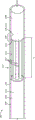
Fig. 3 and 4 illustrate one end of an exemplary multi-core fiber optic cable (MCF) for use with a non-illuminated multi-point laser probe according to certain embodiments of the present invention.
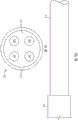
Fig. 5 illustrates one end of an exemplary MCF for use with an illuminated multi-point laser probe according to certain embodiments of the present invention.
Fig. 6 is a partial cross-sectional detail view of a distal portion of an exemplary multi-point laser probe tip according to certain embodiments of the present invention.
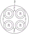
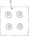
Fig. 7A-7F 2 illustrate various aspects of a multi-point/multi-fiber laser probe as compared to various aspects of an MCF laser probe, in accordance with certain embodiments of the present invention, to highlight various advantages and benefits of a multi-core fiber optic cable laser probe.
Fig. 8 illustrates exemplary operations performed by a surgical laser system according to certain embodiments of the present invention.
Fig. 9 illustrates a distal portion of an exemplary multi-point laser probe operable to generate a multi-point pattern of laser beams according to certain embodiments of the present invention.
Fig. 10 illustrates a distal portion of another exemplary multi-point laser probe in which a lens having a convex end is disposed between the distal end of the MCF and a protective window, according to a specific embodiment of the present invention.
Fig. 11 is a side view of an exposed end of an exemplary multi-point laser probe showing the exposed end of the MCF aligned with a lens, according to certain embodiments of the invention.
Fig. 12 shows that the exposed end of the MCF and the lens are not aligned due to the annular gap formed between the MCF and the inner wall of the cannula.
Fig. 13 shows a ring disposed within an annular void formed around the inner cladding of the MCF at the exposed end of the MCF, in accordance with certain embodiments of the present invention.
Fig. 14 illustrates another exemplary multi-point laser probe cannula including a countersink, according to certain embodiments of the present invention.
Fig. 15 illustrates an exemplary multi-point laser probe in which alignment of the exposed end of the MCF is provided by the reduced inner diameter of the cannula, according to certain embodiments of the present invention.
Figure 16 illustrates the potential risk of damage to the distal end of the MCF during assembly, according to certain embodiments of the present invention.
Figures 17 and 18 illustrate the formation of necked down portions of the cannulas of exemplary multi-point laser probes for maintaining alignment of the distal end of the MCF with the lens, in accordance with certain embodiments of the present invention.
Fig. 19 illustrates exemplary operations for generating a multi-point laser probe according to certain embodiments of the invention.
Detailed Description
In the following description, details are set forth by way of example in order to facilitate an understanding of the disclosed subject matter. However, it will be apparent to those of ordinary skill in the art that the disclosed embodiments are exemplary and not exhaustive of all possible embodiments. Thus, it should be understood that reference to the described examples is not intended to limit the scope of the present disclosure. Any alterations and further modifications in the described devices, instruments, methods, and any further applications of the principles of the disclosure, will fully occur to others skilled in the art to which the disclosure relates. In particular, it is fully contemplated that features, components, and/or steps described for one implementation may be combined with features, components, and/or steps described for other implementations of the present disclosure.
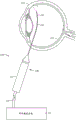
The present disclosure describes illuminated and non-illuminated multi-core laser probes and systems and methods associated therewith. FIG. 1 illustrates an exemplary system 100 for generating a laser beam multi-spot pattern according to some embodiments.
The system 100 includes a surgical laser system 102 that includes one or more laser sources for generating a laser beam that may be used during ophthalmic surgery. For example, the ophthalmic surgical laser system 102 may alternatively generate a surgical treatment beam having a first wavelength (e.g., about 532 nanometers (nm)) and a laser aiming beam having a second wavelength (e.g., about 635 nm). A user, such as a surgeon or a surgical staff member, may control the surgical laser system 102 (e.g., via foot pedal, voice command, etc.) to alternately emit a laser aiming beam and a treatment beam to treat the patient's anatomy, e.g., to perform photocoagulation. In some cases, the surgical laser system 102 may include a port and the laser beam may be emitted through the port in the surgical laser system 102. The surgical laser system 102 may include a laser system port adapter containing optics (not shown) for generating a laser beam multi-spot pattern from a laser beam from a laser source.
The system 100 may deliver multiplexed light beams from the ports to the surgical probe 108 via a multi-core fiber optic cable (MCF) 110. The probe 108 may generate a multi-spot pattern of laser beams to be delivered to the retina 120 of the patient's eye 125. The probe 108 includes a probe body 112 and a probe tip 140 that house and protect the MCF 110. The distal portion 145 of the probe tip 140 also includes a lens (not shown, described in more detail below) that translates the multiplexed beam from the distal end of the MCF 110 onto the retina 120.
A variety of different systems and methods can be employed to create the laser beam multi-spot pattern and multiplex the laser beam multi-spot pattern with the illumination beam. In some cases, the port adapter may contain optical elements operable to generate a multi-point pattern and/or multiplex the light beams. In some implementations, the surgical laser system 102 can also include a female chimney port (not shown), and the port adapter can include a ferrule that serves as a male coupling for the female chimney port. The ferrule may include an opening to allow laser light from the surgical laser system 102 to enter, and one or more optical elements to collimate the laser light received from the laser source. In some examples, the optical element in the ferrule may be a graded index (GRIN) lens having a length and pitch selected such that the optical element collimates the laser light received at the opening of the ferrule at a selected distance adjacent to a Diffractive Optical Element (DOE). In other examples, the optical element may be one of several other types of lenses (e.g., spherical, aspherical, biconvex glass lenses, etc.). The DOE may focus the laser beam multi-spot pattern into an interface plane of the proximal end of the MCF such that each of the laser beams in the multi-spot laser pattern of laser beams propagates along the entire length of a selected core of the plurality of cores contained within the MCF to the distal end of the surgical probe.
In operation, the laser source of the surgical laser system 102 generates a laser beam. Collimation optics in the surgical laser system 102 collimate the laser light directed to a diffractive optical element configured to produce a multi-spot laser pattern of the laser beam. The multi-point laser pattern is then directed to a condenser lens and focusing optics of the surgical laser system 102 to focus the multi-point pattern onto an interface plane at the proximal end of the MCF such that each of the multi-point laser patterns of laser beams propagates along the entire length of a selected core of the plurality of cores contained within the MCF 110. The laser beam multi-spot pattern is transmitted by the MCF 110 to the probe 108 disposed at the distal end of the MCF 110. The laser beam multi-point pattern exits the MCF 110 and is transmitted through a lens at the distal end portion 145 of the probe 108. The laser beam multi-spot pattern exiting the probe 108 may be projected onto the retina 120 of the eye 125.
Fig. 2 illustrates an embodiment of the probe tip 140 of fig. 1 in more detail. As described above, the probe 108 includes a probe body 112 that is shaped and sized for grasping by a user. The probe tip 140 extends from the probe body 112 and includes a cannula 251 and a cannula 250. As shown, cannula 250 is partially received by cannula 251 and extends beyond its distal end. In the illustrated example, the stylet tip 140 includes a straight portion 216 (e.g., a straight portion of the cannula 251 and the cannula 250) and a curved portion 218 (e.g., a curved portion of the cannula 250). In other implementations, the probe tip 140 may have other shapes. For example, in some cases, the probe tip 140 may be entirely straight, include more than one curved portion, be entirely curved, or be shaped in any desired manner.
The probe tip 140 may be formed from one or more materials including, for example, stainless steel, titanium, nitinol, and platinum. In some examples, a first portion (e.g., straight portion 216) of the probe tip 140 may comprise a first material and a second portion (e.g., curved portion 218) of the probe tip 140 may comprise a second material. In some cases, the first material may be different from the second material. For example, in some cases, the first material may comprise stainless steel, such as tubular stainless steel, and the second material may comprise nitinol, such as tubular nitinol. The distal portion 145 of the probe tip 140 can be inserted into the eye to perform a surgical procedure.
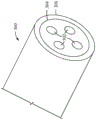
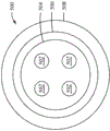
Fig. 3 and 4 illustrate the distal end of an exemplary MCF 300 (e.g., similar to MCF 110) from different angles. MCF 300 includes a plurality of cores 302 disposed in a cladding 304, which may be formed of fused silica. The laser light provided by the laser source discussed above, such as the surgical laser system 102, may be split into multiple beams. Each beam is directed into one of the cores 302 of the MCF 300. Thus, each core 302 directs one of the beams along the length of the MCF 300. In some implementations, these cores 302 may be composed of, for example, germanium-doped silica, and the cladding 304 may be composed of fused silica, such that laser light traveling along the cores 302 is contained within the cores 302 and prevented from escaping from the cores 302 into the cladding 304. For example, the refractive index of one or more cores 302 may be greater than the refractive index of cladding 304.
Although four cores 302 are shown in the illustrated example, the scope of the present disclosure is not limited in this regard. Rather, in other implementations, MCF300 may include fewer cores 302, while other implementations may include more than four cores 302. In some implementations, MCF300 may include two, four, or more inner cores 302, and in some examples, these cores 302 may form a 2x2 array that matches a 2x2 multi-spot pattern generated by a diffractive optical element that may be disposed in a surgical laser system, such as surgical laser system 102. A coating 306 is formed over the cladding 304. In some cases, coating 306 may be a polyimide coating. In other cases, coating 306 may be formed from other materials, such as acrylates. In some implementations, the refractive index of coating 306 may be greater than, less than, or equal to the refractive index of cladding 304.
In some embodiments, each core 302 may have a diameter of about 75+/-2 μm, the cladding 304 may have an outer diameter of about 295+/-5 micrometers (μm), and the coating 506 may have an outer diameter of about 325+/-5 μm. In some embodiments, the centers of two adjacent cores 302 may be about 126+/-5 μm from each other, while the distance between the centers of two cores 302 that are diagonal relative to each other may be about 178+/-5 μm.
In fig. 3 and 4, MCF 300 is a non-illuminated MCF. That is, while each core 302 is adapted to conduct light, such as laser light, the cladding 304 itself is not used to conduct light for general illumination at the treatment site.
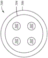
Fig. 5 shows an example of an illuminated MCF, shown as MCF 500.MCF 500 includes a plurality of cores 502 disposed in an inner cladding 504, which may be formed of fused silica. These cores 502 function similarly to the cores 302 described above. Although four cores 502 are shown in the illustrated example, the scope of the present disclosure is not limited in this regard. Rather, in other implementations, MCF 500 may include fewer cores 502, while other implementations may include more than four cores 502. In some implementations, MCF 500 may include two, four, or more inner cores 502, and in some examples, these cores 502 may form a 2x2 array that matches a 2x2 multi-spot pattern generated by a diffractive optical element that may be disposed in a surgical laser system, such as surgical laser system 102. An outer cladding 506 is formed over the inner cladding 504. MCF 500 further includes a coating 508 formed on outer cladding 506. Coating 508 may refer to an outer jacket. In some cases, the outer cladding 504 and the coating 508 may be formed from a polymeric material.
Illumination MCF is one that transmits light for general illumination (as opposed to a targeted laser for treatment) through the MCF's cladding to provide general illumination at the treatment site. Thus, the inner cladding 504 may be used to transmit light therealong to provide general illumination at the treatment site (as opposed to laser light used for treatment). In illumination MCF500, the refractive index of outer cladding 506 may be less than the refractive index of inner cladding 504. The outer cladding 506 (which may be a hard silica cladding) may be formed of a polymeric material that may be unstable at high temperatures. Thus, a portion of the outer cladding 506 may be peeled or otherwise removed from the MCF500 near the interface with the lens (e.g., about 0.5 to 5 mm), as described below, to improve the power handling capability of the probe containing the MCF 500. In certain embodiments, the coating 508 is removed from the distal end of the MCF500 to a length of about 50 millimeters (mm). This length may correspond to the length of a cannula (e.g., cannula 250). The coating 508 may be removed to allow the MCF500 to fit into the cannula because the outer diameter of the MCF500 may be greater than the inner diameter of the cannula when the coating 508 is thereon.
In some embodiments, each core 502 may have a diameter of about 75+/-2 μm, the inner cladding 504 may have an outer diameter of 295+/-5 μm, the outer cladding 506 may have an outer diameter of 325+/-5 μm, and the coating 508 may have an outer diameter of 425+/-30 μm. In some embodiments, the centers of two adjacent cores 502 may be about 126+/-5 μm from each other, while the distance between the centers of two cores 502 that are diagonal relative to each other may be about 178+/-5 μm.
Fig. 6 is a partial cross-sectional detail view of the distal portion 145 of the probe tip 140 shown in fig. 2. Note that the distal portion 145 of the probe tip 140 may also be the distal portion of the cannula 250. As described above, the probe tip 140 (including the cannula 250) may be formed of one or more materials, such as, for example, stainless steel, titanium, nitinol, or platinum. The MCF 600 (which may be an illuminating MCF (e.g., the MCF 500 described above) or a non-illuminating MCF (e.g., the MCF 300 described above) extends through the cannula 250 of the probe tip 140 and includes a plurality of cores 602 that may function similarly to the cores 302 and 502 of fig. 3 and 5, respectively, in the illustrated example, the MCF 600 includes four cores 602, but as explained above, the MCF 600 may include fewer or additional cores, e.g., to provide a desired number of laser beams.
The distal portion 604 of the MCF 600 is disposed at the distal portion 145 of the probe tip 140 and is described in more detail below. Distal portion 604 terminates at an interface 606 with lens 608. The interface 606 may be configured to translate the geometry of the multiplexed multi-point laser pattern from the distal end of the MCF 600, through the lens 608, and onto a target surface, such as tissue at a treatment site.
A portion of the outer cladding is removed (e.g., by peeling) at the distal end 616 of the outer cladding 610 of the MCF 600, thereby exposing the cladding 612. Thus, at interface 606, cladding 612 of MCF 600 is exposed. In some cases, the outer cladding 610 may be removed or omitted for a length L measured from the distal end 616 of the MCF 600 to mitigate or eliminate thermal problems (e.g., temperature increase at the interface of the MCF 600 and the lens 608), thereby improving performance of the laser probe. For example, removing the outer cladding 610 at the interface 606 between the MCF 600 and the lens 608 improves the power handling characteristics of the probe 108. That is, by removing the outer cladding 610, the power level of the laser light passing through the probe 108 may be greater than the power level of the laser light that could pass through the probe 108 without removing the outer cladding 610 from the MCF 600 at the interface 606. Thus, with the outer cladding 610 removed as described, higher thermal loading of the probe 108, particularly at the interface 606, is possible.
In some cases, the length L may be in the range of 0.5mm to 5.0 mm. In some cases, the length L may be in the range of 1.0mm to 3.0mm and may be any length therein. In particular, in some cases, the length L may be 1.0mm, 1.5mm, 2.0mm, 2.5mm, or 3.0mm. In addition, the length L may be any length between these values. At interface 606, a distal face 618 of MCF 600 may abut a proximal face 614 of lens 608. In other cases, the distal face 618 of the MCF 600 may be offset from the proximal face 614 of the lens 608.
In some implementations, a distal face 618 formed at the distal end 616 of the MCF600 may abut the proximal face 614 of the lens 608 at a positive pressure. In other implementations, the distal face 618 of the MCF600 may be separated from the proximal face 614 of the lens 608 by an air gap. In still other implementations, one or more optically transmissive elements or materials may be located at the interface 606 between the MCF600 and the lens 608. In some implementations, the lens 608 may be a GRIN lens, a spherical lens, or an aspherical lens. In still other implementations, the lens 608 may be a set of lenses formed of an optically transparent material.
Although MCF 600 is described in the context of a non-illumination type, the scope of the present disclosure is not limited in this regard. Rather, the concepts described herein are equally applicable to illuminating MCFs. Thus, MCF 600 may be an illumination MCF, similar to MCF 500 of fig. 5.
Fig. 7A-7D, fig. 7E 1-7E 2, and fig. 7F 1-7F 2 compare a multi-spot/multi-fiber laser probe as described herein with an embodiment of an MCF laser probe to highlight a number of different advantages and benefits of an MCF laser probe. Fig. 7A-7B illustrate a plurality of optical fibers 710 that may be used in a multi-point/multi-fiber laser probe (not shown), where each optical fiber 710 is configured to conduct a single laser beam. More specifically, fig. 7A illustrates a front view of an optical fiber 710 housed in a multilumen tube 760 (e.g., a micro-spacer). As shown, the multilumen tubing 760 includes four tunnel-shaped passages or holes 716, each of which accommodates an optical fiber 710. An adhesive 715 is used to bond each optical fiber 710 to its corresponding hole 716. Fig. 7B shows a side view of an optical fiber 710 extending from a cannula 750. Note that fig. 7B does not show the multilumen tube of fig. 7A.
In general, during the fabrication of a multi-point/multi-fiber laser probe, it is difficult to precisely control a plurality of individual optical fibers 710. The multi-point/multi-fiber laser probe design may require precise alignment of multiple individual fibers 710 within the Inner Diameter (ID) of the ferrule in order to accommodate the multiple laser beams with the required high coupling efficiency. For example, using polyimide tubing to manage multiple individual optical fibers 710 and individually stripping each optical fiber 710 can be time consuming. After stripping, the plurality of optical fibers 710 are inserted into corresponding holes in the multilumen tubing 760, which can be difficult and slow. In addition, the fibers 710 are split individually, retracted into the polyimide and multilumen tubing 760, brought flush by stops, and bonded together by UV during adhesion. This assembly is then subjected to a second thermal cure to improve the adhesive stability at high temperatures. Such manufacturing processes associated with multi-point/multi-fiber designs are complex and slow. The adhesive 715 used between each optical fiber and its corresponding hole or housing 716 in the multilumen tubing 760 may also be susceptible to thermal damage and may cause probe failure.
Fig. 7C and 7D show MCF 720, similar to MCF 300, MCF 500, and MCF 600 shown in fig. 4-6, as compared to fig. 7A and 7B. More specifically, fig. 7C illustrates a front view of MCF 720 including a plurality of cores 702 embedded in cladding 704, which is coated with coating 724. Fig. 7D shows a side view of MCF 720 extending from cannula 752. As shown, MCF 720 is a single optical fiber having multiple cores 702, each of which transmits a laser beam, as opposed to multiple optical fibers 710 of a multi-point/multi-fiber laser probe.
Laser probes incorporating MCFs, such as MCF 720, do not require the use of an adhesive between cores 702 because cores 702 are embedded in cladding 704 and contained within a single optical fiber. Thus, a laser probe containing MCF can have significantly improved power handling capabilities. Furthermore, the assembly of the MCF laser probe is relatively simple, since only a single optical fiber needs to be aligned and manipulated during manufacturing. Accordingly, polyimide tubing and multi-lumen tubing are not required to manage the multiple individual fibers during assembly, and the time spent stripping a single MCF 720 is significantly less than the time spent stripping multiple individual fibers 710 of a multi-point/multi-fiber probe.
In addition, the use of MCF in a laser probe may allow for tight control of the direction of the propagating beam. More specifically, the use of MCF ensures that the beam propagated by the laser probe is tightly controlled and does not point to the inner surface of the cannula. Fig. 7E 1-7E 2 and fig. 7F 1-7F 2 illustrate a comparison between laser beam patterns associated with a plurality of optical fibers of a multi-point/multi-fiber laser probe and a laser beam pattern associated with a core of an MCF.
Fig. 7E1 depicts a fiber pattern within a multilumen tubing 760 at the distal end of a fiber optic assembly comprising a plurality of optical fibers 710. Fig. 7E2 shows a laser beam pattern 770 including laser beam spots 772 corresponding to the fiber pattern of fig. 7E 1. As shown, some of the optical fibers 710 (e.g., upper right core and lower right core) are not centered within the passageway 716 of the multilumen tubing 760, which results in that the bundles that these optical fibers 710 propagate may be skewed outward, as shown in fig. 7E 2. In some cases, some of the optical fibers 710 may not be centered within their corresponding passages 716 due to loose tolerances between the outer diameter of the optical fibers 710 and the inner diameter of the passages 716 of the multilumen tubing 760 such that the optical fibers 710 instead are directed toward the inner surface of the cannula (not shown). Thus, the bundle of optical fibers 710 propagating is also directed toward the inner surface of the cannula, rather than in a straight direction toward the patient's eye. This allows the beams to escape the lens of the laser probe, such as lens 608, and be absorbed by the inner surface of the cannula, which may cause the cannula to overheat. Furthermore, the optical fibers 710 are not centered within their corresponding passages 716 resulting in undesirable uniformity among the corresponding four beam spots.
Fig. 7F1 to 7F2 show the fiber pattern and the bundle pattern associated with the MCF, respectively, as compared to fig. 7E1 to 7E 2. Fig. 7F1 shows the cores 702 of the MCF pointing in a straight direction and not being skewed outward. This is because the cores 702 are closely embedded together in the cladding. Thus, the core 702 is able to propagate spots 782 (shown in the beam pattern 782 of fig. 7F 2) that are also directed in a straight direction and not toward the inner surface of a cannula (not shown) in which the MCF is housed. In this way, the use of MCF improves control of the laser beam pattern of the laser probe (e.g., desired uniformity among the four spots) and increases power handling by preventing overheating of the cannula due to the beam pointing towards the inner surface of the cannula.
Thus, the disclosed MCF laser probe design can simplify manufacturing by eliminating complex and expensive manufacturing requirements, improve power handling by eliminating adhesive failure during bonding of distal ends of multiple optical fibers or eliminating the introduction of contaminants into the distal fiber assembly of a multi-fiber probe, increase coupling efficiency by employing precisely aligned MCFs and avoiding difficulties associated with aligning individual optical fibers with multiple input laser beams in a multi-fiber assembly, and improve control of laser beam patterns (which further improves power handling). These and other advantages will be apparent to those skilled in the art in view of this disclosure.
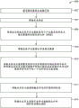
Fig. 8 illustrates an exemplary flowchart 800 showing steps in a method for applying a multi-spot laser beam pattern, according to certain embodiments of the invention. In certain embodiments, operation 800 is performed by a system, such as surgical laser system 102 of fig. 1, coupled to an MCF laser probe, such as MCF laser probe 108 of fig. 1.
At block 802, the system generates a laser beam by a laser source. As described above, the laser source may be part of or coupled with the surgical laser system 102.
At block 804, the system collimates the laser beam. A collimated laser beam refers to a laser beam having parallel rays.
At block 806, the system directs the collimated laser beam to a Diffractive Optical Element (DOE) configured to generate a multi-point laser pattern of the laser beam. As one of ordinary skill in the art recognizes, the DOE is used to shape and split the laser beam.
At block 808, the system directs the laser beam multi-point pattern to a condenser lens.
At block 810, the system focuses the laser beam multi-spot pattern into an interface plane of a proximal end of the MCF such that each of the multi-spot laser patterns of the laser beam is transmitted into and propagates along one of a plurality of cores of the MCF surrounded by the cladding layer and the cladding layer is surrounded by the cladding layer, each of the plurality of cores having a refractive index greater than a refractive index of the cladding layer, and a portion of the cladding layer is omitted from a length of a distal end of the MCF.
For example, the surgical laser system 102 focuses the laser beam multi-spot pattern into an interface plane of a proximal end of an MCF (e.g., MCF 110, MCF 300, MCF 500, MCF 600, etc.) such that each of the laser beams in the multi-spot laser pattern of laser beams is transmitted into and along one of a plurality of cores (e.g., cores 302, 502, 602, etc.) of the MCF surrounded by a cladding (e.g., cladding 304, 504, 506, 612) and the cladding is surrounded by a coating (e.g., 306, 508, etc.), each of the plurality of cores having a refractive index greater than that of the cladding, and a portion of the coating is omitted from a length of a distal end of the MCF (e.g., length L of fig. 6).
At block 812, the system transmits a laser beam multi-point pattern to the far end of the MCF. For example, the system transmits a laser beam multi-point pattern to the distal end of the MCF (e.g., distal end 616).
At block 814, the system directs the laser beam multi-point pattern through a lens (e.g., lens 608) to a distal tip (e.g., distal tip 620) of a surgical probe (e.g., probe 108).
Fig. 9 illustrates a distal portion of another exemplary probe 901 operable to generate a laser beam multi-spot pattern. The illustrated exemplary probe 901 includes an illuminating MCF 900, which may be similar to the MCF 500 described above. Thus, probe 901 is operable to emit both general illumination for illuminating the surgical field, as well as a plurality of laser beams for treating a treatment site, such as the retina. Probe 901 may be similar in many respects to probe 108. As shown, the probe 901 includes a cannula 902. The cannula 902 includes an inner surface 936 defining an interior passage 942. The MCF 900 extends through at least a portion of the cannula 902 up to a first interface 906 with the lens 908. MCF 900 may abut lens 908 or a void, such as an air-filled void, may be disposed between distal end 916 of MCF 900 and proximal end 914 of lens 908. In some cases, the distal end 916 of the MCF 900 may abut the proximal end 914 of the lens 908 at a positive pressure. In some cases, the lens 908 may be formed of fused silica, borosilicate, or sapphire. In some cases, lens 908 may be a spherical lens. Lens 908 may be a GRIN lens, such as a single element cylindrical GRIN rod lens, operable to receive one or more laser beams from the distal end of MCF 900 and relay the received laser beams toward the distal tip 920 of probe 901.
The probe 901 further includes a protective window 918 extending from a second interface 922 with the lens 908. As shown in fig. 9, the protection window 918 abuts the lens 908. In other implementations, there may be a void, such as an air-filled void, between the protective window 918 and the lens 908. In the illustrated example, the protective window 918 extends distally beyond the distal end 924 of the cannula 902, and the distal end 926 of the protective window 918 defines the distal tip 920 of the probe 901. In other implementations, the distal end 926 of the protective window 918 may be aligned with the distal end of the distal end 924 of the cannula 902 such that the distal end 924 of the cannula 902 and the distal end 926 of the protective window 918 are substantially flush. Those of ordinary skill in the art will recognize that the relative position of the end surface of the distal end 924 of the cannula 902 and the end surface of the distal end 926 of the protective window 918 may vary slightly due to manufacturing tolerances.
The protection window 918 may be formed of an optically stable and high temperature resistant material. In some cases, the protection window 918 may be formed of sapphire or quartz. In some cases, the protective window 918 may have a planar proximal surface, as shown in fig. 9. In other cases, the protective window 918 may have a convex proximal surface 928. Fig. 10 shows an example of such a lens.
In fig. 10, lens 1008 has a convex proximal end and a distal end. Although the lens 1008 is elongated in the longitudinal direction, in other examples it may instead be a spherical or ball lens. In some implementations, a lens having a flat proximal end and/or a flat distal end, such as lens 908 shown in fig. 9, may be used in conjunction with a protective window 1018 having a convex proximal end, similar to that shown in fig. 10. In still other implementations, the probe may include a lens having a convex proximal end and/or a convex distal end, such as a spherical lens or the lens shown in fig. 9, to incorporate a protective window having a flat proximal end, such as protective window 918 shown in fig. 9.
Referring back to fig. 9, the mcf 900 includes an outer cladding 930, which may be similar to the outer cladding 506 shown in fig. 5. The outer cladding 930 is peeled away from the inner cladding 932, e.g., by a length L measured from the distal end 916 of the MCF 900 and extending proximally, thereby exposing the underlying inner cladding 932.
In some cases, the length L may be in the range of 0.5mm to 5.0 mm. In some cases, the length L may be in the range of 1.0mm to 3.0mm and may be any length therein. In particular, in some cases, the length L may be 1.0mm, 1.5mm, 2.0mm, 2.5mm, or 3.0mm. In addition, the length L may be any length between these values. As explained above, removing a portion of the outer cladding may improve the thermal handling characteristics of the probe, which may increase the power level of the laser energy transmitted through the probe. A portion of a core 933 is shown extending through the inner cladding 932.
However, with a portion of the outer cladding 930 removed, an annular void 934 exists between the inner cladding 932 and the inner surface 936 of the cannula 902. The annular void 934 introduces a risk of misalignment between the MCF 900 and the lens 908 (i.e., the MCF 900 may be eccentric relative to the lens 908). Fig. 11 is a side view of the exposed end 938 of the probe 901, wherein the exposed end 938 of the MCF 900 is aligned with the lens 908. The exposed end 938 of the MCF 900 is the portion of the MCF 900 from which the outer cladding 930 is removed.
However, fig. 12 shows the exposed end 938 of the MCF 900 and the lens 908 not aligned due to the annular void 934. As shown in fig. 12, the exposed end 938 of the MCF 900 is not concentric with the lens 908. With the exposed end 938 of the MCF 900 misaligned with the lens 908, the resulting laser spot and illumination beam pattern is no longer concentric with the cannula 902. This misalignment between the MCF 900 and the lens 908 may also cause a portion of the light to be transmitted for general illumination and to impinge on the inner wall 936 of the cannula 902 through the inner cladding 932. This reduces the illumination efficiency of the probe 901 and results in an undesirable illumination pattern.
In certain embodiments, to maintain alignment between the MCF 900 and the lens 908, a ring of thermally stable material may be disposed in the annular void 934 to maintain concentricity of the MCF 900 with the interior passageway of the cannula and the lens. In certain embodiments, the material may include, for example, polyimide, metal, stainless steel, nickel, silver, copper, brass, and the like. While polyimide and metal are possible materials from which the ring may be made, other materials may be used. Fig. 13 illustrates an example of a ring for maintaining alignment between the MCF 900 and the lens 908.
Fig. 13 shows a ring 940 disposed within an annular void 934 formed around an inner cladding 932 at an exposed end 938 of the MCF 900. The ring 940 maintains concentricity of the MCF 900 with the lens 908, for example, by limiting lateral movement of the exposed end 938 of the MCF 900. In some cases, the inner diameter of the ring 940 corresponds to the outer diameter of the exposed end 938 of the MCF 900. In some cases, the outer diameter of the ring 940 corresponds to the inner diameter of the inner passageway 942. The ring 940 may span the entire length L of the exposed end 938 or less than the entire length L.
Fig. 14 illustrates another exemplary implementation for maintaining alignment of the MCF 900 with the lens 900. In the example shown in fig. 14, cannula 1402 includes an internal passageway 942 having a first inner diameter 1444 that more closely conforms to the outer diameter of MCF 900. Cannula 1402 also includes a counterbore 946 having a second inner diameter 1448 that is greater than first inner diameter 1444. Counterbore 946 is provided to accommodate lens 908 and protective window 918 (if included) within cannula 1402 because the lateral cross-sectional size of these components is larger than the lateral cross-sectional size of MCF 900. Thus, along the exposed end 938, a passageway 942 having a reduced cross-sectional size compared to the counterbore 946 is able to maintain alignment of the exposed end 938 of the MCF 900 with the lens 908 to a greater extent than if the inner diameter 1444 of the passageway 942 were the size of the inner diameter 1448 of the counterbore 946. Thereby, the alignment between the MCF 900 and the lens 908 is improved. In some cases, a counterbore 946 extends proximally from the distal end of cannula 1402.
Fig. 15 shows the following examples: the reduced inner diameter 1550 of the cannula 1502 provides alignment of the exposed end 938 of the MCF 900. The necked down portion 1552 of the cannula 1502 (which may be the result of crimping) provides a reduced diameter 1550. The reduced inner diameter 1550 may be made to correspond to the outer diameter of the exposed end 938 of the MCF 900. The reduced inner diameter 1550 maintains alignment of the exposed end 938 with the lens 908, thereby achieving improved general illumination performance and alignment of the laser spot pattern with the longitudinal axis of the cannula 1502.
Fig. 16 illustrates the potential risk of damage to the MCF 900 during assembly of the multi-point laser probe in the context shown in fig. 15. If the necked portion 1652 of the cannula 1602 (such as that created by a crimp applied to the cannula 1602) is formed prior to introduction of the MCF 900 into the necked portion 1652, there is a risk of damage to the distal end 1654 when attempting to insert the distal end 1654 of the MCF 900 (particularly the edge 1656 of the distal end 1654) through the necked portion 1652. Misalignment of the distal end 1654 with the necked portion 1652 during assembly may create forces that may gouge and damage the distal end 1654 of the MCF 900. Even small loads applied to the distal end 1654, and particularly to the edge 1656 thereof, may cause damage, such as gouging of the distal end 1654 and the edge 1656, which may lead to performance impairment, either in poor general illumination or in inaccurate or distorted laser spot patterns or both. Such damage may render the resulting laser probe unusable. Thus, a necked-down portion may be formed in the cannula after the MCF is introduced into the cannula, as shown in fig. 17 and 18.
Fig. 17 and 18 illustrate the distal end 1654 of the MCF 800 abutting the lens 908 at the first interface 906. However, as explained above, a gap may be disposed between the distal end 1654 of the MCF 800 and the lens 908. In some implementations, one or both of the lens 908 and window 918 may be installed in the cannula 1702 prior to assembly of the MCF 900. In some implementations, MCF 900 may be installed before one or both of lens 908 and window 918.
With the MCF 900 positioned at a desired location within the cannula 1702, a necked-down portion 1752 may be formed in the cannula 1702, such as by crimping. The necked-down portion 1752 maintains the exposed end 938 of the MCF 900 concentric with the lens 908. Thereby, the risk of damaging the distal end 1654 of the MCF 900 by the necked-down portion 1752 is eliminated.
In some cases, necked-down portion 1752 is a reduced annular body that completely surrounds exposed end 938 of MCF 900. Thus, the necked down portion 1752 defines a reduced diameter 1858 of the inner passageway 942 that conforms to the outer diameter of the exposed end 938. In some cases, the reduced diameter 1858 of the necked portion 1752 is equal to or slightly greater than the outer diameter of the exposed end 938. As an example, a 5 μm annular void may be formed between the inner surface of the cannula 1702 at the necked down portion 1752 and the outer surface of the exposed end 938. In some embodiments, the exposed end 938 may contact the inner surface of the necked-down portion 1752 at one or more locations.
In certain embodiments, the necked-down portion 1752 may form diametrically opposed protrusions at one or more locations around the circumference of the cannula 1702, thereby centering the exposed end 938 of the MCF 900 with the lens 908. For example, in some cases, necked portion 1752 may include two sets of diametrically opposed projections that are offset from each other by 90 °. In certain other implementations, three or more non-diametrically opposed projections may be formed in the cannula to center the exposed end 938 of the MCF 900. In some cases, the protrusions may be formed along a common circumference of the cannula 1702. In other implementations, one or more protrusions may be longitudinally offset relative to one or more other protrusions.
Additionally, while the MCF 900 is described as an illuminated MCF, in some implementations, the MCF 900 may be a non-illuminated MCF and still be within the scope of the present disclosure.
Fig. 19 illustrates an exemplary flowchart 1900 showing steps in a method for generating a multi-point laser probe, in accordance with certain embodiments of the invention.
At block 1902, a probe tip is provided that includes a cannula configured to be inserted into an eye. For example, a technician or machine may provide a probe tip 901 having a cannula 1702, as shown in fig. 18.
At block 1904, a lens is inserted into the cannula. For example, a lens 908 is inserted into the cannula 1702.
At block 1906, the MCF is inserted into the cannula, proximal to the lens. For example, the MCF 900 is inserted into the cannula 1702 adjacent to the lens 908, the MCF 900 including a plurality of cores 933. As shown, the MCF 900 includes a cladding 932, shown at an exposed end 938 of the MCF 900.
At block 1908, a necked portion is formed in the cannula, the necked portion forming a reduced cross-sectional size to maintain the exposed portion of the MCF centered within the cannula. For example, a necked down portion 1752 is formed in the cannula 1702.
Although several of the figures described herein illustrate probes having protection windows, it should be understood that the protection windows may be omitted. It is further within the scope of the present disclosure that the ends of the lens and/or the protective window may be shaped other than flat. For example, one or more of the distal and proximal ends of the lens and/or protective window may have a convex shape, as described herein.
The above-disclosed subject matter is to be considered illustrative, and not restrictive, and the appended claims are intended to cover all such modifications, enhancements, and other embodiments, which fall within the true spirit and scope of the present disclosure. Thus, to the maximum extent allowed by law, the scope of the present disclosure is to be determined by the broadest permissible interpretation of the following claims and their equivalents, and shall not be restricted or limited by the foregoing detailed description.
Claims (18)
1. A multi-point laser probe system comprising:
a laser source;
a diffractive optical element in optical communication with the laser source;
a probe body shaped and sized for grasping by a user;
a probe tip comprising a cannula configured to be inserted into an eye;
a graded index GRIN lens disposed in the cannula at a distal portion thereof;
a multicore fiber MCF extending at least partially through the cannula, the MCF comprising:
a plurality of cores having uniform core diameters and spacing;
a cladding surrounding the plurality of cores, one or more of the plurality of cores having a refractive index greater than a refractive index of the cladding;
a coating surrounding the cladding;
a proximal end in optical communication with the diffractive optical element; and
a distal end disposed at an interface with the GRIN lens, a portion of the coating omitted from a length of the distal end of the MCF, wherein the omitted length of the coating is sufficient to mitigate temperature increases at the interface between the multicore fiber and the GRIN lens, and
wherein the GRIN lens is configured to translate the multi-point laser beam onto a target surface;
Wherein the diffractive optical element is configured to separate laser light from a laser light source to produce a laser beam multi-spot pattern into an interface plane of the proximal end of the multi-core optical fiber to simultaneously transmit the multi-spot laser beam along the plurality of cores of the multi-core optical fiber, wherein the multi-spot pattern is configured to align with uniform diameters and spacing of the plurality of cores.
2. The multi-point laser probe system of claim 1, wherein the plurality of cores form a 2 x 2 array configured to match a 2 x 2 multi-point pattern from a Diffractive Optical Element (DOE).
3. The multi-point laser probe system of claim 2, wherein a distal end of the MCF abuts the GRIN lens at the interface at positive pressure.
4. The multi-point laser probe system of claim 2, wherein the distal end of the MCF is separated from the GRIN lens by an air gap.
5. The multi-point laser probe system of claim 1, wherein the length of the portion of the coating removed from the MCF is in the range of 0.5mm (millimeters) to 5.0mm extending proximally from the distal end of the MCF.
6. The multi-point laser probe system according to claim 5, wherein the length of the portion of the coating that is removed from the MCF is in the range of 0.1mm to 3.0mm extending proximally from the distal end of the MCF.
7. The multi-point laser probe system of claim 1, further comprising:
a second cladding surrounding the cladding, the second cladding comprising a polymer, wherein the coating surrounds the second cladding, the coating comprising a polymer.
8. The multi-point laser probe system of claim 1, further comprising a ring that is not a coating or cladding surrounding the multi-core fiber at a length within the ferrule where the coating has been omitted to maintain concentricity of the multi-core fiber by limiting lateral movement of a portion of the multi-core fiber having the length of the omitted coating.
9. A multi-point laser probe system comprising:
a laser source;
a diffractive optical element in optical communication with the laser source;
a multi-core optical fiber MCF comprising a plurality of cores surrounded by a cladding and a coating surrounding the cladding, wherein the plurality of cores have a uniform core diameter and spacing, and wherein one or more of the plurality of cores has a refractive index greater than that of the cladding, wherein a proximal end of the multi-core optical fiber is in optical communication with the diffractive optical element, and wherein a distal end of the multi-core optical fiber is disposed at an interface with a graded-index GRIN lens, a portion of the coating omitted from a length of the distal end of the MCF, wherein the omitted length of the coating is sufficient to mitigate temperature increases at the interface between the multi-core optical fiber and the GRIN lens;
A probe comprising a probe tip coupled to a distal end of the MCF; and
the GRIN lens at a distal end of the probe tip, wherein:
the GRIN lens is configured to translate a multi-point laser beam onto a target surface; and
the distal end of the MCF terminates at an interface with the GRIN lens;
wherein the diffractive optical element is configured to separate laser light from a laser light source to produce a laser beam multi-spot pattern into an interface plane of the proximal end of the multi-core optical fiber to simultaneously transmit the multi-spot laser beam along the plurality of cores of the multi-core optical fiber, wherein the multi-spot pattern is configured to align with uniform diameters and spacing of the plurality of cores.
10. The multi-point laser probe system of claim 9, wherein:
the coating comprises a polyimide coating;
the plurality of cores comprise germanium-doped silica; and
the cladding comprises fused silica.
11. The multi-point laser probe system according to claim 10, wherein the length is in the range of 1.0mm to 3.0 mm.
12. The multi-point laser probe system of claim 9, wherein the plurality of cores form a 2 x 2 array configured to match a 2 x 2 multi-point pattern from a Diffractive Optical Element (DOE).
13. The multi-point laser probe system of claim 9, wherein the probe tip comprises a cannula configured to be inserted into an eye, and wherein the GRIN lens and the distal end of the MCF are disposed in the cannula.
14. The multi-point laser probe system of claim 9, wherein a distal end of the MCF abuts the GRIN lens at positive pressure.
15. The multi-point laser probe system of claim 9, wherein the distal end of the MCF is separated from the GRIN lens by a gap.
16. The multi-point laser probe system of claim 9, wherein the probe tip comprises a cannula configured to be inserted into an eye,
the distal end of the MCF and the GRIN lens are disposed in the cannula,
the omitted portion of the coating at the MCF has a length sufficient to improve the power handling characteristics of the multi-point laser probe, and
wherein the plurality of cores form a 2 x 2 array configured to match a 2 x 2 multi-spot pattern from a Diffractive Optical Element (DOE).
17. The multi-point laser probe system of claim 9, wherein the distal end of the MCF is separated from the GRIN lens by an air gap.
18. The multi-point laser probe system of claim 9, further comprising:
A second cladding surrounding the cladding, the second cladding comprising a polymer, wherein the coating surrounds the second cladding, the coating comprising a polymer.
Priority Applications (1)
| Application Number | Priority Date | Filing Date | Title |
|---|---|---|---|
| CN202310508994.7A CN116270010A (en) | 2017-12-12 | 2018-12-12 | Multi-core optical fiber for multi-point laser probe |
Applications Claiming Priority (9)
| Application Number | Priority Date | Filing Date | Title |
|---|---|---|---|
| US201762597550P | 2017-12-12 | 2017-12-12 | |
| US62/597,550 | 2017-12-12 | ||
| US201762598653P | 2017-12-14 | 2017-12-14 | |
| US62/598,653 | 2017-12-14 | ||
| US201862622299P | 2018-01-26 | 2018-01-26 | |
| US62/622,299 | 2018-01-26 | ||
| US201862630865P | 2018-02-15 | 2018-02-15 | |
| US62/630,865 | 2018-02-15 | ||
| PCT/IB2018/059979 WO2019116285A1 (en) | 2017-12-12 | 2018-12-12 | Multi-core fiber for a multi-spot laser probe |
Related Child Applications (1)
| Application Number | Title | Priority Date | Filing Date |
|---|---|---|---|
| CN202310508994.7A Division CN116270010A (en) | 2017-12-12 | 2018-12-12 | Multi-core optical fiber for multi-point laser probe |
Publications (2)
| Publication Number | Publication Date |
|---|---|
| CN111511305A CN111511305A (en) | 2020-08-07 |
| CN111511305B true CN111511305B (en) | 2023-05-12 |
Family
ID=65041807
Family Applications (7)
| Application Number | Title | Priority Date | Filing Date |
|---|---|---|---|
| CN201880080560.9A Active CN111479534B (en) | 2017-12-12 | 2018-12-12 | Thermally robust laser probe assembly |
| CN201880080456.XA Active CN111511305B (en) | 2017-12-12 | 2018-12-12 | Multi-core optical fiber for multi-point laser probe |
| CN201880080457.4A Active CN111479533B (en) | 2017-12-12 | 2018-12-12 | Multi-input coupled illumination type multi-point laser probe |
| CN201880080561.3A Active CN111479535B (en) | 2017-12-12 | 2018-12-12 | Multi-core optical fiber for multi-point laser probe |
| CN201880080453.6A Active CN111491594B (en) | 2017-12-12 | 2018-12-12 | Thermally robust laser probe assembly |
| CN202310226338.8A Pending CN116211584A (en) | 2017-12-12 | 2018-12-12 | Multi-input coupled illumination type multi-point laser probe |
| CN202310508994.7A Pending CN116270010A (en) | 2017-12-12 | 2018-12-12 | Multi-core optical fiber for multi-point laser probe |
Family Applications Before (1)
| Application Number | Title | Priority Date | Filing Date |
|---|---|---|---|
| CN201880080560.9A Active CN111479534B (en) | 2017-12-12 | 2018-12-12 | Thermally robust laser probe assembly |
Family Applications After (5)
| Application Number | Title | Priority Date | Filing Date |
|---|---|---|---|
| CN201880080457.4A Active CN111479533B (en) | 2017-12-12 | 2018-12-12 | Multi-input coupled illumination type multi-point laser probe |
| CN201880080561.3A Active CN111479535B (en) | 2017-12-12 | 2018-12-12 | Multi-core optical fiber for multi-point laser probe |
| CN201880080453.6A Active CN111491594B (en) | 2017-12-12 | 2018-12-12 | Thermally robust laser probe assembly |
| CN202310226338.8A Pending CN116211584A (en) | 2017-12-12 | 2018-12-12 | Multi-input coupled illumination type multi-point laser probe |
| CN202310508994.7A Pending CN116270010A (en) | 2017-12-12 | 2018-12-12 | Multi-core optical fiber for multi-point laser probe |
Country Status (11)
| Country | Link |
|---|---|
| US (8) | US11160686B2 (en) |
| EP (6) | EP3723680B1 (en) |
| JP (7) | JP2021505302A (en) |
| KR (2) | KR20200098549A (en) |
| CN (7) | CN111479534B (en) |
| AU (5) | AU2018385649B2 (en) |
| BR (2) | BR112020011655A2 (en) |
| CA (5) | CA3084739A1 (en) |
| ES (1) | ES2946276T3 (en) |
| RU (2) | RU2770121C2 (en) |
| WO (5) | WO2019116284A1 (en) |
Families Citing this family (26)
| Publication number | Priority date | Publication date | Assignee | Title |
|---|---|---|---|---|
| US10918522B2 (en) | 2017-06-08 | 2021-02-16 | Alcon Inc. | Photodisruption-based vitrectomy system |
| EP3678617A1 (en) | 2017-11-14 | 2020-07-15 | Alcon Inc. | Multi-spot laser probe with illumination features |
| CN111479534B (en) * | 2017-12-12 | 2023-02-17 | 爱尔康公司 | Thermally robust laser probe assembly |
| JP2021505314A (en) | 2017-12-12 | 2021-02-18 | アルコン インコーポレイティド | Multi-input coupled illuminated multi-spot laser probe |
| US11213426B2 (en) | 2017-12-12 | 2022-01-04 | Alcon Inc. | Thermally robust multi-spot laser probe |
| WO2019116283A1 (en) | 2017-12-12 | 2019-06-20 | Novartis Ag | Surgical probe with shape-memory material |
| US10758415B2 (en) * | 2018-01-17 | 2020-09-01 | Topcon Medical Systems, Inc. | Method and apparatus for using multi-clad fiber for spot size selection |
| US11389241B2 (en) | 2019-01-15 | 2022-07-19 | Boston Scientific Scimed, Inc. | Alignment method and tools |
| CN113924515A (en) | 2019-06-03 | 2022-01-11 | 爱尔康公司 | Alignment of multi-wavelength laser beams with cores of multi-core optical fibers |
| US11931297B2 (en) | 2019-06-14 | 2024-03-19 | Alcon Inc. | Glare reduction endoilluminators |
| WO2020256898A1 (en) | 2019-06-19 | 2020-12-24 | Boston Scientific Scimed, Inc. | Balloon surface photoacoustic pressure wave generation to disrupt vascular lesions |
| US11717139B2 (en) | 2019-06-19 | 2023-08-08 | Bolt Medical, Inc. | Plasma creation via nonaqueous optical breakdown of laser pulse energy for breakup of vascular calcium |
| US11660427B2 (en) | 2019-06-24 | 2023-05-30 | Boston Scientific Scimed, Inc. | Superheating system for inertial impulse generation to disrupt vascular lesions |
| US20200406010A1 (en) | 2019-06-26 | 2020-12-31 | Boston Scientific Scimed, Inc. | Side light direction plasma system to disrupt vascular lesions |
| CA3159654A1 (en) | 2019-12-04 | 2021-06-10 | Alireza Mirsepassi | Multi-core optical fiber with reduced bubble formation |
| WO2021165791A1 (en) * | 2020-02-18 | 2021-08-26 | Alcon Inc. | Multi-spot laser probe with multiple single-core fibers |
| US11672599B2 (en) | 2020-03-09 | 2023-06-13 | Bolt Medical, Inc. | Acoustic performance monitoring system and method within intravascular lithotripsy device |
| US20210290286A1 (en) | 2020-03-18 | 2021-09-23 | Bolt Medical, Inc. | Optical analyzer assembly and method for intravascular lithotripsy device |
| US11707323B2 (en) | 2020-04-03 | 2023-07-25 | Bolt Medical, Inc. | Electrical analyzer assembly for intravascular lithotripsy device |
| US20210353359A1 (en) * | 2020-05-12 | 2021-11-18 | Bolt Medical, Inc. | Active alignment system and method for optimizing optical coupling of multiplexer for laser-driven intravascular lithotripsy device |
| WO2022010701A1 (en) * | 2020-07-07 | 2022-01-13 | Panasonic intellectual property Management co., Ltd | Step-core fiber structures and methods for altering beam shape and intensity |
| US11672585B2 (en) | 2021-01-12 | 2023-06-13 | Bolt Medical, Inc. | Balloon assembly for valvuloplasty catheter system |
| US11648057B2 (en) | 2021-05-10 | 2023-05-16 | Bolt Medical, Inc. | Optical analyzer assembly with safety shutdown system for intravascular lithotripsy device |
| US11806075B2 (en) | 2021-06-07 | 2023-11-07 | Bolt Medical, Inc. | Active alignment system and method for laser optical coupling |
| US11877956B2 (en) | 2021-08-06 | 2024-01-23 | Alcon Inc. | Vitreoretinal instruments for illumination, fluid aspiration, and photocoagulation |
| US11839391B2 (en) | 2021-12-14 | 2023-12-12 | Bolt Medical, Inc. | Optical emitter housing assembly for intravascular lithotripsy device |
Family Cites Families (158)
| Publication number | Priority date | Publication date | Assignee | Title |
|---|---|---|---|---|
| US4632505A (en) * | 1983-10-11 | 1986-12-30 | The Deustsch Company Electronic Components Division | Optical fiber connector |
| US5199431A (en) | 1985-03-22 | 1993-04-06 | Massachusetts Institute Of Technology | Optical needle for spectroscopic diagnosis |
| US5693043A (en) * | 1985-03-22 | 1997-12-02 | Massachusetts Institute Of Technology | Catheter for laser angiosurgery |
| US20020045811A1 (en) | 1985-03-22 | 2002-04-18 | Carter Kittrell | Laser ablation process and apparatus |
| US5104392A (en) | 1985-03-22 | 1992-04-14 | Massachusetts Institute Of Technology | Laser spectro-optic imaging for diagnosis and treatment of diseased tissue |
| DK130586A (en) * | 1985-03-22 | 1986-09-23 | Massachusetts Inst Technology | LASER CATHETS FOR ENTRY INTO ARTERIES |
| JPH0667389B2 (en) * | 1987-04-30 | 1994-08-31 | 松下電器産業株式会社 | Laser mess probe |
| JPH01256948A (en) * | 1988-04-06 | 1989-10-13 | Matsushita Electric Ind Co Ltd | Optical fiber probe |
| EP0355996A3 (en) * | 1988-07-21 | 1990-05-02 | Advanced Interventional Systems, Inc. | Guidance and delivery system for high-energy pulsed laser light and endoscope |
| CN1044228A (en) * | 1989-01-20 | 1990-08-01 | 苏联科学院阿·勃·明茨无线电工程科学研究所 | Optically-derived device used for optical therapeutics |
| JPH02297355A (en) * | 1989-05-12 | 1990-12-07 | Topcon Corp | Laser device for therapy |
| JP2933945B2 (en) * | 1989-05-29 | 1999-08-16 | 株式会社トプコン | Laser therapy equipment |
| JPH0798050B2 (en) * | 1989-08-09 | 1995-10-25 | 株式会社トプコン | Ophthalmic laser treatment device |
| DE4014956A1 (en) * | 1990-05-10 | 1991-11-14 | Schott Glaswerke | DISTAL PROTECTIVE CAP FOR A LASER-FIBER CATHETER |
| AU9083491A (en) | 1990-11-07 | 1992-06-11 | Premier Laser Systems, Inc. | Laser surgical probe |
| JPH0614936A (en) | 1992-03-10 | 1994-01-25 | Trimedyne Inc | Laser probe and handpiece and manual apparatus and device having the same |
| JPH06105863A (en) * | 1992-09-18 | 1994-04-19 | Topcon Corp | Intraocular operation apparatus |
| JPH06242331A (en) * | 1993-02-18 | 1994-09-02 | Furukawa Electric Co Ltd:The | Quartz group optical fiber with lens and its production |
| US5625638A (en) | 1993-05-28 | 1997-04-29 | Coherent, Inc. | Sealed crystalline windows for hollow laser fibers |
| JPH07155659A (en) * | 1993-11-30 | 1995-06-20 | Sony Corp | Method to apply liquid linearly and apparatus for method thereof |
| CN2188253Y (en) * | 1994-05-24 | 1995-01-25 | 方础股份有限公司 | Semiconductor laser arrangement |
| US6572609B1 (en) * | 1999-07-14 | 2003-06-03 | Cardiofocus, Inc. | Phototherapeutic waveguide apparatus |
| US5815626A (en) * | 1994-10-14 | 1998-09-29 | Mitsubishi Denki Kabushiki Kaisha | Optical transmission device, solid state laser device, and laser beam processing device |
| FR2730317A1 (en) * | 1995-02-03 | 1996-08-09 | Alcatel Cable Interface | OPTICAL FIBER CONNECTING MULTIFERACE, CONNECTOR USING THE SAME, AND METHOD FOR MANUFACTURING THE SAME |
| JPH0928715A (en) * | 1995-07-14 | 1997-02-04 | Sumitomo Electric Ind Ltd | Laser probe and medical laser treatment device using the same |
| US5664037A (en) * | 1995-09-28 | 1997-09-02 | Corning Incorporated | Multi-neckdown fiber optic coupler |
| US5921981A (en) | 1995-11-09 | 1999-07-13 | Alcon Laboratories, Inc. | Multi-spot laser surgery |
| US5953477A (en) * | 1995-11-20 | 1999-09-14 | Visionex, Inc. | Method and apparatus for improved fiber optic light management |
| EP0968146A1 (en) | 1997-03-04 | 2000-01-05 | Andromis S.A. | Method and device for assembling optical components or an optical component and a substrate |
| US6043895A (en) * | 1998-11-10 | 2000-03-28 | Uop Llc | Radiation probe with flexible sleeve |
| JP2001008945A (en) * | 1999-06-28 | 2001-01-16 | Topcon Corp | Laser surgical instrument |
| IL133073A (en) | 1999-11-22 | 2003-06-24 | Yaakov Amitai | Method and system for treating a target plane with a laser beam |
| US6929603B2 (en) | 2000-08-30 | 2005-08-16 | Durell & Gitelis, Inc. | Variable view arthroscope |
| JP3881508B2 (en) * | 2000-12-04 | 2007-02-14 | 株式会社ニデック | Laser therapy device |
| DE10212366A1 (en) | 2001-03-23 | 2002-12-05 | Surgical Laser Tech | Light emitting probe for hyperthermic treatment of carcinogenic tissue, has light dispersing material of different dispersive power, filled in each segmented section of tube coupled to optical fiber |
| US20020193781A1 (en) * | 2001-06-14 | 2002-12-19 | Loeb Marvin P. | Devices for interstitial delivery of thermal energy into tissue and methods of use thereof |
| US6682771B2 (en) * | 2001-07-02 | 2004-01-27 | Scimed Life Systems, Inc. | Coating dispensing system and method using a solenoid head for coating medical devices |
| JP2005505014A (en) * | 2001-10-09 | 2005-02-17 | クリスタル ファイバー アクティーゼルスカブ | Sealed optical fiber having gaps or holes, method for producing the same and method for using the same |
| US7762965B2 (en) * | 2001-12-10 | 2010-07-27 | Candela Corporation | Method and apparatus for vacuum-assisted light-based treatments of the skin |
| US6845193B2 (en) * | 2002-05-21 | 2005-01-18 | Trimedyne, Inc. | Laser channeling devices |
| US6953458B2 (en) * | 2002-12-20 | 2005-10-11 | Trimedyne, Inc. | Device and method for delivery of long wavelength laser energy to a tissue site |
| US20130178789A1 (en) * | 2003-01-29 | 2013-07-11 | Novartis Ag | Monitoring Thermal Conditions To Vary Operation of an Ultrasonic Needle Tip of a Surgical Instrument |
| US7448995B2 (en) | 2003-06-23 | 2008-11-11 | Microvision, Inc. | Scanning endoscope |
| EP1653896B1 (en) | 2003-07-28 | 2013-04-03 | Synergetics, Inc. | Coaxial illuminated laser endoscopic probe |
| JP2005202047A (en) * | 2004-01-14 | 2005-07-28 | Hitachi Cable Ltd | Boot for protecting optical fiber |
| US6997868B1 (en) * | 2004-07-27 | 2006-02-14 | Martin Uram | Autoclavable endoscope |
| WO2006088938A1 (en) | 2005-02-15 | 2006-08-24 | Alcon, Inc. | High throughput endo-illuminator probe |
| US7618177B2 (en) * | 2005-04-29 | 2009-11-17 | Alcon, Inc. | Multi-fiber variable intensity wide-angle illuminator |
| CN2824861Y (en) * | 2005-10-28 | 2006-10-11 | 北京光电技术研究所 | Side-emitting laser fiber structure |
| JP4963375B2 (en) * | 2005-11-02 | 2012-06-27 | 富士フイルム株式会社 | Optical device, optical member and light guide |
| US7450806B2 (en) * | 2005-11-08 | 2008-11-11 | Corning Incorporated | Microstructured optical fibers and methods |
| US10098781B2 (en) * | 2006-03-24 | 2018-10-16 | Topcon Medical Laser Systems Inc. | Multi-spot optical fiber endophotocoagulation probe |
| US20070282312A1 (en) * | 2006-05-31 | 2007-12-06 | Sie Ag Surgical Instrument Engineering | Ophthalmologic apparatus |
| JP2008036536A (en) * | 2006-08-07 | 2008-02-21 | Nippon Densan Corp | Method of applying oil repellent agent solution for coating |
| US20080051770A1 (en) | 2006-08-22 | 2008-02-28 | Synergetics, Inc. | Multiple Target Laser Probe |
| WO2008024848A2 (en) | 2006-08-22 | 2008-02-28 | Synergetics, Inc. | Multiple target laser probe |
| US8556807B2 (en) | 2006-12-21 | 2013-10-15 | Intuitive Surgical Operations, Inc. | Hermetically sealed distal sensor endoscope |
| JP2010516304A (en) * | 2007-01-19 | 2010-05-20 | サニーブルック・ヘルス・サイエンシズ・センター | Imaging probe having imaging means combining ultrasound and optics |
| US20080177257A1 (en) | 2007-01-23 | 2008-07-24 | Smith Ronald T | Thermally robust illumination probe tip |
| US7526166B2 (en) * | 2007-01-31 | 2009-04-28 | Corning Incorporated | High numerical aperture fiber |
| FR2913192B1 (en) | 2007-03-02 | 2010-02-26 | Optical System & Res For Ind & Science Osyris | CANNULA / FIBER OPTIC ASSEMBLY AND LASER INSTRUMENT COMPRISING SAID ASSEMBLY. |
| JP5028124B2 (en) | 2007-03-29 | 2012-09-19 | 株式会社ニデック | Ophthalmic laser treatment device |
| US20090270850A1 (en) | 2007-06-20 | 2009-10-29 | Tea Time Partners, L.P., Organized In Texas | Devices and methods for the ablation of tissue in the lateral direction |
| US7566173B2 (en) * | 2007-07-09 | 2009-07-28 | Alcon, Inc. | Multi-spot ophthalmic laser probe |
| US9402643B2 (en) | 2008-01-15 | 2016-08-02 | Novartis Ag | Targeted illumination for surgical instrument |
| CN201179110Y (en) * | 2008-04-09 | 2009-01-14 | 天津市天坤光电技术有限公司 | Beam convergence type laser side-irradiation optical fiber knife head for surgical purposes |
| US20090287196A1 (en) | 2008-05-02 | 2009-11-19 | Zelickson Brian D | Laser energy devices and methods for soft tissue removal |
| US8657812B2 (en) * | 2008-05-19 | 2014-02-25 | Boston Scientific Scimed, Inc. | Side-firing laser fiber with internal bent fiber and related methods |
| JP5325485B2 (en) * | 2008-07-10 | 2013-10-23 | 株式会社トプコン | Laser surgical device |
| US10718909B2 (en) | 2008-07-29 | 2020-07-21 | Glenair, Inc. | Expanded beam fiber optic connection system |
| US8542962B2 (en) | 2008-08-13 | 2013-09-24 | Alcon Research, Ltd. | Preconditioned illuminator system and method |
| JP2010042182A (en) * | 2008-08-18 | 2010-02-25 | Fujifilm Corp | Laser treatment device |
| JP5372527B2 (en) | 2009-01-07 | 2013-12-18 | 株式会社ニデック | Ophthalmic laser treatment device |
| US8903475B2 (en) | 2009-03-08 | 2014-12-02 | Oprobe, Llc | Multi-function optical probe system for medical and veterinary applications |
| JP5441465B2 (en) * | 2009-03-24 | 2014-03-12 | 富士フイルム株式会社 | Capsule endoscope |
| WO2010143402A1 (en) | 2009-06-09 | 2010-12-16 | 株式会社フジクラ | Optical device, laser irradiation device and laser therapy device |
| JP5774596B2 (en) | 2009-10-30 | 2015-09-09 | ザ・ジョンズ・ホプキンス・ユニバーシティー | Visual tracking / annotation of clinically important anatomical landmarks for surgical intervention |
| AU2010325048B2 (en) * | 2009-11-24 | 2015-04-02 | Alcon Inc. | Single-fiber multi-spot laser probe for ophthalmic endoillumination |
| ES2557883T3 (en) | 2009-12-10 | 2016-01-29 | Alcon Research, Ltd. | Multipoint laser surgical probe that uses faceted optical elements |
| WO2011075256A1 (en) | 2009-12-15 | 2011-06-23 | Alcon Research, Ltd. | Multi-spot laser probe |
| EA027884B1 (en) * | 2009-12-31 | 2017-09-29 | Лазер Абразив Технолоджис, Ллс | Dental surgical laser with feedback mechanisms |
| WO2011085274A1 (en) | 2010-01-08 | 2011-07-14 | Optimedica Corporation | System for modifying eye tissue and intraocular lenses |
| CN102811684B (en) * | 2010-01-22 | 2015-09-09 | 眼科医疗公司 | For automatically placing the device of scanning laser capsulorhexis otch |
| MX2012009035A (en) * | 2010-02-17 | 2012-09-07 | Alcon Res Ltd | Multi-fiber flexible surgical probe. |
| JP5267481B2 (en) * | 2010-02-18 | 2013-08-21 | 住友電気工業株式会社 | Multi-core optical fiber |
| EP2545400B1 (en) * | 2010-03-10 | 2017-12-06 | Ofs Fitel Llc, A Delaware Limited Liability Company | Multicore fibers and associated structures and techniques |
| IL205022A (en) * | 2010-04-12 | 2013-10-31 | Cleanoscope Inc | Lens protector for endoscopic devices |
| AU2011289611A1 (en) | 2010-08-09 | 2013-02-07 | Alcon Research, Ltd. | Illuminated surgical instrument |
| WO2012021628A1 (en) | 2010-08-13 | 2012-02-16 | Alcon Research, Ltd. | Dual-mode illumination for surgical instrument |
| US20120099112A1 (en) * | 2010-10-25 | 2012-04-26 | Gerard Argant Alphonse | Multi-core low reflection lateral output fiber probe |
| US8488930B2 (en) * | 2010-12-09 | 2013-07-16 | Alcon Research, Ltd. | Wavelength converting illumination probe |
| WO2012078943A1 (en) | 2010-12-09 | 2012-06-14 | Alcon Research, Ltd. | Optical coherence tomography and illumination using common light source |
| TWI554243B (en) | 2011-01-21 | 2016-10-21 | 愛爾康研究有限公司 | Combined surgical endoprobe for optical coherence tomography, illumination or photocoagulation |
| US20120203075A1 (en) | 2011-02-08 | 2012-08-09 | Christopher Horvath | White coherent laser light launched into nano fibers for surgical illumination |
| US20120330102A1 (en) * | 2011-05-24 | 2012-12-27 | Oprobe, Llc | Scanning Endoscopic Imaging Probes and Related Methods |
| WO2012172968A1 (en) * | 2011-06-17 | 2012-12-20 | 住友電気工業株式会社 | Optical device |
| BR112014002383B1 (en) * | 2011-08-03 | 2021-08-10 | Alcon Research, Llc | OPTICAL ARTICULATED SURGICAL PROBE |
| KR102025307B1 (en) * | 2011-08-09 | 2019-09-25 | 알콘 리서치, 리미티드 | Multi-spot laser surgical probe using faceted optical elements |
| JP5861329B2 (en) | 2011-08-31 | 2016-02-16 | 株式会社ニデック | Ophthalmic laser treatment device |
| JP5831403B2 (en) * | 2011-09-01 | 2015-12-09 | コニカミノルタ株式会社 | Coupling optical system and coupling method |
| EP2765944B1 (en) * | 2011-10-14 | 2018-09-05 | RA Medical Systems | Small flexible liquid core catheter for laser ablation in body lumens |
| US8561280B2 (en) | 2011-10-20 | 2013-10-22 | Alcon Research, Ltd. | Assembling a multi-fiber multi-spot laser probe |
| US8571364B2 (en) * | 2011-11-09 | 2013-10-29 | Alcon Research, Ltd. | Multi-spot laser probe with faceted optical element |
| US8939964B2 (en) | 2011-12-01 | 2015-01-27 | Alcon Research, Ltd. | Electrically switchable multi-spot laser probe |
| EP2768416B1 (en) | 2011-12-09 | 2016-03-16 | Alcon Research, Ltd. | Devices and methods for reconfigurable multispot scanning |
| JP5867076B2 (en) * | 2011-12-28 | 2016-02-24 | 住友電気工業株式会社 | Multi-core optical fiber |
| US9211214B2 (en) | 2012-03-21 | 2015-12-15 | Valeant Pharmaceuticals International, Inc | Photodynamic therapy laser |
| JPWO2013141112A1 (en) * | 2012-03-23 | 2015-08-03 | 住友電気工業株式会社 | Interference measurement device |
| CN202886643U (en) * | 2012-08-17 | 2013-04-17 | 北京凯普林光电科技有限公司 | Optical-fiber abutting joint apparatus and medical appliance comprising the same |
| JP5956883B2 (en) * | 2012-09-13 | 2016-07-27 | 株式会社トプコン | Laser therapy device |
| US10245181B2 (en) * | 2012-12-21 | 2019-04-02 | Alcon Research, Ltd. | Grin fiber multi-spot laser probe |
| US9308128B2 (en) * | 2013-01-08 | 2016-04-12 | Novartis Ag | Multi-spot laser probe with micro-structured faceted proximal surface |
| US20140200566A1 (en) | 2013-01-15 | 2014-07-17 | Alcon Research, Ltd. | Multi-spot laser probe with micro-structured distal surface |
| WO2014145465A2 (en) | 2013-03-15 | 2014-09-18 | Liolios Thomas | Eye safe laser illumination in ophthalmic surgeries |
| US20170238807A9 (en) * | 2013-03-15 | 2017-08-24 | LX Medical, Inc. | Tissue imaging and image guidance in luminal anatomic structures and body cavities |
| US9844318B2 (en) * | 2013-03-26 | 2017-12-19 | Novartis Ag | Devices, systems, and methods for calibrating an OCT imaging system in a laser surgical system |
| US20160299170A1 (en) * | 2013-03-29 | 2016-10-13 | Sony Corporation | Laser scanning observation device and laser scanning method |
| GB2513123B (en) * | 2013-04-15 | 2015-12-02 | Lumenis Ltd | Adaptor |
| US20140363125A1 (en) * | 2013-06-06 | 2014-12-11 | Prima Electro North America, LLC | Cladding mode stripper |
| US10838155B2 (en) * | 2013-06-14 | 2020-11-17 | Chiral Photonics, Inc. | Multichannel optical coupler |
| US20150025369A1 (en) * | 2013-07-17 | 2015-01-22 | Corning Incorporated | Housing for the oct probe, oct probe assembly, and a method of making such assembly |
| JP6196838B2 (en) * | 2013-08-23 | 2017-09-13 | 株式会社フジクラ | Optical fiber cable and intermediate post-branching method of optical fiber cable |
| JP6287179B2 (en) * | 2013-12-25 | 2018-03-07 | 住友電気工業株式会社 | Multi-core optical fiber and method for manufacturing multi-core optical fiber connector |
| US9690085B2 (en) * | 2014-01-30 | 2017-06-27 | Olympus Corporation | Microscope illumination apparatus, microscope, and microscope illumination method |
| CN203953807U (en) * | 2014-02-08 | 2014-11-26 | 张艳春 | A kind of semiconductor laser therapeutic instrument |
| US9629749B2 (en) * | 2014-02-27 | 2017-04-25 | Iridex Corporation | Illuminated treatment probe for delivering laser energy |
| CN104901148A (en) * | 2014-03-03 | 2015-09-09 | 无锡源清创业投资有限公司 | Optical fiber cladding light filtering method based on surface crystallization |
| US20150351629A1 (en) | 2014-06-06 | 2015-12-10 | Novartis Ag | Back reflection minimization for oct probes |
| US9681793B2 (en) | 2014-06-19 | 2017-06-20 | Novartis Ag | Surgical probe with interlocking attachment |
| KR20170020759A (en) | 2014-06-19 | 2017-02-24 | 비주메딕스, 인크. | Diagnostic and Surgical Laser Device Utilizing a Visible Laser Diode |
| AU2015367283B2 (en) * | 2014-12-14 | 2021-05-20 | Cylite Pty Ltd | Multichannel optical receivers |
| US10111778B2 (en) | 2014-12-19 | 2018-10-30 | Novartis Ag | BSS-only multi-sport laser probe |
| US9488782B2 (en) | 2014-12-22 | 2016-11-08 | InnovaQuartz LLC | Redirecting electromagnetic radiation |
| WO2016157639A1 (en) * | 2015-03-30 | 2016-10-06 | 住友電気工業株式会社 | Optical fiber leakage loss measurement method |
| US10695128B2 (en) * | 2015-04-16 | 2020-06-30 | Boston Scientific Scimed, Inc. | Methods and devices for targeted ablation of tissue |
| US20160357007A1 (en) * | 2015-05-05 | 2016-12-08 | Eric Swanson | Fixed distal optics endoscope employing multicore fiber |
| CN105372759B (en) * | 2015-11-30 | 2018-08-31 | 武汉锐科光纤激光技术股份有限公司 | Optical fiber wet etching method for cladding light stripper |
| US10441157B2 (en) | 2015-12-02 | 2019-10-15 | Novartis Ag | Optical fiber having proximal taper for ophthalmic surgical illumination |
| JP7107840B2 (en) * | 2015-12-23 | 2022-07-27 | エヌケイティー フォトニクス アクティーゼルスカブ | Hollow core optical fiber and laser system |
| WO2018011737A1 (en) | 2016-07-13 | 2018-01-18 | Novartis Ag | Improved optical fiber coupling reliability |
| IT201600087226A1 (en) * | 2016-08-25 | 2018-02-25 | Strand S R L | OPTICAL MULTIPLATION COMMUNICATION SYSTEM WITH FASHION DIVISION |
| AU2017316760A1 (en) | 2016-08-25 | 2019-01-17 | Alcon Inc. | Planar illuminator for ophthalmic surgery |
| JP6954294B2 (en) * | 2016-09-09 | 2021-10-27 | 住友電気工業株式会社 | Optical amplifier and multi-core optical fiber |
| CN107029941B (en) * | 2016-11-01 | 2023-02-21 | 广州市景泰科技有限公司 | Line printing type micro dispensing device and method |
| EP3558088A4 (en) | 2016-12-20 | 2020-10-28 | 3dintegrated ApS | A medical probe assembly |
| JP7136471B2 (en) | 2017-02-09 | 2022-09-13 | ノルレーズ アーペーエス | photothermal ophthalmic treatment device |
| WO2018158653A1 (en) | 2017-02-28 | 2018-09-07 | Novartis Ag | Multi-fiber multi-spot laser probe with articulating beam separation |
| US20180243136A1 (en) | 2017-02-28 | 2018-08-30 | Novartis Ag | Multi-fiber multi-spot laser probe with simplified tip construction |
| CA3057269A1 (en) | 2017-05-16 | 2018-11-22 | Novartis Ag | Laser probe with lensed fibers for panretinal photocoagulation |
| WO2018220488A1 (en) | 2017-05-30 | 2018-12-06 | Novartis Ag | Multi-fiber multi-spot laser probe with articulating beam separation |
| EP3678617A1 (en) | 2017-11-14 | 2020-07-15 | Alcon Inc. | Multi-spot laser probe with illumination features |
| WO2019116283A1 (en) | 2017-12-12 | 2019-06-20 | Novartis Ag | Surgical probe with shape-memory material |
| JP2021505314A (en) | 2017-12-12 | 2021-02-18 | アルコン インコーポレイティド | Multi-input coupled illuminated multi-spot laser probe |
| US11213426B2 (en) | 2017-12-12 | 2022-01-04 | Alcon Inc. | Thermally robust multi-spot laser probe |
| CN111479534B (en) | 2017-12-12 | 2023-02-17 | 爱尔康公司 | Thermally robust laser probe assembly |
| JP7311519B2 (en) | 2018-01-05 | 2023-07-19 | アルコン インコーポレイティド | Multiple illumination transmission over optical fiber |
| US20190307527A1 (en) | 2018-04-09 | 2019-10-10 | Alcon Inc. | Fiber Tip Protection Integration For Cannula |
| US20200107960A1 (en) | 2018-10-05 | 2020-04-09 | Alcon Inc. | Occlusion sensing in ophthalmic laser probes |
-
2018
- 2018-12-12 CN CN201880080560.9A patent/CN111479534B/en active Active
- 2018-12-12 JP JP2020531726A patent/JP2021505302A/en active Pending
- 2018-12-12 AU AU2018385649A patent/AU2018385649B2/en active Active
- 2018-12-12 EP EP18836645.4A patent/EP3723680B1/en active Active
- 2018-12-12 WO PCT/IB2018/059978 patent/WO2019116284A1/en unknown
- 2018-12-12 US US16/218,365 patent/US11160686B2/en active Active
- 2018-12-12 BR BR112020011655-6A patent/BR112020011655A2/en unknown
- 2018-12-12 BR BR112020011628-9A patent/BR112020011628A2/en unknown
- 2018-12-12 JP JP2020531780A patent/JP7324204B2/en active Active
- 2018-12-12 AU AU2018383136A patent/AU2018383136A1/en active Pending
- 2018-12-12 WO PCT/IB2018/059975 patent/WO2019116281A1/en unknown
- 2018-12-12 AU AU2018383137A patent/AU2018383137B2/en active Active
- 2018-12-12 WO PCT/IB2018/059979 patent/WO2019116285A1/en unknown
- 2018-12-12 CN CN201880080456.XA patent/CN111511305B/en active Active
- 2018-12-12 EP EP18836651.2A patent/EP3706684B1/en active Active
- 2018-12-12 RU RU2020122402A patent/RU2770121C2/en active
- 2018-12-12 CN CN201880080457.4A patent/CN111479533B/en active Active
- 2018-12-12 EP EP18836648.8A patent/EP3706682A1/en active Pending
- 2018-12-12 WO PCT/IB2018/059980 patent/WO2019116286A2/en unknown
- 2018-12-12 US US16/217,383 patent/US11771597B2/en active Active
- 2018-12-12 ES ES18836650T patent/ES2946276T3/en active Active
- 2018-12-12 AU AU2018385653A patent/AU2018385653A1/en active Pending
- 2018-12-12 RU RU2020122397A patent/RU2770265C2/en active
- 2018-12-12 EP EP18836650.4A patent/EP3706683B1/en active Active
- 2018-12-12 JP JP2020531706A patent/JP7324202B2/en active Active
- 2018-12-12 CA CA3084739A patent/CA3084739A1/en active Pending
- 2018-12-12 CA CA3084730A patent/CA3084730A1/en active Pending
- 2018-12-12 CA CA3084738A patent/CA3084738A1/en active Pending
- 2018-12-12 US US16/218,243 patent/US20190175408A1/en not_active Abandoned
- 2018-12-12 CN CN201880080561.3A patent/CN111479535B/en active Active
- 2018-12-12 CN CN201880080453.6A patent/CN111491594B/en active Active
- 2018-12-12 CN CN202310226338.8A patent/CN116211584A/en active Pending
- 2018-12-12 US US16/218,333 patent/US11135092B2/en active Active
- 2018-12-12 JP JP2020531766A patent/JP7344207B2/en active Active
- 2018-12-12 JP JP2020531700A patent/JP7312175B2/en active Active
- 2018-12-12 KR KR1020207018478A patent/KR20200098549A/en not_active Application Discontinuation
- 2018-12-12 KR KR1020207019351A patent/KR20200098570A/en not_active Application Discontinuation
- 2018-12-12 AU AU2018385652A patent/AU2018385652A1/en active Pending
- 2018-12-12 CN CN202310508994.7A patent/CN116270010A/en active Pending
- 2018-12-12 WO PCT/IB2018/059981 patent/WO2019116287A1/en unknown
- 2018-12-12 CA CA3084305A patent/CA3084305A1/en active Pending
- 2018-12-12 EP EP18836649.6A patent/EP3706654A1/en active Pending
- 2018-12-12 EP EP23210414.1A patent/EP4299028A3/en active Pending
- 2018-12-12 US US16/218,382 patent/US11344449B2/en active Active
- 2018-12-12 CA CA3084311A patent/CA3084311A1/en active Pending
-
2021
- 2021-03-05 US US17/193,364 patent/US20210186758A1/en active Pending
-
2022
- 2022-04-29 US US17/661,336 patent/US11844726B2/en active Active
-
2023
- 2023-07-07 JP JP2023112385A patent/JP2023118974A/en active Pending
- 2023-08-16 US US18/451,033 patent/US20230390114A1/en active Pending
- 2023-09-08 JP JP2023146060A patent/JP2023168359A/en active Pending
Also Published As
Similar Documents
| Publication | Publication Date | Title |
|---|---|---|
| CN111511305B (en) | Multi-core optical fiber for multi-point laser probe | |
| US11628091B2 (en) | Multi-fiber multi-spot laser probe with simplified tip construction | |
| US9488782B2 (en) | Redirecting electromagnetic radiation | |
| US11684515B2 (en) | Multi-fiber multi-spot laser probe with articulating beam separation | |
| US10639198B2 (en) | Multi-fiber multi-spot laser probe with articulating beam separation | |
| US20190142544A1 (en) | Multi-spot laser probe with illumination features | |
| US20210173143A1 (en) | Optical fiber for transmitting both an illumination light and a laser light beam | |
| US11980575B2 (en) | Multi-core fiber for a multi-spot laser probe | |
| US11493692B2 (en) | Multi-spot laser probe with multiple single-core fibers |
Legal Events
| Date | Code | Title | Description |
|---|---|---|---|
| PB01 | Publication | ||
| PB01 | Publication | ||
| SE01 | Entry into force of request for substantive examination | ||
| SE01 | Entry into force of request for substantive examination | ||
| GR01 | Patent grant | ||
| GR01 | Patent grant |