RU2719472C2 - Wireless power transmission system - Google Patents
Wireless power transmission system Download PDFInfo
- Publication number
- RU2719472C2 RU2719472C2 RU2016131457A RU2016131457A RU2719472C2 RU 2719472 C2 RU2719472 C2 RU 2719472C2 RU 2016131457 A RU2016131457 A RU 2016131457A RU 2016131457 A RU2016131457 A RU 2016131457A RU 2719472 C2 RU2719472 C2 RU 2719472C2
- Authority
- RU
- Russia
- Prior art keywords
- phase
- energy
- transmitter
- electromagnetic energy
- signal
- Prior art date
Links
- 230000005540 biological transmission Effects 0.000 title claims abstract description 83
- 238000012546 transfer Methods 0.000 claims abstract description 31
- 230000008859 change Effects 0.000 claims description 8
- 238000001514 detection method Methods 0.000 abstract description 7
- 230000000694 effects Effects 0.000 abstract description 4
- 238000003860 storage Methods 0.000 abstract description 3
- 239000000126 substance Substances 0.000 abstract 1
- 238000004891 communication Methods 0.000 description 30
- 238000003491 array Methods 0.000 description 17
- 238000000034 method Methods 0.000 description 17
- 238000010586 diagram Methods 0.000 description 16
- 230000033001 locomotion Effects 0.000 description 15
- 210000004027 cell Anatomy 0.000 description 9
- 230000005855 radiation Effects 0.000 description 6
- 230000000737 periodic effect Effects 0.000 description 5
- 230000008569 process Effects 0.000 description 5
- 239000013598 vector Substances 0.000 description 5
- 230000007246 mechanism Effects 0.000 description 4
- 238000012360 testing method Methods 0.000 description 4
- 238000013461 design Methods 0.000 description 3
- 230000007613 environmental effect Effects 0.000 description 3
- 230000006872 improvement Effects 0.000 description 3
- 238000009434 installation Methods 0.000 description 3
- 238000004519 manufacturing process Methods 0.000 description 3
- 230000008901 benefit Effects 0.000 description 2
- 239000003990 capacitor Substances 0.000 description 2
- 238000005516 engineering process Methods 0.000 description 2
- 230000006870 function Effects 0.000 description 2
- 230000001965 increasing effect Effects 0.000 description 2
- 238000005259 measurement Methods 0.000 description 2
- 230000010355 oscillation Effects 0.000 description 2
- 230000010363 phase shift Effects 0.000 description 2
- 238000012913 prioritisation Methods 0.000 description 2
- 230000002829 reductive effect Effects 0.000 description 2
- 230000004044 response Effects 0.000 description 2
- 230000002441 reversible effect Effects 0.000 description 2
- 230000001360 synchronised effect Effects 0.000 description 2
- 210000003771 C cell Anatomy 0.000 description 1
- 210000004128 D cell Anatomy 0.000 description 1
- 239000000654 additive Substances 0.000 description 1
- 230000000996 additive effect Effects 0.000 description 1
- 230000003321 amplification Effects 0.000 description 1
- 238000013459 approach Methods 0.000 description 1
- 230000002238 attenuated effect Effects 0.000 description 1
- 230000015572 biosynthetic process Effects 0.000 description 1
- 238000006243 chemical reaction Methods 0.000 description 1
- 230000001427 coherent effect Effects 0.000 description 1
- 235000020965 cold beverage Nutrition 0.000 description 1
- 230000001276 controlling effect Effects 0.000 description 1
- 230000001419 dependent effect Effects 0.000 description 1
- 230000035622 drinking Effects 0.000 description 1
- 230000005611 electricity Effects 0.000 description 1
- 230000005670 electromagnetic radiation Effects 0.000 description 1
- 238000005265 energy consumption Methods 0.000 description 1
- 238000009408 flooring Methods 0.000 description 1
- 239000012530 fluid Substances 0.000 description 1
- 235000013305 food Nutrition 0.000 description 1
- 235000012171 hot beverage Nutrition 0.000 description 1
- 230000006698 induction Effects 0.000 description 1
- 230000001939 inductive effect Effects 0.000 description 1
- 238000009413 insulation Methods 0.000 description 1
- 230000000670 limiting effect Effects 0.000 description 1
- 230000007774 longterm Effects 0.000 description 1
- 239000000463 material Substances 0.000 description 1
- 239000003607 modifier Substances 0.000 description 1
- 238000012544 monitoring process Methods 0.000 description 1
- 238000003199 nucleic acid amplification method Methods 0.000 description 1
- 238000004806 packaging method and process Methods 0.000 description 1
- 238000010422 painting Methods 0.000 description 1
- 230000036961 partial effect Effects 0.000 description 1
- 238000000819 phase cycle Methods 0.000 description 1
- 229920001690 polydopamine Polymers 0.000 description 1
- 239000013643 reference control Substances 0.000 description 1
- 230000001105 regulatory effect Effects 0.000 description 1
- 238000000926 separation method Methods 0.000 description 1
- 230000008054 signal transmission Effects 0.000 description 1
- 239000007779 soft material Substances 0.000 description 1
- 230000007480 spreading Effects 0.000 description 1
- 238000003892 spreading Methods 0.000 description 1
- 230000003068 static effect Effects 0.000 description 1
- 210000001519 tissue Anatomy 0.000 description 1
- 230000001960 triggered effect Effects 0.000 description 1
Images


Classifications
-
- H02J7/025—
-
- H—ELECTRICITY
- H02—GENERATION; CONVERSION OR DISTRIBUTION OF ELECTRIC POWER
- H02J—CIRCUIT ARRANGEMENTS OR SYSTEMS FOR SUPPLYING OR DISTRIBUTING ELECTRIC POWER; SYSTEMS FOR STORING ELECTRIC ENERGY
- H02J50/00—Circuit arrangements or systems for wireless supply or distribution of electric power
- H02J50/20—Circuit arrangements or systems for wireless supply or distribution of electric power using microwaves or radio frequency waves
- H02J50/23—Circuit arrangements or systems for wireless supply or distribution of electric power using microwaves or radio frequency waves characterised by the type of transmitting antennas, e.g. directional array antennas or Yagi antennas
-
- H—ELECTRICITY
- H02—GENERATION; CONVERSION OR DISTRIBUTION OF ELECTRIC POWER
- H02J—CIRCUIT ARRANGEMENTS OR SYSTEMS FOR SUPPLYING OR DISTRIBUTING ELECTRIC POWER; SYSTEMS FOR STORING ELECTRIC ENERGY
- H02J50/00—Circuit arrangements or systems for wireless supply or distribution of electric power
- H02J50/20—Circuit arrangements or systems for wireless supply or distribution of electric power using microwaves or radio frequency waves
- H02J50/27—Circuit arrangements or systems for wireless supply or distribution of electric power using microwaves or radio frequency waves characterised by the type of receiving antennas, e.g. rectennas
-
- H—ELECTRICITY
- H02—GENERATION; CONVERSION OR DISTRIBUTION OF ELECTRIC POWER
- H02J—CIRCUIT ARRANGEMENTS OR SYSTEMS FOR SUPPLYING OR DISTRIBUTING ELECTRIC POWER; SYSTEMS FOR STORING ELECTRIC ENERGY
- H02J50/00—Circuit arrangements or systems for wireless supply or distribution of electric power
- H02J50/40—Circuit arrangements or systems for wireless supply or distribution of electric power using two or more transmitting or receiving devices
- H02J50/402—Circuit arrangements or systems for wireless supply or distribution of electric power using two or more transmitting or receiving devices the two or more transmitting or the two or more receiving devices being integrated in the same unit, e.g. power mats with several coils or antennas with several sub-antennas
-
- H—ELECTRICITY
- H02—GENERATION; CONVERSION OR DISTRIBUTION OF ELECTRIC POWER
- H02J—CIRCUIT ARRANGEMENTS OR SYSTEMS FOR SUPPLYING OR DISTRIBUTING ELECTRIC POWER; SYSTEMS FOR STORING ELECTRIC ENERGY
- H02J50/00—Circuit arrangements or systems for wireless supply or distribution of electric power
- H02J50/70—Circuit arrangements or systems for wireless supply or distribution of electric power involving the reduction of electric, magnetic or electromagnetic leakage fields
-
- H—ELECTRICITY
- H02—GENERATION; CONVERSION OR DISTRIBUTION OF ELECTRIC POWER
- H02J—CIRCUIT ARRANGEMENTS OR SYSTEMS FOR SUPPLYING OR DISTRIBUTING ELECTRIC POWER; SYSTEMS FOR STORING ELECTRIC ENERGY
- H02J50/00—Circuit arrangements or systems for wireless supply or distribution of electric power
- H02J50/80—Circuit arrangements or systems for wireless supply or distribution of electric power involving the exchange of data, concerning supply or distribution of electric power, between transmitting devices and receiving devices
-
- H—ELECTRICITY
- H02—GENERATION; CONVERSION OR DISTRIBUTION OF ELECTRIC POWER
- H02J—CIRCUIT ARRANGEMENTS OR SYSTEMS FOR SUPPLYING OR DISTRIBUTING ELECTRIC POWER; SYSTEMS FOR STORING ELECTRIC ENERGY
- H02J50/00—Circuit arrangements or systems for wireless supply or distribution of electric power
- H02J50/90—Circuit arrangements or systems for wireless supply or distribution of electric power involving detection or optimisation of position, e.g. alignment
-
- H—ELECTRICITY
- H02—GENERATION; CONVERSION OR DISTRIBUTION OF ELECTRIC POWER
- H02J—CIRCUIT ARRANGEMENTS OR SYSTEMS FOR SUPPLYING OR DISTRIBUTING ELECTRIC POWER; SYSTEMS FOR STORING ELECTRIC ENERGY
- H02J7/00—Circuit arrangements for charging or depolarising batteries or for supplying loads from batteries
- H02J7/0029—Circuit arrangements for charging or depolarising batteries or for supplying loads from batteries with safety or protection devices or circuits
-
- H04B5/79—
-
- H—ELECTRICITY
- H02—GENERATION; CONVERSION OR DISTRIBUTION OF ELECTRIC POWER
- H02J—CIRCUIT ARRANGEMENTS OR SYSTEMS FOR SUPPLYING OR DISTRIBUTING ELECTRIC POWER; SYSTEMS FOR STORING ELECTRIC ENERGY
- H02J7/00—Circuit arrangements for charging or depolarising batteries or for supplying loads from batteries
- H02J7/007—Regulation of charging or discharging current or voltage
Abstract
Description
ПЕРЕКРЕСТНАЯ ССЫЛКА НА РОДСТВЕННЫЕ ЗАЯВКИCROSS REFERENCE TO RELATED APPLICATIONS
Эта заявка испрашивает приоритет предварительной заявки № 12/861,526 на выдачу патента США, поданной 23 августа 2010 года, которая является частичным продолжением заявки № 11/812,060 на выдачу патента США, поданной 14 июня 2007 года, каждая из которых включена в настоящий документ посредством ссылки во всей своей полноте.This application claims the priority of provisional application No. 12 / 861,526 for the grant of a US patent filed August 23, 2010, which is a partial continuation of the application No. 11 / 812,060 for the grant of a US patent filed June 14, 2007, each of which is incorporated herein by reference in its entirety.
ОБЛАСТЬ ТЕХНИКИ, К КОТОРОЙ ОТНОСИТСЯ ИЗОБРЕТЕНИЕFIELD OF THE INVENTION
Настоящее изобретение в целом относится к системам передачи энергии и зарядным устройствам для аккумуляторных батарей, и в частности, к способу и системе для беспроводной передачи энергии посредством передачи микроволнового излучения для питания устройства, требующего электрической энергии.The present invention generally relates to energy transfer systems and battery chargers, and in particular, to a method and system for wirelessly transmitting energy by transmitting microwave radiation to power a device requiring electrical energy.
УРОВЕНЬ ТЕХНИКИBACKGROUND
Многие портативные электронные устройства получают питание от аккумуляторных батарей. Перезаряжаемые аккумуляторные батареи часто используются, чтобы избегать затрат по замене традиционных батарей сухих элементов и сберегать драгоценные ресурсы. Однако перезарядка аккумуляторных батарей с помощью традиционных зарядных устройств для перезаряжаемых аккумуляторных батарей требует доступа к точке подсоединения к сети электропитания переменного тока (A.C.), которая иногда недоступна или неудобна. Поэтому было бы желательно получать энергию для зарядного устройства аккумуляторной батареи из электромагнитного излучения.Many portable electronic devices are powered by rechargeable batteries. Rechargeable batteries are often used to avoid the cost of replacing traditional dry cell batteries and conserve precious resources. However, recharging batteries using conventional rechargeable battery chargers requires access to an AC power point (A.C.), which is sometimes unavailable or inconvenient. Therefore, it would be desirable to obtain energy for the battery charger from electromagnetic radiation.
Хотя известны зарядные устройства для аккумуляторных батарей с солнечной подзарядкой, солнечные элементы являются дорогостоящими, и для заряда аккумуляторной батареи до сколько-нибудь значительной емкости может требоваться большой массив солнечных элементов. Еще одним потенциальным источником электромагнитной энергии, который мог бы выдавать энергию на зарядное устройство для аккумуляторных батарей в местоположении, удаленном от сети электроснабжения переменного тока, является энергия микроволнового излучения, которая могла бы получаться со спутника с солнечным питанием и передаваться на землю пучками микроволнового излучения, или получаться из радиочастотной энергии окружения, из передатчиков сотовых телефонов, или тому подобного. Однако есть несколько проблем, связанных с эффективной доставкой энергии посредством передачи микроволнового излучения, которые препятствовали использованию специализированных наземных передатчиков энергии микроволнового излучения для этого назначения.Although solar battery chargers are known, solar cells are expensive, and a large array of solar cells may be required to charge a battery to any significant capacity. Another potential source of electromagnetic energy that could deliver energy to a battery charger at a location remote from the AC power supply is microwave energy, which could be received from a satellite with solar power and transmitted to the earth by microwave beams. or obtained from the radio frequency energy of the environment, from the transmitters of cell phones, or the like. However, there are several problems associated with the efficient delivery of energy through microwave transmission, which prevented the use of specialized ground-based microwave energy transmitters for this purpose.
При условии передачи энергии электромагнитного (EM) сигнала от одного источника, EM-сигнал становится ослабленным согласно коэффициенту 1/r2 по амплитуде на расстоянии r. Таким образом, принятая на большом расстоянии от EM-передатчика мощность является малой долей от передаваемой мощности.Provided that the energy of the electromagnetic (EM) signal is transmitted from one source, the EM signal becomes attenuated according to the
Для повышения мощности принятого сигнала, следовало бы поднять мощность передатчика. При условии, что передаваемый сигнал имеет эффективный прием на расстоянии трех сантиметров от EM-передатчика, прием такой же мощности сигнала чрез полезное расстояние трех метров требовал бы подъема передаваемой мощности в 10000 раз. Такая передача энергии является расточительной, так как большая часть передаваемой энергии не принималась бы намеченными устройствами, она была бы опасной для живых тканей, она, весьма вероятно, создавала бы помехи большинству электронных устройств в непосредственной близости, а также она может рассеиваться в виде тепла.To increase the power of the received signal, the transmitter power should be increased. Provided that the transmitted signal has effective reception at a distance of three centimeters from the EM transmitter, receiving the same signal power through a useful distance of three meters would require an increase in the transmitted power by 10,000 times. Such a transfer of energy is wasteful, since most of the transmitted energy would not be accepted by the intended devices, it would be dangerous for living tissues, it would very likely interfere with most electronic devices in the immediate vicinity, and it could also be dissipated as heat.
Использование направленной антенны имеет ряд проблем, включая знание того, куда ее направлять; шум и низкая надежность механических устройств, необходимых для ее наведения; создание помех для устройств на линии прямой видимости передачи.Using a directional antenna has a number of problems, including knowing where to direct it; noise and low reliability of mechanical devices necessary for its guidance; creating interference for devices on the line of sight of transmission.
Направленная передача энергии обычно требует знания местоположения устройства для обеспечения возможности наводить сигнал в правильном направлении, чтобы улучшать эффективность передачи энергии. Однако даже когда местоположение устройства определено, эффективная передача не гарантирована вследствие отражений и помех от объектов на пути передачи или поблизости от приемного устройства.Directional energy transfer usually requires knowing the location of the device in order to be able to direct the signal in the right direction in order to improve energy transfer efficiency. However, even when the location of the device is determined, efficient transmission is not guaranteed due to reflections and interference from objects on the transmission path or in the vicinity of the receiving device.
Таким образом, требуется система беспроводной передачи энергии, решающая вышеупомянутые проблемы.Thus, a wireless power transmission system that solves the above problems is required.
РАСКРЫТИЕ ИЗОБРЕТЕНИЯSUMMARY OF THE INVENTION
Беспроводная передача энергии является системой для обеспечения беспроводной зарядки и/или основного источника энергии для электронных/электрических устройств посредством энергии микроволнового излучения. Энергия микроволнового излучения фокусируется на местоположение в ответ на прием маякового сигнала с маякового устройства передатчиком энергии, имеющим один или более адаптивно фазируемых микроволновых излучателей антенной решетки. Антенны с встроенным выпрямителем в устройстве, которое должно заряжаться, принимают и выпрямляют энергию микроволнового излучения и используют ее для зарядки аккумуляторных батарей и/или для основного источника энергии.Wireless power transmission is a system for providing wireless charging and / or a primary energy source for electronic / electrical devices via microwave energy. Microwave energy is focused on location in response to receiving a beacon signal from a beacon device by an energy transmitter having one or more adaptively phased microwave antenna emitters. Antennas with a built-in rectifier in the device that should be charged, receive and rectify the energy of microwave radiation and use it to charge batteries and / or for the main source of energy.
Устройство, которое должно заряжаться, сообщает интенсивность лучевого сигнала, принятого на антеннах с встроенным выпрямителем, в источник энергии через побочный канал. Эта информация используется системой для настройки фаз передачи микроволновых излучателей антенной решетки до тех пор, пока устройство, которое должно заряжаться, не сообщит о максимальной энергии микроволнового излучения.The device to be charged reports the intensity of the beam received on antennas with a built-in rectifier to the energy source through the side channel. This information is used by the system to adjust the transmission phases of the microwave emitters of the antenna array until the device to be charged reports the maximum microwave energy.
В качестве альтернативы, элементы антенной решетки могут быть установлены, чтобы принимать калибровочный сигнал из устройства, которое заряжается. Каждый элемент антенной решетки может детектировать/сообщать информацию о фазе из принятого калибровочного сигнала. Затем каждый элемент антенной решетки использует детектированную фазу для этого элемента в качестве ориентира для фазы передачи обратно на устройство, которое заряжается.Alternatively, antenna array elements may be installed to receive a calibration signal from a device that is charging. Each element of the antenna array can detect / report phase information from the received calibration signal. Then, each element of the antenna array uses the detected phase for this element as a guideline for the phase of transmission back to the device that is charging.
Зеркальные фокусные точки, обусловленные, например, плоскими двухмерными антеннами решетками, минимизируются посредством физического конфигурирования микроволновых излучателей антенной решетки по существу неравномерным, некомпланарным образом.Mirrored focal points, caused for example by flat two-dimensional antenna arrays, are minimized by physically configuring the microwave emitters of the antenna array in a substantially non-uniform, non-coplanar manner.
Эти и другие признаки настоящего изобретения поясняются в последующем описании изобретения и на чертежах.These and other features of the present invention are explained in the following description of the invention and in the drawings.
КРАТКОЕ ОПИСАНИЕ ЧЕРТЕЖЕЙBRIEF DESCRIPTION OF THE DRAWINGS
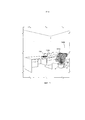
Фиг. 1A - относящийся к окружению вид в перспективе первого варианта осуществления системы беспроводной передачи энергии согласно настоящему изобретению.FIG. 1A is an environmental perspective view of a first embodiment of a wireless power transmission system according to the present invention.
Фиг. 1B - относящийся к окружению вид в перспективе второго варианта осуществления системы беспроводной передачи энергии согласно настоящему изобретению.FIG. 1B is an environmental perspective view of a second embodiment of a wireless power transmission system according to the present invention.
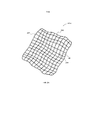
Фиг. 2A - вид в перспективе фазированной ячеистой антенной решетки для передатчика микроволнового излучения в системе беспроводной передачи энергии согласно настоящему изобретению.FIG. 2A is a perspective view of a phased mesh antenna array for a microwave transmitter in a wireless power transmission system according to the present invention.
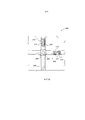
Фиг. 2B - схематическое изображение узла передачи энергии в системе беспроводной передачи энергии согласно настоящему изобретению.FIG. 2B is a schematic diagram of a power transmission unit in a wireless power transmission system according to the present invention.
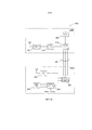
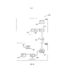
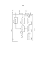
Фиг. 3A - структурная схема первого варианта осуществления системы беспроводной передачи энергии согласно настоящему изобретению.FIG. 3A is a block diagram of a first embodiment of a wireless power transmission system according to the present invention.
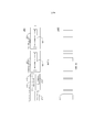
Фиг. 3B - структурная схема второго варианта осуществления системы беспроводной передачи энергии согласно настоящему изобретению.FIG. 3B is a block diagram of a second embodiment of a wireless power transmission system according to the present invention.
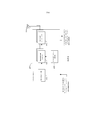
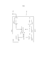
Фиг. 4 - структурная схема передатчика энергии альтернативного первого варианта осуществления.FIG. 4 is a block diagram of an energy transmitter of an alternative first embodiment.
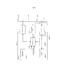
Фиг. 5 - структурная схема передатчика энергии альтернативного второго варианта осуществления.FIG. 5 is a block diagram of an energy transmitter of an alternative second embodiment.
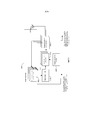
Фиг. 6 - структурная схема контроллера.FIG. 6 is a block diagram of a controller.
Фиг. 7 - структурная схема альтернативного приемника в соответствии с первым вариантом осуществления.FIG. 7 is a block diagram of an alternative receiver in accordance with the first embodiment.
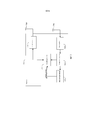
Фиг. 8 - структурная схема альтернативного приемника в соответствии со вторым вариантом осуществления.FIG. 8 is a block diagram of an alternative receiver in accordance with a second embodiment.
Фиг. 9 - структурная схема системы аккумуляторных батарей приемника.FIG. 9 is a block diagram of a receiver battery system.
Фиг. 10 - примерная схема линии электропередачи системы аккумуляторных батарей.FIG. 10 is an example circuit diagram of a power line of a battery system.
Фиг. 11 - альтернативный приемник в соответствии с первым вариантом осуществления.FIG. 11 is an alternative receiver in accordance with the first embodiment.
Фиг. 12 - альтернативный приемник в соответствии со вторым вариантом осуществления.FIG. 12 is an alternative receiver in accordance with a second embodiment.
Сходные ссылочные позиции обозначают соответствующие признаки единообразно на всех прилагаемых чертежах.Similar reference numerals designate corresponding features in the same manner in all accompanying drawings.
ОСУЩЕСТВЛЕНИЕ ИЗОБРЕТЕНИЯDETAILED DESCRIPTION OF THE INVENTION
Как показано на фиг. 1A-1B, настоящее изобретение включает в себя систему 100a или, в качестве альтернативы, систему 100b, для обеспечения беспроводной зарядки и/или основного источника энергии для электронных/электрических устройств, таких как дорожный компьютер 102, или тому подобное, посредством энергии микроволнового излучения. В любой из системы 100a или системы 100b, модулятор 101a передачи энергии или альтернативный модулятор 101b передачи энергии может получать рабочую энергию из сети электроснабжения переменного тока (A.C.) через силовой кабель P.O., подключенный к точке O подсоединения к сети электропитания. Частота передачи микроволнового излучения предпочтительно является имеющейся в распоряжении неконтролируемой FCC (федеральной комиссией связи) частотой, имеющей подходящую длину волны. Поскольку длина волны может ограничивать разрешающую способность фазированной антенной решетки 101a или альтернативной фазированной антенной решетки 101b, предпочтительная частота, хотя и не ограничивая выбор других частот, на которых может работать система, была выбрана имеющей значение 5,8 ГГц (длину волны 5,17 см), которое пригодно для передачи энергии на такие устройства, как дорожный компьютер, сотовый телефон, PDA (персональный цифровой секретарь), и т. д., через расстояния в масштабе помещения, аудитории, или тому подобного.As shown in FIG. 1A-1B, the present invention includes a
Как показано на фиг. 1A-3B, энергия микроволнового излучения фокусируется на устройстве, которое должно заряжаться источником 300 энергии, присоединенным к одному или более адаптивно фазируемых микроволновых излучателей 204 антенной решетки, то есть, антеннам или источникам излучения. Согласно настоящему изобретению, энергия микроволнового излучения из адаптивно фазируемых микроволновых излучателей 204 антенной решетки может фокусироваться на устройстве без необходимости знать местоположение устройства. Как показано на фиг. 1A, 1B и 3A-3B, предпочтительно высокоэффективные антенны 340 с встроенным выпрямителем (антенна с встроенным выпрямителем является выпрямляющей антенной, которая преобразует энергию микроволнового излучения непосредственно в электричество постоянного тока (D.C.); такие устройства известны в данной области техники и здесь дополнительно описываться не будут), при этом устройство, которое должно заряжаться, 102, принимает и выпрямляет энергию микроволнового излучения и использует ее для зарядки аккумуляторной батареи 370 посредством зарядки и/или для основного источника энергии для устройства 102, как определено управляющей логикой 350. В первом варианте осуществления, канал связи открывается между беспроводным источником 100a энергии и приемником 330b энергии в устройстве, которое должно заряжаться, 102, на частоте иной, чем частота, используемая для передачи энергии.As shown in FIG. 1A-3B, microwave energy is focused on a device that is to be charged by an
Устройство, которое должно заряжаться, 102, пересылает интенсивность принятого лучевого сигнала на антенне 340 через канал 110a связи в секцию приемника устройства 320 связи в передатчике 330a энергии системы 100a посредством сигнала из секции передатчика устройства 360 связи в приемнике 330b энергии. Эта информация используется управляющей логикой 310 системы 100a для повышения мощности, снижения мощности и настройки фаз передачи узлов 204 микроволнового излучателя антенной решетки до тех пор, пока максимальный пучок 301 энергии микроволнового излучения не излучается антенной решеткой 110a, как сообщается устройством, которое должно заряжаться, 102.The device to be charged, 102, sends the intensity of the received beam signal on the
Каждый излучатель 204, будучи присоединенным к одиночному источнику требуемой частоты передачи, может передавать сигнал с конкретным сдвигом по фазе, который является кратным числом π/2. Приращения фазы на π/2 являются только примерными, и возможны другие приращения фазы, такие как π/4, π/8, π/16 и т.п. Предпочтительно, мощность не настраивается за исключением того, что излучатель 204 может отключаться и включаться в требуемой фазе.Each
Как показано на фиг. 2A-2B, вертикальные и горизонтальные кабели пересекаются в каждом узле 204 антенной решетки. Эта конфигурация применяется к антенной решетке 101a или антенной решетке 101b. Внутри вертикального кабеля 202, провод 210 является линией питания нулевой фазы. Провод 212 является линией питания с фазой π/2, а провод 209 является вертикальной линией управления. Подобным образом, внутри горизонтального кабеля 200, провод 214 является линией питания с фазой π. Провод 216 является линией питания с фазой 3/2π, а провод 211 является горизонтальной линией управления. Линии 209 и 211 управления могут быть присоединены к контроллеру 310, чтобы управлять тем, какая фаза активна в любом заданном узле 204. Единое управление антенной может происходить в микросхеме 206, в то время как реальный источник излучения узла или антенна 208 может быть сформирован в качестве кругового элемента, окружающего геометрический центр узла 204. Должно быть понятно, что одиночный контроллер либо множество контроллеров могут управлять одним или более модуляторов передачи энергии.As shown in FIG. 2A-2B, vertical and horizontal cables intersect at each
Примерный алгоритм управляющей логики 210 для системы 100a может быть следующим: (1) приемник 330 энергии может использовать канал 110a связи для объявления своего присутствия всем передатчикам 330a поблизости; (2) передатчик 330a энергии может сообщать свое присутствие по каналу 1110a связи и начинать передачу только с одной из своих антенн 208 или узлов 204; (3) приемник 330b энергии может подтверждать прием слабого сигнала по каналу 110a связи; (4) передатчик 330a энергии включает другую антенну 208 или узел 204 с фазой по умолчанию ноль и может запрашивать приемник 330b по каналу 110a связи касательно интенсивности сигнала; (5) приемник 330b энергии может отправлять обратно сигнал, указывающий, что принятый сигнал является более высоким, таким же, или более низким, чем раньше; (6) если сигнал является более низким или таким же, как раньше, контроллер 310 может заставлять фазу в узле 204 увеличивать свою фазу на 1/2π и запрашивать еще одну передачу интенсивности сигнала; (7) этапы 5 и 6 повторяются для всех фаз; (8) если никакого увеличения интенсивности сигнала не наблюдается, то такой конкретный узел 204 выключается, и другой узел используется в последовательности операций, повторяющейся с этапа 4; (9) этапы 4-6 повторяются до тех пор, пока не будут использованы все узлы излучателей.An exemplary control logic algorithm 210 for system 100a may be as follows: (1) the power receiver 330 may use the communication channel 110a to announce its presence to all transmitters 330a nearby; (2) the energy transmitter 330a can communicate its presence through the communication channel 1110a and start transmitting from only one of its antennas 208 or nodes 204; (3) an energy receiver 330b can acknowledge the reception of a weak signal on a communication channel 110a; (4) the energy transmitter 330a includes another antenna 208 or node 204 with a default phase of zero and may request the receiver 330b via the communication channel 110a regarding signal strength; (5) the energy receiver 330b may send back a signal indicating that the received signal is higher, the same, or lower than before; (6) if the signal is lower or the same as before, the controller 310 may cause the phase at node 204 to increase its phase by 1 / 2π and request another transmission of signal intensity; (7) steps 5 and 6 are repeated for all phases; (8) if no increase in signal intensity is observed, then such a specific node 204 is turned off, and another node is used in the sequence of operations repeating from step 4; (9) steps 4-6 are repeated until all emitter nodes are used.
В другом примере этап (6) может включать в себя увеличение фазы в течение цикла трех фаз, который включает в себя 0, 1/2π и 5π/4 радиан. Таким образом, может определяться приближенная форма всей синусоидальной кривой. Соответственно, может определяться фазовый угол пиковой мощности. К тому же, при прибавлении настроенных антенн, следующая добавленная принимаемая антенной мощность может быть всего лишь небольшим процентом совокупной принимаемой мощности. Таким образом, добавление второй антенны может повышать мощность в 4 раза, а добавление 101-ой антенны может добавлять 2% мощности к мощности, а 1001ая может добавлять 0,2% к совокупной принимаемой мощности. Это может затруднять детектирование фактического получения/потери мощности от испытываемой антенны. Поэтому только несколько антенн могут получать питание во время цикла тестирования, и могут запоминаться фазы для каждой тестируемой антенны. Как только фазы полной антенной решетки были определены, все элементы могут включаться для передачи энергии.In another example, step (6) may include increasing the phase during a three-phase cycle, which includes 0, 1 / 2π and 5π / 4 radians. Thus, the approximate shape of the entire sinusoidal curve can be determined. Accordingly, the phase angle of the peak power can be determined. In addition, when tuned antennas are added, the next added antenna received power may be just a small percentage of the total received power. Thus, adding a second antenna can increase the capacity 4 times, and the addition 101st antenna may add 2% of the power to the power, and may add 1001 nd 0.2% to the total received power. This may make it difficult to detect the actual gain / loss of power from the antenna under test. Therefore, only a few antennas can receive power during the test cycle, and the phases for each antenna under test can be remembered. Once the phases of the full antenna array have been determined, all elements can be switched on to transmit energy.
В качестве альтернативы, все из антенн могут перенастраиваться по передаваемой энергии, возможно, посредством незначительного смещения их фаз около своих текущих значений и обнаружения влияния на принимаемый сигнал. Если происходит улучшение в одном направлении (например, при опережении или запаздывания фазы), фаза может продолжать вращаться/получать приращение, пока не будет улучшения ни с какой стороны. Это будет зависеть от способности обнаруживать изменение уровня принимаемой энергии для большой антенной решетки, иначе может потребоваться всю антенную решетку отключать и переустанавливать фазы заново.Alternatively, all of the antennas can be retuned according to the transmitted energy, possibly by slightly shifting their phases around their current values and detecting the effect on the received signal. If there is an improvement in one direction (for example, when the phase is ahead or late), the phase may continue to rotate / increment until there is improvement on either side. This will depend on the ability to detect changes in the level of received energy for a large antenna array, otherwise it may be necessary to turn off and reinstall the entire antenna array phase again.
Во втором варианте осуществления, как яснее всего показано на фиг. 2B и 3B, каждый элемент или узел 204 антенной решетки может быть установлен, чтобы принимать калибровочный сигнал из калибровочного передатчика 460 в системе 330b приема энергии. Каждый элемент или узел 204 антенной решетки может отправлять принятый калибровочный сигнал, детектированный в таком узле 204, в управляющую логику 310 через линию 303 данных. Затем любой из контроллера 310, контроллера 206 или оба контроллера в комбинации могут устанавливать каждый элемент или узел 204 антенной решетки на детектированную фазу для такого элемента в качестве фазы передачи, чтобы отправлять оптимизированную передачу 301 энергии обратно в приемник 330b энергии. В обоих вариантах 100a и 100b осуществления, устройство памяти конфигураций может находиться на действующей связи с логикой 310 контроллера, чтобы давать антенной решетке возможность передавать энергию в конкретное местоположение или «горячее пятно» без необходимости сначала связываться с устройством, которое должно заряжаться, 102. Этот признак полезен при отправке передачи 301 энергии на устройство, которое должно заряжаться, 102, когда устройство, которое должно заряжаться, 102, не имеет резервной мощности для установления канала связи 110a или 110b.In the second embodiment, as most clearly shown in FIG. 2B and 3B, each antenna array element or
В качестве альтернативы, второй вариант осуществления может работать, как изложено ниже, чтобы использовать двухсторонние возможности в антенне приемника и каждого передатчика, такие как в приемопередатчике. Контроллер может подготавливать каждый приемопередатчик для приема маякового сигнала из приемника энергии (например, устройства, которое должно заряжаться). Устройство, которое должно заряжаться, затем отправляет маяковый сигнал (например, калибровочный сигнал, который может быть той же самой частотой фазированной антенной решетки, например, посредством беспроводной связи между антенной решеткой и приемником, чтобы синхронизировать их тактовые генераторы), который проходит через все открытые пути передачи между устройством, которое должно заряжаться, и передатчиком энергии. Принятый сигнал на передатчике энергии эквивалентен сумме всех открытых путей передачи между антеннами приемника и передатчика, которые достигают каждой антенны в передатчике энергии, причем сумма каждого пути передачи добавляется к конкретному уровню мощности и фазе на каждой конкретной антенне передатчика энергии.Alternatively, the second embodiment may work as described below to take advantage of the two-way capabilities in the antenna of the receiver and each transmitter, such as in the transceiver. A controller may prepare each transceiver for receiving a beacon from an energy receiver (e.g., a device to be charged). The device that needs to be charged then sends a beacon (for example, a calibration signal, which can be the same phased array frequency, for example, via wireless communication between the antenna array and the receiver to synchronize their clocks), which goes through all open transmission paths between the device to be charged and the energy transmitter. The received signal at the energy transmitter is equivalent to the sum of all open transmission paths between the receiver and transmitter antennas that reach each antenna in the energy transmitter, the sum of each transmission path being added to a specific power level and phase at each specific antenna of the energy transmitter.
Каждая антенна в антенной решетке передатчика сравнивает поступающий сигнал с внутренним сигналом, чтобы детектировать принятую фазу. Как только принятая фаза установлена всеми антеннами передатчика, каждая антенна осуществляет обратную передачу с комплексно сопряженной величиной принятой фазы на своей полной мощности.Each antenna in the antenna array of the transmitter compares the incoming signal with an internal signal to detect the received phase. As soon as the received phase is set by all the antennas of the transmitter, each antenna performs a reverse transmission with the complex conjugate value of the received phase at its full power.
В дополнение, поскольку вышеприведенная настройка антенной решетки учитывает все возможные пути передачи (например, нет предположения, что имеется прямой открытый путь передачи между антенной решеткой и приемником, или что приемник перемещается, совершая плавное и прямолинейное движение в окружающей среде), любые изменения в отношении конфигурации окружения могут быть эквивалентны перемещению приемника или изменению физической конфигурации антенной решетки передатчика энергии. Поэтому может постоянно требоваться частая перенастройка антенной решетки (например, 10 или более раз в секунду).In addition, since the above antenna array configuration takes into account all possible transmission paths (for example, there is no assumption that there is a direct open transmission path between the antenna array and the receiver, or that the receiver moves in a smooth and rectilinear motion in the environment), any changes in relation environmental configurations may be equivalent to moving the receiver or changing the physical configuration of the antenna array of the energy transmitter. Therefore, frequent reconfiguration of the antenna array (e.g., 10 or more times per second) may constantly be required.
Поскольку перенастройка антенной решетки требует отключения отправляемой энергии, чтобы «слушать» маяковый сигнал приемника, может быть потеряно время, которое могло бы быть использовано для питания антенной решетки. Соответственно, антенная решетка может снижать частоту перенастройки, когда уровень мощности на приемнике не изменяется значительно, чтобы довести до максимума доставку энергии на приемник. Когда прием энергии на приемнике прекращается, антенная решетка может повышать частоту обновлений до тех пор, пока мощность приемника вновь не стабилизируется. Могут быть установлены конкретные ограничения по частоте настройки, такие как минимум 10 tps (настроек в секунду) до максимум 500 tps. Перенастройка с очень высокой частотой могла бы понижать эффективность передачи энергии за пределы применимости.Since reconfiguring the antenna array requires turning off the energy sent in order to “listen” to the beacon signal of the receiver, time could be lost that could be used to power the antenna array. Accordingly, the antenna array can reduce the frequency of reset when the power level at the receiver does not change significantly to maximize the energy delivery to the receiver. When the reception of energy at the receiver ceases, the antenna array can increase the refresh rate until the receiver power is stabilized again. Specific tuning frequency limits can be set, such as at least 10 tps (settings per second) up to a maximum of 500 tps. Reconfiguration with a very high frequency could reduce the efficiency of energy transfer beyond the limits of applicability.
В качестве альтернативы, настройка некоторого количества (n) антенн может выполняться, как изложено ниже. Все n антенн могут быть отключены. Одна из n антенн затем включается и остается включенной в качестве точки отсчета для каждой из других n антенн для настройки. Каждая из оставшихся n антенн затем включается, регистрируется их оптимальная фаза, а затем они отключаются. Когда эта последовательность выполняется на n-ой антенне, все антенны включены на своих соответствующих оптимальных фазах.Alternatively, tuning in a number of (n) antennas may be performed as described below. All n antennas can be turned off. One of the n antennas is then turned on and stays on as a reference point for each of the other n antennas for tuning. Each of the remaining n antennas is then turned on, their optimal phase is recorded, and then they are turned off. When this sequence is performed on the nth antenna, all antennas are turned on at their respective optimum phases.
Что касается первого варианта осуществления, имеющего перемещающийся приемник, может быть необходимым перенастраиваться всем из антенн передатчика, например, посредством незначительного перемещения их фаз около текущих значений и детектирования влияния на принимаемый сигнал. Если он улучшается в одном направлении, вращение/приращение фазы продолжается до тех пор, пока не будет улучшений с той или другой стороны. Это может зависеть от способности обнаруживать изменение уровня принимаемой энергии для большой антенной решетки, иначе может потребоваться отключить и переустановить фазы всей антенной решетки с начала.As for the first embodiment having a moving receiver, it may be necessary to retune all of the transmitter antennas, for example, by slightly moving their phases near current values and detecting the effect on the received signal. If it improves in one direction, the rotation / phase increment continues until there are improvements on one side or the other. This may depend on the ability to detect changes in the level of received energy for a large antenna array, otherwise it may be necessary to disconnect and reinstall the phases of the entire antenna array from the beginning.
Примерная антенная решетка 101a или 101b может быть сеточной решеткой 30x30 приблизительно в один метр по каждой стороне, причем, каждое пересечение проводов имеет одиночную передающую антенну 204. Предпочтительно, сетка 101a или 101b решетки выполнена из гибких/мягких материалов. Гибкость материала сетки позволяет пользователю физически конфигурировать сетку 101a или 101b микроволнового излучателя решетки по существу неравномерным некомпланарным образом, то есть, распределенным, но не плоским, чтобы, например, минимизировать зеркальные фокусные точки, вызываемые плоскими двухмерными решетками, и слепые пятна, которые обычно возникают в плоских регулярно размещенных антенных решетках, имеющих дискретные сдвиги по фазе. Как показано на фиг. 1A-1B, любая из антенной решетки 101a или антенной решетки 101b является достаточно гибкой, так чтобы она могла драпировать опорную конструкцию, такую как комнатное растение S, чтобы давать предпочтительно неравномерную некомпланарную конфигурацию.An
Таким образом, обратноквадратичный закон успешно оспаривается, поскольку фазированная антенна является направленной, тем самым создавая усиление посредством конструктивно фазированного лучевого сигнала, который может приниматься на приемном устройстве 102. Более того, использование фазированной антенной решетки, такой как 101a или 101b, избегает необходимости использования более громоздкого неприглядного устройства, такого как физическая направленная антенна, то есть тарельчатая антенна, директорная антенна или т.п. Дополнительно, вследствие эффективности процесса передачи энергии, низкая мощность может использоваться для передачи, так что электромагнитный (EM) сигнал может иметь большую часть своей интенсивности вблизи приемного устройства вместо распространения повсюду, чтобы не наносить вред окружающей среде и не порождать помехи устройствам, расположенным где-то в другом месте.Thus, the inverse-square law is successfully challenged because the phased antenna is directional, thereby generating amplification through a structurally phased beam signal that can be received at the
Как только сигнал принят и его энергия имеется в распоряжении, процесс преобразования переменного тока приблизительно 5,80 ГГц, поступающего с антенны, в постоянный ток для зарядки аккумуляторной батареи 370, мощного накопительного конденсатора или т.п. выполняется низковольтными выпрямителями, способными к такой задаче. Эти выпрямители могут быть основаны на диодах Шоттки малой площади или использовать резонанс с колебательным контуром 5,80 ГГц в той же фазе, что и принятый сигнал, таким образом, усиливая свою мощность до точки преодоления падения напряжения диодов, используемых в выпрямительной части антенны 340 с встроенным выпрямителем. Следует отметить, что многочисленные устройства могут заряжаться посредством совместного использования по времени антенной решетки или посредством суперпозиции фаз антенн, чтобы имитировать многолучевую конфигурацию.Once the signal has been received and its energy is available, the process of converting an alternating current of approximately 5.80 GHz from the antenna into direct current to charge the
Механизм зарядки, описанный выше, работает, когда передатчик и приемник осуществляют связь друг с другом. Однако способ для зарядки приемника, который не имеет возможности поддерживать связь, также может быть полезным. Для достижения этого, могут быть установлены местоположение или местоположения, которые будут принимать периодический импульс передачи энергии.The charging mechanism described above works when the transmitter and receiver communicate with each other. However, a method for charging a receiver that is unable to communicate can also be useful. To achieve this, a location or locations can be set that will receive a periodic pulse of energy transfer.
В одном из примеров того, каким образом заряжать устройство, не имеющее мощности аккумуляторной батареи, маяковое устройство или устройство возобновления работы (не показаны) могут быть помещены в местоположении для приема периодического импульса передачи энергии или по запросу от пользователя. Маяковое устройство поддерживает связь с сеткой передачи энергии, к примеру, посредством передачи маякового сигнала, и сетка передачи энергии распознает конфигурацию фаз такого маякового сигнала в качестве местоположения для передачи периодического импульса передачи энергии (например, односекундного импульса каждые десять минут, или импульса 0,1 секунды каждую минуту с односекундным импульсом каждые десять минут). Маяковый сигнал, передаваемый с маякового устройства, может отражаться и/или преломляться внутри различных сред до его прибытия в сетку передачи энергии. Соответственно, многочисленные маяковые сигналы могут приниматься сеткой передачи энергии. Когда сетка передачи энергии принимает один или более маяковых сигналов, может устанавливаться открытый путь (пути) передачи из местоположения маякового сигнала к сетке передачи энергии.In one example of how to charge a device that does not have battery power, a beacon device or a resume device (not shown) can be placed at a location to receive a periodic pulse of power transmission or upon request from a user. The beacon device communicates with the power transmission grid, for example, by transmitting a beacon signal, and the energy transmission grid recognizes the phase configuration of such a beacon signal as a location for transmitting a periodic power transmission pulse (for example, a one second pulse every ten minutes, or a 0.1 pulse seconds every minute with a one second pulse every ten minutes). The beacon signal transmitted from the beacon device may be reflected and / or refracted inside different media before it arrives at the power transmission grid. Accordingly, multiple beacon signals can be received by the power transmission grid. When the power transmission grid receives one or more beacon signals, an open transmission path (s) from the location of the beacon signal to the power transmission grid can be established.
Сетка передачи энергии затем может агрегировать маяковые сигналы, чтобы воссоздавать форму сигнала переданного маякового сигнала. По этой воссозданной форме сигнала, сетка передачи энергии затем может передавать импульс передачи энергии, например, в качестве обратной формы воссозданной формы сигнала для выдачи импульса энергии в местоположении маякового устройства. В одном из вариантов осуществления, обратная форма сигнала может определяться взятием комплексно сопряженного или математически эквивалентного преобразования форм сигнала, принимаемых от маякового устройства. Маяковое устройство может отключаться, как только установлено местоположение для приема периодического импульса передачи энергии.The energy transfer grid may then aggregate beacon signals to recreate the waveform of the transmitted beacon. According to this reconstructed waveform, the energy transfer grid can then transmit an energy transfer pulse, for example, as the inverse of the reconstructed waveform to provide an energy pulse at the location of the beacon device. In one embodiment, the reverse waveform may be determined by taking a complex conjugate or mathematically equivalent waveform conversion received from the beacon device. The beacon device can be turned off as soon as the location for receiving a periodic pulse of energy transfer is established.
Устройство, которое должно заряжаться, 102, которое не имеет мощности аккумуляторной батареи, затем может быть помещено в таком местоположении, где оно будет принимать периодический импульс передачи энергии до тех пор, пока оно не получит достаточную мощность для поддержания связи с сеткой передачи энергии, чтобы подвергаться процессу зарядки, описанному выше. Устройство затем может перемещаться прочь из такого местоположения.The device to be charged, 102, which does not have battery power, can then be placed at a location where it will receive a periodic energy transfer pulse until it receives sufficient power to communicate with the energy transfer network so that undergo the charging process described above. The device can then move away from that location.
Как только устройство, которое должно заряжаться, 102, перемещено из одного местоположения в другое, или перемещена сетка передачи энергии, сетка передачи энергии может перенастраивать себя (например, перестраивать передающие антенны), чтобы установить наилучшую мощность передачи на устройство, которое должно заряжаться, 102. Эта перенастройка может происходить в ответ на сообщение от устройства 102 о падении мощности или с равными интервалами (например, 1 мс - 10 с). Однако равный интервал может быть укорачиваться или удлиняться в зависимости от того, насколько хорошо мощность сигнала поддерживается приемником, наряду с продолжением регулярно осуществлять перенастройку несмотря на отсутствие падения мощности.Once the device that needs to be charged, 102, is moved from one location to another, or the power transmission grid is moved, the power transmission grid can reconfigure itself (for example, rebuild the transmit antennas) to establish the best transmit power to the device that needs to be charged, 102 This reconfiguration may occur in response to a message from the
Антенны передатчика также могут принимать форму включения схемы в одиночную микросхему и шлейфового подключения микросхем проводами для создания длинных полос «фазированных проводов», которые могут конфигурироваться и использоваться в различных формах и конструкциях. При конструировании сложных решеток с тысячами антенн и ассоциированных контроллеров посредством полос микросхем «фазового управления», провода между микросхемами могут служить в качестве путей передачи данных, соединяющих микросхемы с общим контроллером, причем одновременно провода также могут действовать в качестве самих передающих/приемных антенн. Каждая микросхема может иметь большее количество проводов, выходящих из нее, действующих в качестве антенн. Каждой антенне может быть задан адрес (например, a, b, c, и тому подобное), предоставляя микросхеме возможность управлять фазой каждой антенны независимо от других. Дополнительно, провода могут быть сконфигурированы во всех разновидностях компоновок, в зависимости от имеющегося в распоряжении пространства, поскольку настройка антенной решетки происходит независимо от местоположений и компоновок антенн.Transmitter antennas can also take the form of incorporating a circuit into a single chip and looping the circuits with wires to create long strips of “phased wires” that can be configured and used in various shapes and designs. When constructing complex arrays with thousands of antennas and associated controllers using “phase control” microcircuit strips, the wires between the microcircuits can serve as data transmission paths connecting the microcircuits to a common controller, while the wires can also act as transmitting / receiving antennas themselves. Each microcircuit may have a larger number of wires emerging from it, acting as antennas. Each antenna can be given an address (for example, a, b, c, and the like), giving the chip the ability to control the phase of each antenna independently of the others. Additionally, the wires can be configured in all kinds of layouts, depending on the available space, since the antenna array is set up independently of the locations and layouts of the antennas.
Поскольку контроллеры микросхем антенн соединены через короткие провода, провода могут использоваться в качестве антенны несколькими способами. Например, сами провода могут возбуждаться осциллятором и/или усилителями, или экран может использоваться вокруг проводов, причем сам экран возбуждается и используется в качестве антенны, таким образом, предохраняя провода связи от экранирования сигнала в многослойных антенных решетках.Since the antenna chip controllers are connected via short wires, the wires can be used as an antenna in several ways. For example, the wires themselves can be excited by an oscillator and / or amplifiers, or the screen can be used around the wires, and the screen itself is excited and used as an antenna, thus protecting the communication wires from signal shielding in multilayer antenna arrays.
Фиг. 4 - структурная схема передатчика альтернативного первого варианта осуществления. Передатчик может быть контроллером 400 антенны, который включает в себя управляющую логику 410, фазосдвигающие устройства 420 (в количестве N), генератор/умножитель 430 сигнала, усилители 440 (в количестве N) и (N) антенн 450. Контроллер 400 антенны принимает сигналы величины мощности и управления опорной частотой, а также другие команды и сигналы связи, по общей шине из одиночного контроллера, который управляет всеми контроллерами антенн, или из предыдущего контроллера 400 антенны. Сигнал величины мощности, например, может приниматься источником питания передатчика 400 (не показан), сигнал управления опорной частотой может приниматься генератором/умножителем 430 сигнала, а сигналы связи и команды могут приниматься управляющей логикой 410. В случае, где каждый предыдущий контроллер 400 антенны выдает сигналы величины мощности и управления опорной частотой, шина, несущая такие сигналы, может продолжаться в следующий контроллер 400 антенны. Управляющая логика 400 может управлять фазосдвигающим устройством 420, чтобы заставлять его настраивать фазу усилителей 440. Генератор/умножитель сигнала принимает сигнал с шины, например, на 10 МГц, и преобразует его, например, в 2,4, 5,8 ГГц и т.п. для беспроводной связи.FIG. 4 is a block diagram of a transmitter of an alternative first embodiment. The transmitter may be an
Фиг. 5 - структурная схема передатчика альтернативного второго варианта осуществления. Передатчик может быть контроллером 500 антенны, который включает в себя управляющую логику 510, фазосдвигающие устройства 520 (в количестве N), генератор/умножитель 530 сигнала, приемопередатчики 540 (в количестве N), (N) антенн 550 и фазовые компараторы 560 (в количестве N). Приемопередатчики 540 принимают калибровочные или маяковые сигналы из приемников и пересылают сигнал в фазовые компараторы 560. Фазовые компараторы 560 определяют фазу принятых сигналов своих соответствующих приемопередатчиков 540 и определяют оптимальный фазовый угол, под которым следует передавать сигнал величины мощности. Эта информация выдается в управляющую логику 510, которая затем побуждает фазосдвигающее устройство 520 устанавливать фазу (например, на комплексно сопряженной величине принятого маякового/калибровочного сигнала) приемопередатчиков и передавать энергию с такой установленной фазой. Генератор/умножитель 530 сигнала выполняет функцию, по существу подобную генератору/умножителю 430 сигнала контроллера 400 антенны. В дополнение, сигналы шины подобны таковым в передатчике 400, причем, сигналы, например, принимаются эквивалентными компонентами в передатчике 500.FIG. 5 is a block diagram of a transmitter of an alternative second embodiment. The transmitter may be an
Фиг. 6 - структурная схема контроллера 600, например, для управления контроллерами антенны по фиг. 4 и 5. Контроллер 600 включает в себя управляющую логику 610, источник 620 энергии, блок 630 связи, присоединенный к антенне 660, тактовый генератор 640 опорного сигнала, присоединенный к антенне 670, и контроллер 650 шины. Управляющая логика 610 управляет контроллером 650, шины, который передает сигналы с M шин на количество M контроллеров антенны (например, 400 и 500). Источник 620 энергии предусматривает источник питания для контроллера 650 шины. Блок 630 связи передает и принимает данные из приемника через свою соответствующую антенну 660. Тактовый генератор 640 опорного сигнала передает опорный сигнал в другие контроллеры и также может отправлять/принимать передачи с приемника для синхронизации. Один контроллер 600 может использоваться для управления всеми антеннами передатчика, или несколько контроллеров 600 могут использоваться, где один контроллер 600 управляет группой антенн. Дополнительно, следует отметить, что хотя показаны отдельные блоки связи и тактовый генератор опорного сигнала, имеющие соответствующие антенны, функциональные возможности могут быть включены в один блок (например, блок 630 связи).FIG. 6 is a block diagram of a
Фиг. 7 - структурная схема альтернативного приемника 700 в соответствии с первым вариантом осуществления. Приемник 700 включает в себя управляющую логику 710, аккумуляторную батарею 720, блок 730 связи и ассоциированную антенну 760, измеритель 740 мощности, а также выпрямитель и ассоциированную антенну 750. Управляющая логика 710 передает и принимает сигнал данных на несущей частоте данных из блока 730 связи. Этот сигнал данных может быть в форме сигнала интенсивности энергии, передаваемого через побочный канал, описанный выше. Выпрямитель 750 принимает сигнал передачи энергии из передатчика энергии, который подается через измеритель 740 мощности в аккумуляторную батарею 720 для зарядки. Измеритель 740 мощности измеряет интенсивность принятого сигнала мощности и снабжает управляющую логику 710 этим измерением. Управляющая логика 710 также может принимать уровень мощности аккумуляторной батареи из самой аккумуляторной батареи 720.FIG. 7 is a block diagram of an
Приемник 700, например, может синхронизироваться с контроллером, вынуждая контроллер 600 передавать сигнал основной частоты через антенну 670. Приемник 700 затем может использовать сигнал для синхронизации маякового сигнала или калибровочного сигнала, который приемник передает обратно в контроллер 600. Эта технология также может использоваться с многочисленными контроллерами. То есть, в тех случаях, когда используются многочисленные передающие антенные решетки, контроллеры могут синхронизироваться друг с другом посредством использования сигнала основной частоты, отправляемого из одного из контроллеров.The
Фиг. 8 - структурная схема альтернативного приемника 800 в соответствии со вторым вариантом осуществления. Приемник 800 включает в себя управляющую логику 810, аккумуляторную батарею 820, блок 830 связи и ассоциативно связанную антенну 870, измеритель 840 мощности, выпрямитель 850, генератор 860 маякового сигнала и ассоциативно связанную антенну 880 и переключатель 865, присоединяющий выпрямитель 850 или генератор 860 маякового сигнала к ассоциативно связанной антенне 890. Выпрямитель 850 принимает сигнал передачи энергии из передатчика энергии, который подается через измеритель 840 мощности в аккумуляторную батарею 820 для зарядки. Измеритель 840 мощности измеряет интенсивность принятого сигнала энергии и снабжает управляющую логику 810 этим измерением. Управляющая логика 810 также может принимать уровень мощности аккумуляторной батареи из самой аккумуляторной батареи 820. Управляющая логика 810 также может передавать/принимать, через блок 830 связи, сигнал данных на несущей частоте данных, такой как у тактового генератора опорного сигнала для тактовой синхронизации. Генератор 860 маякового сигнала передает маяковый сигнал или калибровочный сигнал с использованием любой из антенн 880 или 890. Хотя аккумуляторная батарея 820 показана для зарядки и для выдачи энергии в приемник 800, приемник также может принимать энергию непосредственно из выпрямителя 850. Это может происходить в дополнение к выпрямителю 850, выдающему зарядный ток в аккумуляторную батарею 820, вместо обеспечения зарядки. Использование многочисленных антенн является одной из примерных реализаций, и конструкция может быть сокращена до одной совместно используемой антенны.FIG. 8 is a block diagram of an
Поскольку схемы управления антенной передатчика и схемы питания и управления приемника могут быть построены как интегральные схемы (IC) и могут совместно использовать несколько ключевых компонентов схемы, две функциональных возможности микросхемы могут быть сконструированы как одиночная микросхема, и посредством выбора разного монтажа или конфигурации микросхема может функционировать в качестве передатчика либо приемника. То есть, одна и та же микросхема с определенными включенными или выключенными частями может использоваться в качестве контроллера передающей антенны или контроллера приемника. Это может снижать себестоимость создания и испытания двух разных микросхем, а также экономить затраты на изготовление микросхем, которые могут быть значительными.Since transmitter antenna control circuits and receiver power and control circuits can be built as integrated circuits (ICs) and can share several key components of the circuit, the two functionality of the chip can be designed as a single chip, and by choosing a different mounting or configuration, the chip can function as a transmitter or receiver. That is, the same chip with certain parts turned on or off can be used as a transmitter antenna controller or a receiver controller. This can reduce the cost of creating and testing two different chips, as well as save the cost of making chips, which can be significant.
Как обсуждено выше, форма сетки передачи может приобретать многие разновидности. Соответственно, упаковка антенны могла бы быть достаточно близкой к приблизительно от половины длины волны передаваемого сигнала энергии до нескольких длин волн. Двумерные компоновки могут выполняться, чтобы позволить укладывать антенную решетку под ковром или драпировать поверх теплоизоляции чердака. Например, могут применяться многочисленные широкие провода (например, узкие полосы двухмерной антенной решетки), которые содержат многочисленные передающие антенны. Эти широкие провода могут устанавливаться на настиле пола или внутри стен. В качестве альтернативы, сетка передачи энергии может быть в форме рамочной антенны или любой другой форме.As discussed above, the shape of the transmission grid can take many forms. Accordingly, the packaging of the antenna could be close enough to approximately half the wavelength of the transmitted energy signal to several wavelengths. Two-dimensional arrangements can be made to allow the antenna array to be laid under the carpet or draped over the attic insulation. For example, numerous wide wires (eg, narrow bands of a two-dimensional antenna array) that contain multiple transmit antennas can be used. These wide wires can be installed on flooring or inside walls. Alternatively, the power transmission grid may be in the form of a loop antenna or any other form.
Трехмерные компоновки могли бы располагать большим количеством антенн и могли бы быть включены в традиционные формы, такие как офисные потолочные плитки, двери, картины и ТВ - таким образом, делая антенную решетку невидимой и ненавязчивой. К тому же, сетчатые антенные решетки могут быть сформированы в нескольких слоях, уложенных стопой один за другим, предоставляя возможность для антенны более высокой плотности. В этом примере, антенная решетка действует подобно «фазированному объему», имеющему одиночный направленный вперед пучок с минимальным значением зеркального пучка позади него. Зеркальный пучок может уменьшаться по мере того, как возрастает толщина фазированного объема.Three-dimensional layouts could have a large number of antennas and could be included in traditional forms such as office ceiling tiles, doors, paintings and TVs - thus making the antenna array invisible and unobtrusive. In addition, mesh antenna arrays can be formed in several layers stacked one after the other, making it possible for a higher density antenna. In this example, the antenna array acts like a “phased volume” having a single forward beam with a minimum mirror beam behind it. The mirror beam may decrease as the thickness of the phased volume increases.
То есть, идеально плоские фазированные антенные решетки, использующие однонаправленные антенны могут создавать два «образа» сформированных волновых фронтов симметрично вокруг плоскости антенной решетки (например, когда имеется свободное пространство или идентичная среда на противоположных сторонах антенной решетки). Это могло бы иметь нежелательные последствия уменьшения доставки энергии (например, 50% энергии, уходящей в заднюю плоскость) и, таким образом, снижения эффективности передачи. Компоновка антенн антенной решетки в неплоской форме может уменьшать этот симметричный волновой фронт, даже если она имеет симметричную конструкцию 3-мерной антенной решетки, вследствие того обстоятельства, что антенны будут иметь разные фазы на симметричных сторонах антенной решетки, делая сигнал несимметричным и не «зеркальным».That is, perfectly flat phased antenna arrays using unidirectional antennas can create two “images” of generated wave fronts symmetrically around the plane of the antenna array (for example, when there is free space or an identical medium on opposite sides of the antenna array). This could have the undesirable consequences of reducing energy delivery (for example, 50% of the energy leaving in the back plane) and, thus, reducing the transmission efficiency. Layout of antennas of the antenna array in non-planar form can reduce this symmetric wavefront, even if it has a symmetrical design of a 3-dimensional antenna array, due to the fact that the antennas will have different phases on the symmetrical sides of the antenna array, making the signal asymmetric and not “mirror” .
Когда антенная решетка настраивается по фазе на конкретный приемник, каждая антенна в антенной решетке имеет конкретную фазу, с которой она осуществляет передачу, чтобы создавать сигнал, который достигает такого конкретного приемника. Два или более приемников могут быть сконфигурированы для приема энергии посредством одного или комбинации следующих методов.When the antenna array is phase-tuned to a specific receiver, each antenna in the antenna array has a specific phase with which it transmits to create a signal that reaches such a specific receiver. Two or more receivers may be configured to receive energy through one or a combination of the following methods.
В первом методе, доставка энергии с разделением времени может использоваться между разными приемниками. Это может делаться посредством настройки антенн в антенной решетке на один приемник, а затем переключения на следующий приемник, давая каждому приемнику равное (или неравное) время. Настройка антенной решетки на каждый приемник может производиться из памяти или посредством перенастройки антенной решетки с использованием процесса, подобного методу второго варианта осуществления.In the first method, time-sharing energy delivery can be used between different receivers. This can be done by tuning the antennas in the antenna array to one receiver, and then switching to the next receiver, giving each receiver equal (or unequal) time. Tuning the antenna array to each receiver can be done from memory or by reconfiguring the antenna array using a process similar to the method of the second embodiment.
В другом методе может использоваться фазовая модуляция всех антенн антенной решетки для создания многочисленных энергетических пятен. Для каждой антенны, принятый сигнал является вектором с фазой, имеющей значение принятого угла, в то время как амплитуда является уровнем мощности принятого сигнала. Чтобы создать отраженный сигнал к множеству приемников, фаза передачи может определяться как имеющая значение угла суммы принятых векторов. Хотя не обязательно использовать величину принятого сигнала и передавать с каждой антенны с нормальной мощностью передачи, чтобы создать смещенный многофокусный сигнал, который работает лучше, когда учитываются сигналы многолучевого распространения, может детектироваться пиковая мощность принятого сигнала с каждого приемника, и сложение векторов может смещаться посредством масштабирования векторов по нормированной шкале (например, пиковая мощность с каждого приемника может учитываться с величиной 1,0 для пиковой мощности). Сложение векторов может гарантировать, что каждая антенна выдает большую энергию в приемник, на который она подает большую мощность, или, в качестве альтернативы, с которого принимает большую мощность.Another method may use phase modulation of all antenna arrays to create multiple energy spots. For each antenna, the received signal is a vector with a phase having a value of the received angle, while the amplitude is the power level of the received signal. In order to create a reflected signal to a plurality of receivers, the transmission phase can be determined as having a value of the angle of the sum of the received vectors. Although it is not necessary to use the magnitude of the received signal and transmit from each antenna with normal transmit power to create a biased multifocal signal that works better when multipath signals are taken into account, the peak power of the received signal from each receiver can be detected, and the addition of vectors can be shifted by scaling vectors on a normalized scale (for example, the peak power from each receiver can be taken into account with a value of 1.0 for peak power). The addition of vectors can ensure that each antenna delivers more energy to the receiver to which it delivers more power, or, alternatively, from which it receives more power.
Совместное использование антенн является еще одной технологией. Посредством разделения всей антенной решетки на многочисленные антенные подрешетки, каждая может выделять свою энергию конкретному приемнику. Этот подход может быть полезным, когда антенная решетка является достаточно большой, чтобы быть эффективной при разделении.Sharing antennas is another technology. By dividing the entire antenna array into multiple antenna sublattices, each can release its energy to a specific receiver. This approach can be useful when the antenna array is large enough to be effective in separation.
Отдельные антенные решетки могут использоваться в унисон, где отдельные блоки антенной решетки синхронизируют свои основные тактовые импульсы сигнала с использованием совместно используемой эфирной радиочастоты для реализации непрерывного сигнала из обозначенного «ведущего» блока, позволяя всем «ведомым» блокам контроллера передатчика добавлять свои сигналы когерентным образом. Это позволяет распределять отдельные антенные решетки в среде, давая пользователям гибкость при компоновке многочисленных антенных решеток по зданию, жилым помещениям, производственным предприятиям или офисам. Во время установки этих контроллеров, установщик/программа управления может связывать разные антенные решетки контроллера друг с другом, назначая ведущий блок вместе с последовательностями обхода отказа, так что независимо от того, сколько антенных решеток выходят из строя, система будет продолжать работу с использованием имеющихся в распоряжении антенных решеток. Например, антенные решетки могут устанавливаться посредством синхронизации их с использованием квантовых часов. То есть, отдельные блоки антенной решетки могут работать без синхронизации на основной частоте посредством использования точных квантовых часов (например, с точностью лучше 1:10˄10), если отдельные блоки антенной решетки используют одиночную частоту, чтобы применять для передачи энергии. В этом случае, они были бы совпадающими по фазе в течение долей секунды, позволяя поддерживать когерентность фазы/сигнала.Separate antenna arrays can be used in unison, where individual antenna arrays blocks synchronize their main signal clocks using a shared broadcast radio frequency to realize a continuous signal from the designated “master” unit, allowing all “slave” transmitter controller units to add their signals in a coherent manner. This allows you to distribute individual antenna arrays in the environment, giving users the flexibility to layout multiple antenna arrays across a building, residential premises, manufacturing plants or offices. During the installation of these controllers, the installer / control program can connect the different antenna arrays of the controller to each other, assigning the master unit along with the failover sequences, so that no matter how many antenna arrays fail, the system will continue to work using the available disposal of antenna arrays. For example, antenna arrays can be installed by synchronizing them using a quantum clock. That is, individual blocks of the antenna array can operate without synchronization at the fundamental frequency by using the exact quantum hours (e.g., with an accuracy better than 1:10 10) if the individual blocks of the antenna array using a single frequency to be used for power transmission. In this case, they would be in phase for a split second, allowing phase / signal coherence to be maintained.
В другом методе передачи энергии передатчик может отправлять регулярный сигнал в побочном канале связи, широковещательно передавая свое присутствие всем приемникам. Если есть другие передатчики поблизости, это позволяет использовать одну из согласованных частот или избегать наложений сигналов посредством контроля сигналов другого передатчика. Эти широковещательные оповещения могут меняться по частоте от нескольких в минуту до менее одного в минуту. Приемник может отправлять сигнал, оповещающий о его присутствии, а передатчики могут согласовывать, какой сигнал является наиболее подходящим для передачи энергии. Как только решение принято, приемник «синхронизируется» с одиночным передатчиком. Это может требовать, чтобы каждый передатчик был определен в качестве логического (одноконтроллерного) устройства - которое может быть составлено из многочисленных связанных передатчиков. Если контроллер обнаруживает, что огибающая мощности изменилась (то есть, приемник не требует ту же мощность), контроллер может продолжать предоставлять мощность, так чтобы приемник не выходил из строя.In another method of transmitting energy, a transmitter can send a regular signal on a side channel, broadcasting its presence to all receivers. If there are other transmitters nearby, this allows you to use one of the agreed frequencies or to avoid overlapping signals by monitoring the signals of the other transmitter. These broadcast alerts can vary in frequency from a few per minute to less than one per minute. The receiver can send a signal indicating its presence, and the transmitters can coordinate which signal is most suitable for transmitting energy. Once the decision is made, the receiver is “synchronized” with a single transmitter. This may require that each transmitter be defined as a logical (single-controller) device - which can be composed of multiple connected transmitters. If the controller detects that the power envelope has changed (that is, the receiver does not require the same power), the controller can continue to provide power so that the receiver does not fail.
В другом методе передачи энергии передатчики могут устанавливаться так, что они были открыты для подачи энергии на любое нуждающееся устройство, или они могут формировать пары с устройствами, которые они должны обслуживать. Формирование пар избегает проблемы непреднамеренного заимствования энергии соседями друг у друга, что могло бы оказывать влияние на эффективность с точки зрения владельца передатчика. Когда передатчик сталкивается с многочисленными приемниками, может быть желательным устанавливать иерархию для приоритизации, к примеру, сначала давая энергию наиболее нуждающимся устройствам, что могло бы устанавливаться согласно одному или более предопределенных критериев.In another method of transmitting energy, the transmitters can be mounted so that they are open to supply energy to any device in need, or they can pair with devices that they need to service. The formation of pairs avoids the problem of unintentional borrowing of energy by neighbors from each other, which could affect the efficiency from the point of view of the owner of the transmitter. When a transmitter is confronted with multiple receivers, it may be desirable to establish a hierarchy for prioritization, for example, by first supplying energy to the most needed devices, which could be set according to one or more predetermined criteria.
Например, некоторые из критериев могут включать в себя следующее: устройство имеет критическую важность для его владельца (например, сотовый телефон в противоположность игрушке); устройство типично не находится в течение всего дня вблизи передатчика (например, пульт дистанционного управления ТВ по сравнению с сотовым телефоном); или обнаружено, что устройству необходимо немедленное питание, или оно перестанет действовать. Такие устройства могут наделяться более высоким приоритетом над другими, пока они не достигнут некритической энергии. В качестве альтернативы, может использоваться настроенный пользователем приоритет, в силу чего, пользователь решает, какое устройство должно получать наивысший приоритет.For example, some of the criteria may include the following: the device is critical to its owner (for example, a cell phone as opposed to a toy); the device is typically not located all day near the transmitter (for example, a TV remote control compared to a cell phone); or it is detected that the device needs immediate power, or it stops functioning. Such devices can be given higher priority over others until they reach non-critical energy. Alternatively, a user-configured priority can be used, whereby the user decides which device should receive the highest priority.
Примерное предпочтение приоритизации, описанное выше, может предварительно устанавливаться в системе передатчика (например, в управляющей логике) с возможностью отменяться установщиком антенной решетки, гарантируя, что система осуществляет передачу согласно приоритетам, установленным владельцами/пользователями. Владелец или пользователь также может требовать, должна ли быть антенная решетка открыта, чтобы подавать энергию на любое устройство, или желательно регистрировать конкретные устройства с наивысшим приоритетом или наименьшим приоритетом. Дополнительно, пользователю или владельцу может быть желательным определять, поддерживать или нет питание для конкретного устройства, даже если оно является перемещающимся.The approximate prioritization preference described above can be pre-installed in the transmitter system (for example, in the control logic) with the ability to be canceled by the installer of the antenna array, ensuring that the system transmits according to the priorities set by the owners / users. The owner or user may also require that the antenna array must be open to supply power to any device, or it is desirable to register specific devices with the highest priority or lowest priority. Additionally, it may be desirable for the user or owner to determine whether or not to support power for a particular device, even if it is moving.
В алгоритме настройки антенной решетки второго варианта осуществления, передача энергии должна прекращаться, в то время как антенная решетка перенастраивается на новое местоположение приемника. Если эти операции перенастройки выполняются с высокой частотой вследствие быстрого перемещения приемников или по причине быстрых изменений конфигурации среды, время, необходимое для поддержки антенной решетки выключенной во время приема нового маякового сигнала, может снижать эффективность доставки энергии. Соответственно, чтобы противодействовать этому, более чем одна частота может использоваться антенной решеткой/приемником. В то время как настраивается одна частота, другая частота может продолжать передавать энергию, затем настраивается следующая частота до тех пор, пока не будут перенастроены все частоты, таким образом, избегая перерывов в передаче.In the tuning algorithm of the antenna array of the second embodiment, the energy transfer should be stopped, while the antenna array is reconfigured to a new location of the receiver. If these reconfiguration operations are performed at a high frequency due to the rapid movement of the receivers or due to rapid changes in the configuration of the medium, the time required to keep the antenna array off while receiving a new beacon signal can reduce the energy delivery efficiency. Accordingly, to counteract this, more than one frequency can be used by the antenna array / receiver. While one frequency is tuned, another frequency can continue to transmit energy, then the next frequency is tuned until all frequencies are reset, thus avoiding transmission interruptions.
При конструировании больших фазированных антенных решеток, необходимость отправлять требуемую частоту на каждую антенну может быть затруднительной вследствие большого количества кабелей (например, коаксиальных). Это может быть даже еще более затруднительным, когда количество антенн превышает 1000. В еще одном альтернативном варианте, поэтому, вместо отправки высокочастотного сигнала (>1ГГц) на все антенны, более низкочастотный сигнал (~10МГц) может передаваться через все антенны, и каждая антенна могла бы иметь схемы умножения частоты, такие как фазовая автоподстройка частоты (АПЧ, PLL) и фазосдвигающее устройство.When designing large phased array antennas, the need to send the desired frequency to each antenna can be difficult due to the large number of cables (e.g., coaxial). This can be even more difficult when the number of antennas exceeds 1000. In another alternative, therefore, instead of sending a high frequency signal (> 1 GHz) to all antennas, a lower frequency signal (~ 10 MHz) can be transmitted through all antennas, and each antenna could have frequency multiplication schemes, such as phase-locked loop (PLL) and phase shifting device.
Дополнительно, аккумуляторная батарея стандартного формата (например, AA, AAA, элемент C, элемент D или другие) с возможностью принимать энергию и перезаряжаться может быть желательной для замены для съемных или перезаряжаемых аккумуляторных батарей, используемых в электронном/электрическом устройстве. Это потребовало бы, чтобы аккумуляторная батарея имела все схемы, необходимые для поддержания связи с антенной решеткой передатчика, а также имела емкость заряда/энергии, используемую для работы устройства от аккумуляторных батарей.Additionally, a standard format rechargeable battery (e.g., AA, AAA, C cell, D cell or others) with the ability to receive energy and recharge may be desirable to replace for removable or rechargeable batteries used in an electronic / electrical device. This would require the battery to have all the circuits needed to maintain communication with the antenna array of the transmitter, and also to have the charge / energy capacity used to operate the device from the batteries.
Устройство часто требует напряжение или ток для приведения в действие компонентов или емкости аккумуляторной батареи для обеспечения длительной работы между сменами аккумуляторных батарей, которые превышают возможности одиночной аккумуляторной батареи. Поэтому многочисленные аккумуляторные батареи часто используются последовательно или параллельно. Однако, при одиночной аккумуляторной батарее приемника, только одна аккумуляторная батарея может быть необходима для работы устройства, поскольку аккумуляторная батарея может выдавать требуемое напряжение, и энергоемкость становится спорным вопросом, поскольку аккумуляторная батарея способна принимать обильные количества энергии, чтобы поддерживать работу постоянно без необходимости в замене аккумуляторных батарей.The device often requires voltage or current to drive the components or capacity of the battery to ensure long-term operation between battery changes that exceed the capabilities of a single battery. Therefore, multiple batteries are often used in series or in parallel. However, with a single receiver battery, only one battery may be necessary for the device to operate, since the battery can supply the required voltage, and energy consumption becomes a contentious issue, since the battery is capable of receiving plentiful amounts of energy to maintain continuous operation without the need for replacement rechargeable batteries.
Однако использование одиночной аккумуляторной батареи вместо нескольких аккумуляторных батарей может не работать вследствие конфигурации области хранения аккумуляторной батареи устройств. Соответственно, дополнительные методы могут применяться для преодоления этого.However, using a single battery instead of several batteries may not work due to the configuration of the device storage area. Accordingly, additional methods can be used to overcome this.
Фиг. 9 - структурная схема системы 900 аккумуляторных батарей приемника. Система 900 включает в себя по меньшей мере одну аккумуляторную батарею 910 приемника и может включать в себя любое количество нулевых аккумуляторных батарей. В целях примера, показана одна аккумуляторная батарея 910 приемника и две нулевых аккумуляторных батареи 920, однако может использоваться любое количество нулевых аккумуляторных батарей. Аккумуляторная батарея 910 приемника включает в себя силовой конденсатор 911, схему 912 управления и генератор 913 с регулировкой напряжения. Нулевая аккумуляторная батарея 920 включает в себя индукционную логику 921.FIG. 9 is a block diagram of a
Соответственно, система 900 аккумуляторных батарей может работать, как изложено ниже. Предусмотрена только одна аккумуляторная батарея с предназначенной для «приемника» аккумуляторной батареей (то есть, 910). Однако, в используемых обычных аккумуляторных батареях, размещенных последовательно с хорошо работающей аккумуляторной батарей, сопротивление может нарастать со временем, и они могут вызвать утечку, после того как превышен их срок службы, в числе других проблем, которые могут возникать.Accordingly, the
В качестве альтернативы, «нулевые» аккумуляторные батареи (например, 920) могут использоваться вместе с «селектором питания» на аккумуляторной батарее 910 приемника. Нулевые аккумуляторные батареи 920 в одном из примеров, являются устройствами с точными размерами аккумуляторной батареи, но с закороченными анодами, позволяя подавать напряжение аккумуляторной батареи 910 приемника на устройство без посторонней помощи. Аккумуляторная батарея 910 приемника использует схему или ползунок 912 управления, или другой механизм выбора, чтобы предоставлять пользователю возможность выбирать количество аккумуляторных батарей, которые он заменяет. Аккумуляторная батарея 910 приемника тогда выдает требуемое напряжение для компенсации нулевых аккумуляторных батарей 920.Alternatively, “zero” batteries (eg, 920) may be used in conjunction with a “power selector” on the
В другом методе могут использоваться нулевые аккумуляторные батареи 920 с развитой логикой, а также аккумуляторная батарея 910 приемника с развитой логикой. Аккумуляторная батарея приемника изначально будет выдавать напряжение одной аккумуляторной батареи требуемого формата, а также низковольтное колебание 1кГц (или сходной другой частоты) (колебание <0,1В в течение длительности детектирования количества используемых нулевых аккумуляторных батарей), а нулевые аккумуляторные батареи 920 с развитой логикой используют 1кГц для индуктивного питания их самих. Нулевые аккумуляторные батареи далее создают воздействие на линию питания посредством сопротивления, емкости или другого средства, которое может присутствовать в аккумуляторной батареи приемника. Частота воздействия нулевых аккумуляторных батарей 920 с развитой логикой создается встроенными псевдослучайными генераторами (например, логикой 921), которые имеют статистически аддитивные характеристики. Поэтому может определяться количество псевдослучайных генераторов в линии. Одним из вариантов осуществления этого было бы использования 32-битного линейного сдвигового регистра с обратной связью, работающего с известным интервалом, так что сдвинутый бит используется для инициации воздействия «всплеска» в линии питания. Начальное число для сдвиговых регистров с обратной связью при включении питания должно быть разным во всех нулевых аккумуляторных батареях 920, поэтому, они не работают в унисон.In another method, null
Фиг. 10 - примерная схема 1000 линий питания системы аккумуляторных батарей, включающая в себя «всплески» 1010. Аккумуляторная батарея 910 приемника подсчитывает всплески 1010 на линии питания и определяет количество нулевых аккумуляторных батарей 920 с развитой логикой. Всплески 1010 могут быть высокочастотными импульсами или емкостными модификаторами. Могут выбираться всплески, не маскируемые большинством электрических/электронных устройств. Этот процесс выполняется в течение короткого периода времени, например, меньшего, чем 1 миллисекунда. После этого аккумуляторная батарея 910 приемника не требует детектирования напряжения до следующего включения питания, которое может происходить на другом устройстве с другими потребностями энергии. Частота «питания» 1 кГц, создаваемая аккумуляторной батареей 910 приемника прекращается, и нулевые аккумуляторные батареи 920 становятся бездействующими и становятся прозрачными для устройства, снабжаемого энергией.FIG. 10 is an
Вновь со ссылкой на фиг. 10, случайные всплески 1010 вырабатываются каждой из нулевых аккумуляторных батарей 920 на линии системы питания системы 900. Всплески 1010 используются для определения количества генераторов случайных всплесков аккумуляторной батареей 910 приемника. Посредством подсчета всплесков со временем и деления на ожидаемое количество от одиночной нулевой аккумуляторной батареи 920 может определяться количество нулевых аккумуляторных батарей 920, установленных последовательно. Однако в системе с параллельной установкой аккумуляторных батарей одна аккумуляторная батарея 910 приемника может требоваться для каждой параллельной линии питания.Again with reference to FIG. 10,
Когда устройство принимает энергию на высоких частотах около 500 МГц, его местоположение может становиться горячим пятном (поступающего) излучения. Значит, когда устройство находится на человеке, уровень облучения может превышать предписание FCC или превышать приемлемые уровни облучения, установленные медицинскими/промышленными органами. Чтобы избежать проблемы избыточного облучения, устройство может объединять механизмы детектирования движения, такие как акселерометры, или эквивалентные механизмы. Как только устройство обнаруживает, что оно находится в движении, может предполагаться, что оно переносится человеком, и инициируется сигнал в антенную решетку, чтобы останавливать передачу энергии на него либо снижать принимаемую энергию до приемлемой доли мощности. В случаях, где устройство используется в движущейся среде, подобной автомобилю, поезду или самолету, энергия могла бы передаваться с перерывами или на пониженных уровнях, если только устройство не близко к потере всей имеющейся в распоряжении мощности.When a device receives energy at high frequencies around 500 MHz, its location may become a hot spot of (incoming) radiation. So, when the device is on a person, the exposure level may exceed the FCC prescription or exceed the acceptable exposure levels established by medical / industrial authorities. To avoid the problem of excessive exposure, the device may combine motion detection mechanisms, such as accelerometers, or equivalent mechanisms. As soon as the device detects that it is in motion, it can be assumed that it is carried by a person and a signal is triggered into the antenna array to stop the transfer of energy to it or reduce the received energy to an acceptable fraction of the power. In cases where the device is used in a moving environment such as a car, train or plane, energy could be transmitted intermittently or at reduced levels, unless the device is close to losing all available power.
Фиг. 11 - альтернативный приемник 110 в соответствии с первым вариантом осуществления, который включает в себя обнаружение движения, как описано выше. Приемник 1100 включает в себя управляющую логику 1110, аккумуляторную батарею 1120, блок 1130 связи и ассоциативно связанную антенну 1160, измеритель 1140 мощности, выпрямитель 1150 и ассоциированную антенну 1170 и датчик 1180 движения. За исключением датчика 1180 движения, остальная часть компонентов работают функционально подобно соответствующим компонентам приемника 700. Датчик 1180 движения детектирует движение, как описано выше, и сигнализирует управляющей логике 1110, что следует действовать в соответствии с методом, описанным выше.FIG. 11 is an alternative receiver 110 in accordance with the first embodiment, which includes motion detection, as described above. The
Фиг. 12 - альтернативный приемник 1200 в соответствии со вторым вариантом осуществления, который предусматривает обнаружение движения, как описано выше. Приемник 1200 включает в себя управляющую логику 1210, аккумуляторную батарею 1220, блок 1230 связи и ассоциированную антенну 1270, измеритель 1240 мощности, выпрямитель 1250, генератор 1260 маякового сигнала и ассоциированную антенну 1280 и переключатель 1265, присоединяющий выпрямитель 1250 или генератор 1260 маякового сигнала к ассоциированной антенне 1290. За исключением датчика 1280 движения, остальная часть компонентов работают функционально подобно соответствующим компонентам приемника 800. Датчик 1280 движения детектирует движение, как описано выше, и сигнализирует управляющей логике 1210, что следует действовать в соответствии с методом, описанным выше.FIG. 12 is an
Устройство, предназначенное для приема энергии на частотах, используемых связью WiFi или Bluetooth, или тому подобным, такое как сотовый телефон или медиаплеер, уже может иметь антенны, способные к приему энергии на частотах передачи энергии. Соответственно, вместо использования дополнительных антенн для приема энергии, те же самые антенны, используемые для связи WiFi и т.п., могут использоваться для приема энергии посредством добавления требуемых схем в аппаратные средства связи (например, добавления выпрямления, управляющей логики и т. д.).A device designed to receive energy at frequencies used by WiFi or Bluetooth, or the like, such as a cell phone or media player, may already have antennas capable of receiving energy at frequencies of energy transmission. Accordingly, instead of using additional antennas for receiving energy, the same antennas used for WiFi communication and the like can be used to receive energy by adding the required circuits to the communication hardware (for example, adding rectification, control logic, etc. .).
Некоторые примерные применения системы беспроводной передачи энергии могут включать в себя супермаркет и потребительские розничные торговые точки, которые предусматривают ярлыки с указанием цены на полках товарного магазина. Управление показателем цены на этих ярлыках может быть дорогостоящей и трудоемкой работой. К тому же, специальные соглашения и рекламные кампании означают, что ярлыки изменялись бы ежедневно.Some exemplary applications of a wireless power transmission system may include a supermarket and consumer retail outlets that include price tags on the shelves of a grocery store. Managing the price metric on these labels can be expensive and time consuming. In addition, special agreements and advertising campaigns mean that labels would change daily.
При современном указателе ассортимента с электронными чернилами, можно создать ярлык в виде миниатюрного электронного устройства, которое эффективно отображает цены/рекламные кампании, и электронные чернила не потребляют энергию при отображении статического изображения. Однако требуется энергия для приема новых данных для отображения, а также требуется изменять отображение электронными чернилами. Невозможно решение на основе проводов к каждому ярлыку или использование аккумуляторных батарей в каждом ярлыке, поскольку они регулярно требовали бы зарядки или замены. Посредством использования беспроводной передачи энергии, тысячи меток могут поддерживаться работающими от антенных решеток беспроводного передатчика энергии, размещенных на потолочных перекрытиях или полках, при питании меток на регулярной основе, а также когда ярлык перемещается. Как только ярлыки достигают требуемого пункта назначения, ярлыки могут активизироваться начальной мощностью, как проводным, так и беспроводным способом.With the modern assortment index with electronic ink, you can create a shortcut in the form of a miniature electronic device that effectively displays prices / advertising campaigns, and electronic ink does not consume energy when displaying a static image. However, energy is required to receive new data for display, and it is also required to change the display by electronic ink. It is not possible to make a solution based on wires to each label or use batteries in each label, since they would regularly require charging or replacement. Through the use of wireless power transmission, thousands of tags can be supported by wireless power transmitter antenna arrays located on ceilings or shelves, when tags are powered on a regular basis, and when the tag moves. Once the shortcuts reach the desired destination, the shortcuts can be activated by the initial power, both wired and wireless.
В другом примере, производственные предприятия используют большое количество датчиков и контроллеров для поддержания синхронизации производства, общей производительности и качества производимых товаров. Несмотря на использование беспроводной связи, по-прежнему требуется проводить несущие энергию провода до каждого устройства, что делает устройства зависимыми от дополнительного компонента, подверженного отказам, и устройства не могут герметизироваться перед установкой или использованием в высоко горючих средах, таких как нефтеперегонные заводы, поскольку в устройствах должны иметься отверстия для подведения проводов питания в устройства. Соответственно, беспроводная энергия может выдаваться на эти устройства посредством включения в состав одного из беспроводных приемников энергии, описанных выше.In another example, manufacturing enterprises use a large number of sensors and controllers to maintain production synchronization, overall productivity and quality of manufactured goods. Despite the use of wireless communications, it is still necessary to carry energy-carrying wires to each device, which makes the devices dependent on an additional component that is prone to failure, and the devices cannot be sealed before installation or use in highly combustible environments such as refineries, since devices must have openings for the supply wires to the devices. Accordingly, wireless energy may be provided to these devices by incorporating one of the wireless energy receivers described above.
Система беспроводного энергоснабжения также может использоваться для обнаружения движения. Когда система передачи энергии активна, небольшие возмущения в среде могут изменять эффективность передачи, даже когда изменение не находится на линии прямой видимости передачи. Поскольку эта система использует с выгодой многочисленные пути передачи (многолучевое распространение) в среде, она может использоваться в качестве детектора движения. Посредством измерения мощности, принимаемой с антенной решетки, которая локализована или распределена в окружении, любые изменения в уровне принимаемой мощности будут указанием изменений в электромагнитной конфигурации окружения. При таких применениях уровень передачи энергии может быть очень мал, поскольку провода могут питать приемник, но он действует только в качестве средства настройки антенной решетки. Как только обнаружено изменение конфигурации окружения, система/сигнализаторы безопасности могут извещаться об изменении.A wireless power supply system can also be used for motion detection. When the power transmission system is active, small disturbances in the medium can change the transmission efficiency even when the change is not in the transmission line of sight. Since this system takes advantage of the numerous transmission paths (multipath) in the medium, it can be used as a motion detector. By measuring the power received from the antenna array, which is localized or distributed in the environment, any changes in the level of received power will be an indication of changes in the electromagnetic configuration of the environment. In such applications, the level of energy transfer can be very small since the wires can power the receiver, but it only acts as a means of tuning the antenna array. Once a change in environment configuration is detected, the system / alarms may be notified of the change.
В еще одном примере, отдельным контейнерам с напитками или пищевыми продуктами, которые регулируют температуру своего содержимого, необходимо иметь постоянный источник энергии. Если эти контейнеры высоко подвижны, становится трудным поддерживать доступность источника энергии. Беспроводная энергия может использоваться для поддержания доступности источника энергии, следовательно, температура контейнеров может поддерживаться на требуемой температуре. Контейнеры также могут использовать имеющуюся в распоряжении мощность для сообщения о температуре содержимого, уровне текучей среды или весе содержимого. В качестве примера, когда холодные/горячие напитки подаются в жаркие дни, или когда употребление их холодными/горячими является наилучшим способом употребления, причем при наличии этой возможности, пьющий не должен допивать свой напиток до того, как он достигнет температуры окружающей среды, а может наслаждаться своими напитками в течение более длительного периода времени. Также, когда уровень напитков становятся ниже желаемого, хозяин может уведомляться беспроводным образом об этом через приемник сигнала и может своевременно доливать напитки вовремя, прежде чем они закончатся.In yet another example, separate containers of drinks or food products that regulate the temperature of their contents, you must have a constant source of energy. If these containers are highly mobile, it becomes difficult to maintain the availability of an energy source. Wireless energy can be used to maintain the availability of the energy source, therefore, the temperature of the containers can be maintained at the desired temperature. Containers can also use the available power to report content temperature, fluid level, or content weight. As an example, when cold / hot drinks are served on hot days, or when drinking them cold / hot is the best way to drink, and if this is possible, the drinker should not finish his drink before it reaches ambient temperature, but may Enjoy your drinks for a longer period of time. Also, when the level of drinks becomes lower than desired, the owner can be notified wirelessly through a signal receiver and can timely top up drinks on time before they run out.
В еще одном примере, когда вы можете контролировать потребление электроэнергии устройств, использующих приемники мощности, можно обнаруживать потерявшие работоспособность устройства до их отказа. Например, пожарные сигнализаторы могут рассматриваться в качестве отказавших, если они не потребляют номинальную мощность, которую они используют, или когда потребляемая мощность устройства резко изменяется, что обычно происходит, когда устройство близко к отказу.In another example, when you can control the power consumption of devices using power receivers, you can detect devices that have lost their functionality before they fail. For example, fire alarms can be considered failed if they do not consume the rated power that they use, or when the power consumption of the device changes dramatically, which usually happens when the device is close to failure.
Понятно, что настоящее изобретение не ограничено вариантами осуществления, описанными выше, но охватывает любые и все варианты осуществления в пределах объема нижеследующей формулы изобретения. Например, хотя частота 5,8 ГГц была описана выше, любая частота выше 100 МГц может использоваться в качестве частоты передачи энергии.It is understood that the present invention is not limited to the embodiments described above, but encompasses any and all embodiments within the scope of the following claims. For example, although the frequency of 5.8 GHz has been described above, any frequency above 100 MHz can be used as the frequency of energy transfer.
Любой тип перезаряжаемых аккумуляторных батарей может использоваться для приема заряда от сети передачи энергии, в том числе, перезаряжаемые аккумуляторные батареи стандартного размера или заказные перезаряжаемые аккумуляторные батареи для использования в конкретных электронных устройствах (то есть, сотовых телефонах, PDA и т.п.). Эти перезаряжаемые аккумуляторные батареи могут использоваться для замены существующих на данный момент аккумуляторных батарей и могут включать в себя электронику приемника, которая будет предоставлять им возможность принимать сигнал передачи энергии и преобразовывать его для подзарядки аккумуляторных батарей.Any type of rechargeable battery can be used to take charge from a power transmission network, including standard size rechargeable batteries or custom rechargeable batteries for use in specific electronic devices (i.e., cell phones, PDAs, etc.). These rechargeable batteries can be used to replace currently existing batteries and may include receiver electronics that will enable them to receive a power transmission signal and convert it to recharge the batteries.
Варианты осуществленияOptions for implementation
1. Беспроводный передатчик энергии микроволнового излучения.1. Wireless microwave energy transmitter.
2. Беспроводный передатчик энергии микроволнового излучения по варианту 1 осуществления, дополнительно содержащий контроллер и фазированную антенную решетку, имеющую множество микроволновых приемопередатчиков решетки для передачи сигнала передачи энергии микроволнового излучения.2. The microwave microwave energy transmitter according to
3. Беспроводный передатчик энергии микроволнового излучения по любому предыдущему варианту осуществления, в котором приемопередатчики адаптивно фазируются контроллером для передачи своих соответствующих сигналов передачи энергии с выбранной фазой.3. The microwave microwave energy transmitter according to any preceding embodiment, wherein the transceivers are adaptively phased by the controller to transmit their respective selected phase energy signals.
4. Беспроводный передатчик энергии микроволнового излучения по любому предыдущему варианту осуществления, в котором каждый приемопередатчик дополнительно работоспособен для приема калибровочного сигнала из устройства, которое должно заряжаться, и для детектирования фазы, с которой калибровочный сигнал принимается приемопередатчиком.4. The microwave microwave energy transmitter according to any preceding embodiment, wherein each transceiver is further operable to receive a calibration signal from a device to be charged and to detect a phase with which a calibration signal is received by the transceiver.
5. Беспроводный передатчик энергии микроволнового излучения по любому предыдущему варианту осуществления, в котором контроллер дополнительно выполнен с возможностью настраивать выбранную фазу, для использования при передаче сигнала передачи энергии, на определенную фазу, причем определенная фаза основана на детектированной фазе, при этом, определенная фаза указывает оптимальную фазу для сигнала передачи энергии, который должен передаваться на устройство, которое должно заряжаться.5. The microwave microwave energy transmitter according to any preceding embodiment, wherein the controller is further configured to tune the selected phase for use in transmitting the power transmission signal to a specific phase, the specific phase being based on the detected phase, wherein the specific phase indicates the optimal phase for the energy transfer signal to be transmitted to the device to be charged.
6. Беспроводный передатчик энергии микроволнового излучения по любому предыдущему варианту осуществления, в котором сигнал передачи энергии передается без использования сигнала определения местоположения, если таковой имеет место, с устройства, которое должно заряжаться, который указывает местоположение устройства, которое должно заряжаться.6. The microwave microwave energy transmitter according to any preceding embodiment, wherein the energy transfer signal is transmitted without using a location signal, if any, from the device to be charged, which indicates the location of the device to be charged.
7. Беспроводный передатчик энергии микроволнового излучения по любому предыдущему варианту осуществления, в котором определенная фаза является комплексно-сопряженной величиной детектированной фазы.7. The microwave microwave energy transmitter according to any preceding embodiment, wherein the specific phase is a complex conjugate of the detected phase.
8. Беспроводный передатчик энергии микроволнового излучения по любому предыдущему варианту осуществления, в котором контроллер выполнен с возможностью сравнивать калибровочный сигнал с внутренним сигналом для детектирования принятой фазы калибровочного сигнала.8. The microwave microwave energy transmitter according to any preceding embodiment, wherein the controller is configured to compare a calibration signal with an internal signal to detect a received phase of the calibration signal.
9. Беспроводный передатчик энергии микроволнового излучения по любому предыдущему варианту осуществления, в котором контроллер дополнительно выполнен с возможностью настраивать выбранную фазу, для использования при передаче сигнала передачи энергии, на определенную фазу, при этом определенная фаза по существу является комплексно-сопряженной величиной детектированной фазы, чтобы сигнал передачи энергии передавался на устройство, которое должно заряжаться.9. The microwave microwave energy transmitter according to any preceding embodiment, wherein the controller is further configured to adjust the selected phase for use in transmitting the energy transmission signal to a specific phase, wherein the specific phase is essentially a complex conjugate of the detected phase, so that the energy transfer signal is transmitted to the device, which must be charged.
10. Беспроводный передатчик энергии микроволнового излучения по любому предыдущему варианту осуществления, в котором определенная фаза является фазовым углом в рамках допустимого предела отклонения от комплексно-сопряженной величины детектированной фазы.10. The microwave microwave energy transmitter according to any preceding embodiment, wherein the specific phase is the phase angle within the allowable limit of deviation from the complex conjugate of the detected phase.
11. Беспроводный передатчик энергии микроволнового излучения по любому предыдущему варианту осуществления, в котором определенная фаза является фазовым углом в пределах плюс или минус 36 градусов от комплексно-сопряженной величины детектированной фазы.11. The microwave microwave energy transmitter according to any preceding embodiment, wherein the specific phase is a phase angle within plus or minus 36 degrees from the complex conjugate of the detected phase.
12. Беспроводный приемник энергии микроволнового излучения.12. Wireless microwave energy receiver.
13. Беспроводный приемник энергии микроволнового излучения по варианту 12 осуществления, дополнительно содержащий антенну с встроенным выпрямителем, выполненную с возможностью принимать сигнал передачи энергии, чтобы заряжать приемник зарядки.13. The microwave microwave energy receiver of embodiment 12, further comprising an antenna with an integrated rectifier configured to receive an energy transmission signal to charge the charging receiver.
14. Беспроводный приемник энергии микроволнового излучения по любому из вариантов 12-13 осуществления, дополнительно содержащий передатчик, выполненный с возможностью передавать калибровочный сигнал на передатчик энергии микроволнового излучения.14. The wireless microwave energy receiver according to any one of embodiments 12-13, further comprising a transmitter configured to transmit a calibration signal to the microwave energy transmitter.
15. Беспроводный приемник энергии микроволнового излучения по любому из вариантов 12-14 осуществления,15. The wireless microwave energy receiver according to any one of embodiments 12-14,
в котором антенна с встроенным выпрямителем дополнительно выполнена с возможностью принимать сигнал передачи энергии, имеющий определенную фазу, причем определенная фаза сигнала передачи энергии является по существу комплексно-сопряженной величиной детектированной фазы калибровочного сигнала.wherein the antenna with a built-in rectifier is further configured to receive an energy transfer signal having a specific phase, wherein the specific phase of the energy transfer signal is essentially a complex conjugate of the detected phase of the calibration signal.
16. Беспроводный приемник энергии микроволнового излучения по любому из вариантов 12-15 осуществления,16. The wireless microwave energy receiver according to any one of embodiments 12-15,
в котором определенная фаза является фазовым углом в рамках допустимого предела отклонения от комплексно сопряженной величины детектированной фазы калибровочного сигнала.in which a certain phase is the phase angle within the allowable limit of deviation from the complex conjugate of the detected phase of the calibration signal.
17. Беспроводный приемник энергии микроволнового излучения как в любом из вариантов 12-16 осуществления, при этом определенная фаза является фазовым углом в пределах плюс или минус 36 градусов от комплексно сопряженной величины калибровочного сигнала.17. A wireless microwave energy receiver as in any one of embodiments 12-16, wherein the defined phase is the phase angle within plus or minus 36 degrees from the complex conjugate of the calibration signal.
Claims (31)
Applications Claiming Priority (2)
| Application Number | Priority Date | Filing Date | Title |
|---|---|---|---|
| US12/861,526 US8159364B2 (en) | 2007-06-14 | 2010-08-23 | Wireless power transmission system |
| US12/861,526 | 2010-08-23 |
Related Parent Applications (1)
| Application Number | Title | Priority Date | Filing Date |
|---|---|---|---|
| RU2013112936/08A Division RU2596604C2 (en) | 2010-08-23 | 2011-08-17 | Wireless power transmission system |
Publications (3)
| Publication Number | Publication Date |
|---|---|
| RU2016131457A RU2016131457A (en) | 2018-12-07 |
| RU2016131457A3 RU2016131457A3 (en) | 2020-02-14 |
| RU2719472C2 true RU2719472C2 (en) | 2020-04-17 |
Family
ID=45723743
Family Applications (2)
| Application Number | Title | Priority Date | Filing Date |
|---|---|---|---|
| RU2016131457A RU2719472C2 (en) | 2010-08-23 | 2011-08-17 | Wireless power transmission system |
| RU2013112936/08A RU2596604C2 (en) | 2010-08-23 | 2011-08-17 | Wireless power transmission system |
Family Applications After (1)
| Application Number | Title | Priority Date | Filing Date |
|---|---|---|---|
| RU2013112936/08A RU2596604C2 (en) | 2010-08-23 | 2011-08-17 | Wireless power transmission system |
Country Status (9)
| Country | Link |
|---|---|
| US (9) | US8159364B2 (en) |
| EP (2) | EP3474415A1 (en) |
| JP (6) | JP5738416B2 (en) |
| KR (6) | KR102391333B1 (en) |
| CN (4) | CN106953424B (en) |
| BR (1) | BR112013004393B1 (en) |
| RU (2) | RU2719472C2 (en) |
| TW (4) | TWI499156B (en) |
| WO (1) | WO2012027166A1 (en) |
Cited By (1)
| Publication number | Priority date | Publication date | Assignee | Title |
|---|---|---|---|---|
| RU217705U1 (en) * | 2021-12-28 | 2023-04-13 | Федеральное государственное автономное образовательное учреждение высшего образования "Санкт-Петербургский государственный электротехнический университет "ЛЭТИ" им. В.И. Ульянова (Ленина) | Microwave Wireless Power Transmission Device |
Families Citing this family (472)
| Publication number | Priority date | Publication date | Assignee | Title |
|---|---|---|---|---|
| US8447234B2 (en) | 2006-01-18 | 2013-05-21 | Qualcomm Incorporated | Method and system for powering an electronic device via a wireless link |
| US9130602B2 (en) | 2006-01-18 | 2015-09-08 | Qualcomm Incorporated | Method and apparatus for delivering energy to an electrical or electronic device via a wireless link |
| US9774086B2 (en) | 2007-03-02 | 2017-09-26 | Qualcomm Incorporated | Wireless power apparatus and methods |
| US8378523B2 (en) | 2007-03-02 | 2013-02-19 | Qualcomm Incorporated | Transmitters and receivers for wireless energy transfer |
| US9124120B2 (en) | 2007-06-11 | 2015-09-01 | Qualcomm Incorporated | Wireless power system and proximity effects |
| US8159364B2 (en) * | 2007-06-14 | 2012-04-17 | Omnilectric, Inc. | Wireless power transmission system |
| EP2176939B1 (en) | 2007-08-09 | 2017-09-13 | Qualcomm Incorporated | Increasing the q factor of a resonator |
| CN101803109A (en) | 2007-09-13 | 2010-08-11 | 高通股份有限公司 | Maximizing power yield from wireless power magnetic resonators |
| WO2009049281A2 (en) | 2007-10-11 | 2009-04-16 | Nigel Power, Llc | Wireless power transfer using magneto mechanical systems |
| US8653784B2 (en) * | 2008-01-31 | 2014-02-18 | Todd Allen Bland | System and method for relaying energy from a space transmitter to an electronic device via an earth station |
| US8629576B2 (en) | 2008-03-28 | 2014-01-14 | Qualcomm Incorporated | Tuning and gain control in electro-magnetic power systems |
| JP4544338B2 (en) * | 2008-04-28 | 2010-09-15 | ソニー株式会社 | Power transmission device, power reception device, power transmission method, program, and power transmission system |
| US10447094B2 (en) * | 2016-05-03 | 2019-10-15 | Origin Wireless, Inc. | Method, system, and apparatus for wireless power transmission based on power waveforming |
| US7786419B2 (en) * | 2008-09-30 | 2010-08-31 | The Invention Science Fund I, Llc | Beam power with beam redirection |
| US8803053B2 (en) | 2008-09-30 | 2014-08-12 | The Invention Science Fund I, Llc | Beam power with multipoint reception |
| US8264101B2 (en) | 2008-09-30 | 2012-09-11 | The Invention Science Fund I, Llc | Beam power with multiple power zones |
| US8929957B2 (en) | 2008-11-21 | 2015-01-06 | Qualcomm Incorporated | Reduced jamming between receivers and wireless power transmitters |
| US9173178B2 (en) * | 2010-09-21 | 2015-10-27 | Broadcom Corporation | Method and system for power headroom reporting in the presence of multiple transmit antennas |
| CA2816690C (en) | 2010-11-02 | 2020-07-21 | Piatto Technologies, Inc. | Actively heated or cooled mug |
| US10010213B2 (en) | 2010-11-02 | 2018-07-03 | Ember Technologies, Inc. | Heated or cooled dishware and drinkware and food containers |
| US9814331B2 (en) | 2010-11-02 | 2017-11-14 | Ember Technologies, Inc. | Heated or cooled dishware and drinkware |
| US9035222B2 (en) | 2010-11-02 | 2015-05-19 | Oromo Technologies, Inc. | Heated or cooled dishware and drinkware |
| US8759721B1 (en) | 2010-11-02 | 2014-06-24 | Piatto Technologies, Inc. | Heated or cooled dishwasher safe dishware and drinkware |
| US11950726B2 (en) | 2010-11-02 | 2024-04-09 | Ember Technologies, Inc. | Drinkware container with active temperature control |
| WO2012092383A1 (en) * | 2010-12-30 | 2012-07-05 | Mohawk Carpet Corporation | Floor systems and methods of making and using same |
| US9094110B2 (en) | 2011-05-27 | 2015-07-28 | uBeam Inc. | Sender transducer for wireless power transfer |
| US9722671B2 (en) | 2011-05-27 | 2017-08-01 | uBeam Inc. | Oscillator circuits for wireless power transfer |
| US9537322B2 (en) | 2011-05-27 | 2017-01-03 | uBeam Inc. | Sub-apertures with interleaved transmit elements for wireless power transfer |
| US9819399B2 (en) | 2011-05-27 | 2017-11-14 | uBeam Inc. | Beam interaction control for wireless power transfer |
| US9831920B2 (en) | 2011-05-27 | 2017-11-28 | uBeam Inc. | Motion prediction for wireless power transfer |
| US10148131B2 (en) | 2011-05-27 | 2018-12-04 | uBeam Inc. | Power density control for wireless power transfer |
| US9030161B2 (en) * | 2011-06-27 | 2015-05-12 | Board Of Regents, The University Of Texas System | Wireless power transmission |
| KR101832331B1 (en) * | 2011-06-29 | 2018-02-26 | 엘지전자 주식회사 | Wireless power transmission and communication between devices |
| KR101222777B1 (en) * | 2011-10-25 | 2013-01-15 | 삼성전기주식회사 | Coil structure for wireless chargement and wireless charging apparatus having the same |
| SG190477A1 (en) * | 2011-11-28 | 2013-06-28 | Sony Corp | Wireless energy transfer system |
| US9553959B2 (en) | 2011-12-29 | 2017-01-24 | Elwha Llc | Customized hardware selection for a mobile phone |
| US8391934B1 (en) | 2011-12-29 | 2013-03-05 | Elwha Llc | Customized hardware selection for a mobile phone |
| EP2810356A1 (en) * | 2012-02-05 | 2014-12-10 | Humavox Ltd. | Remote charging system |
| US9018898B2 (en) * | 2012-02-10 | 2015-04-28 | Sandisk Technologies Inc. | Regulation of wirelessly charging multiple devices from the same source |
| KR20130098521A (en) * | 2012-02-28 | 2013-09-05 | 삼성전자주식회사 | Wireless power providing device and method for controlling thereof |
| WO2013179284A2 (en) * | 2012-05-29 | 2013-12-05 | Humavox Ltd. | Wireless charging device |
| US9490649B2 (en) * | 2012-06-13 | 2016-11-08 | Toyota Motor Engineering & Manufacturing North America, Inc. | System and method for wireless charging |
| CN103488099B (en) * | 2012-06-14 | 2017-02-08 | 珠海格力电器股份有限公司 | Electric-appliance standby control device and method |
| US10230266B1 (en) * | 2014-02-06 | 2019-03-12 | Energous Corporation | Wireless power receivers that communicate status data indicating wireless power transmission effectiveness with a transmitter using a built-in communications component of a mobile device, and methods of use thereof |
| US9859756B2 (en) * | 2012-07-06 | 2018-01-02 | Energous Corporation | Transmittersand methods for adjusting wireless power transmission based on information from receivers |
| US20150077037A1 (en) * | 2013-05-10 | 2015-03-19 | DvineWave Inc. | Wireless power transmission utilizing alternate energy sources |
| US9941707B1 (en) | 2013-07-19 | 2018-04-10 | Energous Corporation | Home base station for multiple room coverage with multiple transmitters |
| US9787103B1 (en) | 2013-08-06 | 2017-10-10 | Energous Corporation | Systems and methods for wirelessly delivering power to electronic devices that are unable to communicate with a transmitter |
| US10224758B2 (en) * | 2013-05-10 | 2019-03-05 | Energous Corporation | Wireless powering of electronic devices with selective delivery range |
| US9867062B1 (en) | 2014-07-21 | 2018-01-09 | Energous Corporation | System and methods for using a remote server to authorize a receiving device that has requested wireless power and to determine whether another receiving device should request wireless power in a wireless power transmission system |
| US20150222126A1 (en) * | 2013-05-10 | 2015-08-06 | Energous | External or internal receiver for smart mobile devices |
| US9973021B2 (en) * | 2012-07-06 | 2018-05-15 | Energous Corporation | Receivers for wireless power transmission |
| US10965164B2 (en) | 2012-07-06 | 2021-03-30 | Energous Corporation | Systems and methods of wirelessly delivering power to a receiver device |
| US10256657B2 (en) | 2015-12-24 | 2019-04-09 | Energous Corporation | Antenna having coaxial structure for near field wireless power charging |
| US10141768B2 (en) | 2013-06-03 | 2018-11-27 | Energous Corporation | Systems and methods for maximizing wireless power transfer efficiency by instructing a user to change a receiver device's position |
| US9825674B1 (en) | 2014-05-23 | 2017-11-21 | Energous Corporation | Enhanced transmitter that selects configurations of antenna elements for performing wireless power transmission and receiving functions |
| US9438045B1 (en) | 2013-05-10 | 2016-09-06 | Energous Corporation | Methods and systems for maximum power point transfer in receivers |
| US9900057B2 (en) * | 2012-07-06 | 2018-02-20 | Energous Corporation | Systems and methods for assigning groups of antenas of a wireless power transmitter to different wireless power receivers, and determining effective phases to use for wirelessly transmitting power using the assigned groups of antennas |
| US9824815B2 (en) * | 2013-05-10 | 2017-11-21 | Energous Corporation | Wireless charging and powering of healthcare gadgets and sensors |
| US9954374B1 (en) | 2014-05-23 | 2018-04-24 | Energous Corporation | System and method for self-system analysis for detecting a fault in a wireless power transmission Network |
| US10291066B1 (en) | 2014-05-07 | 2019-05-14 | Energous Corporation | Power transmission control systems and methods |
| US10224982B1 (en) | 2013-07-11 | 2019-03-05 | Energous Corporation | Wireless power transmitters for transmitting wireless power and tracking whether wireless power receivers are within authorized locations |
| US9948135B2 (en) * | 2015-09-22 | 2018-04-17 | Energous Corporation | Systems and methods for identifying sensitive objects in a wireless charging transmission field |
| US10090886B1 (en) | 2014-07-14 | 2018-10-02 | Energous Corporation | System and method for enabling automatic charging schedules in a wireless power network to one or more devices |
| US9847677B1 (en) | 2013-10-10 | 2017-12-19 | Energous Corporation | Wireless charging and powering of healthcare gadgets and sensors |
| US9871398B1 (en) * | 2013-07-01 | 2018-01-16 | Energous Corporation | Hybrid charging method for wireless power transmission based on pocket-forming |
| US9252628B2 (en) | 2013-05-10 | 2016-02-02 | Energous Corporation | Laptop computer as a transmitter for wireless charging |
| US9812890B1 (en) | 2013-07-11 | 2017-11-07 | Energous Corporation | Portable wireless charging pad |
| US9143000B2 (en) * | 2012-07-06 | 2015-09-22 | Energous Corporation | Portable wireless charging pad |
| US9847679B2 (en) | 2014-05-07 | 2017-12-19 | Energous Corporation | System and method for controlling communication between wireless power transmitter managers |
| US9882430B1 (en) | 2014-05-07 | 2018-01-30 | Energous Corporation | Cluster management of transmitters in a wireless power transmission system |
| US10959158B2 (en) | 2012-07-06 | 2021-03-23 | Neutronic Perpetual Innovations Operating, Llc | System and method for mobile data expansion |
| US10075008B1 (en) * | 2014-07-14 | 2018-09-11 | Energous Corporation | Systems and methods for manually adjusting when receiving electronic devices are scheduled to receive wirelessly delivered power from a wireless power transmitter in a wireless power network |
| US20140354063A1 (en) * | 2013-05-10 | 2014-12-04 | DvineWave Inc. | Tracking surface for determining optimal charging position |
| US10992185B2 (en) | 2012-07-06 | 2021-04-27 | Energous Corporation | Systems and methods of using electromagnetic waves to wirelessly deliver power to game controllers |
| US9450449B1 (en) * | 2012-07-06 | 2016-09-20 | Energous Corporation | Antenna arrangement for pocket-forming |
| US10992187B2 (en) | 2012-07-06 | 2021-04-27 | Energous Corporation | System and methods of using electromagnetic waves to wirelessly deliver power to electronic devices |
| US10439448B2 (en) | 2014-08-21 | 2019-10-08 | Energous Corporation | Systems and methods for automatically testing the communication between wireless power transmitter and wireless power receiver |
| US10063106B2 (en) | 2014-05-23 | 2018-08-28 | Energous Corporation | System and method for a self-system analysis in a wireless power transmission network |
| US10050462B1 (en) | 2013-08-06 | 2018-08-14 | Energous Corporation | Social power sharing for mobile devices based on pocket-forming |
| US9966765B1 (en) | 2013-06-25 | 2018-05-08 | Energous Corporation | Multi-mode transmitter |
| US20150130285A1 (en) * | 2013-05-10 | 2015-05-14 | DvineWave Inc. | Portable transmitter for wireless power transmission |
| US20150041459A1 (en) * | 2013-08-06 | 2015-02-12 | DvineWave Inc. | Wireless electrical temperature regulator for food and beverages |
| US9793758B2 (en) | 2014-05-23 | 2017-10-17 | Energous Corporation | Enhanced transmitter using frequency control for wireless power transmission |
| US10128699B2 (en) | 2014-07-14 | 2018-11-13 | Energous Corporation | Systems and methods of providing wireless power using receiver device sensor inputs |
| US9941747B2 (en) * | 2014-07-14 | 2018-04-10 | Energous Corporation | System and method for manually selecting and deselecting devices to charge in a wireless power network |
| US9831718B2 (en) | 2013-07-25 | 2017-11-28 | Energous Corporation | TV with integrated wireless power transmitter |
| US10124754B1 (en) | 2013-07-19 | 2018-11-13 | Energous Corporation | Wireless charging and powering of electronic sensors in a vehicle |
| US9991741B1 (en) | 2014-07-14 | 2018-06-05 | Energous Corporation | System for tracking and reporting status and usage information in a wireless power management system |
| US10312715B2 (en) | 2015-09-16 | 2019-06-04 | Energous Corporation | Systems and methods for wireless power charging |
| US9859797B1 (en) | 2014-05-07 | 2018-01-02 | Energous Corporation | Synchronous rectifier design for wireless power receiver |
| US9843201B1 (en) | 2012-07-06 | 2017-12-12 | Energous Corporation | Wireless power transmitter that selects antenna sets for transmitting wireless power to a receiver based on location of the receiver, and methods of use thereof |
| US10193396B1 (en) | 2014-05-07 | 2019-01-29 | Energous Corporation | Cluster management of transmitters in a wireless power transmission system |
| US20150077036A1 (en) * | 2013-05-10 | 2015-03-19 | DvineWave Inc. | Wireless power distribution system for military applications |
| US10211674B1 (en) | 2013-06-12 | 2019-02-19 | Energous Corporation | Wireless charging using selected reflectors |
| US9124125B2 (en) | 2013-05-10 | 2015-09-01 | Energous Corporation | Wireless power transmission with selective range |
| US10141791B2 (en) | 2014-05-07 | 2018-11-27 | Energous Corporation | Systems and methods for controlling communications during wireless transmission of power using application programming interfaces |
| US9876394B1 (en) | 2014-05-07 | 2018-01-23 | Energous Corporation | Boost-charger-boost system for enhanced power delivery |
| US9806564B2 (en) | 2014-05-07 | 2017-10-31 | Energous Corporation | Integrated rectifier and boost converter for wireless power transmission |
| US9891669B2 (en) | 2014-08-21 | 2018-02-13 | Energous Corporation | Systems and methods for a configuration web service to provide configuration of a wireless power transmitter within a wireless power transmission system |
| US10206185B2 (en) * | 2013-05-10 | 2019-02-12 | Energous Corporation | System and methods for wireless power transmission to an electronic device in accordance with user-defined restrictions |
| US10038337B1 (en) * | 2013-09-16 | 2018-07-31 | Energous Corporation | Wireless power supply for rescue devices |
| US9853692B1 (en) | 2014-05-23 | 2017-12-26 | Energous Corporation | Systems and methods for wireless power transmission |
| US9859757B1 (en) | 2013-07-25 | 2018-01-02 | Energous Corporation | Antenna tile arrangements in electronic device enclosures |
| US10128693B2 (en) | 2014-07-14 | 2018-11-13 | Energous Corporation | System and method for providing health safety in a wireless power transmission system |
| US9882427B2 (en) | 2013-05-10 | 2018-01-30 | Energous Corporation | Wireless power delivery using a base station to control operations of a plurality of wireless power transmitters |
| US9219991B2 (en) | 2012-07-06 | 2015-12-22 | Neutronic Perpetual Innovations, Llc. | System and method for mobile data expansion |
| US9887584B1 (en) | 2014-08-21 | 2018-02-06 | Energous Corporation | Systems and methods for a configuration web service to provide configuration of a wireless power transmitter within a wireless power transmission system |
| US10263432B1 (en) | 2013-06-25 | 2019-04-16 | Energous Corporation | Multi-mode transmitter with an antenna array for delivering wireless power and providing Wi-Fi access |
| US9838083B2 (en) | 2014-07-21 | 2017-12-05 | Energous Corporation | Systems and methods for communication with remote management systems |
| US9368020B1 (en) | 2013-05-10 | 2016-06-14 | Energous Corporation | Off-premises alert system and method for wireless power receivers in a wireless power network |
| US20150076917A1 (en) * | 2013-05-10 | 2015-03-19 | DvineWave Inc. | Wireless power supply for logistic services |
| US9941754B2 (en) * | 2012-07-06 | 2018-04-10 | Energous Corporation | Wireless power transmission with selective range |
| US10211680B2 (en) | 2013-07-19 | 2019-02-19 | Energous Corporation | Method for 3 dimensional pocket-forming |
| US10270261B2 (en) | 2015-09-16 | 2019-04-23 | Energous Corporation | Systems and methods of object detection in wireless power charging systems |
| US20150001949A1 (en) * | 2013-07-01 | 2015-01-01 | DvineWave Inc. | Hybrid charging method for wireless power transmission based on pocket-forming |
| US10063105B2 (en) | 2013-07-11 | 2018-08-28 | Energous Corporation | Proximity transmitters for wireless power charging systems |
| US9876648B2 (en) * | 2014-08-21 | 2018-01-23 | Energous Corporation | System and method to control a wireless power transmission system by configuration of wireless power transmission control parameters |
| US20150326143A1 (en) * | 2014-05-07 | 2015-11-12 | Energous Corporation | Synchronous Rectifier Design for Wireless Power Receiver |
| US9893768B2 (en) * | 2012-07-06 | 2018-02-13 | Energous Corporation | Methodology for multiple pocket-forming |
| US10008889B2 (en) * | 2014-08-21 | 2018-06-26 | Energous Corporation | Method for automatically testing the operational status of a wireless power receiver in a wireless power transmission system |
| US9876379B1 (en) | 2013-07-11 | 2018-01-23 | Energous Corporation | Wireless charging and powering of electronic devices in a vehicle |
| US20140008993A1 (en) * | 2012-07-06 | 2014-01-09 | DvineWave Inc. | Methodology for pocket-forming |
| US20140354221A1 (en) * | 2013-05-10 | 2014-12-04 | DvineWave Inc. | Antenna arrangement for pocket-forming |
| US9899873B2 (en) | 2014-05-23 | 2018-02-20 | Energous Corporation | System and method for generating a power receiver identifier in a wireless power network |
| US9899861B1 (en) | 2013-10-10 | 2018-02-20 | Energous Corporation | Wireless charging methods and systems for game controllers, based on pocket-forming |
| US9130397B2 (en) * | 2013-05-10 | 2015-09-08 | Energous Corporation | Wireless charging and powering of electronic devices in a vehicle |
| US10291055B1 (en) * | 2014-12-29 | 2019-05-14 | Energous Corporation | Systems and methods for controlling far-field wireless power transmission based on battery power levels of a receiving device |
| US9853458B1 (en) | 2014-05-07 | 2017-12-26 | Energous Corporation | Systems and methods for device and power receiver pairing |
| US9806792B2 (en) | 2012-07-06 | 2017-10-31 | Neutronic Perpetual Innovations Operating, Llc | System and method for mobile data expansion |
| US10103582B2 (en) * | 2012-07-06 | 2018-10-16 | Energous Corporation | Transmitters for wireless power transmission |
| US9923386B1 (en) * | 2012-07-06 | 2018-03-20 | Energous Corporation | Systems and methods for wireless power transmission by modifying a number of antenna elements used to transmit power waves to a receiver |
| US9876380B1 (en) * | 2013-09-13 | 2018-01-23 | Energous Corporation | Secured wireless power distribution system |
| US10205239B1 (en) | 2014-05-07 | 2019-02-12 | Energous Corporation | Compact PIFA antenna |
| US9906065B2 (en) * | 2012-07-06 | 2018-02-27 | Energous Corporation | Systems and methods of transmitting power transmission waves based on signals received at first and second subsets of a transmitter's antenna array |
| US9887739B2 (en) * | 2012-07-06 | 2018-02-06 | Energous Corporation | Systems and methods for wireless power transmission by comparing voltage levels associated with power waves transmitted by antennas of a plurality of antennas of a transmitter to determine appropriate phase adjustments for the power waves |
| US20140375253A1 (en) * | 2013-06-24 | 2014-12-25 | DvineWave Inc. | Methodology for multiple pocket-forming |
| US10090699B1 (en) | 2013-11-01 | 2018-10-02 | Energous Corporation | Wireless powered house |
| US9912199B2 (en) * | 2012-07-06 | 2018-03-06 | Energous Corporation | Receivers for wireless power transmission |
| US10223717B1 (en) * | 2014-05-23 | 2019-03-05 | Energous Corporation | Systems and methods for payment-based authorization of wireless power transmission service |
| US11502551B2 (en) | 2012-07-06 | 2022-11-15 | Energous Corporation | Wirelessly charging multiple wireless-power receivers using different subsets of an antenna array to focus energy at different locations |
| US20150326070A1 (en) | 2014-05-07 | 2015-11-12 | Energous Corporation | Methods and Systems for Maximum Power Point Transfer in Receivers |
| US10211682B2 (en) | 2014-05-07 | 2019-02-19 | Energous Corporation | Systems and methods for controlling operation of a transmitter of a wireless power network based on user instructions received from an authenticated computing device powered or charged by a receiver of the wireless power network |
| US9843213B2 (en) * | 2013-08-06 | 2017-12-12 | Energous Corporation | Social power sharing for mobile devices based on pocket-forming |
| US10381880B2 (en) | 2014-07-21 | 2019-08-13 | Energous Corporation | Integrated antenna structure arrays for wireless power transmission |
| US10063064B1 (en) | 2014-05-23 | 2018-08-28 | Energous Corporation | System and method for generating a power receiver identifier in a wireless power network |
| US9893555B1 (en) | 2013-10-10 | 2018-02-13 | Energous Corporation | Wireless charging of tools using a toolbox transmitter |
| US9939864B1 (en) * | 2014-08-21 | 2018-04-10 | Energous Corporation | System and method to control a wireless power transmission system by configuration of wireless power transmission control parameters |
| US10243414B1 (en) | 2014-05-07 | 2019-03-26 | Energous Corporation | Wearable device with wireless power and payload receiver |
| US10186913B2 (en) * | 2012-07-06 | 2019-01-22 | Energous Corporation | System and methods for pocket-forming based on constructive and destructive interferences to power one or more wireless power receivers using a wireless power transmitter including a plurality of antennas |
| US10199835B2 (en) | 2015-12-29 | 2019-02-05 | Energous Corporation | Radar motion detection using stepped frequency in wireless power transmission system |
| US10199849B1 (en) | 2014-08-21 | 2019-02-05 | Energous Corporation | Method for automatically testing the operational status of a wireless power receiver in a wireless power transmission system |
| US10218227B2 (en) | 2014-05-07 | 2019-02-26 | Energous Corporation | Compact PIFA antenna |
| US10148097B1 (en) * | 2013-11-08 | 2018-12-04 | Energous Corporation | Systems and methods for using a predetermined number of communication channels of a wireless power transmitter to communicate with different wireless power receivers |
| US9893554B2 (en) | 2014-07-14 | 2018-02-13 | Energous Corporation | System and method for providing health safety in a wireless power transmission system |
| KR101760817B1 (en) | 2012-08-06 | 2017-08-04 | 주식회사 한림포스텍 | Apparatus and method for providing compatibility in wireless power transmission system |
| SG2012082020A (en) * | 2012-11-02 | 2014-06-27 | Sony Corp | A system and method for tracking |
| US11616520B2 (en) | 2012-11-09 | 2023-03-28 | California Institute Of Technology | RF receiver |
| US11843260B2 (en) | 2012-11-09 | 2023-12-12 | California Institute Of Technology | Generator unit for wireless power transfer |
| EP2917998A4 (en) * | 2012-11-09 | 2016-07-20 | California Inst Of Techn | Smart rf lensing: efficient, dynamic and mobile wireless power transfer |
| US9735835B2 (en) * | 2012-12-28 | 2017-08-15 | Avago Technologies General Ip (Singapore) Pte. Ltd. | Power transfer architecture with charging history |
| KR102004541B1 (en) * | 2012-12-31 | 2019-07-26 | 지이 하이브리드 테크놀로지스, 엘엘씨 | Method for controlling wireless power transmission in resonat wireless power transmission system, wireless power transmitting apparatus using the same, and wireless power receiving apparatus using the same |
| US9424665B1 (en) | 2013-01-04 | 2016-08-23 | University Of Maryland | System and method for signals transmission in complex scattering environments using interaction of the waves with a nonlinear object |
| CN103915878A (en) * | 2013-01-06 | 2014-07-09 | 王薪 | Remote wireless power supply method |
| US20140203643A1 (en) * | 2013-01-22 | 2014-07-24 | Ryuji Maeda | Energy Harvesting Scheme |
| US9553473B2 (en) * | 2013-02-04 | 2017-01-24 | Ossia Inc. | Systems and methods for optimally delivering pulsed wireless power |
| US9685711B2 (en) | 2013-02-04 | 2017-06-20 | Ossia Inc. | High dielectric antenna array |
| US9707593B2 (en) | 2013-03-15 | 2017-07-18 | uBeam Inc. | Ultrasonic transducer |
| US9983616B2 (en) | 2013-03-15 | 2018-05-29 | uBeam Inc. | Transducer clock signal distribution |
| JP2016522594A (en) * | 2013-03-15 | 2016-07-28 | ニュートロニック パープチュアル イノベーションズ、エルエルシー | System and method for mobile data deployment |
| US9278375B2 (en) | 2013-03-15 | 2016-03-08 | uBeam Inc. | Ultrasonic transducer control |
| US9242272B2 (en) | 2013-03-15 | 2016-01-26 | uBeam Inc. | Ultrasonic driver |
| GB2512092A (en) * | 2013-03-20 | 2014-09-24 | Univ Bedfordshire | Method of charging batteries in electronic devices |
| US20140368161A1 (en) * | 2013-06-17 | 2014-12-18 | DvineWave Inc. | Battery life of portable electronic devices |
| US9538382B2 (en) | 2013-05-10 | 2017-01-03 | Energous Corporation | System and method for smart registration of wireless power receivers in a wireless power network |
| US9537357B2 (en) | 2013-05-10 | 2017-01-03 | Energous Corporation | Wireless sound charging methods and systems for game controllers, based on pocket-forming |
| US9843763B2 (en) | 2013-05-10 | 2017-12-12 | Energous Corporation | TV system with wireless power transmitter |
| US9866279B2 (en) | 2013-05-10 | 2018-01-09 | Energous Corporation | Systems and methods for selecting which power transmitter should deliver wireless power to a receiving device in a wireless power delivery network |
| US9819230B2 (en) | 2014-05-07 | 2017-11-14 | Energous Corporation | Enhanced receiver for wireless power transmission |
| US9419443B2 (en) | 2013-05-10 | 2016-08-16 | Energous Corporation | Transducer sound arrangement for pocket-forming |
| US10103552B1 (en) | 2013-06-03 | 2018-10-16 | Energous Corporation | Protocols for authenticated wireless power transmission |
| US10003211B1 (en) * | 2013-06-17 | 2018-06-19 | Energous Corporation | Battery life of portable electronic devices |
| US9705183B2 (en) | 2013-06-19 | 2017-07-11 | Intermec Ip Corp. | Wirelessly reconfigurable antenna |
| US9521926B1 (en) | 2013-06-24 | 2016-12-20 | Energous Corporation | Wireless electrical temperature regulator for food and beverages |
| US9601267B2 (en) | 2013-07-03 | 2017-03-21 | Qualcomm Incorporated | Wireless power transmitter with a plurality of magnetic oscillators |
| US10021523B2 (en) | 2013-07-11 | 2018-07-10 | Energous Corporation | Proximity transmitters for wireless power charging systems |
| US9979440B1 (en) | 2013-07-25 | 2018-05-22 | Energous Corporation | Antenna tile arrangements configured to operate as one functional unit |
| CA2865457C (en) | 2013-09-30 | 2019-01-22 | Norman R. Byrne | Articles with electrical charging surfaces |
| CA2865739C (en) | 2013-09-30 | 2018-12-04 | Norman R. Byrne | Wireless power for portable articles |
| US20150091496A1 (en) * | 2013-10-01 | 2015-04-02 | Blackberry Limited | Bi-directional communication with a device under charge |
| US20150091508A1 (en) * | 2013-10-01 | 2015-04-02 | Blackberry Limited | Bi-directional communication with a device under charge |
| KR102195109B1 (en) | 2013-11-20 | 2020-12-24 | 삼성전자주식회사 | Apparatus and method for for wireless charge |
| KR102280756B1 (en) * | 2013-11-22 | 2021-07-21 | 캘리포니아 인스티튜트 오브 테크놀로지 | Generator unit for wireless power transfer |
| CN103762724B (en) * | 2014-01-03 | 2017-09-05 | 北京智谷睿拓技术服务有限公司 | Wireless energy transfer method and system |
| US10181877B2 (en) * | 2014-01-21 | 2019-01-15 | Ossia Inc. | Systems and methods for wireless power and communication |
| US10075017B2 (en) * | 2014-02-06 | 2018-09-11 | Energous Corporation | External or internal wireless power receiver with spaced-apart antenna elements for charging or powering mobile devices using wirelessly delivered power |
| US9935482B1 (en) * | 2014-02-06 | 2018-04-03 | Energous Corporation | Wireless power transmitters that transmit at determined times based on power availability and consumption at a receiving mobile device |
| CN103795157B (en) | 2014-02-08 | 2016-03-23 | 北京智谷睿拓技术服务有限公司 | Wireless energy transfer method and wireless energy receiving equipment |
| CN103872796B (en) * | 2014-03-21 | 2016-09-28 | 北京智谷睿拓技术服务有限公司 | Wireless energy transfer method and detection equipment |
| CN103956803B (en) * | 2014-04-15 | 2017-04-05 | 华南理工大学 | A kind of wireless charging circuit of efficient electric automobile |
| CN103944282B (en) * | 2014-04-23 | 2016-07-27 | 北京智谷睿拓技术服务有限公司 | Wireless energy transfer method and wireless energy send equipment |
| CN103944283B (en) | 2014-04-23 | 2016-10-05 | 北京智谷睿拓技术服务有限公司 | Wireless energy transfer method and wireless energy send equipment |
| CN103972993A (en) | 2014-04-23 | 2014-08-06 | 北京智谷睿拓技术服务有限公司 | Wireless energy transmission method and wireless energy transmission device |
| US10158257B2 (en) | 2014-05-01 | 2018-12-18 | Energous Corporation | System and methods for using sound waves to wirelessly deliver power to electronic devices |
| US9966784B2 (en) | 2014-06-03 | 2018-05-08 | Energous Corporation | Systems and methods for extending battery life of portable electronic devices charged by sound |
| US9973008B1 (en) | 2014-05-07 | 2018-05-15 | Energous Corporation | Wireless power receiver with boost converters directly coupled to a storage element |
| US10170917B1 (en) | 2014-05-07 | 2019-01-01 | Energous Corporation | Systems and methods for managing and controlling a wireless power network by establishing time intervals during which receivers communicate with a transmitter |
| US10153653B1 (en) | 2014-05-07 | 2018-12-11 | Energous Corporation | Systems and methods for using application programming interfaces to control communications between a transmitter and a receiver |
| US9800172B1 (en) | 2014-05-07 | 2017-10-24 | Energous Corporation | Integrated rectifier and boost converter for boosting voltage received from wireless power transmission waves |
| US10153645B1 (en) | 2014-05-07 | 2018-12-11 | Energous Corporation | Systems and methods for designating a master power transmitter in a cluster of wireless power transmitters |
| US9876536B1 (en) | 2014-05-23 | 2018-01-23 | Energous Corporation | Systems and methods for assigning groups of antennas to transmit wireless power to different wireless power receivers |
| CN104037954B (en) | 2014-06-12 | 2017-05-10 | 北京智谷睿拓技术服务有限公司 | Wireless energy transmission control method and control device |
| US9400904B2 (en) * | 2014-06-13 | 2016-07-26 | Verily Life Sciences Llc | System for aligning a handheld RFID reader |
| US10630108B2 (en) | 2014-06-27 | 2020-04-21 | Intel Corporation | Systems, methods, and devices for wireless charging |
| CN104090265B (en) | 2014-07-04 | 2016-10-05 | 北京智谷睿拓技术服务有限公司 | Localization method and equipment |
| CN104079080A (en) * | 2014-07-17 | 2014-10-01 | 江苏博信通科技有限公司 | Power supply device of high-voltage line equipment |
| US10218221B2 (en) | 2014-07-17 | 2019-02-26 | University Of Florida Research Foundation, Inc. | Wireless power transfer using one or more rotating magnets in a receiver |
| US10116143B1 (en) | 2014-07-21 | 2018-10-30 | Energous Corporation | Integrated antenna arrays for wireless power transmission |
| US10068703B1 (en) | 2014-07-21 | 2018-09-04 | Energous Corporation | Integrated miniature PIFA with artificial magnetic conductor metamaterials |
| US9871301B2 (en) | 2014-07-21 | 2018-01-16 | Energous Corporation | Integrated miniature PIFA with artificial magnetic conductor metamaterials |
| WO2016019362A1 (en) * | 2014-07-31 | 2016-02-04 | Ossia, Inc. | Techniques for determining distance between radiating objects in multipath wireless power delivery environments |
| WO2016028939A1 (en) * | 2014-08-19 | 2016-02-25 | California Institute Of Technology | Wireless power transfer |
| US9917477B1 (en) | 2014-08-21 | 2018-03-13 | Energous Corporation | Systems and methods for automatically testing the communication between power transmitter and wireless receiver |
| US9965009B1 (en) | 2014-08-21 | 2018-05-08 | Energous Corporation | Systems and methods for assigning a power receiver to individual power transmitters based on location of the power receiver |
| AU2015314909B2 (en) | 2014-09-12 | 2018-08-02 | Hendrickson Usa, L.L.C. | Wheel end sensor for heavy-duty vehicles |
| US10811908B2 (en) | 2014-09-25 | 2020-10-20 | Supply, Inc. | System and method for wireless power reception |
| CN107005262A (en) * | 2014-10-22 | 2017-08-01 | 埃尔瓦有限公司 | The custom hardware selection of mobile phone |
| US10474852B2 (en) | 2014-10-31 | 2019-11-12 | Teslonix Inc. | Charging long-range radio frequency identification tags |
| US10256678B2 (en) | 2014-10-31 | 2019-04-09 | Teslonix Inc. | Wireless energy transfer using alignment of electromagnetic waves |
| KR101949963B1 (en) * | 2014-10-31 | 2019-02-19 | 테스로닉스 인코포레이티드 | Wireless energy transfer using alignment of electromagnetic waves |
| US10530190B2 (en) | 2014-10-31 | 2020-01-07 | Teslonix Inc. | Wireless energy transfer in a multipath environment |
| US10099253B2 (en) | 2014-12-10 | 2018-10-16 | uBeam Inc. | Transducer with mesa |
| WO2016106259A1 (en) * | 2014-12-27 | 2016-06-30 | Energous Corporation | Receivers for wireless power transmission |
| US10122415B2 (en) * | 2014-12-27 | 2018-11-06 | Energous Corporation | Systems and methods for assigning a set of antennas of a wireless power transmitter to a wireless power receiver based on a location of the wireless power receiver |
| EP3241224A4 (en) * | 2014-12-29 | 2018-05-30 | Energous Corporation | Systems and methods for wireless power transmission |
| CN104638777B (en) * | 2015-02-03 | 2018-04-27 | 黄雄壮 | A kind of wireless power supply system |
| US9893535B2 (en) | 2015-02-13 | 2018-02-13 | Energous Corporation | Systems and methods for determining optimal charging positions to maximize efficiency of power received from wirelessly delivered sound wave energy |
| JP6337797B2 (en) * | 2015-02-13 | 2018-06-06 | オムロン株式会社 | Wireless power supply control system, wireless power supply control device, wireless power supply control method, and directivity information generation method |
| WO2016134184A1 (en) | 2015-02-19 | 2016-08-25 | Ossia Inc. | Embedded or deposited surface antennas for integrated wireless power facilities |
| US9782036B2 (en) | 2015-02-24 | 2017-10-10 | Ember Technologies, Inc. | Heated or cooled portable drinkware |
| US10181735B2 (en) | 2015-03-11 | 2019-01-15 | Norman R. Byrne | Portable electrical power unit |
| JP6312031B2 (en) * | 2015-04-02 | 2018-04-18 | パナソニックIpマネジメント株式会社 | Wireless power supply method |
| US10193397B2 (en) | 2015-04-10 | 2019-01-29 | Ossia Inc. | Establishing connections with chargers in multi-charger wireless power delivery environments |
| US10177607B2 (en) | 2015-04-10 | 2019-01-08 | Ossia Inc. | Techniques for delivering retrodirective wireless power |
| US10079494B2 (en) * | 2015-04-10 | 2018-09-18 | Ossia Inc. | Removably attachable portable device apparatus with integrated wireless power receiving facilities |
| US10825417B2 (en) * | 2015-04-10 | 2020-11-03 | Ossia Inc. | Wirelessly powered electronic display apparatuses |
| US9971015B2 (en) * | 2015-04-10 | 2018-05-15 | Ossia Inc. | Techniques for imaging wireless power delivery environments and tracking objects therein |
| US10559971B2 (en) | 2015-04-10 | 2020-02-11 | Ossia Inc. | Wirelessly chargeable battery apparatus |
| WO2016164790A1 (en) | 2015-04-10 | 2016-10-13 | Ossia Inc. | Wireless power transceivers for supplementing wireless power delivery and extending range |
| US9632554B2 (en) | 2015-04-10 | 2017-04-25 | Ossia Inc. | Calculating power consumption in wireless power delivery systems |
| US9620996B2 (en) * | 2015-04-10 | 2017-04-11 | Ossia Inc. | Wireless charging with multiple power receiving facilities on a wireless device |
| KR20160125048A (en) * | 2015-04-21 | 2016-10-31 | 엘지이노텍 주식회사 | Wireless power control method based on network, and apparatus and system thereof |
| US9711973B2 (en) | 2015-04-24 | 2017-07-18 | Motorola Solutions, Inc. | Wireless power transfer using a microwave signal |
| US9736579B2 (en) | 2015-05-20 | 2017-08-15 | uBeam Inc. | Multichannel waveform synthesis engine |
| EP3304760B1 (en) * | 2015-05-28 | 2020-03-25 | Nike Innovate C.V. | Transportation apparatus with nfc charger |
| US10164484B2 (en) | 2015-06-08 | 2018-12-25 | Ossia Inc. | Techniques for leveraging existing components of a device for wireless power transfer functionality |
| US10199879B2 (en) | 2015-06-30 | 2019-02-05 | Ossia Inc. | Techniques for facilitating beacon sampling efficiencies in wireless power delivery environments |
| US10498177B2 (en) * | 2015-06-30 | 2019-12-03 | Ossia Inc. | Techniques for wireless power transmission system handoff and load balancing |
| US9673665B2 (en) | 2015-06-30 | 2017-06-06 | Ossia Inc. | Energy delivery modulation in wireless power delivery environments |
| JP6380279B2 (en) * | 2015-07-30 | 2018-08-29 | アイシン精機株式会社 | Locking and unlocking device for vehicle opening / closing body |
| US10243412B1 (en) | 2015-08-27 | 2019-03-26 | The United States Of America As Represented By The Administrator Of The National Aeronautics And Space Administration | Beamforming rectennas, systems and methods for wireless power transfer |
| US9857402B2 (en) * | 2015-09-08 | 2018-01-02 | CPG Technologies, L.L.C. | Measuring and reporting power received from guided surface waves |
| US10523033B2 (en) | 2015-09-15 | 2019-12-31 | Energous Corporation | Receiver devices configured to determine location within a transmission field |
| US9906275B2 (en) * | 2015-09-15 | 2018-02-27 | Energous Corporation | Identifying receivers in a wireless charging transmission field |
| US9871387B1 (en) | 2015-09-16 | 2018-01-16 | Energous Corporation | Systems and methods of object detection using one or more video cameras in wireless power charging systems |
| US10158259B1 (en) * | 2015-09-16 | 2018-12-18 | Energous Corporation | Systems and methods for identifying receivers in a transmission field by transmitting exploratory power waves towards different segments of a transmission field |
| US11710321B2 (en) | 2015-09-16 | 2023-07-25 | Energous Corporation | Systems and methods of object detection in wireless power charging systems |
| US10186893B2 (en) * | 2015-09-16 | 2019-01-22 | Energous Corporation | Systems and methods for real time or near real time wireless communications between a wireless power transmitter and a wireless power receiver |
| US10008875B1 (en) | 2015-09-16 | 2018-06-26 | Energous Corporation | Wireless power transmitter configured to transmit power waves to a predicted location of a moving wireless power receiver |
| US10211685B2 (en) * | 2015-09-16 | 2019-02-19 | Energous Corporation | Systems and methods for real or near real time wireless communications between a wireless power transmitter and a wireless power receiver |
| US9941752B2 (en) | 2015-09-16 | 2018-04-10 | Energous Corporation | Systems and methods of object detection in wireless power charging systems |
| US9893538B1 (en) | 2015-09-16 | 2018-02-13 | Energous Corporation | Systems and methods of object detection in wireless power charging systems |
| US10778041B2 (en) | 2015-09-16 | 2020-09-15 | Energous Corporation | Systems and methods for generating power waves in a wireless power transmission system |
| US10199850B2 (en) * | 2015-09-16 | 2019-02-05 | Energous Corporation | Systems and methods for wirelessly transmitting power from a transmitter to a receiver by determining refined locations of the receiver in a segmented transmission field associated with the transmitter |
| US10027168B2 (en) | 2015-09-22 | 2018-07-17 | Energous Corporation | Systems and methods for generating and transmitting wireless power transmission waves using antennas having a spacing that is selected by the transmitter |
| US10033222B1 (en) | 2015-09-22 | 2018-07-24 | Energous Corporation | Systems and methods for determining and generating a waveform for wireless power transmission waves |
| EP3353793A4 (en) * | 2015-09-22 | 2019-05-08 | California Institute of Technology | Rf receiver |
| US10153660B1 (en) | 2015-09-22 | 2018-12-11 | Energous Corporation | Systems and methods for preconfiguring sensor data for wireless charging systems |
| US10135295B2 (en) * | 2015-09-22 | 2018-11-20 | Energous Corporation | Systems and methods for nullifying energy levels for wireless power transmission waves |
| US10128686B1 (en) * | 2015-09-22 | 2018-11-13 | Energous Corporation | Systems and methods for identifying receiver locations using sensor technologies |
| US9693196B2 (en) * | 2015-09-22 | 2017-06-27 | Intel IP Corporation | Detection of wireless power transmitters |
| US10135294B1 (en) | 2015-09-22 | 2018-11-20 | Energous Corporation | Systems and methods for preconfiguring transmission devices for power wave transmissions based on location data of one or more receivers |
| US10020678B1 (en) | 2015-09-22 | 2018-07-10 | Energous Corporation | Systems and methods for selecting antennas to generate and transmit power transmission waves |
| US10050470B1 (en) | 2015-09-22 | 2018-08-14 | Energous Corporation | Wireless power transmission device having antennas oriented in three dimensions |
| WO2017053861A1 (en) * | 2015-09-24 | 2017-03-30 | Apple Inc. | Configurable wireless transmitter device |
| US10333332B1 (en) | 2015-10-13 | 2019-06-25 | Energous Corporation | Cross-polarized dipole antenna |
| US10734717B2 (en) | 2015-10-13 | 2020-08-04 | Energous Corporation | 3D ceramic mold antenna |
| WO2017066629A1 (en) | 2015-10-15 | 2017-04-20 | Ossia Inc. | Focusing pulsed transmissions in multipath wireless power delivery environments |
| EP3363097A4 (en) * | 2015-10-15 | 2019-03-13 | Ossia Inc. | Focusing pulsed transmissions in multipath wireless power delivery environments |
| CN105259900A (en) * | 2015-10-22 | 2016-01-20 | 毛茂军 | Microwave-charged underwater robot remote control system |
| US9853485B2 (en) | 2015-10-28 | 2017-12-26 | Energous Corporation | Antenna for wireless charging systems |
| US9899744B1 (en) | 2015-10-28 | 2018-02-20 | Energous Corporation | Antenna for wireless charging systems |
| US10027180B1 (en) | 2015-11-02 | 2018-07-17 | Energous Corporation | 3D triple linear antenna that acts as heat sink |
| US10063108B1 (en) | 2015-11-02 | 2018-08-28 | Energous Corporation | Stamped three-dimensional antenna |
| US10135112B1 (en) | 2015-11-02 | 2018-11-20 | Energous Corporation | 3D antenna mount |
| CN105262173A (en) * | 2015-11-03 | 2016-01-20 | 福建奥通迈胜电力科技有限公司 | Wireless charger suitable for fault indicator |
| KR20170053237A (en) * | 2015-11-06 | 2017-05-16 | 엘지이노텍 주식회사 | Multi-Coil Wireless Charging Method and Apparatus and System therefor |
| US10317963B1 (en) | 2015-11-13 | 2019-06-11 | X Development Llc | Modular mechanism enabled by mid-range wireless power |
| US10128660B1 (en) | 2015-11-13 | 2018-11-13 | X Development Llc | Wireless solar power delivery |
| US9866039B2 (en) | 2015-11-13 | 2018-01-09 | X Development Llc | Wireless power delivery over medium range distances using magnetic, and common and differential mode-electric, near-field coupling |
| US10135257B1 (en) | 2015-11-13 | 2018-11-20 | X Development Llc | Extending the distance range of near-field wireless power delivery |
| US10389140B2 (en) | 2015-11-13 | 2019-08-20 | X Development Llc | Wireless power near-field repeater system that includes metamaterial arrays to suppress far-field radiation and power loss |
| US10181729B1 (en) | 2015-11-13 | 2019-01-15 | X Development Llc | Mobile hybrid transmit/receive node for near-field wireless power delivery |
| US10153644B2 (en) | 2015-11-13 | 2018-12-11 | X Development Llc | Delivering and negotiating wireless power delivery in a multi-receiver system |
| WO2017087730A1 (en) * | 2015-11-17 | 2017-05-26 | Ossia Inc. | Integrated circuits for transmitting wireless power, receiving wireless power, and/or communicating wirelessly |
| KR102582542B1 (en) * | 2015-12-16 | 2023-09-25 | 삼성메디슨 주식회사 | Ultrasound probe and charging method thereof |
| US10263465B2 (en) | 2015-12-17 | 2019-04-16 | Witricity Corporation | Radiative wireless power transmission |
| US10424972B2 (en) | 2015-12-17 | 2019-09-24 | Ossia Inc. | Systems and methods for wireless power transfer in multipath vehicle environments |
| US10256677B2 (en) | 2016-12-12 | 2019-04-09 | Energous Corporation | Near-field RF charging pad with adaptive loading to efficiently charge an electronic device at any position on the pad |
| US10027159B2 (en) | 2015-12-24 | 2018-07-17 | Energous Corporation | Antenna for transmitting wireless power signals |
| US10027158B2 (en) | 2015-12-24 | 2018-07-17 | Energous Corporation | Near field transmitters for wireless power charging of an electronic device by leaking RF energy through an aperture |
| US11863001B2 (en) | 2015-12-24 | 2024-01-02 | Energous Corporation | Near-field antenna for wireless power transmission with antenna elements that follow meandering patterns |
| US10038332B1 (en) | 2015-12-24 | 2018-07-31 | Energous Corporation | Systems and methods of wireless power charging through multiple receiving devices |
| US10079515B2 (en) | 2016-12-12 | 2018-09-18 | Energous Corporation | Near-field RF charging pad with multi-band antenna element with adaptive loading to efficiently charge an electronic device at any position on the pad |
| US10320446B2 (en) | 2015-12-24 | 2019-06-11 | Energous Corporation | Miniaturized highly-efficient designs for near-field power transfer system |
| US10164478B2 (en) | 2015-12-29 | 2018-12-25 | Energous Corporation | Modular antenna boards in wireless power transmission systems |
| WO2017132509A1 (en) * | 2016-01-27 | 2017-08-03 | University Of South Florida | Thermal rectifying antenna complex (trac) |
| CN105759682A (en) * | 2016-02-03 | 2016-07-13 | 深圳市有方科技股份有限公司 | Wireless wakeup system and method, controller and controlled device |
| TWM526343U (en) * | 2016-02-05 | 2016-08-01 | 品法設計國際有限公司 | Wireless temperature maintenance container |
| KR20180113563A (en) * | 2016-02-09 | 2018-10-16 | 테스로닉스 인코포레이티드 | Improved wireless energy transfer using alignment of electromagnetic waves |
| US10148137B2 (en) * | 2016-03-03 | 2018-12-04 | uBeam Inc. | Beamforming for wireless power transfer |
| US10230271B2 (en) | 2016-03-03 | 2019-03-12 | uBeam Inc. | Beamforming for wireless power transfer |
| DE102016203937A1 (en) * | 2016-03-10 | 2017-09-14 | Robert Bosch Gmbh | Method for an inductive energy transfer |
| CA2960239A1 (en) | 2016-03-11 | 2017-09-11 | Norman R. Byrne | Furniture-mounted charging station |
| US10797537B2 (en) * | 2016-03-15 | 2020-10-06 | Northeastern University | Distributed wireless charging system and method |
| KR102592492B1 (en) * | 2016-03-31 | 2023-10-23 | 삼성전자주식회사 | Wireless power transmitter and method for controlling thereof |
| US10411523B2 (en) | 2016-04-06 | 2019-09-10 | Powersphyr Inc. | Intelligent multi-mode wireless power system |
| US10069328B2 (en) | 2016-04-06 | 2018-09-04 | Powersphyr Inc. | Intelligent multi-mode wireless power system |
| KR102601601B1 (en) * | 2016-04-19 | 2023-11-13 | 삼성전자주식회사 | Wireless Power Transceiver using phase and amplitude control algorithm and wireless power receiver |
| WO2017192396A1 (en) | 2016-05-02 | 2017-11-09 | Ember Technologies, Inc. | Heated or cooled drinkware |
| KR102013507B1 (en) | 2016-05-12 | 2019-10-21 | 엠버 테크놀로지스 인코포레이티드 | Beverage conatiner system |
| US11183885B2 (en) | 2016-05-13 | 2021-11-23 | Samsung Electronics Co., Ltd. | Wireless power transmission device and control method thereof |
| US11038379B2 (en) * | 2016-05-16 | 2021-06-15 | Ossia Inc. | Techniques for calibrating wireless power transmission systems for operation in multipath wireless power delivery environments |
| JP2017212849A (en) * | 2016-05-27 | 2017-11-30 | マクセルホールディングス株式会社 | Power transmitter and power receiver |
| JP6437954B2 (en) * | 2016-06-02 | 2018-12-12 | パナソニック株式会社 | Wireless power supply method |
| CA2969439C (en) | 2016-06-03 | 2022-11-01 | Norman R. Byrne | Surface-mounted resonators for wireless power |
| US20170358950A1 (en) | 2016-06-10 | 2017-12-14 | Ossia Inc. | Wireless Power Transmission For Near And Far Field Applications |
| US10367374B2 (en) | 2016-07-27 | 2019-07-30 | Azbil North America Research and Development, Inc. | System and method for wireless sharing of electrical power in a wireless mesh network |
| US10879704B2 (en) | 2016-08-26 | 2020-12-29 | Nucurrent, Inc. | Wireless connector receiver module |
| US10622843B2 (en) | 2016-09-02 | 2020-04-14 | Motorola Solutions, Inc. | System and method for determining a microwave beam and a power setting for wireless power transfer within a volume |
| KR102572578B1 (en) * | 2016-09-19 | 2023-09-01 | 삼성전자주식회사 | Wireless power transmitter and method for controlling thereof |
| WO2018062297A1 (en) | 2016-09-28 | 2018-04-05 | 京セラ株式会社 | Power receiver and adapter |
| KR20180035662A (en) | 2016-09-29 | 2018-04-06 | 엠버 테크놀로지스 인코포레이티드 | Heated or cooled drinkware |
| JP6808742B2 (en) * | 2016-09-30 | 2021-01-06 | 株式会社日立製作所 | Wireless battery system |
| WO2018070293A1 (en) | 2016-10-14 | 2018-04-19 | 京セラ株式会社 | Power receiver, power transmitter, power receiver/transmitter, and power transmission system |
| WO2018075542A1 (en) | 2016-10-18 | 2018-04-26 | Powersphyr Inc. | Intelligent multi-mode wireless power transmitter and receiver system with rechargeable battery |
| US9830816B1 (en) * | 2016-10-27 | 2017-11-28 | Ford Global Technologies, Llc | Antenna validation for vehicle-to-vehicle communication |
| US10923954B2 (en) | 2016-11-03 | 2021-02-16 | Energous Corporation | Wireless power receiver with a synchronous rectifier |
| KR102607544B1 (en) | 2016-11-08 | 2023-11-30 | 삼성전자주식회사 | Wireless power transmitting apparatus |
| US9991752B1 (en) * | 2016-12-07 | 2018-06-05 | Panasonic Corporation | Wireless power feeding method |
| US9995529B1 (en) * | 2016-12-08 | 2018-06-12 | Nova Laboratories | Temperature-regulating containment system |
| KR102226403B1 (en) | 2016-12-12 | 2021-03-12 | 에너저스 코포레이션 | Methods of selectively activating antenna zones of a near-field charging pad to maximize wireless power delivered |
| RU2643177C1 (en) * | 2016-12-14 | 2018-01-31 | Самсунг Электроникс Ко., Лтд. | Microwave wireless charger device with focusing of microwave field |
| KR102133294B1 (en) | 2016-12-16 | 2020-07-14 | 전자부품연구원 | Wireless power transmission and reception system and method |
| US10790703B2 (en) * | 2016-12-19 | 2020-09-29 | Koji Yoden | Smart wireless power transfer between devices |
| IT201600130208A1 (en) * | 2016-12-22 | 2018-06-22 | Eggtronic Eng S R L | Wireless power transfer system |
| KR102623589B1 (en) | 2016-12-23 | 2024-01-11 | 삼성전자주식회사 | Wireless power transmitter, electronic device and method for controlling thereof |
| US10243415B1 (en) | 2016-12-29 | 2019-03-26 | X Development Llc | Mobile power transmitter |
| US10439442B2 (en) | 2017-01-24 | 2019-10-08 | Energous Corporation | Microstrip antennas for wireless power transmitters |
| US10389161B2 (en) | 2017-03-15 | 2019-08-20 | Energous Corporation | Surface mount dielectric antennas for wireless power transmitters |
| US10680319B2 (en) | 2017-01-06 | 2020-06-09 | Energous Corporation | Devices and methods for reducing mutual coupling effects in wireless power transmission systems |
| US10277078B2 (en) | 2017-02-01 | 2019-04-30 | Ossia Inc. | Central controller board enhancements for wireless power battery charging systems |
| US10734846B2 (en) * | 2017-03-02 | 2020-08-04 | Signify Holding B.V. | Radio-power distribution controller and method for controlling radio-power delivery |
| US11011942B2 (en) | 2017-03-30 | 2021-05-18 | Energous Corporation | Flat antennas having two or more resonant frequencies for use in wireless power transmission systems |
| US11146093B2 (en) | 2017-03-31 | 2021-10-12 | Ossia Inc. | Actively modifying output voltage of a wirelessly chargeable energy storage apparatus |
| JP6967867B2 (en) | 2017-04-04 | 2021-11-17 | キヤノン株式会社 | Power transmission equipment and its control method, as well as programs |
| US10425131B2 (en) | 2017-04-06 | 2019-09-24 | Ossia Inc. | Beacon localization for a client device in wireless environment applications |
| MX2019010614A (en) | 2017-04-07 | 2019-10-15 | Guangdong Oppo Mobile Telecommunications Corp Ltd | Wireless charging system, apparatus, method and device to be charged. |
| CN106849380A (en) * | 2017-04-17 | 2017-06-13 | 华南师范大学 | A kind of phased microwave energy collection device and method based on Butler matrixes |
| US10511097B2 (en) | 2017-05-12 | 2019-12-17 | Energous Corporation | Near-field antennas for accumulating energy at a near-field distance with minimal far-field gain |
| US11462949B2 (en) | 2017-05-16 | 2022-10-04 | Wireless electrical Grid LAN, WiGL Inc | Wireless charging method and system |
| US9942788B1 (en) | 2017-05-19 | 2018-04-10 | Ossia Inc. | Systems and methods for determining operational status of functional components of a wireless signal transmission environment |
| US10355515B2 (en) | 2017-05-22 | 2019-07-16 | Witricity Corporation | Multi-supply synchronization for wireless charging |
| US10523038B2 (en) | 2017-05-23 | 2019-12-31 | Hand Held Products, Inc. | System and method for wireless charging of a beacon and/or sensor device |
| US10720797B2 (en) | 2017-05-26 | 2020-07-21 | California Institute Of Technology | Method and apparatus for dynamic RF lens focusing and tracking of wireless power recovery unit |
| EP3631941B1 (en) * | 2017-05-26 | 2021-02-24 | ABB Power Grids Switzerland AG | Communications system for transmission of control signals to a power electronics module |
| US11264715B2 (en) | 2017-06-02 | 2022-03-01 | California Institute Of Technology | Self-calibrating phased-array transceiver |
| US11178625B2 (en) | 2017-06-06 | 2021-11-16 | Supply, Inc. | Method and system for wireless power delivery |
| JP6921246B2 (en) | 2017-06-06 | 2021-08-18 | サプライ, インコーポレイテッドSupply, Inc. | Wireless power transfer methods and systems |
| US10778044B2 (en) | 2018-11-30 | 2020-09-15 | Supply, Inc. | Methods and systems for multi-objective optimization and/or wireless power delivery |
| US10798665B2 (en) | 2017-06-06 | 2020-10-06 | Supply, Inc. | Method and system for wireless power delivery |
| US10283952B2 (en) | 2017-06-22 | 2019-05-07 | Bretford Manufacturing, Inc. | Rapidly deployable floor power system |
| US10848853B2 (en) | 2017-06-23 | 2020-11-24 | Energous Corporation | Systems, methods, and devices for utilizing a wire of a sound-producing device as an antenna for receipt of wirelessly delivered power |
| DE102017006678A1 (en) * | 2017-07-14 | 2019-01-17 | Drägerwerk AG & Co. KGaA | Cascadable multi-loader and method of operation thereof |
| EP3656383A4 (en) | 2017-07-19 | 2021-05-19 | Teikoku Seiyaku Co., Ltd. | Rivastigmine-containing percutaneous absorption-type preparation |
| EP3432443A1 (en) | 2017-07-20 | 2019-01-23 | Goodrich Control Systems | Wireless power system |
| US11536756B2 (en) * | 2017-07-21 | 2022-12-27 | California Institute Of Technology | Phased array wireless power delivery optmization |
| CA3012546C (en) | 2017-07-24 | 2023-04-18 | Norman R. Byrne | Furniture-mounted electrical charging station |
| RU2658332C1 (en) * | 2017-08-04 | 2018-06-20 | Самсунг Электроникс Ко., Лтд. | Wireless power transmission system for a multi-path environment |
| KR101966636B1 (en) * | 2017-08-23 | 2019-04-08 | (주)성진아이엘 | Wireless power transmitter and operation method thereof |
| US10862344B2 (en) * | 2017-09-28 | 2020-12-08 | Ossia Inc. | Wafer-level integrated antenna array for wireless battery charging |
| KR102179684B1 (en) | 2017-09-29 | 2020-11-17 | 주식회사 엘지화학 | Apparatus and method for calculating battery pack SOH |
| US11105526B1 (en) | 2017-09-29 | 2021-08-31 | Integrated Global Services, Inc. | Safety shutdown systems and methods for LNG, crude oil refineries, petrochemical plants, and other facilities |
| US11545855B2 (en) * | 2017-10-09 | 2023-01-03 | Voice Life Inc. | Receiver device for facilitating transaction of energy wirelessly received by the receiver device |
| JP6913897B2 (en) * | 2017-10-09 | 2021-08-04 | ボイス・ライフ・インコーポレーテッド | Efficiency of wireless power supply |
| US11735960B2 (en) * | 2017-10-09 | 2023-08-22 | Voice Life FZCO | Systems, methods, apparatuses, and devices for facilitating wireless energy transmissions |
| US11171521B2 (en) | 2018-04-03 | 2021-11-09 | Voice Life Inc. | Receiver device for facilitating wireless energy reception |
| US10122219B1 (en) | 2017-10-10 | 2018-11-06 | Energous Corporation | Systems, methods, and devices for using a battery as a antenna for receiving wirelessly delivered power from radio frequency power waves |
| US20190110643A1 (en) * | 2017-10-14 | 2019-04-18 | Gloria Contreras | Smart charger plate |
| JP6630712B2 (en) | 2017-10-30 | 2020-01-15 | 京セラ株式会社 | Measurement method, measurement program, and measurement device |
| US11342798B2 (en) | 2017-10-30 | 2022-05-24 | Energous Corporation | Systems and methods for managing coexistence of wireless-power signals and data signals operating in a same frequency band |
| CN107733105A (en) * | 2017-11-08 | 2018-02-23 | 深圳市春宏实业有限公司 | Contactless power transmission device |
| CN117791901A (en) * | 2017-11-08 | 2024-03-29 | 欧希亚有限公司 | Wireless power transmission system and method of operating the same |
| US10558260B2 (en) | 2017-12-15 | 2020-02-11 | Microsoft Technology Licensing, Llc | Detecting the pose of an out-of-range controller |
| CN113904462A (en) * | 2017-12-22 | 2022-01-07 | 欧希亚有限公司 | Transmission path identification based on propagation channel diversity |
| US10418861B2 (en) | 2017-12-22 | 2019-09-17 | Ossia Inc. | Transmission path identification based on propagation channel diversity |
| EP3735718A4 (en) * | 2018-01-02 | 2021-09-29 | Wi-Charge Ltd. | Multiple beam wireless power transmission system |
| EP3745930B1 (en) | 2018-01-31 | 2021-12-29 | Ember Technologies, Inc. | Actively heated or cooled infant bottle system |
| US10615647B2 (en) | 2018-02-02 | 2020-04-07 | Energous Corporation | Systems and methods for detecting wireless power receivers and other objects at a near-field charging pad |
| JP2019154195A (en) * | 2018-03-06 | 2019-09-12 | 株式会社東芝 | Electronic device and power feeding method |
| WO2019173590A1 (en) | 2018-03-08 | 2019-09-12 | Supply, Inc. | Method and system for wireless power delivery |
| US11159057B2 (en) | 2018-03-14 | 2021-10-26 | Energous Corporation | Loop antennas with selectively-activated feeds to control propagation patterns of wireless power signals |
| JP2021519572A (en) * | 2018-03-27 | 2021-08-10 | グル ワイヤレス インコーポレーテッド | Wireless power transmission according to the situation |
| AU2019249357A1 (en) * | 2018-04-03 | 2020-10-29 | Voice Life Inc. | Receiver device for facilitating wireless power reception |
| CA3095760A1 (en) | 2018-04-19 | 2019-10-24 | Ember Technologies, Inc. | Portable cooler with active temperature control |
| US10708871B2 (en) * | 2018-04-19 | 2020-07-07 | Blackberry Limited | Apparatus and method for powering nodes of a wireless network |
| CN112106268A (en) * | 2018-04-25 | 2020-12-18 | 欧希亚有限公司 | Directional wireless power and wireless data communications |
| RU184180U1 (en) * | 2018-05-05 | 2018-10-18 | Дмитрий Валерьевич Хачатуров | Two-way wireless electricity transmission device |
| FR3081620B1 (en) * | 2018-05-25 | 2020-07-17 | Greenerwave | METHOD FOR DETERMINING A CHARACTERISTIC OF A RECEPTOR IN A MEDIUM, AND SYSTEM IMPLEMENTING THIS METHOD |
| US10796112B2 (en) | 2018-05-28 | 2020-10-06 | Teslonix Inc. | Protocol layer coordination of wireless energy transfer systems |
| US11515732B2 (en) | 2018-06-25 | 2022-11-29 | Energous Corporation | Power wave transmission techniques to focus wirelessly delivered power at a receiving device |
| JP7083720B2 (en) * | 2018-07-27 | 2022-06-13 | 京セラ株式会社 | Power transmission equipment, wireless power supply system and power transmission method |
| US10903677B2 (en) * | 2018-07-31 | 2021-01-26 | International Business Machines Corporation | Prioritizing an inductive charging of each device of multiple devices based on power preferences |
| WO2020026412A1 (en) | 2018-08-02 | 2020-02-06 | マクセル株式会社 | Radio terminal device and radio power feed device |
| KR102607259B1 (en) | 2018-08-23 | 2023-11-29 | 삼성전자주식회사 | Wireless power transmitter, electronic device wirelessly receiving power and method for controlling thereof |
| CN109088484B (en) * | 2018-08-23 | 2020-11-10 | 四川大学 | Wireless energy transmission space matching method |
| US10374470B1 (en) | 2018-08-31 | 2019-08-06 | At&T Intellectual Property I, L.P. | Wireless energy transfer in a far-field environment |
| US10916974B2 (en) * | 2018-09-26 | 2021-02-09 | The Invention Science Fund I Llc | Wireless power receivers that receive power during traversal of a prescribed path |
| US20200099260A1 (en) * | 2018-09-26 | 2020-03-26 | Searete Llc | Wireless energy transfer systems for networks of interlinked prescribed paths |
| US10763708B2 (en) | 2018-09-26 | 2020-09-01 | The Invention Science Fund I Llc | Wireless energy transfer systems for networks of interlinked prescribed paths |
| US10770931B2 (en) | 2018-09-26 | 2020-09-08 | The Invention Science Fund I Llc | Wireless energy transfer systems for networks of interlinked prescribed paths |
| CN111030201A (en) * | 2018-10-10 | 2020-04-17 | Oppo广东移动通信有限公司 | Wireless charging device, method, storage medium and electronic equipment |
| CN109245221B (en) * | 2018-10-12 | 2021-06-04 | Oppo(重庆)智能科技有限公司 | Wireless charging method and system for mobile terminal and wireless charger |
| US11437735B2 (en) | 2018-11-14 | 2022-09-06 | Energous Corporation | Systems for receiving electromagnetic energy using antennas that are minimally affected by the presence of the human body |
| KR102202728B1 (en) * | 2018-11-16 | 2021-01-13 | 한국과학기술원 | Wireless power transmit apparatus |
| US10820283B2 (en) | 2018-11-28 | 2020-10-27 | Supply, Inc. | System and method for wireless power delivery |
| JP7021059B2 (en) * | 2018-12-05 | 2022-02-16 | 株式会社東芝 | Electronic devices and methods |
| JP6937287B2 (en) * | 2018-12-06 | 2021-09-22 | 株式会社東芝 | Electronics and methods |
| WO2020146394A2 (en) | 2019-01-11 | 2020-07-16 | Ember Technologies, Inc. | Portable cooler with active temperature control |
| US11031827B2 (en) * | 2019-01-18 | 2021-06-08 | Ossia Inc. | Optimizing pairing of a wireless power transmission system with a wireless power receiver client |
| KR20210117283A (en) | 2019-01-28 | 2021-09-28 | 에너저스 코포레이션 | Systems and methods for a small antenna for wireless power transmission |
| EP3921945A1 (en) | 2019-02-06 | 2021-12-15 | Energous Corporation | Systems and methods of estimating optimal phases to use for individual antennas in an antenna array |
| CN114175443A (en) * | 2019-06-07 | 2022-03-11 | 乔纳森·诺德 | Docking station with spatially adjusted wireless energy transfer and digital offload |
| US11668508B2 (en) | 2019-06-25 | 2023-06-06 | Ember Technologies, Inc. | Portable cooler |
| CA3143365A1 (en) | 2019-06-25 | 2020-12-30 | Ember Technologies, Inc. | Portable cooler |
| US11162716B2 (en) | 2019-06-25 | 2021-11-02 | Ember Technologies, Inc. | Portable cooler |
| CN110429723B (en) * | 2019-07-27 | 2023-07-25 | 西南电子技术研究所(中国电子科技集团公司第十研究所) | Wireless charging microwave power transmission system |
| CN112039227B (en) * | 2019-07-31 | 2022-06-28 | 南京绿芯集成电路有限公司 | Distributed wireless charging method |
| JP7321849B2 (en) | 2019-09-06 | 2023-08-07 | 株式会社東芝 | Electronic device and method |
| WO2021055898A1 (en) | 2019-09-20 | 2021-03-25 | Energous Corporation | Systems and methods for machine learning based foreign object detection for wireless power transmission |
| US11381118B2 (en) | 2019-09-20 | 2022-07-05 | Energous Corporation | Systems and methods for machine learning based foreign object detection for wireless power transmission |
| US11139699B2 (en) | 2019-09-20 | 2021-10-05 | Energous Corporation | Classifying and detecting foreign objects using a power amplifier controller integrated circuit in wireless power transmission systems |
| CN115104234A (en) | 2019-09-20 | 2022-09-23 | 艾诺格思公司 | System and method for protecting a wireless power receiver using multiple rectifiers and establishing in-band communication using multiple rectifiers |
| CN110536519A (en) * | 2019-09-23 | 2019-12-03 | 天津华来科技有限公司 | A kind of intelligent wireless switch on wall based on super capacitor and rechargeable battery |
| KR102274679B1 (en) * | 2019-10-21 | 2021-07-08 | 충북대학교 산학협력단 | System of wireless power transfer system with human body protection function |
| CN112886994B (en) * | 2019-11-29 | 2022-05-06 | 北京小米移动软件有限公司 | Terminal |
| JP7425590B2 (en) * | 2019-12-12 | 2024-01-31 | キヤノン株式会社 | Power receiving device, its control method, and program |
| EP4073905A4 (en) | 2019-12-13 | 2024-01-03 | Energous Corp | Charging pad with guiding contours to align an electronic device on the charging pad and efficiently transfer near-field radio-frequency energy to the electronic device |
| US10985617B1 (en) | 2019-12-31 | 2021-04-20 | Energous Corporation | System for wirelessly transmitting energy at a near-field distance without using beam-forming control |
| US11799324B2 (en) | 2020-04-13 | 2023-10-24 | Energous Corporation | Wireless-power transmitting device for creating a uniform near-field charging area |
| US11283300B1 (en) | 2020-07-07 | 2022-03-22 | Armani Campbell | Vehicular cigarette battery charger using resonant inductive coupling |
| CN112165185B (en) * | 2020-09-22 | 2022-03-04 | 中国运载火箭技术研究院 | In-situ wireless energy supplementing system and method for wireless sensor network node of aircraft |
| CN112621719B (en) * | 2020-12-11 | 2022-09-02 | 珠海格力电器股份有限公司 | Demonstrator system file protection method and device, storage medium and demonstrator |
| US11764832B2 (en) | 2020-12-14 | 2023-09-19 | University Of Maryland, College Park | Systems, methods, and media for wireless power transfer |
| CN115752541A (en) * | 2021-04-13 | 2023-03-07 | 内蒙古显鸿科技股份有限公司 | Test system and test method |
| WO2022221435A1 (en) | 2021-04-14 | 2022-10-20 | Supply, Inc. | System and method for wireless power networking |
| EP4092863A1 (en) * | 2021-05-17 | 2022-11-23 | Nxp B.V. | Gain control for packet based wireless battery management system |
| KR102593833B1 (en) * | 2021-08-24 | 2023-10-26 | 한국과학기술원 | Waveform Design for Multi-user Wideband Wireless Power Transfer with Non-linear Energy Harvester |
| US11916398B2 (en) | 2021-12-29 | 2024-02-27 | Energous Corporation | Small form-factor devices with integrated and modular harvesting receivers, and shelving-mounted wireless-power transmitters for use therewith |
| JP7476395B2 (en) | 2022-05-26 | 2024-04-30 | マクセル株式会社 | Portable terminal device and power transmission system |
| ES1296544Y (en) * | 2022-08-12 | 2023-04-12 | Velasco Antolin David | Remote electric charging wireless device |
| CN115655515B (en) * | 2022-12-07 | 2023-03-14 | 四川赛康智能科技股份有限公司 | High-voltage switch cabinet online temperature measurement system based on energy information integrated transmission technology |
Citations (5)
| Publication number | Priority date | Publication date | Assignee | Title |
|---|---|---|---|---|
| SU1094110A1 (en) * | 1983-02-01 | 1984-05-23 | Предприятие П/Я А-1836 | Rectenna |
| US5400037A (en) * | 1991-05-31 | 1995-03-21 | East; Thomas W. R. | Self-focusing antenna array |
| US5486833A (en) * | 1993-04-02 | 1996-01-23 | Barrett; Terence W. | Active signalling systems |
| US6967462B1 (en) * | 2003-06-05 | 2005-11-22 | Nasa Glenn Research Center | Charging of devices by microwave power beaming |
| RU2306653C1 (en) * | 2006-04-20 | 2007-09-20 | Олег Валерьевич Белянин | Wireless charging system with reverse communication |
Family Cites Families (67)
| Publication number | Priority date | Publication date | Assignee | Title |
|---|---|---|---|---|
| US500037A (en) * | 1893-06-20 | Workman s time-recorder | ||
| US2255243A (en) * | 1937-08-25 | 1941-09-09 | Fawick General Company Inc | Driving clutch |
| US3989994A (en) * | 1974-08-09 | 1976-11-02 | Raytheon Company | Space oriented microwave power transmission system |
| US4257050A (en) * | 1978-02-16 | 1981-03-17 | George Ploussios | Large element antenna array with grouped overlapped apertures |
| US4361892A (en) * | 1980-11-03 | 1982-11-30 | Bell Telephone Laboratories, Incorporated | Adaptive equalizer |
| US5223781A (en) * | 1983-07-13 | 1993-06-29 | Criswell David R | Power collection and transmission system and method |
| US4779097A (en) | 1985-09-30 | 1988-10-18 | The Boeing Company | Segmented phased array antenna system with mechanically movable segments |
| US4685047A (en) * | 1986-07-16 | 1987-08-04 | Phillips Raymond P Sr | Apparatus for converting radio frequency energy to direct current |
| US5218374A (en) * | 1988-09-01 | 1993-06-08 | Apti, Inc. | Power beaming system with printer circuit radiating elements having resonating cavities |
| JP3099405B2 (en) * | 1991-04-24 | 2000-10-16 | 株式会社デンソー | Power supply for vehicles |
| US5503350A (en) * | 1993-10-28 | 1996-04-02 | Skysat Communications Network Corporation | Microwave-powered aircraft |
| JPH07236204A (en) | 1994-02-22 | 1995-09-05 | Hitachi Ltd | Method and system for charging electric automobile |
| JP3339967B2 (en) * | 1994-07-22 | 2002-10-28 | 株式会社アイ・エイチ・アイ・エアロスペース | Microwave power transmission equipment |
| JPH08103039A (en) | 1994-09-30 | 1996-04-16 | Mitsubishi Electric Corp | Radio wave feeder apparatus |
| JPH08130840A (en) | 1994-11-01 | 1996-05-21 | Mitsubishi Electric Corp | Radio wave feeder device |
| US6895253B1 (en) * | 1995-03-14 | 2005-05-17 | Lucent Technologies Inc. | Wireless indoor communications using antenna arrays |
| US5733313A (en) * | 1996-08-01 | 1998-03-31 | Exonix Corporation | RF coupled, implantable medical device with rechargeable back-up power source |
| US5982139A (en) * | 1997-05-09 | 1999-11-09 | Parise; Ronald J. | Remote charging system for a vehicle |
| US7068991B2 (en) * | 1997-05-09 | 2006-06-27 | Parise Ronald J | Remote power recharge for electronic equipment |
| US6615074B2 (en) * | 1998-12-22 | 2003-09-02 | University Of Pittsburgh Of The Commonwealth System Of Higher Education | Apparatus for energizing a remote station and related method |
| US6127799A (en) * | 1999-05-14 | 2000-10-03 | Gte Internetworking Incorporated | Method and apparatus for wireless powering and recharging |
| CN1372767A (en) | 1999-07-02 | 2002-10-02 | 纽约市哥伦比亚大学托管会 | Mobile and hand-held broadcast video earth station terminals and methods for communicating with earth teminals via satellites |
| US6474341B1 (en) * | 1999-10-28 | 2002-11-05 | Surgical Navigation Technologies, Inc. | Surgical communication and power system |
| US6466165B2 (en) * | 2000-06-16 | 2002-10-15 | Kabushiki Kaisha Toshiba | Adaptive array antenna |
| JP3505618B2 (en) | 2000-09-04 | 2004-03-08 | 株式会社椿本チエイン | Power supply device, transport vehicle and transport system |
| JP3385472B2 (en) | 2000-09-07 | 2003-03-10 | 京都大学長 | Rectenna and how to increase rectenna power |
| US6882128B1 (en) * | 2000-09-27 | 2005-04-19 | Science Applications International Corporation | Method and system for energy reclamation and reuse |
| JP2002152995A (en) | 2000-11-10 | 2002-05-24 | Toyota Motor Corp | Electrical power receiving and supplying system |
| US6690324B2 (en) * | 2000-12-12 | 2004-02-10 | Harris Corporation | Phased array antenna having reduced beam settling times and related methods |
| US6621470B1 (en) * | 2001-03-23 | 2003-09-16 | Northrop Grumman Corporation | Tiled phased array antenna |
| US6738017B2 (en) * | 2002-08-06 | 2004-05-18 | Lockheed Martin Corporation | Modular phased array with improved beam-to-beam isolation |
| US6856291B2 (en) * | 2002-08-15 | 2005-02-15 | University Of Pittsburgh- Of The Commonwealth System Of Higher Education | Energy harvesting circuits and associated methods |
| JP3891427B2 (en) * | 2002-12-27 | 2007-03-14 | 富士通株式会社 | Adaptive array antenna controller |
| JP2004229427A (en) * | 2003-01-23 | 2004-08-12 | Toyota Motor Corp | Transportation system using energy |
| US8310201B1 (en) | 2003-05-06 | 2012-11-13 | Cypress Semiconductor Corporation | Battery with electronic compartment |
| US7084605B2 (en) * | 2003-10-29 | 2006-08-01 | University Of Pittsburgh | Energy harvesting circuit |
| JP3777577B2 (en) | 2004-02-12 | 2006-05-24 | 関西ティー・エル・オー株式会社 | Wireless power supply system for portable IT equipment |
| US7288918B2 (en) | 2004-03-02 | 2007-10-30 | Distefano Michael Vincent | Wireless battery charger via carrier frequency signal |
| KR100524254B1 (en) | 2004-03-29 | 2005-10-26 | 주식회사 한림포스텍 | Non-contact battery charging system possible multi-charging and core block design method for it |
| JP2005304154A (en) * | 2004-04-09 | 2005-10-27 | Ntn Corp | Rectenna and bearing device fitted with rectenna |
| JP4318044B2 (en) | 2005-03-03 | 2009-08-19 | ソニー株式会社 | Power supply system, power supply apparatus and method, power reception apparatus and method, recording medium, and program |
| MX2007013940A (en) | 2005-05-24 | 2008-01-28 | Powercast Corp | Power transmission network. |
| CN101258658B (en) * | 2005-07-12 | 2012-11-14 | 麻省理工学院 | Wireless non-radiative energy transfer |
| JP4113207B2 (en) * | 2005-07-13 | 2008-07-09 | 島田理化工業株式会社 | Phase control method, phase control oscillator, and transmitting array antenna |
| JP4632889B2 (en) | 2005-07-19 | 2011-02-16 | 三菱電機株式会社 | Power supply system for flying object and power transmission device and flying object used for flying object |
| US7904117B2 (en) | 2005-08-12 | 2011-03-08 | Sibeam | Wireless communication device using adaptive beamforming |
| KR100654623B1 (en) * | 2005-10-12 | 2006-12-08 | 인하대학교 산학협력단 | Poality-averaged dipole rectennas array system for improving microwave power coupling performance in wireless electrical power transmission |
| EP1944893B1 (en) * | 2005-10-31 | 2020-01-01 | Sharp Kabushiki Kaisha | Radio transmitter, radio communication system, and radio transmission method |
| KR100734676B1 (en) | 2005-11-25 | 2007-07-02 | 엘에스전선 주식회사 | Apparatus for wireless charging having multi-charge cell and Method for controlling the same |
| US20070132578A1 (en) | 2005-12-14 | 2007-06-14 | Powell Michael J | Monitoring system and method |
| JP4658146B2 (en) * | 2005-12-26 | 2011-03-23 | シャープ株式会社 | Wireless transmitter and wireless transmission method |
| US7307589B1 (en) * | 2005-12-29 | 2007-12-11 | Hrl Laboratories, Llc | Large-scale adaptive surface sensor arrays |
| CN101401322A (en) * | 2006-01-18 | 2009-04-01 | 奈杰尔电力有限公司 | Method and apparatus for delivering energy to an electronic device via a wireless link |
| US9130602B2 (en) * | 2006-01-18 | 2015-09-08 | Qualcomm Incorporated | Method and apparatus for delivering energy to an electrical or electronic device via a wireless link |
| JP2009524399A (en) | 2006-01-18 | 2009-06-25 | ナイジェル パワー エルエルシー. | Method and apparatus for delivering energy to an electrical or electronic device via a wireless link |
| US7826873B2 (en) * | 2006-06-08 | 2010-11-02 | Flextronics Ap, Llc | Contactless energy transmission converter |
| US8791824B2 (en) * | 2006-08-14 | 2014-07-29 | Allen Hollister | Method for reading RFID tags using directional antennas |
| WO2008030379A2 (en) | 2006-09-01 | 2008-03-13 | Powercast Corporation | Hybrid power harvesting and method |
| US20080227478A1 (en) | 2007-03-15 | 2008-09-18 | Greene Charles E | Multiple frequency transmitter, receiver, and systems thereof |
| US7744032B2 (en) * | 2007-04-27 | 2010-06-29 | Lockheed Martin Corporation | Power and imaging system for an airship |
| US8446248B2 (en) | 2007-06-14 | 2013-05-21 | Omnilectric, Inc. | Wireless power transmission system |
| US8159364B2 (en) * | 2007-06-14 | 2012-04-17 | Omnilectric, Inc. | Wireless power transmission system |
| US8855554B2 (en) | 2008-03-05 | 2014-10-07 | Qualcomm Incorporated | Packaging and details of a wireless power device |
| US8629650B2 (en) * | 2008-05-13 | 2014-01-14 | Qualcomm Incorporated | Wireless power transfer using multiple transmit antennas |
| US7893564B2 (en) * | 2008-08-05 | 2011-02-22 | Broadcom Corporation | Phased array wireless resonant power delivery system |
| US9107276B2 (en) * | 2010-04-29 | 2015-08-11 | Koninklijke Philips N.V. | Method of driving an arc-discharge lamp |
| US9893768B2 (en) * | 2012-07-06 | 2018-02-13 | Energous Corporation | Methodology for multiple pocket-forming |
-
2010
- 2010-08-23 US US12/861,526 patent/US8159364B2/en active Active
-
2011
- 2011-08-17 KR KR1020217007009A patent/KR102391333B1/en active IP Right Grant
- 2011-08-17 EP EP18211220.1A patent/EP3474415A1/en active Pending
- 2011-08-17 CN CN201610891908.5A patent/CN106953424B/en active Active
- 2011-08-17 KR KR1020137007452A patent/KR101762882B1/en active IP Right Grant
- 2011-08-17 BR BR112013004393-8A patent/BR112013004393B1/en active IP Right Grant
- 2011-08-17 KR KR1020207000784A patent/KR102227472B1/en active IP Right Grant
- 2011-08-17 CN CN201610890916.8A patent/CN106877524B/en active Active
- 2011-08-17 JP JP2013525987A patent/JP5738416B2/en active Active
- 2011-08-17 CN CN201610890579.2A patent/CN107069905B/en active Active
- 2011-08-17 EP EP11820399.1A patent/EP2609670B1/en active Active
- 2011-08-17 RU RU2016131457A patent/RU2719472C2/en active
- 2011-08-17 RU RU2013112936/08A patent/RU2596604C2/en active
- 2011-08-17 CN CN201180041117.9A patent/CN103155353B/en active Active
- 2011-08-17 KR KR1020187030047A patent/KR102002624B1/en active IP Right Grant
- 2011-08-17 KR KR1020177020582A patent/KR101911052B1/en active IP Right Grant
- 2011-08-17 KR KR1020197020780A patent/KR102066720B1/en active IP Right Grant
- 2011-08-17 WO PCT/US2011/048075 patent/WO2012027166A1/en active Application Filing
- 2011-08-18 TW TW103114589A patent/TWI499156B/en active
- 2011-08-18 TW TW100129570A patent/TWI478461B/en not_active IP Right Cessation
- 2011-08-18 TW TW104124300A patent/TWI563767B/en not_active IP Right Cessation
- 2011-08-18 TW TW105121042A patent/TW201717523A/en unknown
-
2012
- 2012-04-10 US US13/443,355 patent/US8410953B2/en active Active
-
2013
- 2013-03-27 US US13/851,528 patent/US8558661B2/en active Active
- 2013-10-14 US US14/052,828 patent/US8854176B2/en active Active
-
2014
- 2014-09-04 JP JP2014180372A patent/JP6125471B2/en active Active
- 2014-10-06 US US14/507,095 patent/US9142973B2/en active Active
-
2015
- 2015-09-21 US US14/859,909 patent/US10008887B2/en active Active
-
2017
- 2017-04-05 JP JP2017075466A patent/JP6797061B2/en active Active
- 2017-07-31 US US15/664,889 patent/US10396602B2/en active Active
-
2019
- 2019-08-26 US US16/551,132 patent/US10566846B2/en active Active
-
2020
- 2020-01-16 JP JP2020005233A patent/JP7405624B2/en active Active
- 2020-02-14 US US16/791,765 patent/US10897161B2/en active Active
-
2022
- 2022-01-07 JP JP2022001883A patent/JP7428732B2/en active Active
-
2023
- 2023-11-08 JP JP2023190775A patent/JP2023184683A/en active Pending
Patent Citations (5)
| Publication number | Priority date | Publication date | Assignee | Title |
|---|---|---|---|---|
| SU1094110A1 (en) * | 1983-02-01 | 1984-05-23 | Предприятие П/Я А-1836 | Rectenna |
| US5400037A (en) * | 1991-05-31 | 1995-03-21 | East; Thomas W. R. | Self-focusing antenna array |
| US5486833A (en) * | 1993-04-02 | 1996-01-23 | Barrett; Terence W. | Active signalling systems |
| US6967462B1 (en) * | 2003-06-05 | 2005-11-22 | Nasa Glenn Research Center | Charging of devices by microwave power beaming |
| RU2306653C1 (en) * | 2006-04-20 | 2007-09-20 | Олег Валерьевич Белянин | Wireless charging system with reverse communication |
Cited By (1)
| Publication number | Priority date | Publication date | Assignee | Title |
|---|---|---|---|---|
| RU217705U1 (en) * | 2021-12-28 | 2023-04-13 | Федеральное государственное автономное образовательное учреждение высшего образования "Санкт-Петербургский государственный электротехнический университет "ЛЭТИ" им. В.И. Ульянова (Ленина) | Microwave Wireless Power Transmission Device |
Also Published As
Similar Documents
| Publication | Publication Date | Title |
|---|---|---|
| RU2719472C2 (en) | Wireless power transmission system | |
| US11735961B2 (en) | Wireless power transmission system | |
| CN117955262A (en) | Method and apparatus for power delivery in a wireless power system |