RU2668383C2 - Low-energy nuclear thermoelectric system - Google Patents
Low-energy nuclear thermoelectric system Download PDFInfo
- Publication number
- RU2668383C2 RU2668383C2 RU2015131057A RU2015131057A RU2668383C2 RU 2668383 C2 RU2668383 C2 RU 2668383C2 RU 2015131057 A RU2015131057 A RU 2015131057A RU 2015131057 A RU2015131057 A RU 2015131057A RU 2668383 C2 RU2668383 C2 RU 2668383C2
- Authority
- RU
- Russia
- Prior art keywords
- heat
- energy
- generator
- electric
- heat generator
- Prior art date
Links
Images
Classifications
-
- B—PERFORMING OPERATIONS; TRANSPORTING
- B60—VEHICLES IN GENERAL
- B60L—PROPULSION OF ELECTRICALLY-PROPELLED VEHICLES; SUPPLYING ELECTRIC POWER FOR AUXILIARY EQUIPMENT OF ELECTRICALLY-PROPELLED VEHICLES; ELECTRODYNAMIC BRAKE SYSTEMS FOR VEHICLES IN GENERAL; MAGNETIC SUSPENSION OR LEVITATION FOR VEHICLES; MONITORING OPERATING VARIABLES OF ELECTRICALLY-PROPELLED VEHICLES; ELECTRIC SAFETY DEVICES FOR ELECTRICALLY-PROPELLED VEHICLES
- B60L50/00—Electric propulsion with power supplied within the vehicle
-
- B—PERFORMING OPERATIONS; TRANSPORTING
- B60—VEHICLES IN GENERAL
- B60L—PROPULSION OF ELECTRICALLY-PROPELLED VEHICLES; SUPPLYING ELECTRIC POWER FOR AUXILIARY EQUIPMENT OF ELECTRICALLY-PROPELLED VEHICLES; ELECTRODYNAMIC BRAKE SYSTEMS FOR VEHICLES IN GENERAL; MAGNETIC SUSPENSION OR LEVITATION FOR VEHICLES; MONITORING OPERATING VARIABLES OF ELECTRICALLY-PROPELLED VEHICLES; ELECTRIC SAFETY DEVICES FOR ELECTRICALLY-PROPELLED VEHICLES
- B60L1/00—Supplying electric power to auxiliary equipment of vehicles
- B60L1/003—Supplying electric power to auxiliary equipment of vehicles to auxiliary motors, e.g. for pumps, compressors
-
- B—PERFORMING OPERATIONS; TRANSPORTING
- B60—VEHICLES IN GENERAL
- B60L—PROPULSION OF ELECTRICALLY-PROPELLED VEHICLES; SUPPLYING ELECTRIC POWER FOR AUXILIARY EQUIPMENT OF ELECTRICALLY-PROPELLED VEHICLES; ELECTRODYNAMIC BRAKE SYSTEMS FOR VEHICLES IN GENERAL; MAGNETIC SUSPENSION OR LEVITATION FOR VEHICLES; MONITORING OPERATING VARIABLES OF ELECTRICALLY-PROPELLED VEHICLES; ELECTRIC SAFETY DEVICES FOR ELECTRICALLY-PROPELLED VEHICLES
- B60L50/00—Electric propulsion with power supplied within the vehicle
- B60L50/30—Electric propulsion with power supplied within the vehicle using propulsion power stored mechanically, e.g. in fly-wheels
-
- B—PERFORMING OPERATIONS; TRANSPORTING
- B60—VEHICLES IN GENERAL
- B60L—PROPULSION OF ELECTRICALLY-PROPELLED VEHICLES; SUPPLYING ELECTRIC POWER FOR AUXILIARY EQUIPMENT OF ELECTRICALLY-PROPELLED VEHICLES; ELECTRODYNAMIC BRAKE SYSTEMS FOR VEHICLES IN GENERAL; MAGNETIC SUSPENSION OR LEVITATION FOR VEHICLES; MONITORING OPERATING VARIABLES OF ELECTRICALLY-PROPELLED VEHICLES; ELECTRIC SAFETY DEVICES FOR ELECTRICALLY-PROPELLED VEHICLES
- B60L50/00—Electric propulsion with power supplied within the vehicle
- B60L50/50—Electric propulsion with power supplied within the vehicle using propulsion power supplied by batteries or fuel cells
- B60L50/52—Electric propulsion with power supplied within the vehicle using propulsion power supplied by batteries or fuel cells characterised by DC-motors
-
- B—PERFORMING OPERATIONS; TRANSPORTING
- B60—VEHICLES IN GENERAL
- B60L—PROPULSION OF ELECTRICALLY-PROPELLED VEHICLES; SUPPLYING ELECTRIC POWER FOR AUXILIARY EQUIPMENT OF ELECTRICALLY-PROPELLED VEHICLES; ELECTRODYNAMIC BRAKE SYSTEMS FOR VEHICLES IN GENERAL; MAGNETIC SUSPENSION OR LEVITATION FOR VEHICLES; MONITORING OPERATING VARIABLES OF ELECTRICALLY-PROPELLED VEHICLES; ELECTRIC SAFETY DEVICES FOR ELECTRICALLY-PROPELLED VEHICLES
- B60L50/00—Electric propulsion with power supplied within the vehicle
- B60L50/50—Electric propulsion with power supplied within the vehicle using propulsion power supplied by batteries or fuel cells
- B60L50/60—Electric propulsion with power supplied within the vehicle using propulsion power supplied by batteries or fuel cells using power supplied by batteries
- B60L50/66—Arrangements of batteries
-
- B—PERFORMING OPERATIONS; TRANSPORTING
- B60—VEHICLES IN GENERAL
- B60L—PROPULSION OF ELECTRICALLY-PROPELLED VEHICLES; SUPPLYING ELECTRIC POWER FOR AUXILIARY EQUIPMENT OF ELECTRICALLY-PROPELLED VEHICLES; ELECTRODYNAMIC BRAKE SYSTEMS FOR VEHICLES IN GENERAL; MAGNETIC SUSPENSION OR LEVITATION FOR VEHICLES; MONITORING OPERATING VARIABLES OF ELECTRICALLY-PROPELLED VEHICLES; ELECTRIC SAFETY DEVICES FOR ELECTRICALLY-PROPELLED VEHICLES
- B60L50/00—Electric propulsion with power supplied within the vehicle
- B60L50/90—Electric propulsion with power supplied within the vehicle using propulsion power supplied by specific means not covered by groups B60L50/10 - B60L50/50, e.g. by direct conversion of thermal nuclear energy into electricity
-
- B—PERFORMING OPERATIONS; TRANSPORTING
- B60—VEHICLES IN GENERAL
- B60L—PROPULSION OF ELECTRICALLY-PROPELLED VEHICLES; SUPPLYING ELECTRIC POWER FOR AUXILIARY EQUIPMENT OF ELECTRICALLY-PROPELLED VEHICLES; ELECTRODYNAMIC BRAKE SYSTEMS FOR VEHICLES IN GENERAL; MAGNETIC SUSPENSION OR LEVITATION FOR VEHICLES; MONITORING OPERATING VARIABLES OF ELECTRICALLY-PROPELLED VEHICLES; ELECTRIC SAFETY DEVICES FOR ELECTRICALLY-PROPELLED VEHICLES
- B60L58/00—Methods or circuit arrangements for monitoring or controlling batteries or fuel cells, specially adapted for electric vehicles
- B60L58/10—Methods or circuit arrangements for monitoring or controlling batteries or fuel cells, specially adapted for electric vehicles for monitoring or controlling batteries
- B60L58/24—Methods or circuit arrangements for monitoring or controlling batteries or fuel cells, specially adapted for electric vehicles for monitoring or controlling batteries for controlling the temperature of batteries
- B60L58/26—Methods or circuit arrangements for monitoring or controlling batteries or fuel cells, specially adapted for electric vehicles for monitoring or controlling batteries for controlling the temperature of batteries by cooling
-
- B—PERFORMING OPERATIONS; TRANSPORTING
- B60—VEHICLES IN GENERAL
- B60L—PROPULSION OF ELECTRICALLY-PROPELLED VEHICLES; SUPPLYING ELECTRIC POWER FOR AUXILIARY EQUIPMENT OF ELECTRICALLY-PROPELLED VEHICLES; ELECTRODYNAMIC BRAKE SYSTEMS FOR VEHICLES IN GENERAL; MAGNETIC SUSPENSION OR LEVITATION FOR VEHICLES; MONITORING OPERATING VARIABLES OF ELECTRICALLY-PROPELLED VEHICLES; ELECTRIC SAFETY DEVICES FOR ELECTRICALLY-PROPELLED VEHICLES
- B60L58/00—Methods or circuit arrangements for monitoring or controlling batteries or fuel cells, specially adapted for electric vehicles
- B60L58/10—Methods or circuit arrangements for monitoring or controlling batteries or fuel cells, specially adapted for electric vehicles for monitoring or controlling batteries
- B60L58/24—Methods or circuit arrangements for monitoring or controlling batteries or fuel cells, specially adapted for electric vehicles for monitoring or controlling batteries for controlling the temperature of batteries
- B60L58/27—Methods or circuit arrangements for monitoring or controlling batteries or fuel cells, specially adapted for electric vehicles for monitoring or controlling batteries for controlling the temperature of batteries by heating
-
- F—MECHANICAL ENGINEERING; LIGHTING; HEATING; WEAPONS; BLASTING
- F01—MACHINES OR ENGINES IN GENERAL; ENGINE PLANTS IN GENERAL; STEAM ENGINES
- F01K—STEAM ENGINE PLANTS; STEAM ACCUMULATORS; ENGINE PLANTS NOT OTHERWISE PROVIDED FOR; ENGINES USING SPECIAL WORKING FLUIDS OR CYCLES
- F01K15/00—Adaptations of plants for special use
- F01K15/02—Adaptations of plants for special use for driving vehicles, e.g. locomotives
-
- F—MECHANICAL ENGINEERING; LIGHTING; HEATING; WEAPONS; BLASTING
- F01—MACHINES OR ENGINES IN GENERAL; ENGINE PLANTS IN GENERAL; STEAM ENGINES
- F01K—STEAM ENGINE PLANTS; STEAM ACCUMULATORS; ENGINE PLANTS NOT OTHERWISE PROVIDED FOR; ENGINES USING SPECIAL WORKING FLUIDS OR CYCLES
- F01K3/00—Plants characterised by the use of steam or heat accumulators, or intermediate steam heaters, therein
- F01K3/18—Plants characterised by the use of steam or heat accumulators, or intermediate steam heaters, therein having heaters
- F01K3/181—Plants characterised by the use of steam or heat accumulators, or intermediate steam heaters, therein having heaters using nuclear heat
-
- G—PHYSICS
- G21—NUCLEAR PHYSICS; NUCLEAR ENGINEERING
- G21B—FUSION REACTORS
- G21B3/00—Low temperature nuclear fusion reactors, e.g. alleged cold fusion reactors
- G21B3/002—Fusion by absorption in a matrix
-
- G—PHYSICS
- G21—NUCLEAR PHYSICS; NUCLEAR ENGINEERING
- G21D—NUCLEAR POWER PLANT
- G21D7/00—Arrangements for direct production of electric energy from fusion or fission reactions
- G21D7/04—Arrangements for direct production of electric energy from fusion or fission reactions using thermoelectric elements or thermoionic converters
-
- H—ELECTRICITY
- H10—SEMICONDUCTOR DEVICES; ELECTRIC SOLID-STATE DEVICES NOT OTHERWISE PROVIDED FOR
- H10N—ELECTRIC SOLID-STATE DEVICES NOT OTHERWISE PROVIDED FOR
- H10N10/00—Thermoelectric devices comprising a junction of dissimilar materials, i.e. devices exhibiting Seebeck or Peltier effects
- H10N10/10—Thermoelectric devices comprising a junction of dissimilar materials, i.e. devices exhibiting Seebeck or Peltier effects operating with only the Peltier or Seebeck effects
- H10N10/13—Thermoelectric devices comprising a junction of dissimilar materials, i.e. devices exhibiting Seebeck or Peltier effects operating with only the Peltier or Seebeck effects characterised by the heat-exchanging means at the junction
-
- B—PERFORMING OPERATIONS; TRANSPORTING
- B60—VEHICLES IN GENERAL
- B60L—PROPULSION OF ELECTRICALLY-PROPELLED VEHICLES; SUPPLYING ELECTRIC POWER FOR AUXILIARY EQUIPMENT OF ELECTRICALLY-PROPELLED VEHICLES; ELECTRODYNAMIC BRAKE SYSTEMS FOR VEHICLES IN GENERAL; MAGNETIC SUSPENSION OR LEVITATION FOR VEHICLES; MONITORING OPERATING VARIABLES OF ELECTRICALLY-PROPELLED VEHICLES; ELECTRIC SAFETY DEVICES FOR ELECTRICALLY-PROPELLED VEHICLES
- B60L2200/00—Type of vehicles
- B60L2200/10—Air crafts
-
- B—PERFORMING OPERATIONS; TRANSPORTING
- B60—VEHICLES IN GENERAL
- B60L—PROPULSION OF ELECTRICALLY-PROPELLED VEHICLES; SUPPLYING ELECTRIC POWER FOR AUXILIARY EQUIPMENT OF ELECTRICALLY-PROPELLED VEHICLES; ELECTRODYNAMIC BRAKE SYSTEMS FOR VEHICLES IN GENERAL; MAGNETIC SUSPENSION OR LEVITATION FOR VEHICLES; MONITORING OPERATING VARIABLES OF ELECTRICALLY-PROPELLED VEHICLES; ELECTRIC SAFETY DEVICES FOR ELECTRICALLY-PROPELLED VEHICLES
- B60L2200/00—Type of vehicles
- B60L2200/12—Bikes
-
- B—PERFORMING OPERATIONS; TRANSPORTING
- B60—VEHICLES IN GENERAL
- B60L—PROPULSION OF ELECTRICALLY-PROPELLED VEHICLES; SUPPLYING ELECTRIC POWER FOR AUXILIARY EQUIPMENT OF ELECTRICALLY-PROPELLED VEHICLES; ELECTRODYNAMIC BRAKE SYSTEMS FOR VEHICLES IN GENERAL; MAGNETIC SUSPENSION OR LEVITATION FOR VEHICLES; MONITORING OPERATING VARIABLES OF ELECTRICALLY-PROPELLED VEHICLES; ELECTRIC SAFETY DEVICES FOR ELECTRICALLY-PROPELLED VEHICLES
- B60L2200/00—Type of vehicles
- B60L2200/18—Buses
-
- B—PERFORMING OPERATIONS; TRANSPORTING
- B60—VEHICLES IN GENERAL
- B60L—PROPULSION OF ELECTRICALLY-PROPELLED VEHICLES; SUPPLYING ELECTRIC POWER FOR AUXILIARY EQUIPMENT OF ELECTRICALLY-PROPELLED VEHICLES; ELECTRODYNAMIC BRAKE SYSTEMS FOR VEHICLES IN GENERAL; MAGNETIC SUSPENSION OR LEVITATION FOR VEHICLES; MONITORING OPERATING VARIABLES OF ELECTRICALLY-PROPELLED VEHICLES; ELECTRIC SAFETY DEVICES FOR ELECTRICALLY-PROPELLED VEHICLES
- B60L2200/00—Type of vehicles
- B60L2200/26—Rail vehicles
-
- B—PERFORMING OPERATIONS; TRANSPORTING
- B60—VEHICLES IN GENERAL
- B60L—PROPULSION OF ELECTRICALLY-PROPELLED VEHICLES; SUPPLYING ELECTRIC POWER FOR AUXILIARY EQUIPMENT OF ELECTRICALLY-PROPELLED VEHICLES; ELECTRODYNAMIC BRAKE SYSTEMS FOR VEHICLES IN GENERAL; MAGNETIC SUSPENSION OR LEVITATION FOR VEHICLES; MONITORING OPERATING VARIABLES OF ELECTRICALLY-PROPELLED VEHICLES; ELECTRIC SAFETY DEVICES FOR ELECTRICALLY-PROPELLED VEHICLES
- B60L2200/00—Type of vehicles
- B60L2200/32—Waterborne vessels
-
- B—PERFORMING OPERATIONS; TRANSPORTING
- B60—VEHICLES IN GENERAL
- B60L—PROPULSION OF ELECTRICALLY-PROPELLED VEHICLES; SUPPLYING ELECTRIC POWER FOR AUXILIARY EQUIPMENT OF ELECTRICALLY-PROPELLED VEHICLES; ELECTRODYNAMIC BRAKE SYSTEMS FOR VEHICLES IN GENERAL; MAGNETIC SUSPENSION OR LEVITATION FOR VEHICLES; MONITORING OPERATING VARIABLES OF ELECTRICALLY-PROPELLED VEHICLES; ELECTRIC SAFETY DEVICES FOR ELECTRICALLY-PROPELLED VEHICLES
- B60L2240/00—Control parameters of input or output; Target parameters
- B60L2240/10—Vehicle control parameters
- B60L2240/36—Temperature of vehicle components or parts
-
- B—PERFORMING OPERATIONS; TRANSPORTING
- B60—VEHICLES IN GENERAL
- B60L—PROPULSION OF ELECTRICALLY-PROPELLED VEHICLES; SUPPLYING ELECTRIC POWER FOR AUXILIARY EQUIPMENT OF ELECTRICALLY-PROPELLED VEHICLES; ELECTRODYNAMIC BRAKE SYSTEMS FOR VEHICLES IN GENERAL; MAGNETIC SUSPENSION OR LEVITATION FOR VEHICLES; MONITORING OPERATING VARIABLES OF ELECTRICALLY-PROPELLED VEHICLES; ELECTRIC SAFETY DEVICES FOR ELECTRICALLY-PROPELLED VEHICLES
- B60L2240/00—Control parameters of input or output; Target parameters
- B60L2240/40—Drive Train control parameters
- B60L2240/44—Drive Train control parameters related to combustion engines
- B60L2240/445—Temperature
-
- B—PERFORMING OPERATIONS; TRANSPORTING
- B60—VEHICLES IN GENERAL
- B60L—PROPULSION OF ELECTRICALLY-PROPELLED VEHICLES; SUPPLYING ELECTRIC POWER FOR AUXILIARY EQUIPMENT OF ELECTRICALLY-PROPELLED VEHICLES; ELECTRODYNAMIC BRAKE SYSTEMS FOR VEHICLES IN GENERAL; MAGNETIC SUSPENSION OR LEVITATION FOR VEHICLES; MONITORING OPERATING VARIABLES OF ELECTRICALLY-PROPELLED VEHICLES; ELECTRIC SAFETY DEVICES FOR ELECTRICALLY-PROPELLED VEHICLES
- B60L2240/00—Control parameters of input or output; Target parameters
- B60L2240/40—Drive Train control parameters
- B60L2240/54—Drive Train control parameters related to batteries
- B60L2240/545—Temperature
-
- Y—GENERAL TAGGING OF NEW TECHNOLOGICAL DEVELOPMENTS; GENERAL TAGGING OF CROSS-SECTIONAL TECHNOLOGIES SPANNING OVER SEVERAL SECTIONS OF THE IPC; TECHNICAL SUBJECTS COVERED BY FORMER USPC CROSS-REFERENCE ART COLLECTIONS [XRACs] AND DIGESTS
- Y02—TECHNOLOGIES OR APPLICATIONS FOR MITIGATION OR ADAPTATION AGAINST CLIMATE CHANGE
- Y02E—REDUCTION OF GREENHOUSE GAS [GHG] EMISSIONS, RELATED TO ENERGY GENERATION, TRANSMISSION OR DISTRIBUTION
- Y02E30/00—Energy generation of nuclear origin
- Y02E30/10—Nuclear fusion reactors
-
- Y—GENERAL TAGGING OF NEW TECHNOLOGICAL DEVELOPMENTS; GENERAL TAGGING OF CROSS-SECTIONAL TECHNOLOGIES SPANNING OVER SEVERAL SECTIONS OF THE IPC; TECHNICAL SUBJECTS COVERED BY FORMER USPC CROSS-REFERENCE ART COLLECTIONS [XRACs] AND DIGESTS
- Y02—TECHNOLOGIES OR APPLICATIONS FOR MITIGATION OR ADAPTATION AGAINST CLIMATE CHANGE
- Y02T—CLIMATE CHANGE MITIGATION TECHNOLOGIES RELATED TO TRANSPORTATION
- Y02T10/00—Road transport of goods or passengers
- Y02T10/60—Other road transportation technologies with climate change mitigation effect
- Y02T10/70—Energy storage systems for electromobility, e.g. batteries
Abstract
Description
Область техникиTechnical field
В целом, настоящее изобретение относится к низкоэнергетической ядерной системе и, в частности, относится к низкоэнергетической ядерной термоэлектрической системе для транспортного средства, которая обеспечивает экономически эффективные и не наносящие ущерба окружающей среде средства для транспортировки в течение длительного рабочего запаса хода, не выделяющие какие-либо выбросы, с использованием бортового теплогенератора с низкоэнергетической ядерной реакцией.In General, the present invention relates to a low-energy nuclear system and, in particular, relates to a low-energy nuclear thermoelectric system for a vehicle, which provides cost-effective and environmentally friendly means of transportation for a long working range, not emitting any emissions using an onboard heat generator with a low energy nuclear reaction.
Уровень техникиState of the art
Любое обсуждение предшествующего уровня техники на всем протяжении настоящей спецификации никоим образом не должно рассматриваться, как допущение того, что такой предшествующий уровень техники широко известен или образует часть общеизвестных знаний в указанной области.Any discussion of the prior art throughout this specification should in no way be construed as an assumption that such prior art is widely known or forms part of well-known knowledge in the art.
Настоящее изобретение относится к системе, которая использует тепловую энергию для питания электрического транспортного средства, такого как электрический автомобиль, электрический мотоцикл, электрический автобус, электрический поезд, электрическое судно, электрический самолет и тому подобное. В последние годы рынок электрических транспортных средств стремительно вырос, текущая оценка прогнозирует к 2017 продажу свыше 5 миллионов электромобилей каждый год.The present invention relates to a system that uses thermal energy to power an electric vehicle, such as an electric car, electric motorcycle, electric bus, electric train, electric ship, electric plane and the like. In recent years, the electric vehicle market has grown rapidly, the current estimate predicts by 2017 the sale of more than 5 million electric vehicles every year.
Производимые в настоящее время электрические транспортные средства, как правило, считаются не наносящими ущерба окружающей среде, поскольку они не зависят от ископаемого топлива, которое на мировом рынке имеет все возрастающий спрос. Эти электрические транспортные средства также считаются экологически безопасными, поскольку они не создают какие-либо выбросы, такие как газы, вызывающие парниковый эффект.Currently produced electric vehicles are generally considered environmentally friendly because they are not dependent on fossil fuels, which are in increasing demand on the world market. These electric vehicles are also considered environmentally friendly because they do not produce any emissions, such as greenhouse gases.
Однако, даже эти не наносящие ущерба окружающей среде электрические транспортные средства, производимые в настоящее время, страдают от ряда недостатков. Многие из таких транспортных средств требуется периодически соединять напрямую с электросетью, или они требуют использования батарей для хранения энергии. Когда в качестве единственного источника питания используют такие батареи, запас хода этого электрического транспортного средства строго ограничен емкостью батарей и, таким образом, требует повторной подзарядки. Увеличение емкости батарей и, таким образом, запаса хода транспортного средства, увеличивает как цену, так и вес этого транспортного средства, что во многих случаях может быть субоптимальным для различных применений.However, even these environmentally friendly electric vehicles currently produced suffer from a number of disadvantages. Many of these vehicles need to be periodically connected directly to the mains, or they require the use of batteries to store energy. When such batteries are used as the sole power source, the range of this electric vehicle is strictly limited by the capacity of the batteries and thus requires recharging. An increase in battery capacity and thus the range of a vehicle increases both the price and the weight of the vehicle, which in many cases can be suboptimal for various applications.
Одним решением проблемы ограниченного запаса хода электрических транспортных средств стало развитие сети зарядных станций для использования при подзарядке системы батарей таких транспортных средств. Другим решением увеличения запаса хода стало использование топливных элементов вместо батарей большой емкости. Однако такие системы часто должны полагаться на сложную водородную инфраструктуру и сеть водородных станций для предоставления точек доставки водорода для дозаправки транспортных средства (подобно газовым станциям). По оценкам, необходимая водородная инфраструктура для поддержки широко используемых транспортных средств на топливных элементах займет несколько десятилетий.One solution to the limited range of electric vehicles was the development of a network of charging stations for use in recharging the battery system of such vehicles. Another solution to increase the power reserve was to use fuel cells instead of high-capacity batteries. However, such systems often must rely on a complex hydrogen infrastructure and a network of hydrogen stations to provide hydrogen delivery points for refueling vehicles (like gas stations). It is estimated that the necessary hydrogen infrastructure to support widely used fuel cell vehicles will take several decades.
Другое решение проблемы запаса хода электрических транспортных средств состоит в прямом использовании не наносящей ущерба окружающей среде энергии, такой как солнечная энергия, для питания транспортных средств. Тем не менее, все эти решения страдают от многих недостатков по сравнению со стандартными транспортными средствами на тепловом двигателе, включая запас хода, удобство в использовании, комфорт и стоимость.Another solution to the power reserve problem of electric vehicles is the direct use of environmentally friendly energy, such as solar energy, to power vehicles. However, all of these solutions suffer from many drawbacks compared to standard heat engine vehicles, including range, usability, comfort and cost.
Вследствие свойственных проблем предшествующего уровня техники существует потребность в новой и улучшенной низкоэнергетической ядерной термоэлектрической системе для транспортного средства, которая обеспечивает экономически эффективные и не наносящие ущерба окружающей среде средства для транспортировки в течение длительного рабочего запаса хода, не выделяющие какие-либо выбросы, с использованием бортового теплогенератора с низкоэнергетической ядерной реакцией.Due to the inherent problems of the prior art, there is a need for a new and improved low-energy nuclear thermoelectric system for a vehicle that provides cost-effective and environmentally-friendly means of transportation for a long working range, not emitting any emissions using on-board a heat generator with a low energy nuclear reaction.
Краткое описание изобретенияSUMMARY OF THE INVENTION
В целом, настоящее изобретение относится к низкоэнергетической ядерной термоэлектрической системе для транспортного средства. В соответствии с аспектом низкоэнергетическая ядерная термоэлектрическая система содержит теплогенератор в теплоизоляционной оболочке, систему для преобразования энергии, связанную с теплогенератором, систему для хранения энергии, связанную с системой для преобразования энергии, охлаждающую систему и центральную управляющую систему.In General, the present invention relates to a low energy nuclear thermoelectric system for a vehicle. In accordance with an aspect, a low energy nuclear thermoelectric system comprises a heat generator in an insulating sheath, an energy conversion system associated with a heat generator, an energy storage system associated with an energy conversion system, a cooling system and a central control system.
В соответствии с аспектом настоящего изобретения теплогенератор осуществляет реакцию никелевого порошка с водородом в камере реактора для производства теплоты. Затем эту теплоту передают на систему для преобразования энергии для его преобразования в электричество для хранения в системе для хранения энергии. Охлаждающая система обеспечивает охлаждение для различных компонентов настоящего изобретения, а управляющая система регулирует всю его работу. Настоящее изобретение можно применять для питания транспортного средства эффективным, не наносящим ущерба окружающей среде и экономически эффективным образом.In accordance with an aspect of the present invention, a heat generator reacts a nickel powder with hydrogen in a reactor chamber for generating heat. This heat is then transferred to a system for converting energy to be converted into electricity for storage in an energy storage system. A cooling system provides cooling for various components of the present invention, and a control system controls all of its operation. The present invention can be used to power a vehicle in an efficient, environmentally friendly and cost effective manner.
В соответствии с аспектом настоящее изобретение относится к транспортному средству, содержащему низкоэнергетическую ядерную термоэлектрическую систему настоящего изобретения.In accordance with an aspect, the present invention relates to a vehicle comprising a low energy nuclear thermoelectric system of the present invention.
Таким образом, были довольно широко описаны некоторые из признаков настоящего изобретения для того, чтобы их подробное описание могло быть лучше понятно, и для того, чтобы могло быть лучше понятно настоящее усовершенствование уровня техники. Существуют дополнительные признаки настоящего изобретения, которые будут описаны далее в настоящем документе, и которые образуют объект сопутствующей формулы изобретения. В этом отношении до подробного пояснения по меньшей мере одного варианта осуществления настоящего изобретения следует понимать, что настоящее изобретение в своем применении не ограничено деталями конструкции и расположениями компонентов, изложенными в нижеследующем описании или иллюстрированными на чертежах. Настоящее изобретение допускает другие варианты осуществления и может практиковаться и выполняться различными способами. Кроме того, следует понимать, что формулировки и терминология, примененные в настоящем документе, приведены для целей описания, и их не следует рассматривать, как ограничивающие.Thus, some of the features of the present invention have been fairly broadly described so that their detailed description can be better understood, and so that the present improvement of the prior art can be better understood. There are additional features of the present invention, which will be described later in this document, and which form the subject of the accompanying claims. In this regard, prior to a detailed explanation of at least one embodiment of the present invention, it should be understood that the present invention is not limited in its application to the structural details and arrangement of components set forth in the following description or illustrated in the drawings. The present invention admits other embodiments and can be practiced and performed in various ways. In addition, it should be understood that the wording and terminology used in this document are for description purposes and should not be construed as limiting.
Краткое описание чертежейBrief Description of the Drawings
Различные другие объекты, признаки и сопутствующие преимущества настоящего изобретения будут полностью оценены, когда станут более понятны при рассмотрении в сочетании с сопутствующими чертежами, на которых одинаковые ссылочные обозначения обозначают одинаковые или аналогичные части на нескольких видах, на которых:Various other objects, features and related advantages of the present invention will be fully appreciated when they become clearer when considered in conjunction with the accompanying drawings, in which the same reference signs indicate the same or similar parts in several views, in which:
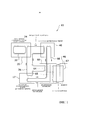
На фиг. 1 представлена первая структурная схема, иллюстрирующая общие компоненты основного варианта осуществления настоящего изобретения.In FIG. 1 is a first block diagram illustrating common components of a main embodiment of the present invention.
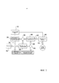
На фиг. 2 представлена вторая структурная схема, иллюстрирующая общие компоненты основного варианта осуществления настоящего изобретения.In FIG. 2 is a second block diagram illustrating common components of a main embodiment of the present invention.
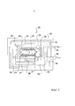
На фиг. 3 представлена структурная схема, иллюстрирующая вид в поперечном сечении примерного теплогенератора для использования с настоящим изобретением.In FIG. 3 is a block diagram illustrating a cross-sectional view of an exemplary heat source for use with the present invention.
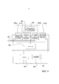
На фиг. 4 представлена структурная схема, иллюстрирующая теплогенератор и системы для преобразования энергии в соответствии с настоящим изобретением.In FIG. 4 is a block diagram illustrating a heat generator and energy conversion systems in accordance with the present invention.
На фиг. 5 представлена структурная схема, иллюстрирующая охлаждающую систему, основанную на абсорбционном холодильнике.In FIG. 5 is a block diagram illustrating a cooling system based on an absorption refrigerator.
На фиг. 6а представлен внутренний вид сверху различных компонентов настоящего изобретения при использовании с электрическим автомобилем.In FIG. 6a is an internal top view of various components of the present invention when used with an electric vehicle.
На фиг. 6b представлен внутренний вид сбоку различных компонентов настоящего изобретения при использовании с электрическим автомобилем.In FIG. 6b is an internal side view of various components of the present invention when used with an electric vehicle.
На фиг. 7 представлен внутренний вид сбоку различных компонентов настоящего изобретения при использовании с электрическим летательным аппаратом.In FIG. 7 is an internal side view of various components of the present invention when used with an electric aircraft.
На фиг. 8 представлена структурная схема, иллюстрирующая альтернативный вариант осуществления настоящего изобретения, который использует турбогенератор двуокиси углерода в сверхкритическом состоянии.In FIG. 8 is a block diagram illustrating an alternative embodiment of the present invention that uses a supercritical carbon dioxide turbogenerator.
Подробное описание изобретенияDETAILED DESCRIPTION OF THE INVENTION
А. ОбзорA. Overview
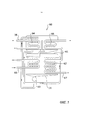
Теперь описательно обратимся к чертежам, на которых аналогичные ссылочные обозначения обозначают аналогичные элементы на нескольких видах, и на фиг. 1-7 иллюстрирована низкоэнергетическая ядерная термоэлектрическая система 10, которая содержит теплогенератор 20 в теплоизоляционной оболочке 30, систему 40 для преобразования энергии, связанную с теплогенератором 20, систему 50 для хранения энергии, связанную с системой 40 для преобразования энергии, охлаждающую систему 60 и центральную управляющую систему 70. Теплогенератор 20 осуществляет реакцию никелевого порошка 23 с водородом в камере 22 реактора для производства теплоты. Затем эту теплоту передают на систему 40 для преобразования энергии для его преобразования в электричество для хранения в системе 50 для хранения энергии. Охлаждающая система 60 обеспечивает охлаждение для различных компонентов настоящего изобретения, а управляющая система 70 регулирует всю его работу.Now, we turn descriptively to the drawings, in which similar reference signs designate similar elements in several views, and in FIG. 1-7, a low-energy nuclear
На фиг. 1 и 2 показаны структурные схемы, иллюстрирующие общую структуру и работу в соответствии с настоящим изобретением. Как видно на фиг. 1, настоящее изобретение содержит теплогенератор 20, имеющий внутренний контур 32 текучей среды, приводимый внутренней гидравлической системой 33. Контур 35 горячей текучей среды передает теплоту от теплогенератора 20 на систему 40 для преобразования энергии, где теплоту преобразуют в энергию, и через охлаждающую систему 60 до возврата к теплогенератору 20. Охлаждающий контур 66 проходит через систему 40 для преобразования энергии, охлаждающую систему 60 и, при необходимости, через систему 17 для кондиционирования воздуха транспортного средства 16. Охлаждающий передаточный контур 67 также соединяет охлаждающую систему 60 с отдельным радиатором 46. Благодаря низкоэнергетической ядерной термоэлектрической генерации теплогенератора 20 настоящее изобретение можно применять для питания транспортного средства эффективным, не наносящим ущерба окружающей среде и экономически эффективным образом.In FIG. 1 and 2 are structural diagrams illustrating the general structure and operation of the present invention. As seen in FIG. 1, the present invention comprises a
В. ТеплогенераторB. Heat generator
Настоящее изобретение использует теплогенератор 20 для производства мощности, подлежащей преобразованию в системе 40 для преобразования энергии и хранению для использования в системе 50 для хранения энергии. Примерный теплогенератор 20 показан на фиг. 3. Следует понимать, что это является только примерным вариантом осуществления, а с настоящим изобретением могут быть использованы различные другие варианты осуществления. Таким образом, конфигурацию примерного теплогенератора 20, показанного на чертежах, не следует толковать, как ограничивающую объем настоящего изобретения.The present invention uses a
С настоящим изобретением могут использовать широкий диапазон теплогенераторов 20. Один такой теплогенератор 20 раскрыт в патентной публикации США №2011/0005506, рассматривающей "Способ и устройство для проведения экзотермической реакции никеля и водорода", содержание которой полностью включено в настоящий документ посредством ссылки. Другой такой теплогенератор 20 раскрыт в патентной публикации США №2011/0249783, рассматривающей "Способ производства энергии и устройство для этого", содержание которой полностью включено в настоящий документ посредством ссылки.A wide range of heat generators can be used with the
Как показано на фиг. 3, теплогенератор 20 в целом содержит камеру 22 реактора, хранящую некоторое количество реагента, такого как никелевый порошок 23, который используют в качестве основного топлива реакции. Резервуар 24 для хранения водорода обеспечен таким образом, что хранящийся водород может быть введен в камеру 22 реактора через водородный инжектор 27. Обеспечен газовый нагнетатель 25, который выполнен с возможностью нагнетания водорода в никелевый порошок 23 для обеспечения реакции и управления ей. Для инициации реакции и управления ею также обеспечены нагреватель 28 и радиочастотный генератор 29, такой как микроволновый генератор 29.As shown in FIG. 3, the
Теплогенератор 20 использует низкоэнергетические ядерные реакции для производства теплоты для использования при производстве энергии. Теплоту производят на основании реакций трансмутации нерадиоактивных изотопов никелевого порошка 23 с газообразным водородом, с получением меди в устойчивом состоянии и нерадиоактивным изотопам меди. Таким образом, настоящее изобретение не требует использования какого-либо радиоактивного топлива и не производит каких-либо радиоактивных побочных продуктов.The
В предпочтительном варианте осуществления теплогенератор 20 заключен в теплоизоляционную оболочку 30, как показано на фиг. 3. Экран 31 высокой плотности заключен в оболочку 30, который окружает различные компоненты теплогенератора 20 для целей безопасности. В предпочтительном варианте осуществления экран 31 состоит из материала, выполненного с возможностью блокировки любого гама-излучения, испущенного при трансмутации, а также любых инертных газов, использованных для целей безопасности.In a preferred embodiment, the
Теплогенератор в целом состоит из камеры 22 реактора. Камера 22 реактора выполнена с возможностью хранения некоторого количества никелевого порошка 23, состоящего из мелких частиц никеля 23. Резервуар 24 для хранения водорода соединен с камерой 22 реактора 22 через инжектор 27, имеющий клапан 26. Резервуар 24 для хранения водорода хранит водородный газ либо в сжатом виде, например, в бутыли, либо в твердом состоянии, например, в виде гидрида магния.The heat generator as a whole consists of a
Газовый нагнетатель 25 управляет давлением и количеством водорода, вводимого через инжектор 27 в камеру 22 реактора с помощью клапана 26. Такая конфигурация обеспечивает возможность регулировки активации и количества реакций трансмутации, тем самым обеспечивая возможность управления количеством тепловой энергии, произведенной посредством реакций в камере 22.The
Нагреватель 28, в предпочтительном варианте осуществления состоящий из электрического нагревателя 28, используют в комбинации с радиочастотным генератором 29 для инициации реакции посредством повышения температуры в камере 22 в течение стартовой фазы генератора и для помощи в регулировке количества производимой теплоты.A
Для специального управления различными компонентами теплогенератора 20 и, таким образом, всей его работы обеспечен управляющий блок 37. В предпочтительном варианте осуществления управляющий блок 37 выполнен с возможностью управления входным потоком водорода через инжектор 27 (например, при помощи управления клапаном 26), а также радиочастотным генератором 29. В предпочтительном варианте осуществления управляющий блок 37 также выполнен с возможностью измерения температуры внутренней части 21 с помощью использования интегрального температурного датчика 38.For special control of the various components of the
Теплоту от теплогенератора 20 передают на систему 40 для преобразования энергии в соответствии с настоящим изобретением с помощью использования внутреннего контура 32 текучей среды с приводом от внутренней гидравлической системы 33, теплообменника 34 и внешнего контура 35 текучей среды с приводом от внешней гидравлической системы 36. Внутренний контур 32 текучей среды состоит из контура охлаждающей текучей среды с замкнутым циклом, полностью заключенного в теплоизоляционную оболочку 30. Внутренний контур 32 текучей среды проходит через оболочку камеры 22 реактора таким образом, что теплоту от тепловых реакций в камере передают на охлаждающую текучую среду в нем.The heat from the
Нагретую охлаждающую текучую среду передают внутри внутреннего контура 32 текучей среды через теплообменник 34, который расположен внутри оболочки 30, как показано на фиг. 3. Теплообменник 34 передает теплоту на внешний контур 35 текучей среды, состоящий из контура 35 горячей текучей среды, для нагрева в нем рабочей текучей среды для преобразования в системе 40 для преобразования энергии. Поскольку все операции теплогенератора 20 работают в закрытых циклах, не производятся никакие выбросы любого сорта, за исключением незначительных уровней гамма излучения, которое того же порядка величины, что и естественный радиационный фон.The heated cooling fluid is transferred inside the
Следует понимать, что в некоторых вариантах осуществления теплогенератор 20 и система 40 для преобразования энергии, которые описаны более подробно ниже, могут быть объединены в единый узел, в котором теплота от теплогенератора 20 прямо передается на систему 40 для преобразования энергии без потребности в какой либо рабочей или охлаждающей текучей среде.It should be understood that in some embodiments, the
С. Система для преобразования энергииC. Energy Conversion System
Настоящее изобретение использует систему 40 для преобразования энергии, чтобы преобразовывать теплоту, созданную теплогенератором 20, в энергию. Система 40 для преобразования энергии может состоять из различных конфигураций, таких как термоэлектрический преобразователь, работающий в закрытом цикле, для преобразования теплоты, произведенной теплогенератором 20, в электричество, которое может храниться в системе 50 для хранения энергии. В соответствии с другими вариантами осуществления система 40 для преобразования энергии может состоять из термокинетического преобразователя, который работает в закрытом цикле, для преобразования теплоты, произведенной теплогенератором 20, во вращательное движение, которое может храниться в системе 50 для хранения энергии.The present invention uses the
Система 40 для преобразования энергии в соответствии с настоящим изобретением в целом будет содержать по меньшей мере один двигатель 41 Стирлинга для производства линейного движения из теплоты, по меньшей мере один поршневой компрессор 42 одинарного действия или вентилятор, увеличивающий давление рабочей текучей среды из линейного движения двигателя 41 Стирлинга, турбину 48, производящую вращательное движение из сжатой текучей среды, и роторный электрический генератор 49, производящий электричество из вращения турбины 48.The
В соответствии с предпочтительным вариантом осуществления, как показано на фиг. 4, система 40 для преобразования энергии состоит из первого двигателя 41а Стирлинга и второго двигателя 41b Стирлинга, которые выполнены в виде динамически сбалансированных и противоположных пар для снижения вибраций и шумов. Двигатели 41(а,b) Стирлинга принимают нагретую рабочую текучую среду от внешнего контура 35 текучей среды теплоизоляционной оболочки 30, который приводится внешней гидравлической системой 36.According to a preferred embodiment, as shown in FIG. 4, the
Первый компрессор 42а соединен с первым двигателем 41а Стирлинга, а второй компрессор 42b соединен со вторым двигателем 41b Стирлинга. В соответствии с предпочтительным вариантом осуществления компрессоры 42 состоят из поршневых компрессоров одинарного действия или вентиляторов, которые связаны с туробгенератором 47, который содержит турбину 48 и роторный генератор 49.The
Теплота от теплогенератора 20, переданная через контур 35 горячей текучей среды, питает каждый из двигателей 41 Стирлинга посредством содержания расширительных цилиндров обоих двигателей при высокой температуре, в то время как охлаждающую текучую среду передают на двигатели 41 через холодную гидравлическую систему 45 для содержания каждого цилиндра сжатия при низкой температуре.The heat from the
Двигатели 41 Стирлинга хорошо известны в области техники, и их различные конфигурации, известные, как эффективные в использовании, могут использоваться с настоящим изобретением. В соответствии с предпочтительным вариантом осуществления двигатель 41 Стирлинга состоит из известного двигателя 41 вытеснительного типа со свободным поршнем, в котором силовой поршень приводит поршневой компрессор 42 одинарного действия. Двигатели 41 Стирлинга, компрессоры 42 и турбогенератор 47 используют одну и ту же рабочую текучую среду, обычно состоящую из газообразного гелия. Гидравлические системы 36, 45 регулируют температуру работы и, таким образом, эффективность преобразования энергии, и управляют ею.Stirling engines 41 are well known in the art, and their various configurations, known to be efficient to use, can be used with the present invention. According to a preferred embodiment, the Stirling engine 41 consists of a known free-piston displacement type motor 41, in which a power piston drives a single-acting reciprocating compressor 42. Stirling engines 41, compressors 42, and a
Радиатор 46 связан с внешней гидравлической системой 36 для удаления всей остальной неиспользованной теплоты наружу электрического транспортного средства. Все операции системы для преобразования энергии работают в закрытом цикле для предотвращения таким образом каких-либо выбросов любого типа.
В отношении системы 40 для преобразования энергии изобретателем были рассмотрены множественные альтернативные варианты осуществления. Например, в соответствии с одним таким альтернативным вариантом осуществления система 40 для преобразования энергии может состоять из двигателя 41 Стирлинга со свободным поршнем, производящим линейное движение из теплоты, и линейный генератор переменного тока, производящий электричество из линейного движения двигателя 41 Стирлинга.With respect to the
В соответствии с другим вариантом осуществления система 40 для преобразования энергии может состоять из термокинетического преобразователя, работающего в закрытом цикле, для преобразования теплоты, произведенной теплогенератором 20, в кинетическую энергию для хранения в системе 50 для накопления энергии. Такая конфигурация будет состоять из двигателя 41 Стирлинга, одного компрессора 42, повышающего давление рабочей текучей среды из линейного движения двигателя 41, и турбины 48, производящей вращательное движение из сжатой текучей среды таким образом, что кинетическая энергия может сохраняться в маховиковой системе 50 для хранения энергии.According to another embodiment, the
В соответствии с еще одним вариантом осуществления система 40 для преобразования энергии может состоять из парового турбогенератора, содержащего испаритель, преобразующий жидкую воду в пар высокого давления, используя теплоту от рабочей текучей среды, турбины 48, производящей вращательное движение из пара высокого давления, роторного электрического генератора 49, производящего электричество из вращения турбины, и конденсатора, использующего охлаждающую текучую среду для преобразования группы высокого давления, выходящей из турбины 48 обратно в жидкую воду для начала цикла обратно в испаритель. В соответствии с альтернативным вариантом осуществления пар и жидкую воду могут заменять на двуокись углерода в сверхкритическом состоянии в качестве рабочей текучей среды, как показано на фиг. 8.According to another embodiment, the
В соответствии с другим альтернативным вариантом система 40 для преобразования энергии может состоять из термоэлектрического преобразователя, состоящего из парового двигателя с использованием вторичной теплоты, работающего по принципу цикла Ренкина, работающего в закрытом цикле, таком как общеизвестный двигатель "с циклом Щолля", который преобразует теплоту во вращательное движение, которое может храниться в системе 50 для хранения энергии или преобразовываться в электричество.According to another alternative, the
В соответствии с другим альтернативным вариантом используют термоэлектрический преобразователь, состоящий из термобатарейного узла, использующего эффект Зеебика или Пельтье для преобразования температурной разницы между нагретой передаточной текучей средой и охлаждающей текучей средой в электрическую разность потенциалов.According to another alternative, a thermoelectric converter is used consisting of a thermopile assembly using the Seebik or Peltier effect to convert the temperature difference between the heated transmission fluid and the cooling fluid into an electric potential difference.
В соответствии с последним альтернативным вариантом используют термоэлектрический преобразователь энергии Джонсона, состоящий из твердотельного теплового двигателя, который основан на фоторазложении и рекомбинации водорода в топливных элементах с использованием приблизительного цикла Эрикссона, тем самым производя электричество из теплоты.According to the latter alternative, a Johnson thermoelectric energy converter is used, consisting of a solid-state heat engine, which is based on photodegradation and hydrogen recombination in fuel cells using an approximate Ericsson cycle, thereby generating electricity from heat.
D. Система для хранения энергииD. Energy storage system
Настоящее изобретение использует систему 50 для хранения энергии для хранения энергии, произведенной посредством системы 40 для преобразования энергии. С настоящим изобретением могут быть использованы различные системы 50 для хранения энергии, включая электрические батареи, маховиковые системы для хранения кинетической энергии или их комбинации.The present invention uses an
В соответствии с предпочтительным вариантом осуществления система 50 для хранения энергии состоит из узла, содержащего электрические батареи, выполненные с возможностью хранения электричества, произведенного системой 40 для преобразования энергии. Рабочую температуру батарей могут отслеживать с помощью термометра и регулировать с помощью системы для температуры батарей, которая использует теплоту от нагретой рабочей текучей среды и охлаждение от охлаждающей жидкости, произведенных теплогенератором 20 и охлаждающей системой 60, соответственно.According to a preferred embodiment, the
E. Охлаждающая системаE. Cooling system
На фиг. 5 иллюстрирован примерный вариант осуществления охлаждающей системы 60 для использования с настоящим изобретением. В предпочтительном варианте осуществления охлаждающая система 60 состоит из абсорбционного холодильника, который используют для производства полезного охлаждения из избыточной теплоты теплогенератора 20 для улучшения эффективности системы 40 для преобразования энергии и для обеспечения источника охлаждения для регулировки температуры системы 50 для хранения энергии и, в некоторых случаях, системы для кондиционирования воздуха для транспортного средства.In FIG. 5 illustrates an exemplary embodiment of a
Охлаждающая система 60 в целом содержит испаритель 61, в котором холодильная текучая среда испаряется в среде низкого парциального давления, тем самым извлекая теплоту из своего окружения и охлаждая охлаждающую текучую среду. Газообразную холодильную текучую среду абсорбируют и растворяют в жидком абсорбирующем растворе внутри абсорбера 62, тем самым снижая ее парциальное давление внутри испарителя 61 и обеспечивая возможность испарения большего количества жидкой холодильной текучей среды.The
Жидкий абсорбирующий раствор передают с помощью насоса 63 на теплообменный бойлер 64, где его нагревают, вызывая испарение растворенной холодильной текучей среды, как показано на фиг. 5. Затем испаренную текучую среду конденсируют с помощью конденсатора 65, используя охлаждающую воду для пополнения подачи жидкой холодильной текучей среды в испаритель. Охлаждающая система 60 использует как охлаждающий контур 66, так и охлаждающий передаточный контур 67 для передачи текучей среды и, таким образом, теплоты и охлаждения в охлаждающую систему 60 и из нее.The liquid absorbent solution is transferred via a
В соответствии с альтернативным вариантом осуществления охлаждающая система 60 может состоять из пассивного или активного водно-воздушного радиатора. В соответствии с указанным активным вариантом осуществления для улучшения охлаждающих характеристик охлаждающей системы 60 могут использовать электрический вентилятор.According to an alternative embodiment, the
В соответствии с другим альтернативным вариантом осуществления охлаждающая система 60 может состоять из пассивного или активного теплоотвода на основании теплообменника, использующего воздух или воду, доступные снаружи электрического транспортного средства, как источник охлаждения.According to another alternative embodiment, the
F. Центральная управляющая системаF. Central Management System
Настоящее изобретение содержит центральную управляющую систему 70 для регулировки всей работы всей системы 10. Управляющая система 70 выполнена с возможностью включения теплогенератора 70, когда запускают транспортное средство, или когда система 50 для хранения находится ниже своей максимальной емкости. Управляющая система 70 также выполнена с возможностью выключения теплогенератора 20, когда система 50 для хранения энергии достигла своей максимальной емкости.The present invention includes a
Управляющая система 70 может состоять из различных компонентов. В соответствии с предпочтительным вариантом осуществления она будет выполнена с возможностью отправки команд на управляющий блок 37 теплогенератора 20 для включения/выключения теплогенератора 20 для регулировки количества производимой теплоты. В соответствии с дополнительным вариантом осуществления она будет выполнена с возможностью управления гидравлическими системами 33, 36, 45 для организации потоков нагретой передаточной текучей среды и охлаждающей текучей среды на всем протяжении настоящего изобретения.The
Управляющая система 70 также будет действовать с возможностью взаимодействия с системами для регулировки температуры, таких как для системы 50 для хранения энергии, для повышения или понижения температуры батарей по требованию. Наконец, управляющая система 70 будет взаимодействовать с системой для кондиционирования воздуха транспортного средства для повышения или понижения температуры воздуха внутри этого транспортного средства.The
G. Транспортные средстваG. Vehicles
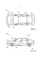
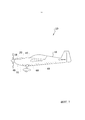
Настоящее изобретение можно использовать с широким диапазоном транспортных средств 16, таких как автобусы, грузовые автомобили, суда, поезда, самолеты, вертолеты, другие летательные аппараты и тому подобное. В предпочтительном варианте осуществления настоящее изобретение выполнено с возможностью использования с электрическим автомобилем 16, что обеспечивает возможность увеличенного рабочего запаса хода в несколько тысяч миль на одну заправку. Вес транспортного средства 16 может быть снижен за счет уменьшения размера и емкости батарей 19, необходимых для достижения требуемого запаса хода, тем самым улучшая маневренность и относительные технические данные этого транспортного средства. На фиг. 6а и 6b иллюстрирован примерный вариант осуществления настоящего изобретения при использовании в автомобиле. На фиг. 7 иллюстрирован примерный вариант осуществления настоящего изобретения при использовании в летательном аппарате.The present invention can be used with a wide range of
Транспортное средство 16 будет сконструировано с возможностью оснащения теплогенератором 20, системой 40 для преобразования энергии, системой 50 для хранения энергии, охлаждающей системой 60 и центральной управляющей системой 70 в пределах площади его грузового пространства. Настоящее изобретение может быть использовано с возможностью приведения электрического двигателя 18 транспортного средства 16 и обеспечения энергии, подлежащей хранению в электрической батарее 19 транспортного средства 16.The
Настоящее изобретение также может быть использовано для увеличения эффективности системы 17 для кондиционирования воздуха транспортного средства 16 и/или регулировки температуры электрических батарей 19 транспортного средства 16. Благодаря использованию избыточной теплоты, созданного посредством теплогенератора 20, в комбинации с дополнительной охлаждающей текучей средой можно регулировать температуру электрических батарей 19 и/или системы 17 для кондиционирования воздуха транспортного средства 16, часто в комбинации с центральной управляющей системой 70. Таким образом, могут быть снижены или полностью исключены существенные недостатки в работе электрических транспортных средств 16.The present invention can also be used to increase the efficiency of the
Н. Работа альтернативного варианта осуществленияH. Operation of an Alternative Embodiment
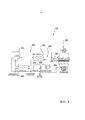
На фиг. 8 иллюстрирован альтернативный вариант осуществления настоящего изобретения, в котором для функциональных возможностей преобразования энергии настоящего изобретения использован турбогенератор 80 двуокиси углерода в сверхкритическом состоянии, работающий по закрытому циклу Брайтона. Цикл Брайтона хорошо известен из уровня техники, как термодинамический цикл, используемый в связи с тепловыми двигателями и газовыми турбинами с закрытым циклом.In FIG. 8 illustrates an alternative embodiment of the present invention in which the supercritical carbon
В соответствии с альтернативным вариантом осуществления настоящего изобретения турбогенератор 80 термически соединен с теплогенератором 20 в соответствии с настоящим изобретением через контур 35, 88 горячей текучей среды, который в комбинации с теплообменником 34, 87 передает теплоту от теплогенератора 20 на турбогенератор 80 для преобразования в энергию.According to an alternative embodiment of the present invention, the
Могут быть использованы различные типы турбогенераторов 80. Предпочтительный вариант осуществления показан на фиг. 8, который содержит насос 81, рекуператор 82, турбину 86 и конденсатор 83, соединенные через один и тот же контур 88 горячей текучей среды, который термически связан через теплообменник 87 с теплогенератором 20 в соответствии с настоящим изобретением. Насос 81 действует с возможностью нагнетания текучей среды в сверхкритическом состоянии через контур 88.Various types of turbo-
Рекуператор 82 используют для предварительного нагрева текучей среды до ее входа в теплообменник 34, 87 с теплогенератором 20. Рекуператор 82 также предварительно охлаждает текучую среду до ее входа в конденсатор 83, который связан через охлаждающий контур 89 с охлаждающим водоснабжением и охлаждающей водоотдачей.The
Редуктор 85 и генератор 84 соединены с турбиной 86 для производства энергии, которую затем могут передавать на систему 50 для хранения энергии, электрический двигатель 18, электрическую батарею 19 и/или как дополнительное питание для теплогенератора 20.A reducer 85 and a generator 84 are connected to a
Если не указано иное, все технические и научные термины, используемые в настоящем документе, имеют то же значение, как и обычно понимаемое специалистом в области техники, к которой это изобретение принадлежит. Хотя в практическом осуществлении или тестировании настоящего изобретения могут быть использованы способы и материалы, аналогичные или эквивалентные описанным в настоящем документе, подходящие способы и материалы были описаны выше. Полное содержание всех публикаций, патентных заявок, патентов и других ссылок, упомянутых в настоящем документе, включено посредством ссылки в той степени, которая допускается действующим законодательством и положениями. В случае противоречий будет регулировать настоящая спецификация, включая определения. Настоящее изобретение может быть воплощено в других конкретных формах без отхода от его сущности или существенных признаков, и, следовательно, требуется рассматривать настоящий вариант осуществления во всех отношениях, как иллюстративный, а не ограничительный. Любые заголовки, использованные в описании, приведены только для удобства и не имеют какого либо юридического или ограничивающего эффекта.Unless otherwise indicated, all technical and scientific terms used herein have the same meaning as commonly understood by one of ordinary skill in the art to which this invention belongs. Although methods and materials similar or equivalent to those described herein can be used in the practice or testing of the present invention, suitable methods and materials have been described above. The full contents of all publications, patent applications, patents, and other references mentioned herein are incorporated by reference to the extent permitted by applicable law and regulations. In case of conflict, this specification, including definitions, will govern. The present invention can be embodied in other specific forms without departing from its essence or essential features, and therefore it is required to consider the present embodiment in all respects as illustrative and not restrictive. Any headings used in the description are for convenience only and do not have any legal or limiting effect.
Claims (42)
Applications Claiming Priority (3)
| Application Number | Priority Date | Filing Date | Title |
|---|---|---|---|
| US13/848,888 | 2013-03-22 | ||
| US13/848,888 US9540960B2 (en) | 2012-03-29 | 2013-03-22 | Low energy nuclear thermoelectric system |
| PCT/EP2014/052961 WO2014146836A2 (en) | 2013-03-22 | 2014-02-14 | Low energy nuclear thermoelectric system |
Publications (2)
| Publication Number | Publication Date |
|---|---|
| RU2015131057A RU2015131057A (en) | 2017-04-28 |
| RU2668383C2 true RU2668383C2 (en) | 2018-09-28 |
Family
ID=50193447
Family Applications (1)
| Application Number | Title | Priority Date | Filing Date |
|---|---|---|---|
| RU2015131057A RU2668383C2 (en) | 2013-03-22 | 2014-02-14 | Low-energy nuclear thermoelectric system |
Country Status (8)
| Country | Link |
|---|---|
| US (1) | US9540960B2 (en) |
| EP (1) | EP2976231A2 (en) |
| JP (1) | JP2016521534A (en) |
| KR (1) | KR102220025B1 (en) |
| CN (1) | CN105050848A (en) |
| CA (1) | CA2901506A1 (en) |
| RU (1) | RU2668383C2 (en) |
| WO (1) | WO2014146836A2 (en) |
Families Citing this family (22)
| Publication number | Priority date | Publication date | Assignee | Title |
|---|---|---|---|---|
| ES2522537T3 (en) * | 2011-01-13 | 2014-11-14 | Sincron S.R.L. | Method and set to convert solar radiation into mechanical energy |
| DE102011122071B4 (en) * | 2011-12-22 | 2013-10-31 | Eads Deutschland Gmbh | Stirling engine with flapping wing for an emission-free aircraft |
| US10475980B2 (en) * | 2012-03-29 | 2019-11-12 | Lenr Cars Sa | Thermoelectric vehicle system |
| US9797309B2 (en) * | 2013-04-09 | 2017-10-24 | David J. Podrog | Hafnium turbine engine and method of operation |
| US20160079783A1 (en) * | 2014-09-11 | 2016-03-17 | Nissan North America, Inc. | Battery charging module for a vehicle |
| US10480084B1 (en) | 2016-03-03 | 2019-11-19 | Marathon Systems, Inc. | Modular cooling chamber for manifold of gaseous electrolysis apparatus with helium permeable element therefor |
| EP3401922A1 (en) * | 2017-05-12 | 2018-11-14 | RIToN Holding Ltd | Heating system |
| US20190019592A1 (en) * | 2017-07-13 | 2019-01-17 | Lenr Cars Sa | Method of Producing Energy from Condensed Hydrogen Clusters |
| RU2749989C2 (en) * | 2017-07-21 | 2021-06-21 | Александр Прокопьевич Зиновьев | Rubber-tyred automobile for off-road transportation of people and goods |
| CN107785092A (en) * | 2017-11-01 | 2018-03-09 | 中国船舶重工集团公司第七〇九研究所 | The charger baby that can persistently use |
| US10876061B2 (en) * | 2017-11-22 | 2020-12-29 | Gaiaca, LLC | Systems and methods for cannabis waste disposal |
| US11318510B2 (en) | 2017-11-22 | 2022-05-03 | Gaiaca, LLC | Systems and methods for cannabis waste disposal |
| CN108983112B (en) * | 2018-04-27 | 2020-02-07 | 西安交通大学 | Small-size nuclear power supply integration test device |
| CN108988739B (en) * | 2018-08-22 | 2020-12-11 | 中国科学院合肥物质科学研究院 | Nuclear reactor combined wind power and solar photovoltaic grid-connected power generation system |
| CN109677639B (en) * | 2018-12-30 | 2020-08-04 | 上海空间推进研究所 | Space high-power nuclear power system based on closed Brayton cycle |
| US20210110938A1 (en) * | 2019-10-11 | 2021-04-15 | James F. Loan | Method and apparatus for controlling a low energy nuclear reaction |
| WO2021162822A2 (en) * | 2020-01-14 | 2021-08-19 | Quantum Industrial Development Corp. | Stirling powered unmanned aerial vehicle |
| CA3165403A1 (en) * | 2020-02-07 | 2021-08-12 | Christopher Morrison | Chargeable atomic battery with pre-activation encapsulation manufacturing |
| CN113320378B (en) * | 2021-06-29 | 2022-08-09 | 重庆金康赛力斯新能源汽车设计院有限公司 | Efficient integrated engine thermal management system and vehicle |
| CN113320377B (en) * | 2021-06-29 | 2022-11-25 | 重庆金康赛力斯新能源汽车设计院有限公司 | Whole vehicle thermal management system capable of recycling energy and vehicle |
| CN113539541A (en) * | 2021-07-19 | 2021-10-22 | 安徽中科超安科技有限公司 | Nuclear power generation power supply system and nuclear power automobile with same |
| US11846273B1 (en) * | 2022-08-17 | 2023-12-19 | Venus Aerospace Corp | Reactor rocket engine |
Citations (3)
| Publication number | Priority date | Publication date | Assignee | Title |
|---|---|---|---|---|
| RU2195717C1 (en) * | 2001-08-23 | 2002-12-27 | Киркинский Виталий Алексеевич | Energy generating device |
| US20090283007A1 (en) * | 2008-05-14 | 2009-11-19 | William Gregory Taylor | Nuclear locomotive |
| US20110005506A1 (en) * | 2008-04-09 | 2011-01-13 | Andrea Rossi | Method and apparatus for carrying out nickel and hydrogen exothermal reaction |
Family Cites Families (89)
| Publication number | Priority date | Publication date | Assignee | Title |
|---|---|---|---|---|
| US4072186A (en) | 1976-04-05 | 1978-02-07 | Ford Motor Company | Dual function heater core |
| DE3434532C1 (en) | 1984-09-20 | 1986-02-13 | Messerschmitt-Bölkow-Blohm GmbH, 8012 Ottobrunn | Power supply system for a motor vehicle |
| JPH01294946A (en) * | 1988-05-20 | 1989-11-28 | Kubota Ltd | Waste heat utilizing device for engine |
| EP0698893A3 (en) | 1989-03-13 | 1996-03-06 | University Of Utah Research Foundation | Method and apparatus for power generation |
| BE1002780A7 (en) | 1989-04-21 | 1991-06-04 | Den Bogaert Joannes Van | Nuclear fusion |
| JPH02310494A (en) | 1989-05-26 | 1990-12-26 | Matsushita Electric Ind Co Ltd | Low-temperature nuclear fusion device |
| JPH032689A (en) * | 1989-05-31 | 1991-01-09 | Hitachi Ltd | Low-temperature nuclear fusion energy system |
| BE1002781A6 (en) | 1989-06-05 | 1991-06-04 | Van Den Bogaert Joannes | Method for the production of energy by means of nuclear fusion |
| JPH03205301A (en) | 1989-08-04 | 1991-09-06 | Canon Inc | Method for storing hydrogen, apparatus for nuclear fusion at ordinary temperature utilizing the same method and method for generating heat energy |
| BE1003296A6 (en) | 1990-01-10 | 1992-02-18 | Van Den Bogaert Joannes | Nuclear fusion |
| JP2773417B2 (en) | 1990-09-28 | 1998-07-09 | アイシン精機株式会社 | Free piston stirling engine |
| US5172784A (en) | 1991-04-19 | 1992-12-22 | Varela Jr Arthur A | Hybrid electric propulsion system |
| JPH0675072A (en) | 1991-06-24 | 1994-03-18 | Aisin Aw Co Ltd | P/f effect device |
| AU2316292A (en) | 1991-06-27 | 1993-01-25 | Electric Power Research Institute, Inc. | Apparatus for producing heat from deuterated film-coated palladium |
| DE4129330A1 (en) | 1991-07-12 | 1993-01-14 | Campobasso Andreas P | Hydrogen@ prodn. in vehicle using stirling engine - to convert IC engine waste heat into electrical energy for water electrolyser |
| DE4132939A1 (en) | 1991-10-04 | 1993-04-08 | Bayerische Motoren Werke Ag | Air-conditioning unit for electric vehicle passenger space - uses stirling heat pump with reversible drive allowing cooling or heating operations |
| EP0658268A1 (en) | 1992-02-24 | 1995-06-21 | Eneco, Inc. | Method and apparatus for alkali-hydrogen fusion power generation |
| JPH05256994A (en) * | 1992-03-13 | 1993-10-08 | Mitsubishi Heavy Ind Ltd | Nuclear power generator |
| JPH0618683A (en) | 1992-07-03 | 1994-01-28 | Doke Masaaki | Cylinder plating type vibrating electrode apparatus for normal temperature nuclear fusion |
| JPH06137699A (en) | 1992-10-27 | 1994-05-20 | Toyota Autom Loom Works Ltd | Air conditioner for vehicle |
| WO1994028197A2 (en) | 1993-05-25 | 1994-12-08 | Eneco, Inc. | Hydrogen activated heat generation apparatus |
| IT1282858B1 (en) | 1994-01-27 | 1998-04-01 | Francesco Piantelli | THERMOFUSER ENERGY GENERATOR WITH FASEC EFFECT: ANARMONIC FUSION STIMULATED WITH HEAT EMISSION. |
| JPH07279758A (en) * | 1994-04-13 | 1995-10-27 | Daikin Ind Ltd | Co-generation device |
| DE19732307A1 (en) | 1996-08-22 | 1998-02-26 | Volkswagen Ag | Auxiliary drive system for road vehicle |
| US5775273A (en) * | 1997-07-01 | 1998-07-07 | Sunpower, Inc. | Free piston internal combustion engine |
| JP2001130268A (en) * | 1999-11-09 | 2001-05-15 | Denso Corp | Forced cooling device of battery for electric car |
| US7469760B2 (en) | 2000-03-02 | 2008-12-30 | Deka Products Limited Partnership | Hybrid electric vehicles using a stirling engine |
| DE10013080A1 (en) | 2000-03-17 | 2001-09-20 | Still Gmbh | Drive system for mobile electrically driven machine, especially industrial truck, has drive machine designed as Stirling engine, traction battery provided and electrical drive motor(s) supplied by generator and/or traction battery |
| US6543229B2 (en) | 2000-06-14 | 2003-04-08 | Stm Power, Inc. | Exhaust gas alternator system |
| AU2000278569A1 (en) * | 2000-10-03 | 2002-04-15 | Hsiang-Wei Cheng | Cold fusion with a pilot for self generating neutron and beta-particle |
| RU2280925C2 (en) * | 2000-10-30 | 2006-07-27 | Квестэйр Текнолоджиз Инк. | Separating gases of high energy efficiency for fuel cells |
| DE10054022A1 (en) | 2000-11-01 | 2002-05-08 | Bayerische Motoren Werke Ag | Method for operating a heat engine |
| DE10243178B4 (en) | 2002-09-18 | 2004-08-05 | Daimlerchrysler Ag | Device for supplying an air conditioning unit and electrical consumers in a vehicle with energy |
| US20060153752A1 (en) | 2002-10-11 | 2006-07-13 | Yoshiaki Arata | Hydrogen condensate and method of generating heat therewith |
| JP4248303B2 (en) | 2003-05-09 | 2009-04-02 | 本田技研工業株式会社 | Power unit comprising a combustion engine and a Stirling engine |
| EP2264715A2 (en) | 2003-08-12 | 2010-12-22 | Energetics Technologies, LLC | Electrolytic cell thermal power generator and method |
| US8094771B2 (en) * | 2003-11-21 | 2012-01-10 | Global Technologies, Inc. | Nuclear voltaic cell |
| FR2874975B1 (en) * | 2004-09-07 | 2008-12-26 | Philippe Marc Montesinos | PRODUCTION OF LOW ENERGY SOLAR ELECTRICITY |
| US7798204B2 (en) | 2004-09-14 | 2010-09-21 | Cyclone Power Technologies, Inc. | Centrifugal condenser |
| US20070256415A1 (en) | 2004-09-14 | 2007-11-08 | Cyclone Technologies, Lllp | Clearance volume valves in a heat regenerative engine |
| US7080512B2 (en) | 2004-09-14 | 2006-07-25 | Cyclone Technologies Lllp | Heat regenerative engine |
| US7856823B2 (en) | 2004-09-14 | 2010-12-28 | Cyclone Power Technologies, Inc. | Pre-heater coil in a heat regenerative engine |
| US7730873B2 (en) | 2004-09-14 | 2010-06-08 | Cyclone Power Technologies, Inc. | Valve controlled throttle mechanism in a heat regenerative engine |
| US7784280B2 (en) | 2004-09-14 | 2010-08-31 | Cyclone Power Technologies, Inc. | Engine reversing and timing control mechanism in a heat regenerative engine |
| US20070261681A1 (en) | 2004-09-14 | 2007-11-15 | Cyclone Technologies, Lllp | Engine shrouding with air to air heat exchanger |
| US20080289335A1 (en) * | 2004-12-24 | 2008-11-27 | Kenneth William Patterson Drysdale | Methods and Apparatus for Power Generation |
| JP2009509130A (en) | 2005-09-07 | 2009-03-05 | プーラーチョー アーゲー | Generation method of thermal energy |
| EP1934987A4 (en) | 2005-09-09 | 2011-12-07 | Lewis G Larsen | Apparatus and method for absorption of incident gamma radiation and its conversion to outgoing radiation at less penetrating, lower energies and frequencies |
| US7407382B2 (en) | 2005-09-13 | 2008-08-05 | Cyclone Power Technologies, Inc. | Steam generator in a heat regenerative engine |
| US20070056287A1 (en) | 2005-09-13 | 2007-03-15 | Cyclone Technologies Lllp | Splitter valve in a heat regenerative engine |
| US20070206715A1 (en) | 2005-12-29 | 2007-09-06 | Profusion Energy, Inc. | Energy generation apparatus and method |
| JP4724848B2 (en) * | 2006-04-21 | 2011-07-13 | 独立行政法人 日本原子力研究開発機構 | Combined Brayton cycle power generation system using nuclear heat |
| ES2299348B1 (en) * | 2006-05-11 | 2009-02-01 | Alset Technology Llc | CONTROLLED NUCLEAR FUSION PROCESS. |
| US8624636B2 (en) | 2006-05-22 | 2014-01-07 | Brillouin Energy Corp. | Drive circuit and method for semiconductor devices |
| US20070268045A1 (en) | 2006-05-22 | 2007-11-22 | Profusion Energy, Inc. | Drive Circuit And Method For Semiconductor Devices |
| US20080047272A1 (en) | 2006-08-28 | 2008-02-28 | Harry Schoell | Heat regenerative mini-turbine generator |
| CN101187329A (en) * | 2006-11-17 | 2008-05-28 | 林耀章 | Device for producing new energy using internal combustion engine waste heat energy conversion |
| US8419919B1 (en) | 2007-03-14 | 2013-04-16 | Jwk International Corporation | System and method for generating particles |
| US8603405B2 (en) | 2007-03-29 | 2013-12-10 | Npl Associates, Inc. | Power units based on dislocation site techniques |
| US8526560B2 (en) | 2007-03-29 | 2013-09-03 | Npl Associates, Inc. | Method of using deuterium-cluster foils for an intense pulsed neutron source |
| US8227020B1 (en) | 2007-03-29 | 2012-07-24 | Npl Associates, Inc. | Dislocation site formation techniques |
| US8440165B2 (en) | 2007-03-29 | 2013-05-14 | Npl Associates, Inc. | Dislocation site density techniques |
| US20090090573A1 (en) * | 2007-10-03 | 2009-04-09 | Boone Daniel J | Hybrid electric vehicle and towable trailer that uses renewable solid fuel |
| US8191663B2 (en) | 2007-12-07 | 2012-06-05 | Boncodin Franz B | Radioisotope powered engineless vehicle |
| DE102008007159A1 (en) | 2008-02-01 | 2009-07-09 | Daimler Ag | Drive unit i.e. hybrid drive, for vehicle i.e. road vehicle, has stirling engine and generator forming integral stirling unit with generator section in which kinetic energy is converted into electricity |
| US20090277152A1 (en) * | 2008-05-07 | 2009-11-12 | Ronald Steven Sutherland | Quasi-isobaric heat engine |
| WO2010033927A1 (en) | 2008-09-22 | 2010-03-25 | Richard Westfall | Radioisotope thermal generator |
| US7992386B2 (en) | 2008-11-03 | 2011-08-09 | Cyclone Power Technologies, Inc. | Waste heat engine |
| IT1392217B1 (en) | 2008-11-24 | 2012-02-22 | Ghidini | METHOD TO PRODUCE ENERGY AND GENERATOR THAT ACTIVATE THIS METHOD |
| DE102009005852A1 (en) * | 2009-01-23 | 2010-07-29 | Li-Tec Battery Gmbh | Temperate battery system |
| DE102009007231A1 (en) * | 2009-02-03 | 2010-08-12 | Siemens Aktiengesellschaft | Vehicle, in particular motor vehicle |
| JP5394101B2 (en) * | 2009-03-10 | 2014-01-22 | 白川 利久 | Fuel-filled jet crash-capable nuclear ship |
| US20110314805A1 (en) * | 2009-03-12 | 2011-12-29 | Seale Joseph B | Heat engine with regenerator and timed gas exchange |
| US20100283262A1 (en) * | 2009-05-11 | 2010-11-11 | Caterpillar Inc. | Energy Recovery And Cooling System For A Hybrid Machine |
| US8508057B2 (en) | 2009-08-03 | 2013-08-13 | David J. Schulte | Power generator |
| US20120122017A1 (en) * | 2009-08-07 | 2012-05-17 | Mills Randell L | Heterogeneous hydrogen-catalyst power system |
| US8794002B2 (en) * | 2009-09-17 | 2014-08-05 | Echogen Power Systems | Thermal energy conversion method |
| JP2011116234A (en) * | 2009-12-03 | 2011-06-16 | Toyota Industries Corp | Air-conditioning system for moving body |
| US8303865B1 (en) | 2009-12-15 | 2012-11-06 | Brown-Cravens-Taylor | Enhanced alpha particle emitter |
| EP2545192A1 (en) * | 2010-03-10 | 2013-01-16 | BHP Billiton Aluminium Technologies Limited | Heat recovery system for pyrometallurgical vessel using thermoelectric/thermomagnetic devices |
| US20120159951A1 (en) * | 2010-12-24 | 2012-06-28 | Avery Maurice C | Vehicle Propulsion System |
| TWI468629B (en) * | 2010-12-30 | 2015-01-11 | Joy Ride Technology Co Ltd | Air Energy Energy Saving Air Conditioning Power Generation System |
| ITPI20110046A1 (en) | 2011-04-26 | 2012-10-27 | Chellini Fabio | METHOD AND SYSTEM TO GENERATE ENERGY BY MEANS OF NUCLEAR REACTIONS OF HYDROGEN ADSORBED BY ORBITAL CATCH FROM A CRYSTALLINE NANOSTRUCTURE OF A METAL |
| JP2012230069A (en) * | 2011-04-27 | 2012-11-22 | Hitachi-Ge Nuclear Energy Ltd | Auxiliary power supply of nuclear installation |
| US9115913B1 (en) | 2012-03-14 | 2015-08-25 | Leonardo Corporation | Fluid heater |
| WO2013170244A2 (en) * | 2012-05-11 | 2013-11-14 | Borealis Technical Limited | Method and system for high efficiency electricity generation using low energy thermal heat generation and thermionic devices |
| CN105492839A (en) | 2013-05-02 | 2016-04-13 | 工业热有限公司 | Devices and methods for heat generation |
| US9181866B2 (en) * | 2013-06-21 | 2015-11-10 | Caterpillar Inc. | Energy recovery and cooling system for hybrid machine powertrain |
| TW201615328A (en) | 2014-10-21 | 2016-05-01 | Sportsman Corp | Holding clamp |
-
2013
- 2013-03-22 US US13/848,888 patent/US9540960B2/en active Active
-
2014
- 2014-02-14 WO PCT/EP2014/052961 patent/WO2014146836A2/en active Application Filing
- 2014-02-14 CA CA2901506A patent/CA2901506A1/en not_active Abandoned
- 2014-02-14 RU RU2015131057A patent/RU2668383C2/en active
- 2014-02-14 JP JP2016503581A patent/JP2016521534A/en active Pending
- 2014-02-14 EP EP14707669.9A patent/EP2976231A2/en not_active Ceased
- 2014-02-14 KR KR1020157029434A patent/KR102220025B1/en active IP Right Grant
- 2014-02-14 CN CN201480017039.2A patent/CN105050848A/en active Pending
Patent Citations (3)
| Publication number | Priority date | Publication date | Assignee | Title |
|---|---|---|---|---|
| RU2195717C1 (en) * | 2001-08-23 | 2002-12-27 | Киркинский Виталий Алексеевич | Energy generating device |
| US20110005506A1 (en) * | 2008-04-09 | 2011-01-13 | Andrea Rossi | Method and apparatus for carrying out nickel and hydrogen exothermal reaction |
| US20090283007A1 (en) * | 2008-05-14 | 2009-11-19 | William Gregory Taylor | Nuclear locomotive |
Also Published As
| Publication number | Publication date |
|---|---|
| EP2976231A2 (en) | 2016-01-27 |
| US9540960B2 (en) | 2017-01-10 |
| KR20150135362A (en) | 2015-12-02 |
| JP2016521534A (en) | 2016-07-21 |
| CN105050848A (en) | 2015-11-11 |
| US20130263597A1 (en) | 2013-10-10 |
| BR112015023919A2 (en) | 2017-07-18 |
| CA2901506A1 (en) | 2014-09-25 |
| WO2014146836A3 (en) | 2015-03-26 |
| WO2014146836A2 (en) | 2014-09-25 |
| KR102220025B1 (en) | 2021-02-25 |
| RU2015131057A (en) | 2017-04-28 |
Similar Documents
| Publication | Publication Date | Title |
|---|---|---|
| RU2668383C2 (en) | Low-energy nuclear thermoelectric system | |
| US7964787B2 (en) | Hybrid solar power generator | |
| JP6179984B2 (en) | Thermal energy storage device | |
| US8397504B2 (en) | Method and apparatus to recover and convert waste heat to mechanical energy | |
| CN101576024B (en) | Heat returning closed cooling recirculation system of Brighton scramjet | |
| US10475980B2 (en) | Thermoelectric vehicle system | |
| JP2016521534A5 (en) | ||
| CN112880451A (en) | CO based on supplemental external energy2Gas-liquid phase change energy storage device and method | |
| CN112985142A (en) | Heat energy conversion mechanical energy storage device based on carbon dioxide gas-liquid phase change | |
| CN115638566A (en) | Cogeneration system for providing heating and electrical energy to an enclosure | |
| US10294891B2 (en) | Energy collector system applicable to combustion engines | |
| CN102434257B (en) | Power generation device using waste heat of engines of vehicles and ships | |
| JP5312644B1 (en) | Air conditioning power generation system | |
| CN104392750B (en) | Low temperature nuclear reactor and the onboard power systems based on low temperature nuclear reactor | |
| US20120153874A1 (en) | Assembly and method for supplying energy to motorised vehicles | |
| JP2003184650A (en) | External combustion engine driven by heat pump | |
| JP2015034544A (en) | Energy system using external combustion engine | |
| CN210622879U (en) | Single-tank closed type circulating energy storage power generation system | |
| JP2012225313A (en) | Device using constant volume heater | |
| BR112015023919B1 (en) | ELECTRIC CAR, LOW ENERGY NUCLEAR THERMAL SYSTEM AND VEHICLE | |
| RU2379527C1 (en) | Self-contained combined power plant | |
| JP2024516490A (en) | Motor vehicle efficiency and comfort systems | |
| CN114001270A (en) | Water-gas-heat comprehensive energy storage system and method | |
| CN117514386A (en) | Carbon dioxide energy storage subsystem and flue gas waste heat utilization system | |
| JP2016100957A (en) | Power system using external combustion engine |