RU2655294C2 - Catheter with serially connected sensing structures and methods of calibration and detection - Google Patents
Catheter with serially connected sensing structures and methods of calibration and detection Download PDFInfo
- Publication number
- RU2655294C2 RU2655294C2 RU2013158764A RU2013158764A RU2655294C2 RU 2655294 C2 RU2655294 C2 RU 2655294C2 RU 2013158764 A RU2013158764 A RU 2013158764A RU 2013158764 A RU2013158764 A RU 2013158764A RU 2655294 C2 RU2655294 C2 RU 2655294C2
- Authority
- RU
- Russia
- Prior art keywords
- catheter
- pressure
- magnetic field
- distal
- signals
- Prior art date
Links
Images


Classifications
-
- A—HUMAN NECESSITIES
- A61—MEDICAL OR VETERINARY SCIENCE; HYGIENE
- A61M—DEVICES FOR INTRODUCING MEDIA INTO, OR ONTO, THE BODY; DEVICES FOR TRANSDUCING BODY MEDIA OR FOR TAKING MEDIA FROM THE BODY; DEVICES FOR PRODUCING OR ENDING SLEEP OR STUPOR
- A61M25/00—Catheters; Hollow probes
- A61M25/01—Introducing, guiding, advancing, emplacing or holding catheters
- A61M25/0105—Steering means as part of the catheter or advancing means; Markers for positioning
- A61M25/0127—Magnetic means; Magnetic markers
-
- A—HUMAN NECESSITIES
- A61—MEDICAL OR VETERINARY SCIENCE; HYGIENE
- A61B—DIAGNOSIS; SURGERY; IDENTIFICATION
- A61B18/00—Surgical instruments, devices or methods for transferring non-mechanical forms of energy to or from the body
- A61B18/04—Surgical instruments, devices or methods for transferring non-mechanical forms of energy to or from the body by heating
- A61B18/12—Surgical instruments, devices or methods for transferring non-mechanical forms of energy to or from the body by heating by passing a current through the tissue to be heated, e.g. high-frequency current
- A61B18/1206—Generators therefor
-
- A—HUMAN NECESSITIES
- A61—MEDICAL OR VETERINARY SCIENCE; HYGIENE
- A61B—DIAGNOSIS; SURGERY; IDENTIFICATION
- A61B18/00—Surgical instruments, devices or methods for transferring non-mechanical forms of energy to or from the body
- A61B18/04—Surgical instruments, devices or methods for transferring non-mechanical forms of energy to or from the body by heating
- A61B18/12—Surgical instruments, devices or methods for transferring non-mechanical forms of energy to or from the body by heating by passing a current through the tissue to be heated, e.g. high-frequency current
- A61B18/14—Probes or electrodes therefor
- A61B18/1492—Probes or electrodes therefor having a flexible, catheter-like structure, e.g. for heart ablation
-
- A—HUMAN NECESSITIES
- A61—MEDICAL OR VETERINARY SCIENCE; HYGIENE
- A61B—DIAGNOSIS; SURGERY; IDENTIFICATION
- A61B5/00—Measuring for diagnostic purposes; Identification of persons
- A61B5/05—Detecting, measuring or recording for diagnosis by means of electric currents or magnetic fields; Measuring using microwaves or radio waves
-
- A—HUMAN NECESSITIES
- A61—MEDICAL OR VETERINARY SCIENCE; HYGIENE
- A61B—DIAGNOSIS; SURGERY; IDENTIFICATION
- A61B5/00—Measuring for diagnostic purposes; Identification of persons
- A61B5/06—Devices, other than using radiation, for detecting or locating foreign bodies ; determining position of probes within or on the body of the patient
- A61B5/061—Determining position of a probe within the body employing means separate from the probe, e.g. sensing internal probe position employing impedance electrodes on the surface of the body
- A61B5/062—Determining position of a probe within the body employing means separate from the probe, e.g. sensing internal probe position employing impedance electrodes on the surface of the body using magnetic field
-
- A—HUMAN NECESSITIES
- A61—MEDICAL OR VETERINARY SCIENCE; HYGIENE
- A61B—DIAGNOSIS; SURGERY; IDENTIFICATION
- A61B5/00—Measuring for diagnostic purposes; Identification of persons
- A61B5/06—Devices, other than using radiation, for detecting or locating foreign bodies ; determining position of probes within or on the body of the patient
- A61B5/065—Determining position of the probe employing exclusively positioning means located on or in the probe, e.g. using position sensors arranged on the probe
-
- A—HUMAN NECESSITIES
- A61—MEDICAL OR VETERINARY SCIENCE; HYGIENE
- A61B—DIAGNOSIS; SURGERY; IDENTIFICATION
- A61B5/00—Measuring for diagnostic purposes; Identification of persons
- A61B5/68—Arrangements of detecting, measuring or recording means, e.g. sensors, in relation to patient
- A61B5/6846—Arrangements of detecting, measuring or recording means, e.g. sensors, in relation to patient specially adapted to be brought in contact with an internal body part, i.e. invasive
- A61B5/6847—Arrangements of detecting, measuring or recording means, e.g. sensors, in relation to patient specially adapted to be brought in contact with an internal body part, i.e. invasive mounted on an invasive device
- A61B5/6852—Catheters
-
- A—HUMAN NECESSITIES
- A61—MEDICAL OR VETERINARY SCIENCE; HYGIENE
- A61B—DIAGNOSIS; SURGERY; IDENTIFICATION
- A61B5/00—Measuring for diagnostic purposes; Identification of persons
- A61B5/72—Signal processing specially adapted for physiological signals or for diagnostic purposes
-
- A—HUMAN NECESSITIES
- A61—MEDICAL OR VETERINARY SCIENCE; HYGIENE
- A61M—DEVICES FOR INTRODUCING MEDIA INTO, OR ONTO, THE BODY; DEVICES FOR TRANSDUCING BODY MEDIA OR FOR TAKING MEDIA FROM THE BODY; DEVICES FOR PRODUCING OR ENDING SLEEP OR STUPOR
- A61M25/00—Catheters; Hollow probes
- A61M25/01—Introducing, guiding, advancing, emplacing or holding catheters
-
- A—HUMAN NECESSITIES
- A61—MEDICAL OR VETERINARY SCIENCE; HYGIENE
- A61B—DIAGNOSIS; SURGERY; IDENTIFICATION
- A61B18/00—Surgical instruments, devices or methods for transferring non-mechanical forms of energy to or from the body
- A61B2018/00315—Surgical instruments, devices or methods for transferring non-mechanical forms of energy to or from the body for treatment of particular body parts
- A61B2018/00345—Vascular system
- A61B2018/00351—Heart
- A61B2018/00357—Endocardium
-
- A—HUMAN NECESSITIES
- A61—MEDICAL OR VETERINARY SCIENCE; HYGIENE
- A61B—DIAGNOSIS; SURGERY; IDENTIFICATION
- A61B18/00—Surgical instruments, devices or methods for transferring non-mechanical forms of energy to or from the body
- A61B2018/00571—Surgical instruments, devices or methods for transferring non-mechanical forms of energy to or from the body for achieving a particular surgical effect
- A61B2018/00577—Ablation
-
- A—HUMAN NECESSITIES
- A61—MEDICAL OR VETERINARY SCIENCE; HYGIENE
- A61B—DIAGNOSIS; SURGERY; IDENTIFICATION
- A61B34/00—Computer-aided surgery; Manipulators or robots specially adapted for use in surgery
- A61B34/20—Surgical navigation systems; Devices for tracking or guiding surgical instruments, e.g. for frameless stereotaxis
- A61B2034/2046—Tracking techniques
- A61B2034/2051—Electromagnetic tracking systems
-
- A—HUMAN NECESSITIES
- A61—MEDICAL OR VETERINARY SCIENCE; HYGIENE
- A61B—DIAGNOSIS; SURGERY; IDENTIFICATION
- A61B90/00—Instruments, implements or accessories specially adapted for surgery or diagnosis and not covered by any of the groups A61B1/00 - A61B50/00, e.g. for luxation treatment or for protecting wound edges
- A61B90/06—Measuring instruments not otherwise provided for
- A61B2090/064—Measuring instruments not otherwise provided for for measuring force, pressure or mechanical tension
- A61B2090/065—Measuring instruments not otherwise provided for for measuring force, pressure or mechanical tension for measuring contact or contact pressure
-
- A—HUMAN NECESSITIES
- A61—MEDICAL OR VETERINARY SCIENCE; HYGIENE
- A61B—DIAGNOSIS; SURGERY; IDENTIFICATION
- A61B5/00—Measuring for diagnostic purposes; Identification of persons
- A61B5/68—Arrangements of detecting, measuring or recording means, e.g. sensors, in relation to patient
- A61B5/6846—Arrangements of detecting, measuring or recording means, e.g. sensors, in relation to patient specially adapted to be brought in contact with an internal body part, i.e. invasive
- A61B5/6885—Monitoring or controlling sensor contact pressure
-
- A—HUMAN NECESSITIES
- A61—MEDICAL OR VETERINARY SCIENCE; HYGIENE
- A61M—DEVICES FOR INTRODUCING MEDIA INTO, OR ONTO, THE BODY; DEVICES FOR TRANSDUCING BODY MEDIA OR FOR TAKING MEDIA FROM THE BODY; DEVICES FOR PRODUCING OR ENDING SLEEP OR STUPOR
- A61M25/00—Catheters; Hollow probes
- A61M2025/0001—Catheters; Hollow probes for pressure measurement
- A61M2025/0002—Catheters; Hollow probes for pressure measurement with a pressure sensor at the distal end
Landscapes
- Health & Medical Sciences (AREA)
- Life Sciences & Earth Sciences (AREA)
- Engineering & Computer Science (AREA)
- Surgery (AREA)
- Public Health (AREA)
- Biomedical Technology (AREA)
- Heart & Thoracic Surgery (AREA)
- Animal Behavior & Ethology (AREA)
- Veterinary Medicine (AREA)
- General Health & Medical Sciences (AREA)
- Physics & Mathematics (AREA)
- Medical Informatics (AREA)
- Molecular Biology (AREA)
- Biophysics (AREA)
- Pathology (AREA)
- Nuclear Medicine, Radiotherapy & Molecular Imaging (AREA)
- Plasma & Fusion (AREA)
- Otolaryngology (AREA)
- Human Computer Interaction (AREA)
- Hematology (AREA)
- Pulmonology (AREA)
- Anesthesiology (AREA)
- Signal Processing (AREA)
- Computer Vision & Pattern Recognition (AREA)
- Physiology (AREA)
- Psychiatry (AREA)
- Cardiology (AREA)
- Artificial Intelligence (AREA)
- Radiology & Medical Imaging (AREA)
- Media Introduction/Drainage Providing Device (AREA)
- Measuring And Recording Apparatus For Diagnosis (AREA)
- Surgical Instruments (AREA)
- Measurement And Recording Of Electrical Phenomena And Electrical Characteristics Of The Living Body (AREA)
- Measurement Of Length, Angles, Or The Like Using Electric Or Magnetic Means (AREA)
Abstract
Description
ОБЛАСТЬ ТЕХНИКИ, К КОТОРОЙ ОТНОСИТСЯ ИЗОБРЕТЕНИЕFIELD OF THE INVENTION
Настоящее изобретение относится к катетерам, а именно к катетерам с возможностями определения локализации или ориентации и давления.The present invention relates to catheters, and in particular to catheters with the ability to determine localization or orientation and pressure.
ПРЕДПОСЫЛКИ СОЗДАНИЯ ИЗОБРЕТЕНИЯBACKGROUND OF THE INVENTION
В некоторых диагностических и лечебных методиках катетер вводится в полость сердца и приводится в контакт с внутренней стенкой сердца. Например, при внутрисердечной радиочастотной (РЧ) абляции катетер с электродом в его периферическом наконечнике через сосудистую систему пациента вводится в камеру сердца. Электрод приводится в контакт с участком (участками) эндокарда и распознает электрическую активность внутри камеры сердца. Кроме того, через катетер к электроду может быть приложена РЧ-энергия с целью локального удаления части ткани сердца.In some diagnostic and therapeutic methods, a catheter is inserted into the heart cavity and brought into contact with the inner wall of the heart. For example, in intracardiac radiofrequency (RF) ablation, a catheter with an electrode in its peripheral tip is inserted through the patient's vascular system into the heart chamber. The electrode is brought into contact with the site (s) of the endocardium and recognizes the electrical activity inside the heart chamber. In addition, RF energy can be applied to the electrode through a catheter to locally remove part of the heart tissue.
Катетеры для выполнения картирования и абляции, как правило, несут один или более магнитных датчиков положения, генерирующих импульсы, которые используются для выявления координат положения дистального сегмента катетера. С этой целью в непосредственной близости от пациента приводятся в действие генераторы магнитного поля с целью создания магнитных полей. Как правило, генераторы поля представляют собой катушки, которые располагают в заданных положениях снаружи от пациента ниже его туловища. Эти катушки создают магнитные поля, которые воспринимаются магнитным датчиком положения катетера. Датчик генерирует электрические импульсы, которые поступают на импульсный процессор по кабелям, идущим через катетер.Catheters for performing mapping and ablation, as a rule, carry one or more magnetic position sensors generating pulses, which are used to determine the position coordinates of the distal segment of the catheter. To this end, in the immediate vicinity of the patient, magnetic field generators are driven to create magnetic fields. As a rule, field generators are coils that are placed in predetermined positions outside the patient below his torso. These coils create magnetic fields that are sensed by a magnetic catheter position sensor. The sensor generates electrical impulses that are supplied to the pulse processor through cables through the catheter.
Для выполнения необходимой диагностической процедуры и достижения лечебного эффекта необходим надлежащий контакт электрода с эндокардом. Однако чрезмерное надавливание может вызвать нежелательное повреждение ткани сердца и даже перфорацию стенки сердца. Для определения давления катетер, как правило, снабжен миниатюрной передающей катушкой и тремя измерительными катушками, расположенными на противоположных участках гибко присоединенного дистального сегмента наконечника. Передающая катушка ориентирована вдоль продольной оси катетера, три измерительные катушки также ориентированы вдоль продольной оси, но размещены на равном расстоянии от передающей катушки и в равноудаленных положениях радиально вокруг продольной оси катетера. Миниатюрная передающая катушка создает магнитное поле, которое распознается тремя измерительными катушками. Они, в свою очередь, генерируют импульсы, характеризующие осевое смещение и угловое отклонение между противоположными участками дистального сегмента наконечника.To perform the necessary diagnostic procedures and achieve a therapeutic effect, proper contact of the electrode with the endocardium is necessary. However, excessive pressure can cause unwanted damage to the heart tissue and even perforation of the heart wall. To determine the pressure, the catheter is usually equipped with a miniature transmitting coil and three measuring coils located in opposite sections of the flexibly connected distal tip segment. The transmitting coil is oriented along the longitudinal axis of the catheter, the three measuring coils are also oriented along the longitudinal axis, but are located at an equal distance from the transmitting coil and in equidistant positions radially around the longitudinal axis of the catheter. A miniature transmitting coil creates a magnetic field that is recognized by three measuring coils. They, in turn, generate impulses characterizing axial displacement and angular deviation between opposite sections of the distal tip segment.
Оси измерительных катушек параллельны оси катетера (и, соответственно, друг другу при условии ненарушенного соединения). Таким образом, измерительные катушки отфигурированы для генерирования мощных импульсов в ответ на поля, создаваемые миниатюрным генератором поля. В зависимости от удаленности катушек импульсы значительно отличаются. Угловое отклонение дистального сегмента с миниатюрным генератором поля обусловливает дифференциальное изменение сигналов, генерируемых измерительными катушками и зависящих от направления и амплитуды отклонения, после того как одна или две из этих катушек смещаются ближе к генератору поля. Компрессионное смещение дистального сегмента обусловливает увеличение генерирования импульсов всеми тремя измерительными катушками. Предварительная калибровка взаимосвязи между давлением, прилагаемым к дистальному сегменту, и движением соединения может быть использована процессором для перевода величины импульсов катушек в показатели давления. Преимущество комбинированного распознавания смещения и отклонения позволяет датчикам определять давление правильно, независимо от вида контакта электрода с эндокардом - прямо или под углом.The axes of the measuring coils are parallel to the axis of the catheter (and, accordingly, to each other, provided the connection is intact). Thus, the measuring coils are configured to generate powerful pulses in response to the fields created by the miniature field generator. Depending on the remoteness of the coils, the pulses are significantly different. The angular deviation of the distal segment with a miniature field generator causes a differential change in the signals generated by the measuring coils and depending on the direction and amplitude of the deviation, after one or two of these coils are shifted closer to the field generator. The compression displacement of the distal segment causes an increase in the generation of pulses by all three measuring coils. Pre-calibration of the relationship between the pressure applied to the distal segment and the movement of the connection can be used by the processor to translate the magnitude of the pulses of the coils into pressure indicators. The advantage of combined recognition of displacement and deviation allows the sensors to determine the pressure correctly, regardless of the type of contact of the electrode with the endocardium - right or angle.
Традиционно катетер, поддерживающий функции сенсорного определения смещения и давления, может иметь шесть кабелей, по одному для каждой из трех измерительных катушек положения и три для измерительной катушки давления, каждый кабель представляет собой витую пару проводов. Производство и установка кабелей являются трудоемкими и дорогими. Кроме того, кабели занимают место в ограниченном пространстве катетера и подвержены повреждению. Уменьшение количества кабелей, используемых в катетере, или их длины предоставляет ряд преимуществ, в том числе снижение временных затрат на производство катетера, снижение стоимости его производства, а также увеличение общей производительности катетера.Traditionally, a catheter supporting sensory displacement and pressure detection functions can have six cables, one for each of the three position measuring coils and three for pressure measuring coils, each cable being a twisted pair of wires. Cable manufacturing and installation are time consuming and expensive. In addition, the cables occupy space in the confined space of the catheter and are susceptible to damage. Reducing the number of cables used in the catheter or their length provides a number of advantages, including reducing the time required to manufacture the catheter, reducing the cost of its production, and increasing the overall performance of the catheter.
Для выполнения некоторых методик катетеризации необходимо использование дополнительного катетера в непосредственно близкой к основному катетеру области. Когда металлические детали дополнительного катетера создают помехи для работы измерительных катушек основного катетера, имеет место так называемый эффект помех близкого расположения (ЭПБ). Например, когда измерительная катушка давления реагирует на изменения магнитного поля в связи магнитными помехами, создаваемыми соседним катетером, а не на физическую деформацию дистального сегмента в результате его контакта с тканью, импульсы катушки могут ввести в заблуждение оператора, действия которого основаны на результатах обработки процессором катетера таких импульсов.To perform some catheterization techniques, it is necessary to use an additional catheter in the area directly close to the main catheter. When the metal parts of the secondary catheter interfere with the operation of the measuring coils of the main catheter, the so-called close interference effect (EPB) takes place. For example, when a pressure measuring coil responds to changes in the magnetic field due to magnetic interference from an adjacent catheter, and not to the physical deformation of the distal segment as a result of its contact with the tissue, the pulses of the coil can mislead the operator, whose actions are based on the processing of the catheter by the processor such impulses.
Поэтому желательно использовать катетер с комбинированной или упрощенной системой распознавания положения и давления, сокращая таким образом число кабелей измерительной катушки или их длину. Более того, желательно использовать катетер, способный распознавать помехи магнитных полей, вызванные факторами, отличными от физической деформации дистального наконечника в результате контакта с тканью.Therefore, it is desirable to use a catheter with a combined or simplified position and pressure recognition system, thereby reducing the number of cables of the measuring coil or their length. Moreover, it is desirable to use a catheter capable of recognizing interference from magnetic fields caused by factors other than physical deformation of the distal tip as a result of contact with the tissue.
КРАТКОЕ ИЗЛОЖЕНИЕ СУЩНОСТИ ИЗОБРЕТЕНИЯSUMMARY OF THE INVENTION
Предметом данного изобретения является катетер, восприимчивый к внешним и внутренним генераторам магнитных полей для создания данных о положении с целью определения положения катетера внутри объема зондирования магнитных полей, а также данных о давлении с целью определения давления, которое прилагается к дистальному концу катетера во время контакта с тканью с сокращенным количеством кабелей измерительных катушек с целью минимизации помех в работе и повреждений кабелей катетера.The subject of this invention is a catheter susceptible to external and internal magnetic field generators for generating position data for determining the position of the catheter within the sensing volume of magnetic fields, as well as pressure data for determining the pressure that is applied to the distal end of the catheter during contact with tissue with a reduced number of measuring coil cables in order to minimize interference and damage to catheter cables.
В одном из вариантов реализации изобретения дистальный сегмент катетера адаптирован для контакта с тканью пациента и имеет центральный участок, дистальный участок и гибкое соединение. Один из участков (центральный или дистальный) содержит внутренний генератор магнитного поля, а другой участок (центральный или дистальный) имеет множество основных измерительных катушек и множество дополнительных измерительных катушек. Каждая из основных измерительных катушек ориентирована по одной оси с генератором поля, восприимчива ко внутреннему генератору магнитного поля и генерирует импульсы, характеризующие давление, прилагаемое к дистальному сегменту. Каждая из дополнительных измерительных катушек взаимно ортогональна любой другой из них, восприимчива к каждому из множества внешних генераторов магнитного поля и генерирует импульсы, характеризующие положение дистального сегмента. Как минимум одна основная измерительная катушка и одна дополнительная измерительная катушка соединены одна с другой с помощью кабеля.In one embodiment of the invention, the distal segment of the catheter is adapted to contact a patient’s tissue and has a central portion, a distal portion, and a flexible connection. One of the sections (central or distal) contains an internal magnetic field generator, and the other section (central or distal) has many main measuring coils and many additional measuring coils. Each of the main measuring coils is oriented along one axis with the field generator, is susceptible to the internal magnetic field generator and generates pulses characterizing the pressure applied to the distal segment. Each of the additional measuring coils is mutually orthogonal to each other, is susceptible to each of the many external magnetic field generators and generates pulses characterizing the position of the distal segment. At least one main measuring coil and one additional measuring coil are connected to each other by cable.
В одном из вариантов реализации изобретения имеются три основные измерительные катушки и две дополнительные измерительные катушки.In one embodiment of the invention, there are three primary measuring coils and two additional measuring coils.
В одном из вариантов реализации изобретения основные измерительные катушки адаптированы для генерирования импульсов, характеризующих давление, прилагаемое к дистальному сегменту, а дополнительные измерительные катушки адаптированы для генерирования импульсов, характеризующих положение дистального сегмента.In one embodiment of the invention, the main measuring coils are adapted to generate pulses characterizing the pressure applied to the distal segment, and additional measuring coils are adapted to generate pulses characterizing the position of the distal segment.
В одном из вариантов реализации изобретения основная измерительная катушка также восприимчива к каждому из внешних генераторов магнитного поля и генерирует импульсы, характеризующие положение дистального сегмента.In one embodiment of the invention, the main measuring coil is also susceptible to each of the external magnetic field generators and generates pulses characterizing the position of the distal segment.
В одном из вариантов реализации изобретения имеются основная пара, состоящая из основной и дополнительной измерительных катушек, которые соединены основным кабелем, и дополнительная пара, состоящая из основной и дополнительной измерительных катушек, которые соединены дополнительным кабелем.In one embodiment of the invention, there is a main pair consisting of a main and additional measuring coils that are connected by a main cable, and an additional pair consisting of a main and additional measuring coils that are connected by an additional cable.
В одном из вариантов реализации изобретения гибкое соединение включает упругий элемент, приспособленный для осуществления осевого смещения и углового отклонения между центральным и периферическим участками дистального сегмента.In one embodiment, the flexible joint includes an elastic member adapted to effect axial displacement and angular deflection between the central and peripheral portions of the distal segment.
В одном из вариантов реализации изобретения каждое магнитное поле отличается по частоте, фазе или времени.In one embodiment of the invention, each magnetic field is different in frequency, phase, or time.
Предметом данного изобретения также являются способ калибровки катетера для восприятия положения и давления и способ обнаружения помех магнитного поля, создаваемых катетеру другим катетером или другим металлическим или железосодержащим объектом. Данное изобретение преимущественно использует импульсы от датчиков Sx и Sy как резерв или контроль ошибок. Калибровка давления выполняется на катетере в процессе производственного изготовления. Идентифицируя характеристики деформации дистального сегмента, прилагая силы с известной амплитудой к части дистального сегмента под различными вариантами выбранных углов (например, сжимающие нагрузки, осевые нагрузки и т. д.) и измеряя осевое смещение и угловое отклонение, составляется основной калибровочный файл импульсов, которые могут быть произведены датчиками давления в ответ на магнитные поля, созданные внутренним генератором поля MF. Файл записывается в память. Одновременно составляется и хранится в памяти дополнительный калибровочный файл импульсов, которые могут быть произведены датчиком положения в ответ на магнитное поле, созданное внутренним генератором поля MF. Когда катетер находится в рабочем состоянии внутри тела пациента, импульсы от датчиков давления в ответ на внутренний генератор поля MF сопоставляются с основным файлом, хранящимся в памяти, для получения данных об осевом смещении и угловом отклонении с целью вывода данных о давлении катетера оператору. Импульсы положения, включая импульсы в ответ на внутренний генератор поля MF, преимущественно сопоставляются с дополнительным файлом для обнаружения и идентификации расхождений. В случае выявления расхождений пользователю поступают сигналы о наличии таких расхождений.The subject of the present invention is also a method for calibrating a catheter for sensing position and pressure and a method for detecting magnetic field interference caused by a catheter by another catheter or other metal or iron-containing object. The present invention advantageously uses pulses from Sx and Sy sensors as a backup or error control. Pressure calibration is performed on the catheter during manufacturing. By identifying the deformation characteristics of the distal segment, applying forces with a known amplitude to the part of the distal segment under various variants of the selected angles (for example, compressive loads, axial loads, etc.) and measuring the axial displacement and angular deviation, the main pulse calibration file is compiled, which can be produced by pressure sensors in response to magnetic fields generated by an internal MF field generator. The file is written to memory. At the same time, an additional calibration file of pulses is generated and stored in the memory, which can be produced by the position sensor in response to the magnetic field created by the internal field generator MF. When the catheter is in working condition inside the patient’s body, the pulses from the pressure sensors in response to the internal MF field generator are compared with the main file stored in the memory to obtain data on axial displacement and angular deviation in order to output data on the catheter pressure to the operator. Position pulses, including pulses in response to an internal MF field generator, are predominantly mapped to an additional file to detect and identify discrepancies. In case of discrepancies, the user receives signals about the presence of such discrepancies.
КРАТКОЕ ОПИСАНИЕ ЧЕРТЕЖЕЙBRIEF DESCRIPTION OF THE DRAWINGS
Данные и другие особенности и преимущества настоящего изобретения будут лучше поняты при обращении к нижеследующему подробному описанию при условии рассмотрения вместе с прилагаемыми чертежами.These and other features and advantages of the present invention will be better understood when referring to the following detailed description, subject to consideration along with the accompanying drawings.
Фиг.1 представляет собой схематичную наглядную иллюстрацию медицинской системы на основе катетера в соответствии с вариантом реализации настоящего изобретения.Figure 1 is a schematic pictorial illustration of a catheter-based medical system in accordance with an embodiment of the present invention.
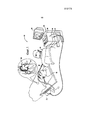
Фиг.2 представляет собой боковое изображение катетера, предназначенного для использования совместно с системой на фиг.1, в соответствии с вариантом реализации настоящего изобретения.FIG. 2 is a side view of a catheter for use with the system of FIG. 1, in accordance with an embodiment of the present invention.
Фиг.3 представляет собой схематичное изображение в разрезе, демонстрирующее подробности дистального сегмента катетера, представленного на фиг.2.FIG. 3 is a schematic sectional view showing details of a distal catheter segment of FIG. 2.
Фиг.4 представляет собой схематичное подробное изображение, демонстрирующее дистальный сегмент, представленный на фиг.3, в контакте с тканью эндокарда.FIG. 4 is a schematic detailed view showing the distal segment shown in FIG. 3 in contact with endocardial tissue.
ПОДРОБНОЕ ОПИСАНИЕ ИЗОБРЕТЕНИЯDETAILED DESCRIPTION OF THE INVENTION
Предметом настоящего изобретения является система с катетером, предназначенная для выполнения катетеризации сердца, в которой катетер имеет сенсорный узел, генерирующий импульсы, характеризующие как положение катетера, так и давление, прилагаемое к дистальному сегменту катетера при контакте с тканью. По сравнению с традиционными приборами распознавания положения и приборами распознавания давления сенсорное устройство механизма данного катетера имеет преимущества, связанные с использованием серийно-проводных сенсорных устройств с сокращенным числом кабелей или их длины, что упрощает структуру и позволяет минимизировать риск повреждения или выхода кабелей из строя.An object of the present invention is a catheter system for performing cardiac catheterization, in which the catheter has a sensor unit generating pulses characterizing both the position of the catheter and the pressure applied to the distal segment of the catheter in contact with the tissue. Compared with traditional position recognition devices and pressure recognition devices, the catheter’s sensor device has the advantages of using serial-wired sensor devices with a reduced number of cables or their lengths, which simplifies the structure and minimizes the risk of damage or cable failure.
Фиг.1 представляет собой схематичную наглядную иллюстрацию традиционной системы 20, предназначенной для проведения катетеризации сердца, известную в данной области техники. Система 20 может быть основана, например, на системе CARTO.TM., которую производит Biosense Webster Inc. (Diamond Bar, Calif.). Данная система содержит инвазивный зонд в виде катетера 28 и пульт управления 34. В одном из вариантов реализации настоящего изобретения, описанном ниже, предполагается, что катетер 28 используется для абляции (удаления) ткани эндокарда, как известно в данной области. В альтернативном варианте соответственно измененный катетер может быть использован для других лечебных или диагностических целей в сердце или другом органе тела. Как изображено на фиг.2, катетер 28 состоит из удлиненного корпуса катетера 11, отклоняемого промежуточного сегмента 12, дистального сегмента 13, несущего как минимум концевой электрод 15 на своем периферическом конце 30, а также рычага управления 16.Figure 1 is a schematic pictorial illustration of a
Оператор 26, например кардиолог, вводит катетер 28 через сосудистую систему пациента 24 таким образом, что дистальный сегмент 13 катетера проникает в камеру сердца 22 пациента. Оператор продвигает катетер так, что дистальный конец 30 катетера приходит в контакт с тканью эндокарда 70 в заданном участке или участках. Катетер 28 в его центральной оконечности соединен посредством подходящего соединителя с пультом управления 34. Пульт управления может состоять из радиочастотного (РЧ) генератора, который поставляет высокочастотную электрическую энергию через катетер для абляции (удаления) ткани сердца в зонах контакта с периферическим сегментом 13. Альтернативно или дополнительно катетер и система могут быть отфигурированы для выполнения других лечебных и диагностических процедур, известных в данной области.An
Пульт управления 34 использует магнитное зондирование для распознавания данных о давлении и положении, включая (i) осевое смещение и угловое отклонение дистального сегмента 13 в зависимости от давления в месте контакта с тканью эндокарда 70, а также (ii) координаты положения дистального сегмента 13 в сердце. С целью получения данных о давлении, включая осевое смещение и угловое отклонение дистального сегмента 13 катетера 28, цепь управления 38 консоли 34 управляет миниатюрным генератором магнитного поля MF, помещенным в периферической части 13D концевого сегмента 13, как показано на фиг.3. В одном из раскрытых вариантов реализации настоящего изобретения генератор поля MF представляет собой катушку, ось которой соосна оси Z, совпадающей с продольной осью 25 катетера.The
Для обнаружения и измерения давления дистальный сегмент 13 имеет центральный участок 13P и дистальный участок 13D, которые соединены друг с другом с помощью гибкого и эластичного соединения 54, которое может быть выполнено из любого подходящего материала с заданными показателями гибкости и прочности. Эластичное соединение 54 допускает ограниченный диапазон относительной подвижности между участками 13P и 13D в ответ на воздействия сил, приложенных к дистальному сегменту 13. Такие силы возникают, когда дистальный конец 30 сжимается на эндокарде в ходе процедуры абляции. Как показано на фиг.4, дистальный конец 30 катетера 28 находится в контакте с эндокардом 70 сердца 22 в соответствии с одним из вариантов реализации настоящего изобретения. Давление, оказываемое периферическим концом 30 на эндокард, деформирует ткань эндокарда незначительно, так что концевой электрод 15 контактирует с тканью на относительно большом участке. Если электрод взаимодействует с эндокардом под углом, а не прямо, дистальный участок 13D изгибается в соединении 54 относительно центрального участка 13З. Изгиб способствует оптимальному контакту между электродом 15 и тканью эндокарда 70.To detect and measure pressure, the
Как показано на фиг.3, соединение 54 включает внешнюю трубку 56, которой может служить внешняя трубка 55 дистального сегмента 13, выполненная из гибкого изолирующего материала, такого как Celcon.RTM., Teflon.RTM или термостойкий полиуретан. Или же трубка 56 может быть выполнена из материала, специально предназначенного для обеспечения беспрепятственного изгибания и сжатия соединения. (Изображение такого материала на фиг.3 удалено для того, чтобы продемонстрировать внутреннее устройство катетера.) Дистальный участок 13D, как правило, относительно жесткий по сравнению с остальной частью катетера.As shown in FIG. 3,
Кроме того, соединение 54 содержит также упругий соединительный элемент 60 в виде пружины или полой детали из эластичного материала с винтовой резьбой по длине. Эластичный материал может быть представлен, например, полимером, таким как силикон, полиуретан, или пластмассами, или суперэластичным сплавом, таким как никель-титановый (Nitinol). Спиральный канал заставляет трубчатый фрагмент работать как пружину в ответ на воздействия, оказываемые на дистальный сегмент 13D. Дополнительные подробности относительно изготовления и технических параметров данного вида соединительных элементов представлены в патентной заявке, зарегистрированной в США, под серийным №12/134592 от 6 июня 2008, которая переуступлена правопреемнику настоящей патентной заявки, раскрытие ее сущности включено в данный документ в качестве ссылки. В качестве альтернативы данный соединительный элемент может содержать любой другой подходящий вид пружинного устройства с заданными параметрами упругости и прочности.In addition, the
Жесткость соединительного элемента 60 определяет амплитуду относительного перемещения дистальных сегментов 13P и 13D в ответ на силы, приложенные к дистальному сегменту 13D. Такие силы возникают при надавливании дистальной части 30 наконечника на эндокард в ходе процедур картирования или абляции. Для хорошего электрического контакта между дистальным сегментом 13D и эндокардом в ходе абляции заданное давление должно составлять порядка 20–30 грамм. Соединительный элемент 60 устроен таким образом, чтобы обеспечить продольное смещение (то есть боковое движение вдоль продольной оси 25 катетера 28) и угловое отклонение дистального сегмента 13D пропорционально надавливанию на дистальный конец 30 наконечника. Измерение смещения и отклонения определяет величину давления и таким образом помогает убедиться, что в ходе абляции давление применяется правильно.The stiffness of the connecting
Электромагнитное или магнитное поле, создаваемое внутренним генератором поля MF, вмонтированным в дистальный сегмент 13D, зондируется и распознается с помощью датчика основного узла 17, который вмонтирован в центральный сегмент 13P. В показанном варианте основной узел датчиков 17 включает катушки датчика S1, S2 и S3, расположенные в центральном сегменте 13D дистальной зоны 13. Каждая из этих катушек в целом параллельна оси Z или продольной оси 25. Все три катушки расположены в основной осевой зоне под различными азимутальными углами по отношению к продольной оси 25 или оси Z, здесь осевая плоскость определена как плоскость, перпендикулярная продольной оси катетера или оси Z, а осевая зона определена как зона, заключенная между двумя осевыми плоскостями катетера. Три катушки могут быть расположены в пространстве отдельно друг друга по азимуту 120 градусов на одинаковом радиальном расстоянии от оси.An electromagnetic or magnetic field generated by the internal field generator MF mounted in the
Осевое смещение или угловое отклонение дистального сегмента 13D относительно центрального сегмента 13P порождает дифференциальное изменение выходного сигнала катушек S1, S2 и S3 в зависимости от направления и величины отклонения, когда одна или две из этих катушек двигаются относительно близко к генератору поля MF. Компрессионное смещение дистального сегмента 13D приводит к увеличению сигналов от каждой из катушек S1, S2 и S3. Изменение направления магнитного поля генератором поля MF заставляет катушки S1, S2 и S3 создавать электрические сигналы с амплитудами, которые указывают на такие смещения или угловые отклонения. Процессор обработки сигналов 36 получает и обрабатывает сигналы, созданные катушками S1, S2 и S3, чтобы определить показатель давления, оказываемого дистальной зоной 13 на эндокард 70.The axial displacement or angular deviation of the
Для получения данных о положении или координатах цепь управления генератором 38 консоли 34 включает внешние генераторы магнитного поля, например F1, F2 и F3, чтобы создать магнитные поля в зоне заданных координат тела пациента 24 и определить внешние границы опорного сигнала. Генераторы F1, F2 и F3 оснащены катушками, которые располагаются снаружи под туловищем пациента на определенных положениях. Данные катушки создают магнитные поля внутри тела пациента в предопределенном рабочем объеме, который включает сердце 22.To obtain position or coordinate information, the control circuit of the
Дополнительный узел датчиков 18 размещен в центральном сегменте 13P проксимальнее основного узла датчиков 17 для реагирования на поля генераторов F1, F2 и F3 и создания электрических сигналов. В показанном варианте узел датчиков 18 включает как минимум две миниатюрные измерительные катушки Sx и Sy без сердечника. Оси катушек, как правило, взаимно ортогональны друг другу и как минимум с осью одной катушки основного узла датчиков 17, например катушки S1. Таким образом, внутри системы координат (Х, Y, Z) катушка Sx выровнена с осью X, катушка Sy выровнена с осью Y, обе катушки ортогональны катушке S1, выровненной с осью Z.An
Две катушки (Sx и Sy) расположены в дополнительной осевой зоне (например, проксимально от основной осевой зоны основного узла датчиков 17) под различными азимутальными углами относительно продольной оси 25 и оси Z, где осевая плоскость определена как плоскость, перпендикулярная оси катетера или оси Z, и ограничена внутри двух осевых плоскостей катетера. Две катушки могут быть расположены в пространстве отдельно по азимуту 120 градусов по отношению друг к другу и относительно катушки S1 основного узла датчиков 17 на одинаковом радиальном расстоянии от оси.Two coils (Sx and Sy) are located in the additional axial zone (for example, proximal from the main axial zone of the main sensor assembly 17) at different azimuthal angles with respect to the
Электромагнитное или магнитное поле создаются внешними генераторами полей F1, F2, F3 и воспринимаются с помощью катушек S1, Sx и Sy с целью определения положения катетера. Под влиянием магнитных полей, создаваемых генераторами полей F1, F2 и F3, катушки S1, Sx и Sy создают электрические сигналы с амплитудами, показывающими положение дистального сегмента 13, соотносящееся с фиксированными рамками опорного сигнала генераторов полей F1, F2 и F3. В одном варианте три генератора полей F1, F2 и F3 генерируют магнитное поле, состоящее из трех по-разному ориентированных компонентов. Каждый из этих компонентов поля определяется катушкой S1, Sx и Sy, каждая из которых создает сигнал, состоящий из трех компонентов.An electromagnetic or magnetic field is created by external field generators F1, F2, F3 and is sensed using coils S1, Sx and Sy in order to determine the position of the catheter. Under the influence of the magnetic fields generated by the field generators F1, F2 and F3, the coils S1, Sx and Sy generate electrical signals with amplitudes showing the position of the
Как показано на фиг.1, процессор обработки сигналов 36 панели управления 34 обрабатывает данные сигналы от катушек S1, Sx и Sy с целью определить координаты положения дистального сегмента 13, включая, как правило, как координаты расположения, так и координаты ориентации. Похожий способ определения положения реализован в вышеупомянутой системе CARTO и подробно описан в зарегистрированных в США патентах № 5391199, 6690963, 6484118, 6239724, 6618612 и 6332089, патенте договора о патентной кооперации WO 96/05768 и в опубликованных в США патентных заявках 2002/0065455 A1, 2003/0120150 A1 и 2004/0068178 A1, все их раскрытия включены в данный документ в виде ссылки.As shown in FIG. 1, the
Сигналы от основного узла датчиков 17 и дополнительного узла датчиков 18 передаются на процессор обработки сигналов 36 по кабелям. В соответствии с особенностью настоящего изобретения выбранные датчики из основного узла датчиков 17 и дополнительного узла датчиков 18 последовательно соединяются, общие кабели совместно используются для передачи сигналов датчиков на процессор обработки сигналов. В представленном на фиг.3 варианте кабели 63, 64A и 65A отходят от датчиков S1, S2 и S3 соответственно. Кабель 63 ведет от датчика S1 к процессору обработки сигналов 36. Кабель 64A ведет от датчика S2 к датчику Sx, соединяя их последовательно. Кабель 65A ведет от датчика S3 к датчику Sy, соединяя их последовательно.The signals from the
Как описано выше, каждый из датчиков S1, S2 и S3 создает сигналы, характерные для воздействия давлением (включая осевое смещение и угловое отклонение) на дистальный сегмент 13, полученные путем распознавания магнитного поля, созданного внутренним генератором полей MF. Выше также описано, что каждый из датчиков S1, Sx и Sy создает сигналы, соответствующие положению дистального сегмента, полученные путем распознавания каждого магнитного поля, созданного внешними генераторами поля F1, F2 и F3.As described above, each of the sensors S1, S2, and S3 generates signals characteristic of pressure (including axial displacement and angular deflection) on the
Соответственно по кабелю 63 на процессор обработки сигналов 36 передаются сигналы, созданные датчиком S1 и характерные для воздействия давлением. По кабелю 64B на процессор обработки сигналов 36 передаются 2 вида сигналов: созданный датчиком S2, характерный для воздействия давлением, и созданный датчиком Sx, характерный для изменения положения. По кабелю 65B на процессор обработки сигналов 36 передаются 2 вида сигналов: созданный датчиком S3, характерный для воздействия давлением, и созданный датчиком Sy, характерный для изменения положения. Результирующие комбинированные сигналы, передаваемые по кабелям 64B и 65B, создают общие суммы, которые могут быть разделены с помощью электронной фильтрации, когда рабочие частоты распознавания положения и силы соответственно разделяются в частотном пространстве, что понятно любому специалисту в данной области.Accordingly, signals created by the sensor S1 and characteristic of pressure exposure are transmitted through a
Процессор обработки сигналов 36 как таковой непосредственно связан только с тремя кабелями, а именно с 63, 64B и 65B, для получения сигналов от пяти датчиков положения и давления по сравнению с типичными пятью или шестью кабелями традиционного катетера с пятью или шестью датчиками положения и давления. Более того, кабели 64A и 65A, последовательно соединяющие спаренные датчики, значительно короче.The
Производство каждого кабеля и его монтаж в катетере являются трудоемкими и дорогими. Более того, кабели занимают место в ограниченном пространстве катетера. К тому же кабели чувствительны к повреждениям. Уменьшенное количество или длина кабелей, передающих сигналы на процессор обработки сигналов, предоставляет ряд преимуществ, включая уменьшение времени производства катетера, увеличение общей производительности катетера, снижение производственных затрат.The manufacture of each cable and its installation in the catheter are laborious and expensive. Moreover, the cables occupy space in the confined space of the catheter. In addition, cables are susceptible to damage. The reduced number or length of cables that transmit signals to the signal processor provides several advantages, including reduced catheter production time, increased overall catheter performance, and reduced manufacturing costs.
Следует понимать, что настоящим изобретением предусмотрены для серийной проводки или соединения различные пары датчиков. В альтернативных вариантах могут быть последовательно соединены, например, датчики S1 и Sx с S2 и Sy или датчики S3 и Sx с S1 и Sy. Для датчиков S1, S2, S3, Sx и Sy существуют шесть возможных перестановок спаривания, в том числе возможны одна или две последовательно соединенные пары в периферическом сегменте 13.It should be understood that the present invention provides for a variety of wiring or connecting various pairs of sensors. In alternative embodiments, for example, sensors S1 and Sx with S2 and Sy or sensors S3 and Sx with S1 and Sy can be connected in series. For sensors S1, S2, S3, Sx and Sy, there are six possible pairing permutations, including one or two series-connected pairs in the
Поскольку в дистальной части 13D катушка генератора MF радиально симметрична, она хорошо подходит для осевого выравнивания с продольной осью 25 катетера. Однако следует понимать, что катушка также может быть внеосевой по желанию либо необходимости, внеосевой наклон катушки будет одновременно улучшать конкретную катушку и ухудшать другую катушку взаимно ортогональных датчиков.Since the coil of the MF generator is radially symmetrical in the
Понятно также, что катушки основного и дополнительного узлов датчиков 17 и 18 могут быть любого подходящего размера и формы при условии их соответствия ограничениям компоновки внутри дистального сегмента 13 в отношении выравнивания или взаимной ортогональности. Традиционные датчики давления, как правило, цилиндрические, то есть длиннее и уже, из-за выравнивания оси Z с генератором MF в пределах дистального сегмента, в то время как традиционные датчики положения X и Y, как правило, имеют более эллиптическую форму, чтобы таким образом поддерживать взаимную ортогональность с датчиком Z положения в соответствии с ограничениями компоновки дистального сегмента. В раскрытом варианте данного изобретения датчики S1, S2 и S3 настраиваются более как традиционные датчики давления и таким образом относительно длиннее и уже, в то время как датчики Sx и Sy настраиваются как более традиционные датчики положения и таким образом являются более эллиптическими. Датчики положения и давления описаны в патентах США № 6690963 и публикации США № 20090138007, публичные раскрытия которых включены в настоящий документ в качестве ссылки. В показанном варианте катушки датчиков S1, S2 и S3 сконфигурированы как датчики положения, а катушки датчиков Sx и Sy - как датчики давления.It is also clear that the coils of the main and additional nodes of the
Генераторы полей F1, F2, F3 и MF создают магнитные поля, которые различимы в отношении разных параметров, включая частоту, фазу или время; катушки датчиков S1, S2, S3, Sx и Sy генерируют сигналы от изменения потока магнитного поля различимых магнитных полей, сигналы катушек датчиков также различимы. Частота, фаза или время мультиплексирования применяются в случае необходимости или по желанию. Например, ток к генератору давления MF может вырабатываться на выбранной частоте в диапазоне около 16 и 25 кГц, в то время как генераторы положения F1, F2 и F3 приводятся в движение на различных частотах.Field generators F1, F2, F3 and MF create magnetic fields that are distinguishable with respect to various parameters, including frequency, phase or time; the coils of the sensors S1, S2, S3, Sx and Sy generate signals from changes in the magnetic flux of the distinguishable magnetic fields, the signals of the sensor coils are also distinguishable. The frequency, phase or time of multiplexing is applied if necessary or at will. For example, current to the pressure generator MF can be generated at a selected frequency in the range of about 16 and 25 kHz, while position generators F1, F2 and F3 are driven at different frequencies.
Процессор обработки сигналов 36 обрабатывает сигналы с целью определения данных, включая (i) координаты положения дистального сегмента 13, обычно как расположения, так и ориентации, и (ii) осевое смещение и угловое отклонение периферического сегмента 13. Процессор обработки сигналов 36 может содержать компьютер общего назначения с подходящим устройством предварительной обработки данных и схемами интерфейса для получения сигналов от катетера 28 и контроля других компонентов панели управления 34. Для осуществления описанных в настоящем документе функций процессор может быть снабжен специальным программным обеспечением. Программное обеспечение можно загрузить на панель управления 34 в электронном виде, например в сети, или оно может быть предоставлено на носителях, таких как оптические, магнитные или электронные устройства памяти. В другом варианте некоторые или все функции процессора 36 могут выполняться специализированными или программируемыми компонентами цифровых аппаратных средств. На основе сигналов, получаемых от катетера и других компонентов системы 20, процессор 36 управляет дисплеем 42, который предоставляет оператору 26 визуальную обратную связь о положении дистального конца 30 в теле пациента, а также относительном осевом смещении и угловом отклонении дистального наконечника катетера и информацию о состоянии и рекомендации относительно текущей процедуры.The
Процессор 36 получает эти сигналы по кабелям 63, 64B и 65B, идущим через катетер 28, и обрабатывает их с целью получить координаты положения и ориентации дистального сегмента 13 в данной фиксированной системе координат, а также получить информацию об оказываемом давлении, включая осевое смещение и угловое отклонение дистального сегмента. Расположение катушек S1, S2, S3, Sx и Sy и давление, оказываемое на дистальный сегмент 13D дистальной зоны 13, могут быть рассчитаны по характеристикам полей, таким как сила и направление, определяемым с помощью катушек. Таким образом, генераторы полей F1, F2, F3 и MF и катушки зондирования S1, S2, S3, Sx и Sy совместно определяют множество пар «передатчик-приемник», где каждая такая пара включает один генератор поля и катушку как элемент пары, каждая катушка расположена в положении и ориентации, отличной от других катушек. Определяя характеристики передачи полей между элементами различных пар, система раскрывает данные о положении и давлении от последовательно соединенных датчиков с целью отследить информацию, относящуюся к расположению дистальной зоны 13 во внешних рамках, как определяется генераторами полей F1, F2, и F3 и информацией, относящейся к давлению, оказываемому на дистальный сегмент MF, как зарегистрировано в магнитном поле, созданном генератором поля MF. Информация о положении может включать положение дистальной зоны 13, ориентацию дистальной зоны 13 либо и то и другое. Как понятно любому специалисту в данной области техники, вычисление информации о положении зависит от расположения генераторов полей F1, F2 и F3 в известных положениях и их ориентации относительно друг друга, а вычисление давления, основанное на осевом смещении и угловом отклонении, зависит от расположения генератора поля MF и катушек датчиков S1, S1 и S3 в известных положениях и их ориентации относительно друг друга.The
Катушки F1, F2, F3 и MF, создающие поле, являются одним из типов магнитного преобразователя, который может использоваться в вариантах данного изобретения. Магнитный преобразователь в контексте данной патентной заявки и в формуле изобретения - это прибор, который может генерировать магнитное поле в ответ на поданный электрический ток или выдавать электрический ток в ответ на поданное магнитное поле. Несмотря на то что в описанном варианте в роли магнитного преобразователя используются катушки, в альтернативных вариантах могут использоваться другие типы магнитных преобразователей, что понятно для специалистов в этой отрасли.The field coils F1, F2, F3 and MF are one type of magnetic transducer that can be used in embodiments of the present invention. A magnetic transducer in the context of this patent application and in the claims is a device that can generate a magnetic field in response to a supplied electric current or produce an electric current in response to a supplied magnetic field. Despite the fact that in the described embodiment, coils are used as a magnetic transducer, in alternative embodiments other types of magnetic transducers can be used, which is understandable for specialists in this field.
В дополнение к вышеописанным в измерительном узле могут использоваться различные иные конфигурации катушек. Например, положения генератора поля MF и катушек S1, S2 и S3 могут быть обратны, генератор поля MF может располагаться в проксимальной части 13D проксимальнее шарнира 54, а измерительные катушки будут находиться в дистальной части 13D. В другом варианте катушки S1, S2 и S3 будут служить генераторами магнитного поля (используя мультиплексирование по времени или частоте), в то время как катушка генератора поля MF будет работать как измеритель. Размеры и формы передающих и измерительных катушек, показанные на фиг.3 только для примера, можно использовать большее или меньшее количество катушек в различных положениях, чтобы узел содержал хотя бы две катушки в различных радиальных положениях для дифференциального измерения отклонения шарнира.In addition to the above, various other coil configurations may be used in the measurement assembly. For example, the positions of the field generator MF and coils S1, S2 and S3 may be reversed, the field generator MF may be located in the
В соответствии с другой частью данного изобретения, так как катушки Sx и Sy перпендикулярны и не соосны с осью миниатюрного генератора поля MF, его магнитное поле диполя можно обнаружить с помощью перпендикулярных катушек Sx и Sy. Катушки Sx и SCY могут фиксировать относительно слабое магнитное поле, создаваемое генератором MF, по сравнению с катушками S1, S2 и S3 из-за их соответствующей ориентации по отношению к генератору магнитного поля MF, при этом повышенная чувствительность ведет к помехам, создаваемым близостью к валу, то есть изменения в магнитном поле могут быть следствием создания магнитного поля генератором MF, отслеживаемого катушками S1, S2 и S3, из-за физической деформации дистальной секции 13 в результате взаимодействия с тканью или просто следствием магнитных помех от металлических или железных элементов или смежных катетеров.According to another part of the present invention, since the coils Sx and Sy are perpendicular and not aligned with the axis of the miniature field generator MF, its dipole magnetic field can be detected using perpendicular coils Sx and Sy. The coils Sx and SCY can detect the relatively weak magnetic field generated by the MF generator compared to the coils S1, S2 and S3 due to their corresponding orientation with respect to the magnetic field generator MF, while the increased sensitivity leads to interference caused by proximity to the shaft , that is, changes in the magnetic field may be due to the creation of a magnetic field by the generator MF, tracked by coils S1, S2 and S3, due to the physical deformation of the
Данное изобретение успешно использует сигналы от датчиков Sx и Sy, таких как возврат и проверка ошибки. Во время производства и установки катетера 28 сигналы измерителей Sx и Sy, которые производятся в ответ на внутренний генератор поля MF вне зависимости от влияния других близлежащих катетеров или металлических элементов, калибруются и сохраняются в память консоли 34. Так как эти сигналы слабее, чем те, которые создаются в датчиках S1, S2 и S3 в ответ на внутренний генератор поля, сигналы от Sx и Sy имеют уникальные признаки или характеристики. Поэтому, когда катетер 28 использует внутренний генератор поля для создания магнитного поля, которое считывается измерительными катушками Sx и Sy для определения давления, измерительные катушки Sx и Sy второго измерительного узла 18, считывая магнитные поля внешних генераторов поля F1, F2 и F3, также определяют магнитное поле внутреннего генератора поля MF. Сигнальный процессор 36 получает сигналы от датчиков Sx и Sy и идентифицирует сигналы, идущие от внутреннего генератора поля MF (в сравнении с теми, которые получаются под действием магнитного поля внешних генераторов поля F1, F2 и F3), и сравнивает с откалиброванными сигналами, сохраненными в памяти. Если сигнальный процессор 36 определяет несоответствие между этим и откалиброванными сигналами, консоль 34 передает индикацию этого несоответствия оператору и может включить визуальный или звуковой сигнал.The present invention successfully utilizes signals from Sx and Sy sensors, such as return and error checking. During the production and installation of the
В одном варианте калибровка давления производится для дистального отдела 13 во время производства и выпуска. Определением деформационных характеристик упругого соединительного элемента 60, приложением на дистальную часть 13D определенной силы под несколькими заданными углами (т. е. компрессионная нагрузка, осевая нагрузка и т. д.) и определением осевого смещения и углового отклонения создается калибровочный файл для сигналов, которые могут быть произведены датчиками S1, S2 и S3 в ответ на магнитное поле, произведенное внутренним генератором поля MF, компилируется в первый файл и сохраняется в памяти. Одновременно калибровочный файл для сигналов, которые могут быть произведены датчиками Sx и Sy в ответ на магнитное поле, произведенное внутренним генератором поля MF, компилируется во втором файле и сохраняется в памяти.In one embodiment, a pressure calibration is performed for the
Когда катетер используется в человеческом теле, сигнальный процессор 36 получает сигналы от датчиков S1, S2 и S3 в ответ на внутренний генератор поля MF и сравнивает эти сигналы с первым файлом, сохраненным в памяти, для получения данных об осевом смещении и угловом отклонении для вывода данных о давлении катетера оператору. Удобно, что процессор 36 также получает сигналы от датчиков Sx и Sy, которые включают их в ответ на внутренний генератор поля MF и сравнивают эти данные со вторым файлом для выявления и идентифицирования несоответствий.When the catheter is used in the human body, the
Одновременно данное изобретение включает способ калибровки катетера для определения влияния магнитного поля, вызванного наличием второго катетера либо другого металлического или железного объекта, включая следующее:At the same time, this invention includes a method for calibrating a catheter to determine the effect of a magnetic field caused by the presence of a second catheter or other metal or iron object, including the following:
1. Обеспечение катетера первым и вторым датчиками, которые приспособлены реагировать на магнитное поле, генерируемое генератором поля.1. Providing a catheter with first and second sensors that are adapted to respond to the magnetic field generated by the field generator.
2. Запуск генератора поля для возможности создания первым и вторым датчиками калибровочных сигналов.2. Starting the field generator to enable the first and second sensors to create calibration signals.
3. Приложение сил осевого смещения и углового отклонения на катетер.3. The application of axial displacement and angular deflection to the catheter.
4. Калибрование калибровочных сигналов первого датчика для создания первого калибровочного файла и калибрование калибровочных сигналов от второго датчика для создания второго калибровочного файла, включая следующее:4. Calibrating the calibration signals of the first sensor to create the first calibration file and calibrating the calibration signals from the second sensor to create the second calibration file, including the following:
а. Приложение сил осевого смещения и углового отклонения на катетер.but. The application of axial displacement and angular deflection to the catheter.
б. Сохранение в памяти данных, представляющих сигналы, генерируемые первым датчиком в ответ на силы, приложенные к катетеру.b. Storing in memory the data representing the signals generated by the first sensor in response to the forces applied to the catheter.
в. Сохранение в памяти данных, представляющих сигналы, генерируемые вторым датчиком в ответ на силы, приложенные к катетеру.at. Storing in memory the data representing the signals generated by the second sensor in response to the forces applied to the catheter.
Данное изобретение включает также способ определения влияния на магнитное поле, определяемое первым катетером, присутствия второго катетера или металлического или железного объекта, включающий следующее:The present invention also includes a method for determining the effect on the magnetic field determined by the first catheter, the presence of a second catheter or a metal or iron object, comprising the following:
1. Обеспечение катетера первым и вторым датчиками, которые приспособлены реагировать на магнитное поле, генерируемое генератором поля.1. Providing a catheter with first and second sensors that are adapted to respond to the magnetic field generated by the field generator.
2. Запуск генератора поля для возможности создания первым и вторым датчиками калибровочных сигналов.2. Starting the field generator to enable the first and second sensors to create calibration signals.
3. Приложение сил осевого смещения и углового отклонения на катетер.3. The application of axial displacement and angular deflection to the catheter.
4. Калибрование калибровочных сигналов первого датчика для создания первого калибровочного файла и калибрование калибровочных сигналов от второго датчика для создания второго калибровочного файла, включая следующее:4. Calibrating the calibration signals of the first sensor to create the first calibration file and calibrating the calibration signals from the second sensor to create the second calibration file, including the following:
а. Приложение сил осевого смещения и углового отклонения на катетер.but. The application of axial displacement and angular deflection to the catheter.
б. Сохранение в памяти данных, представляющих сигналы, генерируемые первым датчиком в ответ на силы, приложенные к катетеру.b. Storing in memory the data representing the signals generated by the first sensor in response to the forces applied to the catheter.
в. Сохранение в памяти данных, представляющих сигналы, генерируемые вторым датчиком в ответ на силы, приложенные к катетеру.at. Storing in memory the data representing the signals generated by the second sensor in response to the forces applied to the catheter.
5. Когда катетер используется, запускается генератор поля для создания сигналов данных первым и вторым датчиками.5. When a catheter is used, a field generator is triggered to generate data signals by the first and second sensors.
6. Сравнение сигналов данных от второго датчика с калибровочными сигналами во втором калибровочном файле.6. Comparison of data signals from the second sensor with calibration signals in the second calibration file.
Способ определения может также включать следующее:The determination method may also include the following:
7. Определения несоответствия между информационными сигналами от второго датчика и калибровочными сигналами во втором калибровочном файле.7. Determination of the mismatch between the information signals from the second sensor and the calibration signals in the second calibration file.
8. Если определяется несоответствие, проводится отображение несоответствия пользователю.8. If a non-compliance is determined, a non-compliance is displayed to the user.
Понятно, что определение несоответствия может проводиться с последовательно подключенными датчиками или без них. Иначе говоря, определение несоответствия использует два комплекта датчиков, например первый измерительный узел 17, а именно датчики S1, S2 и S3, и второй измерительный узел 18, а именно датчики Sx и Sy, в порядке сравнительного отображения. Когда датчики последовательно подключены между первым и вторым измерительными узлами, система может извлекать необходимые данные и сигналы.It is clear that the determination of non-compliance can be carried out with or without sensors connected in series. In other words, the determination of non-compliance uses two sets of sensors, for example, the
Предшествующее описание изложено со ссылкой на конкретные примеры вариантов осуществления изобретения. Специалистам в области техники и технологии, к которой принадлежит настоящее изобретение, будет понятно, что описанная конструкция допускает модификации и изменения, не нарушающие принципы и сущность настоящего изобретения и не выходящие за рамки его объема. Необходимо понимать, что чертежи необязательно сводить к определенному масштабу. Таким образом, предшествующее описание не следует толковать как относящееся только к конкретным конструкциям, раскрытым и представленным на сопроводительных чертежах. Предшествующее описание скорее согласуется и подкрепляет нижеизложенную формулу изобретения, отражающую полный объем настоящего изобретения.The foregoing description is set forth with reference to specific examples of embodiments of the invention. Specialists in the field of engineering and technology to which the present invention belongs, it will be understood that the described construction allows modifications and changes that do not violate the principles and essence of the present invention and do not go beyond its scope. You must understand that the drawings do not have to be reduced to a certain scale. Thus, the foregoing description should not be construed as referring only to the specific structures disclosed and presented in the accompanying drawings. The preceding description is rather consistent and reinforces the following claims, reflecting the full scope of the present invention.
Claims (52)
Applications Claiming Priority (2)
| Application Number | Priority Date | Filing Date | Title |
|---|---|---|---|
| US13/732,324 US9204841B2 (en) | 2012-12-31 | 2012-12-31 | Catheter with serially connected sensing structures and methods of calibration and detection |
| US13/732,324 | 2012-12-31 |
Publications (2)
| Publication Number | Publication Date |
|---|---|
| RU2013158764A RU2013158764A (en) | 2015-07-10 |
| RU2655294C2 true RU2655294C2 (en) | 2018-05-24 |
Family
ID=49911320
Family Applications (1)
| Application Number | Title | Priority Date | Filing Date |
|---|---|---|---|
| RU2013158764A RU2655294C2 (en) | 2012-12-31 | 2013-12-27 | Catheter with serially connected sensing structures and methods of calibration and detection |
Country Status (9)
| Country | Link |
|---|---|
| US (6) | US9204841B2 (en) |
| EP (3) | EP3673847B1 (en) |
| JP (2) | JP6282465B2 (en) |
| CN (1) | CN103908337B (en) |
| AU (5) | AU2013273696B2 (en) |
| CA (1) | CA2838174A1 (en) |
| ES (1) | ES2772124T3 (en) |
| IL (2) | IL230131A (en) |
| RU (1) | RU2655294C2 (en) |
Cited By (1)
| Publication number | Priority date | Publication date | Assignee | Title |
|---|---|---|---|---|
| RU2761291C1 (en) * | 2019-08-15 | 2021-12-06 | Байосенс Вебстер (Изрэйл) Лтд. | Dynamic ablation and investigation depending on the contact of segmented electrodes |
Families Citing this family (58)
| Publication number | Priority date | Publication date | Assignee | Title |
|---|---|---|---|---|
| US8784336B2 (en) | 2005-08-24 | 2014-07-22 | C. R. Bard, Inc. | Stylet apparatuses and methods of manufacture |
| US9521961B2 (en) | 2007-11-26 | 2016-12-20 | C. R. Bard, Inc. | Systems and methods for guiding a medical instrument |
| EP2712547B1 (en) | 2007-11-26 | 2015-09-30 | C. R. Bard, Inc. | Integrated system for intravascular placement of a catheter |
| US8781555B2 (en) | 2007-11-26 | 2014-07-15 | C. R. Bard, Inc. | System for placement of a catheter including a signal-generating stylet |
| US9649048B2 (en) | 2007-11-26 | 2017-05-16 | C. R. Bard, Inc. | Systems and methods for breaching a sterile field for intravascular placement of a catheter |
| US10751509B2 (en) | 2007-11-26 | 2020-08-25 | C. R. Bard, Inc. | Iconic representations for guidance of an indwelling medical device |
| WO2010022370A1 (en) | 2008-08-22 | 2010-02-25 | C.R. Bard, Inc. | Catheter assembly including ecg sensor and magnetic assemblies |
| EP2358278B1 (en) | 2008-12-08 | 2021-05-12 | Acist Medical Systems, Inc. | System and catheter for image guidance and methods thereof |
| US9532724B2 (en) | 2009-06-12 | 2017-01-03 | Bard Access Systems, Inc. | Apparatus and method for catheter navigation using endovascular energy mapping |
| US9445734B2 (en) | 2009-06-12 | 2016-09-20 | Bard Access Systems, Inc. | Devices and methods for endovascular electrography |
| JP2013518676A (en) | 2010-02-02 | 2013-05-23 | シー・アール・バード・インコーポレーテッド | Apparatus and method for locating catheter navigation and tip |
| ES2864665T3 (en) | 2010-05-28 | 2021-10-14 | Bard Inc C R | Apparatus for use with needle insertion guidance system |
| EP2575611B1 (en) | 2010-05-28 | 2021-03-03 | C. R. Bard, Inc. | Apparatus for use with needle insertion guidance system |
| EP2605699A4 (en) | 2010-08-20 | 2015-01-07 | Bard Inc C R | Reconfirmation of ecg-assisted catheter tip placement |
| US9204841B2 (en) * | 2012-12-31 | 2015-12-08 | Biosense Webster (Israel) Ltd. | Catheter with serially connected sensing structures and methods of calibration and detection |
| US9204820B2 (en) * | 2012-12-31 | 2015-12-08 | Biosense Webster (Israel) Ltd. | Catheter with combined position and pressure sensing structures |
| US11179194B2 (en) * | 2013-12-12 | 2021-11-23 | St. Jude Medical, Cardiology Division, Inc. | Medical device with contact force sensing tip |
| US9713456B2 (en) | 2013-12-30 | 2017-07-25 | Acist Medical Systems, Inc. | Position sensing in intravascular imaging |
| WO2015120256A2 (en) | 2014-02-06 | 2015-08-13 | C.R. Bard, Inc. | Systems and methods for guidance and placement of an intravascular device |
| US10888346B2 (en) | 2014-05-18 | 2021-01-12 | Legacy Ventures LLC | Clot retrieval system |
| CN112971985A (en) * | 2014-07-03 | 2021-06-18 | 圣犹达医疗用品国际控股有限公司 | Local magnetic field generator |
| US10973584B2 (en) | 2015-01-19 | 2021-04-13 | Bard Access Systems, Inc. | Device and method for vascular access |
| US10307078B2 (en) * | 2015-02-13 | 2019-06-04 | Biosense Webster (Israel) Ltd | Training of impedance based location system using registered catheter images |
| US10349890B2 (en) | 2015-06-26 | 2019-07-16 | C. R. Bard, Inc. | Connector interface for ECG-based catheter positioning system |
| US10682176B2 (en) | 2015-08-25 | 2020-06-16 | Biosense Webster (Israel) Ltd. | System and method for controlling catheter power based on contact force |
| US10383543B2 (en) * | 2015-11-11 | 2019-08-20 | Biosense Webster (Israel) Ltd. | Symmetric short contact force sensor with four coils |
| CN106806017B (en) * | 2015-12-01 | 2019-08-27 | 四川锦江电子科技有限公司 | A kind of conduit of precise measurement power and direction |
| CN106806016A (en) * | 2015-12-01 | 2017-06-09 | 四川锦江电子科技有限公司 | A kind of ablating device |
| US11000207B2 (en) | 2016-01-29 | 2021-05-11 | C. R. Bard, Inc. | Multiple coil system for tracking a medical device |
| US20170254167A1 (en) * | 2016-03-02 | 2017-09-07 | Hydril Usa Distribution, Llc | Blowout preventer packer insert |
| US10327667B2 (en) | 2016-05-13 | 2019-06-25 | Becton, Dickinson And Company | Electro-magnetic needle catheter insertion system |
| JP6943883B2 (en) * | 2016-05-19 | 2021-10-06 | アシスト・メディカル・システムズ,インコーポレイテッド | Position detection in intravascular processes |
| WO2017201287A1 (en) | 2016-05-19 | 2017-11-23 | Acist Medical Systems, Inc. | Position sensing in intravascular processes |
| US20170347914A1 (en) | 2016-06-01 | 2017-12-07 | Becton, Dickinson And Company | Invasive Medical Devices Including Magnetic Region And Systems And Methods |
| US11826522B2 (en) | 2016-06-01 | 2023-11-28 | Becton, Dickinson And Company | Medical devices, systems and methods utilizing permanent magnet and magnetizable feature |
| US11413429B2 (en) | 2016-06-01 | 2022-08-16 | Becton, Dickinson And Company | Medical devices, systems and methods utilizing permanent magnet and magnetizable feature |
| US10583269B2 (en) * | 2016-06-01 | 2020-03-10 | Becton, Dickinson And Company | Magnetized catheters, devices, uses and methods of using magnetized catheters |
| US10032552B2 (en) | 2016-08-30 | 2018-07-24 | Becton, Dickinson And Company | Cover for tissue penetrating device with integrated magnets and magnetic shielding |
| CN107789051A (en) * | 2016-08-30 | 2018-03-13 | 四川锦江电子科技有限公司 | A kind of catheter pressure detection method, and corresponding conduit |
| CN108143481A (en) * | 2016-12-02 | 2018-06-12 | 四川锦江电子科技有限公司 | A kind of ablation catheter and the ablating device for including this conduit |
| US20190388033A1 (en) * | 2017-02-03 | 2019-12-26 | St. Jude Medical International Holding S.á r.l. | Optical force sensing catheter system |
| JP7242537B2 (en) * | 2017-02-09 | 2023-03-20 | コーニンクレッカ フィリップス エヌ ヴェ | Position detection based on tissue discrimination |
| US11317965B2 (en) | 2017-03-08 | 2022-05-03 | Biosense Webster (Israel) Ltd. | Reduced size force sensor |
| US20180311467A1 (en) * | 2017-04-27 | 2018-11-01 | Ehsan Shameli | Mechanical Force Sensor Based on Eddy Current Sensing |
| US10426559B2 (en) * | 2017-06-30 | 2019-10-01 | Auris Health, Inc. | Systems and methods for medical instrument compression compensation |
| US10359464B2 (en) * | 2017-09-18 | 2019-07-23 | Biosense Webster (Israel) Ltd. | Cable and associated continuity monitoring system and method |
| US11839460B2 (en) * | 2018-06-06 | 2023-12-12 | DePuy Synthes Products, Inc. | Device and method to detect and remove blood clots for treatment of ischemic stroke using force and electromagnetic sensing |
| US20190388156A1 (en) * | 2018-06-20 | 2019-12-26 | Acclarent, Inc. | Medical instrument with multi-coil position sensor |
| US11672461B2 (en) * | 2018-07-16 | 2023-06-13 | Biosense Webster (Israel) Ltd. | Flexible circuit with location and force-sensor coils |
| US20200046420A1 (en) * | 2018-08-08 | 2020-02-13 | Biosense Webster (Israel) Ltd. | Contact force sensor comprising tuned amplifiers |
| US11666203B2 (en) * | 2018-10-04 | 2023-06-06 | Biosense Webster (Israel) Ltd. | Using a camera with an ENT tool |
| WO2020081373A1 (en) | 2018-10-16 | 2020-04-23 | Bard Access Systems, Inc. | Safety-equipped connection systems and methods thereof for establishing electrical connections |
| US10973588B2 (en) * | 2018-10-24 | 2021-04-13 | Biosense Webster (Israel) Ltd. | On-the-fly calibration for catheter location and orientation |
| US11633229B2 (en) | 2019-10-07 | 2023-04-25 | Biosense Webster (Israel) Ltd. | 3D electrical activity representation |
| EP4081112B1 (en) | 2020-02-06 | 2023-11-01 | St. Jude Medical International Holding S.à r.l. | Hybrid approach to distortion detection |
| CN114271924B (en) * | 2020-09-27 | 2024-03-01 | 四川锦江电子医疗器械科技股份有限公司 | Catheter calibration method and device based on grid partition |
| CN112120791B (en) * | 2020-09-30 | 2021-12-31 | 中国科学院深圳先进技术研究院 | Main end control device of vascular intervention surgical robot |
| EP4338695A1 (en) | 2022-09-11 | 2024-03-20 | Biosense Webster (Israel) Ltd. | System for combined ablation modalities |
Citations (4)
| Publication number | Priority date | Publication date | Assignee | Title |
|---|---|---|---|---|
| US20020065455A1 (en) * | 1995-01-24 | 2002-05-30 | Shlomo Ben-Haim | Medical diagnosis, treatment and imaging systems |
| EP2338411A1 (en) * | 2009-12-23 | 2011-06-29 | Biosense Webster (Israel), Ltd | Calibration system for a pressure-sensitive catheter |
| US20120041295A1 (en) * | 2010-08-16 | 2012-02-16 | Schultz Jeffrey W | Catheter with thin film pressure sensing distal tip |
| EP2462869A1 (en) * | 2010-12-10 | 2012-06-13 | Biosense Webster (Israel), Ltd. | System and method for detection of metal disturbance based on mutual inductance measurement |
Family Cites Families (33)
| Publication number | Priority date | Publication date | Assignee | Title |
|---|---|---|---|---|
| US5391199A (en) | 1993-07-20 | 1995-02-21 | Biosense, Inc. | Apparatus and method for treating cardiac arrhythmias |
| IL116699A (en) | 1996-01-08 | 2001-09-13 | Biosense Ltd | Method of constructing cardiac map |
| US5558091A (en) | 1993-10-06 | 1996-09-24 | Biosense, Inc. | Magnetic determination of position and orientation |
| CN1226960C (en) | 1994-08-19 | 2005-11-16 | 生物感觉有限公司 | Medical diagnosis, treatment and imaging systems |
| US5752513A (en) | 1995-06-07 | 1998-05-19 | Biosense, Inc. | Method and apparatus for determining position of object |
| CA2246287C (en) | 1996-02-15 | 2006-10-24 | Biosense, Inc. | Medical procedures and apparatus using intrabody probes |
| CA2246290C (en) | 1996-02-15 | 2008-12-23 | Biosense, Inc. | Independently positionable transducers for location system |
| JP3949729B2 (en) | 1997-01-03 | 2007-07-25 | バイオセンス・インコーポレイテッド | Shape adaptive catheter |
| US6239724B1 (en) | 1997-12-30 | 2001-05-29 | Remon Medical Technologies, Ltd. | System and method for telemetrically providing intrabody spatial position |
| DE69928783T2 (en) | 1998-03-30 | 2006-08-03 | Biosense Webster, Inc., Diamond Bar | THREE-DIMENSIONED MAGNETIC COIL SENSOR |
| AU4644799A (en) * | 1998-08-02 | 2000-03-14 | Super Dimension Ltd. | Intrabody navigation system for medical applications |
| US6892091B1 (en) | 2000-02-18 | 2005-05-10 | Biosense, Inc. | Catheter, method and apparatus for generating an electrical map of a chamber of the heart |
| US7809421B1 (en) | 2000-07-20 | 2010-10-05 | Biosense, Inc. | Medical system calibration with static metal compensation |
| US6484118B1 (en) | 2000-07-20 | 2002-11-19 | Biosense, Inc. | Electromagnetic position single axis system |
| US7729742B2 (en) | 2001-12-21 | 2010-06-01 | Biosense, Inc. | Wireless position sensor |
| US20040068178A1 (en) | 2002-09-17 | 2004-04-08 | Assaf Govari | High-gradient recursive locating system |
| US7697972B2 (en) | 2002-11-19 | 2010-04-13 | Medtronic Navigation, Inc. | Navigation system for cardiac therapies |
| US7536218B2 (en) | 2005-07-15 | 2009-05-19 | Biosense Webster, Inc. | Hybrid magnetic-based and impedance-based position sensing |
| AU2006305967B2 (en) | 2005-10-27 | 2013-02-07 | St. Jude Medical, Atrial Fibrillation Division, Inc. | Systems and methods for electrode contact assessment |
| US7860553B2 (en) * | 2006-02-09 | 2010-12-28 | Biosense Webster, Inc. | Two-stage calibration of medical probes |
| US7688064B2 (en) | 2006-07-11 | 2010-03-30 | Biosense Webster Inc. | Probe for assessment of metal distortion |
| US8535308B2 (en) | 2007-10-08 | 2013-09-17 | Biosense Webster (Israel), Ltd. | High-sensitivity pressure-sensing probe |
| US8357152B2 (en) | 2007-10-08 | 2013-01-22 | Biosense Webster (Israel), Ltd. | Catheter with pressure sensing |
| US8437832B2 (en) | 2008-06-06 | 2013-05-07 | Biosense Webster, Inc. | Catheter with bendable tip |
| US20110196397A1 (en) | 2008-10-10 | 2011-08-11 | Vasostar, Inc. | Medical device with a guidewire for penetrating occlusions |
| US20110066029A1 (en) | 2009-09-11 | 2011-03-17 | Medtronic, Inc. | Electromagnetic Medical Device |
| US8979772B2 (en) | 2010-11-03 | 2015-03-17 | Biosense Webster (Israel), Ltd. | Zero-drift detection and correction in contact force measurements |
| US10307205B2 (en) * | 2010-12-10 | 2019-06-04 | Biosense Webster (Israel) Ltd. | System and method for detection of metal disturbance based on orthogonal field components |
| US20130303878A1 (en) | 2011-01-20 | 2013-11-14 | Enav Medical Ltd. | System and method to estimate location and orientation of an object |
| US8333103B2 (en) | 2011-03-30 | 2012-12-18 | Biosense Webster (Israel), Ltd. | Calibration of a force measuring system for large bend angles of a catheter |
| ITTO20110394A1 (en) | 2011-05-05 | 2012-11-06 | Univ Pisa | CATHETER EQUIPPED WITH ELECTROMAGNETIC POSITION SENSORS, AND LOCALIZATION SYSTEM FOR CATHETER AND WIRE GUIDES |
| US9204820B2 (en) * | 2012-12-31 | 2015-12-08 | Biosense Webster (Israel) Ltd. | Catheter with combined position and pressure sensing structures |
| US9204841B2 (en) * | 2012-12-31 | 2015-12-08 | Biosense Webster (Israel) Ltd. | Catheter with serially connected sensing structures and methods of calibration and detection |
-
2012
- 2012-12-31 US US13/732,324 patent/US9204841B2/en active Active
-
2013
- 2013-12-19 AU AU2013273696A patent/AU2013273696B2/en not_active Ceased
- 2013-12-23 CA CA2838174A patent/CA2838174A1/en not_active Abandoned
- 2013-12-24 EP EP19213271.0A patent/EP3673847B1/en active Active
- 2013-12-24 IL IL230131A patent/IL230131A/en active IP Right Grant
- 2013-12-24 EP EP13199522.7A patent/EP2749240B1/en active Active
- 2013-12-24 EP EP14167950.6A patent/EP2774568B1/en active Active
- 2013-12-24 ES ES14167950T patent/ES2772124T3/en active Active
- 2013-12-27 JP JP2013271834A patent/JP6282465B2/en active Active
- 2013-12-27 RU RU2013158764A patent/RU2655294C2/en not_active IP Right Cessation
- 2013-12-31 CN CN201310752026.7A patent/CN103908337B/en active Active
-
2015
- 2015-12-04 US US14/960,273 patent/US9492639B2/en active Active
-
2016
- 2016-11-14 US US15/351,346 patent/US9861785B2/en active Active
-
2017
- 2017-04-03 IL IL251540A patent/IL251540B/en active IP Right Grant
- 2017-12-20 JP JP2017243738A patent/JP6615852B2/en active Active
-
2018
- 2018-01-08 US US15/865,215 patent/US10195396B2/en active Active
- 2018-10-26 AU AU2018253584A patent/AU2018253584A1/en not_active Abandoned
- 2018-10-26 AU AU2018253583A patent/AU2018253583A1/en not_active Abandoned
- 2018-10-26 AU AU2018253585A patent/AU2018253585B2/en not_active Ceased
-
2019
- 2019-02-04 US US16/267,261 patent/US11135400B2/en active Active
- 2019-08-19 AU AU2019219708A patent/AU2019219708A1/en not_active Withdrawn
-
2021
- 2021-10-04 US US17/493,711 patent/US20220032009A1/en active Pending
Patent Citations (5)
| Publication number | Priority date | Publication date | Assignee | Title |
|---|---|---|---|---|
| US20020065455A1 (en) * | 1995-01-24 | 2002-05-30 | Shlomo Ben-Haim | Medical diagnosis, treatment and imaging systems |
| EP2338411A1 (en) * | 2009-12-23 | 2011-06-29 | Biosense Webster (Israel), Ltd | Calibration system for a pressure-sensitive catheter |
| RU2010152701A (en) * | 2009-12-23 | 2012-06-27 | Байосенс Вебстер (Изрэйл), Лтд. (Il) | CALIBRATION SYSTEM FOR PRESSURE SENSITIVE CATHETERS |
| US20120041295A1 (en) * | 2010-08-16 | 2012-02-16 | Schultz Jeffrey W | Catheter with thin film pressure sensing distal tip |
| EP2462869A1 (en) * | 2010-12-10 | 2012-06-13 | Biosense Webster (Israel), Ltd. | System and method for detection of metal disturbance based on mutual inductance measurement |
Cited By (1)
| Publication number | Priority date | Publication date | Assignee | Title |
|---|---|---|---|---|
| RU2761291C1 (en) * | 2019-08-15 | 2021-12-06 | Байосенс Вебстер (Изрэйл) Лтд. | Dynamic ablation and investigation depending on the contact of segmented electrodes |
Also Published As
Similar Documents
| Publication | Publication Date | Title |
|---|---|---|
| RU2655294C2 (en) | Catheter with serially connected sensing structures and methods of calibration and detection | |
| RU2648871C2 (en) | Catheter with combined device for position determination and pressure measurement | |
| JP2014128676A5 (en) |
Legal Events
| Date | Code | Title | Description |
|---|---|---|---|
| MM4A | The patent is invalid due to non-payment of fees |
Effective date: 20191228 |