JP6943883B2 - Position detection in intravascular processes - Google Patents
Position detection in intravascular processes Download PDFInfo
- Publication number
- JP6943883B2 JP6943883B2 JP2018560526A JP2018560526A JP6943883B2 JP 6943883 B2 JP6943883 B2 JP 6943883B2 JP 2018560526 A JP2018560526 A JP 2018560526A JP 2018560526 A JP2018560526 A JP 2018560526A JP 6943883 B2 JP6943883 B2 JP 6943883B2
- Authority
- JP
- Japan
- Prior art keywords
- sensor
- magnetic
- catheter
- magnetic domain
- pickup
- Prior art date
- Legal status (The legal status is an assumption and is not a legal conclusion. Google has not performed a legal analysis and makes no representation as to the accuracy of the status listed.)
- Active
Links
Images


Classifications
-
- A—HUMAN NECESSITIES
- A61—MEDICAL OR VETERINARY SCIENCE; HYGIENE
- A61B—DIAGNOSIS; SURGERY; IDENTIFICATION
- A61B8/00—Diagnosis using ultrasonic, sonic or infrasonic waves
- A61B8/12—Diagnosis using ultrasonic, sonic or infrasonic waves in body cavities or body tracts, e.g. by using catheters
-
- A—HUMAN NECESSITIES
- A61—MEDICAL OR VETERINARY SCIENCE; HYGIENE
- A61B—DIAGNOSIS; SURGERY; IDENTIFICATION
- A61B5/00—Measuring for diagnostic purposes; Identification of persons
- A61B5/0059—Measuring for diagnostic purposes; Identification of persons using light, e.g. diagnosis by transillumination, diascopy, fluorescence
- A61B5/0082—Measuring for diagnostic purposes; Identification of persons using light, e.g. diagnosis by transillumination, diascopy, fluorescence adapted for particular medical purposes
- A61B5/0084—Measuring for diagnostic purposes; Identification of persons using light, e.g. diagnosis by transillumination, diascopy, fluorescence adapted for particular medical purposes for introduction into the body, e.g. by catheters
-
- A—HUMAN NECESSITIES
- A61—MEDICAL OR VETERINARY SCIENCE; HYGIENE
- A61B—DIAGNOSIS; SURGERY; IDENTIFICATION
- A61B5/00—Measuring for diagnostic purposes; Identification of persons
- A61B5/02—Detecting, measuring or recording pulse, heart rate, blood pressure or blood flow; Combined pulse/heart-rate/blood pressure determination; Evaluating a cardiovascular condition not otherwise provided for, e.g. using combinations of techniques provided for in this group with electrocardiography or electroauscultation; Heart catheters for measuring blood pressure
- A61B5/021—Measuring pressure in heart or blood vessels
- A61B5/0215—Measuring pressure in heart or blood vessels by means inserted into the body
-
- A—HUMAN NECESSITIES
- A61—MEDICAL OR VETERINARY SCIENCE; HYGIENE
- A61B—DIAGNOSIS; SURGERY; IDENTIFICATION
- A61B5/00—Measuring for diagnostic purposes; Identification of persons
- A61B5/06—Devices, other than using radiation, for detecting or locating foreign bodies ; determining position of probes within or on the body of the patient
- A61B5/061—Determining position of a probe within the body employing means separate from the probe, e.g. sensing internal probe position employing impedance electrodes on the surface of the body
- A61B5/062—Determining position of a probe within the body employing means separate from the probe, e.g. sensing internal probe position employing impedance electrodes on the surface of the body using magnetic field
-
- A—HUMAN NECESSITIES
- A61—MEDICAL OR VETERINARY SCIENCE; HYGIENE
- A61B—DIAGNOSIS; SURGERY; IDENTIFICATION
- A61B8/00—Diagnosis using ultrasonic, sonic or infrasonic waves
- A61B8/04—Measuring blood pressure
-
- A—HUMAN NECESSITIES
- A61—MEDICAL OR VETERINARY SCIENCE; HYGIENE
- A61B—DIAGNOSIS; SURGERY; IDENTIFICATION
- A61B8/00—Diagnosis using ultrasonic, sonic or infrasonic waves
- A61B8/06—Measuring blood flow
-
- A—HUMAN NECESSITIES
- A61—MEDICAL OR VETERINARY SCIENCE; HYGIENE
- A61B—DIAGNOSIS; SURGERY; IDENTIFICATION
- A61B8/00—Diagnosis using ultrasonic, sonic or infrasonic waves
- A61B8/08—Detecting organic movements or changes, e.g. tumours, cysts, swellings
- A61B8/0833—Detecting organic movements or changes, e.g. tumours, cysts, swellings involving detecting or locating foreign bodies or organic structures
- A61B8/085—Detecting organic movements or changes, e.g. tumours, cysts, swellings involving detecting or locating foreign bodies or organic structures for locating body or organic structures, e.g. tumours, calculi, blood vessels, nodules
-
- A—HUMAN NECESSITIES
- A61—MEDICAL OR VETERINARY SCIENCE; HYGIENE
- A61B—DIAGNOSIS; SURGERY; IDENTIFICATION
- A61B8/00—Diagnosis using ultrasonic, sonic or infrasonic waves
- A61B8/08—Detecting organic movements or changes, e.g. tumours, cysts, swellings
- A61B8/0891—Detecting organic movements or changes, e.g. tumours, cysts, swellings for diagnosis of blood vessels
-
- A—HUMAN NECESSITIES
- A61—MEDICAL OR VETERINARY SCIENCE; HYGIENE
- A61B—DIAGNOSIS; SURGERY; IDENTIFICATION
- A61B8/00—Diagnosis using ultrasonic, sonic or infrasonic waves
- A61B8/42—Details of probe positioning or probe attachment to the patient
- A61B8/4245—Details of probe positioning or probe attachment to the patient involving determining the position of the probe, e.g. with respect to an external reference frame or to the patient
- A61B8/4254—Details of probe positioning or probe attachment to the patient involving determining the position of the probe, e.g. with respect to an external reference frame or to the patient using sensors mounted on the probe
-
- A—HUMAN NECESSITIES
- A61—MEDICAL OR VETERINARY SCIENCE; HYGIENE
- A61B—DIAGNOSIS; SURGERY; IDENTIFICATION
- A61B8/00—Diagnosis using ultrasonic, sonic or infrasonic waves
- A61B8/44—Constructional features of the ultrasonic, sonic or infrasonic diagnostic device
- A61B8/4444—Constructional features of the ultrasonic, sonic or infrasonic diagnostic device related to the probe
- A61B8/445—Details of catheter construction
-
- A—HUMAN NECESSITIES
- A61—MEDICAL OR VETERINARY SCIENCE; HYGIENE
- A61B—DIAGNOSIS; SURGERY; IDENTIFICATION
- A61B8/00—Diagnosis using ultrasonic, sonic or infrasonic waves
- A61B8/48—Diagnostic techniques
- A61B8/483—Diagnostic techniques involving the acquisition of a 3D volume of data
-
- A—HUMAN NECESSITIES
- A61—MEDICAL OR VETERINARY SCIENCE; HYGIENE
- A61B—DIAGNOSIS; SURGERY; IDENTIFICATION
- A61B8/00—Diagnosis using ultrasonic, sonic or infrasonic waves
- A61B8/52—Devices using data or image processing specially adapted for diagnosis using ultrasonic, sonic or infrasonic waves
- A61B8/5207—Devices using data or image processing specially adapted for diagnosis using ultrasonic, sonic or infrasonic waves involving processing of raw data to produce diagnostic data, e.g. for generating an image
-
- G—PHYSICS
- G01—MEASURING; TESTING
- G01S—RADIO DIRECTION-FINDING; RADIO NAVIGATION; DETERMINING DISTANCE OR VELOCITY BY USE OF RADIO WAVES; LOCATING OR PRESENCE-DETECTING BY USE OF THE REFLECTION OR RERADIATION OF RADIO WAVES; ANALOGOUS ARRANGEMENTS USING OTHER WAVES
- G01S15/00—Systems using the reflection or reradiation of acoustic waves, e.g. sonar systems
- G01S15/88—Sonar systems specially adapted for specific applications
- G01S15/89—Sonar systems specially adapted for specific applications for mapping or imaging
- G01S15/8906—Short-range imaging systems; Acoustic microscope systems using pulse-echo techniques
- G01S15/899—Combination of imaging systems with ancillary equipment
-
- A—HUMAN NECESSITIES
- A61—MEDICAL OR VETERINARY SCIENCE; HYGIENE
- A61B—DIAGNOSIS; SURGERY; IDENTIFICATION
- A61B8/00—Diagnosis using ultrasonic, sonic or infrasonic waves
- A61B8/44—Constructional features of the ultrasonic, sonic or infrasonic diagnostic device
-
- G—PHYSICS
- G01—MEASURING; TESTING
- G01S—RADIO DIRECTION-FINDING; RADIO NAVIGATION; DETERMINING DISTANCE OR VELOCITY BY USE OF RADIO WAVES; LOCATING OR PRESENCE-DETECTING BY USE OF THE REFLECTION OR RERADIATION OF RADIO WAVES; ANALOGOUS ARRANGEMENTS USING OTHER WAVES
- G01S15/00—Systems using the reflection or reradiation of acoustic waves, e.g. sonar systems
- G01S15/88—Sonar systems specially adapted for specific applications
- G01S15/89—Sonar systems specially adapted for specific applications for mapping or imaging
Description
(関連出願の相互参照)
本出願は、2016年5月19日に出願された米国仮特許出願第62/338,885号の優先権を主張する。
(Cross-reference of related applications)
This application claims the priority of US Provisional Patent Application No. 62 / 338,885 filed May 19, 2016.
本開示は、血管内システムおよびその操作方法に関する。 The present disclosure relates to an intravascular system and a method of operating the system.
イメージングプロセスまたは他の生理学的測定値(例えば、血圧、酸素飽和レベル、血液pHなどの血液パラメータの測定値)を受信するような血管内プロセスは、大抵の場合、血管の診断上重要な特性を識別するために使用される。例えば、血管内イメージングシステムは、医療専門家によって使用されて、血管内の閉塞または病変の特定および配置に役立つことができる。一般的な血管内イメージングシステムは、血管内超音波(IVUS)システムならびに光干渉断層撮影(OCT)システムを含む。 Intravascular processes, such as receiving imaging processes or other physiological measurements (eg, measurements of blood parameters such as blood pressure, oxygen saturation level, blood pH, etc.), often exhibit important vascular diagnostic properties. Used to identify. For example, intravascular imaging systems can be used by medical professionals to help identify and place occlusions or lesions in blood vessels. Common intravascular imaging systems include intravascular ultrasound (IVUS) systems as well as optical coherence tomography (OCT) systems.
血管内イメージングは、受信された電気信号に基づいてエネルギーを放射および/または受信し、様々な血管内構造によって反射された信号に基づいて戻り電気信号を送信する1つ以上のトランスデューサを含む。血管内イメージングは、大抵の場合、画像を生成するために使用される。場合によっては、高解像度ディスプレイを備えたコンソールは、リアルタイムで血管内画像を表示することができる。このようにして、冠動脈管腔、冠状動脈壁形態、および冠状動脈壁の表面またはその近傍のステントなどの装置を含む血管構造および管腔の体内視覚化を提供するために血管内イメージングが使用可能である。血管内イメージングは、冠状動脈疾患を含む罹患した血管を視覚化するために使用されることができる。場合によっては、トランスデューサは、血管内イメージングカテーテルの先端近傍に担持されることができる。いくつかの血管内イメージングシステムは、360度視覚化のために血管内イメージングカテーテル(例えば、機械的、位相的アレイ)を回転させることを含む。 Intravascular imaging includes one or more transducers that radiate and / or receive energy based on the received electrical signal and transmit a return electrical signal based on the signal reflected by various intravascular structures. Intravascular imaging is often used to generate images. In some cases, a console with a high resolution display can display intravascular images in real time. In this way, intravascular imaging can be used to provide in-vivo visualization of vascular structures and lumens, including devices such as coronary lumen, coronary wall morphology, and stents on or near the surface of the coronary wall. Is. Intravascular imaging can be used to visualize affected vessels, including coronary artery disease. In some cases, the transducer can be carried near the tip of an intravascular imaging catheter. Some intravascular imaging systems include rotating an intravascular imaging catheter (eg, a mechanical, topological array) for 360 degree visualization.
多くの血管内イメージングシステムは、カテーテルのイメージング構成要素が画像を取得しながら患者の血管を通って並進移動される並進動作を実行するように構成される。その結果、長手方向成分を持つ360度の画像が得られる。並進動作を実行する場合、360度画像を正確に構築するために、カテーテルのイメージング構成要素の少なくとも相対的な並進量を正確に判定することが重要であり得る。 Many intravascular imaging systems are configured to perform translational movements in which the imaging components of the catheter are translated through the patient's blood vessels while acquiring images. The result is a 360 degree image with longitudinal components. When performing translational movements, it may be important to accurately determine at least the relative translation amount of the imaging components of the catheter in order to accurately construct a 360 degree image.
他の血管内プロセスでは、狭窄病変が血流予備量比測定(FFR)などの血管を通る流れを妨げる程度を評価するために、血管内血圧測定値が使用されることができる。所与の狭窄に対するFFRを計算するために、モノレール圧力センサ(MPS)などの圧力センサを用いて2つの血圧読み取り値が取得される。狭窄部の先端側(例えば、狭窄部の下流側)で1回の圧力読み取りが行われ、他の圧力読み取りは、狭窄部の基端側(例えば、狭窄部の上流側から大動脈側)で行われる。FFRは、病変部から先端側に取られた狭窄動脈における最大血流と正常最大流との比として定義され、典型的には、基端圧力までの先端圧力の測定された圧力勾配に基づいて計算される。したがって、FFRは、先端および基端圧力の無単位の比である。狭窄病変を横切る圧力勾配または圧力降下は、狭窄の重症度の指標であり、FFRは、圧力降下を評価するのに有用なツールである。狭窄がより限定的であるほど、圧力降下が大きくなり、結果として生じるFFRは低下する。FFRの測定は、有用な診断ツールであり得る。 In other intravascular processes, intravascular blood pressure measurements can be used to assess the extent to which stenotic lesions impede flow through blood vessels, such as blood flow reserve ratio measurements (FFRs). Two blood pressure readings are obtained using a pressure sensor such as a monorail pressure sensor (MPS) to calculate the FFR for a given stenosis. One pressure reading is performed on the distal end side of the stenosis (eg, downstream of the stenosis) and the other pressure readings are performed on the proximal end side of the stenosis (eg, upstream of the stenosis to the aortic side). Be told. FFR is defined as the ratio of maximum blood flow to normal maximum flow in a stenotic artery taken from the lesion to the distal end, typically based on the measured pressure gradient of the distal pressure to proximal pressure. It is calculated. Therefore, FFR is a unitless ratio of tip-to-base pressure. A pressure gradient or pressure drop across a stenotic lesion is an indicator of the severity of the stenosis, and FFR is a useful tool for assessing pressure drop. The more restrictive the stenosis, the greater the pressure drop and the lower the resulting FFR. Measuring FFR can be a useful diagnostic tool.
病変を横切る圧力勾配を測定する1つの方法は、血圧測定センサに接続された小さなカテーテルを使用することである。カテーテルは、既に病変を横切って配置されたガイドワイヤ上を通過する。カテーテルは、カテーテルの先端が病変を横切るまでガイドワイヤの下方を前進する。病変の先端側の血圧が記録される。この圧力は、大動脈に記録された圧力値で除算される。この方法を使用することの欠点は、カテーテルの横断面サイズのために何らかの誤差が導入され得ることである。カテーテルが病変を横切るとき、病変自体によって引き起こされるものに加えて、カテーテル自体が閉塞を導入する。したがって、測定された先端圧力は、追加の流れの妨害がない場合よりもいくらか低くなり、これは、病変を横切って測定された圧力勾配を誇張することがある。 One way to measure the pressure gradient across a lesion is to use a small catheter connected to a blood pressure sensor. The catheter passes over a guide wire already placed across the lesion. The catheter advances below the guide wire until the tip of the catheter crosses the lesion. Blood pressure on the distal side of the lesion is recorded. This pressure is divided by the pressure value recorded in the aorta. The disadvantage of using this method is that some error can be introduced due to the cross-sectional size of the catheter. When the catheter crosses the lesion, the catheter itself introduces an occlusion in addition to what is caused by the lesion itself. Therefore, the measured tip pressure will be somewhat lower than in the absence of additional flow obstruction, which may exaggerate the measured pressure gradient across the lesion.
圧力降下はまた、心臓弁を横切って測定されることもできる。心臓弁が逆流すると、最適ではない圧力降下が典型的に観察される。カテーテルを使用して圧力降下を測定することは、心臓弁全体にわたって共通である。しかしながら、カテーテルのサイズのために、心臓弁は、カテーテルの周りをうまくシールすることができない。漏出はまた、カテーテルの存在に起因し、不正確な圧力降下読み取りに寄与することがある。これが起こる可能性のある1つの例は、僧帽弁(例えば、僧帽弁逆流)である。 Pressure drop can also be measured across the heart valve. When the heart valve regurgitates, a suboptimal pressure drop is typically observed. Measuring pressure drop using a catheter is common throughout the heart valve. However, due to the size of the catheter, the heart valve cannot seal well around the catheter. Leakage can also contribute to inaccurate pressure drop readings due to the presence of the catheter. One example where this can occur is the mitral valve (eg, mitral regurgitation).
患者の血圧を測定する1つの方法は、圧力検知ガイドワイヤを使用することである。そのような装置は、ガイドワイヤ自体内に埋め込まれた圧力センサを有する。圧力検知ガイドワイヤは、血管形成バルーンまたはステントなどの介入装置の展開に使用されることができる。介入の前に、圧力検知ガイドワイヤは、狭窄病変を横切って展開され、その結果、検知要素は病変の先端側にあり、先端血圧が記録される。そして、ガイドワイヤは後退されることができ、その結果、検知要素は病変の基端側にある。そして、狭窄部全体にわたる圧力勾配および得られたFFR値が計算されることができる。 One way to measure a patient's blood pressure is to use a pressure sensing guidewire. Such a device has a pressure sensor embedded within the guide wire itself. Pressure sensing guide wires can be used to deploy intervention devices such as angioplastic balloons or stents. Prior to the intervention, the pressure sensing guidewire is deployed across the stenotic lesion so that the sensing element is on the distal side of the lesion and the tip blood pressure is recorded. The guide wire can then be retracted so that the detection element is on the proximal side of the lesion. Then, the pressure gradient over the entire stenosis and the obtained FFR value can be calculated.
特定の用途においてガイドワイヤベースの圧力センサを使用するには、例えば、ガイドワイヤが再配置される必要があり、その結果、ガイドワイヤの検知要素が狭窄病変に対して正確に配置される。例えば、FFRを計算するための血圧測定は、一般に、所与の狭窄部の両側で行われるので、ガイドワイヤは、典型的には、上流測定を行うために狭窄部を横切って後退される。基端の圧力測定(大動脈圧または冠状動脈上部圧力)を行うためにガイドワイヤを後退させた後、例えば、介入装置が配備されるべきであると(例えば、FFR計算に基づいて)判定された場合、ガイドワイヤは、病変の下流に再配置されることができる。複数の病変がある場合、圧力検知ガイドワイヤの検知要素は、複数の病変全体にわたって前進および後退される必要があり、潜在的に、そのような病変毎に前進および再配置されなければならない。例えば、狭窄病変および脈管構造を介して圧力検知ガイドワイヤを前進させて操作することは、困難でありおよび/または時間のかかる作業であり得る。 To use a guidewire-based pressure sensor in a particular application, for example, the guidewire must be rearranged so that the detection element of the guidewire is accurately positioned for the stenotic lesion. For example, since blood pressure measurements for calculating FFR are generally made on both sides of a given stenosis, the guidewire is typically retracted across the stenosis to make upstream measurements. After retracting the guidewire to make a proximal pressure measurement (aortic pressure or upper coronary pressure), it was determined, for example, that an intervention device should be deployed (eg, based on FFR calculations). If so, the guide wire can be rearranged downstream of the lesion. If there are multiple lesions, the sensing elements of the pressure sensing guidewire need to be advanced and retracted across the multiple lesions, and potentially must be advanced and rearranged on a per such lesion basis. For example, advancing and manipulating a pressure sensing guidewire through a stenotic lesion and vasculature can be a difficult and / or time-consuming task.
既存のシステムでは、血管内カテーテル構成要素の並進または操作量は、大抵の場合、特定時間にわたって特定速度でカテーテルの部分を並進するように試みることによって評価される。カテーテルの構成要素が特定時間にわたって特定速度で並進された場合、並進された距離が計算されることができる。しかしながら、例えば、実際の並進速度が指令された速度と同じでない場合や、信頼性の高い測定もしくは生成が不可能な場合は、並進量の判定が不正確になる可能性がある。不正確な並進の判定は、患者の脈管構造の位置依存情報を判定する際に誤りを引き起こす可能性がある。追加的または代替的に、いくつかの処置では、固定速度でカテーテルを引き戻すことが必要でないかまたは望ましくないことがある。例えば、オペレータは、関心のある領域を分析するためにより多くの時間を費やすこと、または反対方向にカテーテルを誘導することによって関心のある領域に戻ることを望むことがある。さらなる例では、速度は測定されず、距離がシステムオペレータによって単に推定されることがある。したがって、より信頼性の高い位置検知機構は、位置敏感な血管内プロセスを実行するのに有用であり得る。 In existing systems, the translational or manipulated volume of an endovascular catheter component is often assessed by attempting to translate a portion of the catheter at a specific rate over a specific time period. If the components of the catheter are translated at a particular speed over a particular time, the translated distance can be calculated. However, for example, if the actual translational speed is not the same as the commanded speed, or if reliable measurement or generation is not possible, the translation amount determination may be inaccurate. An inaccurate translational determination can lead to errors in determining the position-dependent information of the patient's vasculature. Additional or alternative, some procedures may not require or desirable to pull the catheter back at a fixed rate. For example, the operator may wish to spend more time analyzing the area of interest, or to return to the area of interest by guiding the catheter in the opposite direction. In a further example, the speed may not be measured and the distance may simply be estimated by the system operator. Therefore, a more reliable position-sensing mechanism may be useful in performing position-sensitive intravascular processes.
本開示の態様は、カテーテルの1つ以上の構成要素の位置を監視するためのシステムおよび方法を含む。いくつかの例示的なシステムは、基端、先端、先端に配置されたセンサ、およびカテーテルの基端からカテーテルの先端まで延びるケーブルを有するカテーテルを含む。ケーブルは、先端でセンサに動作可能に接続されることができ、センサは、患者の1つ以上の血管内特性を表す血管内信号を供給するように構成されることができる。例示的なセンサは、超音波トランスデューサ、圧力センサなどを含むことができる。 Aspects of the present disclosure include systems and methods for monitoring the location of one or more components of a catheter. Some exemplary systems include catheters with proximal, distal, distal-located sensors, and cables that extend from the proximal end of the catheter to the distal end of the catheter. The cable can be operably connected to the sensor at the tip, and the sensor can be configured to deliver an intravascular signal that represents one or more intravascular characteristics of the patient. An exemplary sensor can include an ultrasonic transducer, a pressure sensor, and the like.
いくつかの実施形態では、カテーテルは、例えばカテーテルのケーブル上に配置された1つ以上の磁区を含む。様々な例では、ケーブルは、1つ以上の磁区がケーブルに含まれるように磁化可能な材料を含むことができる。追加的にまたは代替的に、そのような磁区は、ケーブルに塗布された磁気コーティングに含めることができる。いくつかの例では、1つ以上の磁区は、複数の磁区を含む。いくつかのそのような実施形態では、複数の磁区のサブセット内の磁区は、複数の磁区の異なるサブセット内の磁区から区別可能である。 In some embodiments, the catheter comprises, for example, one or more magnetic domains placed on the cable of the catheter. In various examples, the cable can include a material that can be magnetized such that one or more magnetic domains are included in the cable. Additional or alternative, such magnetic domains can be included in the magnetic coating applied to the cable. In some examples, one or more magnetic domains include multiple magnetic domains. In some such embodiments, the magnetic domains within a subset of the plurality of magnetic domains are distinguishable from the magnetic domains within different subsets of the plurality of magnetic domains.
システムは、さらに、1つ以上の磁区によって生成された磁気ピックアップにおける磁場に基づいてピックアップ信号を出力するように構成された磁気ピックアップを含むことができる。いくつかの例では、ピックアップは、止血弁などのカテーテルがそれを通って並進する弁に配置されることができる。 The system can further include a magnetic pickup configured to output a pickup signal based on the magnetic field in the magnetic pickup generated by one or more magnetic domains. In some examples, the pickup can be placed in a valve where a catheter, such as a hemostatic valve, translates through it.
システムは、カテーテルのセンサおよび磁気ピックアップと通信する血管内処理エンジンを含むことができる。血管内処理エンジンは、カテーテルセンサからのセンサ情報と、ピックアップ信号を表す位置信号とを受信するように構成されることができる。血管内処理エンジンは、受信した位置信号に基づいてカテーテルセンサの位置に関する位置情報を判定し、受信したセンサ情報と判定した位置情報とを組み合わせるように構成されることができる。 The system can include an intravascular processing engine that communicates with catheter sensors and magnetic pickups. The intravascular processing engine can be configured to receive sensor information from the catheter sensor and a position signal representing a pickup signal. The intravascular processing engine can be configured to determine position information regarding the position of the catheter sensor based on the received position signal and combine the received sensor information with the determined position information.
以下の詳細な説明は本質的に例示的なものであり、決して本発明の範囲、適用性、または構成を限定するものではない。むしろ、以下の説明は、本発明の実施例を実装するためのいくつかの実用的な例示を提供する。構成、材料、寸法、および製造プロセスの例は、選択された要素に対して提供され、他のすべての要素は、本発明の分野の当業者に知られている要素を用いる。記載された例の多くが様々な好適な選択肢を有することを当業者は認識するであろう。 The detailed description below is exemplary in nature and is by no means limiting the scope, applicability, or configuration of the present invention. Rather, the following description provides some practical examples for implementing the embodiments of the present invention. Examples of configurations, materials, dimensions, and manufacturing processes are provided for selected elements, all other elements using elements known to those skilled in the art of the present invention. Those skilled in the art will recognize that many of the examples described have a variety of suitable options.
以下の詳細な説明は、添付の図面を参照して読まれるべきであり、同様の符号は同様の要素を示す。必ずしも縮尺通りではない図面は、本発明の選択された実施形態を描写している−他の可能な実施形態は、これらの教示の恩恵を受けて当業者にとって容易に明らかになり得る。したがって、添付の図面に示されて以下に記載される実施形態は、説明のために提供され、添付の特許請求の範囲に定義される本発明の範囲を限定することを意図するものではない。 The following detailed description should be read with reference to the accompanying drawings, with similar reference numerals indicating similar elements. Drawings that are not necessarily on scale describe selected embodiments of the invention-other possible embodiments may be readily apparent to those skilled in the art benefiting from these teachings. Accordingly, the embodiments shown in the accompanying drawings and described below are provided for illustration purposes and are not intended to limit the scope of the invention as defined in the appended claims.
本発明の実施形態は、一般に、例えばモノレール圧力センサ(MPS)を使用する血管内超音波(IVUS)イメージングおよび他のパラメータ検知用途などの血管内プロセスにおける位置検知を対象としている。そのようなプロセスは、典型的には、診断および/または治療処置を行うために患者の血管系にカテーテルを挿入することを含む。医療従事者にとって、患者内のカテーテルに取り付けられた診断要素または治療要素の少なくとも相対位置を知ることが大抵の場合に有利である。例えば、狭窄病変にわたる圧力勾配を判定するなどの診断処置は、医師が診断処置に基づいて行われるべき1つ以上の処置を推奨することにつながる可能性がある。そのようないくつかの例では、推奨処置は、測定された圧力勾配の領域に近接して患者の血管構造内にステントを配置するなど、領域特有である。IVUSシステムなどの他の例では、患者の血管構造のある長さに関連する一連の超音波測定が実施されることができる。そのような例では、少なくとも様々な画像データが関連する血管に沿った相対位置を知ることが有利であり得る。したがって、多くの状況において、少なくとも血管内で実施される測定および処置に関連する相対位置を知ることが有利であり得る。 Embodiments of the present invention are generally intended for position detection in intravascular processes such as intravascular ultrasound (IVUS) imaging using a monorail pressure sensor (MPS) and other parameter detection applications. Such a process typically involves inserting a catheter into the patient's vascular system to make a diagnostic and / or therapeutic procedure. For healthcare professionals, it is often advantageous to know at least the relative position of the diagnostic or therapeutic element attached to the catheter within the patient. Diagnostic procedures, such as determining the pressure gradient over a stenotic lesion, can lead the physician to recommend one or more procedures that should be performed based on the diagnostic procedure. In some such examples, the recommended procedure is region-specific, such as placing a stent within the patient's vascular structure in close proximity to the region of the measured pressure gradient. In other examples, such as the IVUS system, a series of ultrasonic measurements related to a certain length of the patient's vascular structure can be performed. In such an example, it may be advantageous to know at least the relative position of the various image data along the relevant blood vessel. Therefore, in many situations it may be advantageous to know at least the relative positions associated with the measurements and procedures performed within the blood vessel.
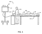
図1は、血管内処置を実行するように構成されることができるシステム100の実例である。システム100は、カテーテル102、インターフェース要素110、および処理エンジン112を含むことができる。カテーテル102は、患者118の血管に挿入されるように構成された基端104および先端106を含むことができる。示されるように、患者118は、外科用マット119を備えることができる手術台上に配置される。一例では、カテーテル102は、大腿動脈を介して患者118内に挿入され、患者118内の関心領域に案内されることができる。図1の破線は、患者118内のカテーテル102の部分を表している。いくつかの例では、カテーテル102の少なくとも一部は、止血弁などの弁109を介して患者118内に挿入される。弁109は、カテーテル102の入口位置を介して患者の身体から出る可能性のある流体量を最小化または阻止しながら、患者の血管系へのカテーテルアクセスを可能にするように構成されることができる。
FIG. 1 is an example of a
いくつかの例では、カテーテル102は、患者の血管構造内の環境を示す情報を提供するように構成された先端106にセンサ108を含むことができる。例えば、システム100がIVUSシステムである場合、センサ108は、超音波エネルギーを放射して受信して超音波データを生成するように構成された超音波トランスデューサを備えることができる。他のイメージングの例では、システム100は、OCTシステムであり、センサ108は、光を放射して受光してOCTデータを生成するように構成されたOCTトランスデューサを備えることができる。カテーテル102は、画像情報を生成し、その画像情報をイメージング処置において送信するように構成されることができる。さらなる例では、センサ108は、例えば、患者の血圧を表す信号を提供するための圧力変換器を含むことができる。
In some examples, the
図1に戻ると、血管内イメージングシステム100のインターフェース要素110は、カテーテル102と係合させることができ、電気的インターフェース、機械的インターフェースまたはその双方などのインターフェースをカテーテル102に提供することができる。いくつかの実施形態では、インターフェース要素110は、引き戻しまたは他の並進動作中に患者118内の制御された距離だけカテーテル102の少なくとも一部を並進させるように構成された並進機構を含むことができる。例えば、いくつかの実施形態では、カテーテル102は、シース内に収容されたセンサ108に取り付けられた駆動ケーブルまたはガイドワイヤを備える。いくつかのそのような構成では、インターフェース要素110は、シースを実質的に所定位置に固定したままにしながらシースを介した駆動ケーブルおよびセンサ108を並進させるように作用することができるまたは並進を容易にすることができる。
Returning to FIG. 1, the interface element 110 of the
いくつかの例では、処理エンジン112は、センサ108およびインターフェース要素110の一方または双方と通信することができる。例えば、いくつかの例では、インターフェース要素110は、処理エンジン112と通信し、カテーテル102に電気機械的インターフェースを提供する。いくつかのそのような例では、インターフェース要素110は、処理エンジン112とカテーテル102またはその要素(例えば、センサ108)との間の通信を容易にする。
In some examples, the processing engine 112 can communicate with one or both of the
いくつかの例によれば、処理エンジン112は、少なくとも1つのプログラム可能なプロセッサを備えることができる。いくつかの例では、処理エンジン112は、システムユーザ116からコマンドを受信し、および/またはユーザインターフェース120を介してカテーテル102から取得したデータを表示するように構成された1つ以上のプロセッサを含むコンピューティングマシンを備えることができる。コンピューティングマシンは、システムユーザ116からの入力を受信し、カテーテル102から受信したシステム情報および/または信号(例えば、レンダリングされた画像、データ曲線など)を出力するコンピュータ周辺機器(例えば、キーボード、マウス、電子ディスプレイ)を含むことができる。ユーザインターフェース120は、血管内イメージングシステム100の他の構成要素と通信するように構成されたソフトウェアを備えた従来のPCまたはPCインターフェースを含むことができる。いくつかの実施形態では、ユーザインターフェース120は、システム情報および/またはカテーテル102からの信号の表示(例えば、血管内画像、圧力曲線など)を表示するように構成されたディスプレイ114を含むことができる。いくつかの実施形態では、ユーザインターフェース120は、システムユーザ116からのコマンドを受信し、カテーテル102からの血管内イメージングデータを表示するように作用することができるタッチスクリーンディスプレイを含む。いくつかの例では、処理エンジン112は、1つ以上のプロセッサによって実行可能な命令またはソフトウェアを記憶するためのメモリモジュールを含むことができる。
According to some examples, the processing engine 112 can include at least one programmable processor. In some examples, the processing engine 112 includes one or more processors configured to receive commands from
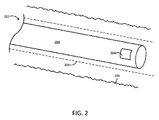
図2は、IVUSシステムで使用される例示的なカテーテルの先端の図である。図2のカテーテル202は、上述したカテーテル102と同様であってもよい。図示の実施形態では、カテーテル202は、IVUSカテーテルを備える。IVUSカテーテル202は、患者の血管234の内部構造を示す信号を生成するために超音波パルスを放射および受信するように構成されたトランスデューサなどのセンサ208を含む。いくつかの例では、センサ208は、超音波パルスを放射および受信するように構成された単一のトランスデューサ素子またはトランスデューサ素子のアレイを含むことができる。図示のように、センサ208は、患者の血管234内で先端方向または基端方向にトランスデューサを回転および/または移動させることができる駆動ケーブル268に結合される。いくつかの例では、カテーテル202は、患者の血管234内に静止したままとすることができるとともに駆動ケーブル268がシース209および血管234内のセンサ208を先端方向または基端方向に移動させるシース209を含む。
FIG. 2 is a diagram of the tip of an exemplary catheter used in an IVUS system. The catheter 202 of FIG. 2 may be similar to the
図3は、1つ以上のIVUSディスプレイが生成されることができる方法を概説するステップフロー図である。カテーテルがシステムオペレータによって患者に挿入された後、本明細書に記載されるような処理エンジンは、ステップ300において血管内イメージング機能を実行するようにコマンドを受信することができる。コマンドは、イメージング機能のパラメータおよびスケジューリングを含むことができる。ユーザは、イメージング機能を実行するように処理エンジンに命令することができる。ユーザは、イメージング機能のための所望のパラメータを手動でプログラムすることができる。
FIG. 3 is a step flow diagram outlining how one or more IVUS displays can be generated. After the catheter has been inserted into the patient by the system operator, a processing engine as described herein can receive a command to perform an intravascular imaging function in
ステップ302において、処理エンジンは、血管内イメージングカテーテルで指令されたイメージング機能を開始することができる。これは、カテーテルとのインターフェース接続、カテーテルへの制御信号および/または電力の送信、カテーテルおよび/またはカテーテル内のトランスデューサの回転、またはイメージング機能を実行するための任意の他の開始プロセスを含むことができる。いくつかの実施形態では、任意の単一のまたは組み合わせの開始プロセスは、ユーザインターフェースを介して手動で開始されることができる。例えば、イメージング機能を開始することは、トランスデューサに電気信号を導き、IVUSトランスデューサから超音波信号を放射することを含むことができる。
At
イメージング機能を開始した(例えば、ステップ302)後、ステップ304において、処理エンジンは、実行されたイメージング機能に基づいて、カテーテルから画像情報を受信することができる。画像情報は、カテーテルおよび/またはトランスデューサからの電気信号または他の信号の形態とすることができる。ステップ308において、処理エンジンは、受信した情報に基づいてディスプレイを生成することができる。ディスプレイは、システムユーザによって見ることができるディスプレイ上に提示されることができる。生成されたディスプレイは、例えば、患者内の複数の位置からの画像情報を含む長手方向画像および/または患者内の単一のトランスデューサ位置に対応する断面画像を含むことができる。いくつかのシステムでは、生成されたディスプレイは、リアルタイムで処理エンジンによって生成され、ディスプレイ上にライブ画像として示されることができる。いくつかの実施形態では、生成されたディスプレイは、ユーザによってトリガされた患者の血管構造の断面の単一のスナップショットを含むことができ、画像情報は、単一のトランスデューサ位置について一度に捕捉される。いくつかの実施形態では、様々な生成されたディスプレイが可能である。いくつかのシステムでは、ユーザは、使用されるディスプレイのモード(例えば、リアルタイム、スナップショットなど)を選択することができる。
After initiating the imaging function (eg, step 302), in
ステップ310において、処理エンジンは、受信されたコマンド(例えば、ステップ300)およびメモリに基づいて、より多くの情報が取得されるべきかどうかを判定することができる。いくつかの実施形態では、ユーザは、より多くの情報が取得されるかどうかを決定することができる。もしそうであれば、処理エンジンは、ステップ312と同様に、患者内のトランスデューサの並進を開始することができる。例えば、いくつかのシステムでは、より多くの情報が取得されるべきかどうかを判定するために、リアルタイム表示またはスナップショット表示などの選択されたディスプレイモードがステップ310において使用されることができる。
At
いくつかの実施形態では、血管内イメージングシステムは、並進機構を備える。並進機構は、モータおよび/または手動操作による自動並進のために構成されることができる。いくつかのそのような実施形態では、ステップ312において、処理エンジンは、並進機構とインターフェース接続し、モータを介して直接並進を開始することができる。血管内イメージングシステムのいくつかの実施形態は、トランスデューサの手動並進のために構成されている。そのような実施形態では、処理エンジンは、トランスデューサを並進するようにユーザに促すことができる。
In some embodiments, the intravascular imaging system comprises a translational mechanism. The translation mechanism can be configured for automatic translation by motor and / or manual operation. In some such embodiments, in
トランスデューサが並進された後、ステップ302が繰り返され、イメージング機能が再び開始されることができる。プロセスは、追加の画像情報が患者内の異なる位置で取得されることができるように繰り返されてもよい。ステップ310において、追加の情報が取得されないと判定されると、ステップ314において、生成されたディスプレイまたは他の関連する画像情報がメモリに保存されることができる。いくつかの実施形態では、ユーザは、手動で情報をメモリに保存することができる。追加的にまたは代替的に、システムは、システム動作に関連する1つ以上の情報片を自動的に保存することができる。カテーテルを利用する全ての操作が完了している場合、様々な実施形態では、ステップ316において、カテーテルは、手動または自動のいずれかで患者から引き出されることができる。
After the transducer is translated, step 302 can be repeated and the imaging function can be started again. The process may be repeated so that additional imaging information can be obtained at different locations within the patient. If it is determined in
上述のように、いくつかの例では、トランスデューサは、患者内の複数の位置から画像データを取得するために患者内で移動される。いくつかの実施形態では、トランスデューサは、手動で、または並進機構の助けを借りて再配置されることができる。いくつかの例では、そのような並進機構は、ユーザが所望の距離、所望の方向、および所望の速度のいずれか1つでトランスデューサを手動で移動するのを支援することができる。追加的または代替的に、並進機構は、患者内でトランスデューサを動かすことができるモータを含むことができる。モータは、処理エンジンからのプログラム命令にしたがって、手動または自動で制御されることができる。例示的な並進機構は、本出願の譲受人に譲渡され、その全体が参照することによって本明細書に組み込まれる、2013年5月14日に出願された、「装置係合を監視するためのシステムおよび方法」と題された米国特許出願第13/894,045号においてさらに記載される。 As mentioned above, in some examples, the transducer is moved within the patient to obtain image data from multiple locations within the patient. In some embodiments, the transducer can be rearranged manually or with the help of translational mechanisms. In some examples, such translational mechanisms can assist the user in manually moving the transducer at any one of the desired distance, desired direction, and desired speed. Additional or alternative, the translational mechanism can include a motor capable of moving the transducer within the patient. The motor can be controlled manually or automatically according to program instructions from the processing engine. An exemplary translational mechanism is transferred to the assignee of the present application and is incorporated herein by reference in its entirety, filed May 14, 2013, "for monitoring device engagement. Further described in US Patent Application No. 13 / 894,045 entitled "Systems and Methods".
追加の画像情報の取得のためにトランスデューサが異なる位置に移動されるいくつかの実施形態では、処理エンジンは、ステップ306のように位置センサから位置情報をさらに受信することができる。位置情報は、関連付けられた画像情報とともにメモリに表示および/または保存されることができる。様々な例において、ステップ304におけるような画像情報の受信およびステップ306におけるような位置情報の受信は、位置センサの可動要素の任意数の異なる位置から任意数の組の画像および位置情報を受信することを含むことができる。いくつかの実施形態では、ステップ304におけるような画像情報の受信およびステップ306におけるような位置情報の受信は、第1および第2の位置が互いに異なるように、トランスデューサの第1の位置に対応する第1の組の画像および位置情報ならびにトランスデューサの第2の位置に対応する第2の組の画像および位置情報の受信を含むことができる。
In some embodiments where the transducer is moved to a different position to obtain additional image information, the processing engine can further receive position information from the position sensor as in
いくつかの例では、位置情報は、位置センサによって生成されることができる。例示的な位置情報は、位置センサの基準要素と位置センサの可動要素との相対位置に関する情報を備えることができる。いくつかの構成では、位置センサの基準要素および可動要素のうちの1つの位置は、トランスデューサの位置に対応する。したがって、位置センサの要素の相対運動は、患者内のトランスデューサの相対運動に対応することができる。 In some examples, the position information can be generated by the position sensor. The exemplary position information can include information about the relative position of the reference element of the position sensor and the movable element of the position sensor. In some configurations, the position of one of the reference and movable elements of the position sensor corresponds to the position of the transducer. Therefore, the relative movement of the elements of the position sensor can correspond to the relative movement of the transducer in the patient.
いくつかの実施形態では、位置センサの可動要素の位置が患者の血管構造におけるトランスデューサの位置と相関することから、受信された画像および位置情報の組は、トランスデューサの異なる位置に対応することができる。いくつかの実施形態では、画像および位置情報が受信される可動要素の位置のいずれかにおいて、画像および位置情報は、共通のトランスデューサ位置で受信されると互いに関連付けられることができる。各組の画像情報は、患者の血管構造内の固有の位置から生成された画像情報に対応することができる。位置情報の組は、固有の位置間の空間的関係に関する詳細を提供することができる。これは、複数の可動要素の位置からの画像および位置情報の組み合わせと、組み合わせられた画像の構築を可能にする。 In some embodiments, the position of the moving element of the position sensor correlates with the position of the transducer in the patient's vascular structure, so that the received image and position information set can correspond to different positions of the transducer. .. In some embodiments, at any of the positions of the moving elements where the image and position information are received, the image and position information can be associated with each other when received at a common transducer position. Each set of image information can correspond to image information generated from a unique position in the patient's vascular structure. A set of location information can provide details about the spatial relationship between unique locations. This allows the combination of images and position information from the positions of multiple moving elements and the construction of combined images.
いくつかの実施形態では、画像および位置情報は、引き戻し操作(例えば、全て患者の血管内の関心領域を横切って)を実行することによって一連のトランスデューサ位置から受信される。引き戻しは、カテーテルを患者の血管構造内に挿入することと、患者を介してトランスデューサを後退しながらイメージング機能を実行することによって複数のトランスデューサ位置に対応する画像および位置情報を取得することとを備えることができる。引き戻しは、モータによって実行されることができ、血管内処理エンジンのユーザインターフェースを介してユーザによって開始されることができる。所定の引き戻し操作が実行されることができ、モータは、トランスデューサを所定の方法で引き戻す。いくつかの実施形態では、ユーザは、手動でモータの動作を制御し、引き戻し動作を制御することができる。モータ制御された引き戻しは、メモリに記憶されたイメージングスケジュールの一部として自動的に実行されることができる。自動引き戻しは、位置センサから血管内処理エンジンへ位置情報を提供するように構成されたフィードバック要素を含むことができ、血管内処理エンジンは、位置情報に基づいてモータを制御することができる。いくつかの構成では、引き戻しは、完全に手動で実行されることができ、ユーザは、イメージング機能を実行しながら患者内のトランスデューサを手動で並進する。引き戻しイメージング動作の実行は、位置情報の組間の相対的な空間的関係が分かっている複数組の位置および対応する画像情報をもたらすことができる。 In some embodiments, the image and location information is received from a series of transducer positions by performing a pullback operation (eg, all across the area of interest within the patient's blood vessels). Pullback comprises inserting a catheter into the patient's vascular structure and acquiring images and position information corresponding to multiple transducer positions by performing imaging functions while retracting the transducer through the patient. be able to. The pullback can be performed by a motor and can be initiated by the user via the user interface of the endovascular processing engine. A predetermined pullback operation can be performed and the motor pulls the transducer back in a predetermined way. In some embodiments, the user can manually control the operation of the motor and control the pullback operation. Motor-controlled pullbacks can be performed automatically as part of a memory-stored imaging schedule. The automatic pullback can include a feedback element configured to provide position information from the position sensor to the endovascular processing engine, which can control the motor based on the position information. In some configurations, pullback can be performed completely manually and the user manually translates the transducer in the patient while performing the imaging function. Performing a pullback imaging operation can result in multiple sets of positions and corresponding image information for which the relative spatial relationships between the sets of position information are known.
複数の可動要素の位置(複数のトランスデューサ位置に関連する)からの画像および位置情報は、3次元ボリュームの画像情報を生成するために組み合わせられることができる。受信した位置および画像情報の各組の相対的なトランスデューサの位置が分かっている場合、画像情報の各組は、適切な順序で適切な空間的な分離をもって配置されることができる。いくつかの実施形態では、血管内処理エンジンによって受信される画像データの単一の組は、トランスデューサに近接する患者の血管系の断面画像を含む。位置情報の単一の組は、患者の血管系内のトランスデューサの相対的な長手方向の位置を含むことができる。第2の位置から受信した画像および位置情報の第2の組は、第2の断面画像と、画像が撮像されたときのトランスデューサの相対的な長手方向の位置とを含むことができる。第1および第2のトランスデューサの位置の間の相対的関係は、第1および第2の位置情報の組によって判定されることができる。したがって、第1および第2の組の画像情報は、既知の距離だけ離れた長手方向の位置で撮像された断面画像を表すことができる。断面は、長手方向軸に沿って組み合わせられ、2組の情報の3次元表現を形成するように適切に離間されている。 Images and position information from the positions of the plurality of moving elements (related to the positions of the plurality of transducers) can be combined to generate the image information of the three-dimensional volume. If the position received and the relative position of the transducer in each set of image information are known, then each set of image information can be placed in the proper order and with the proper spatial separation. In some embodiments, a single set of image data received by the endovascular processing engine comprises a cross-sectional image of the patient's vascular system in close proximity to the transducer. A single set of position information can include the relative longitudinal position of the transducer in the patient's vascular system. A second set of images and position information received from the second position can include a second cross-sectional image and the relative longitudinal position of the transducer when the image was taken. The relative relationship between the positions of the first and second transducers can be determined by the set of first and second position information. Therefore, the first and second sets of image information can represent cross-sectional images taken at longitudinal positions separated by a known distance. The cross sections are combined along the longitudinal axis and appropriately spaced to form a three-dimensional representation of the two sets of information.
一般に、任意数の組の画像および位置情報(すなわち、固有の断面)は、このように患者の血管系などのトランスデューサの周囲の3次元表現を構築するように組み合わせられることができる。そのような表現は、長手方向画像と呼ぶことができる。図4は、血管内イメージングシステムの実施形態によって構築されることができる例示的な長手方向画像を示している。図4は、例えば、図1のディスプレイ114上に示されることができるようなディスプレイ420を示している。再び図4を参照すると、ディスプレイ420は、特定のトランスデューサ位置に対応する画像情報422の組を表示するように構成された断面画像424を含むことができる。ディスプレイ420は、それぞれが特定のトランスデューサ(例えば、センサ108)の位置からの関連する位置情報にしたがって配置された一連の画像情報の長手方向配置を示すように構成された長手方向画像426を含むことができる。長手方向画像426は、長手方向軸が患者の体内のトランスデューサの並進方向を表すようなものとすることができる。したがって、長手方向画像426の水平軸に沿った各データポイントは、対応する断面画像424と関連付けられることができる。なお、図4は、トランスデューサの動きを表す軸が水平軸であることを示しているが、そのような特性は、代替的に垂直軸または任意の他の方向を表すことができ、いくつかの実施形態では、一般に長手方向軸とすることができる。いくつかの実施形態では、長手方向画像426は、本質的に、互いに積み重ねられ且つそれらの相対位置にしたがって配置された複数の断面画像の側面図である。いくつかの実施形態では、断面画像のそれぞれは、画像情報が受信されたトランスデューサ位置の間の間隙を埋めるために使用されることができる少量の長手方向情報を含むことができる。
In general, any set of images and location information (ie, a unique cross section) can be combined in this way to construct a three-dimensional representation around the transducer, such as the patient's vascular system. Such a representation can be referred to as a longitudinal image. FIG. 4 shows an exemplary longitudinal image that can be constructed by an embodiment of an intravascular imaging system. FIG. 4 shows, for example, a
図4に示されるディスプレイ420は、画像データ428を含むことができる。画像データ428は、断面画像424、長手方向画像426、イメージングされる患者、他のシステム情報などに関する様々な情報片を含むことができる。いくつかの例では、画像データ428は、患者名、患者ID番号、日時、フレーム番号、および/またはイメージング周波数などの画像情報取得パラメータを含むことができる。様々な実施形態において、画像データ428は、ディスプレイ420上の単一の位置にまとめて表示されることができ、または様々な位置に表示されることができる。図4の例では、画像データ428は、複数の位置に配置される。いくつかの実施形態では、ディスプレイ420は、1つ以上のイメージング機能を連続的に実行しながらリアルタイム表示を含むことができる。ディスプレイ420は、コマンドおよび制御機能をユーザに提供するためのユーザインターフェース430を含むことができる。
The
いくつかの実施形態では、図4に示されるディスプレイ420は、血管内処理エンジンの一部である。ディスプレイ420は、ユーザ入力および操作のためのタッチスクリーンを備えることができる。いくつかの実施形態では、ユーザは、生成されたディスプレイ420に関して様々な機能を実行することができる。いくつかの例では、ユーザは、ディスプレイ420の輝度および/またはコントラストを操作し、スクリーンショットをメモリに保存し、引き戻し動作などのイメージング機能を開始し、イメージング機能を終了させるなどすることができる。長手方向画像426の場合、いくつかの実施形態では、ユーザは、対応するトランスデューサ位置の関連する断面画像424を表示するために、長手方向画像426内の長手方向軸に沿った点を選択することができる。
In some embodiments, the
位置センサを含む例示的な血管内システムおよび方法は、本出願の譲受人に譲渡され、その全体が参照することによって本明細書に組み込まれる、2013年12月30日に出願された、「血管内イメージングにおける位置検知」と題された米国特許出願第14/143,801号に記載されている。 Exemplary intravascular systems and methods, including position sensors, are transferred to the assignee of this application, which is incorporated herein by reference in its entirety, filed December 30, 2013, "Vascular. It is described in US Patent Application No. 14 / 143,801 entitled "Position Detection in Internal Imaging".
図1に示されるシステム100などの他の例示的なシステムは、MPSシステムを含むことができる。図5Aは、センサ送達装置510を含む例示的なMPSシステムである。図5AのMPSシステムは、医療用ガイドワイヤ530を摺動可能に受け入れるためのガイドワイヤ管腔522を有する先端スリーブ520を含む。センサ508は、先端スリーブ520に結合されており、センサ508は、患者の生理学的パラメータを検知および/または測定し、生理学的パラメータを表す信号を生成することができる。したがって、先端スリーブ520、ひいてはセンサ508は、先端スリーブ520を医療用ガイドワイヤ530の上法を所望の位置まで摺動させることによって患者内(例えば、静脈、動脈、または他の血管内などの患者の解剖学的構造内、または心臓弁を横切って)に配置されることができる。
Other exemplary systems, such as the
図5Aのセンサ送達装置510はまた、先端スリーブ520に連結される基端部550を含む。基端部550は、センサ508からの信号を患者外の位置(例えば、図1の処理エンジン112もしくはディスプレイ114、または他のコンピュータ、モニタ、または他の医療器具)に通信するための通信チャネル560を含む。通信チャネル560は、センサ508が光ファイバ圧力センサである場合など、特定の好ましい実施形態では、光ファイバ通信チャネルを備えることができる。あるいは、通信チャネル560は、1つ以上の導電性ワイヤなどの導電性媒体を備えることができる。もちろん、通信媒体の他の多くの形態は、センサ508によって生成された信号を患者外の場所に送信するのに適することができる。本発明のいくつかの実施形態では、通信チャネル560は、可能な例として、無線通信リンク、赤外線機能、または超音波などの音響通信などの様々な流体および/または非流体通信媒体のいずれかを備えることができる。
The
例示的なMPSシステムの動作中、基端部550はまた、先端スリーブ520およびセンサ508を患者の解剖学的構造(例えば血管)内に配置する際にオペレータ(例えば、医師または他の医療スタッフ)を支援するように構成される。これは、典型的には、オペレータが最初に「標準的な」医療用ガイドワイヤ530を患者の血管構造に挿入し、関心領域を越えてそれを前進させることによって達成される。そして、センサ送達装置510は、管腔522がガイドワイヤ530上を摺動するように、先端スリーブ520をガイドワイヤ530に「ねじ込む」ことによって展開され、センサ508が所望の位置に来るまで基端部550を移動させる(例えば、押すまたは引っ張る)ことによって先端スリーブ520(および関連するセンサ508)を前進させる。
During the operation of an exemplary MPS system, the
装置510およびガイドワイヤ530は、典型的には、関心のある解剖学的構造(例えば、血管)に配置されたガイドカテーテル502の内部で操作される。本発明の特定の好ましい実施形態では、ガイドワイヤ管腔522は、「標準的な」サイズの医療用ガイドワイヤ上を摺動するようなサイズにすることができる。例えば、多くの製造業者は、外径が約0.014インチ未満から外径が約0.038インチを超える範囲の、典型的にはこの範囲内の有限数の一般的なサイズを有する医療用ガイドワイヤを製造している。「標準的な」サイズの医療用ガイドワイヤは、例えば、0.010、0.014、0.018、0.021、0.025、0.028、0.032、0.035、0.038インチの外径を有することができる。したがって、本発明の特定の好ましい実施形態では、ガイドワイヤ管腔522は、特定の標準サイズの医療用ガイドワイヤ上を摺動するように適切にサイズ決めされることができる。したがって、本発明の好ましい実施形態にかかる装置は、標準的な医療用ガイドワイヤサイズに対応するサイズの範囲で利用可能にすることができる。
The
本発明の実施形態にかかるセンサ送達装置510の1つの潜在的な利点は、医師がそれらの選択したガイドワイヤを使用することができることである。センサ送達装置510は、任意のガイドワイヤとともに使用されるようにサイズ決めされることができる。医師は、例えば、特定の処置のための独特な屈曲およびトルク特性に基づいて、特定のガイドワイヤを選択することができる。本発明の様々な実施形態にかかる送達装置510は、特定の用途に最も適していると考えられるガイドワイヤを使用する能力を医師に提供する。
One potential advantage of the
センサ送達装置510の他の潜在的な利点は、センサ読み取りを行うためにガイドワイヤの再配置を必要としないことである。例えば、ガイドワイヤが狭窄病変にわたって配置されると、センサ送達装置510は、ガイドワイヤ上に配置される(例えば、前進および/または後退される)ことができ、したがって、センサ508は、例えば、ガイドワイヤを動かすことなく、圧力読み取りを行うために病変にわたって前進および後退されることができる。医師はまた、そのような測定を行うために、病変または複数の病変にわたってガイドワイヤを再配置する必要がないことによって時間を節約することもできる。
Another potential advantage of the
図5Aに示される例では、関心のある血管構造(この例では、患者の冠状動脈とすることができる血管534)内に配置されたガイドカテーテル502を使用して装置510が展開されている。本発明の特定の実施形態では、装置510のサイズまたは「フットプリント」(例えば、幅および/または断面積)は、特定の標準サイズのガイドカテーテル内に適合させることができる。例えば、特定の診断用途では、特定のサイズのガイドカテーテル(例えば、約5または5フレンチ(FR)よりも小さい)内に装置510が展開されることが望ましい。
In the example shown in FIG. 5A, the
本発明の特定の実施形態では、装置の先端スリーブ520は、ガイドワイヤ530と略同心であってもよい。基端部550を先端スリーブ520に連結することは、ガイドワイヤ530を(例えば、「モノレール」カテーテル構成と呼ばれることもある)装置510の残りから分離することができ、これは、典型的には、ガイドカテーテル502の内部で生じる。ガイドワイヤ530および装置510は、双方とも、別個の装置として、ガイドカテーテル502の基端で患者を出る。装置510およびガイドワイヤ530を分離させることは、医師が必要に応じて装置510およびガイドワイヤ530を独立して制御するのを可能にする。医師は、カテーテル交換のためにより短いガイドワイヤを使用することもできる。例えば、モノレール型構成は、約170から200cmの長さのガイドワイヤの使用を可能にするが、「オーバー・ザ・ワイヤ」構成は、はるかに長い(例えば、最大500cmまたはそれ以上)のガイドワイヤの使用を必要とすることができる。装置510とガイドワイヤ530とを(先端スリーブ520を除いて)分離させることはまた、装置510とガイドワイヤ530とを一体として移動させなければならない場合よりも(例えば、ガイドカテーテル502内での)摩擦を少なくする。いくつかの実施形態では、親水性コーティングは、例えば装置510を前進または後退させるときに遭遇する摩擦量をさらに低減するために、装置の様々な部分に適用されることができる。
In certain embodiments of the invention, the
本発明の様々な実施形態がうまく適合し得る1つの診断用途は、血流予備量比(FFR)の測定である。上述のように、FFR測定は、狭窄病変が例えば血管を通る流れを妨げる程度を定量化する。所与の狭窄に対してFFRを計算するために、以下の2つの血圧測定が必要とされる:一方の圧力読み取りは、狭窄部の先端側(下流側)で行われ、他方の圧力読み取りは、狭窄部の基端側(上流側)で行われる。したがって、FFRは、先端圧力と基端圧力との無単位の比である。狭窄病変にわたる圧力勾配は、狭窄の重症度の指標である。狭窄がより限定的であるほど、圧力降下はより大きくなり、FFRが低下する。 One diagnostic application to which the various embodiments of the invention may fit well is the measurement of blood flow reserve ratio (FFR). As mentioned above, FFR measurements quantify the extent to which stenotic lesions impede flow through, for example, blood vessels. Two blood pressure measurements are required to calculate the FFR for a given stenosis: one pressure reading is done on the distal side (downstream side) of the stenosis and the other pressure reading , It is performed on the proximal side (upstream side) of the stenosis. Therefore, FFR is a unitless ratio of tip pressure to base pressure. The pressure gradient over the stenotic lesion is an indicator of the severity of the stenosis. The more limited the stenosis, the greater the pressure drop and the lower the FFR.
図5Bは、本発明の実施形態にかかる患者の生理学的パラメータを測定するためのセンサ送達装置の斜視図である。図5Bに示される実施形態は、例えば、患者の血管内でFFR測定を行うために配置されてもよい。図5Bは、狭窄(例えば、狭窄病変536b)にわたって患者の血管(例えば、冠動脈534b)内に展開されるセンサ送達装置510bを示している。例えば、FFR測定を行うために、第1のセンサ540bは、関心のある位置(例えば、狭窄病変536b)の下流の位置531bで先端(下流)血圧Pdを測定するように配置されてもよい。そして、第1のセンサ540bは、関心のある位置(例えば、狭窄病変536b)の上流の位置533bで基端(上流)血圧Ppを測定するように配置されることができる。FFRは、単に先端圧力対基端圧力の比、またはFFR=(Pd/Pp)として計算される。用語「下流」および「上流」の使用は、図5Bに示されるように、血流の法線方向「D」に関するものである。
FIG. 5B is a perspective view of a sensor delivery device for measuring patient physiological parameters according to an embodiment of the present invention. The embodiment shown in FIG. 5B may be arranged, for example, to make FFR measurements within the patient's blood vessels. FIG. 5B shows a
図5Bにおいて、第1のセンサ540bは、先端スリーブ520bに結合される。図5Bに示される実施形態では、第1のセンサ540bは、先端スリーブ520bの外面に結合される。第1のセンサ540bは、血液パラメータ(例えば、血圧、温度、pH、血液酸素飽和度など)などの患者の生理学的パラメータを測定し、生理学的パラメータを表す信号を生成するように構成される。本発明の特定の好ましい実施形態では、第1のセンサ540bは、血圧を測定するように適合された光ファイバ圧力センサである。光ファイバ圧力センサの例は、市販のセンサであるファブリペロー光ファイバ圧力センサである。ファブリペロー光ファイバセンサの例は、Opsens(Quebec、Canada)製の「OPP−M」MEMSベースの光ファイバ圧力センサ(400ミクロンサイズ)であり、製造された「FOP−MIV」センサ(515ミクロンサイズ)Fiso Technologies、Inc.(ケベック、カナダ)。特定の代替実施形態では、第1のセンサ540bは、ピエゾ抵抗圧力センサ(例えば、MEMSピエゾ抵抗圧力センサ)であってもよく、他の実施形態では、第1のセンサ540bは、容量性圧力センサ(例えば、MEMS容量性圧力センサ)であってもよい。例えば、センサ540bで最も生理学的な測定を行うためには、(大気圧に対して)約−50mmHgから約+300mmHgの圧力検知範囲が望ましい。
In FIG. 5B, the
ファブリペロー光ファイバ圧力センサをセンサ540bとして使用する本発明の実施形態では、そのようなセンサは、ダイアフラムに対する圧力に応じてキャビティ長測定を変化させる反射ダイアフラムを有することによって機能する。光源からのコヒーレント光は、ファイバを伝播し、センサ端で小さなキャビティを横切る。反射ダイアフラムは、光信号の一部をファイバに戻して反射する。反射された光は、ファイバを通ってファイバの光源端部の検出器に戻る。2つの光波、すなわち光源光と反射光は、反対方向に進み、互いに干渉する。干渉量は、キャビティ長によって異なる。キャビティ長は、ダイアフラムが圧力を受けて撓むと変化する。干渉量は、干渉縞検出器によって記録される。
In an embodiment of the invention using a Fabric Perot fiber optic pressure sensor as the
図5Bは、先端スリーブ520bに連結された基端部550bを示している。基端部550bは、センサ540bから生理学的信号を患者外の位置(例えば、プロセッサ、ディスプレイ、コンピュータ、モニタ、または他の医療装置)に伝達するための通信チャネル560bを含む。基端部550bは、好ましくは、先端スリーブ520bおよびセンサ540bを患者の解剖学的構造(例えば、血管)内に配置する際にオペレータ(例えば、医師または他の医療スタッフ)を支援するために十分な剛性の材料から形成されることができる。
FIG. 5B shows a base end portion 550b connected to a
基端部550bのための1つの適切な材料は、例えば、ステンレス鋼のハイポチューブであってもよい。用途に応じて、基端部550b(「送達管」とも呼ばれる)は、典型的には、患者内の関心のある生理学的位置に装置を押す、引っ張るおよび操作するための妥当な量の制御を提供するために先端スリーブ520bよりも堅く剛性がなければならない。介入心臓処置において、例えば、基端部550bの少なくとも一部は、大動脈内に配置された誘導カテーテル内で操作される。したがって、そのような用途の基端部550bは、大動脈のアーチを収容するのに十分なほど柔軟でなければならないが、装置を押したり引っ張ったりするのに十分な剛性を有するべきである。したがって、基端部550bに適した材料はまた、例えば、ニチノール、ナイロン、およびプラスチックなどの材料、または複数の材料の複合材料を含むことができる(前述したステンレス鋼ハイポチューブに加えて)。
One suitable material for the base end 550b may be, for example, a stainless steel hypotube. Depending on the application, the proximal 550b (also referred to as the "delivery tube") typically provides a reasonable amount of control for pushing, pulling and manipulating the device to the physiological position of interest within the patient. Must be stiffer and more rigid than the
通信チャネル560bは、図5Bに示すように、基端部550bの外面に沿って配置されてもよく、または基端部550b内に形成されてもよい。例えば、通信チャネル560bは、いくつかの実施形態において、基端部550bを通って長手方向に延びる通信用管腔を備えることができる。通信チャネル560bは、特定の実施形態では、センサ540bが光ファイバ圧力センサである場合など、光ファイバ通信チャネルを備えてもよい。あるいは、通信チャネル560bは、導電性ワイヤなどの導電性媒体、またはセンサ540bによって生成された信号を送信するのに適した他の通信媒体を含むことができる。本発明の好ましい実施形態では、通信チャネル560bは、非流体通信媒体を含む。図5Bに示される実施形態では、通信チャネル560b(例えば、光ファイバケーブル)は、基端部550bを超えて先端方向に延び、センサ540bに結合される。そのような実施形態の通信チャネル560bは、基端部550b(例えば、ステンレス鋼ハイポチューブ)の通信管腔内に少なくとも部分的に収容される。
The
図5Bはまた、第2のセンサ542bが装置510bに結合されることができる本発明の任意の実施形態を示している。例えば、第2のセンサ542bは、第1および第2のセンサ540b、542bが狭窄病変をまたぐように十分に離間されている(例えば、固定距離離れている)ように、基端部550bに結合されることができる。この実施形態は、第1のセンサ540bが狭窄病変536bの先端に配置されてPdを測定することができ且つ第2のセンサ542bが狭窄病変536bの基端に配置されてPpを測定することができるため、装置510bを再配置する必要なくFFRを測定する能力を提供することができる。第2のセンサ542bは、例えば、図5Bに示すように、基端部550b内に収容されることができるかまたは基端部550bの外面に沿って配置されることができる通信チャネル562bを有することができる。さらに、PdおよびPpを実質的に同時に測定する能力は、精度を改善することができ、および/または、本出願の譲受人に譲渡され、その全体が参照することによって本明細書に組み込まれる、2009年9月11日に出願された、「生理学的センサ送達装置および方法」と題された米国特許第8,298,156号明細書に図示されて記載された特定の種類のエラーの影響を低減することができる。
FIG. 5B also shows any embodiment of the invention in which the second sensor 542b can be coupled to the
特定の実施形態は、3つ以上のセンサを有することができ、そのような実施形態における隣接するセンサ間の間隔は、可変のスペーシング能力を提供するように変更されることができることに留意すべきである。本発明の特定の代替実施形態では、例えば、先端スリーブ520b上にセンサが配置されていない状態で、1つ以上のセンサが基端部550bに配置されることができる。いくつかの代替実施形態では、基端部550bに沿って既知の固定距離だけ間隔を置いて配置された複数のセンサ(2つまたは3つまたは4つ以上のセンサ)を有することが望ましい場合がある。これは、例えば、PdおよびPp信号を取得するためにそこから病変部にわたって配置された(複数のセンサのうちから)センサの適切な対を選択することにより、病変長にかかわらず略同時にPdおよびPpを測定する能力を提供することができる。さらに、センサは、生理学的パラメータ(例えば、PdおよびPp)の測定と併せて病変サイズの視覚的評価を提供することができる何らかの形態の放射線不透過性マーキング(例えば、マーカーバンド)を組み込むことができる。
Note that certain embodiments may have three or more sensors and the spacing between adjacent sensors in such embodiments may be modified to provide variable spacing capabilities. Should be. In a particular alternative embodiment of the invention, for example, one or more sensors can be placed at the proximal end 550b without the sensors being placed on the
様々な実施形態において、装置(例えば、510、510b)は、上述したものを含む任意の適切な材料から製造されることができる。いくつかの例では、装置(またはその一部)は、磁化可能な材料から製造される。例えば、基端部(例えば、250、250b)および先端スリーブ(例えば、520、520b)などの装置の1つ以上の部分は、磁化可能な鋼(例えば、冷間加工されたステンレス鋼)から製造されてもよい。そのような磁化可能な材料は、装置によって担持されるセンサおよび/または装置が並進するガイドワイヤによって担持されるセンサを使用して判定される圧力勾配曲線に割り当てることができる距離スケールを開発するために有用であり得る。 In various embodiments, the device (eg, 510, 510b) can be made from any suitable material, including those described above. In some examples, the device (or part thereof) is made from a magnetizable material. For example, one or more parts of the device, such as the base end (eg, 250, 250b) and the tip sleeve (eg, 520, 520b), are made from magnetizable steel (eg, cold-worked stainless steel). May be done. To develop a distance scale such a magnetizable material can be assigned to a pressure gradient curve determined using a sensor carried by the device and / or a sensor carried by a guide wire that translates the device. Can be useful for.
本明細書に記載の装置および/または方法を用いて生理学的パラメータ測定が容易にされることができる他の用途があることが理解されるべきである。様々な例示的なMPSシステムの他の可能な実施形態および実装は、米国特許第8,298,156号明細書(上記参照)に記載されている。 It should be understood that there are other applications in which physiological parameter measurements can be facilitated using the devices and / or methods described herein. Other possible embodiments and implementations of various exemplary MPS systems are described in US Pat. No. 8,298,156 (see above).
図6は、図5Aおよび図5Bに示されるようなMPSシステムの例示的な動作を示すプロセスフロー図である。図6に示される動作の順序は、例示的な目的のみのものである。いくつかの実施形態では、動力注入システムまたは診断監視システムなどのシステムは、本方法が制御パネル(または利用可能であれば2次パネル)上で手動起動を開始するようにオペレータが要求した後、自動的にまたは代替的に、図6に示される方法のステップのいくつかを実行することができる。 FIG. 6 is a process flow diagram illustrating exemplary operation of an MPS system as shown in FIGS. 5A and 5B. The sequence of operations shown in FIG. 6 is for illustrative purposes only. In some embodiments, a system such as a power injection system or diagnostic monitoring system is used after the operator requests that the method initiate a manual activation on the control panel (or secondary panel if available). Automatically or alternatively, some of the steps in the method shown in FIG. 6 can be performed.
図6のステップ600は、例えば、狭窄病変などの関心のある位置に、または心臓弁を横切って患者内にガイドワイヤを配置することを含む。いくつかの実施形態では、これは、診断用ガイドワイヤであってもよく、ガイドカテーテルはまた、ガイドワイヤとともに患者に挿入されてもよい。ステップ602は、センサが関心のある位置の上流に(例えば、狭窄病変の上流または弁の高圧側に)配置されるように、ガイドワイヤ上にセンサ送達装置を配置することを備える。いくつかの実施形態では、センサ送達装置は、ガイドワイヤ上を摺動する先端スリーブに取り付けられたセンサと、ガイドワイヤを移動させる必要なくガイドワイヤを介して先端スリーブを所望の位置に前進させるためにオペレータによって使用される基端部とを有する。ステップ604は、関心のある位置の上流の生理学的パラメータの値を測定するためにセンサ送達装置のセンサを使用することを備える。いくつかの実施形態では、生理学的パラメータは血圧であり、狭窄病変部の上流のセンサによって測定された圧力は基端圧力Ppである。 Step 600 of FIG. 6 involves placing a guide wire within the patient at a location of interest, such as, for example, a stenotic lesion, or across a heart valve. In some embodiments, this may be a diagnostic guidewire, and the guide catheter may also be inserted into the patient with the guidewire. Step 602 comprises placing the sensor delivery device on the guide wire so that the sensor is placed upstream of the location of interest (eg, upstream of the stenotic lesion or on the high pressure side of the valve). In some embodiments, the sensor delivery device is for advancing the sensor attached to the tip sleeve that slides over the guide wire and the tip sleeve through the guide wire to a desired position without the need to move the guide wire. Has a proximal end used by the operator. Step 604 comprises using the sensor of the sensor delivery device to measure the values of physiological parameters upstream of the location of interest. In some embodiments, the physiological parameter is blood pressure and the pressure measured by a sensor upstream of the stenotic lesion is proximal pressure Pp.
いくつかの例では、ステップ604で行われたものなどのPp測定値は、独立したソースから得られた測定値に正規化されることができる。Pp測定値を「正規化する」とは、センサ送達装置のセンサで測定されたPd値(例えば、下流側圧力)との後の比較または計算に使用されるPp値を得るために独立したソース(例えば、処置中に患者の血圧を監視する流体センサ)が使用されるという事実を指す。正規化ステップは、基本的には、後続の下流圧力測定(例えば、Pd)が行われるときにエラーが導入されていない(または任意のエラーが最小となる)ように、センサを用いて測定されたPp値が独立したソースを使用して測定されたPp値に等しいことを保証する。必要に応じて、Pp値に調整されることができるが、センサベースのPp値を独立したソースのPp値に合わせるように調整する方が大抵の場合に簡単であり得る。
In some examples, Pp measurements, such as those made in
ステップ606は、センサが関心のある位置の下流(例えば、狭窄病変の下流)にあるように、センサ送達装置をガイドワイヤ上に再配置することを備える。ステップ608は、生理学的パラメータの下流の値を測定するためにセンサ送達装置のセンサを使用することを備える。いくつかの実施形態では、このステップは、狭窄病変の下流の血圧Pdを測定することを備える。ステップ610は、関心のある位置の下流の測定値(例えば、Pd、下流の血圧)を、独立したソースを使用して関心のある位置の上流で測定された値(例えば、Pp)と比較することを備える。いくつかの実施形態では、ステップ610で行われる比較は、2つの測定値の比を計算することを備えることができる。本発明のいくつかの実施形態では、ステップ610は、下流の血圧と上流の血圧の比Pd/PpとしてFFRを計算することを備える。オプションのステップであってもよいステップ612は、ステップ610で行われた比較の結果の表示を提供することを備える。例えば、ステップ612は、計算されたFFR値の表示(例えば、数値またはグラフィック表示またはプロット)を提供すること、および/または他のキューがオペレータに提供されることができることを備えることができる。狭窄病変の重症度の色分けされた表示は、例えば、0.75未満のFFR値については赤色指標、および/または0.75以上のFFR値については緑色指標が提供されることができる。非視覚的指標を含む他の指標の例が可能である−例えばアラーム音などの可聴指標は、0.75未満のFFR値をオペレータに警告することができ、オペレータに治療決定を促すことができる。
Step 606 comprises rearranging the sensor delivery device on the guide wire so that the sensor is downstream of the location of interest (eg, downstream of the stenotic lesion). Step 608 comprises using the sensor of the sensor delivery device to measure downstream values of physiological parameters. In some embodiments, this step comprises measuring the blood pressure Pd downstream of the stenotic lesion. Step 610 compares the downstream measurements of the location of interest (eg, Pd, downstream blood pressure) with the values measured upstream of the location of interest using an independent source (eg, Pp). Be prepared for that. In some embodiments, the comparison made in
上述した例示的なIVUSシステムおよび方法と同様に、MPS処置は、患者内のセンサの位置に関連する位置情報を取得することを含むことができる。例えば、位置情報は、患者もしくは患者内の病変に対するセンサの位置を示すことができ、または上流および下流測定値の間の相対的位置差を示す相対位置情報を含むことができる。様々な例において、例えば可動要素および基準要素を含むIVUSシステムに関して上述したような位置センサが使用されてもよい。可動要素は、センサが患者内を移動するときに基準要素に対して移動するように構成されてもよい。 Similar to the exemplary IVUS systems and methods described above, MPS treatment can include acquiring location information related to the location of the sensor within the patient. For example, the location information can indicate the location of the sensor with respect to the patient or lesion within the patient, or can include relative location information indicating the relative position difference between upstream and downstream measurements. In various examples, position sensors as described above for IVUS systems including, for example, moving elements and reference elements may be used. The movable element may be configured to move relative to the reference element as the sensor moves within the patient.
びまん性または長い病変などの複雑な解剖学的状態を有する患者の場合、病変の重症度は、病変全体にわたって圧力曲線を生成することによって測定されることができる。したがって、いくつかの例では、びまん性に冒された冠状動脈の病変重症度の定量化は、血管内の圧力勾配を示す圧力引き戻し曲線を必要とすることがある。これは、例えば、定常状態の最大アデノシン充血中に、先端から基端位置に圧力センサ(例えば、MPS)を取り出す間に同時に圧力を読み取ることによって行うことができる。血管の全長にわたる圧力勾配を表す対応する圧力曲線を生成するために、得られた圧力データが使用可能である。そのような圧力曲線は、病変の正確な位置および重症度を示すことができる。いくつかの例では、この引き戻し曲線は、長くて散在した病変を有する血管においてスポットステント留置を誘導する際に非常に有用であり得る。 For patients with complex anatomical conditions such as diffuse or long lesions, the severity of the lesion can be measured by generating a pressure curve throughout the lesion. Therefore, in some cases, quantification of the severity of lesions in diffusely affected coronary arteries may require a pressure pull-back curve that indicates a pressure gradient within the vessel. This can be done, for example, by reading the pressure simultaneously while removing the pressure sensor (eg, MPS) from the tip to the proximal position during steady-state maximal adenosine hyperemia. The resulting pressure data can be used to generate a corresponding pressure curve that represents the pressure gradient over the entire length of the vessel. Such a pressure curve can indicate the exact location and severity of the lesion. In some examples, this pullback curve can be very useful in inducing spot stent placement in vessels with long, scattered lesions.
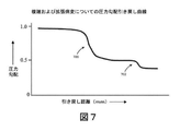
したがって、いくつかの例では、患者の血管系内の複数の位置で複数の測定値(例えば、圧力測定値、圧力勾配など)が取得されることができる。そのような測定値が取得されるそのような相対位置は、例えば、位置センサからの位置情報を使用して判定されることができる。処理エンジン112は、測定情報と関連する位置情報とを効果的に組み合わせるように作用することができる。複数の測定は、ディスプレイ114上など、各測定が行われた相対位置を参照してともに表示されることができる。図7は、患者の血管内の様々な対応する位置に関連する様々な圧力測定値を示す例示的なプロットである。 Thus, in some examples, multiple measurements (eg, pressure measurements, pressure gradients, etc.) can be obtained at multiple locations within the patient's vascular system. Such relative positions from which such measurements are obtained can be determined, for example, using position information from position sensors. The processing engine 112 can act to effectively combine the measurement information with the associated location information. The plurality of measurements can be displayed together with reference to the relative position where each measurement was made, such as on the display 114. FIG. 7 is an exemplary plot showing different pressure measurements associated with different corresponding locations within a patient's blood vessels.
そのようなデータは、血管内の病変または他の圧力に影響を与える特徴の位置を特定するのに有用であり得る。例えば、いくつかの例では、圧力対位置の激しい勾配は、血管内の重度の病変を示している可能性がある。図7の例示では、第1の圧力勾配700は、血管内の重度の病変を示すことができる。第2のより緩やかな勾配702は、血管内のより小さな病変を示すことができる。したがって、図7に示すようなデータは、患者の血管内の病変の位置を突き止めるために使用されることができる。いくつかのそのような実施形態では、病変位置に効果的な治療を提供するために病変の位置を突き止めるために、圧力データに関連付けられた位置情報が使用されることができる。いくつかの例では、図7に示されるような所定距離にわたる圧力データの取得は、複雑な冠状動脈疾患を有するような患者の診断および治療に関する意思決定に有用であり得る。データは、患者内のどの病変が治療されるべきかおよびどの病変が治療される必要がないかを判定するために特に有用であり得る。
Such data can be useful in locating lesions or other pressure-affecting features in blood vessels. For example, in some cases, a steep pressure vs. position gradient may indicate severe lesions within the blood vessel. In the illustration of FIG. 7, the
いくつかの例では、圧力センサの引き戻しは、各位置での1つ以上の心拍の経過にわたって圧力の読取値を取得するために非常にゆっくりと行われる。いくつかの実施形態では、引き戻しを高速化するために、図5Bのセンサ540bおよび542bなどの複数のセンサからの短い間隔の瞬時圧力測定値が記録されることができる。各測定位置ではるかに短い時間間隔を使用して相対圧力勾配を得るために、複数の圧力読取値が読取値の1つに正規化されることができる。
In some examples, the pullback of the pressure sensor is done very slowly to obtain a pressure reading over the course of one or more heartbeats at each position. In some embodiments, short-interval instantaneous pressure measurements from multiple sensors, such as
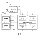
既に説明したように、多くの血管内処置において、システムの様々な態様の位置に関する少なくとも相対位置情報を知ることは有利であり得る。図8は、位置センサを含む血管内システムの実施形態のシステムレベルブロック図である。特に、図8の例示的なシステム800は、カテーテル802と、位置センサ822と、処理エンジン812とを備える。カテーテル802は、センサ808を含むことができ、処理エンジン812と通信することができる。いくつかの実施形態では、処理エンジン812は、センサ808と直接通信する。図8の実施形態では、処理エンジン812は、ディスプレイ814、ユーザインターフェース820、メモリ/データ記憶装置830、およびプロセッサ/コントローラ832を備える。これらの構成要素は、例えば、タッチスクリーンディスプレイおよび/またはコンピュータに統合されてもよい。
As already described, in many intravascular procedures it can be advantageous to know at least relative location information about the location of various aspects of the system. FIG. 8 is a system level block diagram of an embodiment of an intravascular system including a position sensor. In particular, the
いくつかの実施形態では、カテーテル802またはカテーテル802内のセンサ808は、診断または治療機能を実行している間、患者の血管系内で並進されることができる。そのような場合、処理エンジン812は、センサ808から複数の位置で情報を受信することができる。いくつかの実施形態では、処理エンジン812は、複数のセンサ位置から情報を受信し、集約データ組を構築することができる。例えば、IVUSシステムの場合、複数の位置に関連する画像データは、図4のような図を構築するように集約されることができる。MPSシステムの場合、圧力または他のデータは、図7に示されるようなプロットを生成するように集約されることができる。そのような集約データ組は、複数のセンサ808の位置の少なくともサブセットからの情報を含み、ディスプレイ814上での提示のために処理されることができる。そのような情報の集約セットを構築するために、情報が受信された位置間の少なくとも相対的な関係を処理エンジン812が検出することが有用であり得る。したがって、血管内システム800のいくつかの実施形態は、位置センサ822を含む。
In some embodiments, the
図8に示される位置センサ822は、可動要素826および基準要素824を含むことができる。位置センサ822は、例えば、ポテンショメータ、エンコーダ、線形可変差動変換器、または他の適切な位置センサを備えることができる。そのような位置センサ822は、血管内システム800に統合されることができ、処理エンジン812と通信状態に配置されることができる。位置センサ822の可動要素826は、センサ808の位置に相関がある可動要素位置を有することができる。センサ位置と可動要素826の位置との間の相関関係は、図8の破線828によって表されている。位置センサ822の基準要素824は、様々な血管内プロセス(例えば、超音波イメージング、圧力検知など)中にセンサ808の動きに対して実質的に固定されることができる。そのような実施形態では、センサ位置と可動要素位置との間の相関のために、位置センサ822は、位置センサ822の基準要素824に対するセンサ808の相対的な動きを判定するように構成されることができる。いくつかの実施形態では、位置センサ822は、基準要素824に対するセンサ808の相対的な動きを判定することができ、位置センサ822は、処理エンジン812の他の構成要素と通信することができる。
The
図8に示すように、位置センサ822は、処理エンジン812と通信することができる。いくつかの実施形態では、処理エンジン812は、位置センサ822から位置情報を受信するように構成されることができる。位置情報は、基準要素824に対する位置センサ822の可動要素826の位置に関する情報を含むことができる。位置情報は、エンコーダから受信した情報、ポテンショメータからの抵抗情報もしくは他の電気データ、または様々な種類の位置センサからの任意の他の信号もしくは情報を含むことができる。位置センサ822が基準要素824に対するセンサ808の相対的な動きを判定する実施形態では、位置センサ822は、その位置情報を処理エンジン812に提供することができる。いくつかの実施形態では、位置センサ822は、可動要素826および基準要素824に関する情報を処理エンジン812に提供することができ、処理エンジン812は、基準要素824に対するセンサ808の相対的な動きを判定することができる。上述したように、可動要素826の位置は、カテーテル802のセンサ808の位置と相関させることができる。いくつかの実施形態では、位置センサ822は、可動要素826の位置を基準要素824の位置と比較することができ、可動要素826の位置がセンサ808の位置とどのように相関するかを考慮することができ、基準要素824の位置に対するセンサ808の位置を判定することができる。そのような実施形態では、位置センサ822は、センサ808の位置を処理エンジン812に提供することができる。いくつかの実施形態では、位置センサ822は、基準要素824の位置に対する可動要素826の位置に関する情報を処理エンジン812に単に送信することができる。いくつかのそのような実施形態では、処理エンジン812は、可動要素826の位置を基準要素824の位置と比較することができ、可動要素826の位置がセンサ808の位置とどのように相関するかを考慮することができ、基準要素824の位置に対するセンサ808の位置を判定することができる。他の実施形態では、処理エンジン812は、基準要素824に対する可動要素826の動きを測定し、そこからセンサの動きを判定することができる。
As shown in FIG. 8, the
いくつかの実施形態では、処理エンジン812は、血管内カテーテル802からのセンサ情報(例えば、IVUSトランスデューサからの画像情報、MPSなどの圧力センサからの圧力情報など)および位置センサ822からの位置情報を双方とも受信するように構成されることができる。処理エンジン812は、特定の画像情報をセンサ808の相対位置に関連付けることができる。処理エンジン812は、センサ情報および位置情報に基づいて表示を生成するように構成されることができる。
In some embodiments, the
処理エンジン812は、分析されている血管内の複数の長手方向位置に対応するセンサ情報および位置情報を受信および処理することができる。いくつかの構成では、処理エンジン812は、それぞれ第1の可動要素位置に対応する第1の組のセンサ情報および第1の組の位置情報を受信することができる。処理エンジンは、さらに、それぞれが第2の可動要素の位置に対応する第2の組のセンサ情報および第2の組の位置情報を受信することができる。一般に、センサ情報および位置情報は、任意数の可動要素位置に対応する情報を含むことができる。いくつかの好ましい実施形態では、処理エンジン812は、分析される血管に関するリアルタイムデータを表示するためにセンサの並進中にいくつかの位置についてのセンサ情報および位置情報をリアルタイムで処理することができる。
The
本明細書の他の箇所で説明するように、いくつかの実施形態では、可動要素の位置は、センサ808の位置と相関する。したがって、第1および第2の可動要素位置に対応する第1および第2の組のセンサおよび位置情報もまた、第1および第2のセンサ808の位置に対応することができる。可動要素826は、対応した基準要素824に対して移動することができるとともに、センサ808は、様々な位置に患者の血管系内で並進されることができる。センサ808は、いくつかの方法で患者の血管構造を通って並進させることができる。いくつかの実施形態では、カテーテル802は、患者の血管構造を通って並進する。センサ808は、例えば、カテーテル802内、シース内で並進することができる。いくつかの実施形態では、血管内イメージングシステムは、カテーテル802および/またはカテーテル802内のセンサ808を並進させるように構成された並進機構を含むことができる。
In some embodiments, the position of the moving element correlates with the position of the
様々な実施形態において、位置センサ822の要素は、システムの様々な部分に配置されてもよい。例えば、いくつかの例では、可動要素826および基準要素824の一方または双方が並進機構に含まれてもよい。追加的にまたは代替的に、そのような要素の一方または双方は、カテーテル802上に配置されるかあるいはカテーテル内に一体化されることができる。いくつかの例では、システム800は、位置センサ822の少なくとも一部を収容するかまたは支持する専用の位置センサアセンブリ825を含むことができる。
In various embodiments, the elements of the
いくつかの実施形態では、IVUSカテーテルの駆動ケーブル(例えば、268)またはMPSカテーテルの基端部(例えば、550、550b)などのカテーテルの少なくとも一部は、磁化可能な材料から製造される。いくつかの実施形態では、そのようなカテーテルの部分は、交互に磁化され且つ消磁される。他の実施形態では、カテーテルの磁化可能な部分は、様々な磁化を有する磁区を含むことができる。例えば、交番磁界は、既知の間隔(例えば、1ミリメートル毎)でカテーテルの磁化可能な部分に誘導されてもよい。様々な実施形態において、磁化は、カテーテルに対して軸方向または半径方向であり得る。そして、カテーテルの磁化可能な部分は、装置の磁化可能な部分に関連する磁場変動(例えば、パルス)をカウントする磁気ピックアップを通過させるか、さもなければその近くを通過させることができる。いくつかの例では、図8に示すように、可動要素(例えば、826)は、(例えば、磁区を含む)カテーテルの磁化可能な部分を含むことができる。同様に、位置センサ(例えば、822)の基準要素(例えば、824)は、カテーテルの磁区を検出するように構成されたピックアップを含むことができる。 In some embodiments, at least a portion of the catheter, such as the drive cable for an IVUS catheter (eg, 268) or the proximal end of an MPS catheter (eg, 550, 550b), is made from a magnetizable material. In some embodiments, parts of such a catheter are alternately magnetized and degaussed. In other embodiments, the magnetizable portion of the catheter can include magnetic domains with various magnetizations. For example, the alternating magnetic field may be directed to the magnetizable portion of the catheter at known intervals (eg, every millimeter). In various embodiments, the magnetization can be axial or radial with respect to the catheter. The magnetizable portion of the catheter can then pass or otherwise pass a magnetic pickup that counts magnetic field fluctuations (eg, pulses) associated with the magnetizable portion of the device. In some examples, as shown in FIG. 8, the moving element (eg, 826) can include a magnetizable portion of the catheter (eg, including a magnetic domain). Similarly, the reference element (eg, 824) of the position sensor (eg, 822) can include a pickup configured to detect the magnetic domain of the catheter.
いくつかのそのような実施形態では、各磁場変動が既知の距離(例えば、1mm)に相関するため、磁気ピックアップ装置によってカウントされたパルスは、カテーテルによって行われる他の処理(例えば、IVUSイメージングまたはMPS圧力検知センサ108)にその後に関連付けられる距離スケールを提供することができる。磁気ピックアップ装置は、制御要素または回路と通信することができる。そのような制御要素または回路は、血管内処理エンジン(例えば、112)に関連付けられてもよい。したがって、センサ(例えば、108)および磁気ピックアップ装置は、ともにセンサ情報および位置情報を血管内処理エンジンに提供することができる。前述したように、血管内処理エンジンは、例えば、ディスプレイ(例えば、図4のような長手方向IVUS画像または図7のようなMPS圧力曲線)を生成するために、センサ情報および位置情報を組み合わせることができる。 In some such embodiments, each magnetic field variation correlates with a known distance (eg, 1 mm), so the pulse counted by the magnetic pickup device is subjected to other processing performed by the catheter (eg, IVUS imaging or, eg, IVUS imaging). A distance scale associated with the MPS pressure sensing sensor 108) can be provided thereafter. The magnetic pickup device can communicate with a control element or circuit. Such control elements or circuits may be associated with an endovascular processing engine (eg, 112). Therefore, both the sensor (eg, 108) and the magnetic pickup device can provide sensor information and position information to the intravascular processing engine. As mentioned above, the endovascular processing engine combines sensor information and position information, for example, to generate a display (eg, a longitudinal IVUS image as shown in FIG. 4 or an MPS pressure curve as shown in FIG. 7). Can be done.
図9A−図9Cは、カテーテルの磁化可能な部分の例示的な磁区を示している。図9Aは、軸方向に磁化された領域を有するカテーテル902aの磁化可能な部分を示している。示されるように、様々な磁区は、カテーテル902aの磁化可能な部分から外側を指している矢印によって示される磁化方向を有する。図示された実施形態では、磁区は、1mmの長さであるが、多くの磁区サイズが使用されることができる。磁化方向による磁区の順序は、カテーテルの移動距離だけでなく、方向も検出できるように定義されることができる。カテーテル902aの磁化可能な部分と同様に、図9Bのカテーテル902bの磁化可能な部分は、複数の磁区を含む。同様に、磁区の磁化方向が矢印によって示されている。図9Aのカテーテル902aの磁化可能な部分とは対照的に、カテーテル903aの磁化可能な部分の磁化方向は、軸方向に整列している。上述したように、磁化方向による磁区の順序は、カテーテルの移動距離だけでなく方向も検出するように定義されてもよい。
9A-9C show exemplary magnetic domains of the magnetizable portion of the catheter. FIG. 9A shows a magnetizable portion of the
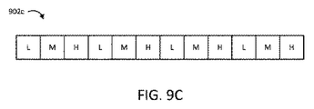
カテーテルの磁化可能な部分(例えば、902a、902b)の変化する磁化方向に加えてまたはその代わりに、いくつかの例では、様々な領域の磁化の大きさが異なっていてもよい。図9Cは、異なる磁化の大きさの磁区を有するカテーテル902cの磁化可能な部分を示している。図示された実施形態では、値が低(L)、中(M)、または高(H)の磁区の大きさを有するように磁区が構成されている。カテーテル902cの磁化可能な部分の動きは、固定位置での磁場強度の検出された変化に基づいて検出されることができる。いくつかの例では、磁場強度の変化を検出することは、カテーテル902cの磁化可能な部分の動きの方向を示すことができる。例えば、図示された実施形態に関して、LからHへの検出された遷移は、第1の方向の動きを示し、LからMへの検出された遷移は、第1の方向とは反対の第2の方向の動きを示す。様々な例では、カテーテル902cの磁化可能な部分の磁区は、半径方向または軸方向に向けられた磁化方向を有することができる。いくつかの実施形態では、各磁区の磁化は、互いに平行であってもよい。他の例では、磁化方向は、任意の他の順序で交互にまたは配列されてもよい。いくつかの実施形態では、検出された磁化方向は、カテーテル902cの磁化可能な部分の動き量および方向の一方または双方を判定するために、検出された磁化の大きさとともに使用されてもよい。
In addition to or instead of the changing direction of magnetization of the magnetizable portion of the catheter (eg, 902a, 902b), in some examples the magnitude of magnetization in the various regions may vary. FIG. 9C shows a magnetizable portion of the
記載したように、カテーテルの様々な部分は、磁気的に検出可能な領域を含むことができる。いくつかの実施形態では、カテーテルのそのような部分の動きは、典型的なシステム動作中に検出可能な磁区の位置に近接した1つ以上のピックアップによって検出されることができる。例えば、いくつかの実施形態では、磁区は、患者内の血管内センサと同時に動くように構成されたケーブルなどのカテーテルの1つ以上のシステム磁化可能部分に一体化されてもよい。そのようなケーブルは、カテーテルのセンサ(例えば、図1の108)と同時に動くシステムの1つ以上の要素を指してもよい。いくつかの例では、センサは、そのようなケーブルに結合されたIVUSトランスデューサまたは圧力センサ(例えば、MPS)を含むことができる。例えば、いくつかのそのようなシステムでは、ケーブルは、IVUSシステムカテーテルの駆動ケーブル(例えば、図2の268)またはMPSシステムにおけるハイポチューブなどのセンサ送達装置(例えば、図5Aの510)の基端部(例えば、550)を含むことができる。カテーテルまたはシステムの他の可動部分は、追加的または代替的に、そのような検出可能な磁区を含むことができる。様々な実施形態において、磁区およびシステム動作中に移動するように構成されたカテーテル(902a〜c)の磁化可能な部分の一方または両方は、位置センサ(例えば、826)の可動要素(例えば826)であると考えることができる。 As described, various parts of the catheter can include magnetically detectable areas. In some embodiments, the movement of such a portion of the catheter can be detected by one or more pickups in close proximity to the location of the magnetic domain that can be detected during typical system operation. For example, in some embodiments, the magnetic domain may be integrated into one or more system magnetizable parts of the catheter, such as a cable configured to move simultaneously with an intravascular sensor in the patient. Such a cable may refer to one or more elements of the system that operate simultaneously with the catheter's sensor (eg, 108 in FIG. 1). In some examples, the sensor can include an IVUS transducer or pressure sensor (eg, MPS) coupled to such a cable. For example, in some such systems, the cable is the proximal end of a drive cable for an IVUS system catheter (eg, 268 in FIG. 2) or a sensor delivery device (eg, 510 in FIG. 5A) such as a hypotube in an MPS system. Parts (eg, 550) can be included. The catheter or other moving part of the system may additionally or optionally include such detectable magnetic domains. In various embodiments, one or both of the magnetizable portions of the magnetic domain and catheters (902a-c) configured to move during system operation are movable elements (eg 826) of the position sensor (eg 826). Can be thought of as.
いくつかの実施形態では、磁区の磁化は、カテーテルの磁化可能な部分の材料特性であってもよい。すなわち、カテーテルの部分は、磁区が「書き込まれた」または形成された磁性材料(冷間加工されたステンレス鋼など)から構成されてもよい。いくつかの他の例では、カテーテルの磁化可能な部分は、非磁性材料から構成されることができるが、塗布された磁気コーティングを含んでもよい。磁気コーティングは、同様に、そこに「書き込まれた」磁区を含むことができる。 In some embodiments, the magnetization of the magnetic domain may be a material property of the magnetizable portion of the catheter. That is, the portion of the catheter may be composed of a magnetic material (such as cold-worked stainless steel) in which magnetic domains are "written" or formed. In some other examples, the magnetizable portion of the catheter can be composed of a non-magnetic material, but may include an applied magnetic coating. The magnetic coating can likewise include a "written" magnetic domain therein.
図10は、血管内システムで使用するための例示的な磁気ピックアップの概略図である。図10のピックアップ1050は、直列に配置され且つ回路を形成する複数の磁気抵抗装置1060a−1060dを含む。装置1060a−1060dのネットワークの反対側にバイアス電圧(V_bias)が印加され、印加された磁場(破線で示される)がネットワークにわたって印加される。いくつかの例では、磁気抵抗装置1060a−1060dは、装置1060a−1060dの抵抗が経験された磁場の強度および方向に依存する異方性磁気抵抗(AMR)を経験する。図示された実施形態では、磁気抵抗装置1060a−1060dのネットワークによって、(例えば、図9A−図9Cに示されているような;実線で示されるような)カテーテルの磁区などからの磁場が経験される。印加された磁場と経験された磁場の組み合わせは、磁気抵抗装置1060a−1060dの抵抗に最終的に影響を及ぼす。抵抗の変化は、順次、各装置にわたって降下したバイアス電圧の量に影響を与える。
FIG. 10 is a schematic representation of an exemplary magnetic pickup for use in an intravascular system. The
図示された実施形態では、磁気抵抗装置1060aと1060cとの接合部と磁気抵抗装置1060bと1060dとの接合部との間の電圧(V_measure)が測定される。したがって、測定された電圧(V_measure)は、磁気抵抗装置1060aおよび磁気抵抗装置1060bによって降下された電圧の差を示す。当業者によって理解されるように、正味の磁場は、装置1060a−dおよび1060bのそれぞれの抵抗に異なる影響を与えることがある。その結果、磁場の存在および欠如(または磁場の方向の切り替え)は、装置1060a−dの相対抵抗の変化および測定された電圧の変化(V_measure)をもたらす。
In the illustrated embodiment, the voltage (V_measure) between the junction between the
したがって、測定された電圧(V_measure)は、ピックアップ1050における磁場の変化を検出するために監視されてもよい。したがって、ピックアップ1050を通過するカテーテルの磁化可能な部分の動きを示すために測定電圧の変化が使用されることができる。図示された実施形態では、ピックアップ1050は、血管内処理エンジン1012と通信しているものとして示されている。血管内処理エンジン1012は、測定された電圧(V_measure)を示す信号を受信するように構成されてもよい。いくつかの例では、血管内処理エンジン1012は、電圧を直接測定することができる。追加的にまたは代替的に、血管内処理エンジン1012は、バイアス電圧(V_bias)をピックアップ1050に印加するように構成されることができる。
Therefore, the measured voltage (V_measure) may be monitored to detect changes in the magnetic field at
いくつかの代替実施形態では、バイアス電圧を供給することおよび測定された電圧を測定することの一方または双方は、1つ以上の別個の構成要素によって行うことができる。例えば、いくつかの実施形態では、バイアス電圧は、別個の電源、電池などのスタンドアローン装置によって提供されてもよい。追加的にまたは代替的に、測定された電圧は、血管内処理エンジン1012とは別個の追加の回路に印加されてもよい。そのような追加の回路は、測定された電圧の変化を検出し、そのような変化を表す信号を血管内処理エンジン1012に出力するように構成されることができる。例えば、いくつかの実施形態では、測定された電圧を受信するように構成された追加の回路は、測定された電圧を血管内処理エンジン1012に伝達することができる。他の例では、追加の回路は、測定された電圧の変化がいつ発生するか(例えば、閾値の上または下の交差、符号の変化など)を判定することができる。追加の回路は、変化を示す信号を血管内処理エンジン1012に伝達することができるが、測定された電圧の値を含む必要はない。
In some alternative embodiments, one or both of supplying the bias voltage and measuring the measured voltage can be performed by one or more separate components. For example, in some embodiments, the bias voltage may be provided by a separate power supply, stand-alone device such as a battery. Additional or alternative, the measured voltage may be applied to an additional circuit separate from the
一般に、様々な実施形態において、追加の回路は、ピックアップ1050に近接するカテーテルの磁化可能な部分の磁気特性を表す信号を血管内処理エンジン1012に伝達することができる。血管内処理エンジン1012は、そのような情報を受信し、患者内のカテーテルの要素の相対位置または動きのその後の判定を行うことができる。回路と血管内処理エンジン1012との間の通信は、例えばブルートゥースまたはWi−Fi接続を介した有線または無線とすることができる。ピックアップ1050と血管内処理エンジン1012との間の接続は、いくつかの実施形態にかかる例示的な接続を示すことが理解されよう。説明したように、バイアス電圧は、血管内処理エンジン1012の動作によって印加されるか、制御されるか、またはそれから完全に独立することができる。同様に、測定された電圧は、血管内処理エンジン1012に直接印加されてもよく、有線または無線のいずれかの追加の回路によってそれに伝達されてもよい。追加的にまたは代替的に、追加の回路は、測定された電圧の値を実際に直接伝達することなく、測定された電圧に基づいて信号を提供することができる。
In general, in various embodiments, the additional circuit can transmit a signal to the
前述したように、磁区は、半径方向または軸方向に配向された磁化を有するケーブル(または他のシステム構成要素)に書き込むことができる。図10の1050のような1つ以上のピックアップは、半径方向または軸方向のいずれかである検出された磁区(およびカテーテルの動きによるその中の変化)に基づいて出力を生成するように構成されてもよい。いくつかの実施形態では、典型的なシステム動作中に検出可能な磁区の位置に近接した1つ以上のピックアップによってそのようなカテーテルの部分の動きが検出されることができる。したがって、いくつかの例では、図10の1050などのピックアップは、血管内システム内の位置センサ(例えば、822)の基準要素(例えば、824)として使用されることができる。 As mentioned above, magnetic domains can be written to cables (or other system components) that have magnetization that is radially or axially oriented. One or more pickups, such as 1050 in FIG. 10, are configured to generate output based on detected magnetic domains (and changes in them due to catheter movement) that are either radial or axial. You may. In some embodiments, movement of such catheter portions can be detected by one or more pickups in close proximity to detectable magnetic domains during typical system operation. Thus, in some examples, a pickup such as 1050 in FIG. 10 can be used as a reference element (eg, 824) for a position sensor (eg, 822) within the intravascular system.
図11−図13は、本発明の様々な実施形態にかかる様々なピックアップ位置を示す例示的な図である。図11は、カテーテルを受け入れる弁に配置されたピックアップを示す概略図である。示されるように、カテーテル1102は、患者1118に配置された弁1109を通って延びる。弁1109は、例えば、上述した止血弁を含むことができる。図示された実施形態では、実線で示されたカテーテル1102の部分は、患者1118および弁1109の外側にあり、破線の部分は、弁1109内に少なくとも部分的に延びている。
11-13 are exemplary diagrams showing different pickup positions according to different embodiments of the present invention. FIG. 11 is a schematic showing a pickup located on a valve that receives a catheter. As shown,
カテーテル1102は、典型的な血管内手術中に、弁1109に近接してカテーテル1102に沿って配置された磁区1170を含む。様々な実施形態において、磁区1170は、IVUSシステムの駆動ケーブルまたはMPSシステムのセンサ送達装置の基端部など、カテーテル1102の可動部分の一部であってもよい。本明細書の他の箇所に記載されているように、磁区1170は、様々な方向に配向された磁化および/または様々な大きさを有する磁化を有することができる。磁区1170におけるそのような差は、カテーテル1102の一部の動きを検出するために近接領域1170の間の区別を可能にする。
弁1109は、ピックアップ1150がカテーテル1102の磁区1170を検出できるように、カテーテル1102に近接して配置されたピックアップ1150を含む。ピックアップ1150は、図10に示すような磁気抵抗センサであってもよく、またはホール効果センサなどの磁区1170を検出することができる他のピックアップであってもよい。ピックアップ1150は、ピックアップに存在する磁場に基づいて信号を出力するように構成されることができる。ピックアップ1150における磁場は、ピックアップ1150に近接する磁区1170の磁化を示すことができる。したがって、信号の変化は、ピックアップ1150に近接する磁区1170の変化、したがってカテーテル1102の一部の位置の変化を表すことができる。
The
図示された実施形態では、弁1109は、ピックアップ1150と連通する通信ユニット1152を含む。通信ユニット1152は、ピックアップ1150から信号を受信するように構成されることができる。例えば、通信ユニット1152は、図10に示すようなピックアップから測定電圧(V_measure)を受信するように構成されてもよい。通信ユニット1152は、システム内の他の場所で信号または代表信号を通信するようにさらに構成されてもよい。通信ユニット1152は、有線または無線伝送の一方または双方によって信号を通信することができる。いくつかの実施形態では、通信ユニット1152は、信号を他のシステム構成要素に通信するための1本以上のワイヤを受け入れる出力ポートを含むことができる。追加的にまたは代替的に、通信ユニット1152は、任意の適切な無線通信構成要素を含んでもよい。
In the illustrated embodiment, the
いくつかの実施形態では、通信ユニット1152は、血管内処理エンジン(例えば、112)と有線または無線で通信する。血管内処理エンジンは、ピックアップ1150からの信号を表す信号を通信ユニット1152から受信することができる。いくつかのそのような実施形態では、血管内処理エンジンは、通信ユニット1152から受信した信号を、カテーテル1102の磁化可能な部分の1つ以上の位置または位置の変化と関連付けることができる。すなわち、磁区(例えば、1170)を有するカテーテル1102の一部(例えば、IVUSカテーテルの駆動ケーブルまたはMPSカテーテルの基端部)が弁1109を通ってピックアップ1150を通過して移動すると、ピックアップ1150から出力される信号は、通信ユニット1152を介して血管内処理エンジンに伝達されることができる。
In some embodiments, the communication unit 1152 communicates with an intravascular processing engine (eg, 112) by wire or wirelessly. The intravascular processing engine can receive a signal representing the signal from the
いくつかの実施形態では、弁1109は、ピックアップ1150および通信ユニット1152のうちの1つ以上に電力を供給するための電池1154などの電源を含むことができる。例示的な実施形態では、電池1154は、図10に示すようなピックアップのバイアス電圧(V_bias)を提供するように構成される。図11には電池1154として示されているが、弁1109の構成要素に電力を供給するために、容量性エネルギー貯蔵装置または外部電源から弁1109に供給される電力などの任意の様々な電源が使用されることができる。
In some embodiments, the
前述のように、いくつかの例では、システムは、位置センサを収容するように構成された専用の位置検知アセンブリを含むことができる。図12は、例示的な位置検知アセンブリの断面図である。図示された実施形態では、位置検知アセンブリ1280は、カテーテル1202のアンカー1203を受け入れるための溝1243を含む。アンカー1203と溝1243との係合は、カテーテルの一部をシステムの他の構成要素に対して静止状態に保つように作用することができる。例えば、いくつかの実施形態では、アンカー1203は、溝1243と係合し、IVUSカテーテルのシースを適所に保持する一方で、駆動ケーブルは、トランスデューサをそれに対して移動させる。同様に、アンカー1203および溝1243は、センサ送達装置およびセンサがそれに対して移動される間、MPSシステムのガイドワイヤを適所に保持するように作用することができる。
As mentioned above, in some examples, the system can include a dedicated position sensing assembly configured to accommodate the position sensor. FIG. 12 is a cross-sectional view of an exemplary position sensing assembly. In the illustrated embodiment, the
図示された実施形態では、カテーテル1202は、さらに、例えば血管内処理エンジンの取り付け点1256とインターフェース接続するために、基端方向に位置検知アセンブリ1280を通ってコネクタ1285まで延びるケーブル1268を含む。いくつかの実施形態では、ケーブル1268は、アンカー1203に対して移動するように構成された様々なカテーテル1202構成要素のうちの任意のものを含むことができる。例えば、ケーブル1268は、IVUSカテーテルの駆動ケーブルまたはMPSシステムのセンサ送達装置の基端部を含むことができる。
In the illustrated embodiment, the
図12の実施形態では、ケーブル1286は、本明細書の別の場所に記載されているような磁区1270を含む。磁区1270は、図9A−Cに示すような様々な磁化の大きさおよび方向を有することができる。血管内手術の間、センサ(例えば、IVUSトランスデューサまたはMPS圧力センサ)は、患者の血管構造を通って移動されると、ケーブル1268は、位置検知アセンブリ1280を通って移動することができる。
In the embodiment of FIG. 12, the cable 1286 includes a
例えば、コネクタ1285は、血管内処理エンジンとカテーテル1202との間に電気機械的インターフェースを提供する患者インターフェースモジュール(PIM)と係合することができる。いくつかの例では、PIMは、図1のシステムにおける血管内処理エンジン(例えば、112)および/またはインターフェース要素(例えば、110)の一部であってもよい。PIMは、(例えば、並進機構、手動操作などを介して)並進することができ、それにより、カテーテル1202の一部(例えば、ケーブル1268および関連する血管内センサ)を患者の血管系内で並進させる。そのような実施形態では、PIMの並進は、位置検知アセンブリ1280を通る磁区1270の移動をもたらすことができる。
For example,
位置検知アセンブリ1280は、カテーテル1202の磁区1170を検出するように構成されたピックアップ1250をさらに含むことができる。いくつかの実施形態では、ピックアップ1250は、図10のピックアップ1050と同様であってもよい。他の実施形態では、ピックアップ1250は、ホール効果センサなどの磁区1270からの磁場を検出することができる任意の適切なセンサとすることができる。いくつかの実施形態では、位置検知アセンブリ1280は、ピックアップ1250が望ましくない磁場を検知するのを防止するために、ピックアップ1250に近接して配置された遮蔽要素1255を含む。遮蔽部1255は、導電性材料などの任意の適切な遮蔽材料を含むことができる。いくつかの実施形態では、遮蔽部1255は、ピックアップ1250に対して基準電位または接地電位に電気的に結合されてもよい。
The
図11の弁1109と同様に、位置検知アセンブリ1280は、ピックアップ1250から信号を受信するための通信ユニット1252を含むことができる。通信ユニット1252は、有線または無線通信を介してセンサから受信された信号を表す他のシステム構成要素(例えば、血管内処理エンジン)に信号を通信するように構成されてもよい。位置検知アセンブリ1280は、ピックアップ1250および通信ユニット1252の一方または双方に電力を供給するための電池1254および/または他の適切な電源を含むことができる。
Similar to
いくつかの実施形態では、カテーテル102は、トランスデューサ108の動きを容易にするために互いに対して伸縮するように構成された第1および第2の伸縮部を備えることができる。伸縮部は、例えば、カテーテルの固定部分(例えば、図12のアンカー1203)に対するカテーテルおよび血管内センサの一部の移動を容易にするためのインターフェース要素(例えば、図1の110)など、カテーテルのアンカー部(例えば、図12の1203)およびシステムの様々な場所に配置された溝(例えば、図12の1243)と組み合わせて使用されることができる。図13Aおよび図13Bは、血管内システムにおいて使用されることができる血管内カテーテル1302の一部としての第1および第2の伸縮部1364、1366の例示的な構成である。図13Aは、血管内カテーテル1302の一部としての第1の伸縮部1364および第2の伸縮部1366を示している。例示された実施形態においてカテーテル1302の一部として示されているが、伸縮部は、いくつかのシステムにおいてカテーテルの外部にあってもよいことが理解されよう。図13Aに示される例では、第1の伸縮部1364は、第2の伸縮部1366内の開口に窪んでいる。第1および第2の伸縮部1364、1366は、それらの間の相対的な移動を可能にするように摺動可能に結合されることができる。
In some embodiments, the
図13Bは、図13Aの血管内カテーテル1302の第1および第2の伸縮部1364、1366を示しており、第1の伸縮部1364は、第2の伸縮部1366から延びている。多くの実施形態では、第1および第2の伸縮部1364、1366は、図13Aおよび図13Bに示される構成の間で自由に並進するように構成されることができる。すなわち、第1および第2の伸縮部1364、1366は、互いに対して「伸縮」することができる。いくつかの実施形態では、第1および第2の伸縮部1364、1366の一方は、並進機構の静止部分などの患者に対して静止したままである血管内システムの構成要素に固定されることができる。
13B shows the first and second
いくつかの実施形態では、血管内センサ1308(例えば、IVUSトランスデューサ、MPS圧力センサなど)は、第1および第2の伸縮部1364、1366の一方に結合されることができ、他方には結合されることができない。そのような構成では、センサ1308に結合されていない伸縮部は、固定されたままである一方で、他方の伸縮部は、それに対して移動することができ、それによって固定伸縮部に対するセンサ1308の動きを生じさせる。したがって、第1および第2の伸縮部1364、1366の伸縮運動は、センサ1308の動きを容易にすることができる。例示的な実施形態では、センサ1308は、第1の伸縮部1364に結合される一方で、第2の伸縮部1366は、システムの固定構成要素に固定される。センサ1308の動きが(例えば、手動並進、電動並進などを介して)作動されると、第1の伸縮部1364は、第2の伸縮部1366内で並進することができる。いくつかの実施形態では、センサ1308は、第2の伸縮部1366に結合されることができる一方で、第1の伸縮部1364は、システムの固定構成要素に固定される。センサ1308の動きが作動されると(手動並進、電動並進など)、第2の伸縮部1366は、第1の伸縮部1364の外側で並進することができる。様々な構成において、センサ1308は、駆動ケーブルまたはセンサ送達装置の基端部を介して、第1の伸縮部1364または第2の伸縮部1366に結合されることができる。あるいは、いくつかのシステムでは、第1の伸縮部1364または第2の伸縮部1366は、駆動ケーブルの一部またはセンサ送達自体の基端部とすることができる。
In some embodiments, the intravascular sensor 1308 (eg, IVUS transducer, MPS pressure sensor, etc.) can be coupled to one of the first and second
いくつかの実施形態では、カテーテル1302の第1および第2の伸縮部1364、1366の相対的な動きは、患者の血管構造内のセンサ1308の動きと相関させることができる。そのようないくつかの例では、第1の伸縮部1364および第2の伸縮部1366の一方は、磁区1370を含むことができる一方で、他方は、磁区の位置および/または動きを検知することができるピックアップを含む。図示された実施形態では、第1の伸縮部1364は、例えば、図9A−C、図11および図12に関して説明されたような複数の磁区1370を含む。上述したように、磁区1370は、ピックアップ1350を過ぎて移動するときに磁区を区別するために使用されることができる様々な磁化方向および/または大きさを含むことができる。上述した実施形態と同様に、磁区1370は、第1の伸縮部1364の材料と一体であってもよく、または第1の伸縮部1364上に配置された磁化可能なコーティング内に形成されてもよい。
In some embodiments, the relative movement of the first and second
したがって、いくつかのそのような実施形態では、第2の伸縮部1366に対する第1の伸縮部1364の移動(例えば、図13A−Bの図示された構成の間)および患者内のセンサ1308の動きは、第2の伸縮部1366に配置されたピックアップ1350に対する磁区1370の動きをもたらす。したがって、ピックアップ1350によって受ける磁場は、センサ1308が患者内を移動するにつれて変化する。他の実施形態に関して説明したように、ピックアップ1350は、経験された磁場を表す信号を出力することができる。磁場がセンサ1308の位置に対して変化するため、ピックアップ1350からの信号出力の変化は、センサ1308の位置の変化を表すことができる。ピックアップ1350から出力された信号は、ピックアップ1350から受信した信号またはそれを表す信号を血管内処理エンジンに通信するように構成された通信ユニット1352によって受信されることができる。したがって、そのようないくつかの例では、血管内処理エンジンは、患者内のセンサ1308の位置および/または位置の変化を表す信号を通信ユニット1352から受信する。図示された実施形態では、第2の伸縮部1366は、ピックアップ1350および通信ユニット1352のうちの1つ以上に電力を供給するための電池1354を含む。電池1354は、そのような電力を供給するための任意の様々な電源を含むことができ、それぞれ図11および図12に関して説明した電池1154および1254と同様とすることができる。
Thus, in some such embodiments, the movement of the
磁区1370は、第1の伸縮部1364およびピックアップ1350、通信ユニット1352、および第2の伸縮部1366の電池1354上に配置されているように示されているが、代替構成も可能であることが理解されよう。例えば、第2の伸縮部1366に磁区が配置されることができる一方で、第1の伸縮部1364にピックアップ1350、通信ユニット1352、および電池1354が配置される。追加的にまたは代替的に、通信ユニット1352および電池1354は、ピックアップ1350の同じ部分に含まれる必要はない。一般に、通信ユニット1352および電池1354のそれぞれは、ピックアップ1350および磁区1370の他の位置およびその位置とは無関係に、第1の伸縮部1364または第2の伸縮部1366に配置されることができる。
Although the
図示された実施形態は、それらの間に空白スペースを有する網掛けされた磁区(例えば、1170、1270、1370)を示しているが、磁区は、非磁化空間によって分離される必要はないことが理解されよう。いくつかの例では、図示された網掛けされた磁区間の空間はまた、例えば、隣接する網掛けされた磁区とは異なる磁化を有する磁区を含んでもよい。追加的にまたは代替的に、隣接する網掛けされた磁区は、互いに区別可能な磁化を有する。さらなる実施形態では、磁区は、非磁性材料によって互いに分離されてもよく、または互いに直接隣接していてもよい。 The illustrated embodiments show shaded magnetic domains (eg, 1170, 1270, 1370) with blank spaces between them, although the magnetic domains do not need to be separated by a non-magnetized space. Will be understood. In some examples, the space of the shaded magnetic domains shown may also include, for example, magnetic domains having different magnetizations than adjacent shaded magnetic domains. Additional or alternative, adjacent shaded magnetic domains have magnetizations that are distinguishable from each other. In a further embodiment, the magnetic domains may be separated from each other by a non-magnetic material or may be directly adjacent to each other.
上述したように、様々な実施形態において、血管内処理エンジンは、ピックアップ(例えば、図10のピックアップまたはホール効果センサなどの他の磁気検知素子)に対する磁区の位置および/または動きを示す信号を通信ユニット(例えば、1152、1252、1352)から受信するように構成される。血管内処理エンジンによって受信された信号は、ピックアップによって生成された信号を含んでもよく、またはピックアップによって生成された信号とは異なるがそれに基づく信号であってもよい。例えば、通信ユニットは、ピックアップにおける磁場が任意数の閾値よりも大きいか否かに基づいて、血管内処理エンジンに信号を出力するように構成されてもよい。 As mentioned above, in various embodiments, the intravascular processing engine communicates a signal indicating the position and / or movement of the magnetic domain with respect to the pickup (eg, the pickup in FIG. 10 or another magnetic sensing element such as the Hall effect sensor). It is configured to receive from a unit (eg, 1152, 1252, 1352). The signal received by the endovascular processing engine may include a signal generated by the pickup, or may be a signal different from but based on the signal generated by the pickup. For example, the communication unit may be configured to output a signal to the endovascular processing engine based on whether the magnetic field in the pickup is greater than an arbitrary number of thresholds.
通信ユニットは、信号を有線または無線送信を介して血管内処理エンジンに送信するように構成されてもよい。血管内処理エンジンは、通信ユニットから信号を受信し、受信信号に基づいて、患者内の血管内センサの位置に関連する位置情報を判定することができる。 The communication unit may be configured to transmit the signal to the intravascular processing engine via wired or wireless transmission. The intravascular processing engine can receive a signal from the communication unit and determine position information related to the position of the intravascular sensor in the patient based on the received signal.
位置情報は、患者の血管構造内のセンサの相対位置または絶対位置を示すことができる。本明細書の他の箇所に記載されているように、磁区の磁化の大きさおよび方向を変化させることは、磁区が互いに区別可能となることをもたらす。したがって、ピックアップに存在する磁場の変化は、ピックアップに近接する磁区の変化を示し、したがって、いくつかの実施形態では、患者内のセンサの動きを示す。ピックアップにおける磁場の検出された変化(すなわち、磁区の位置の変化)と磁区のサイズおよび間隔に関する情報を組み合わせることは、磁区の移動量を判定するために使用されることができる。 Positional information can indicate the relative or absolute position of the sensor within the patient's vascular structure. Changing the magnitude and direction of the magnetization of the magnetic domains, as described elsewhere herein, results in the magnetic domains being distinguishable from each other. Therefore, changes in the magnetic field present in the pickup indicate changes in the magnetic domain in close proximity to the pickup, and thus, in some embodiments, movement of the sensor within the patient. Combining the detected changes in the magnetic field at the pickup (ie, changes in the position of the magnetic domains) with information about the size and spacing of the magnetic domains can be used to determine the amount of movement of the magnetic domains.
上述したように、いくつかの実施形態では、磁区の動きの方向(したがって、カテーテルの一部)が判定されることができるように磁区が配置されることができる。例えば、低、中、および高の順序で繰り返し配置された磁区の磁化の大きさが使用されることができる。そのような例では、中磁場磁区が続く低磁場磁区は、第1の方向の動きを示す一方で、高磁場磁区が続く低磁場磁区は、第1の方向と反対の動きを示す。追加的にまたは代替的に、磁区が一方向または他方向に移動しているかどうかを検出するために、複数のピックアップ要素が使用されることができる。 As mentioned above, in some embodiments, the magnetic domains can be arranged so that the direction of movement of the magnetic domains (and thus part of the catheter) can be determined. For example, the magnitude of magnetization of magnetic domains that are repeatedly placed in the order of low, medium, and high can be used. In such an example, a low magnetic domain followed by a medium magnetic domain exhibits movement in the first direction, while a low magnetic domain followed by a high magnetic domain exhibits movement in the opposite direction to the first direction. Additional or alternative, multiple pickup elements can be used to detect whether the magnetic domain is moving in one or the other direction.
いくつかの例では、血管内処理エンジンは、対応するセンサ情報に位置情報を関連付けることができる。組み合わされた位置およびセンサ情報は、図4の長手方向IVUS画像または図7のMPS圧力−距離曲線などの長手方向データを生成するために使用されてもよい。そのような情報は、血管内の病変または他の特徴の位置を判定することを含む、患者の状態をより良好に診断するのに有用であり得る。追加的にまたは代替的に、関連付けられた位置およびセンサ情報は、改善され且つ局所的な治療を可能にすることができる。例えば、関連する位置およびセンサ情報は、臨床医が血管内の重度の病変(例えば、図7の位置700)を突き止めること、および病変を治療するための最適位置にステントを正確に位置決めすることを可能にすることができる。
In some examples, the endovascular processing engine can associate location information with the corresponding sensor information. The combined position and sensor information may be used to generate longitudinal data such as the longitudinal IVUS image of FIG. 4 or the MPS pressure-distance curve of FIG. Such information can be useful in better diagnosing a patient's condition, including determining the location of lesions or other features within a blood vessel. Additional or alternative, the associated position and sensor information can be improved and allow for topical treatment. For example, relevant location and sensor information may indicate that the clinician can locate a severe lesion in a blood vessel (eg,
様々な構成が記載されている。カテーテル上またはカテーテルに近接して配置された磁区に関連する位置センサから取得された位置情報は、対応するセンサ情報と関連付けるために血管内処理エンジンによって取得されてもよい。様々な実施形態では、そのような位置情報は、IVUSトランスデューサから取得された画像データまたは圧力センサ(例えば、MPS)から取得された圧力データに関連付けられることができる。IVUS長手方向画像(例えば、図4の426)または圧力・位置プロット(例えば、図7のプロット)などのデータの組を生成するために、得られた関連データの組(例えば、位置および画像データ、位置および圧力データなど)が使用されることができる。そのような情報は、患者の状態をより正確に分析するためにシステムオペレータによって使用されることができる。これは、より詳細な診断およびより正確に定義された治療計画を可能にする。いくつかの場合において、データは、患者内で最も有効な治療位置を判定するために使用され、いくつかのさらなる例では、判定された位置で治療を実行するために使用されることができる。 Various configurations are described. Positional information obtained from position sensors associated with magnetic domains located on or in close proximity to the catheter may be obtained by an endovascular processing engine to correlate with the corresponding sensor information. In various embodiments, such location information can be associated with image data obtained from an IVUS transducer or pressure data obtained from a pressure sensor (eg, MPS). A set of relevant data (eg, position and image data) obtained to generate a set of data such as an IVUS longitudinal image (eg, 426 of FIG. 4) or a pressure / position plot (eg, plot of FIG. 7). , Position and pressure data, etc.) can be used. Such information can be used by system operators to more accurately analyze the patient's condition. This allows for more detailed diagnosis and more precisely defined treatment planning. In some cases, the data can be used to determine the most effective treatment location within the patient, and in some further examples, to perform treatment at the determined location.
本発明の様々な態様は、非一時的コンピュータ可読媒体において具体化されることができる。非一時的コンピュータ可読媒体は、血管内カテーテル(例えば、102)の先端(例えば、106)の近くに位置するセンサ(例えば、108)からセンサ情報、および(例えば、1つ以上の磁区を含む)位置センサからの位置情報をプロセッサに受信させるための実行可能命令を含むことができる。位置センサは、可動要素および基準要素を備えることができ、位置情報は、基準要素に対する、およびセンサ位置と相関する可動要素の位置を表す可動要素位置を含むことができる。非一時的コンピュータ可読媒体は、さらに、プロセッサに、センサ情報が取得された位置に対応する位置情報とセンサ情報とを関連付けさせる実行可能命令を含むことができる。いくつかの実施形態では、非一時的コンピュータ可読媒体は、受信したセンサ情報および位置情報に基づいてディスプレイを生成することができる。例えば、IVUSカテーテルからの位置情報と対応する画像情報とを含む長手方向画像が生成されることができる。他の例では、圧力センサ(例えば、MPS)からの位置情報および対応する圧力情報を含む圧力対距離曲線が生成されることができる。いくつかの実施形態では、非一時的コンピュータ可読媒体は、処理エンジン112内で具体化されることができる。いくつかの実施形態では、非一時的コンピュータ可読媒体は、本明細書に記載された任意の方法をプロセッサに実行させるための実行可能命令を含むことができる。 Various aspects of the invention can be embodied in non-transitory computer-readable media. Non-transient computer-readable media include sensor information from a sensor (eg, 108) located near the tip (eg, 106) of an intravascular catheter (eg, 102), and (eg, one or more magnetic sections). It can include an executable instruction to cause the processor to receive position information from the position sensor. The position sensor can include a movable element and a reference element, and the position information can include a movable element position that represents the position of the movable element with respect to the reference element and that correlates with the sensor position. The non-transitory computer-readable medium can further include an executable instruction that causes the processor to associate the sensor information with the position information corresponding to the position from which the sensor information was acquired. In some embodiments, the non-transitory computer-readable medium can generate a display based on received sensor information and location information. For example, a longitudinal image can be generated that includes position information from an IVUS catheter and corresponding image information. In another example, a pressure vs. distance curve can be generated that includes position information from a pressure sensor (eg, MPS) and corresponding pressure information. In some embodiments, the non-transitory computer-readable medium can be embodied within the processing engine 112. In some embodiments, the non-transitory computer-readable medium can include executable instructions for causing the processor to perform any of the methods described herein.
本発明の特定の実施形態に関して説明された構成要素は、さらなる実施形態を形成するために組み合わせられることができることが理解されるべきである。コンピュータ可読記憶媒体に埋め込まれまたは符号化された命令は、プログラム可能なプロセッサまたは他のプロセッサに、規定された命令に従わせることができる。コンピュータ可読記憶媒体は、ランダムアクセスメモリ(RAM)、読み取り専用メモリ(ROM)、ハードディスク、光媒体、または他のコンピュータ可読媒体を含むことができる。 It should be understood that the components described for a particular embodiment of the invention can be combined to form further embodiments. Instructions embedded or encoded in a computer-readable storage medium can cause a programmable processor or other processor to obey the specified instructions. Computer-readable storage media can include random access memory (RAM), read-only memory (ROM), hard disks, optical media, or other computer-readable media.
様々な実施形態が記載された。そのような実施形態は、例示的なものであり、決して本発明の範囲を限定するものではない。むしろ、これらのおよび他の実施形態は、以下の特許請求の範囲内にある。 Various embodiments have been described. Such embodiments are exemplary and by no means limit the scope of the invention. Rather, these and other embodiments are within the scope of the following claims.
Claims (18)
基端と、先端と、複数の磁区と、前記先端に配置されたセンサと、カテーテルの前記基端からカテーテルの前記先端まで延び且つ前記先端で前記センサに動作可能に接続されたケーブルと、を含むカテーテルであって、前記センサが患者の1つ以上の血管内特性を表すセンサ情報を提供するように構成されており、前記複数の磁区は、磁区の各グループが、連続的に配置された、第1の磁区の大きさを有する1つの磁区と、前記第1の磁区の大きさよりも大きな第2の磁区の大きさを有する1つの磁区と、前記第1の磁区の大きさ及び前記第2の磁区の大きさの各々よりも大きな第3の磁区の大きさを有する1つの磁区とを有するように、磁区の複数のグループで連続的に配置されており、前記磁区の各グループにおける前記第1の磁区の大きさは、同じ第1の磁区の大きさであり、前記磁区の各グループにおける前記第2の磁区の大きさは、同じ第2の磁区の大きさであり、前記磁区の各グループにおける前記第3の磁区の大きさは、同じ第3の磁区の大きさである、カテーテルと、
前記複数の磁区によって生成された磁気ピックアップの磁場に基づいてピックアップ信号を出力するように構成された磁気ピックアップと、
前記カテーテルのセンサおよび前記磁気ピックアップと通信する血管内処理エンジンであって、
(i)前記カテーテルの前記センサから前記センサ情報を受信し、
(ii)前記ピックアップ信号を表す位置信号を受信し、
(iii)前記受信した位置信号に基づいて、前記先端に配置されたセンサの位置に関連する位置情報を判定し、
(iv)前記受信されたセンサ情報と対応する判定された位置情報とを組み合わせるように構成された処理エンジンと、を備える、システム。 It is an intravascular system
A proximal end, a distal end, and the magnetic domain of the multiple, the sensor disposed on the distal end, a cable that is operably connected to said sensor and said tip extending from said proximal end of the catheter to the distal end of the catheter, A catheter comprising the above, wherein the sensor is configured to provide sensor information representing one or more intravascular properties of a patient , wherein each group of magnetic domains is continuously arranged in the plurality of magnetic domains. In addition, one magnetic domain having the size of the first magnetic domain, one magnetic domain having the size of the second magnetic domain larger than the size of the first magnetic domain, the size of the first magnetic domain, and the above. A plurality of groups of magnetic domains are continuously arranged so as to have one magnetic domain having a size of a third magnetic domain larger than each of the sizes of the second magnetic domains, and in each group of the magnetic domains. The size of the first magnetic domain is the size of the same first magnetic domain, and the size of the second magnetic domain in each group of the magnetic domain is the size of the same second magnetic domain, and the magnetic domain. The size of the third magnetic domain in each group of the above is the same size of the third magnetic domain, the catheter and the
A magnetic pickup configured to output a pickup signal based on the magnetic field of the magnetic pickup generated by the plurality of magnetic domains.
An intravascular processing engine that communicates with the catheter sensor and the magnetic pickup.
(I) Receive the sensor information from the sensor of the catheter and
(Ii) Upon receiving the position signal representing the pickup signal,
(Iii) Based on the received position signal, the position information related to the position of the sensor arranged at the tip is determined.
(Iv) A system comprising a processing engine configured to combine the received sensor information with the corresponding determined position information.
前記血管内処理エンジンが、長手方向IVUS画像を生成するために、前記IVUSトランスデューサからの画像情報および位置センサからの位置情報を受信するように構成されている、請求項2に記載のシステム。 The catheter comprises an endovascular ultrasound (IVUS) catheter, the sensor of the catheter comprises an IVUS transducer, and the cable comprises a drive cable.
The intravascular processing engine, longitudinal IVUS in order to generate an image, the IVUS is configured to receive the position information from the image information and the position sensor from the transducer system of claim 2.
前記血管内処理エンジンが、患者内の複数の位置における前記圧力センサからの圧力情報および前記位置のそれぞれにおける前記圧力情報に関連付けられた位置センサからの位置情報を受信するように構成されている、請求項2に記載のシステム。 The catheter comprises a monorail pressure sensor (MPS) catheter having a proximal end, the sensor comprising a pressure sensor, and the cable comprising a proximal end of a sensor delivery device.
The intravascular processing engine is configured to receive pressure information from the pressure sensor at a plurality of positions within the patient and position information from a position sensor associated with the pressure information at each of the positions. The system according to claim 2.
前記血管内カテーテルの一部に動作可能に結合された複数の磁区であって、前記複数の磁区は、磁区の各グループが、第1の磁区の大きさを有する1つの磁区と、前記第1の磁区の大きさよりも大きな第2の磁区の大きさを有する1つの磁区と、前記第1の磁区の大きさ及び前記第2の磁区の大きさの各々よりも大きな第3の磁区の大きさを有する1つの磁区とを有するように、磁区の複数のグループで配置されており、前記磁区の各グループにおける前記第1の磁区の大きさは、同じ第1の磁区の大きさであり、前記磁区の各グループにおける前記第2の磁区の大きさは、同じ第2の磁区の大きさであり、前記磁区の各グループにおける前記第3の磁区の大きさは、同じ第3の磁区の大きさである、複数の磁区と、
少なくとも1つの磁区に近接して配置された少なくとも1つのピックアップであって、前記複数の磁区によって引き起こされる磁場に少なくとも部分的に起因して前記ピックアップにおける前記磁場を表す信号を出力するように構成された少なくとも1つのピックアップと、
前記少なくとも1つのピックアップから出力された信号に基づいて位置信号を受信するように構成された血管内処理エンジンと、を備え、
前記複数の磁区が、前記複数の磁区の各々の位置が前記血管内カテーテルに結合された血管内センサの位置と相関するように前記血管内カテーテルに動作可能に結合されており、
前記血管内処理エンジンが、前記受信した位置信号に基づいて前記血管内センサの少なくとも相対位置を判定するように構成されている、システム。 A position detection system for endovascular catheters
A plurality of magnetic domains operably coupled to a part of the intravascular catheter, wherein each group of magnetic domains has one magnetic domain having the size of the first magnetic domain and the first magnetic domain. One magnetic domain having a size of a second magnetic domain larger than the size of the magnetic domain, and a third magnetic domain larger than each of the size of the first magnetic domain and the size of the second magnetic domain. It is arranged in a plurality of groups of magnetic domains so as to have one magnetic domain having a magnetic domain, and the size of the first magnetic domain in each group of the magnetic domains is the same as the size of the first magnetic domain. The size of the second magnetic domain in each group of magnetic domains is the same size of the second magnetic domain, and the size of the third magnetic domain in each group of the magnetic domains is the size of the same third magnetic domain. With multiple magnetic domains ,
And at least one pickup arranged in proximity to one magnetic domain even without low, at least partially due to the magnetic field caused by the plurality of magnetic domains so as to output a signal representative of the magnetic field in said pick-up With at least one pickup configured
An intravascular processing engine configured to receive a position signal based on a signal output from at least one pickup.
The plurality of magnetic domains are operably coupled to the intravascular catheter such that the position of each of the plurality of magnetic domains correlates with the position of the intravascular sensor coupled to the intravascular catheter.
A system in which the intravascular processing engine is configured to determine at least a relative position of the intravascular sensor based on the received position signal.
Applications Claiming Priority (3)
| Application Number | Priority Date | Filing Date | Title |
|---|---|---|---|
| US201662338885P | 2016-05-19 | 2016-05-19 | |
| US62/338,885 | 2016-05-19 | ||
| PCT/US2017/033332 WO2017201288A1 (en) | 2016-05-19 | 2017-05-18 | Position sensing in intravascular processes |
Publications (3)
| Publication Number | Publication Date |
|---|---|
| JP2019518523A JP2019518523A (en) | 2019-07-04 |
| JP2019518523A5 JP2019518523A5 (en) | 2020-07-02 |
| JP6943883B2 true JP6943883B2 (en) | 2021-10-06 |
Family
ID=58794200
Family Applications (1)
| Application Number | Title | Priority Date | Filing Date |
|---|---|---|---|
| JP2018560526A Active JP6943883B2 (en) | 2016-05-19 | 2017-05-18 | Position detection in intravascular processes |
Country Status (5)
| Country | Link |
|---|---|
| US (1) | US11109833B2 (en) |
| EP (1) | EP3457946B1 (en) |
| JP (1) | JP6943883B2 (en) |
| CN (1) | CN109561879B (en) |
| WO (1) | WO2017201288A1 (en) |
Families Citing this family (19)
| Publication number | Priority date | Publication date | Assignee | Title |
|---|---|---|---|---|
| WO2010077632A2 (en) | 2008-12-08 | 2010-07-08 | Silicon Valley Medical Instruments, Inc. | System and catheter for image guidance and methods thereof |
| US20150282734A1 (en) | 2014-04-08 | 2015-10-08 | Timothy Schweikert | Medical device placement system and a method for its use |
| JP6943883B2 (en) | 2016-05-19 | 2021-10-06 | アシスト・メディカル・システムズ,インコーポレイテッド | Position detection in intravascular processes |
| JP6963567B2 (en) | 2016-05-19 | 2021-11-10 | アシスト・メディカル・システムズ,インコーポレイテッド | Position detection in intravascular processes |
| US10835715B2 (en) * | 2016-08-08 | 2020-11-17 | Angiodynamics Va Llc | System and method for locating a catheter tip |
| WO2019204219A1 (en) * | 2018-04-18 | 2019-10-24 | Boston Scientific Scimed, Inc. | System for assessing a vessel with sequential physiological measurements |
| US11471582B2 (en) | 2018-07-06 | 2022-10-18 | Incept, Llc | Vacuum transfer tool for extendable catheter |
| WO2020030776A1 (en) * | 2018-08-09 | 2020-02-13 | Koninklijke Philips N.V. | Intraluminal device with capacitive pressure sensor |
| EP3870070B1 (en) * | 2018-10-26 | 2023-10-11 | Koninklijke Philips N.V. | Speed determination for intraluminal ultrasound imaging and associated devices, systems, and methods |
| US11766539B2 (en) | 2019-03-29 | 2023-09-26 | Incept, Llc | Enhanced flexibility neurovascular catheter |
| JP2023507553A (en) | 2019-12-18 | 2023-02-24 | インパラティブ、ケア、インク. | Methods and systems for treating venous thromboembolism |
| CN112426142B (en) * | 2019-12-31 | 2021-09-21 | 深圳北芯生命科技股份有限公司 | Intravascular pressure measurement system |
| CN111493830B (en) * | 2020-04-24 | 2023-03-24 | 天津恒宇医疗科技有限公司 | OCT three-dimensional visualization system based on coronary bifurcation lesion and working method |
| US20220133134A1 (en) * | 2020-11-04 | 2022-05-05 | Kotl, Llc | Imaging and pressure sensing apparatus and probes with a slidable sheath |
| US20220218184A1 (en) * | 2021-01-14 | 2022-07-14 | Covidien Lp | Magnetically controlled power button and gyroscope external to the lung used to measure orientation of instrument in the lung |
| US20230048388A1 (en) * | 2021-08-12 | 2023-02-16 | Imperative Care, Inc. | Robotically driven interventional device |
| EP4193908A1 (en) | 2021-12-08 | 2023-06-14 | Koninklijke Philips N.V. | Improving mapping of an anatomical cavity and/or location tracking in the anatomical cavity |
| EP4198998A1 (en) | 2021-12-17 | 2023-06-21 | Koninklijke Philips N.V. | Aiding an analysis of an anatomical element of a subject |
| EP4202846A1 (en) | 2021-12-23 | 2023-06-28 | Koninklijke Philips N.V. | Adaptive 3d modelling of an anatomical cavity |
Family Cites Families (135)
| Publication number | Priority date | Publication date | Assignee | Title |
|---|---|---|---|---|
| US4756313A (en) | 1986-11-05 | 1988-07-12 | Advanced Diagnostic Medical Systems, Inc. | Ultrasonic probe |
| JPS63122923A (en) | 1986-11-13 | 1988-05-26 | Agency Of Ind Science & Technol | Ultrasonic thermometric apparatus |
| JPS63281632A (en) | 1987-05-14 | 1988-11-18 | Olympus Optical Co Ltd | Endoscopic apparatus |
| JP2746584B2 (en) | 1987-06-04 | 1998-05-06 | オリンパス光学工業株式会社 | Ultrasound diagnostic equipment for endoscopes |
| GB2229497B (en) | 1989-03-10 | 1992-06-03 | Graseby Medical Ltd | Infusion pump |
| JPH0417843A (en) | 1990-05-10 | 1992-01-22 | Olympus Optical Co Ltd | Ultrasonic diagnostic apparatus |
| ATE193191T1 (en) | 1990-08-21 | 2000-06-15 | Boston Scient Ltd | CATHETER FOR IMAGING USING ACOUSTIC ENERGY |
| US5327885A (en) | 1991-10-08 | 1994-07-12 | Griffith James M | Combination catheter for invasive probe delivery and balloon dilation |
| JPH05244694A (en) | 1992-02-28 | 1993-09-21 | Fujitsu Ltd | Ultrasonic probe |
| US6996432B2 (en) | 1992-06-30 | 2006-02-07 | Scimed Life Systems, Inc. | Automated longitudinal position translator for ultrasonic imaging probes, and methods of using same |
| US5361768A (en) | 1992-06-30 | 1994-11-08 | Cardiovascular Imaging Systems, Inc. | Automated longitudinal position translator for ultrasonic imaging probes, and methods of using same |
| JPH078497A (en) | 1993-06-25 | 1995-01-13 | Toshiba Corp | Ultrasonic diagnostic device |
| JP3898754B2 (en) | 1993-07-01 | 2007-03-28 | ボストン サイエンティフィック リミテッド | Imaging, potential detection and ablation catheters |
| JP3280485B2 (en) | 1993-09-30 | 2002-05-13 | テルモ株式会社 | Intracavity ultrasound probe |
| JPH07136171A (en) | 1993-11-18 | 1995-05-30 | Olympus Optical Co Ltd | Ultrasonic diagnostic system |
| JPH07184902A (en) | 1993-12-28 | 1995-07-25 | Olympus Optical Co Ltd | Intracelom ultrasonic probe |
| US20080154257A1 (en) | 2006-12-22 | 2008-06-26 | Shiva Sharareh | Real-time optoacoustic monitoring with electophysiologic catheters |
| DE69531118D1 (en) | 1994-07-14 | 2003-07-24 | Washington Res Foundation Seat | DEVICE FOR DETECTING THE BARRETT METAPLASIA IN THE EYES |
| JP3526478B2 (en) | 1994-10-17 | 2004-05-17 | オリンパス株式会社 | Ultrasonic probe |
| US6302875B1 (en) | 1996-10-11 | 2001-10-16 | Transvascular, Inc. | Catheters and related devices for forming passageways between blood vessels or other anatomical structures |
| US5827313A (en) | 1996-09-27 | 1998-10-27 | Boston Scientific Corporation | Device for controlled longitudinal movement of an operative element within a catheter sheath and method |
| US6058323A (en) | 1996-11-05 | 2000-05-02 | Lemelson; Jerome | System and method for treating select tissue in a living being |
| US5908395A (en) | 1997-03-17 | 1999-06-01 | Advanced Cardiovascular Systems, Inc. | Vibrating guidewire |
| US6263230B1 (en) * | 1997-05-08 | 2001-07-17 | Lucent Medical Systems, Inc. | System and method to determine the location and orientation of an indwelling medical device |
| GB2329708B (en) | 1997-09-24 | 2002-05-08 | Roke Manor Research | Catheter localisation system |
| US6004271A (en) | 1998-05-07 | 1999-12-21 | Boston Scientific Corporation | Combined motor drive and automated longitudinal position translator for ultrasonic imaging system |
| US6319227B1 (en) | 1998-08-05 | 2001-11-20 | Scimed Life Systems, Inc. | Automatic/manual longitudinal position translator and rotary drive system for catheters |
| US6398755B1 (en) | 1998-10-06 | 2002-06-04 | Scimed Life Systems, Inc. | Driveable catheter system |
| EP1929954B1 (en) | 1998-10-23 | 2010-05-26 | Boston Scientific Limited | Improved system for intraluminal imaging |
| JP4056643B2 (en) | 1998-11-27 | 2008-03-05 | オリンパス株式会社 | Ultrasonic diagnostic equipment |
| US6726698B2 (en) | 1999-03-02 | 2004-04-27 | Sound Surgical Technologies Llc | Pulsed ultrasonic device and method |
| US6251078B1 (en) | 1999-04-12 | 2001-06-26 | Scimed Life Systems, Inc. | Preamplifier and protection circuit for an ultrasound catheter |
| US6424356B2 (en) | 1999-05-05 | 2002-07-23 | Immersion Corporation | Command of force sensations in a forceback system using force effect suites |
| US6315732B1 (en) | 1999-07-20 | 2001-11-13 | Scimed Life Systems, Inc. | Imaging catheter and methods of use for ultrasound-guided ablation |
| KR100360259B1 (en) | 2000-07-26 | 2002-11-09 | 엘지전자 주식회사 | Two-free motion type motor |
| US6679845B2 (en) | 2000-08-30 | 2004-01-20 | The Penn State Research Foundation | High frequency synthetic ultrasound array incorporating an actuator |
| JP3584883B2 (en) | 2001-01-17 | 2004-11-04 | 日本電気株式会社 | Synthetic aperture sonar and synthetic aperture processing method |
| JP2002301070A (en) | 2001-04-04 | 2002-10-15 | Fuji Photo Film Co Ltd | Ultrasonic imaging method and apparatus |
| US6773402B2 (en) | 2001-07-10 | 2004-08-10 | Biosense, Inc. | Location sensing with real-time ultrasound imaging |
| US6572547B2 (en) | 2001-07-31 | 2003-06-03 | Koninklijke Philips Electronics N.V. | Transesophageal and transnasal, transesophageal ultrasound imaging systems |
| WO2003011139A1 (en) | 2001-07-31 | 2003-02-13 | Koninklijke Philips Electronics N.V. | Transesophageal and transnasal, transesophageal ultrasound imaging systems |
| US6592520B1 (en) | 2001-07-31 | 2003-07-15 | Koninklijke Philips Electronics N.V. | Intravascular ultrasound imaging apparatus and method |
| US7093361B2 (en) | 2002-01-23 | 2006-08-22 | Control Products, Inc. | Method of assembling an actuator with an internal sensor |
| US6824516B2 (en) | 2002-03-11 | 2004-11-30 | Medsci Technologies, Inc. | System for examining, mapping, diagnosing, and treating diseases of the prostate |
| JP3875581B2 (en) | 2002-03-18 | 2007-01-31 | 独立行政法人科学技術振興機構 | Ultrasound diagnostic system |
| US20030187369A1 (en) | 2002-03-28 | 2003-10-02 | Lewis Stephen B. | Optical pullback sensor for measuring linear displacement of a catheter or other elongate member |
| TR201902962T4 (en) | 2002-08-26 | 2019-03-21 | Cleveland Clinic Found | System and method for characterizing vascular tissue. |
| US7001383B2 (en) | 2002-10-21 | 2006-02-21 | Biosense, Inc. | Real-time monitoring and mapping of ablation lesion formation in the heart |
| US7306593B2 (en) | 2002-10-21 | 2007-12-11 | Biosense, Inc. | Prediction and assessment of ablation of cardiac tissue |
| US20040097803A1 (en) * | 2002-11-20 | 2004-05-20 | Dorin Panescu | 3-D catheter localization using permanent magnets with asymmetrical properties about their longitudinal axis |
| US7481798B2 (en) | 2003-03-20 | 2009-01-27 | Boston Scientific Scimed, Inc. | Devices and methods for delivering therapeutic or diagnostic agents |
| US8157739B2 (en) | 2003-09-02 | 2012-04-17 | Surf Technology As | Ultrasound imaging with synthetic receive aperture and wide aperture, focused transmit beam |
| JP4098266B2 (en) | 2004-03-24 | 2008-06-11 | オリンパス株式会社 | Ultrasound diagnostic imaging equipment |
| JP4554967B2 (en) | 2004-03-25 | 2010-09-29 | テルモ株式会社 | Ultrasonic catheter and diagnostic imaging apparatus |
| US20130211436A1 (en) | 2004-04-07 | 2013-08-15 | Sonorythm Llc | Treatment of cardiac arrhythmia utilizing ultrasound |
| US8747389B2 (en) | 2004-04-21 | 2014-06-10 | Acclarent, Inc. | Systems for treating disorders of the ear, nose and throat |
| US20070219448A1 (en) | 2004-05-06 | 2007-09-20 | Focus Surgery, Inc. | Method and Apparatus for Selective Treatment of Tissue |
| US7645917B2 (en) | 2004-07-26 | 2010-01-12 | The University Of Hong Kong | Mutant mice comprising a mutated type II procollagen alpha-1 |
| EP1804670B1 (en) | 2004-08-17 | 2013-02-06 | Technion Research & Development Foundation Limited | Ultrasonic image-guided tissue-damaging |
| JP2006102240A (en) | 2004-10-06 | 2006-04-20 | Olympus Corp | Ultrasonic diagnostic medical capsule |
| US10123903B2 (en) | 2004-10-14 | 2018-11-13 | Koninklijke Philips N.V. | Ablation devices and methods with ultrasonic imaging |
| US8617152B2 (en) | 2004-11-15 | 2013-12-31 | Medtronic Ablation Frontiers Llc | Ablation system with feedback |
| US7713210B2 (en) | 2004-11-23 | 2010-05-11 | St. Jude Medical, Atrial Fibrillation Division, Inc. | Method and apparatus for localizing an ultrasound catheter |
| US7892177B2 (en) | 2005-02-28 | 2011-02-22 | Scimed Life Systems, Inc. | Systems and methods for estimating the length and position of a stent to be applied within a patient |
| US20060224153A1 (en) | 2005-04-05 | 2006-10-05 | Fischell Robert E | Catheter system for the treatment of atrial fibrillation |
| US20060241445A1 (en) | 2005-04-26 | 2006-10-26 | Altmann Andres C | Three-dimensional cardial imaging using ultrasound contour reconstruction |
| US7658715B2 (en) | 2005-05-04 | 2010-02-09 | Fluid Medical | Miniature actuator mechanism for intravascular imaging |
| US8068647B2 (en) | 2005-06-14 | 2011-11-29 | General Electric Company | Method and apparatus for real-time motion correction for ultrasound spatial compound imaging |
| JP2007044074A (en) * | 2005-08-05 | 2007-02-22 | Olympus Corp | Ultrasonic diagnostic device |
| JP2009507617A (en) * | 2005-09-14 | 2009-02-26 | ネオガイド システムズ, インコーポレイテッド | Method and apparatus for performing transluminal and other operations |
| WO2007035567A2 (en) | 2005-09-19 | 2007-03-29 | Lifescan, Inc. | Infusion pump with closed loop control and algorithm |
| DE102005048892B4 (en) | 2005-09-22 | 2009-01-15 | Siemens Ag | Device for carrying out rotablation and medical treatment device |
| AU2006302057B2 (en) * | 2005-10-11 | 2013-03-21 | Carnegie Mellon University | Sensor guided catheter navigation system |
| US7988633B2 (en) | 2005-10-12 | 2011-08-02 | Volcano Corporation | Apparatus and method for use of RFID catheter intelligence |
| US20070106147A1 (en) | 2005-11-01 | 2007-05-10 | Altmann Andres C | Controlling direction of ultrasound imaging catheter |
| US7766833B2 (en) | 2005-11-23 | 2010-08-03 | General Electric Company | Ablation array having independently activated ablation elements |
| US20070167821A1 (en) | 2005-11-30 | 2007-07-19 | Warren Lee | Rotatable transducer array for volumetric ultrasound |
| US7963919B2 (en) | 2005-12-07 | 2011-06-21 | Siemens Medical Solutions Usa, Inc. | Ultrasound imaging transducer array for synthetic aperture |
| JP4768494B2 (en) | 2006-03-31 | 2011-09-07 | テルモ株式会社 | Diagnostic imaging apparatus and processing method thereof |
| JP4838032B2 (en) | 2006-03-31 | 2011-12-14 | テルモ株式会社 | Diagnostic imaging apparatus and processing method thereof |
| WO2007133882A2 (en) | 2006-05-12 | 2007-11-22 | Koninklijke Philips Electronics, N.V. | Retrospective dynamic transmit focusing for spatial compounding |
| JP2008053887A (en) | 2006-08-23 | 2008-03-06 | Hitachi Maxell Ltd | Camera module |
| DE602007012450D1 (en) | 2006-10-02 | 2011-03-24 | Hansen Medical Inc | SYSTEM FOR THREE-DIMENSIONAL ULTRASOUND PICTURE |
| US8174395B2 (en) | 2006-11-20 | 2012-05-08 | St. Jude Medical Systems Ab | Transceiver unit in a measurement system |
| US20080146941A1 (en) * | 2006-12-13 | 2008-06-19 | Ep Medsystems, Inc. | Catheter Position Tracking for Intracardiac Catheters |
| US20080154131A1 (en) | 2006-12-20 | 2008-06-26 | General Electric Company | Methods for enhancement of visibility of ablation regions |
| JP2010516304A (en) | 2007-01-19 | 2010-05-20 | サニーブルック・ヘルス・サイエンシズ・センター | Imaging probe having imaging means combining ultrasound and optics |
| US7996057B2 (en) * | 2007-01-31 | 2011-08-09 | Biosense Webster, Inc. | Ultrasound catheter calibration with enhanced accuracy |
| US20110021924A1 (en) | 2007-02-09 | 2011-01-27 | Shriram Sethuraman | Intravascular photoacoustic and utrasound echo imaging |
| US20080200801A1 (en) | 2007-02-21 | 2008-08-21 | Douglas Glenn Wildes | Mapping Movement of a Movable Transducer |
| CN101687087B (en) * | 2007-04-16 | 2014-06-25 | C.R.巴德有限公司 | Guidewire-assisted catheter placement system |
| US7635974B2 (en) | 2007-05-02 | 2009-12-22 | Magic Technologies, Inc. | Magnetic tunnel junction (MTJ) based magnetic field angle sensor |
| EP2626027B1 (en) | 2007-08-14 | 2020-04-29 | Koninklijke Philips N.V. | Robotic instrument systems utilizing optical fiber sensors |
| JP5095304B2 (en) | 2007-08-21 | 2012-12-12 | 株式会社東芝 | Ultrasonic diagnostic equipment |
| US20090088628A1 (en) | 2007-09-27 | 2009-04-02 | Klaus Klingenbeck-Regn | Efficient workflow for afib treatment in the ep lab |
| AU2013201648B2 (en) * | 2007-11-26 | 2014-04-24 | C.R. Bard, Inc. | Integrated system for intravascular placement of a catheter |
| US8062226B2 (en) | 2007-12-17 | 2011-11-22 | Silicon Valley Medical Instruments, Inc. | Telescope for an imaging catheter |
| DE102008013858A1 (en) | 2008-03-12 | 2009-09-24 | Siemens Aktiengesellschaft | Catheter device and associated medical examination and treatment device |
| DE102008013854A1 (en) | 2008-03-12 | 2009-09-24 | Siemens Aktiengesellschaft | Catheter and associated medical examination and treatment facility |
| US8192398B2 (en) | 2008-03-13 | 2012-06-05 | Medtronic, Inc. | Medical device and medical instrument alignment |
| US20100057019A1 (en) | 2008-08-26 | 2010-03-04 | Silicon Valley Medical Instruments, Inc. | Distal section for monorail catheter |
| JP5746969B2 (en) | 2008-09-11 | 2015-07-08 | アシスト・メディカル・システムズ,インコーポレイテッド | Physiological sensor delivery device and fluid injection system |
| WO2010077632A2 (en) | 2008-12-08 | 2010-07-08 | Silicon Valley Medical Instruments, Inc. | System and catheter for image guidance and methods thereof |
| US20100179434A1 (en) | 2009-01-09 | 2010-07-15 | Boston Scientific Scimed, Inc. | Systems and methods for making and using intravascular ultrasound systems with photo-acoustic imaging capabilities |
| WO2010107916A1 (en) | 2009-03-18 | 2010-09-23 | Corindus Inc. | Remote catheter system with steerable catheter |
| US8298149B2 (en) | 2009-03-31 | 2012-10-30 | Boston Scientific Scimed, Inc. | Systems and methods for making and using a motor distally-positioned within a catheter of an intravascular ultrasound imaging system |
| US8403935B2 (en) | 2009-11-10 | 2013-03-26 | Wright Medical Technology, Inc. | Adjustable revision guide |
| WO2011058493A1 (en) | 2009-11-12 | 2011-05-19 | Koninklijke Philips Electronics N.V. | A steering system and a catcher system |
| EP2523612A1 (en) * | 2010-01-11 | 2012-11-21 | Arstasis, Inc. | Device for forming tracts in tissue |
| US8374670B2 (en) * | 2010-01-22 | 2013-02-12 | Biosense Webster, Inc. | Catheter having a force sensing distal tip |
| CA2800813C (en) | 2010-05-28 | 2019-10-29 | C.R. Bard, Inc. | Apparatus for use with needle insertion guidance system |
| EP2616126A4 (en) | 2010-09-17 | 2017-05-24 | Corindus Inc. | Wheel for robotic catheter system drive mechanism |
| US20120071752A1 (en) | 2010-09-17 | 2012-03-22 | Sewell Christopher M | User interface and method for operating a robotic medical system |
| CN105662402B (en) | 2011-07-06 | 2019-06-18 | C·R·巴德股份有限公司 | Needle length for being inserted into guidance system is determining and calibrates |
| US8824408B2 (en) | 2011-08-11 | 2014-09-02 | Industrial Technology Research Institute | Method of handling random access procedure associated to cell deactivation |
| US20130137963A1 (en) | 2011-11-29 | 2013-05-30 | Eric S. Olson | System and method for automatically initializing or initiating a motion compensation algorithm |
| US9402555B2 (en) | 2011-12-29 | 2016-08-02 | St. Jude Medical, Atrial Fibrillation Division, Inc. | Drive assembly for use in a robotic control and guidance system |
| WO2013123014A1 (en) | 2012-02-14 | 2013-08-22 | St. Jude Medical, Atrial Fibrillation Division, Inc. | System for assessing effects of ablation therapy on cardiac tissue using photoacoustics |
| US20130303886A1 (en) | 2012-05-09 | 2013-11-14 | Doron Moshe Ludwin | Locating a catheter sheath end point |
| US9549679B2 (en) * | 2012-05-14 | 2017-01-24 | Acist Medical Systems, Inc. | Multiple transducer delivery device and method |
| DE102012213456A1 (en) * | 2012-07-31 | 2014-02-06 | Siemens Aktiengesellschaft | Ultrasound sensor catheter and method of generating a volume graphic by means of the catheter |
| CN202876024U (en) | 2012-09-13 | 2013-04-17 | 业聚医疗器械(深圳)有限公司 | Catheter sheath |
| AU2013337807B2 (en) | 2012-11-01 | 2016-12-08 | Muffin Incorporated | Implements for identifying sheath migration |
| US20140163361A1 (en) | 2012-12-12 | 2014-06-12 | Volcano Corporation | Combination Rotational and Phased-Array In Vivo Imaging Devices and Methods |
| WO2014100606A1 (en) | 2012-12-21 | 2014-06-26 | Meyer, Douglas | Rotational ultrasound imaging catheter with extended catheter body telescope |
| US9204841B2 (en) * | 2012-12-31 | 2015-12-08 | Biosense Webster (Israel) Ltd. | Catheter with serially connected sensing structures and methods of calibration and detection |
| GB201303917D0 (en) * | 2013-03-05 | 2013-04-17 | Ezono Ag | System for image guided procedure |
| US9414812B2 (en) | 2013-05-14 | 2016-08-16 | Acist Medical Systems, Inc. | System and method for monitoring device engagement |
| US9180260B2 (en) * | 2013-08-30 | 2015-11-10 | Covidien Lp | Systems and methods for monitoring an injection procedure |
| US20150141853A1 (en) | 2013-11-15 | 2015-05-21 | Acist Medical Systems, Inc. | Multi-sensor lesion assessment device and method |
| US9713456B2 (en) * | 2013-12-30 | 2017-07-25 | Acist Medical Systems, Inc. | Position sensing in intravascular imaging |
| CN106170252B (en) | 2013-12-30 | 2019-05-31 | 阿西斯特医疗系统有限公司 | Position sensing in intravascular imaging |
| US10342623B2 (en) * | 2014-03-12 | 2019-07-09 | Proximed, Llc | Surgical guidance systems, devices, and methods |
| US10512449B2 (en) * | 2014-09-19 | 2019-12-24 | Volcano Corporation | Intravascular device for vessel measurement and associated systems, devices, and methods |
| JP6943883B2 (en) | 2016-05-19 | 2021-10-06 | アシスト・メディカル・システムズ,インコーポレイテッド | Position detection in intravascular processes |
-
2017
- 2017-05-18 JP JP2018560526A patent/JP6943883B2/en active Active
- 2017-05-18 US US15/599,000 patent/US11109833B2/en active Active
- 2017-05-18 EP EP17726453.8A patent/EP3457946B1/en active Active
- 2017-05-18 CN CN201780037942.9A patent/CN109561879B/en active Active
- 2017-05-18 WO PCT/US2017/033332 patent/WO2017201288A1/en unknown
Also Published As
| Publication number | Publication date |
|---|---|
| JP2019518523A (en) | 2019-07-04 |
| CN109561879A (en) | 2019-04-02 |
| US11109833B2 (en) | 2021-09-07 |
| US20170333000A1 (en) | 2017-11-23 |
| EP3457946A1 (en) | 2019-03-27 |
| EP3457946B1 (en) | 2023-05-03 |
| WO2017201288A1 (en) | 2017-11-23 |
| CN109561879B (en) | 2022-03-29 |
Similar Documents
| Publication | Publication Date | Title |
|---|---|---|
| JP6943883B2 (en) | Position detection in intravascular processes | |
| JP6368015B2 (en) | Apparatus and method for measurement and processing of anatomical structures | |
| EP3870070B1 (en) | Speed determination for intraluminal ultrasound imaging and associated devices, systems, and methods | |
| EP2938271B1 (en) | Devices, systems, and methods for assessment of vessels | |
| JP7319338B2 (en) | Position sensing in intravascular processes | |
| CN111867481A (en) | Determining and visualizing anatomical landmarks for intraluminal lesion assessment and treatment planning | |
| JP2017536917A (en) | Devices, systems, and methods for predicting in-stent restenosis | |
| JP2017527333A5 (en) | ||
| JP2016538048A (en) | Multi-sensor affected area evaluation apparatus and method | |
| JP2021531859A (en) | Systems, devices, and methods for displaying multiple intraluminal images in luminal evaluation using medical images | |
| CN112512409A (en) | Intravascular imaging procedure-specific workflow guidance and associated devices, systems, and methods | |
| CN115515504A (en) | Automatic control of intraluminal data acquisition and related devices, systems and methods | |
| CN112494016B (en) | Host for processing pressure signals |
Legal Events
| Date | Code | Title | Description |
|---|---|---|---|
| A521 | Request for written amendment filed |
Free format text: JAPANESE INTERMEDIATE CODE: A523 Effective date: 20200518 |
|
| A621 | Written request for application examination |
Free format text: JAPANESE INTERMEDIATE CODE: A621 Effective date: 20200518 |
|
| A977 | Report on retrieval |
Free format text: JAPANESE INTERMEDIATE CODE: A971007 Effective date: 20210331 |
|
| A131 | Notification of reasons for refusal |
Free format text: JAPANESE INTERMEDIATE CODE: A131 Effective date: 20210406 |
|
| A521 | Request for written amendment filed |
Free format text: JAPANESE INTERMEDIATE CODE: A523 Effective date: 20210705 |
|
| TRDD | Decision of grant or rejection written | ||
| A01 | Written decision to grant a patent or to grant a registration (utility model) |
Free format text: JAPANESE INTERMEDIATE CODE: A01 Effective date: 20210810 |
|
| A61 | First payment of annual fees (during grant procedure) |
Free format text: JAPANESE INTERMEDIATE CODE: A61 Effective date: 20210909 |
|
| R150 | Certificate of patent or registration of utility model |
Ref document number: 6943883 Country of ref document: JP Free format text: JAPANESE INTERMEDIATE CODE: R150 |