EP2358278B1 - System and catheter for image guidance and methods thereof - Google Patents
System and catheter for image guidance and methods thereof Download PDFInfo
- Publication number
- EP2358278B1 EP2358278B1 EP09836694.1A EP09836694A EP2358278B1 EP 2358278 B1 EP2358278 B1 EP 2358278B1 EP 09836694 A EP09836694 A EP 09836694A EP 2358278 B1 EP2358278 B1 EP 2358278B1
- Authority
- EP
- European Patent Office
- Prior art keywords
- catheter
- distal
- imaging
- transducer
- imaging core
- Prior art date
- Legal status (The legal status is an assumption and is not a legal conclusion. Google has not performed a legal analysis and makes no representation as to the accuracy of the status listed.)
- Active
Links
- 238000000034 method Methods 0.000 title description 26
- 238000003384 imaging method Methods 0.000 claims description 216
- 238000013519 translation Methods 0.000 claims description 54
- 239000012530 fluid Substances 0.000 claims description 49
- 238000004891 communication Methods 0.000 claims description 32
- 238000002604 ultrasonography Methods 0.000 claims description 28
- 238000012285 ultrasound imaging Methods 0.000 claims description 15
- 239000000758 substrate Substances 0.000 claims description 10
- 230000003902 lesion Effects 0.000 claims description 5
- 230000002457 bidirectional effect Effects 0.000 claims description 4
- 210000001519 tissue Anatomy 0.000 description 34
- 238000002679 ablation Methods 0.000 description 23
- FAPWRFPIFSIZLT-UHFFFAOYSA-M Sodium chloride Chemical compound [Na+].[Cl-] FAPWRFPIFSIZLT-UHFFFAOYSA-M 0.000 description 19
- 230000005540 biological transmission Effects 0.000 description 19
- 238000013175 transesophageal echocardiography Methods 0.000 description 17
- 230000000747 cardiac effect Effects 0.000 description 16
- 206010003658 Atrial Fibrillation Diseases 0.000 description 13
- 230000001746 atrial effect Effects 0.000 description 13
- 238000003491 array Methods 0.000 description 10
- 230000008901 benefit Effects 0.000 description 10
- 210000003238 esophagus Anatomy 0.000 description 10
- 239000002861 polymer material Substances 0.000 description 10
- 229920002631 room-temperature vulcanizate silicone Polymers 0.000 description 10
- 238000007789 sealing Methods 0.000 description 9
- 239000004698 Polyethylene Substances 0.000 description 8
- 238000004458 analytical method Methods 0.000 description 8
- 238000013461 design Methods 0.000 description 8
- -1 polyethylene Polymers 0.000 description 8
- 229920000573 polyethylene Polymers 0.000 description 8
- 238000002592 echocardiography Methods 0.000 description 7
- 229920002959 polymer blend Polymers 0.000 description 7
- 238000012545 processing Methods 0.000 description 7
- 239000013598 vector Substances 0.000 description 7
- 230000015572 biosynthetic process Effects 0.000 description 6
- 150000001875 compounds Chemical class 0.000 description 6
- 230000008878 coupling Effects 0.000 description 6
- 238000010168 coupling process Methods 0.000 description 6
- 238000005859 coupling reaction Methods 0.000 description 6
- 238000004519 manufacturing process Methods 0.000 description 6
- 229910001220 stainless steel Inorganic materials 0.000 description 6
- 239000010935 stainless steel Substances 0.000 description 6
- 238000013153 catheter ablation Methods 0.000 description 5
- 210000005246 left atrium Anatomy 0.000 description 5
- 230000002411 adverse Effects 0.000 description 4
- 239000008280 blood Substances 0.000 description 4
- 210000004369 blood Anatomy 0.000 description 4
- 230000001419 dependent effect Effects 0.000 description 4
- 238000005516 engineering process Methods 0.000 description 4
- 238000010304 firing Methods 0.000 description 4
- 238000013507 mapping Methods 0.000 description 4
- 239000003550 marker Substances 0.000 description 4
- 239000000463 material Substances 0.000 description 4
- 102000008186 Collagen Human genes 0.000 description 3
- 108010035532 Collagen Proteins 0.000 description 3
- 208000006687 Esophageal Fistula Diseases 0.000 description 3
- RTAQQCXQSZGOHL-UHFFFAOYSA-N Titanium Chemical compound [Ti] RTAQQCXQSZGOHL-UHFFFAOYSA-N 0.000 description 3
- 230000001133 acceleration Effects 0.000 description 3
- 229910052782 aluminium Inorganic materials 0.000 description 3
- XAGFODPZIPBFFR-UHFFFAOYSA-N aluminium Chemical compound [Al] XAGFODPZIPBFFR-UHFFFAOYSA-N 0.000 description 3
- 229920001436 collagen Polymers 0.000 description 3
- 230000003247 decreasing effect Effects 0.000 description 3
- 238000002594 fluoroscopy Methods 0.000 description 3
- 239000003562 lightweight material Substances 0.000 description 3
- 229910001338 liquidmetal Inorganic materials 0.000 description 3
- 230000007246 mechanism Effects 0.000 description 3
- 230000008569 process Effects 0.000 description 3
- 210000003492 pulmonary vein Anatomy 0.000 description 3
- 238000007674 radiofrequency ablation Methods 0.000 description 3
- 238000005476 soldering Methods 0.000 description 3
- 229920001169 thermoplastic Polymers 0.000 description 3
- 239000004416 thermosoftening plastic Substances 0.000 description 3
- 239000010936 titanium Substances 0.000 description 3
- 229910052719 titanium Inorganic materials 0.000 description 3
- 206010065835 Oesophageal fistula Diseases 0.000 description 2
- 208000007536 Thrombosis Diseases 0.000 description 2
- 239000000853 adhesive Substances 0.000 description 2
- 230000001070 adhesive effect Effects 0.000 description 2
- 210000000577 adipose tissue Anatomy 0.000 description 2
- 238000005452 bending Methods 0.000 description 2
- 230000001351 cycling effect Effects 0.000 description 2
- 238000010586 diagram Methods 0.000 description 2
- 230000004069 differentiation Effects 0.000 description 2
- 230000000694 effects Effects 0.000 description 2
- 238000012986 modification Methods 0.000 description 2
- 230000004048 modification Effects 0.000 description 2
- 238000012544 monitoring process Methods 0.000 description 2
- 230000033764 rhythmic process Effects 0.000 description 2
- 210000005245 right atrium Anatomy 0.000 description 2
- 239000000523 sample Substances 0.000 description 2
- 238000012935 Averaging Methods 0.000 description 1
- 206010016654 Fibrosis Diseases 0.000 description 1
- 229910052779 Neodymium Inorganic materials 0.000 description 1
- 239000004677 Nylon Substances 0.000 description 1
- 229910000828 alnico Inorganic materials 0.000 description 1
- 238000013459 approach Methods 0.000 description 1
- 206010003119 arrhythmia Diseases 0.000 description 1
- 230000006793 arrhythmia Effects 0.000 description 1
- 230000000712 assembly Effects 0.000 description 1
- 238000000429 assembly Methods 0.000 description 1
- 238000005219 brazing Methods 0.000 description 1
- 238000004364 calculation method Methods 0.000 description 1
- 239000000919 ceramic Substances 0.000 description 1
- 238000013329 compounding Methods 0.000 description 1
- 230000006835 compression Effects 0.000 description 1
- 238000007906 compression Methods 0.000 description 1
- 239000002872 contrast media Substances 0.000 description 1
- 238000001816 cooling Methods 0.000 description 1
- 125000004122 cyclic group Chemical group 0.000 description 1
- 238000001514 detection method Methods 0.000 description 1
- 238000001125 extrusion Methods 0.000 description 1
- 235000013861 fat-free Nutrition 0.000 description 1
- 230000004761 fibrosis Effects 0.000 description 1
- 230000003176 fibrotic effect Effects 0.000 description 1
- 238000002695 general anesthesia Methods 0.000 description 1
- 210000005003 heart tissue Anatomy 0.000 description 1
- 238000010438 heat treatment Methods 0.000 description 1
- 238000002347 injection Methods 0.000 description 1
- 239000007924 injection Substances 0.000 description 1
- 238000002608 intravascular ultrasound Methods 0.000 description 1
- 239000000203 mixture Substances 0.000 description 1
- 230000001338 necrotic effect Effects 0.000 description 1
- QEFYFXOXNSNQGX-UHFFFAOYSA-N neodymium atom Chemical compound [Nd] QEFYFXOXNSNQGX-UHFFFAOYSA-N 0.000 description 1
- 229920001778 nylon Polymers 0.000 description 1
- 238000013021 overheating Methods 0.000 description 1
- 230000000704 physical effect Effects 0.000 description 1
- 230000005855 radiation Effects 0.000 description 1
- 229910052761 rare earth metal Inorganic materials 0.000 description 1
- 150000002910 rare earth metals Chemical class 0.000 description 1
- 238000005070 sampling Methods 0.000 description 1
- 238000000926 separation method Methods 0.000 description 1
- 239000011780 sodium chloride Substances 0.000 description 1
- 210000004872 soft tissue Anatomy 0.000 description 1
- 230000003595 spectral effect Effects 0.000 description 1
- 238000002560 therapeutic procedure Methods 0.000 description 1
- 238000012800 visualization Methods 0.000 description 1
- 238000003466 welding Methods 0.000 description 1
- 238000004804 winding Methods 0.000 description 1
Images


Classifications
-
- A—HUMAN NECESSITIES
- A61—MEDICAL OR VETERINARY SCIENCE; HYGIENE
- A61B—DIAGNOSIS; SURGERY; IDENTIFICATION
- A61B8/00—Diagnosis using ultrasonic, sonic or infrasonic waves
- A61B8/44—Constructional features of the ultrasonic, sonic or infrasonic diagnostic device
- A61B8/4444—Constructional features of the ultrasonic, sonic or infrasonic diagnostic device related to the probe
- A61B8/445—Details of catheter construction
-
- A—HUMAN NECESSITIES
- A61—MEDICAL OR VETERINARY SCIENCE; HYGIENE
- A61B—DIAGNOSIS; SURGERY; IDENTIFICATION
- A61B1/00—Instruments for performing medical examinations of the interior of cavities or tubes of the body by visual or photographical inspection, e.g. endoscopes; Illuminating arrangements therefor
- A61B1/00064—Constructional details of the endoscope body
- A61B1/00071—Insertion part of the endoscope body
- A61B1/0008—Insertion part of the endoscope body characterised by distal tip features
- A61B1/00082—Balloons
-
- A—HUMAN NECESSITIES
- A61—MEDICAL OR VETERINARY SCIENCE; HYGIENE
- A61B—DIAGNOSIS; SURGERY; IDENTIFICATION
- A61B1/00—Instruments for performing medical examinations of the interior of cavities or tubes of the body by visual or photographical inspection, e.g. endoscopes; Illuminating arrangements therefor
- A61B1/233—Instruments for performing medical examinations of the interior of cavities or tubes of the body by visual or photographical inspection, e.g. endoscopes; Illuminating arrangements therefor for the nose, i.e. nasoscopes, e.g. testing of patency of Eustachian tubes
-
- A—HUMAN NECESSITIES
- A61—MEDICAL OR VETERINARY SCIENCE; HYGIENE
- A61B—DIAGNOSIS; SURGERY; IDENTIFICATION
- A61B1/00—Instruments for performing medical examinations of the interior of cavities or tubes of the body by visual or photographical inspection, e.g. endoscopes; Illuminating arrangements therefor
- A61B1/273—Instruments for performing medical examinations of the interior of cavities or tubes of the body by visual or photographical inspection, e.g. endoscopes; Illuminating arrangements therefor for the upper alimentary canal, e.g. oesophagoscopes, gastroscopes
- A61B1/2733—Oesophagoscopes
-
- A—HUMAN NECESSITIES
- A61—MEDICAL OR VETERINARY SCIENCE; HYGIENE
- A61B—DIAGNOSIS; SURGERY; IDENTIFICATION
- A61B1/00—Instruments for performing medical examinations of the interior of cavities or tubes of the body by visual or photographical inspection, e.g. endoscopes; Illuminating arrangements therefor
- A61B1/313—Instruments for performing medical examinations of the interior of cavities or tubes of the body by visual or photographical inspection, e.g. endoscopes; Illuminating arrangements therefor for introducing through surgical openings, e.g. laparoscopes
- A61B1/3137—Instruments for performing medical examinations of the interior of cavities or tubes of the body by visual or photographical inspection, e.g. endoscopes; Illuminating arrangements therefor for introducing through surgical openings, e.g. laparoscopes for examination of the interior of blood vessels
-
- A—HUMAN NECESSITIES
- A61—MEDICAL OR VETERINARY SCIENCE; HYGIENE
- A61B—DIAGNOSIS; SURGERY; IDENTIFICATION
- A61B18/00—Surgical instruments, devices or methods for transferring non-mechanical forms of energy to or from the body
- A61B18/04—Surgical instruments, devices or methods for transferring non-mechanical forms of energy to or from the body by heating
- A61B18/12—Surgical instruments, devices or methods for transferring non-mechanical forms of energy to or from the body by heating by passing a current through the tissue to be heated, e.g. high-frequency current
- A61B18/14—Probes or electrodes therefor
- A61B18/1492—Probes or electrodes therefor having a flexible, catheter-like structure, e.g. for heart ablation
-
- A—HUMAN NECESSITIES
- A61—MEDICAL OR VETERINARY SCIENCE; HYGIENE
- A61B—DIAGNOSIS; SURGERY; IDENTIFICATION
- A61B34/00—Computer-aided surgery; Manipulators or robots specially adapted for use in surgery
- A61B34/25—User interfaces for surgical systems
-
- A—HUMAN NECESSITIES
- A61—MEDICAL OR VETERINARY SCIENCE; HYGIENE
- A61B—DIAGNOSIS; SURGERY; IDENTIFICATION
- A61B8/00—Diagnosis using ultrasonic, sonic or infrasonic waves
- A61B8/08—Detecting organic movements or changes, e.g. tumours, cysts, swellings
- A61B8/0833—Detecting organic movements or changes, e.g. tumours, cysts, swellings involving detecting or locating foreign bodies or organic structures
- A61B8/0841—Detecting organic movements or changes, e.g. tumours, cysts, swellings involving detecting or locating foreign bodies or organic structures for locating instruments
-
- A—HUMAN NECESSITIES
- A61—MEDICAL OR VETERINARY SCIENCE; HYGIENE
- A61B—DIAGNOSIS; SURGERY; IDENTIFICATION
- A61B8/00—Diagnosis using ultrasonic, sonic or infrasonic waves
- A61B8/08—Detecting organic movements or changes, e.g. tumours, cysts, swellings
- A61B8/0883—Detecting organic movements or changes, e.g. tumours, cysts, swellings for diagnosis of the heart
-
- A—HUMAN NECESSITIES
- A61—MEDICAL OR VETERINARY SCIENCE; HYGIENE
- A61B—DIAGNOSIS; SURGERY; IDENTIFICATION
- A61B8/00—Diagnosis using ultrasonic, sonic or infrasonic waves
- A61B8/12—Diagnosis using ultrasonic, sonic or infrasonic waves in body cavities or body tracts, e.g. by using catheters
-
- A—HUMAN NECESSITIES
- A61—MEDICAL OR VETERINARY SCIENCE; HYGIENE
- A61B—DIAGNOSIS; SURGERY; IDENTIFICATION
- A61B8/00—Diagnosis using ultrasonic, sonic or infrasonic waves
- A61B8/44—Constructional features of the ultrasonic, sonic or infrasonic diagnostic device
- A61B8/4444—Constructional features of the ultrasonic, sonic or infrasonic diagnostic device related to the probe
- A61B8/4461—Features of the scanning mechanism, e.g. for moving the transducer within the housing of the probe
- A61B8/4466—Features of the scanning mechanism, e.g. for moving the transducer within the housing of the probe involving deflection of the probe
-
- A—HUMAN NECESSITIES
- A61—MEDICAL OR VETERINARY SCIENCE; HYGIENE
- A61B—DIAGNOSIS; SURGERY; IDENTIFICATION
- A61B8/00—Diagnosis using ultrasonic, sonic or infrasonic waves
- A61B8/44—Constructional features of the ultrasonic, sonic or infrasonic diagnostic device
- A61B8/4483—Constructional features of the ultrasonic, sonic or infrasonic diagnostic device characterised by features of the ultrasound transducer
- A61B8/4494—Constructional features of the ultrasonic, sonic or infrasonic diagnostic device characterised by features of the ultrasound transducer characterised by the arrangement of the transducer elements
-
- A—HUMAN NECESSITIES
- A61—MEDICAL OR VETERINARY SCIENCE; HYGIENE
- A61B—DIAGNOSIS; SURGERY; IDENTIFICATION
- A61B8/00—Diagnosis using ultrasonic, sonic or infrasonic waves
- A61B8/52—Devices using data or image processing specially adapted for diagnosis using ultrasonic, sonic or infrasonic waves
- A61B8/5215—Devices using data or image processing specially adapted for diagnosis using ultrasonic, sonic or infrasonic waves involving processing of medical diagnostic data
- A61B8/5223—Devices using data or image processing specially adapted for diagnosis using ultrasonic, sonic or infrasonic waves involving processing of medical diagnostic data for extracting a diagnostic or physiological parameter from medical diagnostic data
-
- A—HUMAN NECESSITIES
- A61—MEDICAL OR VETERINARY SCIENCE; HYGIENE
- A61B—DIAGNOSIS; SURGERY; IDENTIFICATION
- A61B8/00—Diagnosis using ultrasonic, sonic or infrasonic waves
- A61B8/52—Devices using data or image processing specially adapted for diagnosis using ultrasonic, sonic or infrasonic waves
- A61B8/5215—Devices using data or image processing specially adapted for diagnosis using ultrasonic, sonic or infrasonic waves involving processing of medical diagnostic data
- A61B8/5238—Devices using data or image processing specially adapted for diagnosis using ultrasonic, sonic or infrasonic waves involving processing of medical diagnostic data for combining image data of patient, e.g. merging several images from different acquisition modes into one image
- A61B8/5246—Devices using data or image processing specially adapted for diagnosis using ultrasonic, sonic or infrasonic waves involving processing of medical diagnostic data for combining image data of patient, e.g. merging several images from different acquisition modes into one image combining images from the same or different imaging techniques, e.g. color Doppler and B-mode
- A61B8/5253—Devices using data or image processing specially adapted for diagnosis using ultrasonic, sonic or infrasonic waves involving processing of medical diagnostic data for combining image data of patient, e.g. merging several images from different acquisition modes into one image combining images from the same or different imaging techniques, e.g. color Doppler and B-mode combining overlapping images, e.g. spatial compounding
-
- A—HUMAN NECESSITIES
- A61—MEDICAL OR VETERINARY SCIENCE; HYGIENE
- A61B—DIAGNOSIS; SURGERY; IDENTIFICATION
- A61B90/00—Instruments, implements or accessories specially adapted for surgery or diagnosis and not covered by any of the groups A61B1/00 - A61B50/00, e.g. for luxation treatment or for protecting wound edges
- A61B90/36—Image-producing devices or illumination devices not otherwise provided for
- A61B90/37—Surgical systems with images on a monitor during operation
-
- G—PHYSICS
- G16—INFORMATION AND COMMUNICATION TECHNOLOGY [ICT] SPECIALLY ADAPTED FOR SPECIFIC APPLICATION FIELDS
- G16H—HEALTHCARE INFORMATICS, i.e. INFORMATION AND COMMUNICATION TECHNOLOGY [ICT] SPECIALLY ADAPTED FOR THE HANDLING OR PROCESSING OF MEDICAL OR HEALTHCARE DATA
- G16H50/00—ICT specially adapted for medical diagnosis, medical simulation or medical data mining; ICT specially adapted for detecting, monitoring or modelling epidemics or pandemics
- G16H50/30—ICT specially adapted for medical diagnosis, medical simulation or medical data mining; ICT specially adapted for detecting, monitoring or modelling epidemics or pandemics for calculating health indices; for individual health risk assessment
-
- A—HUMAN NECESSITIES
- A61—MEDICAL OR VETERINARY SCIENCE; HYGIENE
- A61B—DIAGNOSIS; SURGERY; IDENTIFICATION
- A61B1/00—Instruments for performing medical examinations of the interior of cavities or tubes of the body by visual or photographical inspection, e.g. endoscopes; Illuminating arrangements therefor
- A61B1/012—Instruments for performing medical examinations of the interior of cavities or tubes of the body by visual or photographical inspection, e.g. endoscopes; Illuminating arrangements therefor characterised by internal passages or accessories therefor
- A61B1/018—Instruments for performing medical examinations of the interior of cavities or tubes of the body by visual or photographical inspection, e.g. endoscopes; Illuminating arrangements therefor characterised by internal passages or accessories therefor for receiving instruments
-
- A—HUMAN NECESSITIES
- A61—MEDICAL OR VETERINARY SCIENCE; HYGIENE
- A61B—DIAGNOSIS; SURGERY; IDENTIFICATION
- A61B17/00—Surgical instruments, devices or methods, e.g. tourniquets
- A61B17/00234—Surgical instruments, devices or methods, e.g. tourniquets for minimally invasive surgery
- A61B2017/00238—Type of minimally invasive operation
- A61B2017/00243—Type of minimally invasive operation cardiac
-
- A—HUMAN NECESSITIES
- A61—MEDICAL OR VETERINARY SCIENCE; HYGIENE
- A61B—DIAGNOSIS; SURGERY; IDENTIFICATION
- A61B17/00—Surgical instruments, devices or methods, e.g. tourniquets
- A61B2017/00535—Surgical instruments, devices or methods, e.g. tourniquets pneumatically or hydraulically operated
- A61B2017/00557—Surgical instruments, devices or methods, e.g. tourniquets pneumatically or hydraulically operated inflatable
-
- A—HUMAN NECESSITIES
- A61—MEDICAL OR VETERINARY SCIENCE; HYGIENE
- A61B—DIAGNOSIS; SURGERY; IDENTIFICATION
- A61B17/00—Surgical instruments, devices or methods, e.g. tourniquets
- A61B2017/00982—General structural features
- A61B2017/00991—Telescopic means
-
- A—HUMAN NECESSITIES
- A61—MEDICAL OR VETERINARY SCIENCE; HYGIENE
- A61B—DIAGNOSIS; SURGERY; IDENTIFICATION
- A61B18/00—Surgical instruments, devices or methods for transferring non-mechanical forms of energy to or from the body
- A61B2018/00571—Surgical instruments, devices or methods for transferring non-mechanical forms of energy to or from the body for achieving a particular surgical effect
- A61B2018/00577—Ablation
-
- A—HUMAN NECESSITIES
- A61—MEDICAL OR VETERINARY SCIENCE; HYGIENE
- A61B—DIAGNOSIS; SURGERY; IDENTIFICATION
- A61B18/00—Surgical instruments, devices or methods for transferring non-mechanical forms of energy to or from the body
- A61B2018/00982—Surgical instruments, devices or methods for transferring non-mechanical forms of energy to or from the body combined with or comprising means for visual or photographic inspections inside the body, e.g. endoscopes
-
- A—HUMAN NECESSITIES
- A61—MEDICAL OR VETERINARY SCIENCE; HYGIENE
- A61B—DIAGNOSIS; SURGERY; IDENTIFICATION
- A61B18/00—Surgical instruments, devices or methods for transferring non-mechanical forms of energy to or from the body
- A61B18/02—Surgical instruments, devices or methods for transferring non-mechanical forms of energy to or from the body by cooling, e.g. cryogenic techniques
- A61B2018/0212—Surgical instruments, devices or methods for transferring non-mechanical forms of energy to or from the body by cooling, e.g. cryogenic techniques using an instrument inserted into a body lumen, e.g. catheter
-
- A—HUMAN NECESSITIES
- A61—MEDICAL OR VETERINARY SCIENCE; HYGIENE
- A61B—DIAGNOSIS; SURGERY; IDENTIFICATION
- A61B90/00—Instruments, implements or accessories specially adapted for surgery or diagnosis and not covered by any of the groups A61B1/00 - A61B50/00, e.g. for luxation treatment or for protecting wound edges
- A61B90/36—Image-producing devices or illumination devices not otherwise provided for
- A61B90/37—Surgical systems with images on a monitor during operation
- A61B2090/378—Surgical systems with images on a monitor during operation using ultrasound
- A61B2090/3782—Surgical systems with images on a monitor during operation using ultrasound transmitter or receiver in catheter or minimal invasive instrument
- A61B2090/3784—Surgical systems with images on a monitor during operation using ultrasound transmitter or receiver in catheter or minimal invasive instrument both receiver and transmitter being in the instrument or receiver being also transmitter
Definitions
- the present invention generally relates to ultrasound imaging catheters.
- the present invention further relates to transesophageal echocardiographic catheters for the purpose of guiding cardiac interventions.
- the present invention still further relates further to intracardiac echocardiographic catheters for the purpose of guiding cardiac interventions.
- Atrial fibrillation is the most common arrhythmia in the United States and other developed countries. Nearly two (2) million individuals in the United States have AF. Catheter ablation is increasingly selected therapy for AF. Radiofrequency ablation is the most common form of AF ablation.
- AF ablation procedures are however not without serious risks. Such risks include the formation of atrio-esophageal fistulas and thrombus.
- Successful outcome of RF ablation procedures depends in part on the contiguity and transmurality of the ablative lesions and is largely dependent on the skill of the operator.
- Image guidance techniques such as fluoroscopy, electroanatomic mapping (EAM), and echocardiography facilitate such procedures.
- Fluoroscopy provides a two-dimensional view of external structures, has poor soft tissue contrast, requires the injection of contrast, and exposes the patient and staff to radiation.
- EAM is useful for mapping the electrical properties of the left atrial wall and pulmonary veins in order to determine the location of the susceptible substrates and focal triggers that support AF.
- EAM is often combined with catheter tracking technologies to facilitate catheter positioning.
- EAM is time consuming, complex, and does not provide real-time imaging of cardiac tissue. Further, registration can be lost due to cardiac motion.
- Intracardiac echocardiography ICE is the most commonly used ultrasound-based technique for AF ablation image guidance.
- TEE Transesophageal echocardiography
- ICE catheters are practically limited to imaging from the right atrium due to their relatively large size. This leads to relatively poor image performance, particularly for key cardiac structures such as the left pulmonary veins.
- Transesophageal echocardiography enables imaging of the left atrium from the esophagus.
- relatively poor near-field resolution of current TEE probes makes imaging of important cardiac structures difficult, such as the left atrium posterior wall.
- TEE often requires general anesthesia due to patient discomfort from large probe size.
- EP 1929954 discloses a catheter-based imaging system comprising a catheter having a telescoping distal end with a distal sheath defining a lumen; a working lumen and an ultrasonic imaging core arranged for rotation and linear translation; a rotation motion control system for imparting a controlled rotation to the ultrasonic imaging core and an ultrasonic energy generator and receiver.
- WO 2008086613 discloses a push-pull mechanism for facilitate translation of imagining assembly.
- WO 9203095 and WO 2008042423 disclose intracardiac catheters.
- a catheter-based imaging system comprises a catheter having a telescoping proximal end, a distal end having a distal sheath and a distal lumen, a working lumen, and an ultrasonic imaging core.
- the ultrasonic imaging core is arranged for rotation and linear translation.
- the system further includes a patient interface module including a catheter interface, a rotational motion control system that imparts controlled rotation to the ultrasonic imaging core, a linear translation control system that imparts controlled linear translation to the ultrasonic imaging core, and an ultrasonic energy generator and receiver coupled to the ultrasonic imaging core.
- the system further comprises an image generator coupled to the ultrasonic energy receiver that generates an image.
- the catheter may be adapted for intracardiac use or transesophageal use.
- the catheter-based imaging system may further comprise a compliant balloon at the catheter distal end.
- the catheter may comprise an inflation lumen in fluid communication with the balloon.
- the catheter may comprise a deflation lumen in fluid communication with the balloon.
- the catheter distal end may be in fluid communication with the balloon.
- the catheter may also be dimensioned for transnasal delivery.
- the ultrasonic imaging core may comprise at least one transducer.
- the ultrasonic imaging core may comprise at least one transducer array.
- the linear translation control system may comprise an ultrasonic piezoelectric motor.
- the linear translation system may comprise a gear and linkage arm.
- the patient interface module may comprise a linear translation position sensor.
- the catheter-based imaging system may further comprise an identifier that provides identification of susceptible substrates responsive to ultrasound tissue classifiers.
- the catheter-based imaging system may further comprise a temperature monitor that monitors luminal esophageal temperature responsive to ultrasound tissue classifiers.
- the catheter-based imaging system may further comprise a titrator that maps contiguity and transmurality of ablative lesions responsive to ultrasound tissue classifiers.
- the catheter-based imaging system may further comprise a stage that stitches scanned image sub-volumes into a large scanned image volume.
- the catheter-based imaging system may further comprise a stage responsive to the ultrasonic imaging core for providing synthetic aperture imaging.
- the catheter-based imaging system may further comprise a stage responsive to the at least one transducer array for providing synthetic aperture imaging.
- the catheter-based imaging system may further comprise a stage responsive to the ultrasonic imaging core for providing synthetic aperture beam steering.
- the catheter-based imaging system may further comprise a stage responsive to the at least one transducer array for providing synthetic aperture beam steering.
- the catheter distal end may comprise a septum, an atraumatic tip, and a septum puncture port.
- the catheter distal tip may comprise a short monorail guidewire receiver.
- the catheter may comprise an over-the-wire guidewire receiver.
- the catheter may comprise a steerable section.
- the catheter may comprise a second working lumen.
- the ultrasonic imaging core comprises a magnetic tracking sensor.
- the catheter distal sheath may comprise a radio-opaque marker band.
- the linear translation control system may be arranged to impart continuous controlled translation to the ultrasonic imaging core.
- the linear translation control system may be arranged to impart controlled bidirectional translation to the ultrasonic imaging core.
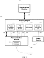
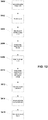
- FIG. 1 shows a high-level diagram of an echocardiographic system and catheter.
- the system comprises an imaging engine 3100 and a patient interface module (PIM) 2000.
- the imaging engine 3100 is the central component of the system and performs all image generation, display, and control of the system components.
- the imaging engine 3100 comprises a general processing unit 3110, a digital signal processing (DSP) module 3120, and a PIM interface module 3130.
- the PIM 2000 is in mechanical and electrical communication with an echocardiographic catheter 1000.
- a catheter is a common medical device comprising a flexible tubular body having a proximal end and a distal end.
- a catheter configured in accordance with an embodiment of the present invention may comprise an outer tube having a proximal end, an inner sheath slidingly received within the outer tube and extending distally from the outer tube, and a rotatable shaft (or drive cable) extending from the proximal end of the outer tube to within the inner sheath.
- the rotatable shaft is axially fixed with respect to the outer tube and is axially moveable within and with respect to the inner sheath.
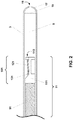
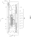
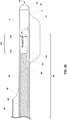
- FIG. 2 shows a distal section of a catheter comprising a distal shaft 3 having an imaging lumen 5 wherein an ultrasound imaging core 11 is positioned.
- the distal section is generally formed by extrusion of thermoplastics such as polyethylene or nylon.
- the distal shaft may also be formed of more than one layer of thermoplastics.
- the distal section further comprises a septum 15, an atraumatic distal tip 17, and a septum puncture port 19.
- the septum 15 may be comprised of a polymer material such as a room-temperature vulcanizing (RTV) silicone.
- RTV room-temperature vulcanizing
- a syringe needle (not shown) is inserted through the septum puncture port 19 and punctures the septum 15 to fill the distal sheath lumen 5 with an ultrasonically transparent fluid such as a sterile saline solution.
- an ultrasonically transparent fluid such as a sterile saline solution.
- the septum 15 seals itself.
- the use of a self-sealing septum prevents the pulling of fluids, such as blood or air, into the distal sheath as the imaging core 11 translates towards the proximal end.
- the imaging core 11 comprises a drive cable 91 attached to a distal housing assembly 101 .
- the distal housing assembly 101 comprises a distal housing 111, a transducer 121, and a transmission line 131.
- a distal housing 111 further comprises a distal opening 113 that facilitates fluid flow across the face of the transducer stack 121.
- the distal housing is described in additional detail in United States Patent Application Serial No. 12/330,308 the complete disclosure of which is hereby incorporated herein by reference.
- the distal shaft 3 comprises an elongated tube having at least one layer.
- the distal shaft can be tapered or straight.
- the distal shaft may be a straight tube having an outer diameter in the range of 0.080" to 0.350" for intracardiac and transesophageal catheters.
- the outer diameter may be more generally 10 Fr (0.131") or smaller for intracardiac catheters.
- Intracardiac catheters having profiles 8 Fr (0.105") or smaller may be more acceptable to deliver via a transseptal route to the left atrium wherein imaging performance may be better for AF ablation guidance than from the right atrium.
- the outer diameter may be more generally between 12 Fr (0.158") and 25 Fr (0.328”) for transesophageal catheters that can be delivered transnasally.
- the drive cable 91 generally comprises at least one single or multi-filar stainless steel or similar material round, square or flat wire coil with an outer diameter generally in the range 0.10 mm to 3.50 mm.
- the elongation and compression of the drive cable 91 during acceleration must be minimized to insure accurate positioning.
- the drive cable 91 should also minimize non-uniform rotation of the imaging core 11.
- the transducer stack 121 operates over frequency ranges of 5 MHz to 60 MHz, generally between 5 MHz and 20 MHz for intracardiac and transesophageal imaging.
- the transducer stack 121 comprises at least a piezoelectric layer.
- the transducer stack 121 generally further comprises conductive layers, at least one matching layer, and a backing layer.
- Transducer stacks for imaging catheters are known to those skilled in the art.
- An exemplary transducer for an 8 Fr sized catheter has an aperture of approximately 1.6 mm by 2.4 mm and has a focal length between 1 cm and 4 cm, generally between 2 cm and 3 cm. Methods to focus transducers are known to those skilled in the art of transducer fabrication.
- a transmission line 131 electrically connects the transducer stack 121 to transceiver electronics housed in the patient interface module.
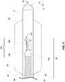
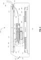
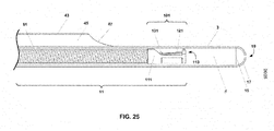
- FIG. 3 shows a side view of an embodiment of the distal section of the catheter comprising a balloon envelope 70, an inflation lumen 60, an inflation port 62, and an ultrasonic imaging core 10.
- the ultrasonic imaging core 10 comprises a drive cable 90 and a distal housing assembly 100 further comprising a distal housing 110, a transducer stack 120, and a transmission line 130.
- the distal housing 110 further comprises a distal opening 112 that facilitates fluid flow across the face of the transducer stack.
- the transducer stack 120 can be focused or unfocused.
- An exemplary transducer for a 15 Fr sized catheter has a circular aperture of up to approximately 4.2 mm and has a focal length between 1 cm and 4 cm, generally between 2 cm and 3 cm. Methods to focus transducers are known to those skilled in the art of transducer fabrication.
- the distal section of the balloon imaging catheter further comprises a sheath 2, a distal sheath lumen 4, a septum 15, an atraumatic distal tip 16, and a septum puncture port 18.
- the septum 15 may be comprised of a polymer material such as a room-temperature vulcanizing (RTV) silicone.
- RTV room-temperature vulcanizing
- a syringe needle (not shown) is inserted through the septum puncture port 18 and punctures the septum 15 to fill the distal sheath lumen 4 with an ultrasonically transparent fluid such as a sterile saline solution.
- an ultrasonically transparent fluid such as a sterile saline solution.
- the septum 15 seals itself.
- the use of a self-sealing septum prevents the pulling of fluids such as air into the distal sheath as the imaging core 10 translates towards the proximal end.
- the balloon catheter is sufficiently small, generally 15 Fr or smaller, such that the esophagus is accessed by a nasal route.
- the balloon envelope 70 may be formed of a compliant polymer blend such as polyethylene/EVA and is attached, generally by bonding or fusing, to the distal catheter sheath section proximal and distal to the inflation port.
- the balloon assembly may be 2 cm to 10 cm in length, generally 6 cm.
- the balloon envelope 70 may be inflated using an ultrasonically transparent fluid, such as a sterile saline solution.
- the balloon can be inflated up to 4 cm in diameter, generally between 2 cm and 3 cm. The inflated balloon facilitates imaging of the esophageal wall and cardiac structures.
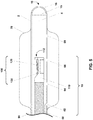
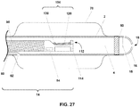
- the distal section comprises a balloon envelope 70 , an inflation lumen 60 , an inflation port 62, a deflation lumen 61, a deflation port 63, and an ultrasonic imaging core 10.
- the ultrasonic imaging core 10 comprises a drive cable 90 and a distal housing assembly 100 further comprising a distal housing 110, a transducer stack 120, and a transmission line 130.
- the distal housing 110 further comprises a distal opening 112 that facilitates fluid flow across the face of the transducer stack.
- the transducer stack 120 can be focused or unfocused.
- An exemplary transducer for a 15 Fr sized catheter has a circular aperture of up to approximately 4.2 mm and has a focal length between 1 cm and 4 cm, generally between 2 cm and 3 cm. Methods to focus transducers are known to those skilled in the art of transducer fabrication.
- the distal section of the balloon imaging catheter further comprises a sheath 2, a distal sheath lumen 4, a septum 15, an atraumatic distal tip 16, and a septum puncture port 18.
- the septum 15 may be comprised of a polymer material such as a room-temperature vulcanizing (RTV) silicone.
- RTV room-temperature vulcanizing
- a syringe needle (not shown) is inserted through the septum puncture port 18 and punctures the septum 15 to fill the distal sheath lumen 4 with an ultrasonically transparent fluid such as a sterile saline solution.
- an ultrasonically transparent fluid such as a sterile saline solution.
- the balloon catheter is sufficiently small, generally 15 Fr or smaller, such that the esophagus is accessed by a nasal route.
- the balloon envelope 70 is formed of a compliant polymer blend such as polyethylene/EVA and is attached, generally by bonding or fusing, to the distal catheter sheath section proximal and distal to the inflation port 62.
- the balloon assembly may be 2 cm to 10 cm in length, generally 6 cm.
- the balloon envelope 70 may be inflated using an ultrasonically transparent fluid, such as a sterile saline solution.
- the balloon can be inflated up to 4 cm in diameter, generally between 2 cm and 3 cm. The inflated balloon facilitates imaging of the esophageal wall and cardiac structures.
- An active inflation/deflation loop enables circulation of a sterile saline solution.
- the circulating saline can potentially be used to remove heat at the esophageal wall and prevent the formation of an atrio-esophageal fistula.
- the distal section comprises a balloon envelope 70, an inflation lumen 60, an inflation port 62, and an ultrasonic imaging core 10.
- the ultrasonic imaging core 10 comprises a drive cable 90 and a distal housing assembly 100 further comprising a distal housing 110, a transducer stack 120, and a transmission line 130.
- the distal housing 110 further comprises a distal opening 112 that facilitates fluid flow across the face of the transducer stack.
- the transducer stack 120 can be focused or unfocused.
- An exemplary transducer for a 15 Fr sized catheter has a circular aperture of up to approximately 4.2 mm and has a focal length between 1 cm and 4 cm, generally between 2 cm and 3 cm. Methods to focus transducers are known to those skilled in the art of transducer fabrication.
- the distal section of the balloon imaging catheter further comprises a sheath 2, a distal sheath lumen 4, a septum 15, an atraumatic distal tip 16, and a septum puncture port 18.
- the septum 15 may be comprised of a polymer material such as a room-temperature vulcanizing (RTV) silicone.
- RTV room-temperature vulcanizing
- a syringe needle (not shown) is inserted through the septum puncture port 18 and punctures the septum 15 to fill the distal sheath lumen 4 with an ultrasonically transparent fluid such as a sterile saline solution.
- an ultrasonically transparent fluid such as a sterile saline solution.
- the balloon catheter is sufficiently small, generally 15 Fr or smaller, such that the esophagus is accessed by a nasal route.
- the balloon envelope 70 may be formed of a compliant polymer blend such as polyethylene/EVA and is attached, generally by bonding or fusing, to the distal catheter sheath section proximal and distal to the inflation port 62.
- the balloon assembly may be 2 cm to 10 cm in length, generally 6 cm.
- the balloon envelope 70 may be inflated using an ultrasonically transparent fluid, such as a sterile saline solution.
- the balloon can be inflated up to 4 cm in diameter, generally between 2 cm and 3 cm. The inflated balloon facilitates imaging of the esophageal wall and cardiac structures.
- Fluid exchange ports 64, 66 , 68 between the distal shaft lumen 4 and interior of the balloon envelope enable exchange of the ultrasonically transparent fluid as the imaging core 10 is advanced and retracted.
- the fluid exchange ports effectively provide a fluid reservoir that prevents the potential generation of negative pressures as the imaging core 10 is retracted within the distal section sheath 2.
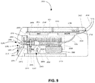
- the distal section of the catheter comprises a balloon envelope 72, an inflation lumen 60, an inflation port 62, and an ultrasonic imaging core 10.
- the ultrasonic imaging core 10 comprises a drive cable 90 and a distal housing assembly 100 further comprising a distal housing 110, a transducer stack 120, and a transmission line 130.
- the distal housing 110 further comprises a distal opening 112 that facilitates fluid flow across the face of the transducer stack.
- the transducer stack 120 can be focused or unfocused.
- An exemplary transducer for a 15 Fr sized catheter has a circular aperture of up to approximately 4.2 mm and has a focal length between 1 cm and 4 cm, generally between 2 cm and 3 cm. Methods to focus transducers are known to those skilled in the art of transducer fabrication.
- the distal section of the balloon imaging catheter further comprises a sheath 2, a distal sheath lumen 4, a septum 15, an atraumatic distal tip 16, and a septum puncture port 18.
- the septum 15 may be comprised of a polymer material such as a room-temperature vulcanizing (RTV) silicone.
- RTV room-temperature vulcanizing
- a syringe needle (not shown) is inserted through the septum puncture port 18 and punctures the septum 15 to fill the distal sheath lumen 4 with an ultrasonically transparent fluid such as a sterile saline solution.
- an ultrasonically transparent fluid such as a sterile saline solution.
- the distal sheath 2 is coupled to the esophageal wall by use of an ultrasonic couplant such as an ultrasonic gel couplant.
- the catheter is held in position relative to the esophageal wall by inflation of the balloon.
- the balloon expands typically to the side of the catheter distal from the heart.
- the balloon catheter is sufficiently small, generally 15 Fr or smaller, such that the esophagus is accessed by a nasal route.
- the balloon envelope 72 may be formed of a compliant polymer blend such as polyethylene/EVA and is attached, generally by bonding or fusing, to the distal catheter sheath section proximal and distal to the inflation port 62.
- the balloon assembly may be 2 cm to 10 cm in length, generally 6 cm.
- the balloon envelope 72 may be inflated using a fluid, such as a radio-opaque contrast medium, sterile saline solution, or mixture thereof.
- a fluid such as a radio-opaque contrast medium, sterile saline solution, or mixture thereof.
- the fluid is not required to be ultrasonically transparent, because the inflation balloon is posterior to the imaging core and esophageal wall.
- the inflated balloon facilitates imaging of the esophageal wall and cardiac structures.
- the patient interface module is the electro-mechanical interface between the catheter and the imaging engine.
- the patient interface module contains the ultrasound generator, receiver, and scanning mechanism.
- FIG. 7 shows a side view of one embodiment of the patient interface module 2000.
- the patient interface module 2000 is in mechanical and electrical communication with the ultrasound imaging core (not shown) of the imaging catheter.
- the patient interface module 2000 comprises means for linear translation and rotation of the ultrasound imaging core.
- the proximal end of the telescoping section of the catheter is attached to an anchor mount 2032 .
- a rotator 2602 mechanically and electrically couples to the proximal end of the catheter imaging core and enables both rotation and linear translation of the catheter imaging core.
- the patient interface module 2000 further comprises a power board 2100, a transceiver (XCVR) board 2200, a motion control (M/C) module 2300, and a linear position sensing array 2420.
- the power board 2100 is in electrical communication (not shown) with the transceiver board 2200 , the motion control module 2300, and a linear position sensing array 2420 .
- the motion control module 2300 comprises electronics that are in electrical communication 2302, 2304, 2306, 2308 with a linear piezomotor 2402 , the linear position sensing array 2420, a rotational motor 2502, and a rotational encoder reader 2516.
- the motion control module 2300 is additionally in electrical communication 2310, 3050 with the imaging engine (not shown) and provides position information.
- the motion control module 2300 may still additionally be in electrical communication with a set of patient interface module operation control buttons (not shown) which are located on an external surface of the patient interface module.
- the linear piezomotor comprises a motor housing 2402 , a rod 2406, and flat springs 2408, 2410.
- Advantages of piezomotors comprise low mass, rapid acceleration and deceleration, bidirectional translation (or cycling), and high velocities (up to 450 mm/s).
- the piezomotor housing 2402, a translation stage 2490, a rotational motor 2502, and a mounting block 2510 are rigidly fixed.
- the piezomotor housing 2402 and fixedly attached components such as the translation stage 2490 move along the rod 2406.
- the rotational motor 2502 is mechanically coupled to first and second gears 2506, 2508. Alternatively, the rotational motor 2502 may be mechanically coupled to first and second pulleys.
- the rotational motor 2502 enables continuous rotation of the ultrasound imaging core. Rotational motors operate at up to at least 8000 revolutions per minute (RPM).
- the second gear 2508 is fixedly attached to a drive shaft 2604.
- the drive shaft further comprises the rotator 2602.
- the drive shaft 2604 is housed within the mounting block 2510.
- the mounting block may be machined or cast from a light-weight material, such as aluminum or titanium, and may additionally provide electrical shielding.
- An encoder wheel 2514 is also fixedly attached to the drive shaft 2604 whereupon an encoder reader 2516 can read the position of the encoder wheel 2514.
- the encoder wheel 2514 and encoder reader 2516 enable tracking of the rotational position of the drive shaft 2604.
- the linear position sensing system comprises an array 2420 of anisotropic magneto-resistive (AMR) sensors 2422 - 2450 and a permanent magnet 2404.
- the permanent magnet 2404 is fixedly attached to the piezomotor housing 2402.
- the array 2420 enables accurate and precise position sensing of the permanent magnet 2404.
- the relative axial position of distal housing and transducer stack of the catheter imaging core can be determined, because the catheter imaging core is mechanically coupled to the piezomotor housing 2402 and permanent magnet 2404.
- the AMR sensors are positioned periodically along the travel range and offset from the magnet.
- the spacing between the AMR sensors can be up to 8 mm.
- AMR sensors can be added to extend the travel range of position sensing.
- the offset distance of the sensors to the permanent magnet depends on the field strength at the pole face of the magnet.
- the offset distance can be up to 0.25" for ceramic and AlNiCo magnets and up to 0.5" for rare earth magnets, such as neodymium types.
- Resolution of position is approximately 0.002" (50 ⁇ m) with accuracy better than 1 % with an AMR sensor spacing of 8 mm. Resolution and accuracy can be improved by reducing sensor spacing.
- the transceiver board 2200 comprises analog electronics for transmission and reception of the ultrasound signals.
- the transceiver board 2200 is in electrical communication 2022, 3050 with the imaging engine (not shown).
- the transceiver board 2200 is additionally in electrical communication 2202 with a liquid metal rotary coupler 2610 and the drive shaft 2604.
- the electrical components of the drive shaft 2604 comprise an electrical jack 2608, a transformer 2606, and an electrical contact assembly (not shown) within the rotator 2602.
- the electrical contact assembly is in electrical communication with the transmission line of the catheter imaging core.
- the patient interface module 2000 is in mechanical and electrical communication with the ultrasound imaging core (not shown) of the imaging catheter.
- the patient interface module 2000 comprises means for linear translation and rotation of the ultrasound imaging core.
- the proximal end of the telescoping section of the catheter is attached to an anchor mount 2032.
- a rotator 2602 mechanically couples to the proximal end of the catheter imaging core and enables both rotation and linear translation of the catheter imaging core.
- the patient interface module 2000 further comprises a power board 2100, a transceiver (XCVR) board 2200, and a motion control (M/C) module 2300.
- the power board 2100 is in electrical communication (not shown) with the transceiver board 2200 and the motion control module 2300.
- the motion control module 2300 comprises electronics that are in electrical communication 2305, 2306, 2308 with a linear piezomotor and encoder system 2460, a rotational motor 2502, and a rotational encoder reader 2516.
- the motion control module 2300 is additionally in electrical communication 2310, 3050 with the imaging engine (not shown) and provides position information.
- the motion control module 2300 may still additionally be in electrical communication with a set of patient interface module operation control buttons (not shown) which are located on an external surface of the patient interface module.
- the linear piezomotor comprises a motor housing 2460, a rod 2406, and flat springs 2408, 2410. Advantages of piezomotors comprise low mass, rapid acceleration and deceleration, bidirectional translation (or cycling), and high velocities (up to 450 mm/s).
- the linear piezomotor and encoder system housing 2460, a translation stage 2490, a rotational motor 2502, and a mounting block 2510 are rigidly fixed.
- the linear piezomotor and encoder system housing 2460 and fixedly attached components such as the translation stage 2490 move along the rod 2406.
- the rotational motor 2502 is mechanically coupled to first and second gears 2506, 2508. Alternatively, the rotational motor 2502 may be mechanically coupled to first and second pulleys.
- the rotational motor 2502 enables continuous rotation of the ultrasound imaging core. Rotational motors operate at up to at least 8000 revolutions per minute (RPM).
- the second gear 2508 is fixedly attached to a drive shaft 2604.
- the drive shaft further comprises the rotator 2602.
- the linear encoder system enables tracking of the axial position of the drive shaft 2604.
- the drive shaft 2604 is housed within the mounting block 2510.
- the mounting block may be machined or cast from a light-weight material, such as aluminum or titanium, and may additionally provide electrical shielding.
- An encoder wheel 2514 is also fixedly attached to the drive shaft 2604 whereupon an encoder reader 2516 can read the position of the encoder wheel 2514.
- the encoder wheel 2514 and encoder reader 2516 enable tracking of the rotational position of the drive shaft 2604.
- the transceiver board 2200 comprises analog electronics for transmission and reception of the ultrasound signals.
- the transceiver board 2200 is in electrical communication 2022, 3050 with the imaging engine (not shown).
- the transceiver board 2200 is additionally in electrical communication 2202 with a liquid metal rotary coupler 2610 and the drive shaft 2604.
- the electrical components of the drive shaft 2604 comprise an electrical jack 2608, a transformer 2606, and an electrical contact assembly (not shown) within the rotator 2602.
- the electrical contact assembly is in electrical communication with the transmission line of the catheter imaging core.
- the patient interface module 2000 is in mechanical and electrical communication with the ultrasound imaging core (not shown) of the imaging catheter.
- the patient interface module 2000 comprises means for linear translation and rotation of the ultrasound imaging core.
- the proximal end of the telescoping section of the catheter is attached to an anchor mount 2032.
- a drive shaft 2603 rotator 2602 mechanically and electrically couples to the proximal end of the catheter imaging core and enables both rotation and linear translation of the catheter imaging core.
- the patient interface module 2000 further comprises a power board 2100, a transceiver (XCVR) board 2200, and a motion control (M/C) module 2300.
- the power board 2100 is in electrical communication (not shown) with the transceiver board 2200 and the motion control module 2300.
- the motion control module 2300 comprises electronics that are in electrical communication 2306, 2308 with a rotational motor 2502 and a rotational encoder reader 2516 .
- the motion control module 2300 is additionally in electrical communication 2310, 3050 with the imaging engine (not shown) and provides position information.
- the motion control module 2300 may further be in electrical communication with a set of patient interface module operation control buttons (not shown) which are located on an external surface of the patient interface module.
- the relative linear position of a low-friction translation stage 2478 and catheter imaging core is determined from the rotational position.
- a linear position sensor such as the linear position sensing system as illustrated in FIG. 3 , can be included to reduce ambiguity of longitudinal position of the catheter imaging core.
- the rotational motor 2502 is mechanically coupled to a first pinion gear 2505.
- the first pinion gear engages a first gear 2476.
- the first gear 2476 engages a second pinion gear 2507.
- the first gear 2476 is also fixedly attached to a first end 2473 of a linkage arm 2472.
- a second end 2471 of the linkage arm 2472 is fixedly attached to a linkage arm mount 2470.
- the first gear 2476 and rotational motor 2502 are fixedly attached to a low-friction translation stage 2478.
- the second pinion gear 2507 is fixedly attached to a second gear 2509.
- the second gear 2509 engages a third gear 2511 that is fixedly attached to the drive shaft 2603.
- first and second pulleys can be used in place of the second and third gears 2507, 2509.
- the rotational motor 2502 enables continuous rotation and translation of the ultrasound imaging core.
- the first pinion gear 2505 rotates, the first gear 2476 and first end 2473 of the linkage arm 2472 rotate about the axis of rotation of the first gear 2476.
- the cyclical motion of the linkage arm 2472 causes the low-friction translation stage 2478 to slide back and forth.
- the back-and-forth motion of the low-friction translation stage 2478 causes the imaging core to correspondingly translate back and forth, or cycle in a longitudinal direction.
- the range of linear translation will be determined by the distance of the first end 2473 of the linkage arm 2472 to the axis of rotation of the first gear 2476.
- Advantages of a gear and linkage arm system compared to embodiments comprising a linear translation motor include in part a simpler design, lower weight, and lower cost.
- the drive shaft 2603 is housed within the mounting block 2511.
- the mounting block may be machined or cast from a light-weight material, such as aluminum or titanium, and may additionally provide electrical shielding.
- An encoder wheel 2514 is also fixedly attached to the drive shaft 2603 whereupon an encoder reader 2516 can read the position of the encoder wheel 2514.
- the encoder wheel 2514 and encoder reader 2516 enable tracking of the rotational position of the drive shaft 2604.
- the transceiver board 2200 comprises analog electronics for transmission and reception of the ultrasound signals.
- the transceiver board 2200 is in electrical communication 2022, 3050 with the imaging engine (not shown).
- the transceiver board 2200 is additionally in electrical communication 2202 with a liquid metal rotary coupler 2610 and the drive shaft 2603.
- the electrical components of the drive shaft 2604 comprise an electrical jack 2608, a transformer 2606, and an electrical contact assembly (not shown) within the rotator 2602.
- the electrical contact assembly is in electrical communication with the transmission line of the catheter imaging core.
- a rapid linear translation and rotation of the ultrasound imaging core combined with the accurate position sensing enables volumetric scanning of moving structures such as cardiac structures.
- Cyclical linear translation enables continuous real-time imaging of a volume of interest.
- Alternative transducer configurations can provide additional benefits for image guidance of cardiac ablation procedures.
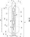
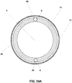
- the distal section of the catheter comprises a balloon envelope 70, an inflation lumen 60, an inflation port 62, and an ultrasonic imaging core 40.
- the ultrasonic imaging core 40 comprises a drive cable 490 and a distal housing assembly 400.
- the distal housing assembly 400 comprises four transducer housings 412, 414, 416, 418, four transducer stacks 422, 424, 426, 428, and three flexible housing couplings 404, 406, 408.
- the four transducer housings further comprise distal openings 442, 444, 446, 448 that facilitate fluid flow across the faces of the transducer stacks.
- the individual transducers and housings are substantially similar in configuration to that shown in FIG. 2 .
- the multiple transducer assembly can be fabricated according to several techniques.
- the multiple transducer housings and couplings can be fabricated from a single stainless steel hypotube.
- the transducer housings provide rigid support to the individual transducer assemblies by means of a fitted slot.
- the couplings are spiral-cut sections of the hypotube and balance axial rigidity and bending flexibility for the multiple transducer assembly.
- the pitch of the spiral cut can be constant or can be varied depending upon the target stiffness characteristics. The pitch may be increased for less flexibility or decreased for more flexibility. Some flexibility facilitates transnasal positioning of the catheter.
- the transducer housings are approximately 4 mm in length, the transducer couplings are approximately 6 mm in length, and the transducer diameters are 2.5 mm.
- the pitch of spiral-cut coupling is typically 1 mm having 100 micron kerfs.
- the transducer housing couplings can be separate materials such as stainless steel drive cables that are attached to the transducer housings.
- the directions of nearest-neighbor transducers are offset by 90° relative to each other.
- the first transducer stack 422 faces the top of the drawing sheet
- the second transducer stack 424 faces into the drawing sheet
- the third transducer stack 426 faces the bottom of the drawing sheet
- the fourth transducer stack 428 faces out of the drawing sheet.
- the rotational offsets of the multiple transducers minimize potential cross interference of tissue-scattered ultrasonic energy between transducers.
- Advantages of a multiple transducer assembly comprise increased 3D imaging frame rate.
- the cyclic linear translation travel range of the transducer assembly can be decreased according to the number of transducers and transducer separation distance.
- the complete 3D image can be formed from the smaller 3D images from the individual transducers. For the exemplary configuration shown in FIG. 10 and an image volume comprising a 4 cm height, a travel path of approximately 1 cm is required. This leads to an increase in frame rate by a factor of approximately four compared to that of a single element trans
- the distal section of the balloon imaging catheter further comprises a sheath 2, a distal sheath lumen 4, a septum 15, an atraumatic distal tip 16, and a septum puncture port 18.
- the septum 15 is comprised of a polymer material such as a room-temperature vulcanizing (RTV) silicone.
- RTV room-temperature vulcanizing
- a syringe needle (not shown) is inserted through the septum puncture port 18 and punctures the septum 15 to fill the distal sheath lumen 4 with an ultrasonically transparent fluid such as a sterile saline solution.
- an ultrasonically transparent fluid such as a sterile saline solution.
- the balloon catheter is sufficiently small, generally 15 Fr or smaller, such that the esophagus is accessed by a nasal route.
- the balloon envelope 70 is formed of a compliant polymer blend such as polyethylene/EVA and is attached, generally by bonding or fusing, to the distal catheter sheath section proximal and distal to the inflation port 62.
- the balloon assembly is 2 cm to 10 cm in length, generally 6 cm.
- the balloon envelope 70 is inflated using an ultrasonically transparent fluid, such as a sterile saline solution.
- the balloon can be inflated up to 4 cm in diameter, generally between 2 cm and 3 cm. The inflated balloon facilitates imaging of the esophageal wall and cardiac structures.
- FIG. 11 an exemplary set of processing stages are shown for identifying susceptible substrates in the left atrial wall by means of a transesophageal echocardiography catheter and system as described heretofore.
- the image data is first acquired in step 3200.
- the cardiac wall is then segmented in step 3202 from the surrounding tissue and devices, including for example blood in the left atrial chamber, the esophageal wall, the fat pad, and ablation devices.
- the segmented image data is then, in step 3204 , compensated for system and transducer effects comprising range-dependent amplitude and frequency variations.
- Tissue classifiers are then calculated in step 3206 from segmented image data corresponding to the left atrial wall.
- Tissue classifiers can be calculated by analysis of the image data and is referred to as time-domain analysis. Tissue classifiers can also be calculated by analysis of the spectral properties of the image data and is referred to as frequency-domain analysis. Exemplary tissue classifiers may comprise integrated backscatter and slope-of-attenuation which are known to those skilled in the art of ultrasonic tissue classification.
- tissue classification One approach to tissue classification that is known to those skilled in the art is to select volumetric regions of interest (ROIs) comprised of samples from neighboring image vectors. The number of samples and number of vectors is instrument and application dependent.
- ROIs volumetric regions of interest
- a ROI from image data that is approximately 1 mm ⁇ 1 mm ⁇ 1 mm in volume at a range of 2 cm from a multiple transducer assembly as illustrated in FIG. 10 requires 5 vectors ⁇ 129 samples ⁇ 1 slice assuming 0.7° in-plane vector spacing, 100 ⁇ 10 6 samples/s sampling rate, and a 2 mm slice thickness.
- Tissue classifiers are then calculated from the compensated image data.
- Susceptible substrates in the left atrial wall are identified in step 3208 by use of the calculated tissue classifiers.
- Susceptible substrates are known to be characterized by an increased interstitial fibrotic content.
- a primary component of the interstitial fibrosis is collagen, and collagen can be identified by its ultrasonic properties.
- the differentiation of susceptible substrates from normal left atrial wall is determined empirically.
- Exemplary ultrasound tissue classifiers such as integrated backscatter, slope of attenuation, and speed of sound correlate with collagen content.
- the variation of the tissue classifiers during the heart cycle can also be used to identify susceptible substrates.
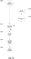
- FIG. 12 illustrates an exemplary set of processing stages for titrating ablation, indicating potentially adverse events, and identifying necrosed tissue in the left atrial wall that develop as a result of cardiac ablation procedures.
- Baseline image data of the left atrial wall are acquired in step 3400 prior to ablation in step 3402.
- Tissue can be ablated by multiple technologies, including RF ablation and cryo-ablation.
- Post-ablation image data are acquired in step 3404 and evaluated at each ablation site. Pre- and post-ablation image data are co-registered to insure that the same tissue volumes are analyzed. Compensation for motion is provided in step 3406 between image acquisitions as required before co-registration.
- the left atrial wall is then segmented in step 3408 from the surrounding tissue and devices, including for example blood in the left atrial chamber, the esophageal wall, the fat pad, and ablation devices.
- the segmented image data is then compensated in step 3410 for system and transducer effects comprising range-dependent amplitude and frequency variations.
- Tissue classifiers are then calculated in step 3412 from segmented image data corresponding to the left atrial wall. Calculations of integrated backscatter, thermal strain, and slope of attenuation are known to those skilled in the art.
- Potential adverse events are indicated in step 3414 by means of the calculated tissue classifiers. Adverse event indicators may include microbubble formation, overheating of tissues such as the esophageal wall, and thrombus formation.
- tissue classifiers corresponding to potential adverse events are determined empirically.
- Necrosed tissues in the left atrial wall are also identified in step 3416 by means of the calculated tissue classifiers. Necrotic tissue is known to be characterized in part by increased echogenicity. For patients that are in sinus rhythm, the variation of the tissue classifiers during the heart cycle can also be used to identify necrosed tissue. The differentiation of necrosed tissue from viable left atrial wall is determined empirically.
- the rapid linear translation and rotation of an ultrasound imaging core comprising multiple transducers can increase volumetric imaging rate.
- Specific imaging algorithms facilitate image guidance for cardiac ablation procedures.
- Still other configurations of multiple transducers and arrays enable real-time synthetic aperture imaging wherein a synthetic aperture comprises a combination of multiple physical (or real) apertures.
- Synthetic aperture imaging enables improved image quality. Cyclical linear translation enables continuous real-time 3D synthetic aperture imaging of a volume of interest.
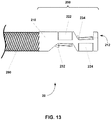
- the imaging core 20 comprises a drive cable 290 and a distal housing assembly 200.
- the distal housing assembly 200 comprises a transducer housing 210, a first transducer stack 222, and a second transducer stack 224.
- the transducer housing 210 further comprises a distal opening 212 that facilitates fluid flow across the face of the second transducer stack 224.
- the transducer housing 210 comprises a laser-cut stainless steel hypotube wherein the first and second transducer stacks 222, 224 are positioned facing in opposing directions.
- the edge-to-edge inter-element spacing is designed to satisfy synthetic aperture imaging requirements that depend on transducer width, linear translation velocity, rotational velocity, and transmit sequence.
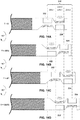
- FIGS. 14A - 14D one embodiment of a transmit and motion sequence is shown for the two transducer imaging core shown in FIG. 13 .
- the first and second transducer stacks 222, 224 have substantially the same physical properties, including aperture size and imaging frequency.
- a synthetic aperture 220 is formed as the transmit and motion sequence adds the width of a transducer aperture for each rotation of the imaging core. A full 360° rotation of the imaging core occurs in a time ⁇ T. The inter-element spacing is half the transducer aperture width.
- the second transducer stack 224 is fired first (224-1).
- the imaging core After the imaging core has rotated 180° ( ⁇ radians), it has translated distally by half a transducer aperture width as seen in FIG. 14B .
- the first transducer stack 222 then begins firing (222-1).
- the imaging core rotates another 180° and translates distally by half a transducer aperture width to the position shown in FIG. 14C . In one full rotation, the imaging core has translated the width of a transducer.
- the distal transducer then begins its second firing sequence (224-2) as seen in FIG. 14D .
- Each additional rotation of the imaging core increases the width of the synthetic aperture by a transducer width and enables signal averaging for overlapping subapertures.
- the effective azimuthal resolution of the synthetic aperture improves as the aperture widens.
- the transducer widths, inter-element spacing, linear translation velocity, rotational velocity, and transmit sequence can be varied to modify the synthetic aperture size, the number of elements of the synthetic aperture, and the extent of subaperture overlap
- a 4 cm field of view may be suitable for intracardiac and transesophageal imaging.
- the two transducer configuration of the imaging core of FIGS. 13 and 14 are well suited to imaging over a 180° sector rather than a full 360° sector as is done for mechanically rotating imaging catheters used for intravascular ultrasound applications.
- Each transmit-receive sequence requires approximately 50 ⁇ s to acquire.
- An image frame comprising a 180° sector (angular width) and 256 vectors requires approximately 13 ms to acquire.
- a translation speed of 20 mm/s and rotation speed of 1800 RPM achieves 60 2D frames per second.
- Each additional rotation acquires two image frames within approximately 25 ms and extends the width of the synthetic aperture by 1.6 mm.
- the rapid cyclical translation enables continuous 3D image frame rates of approximately two 3D images per second.
- the 3D image frame rate can be increased by reducing the image range and travel distance.
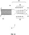
- the imaging core 50 comprises a drive cable 590 and a distal housing assembly 500.
- the distal housing assembly comprises a transducer housing 510 and four transducer stacks 522 , 524, 526, 528.
- the four transducer assembly design is well suited for imaging applications that generally display 90° sector frames.
- the transducer widths, inter-element spacings, linear translation velocity, rotational velocity, and transmit sequence can be varied to modify the synthetic aperture size, the number of elements of the synthetic aperture, and the extent of subaperture overlap.
- a synthetic aperture with the width of five transducer widths and no subaperture overlap can be achieved when the inter-element spacing is one-half of a transducer width, the imaging core translates the inter-element spacing for each 90° rotation, and the transducers fire in order from the first transducer stack (most distal) 528, the second transducer stack 526, the third transducer stack 524, and then the fourth transducer stack (most proximal) 522.
- the imaging core 90 comprises a drive cable 990 and a distal housing assembly 900.
- the distal housing assembly 900 comprises a transducer housing 910, a first four element transducer array 920, and a second four element transducer array 930.
- the first transducer array 920 comprises four independent elements 922, 924, 926, 928 that are substantially mechanically isolated by kerfs.
- the transducer array 930 comprises four independent elements 932 , 934, 936, 938 that are substantially mechanically isolated by kerfs.
- Each transducer element is attached, generally by soldering or conductive adhesive, to a transmission line (not shown).
- each transducer array can be operated independently.
- the first and second transducer arrays 920, 930 can further be operated independently if there are a sufficient number of signal channels in the imaging engine.
- the first and second transducer arrays 920 , 930 may be multiplexed if signal channels in the imaging engine must be shared.
- the transducer arrays are positioned back-to-back. Each transducer can have a separate backing material. Back-to-back transducers can also share a common backing material.
- the two transducer array assembly 900 can be operated similarly to the two transducer assembly 200 shown in FIG. 13 for continuous, real-time 3D synthetic aperture imaging. Advantages of a transducer array comprise dynamic transmit focusing.
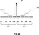
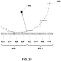
- FIGS. 17A - 17C illustrate an image sequence for generating a synthetic aperture 940 having a width of three times the transducer array width that is acquired in a single rotation of the imaging core.
- a full 360° rotation of the imaging core occurs in a time ⁇ T.
- the first transducer array 920 is fired first ( 920-1 ) over a 180° sector as seen in FIG. 17A .
- the second transducer array 930 then begins firing ( 930-1 ) over a 180° sector as seen in FIG. 17B .
- the imaging core rotates another 180° and translates distally by a transducer array width. In one full rotation, the imaging core has translated the width of two transducer arrays.
- the distal transducer then begins its second firing sequence (920-2) as seen in FIG. 17C .
- a transducer assembly suitable for continuous, real-time 3D synthetic aperture imaging of cardiac structures comprises a four transducer array with element widths of 0.485 mm and kerf sizes of 20 ⁇ m.
- the transducer array width is 2 mm.
- a continuous 3D image frame rate of approximately one 3D image per second is achieved with a rotational speed of 1200 RPM and a linear translation velocity of 40 mm/s.
- a synthetic aperture width of 6 mm comprising 12 elements can be acquired within 50 ms.
- a transducer assembly suitable for continuous, real-time 3D synthetic aperture imaging of cardiac structures comprises a four transducer array with element sizes of approximately 4.2 mm height by 0.5 mm width and kerf sizes of 20 ⁇ m.
- the dimensions of the transducer array are constrained in part by the catheter size.
- the maximum transducer array height in a 15 Fr catheter is approximately 4.2 mm.
- the width of the transducer array can vary from 1 mm to 6 mm, generally 2 mm.
- the kerf width can be as narrow as 5 ⁇ m, but is generally 20 ⁇ m.
- the array size is approximately 4.2 mm height by 2 mm width.
- the imaging core 80 comprises a drive cable 890 and a distal housing assembly 800.
- the distal housing assembly 800 comprises a distal transducer housing 810 and a transducer array 820.
- the transducer array 820 comprises eight transducer elements 822, 824, 826, 828, 830, 832, 834, 836 that are substantially mechanically isolated by kerfs.
- Each transducer element is attached, generally by soldering or conductive adhesive, to a transmission line (not shown).
- the transducer elements of each transducer array can be operated independently.
- the eight element transducer array assembly design is well suited for imaging applications that typically display 360° sector frames, similar to a single element transducer shown in FIG. 2 .
- the independent operation of each transducer element enables dynamic transmit focusing that may provide advantages for image quality compared to single element transducer or synthetic aperture imaging.
- FIG. 19 illustrates an exemplary process for generating a synthetic aperture image.
- the generation and detection of ultrasound energy is known to those skilled in the art.
- the number of subapertures to be acquired depends in part on the size of the transducer array, the size of the targeted synthetic aperture, and potentially time constraints due to tissue motion. For a transducer array having a 2 mm width and a targeted synthetic aperture width of 4 mm, two subapertures are required.
- the process of FIG. 19 initiates with step 3100 where subaperture array image data are acquired. If this is the start of the synthetic aperture imaging process and additional subaperture array image data are to be acquired, it is determined in decision block 3102 that another subaperture array image should be added.
- the imaging core is then rotated in step 3104 and translated in step 3106.
- the second subaperture is acquired with the repeat of step 3100.
- the rotation speed and translation speed depends in part on the transducer array configuration, the maximum imaging range, the vector density, and targeted frame rate.
- the motion speeds further depend on tissue motion. For exemplary case shown in FIG. 14 of the two transducer array assembly 900 having a 2 mm array width, 40 frames per second can be achieved assuming a maximum imaging range of 4 cm, a vector density of 256 scan lines per 180° image sweep, and a rotation speed of 1200 RPM. If no additional subaperture array images need to be acquired, it is determined in decision block 3102 that no additional subaperture array image are to be added to the synthetic aperture.
- Subaperture images are then generated in step 3108. Tissue motion that occurs between subaperture acquisitions is compensated in step 3110. Motion compensation techniques are known to those skilled in the art and comprise block correlation techniques. A synthetic aperture image is then generated in step 3112 from both subaperture image data sets. Image formation comprises apodization and delay-and-sum beamforming techniques that are known to those skilled in the art.
- an ultrasound signal delay profile 940 for the eight element synthetic aperture imaging core 90 of FIG. 16 built from the two transducer array is illustrated.
- Ultrasound signals are first generated and detected by the four elements 922, 924, 926, 928 of the first transducer array 920.
- Ultrasound signals from the first transducer array 920 are stored on a computer-readable medium for subsequent analysis.
- Ultrasound signals are then generated and detected by the four elements 932, 934, 936, 938 of the second transducer array 930.
- Ultrasound signals from the second transducer array 930 are also stored on a computer-readable medium for subsequent analysis.
- the stored ultrasound signals from the first and second transducer arrays 920, 930 are then processed to focus the signals at a predetermined focal spot 950 .
- the end-to-end positioning of the first and second transducer arrays 920, 930 is achieved by precise positioning of the imaging core by rapid linear translation and rotation.
- FIG. 20 illustrates focusing ultrasound signals in a direction perpendicular to the plane of the synthetic aperture.
- Spatial compound imaging techniques may be used to reduce image artifacts due to temperature variations that occur during ablation procedures. Localized changes in the speed of sound due to heating or cooling of tissue by ablation catheters cause ultrasound image artifacts because standard beamformation algorithms assume a constant speed of sound. Spatial compound imaging techniques mitigate the thermoacoustic lens image artifacts by imaging tissue volumes of interest from multiple directions. Imaging directions comprising ultrasound propagation paths with fewer thermal variations generate fewer image artifacts.
- an ultrasound signal delay profile 942 for an eight element synthetic aperture is used to steer ultrasound signals 20° off perpendicular to the face of the synthetic aperture.
- Ultrasound signals are first generated and detected by the four elements 922, 924, 926, 928 of the first transducer array 920.
- Ultrasound signals from the first transducer array 920 are stored on a computer-readable medium for subsequent analysis.
- Ultrasound signals are then generated and detected by the four elements 932, 934, 936, 938 of the second transducer array 930.
- Ultrasound signals from the second transducer array 930 are also stored on a computer-readable medium for subsequent analysis.
- the stored ultrasound signals from the first and second transducer arrays 920, 930 are then processed to focus the signals at a predetermined focal spot 952.
- the end-to-end positioning of the first and second transducer arrays 920, 930 is achieved by precise positioning of the imaging core by rapid linear translation and rotation.
- Spatial compounding combined with rapid linear translation and rotation of the imaging core enables a volume of interest to be insonified from multiple directions.
- An exemplary spatial compound imaging acquisition comprises five imaging directions -10°, -5°, 0°, +5°, and +10° from perpendicular to the face of the eight element synthetic aperture.
- the multiple images acquired at different imaging directions are then combined into a single spatial compound image.
- Spatial compound imaging techniques are known to those skilled in the art. The optimal number of spatial compound angles and aperture size for cardiac ablation monitoring is determined empirically.
- alternative catheter configurations can provide advantages for image guidance of AF ablation procedures.
- alternative embodiments comprise a guidewire receiver lumen to facilitate delivery of the catheter to the anatomical site of interest.
- FIG. 22 shows a distal section of an echocardiography catheter comprising a sheath 51, a distal tip 50, and an imaging core 11.
- the distal sheath 51 is bonded to the distal tip 50.
- the distal tip 50 is a short monorail (or rapid exchange) design adapted to receive a guidewire GW.
- the longitudinal axis of the distal tip 50 is substantially parallel to and offset from the longitudinal axis of the distal shaft 51.
- the imaging core 11 comprises a drive cable 91 attached to a distal housing assembly 101 wherein the distal housing assembly 101 comprises a distal housing 111, a transducer stack 121, and a transmission line 131.
- the distal housing 111 further comprises a distal opening 113 that facilitates fluid flow across the face of the transducer stack 121 .
- the distal tip is described in U.S. Patent Application Ser. No. 12/547,972 .
- FIG. 23 shows a distal section of an echocardiography catheter comprising a long monorail or over-the-wire design.
- the distal section comprises a distal shaft 3 having an imaging lumen 5 wherein an ultrasound imaging core 11 is positioned.
- the distal section further comprises a septum 15, an atraumatic distal tip 17, and a septum puncture port 19.
- the septum 15 may be comprised of a polymer material such as a room-temperature vulcanizing (RTV) silicone.
- RTV room-temperature vulcanizing
- a syringe needle (not shown) may be inserted through the septum puncture port 19 to puncture the septum 15 and fill the distal sheath lumen 5 with an ultrasonically transparent fluid such as a sterile saline solution.
- the septum 15 Upon withdrawal of the syringe needle the septum 15 seals itself.
- the use of a self-sealing septum prevents the pulling of fluids such as air into the distal sheath as the imaging core 11 translates towards the proximal end.
- the imaging core 11 comprises a drive cable 91 attached to a distal housing assembly 101 wherein the distal housing assembly 101 comprises a distal housing 111, a transducer stack 121, and a transmission line 131.
- the distal housing 111 further comprises a distal opening 113 that facilitates fluid flow across the face of the transducer stack 121.
- the distal section still further comprises an additional lumen 59 adapted to receive a guidewire GW.
- FIG. 24A shows a cross section cut of the catheter at a steering ring 80 of the steerable catheter.
- the steering ring 80 is embedded between a first and second thermoplastic layer 70, 72 in the steering segment 30 of the distal section of the catheter sheath.
- the steering section is generally proximal to the balloon and imaging window of the catheter.
- the steering ring may be laser cut from a stainless steel hypotube.
- the stainless steel steering cords 86, 88 extend from the proximal end of the catheter (not shown) to the steering ring 80 through steering cord lumens 6, 8.
- the steering cords are coupled to steering control mechanism (not shown) that enable steering of the catheter tip by the user.
- the steering cords are attached to the steering ring 80, generally by soldering, brazing, or laser welding.
- the steering segment 30 of the catheter is attached to a stiffer proximal section (not shown) that enables bending of the distal section of the catheter.
- the design and operation of steerable catheters are known to those skilled in the art.
- the distal section comprises an imaging core 11 and a working lumen 45.
- the working lumen 45 enables the use of additional devices such as electroanatomic mapping and ablation catheters.
- the exit port 47 of the working lumen is located proximal to the imaging window of the imaging lumen.
- the imaging core 11 comprises a drive cable 91 attached to a distal housing assembly 101 wherein the distal housing assembly 101 comprises a distal housing 111, a transducer stack 121, and a transmission line 131.
- the distal housing 111 further comprises a distal opening 113 that facilitates fluid flow across the face of the transducer stack 121.
- the distal section of the imaging catheter further comprises a sheath 3, a distal sheath lumen 5, a septum 15, an atraumatic distal tip 17, and a septum puncture port 19.
- the septum 15 is comprised of a polymer material such as a room-temperature vulcanizing (RTV) silicone.
- RTV room-temperature vulcanizing
- a syringe needle (not shown) is inserted through the septum puncture port 19 and punctures the septum 15 to fill the distal sheath lumen 5 with an ultrasonically transparent fluid such as a sterile saline solution.
- an ultrasonically transparent fluid such as a sterile saline solution.
- the imaging catheter is sufficiently small, generally 8 Fr or smaller, such that the left atrium is accessed by a transseptal route.
- An intracardiac echocardiography catheter having an additional working lumen can potentially reduce the number of transseptal punctures required for image guidance of AF ablation procedures.
- FIG. 26 a side view of another embodiment of the distal section of a transesophageal echocardiography catheter is shown.
- the distal section of the catheter comprises a balloon envelope 72, an ultrasonic imaging core 10, and a working lumen 44.
- the working lumen 44 enables the use of additional devices such as a steering stylet that may be useful for repositioning the esophagus relative to an ablation catheter during an ablation procedure. The ability to reposition the esophagus can potentially mitigate adverse events such as formation of atrio-esophageal fistula.
- the exit port 46 of the working lumen is located proximal to the imaging window of the imaging lumen.
- the ultrasonic imaging core 10 comprises a drive cable 90 and a distal housing assembly 100 further comprising a distal housing 110, a transducer stack 120, and a transmission line 130.
- the distal housing 110 further comprises a distal opening 112 that facilitates fluid flow across the face of the transducer stack.
- the transducer stack 120 can be focused or unfocused.
- the distal section of the balloon imaging catheter further comprises a sheath 2, a distal sheath lumen 4, a septum 15, an atraumatic distal tip 16, and a septum puncture port 18.
- the septum 15 may be comprised of a polymer material such as a room-temperature vulcanizing (RTV) silicone.
- a syringe needle (not shown) may be inserted through the septum puncture port 18 to puncture the septum 15 and to fill the distal sheath lumen 4 with an ultrasonically transparent fluid such as a sterile saline solution.
- an ultrasonically transparent fluid such as a sterile saline solution.
- the distal sheath 2 is coupled to the esophageal wall by use of an ultrasonic couplant such as an ultrasonic gel couplant.
- the catheter is held in position relative to the esophageal wall by inflation of the balloon.
- the balloon expands typically to the side of the catheter distal from the heart.
- the balloon catheter is sufficiently small, generally 15 Fr or smaller, such that the esophagus may be accessed by a nasal route.
- the balloon envelope 72 is formed of a compliant polymer blend such as polyethylene/EVA and is attached, generally by bonding or fusing, to the distal catheter sheath section proximal and distal to an inflation port 62.
- the balloon assembly is 2 cm to 10 cm in length, generally 6 cm.
- the balloon envelope 72 is inflated using an ultrasonically transparent fluid, such as a sterile saline solution. The inflated balloon facilitates imaging of the esophageal wall and cardiac structures.
- the distal section comprises a balloon envelope 70, an inflation lumen 60, an inflation port 62, and an ultrasonic imaging core 14.
- the ultrasonic imaging core 14 comprises a drive cable 90 and a distal housing assembly 104 further comprising a distal housing 114, a transducer stack 120, and a transmission line 130.
- the distal housing 114 further comprises a distal opening 112 that facilitates fluid flow across the face of the transducer stack.
- the transducer stack 120 can be focused or unfocused.
- An exemplary transducer for a 15 Fr sized catheter has a circular aperture of up to approximately 4.2 mm and has a focal length between 1 cm and 4 cm, generally between 2 cm and 3 cm. Methods to focus transducers are known to those skilled in the art of transducer fabrication.
- the distal housing assembly 104 still further comprises a magnetic sensor 54.
- the magnetic sensor 54 comprises one, two, or three-axis coils with mutually orthogonal windings.
- the sensor detects AC or DC magnetic fields generated by an external transmitter (not shown).
- the sensor output enables tracking of the catheter imaging core by means of an external magnetic tracking system (not shown).
- the distal section of the balloon imaging catheter further comprises a sheath 2, a distal sheath lumen 4, a septum 15, an atraumatic distal tip 16 , a septum puncture port 18, and a radio-opaque marker band 50 .
- the septum 15 may be comprised of a polymer material such as a room-temperature vulcanizing (RTV) silicone.
- RTV room-temperature vulcanizing
- a syringe needle (not shown) may be inserted through the septum puncture port 18 to puncture the septum 15 and to fill the distal sheath lumen 4 with an ultrasonically transparent fluid such as a sterile saline solution.
- an ultrasonically transparent fluid such as a sterile saline solution.
- the balloon catheter is sufficiently small, generally 15 Fr or smaller, such that the esophagus is accessed by a nasal route.
- the balloon envelope 70 is formed of a compliant polymer blend such as polyethylene/EVA and is bonded to the distal catheter sheath section proximal and distal to the inflation port 62.
- the balloon assembly is 2 cm to 10 cm in length, generally 6 cm.
- the balloon envelope 70 is inflated using an ultrasonically transparent fluid, such as a sterile saline solution.
- the balloon can be inflated up to 4 cm in diameter, generally between 2 cm and 3 cm.
- the inflated balloon facilitates imaging of the esophageal wall and cardiac structures.
- the radio-opaque marker band 50 is positioned distal to the balloon envelope 70. The radio-opaque marker band 50 enables catheter location under x-ray fluoroscopy.
Description
- The present invention generally relates to ultrasound imaging catheters. The present invention further relates to transesophageal echocardiographic catheters for the purpose of guiding cardiac interventions. The present invention still further relates further to intracardiac echocardiographic catheters for the purpose of guiding cardiac interventions.
- Atrial fibrillation (AF) is the most common arrhythmia in the United States and other developed countries. Nearly two (2) million individuals in the United States have AF. Catheter ablation is increasingly selected therapy for AF. Radiofrequency ablation is the most common form of AF ablation.
- AF ablation procedures are however not without serious risks. Such risks include the formation of atrio-esophageal fistulas and thrombus. Successful outcome of RF ablation procedures depends in part on the contiguity and transmurality of the ablative lesions and is largely dependent on the skill of the operator.
- Image guidance techniques such as fluoroscopy, electroanatomic mapping (EAM), and echocardiography facilitate such procedures. These existing technologies however have important limitations. Fluoroscopy provides a two-dimensional view of external structures, has poor soft tissue contrast, requires the injection of contrast, and exposes the patient and staff to radiation. EAM is useful for mapping the electrical properties of the left atrial wall and pulmonary veins in order to determine the location of the susceptible substrates and focal triggers that support AF. EAM is often combined with catheter tracking technologies to facilitate catheter positioning. However, EAM is time consuming, complex, and does not provide real-time imaging of cardiac tissue. Further, registration can be lost due to cardiac motion. Intracardiac echocardiography (ICE) is the most commonly used ultrasound-based technique for AF ablation image guidance. However, ICE catheters are practically limited to imaging from the right atrium due to their relatively large size. This leads to relatively poor image performance, particularly for key cardiac structures such as the left pulmonary veins. Transesophageal echocardiography (TEE) enables imaging of the left atrium from the esophagus. However, relatively poor near-field resolution of current TEE probes makes imaging of important cardiac structures difficult, such as the left atrium posterior wall. Further, TEE often requires general anesthesia due to patient discomfort from large probe size.
EP 1929954 discloses a catheter-based imaging system comprising a catheter having a telescoping distal end with a distal sheath defining a lumen; a working lumen and an ultrasonic imaging core arranged for rotation and linear translation; a rotation motion control system for imparting a controlled rotation to the ultrasonic imaging core and an ultrasonic energy generator and receiver. -
WO 2008086613 discloses a push-pull mechanism for facilitate translation of imagining assembly. -
WO 9203095 WO 2008042423 disclose intracardiac catheters. - In view of the limitations to image guidance technologies for AF ablation noted heretofore, there is a need in the art for real-time visualization of the left atrium posterior wall and pulmonary veins, pre-intervention mapping of susceptible substrates, ablation lesion assessment, and the ability to mitigate complications.
- According to one embodiment, a catheter-based imaging system, comprises a catheter having a telescoping proximal end, a distal end having a distal sheath and a distal lumen, a working lumen, and an ultrasonic imaging core. The ultrasonic imaging core is arranged for rotation and linear translation. The system further includes a patient interface module including a catheter interface, a rotational motion control system that imparts controlled rotation to the ultrasonic imaging core, a linear translation control system that imparts controlled linear translation to the ultrasonic imaging core, and an ultrasonic energy generator and receiver coupled to the ultrasonic imaging core. The system further comprises an image generator coupled to the ultrasonic energy receiver that generates an image.
- The catheter may be adapted for intracardiac use or transesophageal use. The catheter-based imaging system may further comprise a compliant balloon at the catheter distal end. The catheter may comprise an inflation lumen in fluid communication with the balloon. The catheter may comprise a deflation lumen in fluid communication with the balloon. The catheter distal end may be in fluid communication with the balloon. The catheter may also be dimensioned for transnasal delivery.
- The ultrasonic imaging core may comprise at least one transducer. The ultrasonic imaging core may comprise at least one transducer array. The linear translation control system may comprise an ultrasonic piezoelectric motor. The linear translation system may comprise a gear and linkage arm. The patient interface module may comprise a linear translation position sensor.
- The catheter-based imaging system may further comprise an identifier that provides identification of susceptible substrates responsive to ultrasound tissue classifiers. The catheter-based imaging system may further comprise a temperature monitor that monitors luminal esophageal temperature responsive to ultrasound tissue classifiers. The catheter-based imaging system may further comprise a titrator that maps contiguity and transmurality of ablative lesions responsive to ultrasound tissue classifiers. The catheter-based imaging system may further comprise a stage that stitches scanned image sub-volumes into a large scanned image volume.
- The catheter-based imaging system may further comprise a stage responsive to the ultrasonic imaging core for providing synthetic aperture imaging. The catheter-based imaging system may further comprise a stage responsive to the at least one transducer array for providing synthetic aperture imaging.
- The catheter-based imaging system may further comprise a stage responsive to the ultrasonic imaging core for providing synthetic aperture beam steering. The catheter-based imaging system may further comprise a stage responsive to the at least one transducer array for providing synthetic aperture beam steering. The catheter distal end may comprise a septum, an atraumatic tip, and a septum puncture port.
- The catheter distal tip may comprise a short monorail guidewire receiver. The catheter may comprise an over-the-wire guidewire receiver. The catheter may comprise a steerable section. The catheter may comprise a second working lumen.
- The ultrasonic imaging core comprises a magnetic tracking sensor. The catheter distal sheath may comprise a radio-opaque marker band.
- The linear translation control system may be arranged to impart continuous controlled translation to the ultrasonic imaging core. The linear translation control system may be arranged to impart controlled bidirectional translation to the ultrasonic imaging core.
- The features of the present invention which are believed to be novel are set forth with particularity in the appended claims. The invention, together with further features and advantages thereof, may best be understood by making reference to the following descriptions taken in conjunction with the accompanying drawings, in the several figures of which like reference numerals identify identical elements, and wherein:
-
FIG. 1 is a high-level diagram of a catheter-based imaging system of a type which may incorporate various embodiments of the invention to advantage; -
FIG. 2 is a side view in partial cross section of the distal section of an echocardiography catheter according to an embodiment of the invention; -
FIG. 3 is a side view in partial cross section of the distal section of a transesophageal echocardiography balloon catheter according to an embodiment of the invention; -
FIG. 4 is a side view in partial cross section of the distal section of another transesophageal echocardiography balloon catheter embodying the present invention; -
FIG. 5 is a side view of the distal section of a transesophageal echocardiography balloon catheter according to a further embodiment of the present invention; -
FIG. 6 is a side view of the distal section of a transesophageal echocardiography balloon catheter according to a still further embodiment of the present invention; -
FIG. 7 is a side view of a patient interface module embodying aspects of the present invention; -
FIG. 8 is a side view of another patient interface module embodying aspects of the present invention; -
FIG. 9 is a side view of a further patient interface module embodying aspects of the present invention; -
FIG. 10 is a side view in partial cross section of the distal section of a transesophageal echocardiography balloon catheter embodying the present invention; -
FIG. 11 illustrates a set of processing stages for identifying susceptible substrates according to an embodiment of the present invention; -
FIG. 12 illustrates a set of processing stages for ablation lesion monitoring and assessment according to an embodiment of the present invention; -
FIG. 13 is a side view of a distal section of an imaging core embodying aspects of the present invention; -
FIGS. 14A - 14D illustrate an imaging sequence for synthetic aperture imaging according to an embodiment of the present invention; -
FIG. 15 is a side view of the distal section of an imaging core embodying aspects of the present invention; -
FIG. 16 is a side view of the distal section of a further imaging core embodying aspects of the present invention; -
FIGS. 17A - 17C illustrate another imaging sequence for synthetic aperture imaging according to aspects of the present invention; -
FIG. 18 is a side view of the distal section of another imaging core embodying aspects of the present invention; -
FIG. 19 illustrates a set of processing stages for synthetic aperture imaging according to aspects of the present invention; -
FIG. 20 is an illustration of synthetic aperture beamforming according to an embodiment of the invention; -
FIG. 21 is an illustration of synthetic aperture beam steering according to further aspects of the invention; -
FIG. 22 is a side view in partial cross section of the distal section of a short monorail imaging catheter embodying the present invention; -
FIG. 23 is a side view of the distal section of a long monorail imaging catheter embodying aspects of the present invention; -
FIG. 24 is a side view of the distal section of a steerable imaging catheter according to aspects of the invention; -
FIG. 24A is a sectional view taken along lines A - A ofFIG. 24 ; -
FIG. 25 is a side view in partial cross section of the distal section of an intracardiac echocardiography catheter embodying the present invention; -
FIG. 26 is a side view in partial cross section of the distal section of a transesophageal echocardiography catheter embodying further aspects of the present invention; and -
FIG. 27 is a side view in partial cross section of the distal section of another transesophageal echocardiography catheter embodying aspects of the present invention. -
FIG. 1 shows a high-level diagram of an echocardiographic system and catheter. The system comprises animaging engine 3100 and a patient interface module (PIM) 2000. Theimaging engine 3100 is the central component of the system and performs all image generation, display, and control of the system components. Theimaging engine 3100 comprises ageneral processing unit 3110, a digital signal processing (DSP)module 3120, and aPIM interface module 3130. ThePIM 2000 is in mechanical and electrical communication with anechocardiographic catheter 1000. - A catheter is a common medical device comprising a flexible tubular body having a proximal end and a distal end. A catheter configured in accordance with an embodiment of the present invention may comprise an outer tube having a proximal end, an inner sheath slidingly received within the outer tube and extending distally from the outer tube, and a rotatable shaft (or drive cable) extending from the proximal end of the outer tube to within the inner sheath. The rotatable shaft is axially fixed with respect to the outer tube and is axially moveable within and with respect to the inner sheath. An embodiment of the proximal section of such a catheter including a telescoping section is described in additional detail in, for example, United States Patent Application Serial No.
12/336,441 -
FIG. 2 shows a distal section of a catheter comprising adistal shaft 3 having animaging lumen 5 wherein anultrasound imaging core 11 is positioned. The distal section is generally formed by extrusion of thermoplastics such as polyethylene or nylon. The distal shaft may also be formed of more than one layer of thermoplastics. The distal section further comprises aseptum 15, an atraumaticdistal tip 17, and aseptum puncture port 19. Theseptum 15 may be comprised of a polymer material such as a room-temperature vulcanizing (RTV) silicone. A syringe needle (not shown) is inserted through theseptum puncture port 19 and punctures theseptum 15 to fill thedistal sheath lumen 5 with an ultrasonically transparent fluid such as a sterile saline solution. Upon withdrawal of the syringe needle theseptum 15 seals itself. The use of a self-sealing septum prevents the pulling of fluids, such as blood or air, into the distal sheath as theimaging core 11 translates towards the proximal end. - The
imaging core 11 comprises adrive cable 91 attached to adistal housing assembly 101. Thedistal housing assembly 101 comprises adistal housing 111, atransducer 121, and atransmission line 131. Such adistal housing 111 further comprises adistal opening 113 that facilitates fluid flow across the face of thetransducer stack 121. The distal housing is described in additional detail in United States Patent Application Serial No.12/330,308 - The
distal shaft 3 comprises an elongated tube having at least one layer. The distal shaft can be tapered or straight. For example, the distal shaft may be a straight tube having an outer diameter in the range of 0.080" to 0.350" for intracardiac and transesophageal catheters. The outer diameter may be more generally 10 Fr (0.131") or smaller for intracardiac catheters. Intracardiaccatheters having profiles 8 Fr (0.105") or smaller may be more acceptable to deliver via a transseptal route to the left atrium wherein imaging performance may be better for AF ablation guidance than from the right atrium. The outer diameter may be more generally between 12 Fr (0.158") and 25 Fr (0.328") for transesophageal catheters that can be delivered transnasally. - The
drive cable 91 generally comprises at least one single or multi-filar stainless steel or similar material round, square or flat wire coil with an outer diameter generally in the range 0.10 mm to 3.50 mm. The elongation and compression of thedrive cable 91 during acceleration must be minimized to insure accurate positioning. Thedrive cable 91 should also minimize non-uniform rotation of theimaging core 11. - The
transducer stack 121 operates over frequency ranges of 5 MHz to 60 MHz, generally between 5 MHz and 20 MHz for intracardiac and transesophageal imaging. Thetransducer stack 121 comprises at least a piezoelectric layer. Thetransducer stack 121 generally further comprises conductive layers, at least one matching layer, and a backing layer. Transducer stacks for imaging catheters are known to those skilled in the art. An exemplary transducer for an 8 Fr sized catheter has an aperture of approximately 1.6 mm by 2.4 mm and has a focal length between 1 cm and 4 cm, generally between 2 cm and 3 cm. Methods to focus transducers are known to those skilled in the art of transducer fabrication. Atransmission line 131 electrically connects thetransducer stack 121 to transceiver electronics housed in the patient interface module. - Referring now to
FIGS. 3 - 6 , several embodiments of the distal section of transesophageal echocardiographic catheters are illustrated.FIG. 3 shows a side view of an embodiment of the distal section of the catheter comprising aballoon envelope 70, aninflation lumen 60, aninflation port 62, and anultrasonic imaging core 10. Theultrasonic imaging core 10 comprises adrive cable 90 and adistal housing assembly 100 further comprising adistal housing 110, atransducer stack 120, and atransmission line 130. Thedistal housing 110 further comprises adistal opening 112 that facilitates fluid flow across the face of the transducer stack. Thetransducer stack 120 can be focused or unfocused. An exemplary transducer for a 15 Fr sized catheter has a circular aperture of up to approximately 4.2 mm and has a focal length between 1 cm and 4 cm, generally between 2 cm and 3 cm. Methods to focus transducers are known to those skilled in the art of transducer fabrication. - The distal section of the balloon imaging catheter further comprises a
sheath 2, adistal sheath lumen 4, aseptum 15, an atraumaticdistal tip 16, and aseptum puncture port 18. Theseptum 15 may be comprised of a polymer material such as a room-temperature vulcanizing (RTV) silicone. In use a syringe needle (not shown) is inserted through theseptum puncture port 18 and punctures theseptum 15 to fill thedistal sheath lumen 4 with an ultrasonically transparent fluid such as a sterile saline solution. Upon withdrawal of the syringe needle theseptum 15 seals itself. The use of a self-sealing septum prevents the pulling of fluids such as air into the distal sheath as theimaging core 10 translates towards the proximal end. - The balloon catheter is sufficiently small, generally 15 Fr or smaller, such that the esophagus is accessed by a nasal route. The
balloon envelope 70 may be formed of a compliant polymer blend such as polyethylene/EVA and is attached, generally by bonding or fusing, to the distal catheter sheath section proximal and distal to the inflation port. The balloon assembly may be 2 cm to 10 cm in length, generally 6 cm. Theballoon envelope 70 may be inflated using an ultrasonically transparent fluid, such as a sterile saline solution. The balloon can be inflated up to 4 cm in diameter, generally between 2 cm and 3 cm. The inflated balloon facilitates imaging of the esophageal wall and cardiac structures. - Referring now to
FIG. 4 , a side view of an alternative embodiment of a distal section of a transesophageal echocardiography catheter is shown. The distal section comprises aballoon envelope 70, aninflation lumen 60, aninflation port 62, adeflation lumen 61, adeflation port 63, and anultrasonic imaging core 10. Theultrasonic imaging core 10 comprises adrive cable 90 and adistal housing assembly 100 further comprising adistal housing 110, atransducer stack 120, and atransmission line 130. Thedistal housing 110 further comprises adistal opening 112 that facilitates fluid flow across the face of the transducer stack. Thetransducer stack 120 can be focused or unfocused. An exemplary transducer for a 15 Fr sized catheter has a circular aperture of up to approximately 4.2 mm and has a focal length between 1 cm and 4 cm, generally between 2 cm and 3 cm. Methods to focus transducers are known to those skilled in the art of transducer fabrication. - The distal section of the balloon imaging catheter further comprises a
sheath 2, adistal sheath lumen 4, aseptum 15, an atraumaticdistal tip 16, and aseptum puncture port 18. Theseptum 15 may be comprised of a polymer material such as a room-temperature vulcanizing (RTV) silicone. A syringe needle (not shown) is inserted through theseptum puncture port 18 and punctures theseptum 15 to fill thedistal sheath lumen 4 with an ultrasonically transparent fluid such as a sterile saline solution. Upon withdrawal of the syringe needle theseptum 15 seals itself. The use of a self-healing septum prevents pulling fluids such as air into the distal sheath as theimaging core 10 translates towards the proximal end. - The balloon catheter is sufficiently small, generally 15 Fr or smaller, such that the esophagus is accessed by a nasal route. The
balloon envelope 70 is formed of a compliant polymer blend such as polyethylene/EVA and is attached, generally by bonding or fusing, to the distal catheter sheath section proximal and distal to theinflation port 62. The balloon assembly may be 2 cm to 10 cm in length, generally 6 cm. Theballoon envelope 70 may be inflated using an ultrasonically transparent fluid, such as a sterile saline solution. The balloon can be inflated up to 4 cm in diameter, generally between 2 cm and 3 cm. The inflated balloon facilitates imaging of the esophageal wall and cardiac structures. An active inflation/deflation loop enables circulation of a sterile saline solution. The circulating saline can potentially be used to remove heat at the esophageal wall and prevent the formation of an atrio-esophageal fistula. - Referring now to
FIG. 5 , a side view of another embodiment of the distal section of a transesophageal echocardiography catheter is shown. The distal section comprises aballoon envelope 70, aninflation lumen 60, aninflation port 62, and anultrasonic imaging core 10. Theultrasonic imaging core 10 comprises adrive cable 90 and adistal housing assembly 100 further comprising adistal housing 110, atransducer stack 120, and atransmission line 130. Thedistal housing 110 further comprises adistal opening 112 that facilitates fluid flow across the face of the transducer stack. Thetransducer stack 120 can be focused or unfocused. An exemplary transducer for a 15 Fr sized catheter has a circular aperture of up to approximately 4.2 mm and has a focal length between 1 cm and 4 cm, generally between 2 cm and 3 cm. Methods to focus transducers are known to those skilled in the art of transducer fabrication. - The distal section of the balloon imaging catheter further comprises a
sheath 2, adistal sheath lumen 4, aseptum 15, an atraumaticdistal tip 16, and aseptum puncture port 18. Theseptum 15 may be comprised of a polymer material such as a room-temperature vulcanizing (RTV) silicone. A syringe needle (not shown) is inserted through theseptum puncture port 18 and punctures theseptum 15 to fill thedistal sheath lumen 4 with an ultrasonically transparent fluid such as a sterile saline solution. Upon withdrawal of the syringe needle theseptum 15 seals itself. The use of a self-sealing septum prevents pulling fluids such as air into the distal sheath as theimaging core 10 translates towards the proximal end. - The balloon catheter is sufficiently small, generally 15 Fr or smaller, such that the esophagus is accessed by a nasal route. The
balloon envelope 70 may be formed of a compliant polymer blend such as polyethylene/EVA and is attached, generally by bonding or fusing, to the distal catheter sheath section proximal and distal to theinflation port 62. The balloon assembly may be 2 cm to 10 cm in length, generally 6 cm. Theballoon envelope 70 may be inflated using an ultrasonically transparent fluid, such as a sterile saline solution. The balloon can be inflated up to 4 cm in diameter, generally between 2 cm and 3 cm. The inflated balloon facilitates imaging of the esophageal wall and cardiac structures.Fluid exchange ports distal shaft lumen 4 and interior of the balloon envelope enable exchange of the ultrasonically transparent fluid as theimaging core 10 is advanced and retracted. The fluid exchange ports effectively provide a fluid reservoir that prevents the potential generation of negative pressures as theimaging core 10 is retracted within thedistal section sheath 2. - Referring now to
FIG. 6 , a side view of still another embodiment of the distal section of a transesophageal echocardiography catheter is shown. The distal section of the catheter comprises aballoon envelope 72, aninflation lumen 60, aninflation port 62, and anultrasonic imaging core 10. Theultrasonic imaging core 10 comprises adrive cable 90 and adistal housing assembly 100 further comprising adistal housing 110, atransducer stack 120, and atransmission line 130. Thedistal housing 110 further comprises adistal opening 112 that facilitates fluid flow across the face of the transducer stack. Thetransducer stack 120 can be focused or unfocused. An exemplary transducer for a 15 Fr sized catheter has a circular aperture of up to approximately 4.2 mm and has a focal length between 1 cm and 4 cm, generally between 2 cm and 3 cm. Methods to focus transducers are known to those skilled in the art of transducer fabrication. - The distal section of the balloon imaging catheter further comprises a
sheath 2, adistal sheath lumen 4, aseptum 15, an atraumaticdistal tip 16, and aseptum puncture port 18. Theseptum 15 may be comprised of a polymer material such as a room-temperature vulcanizing (RTV) silicone. A syringe needle (not shown) is inserted through theseptum puncture port 18 and punctures theseptum 15 to fill thedistal sheath lumen 4 with an ultrasonically transparent fluid such as a sterile saline solution. Upon withdrawal of the syringe needle theseptum 15 seals itself. The use of a self-sealing septum prevents pulling fluids such as air into the distal sheath as theimaging core 10 translates towards the proximal end. - The
distal sheath 2 is coupled to the esophageal wall by use of an ultrasonic couplant such as an ultrasonic gel couplant. The catheter is held in position relative to the esophageal wall by inflation of the balloon. The balloon expands typically to the side of the catheter distal from the heart. The balloon catheter is sufficiently small, generally 15 Fr or smaller, such that the esophagus is accessed by a nasal route. Theballoon envelope 72 may be formed of a compliant polymer blend such as polyethylene/EVA and is attached, generally by bonding or fusing, to the distal catheter sheath section proximal and distal to theinflation port 62. The balloon assembly may be 2 cm to 10 cm in length, generally 6 cm. Theballoon envelope 72 may be inflated using a fluid, such as a radio-opaque contrast medium, sterile saline solution, or mixture thereof. The fluid is not required to be ultrasonically transparent, because the inflation balloon is posterior to the imaging core and esophageal wall. The inflated balloon facilitates imaging of the esophageal wall and cardiac structures. - Referring now to
FIGS. 7 - 9 , several embodiments of the patient interface module are illustrated. The patient interface module is the electro-mechanical interface between the catheter and the imaging engine. The patient interface module contains the ultrasound generator, receiver, and scanning mechanism.FIG. 7 shows a side view of one embodiment of thepatient interface module 2000. Thepatient interface module 2000 is in mechanical and electrical communication with the ultrasound imaging core (not shown) of the imaging catheter. Thepatient interface module 2000 comprises means for linear translation and rotation of the ultrasound imaging core. The proximal end of the telescoping section of the catheter is attached to ananchor mount 2032. Arotator 2602 mechanically and electrically couples to the proximal end of the catheter imaging core and enables both rotation and linear translation of the catheter imaging core. - The
patient interface module 2000 further comprises apower board 2100, a transceiver (XCVR)board 2200, a motion control (M/C)module 2300, and a linearposition sensing array 2420. Thepower board 2100 is in electrical communication (not shown) with thetransceiver board 2200, themotion control module 2300, and a linearposition sensing array 2420. - The
motion control module 2300 comprises electronics that are inelectrical communication linear piezomotor 2402, the linearposition sensing array 2420, arotational motor 2502, and arotational encoder reader 2516. Themotion control module 2300 is additionally inelectrical communication motion control module 2300 may still additionally be in electrical communication with a set of patient interface module operation control buttons (not shown) which are located on an external surface of the patient interface module. - The linear piezomotor comprises a
motor housing 2402, arod 2406, andflat springs piezomotor housing 2402, atranslation stage 2490, arotational motor 2502, and amounting block 2510 are rigidly fixed. Thepiezomotor housing 2402 and fixedly attached components such as thetranslation stage 2490 move along therod 2406. - The
rotational motor 2502 is mechanically coupled to first andsecond gears rotational motor 2502 may be mechanically coupled to first and second pulleys. Therotational motor 2502 enables continuous rotation of the ultrasound imaging core. Rotational motors operate at up to at least 8000 revolutions per minute (RPM).Thesecond gear 2508 is fixedly attached to adrive shaft 2604. The drive shaft further comprises therotator 2602. - The
drive shaft 2604 is housed within themounting block 2510. The mounting block may be machined or cast from a light-weight material, such as aluminum or titanium, and may additionally provide electrical shielding. Anencoder wheel 2514 is also fixedly attached to thedrive shaft 2604 whereupon anencoder reader 2516 can read the position of theencoder wheel 2514. Theencoder wheel 2514 andencoder reader 2516 enable tracking of the rotational position of thedrive shaft 2604. - The linear position sensing system comprises an
array 2420 of anisotropic magneto-resistive (AMR) sensors 2422 - 2450 and apermanent magnet 2404. Thepermanent magnet 2404 is fixedly attached to thepiezomotor housing 2402. Thearray 2420 enables accurate and precise position sensing of thepermanent magnet 2404. The relative axial position of distal housing and transducer stack of the catheter imaging core can be determined, because the catheter imaging core is mechanically coupled to thepiezomotor housing 2402 andpermanent magnet 2404. The AMR sensors are positioned periodically along the travel range and offset from the magnet. The spacing between the AMR sensors can be up to 8 mm. AMR sensors can be added to extend the travel range of position sensing. The offset distance of the sensors to the permanent magnet depends on the field strength at the pole face of the magnet. The offset distance can be up to 0.25" for ceramic and AlNiCo magnets and up to 0.5" for rare earth magnets, such as neodymium types. Resolution of position is approximately 0.002" (50 µm) with accuracy better than 1 % with an AMR sensor spacing of 8 mm. Resolution and accuracy can be improved by reducing sensor spacing. - The
transceiver board 2200 comprises analog electronics for transmission and reception of the ultrasound signals. Thetransceiver board 2200 is inelectrical communication transceiver board 2200 is additionally inelectrical communication 2202 with a liquidmetal rotary coupler 2610 and thedrive shaft 2604. The electrical components of thedrive shaft 2604 comprise anelectrical jack 2608, atransformer 2606, and an electrical contact assembly (not shown) within therotator 2602. The electrical contact assembly is in electrical communication with the transmission line of the catheter imaging core. - Referring now to
FIG. 8 , a side view of another embodiment of thepatient interface module 2000 is shown. Thepatient interface module 2000 is in mechanical and electrical communication with the ultrasound imaging core (not shown) of the imaging catheter. Thepatient interface module 2000 comprises means for linear translation and rotation of the ultrasound imaging core. The proximal end of the telescoping section of the catheter is attached to ananchor mount 2032. Arotator 2602 mechanically couples to the proximal end of the catheter imaging core and enables both rotation and linear translation of the catheter imaging core. - The
patient interface module 2000 further comprises apower board 2100, a transceiver (XCVR)board 2200, and a motion control (M/C)module 2300. Thepower board 2100 is in electrical communication (not shown) with thetransceiver board 2200 and themotion control module 2300. - The
motion control module 2300 comprises electronics that are inelectrical communication encoder system 2460, arotational motor 2502, and arotational encoder reader 2516. Themotion control module 2300 is additionally inelectrical communication motion control module 2300 may still additionally be in electrical communication with a set of patient interface module operation control buttons (not shown) which are located on an external surface of the patient interface module. - The linear piezomotor comprises a
motor housing 2460, arod 2406, andflat springs encoder system housing 2460, atranslation stage 2490, arotational motor 2502, and amounting block 2510 are rigidly fixed. The linear piezomotor andencoder system housing 2460 and fixedly attached components such as thetranslation stage 2490 move along therod 2406. Therotational motor 2502 is mechanically coupled to first andsecond gears rotational motor 2502 may be mechanically coupled to first and second pulleys. - The
rotational motor 2502 enables continuous rotation of the ultrasound imaging core. Rotational motors operate at up to at least 8000 revolutions per minute (RPM).Thesecond gear 2508 is fixedly attached to adrive shaft 2604. The drive shaft further comprises therotator 2602. The linear encoder system enables tracking of the axial position of thedrive shaft 2604. - The
drive shaft 2604 is housed within themounting block 2510. The mounting block may be machined or cast from a light-weight material, such as aluminum or titanium, and may additionally provide electrical shielding. Anencoder wheel 2514 is also fixedly attached to thedrive shaft 2604 whereupon anencoder reader 2516 can read the position of theencoder wheel 2514. Theencoder wheel 2514 andencoder reader 2516 enable tracking of the rotational position of thedrive shaft 2604. - The
transceiver board 2200 comprises analog electronics for transmission and reception of the ultrasound signals. Thetransceiver board 2200 is inelectrical communication transceiver board 2200 is additionally inelectrical communication 2202 with a liquidmetal rotary coupler 2610 and thedrive shaft 2604. The electrical components of thedrive shaft 2604 comprise anelectrical jack 2608, atransformer 2606, and an electrical contact assembly (not shown) within therotator 2602. The electrical contact assembly is in electrical communication with the transmission line of the catheter imaging core. - Referring now to
FIG. 9 , a side view of still another embodiment of thepatient interface module 2000 is shown. Thepatient interface module 2000 is in mechanical and electrical communication with the ultrasound imaging core (not shown) of the imaging catheter. Thepatient interface module 2000 comprises means for linear translation and rotation of the ultrasound imaging core. The proximal end of the telescoping section of the catheter is attached to ananchor mount 2032. Adrive shaft 2603rotator 2602 mechanically and electrically couples to the proximal end of the catheter imaging core and enables both rotation and linear translation of the catheter imaging core. - The
patient interface module 2000 further comprises apower board 2100, a transceiver (XCVR)board 2200, and a motion control (M/C)module 2300. Thepower board 2100 is in electrical communication (not shown) with thetransceiver board 2200 and themotion control module 2300. - The
motion control module 2300 comprises electronics that are inelectrical communication rotational motor 2502 and arotational encoder reader 2516. Themotion control module 2300 is additionally inelectrical communication motion control module 2300 may further be in electrical communication with a set of patient interface module operation control buttons (not shown) which are located on an external surface of the patient interface module. The relative linear position of a low-friction translation stage 2478 and catheter imaging core is determined from the rotational position. Alternatively, a linear position sensor, such as the linear position sensing system as illustrated inFIG. 3 , can be included to reduce ambiguity of longitudinal position of the catheter imaging core. - The
rotational motor 2502 is mechanically coupled to afirst pinion gear 2505. The first pinion gear engages afirst gear 2476. Thefirst gear 2476 engages asecond pinion gear 2507. Thefirst gear 2476 is also fixedly attached to afirst end 2473 of alinkage arm 2472. Asecond end 2471 of thelinkage arm 2472 is fixedly attached to alinkage arm mount 2470. Thefirst gear 2476 androtational motor 2502 are fixedly attached to a low-friction translation stage 2478. Thesecond pinion gear 2507 is fixedly attached to a second gear 2509. The second gear 2509 engages athird gear 2511 that is fixedly attached to thedrive shaft 2603. Alternatively, first and second pulleys can be used in place of the second andthird gears 2507, 2509. - The
rotational motor 2502 enables continuous rotation and translation of the ultrasound imaging core. As thefirst pinion gear 2505 rotates, thefirst gear 2476 andfirst end 2473 of thelinkage arm 2472 rotate about the axis of rotation of thefirst gear 2476. The cyclical motion of thelinkage arm 2472 causes the low-friction translation stage 2478 to slide back and forth. The back-and-forth motion of the low-friction translation stage 2478 causes the imaging core to correspondingly translate back and forth, or cycle in a longitudinal direction. The range of linear translation will be determined by the distance of thefirst end 2473 of thelinkage arm 2472 to the axis of rotation of thefirst gear 2476. Advantages of a gear and linkage arm system compared to embodiments comprising a linear translation motor include in part a simpler design, lower weight, and lower cost. - The
drive shaft 2603 is housed within themounting block 2511. The mounting block may be machined or cast from a light-weight material, such as aluminum or titanium, and may additionally provide electrical shielding. Anencoder wheel 2514 is also fixedly attached to thedrive shaft 2603 whereupon anencoder reader 2516 can read the position of theencoder wheel 2514. Theencoder wheel 2514 andencoder reader 2516 enable tracking of the rotational position of thedrive shaft 2604. - The
transceiver board 2200 comprises analog electronics for transmission and reception of the ultrasound signals. Thetransceiver board 2200 is inelectrical communication transceiver board 2200 is additionally inelectrical communication 2202 with a liquidmetal rotary coupler 2610 and thedrive shaft 2603. The electrical components of thedrive shaft 2604 comprise anelectrical jack 2608, atransformer 2606, and an electrical contact assembly (not shown) within therotator 2602. The electrical contact assembly is in electrical communication with the transmission line of the catheter imaging core. - A rapid linear translation and rotation of the ultrasound imaging core combined with the accurate position sensing enables volumetric scanning of moving structures such as cardiac structures. Cyclical linear translation enables continuous real-time imaging of a volume of interest. Alternative transducer configurations can provide additional benefits for image guidance of cardiac ablation procedures.
- Referring now to
FIG. 10 , an embodiment of the distal section of a transesophageal echocardiography catheter comprising a multiple transducer assembly is shown in partial cross section. The distal section of the catheter comprises aballoon envelope 70, aninflation lumen 60, aninflation port 62, and anultrasonic imaging core 40. Theultrasonic imaging core 40 comprises adrive cable 490 and adistal housing assembly 400. Thedistal housing assembly 400 comprises fourtransducer housings transducer stacks flexible housing couplings distal openings FIG. 2 . - The multiple transducer assembly can be fabricated according to several techniques. In an exemplary design, the multiple transducer housings and couplings can be fabricated from a single stainless steel hypotube. The transducer housings provide rigid support to the individual transducer assemblies by means of a fitted slot. The couplings are spiral-cut sections of the hypotube and balance axial rigidity and bending flexibility for the multiple transducer assembly. The pitch of the spiral cut can be constant or can be varied depending upon the target stiffness characteristics. The pitch may be increased for less flexibility or decreased for more flexibility. Some flexibility facilitates transnasal positioning of the catheter. In an exemplary design, the transducer housings are approximately 4 mm in length, the transducer couplings are approximately 6 mm in length, and the transducer diameters are 2.5 mm. The pitch of spiral-cut coupling is typically 1 mm having 100 micron kerfs. In an alternative embodiment of the multiple transducer assembly, the transducer housing couplings can be separate materials such as stainless steel drive cables that are attached to the transducer housings.
- As illustrated in
FIG. 10 , the directions of nearest-neighbor transducers are offset by 90° relative to each other. Thefirst transducer stack 422 faces the top of the drawing sheet, thesecond transducer stack 424 faces into the drawing sheet, thethird transducer stack 426 faces the bottom of the drawing sheet and thefourth transducer stack 428 faces out of the drawing sheet. The rotational offsets of the multiple transducers minimize potential cross interference of tissue-scattered ultrasonic energy between transducers. Advantages of a multiple transducer assembly comprise increased 3D imaging frame rate. The cyclic linear translation travel range of the transducer assembly can be decreased according to the number of transducers and transducer separation distance. The complete 3D image can be formed from the smaller 3D images from the individual transducers. For the exemplary configuration shown inFIG. 10 and an image volume comprising a 4 cm height, a travel path of approximately 1 cm is required. This leads to an increase in frame rate by a factor of approximately four compared to that of a single element transducer assembly. - The distal section of the balloon imaging catheter further comprises a
sheath 2, adistal sheath lumen 4, aseptum 15, an atraumaticdistal tip 16, and aseptum puncture port 18. Theseptum 15 is comprised of a polymer material such as a room-temperature vulcanizing (RTV) silicone. A syringe needle (not shown) is inserted through theseptum puncture port 18 and punctures theseptum 15 to fill thedistal sheath lumen 4 with an ultrasonically transparent fluid such as a sterile saline solution. Upon withdrawal of the syringe needle theseptum 15 seals itself. The use of a self-sealing septum prevents the pulling of fluids such as air into the distal sheath as theimaging core 10 translates towards the proximal end. - The balloon catheter is sufficiently small, generally 15 Fr or smaller, such that the esophagus is accessed by a nasal route. The
balloon envelope 70 is formed of a compliant polymer blend such as polyethylene/EVA and is attached, generally by bonding or fusing, to the distal catheter sheath section proximal and distal to theinflation port 62. The balloon assembly is 2 cm to 10 cm in length, generally 6 cm. Theballoon envelope 70 is inflated using an ultrasonically transparent fluid, such as a sterile saline solution. The balloon can be inflated up to 4 cm in diameter, generally between 2 cm and 3 cm. The inflated balloon facilitates imaging of the esophageal wall and cardiac structures. - Referring now to
FIG. 11 , an exemplary set of processing stages are shown for identifying susceptible substrates in the left atrial wall by means of a transesophageal echocardiography catheter and system as described heretofore. The image data is first acquired instep 3200. The cardiac wall is then segmented instep 3202 from the surrounding tissue and devices, including for example blood in the left atrial chamber, the esophageal wall, the fat pad, and ablation devices. The segmented image data is then, instep 3204, compensated for system and transducer effects comprising range-dependent amplitude and frequency variations. Tissue classifiers are then calculated instep 3206 from segmented image data corresponding to the left atrial wall. Tissue classifiers can be calculated by analysis of the image data and is referred to as time-domain analysis. Tissue classifiers can also be calculated by analysis of the spectral properties of the image data and is referred to as frequency-domain analysis. Exemplary tissue classifiers may comprise integrated backscatter and slope-of-attenuation which are known to those skilled in the art of ultrasonic tissue classification. One approach to tissue classification that is known to those skilled in the art is to select volumetric regions of interest (ROIs) comprised of samples from neighboring image vectors. The number of samples and number of vectors is instrument and application dependent. For example, a ROI from image data that is approximately 1 mm × 1 mm × 1 mm in volume at a range of 2 cm from a multiple transducer assembly as illustrated inFIG. 10 requires 5 vectors × 129 samples × 1 slice assuming 0.7° in-plane vector spacing, 100×106 samples/s sampling rate, and a 2 mm slice thickness. Tissue classifiers are then calculated from the compensated image data. Susceptible substrates in the left atrial wall are identified instep 3208 by use of the calculated tissue classifiers. Susceptible substrates are known to be characterized by an increased interstitial fibrotic content. A primary component of the interstitial fibrosis is collagen, and collagen can be identified by its ultrasonic properties. The differentiation of susceptible substrates from normal left atrial wall is determined empirically. Exemplary ultrasound tissue classifiers such as integrated backscatter, slope of attenuation, and speed of sound correlate with collagen content. For patients that are in sinus rhythm, the variation of the tissue classifiers during the heart cycle can also be used to identify susceptible substrates. -
FIG. 12 illustrates an exemplary set of processing stages for titrating ablation, indicating potentially adverse events, and identifying necrosed tissue in the left atrial wall that develop as a result of cardiac ablation procedures. Baseline image data of the left atrial wall are acquired instep 3400 prior to ablation instep 3402. Tissue can be ablated by multiple technologies, including RF ablation and cryo-ablation. Post-ablation image data are acquired instep 3404 and evaluated at each ablation site. Pre- and post-ablation image data are co-registered to insure that the same tissue volumes are analyzed. Compensation for motion is provided instep 3406 between image acquisitions as required before co-registration. The left atrial wall is then segmented instep 3408 from the surrounding tissue and devices, including for example blood in the left atrial chamber, the esophageal wall, the fat pad, and ablation devices. The segmented image data is then compensated instep 3410 for system and transducer effects comprising range-dependent amplitude and frequency variations. Tissue classifiers are then calculated instep 3412 from segmented image data corresponding to the left atrial wall. Calculations of integrated backscatter, thermal strain, and slope of attenuation are known to those skilled in the art. Potential adverse events are indicated instep 3414 by means of the calculated tissue classifiers. Adverse event indicators may include microbubble formation, overheating of tissues such as the esophageal wall, and thrombus formation. For example, temperature increases of non-fat tissues correlate with increased echogenicity, larger thermal strains, and decreased slope of attenuation. The ranges of tissue classifiers corresponding to potential adverse events are determined empirically. Necrosed tissues in the left atrial wall are also identified instep 3416 by means of the calculated tissue classifiers. Necrotic tissue is known to be characterized in part by increased echogenicity. For patients that are in sinus rhythm, the variation of the tissue classifiers during the heart cycle can also be used to identify necrosed tissue. The differentiation of necrosed tissue from viable left atrial wall is determined empirically. - The rapid linear translation and rotation of an ultrasound imaging core comprising multiple transducers can increase volumetric imaging rate. Specific imaging algorithms facilitate image guidance for cardiac ablation procedures. Still other configurations of multiple transducers and arrays enable real-time synthetic aperture imaging wherein a synthetic aperture comprises a combination of multiple physical (or real) apertures. Synthetic aperture imaging enables improved image quality. Cyclical linear translation enables continuous real-time 3D synthetic aperture imaging of a volume of interest.
- Referring now to
FIG. 13 , a side view of an embodiment of theimaging core 20 of a two transducer assembly is shown. Theimaging core 20 comprises adrive cable 290 and adistal housing assembly 200. Thedistal housing assembly 200 comprises atransducer housing 210, afirst transducer stack 222, and asecond transducer stack 224. Thetransducer housing 210 further comprises adistal opening 212 that facilitates fluid flow across the face of thesecond transducer stack 224. In an exemplary configuration, thetransducer housing 210 comprises a laser-cut stainless steel hypotube wherein the first and second transducer stacks 222, 224 are positioned facing in opposing directions. The edge-to-edge inter-element spacing is designed to satisfy synthetic aperture imaging requirements that depend on transducer width, linear translation velocity, rotational velocity, and transmit sequence. - Referring now to
FIGS. 14A - 14D , one embodiment of a transmit and motion sequence is shown for the two transducer imaging core shown inFIG. 13 . The first and second transducer stacks 222, 224 have substantially the same physical properties, including aperture size and imaging frequency. Asynthetic aperture 220 is formed as the transmit and motion sequence adds the width of a transducer aperture for each rotation of the imaging core. A full 360° rotation of the imaging core occurs in a time ΔT. The inter-element spacing is half the transducer aperture width. As seen inFIG. 14A , thesecond transducer stack 224 is fired first (224-1). After the imaging core has rotated 180° (π radians), it has translated distally by half a transducer aperture width as seen inFIG. 14B . Thefirst transducer stack 222 then begins firing (222-1). The imaging core rotates another 180° and translates distally by half a transducer aperture width to the position shown inFIG. 14C . In one full rotation, the imaging core has translated the width of a transducer. The distal transducer then begins its second firing sequence (224-2) as seen inFIG. 14D . Each additional rotation of the imaging core increases the width of the synthetic aperture by a transducer width and enables signal averaging for overlapping subapertures. The effective azimuthal resolution of the synthetic aperture improves as the aperture widens. The transducer widths, inter-element spacing, linear translation velocity, rotational velocity, and transmit sequence can be varied to modify the synthetic aperture size, the number of elements of the synthetic aperture, and the extent of subaperture overlap. - For image guidance of AF ablation, a 4 cm field of view may be suitable for intracardiac and transesophageal imaging. The two transducer configuration of the imaging core of
FIGS. 13 and14 are well suited to imaging over a 180° sector rather than a full 360° sector as is done for mechanically rotating imaging catheters used for intravascular ultrasound applications. Each transmit-receive sequence requires approximately 50 µs to acquire. An image frame comprising a 180° sector (angular width) and 256 vectors requires approximately 13 ms to acquire. For a two transducer configuration with 1.6 mm wide transducer and 0.8 mm inter-element spacing, a translation speed of 20 mm/s and rotation speed of 1800 RPM achieves 60 2D frames per second. Each additional rotation acquires two image frames within approximately 25 ms and extends the width of the synthetic aperture by 1.6 mm. For travel distances of 4 cm, the rapid cyclical translation enables continuous 3D image frame rates of approximately two 3D images per second. The 3D image frame rate can be increased by reducing the image range and travel distance. - Referring now to
FIG. 15 , a side view of an embodiment of theimaging core 50 comprising a four transducer assembly is shown. Theimaging core 50 comprises adrive cable 590 and adistal housing assembly 500. The distal housing assembly comprises atransducer housing 510 and fourtransducer stacks second transducer stack 526, thethird transducer stack 524, and then the fourth transducer stack (most proximal) 522. - Referring now to
FIG. 16 , a side view of an embodiment of theimaging core 90 comprising two transducer arrays is shown. Theimaging core 90 comprises adrive cable 990 and adistal housing assembly 900. Thedistal housing assembly 900 comprises atransducer housing 910, a first fourelement transducer array 920, and a second fourelement transducer array 930. Thefirst transducer array 920 comprises fourindependent elements transducer array 930 comprises fourindependent elements second transducer arrays second transducer arrays - The transducer arrays are positioned back-to-back. Each transducer can have a separate backing material. Back-to-back transducers can also share a common backing material. The two
transducer array assembly 900 can be operated similarly to the twotransducer assembly 200 shown inFIG. 13 for continuous, real-time 3D synthetic aperture imaging. Advantages of a transducer array comprise dynamic transmit focusing. -
FIGS. 17A - 17C illustrate an image sequence for generating asynthetic aperture 940 having a width of three times the transducer array width that is acquired in a single rotation of the imaging core. A full 360° rotation of the imaging core occurs in a time ΔT. Thefirst transducer array 920 is fired first (920-1) over a 180° sector as seen inFIG. 17A . After the imaging core has rotated 180° (π radians), it has translated distally by a transducer array width. Thesecond transducer array 930 then begins firing (930-1) over a 180° sector as seen inFIG. 17B . The imaging core rotates another 180° and translates distally by a transducer array width. In one full rotation, the imaging core has translated the width of two transducer arrays. The distal transducer then begins its second firing sequence (920-2) as seen inFIG. 17C . - In an exemplary intracardiac catheter imaging core, a transducer assembly suitable for continuous, real-time 3D synthetic aperture imaging of cardiac structures comprises a four transducer array with element widths of 0.485 mm and kerf sizes of 20 µm. The transducer array width is 2 mm. A continuous 3D image frame rate of approximately one 3D image per second is achieved with a rotational speed of 1200 RPM and a linear translation velocity of 40 mm/s. A synthetic aperture width of 6 mm comprising 12 elements can be acquired within 50 ms.
- In an exemplary transesophageal catheter imaging core, a transducer assembly suitable for continuous, real-time 3D synthetic aperture imaging of cardiac structures comprises a four transducer array with element sizes of approximately 4.2 mm height by 0.5 mm width and kerf sizes of 20 µm. The dimensions of the transducer array are constrained in part by the catheter size. The maximum transducer array height in a 15 Fr catheter is approximately 4.2 mm. The width of the transducer array can vary from 1 mm to 6 mm, generally 2 mm. The kerf width can be as narrow as 5 µm, but is generally 20 µm. For an array with element size of approximately 4.2 mm height by 0.5 mm width and 20 µm kerf widths, the array size is approximately 4.2 mm height by 2 mm width.
- Referring now to
FIG. 18 , a side view of an embodiment of theimaging core 80 of an eight transducer assembly is shown. Theimaging core 80 comprises adrive cable 890 and adistal housing assembly 800. Thedistal housing assembly 800 comprises adistal transducer housing 810 and atransducer array 820. Thetransducer array 820 comprises eighttransducer elements FIG. 2 . The independent operation of each transducer element enables dynamic transmit focusing that may provide advantages for image quality compared to single element transducer or synthetic aperture imaging. -
FIG. 19 illustrates an exemplary process for generating a synthetic aperture image. The generation and detection of ultrasound energy is known to those skilled in the art. The number of subapertures to be acquired depends in part on the size of the transducer array, the size of the targeted synthetic aperture, and potentially time constraints due to tissue motion. For a transducer array having a 2 mm width and a targeted synthetic aperture width of 4 mm, two subapertures are required. The process ofFIG. 19 initiates withstep 3100 where subaperture array image data are acquired. If this is the start of the synthetic aperture imaging process and additional subaperture array image data are to be acquired, it is determined indecision block 3102 that another subaperture array image should be added. The imaging core is then rotated instep 3104 and translated instep 3106. The second subaperture is acquired with the repeat ofstep 3100. The rotation speed and translation speed depends in part on the transducer array configuration, the maximum imaging range, the vector density, and targeted frame rate. The motion speeds further depend on tissue motion. For exemplary case shown inFIG. 14 of the twotransducer array assembly 900 having a 2 mm array width, 40 frames per second can be achieved assuming a maximum imaging range of 4 cm, a vector density of 256 scan lines per 180° image sweep, and a rotation speed of 1200 RPM. If no additional subaperture array images need to be acquired, it is determined indecision block 3102 that no additional subaperture array image are to be added to the synthetic aperture. Subaperture images are then generated instep 3108. Tissue motion that occurs between subaperture acquisitions is compensated instep 3110. Motion compensation techniques are known to those skilled in the art and comprise block correlation techniques. A synthetic aperture image is then generated instep 3112 from both subaperture image data sets. Image formation comprises apodization and delay-and-sum beamforming techniques that are known to those skilled in the art. - Referring to
FIG. 20 , an ultrasoundsignal delay profile 940 for the eight element syntheticaperture imaging core 90 ofFIG. 16 built from the two transducer array is illustrated. Ultrasound signals are first generated and detected by the fourelements first transducer array 920. Ultrasound signals from thefirst transducer array 920 are stored on a computer-readable medium for subsequent analysis. Ultrasound signals are then generated and detected by the fourelements second transducer array 930. Ultrasound signals from thesecond transducer array 930 are also stored on a computer-readable medium for subsequent analysis. The stored ultrasound signals from the first andsecond transducer arrays focal spot 950. The end-to-end positioning of the first andsecond transducer arrays FIG. 20 illustrates focusing ultrasound signals in a direction perpendicular to the plane of the synthetic aperture. - Spatial compound imaging techniques may be used to reduce image artifacts due to temperature variations that occur during ablation procedures. Localized changes in the speed of sound due to heating or cooling of tissue by ablation catheters cause ultrasound image artifacts because standard beamformation algorithms assume a constant speed of sound. Spatial compound imaging techniques mitigate the thermoacoustic lens image artifacts by imaging tissue volumes of interest from multiple directions. Imaging directions comprising ultrasound propagation paths with fewer thermal variations generate fewer image artifacts.
- Referring now to
FIG. 21 , an ultrasoundsignal delay profile 942 for an eight element synthetic aperture, such as theimaging core 90 ofFIG. 16 , is used to steerultrasound signals 20° off perpendicular to the face of the synthetic aperture. Ultrasound signals are first generated and detected by the fourelements first transducer array 920. Ultrasound signals from thefirst transducer array 920 are stored on a computer-readable medium for subsequent analysis. Ultrasound signals are then generated and detected by the fourelements second transducer array 930. Ultrasound signals from thesecond transducer array 930 are also stored on a computer-readable medium for subsequent analysis. The stored ultrasound signals from the first andsecond transducer arrays focal spot 952. The end-to-end positioning of the first andsecond transducer arrays - Alternative catheter configurations can provide advantages for image guidance of AF ablation procedures. Referring now to
FIGS. 22 and23 , alternative embodiments comprise a guidewire receiver lumen to facilitate delivery of the catheter to the anatomical site of interest. -
FIG. 22 shows a distal section of an echocardiography catheter comprising asheath 51, adistal tip 50, and animaging core 11. Thedistal sheath 51 is bonded to thedistal tip 50. Thedistal tip 50 is a short monorail (or rapid exchange) design adapted to receive a guidewire GW. The longitudinal axis of thedistal tip 50 is substantially parallel to and offset from the longitudinal axis of thedistal shaft 51. Theimaging core 11 comprises adrive cable 91 attached to adistal housing assembly 101 wherein thedistal housing assembly 101 comprises adistal housing 111, atransducer stack 121, and atransmission line 131. Thedistal housing 111 further comprises adistal opening 113 that facilitates fluid flow across the face of thetransducer stack 121. The distal tip is described inU.S. Patent Application Ser. No. 12/547,972 . -
FIG. 23 shows a distal section of an echocardiography catheter comprising a long monorail or over-the-wire design. The distal section comprises adistal shaft 3 having animaging lumen 5 wherein anultrasound imaging core 11 is positioned. The distal section further comprises aseptum 15, an atraumaticdistal tip 17, and aseptum puncture port 19. Theseptum 15 may be comprised of a polymer material such as a room-temperature vulcanizing (RTV) silicone. A syringe needle (not shown) may be inserted through theseptum puncture port 19 to puncture theseptum 15 and fill thedistal sheath lumen 5 with an ultrasonically transparent fluid such as a sterile saline solution. Upon withdrawal of the syringe needle theseptum 15 seals itself. The use of a self-sealing septum prevents the pulling of fluids such as air into the distal sheath as theimaging core 11 translates towards the proximal end. - The
imaging core 11 comprises adrive cable 91 attached to adistal housing assembly 101 wherein thedistal housing assembly 101 comprises adistal housing 111, atransducer stack 121, and atransmission line 131. Thedistal housing 111 further comprises adistal opening 113 that facilitates fluid flow across the face of thetransducer stack 121. The distal section still further comprises anadditional lumen 59 adapted to receive a guidewire GW. - An alternative embodiment of an echocardiographic catheter comprises a steering capability. Referring now to
FIG. 24 , a distal section of a steerable catheter is shown.FIG. 24A shows a cross section cut of the catheter at asteering ring 80 of the steerable catheter. Thesteering ring 80 is embedded between a first and secondthermoplastic layer steering segment 30 of the distal section of the catheter sheath. The steering section is generally proximal to the balloon and imaging window of the catheter. The steering ring may be laser cut from a stainless steel hypotube. The stainlesssteel steering cords steering ring 80 throughsteering cord lumens 6, 8. The steering cords are coupled to steering control mechanism (not shown) that enable steering of the catheter tip by the user. The steering cords are attached to thesteering ring 80, generally by soldering, brazing, or laser welding. The steeringsegment 30 of the catheter is attached to a stiffer proximal section (not shown) that enables bending of the distal section of the catheter. The design and operation of steerable catheters are known to those skilled in the art. - Referring now to
FIG. 25 , a side view of an embodiment of the distal section of an intracardiac echocardiographic catheter is shown. The distal section comprises animaging core 11 and a workinglumen 45. The workinglumen 45 enables the use of additional devices such as electroanatomic mapping and ablation catheters. Theexit port 47 of the working lumen is located proximal to the imaging window of the imaging lumen. Theimaging core 11 comprises adrive cable 91 attached to adistal housing assembly 101 wherein thedistal housing assembly 101 comprises adistal housing 111, atransducer stack 121, and atransmission line 131. Thedistal housing 111 further comprises adistal opening 113 that facilitates fluid flow across the face of thetransducer stack 121. The distal section of the imaging catheter further comprises asheath 3, adistal sheath lumen 5, aseptum 15, an atraumaticdistal tip 17, and aseptum puncture port 19. Theseptum 15 is comprised of a polymer material such as a room-temperature vulcanizing (RTV) silicone. A syringe needle (not shown) is inserted through theseptum puncture port 19 and punctures theseptum 15 to fill thedistal sheath lumen 5 with an ultrasonically transparent fluid such as a sterile saline solution. Upon withdrawal of the syringe needle theseptum 15 seals itself. The use of a self-sealing septum prevents the pulling of fluids such as blood into the distal sheath as theimaging core 11 translates towards the proximal end. - The imaging catheter is sufficiently small, generally 8 Fr or smaller, such that the left atrium is accessed by a transseptal route. An intracardiac echocardiography catheter having an additional working lumen can potentially reduce the number of transseptal punctures required for image guidance of AF ablation procedures.
- Referring now to
FIG. 26 , a side view of another embodiment of the distal section of a transesophageal echocardiography catheter is shown. The distal section of the catheter comprises aballoon envelope 72, anultrasonic imaging core 10, and a workinglumen 44. The workinglumen 44 enables the use of additional devices such as a steering stylet that may be useful for repositioning the esophagus relative to an ablation catheter during an ablation procedure. The ability to reposition the esophagus can potentially mitigate adverse events such as formation of atrio-esophageal fistula. Theexit port 46 of the working lumen is located proximal to the imaging window of the imaging lumen. Theultrasonic imaging core 10 comprises adrive cable 90 and adistal housing assembly 100 further comprising adistal housing 110, atransducer stack 120, and atransmission line 130. Thedistal housing 110 further comprises adistal opening 112 that facilitates fluid flow across the face of the transducer stack. Thetransducer stack 120 can be focused or unfocused. - The distal section of the balloon imaging catheter further comprises a
sheath 2, adistal sheath lumen 4, aseptum 15, an atraumaticdistal tip 16, and aseptum puncture port 18. Theseptum 15 may be comprised of a polymer material such as a room-temperature vulcanizing (RTV) silicone. A syringe needle (not shown) may be inserted through theseptum puncture port 18 to puncture theseptum 15 and to fill thedistal sheath lumen 4 with an ultrasonically transparent fluid such as a sterile saline solution. Upon withdrawal of the syringe needle theseptum 15 seals itself. The use of a self-sealing septum prevents the pulling of fluids such as air into the distal sheath as theimaging core 10 translates towards the proximal end. - The
distal sheath 2 is coupled to the esophageal wall by use of an ultrasonic couplant such as an ultrasonic gel couplant. The catheter is held in position relative to the esophageal wall by inflation of the balloon. The balloon expands typically to the side of the catheter distal from the heart. The balloon catheter is sufficiently small, generally 15 Fr or smaller, such that the esophagus may be accessed by a nasal route. Theballoon envelope 72 is formed of a compliant polymer blend such as polyethylene/EVA and is attached, generally by bonding or fusing, to the distal catheter sheath section proximal and distal to aninflation port 62. The balloon assembly is 2 cm to 10 cm in length, generally 6 cm. Theballoon envelope 72 is inflated using an ultrasonically transparent fluid, such as a sterile saline solution. The inflated balloon facilitates imaging of the esophageal wall and cardiac structures. - Referring now to
FIG. 27 , still another embodiment of a distal section of a transesophageal catheter is shown. The distal section comprises aballoon envelope 70, aninflation lumen 60, aninflation port 62, and anultrasonic imaging core 14. Theultrasonic imaging core 14 comprises adrive cable 90 and adistal housing assembly 104 further comprising adistal housing 114, atransducer stack 120, and atransmission line 130. Thedistal housing 114 further comprises adistal opening 112 that facilitates fluid flow across the face of the transducer stack. Thetransducer stack 120 can be focused or unfocused. An exemplary transducer for a 15 Fr sized catheter has a circular aperture of up to approximately 4.2 mm and has a focal length between 1 cm and 4 cm, generally between 2 cm and 3 cm. Methods to focus transducers are known to those skilled in the art of transducer fabrication. Thedistal housing assembly 104 still further comprises amagnetic sensor 54. Themagnetic sensor 54 comprises one, two, or three-axis coils with mutually orthogonal windings. The sensor detects AC or DC magnetic fields generated by an external transmitter (not shown). The sensor output enables tracking of the catheter imaging core by means of an external magnetic tracking system (not shown). - The distal section of the balloon imaging catheter further comprises a
sheath 2, adistal sheath lumen 4, aseptum 15, an atraumaticdistal tip 16, aseptum puncture port 18, and a radio-opaque marker band 50. Theseptum 15 may be comprised of a polymer material such as a room-temperature vulcanizing (RTV) silicone. A syringe needle (not shown) may be inserted through theseptum puncture port 18 to puncture theseptum 15 and to fill thedistal sheath lumen 4 with an ultrasonically transparent fluid such as a sterile saline solution. Upon withdrawal of the syringe needle theseptum 15 seals itself. The use of a self-sealing septum prevents the pulling of fluids such as air into the distal sheath as theimaging core 14 translates towards the proximal end. - The balloon catheter is sufficiently small, generally 15 Fr or smaller, such that the esophagus is accessed by a nasal route. The
balloon envelope 70 is formed of a compliant polymer blend such as polyethylene/EVA and is bonded to the distal catheter sheath section proximal and distal to theinflation port 62. The balloon assembly is 2 cm to 10 cm in length, generally 6 cm. Theballoon envelope 70 is inflated using an ultrasonically transparent fluid, such as a sterile saline solution. The balloon can be inflated up to 4 cm in diameter, generally between 2 cm and 3 cm. The inflated balloon facilitates imaging of the esophageal wall and cardiac structures. The radio-opaque marker band 50 is positioned distal to theballoon envelope 70. The radio-opaque marker band 50 enables catheter location under x-ray fluoroscopy. - While particular embodiments of the present invention have been shown and described, modifications may be made, and it is therefore intended to cover in the appended claims, all such changes and modifications which fall within the scope of the invention as defined by those claims.
Claims (12)
- A catheter-based imaging system, comprising:a catheter (1000) having a telescoping proximal end, a distal end having a distal sheath (2) and an imaging distal lumen (4; 5) having an imaging window, a working lumen (44; 45) having an exit port (46; 47) located proximal to the imaging window, and an ultrasonic imaging core (11), the ultrasonic imaging core being arranged for rotation and linear translation,a patient interface module (2000) including a catheter interface (2100), means for linear translation and rotation of the ultrasound imaging core, a motion control module (2300) in electrical communication (2310, 3050) with the imaging engine and in electrical communication with the means for linear translation and rotation, and an ultrasonic energy generator and receiver (2100, 2200) coupled to the ultrasonic imaging core; andan imaging engine (3100) coupled to the ultrasonic energy receiver intended to generate an image,wherein the means for linear translation and rotation include a rotational motor (2502) arranged to impart controlled rotation to the ultrasonic imaging core and a linear piezomotor (2402; 2460) comprising a motor housing (2460) and a rod (2406), the linear piezomotor arranged to impart controlled, cyclical, linear bidirectional translation to the ultrasonic imaging core, andwherein the patient interface module (2000) includes a translation stage (2478), the translational stage and piezomotor housing being fixedly attached and the linear piezomotor is configured to linearly translate the translational stage by the piezomotor housing (2402) and fixedly attached translation stage (2490) moving along the rod (2406).
- The catheter-based imaging system of claim 1, further comprising a compliant balloon at the catheter distal end.
- The catheter-based imaging system of claim 2, wherein the catheter (1000) comprises an inflation lumen (60) in fluid communication with the balloon.
- The catheter-based imaging system of claim 2, wherein the catheter (1000) comprises a deflation lumen (61) in fluid communication with the balloon.
- The catheter-based imaging system of claim 1, wherein the ultrasonic imaging core (11) comprises at least one transducer (121).
- The catheter-based imaging system of claim 1, wherein the patient interface module (2000) comprises a linear translation position sensor.
- The catheter-based imaging system of claim 1, further comprising an identifier that provides identification of susceptible substrates responsive to ultrasound tissue classifiers.
- The catheter-based imaging system of claim 1, further comprising a titrator that maps contiguity and transmurality of ablative lesions responsive to ultrasound tissue classifiers.
- The catheter-based imaging system of claim 1, further comprising a stage that stitches scanned image sub-volumes into a large scanned image volume.
- The catheter-based imaging system of claim 1, wherein the catheter distal end comprises a septum (15), an atraumatic tip, and a septum puncture port (18; 19).
- The catheter-based imaging system of claim 1, wherein the catheter distal tip comprises a short monorail guidewire receiver.
- The catheter-based imaging system of claim 1, wherein the catheter (1000) comprises a steerable section.
Applications Claiming Priority (3)
| Application Number | Priority Date | Filing Date | Title |
|---|---|---|---|
| US12076208P | 2008-12-08 | 2008-12-08 | |
| US15807509P | 2009-03-06 | 2009-03-06 | |
| PCT/US2009/067094 WO2010077632A2 (en) | 2008-12-08 | 2009-12-08 | System and catheter for image guidance and methods thereof |
Publications (3)
| Publication Number | Publication Date |
|---|---|
| EP2358278A2 EP2358278A2 (en) | 2011-08-24 |
| EP2358278A4 EP2358278A4 (en) | 2015-07-01 |
| EP2358278B1 true EP2358278B1 (en) | 2021-05-12 |
Family
ID=42241369
Family Applications (1)
| Application Number | Title | Priority Date | Filing Date |
|---|---|---|---|
| EP09836694.1A Active EP2358278B1 (en) | 2008-12-08 | 2009-12-08 | System and catheter for image guidance and methods thereof |
Country Status (4)
| Country | Link |
|---|---|
| US (3) | US9554774B2 (en) |
| EP (1) | EP2358278B1 (en) |
| JP (3) | JP5789195B2 (en) |
| WO (1) | WO2010077632A2 (en) |
Families Citing this family (76)
| Publication number | Priority date | Publication date | Assignee | Title |
|---|---|---|---|---|
| US8100822B2 (en) | 2004-03-16 | 2012-01-24 | Macroplata Systems, Llc | Anoscope for treating hemorrhoids without the trauma of cutting or the use of an endoscope |
| WO2010019481A1 (en) | 2008-08-11 | 2010-02-18 | Conceptx Medical, Inc. | Systems and methods for treating dyspnea, including via electrical afferent signal blocking |
| EP2358278B1 (en) | 2008-12-08 | 2021-05-12 | Acist Medical Systems, Inc. | System and catheter for image guidance and methods thereof |
| US20100305402A1 (en) * | 2009-05-29 | 2010-12-02 | Magnetecs,Inc. | Method and apparatus for magnetic waveguide forming a shaped field employing a magnetic aperture for guiding and controlling a medical device |
| EP2456503B1 (en) * | 2009-07-23 | 2017-09-06 | Acist Medical Systems, Inc. | Endoventricular injection catheter system with integrated echocardiographic capabilities |
| US20110112396A1 (en) | 2009-11-09 | 2011-05-12 | Magnetecs, Inc. | System and method for targeting catheter electrodes |
| US10966701B2 (en) | 2009-12-16 | 2021-04-06 | Boston Scientific Scimed, Inc. | Tissue retractor for minimally invasive surgery |
| EP2512577B1 (en) | 2009-12-16 | 2018-03-07 | Boston Scientific Scimed, Inc. | Arrangements for effecting an endoluminal anatomical structure |
| US9186131B2 (en) | 2009-12-16 | 2015-11-17 | Macroplata, Inc. | Multi-lumen-catheter retractor system for a minimally-invasive, operative gastrointestinal treatment |
| US8932211B2 (en) | 2012-06-22 | 2015-01-13 | Macroplata, Inc. | Floating, multi-lumen-catheter retractor system for a minimally-invasive, operative gastrointestinal treatment |
| USRE48850E1 (en) | 2009-12-16 | 2021-12-14 | Boston Scientific Scimed, Inc. | Multi-lumen-catheter retractor system for a minimally-invasive, operative gastrointestinal treatment |
| US10758116B2 (en) | 2009-12-16 | 2020-09-01 | Boston Scientific Scimed, Inc. | System for a minimally-invasive, operative gastrointestinal treatment |
| US10531869B2 (en) | 2009-12-16 | 2020-01-14 | Boston Scientific Scimed, Inc. | Tissue retractor for minimally invasive surgery |
| US9565998B2 (en) | 2009-12-16 | 2017-02-14 | Boston Scientific Scimed, Inc. | Multi-lumen-catheter retractor system for a minimally-invasive, operative gastrointestinal treatment |
| US10595711B2 (en) | 2009-12-16 | 2020-03-24 | Boston Scientific Scimed, Inc. | System for a minimally-invasive, operative gastrointestinal treatment |
| US8774903B2 (en) * | 2010-03-26 | 2014-07-08 | Headwater Partners Ii Llc | Medical imaging apparatus and method |
| WO2011161592A2 (en) * | 2010-06-22 | 2011-12-29 | Koninklijke Philips Electronics N.V. | System with interventional ultrasound monitoring device |
| US20120059241A1 (en) * | 2010-09-08 | 2012-03-08 | Boston Scientific Scimed, Inc. | Systems and methods for making and using a steerable imaging system configured and arranged for insertion into a patient |
| US8425425B2 (en) * | 2010-09-20 | 2013-04-23 | M. Dexter Hagy | Virtual image formation method for an ultrasound device |
| JP5909498B2 (en) * | 2010-11-12 | 2016-04-26 | ボストン サイエンティフィック サイムド,インコーポレイテッドBoston Scientific Scimed,Inc. | Catheter-based imager and computer-readable medium used in the imager |
| US9521990B2 (en) | 2011-05-11 | 2016-12-20 | Acist Medical Systems, Inc. | Variable-stiffness imaging window and production method thereof |
| JP5885487B2 (en) * | 2011-12-09 | 2016-03-15 | オリンパス株式会社 | Guided medical system |
| US10905851B2 (en) | 2012-03-23 | 2021-02-02 | Acist Medical Systems, Inc. | Catheter sheath and methods thereof |
| DE102012005895B3 (en) * | 2012-03-23 | 2013-07-18 | Fraunhofer-Gesellschaft zur Förderung der angewandten Forschung e.V. | Ultrasonic measuring device, examination device and method for its operation |
| WO2013145635A1 (en) * | 2012-03-26 | 2013-10-03 | テルモ株式会社 | Probe and diagnostic imaging device |
| US8702647B2 (en) | 2012-04-19 | 2014-04-22 | Medtronic Ablation Frontiers Llc | Catheter deflection anchor |
| WO2013163322A1 (en) | 2012-04-24 | 2013-10-31 | Cibiem, Inc. | Endovascular catheters and methods for carotid body ablation |
| US10517569B2 (en) | 2012-05-09 | 2019-12-31 | The Regents Of The University Of Michigan | Linear magnetic drive transducer for ultrasound imaging |
| WO2013181660A1 (en) | 2012-06-01 | 2013-12-05 | Cibiem, Inc. | Methods and devices for cryogenic carotid body ablation |
| US9398930B2 (en) | 2012-06-01 | 2016-07-26 | Cibiem, Inc. | Percutaneous methods and devices for carotid body ablation |
| WO2014005155A1 (en) | 2012-06-30 | 2014-01-03 | Cibiem, Inc. | Carotid body ablation via directed energy |
| US11701089B2 (en) | 2012-11-19 | 2023-07-18 | Lightlab Imaging, Inc. | Multimodal imaging systems, probes and methods |
| US9615878B2 (en) * | 2012-12-21 | 2017-04-11 | Volcano Corporation | Device, system, and method for imaging and tissue characterization of ablated tissue |
| US20140276615A1 (en) * | 2013-03-14 | 2014-09-18 | Volcano Corporation | Delivery catheter having imaging capabilities |
| US10383542B2 (en) * | 2013-03-14 | 2019-08-20 | St. Jude Medical, Atrial Fibrillation Division, Inc. | Device, system, and method for intracardiac diagnosis or therapy with localization |
| EP2967430A4 (en) * | 2013-03-14 | 2016-11-23 | Jason Sproul | System for guiding workflow during a medical imaging procedure |
| US10231701B2 (en) * | 2013-03-15 | 2019-03-19 | Provisio Medical, Inc. | Distance, diameter and area determining device |
| US20140330175A1 (en) * | 2013-05-03 | 2014-11-06 | SonaCare Medical, LLC | System and method for coupling and depth control for ultrasound |
| CA2921665A1 (en) * | 2013-09-20 | 2015-03-26 | Transmural Biotech, S. L. | Image analysis techniques for diagnosing diseases |
| US10123768B2 (en) | 2013-09-25 | 2018-11-13 | Georgia Tech Research Corporation | MRI compatible 3-D intracardiac echography catheter and system |
| WO2015057533A1 (en) * | 2013-10-14 | 2015-04-23 | Adagio Medical, Inc. | Endoesophageal balloon catheter, system, and related method |
| CN114533123A (en) * | 2013-12-19 | 2022-05-27 | 阿西斯特医疗系统有限公司 | Catheter sheath system and method |
| US9713456B2 (en) | 2013-12-30 | 2017-07-25 | Acist Medical Systems, Inc. | Position sensing in intravascular imaging |
| WO2015102573A1 (en) * | 2013-12-30 | 2015-07-09 | Acist Medical Systems, Inc. | Position sensing in intravascular imaging |
| EP3116408B1 (en) | 2014-03-12 | 2018-12-19 | Cibiem, Inc. | Ultrasound ablation catheter |
| JP6907193B2 (en) * | 2015-09-10 | 2021-07-21 | コーニンクレッカ フィリップス エヌ ヴェKoninklijke Philips N.V. | Ultrasonic system with wide depth and detailed view |
| US9974983B2 (en) | 2015-11-12 | 2018-05-22 | SonaCare Medical, LLC | Tissue stabilization for therapeutic ultrasound |
| US11419660B2 (en) * | 2016-02-09 | 2022-08-23 | Andrea Borsic | System and methods for ablation treatment of tissue |
| WO2017149352A1 (en) * | 2016-03-01 | 2017-09-08 | B-K Medical Aps | 3-d ultrasound imaging with multiple single-element transducers and ultrasound signal propagation correction |
| US20170296143A1 (en) * | 2016-04-18 | 2017-10-19 | Ge Ultrasound Korea Ltd. | Rotary linear probe |
| US20170307755A1 (en) | 2016-04-20 | 2017-10-26 | YoR Labs | Method and System for Determining Signal Direction |
| CN109561879B (en) * | 2016-05-19 | 2022-03-29 | 阿西斯特医疗系统有限公司 | Position sensing in intravascular procedures |
| JP6963567B2 (en) | 2016-05-19 | 2021-11-10 | アシスト・メディカル・システムズ,インコーポレイテッド | Position detection in intravascular processes |
| BR112018075839A2 (en) | 2016-06-17 | 2019-03-19 | Koninklijke Philips N.V. | system and method for determining a patient's hemodynamic parameters |
| US10610291B2 (en) | 2016-09-26 | 2020-04-07 | Gyrus Acmi, Inc. | Reconfigurable instrument |
| US11071534B2 (en) | 2016-12-30 | 2021-07-27 | Boston Scientific Scimed, Inc. | System for a minimally-invasive treatment within a body lumen |
| WO2018175125A1 (en) | 2017-03-18 | 2018-09-27 | Boston Scientific Scimed, Inc. | System for a minimally-invasive treatment within a body lumen |
| JP6894004B2 (en) * | 2017-04-11 | 2021-06-23 | セント・ジュード・メディカル,カーディオロジー・ディヴィジョン,インコーポレイテッド | Ultrasonic Transducer Array Catheter with Integrated Coupler |
| US11751849B2 (en) * | 2017-09-27 | 2023-09-12 | B-K Medical Aps | High-resolution and/or high-contrast 3-D and/or 4-D ultrasound imaging with a 1-D transducer array |
| CN108245189B (en) * | 2017-12-22 | 2019-09-20 | 中国科学院深圳先进技术研究院 | A kind of dual transducers compensating image method, ultrasonic image-forming system |
| JP2021520283A (en) * | 2018-04-04 | 2021-08-19 | アドヴァンスト クーリング セラピー、インコーポレイテッド | Esophageal heat transfer devices and methods for cardiac tissue ablation |
| WO2019232291A1 (en) * | 2018-05-31 | 2019-12-05 | Massachusetts Institute Of Technology | Drug delivery articles for gram-level dosing |
| CA3110612A1 (en) * | 2018-08-31 | 2020-03-05 | The College Of The Holy & Undivided Trinity Of Queen Elizabeth | Ultrasound based three-dimensional lesion verification within a vasculature |
| US11045075B2 (en) | 2018-12-10 | 2021-06-29 | Covidien Lp | System and method for generating a three-dimensional model of a surgical site |
| US11617493B2 (en) | 2018-12-13 | 2023-04-04 | Covidien Lp | Thoracic imaging, distance measuring, surgical awareness, and notification system and method |
| US11801113B2 (en) | 2018-12-13 | 2023-10-31 | Covidien Lp | Thoracic imaging, distance measuring, and notification system and method |
| US11172184B2 (en) | 2018-12-13 | 2021-11-09 | Covidien Lp | Systems and methods for imaging a patient |
| CN113795186A (en) * | 2019-03-07 | 2021-12-14 | 普罗赛普特生物机器人公司 | Rigid sheath for imaging probe |
| WO2020196337A1 (en) * | 2019-03-27 | 2020-10-01 | テルモ株式会社 | Image diagnosis catheter |
| US20210045824A1 (en) | 2019-08-15 | 2021-02-18 | Auris Health, Inc. | Axial motion drive devices, systems, and methods for a robotic medical system |
| US11832789B2 (en) | 2019-12-13 | 2023-12-05 | Boston Scientific Scimed, Inc. | Devices, systems, and methods for minimally invasive surgery in a body lumen |
| JPWO2021261057A1 (en) * | 2020-06-26 | 2021-12-30 | ||
| US11832991B2 (en) | 2020-08-25 | 2023-12-05 | yoR Labs, Inc. | Automatic ultrasound feature detection |
| US11751850B2 (en) | 2020-11-19 | 2023-09-12 | yoR Labs, Inc. | Ultrasound unified contrast and time gain compensation control |
| CN113662638B (en) * | 2021-08-20 | 2024-04-19 | 成都优途科技有限公司 | Ultrasonic imaging method and device for ultrasonic puncture guidance |
| WO2023102195A1 (en) * | 2021-12-02 | 2023-06-08 | The Johns Hopkins University | Nasal trans-esophageal echocardiography system and device |
Family Cites Families (134)
| Publication number | Priority date | Publication date | Assignee | Title |
|---|---|---|---|---|
| US3138248A (en) | 1963-05-02 | 1964-06-23 | Lockheed Aircraft Corp | Packaging means |
| US4756313A (en) | 1986-11-05 | 1988-07-12 | Advanced Diagnostic Medical Systems, Inc. | Ultrasonic probe |
| JPS63122923A (en) | 1986-11-13 | 1988-05-26 | Agency Of Ind Science & Technol | Ultrasonic thermometric apparatus |
| JPS63281632A (en) * | 1987-05-14 | 1988-11-18 | Olympus Optical Co Ltd | Endoscopic apparatus |
| JP2746584B2 (en) | 1987-06-04 | 1998-05-06 | オリンパス光学工業株式会社 | Ultrasound diagnostic equipment for endoscopes |
| GB2229497B (en) * | 1989-03-10 | 1992-06-03 | Graseby Medical Ltd | Infusion pump |
| KR950004613B1 (en) | 1989-06-07 | 1995-05-03 | 미쯔비시 덴끼 가부시끼가이샤 | Ignition device for internal combustion engine |
| JPH0417843A (en) * | 1990-05-10 | 1992-01-22 | Olympus Optical Co Ltd | Ultrasonic diagnostic apparatus |
| JP2545006B2 (en) | 1990-07-03 | 1996-10-16 | ザ ダウ ケミカル カンパニー | Addition polymerization catalyst |
| ATE193191T1 (en) * | 1990-08-21 | 2000-06-15 | Boston Scient Ltd | CATHETER FOR IMAGING USING ACOUSTIC ENERGY |
| JP2551397Y2 (en) * | 1991-08-08 | 1997-10-22 | ジーイー横河メディカルシステム株式会社 | Ultrasound diagnostic equipment |
| US5327885A (en) * | 1991-10-08 | 1994-07-12 | Griffith James M | Combination catheter for invasive probe delivery and balloon dilation |
| JPH05244694A (en) * | 1992-02-28 | 1993-09-21 | Fujitsu Ltd | Ultrasonic probe |
| US6996432B2 (en) | 1992-06-30 | 2006-02-07 | Scimed Life Systems, Inc. | Automated longitudinal position translator for ultrasonic imaging probes, and methods of using same |
| US5361768A (en) * | 1992-06-30 | 1994-11-08 | Cardiovascular Imaging Systems, Inc. | Automated longitudinal position translator for ultrasonic imaging probes, and methods of using same |
| JPH078497A (en) * | 1993-06-25 | 1995-01-13 | Toshiba Corp | Ultrasonic diagnostic device |
| DE69432148T2 (en) * | 1993-07-01 | 2003-10-16 | Boston Scient Ltd | CATHETER FOR IMAGE DISPLAY, DISPLAY OF ELECTRICAL SIGNALS AND ABLATION |
| JP3316268B2 (en) * | 1993-08-30 | 2002-08-19 | アロカ株式会社 | Intraluminal ultrasound diagnostic device |
| JP3280485B2 (en) * | 1993-09-30 | 2002-05-13 | テルモ株式会社 | Intracavity ultrasound probe |
| JPH07136171A (en) | 1993-11-18 | 1995-05-30 | Olympus Optical Co Ltd | Ultrasonic diagnostic system |
| JPH07184902A (en) * | 1993-12-28 | 1995-07-25 | Olympus Optical Co Ltd | Intracelom ultrasonic probe |
| US20080154257A1 (en) | 2006-12-22 | 2008-06-26 | Shiva Sharareh | Real-time optoacoustic monitoring with electophysiologic catheters |
| JP3526478B2 (en) * | 1994-10-17 | 2004-05-17 | オリンパス株式会社 | Ultrasonic probe |
| US6302875B1 (en) * | 1996-10-11 | 2001-10-16 | Transvascular, Inc. | Catheters and related devices for forming passageways between blood vessels or other anatomical structures |
| US5827313A (en) * | 1996-09-27 | 1998-10-27 | Boston Scientific Corporation | Device for controlled longitudinal movement of an operative element within a catheter sheath and method |
| US6058323A (en) | 1996-11-05 | 2000-05-02 | Lemelson; Jerome | System and method for treating select tissue in a living being |
| US5908395A (en) * | 1997-03-17 | 1999-06-01 | Advanced Cardiovascular Systems, Inc. | Vibrating guidewire |
| US6263230B1 (en) | 1997-05-08 | 2001-07-17 | Lucent Medical Systems, Inc. | System and method to determine the location and orientation of an indwelling medical device |
| GB2329708B (en) * | 1997-09-24 | 2002-05-08 | Roke Manor Research | Catheter localisation system |
| US6004271A (en) * | 1998-05-07 | 1999-12-21 | Boston Scientific Corporation | Combined motor drive and automated longitudinal position translator for ultrasonic imaging system |
| US6319227B1 (en) * | 1998-08-05 | 2001-11-20 | Scimed Life Systems, Inc. | Automatic/manual longitudinal position translator and rotary drive system for catheters |
| US6398755B1 (en) * | 1998-10-06 | 2002-06-04 | Scimed Life Systems, Inc. | Driveable catheter system |
| EP1929955B1 (en) | 1998-10-23 | 2010-05-26 | Boston Scientific Limited | Improved system for intraluminal imaging |
| JP4056643B2 (en) * | 1998-11-27 | 2008-03-05 | オリンパス株式会社 | Ultrasonic diagnostic equipment |
| US6726698B2 (en) * | 1999-03-02 | 2004-04-27 | Sound Surgical Technologies Llc | Pulsed ultrasonic device and method |
| US6251078B1 (en) * | 1999-04-12 | 2001-06-26 | Scimed Life Systems, Inc. | Preamplifier and protection circuit for an ultrasound catheter |
| US6424356B2 (en) | 1999-05-05 | 2002-07-23 | Immersion Corporation | Command of force sensations in a forceback system using force effect suites |
| US6315732B1 (en) * | 1999-07-20 | 2001-11-13 | Scimed Life Systems, Inc. | Imaging catheter and methods of use for ultrasound-guided ablation |
| KR100360259B1 (en) * | 2000-07-26 | 2002-11-09 | 엘지전자 주식회사 | Two-free motion type motor |
| US6679845B2 (en) * | 2000-08-30 | 2004-01-20 | The Penn State Research Foundation | High frequency synthetic ultrasound array incorporating an actuator |
| JP3584883B2 (en) * | 2001-01-17 | 2004-11-04 | 日本電気株式会社 | Synthetic aperture sonar and synthetic aperture processing method |
| JP2002301070A (en) | 2001-04-04 | 2002-10-15 | Fuji Photo Film Co Ltd | Ultrasonic imaging method and apparatus |
| US6773402B2 (en) | 2001-07-10 | 2004-08-10 | Biosense, Inc. | Location sensing with real-time ultrasound imaging |
| CN1287741C (en) | 2001-07-31 | 2006-12-06 | 皇家菲利浦电子有限公司 | Transesophageal and transnasal, transesophageal ultrasound imaging systems |
| US6572547B2 (en) * | 2001-07-31 | 2003-06-03 | Koninklijke Philips Electronics N.V. | Transesophageal and transnasal, transesophageal ultrasound imaging systems |
| US6592520B1 (en) | 2001-07-31 | 2003-07-15 | Koninklijke Philips Electronics N.V. | Intravascular ultrasound imaging apparatus and method |
| US7093361B2 (en) | 2002-01-23 | 2006-08-22 | Control Products, Inc. | Method of assembling an actuator with an internal sensor |
| US6824516B2 (en) | 2002-03-11 | 2004-11-30 | Medsci Technologies, Inc. | System for examining, mapping, diagnosing, and treating diseases of the prostate |
| JP3875581B2 (en) * | 2002-03-18 | 2007-01-31 | 独立行政法人科学技術振興機構 | Ultrasound diagnostic system |
| US20030187369A1 (en) | 2002-03-28 | 2003-10-02 | Lewis Stephen B. | Optical pullback sensor for measuring linear displacement of a catheter or other elongate member |
| EP1534139B1 (en) | 2002-08-26 | 2018-12-19 | The Cleveland Clinic Foundation | System and method of characterizing vascular tissue |
| US7306593B2 (en) * | 2002-10-21 | 2007-12-11 | Biosense, Inc. | Prediction and assessment of ablation of cardiac tissue |
| US7001383B2 (en) | 2002-10-21 | 2006-02-21 | Biosense, Inc. | Real-time monitoring and mapping of ablation lesion formation in the heart |
| US7481798B2 (en) * | 2003-03-20 | 2009-01-27 | Boston Scientific Scimed, Inc. | Devices and methods for delivering therapeutic or diagnostic agents |
| US8157739B2 (en) * | 2003-09-02 | 2012-04-17 | Surf Technology As | Ultrasound imaging with synthetic receive aperture and wide aperture, focused transmit beam |
| JP4098266B2 (en) | 2004-03-24 | 2008-06-11 | オリンパス株式会社 | Ultrasound diagnostic imaging equipment |
| JP4554967B2 (en) * | 2004-03-25 | 2010-09-29 | テルモ株式会社 | Ultrasonic catheter and diagnostic imaging apparatus |
| US20130211436A1 (en) * | 2004-04-07 | 2013-08-15 | Sonorythm Llc | Treatment of cardiac arrhythmia utilizing ultrasound |
| US8747389B2 (en) * | 2004-04-21 | 2014-06-10 | Acclarent, Inc. | Systems for treating disorders of the ear, nose and throat |
| US20070219448A1 (en) * | 2004-05-06 | 2007-09-20 | Focus Surgery, Inc. | Method and Apparatus for Selective Treatment of Tissue |
| US7645917B2 (en) * | 2004-07-26 | 2010-01-12 | The University Of Hong Kong | Mutant mice comprising a mutated type II procollagen alpha-1 |
| WO2006018837A2 (en) * | 2004-08-17 | 2006-02-23 | Technion Research & Development Foundation Ltd. | Ultrasonic image-guided tissue-damaging procedure |
| JP2006102240A (en) * | 2004-10-06 | 2006-04-20 | Olympus Corp | Ultrasonic diagnostic medical capsule |
| EP1802244B1 (en) * | 2004-10-14 | 2015-09-02 | Koninklijke Philips N.V. | Ablation devices with ultrasonic imaging |
| US8617152B2 (en) * | 2004-11-15 | 2013-12-31 | Medtronic Ablation Frontiers Llc | Ablation system with feedback |
| US7713210B2 (en) | 2004-11-23 | 2010-05-11 | St. Jude Medical, Atrial Fibrillation Division, Inc. | Method and apparatus for localizing an ultrasound catheter |
| US7892177B2 (en) | 2005-02-28 | 2011-02-22 | Scimed Life Systems, Inc. | Systems and methods for estimating the length and position of a stent to be applied within a patient |
| US20060224153A1 (en) * | 2005-04-05 | 2006-10-05 | Fischell Robert E | Catheter system for the treatment of atrial fibrillation |
| US20060241445A1 (en) | 2005-04-26 | 2006-10-26 | Altmann Andres C | Three-dimensional cardial imaging using ultrasound contour reconstruction |
| EP2461180A1 (en) * | 2005-05-04 | 2012-06-06 | Volcano Corporation | Miniature actuator mechanism for intravascular imaging |
| US8068647B2 (en) * | 2005-06-14 | 2011-11-29 | General Electric Company | Method and apparatus for real-time motion correction for ultrasound spatial compound imaging |
| US20070135803A1 (en) | 2005-09-14 | 2007-06-14 | Amir Belson | Methods and apparatus for performing transluminal and other procedures |
| WO2007035567A2 (en) * | 2005-09-19 | 2007-03-29 | Lifescan, Inc. | Infusion pump with closed loop control and algorithm |
| DE102005045373A1 (en) | 2005-09-22 | 2007-04-05 | Siemens Ag | catheter device |
| CA2625162C (en) | 2005-10-11 | 2017-01-17 | Carnegie Mellon University | Sensor guided catheter navigation system |
| US7988633B2 (en) * | 2005-10-12 | 2011-08-02 | Volcano Corporation | Apparatus and method for use of RFID catheter intelligence |
| US20070106147A1 (en) * | 2005-11-01 | 2007-05-10 | Altmann Andres C | Controlling direction of ultrasound imaging catheter |
| US7766833B2 (en) * | 2005-11-23 | 2010-08-03 | General Electric Company | Ablation array having independently activated ablation elements |
| US20070167821A1 (en) | 2005-11-30 | 2007-07-19 | Warren Lee | Rotatable transducer array for volumetric ultrasound |
| US7963919B2 (en) * | 2005-12-07 | 2011-06-21 | Siemens Medical Solutions Usa, Inc. | Ultrasound imaging transducer array for synthetic aperture |
| JP4768494B2 (en) * | 2006-03-31 | 2011-09-07 | テルモ株式会社 | Diagnostic imaging apparatus and processing method thereof |
| JP4838032B2 (en) * | 2006-03-31 | 2011-12-14 | テルモ株式会社 | Diagnostic imaging apparatus and processing method thereof |
| EP2019600B1 (en) * | 2006-05-12 | 2015-09-16 | Koninklijke Philips Electronics, N.V. | Retrospective dynamic transmit focusing for spatial compounding |
| JP2008053887A (en) | 2006-08-23 | 2008-03-06 | Hitachi Maxell Ltd | Camera module |
| DE602007012450D1 (en) * | 2006-10-02 | 2011-03-24 | Hansen Medical Inc | SYSTEM FOR THREE-DIMENSIONAL ULTRASOUND PICTURE |
| US8174395B2 (en) | 2006-11-20 | 2012-05-08 | St. Jude Medical Systems Ab | Transceiver unit in a measurement system |
| US20080146941A1 (en) | 2006-12-13 | 2008-06-19 | Ep Medsystems, Inc. | Catheter Position Tracking for Intracardiac Catheters |
| US20080154131A1 (en) * | 2006-12-20 | 2008-06-26 | General Electric Company | Methods for enhancement of visibility of ablation regions |
| KR101517252B1 (en) * | 2007-01-19 | 2015-05-04 | 써니브룩 헬스 사이언시즈 센터 | Scanning mechanisms for imaging probe |
| US7996057B2 (en) | 2007-01-31 | 2011-08-09 | Biosense Webster, Inc. | Ultrasound catheter calibration with enhanced accuracy |
| US20110021924A1 (en) * | 2007-02-09 | 2011-01-27 | Shriram Sethuraman | Intravascular photoacoustic and utrasound echo imaging |
| US20080200801A1 (en) | 2007-02-21 | 2008-08-21 | Douglas Glenn Wildes | Mapping Movement of a Movable Transducer |
| CN101687087B (en) | 2007-04-16 | 2014-06-25 | C.R.巴德有限公司 | Guidewire-assisted catheter placement system |
| US7635974B2 (en) * | 2007-05-02 | 2009-12-22 | Magic Technologies, Inc. | Magnetic tunnel junction (MTJ) based magnetic field angle sensor |
| EP2626030A3 (en) | 2007-08-14 | 2017-03-08 | Koninklijke Philips N.V. | Robotic instrument systems and methods utilizing optical fiber sensors |
| JP5095304B2 (en) * | 2007-08-21 | 2012-12-12 | 株式会社東芝 | Ultrasonic diagnostic equipment |
| US20090088628A1 (en) * | 2007-09-27 | 2009-04-02 | Klaus Klingenbeck-Regn | Efficient workflow for afib treatment in the ep lab |
| AU2013201648B2 (en) | 2007-11-26 | 2014-04-24 | C.R. Bard, Inc. | Integrated system for intravascular placement of a catheter |
| US8062226B2 (en) * | 2007-12-17 | 2011-11-22 | Silicon Valley Medical Instruments, Inc. | Telescope for an imaging catheter |
| DE102008013858A1 (en) | 2008-03-12 | 2009-09-24 | Siemens Aktiengesellschaft | Catheter device and associated medical examination and treatment device |
| DE102008013854A1 (en) | 2008-03-12 | 2009-09-24 | Siemens Aktiengesellschaft | Catheter and associated medical examination and treatment facility |
| US8192398B2 (en) * | 2008-03-13 | 2012-06-05 | Medtronic, Inc. | Medical device and medical instrument alignment |
| US20100016710A1 (en) * | 2008-07-11 | 2010-01-21 | Dinesh Kumar | Prostate treatment apparatus |
| KR20110074744A (en) * | 2008-08-26 | 2011-07-01 | 실리콘 밸리 메디컬 인스트루먼츠, 인코포레이티드 | Distal section for monorail catheter |
| US8298156B2 (en) | 2008-09-11 | 2012-10-30 | Acist Medical Systems, Inc. | Physiological sensor delivery device and method |
| EP2358278B1 (en) | 2008-12-08 | 2021-05-12 | Acist Medical Systems, Inc. | System and catheter for image guidance and methods thereof |
| US20100179434A1 (en) | 2009-01-09 | 2010-07-15 | Boston Scientific Scimed, Inc. | Systems and methods for making and using intravascular ultrasound systems with photo-acoustic imaging capabilities |
| EP2408509B1 (en) | 2009-03-18 | 2023-08-09 | Corindus, Inc. | Remote catheter system with steerable catheter |
| US8298149B2 (en) * | 2009-03-31 | 2012-10-30 | Boston Scientific Scimed, Inc. | Systems and methods for making and using a motor distally-positioned within a catheter of an intravascular ultrasound imaging system |
| RU2555381C2 (en) | 2009-11-12 | 2015-07-10 | Конинклейке Филипс Электроникс Н.В. | Guidance system and catheter system |
| EP2523612A1 (en) | 2010-01-11 | 2012-11-21 | Arstasis, Inc. | Device for forming tracts in tissue |
| US8374670B2 (en) | 2010-01-22 | 2013-02-12 | Biosense Webster, Inc. | Catheter having a force sensing distal tip |
| ES2778041T3 (en) | 2010-05-28 | 2020-08-07 | Bard Inc C R | Apparatus for use with needle insertion guidance system |
| US20120071752A1 (en) | 2010-09-17 | 2012-03-22 | Sewell Christopher M | User interface and method for operating a robotic medical system |
| AU2012278809B2 (en) | 2011-07-06 | 2016-09-29 | C.R. Bard, Inc. | Needle length determination and calibration for insertion guidance system |
| US8824408B2 (en) | 2011-08-11 | 2014-09-02 | Industrial Technology Research Institute | Method of handling random access procedure associated to cell deactivation |
| US20130137963A1 (en) | 2011-11-29 | 2013-05-30 | Eric S. Olson | System and method for automatically initializing or initiating a motion compensation algorithm |
| US9402555B2 (en) | 2011-12-29 | 2016-08-02 | St. Jude Medical, Atrial Fibrillation Division, Inc. | Drive assembly for use in a robotic control and guidance system |
| EP2814397B1 (en) | 2012-02-14 | 2020-01-15 | St. Jude Medical, Atrial Fibrillation Division, Inc. | System for assessing effects of ablation therapy on cardiac tissue using photoacoustics |
| US20130303886A1 (en) | 2012-05-09 | 2013-11-14 | Doron Moshe Ludwin | Locating a catheter sheath end point |
| DE102012213456A1 (en) | 2012-07-31 | 2014-02-06 | Siemens Aktiengesellschaft | Ultrasound sensor catheter and method of generating a volume graphic by means of the catheter |
| CN202876024U (en) | 2012-09-13 | 2013-04-17 | 业聚医疗器械(深圳)有限公司 | Catheter sheath |
| WO2014071014A1 (en) | 2012-11-01 | 2014-05-08 | Muffin Incorporated | Implements for identifying sheath migration |
| US20140163361A1 (en) | 2012-12-12 | 2014-06-12 | Volcano Corporation | Combination Rotational and Phased-Array In Vivo Imaging Devices and Methods |
| CA2895769A1 (en) | 2012-12-21 | 2014-06-26 | Douglas Meyer | Rotational ultrasound imaging catheter with extended catheter body telescope |
| US9204841B2 (en) | 2012-12-31 | 2015-12-08 | Biosense Webster (Israel) Ltd. | Catheter with serially connected sensing structures and methods of calibration and detection |
| GB201303917D0 (en) | 2013-03-05 | 2013-04-17 | Ezono Ag | System for image guided procedure |
| US9414812B2 (en) | 2013-05-14 | 2016-08-16 | Acist Medical Systems, Inc. | System and method for monitoring device engagement |
| US9180260B2 (en) | 2013-08-30 | 2015-11-10 | Covidien Lp | Systems and methods for monitoring an injection procedure |
| WO2015073817A1 (en) | 2013-11-15 | 2015-05-21 | Acist Medical Systems, Inc. | Multi-sensor lesion assessment device and method |
| WO2015102573A1 (en) | 2013-12-30 | 2015-07-09 | Acist Medical Systems, Inc. | Position sensing in intravascular imaging |
| US9713456B2 (en) | 2013-12-30 | 2017-07-25 | Acist Medical Systems, Inc. | Position sensing in intravascular imaging |
| WO2015138708A1 (en) | 2014-03-12 | 2015-09-17 | Proximed, Llc | Surgical guidance systems, devices, and methods |
| CN109561879B (en) | 2016-05-19 | 2022-03-29 | 阿西斯特医疗系统有限公司 | Position sensing in intravascular procedures |
-
2009
- 2009-12-08 EP EP09836694.1A patent/EP2358278B1/en active Active
- 2009-12-08 WO PCT/US2009/067094 patent/WO2010077632A2/en active Application Filing
- 2009-12-08 US US12/633,278 patent/US9554774B2/en active Active
- 2009-12-08 JP JP2011540818A patent/JP5789195B2/en active Active
-
2015
- 2015-07-31 JP JP2015151658A patent/JP6092962B2/en active Active
-
2016
- 2016-12-13 US US15/377,692 patent/US20170086786A1/en not_active Abandoned
-
2017
- 2017-02-09 JP JP2017021820A patent/JP6346971B2/en active Active
- 2017-09-15 US US15/705,321 patent/US11109838B2/en active Active
Non-Patent Citations (1)
| Title |
|---|
| None * |
Also Published As
| Publication number | Publication date |
|---|---|
| US20180000449A1 (en) | 2018-01-04 |
| JP2017131666A (en) | 2017-08-03 |
| US11109838B2 (en) | 2021-09-07 |
| JP6092962B2 (en) | 2017-03-08 |
| US20170086786A1 (en) | 2017-03-30 |
| EP2358278A2 (en) | 2011-08-24 |
| US9554774B2 (en) | 2017-01-31 |
| EP2358278A4 (en) | 2015-07-01 |
| JP2012510885A (en) | 2012-05-17 |
| JP6346971B2 (en) | 2018-06-20 |
| WO2010077632A2 (en) | 2010-07-08 |
| US20100152590A1 (en) | 2010-06-17 |
| JP2016019737A (en) | 2016-02-04 |
| WO2010077632A3 (en) | 2010-09-10 |
| JP5789195B2 (en) | 2015-10-07 |
Similar Documents
| Publication | Publication Date | Title |
|---|---|---|
| US11109838B2 (en) | System and catheter for image guidance and methods thereof | |
| JP2012510885A5 (en) | ||
| JP7399140B2 (en) | Imaging probe with rotatable core | |
| US8647281B2 (en) | Systems and methods for making and using an imaging core of an intravascular ultrasound imaging system | |
| KR101517252B1 (en) | Scanning mechanisms for imaging probe | |
| US7488289B2 (en) | Imaging catheter and methods of use for ultrasound-guided ablation | |
| US9980701B2 (en) | Reciprocating internal ultrasound transducer assembly | |
| US20080025145A1 (en) | Ultrasound Imaging Probe Featuring Wide Field of View | |
| WO2011089537A1 (en) | Imaging apparatus | |
| JP2016501626A (en) | Catheter assembly having a truncated tip | |
| US20210128106A1 (en) | Introducer sheath with imaging capability | |
| US20140336477A1 (en) | Far-field and near-field ultrasound imaging device | |
| Chen et al. | Development of a High-frequency Mini-convex Array Probe for Intraluminal Ultrasonic Imaging Applications |
Legal Events
| Date | Code | Title | Description |
|---|---|---|---|
| PUAI | Public reference made under article 153(3) epc to a published international application that has entered the european phase |
Free format text: ORIGINAL CODE: 0009012 |
|
| 17P | Request for examination filed |
Effective date: 20110621 |
|
| AK | Designated contracting states |
Kind code of ref document: A2 Designated state(s): AT BE BG CH CY CZ DE DK EE ES FI FR GB GR HR HU IE IS IT LI LT LU LV MC MK MT NL NO PL PT RO SE SI SK SM TR |
|
| DAX | Request for extension of the european patent (deleted) | ||
| A4 | Supplementary search report drawn up and despatched |
Effective date: 20150529 |
|
| RIC1 | Information provided on ipc code assigned before grant |
Ipc: A61B 5/027 20060101ALI20150522BHEP Ipc: A61B 5/042 20060101ALI20150522BHEP Ipc: A61B 8/12 20060101AFI20150522BHEP Ipc: A61B 8/08 20060101ALI20150522BHEP |
|
| RAP1 | Party data changed (applicant data changed or rights of an application transferred) |
Owner name: ACIST MEDICAL SYSTEMS, INC. |
|
| STAA | Information on the status of an ep patent application or granted ep patent |
Free format text: STATUS: EXAMINATION IS IN PROGRESS |
|
| 17Q | First examination report despatched |
Effective date: 20170920 |
|
| GRAP | Despatch of communication of intention to grant a patent |
Free format text: ORIGINAL CODE: EPIDOSNIGR1 |
|
| STAA | Information on the status of an ep patent application or granted ep patent |
Free format text: STATUS: GRANT OF PATENT IS INTENDED |
|
| INTG | Intention to grant announced |
Effective date: 20201204 |
|
| GRAS | Grant fee paid |
Free format text: ORIGINAL CODE: EPIDOSNIGR3 |
|
| GRAA | (expected) grant |
Free format text: ORIGINAL CODE: 0009210 |
|
| STAA | Information on the status of an ep patent application or granted ep patent |
Free format text: STATUS: THE PATENT HAS BEEN GRANTED |
|
| AK | Designated contracting states |
Kind code of ref document: B1 Designated state(s): AT BE BG CH CY CZ DE DK EE ES FI FR GB GR HR HU IE IS IT LI LT LU LV MC MK MT NL NO PL PT RO SE SI SK SM TR |
|
| REG | Reference to a national code |
Ref country code: GB Ref legal event code: FG4D |
|
| REG | Reference to a national code |
Ref country code: CH Ref legal event code: EP |
|
| REG | Reference to a national code |
Ref country code: DE Ref legal event code: R096 Ref document number: 602009063689 Country of ref document: DE |
|
| REG | Reference to a national code |
Ref country code: IE Ref legal event code: FG4D |
|
| REG | Reference to a national code |
Ref country code: AT Ref legal event code: REF Ref document number: 1391631 Country of ref document: AT Kind code of ref document: T Effective date: 20210615 |
|
| REG | Reference to a national code |
Ref country code: NL Ref legal event code: FP |
|
| REG | Reference to a national code |
Ref country code: LT Ref legal event code: MG9D |
|
| REG | Reference to a national code |
Ref country code: AT Ref legal event code: MK05 Ref document number: 1391631 Country of ref document: AT Kind code of ref document: T Effective date: 20210512 |
|
| PG25 | Lapsed in a contracting state [announced via postgrant information from national office to epo] |
Ref country code: BG Free format text: LAPSE BECAUSE OF FAILURE TO SUBMIT A TRANSLATION OF THE DESCRIPTION OR TO PAY THE FEE WITHIN THE PRESCRIBED TIME-LIMIT Effective date: 20210812 Ref country code: AT Free format text: LAPSE BECAUSE OF FAILURE TO SUBMIT A TRANSLATION OF THE DESCRIPTION OR TO PAY THE FEE WITHIN THE PRESCRIBED TIME-LIMIT Effective date: 20210512 Ref country code: HR Free format text: LAPSE BECAUSE OF FAILURE TO SUBMIT A TRANSLATION OF THE DESCRIPTION OR TO PAY THE FEE WITHIN THE PRESCRIBED TIME-LIMIT Effective date: 20210512 Ref country code: LT Free format text: LAPSE BECAUSE OF FAILURE TO SUBMIT A TRANSLATION OF THE DESCRIPTION OR TO PAY THE FEE WITHIN THE PRESCRIBED TIME-LIMIT Effective date: 20210512 Ref country code: FI Free format text: LAPSE BECAUSE OF FAILURE TO SUBMIT A TRANSLATION OF THE DESCRIPTION OR TO PAY THE FEE WITHIN THE PRESCRIBED TIME-LIMIT Effective date: 20210512 |
|
| PG25 | Lapsed in a contracting state [announced via postgrant information from national office to epo] |
Ref country code: SE Free format text: LAPSE BECAUSE OF FAILURE TO SUBMIT A TRANSLATION OF THE DESCRIPTION OR TO PAY THE FEE WITHIN THE PRESCRIBED TIME-LIMIT Effective date: 20210512 Ref country code: GR Free format text: LAPSE BECAUSE OF FAILURE TO SUBMIT A TRANSLATION OF THE DESCRIPTION OR TO PAY THE FEE WITHIN THE PRESCRIBED TIME-LIMIT Effective date: 20210813 Ref country code: IS Free format text: LAPSE BECAUSE OF FAILURE TO SUBMIT A TRANSLATION OF THE DESCRIPTION OR TO PAY THE FEE WITHIN THE PRESCRIBED TIME-LIMIT Effective date: 20210912 Ref country code: LV Free format text: LAPSE BECAUSE OF FAILURE TO SUBMIT A TRANSLATION OF THE DESCRIPTION OR TO PAY THE FEE WITHIN THE PRESCRIBED TIME-LIMIT Effective date: 20210512 Ref country code: PT Free format text: LAPSE BECAUSE OF FAILURE TO SUBMIT A TRANSLATION OF THE DESCRIPTION OR TO PAY THE FEE WITHIN THE PRESCRIBED TIME-LIMIT Effective date: 20210913 Ref country code: PL Free format text: LAPSE BECAUSE OF FAILURE TO SUBMIT A TRANSLATION OF THE DESCRIPTION OR TO PAY THE FEE WITHIN THE PRESCRIBED TIME-LIMIT Effective date: 20210512 Ref country code: NO Free format text: LAPSE BECAUSE OF FAILURE TO SUBMIT A TRANSLATION OF THE DESCRIPTION OR TO PAY THE FEE WITHIN THE PRESCRIBED TIME-LIMIT Effective date: 20210812 Ref country code: ES Free format text: LAPSE BECAUSE OF FAILURE TO SUBMIT A TRANSLATION OF THE DESCRIPTION OR TO PAY THE FEE WITHIN THE PRESCRIBED TIME-LIMIT Effective date: 20210512 |
|
| PG25 | Lapsed in a contracting state [announced via postgrant information from national office to epo] |
Ref country code: RO Free format text: LAPSE BECAUSE OF FAILURE TO SUBMIT A TRANSLATION OF THE DESCRIPTION OR TO PAY THE FEE WITHIN THE PRESCRIBED TIME-LIMIT Effective date: 20210512 Ref country code: SK Free format text: LAPSE BECAUSE OF FAILURE TO SUBMIT A TRANSLATION OF THE DESCRIPTION OR TO PAY THE FEE WITHIN THE PRESCRIBED TIME-LIMIT Effective date: 20210512 Ref country code: SM Free format text: LAPSE BECAUSE OF FAILURE TO SUBMIT A TRANSLATION OF THE DESCRIPTION OR TO PAY THE FEE WITHIN THE PRESCRIBED TIME-LIMIT Effective date: 20210512 Ref country code: DK Free format text: LAPSE BECAUSE OF FAILURE TO SUBMIT A TRANSLATION OF THE DESCRIPTION OR TO PAY THE FEE WITHIN THE PRESCRIBED TIME-LIMIT Effective date: 20210512 Ref country code: EE Free format text: LAPSE BECAUSE OF FAILURE TO SUBMIT A TRANSLATION OF THE DESCRIPTION OR TO PAY THE FEE WITHIN THE PRESCRIBED TIME-LIMIT Effective date: 20210512 Ref country code: CZ Free format text: LAPSE BECAUSE OF FAILURE TO SUBMIT A TRANSLATION OF THE DESCRIPTION OR TO PAY THE FEE WITHIN THE PRESCRIBED TIME-LIMIT Effective date: 20210512 |
|
| REG | Reference to a national code |
Ref country code: DE Ref legal event code: R097 Ref document number: 602009063689 Country of ref document: DE |
|
| PLBE | No opposition filed within time limit |
Free format text: ORIGINAL CODE: 0009261 |
|
| STAA | Information on the status of an ep patent application or granted ep patent |
Free format text: STATUS: NO OPPOSITION FILED WITHIN TIME LIMIT |
|
| 26N | No opposition filed |
Effective date: 20220215 |
|
| PG25 | Lapsed in a contracting state [announced via postgrant information from national office to epo] |
Ref country code: IS Free format text: LAPSE BECAUSE OF FAILURE TO SUBMIT A TRANSLATION OF THE DESCRIPTION OR TO PAY THE FEE WITHIN THE PRESCRIBED TIME-LIMIT Effective date: 20210912 |
|
| PG25 | Lapsed in a contracting state [announced via postgrant information from national office to epo] |
Ref country code: MC Free format text: LAPSE BECAUSE OF FAILURE TO SUBMIT A TRANSLATION OF THE DESCRIPTION OR TO PAY THE FEE WITHIN THE PRESCRIBED TIME-LIMIT Effective date: 20210512 |
|
| REG | Reference to a national code |
Ref country code: CH Ref legal event code: PL |
|
| REG | Reference to a national code |
Ref country code: BE Ref legal event code: MM Effective date: 20211231 |
|
| PG25 | Lapsed in a contracting state [announced via postgrant information from national office to epo] |
Ref country code: LU Free format text: LAPSE BECAUSE OF NON-PAYMENT OF DUE FEES Effective date: 20211208 Ref country code: IE Free format text: LAPSE BECAUSE OF NON-PAYMENT OF DUE FEES Effective date: 20211208 |
|
| PG25 | Lapsed in a contracting state [announced via postgrant information from national office to epo] |
Ref country code: BE Free format text: LAPSE BECAUSE OF NON-PAYMENT OF DUE FEES Effective date: 20211231 |
|
| PG25 | Lapsed in a contracting state [announced via postgrant information from national office to epo] |
Ref country code: LI Free format text: LAPSE BECAUSE OF NON-PAYMENT OF DUE FEES Effective date: 20211231 Ref country code: CH Free format text: LAPSE BECAUSE OF NON-PAYMENT OF DUE FEES Effective date: 20211231 |
|
| PG25 | Lapsed in a contracting state [announced via postgrant information from national office to epo] |
Ref country code: HU Free format text: LAPSE BECAUSE OF FAILURE TO SUBMIT A TRANSLATION OF THE DESCRIPTION OR TO PAY THE FEE WITHIN THE PRESCRIBED TIME-LIMIT; INVALID AB INITIO Effective date: 20091208 Ref country code: CY Free format text: LAPSE BECAUSE OF FAILURE TO SUBMIT A TRANSLATION OF THE DESCRIPTION OR TO PAY THE FEE WITHIN THE PRESCRIBED TIME-LIMIT Effective date: 20210512 |
|
| PGFP | Annual fee paid to national office [announced via postgrant information from national office to epo] |
Ref country code: DE Payment date: 20221228 Year of fee payment: 14 |
|
| PGFP | Annual fee paid to national office [announced via postgrant information from national office to epo] |
Ref country code: GB Payment date: 20231227 Year of fee payment: 15 |
|
| PGFP | Annual fee paid to national office [announced via postgrant information from national office to epo] |
Ref country code: NL Payment date: 20231226 Year of fee payment: 15 Ref country code: IT Payment date: 20231220 Year of fee payment: 15 Ref country code: FR Payment date: 20231227 Year of fee payment: 15 |