RU2491237C2 - Single-mode optical fibre - Google Patents
Single-mode optical fibre Download PDFInfo
- Publication number
- RU2491237C2 RU2491237C2 RU2009117161/03A RU2009117161A RU2491237C2 RU 2491237 C2 RU2491237 C2 RU 2491237C2 RU 2009117161/03 A RU2009117161/03 A RU 2009117161/03A RU 2009117161 A RU2009117161 A RU 2009117161A RU 2491237 C2 RU2491237 C2 RU 2491237C2
- Authority
- RU
- Russia
- Prior art keywords
- fiber
- optical
- wavelength
- radius
- shell
- Prior art date
Links
Images
Classifications
-
- G—PHYSICS
- G02—OPTICS
- G02B—OPTICAL ELEMENTS, SYSTEMS OR APPARATUS
- G02B6/00—Light guides; Structural details of arrangements comprising light guides and other optical elements, e.g. couplings
- G02B6/02—Optical fibres with cladding with or without a coating
- G02B6/036—Optical fibres with cladding with or without a coating core or cladding comprising multiple layers
- G02B6/03616—Optical fibres characterised both by the number of different refractive index layers around the central core segment, i.e. around the innermost high index core layer, and their relative refractive index difference
- G02B6/03638—Optical fibres characterised both by the number of different refractive index layers around the central core segment, i.e. around the innermost high index core layer, and their relative refractive index difference having 3 layers only
- G02B6/0365—Optical fibres characterised both by the number of different refractive index layers around the central core segment, i.e. around the innermost high index core layer, and their relative refractive index difference having 3 layers only arranged - - +
-
- G—PHYSICS
- G02—OPTICS
- G02B—OPTICAL ELEMENTS, SYSTEMS OR APPARATUS
- G02B6/00—Light guides; Structural details of arrangements comprising light guides and other optical elements, e.g. couplings
- G02B6/02—Optical fibres with cladding with or without a coating
- G02B6/028—Optical fibres with cladding with or without a coating with core or cladding having graded refractive index
-
- G—PHYSICS
- G02—OPTICS
- G02B—OPTICAL ELEMENTS, SYSTEMS OR APPARATUS
- G02B6/00—Light guides; Structural details of arrangements comprising light guides and other optical elements, e.g. couplings
- G02B6/02—Optical fibres with cladding with or without a coating
- G02B6/02214—Optical fibres with cladding with or without a coating tailored to obtain the desired dispersion, e.g. dispersion shifted, dispersion flattened
- G02B6/02219—Characterised by the wavelength dispersion properties in the silica low loss window around 1550 nm, i.e. S, C, L and U bands from 1460-1675 nm
- G02B6/02266—Positive dispersion fibres at 1550 nm
-
- G—PHYSICS
- G02—OPTICS
- G02B—OPTICAL ELEMENTS, SYSTEMS OR APPARATUS
- G02B6/00—Light guides; Structural details of arrangements comprising light guides and other optical elements, e.g. couplings
- G02B6/02—Optical fibres with cladding with or without a coating
- G02B6/02395—Glass optical fibre with a protective coating, e.g. two layer polymer coating deposited directly on a silica cladding surface during fibre manufacture
Landscapes
- Physics & Mathematics (AREA)
- General Physics & Mathematics (AREA)
- Optics & Photonics (AREA)
- Optical Fibers, Optical Fiber Cores, And Optical Fiber Bundles (AREA)
- Lasers (AREA)
- Glass Compositions (AREA)
- Optical Modulation, Optical Deflection, Nonlinear Optics, Optical Demodulation, Optical Logic Elements (AREA)
- Optical Communication System (AREA)
- Optical Integrated Circuits (AREA)
- Manufacture, Treatment Of Glass Fibers (AREA)
Abstract
Description
Область техникиTechnical field
Настоящее изобретение относится к области оптоволоконной связи и, в частности, к волокну, имеющему значительно сниженные потери на изгибе.The present invention relates to the field of fiber optic communications and, in particular, to a fiber having significantly reduced bending loss.
Уровень техникиState of the art
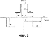
Для оптических волокон, профиль показателя преломления, в общем случае, задан в отношении разности значений между двумя точками на графике функции, связывающей показатель преломления с радиусом волокна. Традиционно, расстояние r до центра волокна откладывается по оси x профиля. Разность между показателем преломления на расстоянии r и показателем преломления внешней оболочки волокна откладывается по оси y (фиг. 2, позиции 21-24). Внешняя оболочка функционирует как оптическая оболочка и имеет, по существу, постоянный показатель преломления; эта оптическая оболочка, в общем случае, состоит из чистого кварца, но также может содержать одну или несколько легирующих примесей. Профиль показателя преломления оптического волокна называется "ступенчатым" профилем, "трапецеидальным" профилем или "треугольным" профилем для графиков, имеющих соответствующие формы ступеньки, трапеции или треугольника. Эти кривые, в общем случае, представляют теоретический или эталонный профиль показателя преломления (т.е. заданный профиль) волокна. Ограничения, связанные с производством волокна, могут приводить к немного другому профилю в фактическом волокне.For optical fibers, the refractive index profile is generally defined with respect to the difference between the two points on the graph of the function linking the refractive index with the radius of the fiber. Traditionally, the distance r to the center of the fiber is laid on the x axis of the profile. The difference between the refractive index at a distance r and the refractive index of the outer sheath of the fiber is plotted along the y axis (Fig. 2, positions 21-24). The outer shell functions as an optical shell and has a substantially constant refractive index; this optical cladding generally consists of pure quartz, but may also contain one or more dopants. The refractive index profile of an optical fiber is called a “stepped” profile, a “trapezoidal” profile, or a “triangular” profile for graphs that have the corresponding shape of a step, trapezoid, or triangle. These curves generally represent a theoretical or reference refractive index profile (i.e., a given profile) of a fiber. The limitations associated with fiber production can lead to a slightly different profile in the actual fiber.
Оптическое волокно традиционно состоит из (i) оптической сердцевины, имеющей функцию передачи и, в необязательном порядке, усиления оптического сигнала, и (ii) оптической оболочки, имеющей функцию ограничения оптического сигнала в сердцевине. С этой целью, показатели преломления сердцевины (nc) и оболочки (ng) должны удовлетворять условию nc>ng. Как известно в технике, распространение оптического сигнала в одномодовом оптическом волокне подразделяется на основную моду (известную как LP01), канализируемую в сердцевине, и вторичные моды, канализируемые в пределах определенного радиуса в комплексе сердцевина-оболочка.An optical fiber traditionally consists of (i) an optical core having a transmission function and, optionally, amplifying an optical signal, and (ii) an optical clad having a function of limiting an optical signal in a core. To this end, the refractive indices of the core (n c ) and shell (n g ) must satisfy the condition n c > n g . As is known in the art, the propagation of an optical signal in a single-mode optical fiber is subdivided into a main mode (known as LP01) channelized in the core and secondary modes channelized within a certain radius in the core-cladding complex.
Традиционно, ступенчатые волокна, также именуемые волокнами SMF ("одномодовыми волокнами") используются в качестве оптоволоконных линий для оптоволоконных систем связи. Эти волокна демонстрируют хроматическую дисперсию и наклон хроматической дисперсии, соответствующие конкретным стандартам телекоммуникаций.Conventionally, stepped fibers, also referred to as SMF fibers (“single-mode fibers”), are used as fiber optic lines for fiber optic communication systems. These fibers exhibit chromatic dispersion and the slope of chromatic dispersion corresponding to specific telecommunication standards.
Для обеспечения совместимости между оптическими системами от разных производителей, Международный союз электросвязи (ITU) установил стандарт для нормального волокна, именуемый ITU-T G.652, которому должно соответствовать стандартное одномодовое волокно (SSMF).To ensure interoperability between optical systems from different manufacturers, the International Telecommunication Union (ITU) has set a standard for normal fiber called ITU-T G.652, which must conform to standard single-mode fiber (SSMF).
Этот стандарт G.652 для волокон связи рекомендует, помимо прочего, номинальный диапазон от 8,6 микрон до 9,5 микрон для диаметра поля моды (MFD) на длине волны 1310 нанометров, который может варьироваться в пределах ±0,4 мкм вследствие производственных допусков; максимальную длину волны отсечки кабеля 1260 нанометров; диапазон от 1300 нанометров до 1324 нанометров для длины волны компенсации дисперсии (обозначаемой λ0); и максимальный наклон кривой хроматической дисперсии 0,092 пс/(нм2·км) (т.е. пс/нм2/км).This G.652 standard for bond fibers recommends, among other things, a nominal range from 8.6 microns to 9.5 microns for mode field diameter (MFD) at a wavelength of 1310 nanometers, which can vary within ± 0.4 microns due to manufacturing tolerances; maximum cable cut-off wavelength 1260 nanometers; a range from 1300 nanometers to 1324 nanometers for a dispersion compensation wavelength (denoted λ 0 ); and a maximum slope of the chromatic dispersion curve of 0.092 ps / (nm 2 · km) (i.e. ps / nm 2 / km).
Длина волны отсечки кабеля традиционно измеряется как длина волны, на которой оптический сигнал перестает быть одномодовым после распространения по 22 метрам волокна, например, установленная Подкомиссией 86A Международной электротехнической комиссии в стандарте IEC 60793-1-44.The cable cut-off wavelength is traditionally measured as the wavelength at which the optical signal ceases to be single-mode after propagating over 22 meters of fiber, for example, established by Subcommission 86A of the International Electrotechnical Commission in IEC 60793-1-44.
В большинстве случаев, вторичная мода, наиболее устойчивая к потерям на изгибе, является модой LP11. Таким образом, длина волны отсечки кабеля является длиной волны, за пределами которой мода LP11 испытывает значительное затухание после распространения по 22 метрам волокна. Способ, предложенный согласно стандарту, исходит из того, что оптический сигнал является одномодовым, когда затухание моды LP11 больше или равно 19,3 дБ.In most cases, the secondary mode most resistant to bending loss is the LP11 mode. Thus, the cable cut-off wavelength is the wavelength beyond which the LP11 mode experiences significant attenuation after propagating over 22 meters of fiber. The method proposed according to the standard assumes that the optical signal is single-mode when the attenuation of the LP11 mode is greater than or equal to 19.3 dB.
Кроме того, для данного волокна, так называемое значение MAC задается как отношение диаметра поля моды волокна на длине волны 1550 нанометров к эффективной длине волны отсечки λceff. Длина волны отсечки традиционно измеряется как длина волны, на которой оптический сигнал перестает быть одномодовым после распространения по двум метрам волокна, установленная Подкомиссией 86A Международной электротехнической комиссии в стандарте IEC 60793-1-44. MAC представляет собой параметр, позволяющий оценить характеристики волокна, в частности, для нахождения компромисса между диаметром поля моды, эффективной длиной волны отсечки и потерями на изгибе.In addition, for a given fiber, the so-called MAC value is specified as the ratio of the diameter of the mode field of the fiber at a wavelength of 1550 nanometers to the effective cutoff wavelength λ ceff . The cut-off wavelength is traditionally measured as the wavelength at which the optical signal ceases to be single-mode after propagating over two meters of fiber, established by Subcommission 86A of the International Electrotechnical Commission in IEC 60793-1-44. MAC is a parameter that allows you to evaluate the characteristics of the fiber, in particular, to find a compromise between the diameter of the mode field, the effective cut-off wavelength, and bending loss.
В Европейской патентной заявке № 1,845,399 и Европейской патентной заявке № 1,785,754, представлены экспериментальные результаты Заявителя. В этих более ранних заявках установлено соотношение между значением MAC на длине волны 1550 нанометров и потерями на изгибе на длине волны 1625 нанометров при радиусе кривизны 15 миллиметров в стандартном ступенчатом волокне SSMF. Каждая из этих Европейских патентных заявок, таким образом, включена сюда в полном объеме в порядке ссылки. Кроме того, в каждой заявке установлено, что значение MAC влияет на потери на изгибе волокна, и что снижение MAC приводит к снижению этих потерь на изгибе. Уменьшение диаметра поля моды и/или увеличение эффективной длины волны отсечки приводит к снижению значения MAC, но может приводить к несогласованности со стандартом G.652, из-за чего волокно становится коммерчески несовместимым с некоторыми системами связи.European Patent Application No. 1,845,399 and European Patent Application No. 1,785,754 present experimental results of the Applicant. In these earlier applications, a relationship is established between the MAC value at a wavelength of 1550 nanometers and the bending loss at a wavelength of 1625 nanometers with a radius of curvature of 15 millimeters in a standard stepped SSMF fiber. Each of these European patent applications is hereby incorporated by reference in its entirety. In addition, in each application it was found that the MAC value affects the loss in bending of the fiber, and that a decrease in MAC leads to a decrease in these loss in bending. A decrease in the mode field diameter and / or an increase in the effective cut-off wavelength leads to a decrease in the MAC value, but can lead to inconsistency with the G.652 standard, due to which the fiber becomes commercially incompatible with some communication systems.
Снижение потерь на изгибе, сохраняя определенные параметры оптической передачи, представляет проблему для применений волокон, предназначенных для оптоволоконных систем, ориентированных на пользователя, именуемых FTTH для проекта «Волокно до дома».Reducing bending loss while maintaining certain optical transmission parameters is a problem for fiber applications designed for user-oriented fiber systems, referred to as FTTH for the Fiber to Home project.
Международный союз электросвязи ITU также установил стандарты, именуемые ITU-T G.657A и ITU-T G.657B, которым должны удовлетворять оптические волокна, предназначенные для применений FTTH, в частности, в отношении устойчивости к потерям на изгибе. Стандарт G.657A налагает ограничения на значения потерь на изгибе, но нацелен, помимо прочего, на сохранение совместимости со стандартом G.652, в частности, в отношении диаметра поля моды MFD и хроматической дисперсии. С другой стороны, стандарт G.657B налагает строгие ограничения на потери на изгибе, в частности, (i) потери на изгибе меньше 0,003 дБ/виток на длине волны 1550 нанометров для радиуса кривизны 15 миллиметров и (ii) потери на изгибе меньше 0,01 дБ/виток на длине волны 1625 нанометров для радиуса кривизны 15 миллиметров.The ITU International Telecommunication Union has also set standards called ITU-T G.657A and ITU-T G.657B, which must be met by optical fibers intended for FTTH applications, in particular with regard to resistance to bending loss. The G.657A standard imposes restrictions on bending loss values, but is aimed, inter alia, at maintaining compatibility with the G.652 standard, in particular with respect to the field diameter of the MFD mode and chromatic dispersion. The G.657B standard, on the other hand, imposes strict limits on bending loss, in particular (i) bending loss of less than 0.003 dB / revolution at a wavelength of 1,550 nanometers for a radius of curvature of 15 millimeters and (ii) bending loss of less than 0, 01 dB / revolution at a wavelength of 1625 nanometers for a radius of curvature of 15 millimeters.
В Европейской патентной заявке № 1,845,399 и Европейской патентной заявке № 1,785,754 предложены профили волокна, имеющие ограниченные потери на изгибе, соответствующие, в частности, критериям стандартов G.657A и G.657B. Однако профили, описанные в этих европейских патентных заявках, позволяют достигать только ограничений на потери на изгибе, налагаемых стандартом G.657B.European Patent Application No. 1,845,399 and European Patent Application No. 1,785,754 provide fiber profiles having limited bending loss, meeting, in particular, the criteria of G.657A and G.657B. However, the profiles described in these European patent applications only allow the bending loss limits imposed by the G.657B standard to be achieved.
В патенте США № 7,164,835 и опубликованной патентной заявке США № 2007/0147756, которые, таким образом, включены сюда в полном объеме в порядке ссылки, также описаны профили волокна, демонстрирующие ограниченные потери на изгибе. Однако волокна, предложенные в этих патентах США, соответствуют только критериям стандартов G.657A и G.657B, в частности, в отношении диаметра поля моды и хроматической дисперсии.U.S. Patent No. 7,164,835 and U.S. Patent Application Publication No. 2007/0147756, which are hereby incorporated by reference in their entireties, also describe fiber profiles exhibiting limited bending loss. However, the fibers proposed in these US patents meet only the criteria of G.657A and G.657B standards, in particular with respect to mode field diameter and chromatic dispersion.
В настоящее время, для определенных применений, снижение потерь на изгибе играет существенную роль, особенно, когда волокно подлежит креплению скобками или свертыванию в бухты в миниатюрной оптической коробке.Currently, for certain applications, reducing bending loss plays a significant role, especially when the fiber needs to be braced or coiled into a miniature optical box.
Технология производства волокна с воздушными каналами позволяет достигать высоких характеристик в отношении потерь на изгибе, но эта технология сложна и дорога в реализации и не может использоваться для волокон, предназначенных для систем FTTH, которые являются экономичными системами.Fiber technology with air ducts allows to achieve high performance in terms of bending loss, but this technology is complicated and expensive to implement and cannot be used for fibers intended for FTTH systems, which are economical systems.
Заявитель продвигает на рынок волокно, нечувствительное к изгибу, имеющее высокую устойчивость к потерям на изгибе под торговой маркой BendBright-XS. Эта линейка волокон полностью согласуется с рекомендациями ITU-T G.652 и G.657B и представляет типичные потери на изгибе 0,3 дБ/виток при радиусе кривизны 5 мм на длине волны 1550 нм. Это обуславливает необходимость в оптическом волокне, имеющем типичную устойчивость к потерям на изгибе, которая значительно выше для радиуса кривизны 5 мм, чем типичный уровень для вышеупомянутого волокна, продвигаемого на рынке. Волокно, отвечающее этому критерию, также должно оставаться совместимым со стандартом G.652 в отношении профиля передачи и, в частности, диаметра поля моды и длины волны отсечки кабеля. Этого заметного снижения потерь на изгибе можно добиться в ущерб более высокой длины волны отсечки, при условии, что (i) мода LP11 непосредственно более высокого порядка испытывает существенное затухание, и (ii) длина волокна, необходимая для того, чтобы затухание моды LP11 достигало 19,3 дБ на длине волны 1260 нанометров, составляет меньше 22 метров, таким образом, гарантируя, что длина волны отсечки кабеля меньше или равна 1260 нм. Волокно, отвечающее этому критерию, также должно оставаться совместимым со стандартом G.657B.Applicant marketed bend-insensitive fiber with high resistance to bending loss under the brand name BendBright-XS. This line of fibers is fully consistent with ITU-T recommendations G.652 and G.657B and represents typical bending losses of 0.3 dB / turn with a radius of curvature of 5 mm at a wavelength of 1550 nm. This necessitates an optical fiber having a typical resistance to loss in bending, which is significantly higher for a radius of curvature of 5 mm than a typical level for the aforementioned fiber marketed. A fiber meeting this criterion should also remain compatible with the G.652 standard with respect to the transmission profile and, in particular, the mode field diameter and the cable cut-off wavelength. This noticeable reduction in bending loss can be achieved to the detriment of a higher cutoff wavelength, provided that (i) the directly higher order LP11 mode experiences significant attenuation, and (ii) the fiber length required for the LP11 mode to attenuate to 19 , 3 dB at a wavelength of 1260 nanometers, is less than 22 meters, thus ensuring that the cable cut-off wavelength is less than or equal to 1260 nm. A fiber that meets this criterion must also remain compatible with the G.657B standard.
Сущность изобретенияSUMMARY OF THE INVENTION
В вышеописанных целях, изобретение включает в себя волокно с центральной сердцевиной, промежуточной оболочкой и оболочкой с вдавленными канавками, окруженной внешней оптической оболочкой. Профиль показателя преломления оптимизирован для снижения потерь на изгибе в десять раз относительно ограничений, налагаемых стандартом G.657B, в то же время, сохраняя диаметр поля моды, совместимый со стандартом G.652, и гарантируя достаточное затухание моды LP11.For the above-described purposes, the invention includes a fiber with a central core, an intermediate sheath and a sheath with depressed grooves surrounded by an external optical sheath. The refractive index profile is optimized to reduce bending loss by a factor of ten relative to the restrictions imposed by the G.657B standard, while maintaining a mode field diameter compatible with the G.652 standard and ensuring sufficient attenuation of the LP11 mode.
В частности, поверхность сердцевины, а также поверхность и объем оболочки с вдавленными канавками, оптимизированы для значительного снижения потерь на изгибе. В контексте изобретения, поверхность сердцевины или поверхность оболочки с вдавленными канавками не должна расширяться геометрически, но должна соответствовать значениям с учетом двух измерений - произведению радиуса и разности показателей преломления. Аналогично, объем оболочки с вдавленными канавками соответствует значению с учетом трех измерений - произведению квадрата радиуса и разности показателей преломления.In particular, the surface of the core, as well as the surface and volume of the shell with indented grooves, are optimized to significantly reduce bending loss. In the context of the invention, the core surface or the shell surface with indented grooves should not expand geometrically, but should correspond to the values taking into account two dimensions - the product of the radius and the difference of the refractive indices. Similarly, the volume of the shell with indented grooves corresponds to the value taking into account three dimensions - the product of the square of the radius and the difference in refractive indices.
Изобретение предлагает, в частности, одномодовое оптическое волокно, включающее в себя, от центра к периферии, центральную сердцевину, промежуточную оболочку, оболочку с вдавленными канавками и внешнюю оптическую оболочку. Центральная сердцевина имеет радиус r1 и положительную разность показателей преломления Δn1 с внешней оптической оболочкой. Промежуточная оболочка имеет радиус r2 и положительную разность показателей преломления Δn2 с внешней оптической оболочкой. Разность Δn2 меньше разности показателей преломления Δn1 сердцевины. Оболочка с вдавленными канавками имеет радиус r3 и отрицательную разность показателей преломления Δn3 с внешней оптической оболочкой. Волокно, отвечающее этому изобретению, также отличается тем, что (i) его номинальный диаметр поля моды (MFD) составляет от 8,6 мкм до 9,5 мкм на длине волны 1310 нанометров и (ii) его потери на изгибе меньше 0,15 дБ/виток для радиуса кривизны 5 миллиметров на длине волны 1550 нанометров, и длина волны отсечки кабеля меньше или равна 1260 нм, причем она измеряется как длина волны, на которой затухание моды LP11 больше или равно 19,3 дБ после распространения по двадцати двум метрам волокна, причем волокно находится либо в прямом состоянии, либо намотано на бобину с радиусом кривизны 140 мм.The invention provides, in particular, a single-mode optical fiber including, from a center to a periphery, a central core, an intermediate shell, a cavity with indented grooves, and an external optical shell. The central core has a radius r 1 and a positive difference in refractive indices Δn 1 with the external optical cladding. The intermediate shell has a radius r 2 and a positive difference in refractive indices Δn 2 with the external optical shell. The difference Δn 2 is less than the difference in the refractive indices Δn 1 of the core. A shell with indented grooves has a radius r 3 and a negative difference in refractive indices Δn 3 with an external optical shell. The fiber of this invention is also characterized in that (i) its nominal mode field diameter (MFD) is from 8.6 μm to 9.5 μm at a wavelength of 1310 nanometers and (ii) its bending loss is less than 0.15 dB / turn for a radius of curvature of 5 millimeters at a wavelength of 1,550 nanometers, and a cable cut-off wavelength of less than or equal to 1260 nm, and it is measured as the wavelength at which the LP11 mode attenuation is greater than or equal to 19.3 dB after propagation over twenty-two meters fiber, and the fiber is either upright or wound on a reel with p radius of curvature of 140 mm.
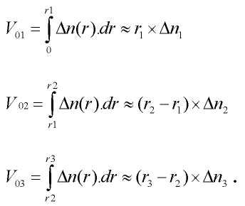
Согласно одному варианту осуществления волокна, отвечающего этому изобретению, поверхностный интеграл по центральной сердцевине (V01), заданный какAccording to one embodiment of the fiber of this invention, the central core surface integral (V 01 ), defined as
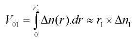
составляет от 19,0×10⁻³ мкм до 23,0×10⁻³ мкм и, предпочтительно, от 20,0×10⁻³ мкм до 23,0×10⁻³ мкм. В еще одном предпочтительном варианте осуществления поверхностный интеграл по центральной сердцевине (V01) составляет от 20,0×10⁻³ мкм до 21,5×10⁻³ мкм, поскольку это обеспечивает оптимизацию оптических свойств настоящего волокна.ranges from 19.0 × 10 −3 μm to 23.0 × 10 −3 μm and, preferably, from 20.0 × 10 −3 μm to 23.0 × 10 −3 μm. In yet another preferred embodiment, the surface integral over the central core (V 01 ) is from 20.0 × 10 −3 μm to 21.5 × 10 −3 μm, as this enables optimization of the optical properties of the present fiber.
Согласно одному варианту осуществления волокна, отвечающего этому изобретению, поверхностный интеграл по оболочке с вдавленными канавками (V03), заданный какAccording to one embodiment of the fiber of this invention, the sheath surface integral with indented grooves (V 03 ), defined as
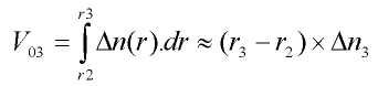
составляет от -55,0×10⁻³ мкм до -30,0×10⁻³ мкм. В еще одном предпочтительном варианте осуществления поверхностный интеграл по оболочке с вдавленными канавками (V03) составляет от -42,5×10⁻³ мкм до -32,5×10⁻³ мкм, поскольку это обеспечивает оптимизацию оптических свойств настоящего волокна.ranges from -55.0 × 10 -3 μm to -30.0 × 10 -3 μm. In yet another preferred embodiment, the surface integral over the sheath with the indented grooves (V 03 ) is from -42.5 × 10 -3 μm to -32.5 × 10 -3 μm, as this provides optimization of the optical properties of the present fiber.
Согласно одному варианту осуществления волокна, отвечающего этому изобретению, объемный интеграл по оболочке с вдавленными канавками (V13), заданный какAccording to one embodiment of the fiber of this invention, the bulk integral over the sheath with indented grooves (V 13 ), defined as
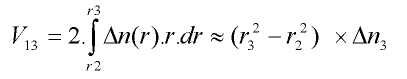
составляет от -1200×10-3 мкм2 до -750×10-3 мкм2. В еще одном предпочтительном варианте осуществления объемный интеграл по оболочке с вдавленными канавками (V13) составляет от -1000×10-3 мкм2 до -750×10-3 мкм2, поскольку это обеспечивает оптимизацию оптических свойств настоящего волокна.ranges from -1200 × 10 -3 μm 2 to -750 × 10 -3 μm 2 . In yet another preferred embodiment, the bulk integral over the sheath with the indented grooves (V 13 ) is from −1000 × 10 −3 μm 2 to −750 × 10 −3 μm 2 , since this provides optimization of the optical properties of the present fiber.
В предпочтительных вариантах осуществления, волокно имеет физические свойства и эксплуатационные параметры с повышенной устойчивостью к потерям на изгибе. Например, волокно имеет эффективную длину волны отсечки λceff больше 1300 нанометров, причем эффективная длина волны отсечки измеряется как длина волны, на которой оптический сигнал становится одномодовым после распространения по двум метрам волокна. Волокно имеет, для длины волны 1550 нанометров, потери на изгибе меньшие или равные 0,003 дБ/виток для радиуса кривизны 15 миллиметров, потери на изгибе меньшие или равные 3×10⁻² дБ/виток, предпочтительно, 7,5×10⁻³ дБ/виток для радиуса кривизны 10 миллиметров, потери на изгибе меньшие или равные 0,05 дБ/виток для радиуса кривизны 7,5 миллиметров, и потери на изгибе меньше 0,15 дБ/виток, предпочтительно, меньше 0,10 дБ/виток для радиуса кривизны 5 миллиметров.In preferred embodiments, the fiber has physical properties and performance with increased resistance to bending loss. For example, a fiber has an effective cut-off wavelength λ ceff of more than 1300 nanometers, the effective cut-off wavelength being measured as the wavelength at which the optical signal becomes single-mode after propagating over two meters of fiber. The fiber has, for a wavelength of 1,550 nanometers, bending losses less than or equal to 0.003 dB / turn for a radius of curvature of 15 millimeters, bending losses less than or equal to 3 × 10 -2 dB / turn, preferably 7.5 × 10 -3 dB / turn for a radius of curvature of 10 millimeters, bending loss less than or equal to 0.05 dB / turn for a radius of curvature of 7.5 mm, and loss in bending less than 0.15 dB / turn, preferably less than 0.10 dB / turn for radius of curvature of 5 millimeters.
Раскрытое здесь волокно также демонстрирует снижение потерь на изгибе на более высоких длинах волны. Например, на длине волны 1625 нанометров, волокно имеет потери на изгибе меньше 10-2 дБ/виток, предпочтительно, меньше 1,5 × 10⁻³ дБ/виток для радиуса кривизны 15 миллиметров, потери на изгибе меньшие или равные 0,1 дБ/виток, предпочтительно, меньшие или равные 25×10-3 дБ/виток для радиуса кривизны 10 миллиметров, потери на изгибе меньшие или равные 0,15 дБ/виток, предпочтительно, меньшие или равные 0.08 дБ/виток для радиуса кривизны 7.5 миллиметров, и потери на изгибе меньшие или равные 0,25 дБ/виток для радиуса кривизны 5 миллиметров. Соответственно, в предпочтительном варианте осуществления, волокно имеет длину волны отсечки от 1240 нанометров до 1310 нанометров, причем длина волны отсечки измеряется как длина волны, на которой оптический сигнал перестает быть одномодовым после распространения по пяти метрам волокна. Длина волны отсечки отличается от длины волны отсечки кабеля, измеряемой как длина волны, на которой затухание моды LP11 больше или равно 19,3 дБ после распространения по 22 метрам волокна. Волокно имеет длину волны отсечки кабеля меньшую или равную 1260 нанометрам.The fiber disclosed herein also exhibits a reduction in bending loss at higher wavelengths. For example, at a wavelength of 1625 nanometers, the fiber has a bend loss of less than 10 -2 dB / turn, preferably less than 1.5 × 10 -3 dB / turn for a radius of curvature of 15 millimeters, bend loss less than or equal to 0.1 dB / turn, preferably less than or equal to 25 × 10 -3 dB / turn for a radius of curvature of 10 millimeters, bending loss less than or equal to 0.15 dB / turn, preferably less than or equal to 0.08 dB / turn for a radius of curvature of 7.5 millimeters, and bending losses of less than or equal to 0.25 dB / turn for a radius of curvature of 5 millimeters. Accordingly, in a preferred embodiment, the fiber has a cut-off wavelength from 1240 nanometers to 1310 nanometers, the cut-off wavelength being measured as the wavelength at which the optical signal ceases to be single-mode after propagation over five meters of fiber. The cut-off wavelength is different from the cable cut-off wavelength, measured as the wavelength at which the attenuation of the LP11 mode is greater than or equal to 19.3 dB after propagating over 22 meters of fiber. The fiber has a cable cut-off wavelength of less than or equal to 1260 nanometers.
Четвертое определение длины волны отсечки, рассматриваемое здесь, представляет собой теоретическую длину волны отсечки, заданную как длину волны, за пределами которой мода LP11 распространяется в режиме утечки. В одном варианте осуществления, волокно имеет теоретическую длину волны отсечки меньшую или равную 1250 нанометрам. Волокно имеет затухание моды LP11 больше 5 дБ после распространения по 22 метрам волокна на длине волны 1260 нанометров.The fourth definition of the cutoff wavelength considered here is a theoretical cutoff wavelength defined as the wavelength beyond which the LP11 mode propagates in leakage mode. In one embodiment, the fiber has a theoretical cutoff wavelength of less than or equal to 1250 nanometers. The fiber has an LP11 mode attenuation of more than 5 dB after propagating over 22 meters of fiber at a wavelength of 1260 nanometers.
Вышеописанные эксплуатационные параметры вытекают из предпочтительных физических свойств волокна. В одном варианте осуществления, центральная сердцевина волокна имеет радиус от 3,8 мкм до 4,35 мкм; промежуточная оболочка имеет радиус от 8,5 мкм до 9,7 мкм; оболочка с вдавленными канавками имеет радиус от 13,5 мкм до 16 мкм, который может быть меньше или равен 15 мкм. Центральная сердцевина, предпочтительно, имеет разность показателей преломления (Δn1) с внешней оптической оболочкой от 4,9×10⁻³ до 5,7×10⁻³.The above operational parameters result from the preferred physical properties of the fiber. In one embodiment, the central core of the fiber has a radius of 3.8 μm to 4.35 μm; the intermediate shell has a radius of 8.5 μm to 9.7 μm; the shell with indented grooves has a radius of 13.5 μm to 16 μm, which may be less than or equal to 15 μm. The central core preferably has a refractive index difference (Δn 1 ) with the outer optical cladding of 4.9 × 10 -3 to 5.7 × 10 -3 .
Как отмечено выше, профиль показателя преломления волокна графически представлен в отношении разности между значениями показателя преломления в точках на радиусе волокна и внешней оптической оболочки. Промежуточная оболочка имеет разность показателей преломления с оптической оболочкой от -0,1×10⁻³ до 0,6×10⁻³. Оболочка с вдавленными канавками имеет разность показателей преломления с оптической оболочкой от -10,0×10⁻³ до -5,0×10⁻³. Волокно имеет длину волны нулевой хроматической дисперсии от 1300 нанометров до 1324 нанометров; волокно имеет значение коэффициента хроматической дисперсии на длине волны нулевой хроматической дисперсии меньше 0,092 пс/(нм2·км).As noted above, the profile of the refractive index of the fiber is graphically presented in relation to the difference between the values of the refractive index at points on the radius of the fiber and the outer optical shell. The intermediate shell has a difference in refractive index with the optical shell of from -0.1 × 10 -3 to 0.6 × 10 -3 . The shell with indented grooves has a difference in refractive index with the optical shell of from -10.0 × 10 -3 to -5.0 × 10 -3 . The fiber has a wavelength of zero chromatic dispersion from 1300 nanometers to 1324 nanometers; the fiber has a value of the coefficient of chromatic dispersion at a wavelength of zero chromatic dispersion less than 0,092 ps / (nm 2 · km).
Изобретение также относится к оптической коробке, принимающей, по меньшей мере, один участок раскрытого здесь волокна. В такой коробке, волокно может располагаться с радиусом кривизны меньше 15 миллиметров, который может составлять порядка 5 миллиметров. Изобретение также относится к оптоволоконной системе, подведенной к дому абонента (FTTH), содержащей, по меньшей мере, один участок оптического волокна, отвечающего изобретению.The invention also relates to an optical box receiving at least one portion of a fiber disclosed herein. In such a box, the fiber can be arranged with a radius of curvature of less than 15 millimeters, which can be on the order of 5 millimeters. The invention also relates to a fiber optic system brought to a subscriber’s house (FTTH) comprising at least one portion of an optical fiber according to the invention.
Вышеизложенные, а также другие характеристики и преимущества настоящего изобретения и порядок их реализации дополнительно раскрыты в нижеследующем подробном описании и прилагаемых чертежах.The above, as well as other characteristics and advantages of the present invention and the procedure for their implementation are further disclosed in the following detailed description and the accompanying drawings.
Краткое описание чертежейBrief Description of the Drawings
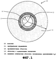
Фиг. 1 - вид в разрезе одномодового оптического волокна со слоями оболочки, отстоящими от центра на соответствующие радиусы.FIG. 1 is a sectional view of a single-mode optical fiber with sheath layers spaced apart from the center by respective radii.
Фиг. 2 - номинальный профиль показателя преломления иллюстративного одномодового оптического волокна, показанного на фиг. 1 согласно настоящему изобретению.FIG. 2 is a nominal refractive index profile of the illustrative single-mode optical fiber shown in FIG. 1 according to the present invention.
Подробное описаниеDetailed description
Волокно (10), отвечающее изобретению, имеет центральную сердцевину (11), промежуточную оболочку (12) и оболочку (13) с вдавленными канавками. В целях настоящей заявки и без ограничения объема изобретения, оболочка с вдавленными канавками представляет собой радиальный участок волокна (10), показатель преломления которого меньше показателя преломления внешней оптической оболочки (14). Обычно центральная сердцевина (11), промежуточная оболочка (12) и оболочка (13) с вдавленными канавками формируются путем химического осаждения из паровой фазы в кварцевой трубке. Внешняя оптическая оболочка (14) включает в себя кварцевую трубку и внешнюю оболочку на трубке. В предпочтительных вариантах осуществления, внешняя оболочка, в общем случае, выполнена из природного или легированного кварца, но также может быть получена любым другим методом осаждения ((аксиального осаждения из паровой фазы ("VAD") или внешнего осаждения из паровой фазы ("OVD")).The fiber (10) according to the invention has a central core (11), an intermediate sheath (12) and a sheath (13) with indented grooves. For the purposes of the present application and without limiting the scope of the invention, the sheath with indented grooves is a radial portion of the fiber (10), the refractive index of which is less than the refractive index of the outer optical shell (14). Typically, a central core (11), an intermediate shell (12), and a shell (13) with indented grooves are formed by chemical vapor deposition in a quartz tube. The outer optical shell (14) includes a quartz tube and an outer shell on the tube. In preferred embodiments, the outer shell is generally made of natural or doped quartz, but can also be obtained by any other deposition method ((axial vapor deposition ("VAD") or external vapor deposition ("OVD" )).
На фиг. 2 показан профиль показателя преломления для волокна передачи (10), показанного на фиг. 1. Профиль, представленный на фиг. 2, является заданным профилем, т.е. представляет теоретический профиль волокна, но волокно, в действительности полученное после вытягивания волокна из заготовки, может иметь немного другой профиль.In FIG. 2 shows a refractive index profile for the transmission fiber (10) shown in FIG. 1. The profile shown in FIG. 2 is a predetermined profile, i.e. represents the theoretical fiber profile, but the fiber actually obtained after drawing the fiber from the preform may have a slightly different profile.
Оптическое волокно (10) получают известным способом путем вытягивания заготовки. В порядке примера, заготовка может представлять собой трубку из стекла очень высокого качества (чистого кварца), из которой, в конце концов, образуется часть внешней оптической оболочки (14). Внешняя оптическая оболочка (14) окружает центральную сердцевину (11) и внутренние оболочки (12, 13) волокна (10). Затем эту трубку покрывают внешним покрытием для увеличения ее диаметра прежде, чем перейти к операции вытягивания волокна в колонне вытягивания волокна. Для создания заготовки, трубку, в общем случае, устанавливают горизонтально и удерживают на обоих концах стеклянными полосками на токарном станке; затем трубку вращают и подвергают локальному нагреву для процесса осаждения, определяющего состав заготовки. Этот состав определяет оптические характеристики будущего волокна.The optical fiber (10) is obtained in a known manner by stretching the preform. As an example, the preform can be a tube of very high quality glass (pure quartz), from which, ultimately, a part of the external optical shell is formed (14). The outer optical cladding (14) surrounds the central core (11) and the inner cladding (12, 13) of the fiber (10). This tube is then coated with an outer coating to increase its diameter before proceeding to the fiber drawing operation in the fiber drawing column. To create a workpiece, the tube is generally mounted horizontally and held at both ends by glass stripes on a lathe; then the tube is rotated and subjected to local heating for the deposition process, which determines the composition of the workpiece. This composition determines the optical characteristics of the future fiber.
Волокно включает в себя центральную сердцевину (11), имеющую разность показателей преломления Δn1 с внешней оболочкой (14), функционирующей как оптическая оболочка. Волокно (10) дополнительно включает в себя промежуточную оболочку (12), имеющую разность показателей преломления Δn2 с внешней оптической оболочкой (14) и оболочку (13) с вдавленными канавками, имеющую разность показателей преломления Δn3 с внешней оптической оболочкой (14). Показатели преломления в центральной сердцевине (11), промежуточной оболочке (12) и оболочке (13) с вдавленными канавками, по существу, постоянны на протяжении их соответствующей ширины, как указано на фиг. 2. На фиг. 1 показано, что ширина сердцевины (11) определяется ее радиусом r1, и ширина оболочек определяется их соответствующими внешними радиусами, r2 и r3. Внешняя оптическая оболочка обозначена как r4.The fiber includes a central core (11) having a difference in refractive indices Δn 1 with the outer shell (14), which functions as an optical shell. Fiber (10) further includes an intermediate cladding (12) having a difference in refractive index Δn 2 with an external optical cladding (14) and a clad (13) with indented grooves having a difference in refractive index Δn 3 with an external optical cladding (14). The refractive indices in the central core (11), the intermediate shell (12) and the shell (13) with indented grooves are substantially constant over their respective widths, as indicated in FIG. 2. In FIG. 1 shows that the width of the core (11) is determined by its radius r 1 , and the width of the shells is determined by their respective external radii, r 2 and r 3 . The outer optical cladding is designated as r 4 .
Для задания заданного профиля показателя преломления для оптического волокна, значение показателя преломления внешней оптической оболочки, в общем случае, считается опорным значением (ng). Значения показателя преломления центральной сердцевины (11), промежуточной оболочки (12) и оболочки (13) с вдавленными канавками затем выражаются на фиг. 2 как разности показателей преломления Δn1,2,3. В общем случае, внешняя оптическая оболочка (14) состоит из кварца, но эту оболочку можно легировать для увеличения или уменьшения ее показателя преломления - например, для изменения характеристик распространения сигнала.To set a given refractive index profile for an optical fiber, the refractive index value of the outer optical cladding is generally considered to be a reference value (n g ). The refractive index values of the central core (11), the intermediate shell (12) and the shell (13) with indented grooves are then expressed in FIG. 2 as the difference in refractive indices Δn 1,2,3 . In the general case, the outer optical shell (14) consists of quartz, but this shell can be doped to increase or decrease its refractive index - for example, to change the propagation characteristics of a signal.
Каждую секцию профиля волокна, показанного на фиг. 2 (21-24) также можно задать на основании интегралов, которые связывают изменения показателя преломления с радиусом каждой секции волокна (10). Таким образом, можно задать три поверхностных интеграла для волокна (10), отвечающего изобретению, представляющие поверхность сердцевины V01, поверхность промежуточной оболочки V02 и поверхность оболочки с вдавленными канавками V03. Выражение "поверхностный" не следует понимать в геометрическом смысле, но оно соответствует значению с учетом двух измерений. Эти три поверхностных интеграла можно выразить следующим образом:Each section of the fiber profile shown in FIG. 2 (21-24) can also be set based on integrals that relate the changes in the refractive index to the radius of each fiber section (10). Thus, three surface integrals can be defined for the fiber (10) according to the invention, representing the core surface V 01 , the surface of the intermediate shell V 02 and the surface of the sheath with indented grooves V 03 . The expression “superficial” should not be understood in a geometric sense, but it corresponds to a value with two dimensions taken into account. These three surface integrals can be expressed as follows:
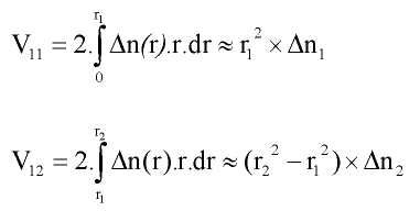
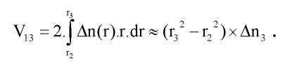
Аналогично, можно задать три объемных интеграла для волокна (10), отвечающего изобретению, представляющие объем сердцевины V11, объем промежуточной оболочки V12 и объем оболочки с вдавленными канавками V13. Выражение "объемный" не следует понимать в геометрическом смысле, но оно соответствует значению с учетом трех измерений. Эти три объемных интеграла можно выразить следующим образом:Similarly, three volume integrals can be defined for the fiber (10) according to the invention, representing the core volume V 11 , the volume of the intermediate sheath V 12 and the sheath volume with the grooves V 13 indented. The expression "volumetric" should not be understood in a geometric sense, but it corresponds to a value taking into account three dimensions. These three volume integrals can be expressed as follows:
В Таблице I (см. ниже) показано 9 примеров профилей волокна согласно предпочтительным вариантам осуществления изобретения по сравнению с тремя профилями волокна SSMF и одним профилем волокна, соответствующим стандартам G.657A и G.657B (обозначенным как "BIF" для волокна, нечувствительного к изгибу) а также 13 сравнительных примеров. Заявитель продвигает на рынок волокно, нечувствительное к изгибу, имеющее высокую устойчивость к потерям на изгибе под торговой маркой BendBright. Значения в таблицах соответствуют заданным профилям для каждого волокна.Table I (see below) shows 9 examples of fiber profiles according to preferred embodiments of the invention compared to three SSMF fiber profiles and one fiber profile meeting G.657A and G.657B standards (designated as “BIF” for fiber insensitive to bending) as well as 13 comparative examples. Applicant marketed bend-insensitive fiber with high resistance to bend loss under the brand name BendBright. The values in the tables correspond to the specified profiles for each fiber.
Все профили также можно приспособить для обеспечения уровня многолучевых помех (MPI) ниже -30 дБ, что гарантирует полную совместимость с любыми надлежащим образом установленными сетями, в том числе Сетью доступа и Волокно к дому. MPI определена в работе W. Zheng и др., "Measurement and System Impact of Multipath Interference From Dispersion Compensating Fiber Modules", IEEE Transactions on Instrumentation and Measurement, 2004, 53, стр. 15-23) и в ее конкретных рассмотрениях измерений, детализированных в работе S. Ramachandran и др., "Measurement of Multipath Interference in the Coherent Crosstalk Regime", IEEE Photonics Technology Letters, 2003, 15, стр. 1171-1173.All profiles can also be adapted to provide a multipath interference level (MPI) below -30 dB, which ensures full compatibility with any properly installed networks, including Access Network and Fiber to the house. MPI is defined by W. Zheng et al., "Measurement and System Impact of Multipath Interference From Dispersion Compensating Fiber Modules", IEEE Transactions on Instrumentation and Measurement, 2004, 53, p. 15-23) and its specific considerations on measurements, detailed in S. Ramachandran et al., "Measurement of Multipath Interference in the Coherent Crosstalk Regime", IEEE Photonics Technology Letters, 2003, 15, pp. 1171-1173.
В первом столбце Таблицы I указаны обозначения всех примеров (Ex для примера согласно изобретению и C.Ex для сравнительных примеров); в следующих трех столбцах приведены значения радиусов сердцевины (11), промежуточной оболочки (12), и оболочки (13) с вдавленными канавками, соответственно. В следующих трех столбцах приведены соответствующие значения разностей показателей преломления с внешней оптической оболочкой (14). Значения показателя преломления измеряются на длине волны 633 нанометров. В Таблице I также показаны значения заданных выше поверхностного интеграла и объемного интеграла сердцевины (11), промежуточной оболочки (12) и оболочки (13) с вдавленными канавками.The first column of Table I indicates the designations of all examples (Ex for the example according to the invention and C.Ex for the comparative examples); the next three columns show the radii of the core (11), the intermediate shell (12), and the shell (13) with indented grooves, respectively. The next three columns show the corresponding values of the differences in refractive indices with the external optical shell (14). The refractive index values are measured at a wavelength of 633 nanometers. Table I also shows the values given above for the surface integral and volume integral of the core (11), the intermediate shell (12) and the shell (13) with indented grooves.
[10-3](microns)
[10 -3 ]
[10-3](microns)
[10 -3 ]
[10-3](microns)
[10 -3 ]
[10-3](μm 2 )
[10 -3 ]
[10-3](μm 2 )
[10 -3 ]
[10-3](μm 2 )
[10 -3 ]
Волокно (10) согласно варианту осуществления, представленному на фиг. 1 и 2, отвечающее изобретению, представляет собой ступенчатое волокно, содержащее центральную сердцевину (11), промежуточную оболочку (12) и оболочку (13) с вдавленными канавками. Из Таблицы I следует, что центральная сердцевина (11) имеет радиус r1 от 3,8 мкм до 4,35 мкм и, предпочтительно, от 3,8 мкм до 4,05 мкм, т.е. она уже, чем сердцевина волокна SSMF. Волокно (10) имеет разность показателей преломления Δn1 (21) с внешней оптической оболочкой (14) от 4,9×10⁻³ до 5,7×10⁻³, т.е. порядка или больше, чем волокно SSMF. Поверхностный интеграл сердцевины V01 составляет от 19,0×10⁻³ мкм до 23,0×10⁻³ мкм, и объемный интеграл сердцевины V11 составляет от 75×10-3 мкм2 до 91×10-3 мкм2.Fiber (10) according to the embodiment of FIG. 1 and 2, corresponding to the invention, is a stepped fiber containing a Central core (11), an intermediate shell (12) and a shell (13) with indented grooves. From Table I it follows that the central core (11) has a radius r 1 from 3.8 μm to 4.35 μm and, preferably, from 3.8 μm to 4.05 μm, i.e. it is narrower than the core of the SSMF fiber. Fiber (10) has a refractive index difference Δn 1 (21) with an external optical cladding (14) from 4.9 × 10 -3 to 5.7 × 10 -3 , i.e. order or more than SSMF fiber. The surface integral of the core V 01 is from 19.0 × 10 -3 μm to 23.0 × 10 -3 μm, and the volume integral of the core V 11 is from 75 × 10 -3 μm 2 to 91 × 10 -3 μm 2 .
Из Таблицы I также следует, что волокно, отвечающее изобретению, имеет оболочку (13) с вдавленными канавками. Оболочка (13) с вдавленными канавками имеет большой объем и позволяет значительно ограничивать потери на изгибе. Таблица I, таким образом, показывает, что оболочка с (13) вдавленными канавками имеет радиус r3 от 13,5 мкм и 16 мкм и разность показателей преломления Δn3 (23) с внешней оптической оболочкой (14) от -10,0×10⁻³ до -5,0×10⁻³. Таблица I также показывает, что поверхностный интеграл оболочки с вдавленными канавками V03, заданный выше, составляет от -55,0×10⁻³ мкм до -30,0×10⁻³ мкм, и объемный интеграл оболочки с вдавленными канавками V13, заданный выше, составляет от -1200×10-3 мкм2 до -750×10-3 мкм2.From Table I it also follows that the fiber of the invention has a sheath (13) with indented grooves. The shell (13) with indented grooves has a large volume and can significantly limit bending loss. Table I, thus, shows that the shell with (13) depressed grooves has a radius r 3 of 13.5 μm and 16 μm and a difference in refractive indices Δn 3 (23) with an external optical shell (14) of -10.0 × 10 −3 to −5.0 × 10 −3 . Table I also shows that the surface integral of the shell with indented grooves V 03 defined above is from -55.0 × 10 -3 μm to -30.0 × 10 -3 μm, and the volume integral of the shell with indented grooves V 13 , defined above, is from -1200 × 10 -3 μm 2 to -750 × 10 -3 μm 2 .
Согласно предпочтительному варианту осуществления, радиус оболочки с вдавленными канавками r3 можно ограничить до 15 мкм, чтобы дополнительно сократить стоимость производства волокна, и все волокна, отвечающие Примерам, согласуются с этим. Фактически, оболочку (13) с вдавленными канавками можно создавать посредством усиленного плазмой химического осаждения из паровой фазы (PCVD), что позволяет включать большое количество фтора в кварц для формирования оболочек с глубоко вдавленными канавками. Однако часть волокна (10), соответствующая трубке и осаждению PCVD является наиболее дорогостоящей; поэтому желательно как можно сильнее ограничить эту часть. Можно также предусмотреть создание оболочки (13) с вдавленными канавками путем включения микроканалов или микропузырьков вместо легирования фтором. Однако в условиях промышленного производства легче управлять легированием фтором, чем включением микропузырьков.According to a preferred embodiment, the radius of the sheath with the recessed grooves r 3 can be limited to 15 μm in order to further reduce the cost of fiber production, and all fibers corresponding to the Examples are consistent with this. In fact, shell (13) with indented grooves can be created by plasma enhanced chemical vapor deposition (PCVD), which allows large amounts of fluorine to be included in quartz to form shells with deep indented grooves. However, the portion of fiber (10) corresponding to the tube and PCVD deposition is the most expensive; therefore, it is desirable to limit this part as much as possible. It can also be envisaged to create a shell (13) with depressed grooves by including microchannels or microbubbles instead of doping with fluorine. However, in industrial production it is easier to control fluorine doping than to turn on microbubbles.
Оболочка (13) с вдавленными канавками, отвечающая заданным выше поверхностному и объемному критериям, позволяет достичь хорошего компромисса между значительным снижением потерь на изгибе по сравнению с существующими волокнами и достаточно согласованным режимом утечки моды LP11 на длине волны 1260 нанометров.The shell (13) with indented grooves that meets the above surface and volume criteria allows a good compromise between a significant reduction in bending losses compared to existing fibers and a fairly consistent mode of leakage of the LP11 mode at a wavelength of 1260 nanometers.
Из Таблицы I также следует, что предпочтительный вариант осуществления волокна имеет промежуточную оболочку (12) между центральной сердцевиной (11) и оболочкой (13) с вдавленными канавками. Эта промежуточная оболочка (12) позволяет ограничивать влияние оболочки с вдавленными канавками (13) на распространение оптического сигнала в сердцевине. Таблица I показывает, что промежуточная оболочка (12) имеет радиус r2 от 8,5 мкм до 9,7 мкм и разность показателей преломления Δn2 (22) с оптической оболочкой от -0,1×10⁻³ до 0,6×10⁻³. Таблица I показывает, что поверхностный интеграл промежуточной оболочки V02, заданный выше, составляет от -0,5×10⁻³ мкм до 3,0×10⁻³ мкм. Объемный интеграл промежуточной оболочки V12, заданный выше, составляет от -6×10⁻³ мкм2 до 40×10-3 мкм2.From Table I, it also follows that the preferred embodiment of the fiber has an intermediate sheath (12) between the central core (11) and the sheath (13) with indented grooves. This intermediate cladding (12) makes it possible to limit the influence of the cladding with depressed grooves (13) on the propagation of the optical signal in the core. Table I shows that the intermediate shell (12) has a radius r 2 from 8.5 μm to 9.7 μm and the difference in refractive indices Δn 2 (22) with an optical shell from -0.1 × 10 -3 to 0.6 × 10 -3 . Table I shows that the surface integral of the intermediate shell V 02 defined above is from −0.5 × 10 −3 μm to 3.0 × 10 −3 μm. The volume integral of the intermediate shell V 12 defined above is from -6 × 10 -3 μm 2 to 40 × 10 -3 μm 2 .
Центральная сердцевина (11) волокна (10), отвечающего изобретению, оптимизирована, совместно с промежуточной оболочкой (12), для обеспечения параметров оптической передачи в волокне в соответствии со стандартами G.652 и G657A, в частности, в отношении диаметра поля моды и хроматической дисперсии. Это также помогает гарантировать совместимость с волокнами других оптических систем.The central core (11) of the fiber (10) of the invention is optimized, together with the intermediate sheath (12), to provide optical transmission parameters in the fiber in accordance with G.652 and G657A, in particular with regard to mode field diameter and chromatic variance. It also helps ensure compatibility with the fibers of other optical systems.
В Таблице II (см. ниже) приведены характеристики оптической передачи для волокон, отвечающих изобретению. В первом столбце повторяются обозначения, указанные в Таблице I. Следующие столбцы обеспечивают, для каждого профиля волокна, значения диаметра поля моды (MFD) для длины волны 1310 нанометров и 1550 нанометров, длины волны нулевой дисперсии (ZDW) и наклона нулевой дисперсии (ZDS).Table II (see below) shows the optical transmission characteristics for the fibers of the invention. The designations shown in Table I are repeated in the first column. The following columns provide, for each fiber profile, mode field diameter (MFD) values for a wavelength of 1310 nanometers and 1550 nanometers, a zero dispersion wavelength (ZDW) and zero dispersion tilt (ZDS) .
(мкм)MFD1310
(microns)
(мкм)MFD1550
(microns)
(нм)Zdw
(nm)
пс/(нм2·км)Zds
ps / (nm 2 km)
Из Таблицы II следует, что волокно (10), отвечающее изобретению, совместимо с волокнами, соответствующими критериям стандарта G.652. В частности, раскрытое здесь волокно имеет диаметр поля моды MFD в стандартном диапазоне значений от 8,6 мкм до 9,5 мкм на длине волны 1310 нанометров, длину волны нулевой дисперсии от 1300 нанометров до 1324 нанометров, и наклон нулевой дисперсии меньше 0,092 пс/(нм2·км). Каждое из этих значений согласуется со стандартом G.652.From Table II it follows that the fiber (10) corresponding to the invention is compatible with fibers that meet the criteria of the G.652 standard. In particular, the fiber disclosed herein has an MFD mode field diameter in the standard range of 8.6 μm to 9.5 μm at a wavelength of 1310 nanometers, a zero dispersion wavelength of 1300 nanometers to 1324 nanometers, and a zero dispersion slope of less than 0.092 ps / (nm 2 · km). Each of these values complies with the G.652 standard.
С другой стороны, согласно Таблице III (см. ниже), волокно имеет эффективную длину волны отсечки λceff (или длину волны отсечки стандартного волокна, третий столбец Таблицы III) больше 1300 нанометров или даже больше 1350 нанометров. Как рассмотрено выше, эффективная длина волны отсечки измеряется как длина волны, на которой оптический сигнал перестает быть одномодовым после распространения по двум метрам волокна, установленная Подкомиссией 86A Международной электротехнической комиссии в стандарте IEC 60793-1-44. Это увеличение эффективной длины волны отсечки значение обеспечивает значение длины волны отсечки кабеля λcc (или длина волны отсечки стандартного кабеля, пятый столбец Таблицы III) от 1200 нанометров до 1260 нанометров. Длина волны отсечки кабеля измеряется как длина волны, на которой оптический сигнал перестает быть одномодовым после распространения по 22 метрам волокна, установленная Подкомиссией 86A Международной электротехнической комиссии в стандарте IEC 60793-1-44. Оптический сигнал является одномодовым, когда затухание моды LP11 больше или равно 19,3 дБ. Стандарты G.652 и G.657 предусматривают максимальное значение 1260 нанометров для длины волны отсечки кабеля.On the other hand, according to Table III (see below), the fiber has an effective cutoff wavelength λ ceff (or cutoff wavelength of a standard fiber, third column of Table III) of more than 1300 nanometers or even more than 1350 nanometers. As discussed above, the effective cut-off wavelength is measured as the wavelength at which the optical signal ceases to be single-mode after propagation over two meters of fiber, established by Subcommission 86A of the International Electrotechnical Commission in IEC 60793-1-44. This increase in the effective cut-off wavelength value provides a cable cut-off wavelength λ cc (or standard cable cut-off wavelength, fifth column of Table III) from 1200 nanometers to 1260 nanometers. The cable cut-off wavelength is measured as the wavelength at which the optical signal ceases to be single-mode after propagating over 22 meters of fiber, established by Subcommission 86A of the International Electrotechnical Commission in IEC 60793-1-44. The optical signal is single-mode when the attenuation of the LP11 mode is greater than or equal to 19.3 dB. The G.652 and G.657 standards provide a maximum value of 1260 nanometers for the cable cut-off wavelength.
Одной целью раскрытых здесь разработок является создание волокон, которые можно использовать на всех диапазонах связи, используемых в оптических системах, т.е. волокон, которые можно использовать в одномодовом распространении, от исходного диапазона (OB), который простирается от 1260 нанометров до 1360 нанометров, и т.д. до диапазона сверхдлинных волны (UL), свыше 1625 нанометров. Низкая эффективная длина волны отсечки позволяет гарантировать возможность использования волокна на всех имеющихся диапазонах.One goal of the developments disclosed here is to create fibers that can be used on all communication ranges used in optical systems, i.e. fibers that can be used in single-mode propagation, from the original range (OB), which extends from 1260 nanometers to 1360 nanometers, etc. to the range of extra-long waves (UL), over 1625 nanometers. The low effective cut-off wavelength guarantees the possibility of using fiber in all available ranges.
Однако цифры, приведенные в Таблице III (см. ниже), показывают, что мода LP11 непосредственно более высокого порядка распространяется в режиме утечки за пределами длины волны 1260 нанометров. Поэтому раскрытое здесь волокно можно использовать в одномодовой передаче в исходном диапазоне (OB: от 1260 нанометров до 1360 нанометров).However, the numbers given in Table III (see below) show that the higher-order LP11 mode propagates in the leakage mode beyond the wavelength of 1260 nanometers. Therefore, the fiber disclosed herein can be used in single-mode transmission in the original range (OB: from 1260 nanometers to 1360 nanometers).
В Таблице III (см. ниже) приведено несколько значений длины волны отсечки для волокон, отвечающих изобретению. В первом столбце Таблицы III повторяются обозначения, указанные в Таблице I.Table III (see below) shows several cutoff wavelengths for the fibers of the invention. The first column of Table III repeats the designations shown in Table I.
В столбце "Теоретическая длина волны отсечки волокна" приведены теоретические значения длины волны отсечки, которые соответствуют длине волны перехода между канализированным распространением моды LP11 и распространением этой моды LP11 в режиме утечки. Для рабочих длин волны за пределами этой эффективной длины волны отсечки, мода LP11 распространяется в режиме утечки.The “Theoretical fiber cut-off wavelength” column provides theoretical cut-off wavelengths that correspond to the transition wavelength between the channelized propagation of the LP11 mode and the propagation of this LP11 mode in leakage mode. For operating wavelengths outside this effective cutoff wavelength, the LP11 mode propagates in leakage mode.
Столбец "Длина волны отсечки стандартного волокна" соответствует эффективной длине волны отсечки λceff, установленной Подкомиссией 86A Международной электротехнической комиссии в стандарте IEC 60793-1-44.The column "Standard fiber cut-off wavelength" corresponds to the effective cut-off wavelength λ ceff established by Subcommission 86A of the International Electrotechnical Commission in IEC 60793-1-44.
Столбец "Длина волны отсечки 5 м волокна" соответствует длине волны отсечки, измеряемой как длина волны, на которой оптический сигнал перестает быть многомодовым после распространения по пяти метрам волокна. Поэтому это значение соответствует эффективной длине волны отсечки, измеренной после распространения по пяти метрам волокна, а не по 2 метрам волокна.The column “Cutoff wavelength of 5 m fiber” corresponds to the cutoff wavelength, measured as the wavelength at which the optical signal ceases to be multimode after propagation over five meters of fiber. Therefore, this value corresponds to the effective cut-off wavelength measured after propagation over five meters of fiber, and not over 2 meters of fiber.
Столбец "Длина волны отсечки стандартного кабеля" соответствует длине волны отсечки кабеля λcc, установленной Подкомиссией 86A Международной электротехнической комиссии в стандарте IEC 60793-1-44. Согласно рекомендациям Подкомиссии 86A Международной электротехнической комиссии в стандарте IEC 60793-1-44, длина волны отсечки кабеля λcc определяется путем расположения волокна в двух петлях радиусом 40 миллиметров и путем размещения оставшегося волокна (т.е. 21,5 метров волокна) на бобине радиусом 140 миллиметров. Эта длина волны отсечки должна быть равна 1260 нм или менее согласно настоящему изобретению. Сравнительные примеры 7 согласуются с этим требованием, но имеют чуть более высокое значение относительно указанной длины волны отсечки прямого кабеля и поэтому выпадают из объема этого изобретения.The column "Standard cable cut-off wavelength" corresponds to the cable cut-off wavelength λ cc established by Subcommission 86A of the International Electrotechnical Commission in IEC 60793-1-44. According to the recommendations of Subcommission 86A of the International Electrotechnical Commission in IEC 60793-1-44, the cut-off wavelength λ cc is determined by arranging the fiber in two loops with a radius of 40 millimeters and placing the remaining fiber (i.e. 21.5 meters of fiber) on the spool with a radius of 140 millimeters. This cutoff wavelength should be 1260 nm or less according to the present invention. Comparative examples 7 are consistent with this requirement, but have a slightly higher value relative to the specified cut-off wavelength of the straight cable and therefore fall outside the scope of this invention.
Столбец "Длина волны отсечки прямого кабеля" соответствует длине волны отсечки кабеля путем расположения волокна в двух петлях, каждая из которых имеет радиус 40 миллиметров, и путем размещения оставшегося волокна (т.е. 21,5 метров волокна) практически по прямой линии. Эта длина волны отсечки должна быть равна 1260 нм или менее согласно настоящему изобретению. Сравнительные примеры 9, 10 и 12 согласуются с этим требованием, но имеют чуть более высокое значение относительно длины волны отсечки стандартного кабеля и поэтому выпадают из объема этого изобретения. Все сравнительные примеры выпадают из объема этого изобретения, поскольку они представляют длину волны отсечки стандартного кабеля, немного превышающую 1260 нм или длину волны отсечки прямого кабеля, немного превышающую 1260 нм.The “Straight cable cut-off wavelength” column corresponds to the cable cut-off wavelength by arranging the fiber in two loops, each of which has a radius of 40 millimeters, and by placing the remaining fiber (i.e. 21.5 meters of fiber) in a practically straight line. This cutoff wavelength should be 1260 nm or less according to the present invention. Comparative examples 9, 10 and 12 are consistent with this requirement, but have a slightly higher value relative to the cut-off wavelength of a standard cable and therefore fall outside the scope of this invention. All comparative examples fall outside the scope of this invention since they represent a cutoff wavelength of a standard cable slightly exceeding 1260 nm or a cutoff wavelength of a straight cable slightly exceeding 1260 nm.
Столбец "LP11 LL @1260 после 22 м" указывает потери на утечку моды LP11 после распространения по 22 метрам практически прямого волокна.The column “LP11 LL @ 1260 after 22 m” indicates the loss of leakage of the LP11 mode after propagation of almost straight fiber over 22 meters.
Столбец "Длина - 19,3 дБ LP11 LL @1260 нм" указывает длину волокна, необходимую для достижения величины потерь на утечку моды LP11, равной 19,3 дБ, когда волокно остается практически прямым. Это указывает, в пределах какого расстояния волокно, размещенное практически по прямой линии, является одномодовым применительно к стандартам G.652 и G.657.The column “Length - 19.3 dB LP11 LL @ 1260 nm” indicates the fiber length required to achieve an LP11 mode leakage loss of 19.3 dB when the fiber remains almost straight. This indicates the distance over which a fiber placed in a practically straight line is single-mode with respect to the G.652 and G.657 standards.
Из Таблицы III следует, что стандартная эффективная длина волны отсечки λceff, т.е. измеренная согласно рекомендациям Подкомиссии 86A Международной электротехнической комиссии в стандарте IEC 60793-1-44, больше 1300 нм. Аналогично, из Таблицы III следует, что длина волны отсечки стандартного кабеля λcc, т.е. измеренная согласно рекомендациям Подкомиссии 86A Международной электротехнической комиссии в стандарте IEC 60793-1-44 IEC 60793-44, составляет от 1200 нанометров до 1260 нанометров, т.е. согласуется с ограничением в 1260 нанометров, налагаемым стандартами G.652 и G.657.From Table III it follows that the standard effective cut-off wavelength λ ceff , i.e. measured according to the recommendations of Subcommission 86A of the International Electrotechnical Commission in IEC 60793-1-44, more than 1300 nm. Similarly, from Table III it follows that the cut-off wavelength of the standard cable is λ cc , i.e. measured according to the recommendations of Subcommission 86A of the International Electrotechnical Commission in the standard IEC 60793-1-44 IEC 60793-44, is from 1200 nanometers to 1260 nanometers, i.e. consistent with the 1260 nanometer limit imposed by the G.652 and G.657 standards.
Из Таблицы III следует, что мода LP11 испытывает сильное затухание за пределами длины волны 1260 нанометров. Фактически, "теоретическая" длина волны отсечки волокна меньше или равна 1250 нанометров. Таким образом, мода LP11 более высокого порядка распространяется в режиме утечки в исходном диапазоне, и только основная мода остается канализированной в волокне, отвечающем изобретению, за пределами длины волны 1260 нанометров.From Table III it follows that the LP11 mode experiences strong attenuation beyond the wavelength of 1260 nanometers. In fact, the “theoretical” fiber cut-off wavelength is less than or equal to 1250 nanometers. Thus, a higher order LP11 mode propagates in the leakage mode in the original range, and only the main mode remains channelized in the fiber of the invention beyond a wavelength of 1260 nanometers.
Аналогично, из Таблицы III следует, что длина волны отсечки волокна значительно снижается лишь после 5 метров распространения в волокне. Таким образом, длина волны отсечки, измеряемая как длина волны, на которой оптический сигнал перестает быть одномодовым после распространения по пяти метрам волокна, составляет от 1240 нанометров до 1310 нанометров для волокна, отвечающего изобретению.Similarly, from Table III it follows that the wavelength of the fiber cutoff is significantly reduced only after 5 meters of propagation in the fiber. Thus, the cut-off wavelength, measured as the wavelength at which the optical signal ceases to be single-mode after propagating over five meters of fiber, ranges from 1240 nanometers to 1310 nanometers for the fiber of the invention.
Кроме того, из Таблицы III отчетливо следует, что мода LP11 уже сильно ослаблена после 22 метров распространения. Заметим, в частности, что затухание моды LP11 в волокне (10), отвечающем этому изобретению, больше затухания моды LP11 в волокне SSMF, когда волокно размещено практически по прямой линии. Фактически, в волокне SSMF существуют изгибы, обуславливающие сильное затухание моды LP11. Таким образом, волокно имеет затухание моды LP11 больше 5 дБ после 22 метров распространения в прямом волокне на длине волны 1260 нанометров.In addition, it clearly follows from Table III that the LP11 mode is already greatly attenuated after 22 meters of propagation. We note in particular that the attenuation of the LP11 mode in the fiber (10) of the invention is greater than the attenuation of the LP11 mode in the SSMF fiber when the fiber is placed in a substantially straight line. In fact, there are bends in the SSMF fiber that cause strong attenuation of the LP11 mode. Thus, the fiber has an LP11 mode attenuation of more than 5 dB after 22 meters of propagation in a straight fiber at a wavelength of 1260 nanometers.
Кроме того, Таблица III также показывает, что затухание, по меньшей мере, 19,3 дБ моды LP11 достигается сравнительно быстро, пройдя меньше 22 метров, в соответствии с длиной волны отсечки кабеля, предписанной в рекомендации.In addition, Table III also shows that the attenuation of at least 19.3 dB of the LP11 mode is achieved relatively quickly, having traveled less than 22 meters, in accordance with the cable cut-off wavelength prescribed in the recommendation.
Кроме того, увеличение эффективной длины волны отсечки позволяет увеличить заданное выше значение MAC и, следовательно, снизить потери на изгибе.In addition, an increase in the effective cut-off wavelength makes it possible to increase the MAC value set above and, therefore, reduce bending losses.
В Таблице IV (см. ниже) приведены значения потерь на изгибе для раскрытых здесь предпочтительных вариантов осуществления волокон. В первом столбце Таблицы IV повторяются обозначения, указанные в Таблице I. В следующих четырех столбцах указаны значения потерь на изгибе PPC для соответствующих радиусов кривизны 15 миллиметров, 10 миллиметров, 7,5 миллиметров и 5 миллиметров на длине волны 1550 нанометров. В следующих четырех столбцах указаны значения потерь на изгибе PPC для соответствующих радиусов кривизны 15 миллиметров, 10 миллиметров, 7,5 миллиметров и 5 миллиметров на длине волны 1625 нанометров.Table IV (see below) provides bending loss values for the preferred fiber embodiments disclosed herein. The first column of Table IV repeats the designations shown in Table I. The next four columns show the PPC bending loss for the corresponding radii of curvature of 15 millimeters, 10 millimeters, 7.5 millimeters and 5 millimeters at a wavelength of 1,550 nanometers. The next four columns show the PPC bending loss for the corresponding radii of curvature of 15 millimeters, 10 millimeters, 7.5 millimeters and 5 millimeters at a wavelength of 1625 nanometers.
В последнем столбце показан коэффициент добротности FOM, представляющий, по порядку величины, снижение потерь на изгибе для волокон, отвечающих этому изобретению, относительно ограничений, налагаемых стандартом G.657B. Значение FOM, приведенное в Таблице IV, таким образом, задается как среднее значение отношений между верхними границами, определяемыми стандартом G.657B, и потерями на изгибе в волокнах, отвечающих изобретению, для каждого измеренного радиуса кривизны. Все примеры представляют FOM, меньший или равный 1, и это означает, что все они согласуются с рекомендациями G.657B относительно потерь на изгибе.The last column shows the Q factor FOM, representing, in order of magnitude, the reduction in bending loss for the fibers of this invention with respect to the limitations imposed by the G.657B standard. The FOM value shown in Table IV is thus defined as the average of the ratios between the upper limits defined by the G.657B standard and the bending loss in the fibers of the invention for each measured radius of curvature. All examples represent FOMs that are less than or equal to 1, and this means that they are all consistent with the G.657B recommendations for bending loss.
В первой строке Таблицы IV приведены предельные значения потерь на изгибе, определяемые стандартом G.657B для каждого радиуса кривизны и для длин волны 1550 нанометров и 1625 нанометров.The first line of Table IV shows the bending loss limits defined by the G.657B standard for each radius of curvature and for wavelengths of 1,550 nanometers and 1,625 nanometers.
Из Таблицы следует IV, что потери на изгибе волокон, соответствующих профилю, отвечающему изобретению, значительно меньше ограничений, налагаемых стандартом G.657B. Только потери на изгибе на длине волны 1625 нанометров при кривизне 15 миллиметров для Примера 1 совпадают с рекомендацией.From Table IV it follows that the bending loss of the fibers corresponding to the profile of the invention is significantly less than the restrictions imposed by the G.657B standard. Only bending losses at a wavelength of 1625 nanometers with a curvature of 15 millimeters for Example 1 are consistent with the recommendation.
Таким образом, раскрытое выше волокно имеет, для длины волны 1550 нанометров, потери на изгибе меньше 3×10⁻³ дБ/виток, предпочтительно, меньше 0,25×10⁻³ дБ/виток для радиуса кривизны 15 миллиметров, по сравнению с ограничением 3×10⁻³ дБ/виток, налагаемым стандартом G.657B. Волокно также имеет потери на изгибе меньшие или равные 3×10⁻², предпочтительно, меньшие или равные 7,5×0-3 дБ/виток для радиуса кривизны 10 миллиметров, по сравнению с ограничением 0,1 дБ/виток, налагаемым стандартом G.657B. Потери на изгибе меньше или равны 0,05 дБ/виток для радиуса кривизны 7,5 миллиметров, по сравнению с ограничением 0,5 дБ/виток, налагаемым стандартом G.657B, и потери на изгибе меньше 0,15 дБ/виток, предпочтительно, меньшие или равные 0,10 дБ/виток для радиуса кривизны 5 миллиметров.Thus, the fiber disclosed above has, for a wavelength of 1550 nanometers, a bending loss of less than 3 × 10 -3 dB / turn, preferably less than 0.25 × 10 -3 dB / turn for a radius of curvature of 15 millimeters, compared with the limitation 3 × 10 -3 dB / turn imposed by the G.657B standard. The fiber also has a bending loss of less than or equal to 3 × 10 -2 , preferably less than or equal to 7.5 × 0 -3 dB / turn for a radius of curvature of 10 millimeters, compared with the 0.1 dB / turn limit imposed by the G standard .657B. Bending loss is less than or equal to 0.05 dB / turn for a radius of curvature of 7.5 millimeters, compared to the 0.5 dB / turn limit imposed by the G.657B standard, and bending loss is less than 0.15 dB / turn, preferably less than or equal to 0.10 dB / turn for a radius of curvature of 5 millimeters.
Аналогично, волокно, отвечающее изобретению, демонстрирует, для длины волны 1625 нанометров, потери на изгибе меньше 10-2 дБ/виток, предпочтительно, меньше 1,5×10⁻³ дБ/виток для радиуса кривизны 15 миллиметров, по сравнению с ограничением 10-2 дБ/виток, налагаемым стандартом G.657B. Потери на изгибе меньше или равны 0,1 дБ/виток, предпочтительно, меньше или равны 25×10-3 дБ/виток для радиуса кривизны 10 миллиметров, по сравнению с ограничением 0,2 дБ/виток, налагаемым стандартом G.657B. Волокно демонстрирует потери на изгибе меньшие или равные 0,15 дБ/виток, предпочтительно, меньшие или равные 0,08 дБ/виток для радиуса кривизны 7,5 миллиметров, по сравнению с ограничением 1 дБ/виток, налагаемым стандартом G.657B, и потери на изгибе меньше 0,25 дБ/виток для радиуса кривизны 5 миллиметров.Similarly, the fiber of the invention exhibits, for a wavelength of 1625 nanometers, a bending loss of less than 10 -2 dB / turn, preferably less than 1.5 × 10 -3 dB / turn for a radius of curvature of 15 millimeters, compared with a limit of 10 -2 dB / turn, imposed by the G.657B standard. Bending loss is less than or equal to 0.1 dB / turn, preferably less than or equal to 25 × 10 −3 dB / turn for a radius of curvature of 10 millimeters, compared with the 0.2 dB / turn limit imposed by the G.657B standard. The fiber exhibits a bending loss of less than or equal to 0.15 dB / turn, preferably less than or equal to 0.08 dB / turn for a radius of curvature of 7.5 millimeters, compared with the 1 dB / turn limit imposed by the G.657B standard, and bending loss less than 0.25 dB / turn for a radius of curvature of 5 millimeters.
Раскрытые здесь волокна пригодны для использования в оптических системах, установленных в домах абонентов, типа FTTH, в которых волокно подвергается значительным изгибающим напряжениям по причине миниатюризации оптической коробки или удержания волокна на месте скобками. Волокно может располагаться в особо компактных оптических коробках. Фактически, оптическое волокно может располагаться с радиусом кривизны меньше 15 миллиметров, например, радиусом кривизны около 5 миллиметров. Волокно остается совместимым с волокнами существующих систем, в частности, в отношении диаметра поля моды для хорошего соединения волокон. Увеличение длины волны отсечки не приводит к ухудшению вследствие значительного затухания моды LP11 от длины волны 1260 нанометров.The fibers disclosed herein are suitable for use in optical systems installed in subscriber homes, such as FTTH, in which the fiber is subjected to significant bending stresses due to miniaturization of the optical box or holding the fiber in place with brackets. The fiber can be located in a particularly compact optical boxes. In fact, the optical fiber may be located with a radius of curvature of less than 15 millimeters, for example, a radius of curvature of about 5 millimeters. The fiber remains compatible with the fibers of existing systems, in particular with respect to the mode field diameter for good fiber bonding. An increase in the cut-off wavelength does not lead to deterioration due to the significant attenuation of the LP11 mode from a wavelength of 1260 nanometers.
Как указано в принадлежащей тому же правообладателю патентной заявке США № 60/986,737 «Microbend Resistant Optical Fiber» (Overton) и принадлежащей тому же правообладателю патентной заявке США № 61/041,484 (Overton) «Microbend Resistant Optical Fiber», каждая из которых, таким образом, включена сюда в полном объеме в порядке ссылки, спаривание стеклянного волокна, нечувствительного к изгибу (например, Draka Comteq одномодовых стеклянных волокон, доступных под торговой маркой BendBrightXS®) и первичного покрытия, имеющего очень низкий модуль упругости (например, продукт из уретан-акрилата УФ отверждения от DSM Desotech, обеспеченный под торговой маркой DeSolite® DP 1011) позволяет получить оптические волокна, имеющие исключительно низкие потери (например, снижение чувствительности к микроизгибу, по меньшей мере, в десять раз по сравнению с одномодовым оптическим волокном, в котором используется традиционная система покрытия). Соответственно, объем настоящего изобретения охватывает применение покрытий, раскрытых в патентной заявке США № 60/986,737 и патентной заявке США № 61/041,484 с одномодовым оптическим волокном, отвечающим настоящему изобретению.As indicated in US Patent Application No. 60 / 986,737 to Microbend Resistant Optical Fiber (Overton), owned by the same copyright holder, and Microbend Resistant Optical Fiber, patent application of US No. 61 / 041,484 (Overton), each of which thus, incorporated herein in its entirety by reference, pairing of glass fibers that are not bent insensitive (e.g. Draka Comteq single-mode glass fibers available under the brand name BendBright XS ®) and a primary coating having a very low modulus of elasticity (e.g. urethane product UV acrylate DSM Desotech, provided under the DeSolite® DP 1011 brand name) provides optical fibers with extremely low loss (for example, a reduction in microbending sensitivity of at least ten times compared to a single-mode optical fiber using a traditional system coverage). Accordingly, the scope of the present invention encompasses the use of coatings disclosed in US Patent Application No. 60 / 986,737 and US Patent Application No. 61 / 041,484 with single-mode optical fiber in accordance with the present invention.
В этой связи, микроизгиб можно анализировать согласно тесту IEC с помощью барабана с наждачной бумагой фиксированного диаметра (т.е. IEC TR62221, Способ B, наждачная бумага класса 40 микрон), который обеспечивает ситуацию напряжения микроизгиба, которая влияет на одномодовые оптические волокна даже при комнатной температуре. Технический отчёт IEC TR62221 по чувствительности к микроизгибу и стандартные процедуры тестирования (например, IEC TR62221, Способ B (барабан с наждачной бумагой фиксированного диаметра) и Способ D (плетенка)), таким образом, включен в порядке ссылки в полном объеме.In this regard, microbending can be analyzed according to the IEC test using a drum with a fixed diameter sandpaper (i.e. IEC TR62221, Method B, 40 micron sandpaper), which provides a microbending stress situation that affects single-mode optical fibers even when room temperature. The IEC TR62221 technical report on microbend sensitivity and standard testing procedures (e.g. IEC TR62221, Method B (fixed-diameter sandpaper drum) and Method D (braided)) are thus incorporated by reference in their entirety.
Эта заявка дополнительно включает в себя в полном объеме, в порядке ссылки, следующие принадлежащие одному и тому же правообладателю патенты, патентные заявки и опубликованные патентные заявки, в каждой из которых раскрыты оптические волокна: патент США № 4,838,643 «Single Mode Bend Insensitive Fiber for Use in Fiber Optic Guidance Applications» (Hodges и др.); опубликованная патентная заявка США № US 2007/0127878 A1 и родственная ей патентная заявка США № 11/556,895 «Single Mode Optical Fiber» (de Montmorillon и др.); опубликованная патентная заявка США № US 2007/0280615 A1 и родственная ей патентная заявка США № 11/697,994 «Single Mode Optical Fiber» (de Montmorillon и др.); патент США № 7,356,234 и родственная ей патентная заявка США № 11/743,365 «Chromatic Dispersion Compensating Fiber» (de Montmorillon и др.); опубликованная патентная заявка США № US 2008/0152288 A1 и родственная ей патентная заявка США № 11/999,333 «Optical Fiber» (Flammer и др.); и патентная заявка США № 61/101,337 «Single Mode Optical Fiber» (de Montmorillon и др.).This application further includes, in full, by reference, the following patents, patent applications, and published patent applications belonging to the same copyright holder, each of which discloses optical fibers: US Patent No. 4,838,643 “Single Mode Bend Insensitive Fiber for Use in Fiber Optic Guidance Applications ”(Hodges et al.); U.S. Published Patent Application No. US 2007/0127878 A1 and its related U.S. Patent Application No. 11 / 556,895 “Single Mode Optical Fiber” (de Montmorillon et al.); US Published Patent Application No. US 2007/0280615 A1 and its related US Patent Application No. 11 / 697,994 “Single Mode Optical Fiber” (de Montmorillon et al.); US patent No. 7,356,234 and its related patent application US No. 11 / 743,365 "Chromatic Dispersion Compensating Fiber" (de Montmorillon and others); U.S. Published Patent Application No. US 2008/0152288 A1 and its related U.S. Patent Application No. 11 / 999,333 Optical Fiber (Flammer et al.); and US Patent Application No. 61 / 101.337, “Single Mode Optical Fiber” (de Montmorillon et al.).
Оптическое волокно, отвечающее настоящему изобретению, может дополнительно включать в себя один или несколько слоев покрытия (например, первичное покрытие и вторичное покрытие). По меньшей мере, один из слоев покрытия - обычно вторичное покрытие - может быть окрашен и/или обладать другой маркировкой, помогающей идентифицировать отдельные волокна. Альтернативно, первичное и вторичное покрытия могут быть окружены третичным слоем чернил.The optical fiber of the present invention may further include one or more coating layers (e.g., primary coating and secondary coating). At least one of the coating layers — typically a secondary coating — may be colored and / or have a different marking to help identify individual fibers. Alternatively, the primary and secondary coatings may be surrounded by a tertiary layer of ink.
Оптическое волокно, отвечающее настоящему изобретению, можно устанавливать в различных структурах, например, раскрытые ниже иллюстративные структуры.The optical fiber of the present invention can be installed in various structures, for example, the illustrative structures described below.
Например, одно или несколько настоящих оптических волокон могут быть заключены в буферную трубку. Например, оптическое волокно можно устанавливать либо в одноволоконную свободную буферную трубку или многоволоконную свободную буферную трубку. В отношении последней, множественные оптические волокна могут быть связаны или свиты в буферной трубке или другой структуре. Этой связи, в многоволоконной свободной буферной трубке, оптоволоконные подпучки могут быть разделены связующими приспособлениями (например, каждый оптоволоконный подпучок заключен в связующее приспособление). Кроме того, трубки для разделанных концов могут быть установлены на концах таких свободных буферных трубок для непосредственного подключения свободно буферизованных оптических волокон с помощью соединителей, установленных в условиях эксплуатации.For example, one or more of the present optical fibers may be enclosed in a buffer tube. For example, an optical fiber can be installed either in a single fiber free buffer tube or a multi-fiber free buffer tube. In relation to the latter, multiple optical fibers may be connected or twisted in a buffer tube or other structure. In this connection, in a multi-fiber free buffer tube, the fiber optic subspots can be separated by bonding devices (for example, each fiber optic subspot is enclosed in a bonding device). In addition, tubes for split ends can be installed at the ends of such free buffer tubes for directly connecting freely buffered optical fibers with connectors installed in the field.
В других вариантах осуществления, буферная трубка может плотно охватывать самое внешнее покрытие оптического волокна (т.е. плотно буферизованное волокно) или иначе охватывать самое внешнее покрытие оптического волокна или слой чернил для обеспечения иллюстративного радиального зазора в пределах от около 50 до около 100 микрон (т.е. полусвободно буферизованное волокно).In other embodiments, the buffer tube may span the outermost coating of the optical fiber (i.e., densely buffered fiber) or otherwise span the outermost coating of the optical fiber or ink layer to provide an illustrative radial clearance of about 50 to about 100 microns ( i.e., semi-free buffered fiber).
Что касается плотно буферизованного волокна, буферизация может обеспечиваться посредством покрытия оптического волокна отверждаемым составом (например, УФ-отверждаемым материалом) или термопластичным материалом. Наружный диаметр плотных буферных трубок, независимо от того, сформирована ли буферная трубка из отверждаемого или неотверждаемого материала, обычно меньше около 1,000 микрон (например, около 500 микрон или около 900 микрон).For densely buffered fibers, buffering can be achieved by coating the optical fiber with a curable composition (eg, UV curable material) or a thermoplastic material. The outer diameter of the dense buffer tubes, regardless of whether the buffer tube is formed from a curable or non-curable material, is usually less than about 1,000 microns (e.g., about 500 microns or about 900 microns).
Что касается полусвободно буферизованного волокна, между оптическим волокном и буферной трубкой может быть включен смазочный материал (например, для обеспечения скользящего слоя).For a semi-free buffered fiber, a lubricant may be included between the optical fiber and the buffer tube (for example, to provide a sliding layer).
Как известно специалистам в данной области техники, иллюстративная буферная трубка, охватывающая раскрытые здесь оптические волокна, может быть выполнена из полиолефинов (например, полиэтилена или полипропилена), в том числе фторированных полиолефинов, полиэфиров (например, полибутилен-терефталата), полиамидов (например, нейлона), а также других полимерных материалов и их смесей. В общем случае, буферная трубка может быть выполнена из одного или нескольких слоев. Слои могут быть однородными или включать в себя смеси или примеси различных материалов в каждом слое.As known to those skilled in the art, an illustrative buffer tube spanning the optical fibers disclosed herein may be made of polyolefins (e.g., polyethylene or polypropylene), including fluorinated polyolefins, polyesters (e.g. polybutylene terephthalate), polyamides (e.g. nylon), as well as other polymeric materials and their mixtures. In general, a buffer tube may be made of one or more layers. The layers may be uniform or include mixtures or impurities of different materials in each layer.
В этом контексте, буферная трубка может быть экструдированной (например, состоять из экструдированного полимерного материала) или одноосно ориентированной (например, состоять из одноосно ориентированного, армированного волокном пластика). В порядке примера, буферная трубка может включать в себя материал, обеспечивающий высокотемпературную и химическую устойчивость (например, ароматический материал или полисульфоновый материал).In this context, the buffer tube may be extruded (for example, consist of extruded polymer material) or uniaxially oriented (for example, consist of uniaxially oriented, fiber-reinforced plastic). By way of example, the buffer tube may include a material providing high temperature and chemical resistance (e.g., aromatic material or polysulfone material).
Хотя буферные трубки обычно имеют круглое поперечное сечение, буферные трубки, альтернативно, могут иметь неправильную или некруглую форму (например, овальное или трапецеидальное поперечное сечение).Although the buffer tubes usually have a circular cross section, the buffer tubes, alternatively, may be irregular or non-circular (for example, oval or trapezoidal cross section).
Альтернативно, одно или несколько настоящих оптических волокон могут быть просто окружены внешним защитным покрытием или заключены в герметичную металлическую трубку. В любой структуре, никакой промежуточной буферной трубки не требуется.Alternatively, one or more of the present optical fibers may simply be surrounded by an external protective coating or enclosed in a sealed metal tube. In any structure, no intermediate buffer tube is required.
Раскрытые здесь множественные оптические волокна можно располагать слоями, инкапсулировать и/или связывать краями для формирования оптоволоконного шлейфа. Оптоволоконные шлейфы могут делиться на подблоки (например, двенадцативолоконный оптический шлейф, который можно расщепить на шестиволоконные подблоки). Кроме того, совокупность таких оптоволоконных шлейфов можно объединить для формирования стопки шлейфов, которые могут иметь различные размеры и формы.The multiple optical fibers disclosed herein may be layered, encapsulated and / or tied to form an optical fiber loop. Fiber optic loops can be divided into subunits (for example, a twelve-fiber optical loop, which can be split into six-fiber subunits). In addition, the totality of such fiber optic loops can be combined to form a stack of loops, which can have different sizes and shapes.
Например, можно сформировать прямоугольную стопку шлейфов или стопку шлейфов, в которой самый верхний и самый нижний оптоволоконные шлейфы имеют меньше оптических волокон, чем слои, расположенные ближе к центру стопки. Эта конструкция может быть полезной для повышения плотности оптических элементов (например, оптических волокон) в буферной трубке и/или кабеле.For example, you can form a rectangular stack of loops or a stack of loops in which the top and bottom fiber optic loops have fewer optical fibers than the layers located closer to the center of the stack. This design may be useful for increasing the density of optical elements (e.g., optical fibers) in a buffer tube and / or cable.
В общем случае, желательно повысить наполнение передающих элементов в буферных трубках или кабелях, на которые наложены другие ограничения (например, затухание в кабеле или в середине пролета). Сами оптические элементы можно сконструировать для повышения плотности упаковки. Например, оптическое волокно может иметь измененные свойства, например, улучшенный профиль показателя преломления, размеры сердцевины или оболочки, или толщину и/или модуль упругости первичного покрытия, для улучшения характеристики микроизгиба и макроизгиба.In the General case, it is desirable to increase the filling of the transmitting elements in the buffer tubes or cables, which are subject to other restrictions (for example, attenuation in the cable or in the middle of the span). Optical elements themselves can be designed to increase packing density. For example, an optical fiber may have altered properties, for example, an improved refractive index profile, core or cladding dimensions, or a thickness and / or elastic modulus of a primary coating, to improve microbend and macrobend characteristics.
В порядке примера, прямоугольную стопку шлейфов можно формировать с центральным скручиванием (т.е. "первичным скручиванием") или без него. Специалисты в данной области техники понимают, что стопка шлейфов обычно изготавливается с поворотным скручиванием, чтобы трубка или кабель могла изгибаться без приложения избыточного механического напряжения к оптическим волокнам в ходе намотки, прокладки и использования. В альтернативной конструкции, скрученную (или нескрученную) прямоугольную стопку шлейфов также можно формировать в катушкообразной конфигурации (например, спиральной) или волнообразной конфигурации (например, синусоидальной). Иными словами, стопка шлейфов может иметь регулярные "вторичные" деформации.By way of example, a rectangular stack of loops can be formed with or without central twisting (ie, “primary twisting”). Those skilled in the art will recognize that the stack of loops is typically made with rotational twisting so that the tube or cable can bend without applying excessive mechanical stress to the optical fibers during winding, laying, and use. In an alternative design, a twisted (or non-twisted) rectangular stack of loops can also be formed in a coil-shaped configuration (e.g., spiral) or wave-like configuration (e.g., sinusoidal). In other words, a stack of loops can have regular "secondary" deformations.
Как известно специалистам в данной области техники, такие оптоволоконные шлейфы могут располагаться в буферной трубке или другой окружающей структуре, например, кабеле без буферной трубки. Ввиду определенных ограничений (например, затухания) желательно повысить плотность элементов, например, оптических волокон или оптоволоконных шлейфов в буферных трубках и/или оптоволоконных кабелях.As is known to those skilled in the art, such fiber optic loops can be located in a buffer tube or other surrounding structure, for example, a cable without a buffer tube. Due to certain limitations (e.g. attenuation), it is desirable to increase the density of elements, for example, optical fibers or fiber optic loops in buffer tubes and / or fiber optic cables.
Совокупность буферных трубок, содержащих оптические волокна (например, свободные волокна или волокна, соединенные в шлейф) может располагаться снаружи рядом с центральным несущим элементом и обвиваться вокруг него. Это обвивание может быть выполнено в одном направлении, по спирали, и известно как "S" или "Z" обвивание, или обвивание методом Reverse Oscillated Lay, известное как обвивание "S-Z". Обвивание вокруг центрального несущего элемента снижает деформацию оптического волокна, когда деформация кабеля происходит в ходе прокладки и использования.A set of buffer tubes containing optical fibers (for example, loose fibers or fibers connected in a loop) can be located outside the central support element and wrap around it. This wrapping can be done in one direction, in a spiral, and is known as “S” or “Z” wrapping, or Reverse Oscillated Lay wrapping, known as “S-Z” wrapping. Wrapping around the central carrier reduces the deformation of the optical fiber when the cable is deformed during installation and use.
Специалистам в данной области техники очевидна выгода от минимизации деформации волокна, как в отношении деформации растяжения кабеля, так и в отношении деформации продольного сжатия кабеля в ходе прокладки или эксплуатации.Professionals in the art will clearly benefit from minimizing fiber deformation, both with respect to cable tensile strain and with respect to the longitudinal compression strain of the cable during installation or operation.
В отношении деформации растяжения кабеля, которая может возникать в ходе прокладки, кабель будет удлиняться, в то время как оптические волокна могут перемещаться ближе к нейтральной оси кабеля для снижения, если не устранения, деформации, переносимой на оптические волокна. В отношении деформации продольного сжатия, которая может возникать при низких рабочих температурах в силу сжатия компонентов кабеля, оптические волокна будут перемещаться дальше от нейтральной оси кабеля для снижения, если не устранения, деформации сжатия, переносимой на оптические волокна.With respect to cable tensile strain that may occur during laying, the cable will be extended while the optical fibers can move closer to the neutral axis of the cable to reduce, if not eliminate, the strain transferred to the optical fibers. With respect to longitudinal compression deformation, which can occur at low operating temperatures due to compression of the cable components, the optical fibers will move further from the neutral axis of the cable to reduce, if not eliminate, the compression deformation transferred to the optical fibers.
Альтернативно, два или несколько, по существу, концентрических слоев буферных трубок могут располагаться вокруг центрального несущего элемента. Согласно еще одной альтернативе, множественные обвивающие элементы (например, множественные буферные трубки, обвитые вокруг несущего элемента) могут сами обвиваться вокруг друг друга или вокруг первичного центрального несущего элемента.Alternatively, two or more substantially concentric layers of buffer tubes may be arranged around a central support member. According to yet another alternative, multiple entwining elements (e.g., multiple buffer tubes entwined around a support member) may themselves wrap around each other or around a primary central support member.
Альтернативно, совокупность буферных трубок, содержащих оптические волокна (например, свободные волокна или волокна, соединенные в шлейф) могут просто располагаться снаружи и рядом с центральным несущим элементом (т.е. буферные трубки специально не обвиваются и не располагаются вокруг центрального несущего элемента конкретным образом и проходят, по существу, параллельно центральному несущему элементу).Alternatively, a plurality of buffer tubes containing optical fibers (e.g., loose fibers or fibers connected in a loop) may simply be located outside and adjacent to the central carrier (i.e., the buffer tubes are not specifically wrapped and are not specifically positioned around the central carrier and extend substantially parallel to the central support member).
Согласно еще одной альтернативе, настоящие оптические волокна могут располагаться в центральной буферной трубке (т.е. кабель с центральной буферной трубкой имеет центральную буферную трубку вместо центрального несущего элемента). В таком кабеле с центральной буферной трубкой несущие элементы могут располагаться в других местах. Например, металлические или неметаллические (например, GRP) несущие элементы могут располагаться в самом защитном покрытии кабеля, и/или один или несколько слоев высокопрочных нитей (например, арамидных или неарамидных нитей) могут располагаться параллельно или обертываться (например, по спирали в противоположном направлении) вокруг центральной буферной трубки (т.е. во внутреннем пространстве кабеля). Аналогично, несущие элементы могут быть включены в корпус буферной трубки.According to yet another alternative, the present optical fibers may be located in a central buffer tube (i.e., a cable with a central buffer tube has a central buffer tube instead of a central carrier). In such a cable with a central buffer tube, the supporting elements may be located in other places. For example, metal or non-metallic (e.g. GRP) support elements may be located in the cable sheath itself, and / or one or more layers of high-strength threads (e.g., aramid or non-aramid threads) may be parallel or wrapped (e.g., in a spiral in the opposite direction) ) around the central buffer tube (i.e. in the interior of the cable). Similarly, the supporting elements may be included in the buffer tube body.
В других вариантах осуществления, оптические волокна могут располагаться в кабеле с прорезной сердцевиной. В кабеле с прорезной сердцевиной, оптические волокна, по отдельности или в виде оптоволоконного шлейфа, могут располагаться в заранее сформированных спиральных канавках (т.е. каналах) на поверхности центрального несущего элемента, тем самым образуя блок прорезной сердцевины. Блок прорезной сердцевины может быть окружен буферной трубкой. Один или несколько таких блоков прорезной сердцевины могут располагаться в кабеле с прорезной сердцевиной. Например, совокупность блоков прорезной сердцевины могут по спирали обвиваться вокруг центрального несущего элемента.In other embodiments, the implementation of the optical fibers can be located in the cable with a slotted core. In a cable with a slotted core, the optical fibers, either individually or in the form of an optical fiber loop, can be located in preformed spiral grooves (i.e. channels) on the surface of the central carrier element, thereby forming a block of the slotted core. The slotted core block may be surrounded by a buffer tube. One or more of these slotted core blocks may be located in the slotted core cable. For example, a plurality of blocks of a slotted core may spiral around a central support member.
Альтернативно, оптические волокна также могут обвиваться в конструкции макситрубочного кабеля, благодаря чему оптические волокна обвиваются вокруг самих себя в большой многоволоконной свободной буферной трубке, а не вокруг центрального несущего элемента. Иными словами, большая многоволоконная свободная буферная трубка располагается в центре макситрубочного кабеля. Например, такие макситрубочные кабели можно устанавливать в оптических проводах заземления (OPGW).Alternatively, the optical fibers can also be wound in a maxitube cable structure, whereby the optical fibers are wound around themselves in a large multi-fiber free buffer tube, rather than around a central support member. In other words, a large multi-fiber free buffer tube is located in the center of the maxitube cable. For example, such maxitube cables can be installed in optical ground wires (OPGW).
В другом варианте осуществления кабеля, множественные буферные трубки могут обвиваться вокруг самих себя в отсутствие центрального элемента. Эти скрученные буферные трубки могут быть окружены защитной трубкой. Защитная трубка может служить внешней броней оптоволоконного кабеля или может быть дополнительно окружена внешним защитным покрытием. Защитная трубка может плотно или свободно окружать скрученные буферные трубки.In another embodiment of the cable, multiple buffer tubes may wrap around themselves in the absence of a central element. These twisted buffer tubes may be surrounded by a protective tube. The protective tube may serve as the external armor of the fiber optic cable or may additionally be surrounded by an external protective coating. The protective tube can surround tightly or freely twisted buffer tubes.
Как известно специалистам в данной области техники, дополнительные элементы могут быть включены в сердцевину кабеля. Например, медные кабели или другие активные передающие элементы могут обвиваться или быть иначе связаны в защитном покрытии кабеля. Пассивные элементы также могут располагаться в сердцевине кабеля, например, между внутренними стенками буферных трубок и заключенными в них оптическими волокнами. Альтернативно и в порядке примера, пассивные элементы могут располагаться вне буферных трубок между соответствующими внешними стенками буферных трубок и внутренней стенкой рубашки кабеля, или во внутреннем пространстве кабеля без буферной трубки.As known to those skilled in the art, additional elements may be included in the core of the cable. For example, copper cables or other active transmission elements may wrap around or otherwise be connected in the cable sheath. Passive elements can also be located in the core of the cable, for example, between the inner walls of the buffer tubes and the optical fibers enclosed in them. Alternatively and by way of example, passive elements may be located outside the buffer tubes between the respective outer walls of the buffer tubes and the inner wall of the cable jacket, or in the interior of the cable without the buffer tube.
Например, пряжа, нетканый материал, ткань (например, лента), пена или другие материалы, содержащие набухающий от воды материал и/или покрытые набухающими от воды материалами (например, в том числе сверхпоглощающими полимерами (SAP), например, порошкообразным SAP), можно использовать для обеспечения гидроизоляции и/или для соединения оптических волокон с окружающей буферной трубкой и/или рубашкой кабеля (например, посредством склеивания, трения и/или сжатия). Иллюстративные набухающие от воды элементы раскрыты в принадлежащей тому же правообладателю опубликованной патентной заявке США № US 2007/0019915 A1 и в родственной ей патентной заявка США № 11/424,112 «Water-Swellable Tape, Adhesive-Backed for Coupling When Used Inside a Buffer Tube» (Overton и др.), каждая из которых, таким образом, включена сюда в полном объеме в порядке ссылки.For example, yarn, non-woven fabric, fabric (e.g. tape), foam or other materials containing water-swellable material and / or coated with water-swellable materials (e.g. including superabsorbent polymers (SAP), e.g., powdered SAP), can be used to provide waterproofing and / or to connect optical fibers to the surrounding buffer tube and / or jacket of the cable (for example, by gluing, friction and / or compression). Illustrative water-swellable elements are disclosed in US Patent Application Publication No. US 2007/0019915 A1 and its related US Patent Application No. 11 / 424,112, Water-Swellable Tape, Adhesive-Backed for Coupling When Used Inside a Buffer Tube, owned by the same copyright holder. (Overton et al.), Each of which is hereby incorporated by reference in its entirety.
Кроме того, клей (например, термоклей или отверждаемый клей, например, кремний-акрилат с поперечными связями, образованными под действием актиничного излучения) может быть обеспечен на одном или нескольких пассивных элементов (например, набухающем от воды материале) для связывания элементов с буферной трубкой. Адгезионный материал также можно использовать для связывания набухающего от воды элемента с оптическими волокнами в буферной трубке. Иллюстративные конфигурации таких элементов раскрыты в принадлежащей тому же правообладателю опубликованной патентной заявке США № US 2008/0145010 A1 Gel-Free Buffer Tube with Adhesively Coupled Optical Element (Overton и др.), которая, таким образом, включена сюда в полном объеме в порядке ссылки.In addition, an adhesive (e.g., hot melt adhesive or a curable adhesive, e.g., silicon-acrylate with cross-bonds formed by actinic radiation) can be provided on one or more passive elements (e.g., water-swellable material) to bind the elements to the buffer tube . Adhesive material can also be used to bind a water-swellable element to optical fibers in a buffer tube. Illustrative configurations of such elements are disclosed in US Patent Application Publication No. US 2008/0145010 A1 Gel-Free Buffer Tube with Adhesively Coupled Optical Element (Overton et al.), Which is hereby incorporated by reference in its entirety. .
Буферные трубки (или кабели без буферной рубки) также могут содержать тиксотропный состав (например, смазку или смазочный гель) между оптическими волокнами и внутренними стенками буферных трубок. Например, заполнение пустого пространства внутри буферной трубки гидроизолирующей заполняющей смазкой на основе нефти позволяет блокировать проникновение воды. Кроме того, тиксотропная заполняющая смазка механически (т.е. посредством вязкости) соединяет оптические волокна с окружающей буферной трубкой.The buffer tubes (or cables without buffer cabin) may also contain a thixotropic composition (for example, grease or lubricant gel) between the optical fibers and the inner walls of the buffer tubes. For example, filling an empty space inside a buffer tube with an oil-based waterproofing filling grease can block water penetration. In addition, a thixotropic filling grease mechanically (i.e., through viscosity) connects the optical fibers to the surrounding buffer tube.
Такие тиксотропные заполняющие смазки сравнительно тяжелы и грязны, что затрудняет операции соединения и сращивания. Таким образом, настоящие оптические волокна можно устанавливать в сухих кабельных структурах (т.е. буферных трубках без смазки).Such thixotropic filling greases are relatively heavy and dirty, which complicates the joining and splicing operations. Thus, the present optical fibers can be installed in dry cable structures (i.e., buffer tubes without lubrication).
Иллюстративные структуры буферной трубки, которые не предусматривают использование тиксотропных заполняющих смазок, раскрыты в принадлежащей тому же правообладателю патентной заявке США № 12/146,588 «Coupling Composition for Optical Fiber Cables», поданной 26 июня 2008 г., (Parris и др.), которая, таким образом, включена сюда в полном объеме в порядке ссылки. Такие буферные трубки используют соединительные составы, образованные из смеси эластомерных полимеров с высокой молекулярной массой (например, около 35 весовых процентов или менее) и масел (например, около 65 весовых процентов или более), которые текут при низких температурах. В отличие от тиксотропных заполняющих смазок, соединительный состав (например, используемый в качестве связующего геля или пены) обычно является сухим и поэтому менее грязным в ходе сращивания.Illustrative buffer tube structures that do not use thixotropic filling greases are disclosed in US Patent Application No. 12 / 146,588, Coupling Composition for Optical Fiber Cables, filed June 26, 2008 (Parris et al.), Which is hereby incorporated by reference in its entirety. Such buffer tubes use bonding compositions formed from a mixture of high molecular weight elastomeric polymers (e.g., about 35 weight percent or less) and oils (e.g., about 65 weight percent or more) that flow at low temperatures. Unlike thixotropic filling lubricants, the joint composition (for example, used as a binder gel or foam) is usually dry and therefore less dirty during splicing.
Как известно специалистам в данной области техники, кабель, заключающий в себе раскрытые здесь оптические волокна, может иметь защитное покрытие, выполненное из различных материалов в различных конструкциях. Защитное покрытие кабеля может быть выполнено из полимерных материалов, например, полиэтилена, полипропилена, поливинилхлорида (ПВХ), полиамида (например, нейлона), полиэфира (например, PBT), фторированного пластика (например, перфторэтилен-пропилена, поливинилфторида или поливинилиден-дифторида) и этиленвинилацетата. Материалы защитного покрытия и/или буферной трубки также может содержать другие добавки, например, зародышеобразователи, огнезащитные добавки, противодымные добавки, антиоксиданты, поглотители УФ и/или пластификаторы.As is known to those skilled in the art, a cable containing the optical fibers disclosed herein may have a protective coating made of various materials in various designs. The cable sheathing can be made of polymeric materials, for example, polyethylene, polypropylene, polyvinyl chloride (PVC), polyamide (e.g. nylon), polyester (e.g. PBT), fluorinated plastic (e.g. perfluoroethylene propylene, polyvinyl fluoride or polyvinylidene difluoride) and ethylene vinyl acetate. The protective coating materials and / or buffer tube may also contain other additives, for example, nucleating agents, flame retardants, smoke additives, antioxidants, UV absorbers and / or plasticizers.
Защитное покрытие кабеля может представлять собой единичную рубашку, выполненную из диэлектрического материала (например, непроводящего полимера), с или без дополнительных структурных компонентов, которые можно использовать для улучшения защиты (например, от грызунов) и прочности, обеспечиваемой защитным покрытием кабеля. Например, один или несколько слоев металлической (например, стальной) ленты совместно с одним или несколькими диэлектрическими рубашками могут образовывать защитное покрытие кабеля. Металлическая или стекловолоконная арматура (например, GRP) также может быть включена в защитное покрытие. Кроме того, можно использовать арамидные, стекловолоконные или полиэфирные нити под различными материалами защитного покрытия (например, между защитным покрытием кабеля и сердцевиной кабеля), и/или вытяжные тросы могут располагаться, например, в защитном покрытии кабеля.The cable sheathing can be a single jacket made of a dielectric material (e.g., non-conductive polymer), with or without additional structural components that can be used to improve protection (e.g., from rodents) and the strength provided by the cable sheath. For example, one or more layers of a metal (for example, steel) tape together with one or more dielectric jackets can form a cable sheath. Metal or fiberglass reinforcement (e.g. GRP) can also be included in the protective coating. In addition, aramid, fiberglass or polyester yarns can be used under various sheathing materials (for example, between the sheathing of the cable and the core of the cable), and / or exhaust cables can be located, for example, in the sheathing of the cable.
По аналогии с буферными трубками, защитные покрытия оптоволоконного кабеля обычно имеют круглое поперечное сечение, но защитные покрытия кабеля, альтернативно, могут иметь неправильную или некруглую форму (например, овальное, трапецеидальное или плоское поперечное сечение).Similar to buffer tubes, fiber optic cable sheaths typically have a circular cross-section, but cable sheaths, alternatively, may be irregular or non-circular (for example, oval, trapezoidal, or flat cross-section).
В порядке примера, оптическое волокно, отвечающее настоящему изобретению, может входить в состав одноволоконных ответвительных кабелей, например, используемых в применениях Multiple Dwelling Unit (MDU). В таких конфигурациях установки, рубашка кабеля должна демонстрировать сопротивление раздавливанию, сопротивление истиранию, сопротивление проколу, термостойкость и огнестойкость, согласно требованиям строительного кодекса. Иллюстративным материалом для таких рубашек кабеля является термостойкий, огнеупорный полиуретан (PUR), который механически защищает оптические волокна, но все же достаточно гибок, позволяя без труда прокладывать MDU. Альтернативно, можно использовать защитное покрытие из огнестойкого полиолефина или поливинилхлорида.By way of example, an optical fiber in accordance with the present invention may be included in single fiber branch cables, for example, used in Multiple Dwelling Unit (MDU) applications. In such installation configurations, the cable jacket should exhibit crush resistance, abrasion resistance, puncture resistance, heat resistance and fire resistance, in accordance with the requirements of the building code. An illustrative material for such cable jackets is heat-resistant, refractory polyurethane (PUR), which mechanically protects optical fibers but is still flexible enough to allow easy MDU routing. Alternatively, a protective coating of a flame retardant polyolefin or polyvinyl chloride can be used.
В общем случае, как известно специалистам в данной области техники, несущий элемент обычно имеет форму стержня или плетеных/спирально намотанных проволок или волокон, хотя специалисты в данной области техники могут предложить другие конфигурации.In the general case, as is known to those skilled in the art, the carrier is typically in the form of a rod or braided / spirally wound wires or fibers, although those skilled in the art may propose other configurations.
Оптоволоконные кабели, содержащие раскрытые оптические волокна, могут быть проложены по-разному, в том числе, как ответвительные кабели, распределительные кабели, фидерные кабели, магистральные кабели и соединительные кабели, каждый из которых может иметь изменяющиеся эксплуатационные требования (например, температурный диапазон, сопротивление раздавливанию, устойчивость к УФ и минимальный радиус изгиба).Fiber optic cables containing exposed optical fibers can be routed in a variety of ways, including branch cables, distribution cables, feeder cables, trunk cables, and patch cables, each of which can have varying operational requirements (e.g. temperature range, resistance crushing, UV resistance and minimum bending radius).
Такие оптоволоконные кабели можно устанавливать в трубах, микротрубах, воздуховодах или стояках. В порядке примера, оптоволоконный кабель можно устанавливать в существующих трубах или микротрубах путем протяжки или продувки (например, с использованием сжатого воздуха). Иллюстративный способ прокладки кабеля раскрыт в принадлежащих одному и тому же правообладателю опубликованной патентной заявке США № 2007/0263960 «Communication Cable Assembly and Installation Method» (Lock и др.), и патентной заявке США № 12/200,095 «Modified Pre-Ferrulized Communication Cable Assembly and Installation Method», поданной 28 августа 2008 г., (Griffioen и др.), каждая из которых таким образом, включена сюда в полном объеме в порядке ссылки.Such fiber optic cables can be installed in pipes, microtubes, ducts or risers. By way of example, an optical fiber cable can be installed in existing pipes or microtubes by pulling or blowing (for example, using compressed air). An exemplary cable routing method is disclosed in US Patent Application Publication No. 2007/0263960, Communication Cable Assembly and Installation Method (Lock, etc.) owned by the same copyright holder, and US Patent Application No. 12 / 200,095 Modified Pre-Ferrulized Communication Cable Assembly and Installation Method ”, filed August 28, 2008 (Griffioen et al.), Each of which is hereby incorporated by reference in its entirety.
Как отмечено выше, буферные трубки, содержащие оптические волокна (например, свободные волокна или волокна, соединенные в шлейф) могут обвиваться (например, вокруг центрального несущего элемента). В таких конфигурациях, внешнее защитное покрытие оптоволоконного кабеля может иметь текстурированную внешнюю поверхность, которая периодически изменяется вдоль длины кабеля, повторяя обвитую форму находящихся под ним буферных трубок. Текстурированный профиль внешнего защитного покрытия может улучшить характеристики продувки оптоволоконного кабеля. Текстурированная поверхность уменьшает контактную поверхность между кабелем и трубой или микротрубой и увеличивает трение между средой продувки (например, воздухом) и кабелем. Внешнее защитное покрытие может быть выполнено из материала с низким коэффициентом трения, что может облегчать прокладку методом продувки. Кроме того, внешнее защитное покрытие можно снабдить смазкой, чтобы дополнительно облегчить прокладку методом продувки.As noted above, buffer tubes containing optical fibers (for example, loose fibers or fibers connected in a loop) may wrap around (for example, around a central carrier). In such configurations, the outer sheath of the fiber optic cable may have a textured outer surface that periodically changes along the length of the cable, repeating the twisted shape of the buffer tubes below it. The textured profile of the outer sheath can improve the purge characteristics of the fiber optic cable. The textured surface reduces the contact surface between the cable and the pipe or microtube and increases the friction between the purge medium (for example, air) and the cable. The external protective coating can be made of a material with a low coefficient of friction, which can facilitate laying by the blowing method. In addition, the external protective coating can be lubricated to further facilitate the installation by blowing.
В общем случае, для достижения удовлетворительных характеристик продувки на большие расстояния (например, от около 3,000 до около 5,000 футов или более), наружный диаметр оптоволоконного кабеля не должен превышать от около семидесяти до около восьмидесяти процентов внутреннего диаметра трубы или микротрубы.In general, in order to achieve satisfactory blowing characteristics over long distances (for example, from about 3,000 to about 5,000 feet or more), the outer diameter of the fiber optic cable should not exceed about seventy to about eighty percent of the inner diameter of the pipe or microtube.
Сжатый воздух также можно использовать для прокладки оптических волокон, отвечающих настоящему изобретению в системе воздушной продувки волокна. В системе воздушной продувки волокна, сеть незаполненных кабелей или микротруб устанавливается до прокладки оптических волокон. Затем оптические волокна можно вдувать в установленные кабели по мере необходимости для поддержки изменяющихся требований сети.Compressed air can also be used to lay the optical fibers of the present invention in an air fiber purge system. In a fiber air purge system, a network of unfilled cables or microtubes is installed before the optical fibers are laid. Optical fibers can then be blown into installed cables as needed to support changing network requirements.
Кроме того, оптоволоконные кабели можно непосредственно закапывать в землю или, в качестве воздушного кабеля, подвешивать на столбах или опорах. Воздушный кабель может быть самонесущим кабелем или прикрепляться или привязываться к опоре (например, несущему тросу или другому кабелю). Иллюстративные воздушные оптоволоконные кабели включают в себя воздушный провод заземления (OPGW), полностью диэлектрический самонесущий кабель (ADSS), полностью диэлектрический привязной кабель (AD-Lash), и кабель типа восьмерка, каждый из которых известен специалистам в данной области техники. Кабель типа восьмерка и другие конструкции можно непосредственно закапывать или устанавливать в трубы, и они могут, в необязательном порядке, включать в себя проявляющий элемент, например, металлическую проволоку, благодаря чему их можно находить с помощью металлодетектора.In addition, fiber optic cables can be directly buried in the ground or, as an air cable, suspended from poles or supports. The overhead cable may be a self-supporting cable or attached or tied to a support (for example, a support cable or other cable). Illustrative aerial fiber optic cables include an aerial ground wire (OPGW), a fully dielectric self-supporting cable (ADSS), a fully dielectric patch cable (AD-Lash), and a figure eight cable, each of which is known to those skilled in the art. A figure-eight cable and other structures can be directly buried or installed in pipes, and they can optionally include a developing element, for example, a metal wire, so that they can be found using a metal detector.
Кроме того, хотя оптические волокна можно дополнительно защищать внешним защитным покрытием кабеля, само оптическое волокно может быть дополнительно усилены, чтобы оптическое волокно можно было включить в многомодовый кабель с отдельной изоляцией волокон, что позволяет по отдельности разводить отдельные оптические волокна.In addition, although the optical fibers can be further protected by an external protective coating of the cable, the optical fiber itself can be further reinforced so that the optical fiber can be included in a multimode cable with separate fiber insulation, which allows separate separate optical fibers.
Для эффективного применения настоящих оптических волокон в системе связи, необходимы соединения в различных точках сети. Соединение оптических волокон обычно осуществляется посредством сплавного сращивания, механического сращивания или механических соединителей.For the effective use of real optical fibers in a communication system, connections are needed at various points in the network. Optical fibers are usually bonded by alloy splicing, mechanical splicing, or mechanical connectors.
Сочленяющиеся концы соединителей можно устанавливать на концах волокна, либо в условиях эксплуатации (например, в узле сети), либо на фабрике до прокладки сети. Концы соединителей сочленяются в условиях эксплуатации для соединения волокон друг с другом или присоединения волокон к пассивным или активным компонентам. Например, некоторые сборки оптоволоконных кабелей (например, разветвленные сборки) могут разделять и проводить отдельные оптические волокна из многожильного оптоволоконного кабеля к соединителям, обеспечивая их защиту.The jointed ends of the connectors can be installed at the ends of the fiber, either under operating conditions (for example, in a network node) or in a factory before laying the network. The ends of the connectors mate in operating conditions to connect the fibers to each other or to attach the fibers to passive or active components. For example, some fiber-optic cable assemblies (e.g., branched assemblies) can separate and route individual optical fibers from a multi-core fiber optic cable to the connectors, ensuring their protection.
Прокладка оптоволоконных кабелей может включать в себя вспомогательное оборудование. Например, для усиления оптических сигналов можно использовать усилитель. Модули компенсации дисперсии можно устанавливать для ослабления эффектов хроматической дисперсии и дисперсии поляризованной моды. Аналогично, можно устанавливать стыковочные коробки, цоколи и распределительные стойки, которые могут быть защищены корпусом. Дополнительные элементы включают в себя, например, дистанционные оконечные выключатели, оптические сетевые блоки, оптические разветвители и центральные коммутаторы.Fiber optic cabling may include accessories. For example, an amplifier can be used to amplify optical signals. Dispersion compensation modules can be installed to attenuate the effects of chromatic dispersion and polarized mode dispersion. Similarly, docking boxes, plinths, and distribution racks that can be protected by the housing can be installed. Additional elements include, for example, remote terminal switches, optical network units, optical splitters, and central switches.
Кабель, содержащий оптические волокна, отвечающие настоящему изобретению, можно устанавливать для использования в системе связи (например, для построения сетей и телекоммуникаций). Система связи может включать в себя архитектуру оптоволоконных кабелей, например, «волокно до узла» (FTTN), «волокно до телекоммуникационного шкафа» (FTTE), «волокно до группы зданий» (FTTC), «волокно до здания» (FTTB), и «волокно до дома» (FTTH), а также магистральную или городскую архитектуру.A cable containing optical fibers in accordance with the present invention can be installed for use in a communication system (for example, for building networks and telecommunications). A communication system may include a fiber optic cable architecture, for example, fiber to node (FTTN), fiber to telecommunications cabinet (FTTE), fiber to group of buildings (FTTC), fiber to building (FTTB), and Fiber to Home (FTTH), as well as backbone or urban architecture.
Кроме того, оптические волокна, отвечающие настоящему изобретению, можно использовать в других областях применения, в том числе, без ограничения, в волоконно-оптических датчиках или осветительном оборудовании (например, освещении).In addition, the optical fibers of the present invention can be used in other applications, including, but not limited to, fiber optic sensors or lighting equipment (e.g., lighting).
В описании изобретения и чертежах раскрыты типичные варианты осуществления изобретения. Настоящее изобретение не ограничивается такими иллюстративными вариантами осуществления. Если не указано обратное, конкретные термины были использованы в общем и описательном смысле, но не в целях ограничения.Typical embodiments of the invention are disclosed in the description and drawings. The present invention is not limited to such illustrative embodiments. Unless otherwise indicated, specific terms have been used in a general and descriptive sense, but not for purposes of limitation.
Claims (15)
волокно содержит центральную сердцевину, имеющую радиус r1 и положительную разность показателей преломления Δn1 с оптической оболочкой,
промежуточную оболочку, имеющую радиус r2 и положительную разность показателей преломления Δn2 с оптической оболочкой, которая меньше разности показателей преломления Δn1 сердцевины,
оболочку с вдавленными канавками, имеющую радиус r3 и отрицательную разность показателей преломления Δn3 с оптической оболочкой,
причем волокно имеет номинальный диаметр поля моды (MFD) от 8,6 мкм до 9,5 мкм на длине волны 1310 нм, и, для длины волны 1550 нм, потери на изгибе меньше 0,15 дБ/виток для радиуса кривизны 5 мм, и
длину волны отсечки кабеля меньшую или равную 1260 нм, измеряемую как длину волны, на которой затухание моды LP11 больше или равно 19,3 дБ после распространения по двадцати двум метрам волокна.1. A single-mode optical fiber having reduced bending loss, the refractive index profile of which is measured at radii extending from the center of the fiber to the outer optical cladding,
the fiber contains a Central core having a radius r 1 and a positive difference in refractive indices Δn 1 with the optical shell,
an intermediate shell having a radius r 2 and a positive difference in refractive indices Δn 2 with an optical shell that is less than the difference in refractive indices Δn 1 of the core,
a shell with indented grooves having a radius r 3 and a negative difference in refractive indices Δn 3 with an optical shell,
moreover, the fiber has a nominal mode field diameter (MFD) of from 8.6 μm to 9.5 μm at a wavelength of 1310 nm, and, for a wavelength of 1550 nm, the bending loss is less than 0.15 dB / turn for a radius of curvature of 5 mm, and
a cable cut-off wavelength of less than or equal to 1260 nm, measured as the wavelength at which the attenuation of the LP11 mode is greater than or equal to 19.3 dB after propagation over twenty-two meters of fiber.
поверхностный интеграл центральной сердцевины (V01), заданный как
составляет от 19,0·10-3 мкм до 23,0·10-3 мкм, предпочтительно, от 20,0·10-3 мкм до 23,0·10-3 мкм.2. The fiber according to claim 1, in which
surface integral of the central core (V 01 ), defined as
ranges from 19.0 · 10 -3 microns to 23.0 · 10 -3 microns, preferably from 20.0 · 10 -3 microns to 23.0 · 10 -3 microns.
составляет от -55,0·10-3 мкм до -30,0·10-3 мкм, предпочтительно, поверхностный интеграл по оболочке с вдавленными канавками (V03) составляет от -42,5·10-3 мкм до -32,5·10-3 мкм.3. The fiber according to any one of the preceding paragraphs, in which the surface integral over the shell with indented grooves (V 03 ), defined as
ranges from -55.0 · 10 -3 μm to -30.0 · 10 -3 μm, preferably, the surface integral over the shell with indented grooves (V 03 ) is from -42.5 · 10 -3 μm to -32, 5 · 10 -3 microns.
объемный интеграл по оболочке с вдавленными канавками (V13), заданный как
составляет от -1200·10-3 мкм2 до -750·10-3 мкм2, предпочтительно, объемный интеграл по оболочке с вдавленными канавками (V13) составляет от -1000·10-3 мкм2 до -750·10-3 мкм2.4. The fiber according to claim 1, in which
volume integral over the shell with indented grooves (V 13 ), defined as
ranges from -1200 · 10 -3 μm 2 to -750 · 10 -3 μm 2 , preferably, the volume integral over the shell with indented grooves (V 13 ) is from -1000 · 10 -3 μm 2 to -750 · 10 -3 μm 2 .
Applications Claiming Priority (8)
| Application Number | Priority Date | Filing Date | Title |
|---|---|---|---|
| FR0802503A FR2930997B1 (en) | 2008-05-06 | 2008-05-06 | OPTICAL FIBER MONOMODE |
| FR08/02503 | 2008-05-06 | ||
| US10133708P | 2008-09-30 | 2008-09-30 | |
| US61/101,337 | 2008-09-30 | ||
| US11200608P | 2008-11-06 | 2008-11-06 | |
| US61/112,006 | 2008-11-06 | ||
| US11237408P | 2008-11-07 | 2008-11-07 | |
| US61/112,374 | 2008-11-07 |
Publications (2)
| Publication Number | Publication Date |
|---|---|
| RU2009117161A RU2009117161A (en) | 2010-11-10 |
| RU2491237C2 true RU2491237C2 (en) | 2013-08-27 |
Family
ID=40029012
Family Applications (2)
| Application Number | Title | Priority Date | Filing Date |
|---|---|---|---|
| RU2009117161/03A RU2491237C2 (en) | 2008-05-06 | 2009-05-05 | Single-mode optical fibre |
| RU2009117160/28A RU2489740C2 (en) | 2008-05-06 | 2009-05-05 | Bend-insensitive single-mode optical fibre |
Family Applications After (1)
| Application Number | Title | Priority Date | Filing Date |
|---|---|---|---|
| RU2009117160/28A RU2489740C2 (en) | 2008-05-06 | 2009-05-05 | Bend-insensitive single-mode optical fibre |
Country Status (12)
| Country | Link |
|---|---|
| US (4) | US7889960B2 (en) |
| EP (2) | EP2116877B1 (en) |
| KR (2) | KR101614943B1 (en) |
| CN (2) | CN101576631B (en) |
| AT (2) | ATE538401T1 (en) |
| BR (2) | BRPI0903197B1 (en) |
| DK (2) | DK2116877T3 (en) |
| ES (1) | ES2377531T3 (en) |
| FR (1) | FR2930997B1 (en) |
| PL (1) | PL2116877T3 (en) |
| PT (1) | PT2116877E (en) |
| RU (2) | RU2491237C2 (en) |
Families Citing this family (352)
| Publication number | Priority date | Publication date | Assignee | Title |
|---|---|---|---|---|
| FR2893149B1 (en) * | 2005-11-10 | 2008-01-11 | Draka Comteq France | OPTICAL FIBER MONOMODE. |
| US8041167B2 (en) | 2007-11-09 | 2011-10-18 | Draka Comteq, B.V. | Optical-fiber loose tube cables |
| US8165439B2 (en) | 2007-11-09 | 2012-04-24 | Draka Comteq, B.V. | ADSS cables with high-performance optical fiber |
| US8041168B2 (en) | 2007-11-09 | 2011-10-18 | Draka Comteq, B.V. | Reduced-diameter ribbon cables with high-performance optical fiber |
| US8031997B2 (en) | 2007-11-09 | 2011-10-04 | Draka Comteq, B.V. | Reduced-diameter, easy-access loose tube cable |
| EP2206001B1 (en) | 2007-11-09 | 2014-04-16 | Draka Comteq B.V. | Microbend- resistant optical fiber |
| US8467650B2 (en) | 2007-11-09 | 2013-06-18 | Draka Comteq, B.V. | High-fiber-density optical-fiber cable |
| US8145026B2 (en) | 2007-11-09 | 2012-03-27 | Draka Comteq, B.V. | Reduced-size flat drop cable |
| US8081853B2 (en) | 2007-11-09 | 2011-12-20 | Draka Comteq, B.V. | Single-fiber drop cables for MDU deployments |
| FR2930997B1 (en) | 2008-05-06 | 2010-08-13 | Draka Comteq France Sa | OPTICAL FIBER MONOMODE |
| FR2931253B1 (en) * | 2008-05-16 | 2010-08-20 | Draka Comteq France Sa | FIBER OPTIC TELECOMMUNICATION CABLE |
| FR2932932B1 (en) | 2008-06-23 | 2010-08-13 | Draka Comteq France Sa | MULTIPLEX WAVE LENGTH OPTIC SYSTEM WITH MULTIMODE OPTIC FIBERS |
| FR2933779B1 (en) | 2008-07-08 | 2010-08-27 | Draka Comteq France | MULTIMODE OPTIC FIBERS |
| EP2315904B1 (en) | 2008-08-20 | 2019-02-06 | Foro Energy Inc. | Method and system for advancement of a borehole using a high power laser |
| US9074422B2 (en) | 2011-02-24 | 2015-07-07 | Foro Energy, Inc. | Electric motor for laser-mechanical drilling |
| US9719302B2 (en) | 2008-08-20 | 2017-08-01 | Foro Energy, Inc. | High power laser perforating and laser fracturing tools and methods of use |
| US9360631B2 (en) | 2008-08-20 | 2016-06-07 | Foro Energy, Inc. | Optics assembly for high power laser tools |
| US9138786B2 (en) | 2008-10-17 | 2015-09-22 | Foro Energy, Inc. | High power laser pipeline tool and methods of use |
| US9347271B2 (en) | 2008-10-17 | 2016-05-24 | Foro Energy, Inc. | Optical fiber cable for transmission of high power laser energy over great distances |
| US9669492B2 (en) | 2008-08-20 | 2017-06-06 | Foro Energy, Inc. | High power laser offshore decommissioning tool, system and methods of use |
| US8571368B2 (en) * | 2010-07-21 | 2013-10-29 | Foro Energy, Inc. | Optical fiber configurations for transmission of laser energy over great distances |
| US8627901B1 (en) | 2009-10-01 | 2014-01-14 | Foro Energy, Inc. | Laser bottom hole assembly |
| US9080425B2 (en) | 2008-10-17 | 2015-07-14 | Foro Energy, Inc. | High power laser photo-conversion assemblies, apparatuses and methods of use |
| US9242309B2 (en) | 2012-03-01 | 2016-01-26 | Foro Energy Inc. | Total internal reflection laser tools and methods |
| US9664012B2 (en) | 2008-08-20 | 2017-05-30 | Foro Energy, Inc. | High power laser decomissioning of multistring and damaged wells |
| US9244235B2 (en) | 2008-10-17 | 2016-01-26 | Foro Energy, Inc. | Systems and assemblies for transferring high power laser energy through a rotating junction |
| US9089928B2 (en) | 2008-08-20 | 2015-07-28 | Foro Energy, Inc. | Laser systems and methods for the removal of structures |
| US9027668B2 (en) | 2008-08-20 | 2015-05-12 | Foro Energy, Inc. | Control system for high power laser drilling workover and completion unit |
| US9267330B2 (en) | 2008-08-20 | 2016-02-23 | Foro Energy, Inc. | Long distance high power optical laser fiber break detection and continuity monitoring systems and methods |
| US10301912B2 (en) * | 2008-08-20 | 2019-05-28 | Foro Energy, Inc. | High power laser flow assurance systems, tools and methods |
| US7974507B2 (en) * | 2008-09-12 | 2011-07-05 | Draka Comteq, B.V. | High-fiber-density optical fiber cable |
| US7970247B2 (en) * | 2008-09-12 | 2011-06-28 | Draka Comteq B.V. | Buffer tubes for mid-span storage |
| FR2938389B1 (en) * | 2008-11-07 | 2011-04-15 | Draka Comteq France | MULTIMODE OPTICAL SYSTEM |
| ES2543879T3 (en) | 2008-11-07 | 2015-08-25 | Draka Comteq B.V. | Fiber optic of reduced diameter |
| DK2187486T3 (en) * | 2008-11-12 | 2014-07-07 | Draka Comteq Bv | Reinforcing optical fiber and method of manufacture |
| FR2939246B1 (en) * | 2008-12-02 | 2010-12-24 | Draka Comteq France | AMPLIFIER OPTICAL FIBER AND METHOD OF MANUFACTURE |
| FR2939522B1 (en) * | 2008-12-08 | 2011-02-11 | Draka Comteq France | OPTICAL FIBER AMPLIFIER RESISTANT TO IONIZING RADIATION |
| FR2939911B1 (en) * | 2008-12-12 | 2011-04-08 | Draka Comteq France | SOLDERED OPTICAL FIBER, TELECOMMUNICATION CABLE COMPRISING MULTIPLE OPTICAL FIBERS AND METHOD FOR MANUFACTURING SUCH A FIBER |
| NL1036343C2 (en) * | 2008-12-19 | 2010-06-22 | Draka Comteq Bv | METHOD AND APPARATUS FOR MANUFACTURING AN OPTICAL FORM. |
| DK2204681T3 (en) | 2008-12-30 | 2016-05-09 | Draka Comteq Bv | An optical fiber cable, comprising a perforated water-blocking element |
| WO2010077132A1 (en) | 2008-12-31 | 2010-07-08 | Draka Comteq B.V. | Uvled apparatus for curing glass-fiber coatings |
| FR2940839B1 (en) * | 2009-01-08 | 2012-09-14 | Draka Comteq France | INDEX GRADIENT MULTIMODAL OPTICAL FIBER, METHODS FOR CHARACTERIZATION AND MANUFACTURE OF SUCH A FIBER |
| CN102282488B (en) * | 2009-01-19 | 2014-04-23 | 住友电气工业株式会社 | Multi-core optical fiber |
| EP2209029B1 (en) | 2009-01-19 | 2015-03-11 | Sumitomo Electric Industries, Ltd. | Optical fiber |
| FR2941539B1 (en) * | 2009-01-23 | 2011-02-25 | Draka Comteq France | OPTICAL FIBER MONOMODE |
| FR2941540B1 (en) * | 2009-01-27 | 2011-05-06 | Draka Comteq France | MONOMODE OPTICAL FIBER HAVING ENHANCED EFFECTIVE SURFACE |
| FR2941541B1 (en) * | 2009-01-27 | 2011-02-25 | Draka Comteq France | OPTICAL FIBER MONOMODE |
| US8489219B1 (en) | 2009-01-30 | 2013-07-16 | Draka Comteq B.V. | Process for making loose buffer tubes having controlled excess fiber length and reduced post-extrusion shrinkage |
| US9360647B2 (en) * | 2009-02-06 | 2016-06-07 | Draka Comteq, B.V. | Central-tube cable with high-conductivity conductors encapsulated with high-dielectric-strength insulation |
| US8582941B2 (en) * | 2009-02-16 | 2013-11-12 | Corning Cable Systems Llc | Micromodule cables and breakout cables therefor |
| FR2942571B1 (en) * | 2009-02-20 | 2011-02-25 | Draka Comteq France | AMPLIFIER OPTICAL FIBER COMPRISING NANOSTRUCTURES |
| FR2942551B1 (en) * | 2009-02-23 | 2011-07-15 | Draka Comteq France | CABLE COMPRISING ELEMENTS TO BE EXTRACTED, METHOD OF EXTRACTING THESE ELEMENTS AND METHOD OF MANUFACTURING THE SAME |
| US8625945B1 (en) | 2009-05-13 | 2014-01-07 | Draka Comteq, B.V. | Low-shrink reduced-diameter dry buffer tubes |
| US8625944B1 (en) | 2009-05-13 | 2014-01-07 | Draka Comteq, B.V. | Low-shrink reduced-diameter buffer tubes |
| FR2946436B1 (en) * | 2009-06-05 | 2011-12-09 | Draka Comteq France | MULTIMODE OPTICAL FIBER WITH LARGE BANDWIDTH WITH AN OPTIMIZED HEAT-SLEEVE INTERFACE |
| US20110026889A1 (en) * | 2009-07-31 | 2011-02-03 | Draka Comteq B.V. | Tight-Buffered Optical Fiber Unit Having Improved Accessibility |
| US8783361B2 (en) | 2011-02-24 | 2014-07-22 | Foro Energy, Inc. | Laser assisted blowout preventer and methods of use |
| US8720584B2 (en) | 2011-02-24 | 2014-05-13 | Foro Energy, Inc. | Laser assisted system for controlling deep water drilling emergency situations |
| US8684088B2 (en) | 2011-02-24 | 2014-04-01 | Foro Energy, Inc. | Shear laser module and method of retrofitting and use |
| US8783360B2 (en) | 2011-02-24 | 2014-07-22 | Foro Energy, Inc. | Laser assisted riser disconnect and method of use |
| US9845652B2 (en) | 2011-02-24 | 2017-12-19 | Foro Energy, Inc. | Reduced mechanical energy well control systems and methods of use |
| FR2957153B1 (en) | 2010-03-02 | 2012-08-10 | Draka Comteq France | MULTIMODE OPTICAL FIBER WITH BROAD BANDWIDTH AND LOW BENDBACK LOSSES |
| US9014525B2 (en) | 2009-09-09 | 2015-04-21 | Draka Comteq, B.V. | Trench-assisted multimode optical fiber |
| FR2953029B1 (en) | 2009-11-25 | 2011-11-18 | Draka Comteq France | MULTIMODE OPTICAL FIBER WITH LARGE BANDWIDTH WITH AN OPTIMIZED HEAT-SLEEVE INTERFACE |
| FR2949870B1 (en) | 2009-09-09 | 2011-12-16 | Draka Compteq France | MULTIMODE OPTICAL FIBER HAVING IMPROVED BENDING LOSSES |
| FR2953605B1 (en) | 2009-12-03 | 2011-12-16 | Draka Comteq France | MULTIMODE OPTICAL FIBER WITH BROAD BANDWIDTH AND LOW BENDBACK LOSSES |
| FR2953606B1 (en) | 2009-12-03 | 2012-04-27 | Draka Comteq France | MULTIMODE OPTICAL FIBER WITH BROAD BANDWIDTH AND LOW BENDBACK LOSSES |
| FR2953030B1 (en) | 2009-11-25 | 2011-11-18 | Draka Comteq France | MULTIMODE OPTICAL FIBER WITH LARGE BANDWIDTH WITH AN OPTIMIZED HEAT-SLEEVE INTERFACE |
| US8306380B2 (en) * | 2009-09-14 | 2012-11-06 | Draka Comteq, B.V. | Methods and devices for cable insertion into latched-duct conduit |
| FR2950156B1 (en) | 2009-09-17 | 2011-11-18 | Draka Comteq France | MULTIMODE OPTIC FIBER |
| FR2950443B1 (en) * | 2009-09-22 | 2011-11-18 | Draka Comteq France | OPTICAL FIBER FOR SUM FREQUENCY GENERATION AND METHOD FOR MANUFACTURING THE SAME |
| FR2951282B1 (en) * | 2009-10-13 | 2012-06-15 | Draka Comteq France | OPTICAL FIBER MONOMODE WITH TRANCHEE ENTERREE |
| US8805143B2 (en) * | 2009-10-19 | 2014-08-12 | Draka Comteq, B.V. | Optical-fiber cable having high fiber count and high fiber density |
| FR2952634B1 (en) * | 2009-11-13 | 2011-12-16 | Draka Comteq France | RARE EARTH DOPED SILICA FIBER WITH LOW DIGITAL OPENING |
| US9042693B2 (en) | 2010-01-20 | 2015-05-26 | Draka Comteq, B.V. | Water-soluble water-blocking element |
| EP2352046B1 (en) * | 2010-02-01 | 2018-08-08 | Draka Comteq B.V. | Non-zero dispersion shifted optical fiber having a short cutoff wavelength |
| EP2352047B1 (en) * | 2010-02-01 | 2019-09-25 | Draka Comteq B.V. | Non-zero dispersion shifted optical fiber having a large effective area |
| ES2539824T3 (en) | 2010-03-17 | 2015-07-06 | Draka Comteq B.V. | Single mode fiber optic with reduced curvature losses |
| JP5355780B2 (en) * | 2010-03-23 | 2013-11-27 | 株式会社フジクラ | Optical fiber type optical element, laser diode module, and fiber laser |
| EP2558892A2 (en) * | 2010-04-16 | 2013-02-20 | ADC Telecommunications, Inc. | Fiber optic cable assembly and method of making the same |
| US8693830B2 (en) | 2010-04-28 | 2014-04-08 | Draka Comteq, B.V. | Data-center cable |
| PL2390700T3 (en) | 2010-05-03 | 2016-12-30 | Bundled fiber optic cables | |
| CN102939522B (en) * | 2010-05-07 | 2016-01-06 | 普睿司曼股份公司 | Check the method for the correct installation of bend-insensitive optical cable and be applicable to the optical cable of the method |
| DK2388239T3 (en) | 2010-05-20 | 2017-04-24 | Draka Comteq Bv | Curing apparatus using angled UV LEDs |
| US8625947B1 (en) | 2010-05-28 | 2014-01-07 | Draka Comteq, B.V. | Low-smoke and flame-retardant fiber optic cables |
| US8871311B2 (en) | 2010-06-03 | 2014-10-28 | Draka Comteq, B.V. | Curing method employing UV sources that emit differing ranges of UV radiation |
| FR2962230B1 (en) | 2010-07-02 | 2012-07-27 | Draka Comteq France | OPTICAL FIBER MONOMODE |
| US8682123B2 (en) | 2010-07-15 | 2014-03-25 | Draka Comteq, B.V. | Adhesively coupled optical fibers and enclosing tape |
| FR2963787B1 (en) * | 2010-08-10 | 2012-09-21 | Draka Comteq France | PROCESS FOR PRODUCING AN OPTICAL FIBER PREFORM |
| EP2418183B1 (en) | 2010-08-10 | 2018-07-25 | Draka Comteq B.V. | Method for curing coated glass fibres providing increased UVLED intensitiy |
| CA2808214C (en) | 2010-08-17 | 2016-02-23 | Foro Energy Inc. | Systems and conveyance structures for high power long distance laser transmission |
| US8571369B2 (en) | 2010-09-03 | 2013-10-29 | Draka Comteq B.V. | Optical-fiber module having improved accessibility |
| FR2966256B1 (en) * | 2010-10-18 | 2012-11-16 | Draka Comteq France | MULTIMODE OPTICAL FIBER INSENSITIVE TO LOSSES BY |
| WO2012075509A2 (en) * | 2010-12-03 | 2012-06-07 | Ofs Fitel, Llc | Large-mode-area optical fibers with bend compensation |
| US8824845B1 (en) | 2010-12-03 | 2014-09-02 | Draka Comteq, B.V. | Buffer tubes having reduced stress whitening |
| FR2971061B1 (en) | 2011-01-31 | 2013-02-08 | Draka Comteq France | BROAD BANDWIDTH OPTICAL FIBER WITH LOW CURB LOSSES |
| EP2482106B1 (en) | 2011-01-31 | 2014-06-04 | Draka Comteq B.V. | Multimode fiber |
| PT2678728T (en) | 2011-02-21 | 2018-07-05 | Draka Comteq Bv | Optical-fiber interconnect cable |
| EP2678512A4 (en) | 2011-02-24 | 2017-06-14 | Foro Energy Inc. | Method of high power laser-mechanical drilling |
| JP2014509412A (en) * | 2011-02-24 | 2014-04-17 | オーエフエス ファイテル,エルエルシー | Multi-core fiber design for spatial multiplexing |
| EP2495589A1 (en) | 2011-03-04 | 2012-09-05 | Draka Comteq B.V. | Rare earth doped amplifying optical fiber for compact devices and method of manufacturing thereof |
| EP2503368A1 (en) | 2011-03-24 | 2012-09-26 | Draka Comteq B.V. | Multimode optical fiber with improved bend resistance |
| EP2506044A1 (en) | 2011-03-29 | 2012-10-03 | Draka Comteq B.V. | Multimode optical fiber |
| EP2518546B1 (en) | 2011-04-27 | 2018-06-20 | Draka Comteq B.V. | High-bandwidth, radiation-resistant multimode optical fiber |
| EP2527893B1 (en) | 2011-05-27 | 2013-09-04 | Draka Comteq BV | Single mode optical fiber |
| WO2012167102A1 (en) | 2011-06-03 | 2012-12-06 | Foro Energy Inc. | Rugged passively cooled high power laser fiber optic connectors and methods of use |
| DK2533082T3 (en) | 2011-06-09 | 2014-03-24 | Draka Comteq Bv | Optical single-mode fiber |
| DK2541292T3 (en) | 2011-07-01 | 2014-12-01 | Draka Comteq Bv | A multimode optical fiber |
| JP5823035B2 (en) * | 2011-07-07 | 2015-11-25 | オーエフエス ファイテル,エルエルシー | Nonlinear fiber resistant to perturbation |
| US8412012B2 (en) * | 2011-09-06 | 2013-04-02 | Ofs Fitel, Llc | Compact, low-cost outside plant or indoor/outdoor cables |
| KR101273801B1 (en) | 2011-10-17 | 2013-06-11 | 에쓰이에이치에프코리아 (주) | Extreme bend insensitive fiber |
| EP2584340A1 (en) | 2011-10-20 | 2013-04-24 | Draka Comteq BV | Hydrogen sensing fiber and hydrogen sensor |
| NL2007831C2 (en) | 2011-11-21 | 2013-05-23 | Draka Comteq Bv | Apparatus and method for carrying out a pcvd deposition process. |
| KR101285500B1 (en) * | 2011-11-24 | 2013-07-12 | 에쓰이에이치에프코리아 (주) | Ultra low loss optical fiber |
| JP5668708B2 (en) | 2012-02-14 | 2015-02-12 | 住友電気工業株式会社 | Optical probe |
| US8929701B2 (en) | 2012-02-15 | 2015-01-06 | Draka Comteq, B.V. | Loose-tube optical-fiber cable |
| KR101990337B1 (en) * | 2012-02-16 | 2019-06-18 | 엘에스전선 주식회사 | Mpi-evaluation system for improved bend-insensitive optical fiber for mpi-characteristics |
| KR101436723B1 (en) * | 2012-04-26 | 2014-09-01 | 신에쓰 가가꾸 고교 가부시끼가이샤 | Optical fiber |
| WO2013160714A1 (en) | 2012-04-27 | 2013-10-31 | Draka Comteq Bv | Hybrid single and multimode optical fiber for a home network |
| US9500830B2 (en) | 2012-09-28 | 2016-11-22 | Commscope Technologies Llc | Splice-on cable breakout assembly |
| CN103257393B (en) * | 2012-10-30 | 2015-03-04 | 长飞光纤光缆股份有限公司 | Optical fiber large in effective area |
| AU2013338389A1 (en) * | 2012-11-05 | 2015-05-28 | Oceaneering International Inc | Method and apparatus for curing of pre impregnated synthetic components in situ |
| US9113347B2 (en) | 2012-12-05 | 2015-08-18 | At&T Intellectual Property I, Lp | Backhaul link for distributed antenna system |
| US10009065B2 (en) | 2012-12-05 | 2018-06-26 | At&T Intellectual Property I, L.P. | Backhaul link for distributed antenna system |
| CN103021555B (en) * | 2013-01-05 | 2015-11-18 | 长飞光纤光缆股份有限公司 | Photoelectric composite cable |
| CA2841579C (en) | 2013-01-31 | 2017-01-03 | Institut National D'optique | Optical fiber for coherent anti-stokes raman scattering endoscopes |
| US9188754B1 (en) | 2013-03-15 | 2015-11-17 | Draka Comteq, B.V. | Method for manufacturing an optical-fiber buffer tube |
| US9057817B2 (en) * | 2013-04-15 | 2015-06-16 | Corning Incorporated | Low diameter optical fiber |
| US9999038B2 (en) | 2013-05-31 | 2018-06-12 | At&T Intellectual Property I, L.P. | Remote distributed antenna system |
| US9525524B2 (en) | 2013-05-31 | 2016-12-20 | At&T Intellectual Property I, L.P. | Remote distributed antenna system |
| NL2011075C2 (en) | 2013-07-01 | 2015-01-05 | Draka Comteq Bv | Pcvd process with removal of substrate tube. |
| CN104297869A (en) * | 2013-07-15 | 2015-01-21 | 昆山联滔电子有限公司 | Cable |
| US8897697B1 (en) | 2013-11-06 | 2014-11-25 | At&T Intellectual Property I, Lp | Millimeter-wave surface-wave communications |
| US9209902B2 (en) | 2013-12-10 | 2015-12-08 | At&T Intellectual Property I, L.P. | Quasi-optical coupler |
| DK3084490T3 (en) * | 2013-12-20 | 2021-01-25 | Draka Comteq Bv | Single mode fiber with a trapezoidal core and with reduced losses |
| US20150331181A1 (en) * | 2014-05-16 | 2015-11-19 | Corning Incorporated | Multimode optical fiber and system including such |
| US9692101B2 (en) | 2014-08-26 | 2017-06-27 | At&T Intellectual Property I, L.P. | Guided wave couplers for coupling electromagnetic waves between a waveguide surface and a surface of a wire |
| US9768833B2 (en) | 2014-09-15 | 2017-09-19 | At&T Intellectual Property I, L.P. | Method and apparatus for sensing a condition in a transmission medium of electromagnetic waves |
| US10063280B2 (en) | 2014-09-17 | 2018-08-28 | At&T Intellectual Property I, L.P. | Monitoring and mitigating conditions in a communication network |
| US9628854B2 (en) | 2014-09-29 | 2017-04-18 | At&T Intellectual Property I, L.P. | Method and apparatus for distributing content in a communication network |
| US9615269B2 (en) | 2014-10-02 | 2017-04-04 | At&T Intellectual Property I, L.P. | Method and apparatus that provides fault tolerance in a communication network |
| US9685992B2 (en) | 2014-10-03 | 2017-06-20 | At&T Intellectual Property I, L.P. | Circuit panel network and methods thereof |
| US9503189B2 (en) | 2014-10-10 | 2016-11-22 | At&T Intellectual Property I, L.P. | Method and apparatus for arranging communication sessions in a communication system |
| US9973299B2 (en) | 2014-10-14 | 2018-05-15 | At&T Intellectual Property I, L.P. | Method and apparatus for adjusting a mode of communication in a communication network |
| US9762289B2 (en) | 2014-10-14 | 2017-09-12 | At&T Intellectual Property I, L.P. | Method and apparatus for transmitting or receiving signals in a transportation system |
| US9653770B2 (en) | 2014-10-21 | 2017-05-16 | At&T Intellectual Property I, L.P. | Guided wave coupler, coupling module and methods for use therewith |
| US9564947B2 (en) | 2014-10-21 | 2017-02-07 | At&T Intellectual Property I, L.P. | Guided-wave transmission device with diversity and methods for use therewith |
| US9769020B2 (en) | 2014-10-21 | 2017-09-19 | At&T Intellectual Property I, L.P. | Method and apparatus for responding to events affecting communications in a communication network |
| US9627768B2 (en) | 2014-10-21 | 2017-04-18 | At&T Intellectual Property I, L.P. | Guided-wave transmission device with non-fundamental mode propagation and methods for use therewith |
| US9780834B2 (en) | 2014-10-21 | 2017-10-03 | At&T Intellectual Property I, L.P. | Method and apparatus for transmitting electromagnetic waves |
| US9520945B2 (en) | 2014-10-21 | 2016-12-13 | At&T Intellectual Property I, L.P. | Apparatus for providing communication services and methods thereof |
| US9312919B1 (en) | 2014-10-21 | 2016-04-12 | At&T Intellectual Property I, Lp | Transmission device with impairment compensation and methods for use therewith |
| US9577306B2 (en) | 2014-10-21 | 2017-02-21 | At&T Intellectual Property I, L.P. | Guided-wave transmission device and methods for use therewith |
| US9954287B2 (en) | 2014-11-20 | 2018-04-24 | At&T Intellectual Property I, L.P. | Apparatus for converting wireless signals and electromagnetic waves and methods thereof |
| US9461706B1 (en) | 2015-07-31 | 2016-10-04 | At&T Intellectual Property I, Lp | Method and apparatus for exchanging communication signals |
| US9800327B2 (en) | 2014-11-20 | 2017-10-24 | At&T Intellectual Property I, L.P. | Apparatus for controlling operations of a communication device and methods thereof |
| US10340573B2 (en) | 2016-10-26 | 2019-07-02 | At&T Intellectual Property I, L.P. | Launcher with cylindrical coupling device and methods for use therewith |
| US9654173B2 (en) | 2014-11-20 | 2017-05-16 | At&T Intellectual Property I, L.P. | Apparatus for powering a communication device and methods thereof |
| US9544006B2 (en) | 2014-11-20 | 2017-01-10 | At&T Intellectual Property I, L.P. | Transmission device with mode division multiplexing and methods for use therewith |
| US9742462B2 (en) | 2014-12-04 | 2017-08-22 | At&T Intellectual Property I, L.P. | Transmission medium and communication interfaces and methods for use therewith |
| US10505252B2 (en) | 2014-11-20 | 2019-12-10 | At&T Intellectual Property I, L.P. | Communication system having a coupler for guiding electromagnetic waves through interstitial areas formed by a plurality of stranded uninsulated conductors and method of use |
| US9680670B2 (en) | 2014-11-20 | 2017-06-13 | At&T Intellectual Property I, L.P. | Transmission device with channel equalization and control and methods for use therewith |
| US11025460B2 (en) | 2014-11-20 | 2021-06-01 | At&T Intellectual Property I, L.P. | Methods and apparatus for accessing interstitial areas of a cable |
| US10411920B2 (en) | 2014-11-20 | 2019-09-10 | At&T Intellectual Property I, L.P. | Methods and apparatus for inducing electromagnetic waves within pathways of a cable |
| US10009067B2 (en) | 2014-12-04 | 2018-06-26 | At&T Intellectual Property I, L.P. | Method and apparatus for configuring a communication interface |
| US10505249B2 (en) | 2014-11-20 | 2019-12-10 | At&T Intellectual Property I, L.P. | Communication system having a cable with a plurality of stranded uninsulated conductors forming interstitial areas for guiding electromagnetic waves therein and method of use |
| US10505248B2 (en) | 2014-11-20 | 2019-12-10 | At&T Intellectual Property I, L.P. | Communication cable having a plurality of uninsulated conductors forming interstitial areas for propagating electromagnetic waves therein and method of use |
| US9997819B2 (en) | 2015-06-09 | 2018-06-12 | At&T Intellectual Property I, L.P. | Transmission medium and method for facilitating propagation of electromagnetic waves via a core |
| US10505250B2 (en) | 2014-11-20 | 2019-12-10 | At&T Intellectual Property I, L.P. | Communication system having a cable with a plurality of stranded uninsulated conductors forming interstitial areas for propagating guided wave modes therein and methods of use |
| US10243784B2 (en) | 2014-11-20 | 2019-03-26 | At&T Intellectual Property I, L.P. | System for generating topology information and methods thereof |
| US10516555B2 (en) | 2014-11-20 | 2019-12-24 | At&T Intellectual Property I, L.P. | Methods and apparatus for creating interstitial areas in a cable |
| US10554454B2 (en) | 2014-11-20 | 2020-02-04 | At&T Intellectual Property I, L.P. | Methods and apparatus for inducing electromagnetic waves in a cable |
| WO2016114514A1 (en) * | 2015-01-12 | 2016-07-21 | 한국과학기술원 | Ribbon optical fiber comprising compact single-mode optical fibers |
| US10144036B2 (en) | 2015-01-30 | 2018-12-04 | At&T Intellectual Property I, L.P. | Method and apparatus for mitigating interference affecting a propagation of electromagnetic waves guided by a transmission medium |
| US9876570B2 (en) | 2015-02-20 | 2018-01-23 | At&T Intellectual Property I, Lp | Guided-wave transmission device with non-fundamental mode propagation and methods for use therewith |
| US9749013B2 (en) | 2015-03-17 | 2017-08-29 | At&T Intellectual Property I, L.P. | Method and apparatus for reducing attenuation of electromagnetic waves guided by a transmission medium |
| CA2981516C (en) | 2015-04-01 | 2023-09-19 | Afl Telecommunications Llc | Ultra-high fiber density micro-duct cable with extreme operating performance |
| US10224981B2 (en) | 2015-04-24 | 2019-03-05 | At&T Intellectual Property I, Lp | Passive electrical coupling device and methods for use therewith |
| US9705561B2 (en) | 2015-04-24 | 2017-07-11 | At&T Intellectual Property I, L.P. | Directional coupling device and methods for use therewith |
| US9948354B2 (en) | 2015-04-28 | 2018-04-17 | At&T Intellectual Property I, L.P. | Magnetic coupling device with reflective plate and methods for use therewith |
| US9793954B2 (en) | 2015-04-28 | 2017-10-17 | At&T Intellectual Property I, L.P. | Magnetic coupling device and methods for use therewith |
| US9871282B2 (en) | 2015-05-14 | 2018-01-16 | At&T Intellectual Property I, L.P. | At least one transmission medium having a dielectric surface that is covered at least in part by a second dielectric |
| US9490869B1 (en) | 2015-05-14 | 2016-11-08 | At&T Intellectual Property I, L.P. | Transmission medium having multiple cores and methods for use therewith |
| US9748626B2 (en) | 2015-05-14 | 2017-08-29 | At&T Intellectual Property I, L.P. | Plurality of cables having different cross-sectional shapes which are bundled together to form a transmission medium |
| US10650940B2 (en) | 2015-05-15 | 2020-05-12 | At&T Intellectual Property I, L.P. | Transmission medium having a conductive material and methods for use therewith |
| US10679767B2 (en) | 2015-05-15 | 2020-06-09 | At&T Intellectual Property I, L.P. | Transmission medium having a conductive material and methods for use therewith |
| US20160341923A1 (en) * | 2015-05-20 | 2016-11-24 | Corning Optical Communications LLC | Pushable fiber optic cable for small ducts |
| US9917341B2 (en) | 2015-05-27 | 2018-03-13 | At&T Intellectual Property I, L.P. | Apparatus and method for launching electromagnetic waves and for modifying radial dimensions of the propagating electromagnetic waves |
| US9866309B2 (en) | 2015-06-03 | 2018-01-09 | At&T Intellectual Property I, Lp | Host node device and methods for use therewith |
| US10812174B2 (en) | 2015-06-03 | 2020-10-20 | At&T Intellectual Property I, L.P. | Client node device and methods for use therewith |
| US10103801B2 (en) | 2015-06-03 | 2018-10-16 | At&T Intellectual Property I, L.P. | Host node device and methods for use therewith |
| US10154493B2 (en) | 2015-06-03 | 2018-12-11 | At&T Intellectual Property I, L.P. | Network termination and methods for use therewith |
| US9912381B2 (en) | 2015-06-03 | 2018-03-06 | At&T Intellectual Property I, Lp | Network termination and methods for use therewith |
| US10348391B2 (en) | 2015-06-03 | 2019-07-09 | At&T Intellectual Property I, L.P. | Client node device with frequency conversion and methods for use therewith |
| US9913139B2 (en) | 2015-06-09 | 2018-03-06 | At&T Intellectual Property I, L.P. | Signal fingerprinting for authentication of communicating devices |
| US10142086B2 (en) | 2015-06-11 | 2018-11-27 | At&T Intellectual Property I, L.P. | Repeater and methods for use therewith |
| US9608692B2 (en) | 2015-06-11 | 2017-03-28 | At&T Intellectual Property I, L.P. | Repeater and methods for use therewith |
| US9820146B2 (en) | 2015-06-12 | 2017-11-14 | At&T Intellectual Property I, L.P. | Method and apparatus for authentication and identity management of communicating devices |
| US9667317B2 (en) | 2015-06-15 | 2017-05-30 | At&T Intellectual Property I, L.P. | Method and apparatus for providing security using network traffic adjustments |
| US9865911B2 (en) | 2015-06-25 | 2018-01-09 | At&T Intellectual Property I, L.P. | Waveguide system for slot radiating first electromagnetic waves that are combined into a non-fundamental wave mode second electromagnetic wave on a transmission medium |
| US9509415B1 (en) | 2015-06-25 | 2016-11-29 | At&T Intellectual Property I, L.P. | Methods and apparatus for inducing a fundamental wave mode on a transmission medium |
| US9640850B2 (en) | 2015-06-25 | 2017-05-02 | At&T Intellectual Property I, L.P. | Methods and apparatus for inducing a non-fundamental wave mode on a transmission medium |
| US10320586B2 (en) | 2015-07-14 | 2019-06-11 | At&T Intellectual Property I, L.P. | Apparatus and methods for generating non-interfering electromagnetic waves on an insulated transmission medium |
| US10044409B2 (en) | 2015-07-14 | 2018-08-07 | At&T Intellectual Property I, L.P. | Transmission medium and methods for use therewith |
| US10033107B2 (en) | 2015-07-14 | 2018-07-24 | At&T Intellectual Property I, L.P. | Method and apparatus for coupling an antenna to a device |
| US9882257B2 (en) | 2015-07-14 | 2018-01-30 | At&T Intellectual Property I, L.P. | Method and apparatus for launching a wave mode that mitigates interference |
| US10205655B2 (en) | 2015-07-14 | 2019-02-12 | At&T Intellectual Property I, L.P. | Apparatus and methods for communicating utilizing an antenna array and multiple communication paths |
| US9628116B2 (en) | 2015-07-14 | 2017-04-18 | At&T Intellectual Property I, L.P. | Apparatus and methods for transmitting wireless signals |
| US10170840B2 (en) | 2015-07-14 | 2019-01-01 | At&T Intellectual Property I, L.P. | Apparatus and methods for sending or receiving electromagnetic signals |
| US10033108B2 (en) | 2015-07-14 | 2018-07-24 | At&T Intellectual Property I, L.P. | Apparatus and methods for generating an electromagnetic wave having a wave mode that mitigates interference |
| US9853342B2 (en) | 2015-07-14 | 2017-12-26 | At&T Intellectual Property I, L.P. | Dielectric transmission medium connector and methods for use therewith |
| US9847566B2 (en) | 2015-07-14 | 2017-12-19 | At&T Intellectual Property I, L.P. | Method and apparatus for adjusting a field of a signal to mitigate interference |
| US10148016B2 (en) | 2015-07-14 | 2018-12-04 | At&T Intellectual Property I, L.P. | Apparatus and methods for communicating utilizing an antenna array |
| US10341142B2 (en) | 2015-07-14 | 2019-07-02 | At&T Intellectual Property I, L.P. | Apparatus and methods for generating non-interfering electromagnetic waves on an uninsulated conductor |
| US9722318B2 (en) | 2015-07-14 | 2017-08-01 | At&T Intellectual Property I, L.P. | Method and apparatus for coupling an antenna to a device |
| US9836957B2 (en) | 2015-07-14 | 2017-12-05 | At&T Intellectual Property I, L.P. | Method and apparatus for communicating with premises equipment |
| US10090606B2 (en) | 2015-07-15 | 2018-10-02 | At&T Intellectual Property I, L.P. | Antenna system with dielectric array and methods for use therewith |
| US9793951B2 (en) | 2015-07-15 | 2017-10-17 | At&T Intellectual Property I, L.P. | Method and apparatus for launching a wave mode that mitigates interference |
| US9608740B2 (en) | 2015-07-15 | 2017-03-28 | At&T Intellectual Property I, L.P. | Method and apparatus for launching a wave mode that mitigates interference |
| US9871283B2 (en) | 2015-07-23 | 2018-01-16 | At&T Intellectual Property I, Lp | Transmission medium having a dielectric core comprised of plural members connected by a ball and socket configuration |
| US9948333B2 (en) | 2015-07-23 | 2018-04-17 | At&T Intellectual Property I, L.P. | Method and apparatus for wireless communications to mitigate interference |
| US10784670B2 (en) | 2015-07-23 | 2020-09-22 | At&T Intellectual Property I, L.P. | Antenna support for aligning an antenna |
| US9749053B2 (en) | 2015-07-23 | 2017-08-29 | At&T Intellectual Property I, L.P. | Node device, repeater and methods for use therewith |
| US9912027B2 (en) | 2015-07-23 | 2018-03-06 | At&T Intellectual Property I, L.P. | Method and apparatus for exchanging communication signals |
| US9967173B2 (en) | 2015-07-31 | 2018-05-08 | At&T Intellectual Property I, L.P. | Method and apparatus for authentication and identity management of communicating devices |
| US10020587B2 (en) | 2015-07-31 | 2018-07-10 | At&T Intellectual Property I, L.P. | Radial antenna and methods for use therewith |
| US9735833B2 (en) | 2015-07-31 | 2017-08-15 | At&T Intellectual Property I, L.P. | Method and apparatus for communications management in a neighborhood network |
| US9904535B2 (en) | 2015-09-14 | 2018-02-27 | At&T Intellectual Property I, L.P. | Method and apparatus for distributing software |
| US10136434B2 (en) | 2015-09-16 | 2018-11-20 | At&T Intellectual Property I, L.P. | Method and apparatus for use with a radio distributed antenna system having an ultra-wideband control channel |
| US10051629B2 (en) | 2015-09-16 | 2018-08-14 | At&T Intellectual Property I, L.P. | Method and apparatus for use with a radio distributed antenna system having an in-band reference signal |
| US10079661B2 (en) | 2015-09-16 | 2018-09-18 | At&T Intellectual Property I, L.P. | Method and apparatus for use with a radio distributed antenna system having a clock reference |
| US10009901B2 (en) | 2015-09-16 | 2018-06-26 | At&T Intellectual Property I, L.P. | Method, apparatus, and computer-readable storage medium for managing utilization of wireless resources between base stations |
| WO2017048820A1 (en) | 2015-09-16 | 2017-03-23 | Corning Incorporated | Low-loss and low-bend-loss optical fiber |
| US10009063B2 (en) | 2015-09-16 | 2018-06-26 | At&T Intellectual Property I, L.P. | Method and apparatus for use with a radio distributed antenna system having an out-of-band reference signal |
| US9705571B2 (en) | 2015-09-16 | 2017-07-11 | At&T Intellectual Property I, L.P. | Method and apparatus for use with a radio distributed antenna system |
| US9769128B2 (en) | 2015-09-28 | 2017-09-19 | At&T Intellectual Property I, L.P. | Method and apparatus for encryption of communications over a network |
| US9729197B2 (en) | 2015-10-01 | 2017-08-08 | At&T Intellectual Property I, L.P. | Method and apparatus for communicating network management traffic over a network |
| US9876264B2 (en) | 2015-10-02 | 2018-01-23 | At&T Intellectual Property I, Lp | Communication system, guided wave switch and methods for use therewith |
| US9882277B2 (en) | 2015-10-02 | 2018-01-30 | At&T Intellectual Property I, Lp | Communication device and antenna assembly with actuated gimbal mount |
| US10074890B2 (en) | 2015-10-02 | 2018-09-11 | At&T Intellectual Property I, L.P. | Communication device and antenna with integrated light assembly |
| US10051483B2 (en) | 2015-10-16 | 2018-08-14 | At&T Intellectual Property I, L.P. | Method and apparatus for directing wireless signals |
| US10355367B2 (en) | 2015-10-16 | 2019-07-16 | At&T Intellectual Property I, L.P. | Antenna structure for exchanging wireless signals |
| US10665942B2 (en) | 2015-10-16 | 2020-05-26 | At&T Intellectual Property I, L.P. | Method and apparatus for adjusting wireless communications |
| US10221687B2 (en) | 2015-11-26 | 2019-03-05 | Merger Mines Corporation | Method of mining using a laser |
| CA3025152A1 (en) * | 2016-05-25 | 2017-11-30 | Corning Optical Communications LLC | High fiber density, low bend loss optical fiber cable |
| US9912419B1 (en) | 2016-08-24 | 2018-03-06 | At&T Intellectual Property I, L.P. | Method and apparatus for managing a fault in a distributed antenna system |
| US9860075B1 (en) | 2016-08-26 | 2018-01-02 | At&T Intellectual Property I, L.P. | Method and communication node for broadband distribution |
| US10291311B2 (en) | 2016-09-09 | 2019-05-14 | At&T Intellectual Property I, L.P. | Method and apparatus for mitigating a fault in a distributed antenna system |
| US11032819B2 (en) | 2016-09-15 | 2021-06-08 | At&T Intellectual Property I, L.P. | Method and apparatus for use with a radio distributed antenna system having a control channel reference signal |
| US10340600B2 (en) | 2016-10-18 | 2019-07-02 | At&T Intellectual Property I, L.P. | Apparatus and methods for launching guided waves via plural waveguide systems |
| US10135146B2 (en) | 2016-10-18 | 2018-11-20 | At&T Intellectual Property I, L.P. | Apparatus and methods for launching guided waves via circuits |
| US10135147B2 (en) | 2016-10-18 | 2018-11-20 | At&T Intellectual Property I, L.P. | Apparatus and methods for launching guided waves via an antenna |
| US10811767B2 (en) | 2016-10-21 | 2020-10-20 | At&T Intellectual Property I, L.P. | System and dielectric antenna with convex dielectric radome |
| US9991580B2 (en) | 2016-10-21 | 2018-06-05 | At&T Intellectual Property I, L.P. | Launcher and coupling system for guided wave mode cancellation |
| US9876605B1 (en) | 2016-10-21 | 2018-01-23 | At&T Intellectual Property I, L.P. | Launcher and coupling system to support desired guided wave mode |
| US10374316B2 (en) | 2016-10-21 | 2019-08-06 | At&T Intellectual Property I, L.P. | System and dielectric antenna with non-uniform dielectric |
| US10312567B2 (en) | 2016-10-26 | 2019-06-04 | At&T Intellectual Property I, L.P. | Launcher with planar strip antenna and methods for use therewith |
| US10224634B2 (en) | 2016-11-03 | 2019-03-05 | At&T Intellectual Property I, L.P. | Methods and apparatus for adjusting an operational characteristic of an antenna |
| US10291334B2 (en) | 2016-11-03 | 2019-05-14 | At&T Intellectual Property I, L.P. | System for detecting a fault in a communication system |
| US10225025B2 (en) | 2016-11-03 | 2019-03-05 | At&T Intellectual Property I, L.P. | Method and apparatus for detecting a fault in a communication system |
| US10498044B2 (en) | 2016-11-03 | 2019-12-03 | At&T Intellectual Property I, L.P. | Apparatus for configuring a surface of an antenna |
| WO2018136141A1 (en) * | 2016-11-17 | 2018-07-26 | Corning Research & Development Corporation | High density, low bend loss optical fiber ribbon cable |
| US10178445B2 (en) | 2016-11-23 | 2019-01-08 | At&T Intellectual Property I, L.P. | Methods, devices, and systems for load balancing between a plurality of waveguides |
| US10340603B2 (en) | 2016-11-23 | 2019-07-02 | At&T Intellectual Property I, L.P. | Antenna system having shielded structural configurations for assembly |
| US10340601B2 (en) | 2016-11-23 | 2019-07-02 | At&T Intellectual Property I, L.P. | Multi-antenna system and methods for use therewith |
| US10090594B2 (en) | 2016-11-23 | 2018-10-02 | At&T Intellectual Property I, L.P. | Antenna system having structural configurations for assembly |
| US10535928B2 (en) | 2016-11-23 | 2020-01-14 | At&T Intellectual Property I, L.P. | Antenna system and methods for use therewith |
| WO2018102292A1 (en) * | 2016-11-30 | 2018-06-07 | Corning Optical Communications LLC | Low attenuation optical fiber cable with small sized active particles |
| US10305190B2 (en) | 2016-12-01 | 2019-05-28 | At&T Intellectual Property I, L.P. | Reflecting dielectric antenna system and methods for use therewith |
| US10361489B2 (en) | 2016-12-01 | 2019-07-23 | At&T Intellectual Property I, L.P. | Dielectric dish antenna system and methods for use therewith |
| US10637149B2 (en) | 2016-12-06 | 2020-04-28 | At&T Intellectual Property I, L.P. | Injection molded dielectric antenna and methods for use therewith |
| US10382976B2 (en) | 2016-12-06 | 2019-08-13 | At&T Intellectual Property I, L.P. | Method and apparatus for managing wireless communications based on communication paths and network device positions |
| US10694379B2 (en) | 2016-12-06 | 2020-06-23 | At&T Intellectual Property I, L.P. | Waveguide system with device-based authentication and methods for use therewith |
| US10439675B2 (en) | 2016-12-06 | 2019-10-08 | At&T Intellectual Property I, L.P. | Method and apparatus for repeating guided wave communication signals |
| US10135145B2 (en) | 2016-12-06 | 2018-11-20 | At&T Intellectual Property I, L.P. | Apparatus and methods for generating an electromagnetic wave along a transmission medium |
| US10020844B2 (en) | 2016-12-06 | 2018-07-10 | T&T Intellectual Property I, L.P. | Method and apparatus for broadcast communication via guided waves |
| US10727599B2 (en) | 2016-12-06 | 2020-07-28 | At&T Intellectual Property I, L.P. | Launcher with slot antenna and methods for use therewith |
| US10819035B2 (en) | 2016-12-06 | 2020-10-27 | At&T Intellectual Property I, L.P. | Launcher with helical antenna and methods for use therewith |
| US9927517B1 (en) | 2016-12-06 | 2018-03-27 | At&T Intellectual Property I, L.P. | Apparatus and methods for sensing rainfall |
| US10326494B2 (en) | 2016-12-06 | 2019-06-18 | At&T Intellectual Property I, L.P. | Apparatus for measurement de-embedding and methods for use therewith |
| US10755542B2 (en) | 2016-12-06 | 2020-08-25 | At&T Intellectual Property I, L.P. | Method and apparatus for surveillance via guided wave communication |
| US10547348B2 (en) | 2016-12-07 | 2020-01-28 | At&T Intellectual Property I, L.P. | Method and apparatus for switching transmission mediums in a communication system |
| US10389029B2 (en) | 2016-12-07 | 2019-08-20 | At&T Intellectual Property I, L.P. | Multi-feed dielectric antenna system with core selection and methods for use therewith |
| US10139820B2 (en) | 2016-12-07 | 2018-11-27 | At&T Intellectual Property I, L.P. | Method and apparatus for deploying equipment of a communication system |
| US10168695B2 (en) | 2016-12-07 | 2019-01-01 | At&T Intellectual Property I, L.P. | Method and apparatus for controlling an unmanned aircraft |
| US10027397B2 (en) | 2016-12-07 | 2018-07-17 | At&T Intellectual Property I, L.P. | Distributed antenna system and methods for use therewith |
| US10359749B2 (en) | 2016-12-07 | 2019-07-23 | At&T Intellectual Property I, L.P. | Method and apparatus for utilities management via guided wave communication |
| US9893795B1 (en) | 2016-12-07 | 2018-02-13 | At&T Intellectual Property I, Lp | Method and repeater for broadband distribution |
| US10243270B2 (en) | 2016-12-07 | 2019-03-26 | At&T Intellectual Property I, L.P. | Beam adaptive multi-feed dielectric antenna system and methods for use therewith |
| US10446936B2 (en) | 2016-12-07 | 2019-10-15 | At&T Intellectual Property I, L.P. | Multi-feed dielectric antenna system and methods for use therewith |
| US10411356B2 (en) | 2016-12-08 | 2019-09-10 | At&T Intellectual Property I, L.P. | Apparatus and methods for selectively targeting communication devices with an antenna array |
| US10069535B2 (en) | 2016-12-08 | 2018-09-04 | At&T Intellectual Property I, L.P. | Apparatus and methods for launching electromagnetic waves having a certain electric field structure |
| US9911020B1 (en) | 2016-12-08 | 2018-03-06 | At&T Intellectual Property I, L.P. | Method and apparatus for tracking via a radio frequency identification device |
| US9998870B1 (en) | 2016-12-08 | 2018-06-12 | At&T Intellectual Property I, L.P. | Method and apparatus for proximity sensing |
| US10777873B2 (en) | 2016-12-08 | 2020-09-15 | At&T Intellectual Property I, L.P. | Method and apparatus for mounting network devices |
| US10601494B2 (en) | 2016-12-08 | 2020-03-24 | At&T Intellectual Property I, L.P. | Dual-band communication device and method for use therewith |
| US10938108B2 (en) | 2016-12-08 | 2021-03-02 | At&T Intellectual Property I, L.P. | Frequency selective multi-feed dielectric antenna system and methods for use therewith |
| US10530505B2 (en) | 2016-12-08 | 2020-01-07 | At&T Intellectual Property I, L.P. | Apparatus and methods for launching electromagnetic waves along a transmission medium |
| US10389037B2 (en) | 2016-12-08 | 2019-08-20 | At&T Intellectual Property I, L.P. | Apparatus and methods for selecting sections of an antenna array and use therewith |
| US10326689B2 (en) | 2016-12-08 | 2019-06-18 | At&T Intellectual Property I, L.P. | Method and system for providing alternative communication paths |
| US10916969B2 (en) | 2016-12-08 | 2021-02-09 | At&T Intellectual Property I, L.P. | Method and apparatus for providing power using an inductive coupling |
| US10103422B2 (en) | 2016-12-08 | 2018-10-16 | At&T Intellectual Property I, L.P. | Method and apparatus for mounting network devices |
| US9838896B1 (en) | 2016-12-09 | 2017-12-05 | At&T Intellectual Property I, L.P. | Method and apparatus for assessing network coverage |
| US10340983B2 (en) | 2016-12-09 | 2019-07-02 | At&T Intellectual Property I, L.P. | Method and apparatus for surveying remote sites via guided wave communications |
| US10264586B2 (en) | 2016-12-09 | 2019-04-16 | At&T Mobility Ii Llc | Cloud-based packet controller and methods for use therewith |
| JP6360929B1 (en) | 2017-02-15 | 2018-07-18 | 株式会社フジクラ | Optical fiber sensor |
| US10162107B2 (en) | 2017-02-16 | 2018-12-25 | Institut National D'optique | Multicore optical fiber for multipoint distributed sensing and probing |
| US9973940B1 (en) | 2017-02-27 | 2018-05-15 | At&T Intellectual Property I, L.P. | Apparatus and methods for dynamic impedance matching of a guided wave launcher |
| WO2018159146A1 (en) * | 2017-03-03 | 2018-09-07 | 住友電気工業株式会社 | Optical fiber |
| US10298293B2 (en) | 2017-03-13 | 2019-05-21 | At&T Intellectual Property I, L.P. | Apparatus of communication utilizing wireless network devices |
| US10591667B2 (en) * | 2017-05-19 | 2020-03-17 | Ofs Fitel, Llc | Optical fiber with specialized figure-of-merit and applications therefor |
| US11300746B2 (en) | 2017-06-28 | 2022-04-12 | Corning Research & Development Corporation | Fiber optic port module inserts, assemblies and methods of making the same |
| US10359577B2 (en) | 2017-06-28 | 2019-07-23 | Corning Research & Development Corporation | Multiports and optical connectors with rotationally discrete locking and keying features |
| AU2017421285B2 (en) | 2017-06-28 | 2024-03-28 | Corning Research & Development Corporation | Compact fiber optic connectors, cable assemblies and methods of making the same |
| US11187859B2 (en) | 2017-06-28 | 2021-11-30 | Corning Research & Development Corporation | Fiber optic connectors and methods of making the same |
| US11668890B2 (en) | 2017-06-28 | 2023-06-06 | Corning Research & Development Corporation | Multiports and other devices having optical connection ports with securing features and methods of making the same |
| CA3067738A1 (en) | 2017-07-11 | 2019-01-17 | Prysmian S.P.A. | An optical fiber ribbon and a method of producing the same |
| RU2760342C2 (en) | 2017-07-11 | 2021-11-24 | Призмиан С.П.А. | Assembly of optical fiber tape and its production method |
| ES2916334T3 (en) | 2017-12-21 | 2022-06-30 | Draka Comteq France | Single-mode fiber insensitive to bending loss, with a shallow trench and corresponding optical system |
| US11256051B2 (en) | 2018-01-15 | 2022-02-22 | Prysmian S.P.A. | Flexible optical-fiber ribbon |
| KR20200105921A (en) | 2018-01-15 | 2020-09-09 | 프리즈미안 에스피에이 | Fiber optic ribbon and its manufacturing method and system |
| CN111989602A (en) | 2018-01-15 | 2020-11-24 | 普睿司曼股份公司 | Method for manufacturing flexible optical fiber ribbon and said ribbon |
| US10871621B2 (en) * | 2018-03-27 | 2020-12-22 | Ofs Fitel, Llc | Rollable ribbon fibers with water-swellable coatings |
| US11584041B2 (en) | 2018-04-20 | 2023-02-21 | Pella Corporation | Reinforced pultrusion member and method of making |
| US11371280B2 (en) | 2018-04-27 | 2022-06-28 | Pella Corporation | Modular frame design |
| WO2020069053A1 (en) | 2018-09-28 | 2020-04-02 | Corning Research & Development Corporation | Small diameter fiber optic cables having low-friction cable jackets and optical fibers with reduced cladding and coating diameters |
| US10768382B2 (en) | 2018-11-29 | 2020-09-08 | Corning Research & Development Corporation | Multiport assemblies including access apertures and a release tool |
| US11262522B2 (en) * | 2018-12-18 | 2022-03-01 | Sterlite Technologies Limited | Multi loose tube ribbon cable |
| US11714227B2 (en) * | 2019-06-17 | 2023-08-01 | Sterlite Technologies Limited | Universal optical fiber |
| US11294133B2 (en) | 2019-07-31 | 2022-04-05 | Corning Research & Development Corporation | Fiber optic networks using multiports and cable assemblies with cable-to-connector orientation |
| WO2021025858A1 (en) | 2019-08-07 | 2021-02-11 | Corning Incorporated | Single mode optical fiber with low bend loss at small and large bend diameters |
| CN111694088B (en) * | 2019-09-29 | 2022-06-14 | 法尔胜泓昇集团有限公司 | Single-mode optical fiber and preparation method thereof |
| US11487073B2 (en) | 2019-09-30 | 2022-11-01 | Corning Research & Development Corporation | Cable input devices having an integrated locking feature and assemblies using the cable input devices |
| EP3805827A1 (en) | 2019-10-07 | 2021-04-14 | Corning Research & Development Corporation | Fiber optic terminals and fiber optic networks having variable ratio couplers |
| US10884213B1 (en) * | 2019-11-14 | 2021-01-05 | Prysmian S.P.A. | Optical-fiber ribbon with distorted sinusoidal adhesive pattern and method therefor |
| US11650388B2 (en) | 2019-11-14 | 2023-05-16 | Corning Research & Development Corporation | Fiber optic networks having a self-supporting optical terminal and methods of installing the optical terminal |
| US11536921B2 (en) | 2020-02-11 | 2022-12-27 | Corning Research & Development Corporation | Fiber optic terminals having one or more loopback assemblies |
| US11675124B2 (en) | 2020-06-26 | 2023-06-13 | Corning Incorporated | Optical fiber with increased bend performance |
| WO2022010667A1 (en) | 2020-07-07 | 2022-01-13 | Corning Incorporated | Optical fiber with inverse triangular trench design |
| CN111897045B (en) * | 2020-09-17 | 2022-08-02 | 长飞光纤光缆股份有限公司 | Anti-bending multi-core optical fiber |
| US11604320B2 (en) | 2020-09-30 | 2023-03-14 | Corning Research & Development Corporation | Connector assemblies for telecommunication enclosures |
| US11880076B2 (en) | 2020-11-30 | 2024-01-23 | Corning Research & Development Corporation | Fiber optic adapter assemblies including a conversion housing and a release housing |
| US11686913B2 (en) | 2020-11-30 | 2023-06-27 | Corning Research & Development Corporation | Fiber optic cable assemblies and connector assemblies having a crimp ring and crimp body and methods of fabricating the same |
| US11927810B2 (en) | 2020-11-30 | 2024-03-12 | Corning Research & Development Corporation | Fiber optic adapter assemblies including a conversion housing and a release member |
| US20230414293A1 (en) * | 2020-12-09 | 2023-12-28 | Smith & Nephew, Inc. | Fiber optic cable for less invasive bone tracking |
| US11442238B2 (en) | 2020-12-22 | 2022-09-13 | Prysmian S.P.A. | Optical-fiber ribbon with spaced optical-fiber units |
| US11460652B2 (en) | 2020-12-22 | 2022-10-04 | Prysmian S.P.A. | Optical-fiber ribbon with adhesive-free gaps |
| US11860429B2 (en) | 2020-12-22 | 2024-01-02 | Prysmian S.P.A. | Optical-fiber ribbon with spaced optical-fiber units |
| US11947167B2 (en) | 2021-05-26 | 2024-04-02 | Corning Research & Development Corporation | Fiber optic terminals and tools and methods for adjusting a split ratio of a fiber optic terminal |
| CN113588066A (en) * | 2021-07-22 | 2021-11-02 | 武汉理工大学 | Micro-vibration sensing device based on macro-bending effect of weak light guide fiber |
| WO2023081039A1 (en) * | 2021-11-03 | 2023-05-11 | Corning Research & Development Corporation | Optical fiber ribbon configured to maintain orientation of polarization-maintaining and multicore optical fibers |
| CN114847955B (en) * | 2022-07-05 | 2022-10-11 | 诺尔医疗(深圳)有限公司 | Method for manufacturing electroencephalogram and electroencephalogram |
Citations (4)
| Publication number | Priority date | Publication date | Assignee | Title |
|---|---|---|---|---|
| US5608832A (en) * | 1993-04-14 | 1997-03-04 | Siemens Aktiengesellschaft | Optical cable having a plurality of light waveguides arranged in a prescribed structure and having different mechanical sensitivies |
| RU2152632C1 (en) * | 1994-10-17 | 2000-07-10 | Корнинг Инкорпорейтед | Single-mode optical waveguide fiber |
| RU2234723C2 (en) * | 2001-10-24 | 2004-08-20 | Ковшик Александр Петрович | Method for spectral-selective conversion of modes of optical irradiation in wave-guide and apparatus for performing the same |
| US7164835B2 (en) * | 2003-04-11 | 2007-01-16 | Fujikura, Ltd. | Optical fiber |
Family Cites Families (193)
| Publication number | Priority date | Publication date | Assignee | Title |
|---|---|---|---|---|
| DE2444100C3 (en) | 1974-09-14 | 1979-04-12 | Philips Patentverwaltung Gmbh, 2000 Hamburg | Process for the production of internally coated glass tubes for drawing optical fibers |
| US4114980A (en) * | 1976-05-10 | 1978-09-19 | International Telephone And Telegraph Corporation | Low loss multilayer optical fiber |
| DE2718228C2 (en) | 1977-04-23 | 1983-10-13 | WOCO Franz-Josef Wolf & Co, 6483 Bad Soden-Salmünster | Condenser cover plate |
| DE2929166A1 (en) | 1979-07-19 | 1981-01-29 | Philips Patentverwaltung | METHOD FOR THE PRODUCTION OF OPTICAL FIBERS |
| US4385802A (en) * | 1980-06-09 | 1983-05-31 | Corning Glass Works | Long wavelength, low-loss optical waveguide |
| AU535343B2 (en) | 1981-02-27 | 1984-03-15 | Associated Electrical Industries Limited | Manufacture of optical fibre preform |
| US4750806A (en) | 1985-06-17 | 1988-06-14 | Alcatel Usa Corporation | Glass fibers and capillaries with high temperature resistant coatings |
| US4641917A (en) | 1985-02-08 | 1987-02-10 | At&T Bell Laboratories | Single mode optical fiber |
| US4836640A (en) * | 1986-06-27 | 1989-06-06 | American Telephone And Telegraph Company, At&T Bell Laboratories | Depressed cladding optical fiber cable |
| US4852968A (en) * | 1986-08-08 | 1989-08-01 | American Telephone And Telegraph Company, At&T Bell Laboratories | Optical fiber comprising a refractive index trench |
| DE3700565A1 (en) | 1987-01-10 | 1988-07-28 | Licentia Gmbh | Optical waveguide |
| DE3731604A1 (en) | 1987-09-19 | 1989-03-30 | Philips Patentverwaltung | METHOD FOR PRODUCING A MONOMODE LIGHT FIBER |
| DE3804152A1 (en) | 1988-02-11 | 1989-08-24 | Rheydt Kabelwerk Ag | OPTICAL FIBER |
| US4838643A (en) | 1988-03-23 | 1989-06-13 | Alcatel Na, Inc. | Single mode bend insensitive fiber for use in fiber optic guidance applications |
| GB2228585A (en) | 1989-02-28 | 1990-08-29 | Stc Plc | Silica optical fibre having two cladding layers |
| US5044724A (en) | 1989-12-22 | 1991-09-03 | At&T Bell Laboratories | Method of producing optical fiber, and fiber produced by the method |
| US5032001A (en) | 1990-03-09 | 1991-07-16 | At&T Bell Laboratories | Optical fiber having enhanced bend resistance |
| US5175785A (en) * | 1991-05-02 | 1992-12-29 | Ensign-Bickford Optical Technologies, Inc. | Optical waveguides having reduced bending loss and method of making the same |
| US5235660A (en) | 1992-07-10 | 1993-08-10 | Peachtree Fiberoptics, Inc. | Graded polymer optical fibers and process for the manufacture thereof |
| US5448674A (en) | 1992-11-18 | 1995-09-05 | At&T Corp. | Article comprising a dispersion-compensating optical waveguide |
| GB2273389B (en) | 1992-12-14 | 1996-07-17 | Pirelli Cavi Spa | Rare earth doped optical fibre amplifiers |
| JPH07261048A (en) | 1994-03-23 | 1995-10-13 | Sumitomo Electric Ind Ltd | Dispersion compensating fiber |
| US5917109A (en) | 1994-12-20 | 1999-06-29 | Corning Incorporated | Method of making optical fiber having depressed index core region |
| US5574816A (en) | 1995-01-24 | 1996-11-12 | Alcatel Na Cable Sytems, Inc. | Polypropylene-polyethylene copolymer buffer tubes for optical fiber cables and method for making the same |
| CA2170815C (en) | 1995-03-10 | 2002-05-28 | Youichi Akasaka | Dispersion compensating optical fiber |
| US5586205A (en) | 1995-04-10 | 1996-12-17 | National Science Council | Apparatus for selecting waveguide modes in optical fiber and the method of manufacturing the same |
| TW342460B (en) | 1996-01-16 | 1998-10-11 | Sumitomo Electric Industries | A dispersion shift fiber |
| JP3437848B2 (en) | 1996-03-28 | 2003-08-18 | 三菱レイヨン株式会社 | Graded-index optical fiber and method for producing the same |
| US5802236A (en) * | 1997-02-14 | 1998-09-01 | Lucent Technologies Inc. | Article comprising a micro-structured optical fiber, and method of making such fiber |
| US5717805A (en) | 1996-06-12 | 1998-02-10 | Alcatel Na Cable Systems, Inc. | Stress concentrations in an optical fiber ribbon to facilitate separation of ribbon matrix material |
| US5851259A (en) | 1996-10-30 | 1998-12-22 | Lucent Technologies Inc. | Method for making Ge-Doped optical fibers having reduced brillouin scattering |
| ZA9711125B (en) * | 1996-12-12 | 1998-09-22 | Sumitomo Electric Industries | Single-mode optical fiber |
| US7322122B2 (en) | 1997-01-15 | 2008-01-29 | Draka Comteq B.V. | Method and apparatus for curing a fiber having at least two fiber coating curing stages |
| US6181858B1 (en) | 1997-02-12 | 2001-01-30 | Sumitomo Electric Industries, Ltd. | Dispersion-shifted fiber |
| EP0862069B1 (en) | 1997-02-26 | 2007-04-11 | Nippon Telegraph And Telephone Corporation | Optical fiber |
| FR2760540B1 (en) | 1997-03-10 | 1999-04-16 | Alsthom Cge Alcatel | OPTICAL FIBER CABLE TIGHTENED IN SHEATH |
| US5966490A (en) | 1997-03-21 | 1999-10-12 | Sdl, Inc. | Clad optic fiber, and process for production thereof |
| GB9713422D0 (en) | 1997-06-26 | 1997-08-27 | Secr Defence | Single mode optical fibre |
| US5852690A (en) * | 1997-06-30 | 1998-12-22 | Minnesota Mining And Manufacturing Company | Depressed cladding fiber design for reducing coupling to cladding modes in fiber gratings |
| US5911023A (en) | 1997-07-10 | 1999-06-08 | Alcatel Alsthom Compagnie Generale D'electricite | Polyolefin materials suitable for optical fiber cable components |
| EP0995138A1 (en) * | 1997-07-15 | 2000-04-26 | Corning Incorporated | Suppression of stimulated brillouin scattering in optical fiber |
| AU9648798A (en) | 1997-10-29 | 1999-05-17 | Sumitomo Electric Industries, Ltd. | Dispersion-shifted optical fiber |
| US6535665B1 (en) * | 1998-02-12 | 2003-03-18 | Novera Optics, Inc. | Acousto-optic devices utilizing longitudinal acoustic waves |
| US6066397A (en) | 1998-03-31 | 2000-05-23 | Alcatel | Polypropylene filler rods for optical fiber communications cables |
| US6175677B1 (en) | 1998-04-17 | 2001-01-16 | Alcatel | Optical fiber multi-ribbon and method for making the same |
| US6085009A (en) * | 1998-05-12 | 2000-07-04 | Alcatel | Water blocking gels compatible with polyolefin optical fiber cable buffer tubes and cables made therewith |
| WO1999067178A1 (en) * | 1998-06-25 | 1999-12-29 | Samsung Electronics Co., Ltd. | Optical fiber preform having oh barrier and manufacturing method thereof |
| KR100322131B1 (en) | 1999-01-28 | 2002-02-04 | 윤종용 | Optical fiber preform having OH barrier and method of fabricating the same |
| DE19839870A1 (en) | 1998-09-02 | 2000-03-09 | Deutsche Telekom Ag | Single-mode optical fiber |
| FR2783609B1 (en) * | 1998-09-17 | 2002-08-30 | Cit Alcatel | OPTIMIZED SINGLE-MODE OPTICAL FIBER FOR HIGH SPEEDS |
| WO2000017681A1 (en) | 1998-09-17 | 2000-03-30 | Alcatel | Optical fibre with optimised ratio of effective area to dispersion scope for optical fibre transmission system with wavelength multiplexing |
| FR2790107B1 (en) * | 1999-02-18 | 2001-05-04 | Cit Alcatel | LINE FIBER FOR WAVELENGTH MULTIPLEXED OPTICAL FIBER TRANSMISSION SYSTEMS |
| WO2000017684A1 (en) * | 1998-09-18 | 2000-03-30 | Sumitomo Electric Industries, Ltd. | Dispersion compensating fiber |
| KR100636332B1 (en) | 1998-09-21 | 2006-10-19 | 피렐리 카비 에 시스테미 소시에떼 퍼 아찌오니 | Optical fiber for extended wavelength band |
| WO2000031573A1 (en) * | 1998-11-26 | 2000-06-02 | Sumitomo Electric Industries, Ltd. | Optical fiber and optical transmission system including the same |
| TW455707B (en) | 1998-12-03 | 2001-09-21 | Sumitomo Electric Industries | Dispersion-equalizing optical fiber and optical transmission line including the same |
| US6546180B1 (en) * | 1999-01-06 | 2003-04-08 | Sumitomo Electric Industries, Ltd. | Coiled optical assembly and fabricating method for the same |
| US6215931B1 (en) * | 1999-01-26 | 2001-04-10 | Alcatel | Flexible thermoplastic polyolefin elastomers for buffering transmission elements in a telecommunications cable |
| US6134363A (en) | 1999-02-18 | 2000-10-17 | Alcatel | Method for accessing optical fibers in the midspan region of an optical fiber cable |
| JP2000338353A (en) | 1999-03-24 | 2000-12-08 | Furukawa Electric Co Ltd:The | Dispersion shift optical fiber and its production |
| US6381390B1 (en) | 1999-04-06 | 2002-04-30 | Alcatel | Color-coded optical fiber ribbon and die for making the same |
| CA2334888A1 (en) * | 1999-04-13 | 2000-10-19 | Sumitomo Electric Industries, Ltd. | Optical fiber and optical communication system comprising the same |
| MXPA01010868A (en) | 1999-04-26 | 2002-05-06 | Corning Inc | An optical fiber and a method for fabricating a low polarization-mode dispersion and low attenuation optical fiber. |
| EP1181254B1 (en) * | 1999-04-26 | 2006-02-01 | Corning Incorporated | Low water peak optical waveguide fiber and method of manufacturing same |
| US6181857B1 (en) * | 1999-05-12 | 2001-01-30 | Alcatel | Method for accessing optical fibers contained in a sheath |
| US6314224B1 (en) | 1999-06-18 | 2001-11-06 | Alcatel | Thick-walled cable jacket with non-circular cavity cross section |
| US6334016B1 (en) * | 1999-06-30 | 2001-12-25 | Alcatel | Optical fiber ribbon matrix material having optimal handling characteristics |
| RU2216756C2 (en) * | 1999-07-12 | 2003-11-20 | Фудзикура Лтд. | Optical fiber with displaced dispersion |
| US6466721B1 (en) * | 1999-07-19 | 2002-10-15 | Sumitomo Electric Industries, Ltd. | Dispersion compensating optical fiber and optical transmission line |
| CN1285932C (en) * | 1999-07-27 | 2006-11-22 | 株式会社藤仓 | Dispersion shift optical fiber |
| MXPA02000925A (en) | 1999-07-27 | 2002-07-30 | Corning Inc | OPTICAL WAVEGUIDE HAVING NEGATIVE DISPERSION AND LARGE Aeff. |
| US6321012B1 (en) | 1999-08-30 | 2001-11-20 | Alcatel | Optical fiber having water swellable material for identifying grouping of fiber groups |
| FR2799006B1 (en) * | 1999-09-02 | 2002-02-08 | Cit Alcatel | OPTICAL FIBER FOR ONLINE COMPENSATION OF THE CHROMATIC DISPERSION OF AN OPTICAL FIBER WITH POSITIVE CHROMATIC DISPERSION |
| US6493491B1 (en) * | 1999-09-28 | 2002-12-10 | Alcatel | Optical drop cable for aerial installation |
| US6490396B1 (en) | 1999-09-29 | 2002-12-03 | Corning Incorporated | Optical waveguide fiber |
| KR20020042865A (en) | 1999-10-12 | 2002-06-07 | 알프레드 엘. 미첼슨 | High wavelength optimized optical fiber waveguide |
| US6321014B1 (en) | 1999-11-01 | 2001-11-20 | Alcatel | Method for manufacturing optical fiber ribbon |
| CA2293132C (en) | 1999-12-24 | 2007-03-06 | Jocelyn Lauzon | Triple-clad rare-earth doped optical fiber and applications |
| AU1585301A (en) | 1999-12-28 | 2001-07-09 | Corning Incorporated | Low water peak optical waveguide and method of manufacturing same |
| FR2809499B1 (en) | 2000-05-29 | 2003-10-03 | Cit Alcatel | PROTECTIVE SKIN FOR OPTICAL FIBERS |
| US6418258B1 (en) | 2000-06-09 | 2002-07-09 | Gazillion Bits, Inc. | Microstructured optical fiber with improved transmission efficiency and durability |
| GB2380812B (en) | 2000-07-21 | 2004-12-29 | Crystal Fibre As | Microstructured optic fibre with inner and outer claddings |
| US6603908B2 (en) | 2000-08-04 | 2003-08-05 | Alcatel | Buffer tube that results in easy access to and low attenuation of fibers disposed within buffer tube |
| US6587623B1 (en) * | 2000-08-14 | 2003-07-01 | The Board Of Trustees Of The University Of Illinois | Method for reducing stimulated brillouin scattering in waveguide systems and devices |
| US6941054B2 (en) | 2000-08-31 | 2005-09-06 | Pirelli S.P.A. | Optical transmission link with low slope, raman amplified fiber |
| JP2002082250A (en) | 2000-09-07 | 2002-03-22 | Hitachi Cable Ltd | Low non-linear single mode optical fiber |
| IT1318846B1 (en) * | 2000-09-11 | 2003-09-10 | Pirelli Cavi E Sistemi Spa | Signal distribution network e.g. for telecommunication network, uses optical fiber having refractive index profile which provides specified macro-bending losses and intermodal delay at predetermined frequencies |
| JP3764040B2 (en) * | 2000-10-03 | 2006-04-05 | 株式会社フジクラ | Optical fiber |
| WO2002029459A1 (en) | 2000-10-04 | 2002-04-11 | I.L.C. Lasercomm Ltd. | Limited mode dispersion compensating optical fiber |
| KR20020029529A (en) * | 2000-10-13 | 2002-04-19 | 이계철 | Structure of dispersion flattened fiber with high negative dispersion and method for manufacturing the dispersion flattened fiber |
| GB2384323B (en) | 2000-11-10 | 2004-12-29 | Crystal Fibre As | Microstructured optical fibres |
| US6618538B2 (en) * | 2000-12-20 | 2003-09-09 | Alcatel | Method and apparatus to reduce variation of excess fiber length in buffer tubes of fiber optic cables |
| US6922515B2 (en) | 2000-12-20 | 2005-07-26 | Alcatel | Method and apparatus to reduce variation of excess fiber length in buffer tubes of fiber optic cables |
| US6904772B2 (en) | 2000-12-22 | 2005-06-14 | Corning Incorporated | Method of making a glass preform for low water peak optical fiber |
| US6498887B1 (en) | 2001-02-21 | 2002-12-24 | Fitel Usa Corp. | Dispersion-compensating fiber having a high relative dispersion slope |
| US6490398B2 (en) | 2001-02-21 | 2002-12-03 | Fitel Usa Corp. | Dispersion-compensating fiber having a high figure of merit |
| US6687440B2 (en) * | 2001-02-28 | 2004-02-03 | The Boeing Company | Optical fiber having an elevated threshold for stimulated brillouin scattering |
| US7346244B2 (en) | 2001-03-23 | 2008-03-18 | Draka Comteq B.V. | Coated central strength member for fiber optic cables with reduced shrinkage |
| WO2002088803A2 (en) * | 2001-04-30 | 2002-11-07 | Sterlite Optical Technologies Limited | Dispersion shifted fiber having low dispersion slope |
| CA2389498A1 (en) * | 2001-06-13 | 2002-12-13 | Fumio Takahashi | Method of winding optical fiber on reel |
| US6687445B2 (en) | 2001-06-25 | 2004-02-03 | Nufern | Double-clad optical fiber for lasers and amplifiers |
| JP3986842B2 (en) | 2001-07-26 | 2007-10-03 | 株式会社フジクラ | Manufacturing method of optical fiber preform for non-zero dispersion shifted optical fiber |
| JP2003114350A (en) | 2001-07-31 | 2003-04-18 | Furukawa Electric Co Ltd:The | Optical fiber, optical fiber component, and optical transmission method |
| FR2828939B1 (en) | 2001-08-27 | 2004-01-16 | Cit Alcatel | OPTICAL FIBER FOR A WAVELENGTH MULTIPLEXED TRANSMISSION SYSTEM |
| US7045010B2 (en) | 2001-09-06 | 2006-05-16 | Alcatel | Applicator for high-speed gel buffering of flextube optical fiber bundles |
| US6749446B2 (en) * | 2001-10-10 | 2004-06-15 | Alcatel | Optical fiber cable with cushion members protecting optical fiber ribbon stack |
| US6650814B2 (en) | 2001-12-11 | 2003-11-18 | Corning Incorporated | Single mode dispersion compensating optical fiber |
| US6856744B2 (en) | 2002-02-13 | 2005-02-15 | The Furukawa Electric Co., Ltd. | Optical fiber and optical transmission line and optical communication system including such optical fiber |
| JP2003241000A (en) * | 2002-02-19 | 2003-08-27 | Furukawa Electric Co Ltd:The | Optical fiber, and optical amplifier and optical transmission system using the optical fiber |
| US7116887B2 (en) * | 2002-03-19 | 2006-10-03 | Nufern | Optical fiber |
| US6771865B2 (en) * | 2002-03-20 | 2004-08-03 | Corning Incorporated | Low bend loss optical fiber and components made therefrom |
| KR100419418B1 (en) | 2002-04-03 | 2004-02-21 | 삼성전자주식회사 | Dispersion-controlled fiber |
| US6947652B2 (en) | 2002-06-14 | 2005-09-20 | 3M Innovative Properties Company | Dual-band bend tolerant optical waveguide |
| JP2004061741A (en) | 2002-07-26 | 2004-02-26 | Sumitomo Electric Ind Ltd | Optical fiber, optical transmission line, and optical communication system |
| JP4073806B2 (en) | 2002-08-09 | 2008-04-09 | 株式会社フジクラ | Optical fiber and optical transmission line using the optical fiber |
| US6928839B2 (en) | 2002-08-15 | 2005-08-16 | Ceramoptec Industries, Inc. | Method for production of silica optical fiber preforms |
| US6707976B1 (en) | 2002-09-04 | 2004-03-16 | Fitel Usa Corporation | Inverse dispersion compensating fiber |
| US20040052486A1 (en) | 2002-09-13 | 2004-03-18 | Fitel Usa Corp. | Optical fibers and modules for dispersion compensation with simultaneous raman amplification |
| GB0221858D0 (en) | 2002-09-20 | 2002-10-30 | Southampton Photonics Ltd | An optical fibre for high power lasers and amplifiers |
| CN1310045C (en) | 2002-10-01 | 2007-04-11 | 古河电气工业株式会社 | Optical fibre, optical transmission line and maufacturing method of optical fibre |
| US6912347B2 (en) | 2002-11-15 | 2005-06-28 | Alcatel | Optimized fiber optic cable suitable for microduct blown installation |
| KR100496143B1 (en) | 2002-12-10 | 2005-06-17 | 삼성전자주식회사 | Optical fiber preform having oh barrier |
| US6901197B2 (en) | 2003-01-13 | 2005-05-31 | Sumitomo Electric Industries, Ltd. | Microstructured optical fiber |
| CN100507621C (en) | 2003-04-17 | 2009-07-01 | 日本电信电话株式会社 | Hole-assisted single mode optical fiber |
| US6952519B2 (en) | 2003-05-02 | 2005-10-04 | Corning Incorporated | Large effective area high SBS threshold optical fiber |
| US6904218B2 (en) | 2003-05-12 | 2005-06-07 | Fitel U.S.A. Corporation | Super-large-effective-area (SLA) optical fiber and communication system incorporating the same |
| US6917740B2 (en) | 2003-05-30 | 2005-07-12 | Corning Incorporated | Optical fiber having reduced viscosity mismatch |
| US6959137B2 (en) | 2003-06-11 | 2005-10-25 | Fitel U.S.A. Corporation | Large-effective-area inverse dispersion compensating fiber, and a transmission line incorporating the same |
| US6941049B2 (en) | 2003-06-18 | 2005-09-06 | Alcatel | Fiber optic cable having no rigid strength members and a reduced coefficient of thermal expansion |
| JP2005017694A (en) | 2003-06-26 | 2005-01-20 | Furukawa Electric Co Ltd:The | Optical fiber and optical fiber cable |
| CN1300609C (en) * | 2003-10-28 | 2007-02-14 | 长飞光纤光缆有限公司 | High performance chromatic dispersion compensation optical fiber and its producing method |
| US7444838B2 (en) | 2003-10-30 | 2008-11-04 | Virginia Tech Intellectual Properties, Inc. | Holey optical fiber with random pattern of holes and method for making same |
| US6985662B2 (en) | 2003-10-30 | 2006-01-10 | Corning Incorporated | Dispersion compensating fiber for moderate dispersion NZDSF and transmission system utilizing same |
| DE602005003596D1 (en) | 2004-01-26 | 2008-01-17 | Draka Comteq Bv | Cladding coil for coupling a fiber optic cable and method for installing a fiber optic cable |
| US7292762B2 (en) | 2004-04-14 | 2007-11-06 | Fujikura Ltd. | Hole-assisted holey fiber and low bending loss multimode holey fiber |
| US7187833B2 (en) | 2004-04-29 | 2007-03-06 | Corning Incorporated | Low attenuation large effective area optical fiber |
| WO2006016572A1 (en) | 2004-08-10 | 2006-02-16 | Fujikura Ltd. | Single-mode optical fiber |
| JP4444177B2 (en) | 2004-08-11 | 2010-03-31 | 古河電気工業株式会社 | Optical fiber, optical fiber tape and optical interconnection system |
| EP1788411B1 (en) * | 2004-08-30 | 2014-01-01 | Fujikura Ltd. | Single-mode optical fiber |
| JP2006133314A (en) | 2004-11-02 | 2006-05-25 | Fujikura Ltd | Optical fiber, transmission system, and wavelength multiple transmission system |
| US7171074B2 (en) | 2004-11-16 | 2007-01-30 | Furakawa Electric North America Inc. | Large mode area fibers using higher order modes |
| JP2006154421A (en) | 2004-11-30 | 2006-06-15 | Fujikura Ltd | Single mode optical fiber, optical fiber cable, optical fiber cord and service life guaranteeing method of optical fiber |
| US7072552B2 (en) | 2004-12-02 | 2006-07-04 | Nufern | Optical fiber with micro-structured cladding |
| JP4400454B2 (en) | 2004-12-27 | 2010-01-20 | 住友電気工業株式会社 | Optical fiber |
| JP4664703B2 (en) | 2005-02-24 | 2011-04-06 | 昭和電線ケーブルシステム株式会社 | Stimulated Brillouin scattering suppression optical fiber |
| JP4477555B2 (en) | 2005-03-01 | 2010-06-09 | 古河電気工業株式会社 | Optical fiber and optical interconnection system |
| JP2006293117A (en) * | 2005-04-13 | 2006-10-26 | Furukawa Electric Co Ltd:The | Optical fiber and optical communication system using same |
| US20070003198A1 (en) | 2005-06-29 | 2007-01-04 | Lance Gibson | Low loss optical fiber designs and methods for their manufacture |
| US7171090B2 (en) | 2005-06-30 | 2007-01-30 | Corning Incorporated | Low attenuation optical fiber |
| US7599589B2 (en) | 2005-07-20 | 2009-10-06 | Draka Comteq B.V. | Gel-free buffer tube with adhesively coupled optical element |
| US7567739B2 (en) | 2007-01-31 | 2009-07-28 | Draka Comteq B.V. | Fiber optic cable having a water-swellable element |
| US7515795B2 (en) | 2005-07-20 | 2009-04-07 | Draka Comteq B.V. | Water-swellable tape, adhesive-backed for coupling when used inside a buffer tube |
| EP1904882B1 (en) | 2005-07-20 | 2012-11-14 | Draka Comteq B.V. | Grease-free buffer optical fiber buffer tube construction utilizing a water-swellable, texturized yarn |
| EP1764633A1 (en) | 2005-09-09 | 2007-03-21 | Draka Comteq B.V. | Optical fiber with reduced stimulated brillouin scattering |
| US7272289B2 (en) | 2005-09-30 | 2007-09-18 | Corning Incorporated | Low bend loss optical fiber |
| US7450806B2 (en) | 2005-11-08 | 2008-11-11 | Corning Incorporated | Microstructured optical fibers and methods |
| FR2893149B1 (en) | 2005-11-10 | 2008-01-11 | Draka Comteq France | OPTICAL FIBER MONOMODE. |
| WO2007091879A1 (en) | 2006-02-08 | 2007-08-16 | Draka Comteq B.V. | Optical fiber cable suited for blown installation or pushing installation in microducts of small diameter |
| US7406237B2 (en) | 2006-02-21 | 2008-07-29 | Corning Incorporated | Multiband optical fiber |
| FR2899693B1 (en) | 2006-04-10 | 2008-08-22 | Draka Comteq France | OPTICAL FIBER MONOMODE. |
| FR2900739B1 (en) | 2006-05-03 | 2008-07-04 | Draka Comteq France | COMPENSATION FIBER OF CHROMATIC DISPERSION |
| US7665902B2 (en) | 2006-05-11 | 2010-02-23 | Draka Comteq, B.V. | Modified pre-ferrulized communication cable assembly and installation method |
| NL1031792C2 (en) | 2006-05-11 | 2007-11-13 | Draka Comteq Bv | Cable assembly and method for installing such a cable assembly. |
| US7505660B2 (en) | 2006-06-30 | 2009-03-17 | Corning Incorporated | Microstructured transmission optical fiber |
| WO2008013627A2 (en) | 2006-06-30 | 2008-01-31 | Corning Incorporated | Low bend loss optical fiber with high modulus coating |
| FR2904876B1 (en) | 2006-08-08 | 2008-11-21 | Draka Comteq France | FIBER OPTIC TELECOMMUNICATION CABLE |
| JP2008058664A (en) | 2006-08-31 | 2008-03-13 | Furukawa Electric Co Ltd:The | Optical fiber, optical fiber ribbon, and optical interconnection system |
| US7620282B2 (en) | 2006-08-31 | 2009-11-17 | Corning Incorporated | Low bend loss single mode optical fiber |
| US7450807B2 (en) | 2006-08-31 | 2008-11-11 | Corning Incorporated | Low bend loss optical fiber with deep depressed ring |
| US7315677B1 (en) | 2006-09-14 | 2008-01-01 | Corning Incorporated | Dual dopant dual alpha multimode optical fiber |
| FR2908250B1 (en) | 2006-11-03 | 2009-01-09 | Draka Comteq France Sa Sa | COMPENSATION FIBER OF CHROMATIC DISPERSION |
| US7526169B2 (en) | 2006-11-29 | 2009-04-28 | Corning Incorporated | Low bend loss quasi-single-mode optical fiber and optical fiber line |
| DK1930753T3 (en) | 2006-12-04 | 2015-03-30 | Draka Comteq Bv | Optical fiber having a high Brillouin threshold strength and low bending |
| US7283714B1 (en) | 2006-12-15 | 2007-10-16 | Ipg Photonics Corporation | Large mode area fiber for low-loss transmission and amplification of single mode lasers |
| US7787731B2 (en) | 2007-01-08 | 2010-08-31 | Corning Incorporated | Bend resistant multimode optical fiber |
| US7526166B2 (en) | 2007-01-31 | 2009-04-28 | Corning Incorporated | High numerical aperture fiber |
| EP2115503A2 (en) | 2007-02-28 | 2009-11-11 | Corning Incorporated | Optical fiber with large effective area |
| FR2915002B1 (en) | 2007-04-11 | 2009-11-06 | Draka Comteq France | METHOD FOR ACCESSING ONE OR MORE OPTICAL FIBERS OF A TELECOMMUNICATION CABLE |
| WO2008136918A2 (en) | 2007-05-07 | 2008-11-13 | Corning Incorporated | Large effective area fiber |
| ATE499741T1 (en) * | 2007-05-08 | 2011-03-15 | Nxp Bv | CALIBRATION-FREE LOCAL OSCILLATOR SIGNAL GENERATION FOR A HARMONIC SUPPRESSION MIXER |
| US8374472B2 (en) | 2007-06-15 | 2013-02-12 | Ofs Fitel, Llc | Bend insensitivity in single mode optical fibers |
| US8107784B2 (en) | 2007-06-15 | 2012-01-31 | Ofs Fitel, Llc | Reduced bend sensitivity and catastrophic bend loss in single mode optical fibers and method of making same |
| US7724998B2 (en) | 2007-06-28 | 2010-05-25 | Draka Comteq B.V. | Coupling composition for optical fiber cables |
| US7639915B2 (en) | 2007-06-28 | 2009-12-29 | Draka Comteq B.V. | Optical fiber cable having a deformable coupling element |
| EP2206001B1 (en) | 2007-11-09 | 2014-04-16 | Draka Comteq B.V. | Microbend- resistant optical fiber |
| US8020410B2 (en) | 2007-11-15 | 2011-09-20 | Corning Incorporated | Methods for making optical fiber preforms and microstructured optical fibers |
| US20090169163A1 (en) | 2007-12-13 | 2009-07-02 | Abbott Iii John Steele | Bend Resistant Multimode Optical Fiber |
| CN102221726A (en) | 2008-02-22 | 2011-10-19 | 住友电气工业株式会社 | Optical fiber cable and optical cable |
| US20090214167A1 (en) | 2008-02-25 | 2009-08-27 | Draka Comteq B.V. | Optical Cable Buffer Tube with Integrated Hollow Channels |
| FR2929716B1 (en) | 2008-04-04 | 2011-09-16 | Draka Comteq France Sa | OPTICAL FIBER WITH DISPERSION OFFSET. |
| FR2930997B1 (en) | 2008-05-06 | 2010-08-13 | Draka Comteq France Sa | OPTICAL FIBER MONOMODE |
| ES2543879T3 (en) | 2008-11-07 | 2015-08-25 | Draka Comteq B.V. | Fiber optic of reduced diameter |
| US8081854B2 (en) * | 2008-12-19 | 2011-12-20 | Sehf-Korea Co., Ltd. | Low bend loss optical fiber |
-
2008
- 2008-05-06 FR FR0802503A patent/FR2930997B1/en active Active
-
2009
- 2009-05-05 BR BRPI0903197A patent/BRPI0903197B1/en active IP Right Grant
- 2009-05-05 EP EP09006117A patent/EP2116877B1/en active Active
- 2009-05-05 PL PL09006117T patent/PL2116877T3/en unknown
- 2009-05-05 PT PT09006117T patent/PT2116877E/en unknown
- 2009-05-05 RU RU2009117161/03A patent/RU2491237C2/en active
- 2009-05-05 EP EP09006121A patent/EP2116878B1/en active Active
- 2009-05-05 ES ES09006117T patent/ES2377531T3/en active Active
- 2009-05-05 RU RU2009117160/28A patent/RU2489740C2/en active
- 2009-05-05 DK DK09006117.7T patent/DK2116877T3/en active
- 2009-05-05 AT AT09006117T patent/ATE538401T1/en active
- 2009-05-05 DK DK09006121.9T patent/DK2116878T3/en active
- 2009-05-05 AT AT09006121T patent/ATE538402T1/en active
- 2009-05-05 BR BRPI0903858-2A patent/BRPI0903858B1/en active IP Right Grant
- 2009-05-06 KR KR1020090039421A patent/KR101614943B1/en active IP Right Grant
- 2009-05-06 CN CN2009101408036A patent/CN101576631B/en active Active
- 2009-05-06 KR KR1020090039426A patent/KR101605897B1/en active IP Right Grant
- 2009-05-06 US US12/436,484 patent/US7889960B2/en active Active
- 2009-05-06 CN CN200910140806XA patent/CN101587204B/en active Active
- 2009-05-06 US US12/436,423 patent/US8145025B2/en active Active
-
2011
- 2011-02-11 US US13/025,808 patent/US8131125B2/en active Active
-
2012
- 2012-03-26 US US13/429,825 patent/US8428414B2/en active Active
Patent Citations (4)
| Publication number | Priority date | Publication date | Assignee | Title |
|---|---|---|---|---|
| US5608832A (en) * | 1993-04-14 | 1997-03-04 | Siemens Aktiengesellschaft | Optical cable having a plurality of light waveguides arranged in a prescribed structure and having different mechanical sensitivies |
| RU2152632C1 (en) * | 1994-10-17 | 2000-07-10 | Корнинг Инкорпорейтед | Single-mode optical waveguide fiber |
| RU2234723C2 (en) * | 2001-10-24 | 2004-08-20 | Ковшик Александр Петрович | Method for spectral-selective conversion of modes of optical irradiation in wave-guide and apparatus for performing the same |
| US7164835B2 (en) * | 2003-04-11 | 2007-01-16 | Fujikura, Ltd. | Optical fiber |
Also Published As
Similar Documents
| Publication | Publication Date | Title |
|---|---|---|
| RU2491237C2 (en) | Single-mode optical fibre | |
| US8428411B2 (en) | Single-mode optical fiber | |
| US8055111B2 (en) | Dispersion-shifted optical fiber | |
| US8520995B2 (en) | Single-mode optical fiber | |
| US8145027B2 (en) | Microbend-resistant optical fiber | |
| US8520993B2 (en) | Multimode optical fiber having improved bending losses | |
| US8867879B2 (en) | Single-mode optical fiber | |
| US8676015B2 (en) | Non-zero dispersion shifted optical fiber having a short cutoff wavelength | |
| US8290324B2 (en) | Single-mode optical fiber having an enlarged effective area | |
| US8798424B2 (en) | Single-mode optical fiber | |
| US9341771B2 (en) | Bend-resistant multimode optical fiber | |
| US20130287353A1 (en) | Hybrid Single-Mode and Multimode Optical Fiber | |
| WO2010051856A1 (en) | Bend-insensitive optical cable |
Legal Events
| Date | Code | Title | Description |
|---|---|---|---|
| QB4A | Licence on use of patent |
Free format text: SUB-LICENCE Effective date: 20140717 Free format text: LICENCE Effective date: 20140717 |