BRPI0903858B1 - SINGLE OPTICAL FIBER, OPTICAL BOX AND FIBER OPTIC SYSTEM - Google Patents
SINGLE OPTICAL FIBER, OPTICAL BOX AND FIBER OPTIC SYSTEM Download PDFInfo
- Publication number
- BRPI0903858B1 BRPI0903858B1 BRPI0903858-2A BRPI0903858A BRPI0903858B1 BR PI0903858 B1 BRPI0903858 B1 BR PI0903858B1 BR PI0903858 A BRPI0903858 A BR PI0903858A BR PI0903858 B1 BRPI0903858 B1 BR PI0903858B1
- Authority
- BR
- Brazil
- Prior art keywords
- fiber
- wavelength
- optical
- curvature
- radius
- Prior art date
Links
Images

Classifications
-
- G—PHYSICS
- G02—OPTICS
- G02B—OPTICAL ELEMENTS, SYSTEMS OR APPARATUS
- G02B6/00—Light guides; Structural details of arrangements comprising light guides and other optical elements, e.g. couplings
- G02B6/02—Optical fibres with cladding with or without a coating
- G02B6/036—Optical fibres with cladding with or without a coating core or cladding comprising multiple layers
- G02B6/03616—Optical fibres characterised both by the number of different refractive index layers around the central core segment, i.e. around the innermost high index core layer, and their relative refractive index difference
- G02B6/03638—Optical fibres characterised both by the number of different refractive index layers around the central core segment, i.e. around the innermost high index core layer, and their relative refractive index difference having 3 layers only
- G02B6/0365—Optical fibres characterised both by the number of different refractive index layers around the central core segment, i.e. around the innermost high index core layer, and their relative refractive index difference having 3 layers only arranged - - +
-
- G—PHYSICS
- G02—OPTICS
- G02B—OPTICAL ELEMENTS, SYSTEMS OR APPARATUS
- G02B6/00—Light guides; Structural details of arrangements comprising light guides and other optical elements, e.g. couplings
- G02B6/02—Optical fibres with cladding with or without a coating
- G02B6/036—Optical fibres with cladding with or without a coating core or cladding comprising multiple layers
-
- G—PHYSICS
- G02—OPTICS
- G02B—OPTICAL ELEMENTS, SYSTEMS OR APPARATUS
- G02B6/00—Light guides; Structural details of arrangements comprising light guides and other optical elements, e.g. couplings
- G02B6/02—Optical fibres with cladding with or without a coating
- G02B6/028—Optical fibres with cladding with or without a coating with core or cladding having graded refractive index
-
- G—PHYSICS
- G02—OPTICS
- G02B—OPTICAL ELEMENTS, SYSTEMS OR APPARATUS
- G02B6/00—Light guides; Structural details of arrangements comprising light guides and other optical elements, e.g. couplings
- G02B6/02—Optical fibres with cladding with or without a coating
- G02B6/02214—Optical fibres with cladding with or without a coating tailored to obtain the desired dispersion, e.g. dispersion shifted, dispersion flattened
- G02B6/02219—Characterised by the wavelength dispersion properties in the silica low loss window around 1550 nm, i.e. S, C, L and U bands from 1460-1675 nm
- G02B6/02266—Positive dispersion fibres at 1550 nm
-
- G—PHYSICS
- G02—OPTICS
- G02B—OPTICAL ELEMENTS, SYSTEMS OR APPARATUS
- G02B6/00—Light guides; Structural details of arrangements comprising light guides and other optical elements, e.g. couplings
- G02B6/02—Optical fibres with cladding with or without a coating
- G02B6/02395—Glass optical fibre with a protective coating, e.g. two layer polymer coating deposited directly on a silica cladding surface during fibre manufacture
Abstract
Description
A presente invenção refere-se ao campo de transmissões de fibras óticas e, mais especificamente, a uma fibra tendo perdas por curvatura grandemente reduzidas.The present invention relates to the field of optical fiber transmissions and, more specifically, to a fiber having greatly reduced curvature losses.
Para fibras óticas, o perfil do índice de refração é apresentado, em geral, em termos da diferença em valor entre dois pontos no gráfico da função associando o índice de refração com o raio da fibra. Convencional- mente, a distância r até o centro da fibra é mostrada ao longo do eixo de x do perfil. A diferença entre o índice de refração na distância r e o índice de refração da casca de fibra externo é mostrada ao longo do eixo de y (figura 2, referências 21 - 24). A casca externa funciona como uma casca ótica e tem um índice de refração substancialmente constante; essa casca ótica é composta, em geral, de sílica pura, mas também pode conter um ou mais dopantes. O perfil de índice de refração de fibra ótica é referido como um perfil em "degrau", um perfil "trapezoidal ou um perfil "triangular" para gráfi- cos tendo as respectivas formas de um degrau, um trapézio ou um triângulo. Essas curvas, em geral, são representativas do perfil do índice de refração teórico ou de referência (isto é, perfil estabelecido) da fibra. As restrições de fabricação de fibra podem levar a um perfil ligeiramente diferente na fibra real.For optical fibers, the refractive index profile is presented, in general, in terms of the difference in value between two points in the function graph associating the refractive index with the fiber radius. Conventionally, the distance r to the center of the fiber is shown along the x axis of the profile. The difference between the index of refraction at distance r and the index of refraction of the outer fiber shell is shown along the y-axis (figure 2, references 21 - 24). The outer shell works like an optical shell and has a substantially constant refractive index; this optical shell is usually composed of pure silica, but it can also contain one or more dopants. The fiber optic refractive index profile is referred to as a "step" profile, a "trapezoidal profile or a" triangular "profile for graphs having the respective shapes of a step, a trapezoid or a triangle. in general, they are representative of the theoretical or reference refractive index (ie, established profile) profile of the fiber.The fiber manufacturing restrictions can lead to a slightly different profile in the actual fiber.
Uma fibra ótica é composta, convencionalmente, de (i) um nú- cleo ótico, tendo a função de transmitir e, opcionalmente, amplificar um sinal ótico; e (ii) uma casca ótica, tendo a função de confinar o sinal ótico no nú- cleo. Com essa finalidade, os índices de refração do núcleo (nc) e da casca (ng) são tais que nc > ng. Como é bem conhecido na técnica, a propagação de um sinal ótico em uma fibra ótica monomodo é interrompida em um modo fundamental (conhecido como LPO1) com orientação no núcleo e em modos secundários com orientação através de um certo raio no conjunto núcleo - casca.An optical fiber is conventionally composed of (i) an optical core, having the function of transmitting and, optionally, amplifying an optical signal; and (ii) an optical shell, having the function of confining the optical signal in the nucleus. For this purpose, the refractive indices of the core (nc) and the shell (ng) are such that nc> ng. As is well known in the art, the propagation of an optical signal over a single-mode optical fiber is interrupted in a fundamental mode (known as LPO1) with orientation in the nucleus and in secondary modes with orientation through a certain radius in the core-shell assembly.
De modo convencional, fibras de índice degrau, também chama- das fibras SMF ("Fibras monomodo") são usadas como fibras de linha para sistemas de transmissão de fibra ótica. Essas fibras mostram uma dispersão cromática e uma inclinação de dispersão cromática correspondendo a pa- drões de telecomunicações específicos.Conventionally, step index fibers, also called SMF fibers ("single-mode fibers") are used as thread fibers for fiber optic transmission systems. These fibers show a chromatic dispersion and a chromatic dispersion slope corresponding to specific telecommunication patterns.
Para as exigências de compatibilidade entre os sistemas óticos de diferentes fabricantes, a International Telecommunication Union (ITU) de- finiu um padrão com uma norma, referenciada ITU-T G.652, que deve ser satisfeita por uma Standard Single Mode Fiber (SSMF - Fibra monomodo Padrão).For the compatibility requirements between optical systems from different manufacturers, the International Telecommunication Union (ITU) defined a standard with a standard, referenced to ITU-T G.652, which must be satisfied by a Standard Single Mode Fiber (SSMF - Standard singlemode fiber).
Esse padrão G.652 para fibras de transmissão recomenda inter alia uma faixa de 8,6 microns a 9,5 microns para o Mode Field Diameter (MFD - Diâmetro de Campo Modal) em um comprimento de onda de 1310 nanômetros; um máximo de 1260 nanômetros para o comprimento de onda de corte do cabo; uma faixa de 1300 nanômetros a 1324 nanômetros para o comprimento de onda de cancelamento de dispersão (denotado Xo); θ uma inclinação de dispersão cromática máxima de 0,092 ps/(nm2km) (isto é, ps/nm2/km).This G.652 standard for transmission fibers recommends inter alia a range of 8.6 microns to 9.5 microns for Mode Field Diameter (MFD) at a wavelength of 1310 nanometers; a maximum of 1260 nanometers for the cable cutting wavelength; a range from 1300 nanometers to 1324 nanometers for the dispersion cancellation wavelength (denoted Xo); θ a maximum chromatic dispersion slope of 0.092 ps / (nm2km) (ie, ps / nm2 / km).
O comprimento de onda de corte do cabo é medido, convencio- nalmente, como o comprimento de onda em que o sinal ótico não é mais de modo único após a propagação através de 22 metros de fibra, tal como defi- nido por Subcommittee 86A da International Electrotechnical Commission no padrão IEC 60793-1-44. Na maioria dos casos, o modo secundário mais re- sistente às perdas por curvatura é o modo LP11. O comprimento de onda de corte do cabo é, portanto, o comprimento de onda além do qual o modo LP11 é enfraquecido, suficientemente, após propagação através de 22 me- tros de fibra. O método proposto pelo padrão envolve a consideração de que o sinal ótico é de modo único quando a atenuação do modo LP11 é maior do que ou igual a 19,3 dB.The cable cut-off wavelength is conventionally measured as the wavelength at which the optical signal is no longer uniquely after propagating through 22 meters of fiber, as defined by Subcommittee 86A of International Electrotechnical Commission in IEC 60793-1-44. In most cases, the secondary mode most resistant to curvature losses is the LP11 mode. The cable cutting wavelength is, therefore, the wavelength beyond which the LP11 mode is sufficiently weakened after propagation through 22 fiber meters. The method proposed by the standard involves the consideration that the optical signal is unique when the attenuation of the LP11 mode is greater than or equal to 19.3 dB.
Além disso, para uma dada fibra, um chamado valor MAC é de- finido como a relação do diâmetro do campo modal da fibra em 1550 nanô- metros sobre o comprimento de onda de corte efetivo 10 Xceff. O comprimen- to de onda de corte é medido, convencionalmente, como o comprimento de onda em que o sinal ótico não é mais de modo único após a propagação através de dois metros de fibra, como definido por Subcommittee 86A da International Electrotechnical Commission no padrão IEC 60793-1-44. O MAC constitui um parâmetro para avaliar os desempenhos da fibra, em par- ticular para descobrir um compromisso entre o diâmetro do campo modal, o comprimento de onda de corte efetivo e as perdas por curvatura.In addition, for a given fiber, a so-called MAC value is defined as the ratio of the fiber's modal field diameter at 1550 nanometers to the
O pedido de patente europeu N° 1.845.399 e pedido de patente europeu N° 1.785.754 ilustram os resultados experimentais do Requerente. Esses pedidos anteriores estabelecem uma relação entre o valor do MAC em um comprimento de onda de 1550 nanômetros e as perdas por curvatura em um comprimento de onda de 1625 nanômetros com um raio de curvatura de 15 milímetros em uma SSMF de fibra de índice degrau padrão. Cada um desses pedidos de patente europeus é aqui incorporado através de referên- cia em sua totalidade. Além disso, cada pedido estabelece que o valor do MAC influencia as perdas por curvatura da fibra e que a redução do MAC reduz essas perdas por curvatura. A redução do diâmetro do campo do mo- do e/ou aumento do comprimento de onda de corte efetivo reduz o valor de MAC, mas pode levar à não concordância com o padrão G.652, tornando a fibra comercialmente incompatível com alguns sistemas de transmissão.European patent application No. 1,845,399 and European patent application No. 1,785,754 illustrate the Applicant's experimental results. These previous orders establish a relationship between the MAC value at a wavelength of 1550 nanometers and the curvature losses at a wavelength of 1625 nanometers with a radius of curvature of 15 millimeters in a standard staple index fiber SSMF. Each of these European patent applications is hereby incorporated by reference in its entirety. In addition, each order establishes that the MAC value influences the curvature losses of the fiber and that reducing the MAC reduces these losses due to curvature. Reducing the field's diameter of the method and / or increasing the effective cutting wavelength reduces the MAC value, but can lead to non-compliance with the G.652 standard, making the fiber commercially incompatible with some transmission systems .
A redução das perdas por curvatura, ao mesmo tempo em que mantém certos parâmetros de transmissão ótica constitui um desafio para aplicações de fibras destinadas aos sistemas de fibras óticas para o usuário, chamadas FTTH para Fiber-To-The-Home.The reduction of losses due to curvature, while maintaining certain parameters of optical transmission constitutes a challenge for applications of fibers destined to optical fiber systems for the user, called FTTH for Fiber-To-The-Home.
A International Telecommunications Union ITU também definiu padrões referenciados ITU-T G.657A e ITU-T G.657B, que devem ser satis- feitos pelas fibras óticas destinadas às aplicações de FTTH, particularmente em termos de resistência às perdas por curvatura. O padrão G.657A impõe limites sobre os valores para perdas por curvatura, mas busca, acima de tu- do, preservar a compatibilidade com o padrão G.652, particularmente em termos de diâmetro do campo do modo MFD e dispersão cromática. Por ou- tro lado, o padrão G.657B impõe limites estritos para as perdas por curvatu- ra, particularmente para (i) perdas por curvatura menores do que 0,003 db/ curva em um comprimento de onda de 1550 nanômetros para um raio de curvatura de 15 milímetros e (ii) perdas por curvatura menores do que 0,01 dB/ curva, em um comprimento de onda de 1625 nanômetros para um raio de curvatura de 15 milímetros.The International Telecommunications Union ITU has also defined referenced standards ITU-T G.657A and ITU-T G.657B, which must be satisfied by optical fibers intended for FTTH applications, particularly in terms of resistance to losses due to curvature. The G.657A standard imposes limits on the values for losses due to curvature, but above all, it seeks to preserve compatibility with the G.652 standard, particularly in terms of field diameter in the MFD mode and chromatic dispersion. On the other hand, the G.657B standard imposes strict limits for curvature losses, particularly for (i) curvature losses less than 0.003 db / curve at a wavelength of 1550 nanometers for a radius of curvature 15 mm and (ii) curvature losses less than 0.01 dB / curve, at a wavelength of 1625 nanometers for a radius of curvature of 15 mm.
O pedido de patente europeu N° 1.845.399 e o pedido de paten- te europeu N° 1.785.754 propõem perfis de fibras tendo perdas por curvatura limitadas, correspondendo, em particular, aos critérios dos padrões G.657A e G.657B. Os perfis descritos nesses pedidos de patente europeus, porém, tornam possível obter apenas os limites de perdas por curvatura impostos pelo padrão G.657B.European patent application No. 1,845,399 and European patent application No. 1,785,754 propose fiber profiles with limited curvature losses, corresponding, in particular, to the criteria of the G.657A and G.657B standards. The profiles described in these European patent applications, however, make it possible to obtain only the limits of curvature losses imposed by the G.657B standard.
A patente norte-americana N° 7.164.835 e a Publicação de Pe- dido de Patente N° 2007/0147 756, cada uma das quais é aqui incorporada através de referência em sua totalidade, também descrevem perfis de fibras mostrando perdas por curvatura limitadas. As fibras dessas patentes norte- americanas, contudo, correspondem apenas aos critérios dos padrões G.657A e G.657B, particularmente em termos de diâmetro do campo do mo- do e dispersão cromática.U.S. Patent No. 7,164,835 and Patent Application Publication No. 2007/0147 756, each of which is incorporated herein by reference in its entirety, also describe fiber profiles showing limited curvature losses . The fibers of these US patents, however, only meet the criteria of the G.657A and G.657B standards, particularly in terms of the field diameter of the method and chromatic dispersion.
No presente, para certas aplicações, a redução das perdas por curvatura é essencial, especialmente quando a fibra é destinada a ser gram- peada ou enrolada em uma caixa ótica miniaturizada.At present, for certain applications, the reduction of losses due to curvature is essential, especially when the fiber is destined to be stapled or wound in a miniaturized optical box.
A tecnologia da fibra auxiliada por furo torna possível obter exce- lentes desempenhos em termos de perdas por curvatura, mas essa tecnolo- gia é complexa e cara para implementar e não pode ser usada para fibras destinadas aos sistemas de FTTH, que são sistemas de baixo custo.Hole-assisted fiber technology makes it possible to achieve excellent performance in terms of curvature losses, but this technology is complex and expensive to implement and cannot be used for fibers intended for FTTH systems, which are low power systems. cost.
Portanto, existe uma necessidade de uma fibra ótica tendo uma resistência às perdas por curvatura, que seja claramente melhor (por exem- plo, uma ordem de dez vezes melhor) do que os limites impostos pelo pa- drão G.657B. A fibra que satisfaz esse critério também deverá permanecer compatível com o padrão G.652 em termos de perfil de transmissão e, em particular, diâmetro do campo do modo. Esse aperfeiçoamento apreciável de perdas por curvatura pode ser obtido em detrimento de um comprimento de onda de corte mais alto, desde que (i) o modo de LP11 de ordem diretamen- te mais alta seja atenuado suficientemente; e (ii) que o comprimento de fibra requerido para a atenuação do modo de LP11 para alcançar 19,3 dB em um comprimento de onda de 1260 nanômetros seja menor do que 90 metros.Therefore, there is a need for an optical fiber having a resistance to curvature losses, which is clearly better (for example, an order of ten times better) than the limits imposed by the G.657B standard. The fiber that meets this criterion should also remain compatible with the G.652 standard in terms of the transmission profile and, in particular, the diameter of the mode field. This appreciable improvement in curvature losses can be achieved at the expense of a higher cut-off wavelength, provided that (i) the LP11 mode of directly higher order is attenuated sufficiently; and (ii) that the fiber length required to attenuate the LP11 mode to reach 19.3 dB at a wavelength of 1260 nanometers is less than 90 meters.
Para os fins descritos acima, a invenção inclui uma fibra com um núcleo central, uma casca intermediária e uma depressão. O perfil do índice de refração é otimizado para aperfeiçoar as perdas por curvatura por um fator de dez em relação às restrições impostas pelo padrão G.657B, ao mesmo tempo em que mantém um diâmetro do campo do modo compatível com o padrão G.652 e que assegura uma atenuação suficiente do modo LP11.For the purposes described above, the invention includes a fiber with a central core, an intermediate shell and a depression. The refractive index profile is optimized to optimize the curvature losses by a factor of ten in relation to the restrictions imposed by the G.657B standard, while maintaining a field diameter in the manner compatible with the G.652 standard and which ensures a sufficient attenuation of the LP11 mode.
Em particular, a superfície do núcleo, bem como a superfície e o volume da despressão, são otimizados para aperfeiçoar as perdas por cur- vatura, consideravelmente. No contexto da invenção, a superfície do núcleo ou a superfície da depressão não deverão se estender geometricamente, mas deverão corresponder a valores que levam em consideração duas di- mensões - o produto do raio e a diferença de índice.In particular, the surface of the core, as well as the surface and the volume of the depression, are optimized to optimize the losses by bending, considerably. In the context of the invention, the core surface or the depression surface should not extend geometrically, but must correspond to values that take into account two dimensions - the product of the radius and the difference in index.
Similarmente, o volume da depressão corresponde a um valor levando em consideração três dimensões - o produto do quadrado do raio e a diferença de índice.Similarly, the volume of the depression corresponds to a value taking into account three dimensions - the product of the square of the radius and the difference in index.
A invenção propõe, mais particularmente, uma fibra ótica mono- modo, incluindo, a partir do centro até a periferia, um núcleo central, uma casca intermediária, uma depressão e uma casca ótica externa. O núcleo central tem um raio n e uma diferença de índice positiva Δni com a casca ótica externa. A casca intermediária tem um raio r2 e uma diferença de índice positiva Δn2 com a casca ótica externa. A diferença Δn2 é menor do que a diferença de índice Δnj do núcleo. A depressão tem um raio r3 e uma dife- rença de índice negativa Δn3 com a casca ótica externa. A fibra da presente invenção é ainda caracterizada pelo fato de ter (i) um diâmetro do campo do modo (MFD) entre 8,6 pm e 9,5 |im em um comprimento de onda de 1310 nanômetros; e (ii)perdas por curvatura menores do que 0,25 x 10⁻³ dB/curvaThe invention proposes, more particularly, a single-mode optical fiber, including, from the center to the periphery, a central core, an intermediate shell, a depression and an external optical shell. The central core has a radius n and a positive index difference Δni with the outer optical shell. The intermediate shell has a radius r2 and a positive index difference Δn2 with the outer optical shell. The Δn2 difference is less than the Δnj index difference of the nucleus. The depression has a radius r3 and a negative index difference Δn3 with the outer optical shell. The fiber of the present invention is further characterized by the fact that it has (i) a mode field diameter (MFD) between 8.6 pm and 9.5 µm at a wavelength of 1310 nanometers; and (ii) curvature losses less than 0.25 x 10⁻³ dB / curve
para um raio de curvatura de 15 milímetros e um comprimento de onda de 1550 nanômetros. O comprimento da fibra requerido para a atenuação do modo LP11 para alcançar 19,3 dB em um comprimento de onda de 1260 nanômetros é menor do que 90 metros.for a radius of curvature of 15 millimeters and a wavelength of 1550 nanometers. The fiber length required to attenuate the LP11 mode to reach 19.3 dB at a wavelength of 1260 nanometers is less than 90 meters.
De acordo com uma modalidade de uma fibra de acordo com a presente invenção, a superfície integral do núcleo central (Vo1), definida co- mo

Em modalidades preferidas, a fibra tem propriedades físicas e parâmetros operacionais com resistência aperfeiçoada às perdas por curva- tura. Por exemplo, a fibra tem um comprimento de onda de corte efetivo Xceff maior do que 1350 nanômetros, o comprimento de onda de corte efetivo sendo medido como o comprimento de onda em que o sinal ótico se torna de modo único após propagação através de dois metros de fibra. A fibra tem, para um comprimento de onda de 1550 nanômetros, as perdas por curvatura menores do que ou iguais a 7,5 x W3’ dB/curva para um raio de curvatura de 10 milímetros, perdas por curvatura menores ou iguais a 0,05 dB/ curva para um raio de curvatura de 7,5 milímetros e perdas por curvatura de me- nos do que 0,15 dB/ curva para um raio de curvatura de 5 milímetros.In preferred embodiments, the fiber has physical properties and operational parameters with improved resistance to bending losses. For example, the fiber has an effective Xceff cutting wavelength greater than 1350 nanometers, the effective cutting wavelength being measured as the wavelength at which the optical signal becomes uniquely after propagation through two meters fiber. The fiber has, for a wavelength of 1550 nanometers, curvature losses less than or equal to 7.5 x W3 'dB / curve for a radius of curvature of 10 mm, curvature losses less than or equal to 0, 05 dB / curve for a radius of curvature of 7.5 mm and curvature losses of less than 0.15 dB / curve for a radius of curvature of 5 mm.
A fibra aqui divulgada também mostra perdas por curvatura re- duzidas em comprimentos de onda mais altos. Por exemplo, em um compri- mento de onda de 1625 nanômetros, a fibra tem perdas por curvatura meno- res do que 1,5 x W3 dB/ curva para um raio de curvatura de 15 milímetros,The fiber disclosed here also shows reduced curvature losses at higher wavelengths. For example, at a wavelength of 1625 nanometers, the fiber has curvature losses less than 1.5 x W3 dB / curve for a curvature radius of 15 millimeters,
perdas por curvatura menores do que ou igual a 25 x 10‘3 dB/ curva para um raio de curvatura de 10 milímetros, perdas por curvatura menores do que ou igual a 0,08 dB/ curva para um raio de curvatura de 7,5 milímetros e perdas por curvatura menores do que 0,25 dB/ curva para um raio de curvatura de 5 milímetros. Em um comprimento de onda de 1550 nanômetros, a fibra tem perdas por curvatura menores do que ou igual a 0,05 dB/ curva para um raio de curvatura de 7,5 milímetros.curvature losses less than or equal to 25 x 10'3 dB / curve for a radius of curvature of 10 millimeters, curvature losses less than or equal to 0.08 dB / curve for a radius of curvature of 7.5 millimeters and curvature losses less than 0.25 dB / curve for a radius of curvature of 5 millimeters. At a wavelength of 1550 nanometers, the fiber has curvature losses less than or equal to 0.05 dB / curve for a radius of curvature of 7.5 millimeters.
Em consequência, em uma modalidade preferida, a fibra tem um comprimento de onda de corte entre 1300 nanômetros e 1400 nanômetros, com o comprimento de onda de corte medido como um comprimento de on- da em que o sinal ótico não está mais no modo único após a propagação através de 5 metros de fibra. O comprimento de onda de corte é distinguido do comprimento de onda de corte de cabo, medido como o comprimento de onda em que a atenuação do modo LP11 é maior do que ou igual a 19,3 dB após a propagação através de 22 metros de fibra. A fibra tem um compri- mento de onda de corte do cabo entre 1250 nanômetros e 1300 nanômetros.As a result, in a preferred embodiment, the fiber has a cutting wavelength between 1300 nanometers and 1400 nanometers, with the cutting wavelength measured as a wavelength where the optical signal is no longer in single mode after propagation through 5 meters of fiber. The cutting wavelength is distinguished from the cable cutting wavelength, measured as the wavelength at which the attenuation of the LP11 mode is greater than or equal to 19.3 dB after propagation through 22 meters of fiber . The fiber has a cable cutting wavelength between 1250 nanometers and 1300 nanometers.
Uma terceira medição na presente questão é o comprimento de onda de corte teórico medido como o comprimento de onda do qual o modo LP11 é propagado no modo vazante. Em uma modalidade, a fibra tem um comprimento de onda de corte teórico menor do que ou igual a 1250 nanô- metros. A fibra tem uma atenuação do modo LP11 maior do que 5 dB após propagação através de 22 metros de fibra em um comprimento de onda de 1260 nanômetros.A third measurement in the present question is the theoretical cut-off wavelength measured as the wavelength from which the LP11 mode is propagated in ebb mode. In one embodiment, the fiber has a theoretical cut-off wavelength less than or equal to 1250 nanometers. The fiber has an LP11 mode attenuation greater than 5 dB after propagation through 22 meters of fiber at a wavelength of 1260 nanometers.
Os parâmetros operacionais descritos acima resultam de propri- edades físicas preferidas da fibra. Em uma modalidade, o núcleo central da fibra tem um raio entre 3,8 pm e 4,35 pm; a casca intermediária tem um raio entre 8,5 pm e 9,7 pm; a depressão tem um raio entre 13,5 pm e 16 pm, que pode ser menor do que ou igual a 15 pm e o núcleo central tem uma diferen- ça de índice com a casca ótica externa entre 5,3 x 10'3 e 5,7 x 10‘3.The operating parameters described above result from the preferred physical properties of the fiber. In one embodiment, the central core of the fiber has a radius between 3.8 pm and 4.35 pm; the intermediate shell has a radius between 8.5 pm and 9.7 pm; the depression has a radius between 13.5 pm and 16 pm, which can be less than or equal to 15 pm and the central core has an index difference with the external optical shell between 5.3 x 10'3 and 5.7 x 10'3.
Conforme notado acima, o perfil do índice de refração de uma fibra é plotado em termos da diferença entre valores de índice de refração em pontos no raio da fibra e na casca ótica externa. A casca intermediária tem uma diferença de índice com a casca ótica entre 0,1 x 10"3 e 0,6 x 10’3. A depressão tem uma diferença de índice com a casca ótica entre -10,0 x 10'3 e -5,0 x 10’3. A fibra tem um comprimento de onda de dispersão cromá- tica zero entre 1300 nanômetros e 1324 nanômetros; a fibra tem um valor de inclinação de dispersão cromática no comprimento de onda de dispersão cromática zero de menos do que 0,092 ps/(nm2 km).As noted above, the refractive index profile of a fiber is plotted in terms of the difference between refractive index values at points in the fiber radius and the outer optical shell. The intermediate shell has an index difference with the optical shell between 0.1 x 10 "3 and 0.6 x 10'3. The depression has an index difference with the optical shell between -10.0 x 10'3 and -5.0 x 10'3.The fiber has a zero chromatic dispersion wavelength between 1300 nanometers and 1324 nanometers; the fiber has a chromatic dispersion slope value at zero chromatic dispersion wavelength of less than than 0.092 ps / (nm2 km).
A invenção também refere-se a uma caixa ótica recebendo pelo menos uma porção da fibra aqui divulgada. Nessa caixa, a fibra pode ser disposta com um raio de curvatura menor do que 15 milímetros, que podem ser da ordem de 5 milímetros. A invenção também se refere a um sistema de fibra ótica para a casa do assinante (FTTH) compreendendo pelo menos uma porção de fibra de acordo com a invenção.The invention also relates to an optical box receiving at least a portion of the fiber disclosed herein. In this box, the fiber can be arranged with a radius of curvature of less than 15 millimeters, which can be of the order of 5 millimeters. The invention also relates to a fiber optic system for the subscriber's home (FTTH) comprising at least a portion of fiber according to the invention.
O precedente, bem como outras características e vantagens da presente invenção e a maneira em que as mesmas são realizadas, são ain- da especificadas dentro da descrição detalhada a seguir e seus desenhos anexos.The foregoing, as well as other features and advantages of the present invention and the manner in which they are carried out, are further specified within the detailed description below and its accompanying drawings.
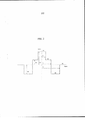
A figura 1 representa um corte transversal de uma fibra mono- modo com camadas de casca em respectivos raios que se estendem a partir do centro.Figure 1 represents a cross-section of a single-mode fiber with layers of bark in respective radii that extend from the center.
A figura 2 representa o perfil do índice de refração nominal da fibra monomodo exemplificativa da figura 1 de acordo com a presente inven- ção.Figure 2 represents the profile of the nominal refractive index of the exemplary single-mode fiber of Figure 1 according to the present invention.
A fibra 10 da invenção tem um núcleo central 11, uma casca in- termediária 12 e uma casca com depressão 13. Para as presentes finalida- des e sem limitar o escopo da invenção, casca com depressão significa uma porção radial da fibra 10, tendo um índice de refração menor do que o índice da casca ótica externa 14. Tipicamente, o núcleo central 11, a casca inter- mediária 12 e a casca com depressão 13 são obtidos por deposição química a vapor em um tubo de sílica. A casca ótica externa 14 inclui o tubo de sílica e a sobre-casca no tubo. Em modalidades preferidas, a sobre-casca, em ge- ral, é natural ou sílica dopada, mas também pode ser obtida por qualquer outra técnica de deposição (deposição axial a vapor) ("VAD") ou deposição a vapor externa ("OVD").The
A figura 2 ilustra um perfil do índice de refração para a fibra de transmissão 10 da figura 1. O perfil da figura 2 é um perfil estabelecido, isto é, representativo do perfil teórico da fibra, mas a fibra realmente obtida após o puxamento da fibra a partir de uma pré-forma pode ter um perfil ligeira- mente diferente.Figure 2 illustrates a profile of the refractive index for the
De maneira conhecida na técnica por si, uma fibra ótica 10 é ob- tida através do puxamento da pré-forma. À guisa de exemplo, a pré-forma pode ser um tubo de vidro de qualidade muito alta (sílica pura), que eventu- almente faz parte da casca ótica externa 14. A casca ótica externa 14 cir- cunda núcleo central 11 e as cascas internas 12, 13 da fibra 10. Esse tubo pode receber, então, uma sobre-casca para aumentar seu diâmetro antes de seguir com a operação de puxamento da fibra. Para a produção da pré- forma, o tubo, em geral, é montado horizontalmente e sustentado em ambas as extremidades por barras de vidro em um torno mecânico; então, o tubo é girado e aquecido localmente para o processo de deposição que determina a composição da pré-forma. Essa composição determina as características óticas da futura fibra.In a manner known in the art per se, an
A fibra inclui um grupo central 11, tendo uma diferença de índice Δni com uma casca externa 14 funcionando como uma casca ótica. A fibra 10 ainda inclui uma casca intermediária 12 tendo uma diferença de índice Δn2 com a casca ótica externa 14 e uma casca com depressão 13 tendo uma diferença de índice Δn3 com a casca ótica externa 14. Os índices de refração no núcleo central 11, da casca intermediária 12 e da depressão 13 são substancialmente constantes por todas as suas respectivas larguras, conforme apresentado na figura 12. A figura 1 ilustra que a largura do núcleo 11 é definida por seu raio n e a largura das cascas por seus respectivos rai- os externos r2 e r3. A casca ótica externa é denotada como r4.The fiber includes a core group 11, having a difference of Δni index with an
A fim de definir um perfil de índice de refração estabelecido para uma fibra ótica, o valor de índice da casca ótica externa é, em geral, tomadoIn order to define an established refractive index profile for an optical fiber, the index value of the external optical shell is, in general, taken
como uma referência nr Os valores de índice do núcleo central 11, a casca intermediária 12 e da casca com depressão 13 são, então, apresentados na figura 2 como diferenças de índice Δni,2.3. De um modo geral, a casca ótica externa 14 é composta de sílica, mas essa casca pode ser dopada para au- mentar ou reduzir seu índice de refração, por exemplo, para modificar as características de propagação do sinal.as a reference nr The index values of the central core 11, the
Cada seção de perfil de fibra mostrado na figura 2 (21 - 24) tam- bém pode ser definida com base em integrais que ligam as variações de ín- dice com o raio de cada seção da fibra 10. Desse modo, é possível definir três integrais de superfície para a fibra 10 da invenção, representativas da superfície do núcleo Voi, da superfície da casca intermediária V02 e da su- perfície da depressão V03. A expressão "superfície" não deve ser compreen- dida geometricamente, mas corresponde a um valor levando em considera- ção duas dimensões. Essas três integrais de superfície podem ser expres- sas como segue:
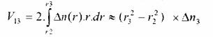
Similarmente, é possível definir três integrais de volume para a fibra 10 da invenção, representativas do volume do núcleo Vn, do volume da casca intermediária Vi2 e do volume da depresssão V13 • A expressão "Vo- lume" não deve ser compreendida geometricamente, mas corresponde a um valor que leva em conta três dimensões. Essas três integrais de volume po- dem ser expressas como segue:

A Tabela I (abaixo) mostra 30 exemplos de perfis de fibras de acordo com as modalidades preferidas da invenção em comparação com três perfis de fibras SSMF e um perfil de fibra correspondente a padrões 5 G.657A e G.657B (denotado como "BIF" para Bend Insensitive Fiber - Fibra insensível à curvatura). O requerente comercializa uma fibra insensível à curvatura tendo uma boa resistência às perdas por curvatura sob a marca comercial BendBrightXS. Os valores nas tabelas correspondem aos perfis estabelecidos para cada fibra.Table I (below) shows 30 examples of fiber profiles according to the preferred embodiments of the invention compared to three SSMF fiber profiles and a fiber profile corresponding to 5 G.657A and G.657B standards (denoted as "BIF "for Bend Insensitive Fiber - Fiber insensitive to curvature). The applicant markets a curvature-insensitive fiber having a good resistance to curvature losses under the BendBrightXS trademark. The values in the tables correspond to the profiles established for each fiber.
A primeira coluna da tabela 1 atribui uma referência para cada exemplo; as três colunas seguintes dão os valores correspondentes dos rai-os do núcleo 11, da casca intermediária 12 e da depressão 13, respectivamente. As três colunas seguintes dão os valores correspondentes das diferenças de índices com a casca ótica externa 14. Os valores de índice são 15 medidos em um comprimento de onda de 633 nanômetros. A tabela 1 também mostra os valores das integrais de superfície e de volume do núcleo 11, na casca intermediária 12 e da depressão 13, conforme definido acima.
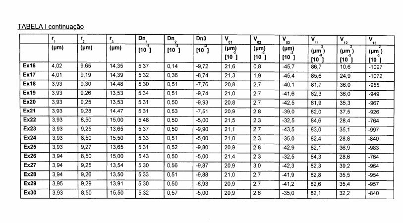
A fibra 10 de acordo com a invenção é uma fibra de índice degrau compreendendo núcleo central 11, uma casca intermediária 2 e uma depressão 13. Deve ser notado da tabela 1 que o núcleo central 11 tem um raio r1 entre 3,8 |im e 4,35 gm e, de preferência, entre 3,8 pm e 4,05 pm, isto é, mais estreito do que o núcleo de uma fibra SSMF. A fibra 10 tem uma diferença de índice Δn1 21 com a casca ótica externa 14 entre 5,3 x 10'3 e 5,7 x 10⁻³, isto é, maior do que em uma fibra SSMF. A integral de superfície do núcleo Voi está entre 20,0 x 10'3 pm e 23,0 x 10'3 pm, e a integral de volume do núcleo Vn está entre 81 x 10'3 pm2 e 91 x 10'3 pm2.The
Deve ser notado também da tabela 1 que a fibra de acordo com a invenção tem uma depressão 13. A depressão 13 tem um grande volume e torna possível limitar grandemente as perdas por curvatura. A tabela 1, mostra assim que a depressão 13 tem um raio r3 entre 13,5 pm e 16 pm e uma diferença de índice Δn3 23 com a casca ótica externa 14 entre -10,0 x 10’3 e -5,0 x 10'3.It should also be noted from Table 1 that the fiber according to the invention has a
A tabela 1 também mostra que a integral de superfície da depressão V03, conforme definido acima, está entre -55,0 x 10'3 pm e -30,0 x 10’3 pm e a integral de volume da depressão Vi3, conforme definido acima, está entre -1200 x 10’3 pm2e -750 x 10’3 pm2.Table 1 also shows that the surface integral of depression V03, as defined above, is between -55.0 x 10'3 pm and -30.0 x 10'3 pm and the volume integral of depression Vi3, as defined above, it is between -1200 x 10'3 pm2 and -750 x 10'3 pm2.
De acordo com uma modalidade preferida, o raio da casca com depressão r3 pode estar limitado a 15 pm, a fim de reduzir ainda o custo de produção da fibra (apenas os exemplos 24 e 30) têm uma casca com depressão, com raio maior do que 15 pm. De fato, a depressão 13 pode ser produzido por deposição química a vapor de plasma (PCVD), tornando possível incorporar uma grande quantidade de flúor na sílica para formar cascas com depressões profundas. A parte da fibra 10 que corresponde ao tubo e à deposição PCVD, porém, é a mais cara; portanto, busca-se limitar essa parte tanto quanto possível. Também é possível considerar a produção da depressão 13 através de incorporação de microfuros ou microbolhas em lugar de flúor dopado. O flúor dopado, porém, permanece mais fácil de controlar a produção industrial do que a incorporação de micro-bolhas.According to a preferred embodiment, the radius of the bark with depression r3 can be limited to 15 pm, in order to further reduce the cost of fiber production (only examples 24 and 30) have a bark with depression, with a radius greater than that 15 pm. In fact,
Uma depressão 13, que corresponde aos critérios de superfície e de volume, definidos acima, toma possível obter um bom compromisso entre perdas por curvatura grandemente reduzidas em relação às fibras exis- tentes e um regime de vazamento suficientemente consistente do modo LP11 em um comprimento de onda de 1260 nanômetros.A
Como está claro da Tabela IV, que é discutida em detalhes aqui depois, a fibra de acordo com a invenção tem perdas por curvatura que são dez vezes (10x) menores do que os limites impostos pelo padrão G.657B. Por outro lado, a fibra de acordo com a invenção não está rigorosamente em conformidade como o padrão G.657, em termos de comprimento de onda de corte. Como está claro da tabela III, que também é discutida em detalhes aqui depois, a fibra de acordo com a invenção de um comprimento de onda de corte efetivo Xceff maior do que 1350 nanômetros um comprimento de on- da de corte de cabo Xcc entre 1250 nanômetros e 1300 nanômetros. Não obstante, a fibra aqui divulgada assegura que modos LP11 de ordem superi- or são propagados no regime de vazamento de modo de 1260 nanômetros.As is clear from Table IV, which is discussed in detail hereinafter, the fiber according to the invention has curvature losses that are ten times (10x) less than the limits imposed by the G.657B standard. On the other hand, the fiber according to the invention does not strictly conform to the G.657 standard, in terms of cutting wavelength. As is clear from Table III, which is also discussed in detail here after, the fiber according to the invention of an effective Xceff shear wavelength greater than 1350 nanometers an Xcc cable shear wavelength between 1250 nanometers and 1300 nanometers. Nevertheless, the fiber disclosed here ensures that LP11 modes of higher order are propagated in the 1260 nanometer mode leakage regime.
Também deve ser notado da tabela 1 que uma modalidade pre- ferida da fibra tem uma casca intermediária 12 entre o núcleo central 11 e a depressão 13. Esta casca intermediária 12 torna possível limitar os efeitos da depressão 13 sobre a propagação do sinal ótico no núcleo. A tabela 1 mostra que a casca intermediária 12 tem um raio r2 entre 8,5 pm e 9,7 pm e uma diferença de índice Δn2 22 com a casca ótica entre 0,1 x 10'3 e 0,6 x 10'3. A tabela I mostra que a integral de superfície da casca intermediária V02, como definido acima, está entre 0,5 x 10'3 pm e 3,0 x 10‘3 pm. A integral de volume da casca intermediária Vi2, como definida acima, está entre 6 x 10'3 pm2 e 4- x 10 10'3 pm2.It should also be noted from Table 1 that a preferred fiber modality has an
O núcleo central 11 de uma fibra 10 de acordo com a invenção é otimizado, em combinação com a casca intermediária 12 para garantir pa- râmetros de transmissão ótica na fibra em conformidade com os padrões G.652 e G.657A, particularmente em termos de diâmetro do campo do modo e dispersão cromática. Isso também ajuda a segurar a compatibilidade com as fibras de outros sistemas óticos.The central core 11 of a
A Tabela II abaixo mostra as características de transmissão ótica para fibras de acordo com a invenção. A primeira coluna repete as referências da tabela 1. As colunas seguintes proporcionam, para cada perfil de fibra, os valores de diâmetro do campo do modo (MFD) para comprimentos de onda de 1310 nanômetros e 1550 nanômetros, comprimento de onda de 5 dispersão cromática zero (ZDW) e inclinação de dispersão zero (ZDS).
Deve ser notado da tabela 2 que a fibra 10 de acordo com a in- venção é compatível com fibras que correspondem aos critérios do padrão G.652. Em particular, a fibra aqui divulgada tem um diâmetro de campo mo- dal MFD na faixa padronizada de valores de 8,6 pm a 9,5 pm, em 1310 na- nômetros, um comprimento de onda de dispersão zero entre 1300 nanôme- tros e 1324 nanômetros e uma inclinação de dispersão erro de menos do que 0,092 ps/(nm2 km). Cada um desses valores está de acordo com o pa- drão G.652.It should be noted from Table 2 that
Por outro lado, conforme mostrado pela Tabela III (abaixo), a fibra tem um comprimento de onda de corte A.cetf efetivo maior do que 1350 nanômetros. Como discutido acima, o comprimento de onda de corte é me- dido como sendo o comprimento de onda em que o sinal ótico não está mais no modo único após a propagação através de dois metros de fibra, tal como definido pelo Subcommittee 86A da International Electrotechnical Commis- sion no padrão IEC 60793-44. Este valor de comprimento de onda de corte efetivo aumentado conduz a um valor de comprimento de onda de corte de cabo Àcc entre 1250 nanômetros e 1300 nanômetros. O comprimento de on- da de corte do cabo é medido como o comprimento de onda no qual o sinal ótico não está mais em modo único após a propagação através de 22 metros de fibra, como definido pelo subcommittee 86A da International Electrotech- nical Commission no padrão IEC 60793-1-44. O sinal ótico é de modo único quando a atenuação do modo LP11 é maior do que ou igual a 19,3 dB. Os padrões G.652 e G.657 impõem um valor máximo de 1260 nanômetros para o comprimento de onda de corte do cabo.On the other hand, as shown in Table III (below), the fiber has an effective A. cetf cutting wavelength greater than 1350 nanometers. As discussed above, the cut-off wavelength is measured to be the wavelength at which the optical signal is no longer in single mode after propagation through two meters of fiber, as defined by Subcommittee 86A of International Electrotechnical Commission in the IEC 60793-44 standard. This increased effective cutting wavelength value leads to an Àcc cable cutting wavelength value between 1250 nanometers and 1300 nanometers. The cable's wavelength is measured as the wavelength at which the optical signal is no longer in single mode after propagating through 22 meters of fiber, as defined by subcommittee 86A of the International Electrotechnical Commission in IEC 60793-1-44 standard. The optical signal is unique when the attenuation of the LP11 mode is greater than or equal to 19.3 dB. The G.652 and G.657 standards impose a maximum value of 1260 nanometers for the cable cutting wavelength.
Uma finalidade dos desenvolvimentos aqui divulgados é produzir fibras que podem ser usadas em todas as larguras de banda de transmissão exploradas por sistemas óticos, isto é, fibras que podem ser usadas em pro- pagação de modo único a partir da largura de banda original (OB), que se estende de 1260 nanômetros até 1360 nanômetros e até a largura de banda ultralonga (Ul_) além de 1625 nanômetros. Um comprimento de onda de cor- te baixo torna possível garantir a possibilidade de uso da fibra através de todas as larguras de banda disponíveis.One purpose of the developments disclosed here is to produce fibers that can be used in all transmission bandwidths exploited by optical systems, that is, fibers that can be used in single mode propagation from the original bandwidth (OB ), which extends from 1260 nanometers to 1360 nanometers and up to the ultra-long bandwidth (Ul_) in addition to 1625 nanometers. A short cut wavelength makes it possible to guarantee the possibility of using the fiber across all available bandwidths.
As simulações da Tabela III (abaixo), porém, mostram que o modo de LP11 de ordem diretamente superior é propagado de acordo com um modo vazante a partir de um comprimento de onda de 1260 nanômetros. A fibra aqui divulgada pode, portanto, ser usada em transmissão de modo único através da largura de banda original (OB: 1260 nanômetros a 1360 nanômetros).The simulations in Table III (below), however, show that the LP11 mode of directly higher order is propagated according to a receding mode from a wavelength of 1260 nanometers. The fiber disclosed here can therefore be used in single mode transmission over the original bandwidth (OB: 1260 nanometers to 1360 nanometers).
A Tabela III (abaixo) mostra diversos valores de comprimentos de onda de corte para fibras de acordo com a invenção. A primeira coluna da Tabela III repete as referências da Tabela I.Table III (below) shows various values of cutting wavelengths for fibers according to the invention. The first column of Table III repeats the references in Table I.
A coluna "Corte de Fibra Teórico" proporciona um valor teórico de comprimento de onda de corte, que corresponde ao comprimento de on- da de transição entre uma propagação guiada do modo LP11 e uma propa- gação em modo vazante desse modo LP11. Para trabalhar comprimentos de onda além desse comprimento de onda de corte efetivo, o modo LP11 é propagado em modo vazante.The "Theoretical Fiber Cutting" column provides a theoretical value for the cutting wavelength, which corresponds to the transition wave length between a guided propagation of the LP11 mode and an outflow propagation of the LP11 mode. To work on wavelengths beyond that effective cutting wavelength, LP11 mode is propagated in ebb mode.
A coluna "Corte de Fibra Padrão" corresponde ao comprimento de onda de corte efetivo Xcetf como definido pelo Subcommittee 86A da Inter- national Electrotechnical Commission no padrão IEC 60793-1-44.The "Standard Fiber Cutting" column corresponds to the effective cutting wavelength Xcetf as defined by Subcommittee 86A of the International Electrotechnical Commission in the IEC 60793-1-44 standard.
A coluna "Corte de Fibra de 5m" corresponde ao comprimento de onda de corte medido como o comprimento de onda em que o sinal ótico não está mais no modo único após propagação através de 5 metros de fibra em lugar de 2 metros de fibra.The "5m Fiber Cut" column corresponds to the cut wavelength measured as the wavelength at which the optical signal is no longer in single mode after propagation through 5 meters of fiber instead of 2 meters of fiber.
A coluna "Corte de Cabo Padrão" corresponde ao comprimento de onda de corte do cabo kcc como definido pelo Subcommittee 86A da In- ternational Electrotechnical Commission no padrão IEC 60793-1-44. De a- cordo com a recomendação do Subcommittee 86A da International Electro- technical Commission no padrão IEC 60793-1-44, o comprimento de onda de corte do cabo Àcc é determinado pelo posicionamento da fibra em dois laços de 40 milímetros de raio e pela disposição do restante da fibra (isto é, 21,5 metros de fibra) em um mandril com um raio de 140 milímetros.The "Standard Cable Cut" column corresponds to the cut-off wavelength of the kcc cable as defined by Subcommittee 86A of the International Electrotechnical Commission in the IEC 60793-1-44 standard. According to the recommendation of Subcommittee 86A of the International Electro-technical Commission in the IEC 60793-1-44 standard, the cutting wavelength of the Àcc cable is determined by the positioning of the fiber in two 40 mm radius loops and by the disposition of the rest of the fiber (that is, 21.5 meters of fiber) in a mandrel with a radius of 140 millimeters.
A coluna "Corte de Cabo Reto" corresponde ao comprimento de onda de corte de cabo pelo posicionamento da fibra em dois laços, cada um tendo um raio de 40 milímetros e pela disposição do restante da fibra (isto é, 21,5 metros de fibra) virtualmente reta.The "Straight Cable Cut" column corresponds to the cable cut wavelength by positioning the fiber in two loops, each having a radius of 40 millimeters and by arranging the rest of the fiber (that is, 21.5 meters of fiber ) virtually straight.
A coluna "LP11 LL LL @ 1260 nm após 22 mm" indica as fendas por vazamento do modo LP11 após a propagação através de 22 metros da 5 fibra virtualmente reta.The column "LP11 LL LL @ 1260 nm after 22 mm" indicates the leakage cracks in the LP11 mode after propagation through 22 meters of the virtually straight fiber.
A coluna "Comprimento - 19,3 dB LP11 LL @1260 nm" indica o comprimento da fibra requerido para obter perdas por vazamento do modo LP11 igual a 19,3 dB, com a fibra sendo mantida virtualmente reta. Isso indica em que distância a fibra, disposta virtualmente reta, está no modo único dentro do significado dos padrões G.652 e G.657.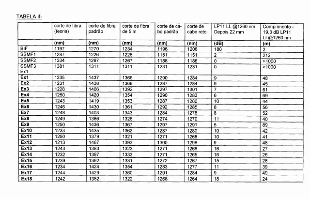
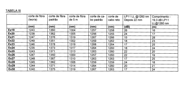
É notado da Tabela III que o comprimento de onda de corte efetivo padrão Xcetf, isto é, conforme medido de acordo com as recomendações do Subcommittee 86A da International Electrotechnical Commission no padrão IEC 60793-1-44 é maior do que 1350 nm. Similarmente, é notado da Tabela III que o comprimento de onda de corte de cabo padrão Xcc, isto é, conforme medido de acordo com as recomendações do Subcommittee 86A do International Electrotechnical Commission no padrão IEC 60793-44, está entre 1250 nanômetros e 1300 nanômetros, isto é, frequentemente maior do que o limite de 1260 nanômetros, imposto pelos padrões G.652 e G.657.It is noted from Table III that the effective cutting wavelength Xcetf standard, that is, as measured according to the recommendations of Subcommittee 86A of the International Electrotechnical Commission in the IEC 60793-1-44 standard is greater than 1350 nm. Similarly, it is noted from Table III that the Xcc standard cable cutting wavelength, that is, as measured according to the recommendations of Subcommittee 86A of the International Electrotechnical Commission in the IEC 60793-44 standard, is between 1250 nanometers and 1300 nanometers , that is, often higher than the limit of 1260 nanometers, imposed by the G.652 and G.657 standards.
Porém, é observado da Tabela III que o modo LP11 não obstante, é altamente atenuado a partir de um comprimento de onda de 1260 nanômetros. De fato, o comprimento de onda de corte "teórico" é menor do que ou igual a 1250 nanômetros. Desse modo, o modo LP11 de ordem superior é propagado em um regime de modo vazante na largura de banda original e apenas o modo fundamental permanece guiado na fibra da invenção como de um comprimento de onda de 1260 nanômetros.However, it is observed from Table III that the LP11 mode is nevertheless highly attenuated from a wavelength of 1260 nanometers. In fact, the "theoretical" cutting wavelength is less than or equal to 1250 nanometers. In this way, the LP11 mode of higher order is propagated in a low-mode regime in the original bandwidth and only the fundamental mode remains guided in the fiber of the invention as having a wavelength of 1260 nanometers.
Similarmente, é notado da Tabela III que o comprimento de onda de corte de fibra é reduzido, significativamente, após apenas 5 metros de propagação na fibra. Desse modo, o comprimento de onda de corte, medido como o comprimento de onda em que o sinal ótico não está mais no modo único após a propagação através de 5 metros de fibra, está entre 1300 nanômetros e 1400 nanômetros para uma fibra de acordo com a invenção.Similarly, it is noted from Table III that the fiber cutting wavelength is significantly reduced after only 5 meters of propagation in the fiber. Thus, the cut-off wavelength, measured as the wavelength at which the optical signal is no longer in single mode after propagation through 5 meters of fiber, is between 1300 nanometers and 1400 nanometers for a fiber according to the invention.
Além disso, a Tabela III mostra claramente que o modo de LP11 já está bem atenuado após 22 metros de propagação. É notado em particular que a atenuação do modo LP11 em uma fibra 10 de acordo com a presente invenção é maior do que a atenuação do modo LP11 em uma fibra SSMF, quando a fibra é disposta virtualmente reta. De fato, em uma fibra SSMF, são as curvaturas que tornam possível atenuar, altamente, o modo LP11. Desse modo, a fibra tem uma atenuação do modo LP11 maior do que 5 dB após 22 metros de propagação em fibra reta em um comprimento de onda de 1260 nanômetros.In addition, Table III clearly shows that the LP11 mode is already well attenuated after 22 meters of propagation. It is noted in particular that the attenuation of the LP11 mode on a
Além disso, a Tabela III também mostra que a atenuação de pe- lo menos 19,3 dB do modo LP11 é obtida de modo relativamente rápido, a- pós menos do que 90 metros, em vez dos 22 metros impostos pelos padrões.In addition, Table III also shows that the attenuation of at least 19.3 dB in LP11 mode is achieved relatively quickly, after less than 90 meters, instead of the 22 meters imposed by the standards.
Desse modo, a falha em estar em conformidade, no sentido mais estrito, com os padrões G.652 e G.657 em termos de comprimento de onda de corte é minimizada pelo fato de que o modo LP11 de ordem superior é atenuado suficientemente a partir de um comprimento de onda de 1260 nanômetros de modo a não prejudicar a qualidade da propagação do modo fundamental.In this way, failure to comply, in the strictest sense, with the G.652 and G.657 standards in terms of cutting wavelength is minimized by the fact that the higher-order LP11 mode is attenuated sufficiently from of a wavelength of 1260 nanometers so as not to impair the quality of propagation in the fundamental way.
Além disso, o aumento no comprimento de onda de corte efetivo torna possível aumentar o valor do MAC como definido acima e, consequentemente, reduzir as perdas por curvatura.In addition, the increase in the effective cutting wavelength makes it possible to increase the MAC value as defined above and, consequently, to reduce losses due to curvature.
A Tabela IV (abaixo) relata valores de perdas por curvatura para modalidades preferidas de fibras, conforme aqui divulgado. A primeira coluna da Tabela IV repete as referências da Tabela 1. As quatro colunas seguintes mostram valores de perdas por curvatura PPC para respectivos raios de curvatura de 15 milímetros, 10 milímetros, 7,5 milímetros e 5 milímetros em um comprimento de onda de 1550 nanômetros. As quatro colunas seguintes dão valores de perdas por curvatura PPC para respectivos raios de curvatura de 15 milímetros, 10 milímetros, 7,5 milímetros e 5 milímetros em um comprimento de onda de 1625 nanômetros.Table IV (below) reports values of losses due to curvature for preferred fiber modalities, as disclosed here. The first column of Table IV repeats the references in Table 1. The following four columns show values of PPC curvature losses for the respective radii of curvature of 15 mm, 10 mm, 7.5 mm and 5 mm at a wavelength of 1550 nanometers. The following four columns give PPC curvature loss values for respective radii of curvature of 15 mm, 10 mm, 7.5 mm and 5 mm at a wavelength of 1625 nanometers.
A última coluna tem um fator de mérito FOM representando a ordem de magnitude do aperfeiçoamento nas perdas por curvatura pelas fibras de acordo com a presente invenção em relação aos limites impostos pelo padrão G.657B. O FOM da Tabela IV é, assim, definido como uma média das relações entre os limites superiores impostos pelo padrão G.657B e as perdas por curvatura nas fibras da invenção para cada raio de curvatura medido.The last column has an FOM merit factor representing the order of magnitude of the improvement in losses due to curvature by the fibers according to the present invention in relation to the limits imposed by the G.657B standard. The FOM in Table IV is thus defined as an average of the relationships between the upper limits imposed by the G.657B standard and the curvature losses in the fibers of the invention for each measured radius of curvature.
A Tabela IV relata na primeira linha os valores limites de perdas por curvatura impostos pelo padrão G.657B para cada raio de curvatura e para os comprimentos de onda de 1550 nanômetros e 1625 nanômetros.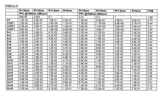

É notado da Tabela IV que as perdas por curvatura das fibras correspondentes ao perfil de acordo com a invenção são claramente menores do que os limites impostos pelo padrão G.657B.It is noted from Table IV that the curvature losses of the fibers corresponding to the profile according to the invention are clearly less than the limits imposed by the G.657B standard.
Desse modo, a fibra divulgada acima tem, para um comprimento de onda de 1550 nanômetros, perdas por curvatura menores do que 0,25 x 10'3dB/ curva para um raio de curvatura de 15 milímetros, quando comparado com um limite de 3 x 10'3 dB/ curva, imposto pelo padrão G.657B. A fibra ainda tem perdas por curvatura menores do que ou iguais a 7,5 x 10'3 dB/ vez para um raio de curvatura de 10 milímetros, quando comparado com um limite de 0,1 dB/curva, imposto pelo padrão G.657B. As perdas por curvatura são menores do que ou iguais a 0,05 dB/ curva para um raio de curvatura de 7,5 milímetros, como contra um limite de 0,5 dB/ curva imposto pelo padrão G.657B e perdas por curvatura menores do que 0,15 dB/ curva para um raio de curvatura de 5 milímetros.Thus, the fiber disclosed above has, for a wavelength of 1550 nanometers, losses of curvature less than 0.25 x 10'3dB / curve for a radius of curvature of 15 millimeters, when compared to a limit of 3 x 10'3 dB / curve, imposed by the G.657B standard. The fiber still has curvature losses less than or equal to 7.5 x 10'3 dB / time for a radius of curvature of 10 millimeters, when compared to a limit of 0.1 dB / curve, imposed by the G standard. 657B. Curvature losses are less than or equal to 0.05 dB / curve for a radius of curvature of 7.5 mm, as against a limit of 0.5 dB / curve imposed by the G.657B standard and lower curvature losses than 0.15 dB / curve for a radius of curvature of 5 mm.
As perdas por curvatura em um comprimento de onda de 1550 nanômetros em uma fibra de acordo com a invenção têm sido aperfeiçoadas por um fator maior do que 10X em relação aos limites do padrão G.657B.The curvature losses at a wavelength of 1550 nanometers in a fiber according to the invention have been improved by a factor greater than 10X in relation to the limits of the G.657B standard.
Similarmente, a fibra de acordo com a invenção mostra, para um comprimento de onda de 1625 nanômetros, perdas por curvatura menores do que 1,5 x 10'3 dB/ curva, quando comparado co um limite de 10 x 10'3 dB/ curva, imposto pelo padrão G.657B. As perdas por curvatura são menores do que ou iguais 25 x 10 3 dB/ curva para um raio de curvatura de 10 milímetros, quando comparado com um limite de 0,2 dB/ curva, imposto pelo padrão G.657B. A fibra mostra perdas por curvatura menores ou iguais a 0,08 dB/ curva para um raio de curvatura de 7,5 milímetros, comparado com um limite de 1 dB/ curva, imposto pelo padrão G.657B e perdas por curvatura menores do que 0,25 dB/ curva para um raio de curvatura de 5 milímetros.Similarly, the fiber according to the invention shows, for a wavelength of 1625 nanometers, curvature losses less than 1.5 x 10'3 dB / curve, when compared to a limit of 10 x 10'3 dB / curve, imposed by the G.657B standard. The curvature losses are less than or equal to 25 x 10 3 dB / curve for a radius of curvature of 10 millimeters, when compared to a limit of 0.2 dB / curve, imposed by the G.657B standard. The fiber shows curvature losses less than or equal to 0.08 dB / curve for a curvature radius of 7.5 millimeters, compared to a limit of 1 dB / curve, imposed by the G.657B standard and curvature losses less than 0.25 dB / curve for a radius of curvature of 5 mm.
As perdas por curvatura em um comprimento de onda de 1625 nanômetros em uma fibra de acordo com a invenção foram aperfeiçoadas por um fator de 10 em relação aos limites do padrão G.657B. Deve ser notado que, dentro da estrutura de uma produção industrial de pré-formas de fibra ótica, os testes de conformidade, vis-à-vis com os padrões, são realiza dos levando-se em consideração apenas cifras significativas indicadas no padrão. Desse modo, quando o padrão G.657B impõe o valor limite de 0,01 dB/ curva em um comprimento de onda de 1625 nanômetros para um raio de curvatura de 15 milímetros, o fabricante tolerará perdas por curvatura oscilando até 0,014 dB/ curva nesse comprimento de onda para esse raio de curvatura. As perdas por curvatura menores do que 1,5 x 10’3 dB/ curva para um raio de curvatura de 15 milímetros em um comprimento de onda de 1625 nanômetros (isto é, a fibra de acordo com a presente invenção) são, portanto, pelo menos dez vezes melhores do que os limites impostos pelo padrão.The curvature losses at a wavelength of 1625 nanometers in a fiber according to the invention have been improved by a factor of 10 in relation to the limits of the G.657B standard. It should be noted that, within the framework of an industrial production of optical fiber preforms, compliance tests, vis-à-vis standards, are carried out taking into account only significant figures indicated in the standard. Thus, when the G.657B standard imposes a limit value of 0.01 dB / curve at a wavelength of 1625 nanometers for a radius of curvature of 15 millimeters, the manufacturer will tolerate losses by curvature oscillating up to 0.014 dB / curve in that wavelength for that radius of curvature. Curvature losses less than 1.5 x 10'3 dB / curve for a curvature radius of 15 mm at a wavelength of 1625 nanometers (ie, the fiber according to the present invention) are therefore at least ten times better than the limits imposed by the standard.
A coluna FOM da Tabela IV mostra que as fibras da invenção, claramente, aperfeiçoaram as perdas por curvatura relativas às fibras de BIF existentes, que correspondem às exigências do padrão G.657B.The FOM column of Table IV shows that the fibers of the invention clearly improved the curvature losses relative to the existing BIF fibers, which meet the requirements of the G.657B standard.
As fibras aqui divulgadas são bem adequadas a um uso em sistemas óticos instalados na casa do assinante, do tipo FTTH, em que a fibra é submetida a tensões de curvatura significativas devido à miniaturização da caixa ótica ou a manutenção da fibra no lugar com grampos. A fibra pode ser colocada em caixas óticas particularmente compactas. De fato, a fibra ótica pode ser disposta com um raio de curvatura de menos do que 15 milímetros, por exemplo, um raio de curvatura de cerca de 5 milímetros. A fibra permanece compatível com as fibras de sistemas existentes, em particular em termos de diâmetro do campo do modo para bom acoplamento de fibra com fibra. O aumento no comprimento de onda de corte não é prejudicial devido a uma atenuação significativa do modo LP11 de um comprimento de onda de 1260 nanômetros.The fibers disclosed here are well suited for use in optical systems installed at the subscriber's home, of the FTTH type, in which the fiber is subjected to significant bending stresses due to the miniaturization of the optical box or the keeping of the fiber in place with clamps. The fiber can be placed in particularly compact optical boxes. In fact, the optical fiber can be arranged with a radius of curvature of less than 15 millimeters, for example, a radius of curvature of about 5 millimeters. The fiber remains compatible with the fibers of existing systems, in particular in terms of the field diameter of the mode for good fiber-to-fiber coupling. The increase in the cutting wavelength is not harmful due to a significant attenuation of the LP11 mode of a wavelength of 1260 nanometers.
Conforme apresentado no Pedido de Patente dos Estados Unidos N° 60/986.737, para uma Microbend-Resistant Optical Fiber (Overton) e Pedido de Patente dos Estados Unidos N° 61/041.484, para uma Microbend- Resistant Optical Fiber (Overton), cada um dos quais é aqui incorporado a- través de referência em sua totalidade, emparelhando uma fibra de vidro insensível à curvatura (por exemplo, fibras de vidro monomodo da Draka Comteq, disponíveis sob a marca de comércio e indústria BendBrightxs®) e uma casca primário tendo módulo muito baixo (por exemplo, produto de acri- lato de uretano curável por UV de DSM Desotech’s, fornecido sob a marca de comércio e indústria DeSolite® DP 1011) obtêm-se fibras óticas tendo perdas excepcionalmente baixas (por exemplo, reduções em sensitívidade à microcurvatura de pelo menos 10X, quando comparado com uma fibra mo- nomodo, empregando um sistema de casca convencional). Em consequência, ainda está dentro do escopo da presente invenção empregar os cascas divulgados no Pedido de Patente dos Estados Unidos N° 60/986.737 e Pedido de Patente dos Estados Unidos N° 61/041.484 com a fibra ótica mono- modo da presente invenção.As presented in United States Patent Application No. 60 / 986,737, for a Microbend-Resistant Optical Fiber (Overton) and United States Patent Application No. 61 / 041,484, for a Microbend-Resistant Optical Fiber (Overton), each one of which is incorporated here by reference in its entirety, pairing a curvature-insensitive glass fiber (eg Draka Comteq single-mode glass fibers, available under the trademark and industry brand BendBrightxs®) and a primary shell having very low modulus (for example, DSM Desotech's UV-curable urethane acrylate product, supplied under the trade and industry brand DeSolite® DP 1011) optical fibers are obtained with exceptionally low losses (for example, reductions in sensitivity to microcurvature of at least 10X, when compared to a modern fiber, employing a conventional shell system). Consequently, it is still within the scope of the present invention to employ the shells disclosed in United States Patent Application No. 60 / 986,737 and United States Patent Application No. 61 / 041,484 with the single-mode optical fiber of the present invention.
Com relação a isso, a microcurvatura pode ser analisada de a- cordo com o teste do tambor de lixa de diâmetro fixo do IEC (isto é, papel de lixa de grau 4 microns, Método B, IEC TR62221), que proporciona uma situação de tensão de microcurvatura, que afeta fibras monomodo, mesmo em temperatura ambiente. O relatório técnico e procedimentos de teste padrão de sensitívidade à microcurvatura TR62221 do IEC (por exemplo, IEC TR62221, Método B. (tambor de papel de lixa de diâmetro fixo) e Método D (fundo de cesta)) são aqui incorporados através de referência em sua totalidade.In this regard, the microcurvature can be analyzed according to the IEC fixed diameter sand drum test (ie, 4 micron grade sand paper, Method B, IEC TR62221), which provides a situation of microcurvature tension, which affects single-mode fibers, even at room temperature. The technical report and standard test procedures for IEC TR62221 microcurvature sensitivity (for example, IEC TR62221, Method B. (sandpaper paper drum) and Method D (basket bottom)) are hereby incorporated by reference in its entirety.
O presente pedido ainda incorpora inteiramente através de referência as patentes comumente atribuídas, pedidos de patente e publicações de pedidos de patente a seguir, cada um dos quais discute as fibras óticas: patente norte-americana N° 4.838.643 para Single Mode Bend Insensitive Fiber for Use in Fiber Optic Guidance Applications (Hodges e outros); Publicação de Pedido de Patente dos Estados Unidos N° 2007/ 0127878 A1 e seu Pedido de Patente dos Estados Unidos N° 11/ 556.895 relacionado para uma Single Mode Optical Fiber (de Montmorillon e outros); Publicação de Pedido de Patente dos Estados Unidos N° US 2007/0280615 A1 e seu Pedido de Patente dos Estados Unidos N° 11/ 697.994 relacionado para SingleMode Optical Fiber (de Montmorillon e outros); patente norte-americana N° 7.356.234 e seu Pedido de Patente dos Estados Unidos N° 11/743.365 relacionado para Chromatic Dispersion Compensating Fiber (de Montmorillon e outros); Publicação de Pedido de Patente dos Estados Unidos N° US 2008/0152288 A1 e seu Pedido de Patente dos Estados Unidos N° 11/999.333 relacionado para uma Optical Fiber (Flammer e colaboradores.)', e Pedido de Patente dos Estados Unidos N° 61/ 101.337 para uma Single Mode Optical Fiber (de Montmorillon e outros).The present application further incorporates by reference the following commonly assigned patents, patent applications and patent application publications, each of which discusses optical fibers: US Patent No. 4,838,643 for Single Mode Bend Insensitive Fiber for Use in Fiber Optic Guidance Applications (Hodges and others); United States Patent Application Publication No. 2007/0127878 A1 and United States Patent Application No. 11 / 556,895 related to a Single Mode Optical Fiber (by Montmorillon et al.); United States Patent Application Publication No. US 2007/0280615 A1 and United States Patent Application No. 11 / 697,994 related to SingleMode Optical Fiber (by Montmorillon et al.); United States Patent No. 7,356,234 and United States Patent Application No. 11 / 743,365 related to Chromatic Dispersion Compensating Fiber (by Montmorillon et al.); United States Patent Application Publication No. US 2008/0152288 A1 and its United States Patent Application No. 11 / 999,333 related to an Optical Fiber (Flammer et al.) ', And United States Patent Application No. 61 / 101.337 for a Single Mode Optical Fiber (by Montmorillon and others).
A fibra ótica de acordo com a presente invenção pode ainda incluir uma ou mais camadas de casca (por exemplo, uma casca primário e uma casca secundário). Pelo menos uma das camadas de casca - tipicamente a casca secundário - pode ser colorido e/ou possuir outras marcações para ajudar a identificar fibras individuais. De modo alternativo, uma camada de tinta terciária pode circundar os cascas primário e secundário.The optical fiber according to the present invention can further include one or more layers of shell (for example, a primary shell and a secondary shell). At least one of the shell layers - typically the secondary shell - can be colored and / or have other markings to help identify individual fibers. Alternatively, a layer of tertiary paint can surround the primary and secondary peels.
A fibra ótica de acordo com a presente invenção pode ser empregada em várias estruturas, tais como aquelas estruturas exemplificativas aqui divulgadas depois.The optical fiber according to the present invention can be used in various structures, such as those exemplary structures disclosed hereinafter.
Por exemplo, uma ou mais das presentes fibras óticas podem ser encerradas no interior de um tubo de proteção. Por exemplo, a fibra ótica pode ser colocada ou em um tubo de proteção de fibra única solta ou em um tubo de proteção de fibras múltiplas soltas. Com relação a este último, fibras óticas múltiplas podem ser enfeixadas ou torcidas dentro de um tubo de proteção ou outra estrutura. Com relação a isso, dentro de um tubo de proteção, fibras múltiplas soltas, sub-feixes de fibras podem ser separados com um aglutinante (por exemplo, cada subfeixe de fibras é envolvido em um aglutinante. Além disso, tubo para facilitar conectorização ("fan-out tube") pode ser instalado na terminação desses tubos de proteção com folga, para terminar, diretamente, fibras óticas protegida, soltas, com os conectores instalados no campo.For example, one or more of the present optical fibers can be enclosed within a protective tube. For example, the optical fiber can be placed either in a loose single fiber protection tube or in a loose multiple fiber protection tube. With respect to the latter, multiple optical fibers can be bundled or twisted into a protective tube or other structure. In this regard, inside a protective tube, multiple loose fibers, sub-bundles of fibers can be separated with a binder (for example, each sub-bundle of fibers is wrapped in a binder. In addition, a tube to facilitate connectorization (" fan-out tube ") can be installed at the termination of these protective tubes loosely, to directly terminate protected optical fibers, loose, with the connectors installed in the field.
Em outras modalidades, o tubo de proteção pode circundar, a- pertadamente, a casca de fibra ótica mais externo (isto é, fibra protegida a- pertada), ou de outro modo, circundar a casca de fibra ótica mais externo ou camada de tinta para proporcionar uma folga radial exemplificativa de entre cerca de 50 e 100 microns (isto é, uma fibra armazenada semiapertada).In other embodiments, the protective tube may properly surround the outermost optical fiber shell (ie, protected protected fiber), or otherwise, surround the outermost optical fiber shell or paint layer. to provide an exemplary radial clearance of between about 50 and 100 microns (i.e., a semi-tight stored fiber).
Com relação à fibra protegida, apertada, anterior, a proteção pode ser formado por revestindo-se a fibra ótica com uma composição curável (por exemplo, um material curável por UV) ou um material termoplástico. O diâmetro externo dos tubos de proteção, apertados, independente de se o tubo de proteção é formado de um material curável ou não curável, tipicamente, é menor do que cerca de 1.000 microns (por exemplo, cerca de 500 microns ou cerca de 900 microns).With respect to the protected, tight, anterior fiber, the protection can be formed by coating the optical fiber with a curable composition (for example, a UV curable material) or a thermoplastic material. The outer diameter of the tightened protective tubes, regardless of whether the protective tube is formed of a curable or non-curable material, is typically less than about 1,000 microns (for example, about 500 microns or about 900 microns ).
Com relação à última fibra protegida, semiapertada, um lubrificante pode ser incluído entre a fibra ótica e o tubo de proteção (por exemplo, para proporcionar uma camada de deslizamento).With respect to the last protected, semi-tightened fiber, a lubricant can be included between the optical fiber and the protective tube (for example, to provide a slip layer).
Como será conhecido por aqueles tendo habilidade comum na técnica, um tubo de proteção exemplificativo encerrando fibras óticas como aqui divulgado pode ser formado de poliolefinas (por exemplo, polietileno ou polipropileno), incluindo poliolefinas fluoradas, poliésteres (por exemplo, te- reftalato de polibutileno), poliamidas (por exemplo, náilon), bem como outros materiais poliméricos e combinações. Em geral, um tubo de proteção pode ser formado de uma ou mais camadas. As camadas podem ser homogêneas ou incluir misturas ou combinações. Em geral, um tubo de proteção pode ser formado de uma ou mais camadas. As camadas podem ser homogêneas ou incluir misturas ou combinações de vários materiais dentro de cada camada.As will be known to those of ordinary skill in the art, an exemplary protective tube enclosing optical fibers as disclosed herein may be formed of polyolefins (for example, polyethylene or polypropylene), including fluorinated polyolefins, polyesters (for example, polybutylene tephthalate) ), polyamides (for example, nylon), as well as other polymeric materials and combinations. In general, a protective tube can be formed of one or more layers. The layers can be homogeneous or include mixtures or combinations. In general, a protective tube can be formed of one or more layers. The layers can be homogeneous or include mixtures or combinations of various materials within each layer.
Neste contexto, o tubo de proteção pode ser extrudado (por e- xemplo, um material polimérico extrudado) ou pultruído (por exemplo, um plástico reforçado com fibra pultruído. À guisa de exemplo, o tubo de proteção pode incluir um material para proporcionar alta temperatura e resistência química (por exemplo, um material aromático ou material de polissulfona).In this context, the protective tube can be extruded (for example, an extruded polymeric material) or pultruded (for example, a fiber-reinforced plastic with a pultruded fiber. For example, the protective tube can include a material to provide high temperature and chemical resistance (for example, an aromatic material or polysulfone material).
Embora tubos de proteção, tipicamente, tenham uma seção transversal circular, tubos de proteção, alternativamente, podem ter uma forma irregular ou não circular (por exemplo, uma seção transversal oval ou trapezoidal).Although protective tubes typically have a circular cross section, protective tubes, alternatively, may be irregular or non-circular in shape (for example, an oval or trapezoidal cross section).
De modo alternativo, uma ou mais das presentes fibras óticas podem ser, simplesmente, circundadas por uma capa protetora externa ou encapsuladas dentro de um tubo de metal selado. Em ambas as estruturas, nenhum tubo de proteção é requerido, necessariamente.Alternatively, one or more of the present optical fibers can simply be surrounded by an external protective cap or encapsulated within a sealed metal tube. In both structures, no protective tube is required, necessarily.
Fibras óticas múltiplas, conforme aqui divulgado podem ser in- tercaladas, encapsuladas e/ou bordas ligadas para formar uma fita de fibras óticas. As fitas de fibras óticas podem ser divisíveis em subunidades (por exemplo, uma fita de doze fibras que é dividida em subunidades de seis fibras. Além disso, uma pluralidade dessas fitas de fibras óticas pode ser a- gregada para formar uma pilha de fitas, que pode ter vários tamanhos e formas.Multiple optical fibers, as disclosed herein, can be interleaved, encapsulated and / or bounded to form an optical fiber ribbon. Fiber optic tapes can be divisible into subunits (for example, a twelve fiber tape that is divided into six fiber subunits. In addition, a plurality of these fiber optic tapes can be joined to form a stack of tapes, which can come in many sizes and shapes.
Por exemplo, é possível formar uma pilha de fitas retangulares ou uma pilha de fitas em que as fitas de fibras óticas superior e inferior têm menos fibras óticas do que aquelas no sentido do centro da pilha. Essa construção pode ser útil para aumentar a densidade de elementos óticos (por exemplo, fibras óticas) dentro do tubo de proteção e/ou cabo.For example, it is possible to form a stack of rectangular tapes or a stack of tapes in which the upper and lower optical fiber tapes have fewer optical fibers than those towards the center of the stack. This construction can be useful to increase the density of optical elements (for example, optical fibers) inside the protection tube and / or cable.
Em geral, é desejável aumentar o preenchimento dos elementos de transmissão em tubos de proteção ou cabos, sujeito a outras restrições (por exemplo, atenuação de cabo ou de médio alcance). Os próprios elementos óticos podem ser projetados para densidade de empacotamento aumentada. Por exemplo, a fibra ótica pode possuir propriedades modificadas, tais como perfil de índice de refração melhorado, dimensões de núcleo ou de casca ou espessura e/ou módulo de casca primário, para aperfeiçoar características de microcurvatura e macro-curvatura.In general, it is desirable to increase the filling of the transmission elements in protective tubes or cables, subject to other restrictions (for example, cable or medium range attenuation). The optical elements themselves can be designed for increased packing density. For example, optical fiber may have modified properties, such as improved refractive index profile, core or shell dimensions or thickness and / or primary shell module, to improve microcurvature and macro-curvature characteristics.
À guisa de exemplo, uma pilha de fitas retangulares pode ser formada com ou sem uma torção central (isto é, uma "torção primária"). A- queles tendo uma habilidade comum na técnica apreciarão que uma pilha de fitas é fabricada, tipicamente, com torção rotacional para permitir que o tubo ou cabo se curve, sem colocar tensão mecânica excessiva sobre as fibras durante enrolamento, instalação e uso. Em uma variação estrutural, uma pilha de fitas retangulares torcidas (ou não torcidas) pode ser ainda formada em uma configuração semelhante a uma bobina (por exemplo, uma hélice) ou uma configuração semelhante à onda (por exemplo, uma senóide). Em outras palavras, a pilha de fitas pode possuir deformações "secundárias" regulares.For example, a stack of rectangular strips can be formed with or without a central twist (i.e., a "primary twist"). Those with a common skill in the art will appreciate that a stack of tapes is typically manufactured with rotational torsion to allow the tube or cable to bend, without placing excessive mechanical strain on the fibers during winding, installation and use. In a structural variation, a stack of twisted (or untwisted) rectangular ribbons can be further formed in a coil-like configuration (for example, a propeller) or a wave-like configuration (for example, a sine wave). In other words, the stack of tapes may have regular "secondary" deformations.
Como será conhecido por aqueles tendo habilidade comum na técnica, essas fitas de fibras óticas podem ser posicionadas dentro de um tubo de proteção ou outra estrutura circundante, tal como um cabo de livre tubos de proteção. Sujeito a certas restrições (por exemplo, atenuação), é desejável aumentar a densidade de elementos, tais como fibras óticas ou fitas de fibras óticas dentro de tubos de proteção e/ou cabos de fibras óticas.As will be known to those of ordinary skill in the art, these optical fiber tapes can be positioned within a protective tube or other surrounding structure, such as a cable with free protective tubes. Subject to certain restrictions (for example, attenuation), it is desirable to increase the density of elements, such as optical fibers or optical fiber tapes within protective tubes and / or optical fiber cables.
Uma pluralidade de tubos de proteção contendo fibras óticas (por exemplo, fibras soltas ou em fita) pode ser posicionada externamente adjacente a torcida em torno de um elemento de resistência central. Essa formação torcida pode ser realizada em uma direção, helicoidalmente, conhecida como formação torcida "S" ou "Z" ou formação torcida Reverse Oscillated Lay, conhecida como formação torcida "S - Z". A formação torcida em torno do elemento de resistência central reduz a tensão de fibra ótica, quando a tensão do cabo ocorre durante instalação e uso.A plurality of protective tubes containing optical fibers (for example, loose fibers or tape) can be positioned externally adjacent to the twist around a central resistance element. This twisted formation can be performed in one direction, helically, known as "S" or "Z" twisted formation or Reverse Oscillated Lay twisted formation, known as "S - Z" twisted formation. The twisted formation around the central resistance element reduces the optical fiber tension, when the cable tension occurs during installation and use.
Aqueles tendo habilidade comum na técnica compreenderão o benefício da minimização da tensão da fibra para tensão de tração do cabo e tensão de longitudinal do cabo, durante condições de instalação ou de operação.Those having common skill in the art will understand the benefit of minimizing fiber tension for cable tensile stress and cable longitudinal tension, during installation or operating conditions.
Com relação à tensão de tração do cabo, que pode ocorrer durante instalação, o cabo se tornará mais longo enquanto as fibras óticas podem migrar para mais perto, para o eixo neutro do cabo, a fim de reduzir, se não eliminar, a tensão que está sendo retransmitida para as fibras óticas. Com relação à tensão compressiva longitudinal, que pode ocorrer em baixas temperaturas de operação, devido ao encolhimento dos componentes do cabo, as fibras óticas migrarão para mais longe do eixo neutro do cabo a fim de reduzir, se não eliminar, a tensão compressiva sendo transferida para as fibras óticas.Regarding the cable tension, which may occur during installation, the cable will become longer while the optical fibers may migrate closer to the neutral axis of the cable in order to reduce, if not eliminate, the tension that is being retransmitted to the optical fibers. Regarding the longitudinal compressive stress, which can occur at low operating temperatures, due to the shrinkage of the cable components, the optical fibers will migrate further from the neutral axis of the cable in order to reduce, if not eliminate, the compressive stress being transferred for optical fibers.
Em uma variação, duas ou camadas substancialmente concêntricas de tubos de proteção podem ser posicionados em torno de um membro de resistência. Em uma outra variação, múltiplos elementos de formação de fios (por exemplo, múltiplos tubos de proteção formados torcidos em torno de um elemento de resistência) podem ser formados torcidos em torno um do outro ou em torno de um elemento de resistência central primário.In one variation, two or substantially concentric layers of protective tubes can be positioned around a resistance member. In another variation, multiple wire forming elements (for example, multiple protective tubes formed twisted around a resistance element) can be formed twisted around each other or around a primary central resistance element.
De modo alternativo, uma pluralidade de tubos de proteção con- tendo fibras óticas (por exemplo, fibras soltas ou em fitas) pode ser simplesmente colocada externamente adjacente ao elemento de resistência central (isto é, os tubos de proteção não são formados torcidos intencionalmente ou dispostos em torno do elemento de resistência central de maneira particular e se estendem substancialmente paralelos ao elemento de resistência central).Alternatively, a plurality of protective tubes containing optical fibers (for example, loose fibers or strips) can simply be placed externally adjacent to the central resistance element (ie, the protective tubes are not intentionally twisted or arranged around the central resistance element in a particular way and extend substantially parallel to the central resistance element).
Ainda de modo alternativo, as presentes fibras óticas podem ser posicionadas com um tubo de proteção central (isto é, o cabo de tubo de proteção central tem um tubo de proteção central em lugar de um elemento de resistência central). Esse cabo de tubo de proteção central pode posicionar elementos de resistência noutros locais. Por exemplo, elementos de resistência metálicos ou não metálicos (por exemplo, GRP) podem ser posicionados dentro da própria capa do cabo e/ou uma ou mais camadas de fios de alta resistência (por exemplo, fios de aramida ou não aramida) podem ser posicionados paralelos ou enrolados (por exemplo, contra-helicoidalmente) em torno do tubo de proteção central (isto é, dentro do espaço interior do cabo). Igualmente, elementos de resistência podem ser incluídos dentro do invólucro de tubo de proteção.Alternatively, the present optical fibers can also be positioned with a central protection tube (that is, the central protection tube cable has a central protection tube instead of a central resistance element). This central protective tube cable can position resistance elements in other locations. For example, metallic or non-metallic resistance elements (for example, GRP) can be positioned inside the cable cover itself and / or one or more layers of high-strength yarns (for example, aramid or non-aramid yarns) can be positioned parallel or wound (for example, helically) around the central protection tube (that is, inside the inner space of the cable). Likewise, resistance elements can be included within the protective tube housing.
Em outras modalidades, as fibras óticas podem ser colocadas dentro de um cabo de núcleo fendido. Em um cabo de núcleo fendido, as fibras óticas, individualmente, ou como uma fita de fibras, podem ser colocadas dentro de ranhuras helicoidais pré-formadas (isto é, canais) na superfície de um elemento de resistência central, assim, formando uma unidade de núcleo fendido. A unidade de núcleo fendida pode ser encerrada por um tubo de proteção. Uma ou mais dessas unidades de núcleo fendidos podem ser colocadas dentro de um cabo de núcleo fendido. Por exemplo, uma pluralidade de unidades de núcleo fendido pode ser formadas em fio, helicoi-dalmente, em torno de um elemento de resistência central.In other embodiments, the optical fibers can be placed inside a split core cable. In a split core cable, the optical fibers, individually, or as a fiber strip, can be placed inside preformed helical grooves (ie, channels) on the surface of a central resistance element, thus forming a unit cracked core. The split core unit can be closed by a protective tube. One or more of these split core units can be placed within a split core cable. For example, a plurality of split-core units can be helically formed into wire, around a central strength member.
De modo alternativo, as fibras óticas podem ser formadas em fio em um desenho de cabo de maxitubo, pelo que as fibras óticas são formadas em fios em torno de si mesmas, dentro de um grande tubo de proteção de multifibras soltas, em lugar de em torno de um elemento de resistênciaAlternatively, optical fibers can be formed in wire in a maxitube cable design, so that optical fibers are formed in wires around themselves, inside a large loose multi-fiber protection tube, instead of in around a resistance element
central. Em outras palavras, o grande tubo de proteção de multifibras soltas é posicionado centralmente dentro do cabo de maxitubo. Por exemplo, esses cabos de maxi-tubo podem ser empregados em fios óticos de aterramento (OPGW).central. In other words, the large loose multi-fiber protection tube is positioned centrally within the maxitube cable. For example, these maxi-tube cables can be used in optical grounding wires (OPGW).
Em outra modalidade de cabeamento, múltiplos tubos de proteção podem ser formados torcidos em torno de si mesmos, sem a presença de um elemento central. Esses tubos de proteção formados torcidos podem ser circundados por um tubo protetor. O tubo protetor pode servir como o invólucro externo do cabo de fibra ótica ou pode ser ainda circundado por uma capa externa. O tubo protetor pode circundar, apertada ou frouxamente, os tubos de proteção torcidos.In another type of cabling, multiple protection tubes can be formed twisted around themselves, without the presence of a central element. These twisted formed protection tubes can be surrounded by a protective tube. The protective tube can serve as the outer jacket of the fiber optic cable or it can also be surrounded by an outer jacket. The protective tube can encircle, tightly or loosely, the twisted protective tubes.
Como será conhecido por aqueles tendo habilidade comum na técnica, elementos adicionais podem ser incluídos dentro de um núcleo de cabo. Por exemplo, cabos de cobre ou outros elementos de transmissão ativos podem ser formados em fios ou de outro modo enfeixados dentro da capa do cabo. Elementos passivos também podem ser colocados dentro do núcleo de cabo, como entre as paredes interiores dos tubos de proteção e as fibras óticas encerradas. Alternativamente e à guisa de exemplo, elementos passivos podem ser colocados fora dos tubos de proteção entre as respectivas paredes exteriores dos tubos de proteção e a parede interior da camisa de cabo ou dentro do espaço interior de um cabo livre de tubo de proteção.As will be known to those of ordinary skill in the art, additional elements can be included within a cable core. For example, copper cables or other active transmission elements can be formed from wires or otherwise bundled within the cable jacket. Passive elements can also be placed inside the cable core, such as between the inner walls of the protective tubes and the closed optical fibers. Alternatively, by way of example, passive elements can be placed outside the protective tubes between the respective outer walls of the protective tubes and the inner wall of the cable jacket or within the interior space of a free protective tube cable.
Por exemplo, fios, não trançados, tecidos (por exemplo, fitas), espumas ou outros materiais contendo material que pode inchar com água e/ou revestidos com materiais que podem inchar com água (por exemplo, incluindo polímeros superabsorventes (SAPs), tais como pó de SAP), podem ser empregados para proporcionar bloqueio de água e/ou acoplar as fibras óticas ao tubo de proteção circundante e/ou camisa de cabo (por exemplo, via adesão, atrito e/ou compressão). Elementos que podem inchar com água exemplificativos são divulgados na Publicação de Pedido de Patente dos Estados Unidos, comumente cedido, N° US 2007/0019915 A1 e seu Pedido de Patente dos Estados Unidos N° 11/424,112, relacionado, for uma Water-For example, yarns, nonwoven, fabrics (for example, ribbons), foams or other materials containing material that can swell with water and / or coated with materials that can swell with water (for example, including superabsorbent polymers (SAPs), such as as SAP powder), they can be used to provide water blocking and / or attach the optical fibers to the surrounding protective tube and / or cable jacket (for example, via adhesion, friction and / or compression). Exemplary elements that may swell with water are disclosed in the United States Patent Application Publication, commonly assigned, US No. 2007/0019915 A1 and its related United States Patent Application No. 11 / 424,112, for a Water-
Swellable Tape, Adhesive-Backed for Coupling When Used Inside a Buffer Tube (Overton e colaboradores), cada um dos quais é aqui incorporado através de referência em sua totalidade.Swellable Tape, Adhesive-Backed for Coupling When Used Inside a Buffer Tube (Overton and collaborators), each of which is incorporated here by reference in its entirety.
Além disso, um adesivo (por exemplo, um adesivo fundido a quente ou adesivo curável, tal como um acrilato de silicone, reticulado, através de exposição à radiação actínica) pode ser proporcionado em um ou mais elementos passivos (por exemplo, material que pode inchar com água) para ligar os elementos ao tubo de proteção. Um material adesivo também pode ser usado para ligar os elementos ao tubo de proteção. Um material adesivo também pode ser usado para ligar o elemento que pode inchar com água às fibras óticas dentro do tubo de proteção. Disposições exemplificati- vas desses elementos são divulgadas na Publicação de Pedido de Patente dos Estados Unidos N° US 2008/0145010 A1, comumente cedido, para um Gel-Free Buffer Tube with Adhesively Coupled Optical Element (Overton e outros), que é aqui incorporada através de referência em sua totalidade.In addition, an adhesive (for example, a hot-melt adhesive or curable adhesive, such as crosslinked silicone acrylate, through exposure to actinic radiation) can be provided in one or more passive elements (for example, material that can swell with water) to connect the elements to the protection tube. An adhesive material can also be used to attach the elements to the protection tube. An adhesive material can also be used to attach the element that can swell with water to the optical fibers inside the protection tube. Exemplary provisions of these elements are disclosed in United States Patent Application Publication No. US 2008/0145010 A1, commonly assigned, for a Gel-Free Buffer Tube with Adhesively Coupled Optical Element (Overton et al.), Which is incorporated herein through reference in its entirety.
Os tubos de proteção (ou cabos livres de tubos de proteção) também podem conter uma composição tixotrópica (por exemplo, graxa ou géis semelhantes à graxa) entre as fibras óticas e as paredes interiores dos tubos de proteção. Por exemplo, encher do espaço livre no interior de um tubo de proteção com bloqueio de água, graxa de enchimento com base em petróleo ajuda a bloquear o ingresso de água. Ainda, a graxa de enchimento tixotrópica, mecanicamente (isto é, viscosamente) acopla as fibras óticas ao tubo de proteção circundante.Protective tubes (or protective tube-free cables) can also contain a thixotropic composition (for example, grease or grease-like gels) between the optical fibers and the inner walls of the protection tubes. For example, filling the free space inside a protective tube with water lock, oil-based filling grease helps to block the ingress of water. In addition, the thixotropic filler grease, mechanically (that is, viscous) couples the optical fibers to the surrounding protective tube.
Essas graxas de enchimento tixotrópicas são relativamente pesadas e desalinhadas, assim, impedindo a conexão e operações de emendas. Desse modo, as presentes fibras óticas podem ser desenvolvidas em estruturas de cabos secos (isto é, tubos de proteção isentos de graxa).These thixotropic filling greases are relatively heavy and misaligned, thus preventing connection and splicing operations. In this way, the present optical fibers can be developed in dry cable structures (ie, grease-free protective tubes).
Estruturas de tubos de proteção exemplificativas que estão livres de graxas de enchimento tixotrópicas são divulgadas no Pedido de Patente dos Estados Unidos N° 12/146.588, comumente cedido, para uma Coupling Composition for Optical Fiber Cables, filed June 26, 2008, (Parris e outros), que é aqui incorporado através de referência em sua totalidade. Esses tubos de proteção empregam composições de acoplamento formadas a partir de uma combinação de polímeros elastoméricos de alto peso molecular (por exemplo, cerca de 35 por cento em peso ou menos) e óleos (por exemplo, cerca de 65 por cento em peso ou mais) que fluem em baixas temperaturas. Ao contrário de graxas de enchimento tixotrópicas, a composição de acoplamento (por exemplo, empregada como gel coesivo ou espuma), tipicamente, é seca e, portanto, menos desalinhada durante a emenda.Exemplary protective tube structures that are free of thixotropic filler greases are disclosed in United States Patent Application No. 12 / 146,588, commonly assigned, for a Coupling Composition for Optical Fiber Cables, filed June 26, 2008, (Parris and others), which is incorporated here by reference in its entirety. Such protective tubes employ coupling compositions formed from a combination of high molecular weight elastomeric polymers (for example, about 35 weight percent or less) and oils (for example, about 65 weight percent or more ) that flow at low temperatures. Unlike thixotropic filler greases, the coupling composition (for example, used as a cohesive gel or foam) is typically dry and therefore less misaligned during splicing.
Como será compreendido por aqueles tendo habilidade comum na técnica, um cabo encerrando fibras óticas, como aqui divulgado, pode ter uma capa formada de vários materiais em vários desenhos. O encapamento do cabo pode ser formado de materiais poliméricos, tais como, por exemplo, polietileno, polipropileno, cloreto de polivinila (PVC), poliamidas (por exemplo, náilon), poliéster (por exemplo, PBT), plásticos fluorados (por exemplo, perfluoroetileno propileno, fluoreto de polivinila ou difluoreto de polivinilideno) e acetato de etileno vinila. Os materiais de capa e/ou tubos de proteção também podem conter outros aditivos, tais como agentes de nucleação, retar- dantes de chamas, retardantes de fumaça, antioxidantes, absorvedores de UV e/ou plastificadores.As will be understood by those having common skill in the technique, a cable enclosing optical fibers, as disclosed here, may have a cover formed of various materials in various designs. The cable cover can be formed from polymeric materials, such as, for example, polyethylene, polypropylene, polyvinyl chloride (PVC), polyamides (for example, nylon), polyester (for example, PBT), fluorinated plastics (for example, perfluoroethylene propylene, polyvinyl fluoride or polyvinylidene difluoride) and ethylene vinyl acetate. Cover materials and / or protective tubes may also contain other additives, such as nucleating agents, flame retardants, smoke retardants, antioxidants, UV absorbers and / or plasticizers.
A capa do cabo pode ser uma camisa simples formada de um material dielétrico (por exemplo, polímeros não condutores), com ou sem componentes estruturais suplementares que podem ser usados para aperfeiçoar a proteção (por exemplo, de roedores) e resistência proporcionada pela capa do cabo. Por exemplo, uma ou mais camadas de fita metálica (por exemplo, aço) junto com uma ou mais camisas dielétricas podem formar a capa do cabo. Hastes de reforço metálicas ou de fibras de vidro (por exemplo, GRP) também podem ser incorporadas na capa. Além disso, fios de a- ramida, fibra de vidro ou fios de poliéster podem ser empregados sob os vários materiais de capa (por exemplo, entre a capa de cabo e o núcleo de ca-bo) e/ou cordas de abertura podem ser posicionadas, por exemplo, dentro da capa de cabo.The cable cover can be a simple jacket formed of a dielectric material (for example, non-conductive polymers), with or without supplementary structural components that can be used to improve the protection (for example, of rodents) and resistance provided by the cable cover. cable. For example, one or more layers of metallic tape (for example, steel) together with one or more dielectric sleeves can form the cable jacket. Reinforcement rods made of metal or fiberglass (eg GRP) can also be incorporated into the cover. In addition, wire, fiberglass or polyester threads can be used under the various cover materials (for example, between the cable cover and the cable core) and / or opening ropes can be used. positioned, for example, inside the cable jacket.
Semelhante a tubos de proteção, as capas dos cabos de fibra ótica tipicamente possuem uma seção transversal circular, mas as capas dos cabos podem alternativamente possui uma seção transversal com uma forma oval, trapezoidal ou achatada).Similar to protection tubes, fiber optic cable covers typically have a circular cross section, but cable covers can alternatively have an oval, trapezoidal or flattened cross section).
À guisa de exemplo, a fibra ótica de acordo com a presente invenção pode ser incorporada em cabos de fibra de derivação, tais como a- queles empregados para aplicações Multiple Dwelling Unit (MDU). Nessas aplicações, a camisa de cabo deve exibir resistência ao esmagamento, resistência à abrasão, resistência À perfuração, estabilidade térmica e resistência ao fogo, conforme requerido pelos códigos de construção. Um material exemplificativo para essas camisas de cabos é poliuretano retardante de chama, termicamente estável (PUR), que protege, mecanicamente, as fibras óticas, e ainda é suficientemente flexível para facilitar as instalações de MDU. De modo alternativo, uma capa de poliolefina ou cloreto de polivinila retardante de chama pode ser usada.By way of example, the optical fiber according to the present invention can be incorporated into bypass fiber cables, such as those used for Multiple Dwelling Unit (MDU) applications. In these applications, the cable jacket must exhibit crush resistance, abrasion resistance, puncture resistance, thermal stability and fire resistance, as required by building codes. An exemplary material for these cable sleeves is thermally stable flame retardant polyurethane (PUR), which mechanically protects optical fibers, and is still flexible enough to facilitate MDU installations. Alternatively, a flame retardant polyolefin or polyvinyl chloride layer can be used.
Em geral e como será conhecido por aqueles tendo habilidade comum na técnica, um elemento de resistência está, tipicamente, na forma de uma haste ou fios ou fibras trançados/helicoidalmente enrolados, embora outras configurações estejam, dentro do conhecimento daqueles tendo habilidade comum na técnica.In general and as will be known to those having common skill in the art, a resistance element is typically in the form of a rod or strands or fibers braided / helically coiled, although other configurations are within the knowledge of those having common skill in the technique .
Cabos de fibras óticas contendo fibras óticas como divulgado podem ser empregados de modo variado, incluindo-se como cabos de derivação, cabos de distribuição, cabos alimentadores, cabos tronco e cabos de ponta expostas "stubcables", cada um dos quais pode ter exigências operacionais variadas (por exemplo, faixa de temperatura, resistência ao esmagamento, resistência à UV e raio de curvatura mínimo).Fiber optic cables containing fiber optics as disclosed can be used in a variety of ways, including as branch cables, distribution cables, feeder cables, trunk cables and exposed stubcables, each of which may have operational requirements varied (eg temperature range, crush strength, UV resistance and minimum radius of curvature).
Esses cabos de fibras óticas podem ser instalados dentro de dutos, microdutos, plenums ou tubos ascendentes. À guisa de exemplo, um cabo de fibra ótica pode ser instalado em duto ou microduto existente por puxamento ou sopramento (por exemplo, usando ar comprimido). Um método de instalação de cabo exemplificativo é divulgado na Publicação de Pedido de Patente dos Estados Unidos N° 2007/0263960, comumente cedido, para um Communication Cable Assembly and Installation Method (Lock e colaboradores,) e Pedido de Patente dos Estados Unidos N° 12/200,095 para um Modified Pre-Ferrulized Communication Cable Assembly and Installation Method, depositado em 28 de agosto de 2008, (Griffioen e colaboradores/ cada um dos quais é incorporado através de referência em sua totalidade.These fiber optic cables can be installed inside ducts, microducts, plenums or risers. As an example, a fiber optic cable can be installed in an existing duct or microduct by pulling or blowing (for example, using compressed air). An exemplary cable installation method is disclosed in United States Patent Application Publication No. 2007/0263960, commonly assigned, for a Communication Cable Assembly and Installation Method (Lock et al.,) And United States Patent Application No. 12 / 200,095 for a Modified Pre-Ferrulized Communication Cable Assembly and Installation Method, deposited on August 28, 2008, (Griffioen and collaborators / each of which is incorporated by reference in its entirety.
Conforme observado, tubos de proteção contendo fibras óticas (por exemplo, fibras soltas ou em fitas) podem ser formadas em fios (por e- xemplo, em torno de um elemento de resistência central. Em tais configurações, uma capa protetora externa de cabo de fibras óticas pode ter uma superfície externa texturizada que varia periodicamente no sentido longitudinal ao longo do cabo de maneira que replica a forma em fios dos tubos de proteção subjacentes. O perfil texturizado da capa externa protetora pode aperfeiçoar o desempenho de sopramento do cabo de fibra ótica. A superfície texturizada reduz a superfície de contato entre o cabo e o duto ou microduto e aumenta o atrito entre o meio de sopramento (por exemplo, ar) e o cabo. A capa externa protetora pode ser feita de um material de baixo coeficiente de atrito, que pode facilitar a instalação por sopro. Além disso, a capa externa protetora pode ser dotada de um lubrificante para ainda facilitar a instalação por sopro.As noted, protective tubes containing optical fibers (for example, loose fibers or strips) can be formed into wires (for example, around a central resistance element. In such configurations, an external protective cable of Optical fibers can have a textured outer surface that periodically varies in the longitudinal direction along the cable so that it replicates the wire shape of the underlying protective tubes. The textured profile of the outer protective cover can improve the blowing performance of the optical fiber cable The textured surface reduces the contact surface between the cable and the duct or microduct and increases the friction between the blowing medium (for example, air) and the cable The outer protective cover can be made of a low coefficient material. friction, which can facilitate blowing installation. In addition, the protective outer layer can be fitted with a lubricant to further facilitate blowing installation.
Em geral, para obter desempenho satisfatório de sopramento a longa distância (por exemplo, entre cerca de 0,914 a 1,524 km (3.000 a 5.000 pés) ou mais), o diâmetro externo de cabo de um cabo de fibras óticas deverá ser de não mais do que cerca de setenta a oitenta por cento do diâmetro interno dos dutos ou microdutos.In general, to achieve satisfactory long-distance blowing performance (for example, between 0.914 to 1.524 km (3,000 to 5,000 feet) or more), the outer cable diameter of a fiber optic cable should be no more than than about seventy to eighty percent of the inside diameter of the ducts or microducts.
Ar comprimido também pode ser usado para instalar fibras óticas de acordo com a presente invenção em um sistema de fibras sopradas a ar. Em um sistema de fibras sopradas a ar, uma rede de cabos ou microdutos não preenchidos é instalada antes da instalação de fibras óticas. As fibras óticas podem ser sopradas, subsequentemente, nos cabos instalados, conforme necessário para suportar as exigências de variação da rede.Compressed air can also be used to install optical fibers according to the present invention in an air-blown fiber system. In an air-blown fiber system, a network of unfilled cables or microducts is installed prior to the installation of optical fibers. The optical fibers can subsequently be blown onto the installed cables, as needed to withstand varying network requirements.
Além disso, os cabos de fibras óticas podem ser enterrados diretamente na terra ou, como um cabo aéreo, suspenso de um poste ou coluna. Um cabo aéreo pode ser autos-suportado ou preso ou amarrado a um suporte (por exemplo, fio mensageiro ou outro cabo). Cabos de fibras óticas aé- reos exemplificativos incluem fios terra suspensos (PGW), cabos de autos- sustentação todo dieiétrico (ADSS), cabos de amarrar todo dielétrico (AD- Lash) e cabos de figura oito, todos os quais são bem compreendidos por aqueles tendo habilidade na técnica. Os cabos da figura 8 e outros desenhos podem ser enterrados diretamente ou instalados em dutos e, opcionalmente, podem incluir um elemento de tonalidade, tal como um fio metálico, de modo que possam ser encontrados com um detector de metais.In addition, fiber optic cables can be buried directly in the ground or, like an overhead cable, suspended from a pole or column. An overhead cable can be self-supported or fastened or tied to a support (for example, messenger wire or other cable). Exemplary aerial fiber optic cables include suspended ground wires (PGW), all-dielectric self-supporting cables (ADSS), all dielectric tie-down cables (AD-Lash) and figure eight cables, all of which are well understood by those having skill in the technique. The cables in figure 8 and other drawings can be directly buried or installed in ducts and, optionally, they can include a shade element, such as a metallic wire, so that they can be found with a metal detector.
Além disso, embora as fibras óticas possam ser ainda protegidas por uma capa de cabo externa, a própria fibra ótica pode ser ainda reforçada de modo que a fibra ótica pode ser incluída dentro de um cabo de penetra- ção, que permite o roteamento individual de fibras óticas individuais.In addition, although the optical fibers can still be protected by an external cable cover, the optical fiber itself can be further reinforced so that the optical fiber can be included within a penetration cable, which allows individual routing of individual optical fibers.
Para empregar as fibras óticas presentes de maneira eficiente em um sistema de transmissão, são necessárias conexões em vários pontos da rede. As conexões de fibras óticas são tipicamente realizadas por emen- das por fusão, emendas mecânicas ou conectores mecânicas.In order to use the optical fibers present efficiently in a transmission system, connections are necessary at various points in the network. Fiber optic connections are typically made by fusion splices, mechanical splices or mechanical connectors.
As extremidades correspondentes de conectores podem ser ins- taladas nas extremidades de fibras no campo (por exemplo, na localização da rede) ou em uma fábrica antes da instalação na rede. As extremidades dos conectores são correspondidas no campo, a fim de conectar as fibras juntas ou conectar as fibras aos componentes passivos ou ativos. Por exem- plo, certos conjuntos de cabos de fibras óticas (por exemplo, conjuntos de bifurcação) podem se separar e transportar fibras óticas individuais a partir de um cabo de múltiplas fibras óticas aos conectores de maneira protetora.The corresponding ends of connectors can be installed at the ends of fibers in the field (for example, in the network location) or in a factory before installation in the network. The ends of the connectors are matched in the field in order to connect the fibers together or connect the fibers to passive or active components. For example, certain sets of optical fiber cables (for example, split sets) can separate and transport individual optical fibers from a multi-optical cable to the connectors in a protective manner.
O emprego desses cabos de fibras óticas pode incluir equipa- mento suplementar. Por exemplo, um amplificador pode ser incluído para aperfeiçoar sinais óticos. Módulos de compensação de dispersão podem ser instalados para reduzir os efeitos da dispersão cromática e da dispersão do modo de polarização. Caixas de emenda, pedestais e quadros de distribui- ção, que podem ser protegidos por um envoltório podem igualmente ser in- cluídos. Elementos adicionais incluem, por exemplo, chaves de terminais remotos, unidades de rede ótica, separadores óticos e chaves de centrais telefônicas.The use of such fiber optic cables may include supplementary equipment. For example, an amplifier can be included to optimize optical signals. Dispersion compensation modules can be installed to reduce the effects of chromatic dispersion and polarization mode dispersion. Splice boxes, pedestals and switchboards, which can be protected by a wrap can also be included. Additional elements include, for example, remote terminal keys, optical network units, optical separators and switch office switches.
Um cabo contendo fibras óticas de acordo com a presente invenção pode ser empregado para uso em um sistema de comunicação (por exemplo, rede ou telecomunicações). Um sistema de comunicações pode incluir arquitetura de cabos de fibras óticas, tais como fiber-to-the-node 5 (FTTN - fibra até o nó)), fiber-to-the- telecommunications enclosure (FTTE - Fibra para envoltório de telecomunicações), fiber-to-the-curb (FTTC - fibra até a calçada), fiber-to-the-building (FTTB - fibra até a construção), e fiber- to-the-home (FTTH - fibra até a casa), bem como arquitetura de longa distância ou de metro.A cable containing optical fibers according to the present invention can be used for use in a communication system (for example, network or telecommunications). A communications system can include fiber optic cable architecture, such as fiber-to-the-node 5 (FTTN), fiber-to-the-telecommunications enclosure (FTTE) , fiber-to-the-curb (FTTC - fiber to the pavement), fiber-to-the-building (FTTB - fiber to the construction), and fiber-to-the-home (FTTH - fiber to the home), as well as long distance or metro architecture.
Além disso, fibras óticas de acordo com a presente invençãoIn addition, optical fibers according to the present invention
podem ser usadas em outras aplicações, incluindo, sem limitação, sensores de fibras óticas ou aplicações em iluminação (por exemplo, iluminação artificial).they can be used in other applications, including, without limitation, fiber optic sensors or lighting applications (for example, artificial lighting).
No relatório e nas figuras, modalidades típicas da invenção fo- 15 ram divulgadas. A presente invenção não está limitada a essas modalidades exemplificativas. A menos que de outro modo observado, termos específicos foram usados em um sentido geral e descritivo e não para fins de limitação.In the report and in the figures, typical modalities of the invention were disclosed. The present invention is not limited to these exemplary embodiments. Unless otherwise noted, specific terms have been used in a general and descriptive sense and not for the purpose of limitation.
Claims (13)


Applications Claiming Priority (6)
| Application Number | Priority Date | Filing Date | Title |
|---|---|---|---|
| FR0802503 | 2008-05-06 | ||
| FR0802503A FR2930997B1 (en) | 2008-05-06 | 2008-05-06 | OPTICAL FIBER MONOMODE |
| US10133708P | 2008-09-30 | 2008-09-30 | |
| US61/101,337 | 2008-09-30 | ||
| US11200608P | 2008-11-06 | 2008-11-06 | |
| US61/112,006 | 2008-11-06 |
Publications (2)
| Publication Number | Publication Date |
|---|---|
| BRPI0903858A2 BRPI0903858A2 (en) | 2010-07-20 |
| BRPI0903858B1 true BRPI0903858B1 (en) | 2020-09-29 |
Family
ID=40029012
Family Applications (2)
| Application Number | Title | Priority Date | Filing Date |
|---|---|---|---|
| BRPI0903197A BRPI0903197B1 (en) | 2008-05-06 | 2009-05-05 | single mode fiber optic, optical box, and fiber optic system for commuter residence (ftth) |
| BRPI0903858-2A BRPI0903858B1 (en) | 2008-05-06 | 2009-05-05 | SINGLE OPTICAL FIBER, OPTICAL BOX AND FIBER OPTIC SYSTEM |
Family Applications Before (1)
| Application Number | Title | Priority Date | Filing Date |
|---|---|---|---|
| BRPI0903197A BRPI0903197B1 (en) | 2008-05-06 | 2009-05-05 | single mode fiber optic, optical box, and fiber optic system for commuter residence (ftth) |
Country Status (12)
| Country | Link |
|---|---|
| US (4) | US7889960B2 (en) |
| EP (2) | EP2116878B1 (en) |
| KR (2) | KR101605897B1 (en) |
| CN (2) | CN101587204B (en) |
| AT (2) | ATE538402T1 (en) |
| BR (2) | BRPI0903197B1 (en) |
| DK (2) | DK2116877T3 (en) |
| ES (1) | ES2377531T3 (en) |
| FR (1) | FR2930997B1 (en) |
| PL (1) | PL2116877T3 (en) |
| PT (1) | PT2116877E (en) |
| RU (2) | RU2491237C2 (en) |
Families Citing this family (352)
| Publication number | Priority date | Publication date | Assignee | Title |
|---|---|---|---|---|
| FR2893149B1 (en) * | 2005-11-10 | 2008-01-11 | Draka Comteq France | OPTICAL FIBER MONOMODE. |
| US8041167B2 (en) | 2007-11-09 | 2011-10-18 | Draka Comteq, B.V. | Optical-fiber loose tube cables |
| DK2206001T3 (en) | 2007-11-09 | 2014-07-07 | Draka Comteq Bv | Optical fiber resistant to microbending |
| US8145026B2 (en) | 2007-11-09 | 2012-03-27 | Draka Comteq, B.V. | Reduced-size flat drop cable |
| US8165439B2 (en) | 2007-11-09 | 2012-04-24 | Draka Comteq, B.V. | ADSS cables with high-performance optical fiber |
| US8031997B2 (en) | 2007-11-09 | 2011-10-04 | Draka Comteq, B.V. | Reduced-diameter, easy-access loose tube cable |
| US8467650B2 (en) | 2007-11-09 | 2013-06-18 | Draka Comteq, B.V. | High-fiber-density optical-fiber cable |
| US8041168B2 (en) | 2007-11-09 | 2011-10-18 | Draka Comteq, B.V. | Reduced-diameter ribbon cables with high-performance optical fiber |
| US8081853B2 (en) | 2007-11-09 | 2011-12-20 | Draka Comteq, B.V. | Single-fiber drop cables for MDU deployments |
| FR2930997B1 (en) | 2008-05-06 | 2010-08-13 | Draka Comteq France Sa | OPTICAL FIBER MONOMODE |
| FR2931253B1 (en) * | 2008-05-16 | 2010-08-20 | Draka Comteq France Sa | FIBER OPTIC TELECOMMUNICATION CABLE |
| FR2932932B1 (en) | 2008-06-23 | 2010-08-13 | Draka Comteq France Sa | MULTIPLEX WAVE LENGTH OPTIC SYSTEM WITH MULTIMODE OPTIC FIBERS |
| FR2933779B1 (en) * | 2008-07-08 | 2010-08-27 | Draka Comteq France | MULTIMODE OPTIC FIBERS |
| US9347271B2 (en) | 2008-10-17 | 2016-05-24 | Foro Energy, Inc. | Optical fiber cable for transmission of high power laser energy over great distances |
| US9669492B2 (en) | 2008-08-20 | 2017-06-06 | Foro Energy, Inc. | High power laser offshore decommissioning tool, system and methods of use |
| US9080425B2 (en) | 2008-10-17 | 2015-07-14 | Foro Energy, Inc. | High power laser photo-conversion assemblies, apparatuses and methods of use |
| US8627901B1 (en) | 2009-10-01 | 2014-01-14 | Foro Energy, Inc. | Laser bottom hole assembly |
| US10301912B2 (en) * | 2008-08-20 | 2019-05-28 | Foro Energy, Inc. | High power laser flow assurance systems, tools and methods |
| US9027668B2 (en) | 2008-08-20 | 2015-05-12 | Foro Energy, Inc. | Control system for high power laser drilling workover and completion unit |
| US9664012B2 (en) | 2008-08-20 | 2017-05-30 | Foro Energy, Inc. | High power laser decomissioning of multistring and damaged wells |
| US9074422B2 (en) | 2011-02-24 | 2015-07-07 | Foro Energy, Inc. | Electric motor for laser-mechanical drilling |
| US8662160B2 (en) | 2008-08-20 | 2014-03-04 | Foro Energy Inc. | Systems and conveyance structures for high power long distance laser transmission |
| US8571368B2 (en) * | 2010-07-21 | 2013-10-29 | Foro Energy, Inc. | Optical fiber configurations for transmission of laser energy over great distances |
| US9089928B2 (en) | 2008-08-20 | 2015-07-28 | Foro Energy, Inc. | Laser systems and methods for the removal of structures |
| US9244235B2 (en) | 2008-10-17 | 2016-01-26 | Foro Energy, Inc. | Systems and assemblies for transferring high power laser energy through a rotating junction |
| US9138786B2 (en) | 2008-10-17 | 2015-09-22 | Foro Energy, Inc. | High power laser pipeline tool and methods of use |
| US9242309B2 (en) | 2012-03-01 | 2016-01-26 | Foro Energy Inc. | Total internal reflection laser tools and methods |
| US9719302B2 (en) | 2008-08-20 | 2017-08-01 | Foro Energy, Inc. | High power laser perforating and laser fracturing tools and methods of use |
| CA2734492C (en) | 2008-08-20 | 2016-05-17 | Foro Energy Inc. | Method and system for advancement of a borehole using a high power laser |
| US9360631B2 (en) | 2008-08-20 | 2016-06-07 | Foro Energy, Inc. | Optics assembly for high power laser tools |
| US9267330B2 (en) | 2008-08-20 | 2016-02-23 | Foro Energy, Inc. | Long distance high power optical laser fiber break detection and continuity monitoring systems and methods |
| US7974507B2 (en) * | 2008-09-12 | 2011-07-05 | Draka Comteq, B.V. | High-fiber-density optical fiber cable |
| US7970247B2 (en) * | 2008-09-12 | 2011-06-28 | Draka Comteq B.V. | Buffer tubes for mid-span storage |
| DK2344911T3 (en) | 2008-11-07 | 2015-07-13 | Draka Comteq Bv | Reduced diameter optical fiber |
| FR2938389B1 (en) * | 2008-11-07 | 2011-04-15 | Draka Comteq France | MULTIMODE OPTICAL SYSTEM |
| DK2187486T3 (en) * | 2008-11-12 | 2014-07-07 | Draka Comteq Bv | Reinforcing optical fiber and method of manufacture |
| FR2939246B1 (en) * | 2008-12-02 | 2010-12-24 | Draka Comteq France | AMPLIFIER OPTICAL FIBER AND METHOD OF MANUFACTURE |
| FR2939522B1 (en) * | 2008-12-08 | 2011-02-11 | Draka Comteq France | OPTICAL FIBER AMPLIFIER RESISTANT TO IONIZING RADIATION |
| FR2939911B1 (en) * | 2008-12-12 | 2011-04-08 | Draka Comteq France | SOLDERED OPTICAL FIBER, TELECOMMUNICATION CABLE COMPRISING MULTIPLE OPTICAL FIBERS AND METHOD FOR MANUFACTURING SUCH A FIBER |
| NL1036343C2 (en) * | 2008-12-19 | 2010-06-22 | Draka Comteq Bv | METHOD AND APPARATUS FOR MANUFACTURING AN OPTICAL FORM. |
| US8891923B2 (en) | 2008-12-30 | 2014-11-18 | Draka Comteq, B.V. | Perforated water-blocking element |
| WO2010077132A1 (en) | 2008-12-31 | 2010-07-08 | Draka Comteq B.V. | Uvled apparatus for curing glass-fiber coatings |
| FR2940839B1 (en) * | 2009-01-08 | 2012-09-14 | Draka Comteq France | INDEX GRADIENT MULTIMODAL OPTICAL FIBER, METHODS FOR CHARACTERIZATION AND MANUFACTURE OF SUCH A FIBER |
| CN102282488B (en) * | 2009-01-19 | 2014-04-23 | 住友电气工业株式会社 | Multi-core optical fiber |
| DK2209029T3 (en) | 2009-01-19 | 2015-04-13 | Sumitomo Electric Industries | optical fiber |
| FR2941539B1 (en) * | 2009-01-23 | 2011-02-25 | Draka Comteq France | OPTICAL FIBER MONOMODE |
| FR2941541B1 (en) * | 2009-01-27 | 2011-02-25 | Draka Comteq France | OPTICAL FIBER MONOMODE |
| FR2941540B1 (en) * | 2009-01-27 | 2011-05-06 | Draka Comteq France | MONOMODE OPTICAL FIBER HAVING ENHANCED EFFECTIVE SURFACE |
| US8489219B1 (en) | 2009-01-30 | 2013-07-16 | Draka Comteq B.V. | Process for making loose buffer tubes having controlled excess fiber length and reduced post-extrusion shrinkage |
| US9360647B2 (en) * | 2009-02-06 | 2016-06-07 | Draka Comteq, B.V. | Central-tube cable with high-conductivity conductors encapsulated with high-dielectric-strength insulation |
| US8582941B2 (en) * | 2009-02-16 | 2013-11-12 | Corning Cable Systems Llc | Micromodule cables and breakout cables therefor |
| FR2942571B1 (en) * | 2009-02-20 | 2011-02-25 | Draka Comteq France | AMPLIFIER OPTICAL FIBER COMPRISING NANOSTRUCTURES |
| FR2942551B1 (en) * | 2009-02-23 | 2011-07-15 | Draka Comteq France | CABLE COMPRISING ELEMENTS TO BE EXTRACTED, METHOD OF EXTRACTING THESE ELEMENTS AND METHOD OF MANUFACTURING THE SAME |
| US8625944B1 (en) | 2009-05-13 | 2014-01-07 | Draka Comteq, B.V. | Low-shrink reduced-diameter buffer tubes |
| US8625945B1 (en) | 2009-05-13 | 2014-01-07 | Draka Comteq, B.V. | Low-shrink reduced-diameter dry buffer tubes |
| FR2946436B1 (en) * | 2009-06-05 | 2011-12-09 | Draka Comteq France | MULTIMODE OPTICAL FIBER WITH LARGE BANDWIDTH WITH AN OPTIMIZED HEAT-SLEEVE INTERFACE |
| US20110026889A1 (en) * | 2009-07-31 | 2011-02-03 | Draka Comteq B.V. | Tight-Buffered Optical Fiber Unit Having Improved Accessibility |
| US8783360B2 (en) | 2011-02-24 | 2014-07-22 | Foro Energy, Inc. | Laser assisted riser disconnect and method of use |
| US8720584B2 (en) | 2011-02-24 | 2014-05-13 | Foro Energy, Inc. | Laser assisted system for controlling deep water drilling emergency situations |
| US8684088B2 (en) | 2011-02-24 | 2014-04-01 | Foro Energy, Inc. | Shear laser module and method of retrofitting and use |
| US8783361B2 (en) | 2011-02-24 | 2014-07-22 | Foro Energy, Inc. | Laser assisted blowout preventer and methods of use |
| FR2953606B1 (en) * | 2009-12-03 | 2012-04-27 | Draka Comteq France | MULTIMODE OPTICAL FIBER WITH BROAD BANDWIDTH AND LOW BENDBACK LOSSES |
| FR2953030B1 (en) | 2009-11-25 | 2011-11-18 | Draka Comteq France | MULTIMODE OPTICAL FIBER WITH LARGE BANDWIDTH WITH AN OPTIMIZED HEAT-SLEEVE INTERFACE |
| FR2949870B1 (en) | 2009-09-09 | 2011-12-16 | Draka Compteq France | MULTIMODE OPTICAL FIBER HAVING IMPROVED BENDING LOSSES |
| US9014525B2 (en) | 2009-09-09 | 2015-04-21 | Draka Comteq, B.V. | Trench-assisted multimode optical fiber |
| FR2957153B1 (en) | 2010-03-02 | 2012-08-10 | Draka Comteq France | MULTIMODE OPTICAL FIBER WITH BROAD BANDWIDTH AND LOW BENDBACK LOSSES |
| FR2953605B1 (en) | 2009-12-03 | 2011-12-16 | Draka Comteq France | MULTIMODE OPTICAL FIBER WITH BROAD BANDWIDTH AND LOW BENDBACK LOSSES |
| FR2953029B1 (en) | 2009-11-25 | 2011-11-18 | Draka Comteq France | MULTIMODE OPTICAL FIBER WITH LARGE BANDWIDTH WITH AN OPTIMIZED HEAT-SLEEVE INTERFACE |
| US8306380B2 (en) * | 2009-09-14 | 2012-11-06 | Draka Comteq, B.V. | Methods and devices for cable insertion into latched-duct conduit |
| FR2950156B1 (en) | 2009-09-17 | 2011-11-18 | Draka Comteq France | MULTIMODE OPTIC FIBER |
| FR2950443B1 (en) * | 2009-09-22 | 2011-11-18 | Draka Comteq France | OPTICAL FIBER FOR SUM FREQUENCY GENERATION AND METHOD FOR MANUFACTURING THE SAME |
| FR2951282B1 (en) * | 2009-10-13 | 2012-06-15 | Draka Comteq France | OPTICAL FIBER MONOMODE WITH TRANCHEE ENTERREE |
| US8805143B2 (en) * | 2009-10-19 | 2014-08-12 | Draka Comteq, B.V. | Optical-fiber cable having high fiber count and high fiber density |
| FR2952634B1 (en) * | 2009-11-13 | 2011-12-16 | Draka Comteq France | RARE EARTH DOPED SILICA FIBER WITH LOW DIGITAL OPENING |
| US9042693B2 (en) | 2010-01-20 | 2015-05-26 | Draka Comteq, B.V. | Water-soluble water-blocking element |
| EP2352047B1 (en) * | 2010-02-01 | 2019-09-25 | Draka Comteq B.V. | Non-zero dispersion shifted optical fiber having a large effective area |
| ES2684474T3 (en) * | 2010-02-01 | 2018-10-03 | Draka Comteq B.V. | Optical fiber with non-zero offset dispersion having a small wavelength |
| EP2369379B1 (en) * | 2010-03-17 | 2015-05-06 | Draka Comteq B.V. | Fibre optique monomode ayant des pertes par courbures réduites |
| EP2551706A4 (en) * | 2010-03-23 | 2017-11-29 | Fujikura, Ltd. | Optical fiber-type optical element, laser diode module, and fiber laser |
| WO2011130642A2 (en) * | 2010-04-16 | 2011-10-20 | Adc Telecommunications, Inc. | Fiber optic cable assembly and method of making the same |
| US8693830B2 (en) | 2010-04-28 | 2014-04-08 | Draka Comteq, B.V. | Data-center cable |
| EP2390700B1 (en) | 2010-05-03 | 2016-07-06 | Draka Comteq B.V. | Bundled fiber optic cables |
| WO2011138807A1 (en) | 2010-05-07 | 2011-11-10 | Prysmian S.P.A. | Method for checking the correct installation of a. bend-insensitive optical cable and optical cable suitable for the method thereof |
| DK2388239T3 (en) | 2010-05-20 | 2017-04-24 | Draka Comteq Bv | Curing apparatus using angled UV LEDs |
| US8625947B1 (en) | 2010-05-28 | 2014-01-07 | Draka Comteq, B.V. | Low-smoke and flame-retardant fiber optic cables |
| US8871311B2 (en) | 2010-06-03 | 2014-10-28 | Draka Comteq, B.V. | Curing method employing UV sources that emit differing ranges of UV radiation |
| FR2962230B1 (en) | 2010-07-02 | 2012-07-27 | Draka Comteq France | OPTICAL FIBER MONOMODE |
| US8682123B2 (en) | 2010-07-15 | 2014-03-25 | Draka Comteq, B.V. | Adhesively coupled optical fibers and enclosing tape |
| DK2418183T3 (en) | 2010-08-10 | 2018-11-12 | Draka Comteq Bv | Method of curing coated glass fibers which provides increased UVLED intensity |
| FR2963787B1 (en) * | 2010-08-10 | 2012-09-21 | Draka Comteq France | PROCESS FOR PRODUCING AN OPTICAL FIBER PREFORM |
| US8571369B2 (en) | 2010-09-03 | 2013-10-29 | Draka Comteq B.V. | Optical-fiber module having improved accessibility |
| FR2966256B1 (en) | 2010-10-18 | 2012-11-16 | Draka Comteq France | MULTIMODE OPTICAL FIBER INSENSITIVE TO LOSSES BY |
| US8824845B1 (en) | 2010-12-03 | 2014-09-02 | Draka Comteq, B.V. | Buffer tubes having reduced stress whitening |
| US9207395B2 (en) * | 2010-12-03 | 2015-12-08 | Ofs Fitel, Llc | Large mode area optical fibers with bend compensation |
| ES2494640T3 (en) | 2011-01-31 | 2014-09-15 | Draka Comteq B.V. | Multimode fiber |
| FR2971061B1 (en) | 2011-01-31 | 2013-02-08 | Draka Comteq France | BROAD BANDWIDTH OPTICAL FIBER WITH LOW CURB LOSSES |
| ES2674887T3 (en) | 2011-02-21 | 2018-07-04 | Draka Comteq B.V. | Interconnect cable for optical fibers |
| WO2012116148A1 (en) | 2011-02-24 | 2012-08-30 | Foro Energy, Inc. | Method of high power laser-mechanical drilling |
| CN103649797A (en) * | 2011-02-24 | 2014-03-19 | Ofs飞泰尔公司 | Step-index few-mode fiber deigns for spatial multiplexing |
| EP2495589A1 (en) | 2011-03-04 | 2012-09-05 | Draka Comteq B.V. | Rare earth doped amplifying optical fiber for compact devices and method of manufacturing thereof |
| EP2503368A1 (en) | 2011-03-24 | 2012-09-26 | Draka Comteq B.V. | Multimode optical fiber with improved bend resistance |
| EP2506044A1 (en) | 2011-03-29 | 2012-10-03 | Draka Comteq B.V. | Multimode optical fiber |
| EP2518546B1 (en) | 2011-04-27 | 2018-06-20 | Draka Comteq B.V. | High-bandwidth, radiation-resistant multimode optical fiber |
| ES2438173T3 (en) | 2011-05-27 | 2014-01-16 | Draka Comteq Bv | Single mode fiber optic |
| EP2715887A4 (en) | 2011-06-03 | 2016-11-23 | Foro Energy Inc | Rugged passively cooled high power laser fiber optic connectors and methods of use |
| DK2533082T3 (en) | 2011-06-09 | 2014-03-24 | Draka Comteq Bv | Optical single-mode fiber |
| EP2541292B1 (en) | 2011-07-01 | 2014-10-01 | Draka Comteq BV | Multimode optical fibre |
| EP2729834A4 (en) * | 2011-07-07 | 2015-12-02 | Ofs Fitel Llc | Non-linear fiber resistant to perturbations |
| US8412012B2 (en) * | 2011-09-06 | 2013-04-02 | Ofs Fitel, Llc | Compact, low-cost outside plant or indoor/outdoor cables |
| KR101273801B1 (en) | 2011-10-17 | 2013-06-11 | 에쓰이에이치에프코리아 (주) | Extreme bend insensitive fiber |
| EP2584340A1 (en) | 2011-10-20 | 2013-04-24 | Draka Comteq BV | Hydrogen sensing fiber and hydrogen sensor |
| NL2007831C2 (en) | 2011-11-21 | 2013-05-23 | Draka Comteq Bv | Apparatus and method for carrying out a pcvd deposition process. |
| KR101285500B1 (en) * | 2011-11-24 | 2013-07-12 | 에쓰이에이치에프코리아 (주) | Ultra low loss optical fiber |
| JP5668708B2 (en) | 2012-02-14 | 2015-02-12 | 住友電気工業株式会社 | Optical probe |
| US8929701B2 (en) | 2012-02-15 | 2015-01-06 | Draka Comteq, B.V. | Loose-tube optical-fiber cable |
| KR101990337B1 (en) * | 2012-02-16 | 2019-06-18 | 엘에스전선 주식회사 | Mpi-evaluation system for improved bend-insensitive optical fiber for mpi-characteristics |
| KR101436723B1 (en) * | 2012-04-26 | 2014-09-01 | 신에쓰 가가꾸 고교 가부시끼가이샤 | Optical fiber |
| WO2013160714A1 (en) | 2012-04-27 | 2013-10-31 | Draka Comteq Bv | Hybrid single and multimode optical fiber for a home network |
| WO2014036430A2 (en) | 2012-09-01 | 2014-03-06 | Foro Energy, Inc. | Reduced mechanical energy well control systems and methods of use |
| US9500830B2 (en) | 2012-09-28 | 2016-11-22 | Commscope Technologies Llc | Splice-on cable breakout assembly |
| CN103257393B (en) * | 2012-10-30 | 2015-03-04 | 长飞光纤光缆股份有限公司 | Optical fiber large in effective area |
| WO2014070505A1 (en) * | 2012-11-05 | 2014-05-08 | Oceaneering International Inc | Method and apparatus for curing of pre impregnated synthetic components in situ |
| US9113347B2 (en) | 2012-12-05 | 2015-08-18 | At&T Intellectual Property I, Lp | Backhaul link for distributed antenna system |
| US10009065B2 (en) | 2012-12-05 | 2018-06-26 | At&T Intellectual Property I, L.P. | Backhaul link for distributed antenna system |
| CN103021555B (en) * | 2013-01-05 | 2015-11-18 | 长飞光纤光缆股份有限公司 | Photoelectric composite cable |
| US9146346B2 (en) | 2013-01-31 | 2015-09-29 | Institut National D'optique | Optical fiber for Coherent Anti-Stokes Raman scattering endoscopes |
| US9188754B1 (en) | 2013-03-15 | 2015-11-17 | Draka Comteq, B.V. | Method for manufacturing an optical-fiber buffer tube |
| US9057817B2 (en) * | 2013-04-15 | 2015-06-16 | Corning Incorporated | Low diameter optical fiber |
| US9999038B2 (en) | 2013-05-31 | 2018-06-12 | At&T Intellectual Property I, L.P. | Remote distributed antenna system |
| US9525524B2 (en) | 2013-05-31 | 2016-12-20 | At&T Intellectual Property I, L.P. | Remote distributed antenna system |
| NL2011075C2 (en) | 2013-07-01 | 2015-01-05 | Draka Comteq Bv | Pcvd process with removal of substrate tube. |
| CN104297869A (en) * | 2013-07-15 | 2015-01-21 | 昆山联滔电子有限公司 | Cable |
| US8897697B1 (en) | 2013-11-06 | 2014-11-25 | At&T Intellectual Property I, Lp | Millimeter-wave surface-wave communications |
| US9209902B2 (en) | 2013-12-10 | 2015-12-08 | At&T Intellectual Property I, L.P. | Quasi-optical coupler |
| ES2847900T3 (en) * | 2013-12-20 | 2021-08-04 | Draka Comteq Bv | Singlemode fiber with a trapezoidal core, showing low losses |
| US20150331181A1 (en) * | 2014-05-16 | 2015-11-19 | Corning Incorporated | Multimode optical fiber and system including such |
| US9692101B2 (en) | 2014-08-26 | 2017-06-27 | At&T Intellectual Property I, L.P. | Guided wave couplers for coupling electromagnetic waves between a waveguide surface and a surface of a wire |
| US9768833B2 (en) | 2014-09-15 | 2017-09-19 | At&T Intellectual Property I, L.P. | Method and apparatus for sensing a condition in a transmission medium of electromagnetic waves |
| US10063280B2 (en) | 2014-09-17 | 2018-08-28 | At&T Intellectual Property I, L.P. | Monitoring and mitigating conditions in a communication network |
| US9628854B2 (en) | 2014-09-29 | 2017-04-18 | At&T Intellectual Property I, L.P. | Method and apparatus for distributing content in a communication network |
| US9615269B2 (en) | 2014-10-02 | 2017-04-04 | At&T Intellectual Property I, L.P. | Method and apparatus that provides fault tolerance in a communication network |
| US9685992B2 (en) | 2014-10-03 | 2017-06-20 | At&T Intellectual Property I, L.P. | Circuit panel network and methods thereof |
| US9503189B2 (en) | 2014-10-10 | 2016-11-22 | At&T Intellectual Property I, L.P. | Method and apparatus for arranging communication sessions in a communication system |
| US9762289B2 (en) | 2014-10-14 | 2017-09-12 | At&T Intellectual Property I, L.P. | Method and apparatus for transmitting or receiving signals in a transportation system |
| US9973299B2 (en) | 2014-10-14 | 2018-05-15 | At&T Intellectual Property I, L.P. | Method and apparatus for adjusting a mode of communication in a communication network |
| US9627768B2 (en) | 2014-10-21 | 2017-04-18 | At&T Intellectual Property I, L.P. | Guided-wave transmission device with non-fundamental mode propagation and methods for use therewith |
| US9769020B2 (en) | 2014-10-21 | 2017-09-19 | At&T Intellectual Property I, L.P. | Method and apparatus for responding to events affecting communications in a communication network |
| US9653770B2 (en) | 2014-10-21 | 2017-05-16 | At&T Intellectual Property I, L.P. | Guided wave coupler, coupling module and methods for use therewith |
| US9577306B2 (en) | 2014-10-21 | 2017-02-21 | At&T Intellectual Property I, L.P. | Guided-wave transmission device and methods for use therewith |
| US9780834B2 (en) | 2014-10-21 | 2017-10-03 | At&T Intellectual Property I, L.P. | Method and apparatus for transmitting electromagnetic waves |
| US9312919B1 (en) | 2014-10-21 | 2016-04-12 | At&T Intellectual Property I, Lp | Transmission device with impairment compensation and methods for use therewith |
| US9564947B2 (en) | 2014-10-21 | 2017-02-07 | At&T Intellectual Property I, L.P. | Guided-wave transmission device with diversity and methods for use therewith |
| US9520945B2 (en) | 2014-10-21 | 2016-12-13 | At&T Intellectual Property I, L.P. | Apparatus for providing communication services and methods thereof |
| US10243784B2 (en) | 2014-11-20 | 2019-03-26 | At&T Intellectual Property I, L.P. | System for generating topology information and methods thereof |
| US10505249B2 (en) | 2014-11-20 | 2019-12-10 | At&T Intellectual Property I, L.P. | Communication system having a cable with a plurality of stranded uninsulated conductors forming interstitial areas for guiding electromagnetic waves therein and method of use |
| US9654173B2 (en) | 2014-11-20 | 2017-05-16 | At&T Intellectual Property I, L.P. | Apparatus for powering a communication device and methods thereof |
| US10505252B2 (en) | 2014-11-20 | 2019-12-10 | At&T Intellectual Property I, L.P. | Communication system having a coupler for guiding electromagnetic waves through interstitial areas formed by a plurality of stranded uninsulated conductors and method of use |
| US9742462B2 (en) | 2014-12-04 | 2017-08-22 | At&T Intellectual Property I, L.P. | Transmission medium and communication interfaces and methods for use therewith |
| US9461706B1 (en) | 2015-07-31 | 2016-10-04 | At&T Intellectual Property I, Lp | Method and apparatus for exchanging communication signals |
| US10411920B2 (en) | 2014-11-20 | 2019-09-10 | At&T Intellectual Property I, L.P. | Methods and apparatus for inducing electromagnetic waves within pathways of a cable |
| US10554454B2 (en) | 2014-11-20 | 2020-02-04 | At&T Intellectual Property I, L.P. | Methods and apparatus for inducing electromagnetic waves in a cable |
| US9544006B2 (en) | 2014-11-20 | 2017-01-10 | At&T Intellectual Property I, L.P. | Transmission device with mode division multiplexing and methods for use therewith |
| US10340573B2 (en) | 2016-10-26 | 2019-07-02 | At&T Intellectual Property I, L.P. | Launcher with cylindrical coupling device and methods for use therewith |
| US9680670B2 (en) | 2014-11-20 | 2017-06-13 | At&T Intellectual Property I, L.P. | Transmission device with channel equalization and control and methods for use therewith |
| US9997819B2 (en) | 2015-06-09 | 2018-06-12 | At&T Intellectual Property I, L.P. | Transmission medium and method for facilitating propagation of electromagnetic waves via a core |
| US10505248B2 (en) | 2014-11-20 | 2019-12-10 | At&T Intellectual Property I, L.P. | Communication cable having a plurality of uninsulated conductors forming interstitial areas for propagating electromagnetic waves therein and method of use |
| US10505250B2 (en) | 2014-11-20 | 2019-12-10 | At&T Intellectual Property I, L.P. | Communication system having a cable with a plurality of stranded uninsulated conductors forming interstitial areas for propagating guided wave modes therein and methods of use |
| US10516555B2 (en) | 2014-11-20 | 2019-12-24 | At&T Intellectual Property I, L.P. | Methods and apparatus for creating interstitial areas in a cable |
| US9800327B2 (en) | 2014-11-20 | 2017-10-24 | At&T Intellectual Property I, L.P. | Apparatus for controlling operations of a communication device and methods thereof |
| US10009067B2 (en) | 2014-12-04 | 2018-06-26 | At&T Intellectual Property I, L.P. | Method and apparatus for configuring a communication interface |
| US9954287B2 (en) | 2014-11-20 | 2018-04-24 | At&T Intellectual Property I, L.P. | Apparatus for converting wireless signals and electromagnetic waves and methods thereof |
| US11025460B2 (en) | 2014-11-20 | 2021-06-01 | At&T Intellectual Property I, L.P. | Methods and apparatus for accessing interstitial areas of a cable |
| WO2016114514A1 (en) * | 2015-01-12 | 2016-07-21 | 한국과학기술원 | Ribbon optical fiber comprising compact single-mode optical fibers |
| US10144036B2 (en) | 2015-01-30 | 2018-12-04 | At&T Intellectual Property I, L.P. | Method and apparatus for mitigating interference affecting a propagation of electromagnetic waves guided by a transmission medium |
| US9876570B2 (en) | 2015-02-20 | 2018-01-23 | At&T Intellectual Property I, Lp | Guided-wave transmission device with non-fundamental mode propagation and methods for use therewith |
| US9749013B2 (en) | 2015-03-17 | 2017-08-29 | At&T Intellectual Property I, L.P. | Method and apparatus for reducing attenuation of electromagnetic waves guided by a transmission medium |
| CA2981516C (en) | 2015-04-01 | 2023-09-19 | Afl Telecommunications Llc | Ultra-high fiber density micro-duct cable with extreme operating performance |
| US9705561B2 (en) | 2015-04-24 | 2017-07-11 | At&T Intellectual Property I, L.P. | Directional coupling device and methods for use therewith |
| US10224981B2 (en) | 2015-04-24 | 2019-03-05 | At&T Intellectual Property I, Lp | Passive electrical coupling device and methods for use therewith |
| US9948354B2 (en) | 2015-04-28 | 2018-04-17 | At&T Intellectual Property I, L.P. | Magnetic coupling device with reflective plate and methods for use therewith |
| US9793954B2 (en) | 2015-04-28 | 2017-10-17 | At&T Intellectual Property I, L.P. | Magnetic coupling device and methods for use therewith |
| US9490869B1 (en) | 2015-05-14 | 2016-11-08 | At&T Intellectual Property I, L.P. | Transmission medium having multiple cores and methods for use therewith |
| US9748626B2 (en) | 2015-05-14 | 2017-08-29 | At&T Intellectual Property I, L.P. | Plurality of cables having different cross-sectional shapes which are bundled together to form a transmission medium |
| US9871282B2 (en) | 2015-05-14 | 2018-01-16 | At&T Intellectual Property I, L.P. | At least one transmission medium having a dielectric surface that is covered at least in part by a second dielectric |
| US10679767B2 (en) | 2015-05-15 | 2020-06-09 | At&T Intellectual Property I, L.P. | Transmission medium having a conductive material and methods for use therewith |
| US10650940B2 (en) | 2015-05-15 | 2020-05-12 | At&T Intellectual Property I, L.P. | Transmission medium having a conductive material and methods for use therewith |
| US20160341923A1 (en) * | 2015-05-20 | 2016-11-24 | Corning Optical Communications LLC | Pushable fiber optic cable for small ducts |
| US9917341B2 (en) | 2015-05-27 | 2018-03-13 | At&T Intellectual Property I, L.P. | Apparatus and method for launching electromagnetic waves and for modifying radial dimensions of the propagating electromagnetic waves |
| US10348391B2 (en) | 2015-06-03 | 2019-07-09 | At&T Intellectual Property I, L.P. | Client node device with frequency conversion and methods for use therewith |
| US10103801B2 (en) | 2015-06-03 | 2018-10-16 | At&T Intellectual Property I, L.P. | Host node device and methods for use therewith |
| US9912381B2 (en) | 2015-06-03 | 2018-03-06 | At&T Intellectual Property I, Lp | Network termination and methods for use therewith |
| US10154493B2 (en) | 2015-06-03 | 2018-12-11 | At&T Intellectual Property I, L.P. | Network termination and methods for use therewith |
| US9866309B2 (en) | 2015-06-03 | 2018-01-09 | At&T Intellectual Property I, Lp | Host node device and methods for use therewith |
| US10812174B2 (en) | 2015-06-03 | 2020-10-20 | At&T Intellectual Property I, L.P. | Client node device and methods for use therewith |
| US9913139B2 (en) | 2015-06-09 | 2018-03-06 | At&T Intellectual Property I, L.P. | Signal fingerprinting for authentication of communicating devices |
| US10142086B2 (en) | 2015-06-11 | 2018-11-27 | At&T Intellectual Property I, L.P. | Repeater and methods for use therewith |
| US9608692B2 (en) | 2015-06-11 | 2017-03-28 | At&T Intellectual Property I, L.P. | Repeater and methods for use therewith |
| US9820146B2 (en) | 2015-06-12 | 2017-11-14 | At&T Intellectual Property I, L.P. | Method and apparatus for authentication and identity management of communicating devices |
| US9667317B2 (en) | 2015-06-15 | 2017-05-30 | At&T Intellectual Property I, L.P. | Method and apparatus for providing security using network traffic adjustments |
| US9509415B1 (en) | 2015-06-25 | 2016-11-29 | At&T Intellectual Property I, L.P. | Methods and apparatus for inducing a fundamental wave mode on a transmission medium |
| US9865911B2 (en) | 2015-06-25 | 2018-01-09 | At&T Intellectual Property I, L.P. | Waveguide system for slot radiating first electromagnetic waves that are combined into a non-fundamental wave mode second electromagnetic wave on a transmission medium |
| US9640850B2 (en) | 2015-06-25 | 2017-05-02 | At&T Intellectual Property I, L.P. | Methods and apparatus for inducing a non-fundamental wave mode on a transmission medium |
| US9847566B2 (en) | 2015-07-14 | 2017-12-19 | At&T Intellectual Property I, L.P. | Method and apparatus for adjusting a field of a signal to mitigate interference |
| US9853342B2 (en) | 2015-07-14 | 2017-12-26 | At&T Intellectual Property I, L.P. | Dielectric transmission medium connector and methods for use therewith |
| US9628116B2 (en) | 2015-07-14 | 2017-04-18 | At&T Intellectual Property I, L.P. | Apparatus and methods for transmitting wireless signals |
| US10341142B2 (en) | 2015-07-14 | 2019-07-02 | At&T Intellectual Property I, L.P. | Apparatus and methods for generating non-interfering electromagnetic waves on an uninsulated conductor |
| US10148016B2 (en) | 2015-07-14 | 2018-12-04 | At&T Intellectual Property I, L.P. | Apparatus and methods for communicating utilizing an antenna array |
| US10033108B2 (en) | 2015-07-14 | 2018-07-24 | At&T Intellectual Property I, L.P. | Apparatus and methods for generating an electromagnetic wave having a wave mode that mitigates interference |
| US9722318B2 (en) | 2015-07-14 | 2017-08-01 | At&T Intellectual Property I, L.P. | Method and apparatus for coupling an antenna to a device |
| US10033107B2 (en) | 2015-07-14 | 2018-07-24 | At&T Intellectual Property I, L.P. | Method and apparatus for coupling an antenna to a device |
| US9836957B2 (en) | 2015-07-14 | 2017-12-05 | At&T Intellectual Property I, L.P. | Method and apparatus for communicating with premises equipment |
| US10205655B2 (en) | 2015-07-14 | 2019-02-12 | At&T Intellectual Property I, L.P. | Apparatus and methods for communicating utilizing an antenna array and multiple communication paths |
| US10170840B2 (en) | 2015-07-14 | 2019-01-01 | At&T Intellectual Property I, L.P. | Apparatus and methods for sending or receiving electromagnetic signals |
| US10044409B2 (en) | 2015-07-14 | 2018-08-07 | At&T Intellectual Property I, L.P. | Transmission medium and methods for use therewith |
| US10320586B2 (en) | 2015-07-14 | 2019-06-11 | At&T Intellectual Property I, L.P. | Apparatus and methods for generating non-interfering electromagnetic waves on an insulated transmission medium |
| US9882257B2 (en) | 2015-07-14 | 2018-01-30 | At&T Intellectual Property I, L.P. | Method and apparatus for launching a wave mode that mitigates interference |
| US9793951B2 (en) | 2015-07-15 | 2017-10-17 | At&T Intellectual Property I, L.P. | Method and apparatus for launching a wave mode that mitigates interference |
| US9608740B2 (en) | 2015-07-15 | 2017-03-28 | At&T Intellectual Property I, L.P. | Method and apparatus for launching a wave mode that mitigates interference |
| US10090606B2 (en) | 2015-07-15 | 2018-10-02 | At&T Intellectual Property I, L.P. | Antenna system with dielectric array and methods for use therewith |
| US9749053B2 (en) | 2015-07-23 | 2017-08-29 | At&T Intellectual Property I, L.P. | Node device, repeater and methods for use therewith |
| US9871283B2 (en) | 2015-07-23 | 2018-01-16 | At&T Intellectual Property I, Lp | Transmission medium having a dielectric core comprised of plural members connected by a ball and socket configuration |
| US10784670B2 (en) | 2015-07-23 | 2020-09-22 | At&T Intellectual Property I, L.P. | Antenna support for aligning an antenna |
| US9948333B2 (en) | 2015-07-23 | 2018-04-17 | At&T Intellectual Property I, L.P. | Method and apparatus for wireless communications to mitigate interference |
| US9912027B2 (en) | 2015-07-23 | 2018-03-06 | At&T Intellectual Property I, L.P. | Method and apparatus for exchanging communication signals |
| US9735833B2 (en) | 2015-07-31 | 2017-08-15 | At&T Intellectual Property I, L.P. | Method and apparatus for communications management in a neighborhood network |
| US10020587B2 (en) | 2015-07-31 | 2018-07-10 | At&T Intellectual Property I, L.P. | Radial antenna and methods for use therewith |
| US9967173B2 (en) | 2015-07-31 | 2018-05-08 | At&T Intellectual Property I, L.P. | Method and apparatus for authentication and identity management of communicating devices |
| US9904535B2 (en) | 2015-09-14 | 2018-02-27 | At&T Intellectual Property I, L.P. | Method and apparatus for distributing software |
| US10079661B2 (en) | 2015-09-16 | 2018-09-18 | At&T Intellectual Property I, L.P. | Method and apparatus for use with a radio distributed antenna system having a clock reference |
| US10139561B2 (en) | 2015-09-16 | 2018-11-27 | Corning Incorporated | Low-loss and low-bend-loss optical fiber |
| US10009063B2 (en) | 2015-09-16 | 2018-06-26 | At&T Intellectual Property I, L.P. | Method and apparatus for use with a radio distributed antenna system having an out-of-band reference signal |
| US9705571B2 (en) | 2015-09-16 | 2017-07-11 | At&T Intellectual Property I, L.P. | Method and apparatus for use with a radio distributed antenna system |
| US10051629B2 (en) | 2015-09-16 | 2018-08-14 | At&T Intellectual Property I, L.P. | Method and apparatus for use with a radio distributed antenna system having an in-band reference signal |
| US10136434B2 (en) | 2015-09-16 | 2018-11-20 | At&T Intellectual Property I, L.P. | Method and apparatus for use with a radio distributed antenna system having an ultra-wideband control channel |
| US10009901B2 (en) | 2015-09-16 | 2018-06-26 | At&T Intellectual Property I, L.P. | Method, apparatus, and computer-readable storage medium for managing utilization of wireless resources between base stations |
| US9769128B2 (en) | 2015-09-28 | 2017-09-19 | At&T Intellectual Property I, L.P. | Method and apparatus for encryption of communications over a network |
| US9729197B2 (en) | 2015-10-01 | 2017-08-08 | At&T Intellectual Property I, L.P. | Method and apparatus for communicating network management traffic over a network |
| US10074890B2 (en) | 2015-10-02 | 2018-09-11 | At&T Intellectual Property I, L.P. | Communication device and antenna with integrated light assembly |
| US9882277B2 (en) | 2015-10-02 | 2018-01-30 | At&T Intellectual Property I, Lp | Communication device and antenna assembly with actuated gimbal mount |
| US9876264B2 (en) | 2015-10-02 | 2018-01-23 | At&T Intellectual Property I, Lp | Communication system, guided wave switch and methods for use therewith |
| US10355367B2 (en) | 2015-10-16 | 2019-07-16 | At&T Intellectual Property I, L.P. | Antenna structure for exchanging wireless signals |
| US10051483B2 (en) | 2015-10-16 | 2018-08-14 | At&T Intellectual Property I, L.P. | Method and apparatus for directing wireless signals |
| US10665942B2 (en) | 2015-10-16 | 2020-05-26 | At&T Intellectual Property I, L.P. | Method and apparatus for adjusting wireless communications |
| US10221687B2 (en) | 2015-11-26 | 2019-03-05 | Merger Mines Corporation | Method of mining using a laser |
| CA3025152A1 (en) * | 2016-05-25 | 2017-11-30 | Corning Optical Communications LLC | High fiber density, low bend loss optical fiber cable |
| US9912419B1 (en) | 2016-08-24 | 2018-03-06 | At&T Intellectual Property I, L.P. | Method and apparatus for managing a fault in a distributed antenna system |
| US9860075B1 (en) | 2016-08-26 | 2018-01-02 | At&T Intellectual Property I, L.P. | Method and communication node for broadband distribution |
| US10291311B2 (en) | 2016-09-09 | 2019-05-14 | At&T Intellectual Property I, L.P. | Method and apparatus for mitigating a fault in a distributed antenna system |
| US11032819B2 (en) | 2016-09-15 | 2021-06-08 | At&T Intellectual Property I, L.P. | Method and apparatus for use with a radio distributed antenna system having a control channel reference signal |
| US10135147B2 (en) | 2016-10-18 | 2018-11-20 | At&T Intellectual Property I, L.P. | Apparatus and methods for launching guided waves via an antenna |
| US10340600B2 (en) | 2016-10-18 | 2019-07-02 | At&T Intellectual Property I, L.P. | Apparatus and methods for launching guided waves via plural waveguide systems |
| US10135146B2 (en) | 2016-10-18 | 2018-11-20 | At&T Intellectual Property I, L.P. | Apparatus and methods for launching guided waves via circuits |
| US9991580B2 (en) | 2016-10-21 | 2018-06-05 | At&T Intellectual Property I, L.P. | Launcher and coupling system for guided wave mode cancellation |
| US9876605B1 (en) | 2016-10-21 | 2018-01-23 | At&T Intellectual Property I, L.P. | Launcher and coupling system to support desired guided wave mode |
| US10374316B2 (en) | 2016-10-21 | 2019-08-06 | At&T Intellectual Property I, L.P. | System and dielectric antenna with non-uniform dielectric |
| US10811767B2 (en) | 2016-10-21 | 2020-10-20 | At&T Intellectual Property I, L.P. | System and dielectric antenna with convex dielectric radome |
| US10312567B2 (en) | 2016-10-26 | 2019-06-04 | At&T Intellectual Property I, L.P. | Launcher with planar strip antenna and methods for use therewith |
| US10498044B2 (en) | 2016-11-03 | 2019-12-03 | At&T Intellectual Property I, L.P. | Apparatus for configuring a surface of an antenna |
| US10224634B2 (en) | 2016-11-03 | 2019-03-05 | At&T Intellectual Property I, L.P. | Methods and apparatus for adjusting an operational characteristic of an antenna |
| US10225025B2 (en) | 2016-11-03 | 2019-03-05 | At&T Intellectual Property I, L.P. | Method and apparatus for detecting a fault in a communication system |
| US10291334B2 (en) | 2016-11-03 | 2019-05-14 | At&T Intellectual Property I, L.P. | System for detecting a fault in a communication system |
| CA3044442A1 (en) * | 2016-11-17 | 2018-07-26 | Corning Research & Development Corporation | High density, low bend loss optical fiber ribbon cable |
| US10178445B2 (en) | 2016-11-23 | 2019-01-08 | At&T Intellectual Property I, L.P. | Methods, devices, and systems for load balancing between a plurality of waveguides |
| US10090594B2 (en) | 2016-11-23 | 2018-10-02 | At&T Intellectual Property I, L.P. | Antenna system having structural configurations for assembly |
| US10535928B2 (en) | 2016-11-23 | 2020-01-14 | At&T Intellectual Property I, L.P. | Antenna system and methods for use therewith |
| US10340603B2 (en) | 2016-11-23 | 2019-07-02 | At&T Intellectual Property I, L.P. | Antenna system having shielded structural configurations for assembly |
| US10340601B2 (en) | 2016-11-23 | 2019-07-02 | At&T Intellectual Property I, L.P. | Multi-antenna system and methods for use therewith |
| WO2018102292A1 (en) * | 2016-11-30 | 2018-06-07 | Corning Optical Communications LLC | Low attenuation optical fiber cable with small sized active particles |
| US10305190B2 (en) | 2016-12-01 | 2019-05-28 | At&T Intellectual Property I, L.P. | Reflecting dielectric antenna system and methods for use therewith |
| US10361489B2 (en) | 2016-12-01 | 2019-07-23 | At&T Intellectual Property I, L.P. | Dielectric dish antenna system and methods for use therewith |
| US10382976B2 (en) | 2016-12-06 | 2019-08-13 | At&T Intellectual Property I, L.P. | Method and apparatus for managing wireless communications based on communication paths and network device positions |
| US10020844B2 (en) | 2016-12-06 | 2018-07-10 | T&T Intellectual Property I, L.P. | Method and apparatus for broadcast communication via guided waves |
| US10819035B2 (en) | 2016-12-06 | 2020-10-27 | At&T Intellectual Property I, L.P. | Launcher with helical antenna and methods for use therewith |
| US10439675B2 (en) | 2016-12-06 | 2019-10-08 | At&T Intellectual Property I, L.P. | Method and apparatus for repeating guided wave communication signals |
| US10727599B2 (en) | 2016-12-06 | 2020-07-28 | At&T Intellectual Property I, L.P. | Launcher with slot antenna and methods for use therewith |
| US10637149B2 (en) | 2016-12-06 | 2020-04-28 | At&T Intellectual Property I, L.P. | Injection molded dielectric antenna and methods for use therewith |
| US9927517B1 (en) | 2016-12-06 | 2018-03-27 | At&T Intellectual Property I, L.P. | Apparatus and methods for sensing rainfall |
| US10135145B2 (en) | 2016-12-06 | 2018-11-20 | At&T Intellectual Property I, L.P. | Apparatus and methods for generating an electromagnetic wave along a transmission medium |
| US10326494B2 (en) | 2016-12-06 | 2019-06-18 | At&T Intellectual Property I, L.P. | Apparatus for measurement de-embedding and methods for use therewith |
| US10755542B2 (en) | 2016-12-06 | 2020-08-25 | At&T Intellectual Property I, L.P. | Method and apparatus for surveillance via guided wave communication |
| US10694379B2 (en) | 2016-12-06 | 2020-06-23 | At&T Intellectual Property I, L.P. | Waveguide system with device-based authentication and methods for use therewith |
| US10547348B2 (en) | 2016-12-07 | 2020-01-28 | At&T Intellectual Property I, L.P. | Method and apparatus for switching transmission mediums in a communication system |
| US10389029B2 (en) | 2016-12-07 | 2019-08-20 | At&T Intellectual Property I, L.P. | Multi-feed dielectric antenna system with core selection and methods for use therewith |
| US10139820B2 (en) | 2016-12-07 | 2018-11-27 | At&T Intellectual Property I, L.P. | Method and apparatus for deploying equipment of a communication system |
| US10243270B2 (en) | 2016-12-07 | 2019-03-26 | At&T Intellectual Property I, L.P. | Beam adaptive multi-feed dielectric antenna system and methods for use therewith |
| US10168695B2 (en) | 2016-12-07 | 2019-01-01 | At&T Intellectual Property I, L.P. | Method and apparatus for controlling an unmanned aircraft |
| US10446936B2 (en) | 2016-12-07 | 2019-10-15 | At&T Intellectual Property I, L.P. | Multi-feed dielectric antenna system and methods for use therewith |
| US10027397B2 (en) | 2016-12-07 | 2018-07-17 | At&T Intellectual Property I, L.P. | Distributed antenna system and methods for use therewith |
| US9893795B1 (en) | 2016-12-07 | 2018-02-13 | At&T Intellectual Property I, Lp | Method and repeater for broadband distribution |
| US10359749B2 (en) | 2016-12-07 | 2019-07-23 | At&T Intellectual Property I, L.P. | Method and apparatus for utilities management via guided wave communication |
| US10601494B2 (en) | 2016-12-08 | 2020-03-24 | At&T Intellectual Property I, L.P. | Dual-band communication device and method for use therewith |
| US10326689B2 (en) | 2016-12-08 | 2019-06-18 | At&T Intellectual Property I, L.P. | Method and system for providing alternative communication paths |
| US10938108B2 (en) | 2016-12-08 | 2021-03-02 | At&T Intellectual Property I, L.P. | Frequency selective multi-feed dielectric antenna system and methods for use therewith |
| US10530505B2 (en) | 2016-12-08 | 2020-01-07 | At&T Intellectual Property I, L.P. | Apparatus and methods for launching electromagnetic waves along a transmission medium |
| US10389037B2 (en) | 2016-12-08 | 2019-08-20 | At&T Intellectual Property I, L.P. | Apparatus and methods for selecting sections of an antenna array and use therewith |
| US9998870B1 (en) | 2016-12-08 | 2018-06-12 | At&T Intellectual Property I, L.P. | Method and apparatus for proximity sensing |
| US10777873B2 (en) | 2016-12-08 | 2020-09-15 | At&T Intellectual Property I, L.P. | Method and apparatus for mounting network devices |
| US10916969B2 (en) | 2016-12-08 | 2021-02-09 | At&T Intellectual Property I, L.P. | Method and apparatus for providing power using an inductive coupling |
| US9911020B1 (en) | 2016-12-08 | 2018-03-06 | At&T Intellectual Property I, L.P. | Method and apparatus for tracking via a radio frequency identification device |
| US10411356B2 (en) | 2016-12-08 | 2019-09-10 | At&T Intellectual Property I, L.P. | Apparatus and methods for selectively targeting communication devices with an antenna array |
| US10103422B2 (en) | 2016-12-08 | 2018-10-16 | At&T Intellectual Property I, L.P. | Method and apparatus for mounting network devices |
| US10069535B2 (en) | 2016-12-08 | 2018-09-04 | At&T Intellectual Property I, L.P. | Apparatus and methods for launching electromagnetic waves having a certain electric field structure |
| US9838896B1 (en) | 2016-12-09 | 2017-12-05 | At&T Intellectual Property I, L.P. | Method and apparatus for assessing network coverage |
| US10340983B2 (en) | 2016-12-09 | 2019-07-02 | At&T Intellectual Property I, L.P. | Method and apparatus for surveying remote sites via guided wave communications |
| US10264586B2 (en) | 2016-12-09 | 2019-04-16 | At&T Mobility Ii Llc | Cloud-based packet controller and methods for use therewith |
| JP6360929B1 (en) | 2017-02-15 | 2018-07-18 | 株式会社フジクラ | Optical fiber sensor |
| US10162107B2 (en) | 2017-02-16 | 2018-12-25 | Institut National D'optique | Multicore optical fiber for multipoint distributed sensing and probing |
| US9973940B1 (en) | 2017-02-27 | 2018-05-15 | At&T Intellectual Property I, L.P. | Apparatus and methods for dynamic impedance matching of a guided wave launcher |
| CN110383130B (en) * | 2017-03-03 | 2021-06-22 | 住友电气工业株式会社 | Optical fiber |
| US10298293B2 (en) | 2017-03-13 | 2019-05-21 | At&T Intellectual Property I, L.P. | Apparatus of communication utilizing wireless network devices |
| US10591667B2 (en) * | 2017-05-19 | 2020-03-17 | Ofs Fitel, Llc | Optical fiber with specialized figure-of-merit and applications therefor |
| US11300746B2 (en) | 2017-06-28 | 2022-04-12 | Corning Research & Development Corporation | Fiber optic port module inserts, assemblies and methods of making the same |
| US11668890B2 (en) | 2017-06-28 | 2023-06-06 | Corning Research & Development Corporation | Multiports and other devices having optical connection ports with securing features and methods of making the same |
| BR112019028244A2 (en) | 2017-06-28 | 2020-07-07 | Corning Research & Development Corporation | compact fiber optic connectors that have multiple connector footprints, along with cable assemblies and methods of making them |
| US11187859B2 (en) | 2017-06-28 | 2021-11-30 | Corning Research & Development Corporation | Fiber optic connectors and methods of making the same |
| US10359577B2 (en) | 2017-06-28 | 2019-07-23 | Corning Research & Development Corporation | Multiports and optical connectors with rotationally discrete locking and keying features |
| US10983297B2 (en) | 2017-07-11 | 2021-04-20 | Prysmian S.P.A. | Optical fiber ribbon and a method of producing the same |
| PL3652576T3 (en) | 2017-07-11 | 2022-11-07 | Prysmian S.P.A. | An optical fiber ribbon assembly and a method of producing the same |
| RU2755736C1 (en) | 2017-12-21 | 2021-09-20 | Драка Комтек Франс | Single-mode fibre with shallow groove, insensitive to bending losses, and corresponding optical system |
| US11256051B2 (en) | 2018-01-15 | 2022-02-22 | Prysmian S.P.A. | Flexible optical-fiber ribbon |
| BR112020014340A2 (en) | 2018-01-15 | 2020-12-08 | Prysmian S.P.A. | METHOD OF PRODUCTION OF A FIBER OPTIC TAPE AND FIBER OPTIC TAPE |
| CN111886529B (en) | 2018-01-15 | 2023-08-01 | 普睿司曼股份公司 | Optical fiber ribbon, and production method and production system thereof |
| US10871621B2 (en) * | 2018-03-27 | 2020-12-22 | Ofs Fitel, Llc | Rollable ribbon fibers with water-swellable coatings |
| US11584041B2 (en) | 2018-04-20 | 2023-02-21 | Pella Corporation | Reinforced pultrusion member and method of making |
| US11371280B2 (en) | 2018-04-27 | 2022-06-28 | Pella Corporation | Modular frame design |
| WO2020069053A1 (en) | 2018-09-28 | 2020-04-02 | Corning Research & Development Corporation | Small diameter fiber optic cables having low-friction cable jackets and optical fibers with reduced cladding and coating diameters |
| US10768382B2 (en) | 2018-11-29 | 2020-09-08 | Corning Research & Development Corporation | Multiport assemblies including access apertures and a release tool |
| US11262522B2 (en) * | 2018-12-18 | 2022-03-01 | Sterlite Technologies Limited | Multi loose tube ribbon cable |
| US11714227B2 (en) * | 2019-06-17 | 2023-08-01 | Sterlite Technologies Limited | Universal optical fiber |
| US11294133B2 (en) | 2019-07-31 | 2022-04-05 | Corning Research & Development Corporation | Fiber optic networks using multiports and cable assemblies with cable-to-connector orientation |
| WO2021025858A1 (en) | 2019-08-07 | 2021-02-11 | Corning Incorporated | Single mode optical fiber with low bend loss at small and large bend diameters |
| CN111694088B (en) * | 2019-09-29 | 2022-06-14 | 法尔胜泓昇集团有限公司 | Single-mode optical fiber and preparation method thereof |
| US11487073B2 (en) | 2019-09-30 | 2022-11-01 | Corning Research & Development Corporation | Cable input devices having an integrated locking feature and assemblies using the cable input devices |
| EP3805827A1 (en) | 2019-10-07 | 2021-04-14 | Corning Research & Development Corporation | Fiber optic terminals and fiber optic networks having variable ratio couplers |
| US10884213B1 (en) * | 2019-11-14 | 2021-01-05 | Prysmian S.P.A. | Optical-fiber ribbon with distorted sinusoidal adhesive pattern and method therefor |
| US11650388B2 (en) | 2019-11-14 | 2023-05-16 | Corning Research & Development Corporation | Fiber optic networks having a self-supporting optical terminal and methods of installing the optical terminal |
| US11536921B2 (en) | 2020-02-11 | 2022-12-27 | Corning Research & Development Corporation | Fiber optic terminals having one or more loopback assemblies |
| US11675124B2 (en) | 2020-06-26 | 2023-06-13 | Corning Incorporated | Optical fiber with increased bend performance |
| WO2022010667A1 (en) | 2020-07-07 | 2022-01-13 | Corning Incorporated | Optical fiber with inverse triangular trench design |
| CN111897045B (en) * | 2020-09-17 | 2022-08-02 | 长飞光纤光缆股份有限公司 | Anti-bending multi-core optical fiber |
| US11604320B2 (en) | 2020-09-30 | 2023-03-14 | Corning Research & Development Corporation | Connector assemblies for telecommunication enclosures |
| US11927810B2 (en) | 2020-11-30 | 2024-03-12 | Corning Research & Development Corporation | Fiber optic adapter assemblies including a conversion housing and a release member |
| US11686913B2 (en) | 2020-11-30 | 2023-06-27 | Corning Research & Development Corporation | Fiber optic cable assemblies and connector assemblies having a crimp ring and crimp body and methods of fabricating the same |
| US11880076B2 (en) | 2020-11-30 | 2024-01-23 | Corning Research & Development Corporation | Fiber optic adapter assemblies including a conversion housing and a release housing |
| EP4259025A1 (en) * | 2020-12-09 | 2023-10-18 | Smith & Nephew, Inc. | Fiber optic cable for less invasive bone tracking |
| US11460652B2 (en) | 2020-12-22 | 2022-10-04 | Prysmian S.P.A. | Optical-fiber ribbon with adhesive-free gaps |
| US11442238B2 (en) | 2020-12-22 | 2022-09-13 | Prysmian S.P.A. | Optical-fiber ribbon with spaced optical-fiber units |
| US11860429B2 (en) | 2020-12-22 | 2024-01-02 | Prysmian S.P.A. | Optical-fiber ribbon with spaced optical-fiber units |
| US11947167B2 (en) | 2021-05-26 | 2024-04-02 | Corning Research & Development Corporation | Fiber optic terminals and tools and methods for adjusting a split ratio of a fiber optic terminal |
| CN113588066A (en) * | 2021-07-22 | 2021-11-02 | 武汉理工大学 | Micro-vibration sensing device based on macro-bending effect of weak light guide fiber |
| WO2023081039A1 (en) * | 2021-11-03 | 2023-05-11 | Corning Research & Development Corporation | Optical fiber ribbon configured to maintain orientation of polarization-maintaining and multicore optical fibers |
| CN114847955B (en) * | 2022-07-05 | 2022-10-11 | 诺尔医疗(深圳)有限公司 | Method for manufacturing electroencephalogram and electroencephalogram |
Family Cites Families (197)
| Publication number | Priority date | Publication date | Assignee | Title |
|---|---|---|---|---|
| DE2444100C3 (en) * | 1974-09-14 | 1979-04-12 | Philips Patentverwaltung Gmbh, 2000 Hamburg | Process for the production of internally coated glass tubes for drawing optical fibers |
| US4114980A (en) * | 1976-05-10 | 1978-09-19 | International Telephone And Telegraph Corporation | Low loss multilayer optical fiber |
| DE2718228C2 (en) | 1977-04-23 | 1983-10-13 | WOCO Franz-Josef Wolf & Co, 6483 Bad Soden-Salmünster | Condenser cover plate |
| DE2929166A1 (en) * | 1979-07-19 | 1981-01-29 | Philips Patentverwaltung | METHOD FOR THE PRODUCTION OF OPTICAL FIBERS |
| US4385802A (en) * | 1980-06-09 | 1983-05-31 | Corning Glass Works | Long wavelength, low-loss optical waveguide |
| AU535343B2 (en) | 1981-02-27 | 1984-03-15 | Associated Electrical Industries Limited | Manufacture of optical fibre preform |
| US4750806A (en) * | 1985-06-17 | 1988-06-14 | Alcatel Usa Corporation | Glass fibers and capillaries with high temperature resistant coatings |
| US4641917A (en) * | 1985-02-08 | 1987-02-10 | At&T Bell Laboratories | Single mode optical fiber |
| US4836640A (en) | 1986-06-27 | 1989-06-06 | American Telephone And Telegraph Company, At&T Bell Laboratories | Depressed cladding optical fiber cable |
| US4852968A (en) * | 1986-08-08 | 1989-08-01 | American Telephone And Telegraph Company, At&T Bell Laboratories | Optical fiber comprising a refractive index trench |
| DE3700565A1 (en) | 1987-01-10 | 1988-07-28 | Licentia Gmbh | Optical waveguide |
| DE3731604A1 (en) * | 1987-09-19 | 1989-03-30 | Philips Patentverwaltung | METHOD FOR PRODUCING A MONOMODE LIGHT FIBER |
| DE3804152A1 (en) | 1988-02-11 | 1989-08-24 | Rheydt Kabelwerk Ag | OPTICAL FIBER |
| US4838643A (en) | 1988-03-23 | 1989-06-13 | Alcatel Na, Inc. | Single mode bend insensitive fiber for use in fiber optic guidance applications |
| GB2228585A (en) | 1989-02-28 | 1990-08-29 | Stc Plc | Silica optical fibre having two cladding layers |
| US5044724A (en) * | 1989-12-22 | 1991-09-03 | At&T Bell Laboratories | Method of producing optical fiber, and fiber produced by the method |
| US5032001A (en) * | 1990-03-09 | 1991-07-16 | At&T Bell Laboratories | Optical fiber having enhanced bend resistance |
| US5175785A (en) | 1991-05-02 | 1992-12-29 | Ensign-Bickford Optical Technologies, Inc. | Optical waveguides having reduced bending loss and method of making the same |
| US5235660A (en) * | 1992-07-10 | 1993-08-10 | Peachtree Fiberoptics, Inc. | Graded polymer optical fibers and process for the manufacture thereof |
| US5448674A (en) | 1992-11-18 | 1995-09-05 | At&T Corp. | Article comprising a dispersion-compensating optical waveguide |
| GB2273389B (en) * | 1992-12-14 | 1996-07-17 | Pirelli Cavi Spa | Rare earth doped optical fibre amplifiers |
| DE4312121B4 (en) * | 1993-04-14 | 2004-04-15 | CCS Technology, Inc., Wilmington | Optical cable with several optical fibers arranged in a given structure |
| JPH07261048A (en) | 1994-03-23 | 1995-10-13 | Sumitomo Electric Ind Ltd | Dispersion compensating fiber |
| US5483612A (en) * | 1994-10-17 | 1996-01-09 | Corning Incorporated | Increased capacity optical waveguide |
| US5917109A (en) | 1994-12-20 | 1999-06-29 | Corning Incorporated | Method of making optical fiber having depressed index core region |
| US5574816A (en) | 1995-01-24 | 1996-11-12 | Alcatel Na Cable Sytems, Inc. | Polypropylene-polyethylene copolymer buffer tubes for optical fiber cables and method for making the same |
| CA2170815C (en) * | 1995-03-10 | 2002-05-28 | Youichi Akasaka | Dispersion compensating optical fiber |
| US5586205A (en) | 1995-04-10 | 1996-12-17 | National Science Council | Apparatus for selecting waveguide modes in optical fiber and the method of manufacturing the same |
| TW342460B (en) | 1996-01-16 | 1998-10-11 | Sumitomo Electric Industries | A dispersion shift fiber |
| US6185353B1 (en) | 1996-03-28 | 2001-02-06 | Mitsubishi Rayon Co., Ltd. | Graded index type optical fibers and method of making the same |
| US5802236A (en) * | 1997-02-14 | 1998-09-01 | Lucent Technologies Inc. | Article comprising a micro-structured optical fiber, and method of making such fiber |
| US5717805A (en) * | 1996-06-12 | 1998-02-10 | Alcatel Na Cable Systems, Inc. | Stress concentrations in an optical fiber ribbon to facilitate separation of ribbon matrix material |
| US5851259A (en) * | 1996-10-30 | 1998-12-22 | Lucent Technologies Inc. | Method for making Ge-Doped optical fibers having reduced brillouin scattering |
| ZA9711125B (en) | 1996-12-12 | 1998-09-22 | Sumitomo Electric Industries | Single-mode optical fiber |
| US7322122B2 (en) | 1997-01-15 | 2008-01-29 | Draka Comteq B.V. | Method and apparatus for curing a fiber having at least two fiber coating curing stages |
| TW355224B (en) * | 1997-02-12 | 1999-04-01 | Sumitomo Electric Industries | Dispersion-shifted fiber |
| EP0862069B1 (en) * | 1997-02-26 | 2007-04-11 | Nippon Telegraph And Telephone Corporation | Optical fiber |
| FR2760540B1 (en) | 1997-03-10 | 1999-04-16 | Alsthom Cge Alcatel | OPTICAL FIBER CABLE TIGHTENED IN SHEATH |
| US5966490A (en) * | 1997-03-21 | 1999-10-12 | Sdl, Inc. | Clad optic fiber, and process for production thereof |
| GB9713422D0 (en) * | 1997-06-26 | 1997-08-27 | Secr Defence | Single mode optical fibre |
| US5852690A (en) * | 1997-06-30 | 1998-12-22 | Minnesota Mining And Manufacturing Company | Depressed cladding fiber design for reducing coupling to cladding modes in fiber gratings |
| US5911023A (en) | 1997-07-10 | 1999-06-08 | Alcatel Alsthom Compagnie Generale D'electricite | Polyolefin materials suitable for optical fiber cable components |
| EP0995138A1 (en) * | 1997-07-15 | 2000-04-26 | Corning Incorporated | Suppression of stimulated brillouin scattering in optical fiber |
| AU9648798A (en) | 1997-10-29 | 1999-05-17 | Sumitomo Electric Industries, Ltd. | Dispersion-shifted optical fiber |
| US6535665B1 (en) * | 1998-02-12 | 2003-03-18 | Novera Optics, Inc. | Acousto-optic devices utilizing longitudinal acoustic waves |
| US6066397A (en) | 1998-03-31 | 2000-05-23 | Alcatel | Polypropylene filler rods for optical fiber communications cables |
| US6175677B1 (en) * | 1998-04-17 | 2001-01-16 | Alcatel | Optical fiber multi-ribbon and method for making the same |
| US6085009A (en) | 1998-05-12 | 2000-07-04 | Alcatel | Water blocking gels compatible with polyolefin optical fiber cable buffer tubes and cables made therewith |
| CN1168681C (en) * | 1998-06-25 | 2004-09-29 | 三星电子株式会社 | Optical fiber preform having OH barrier and mfg. method thereof |
| KR100322131B1 (en) * | 1999-01-28 | 2002-02-04 | 윤종용 | Optical fiber preform having OH barrier and method of fabricating the same |
| DE19839870A1 (en) | 1998-09-02 | 2000-03-09 | Deutsche Telekom Ag | Single-mode optical fiber |
| FR2783609B1 (en) | 1998-09-17 | 2002-08-30 | Cit Alcatel | OPTIMIZED SINGLE-MODE OPTICAL FIBER FOR HIGH SPEEDS |
| EP1046069A1 (en) | 1998-09-17 | 2000-10-25 | Alcatel | Optical fibre with optimised ratio of effective area to dispersion scope for optical fibre transmission system with wavelength multiplexing |
| FR2790107B1 (en) * | 1999-02-18 | 2001-05-04 | Cit Alcatel | LINE FIBER FOR WAVELENGTH MULTIPLEXED OPTICAL FIBER TRANSMISSION SYSTEMS |
| CA2344205A1 (en) * | 1998-09-18 | 2000-03-30 | Sumitomo Electric Industries, Ltd. | Dispersion compensating fiber |
| KR100636332B1 (en) * | 1998-09-21 | 2006-10-19 | 피렐리 카비 에 시스테미 소시에떼 퍼 아찌오니 | Optical fiber for extended wavelength band |
| ID29527A (en) * | 1998-11-26 | 2001-09-06 | Sumitomo Electric Industries | OPTICAL FIBER AND OPTICAL TRANSMISSION SYSTEM COVERING THE SAME OPTICAL FIBER |
| EP1054275B1 (en) * | 1998-12-03 | 2008-05-07 | Sumitomo Electric Industries, Ltd. | Dispersion equalization optical fiber and optical transmission line including the same |
| US6546180B1 (en) * | 1999-01-06 | 2003-04-08 | Sumitomo Electric Industries, Ltd. | Coiled optical assembly and fabricating method for the same |
| US6215931B1 (en) | 1999-01-26 | 2001-04-10 | Alcatel | Flexible thermoplastic polyolefin elastomers for buffering transmission elements in a telecommunications cable |
| US6134363A (en) * | 1999-02-18 | 2000-10-17 | Alcatel | Method for accessing optical fibers in the midspan region of an optical fiber cable |
| JP2000338353A (en) | 1999-03-24 | 2000-12-08 | Furukawa Electric Co Ltd:The | Dispersion shift optical fiber and its production |
| US6381390B1 (en) * | 1999-04-06 | 2002-04-30 | Alcatel | Color-coded optical fiber ribbon and die for making the same |
| AU772900B2 (en) | 1999-04-13 | 2004-05-13 | Sumitomo Electric Industries, Ltd. | Optical fiber and optical communication system comprising the same |
| KR20020012548A (en) * | 1999-04-26 | 2002-02-16 | 알프레드 엘. 미첼슨 | An optical fiber and a method for fabricating a low polarization-mode dispersion and low attenuation optical fiber |
| KR20020012547A (en) * | 1999-04-26 | 2002-02-16 | 알프레드 엘. 미첼슨 | Low water peak optical waveguide fiber and method of manufacturing same |
| US6181857B1 (en) | 1999-05-12 | 2001-01-30 | Alcatel | Method for accessing optical fibers contained in a sheath |
| US6314224B1 (en) * | 1999-06-18 | 2001-11-06 | Alcatel | Thick-walled cable jacket with non-circular cavity cross section |
| US6334016B1 (en) | 1999-06-30 | 2001-12-25 | Alcatel | Optical fiber ribbon matrix material having optimal handling characteristics |
| WO2001004675A1 (en) * | 1999-07-12 | 2001-01-18 | Fujikura Ltd. | Dispersion shift optical fiber |
| EP1072909A3 (en) | 1999-07-19 | 2004-01-28 | Sumitomo Electric Industries, Ltd. | Dispersion compensating optical fiber and optical transmission line |
| CA2380720A1 (en) | 1999-07-27 | 2001-02-15 | Corning Incorporated | Optical waveguide having negative dispersion and large aeff |
| WO2001007943A1 (en) * | 1999-07-27 | 2001-02-01 | Fujikura Ltd. | Dispersion shift optical fiber |
| US6321012B1 (en) | 1999-08-30 | 2001-11-20 | Alcatel | Optical fiber having water swellable material for identifying grouping of fiber groups |
| FR2799006B1 (en) * | 1999-09-02 | 2002-02-08 | Cit Alcatel | OPTICAL FIBER FOR ONLINE COMPENSATION OF THE CHROMATIC DISPERSION OF AN OPTICAL FIBER WITH POSITIVE CHROMATIC DISPERSION |
| US6493491B1 (en) * | 1999-09-28 | 2002-12-10 | Alcatel | Optical drop cable for aerial installation |
| US6490396B1 (en) * | 1999-09-29 | 2002-12-03 | Corning Incorporated | Optical waveguide fiber |
| KR20020042865A (en) | 1999-10-12 | 2002-06-07 | 알프레드 엘. 미첼슨 | High wavelength optimized optical fiber waveguide |
| US6321014B1 (en) | 1999-11-01 | 2001-11-20 | Alcatel | Method for manufacturing optical fiber ribbon |
| CA2293132C (en) * | 1999-12-24 | 2007-03-06 | Jocelyn Lauzon | Triple-clad rare-earth doped optical fiber and applications |
| WO2001047822A1 (en) | 1999-12-28 | 2001-07-05 | Corning Incorporated | Low water peak optical waveguide and method of manufacturing same |
| FR2809499B1 (en) | 2000-05-29 | 2003-10-03 | Cit Alcatel | PROTECTIVE SKIN FOR OPTICAL FIBERS |
| US6418258B1 (en) * | 2000-06-09 | 2002-07-09 | Gazillion Bits, Inc. | Microstructured optical fiber with improved transmission efficiency and durability |
| GB2380812B (en) | 2000-07-21 | 2004-12-29 | Crystal Fibre As | Microstructured optic fibre with inner and outer claddings |
| US6603908B2 (en) * | 2000-08-04 | 2003-08-05 | Alcatel | Buffer tube that results in easy access to and low attenuation of fibers disposed within buffer tube |
| US6587623B1 (en) * | 2000-08-14 | 2003-07-01 | The Board Of Trustees Of The University Of Illinois | Method for reducing stimulated brillouin scattering in waveguide systems and devices |
| US6941054B2 (en) * | 2000-08-31 | 2005-09-06 | Pirelli S.P.A. | Optical transmission link with low slope, raman amplified fiber |
| JP2002082250A (en) | 2000-09-07 | 2002-03-22 | Hitachi Cable Ltd | Low non-linear single mode optical fiber |
| IT1318846B1 (en) * | 2000-09-11 | 2003-09-10 | Pirelli Cavi E Sistemi Spa | Signal distribution network e.g. for telecommunication network, uses optical fiber having refractive index profile which provides specified macro-bending losses and intermodal delay at predetermined frequencies |
| JP3764040B2 (en) * | 2000-10-03 | 2006-04-05 | 株式会社フジクラ | Optical fiber |
| AU2000278139A1 (en) | 2000-10-04 | 2002-04-15 | I.L.C. Lasercomm Ltd. | Limited mode dispersion compensating optical fiber |
| KR20020029529A (en) * | 2000-10-13 | 2002-04-19 | 이계철 | Structure of dispersion flattened fiber with high negative dispersion and method for manufacturing the dispersion flattened fiber |
| AU2002214944A1 (en) | 2000-11-10 | 2002-05-21 | Crystal Fibre A/S | Optical fibres with special bending and dispersion properties |
| US6922515B2 (en) | 2000-12-20 | 2005-07-26 | Alcatel | Method and apparatus to reduce variation of excess fiber length in buffer tubes of fiber optic cables |
| US6618538B2 (en) * | 2000-12-20 | 2003-09-09 | Alcatel | Method and apparatus to reduce variation of excess fiber length in buffer tubes of fiber optic cables |
| US6904772B2 (en) | 2000-12-22 | 2005-06-14 | Corning Incorporated | Method of making a glass preform for low water peak optical fiber |
| US6490398B2 (en) | 2001-02-21 | 2002-12-03 | Fitel Usa Corp. | Dispersion-compensating fiber having a high figure of merit |
| US6498887B1 (en) | 2001-02-21 | 2002-12-24 | Fitel Usa Corp. | Dispersion-compensating fiber having a high relative dispersion slope |
| US6687440B2 (en) * | 2001-02-28 | 2004-02-03 | The Boeing Company | Optical fiber having an elevated threshold for stimulated brillouin scattering |
| US7346244B2 (en) | 2001-03-23 | 2008-03-18 | Draka Comteq B.V. | Coated central strength member for fiber optic cables with reduced shrinkage |
| CN1262856C (en) * | 2001-04-30 | 2006-07-05 | 斯德莱特光学技术有限公司 | Dispersion shifted fiber having low dispersion slope |
| CA2389498A1 (en) | 2001-06-13 | 2002-12-13 | Fumio Takahashi | Method of winding optical fiber on reel |
| US6687445B2 (en) * | 2001-06-25 | 2004-02-03 | Nufern | Double-clad optical fiber for lasers and amplifiers |
| JP3986842B2 (en) | 2001-07-26 | 2007-10-03 | 株式会社フジクラ | Manufacturing method of optical fiber preform for non-zero dispersion shifted optical fiber |
| JP2003114350A (en) * | 2001-07-31 | 2003-04-18 | Furukawa Electric Co Ltd:The | Optical fiber, optical fiber component, and optical transmission method |
| FR2828939B1 (en) * | 2001-08-27 | 2004-01-16 | Cit Alcatel | OPTICAL FIBER FOR A WAVELENGTH MULTIPLEXED TRANSMISSION SYSTEM |
| US7045010B2 (en) | 2001-09-06 | 2006-05-16 | Alcatel | Applicator for high-speed gel buffering of flextube optical fiber bundles |
| US6749446B2 (en) | 2001-10-10 | 2004-06-15 | Alcatel | Optical fiber cable with cushion members protecting optical fiber ribbon stack |
| RU2234723C2 (en) * | 2001-10-24 | 2004-08-20 | Ковшик Александр Петрович | Method for spectral-selective conversion of modes of optical irradiation in wave-guide and apparatus for performing the same |
| US6650814B2 (en) * | 2001-12-11 | 2003-11-18 | Corning Incorporated | Single mode dispersion compensating optical fiber |
| US6856744B2 (en) * | 2002-02-13 | 2005-02-15 | The Furukawa Electric Co., Ltd. | Optical fiber and optical transmission line and optical communication system including such optical fiber |
| JP2003241000A (en) | 2002-02-19 | 2003-08-27 | Furukawa Electric Co Ltd:The | Optical fiber, and optical amplifier and optical transmission system using the optical fiber |
| US7116887B2 (en) * | 2002-03-19 | 2006-10-03 | Nufern | Optical fiber |
| US6771865B2 (en) * | 2002-03-20 | 2004-08-03 | Corning Incorporated | Low bend loss optical fiber and components made therefrom |
| KR100419418B1 (en) * | 2002-04-03 | 2004-02-21 | 삼성전자주식회사 | Dispersion-controlled fiber |
| US6947652B2 (en) * | 2002-06-14 | 2005-09-20 | 3M Innovative Properties Company | Dual-band bend tolerant optical waveguide |
| JP2004061741A (en) | 2002-07-26 | 2004-02-26 | Sumitomo Electric Ind Ltd | Optical fiber, optical transmission line, and optical communication system |
| JP4073806B2 (en) | 2002-08-09 | 2008-04-09 | 株式会社フジクラ | Optical fiber and optical transmission line using the optical fiber |
| US6928839B2 (en) * | 2002-08-15 | 2005-08-16 | Ceramoptec Industries, Inc. | Method for production of silica optical fiber preforms |
| US6707976B1 (en) | 2002-09-04 | 2004-03-16 | Fitel Usa Corporation | Inverse dispersion compensating fiber |
| US20040052486A1 (en) | 2002-09-13 | 2004-03-18 | Fitel Usa Corp. | Optical fibers and modules for dispersion compensation with simultaneous raman amplification |
| GB0221858D0 (en) | 2002-09-20 | 2002-10-30 | Southampton Photonics Ltd | An optical fibre for high power lasers and amplifiers |
| CN1310045C (en) | 2002-10-01 | 2007-04-11 | 古河电气工业株式会社 | Optical fibre, optical transmission line and maufacturing method of optical fibre |
| US6912347B2 (en) | 2002-11-15 | 2005-06-28 | Alcatel | Optimized fiber optic cable suitable for microduct blown installation |
| KR100496143B1 (en) * | 2002-12-10 | 2005-06-17 | 삼성전자주식회사 | Optical fiber preform having oh barrier |
| US6901197B2 (en) * | 2003-01-13 | 2005-05-31 | Sumitomo Electric Industries, Ltd. | Microstructured optical fiber |
| EP1657575A4 (en) | 2003-04-11 | 2008-03-19 | Fujikura Ltd | Optical fiber |
| JP3854627B2 (en) | 2003-04-17 | 2006-12-06 | 日本電信電話株式会社 | Single-mode optical fiber with holes |
| US6952519B2 (en) * | 2003-05-02 | 2005-10-04 | Corning Incorporated | Large effective area high SBS threshold optical fiber |
| US6904218B2 (en) * | 2003-05-12 | 2005-06-07 | Fitel U.S.A. Corporation | Super-large-effective-area (SLA) optical fiber and communication system incorporating the same |
| US6917740B2 (en) | 2003-05-30 | 2005-07-12 | Corning Incorporated | Optical fiber having reduced viscosity mismatch |
| US6959137B2 (en) * | 2003-06-11 | 2005-10-25 | Fitel U.S.A. Corporation | Large-effective-area inverse dispersion compensating fiber, and a transmission line incorporating the same |
| US6941049B2 (en) | 2003-06-18 | 2005-09-06 | Alcatel | Fiber optic cable having no rigid strength members and a reduced coefficient of thermal expansion |
| JP2005017694A (en) | 2003-06-26 | 2005-01-20 | Furukawa Electric Co Ltd:The | Optical fiber and optical fiber cable |
| CN1300609C (en) * | 2003-10-28 | 2007-02-14 | 长飞光纤光缆有限公司 | High performance chromatic dispersion compensation optical fiber and its producing method |
| US6985662B2 (en) * | 2003-10-30 | 2006-01-10 | Corning Incorporated | Dispersion compensating fiber for moderate dispersion NZDSF and transmission system utilizing same |
| US7444838B2 (en) * | 2003-10-30 | 2008-11-04 | Virginia Tech Intellectual Properties, Inc. | Holey optical fiber with random pattern of holes and method for making same |
| ATE380355T1 (en) | 2004-01-26 | 2007-12-15 | Draka Comteq Bv | SHEATH TUBE TURN FOR COUPLING A FIBER OPTICAL CABLE AND METHOD FOR INSTALLING A FIBER OPTICAL CABLE |
| US7292762B2 (en) * | 2004-04-14 | 2007-11-06 | Fujikura Ltd. | Hole-assisted holey fiber and low bending loss multimode holey fiber |
| US7187833B2 (en) * | 2004-04-29 | 2007-03-06 | Corning Incorporated | Low attenuation large effective area optical fiber |
| JPWO2006016572A1 (en) * | 2004-08-10 | 2008-05-01 | 株式会社フジクラ | Single mode optical fiber |
| JP4444177B2 (en) | 2004-08-11 | 2010-03-31 | 古河電気工業株式会社 | Optical fiber, optical fiber tape and optical interconnection system |
| CN101006372B (en) * | 2004-08-30 | 2010-09-08 | 株式会社藤仓 | Single-mode optical fiber |
| JP2006133314A (en) | 2004-11-02 | 2006-05-25 | Fujikura Ltd | Optical fiber, transmission system, and wavelength multiple transmission system |
| US7171074B2 (en) * | 2004-11-16 | 2007-01-30 | Furakawa Electric North America Inc. | Large mode area fibers using higher order modes |
| JP2006154421A (en) | 2004-11-30 | 2006-06-15 | Fujikura Ltd | Single mode optical fiber, optical fiber cable, optical fiber cord and service life guaranteeing method of optical fiber |
| US7072552B2 (en) | 2004-12-02 | 2006-07-04 | Nufern | Optical fiber with micro-structured cladding |
| JP4400454B2 (en) * | 2004-12-27 | 2010-01-20 | 住友電気工業株式会社 | Optical fiber |
| JP4664703B2 (en) | 2005-02-24 | 2011-04-06 | 昭和電線ケーブルシステム株式会社 | Stimulated Brillouin scattering suppression optical fiber |
| JP4477555B2 (en) | 2005-03-01 | 2010-06-09 | 古河電気工業株式会社 | Optical fiber and optical interconnection system |
| JP2006293117A (en) * | 2005-04-13 | 2006-10-26 | Furukawa Electric Co Ltd:The | Optical fiber and optical communication system using same |
| US20070003198A1 (en) | 2005-06-29 | 2007-01-04 | Lance Gibson | Low loss optical fiber designs and methods for their manufacture |
| US7171090B2 (en) | 2005-06-30 | 2007-01-30 | Corning Incorporated | Low attenuation optical fiber |
| US7515795B2 (en) | 2005-07-20 | 2009-04-07 | Draka Comteq B.V. | Water-swellable tape, adhesive-backed for coupling when used inside a buffer tube |
| WO2007013923A2 (en) | 2005-07-20 | 2007-02-01 | Draka Comteq | Grease-free buffer optical fiber buffer tube construction utilizing a water-swellable, texturized yarn |
| US7599589B2 (en) | 2005-07-20 | 2009-10-06 | Draka Comteq B.V. | Gel-free buffer tube with adhesively coupled optical element |
| US7567739B2 (en) | 2007-01-31 | 2009-07-28 | Draka Comteq B.V. | Fiber optic cable having a water-swellable element |
| EP1764633A1 (en) | 2005-09-09 | 2007-03-21 | Draka Comteq B.V. | Optical fiber with reduced stimulated brillouin scattering |
| US7272289B2 (en) | 2005-09-30 | 2007-09-18 | Corning Incorporated | Low bend loss optical fiber |
| US7450806B2 (en) * | 2005-11-08 | 2008-11-11 | Corning Incorporated | Microstructured optical fibers and methods |
| FR2893149B1 (en) * | 2005-11-10 | 2008-01-11 | Draka Comteq France | OPTICAL FIBER MONOMODE. |
| WO2007091879A1 (en) | 2006-02-08 | 2007-08-16 | Draka Comteq B.V. | Optical fiber cable suited for blown installation or pushing installation in microducts of small diameter |
| US7406237B2 (en) * | 2006-02-21 | 2008-07-29 | Corning Incorporated | Multiband optical fiber |
| FR2899693B1 (en) * | 2006-04-10 | 2008-08-22 | Draka Comteq France | OPTICAL FIBER MONOMODE. |
| FR2900739B1 (en) | 2006-05-03 | 2008-07-04 | Draka Comteq France | COMPENSATION FIBER OF CHROMATIC DISPERSION |
| US7665902B2 (en) | 2006-05-11 | 2010-02-23 | Draka Comteq, B.V. | Modified pre-ferrulized communication cable assembly and installation method |
| NL1031792C2 (en) | 2006-05-11 | 2007-11-13 | Draka Comteq Bv | Cable assembly and method for installing such a cable assembly. |
| WO2008013627A2 (en) | 2006-06-30 | 2008-01-31 | Corning Incorporated | Low bend loss optical fiber with high modulus coating |
| US7505660B2 (en) * | 2006-06-30 | 2009-03-17 | Corning Incorporated | Microstructured transmission optical fiber |
| FR2904876B1 (en) | 2006-08-08 | 2008-11-21 | Draka Comteq France | FIBER OPTIC TELECOMMUNICATION CABLE |
| JP2008058664A (en) | 2006-08-31 | 2008-03-13 | Furukawa Electric Co Ltd:The | Optical fiber, optical fiber ribbon, and optical interconnection system |
| US7450807B2 (en) | 2006-08-31 | 2008-11-11 | Corning Incorporated | Low bend loss optical fiber with deep depressed ring |
| US7620282B2 (en) * | 2006-08-31 | 2009-11-17 | Corning Incorporated | Low bend loss single mode optical fiber |
| US7315677B1 (en) | 2006-09-14 | 2008-01-01 | Corning Incorporated | Dual dopant dual alpha multimode optical fiber |
| FR2908250B1 (en) | 2006-11-03 | 2009-01-09 | Draka Comteq France Sa Sa | COMPENSATION FIBER OF CHROMATIC DISPERSION |
| US7526169B2 (en) | 2006-11-29 | 2009-04-28 | Corning Incorporated | Low bend loss quasi-single-mode optical fiber and optical fiber line |
| DK1930753T3 (en) | 2006-12-04 | 2015-03-30 | Draka Comteq Bv | Optical fiber having a high Brillouin threshold strength and low bending |
| US7283714B1 (en) | 2006-12-15 | 2007-10-16 | Ipg Photonics Corporation | Large mode area fiber for low-loss transmission and amplification of single mode lasers |
| US7787731B2 (en) * | 2007-01-08 | 2010-08-31 | Corning Incorporated | Bend resistant multimode optical fiber |
| US7526166B2 (en) * | 2007-01-31 | 2009-04-28 | Corning Incorporated | High numerical aperture fiber |
| EP2115503A2 (en) | 2007-02-28 | 2009-11-11 | Corning Incorporated | Optical fiber with large effective area |
| FR2915002B1 (en) | 2007-04-11 | 2009-11-06 | Draka Comteq France | METHOD FOR ACCESSING ONE OR MORE OPTICAL FIBERS OF A TELECOMMUNICATION CABLE |
| WO2008136918A2 (en) | 2007-05-07 | 2008-11-13 | Corning Incorporated | Large effective area fiber |
| EP2179504B1 (en) * | 2007-05-08 | 2011-02-23 | Nxp B.V. | Calibration-free local oscillator signal generation for a harmonic-rejection mixer |
| US8374472B2 (en) * | 2007-06-15 | 2013-02-12 | Ofs Fitel, Llc | Bend insensitivity in single mode optical fibers |
| US8107784B2 (en) | 2007-06-15 | 2012-01-31 | Ofs Fitel, Llc | Reduced bend sensitivity and catastrophic bend loss in single mode optical fibers and method of making same |
| US7724998B2 (en) | 2007-06-28 | 2010-05-25 | Draka Comteq B.V. | Coupling composition for optical fiber cables |
| US7639915B2 (en) | 2007-06-28 | 2009-12-29 | Draka Comteq B.V. | Optical fiber cable having a deformable coupling element |
| DK2206001T3 (en) | 2007-11-09 | 2014-07-07 | Draka Comteq Bv | Optical fiber resistant to microbending |
| US8020410B2 (en) * | 2007-11-15 | 2011-09-20 | Corning Incorporated | Methods for making optical fiber preforms and microstructured optical fibers |
| US20090169163A1 (en) | 2007-12-13 | 2009-07-02 | Abbott Iii John Steele | Bend Resistant Multimode Optical Fiber |
| ES2417634T3 (en) | 2008-02-22 | 2013-08-08 | Sumitomo Electric Industries, Ltd. | Fiber optic and optical cable |
| US20090214167A1 (en) | 2008-02-25 | 2009-08-27 | Draka Comteq B.V. | Optical Cable Buffer Tube with Integrated Hollow Channels |
| FR2929716B1 (en) * | 2008-04-04 | 2011-09-16 | Draka Comteq France Sa | OPTICAL FIBER WITH DISPERSION OFFSET. |
| FR2930997B1 (en) | 2008-05-06 | 2010-08-13 | Draka Comteq France Sa | OPTICAL FIBER MONOMODE |
| DK2344911T3 (en) | 2008-11-07 | 2015-07-13 | Draka Comteq Bv | Reduced diameter optical fiber |
| US8081854B2 (en) * | 2008-12-19 | 2011-12-20 | Sehf-Korea Co., Ltd. | Low bend loss optical fiber |
-
2008
- 2008-05-06 FR FR0802503A patent/FR2930997B1/en active Active
-
2009
- 2009-05-05 AT AT09006121T patent/ATE538402T1/en active
- 2009-05-05 DK DK09006117.7T patent/DK2116877T3/en active
- 2009-05-05 PL PL09006117T patent/PL2116877T3/en unknown
- 2009-05-05 ES ES09006117T patent/ES2377531T3/en active Active
- 2009-05-05 EP EP09006121A patent/EP2116878B1/en active Active
- 2009-05-05 RU RU2009117161/03A patent/RU2491237C2/en active
- 2009-05-05 BR BRPI0903197A patent/BRPI0903197B1/en active IP Right Grant
- 2009-05-05 PT PT09006117T patent/PT2116877E/en unknown
- 2009-05-05 AT AT09006117T patent/ATE538401T1/en active
- 2009-05-05 BR BRPI0903858-2A patent/BRPI0903858B1/en active IP Right Grant
- 2009-05-05 RU RU2009117160/28A patent/RU2489740C2/en active
- 2009-05-05 EP EP09006117A patent/EP2116877B1/en active Active
- 2009-05-05 DK DK09006121.9T patent/DK2116878T3/en active
- 2009-05-06 CN CN200910140806XA patent/CN101587204B/en active Active
- 2009-05-06 US US12/436,484 patent/US7889960B2/en active Active
- 2009-05-06 KR KR1020090039426A patent/KR101605897B1/en active IP Right Grant
- 2009-05-06 CN CN2009101408036A patent/CN101576631B/en active Active
- 2009-05-06 US US12/436,423 patent/US8145025B2/en active Active
- 2009-05-06 KR KR1020090039421A patent/KR101614943B1/en active IP Right Grant
-
2011
- 2011-02-11 US US13/025,808 patent/US8131125B2/en active Active
-
2012
- 2012-03-26 US US13/429,825 patent/US8428414B2/en active Active
Also Published As
Similar Documents
| Publication | Publication Date | Title |
|---|---|---|
| BRPI0903858B1 (en) | SINGLE OPTICAL FIBER, OPTICAL BOX AND FIBER OPTIC SYSTEM | |
| US9671553B2 (en) | Bend-resistant multimode optical fiber | |
| US8290324B2 (en) | Single-mode optical fiber having an enlarged effective area | |
| US8301000B2 (en) | Single-mode optical fiber | |
| US8428411B2 (en) | Single-mode optical fiber | |
| US8520995B2 (en) | Single-mode optical fiber | |
| US8055111B2 (en) | Dispersion-shifted optical fiber | |
| US8983260B2 (en) | Non-zero dispersion shifted optical fiber having a large effective area | |
| US8676015B2 (en) | Non-zero dispersion shifted optical fiber having a short cutoff wavelength | |
| US8520993B2 (en) | Multimode optical fiber having improved bending losses | |
| US8265442B2 (en) | Microbend-resistant optical fiber | |
| US8867879B2 (en) | Single-mode optical fiber | |
| US8340488B2 (en) | Multimode optical fiber | |
| US9869814B2 (en) | Hybrid single-mode and multimode optical fiber |
Legal Events
| Date | Code | Title | Description |
|---|---|---|---|
| B03A | Publication of a patent application or of a certificate of addition of invention [chapter 3.1 patent gazette] | ||
| B06T | Formal requirements before examination [chapter 6.20 patent gazette] | ||
| B06F | Objections, documents and/or translations needed after an examination request according [chapter 6.6 patent gazette] | ||
| B09A | Decision: intention to grant [chapter 9.1 patent gazette] | ||
| B16A | Patent or certificate of addition of invention granted [chapter 16.1 patent gazette] |
Free format text: PRAZO DE VALIDADE: 10 (DEZ) ANOS CONTADOS A PARTIR DE 29/09/2020, OBSERVADAS AS CONDICOES LEGAIS. |