RU2457503C2 - Motion correction in positron emission/magnetic resonance hybrid imaging system - Google Patents
Motion correction in positron emission/magnetic resonance hybrid imaging system Download PDFInfo
- Publication number
- RU2457503C2 RU2457503C2 RU2009127729/28A RU2009127729A RU2457503C2 RU 2457503 C2 RU2457503 C2 RU 2457503C2 RU 2009127729/28 A RU2009127729/28 A RU 2009127729/28A RU 2009127729 A RU2009127729 A RU 2009127729A RU 2457503 C2 RU2457503 C2 RU 2457503C2
- Authority
- RU
- Russia
- Prior art keywords
- magnetic resonance
- signals
- nuclear decay
- motion correction
- resonance signals
- Prior art date
Links
Images
Classifications
-
- G—PHYSICS
- G01—MEASURING; TESTING
- G01R—MEASURING ELECTRIC VARIABLES; MEASURING MAGNETIC VARIABLES
- G01R33/00—Arrangements or instruments for measuring magnetic variables
- G01R33/20—Arrangements or instruments for measuring magnetic variables involving magnetic resonance
- G01R33/44—Arrangements or instruments for measuring magnetic variables involving magnetic resonance using nuclear magnetic resonance [NMR]
- G01R33/48—NMR imaging systems
- G01R33/54—Signal processing systems, e.g. using pulse sequences ; Generation or control of pulse sequences; Operator console
- G01R33/56—Image enhancement or correction, e.g. subtraction or averaging techniques, e.g. improvement of signal-to-noise ratio and resolution
- G01R33/565—Correction of image distortions, e.g. due to magnetic field inhomogeneities
- G01R33/56509—Correction of image distortions, e.g. due to magnetic field inhomogeneities due to motion, displacement or flow, e.g. gradient moment nulling
-
- G—PHYSICS
- G01—MEASURING; TESTING
- G01R—MEASURING ELECTRIC VARIABLES; MEASURING MAGNETIC VARIABLES
- G01R33/00—Arrangements or instruments for measuring magnetic variables
- G01R33/20—Arrangements or instruments for measuring magnetic variables involving magnetic resonance
- G01R33/44—Arrangements or instruments for measuring magnetic variables involving magnetic resonance using nuclear magnetic resonance [NMR]
- G01R33/48—NMR imaging systems
- G01R33/4808—Multimodal MR, e.g. MR combined with positron emission tomography [PET], MR combined with ultrasound or MR combined with computed tomography [CT]
- G01R33/481—MR combined with positron emission tomography [PET] or single photon emission computed tomography [SPECT]
Abstract
Description
ОБЛАСТЬ ТЕХНИКИ, К КОТОРОЙ ОТНОСИТСЯ ИЗОБРЕТЕНИЕFIELD OF THE INVENTION
Изобретение относится к устройству для диагностической визуализации, содержащему систему для исследований с использованием магнитного резонанса, а также систему для эмиссионной томографии.The invention relates to a device for diagnostic imaging, comprising a system for research using magnetic resonance, as well as a system for emission tomography.
УРОВЕНЬ ТЕХНИКИ BACKGROUND
Устройство для диагностической визуализации, которое включает в себя позитронно-эмиссионную томографию (PET) и магнитно-резонансную томографию (MRI), известно из статьи «Frame misalignment-induced errors in PET studies: an investigation on strategies for correction», авторы S.Sechet и др., опубликована в Nuclear Science: A Symposium Conference Record November 2002, Vol.2, pp.1330-1334.A device for diagnostic imaging, which includes positron emission tomography (PET) and magnetic resonance imaging (MRI), is known from the article "Frame misalignment-induced errors in PET studies: an investigation on strategies for correction", by S. Sechet et al., published in Nuclear Science: A Symposium Conference Record November 2002, Vol.2, pp. 1330-1334.
Приведенная ссылка касается проблемы артефактов движения, которые могут быть пагубны при анализе данных в PET-исследованиях. В известном подходе создается искусственное трансмиссионное изображение PET для трехмерного объекта из реконструированного магнитно-резонансного изображения. Искусственное трансмиссионное изображение PET, полученное из реконструированного магнитно-резонансного изображения, воспроизводит пространственный отклик PET-системы. Затем к PET-трансмиссионному изображению и PET-эмиссионному изображению применяется алгоритм выравнивания кадров для выравнивания трансмиссионного и эмиссионного изображений.The cited reference concerns the problem of motion artifacts, which can be detrimental when analyzing data in PET studies. In the known approach, an artificial PET transmission image is created for a three-dimensional object from a reconstructed magnetic resonance image. An artificial PET transmission image obtained from a reconstructed magnetic resonance image reproduces the spatial response of a PET system. Then, a frame alignment algorithm is applied to the PET transmission image and the PET emission image to align the transmission and emission images.
Данный известный подход имеет ограничение в том, что учитывается лишь несовпадение между трансмиссионными и эмиссионными данными. Кроме того, этот известный подход требует больших вычислительных затрат при реконструкции различных (промежуточных) изображений.This known approach has a limitation in that only the mismatch between the transmission and emission data is taken into account. In addition, this well-known approach requires large computational costs in the reconstruction of various (intermediate) images.
СУЩНОСТЬ ИЗОБРЕТЕНИЯSUMMARY OF THE INVENTION
Задача изобретения заключается в обеспечении позитронно-эмиссионной томографии, в которой лучше осуществляется коррекция артефактов движения без необходимости в больших вычислительных затратах.The objective of the invention is to provide positron emission tomography, in which better corrected motion artifacts without the need for large computational costs.
Эта задача решается устройством для диагностической визуализации по изобретению, которое содержит:This problem is solved by the device for diagnostic imaging according to the invention, which contains:
- систему для исследований с использованием магнитного резонанса для сбора магнитно-резонансных сигналов;- a system for research using magnetic resonance to collect magnetic resonance signals;
- систему для эмиссионной томографии для сбора сигналов ядерного распада, а также- a system for emission tomography to collect nuclear decay signals, as well as
- аналитический модуль для получения коррекции (коррекций) движения из магнитно-резонансных сигналов, а также- an analytical module for obtaining correction (s) of motion from magnetic resonance signals, as well as
- модуль для реконструкции, предназначенный для реконструкции эмиссионного томографического изображения с коррекцией движения из сигналов ядерного распада на основе коррекции (коррекций) движения.- a module for reconstruction intended for reconstruction of an emission tomographic image with motion correction from nuclear decay signals based on motion correction (s).
Система для эмиссионной томографии, как например система для позитронно-эмиссионной томографии (PET) или система для однофотонной эмиссионной компьютерной томографии (SPECT), регистрирует эмиссию при радиоактивном распаде соединения в объекте для исследования. При регистрации радиоактивного распада генерируются сигналы ядерного распада, сбор которых осуществляет система для эмиссионной томографии. Сигналы ядерного распада представляют собой зарегистрированную радиоактивную эмиссию во множестве направлений. Система для исследований с использованием магнитного резонанса осуществляет сбор магнитно-резонансных сигналов, которые генерируются путем РЧ возбуждения спинов (ядра или электрона) в объекте. А именно, магнитно-резонансные сигналы могут относиться к магнитному резонансу спина ядра, как например протона, 19F, 31P и пр., либо к резонансу спина электрона. С затуханием возбужденного спина путем сканирования k-пространства осуществляется сбор магнитно-резонансных сигналов. А именно, осуществляется сбор магнитно-резонансных сигналов путем сканирования волнового вектора (k-вектора) магнитно-резонансных сигналов. Суть изобретения заключается в том, что магнитно-резонансные сигналы включают в себя информацию о движении, которое наблюдается в объекте для исследования, или движении самого объекта для исследования. Объектом может служить пациент, который должен пройти обследование, а движение может быть связано с движением всего тела пациента или части тела пациента, как например движением головы пациента при исследовании головного мозга. Движение также может представлять собой внутреннее движение в пределах тела пациента, как например движение, связанное с деятельностью органов дыхания или сердца. Коррекция движения может быть получена из магнитно-резонансных сигналов без необходимости в реконструкции магнитно-резонансного изображения из собранных магнитно-резонансных сигналов. На основе коррекции движения и сигналов ядерного распада реконструируется эмиссионное томографическое изображение с коррекцией движения. Это эмиссионное томографическое изображение с коррекцией движения имеет низкий уровень артефактов, либо даже вообще лишено артефактов движения, и, таким образом, достигается высокое качество диагностической визуализации. А именно, малые детали, обладающие низкой контрастностью, хорошо просматриваются при рендеринге, и артефакты движения не делают их в значительной степени неясными.A system for emission tomography, such as a system for positron emission tomography (PET) or a system for single-photon emission computed tomography (SPECT), detects emission from radioactive decay of a compound in a test object. When detecting radioactive decay, nuclear decay signals are generated, the collection of which is carried out by the emission tomography system. Nuclear decay signals are recorded radioactive emissions in many directions. A system for research using magnetic resonance collects magnetic resonance signals that are generated by RF excitation of spins (nucleus or electron) in an object. Namely, the magnetic resonance signals can relate to the magnetic resonance of the nuclear spin, such as a proton, 19 F, 31 P, etc., or to the electron spin resonance. With the attenuation of the excited spin by scanning the k-space, magnetic resonance signals are collected. Namely, magnetic resonance signals are collected by scanning the wave vector (k-vector) of the magnetic resonance signals. The essence of the invention lies in the fact that magnetic resonance signals include information about the movement that is observed in the object for study, or the movement of the object itself for research. The object can be a patient who needs to be examined, and the movement can be associated with the movement of the patient’s entire body or part of the patient’s body, such as the movement of the patient’s head during brain examination. The movement can also be an internal movement within the patient’s body, such as movement associated with the activity of the respiratory system or heart. Motion correction can be obtained from magnetic resonance signals without the need for reconstruction of the magnetic resonance image from the collected magnetic resonance signals. Based on motion correction and nuclear decay signals, an emission tomographic image with motion correction is reconstructed. This emission tomographic image with motion correction has a low level of artifacts, or is even completely devoid of motion artifacts, and thus, high quality diagnostic imaging is achieved. Namely, small details with low contrast are clearly visible when rendering, and motion artifacts do not make them largely obscure.
Сбор сигналов ядерного распада и магнитно-резонансных сигналов осуществляется под управлением системного контроллера, универсального как для системы для эмиссионной томографии, так и системы для исследований с использованием магнитного резонанса. Универсальный системный контроллер позволяет связать сигналы ядерного распада и магнитно-резонансные сигналы и установить определенное соотношение между сигналами ядерного распада и магнитно-резонансными сигналами. А именно, информация о движении, которая содержится в магнитно-резонансных сигналах, адекватна движению, которое оказывает влияние на сигналы ядерного распада. Это соотношение между магнитно-резонансными сигналами и сигналами ядерного распада позволяет использовать движение, полученное из магнитно-резонансных сигналов, для реконструкции эмиссионного томографического изображения с коррекцией движения. Коррекция движения может быть выполнена путем приложения коррекции движения к собранным сигналам ядерного распада с последующей реконструкцией эмиссионного томографического изображения с коррекцией движения из скорректированных сигналов ядерного распада. По альтернативному варианту первичное эмиссионное томографическое изображение может быть реконструировано из собранных сигналов ядерного распада, а затем приложена коррекция движения к первичному эмиссионному томографическому изображению для получения эмиссионного томографического изображения с коррекцией движения.The collection of nuclear decay signals and magnetic resonance signals is carried out under the control of a system controller that is universal for both a system for emission tomography and a system for research using magnetic resonance. A universal system controller allows you to connect nuclear decay signals and magnetic resonance signals and establish a certain relationship between nuclear decay signals and magnetic resonance signals. Namely, the motion information contained in the magnetic resonance signals is adequate to the motion that affects the nuclear decay signals. This relationship between magnetic resonance signals and nuclear decay signals allows the use of motion obtained from magnetic resonance signals to reconstruct the emission tomographic image with motion correction. Motion correction can be performed by applying motion correction to the collected nuclear decay signals, followed by reconstruction of the emission tomographic image with motion correction from the corrected nuclear decay signals. Alternatively, the primary emission tomographic image can be reconstructed from the collected nuclear decay signals, and then a motion correction is applied to the primary emission tomographic image to obtain an emission tomographic image with motion correction.
Эти и другие аспекты изобретения будут далее представлены в подробностях со ссылкой на варианты осуществления, определенные в зависимых пунктах формулы изобретения.These and other aspects of the invention will now be presented in detail with reference to the embodiments defined in the dependent claims.
По одному из аспектов изобретения фиксируется время сбора, т.е. момент времени или текущий отрезок времени, в который, или в течение которого, осуществляется сбор соответственно сигналов ядерного распада и магнитно-резонансных сигналов. Это фиксирование времени сбора сигналов ядерного распада и магнитно-резонансных сигналов может быть достигнуто, например, путем одновременного осуществления сбора соответствующих сигналов ядерного распада и магнитно-резонансных сигналов, либо путем использования временной метки как к сигналам ядерного распада, так и к магнитно-резонансным сигналам. Таким образом, коррекция движения, полученная из магнитно-резонансных сигналов, может быть применена для сигналов ядерного распада, которые были собраны в тот же момент времени. Соответственно коррекция движения, полученная из магнитно-резонансных сигналов, имеет отношение к тому же движению, которое оказывает влияние на сигналы ядерного распада, и достигается точная коррекция движения для эмиссионного томографического изображения с коррекцией движения. Представляется удобным осуществить функцию фиксирования времени в системном контроллере.In one aspect of the invention, collection time is recorded, i.e. point in time or the current period of time at which, or during which, nuclear decay signals and magnetic resonance signals are collected, respectively. This fixation of the collection time of nuclear decay signals and magnetic resonance signals can be achieved, for example, by simultaneously collecting the corresponding nuclear decay signals and magnetic resonance signals, or by using a timestamp for both nuclear decay signals and magnetic resonance signals . Thus, motion correction obtained from magnetic resonance signals can be applied to nuclear decay signals that were collected at the same time. Accordingly, motion correction obtained from magnetic resonance signals is related to the same motion that affects nuclear decay signals, and precise motion correction is achieved for emission tomographic image with motion correction. It seems convenient to carry out the function of fixing the time in the system controller.
Сигналы ядерного распада часто генерируются при введении радиофармпрепарата пациенту, который должен пройти обследование. После введения радиофармпрепарата происходит его радиоактивный распад в теле пациента, что приводит к радиоактивному излучению (обычно гамма-излучению), испускаемому телом пациента, который должен пройти обследование. Поскольку сбор сигналов ядерного распада может осуществляться с момента введения радиофармпрепарата, запуск сбора сигналов ядерного распада и магнитно-резонансных сигналов обеспечивает эффективный по времени сбор сигналов ядерного распада с относительно высоким уровнем сигнала.Nuclear decay signals are often generated when a radiopharmaceutical is administered to a patient who is to be examined. After administration of the radiopharmaceutical, its radioactive decay takes place in the patient’s body, which leads to radioactive radiation (usually gamma radiation) emitted by the patient’s body, which must be examined. Since the collection of nuclear decay signals can be carried out from the moment the radiopharmaceutical is introduced, the start of the collection of nuclear decay signals and magnetic resonance signals provides time-efficient collection of nuclear decay signals with a relatively high signal level.
По другому аспекту изобретения коррекция движения также используется для реконструкции магнитно-резонансного изображения с коррекцией движения на основе собранных магнитно-резонансных сигналов. Затем эмиссионное томографическое изображение с коррекцией движения и магнитно-резонансное изображение с коррекцией движения могут быть рассмотрены совместно. Часто эмиссионное томографическое изображение с коррекцией движения и магнитно-резонансное изображение с коррекцией движения представляют дополняющую друг друга физиологическую и/или анатомическую информацию о морфологии. Эмиссионное томографическое изображение с коррекцией движения и магнитно-резонансное изображение с коррекцией движения могут быть доступны отдельно друг от друга и, например, могут быть представлены просто расположенными рядом. Дополнительная информация также может быть объединена в одном объединенном изображении таким образом, чтобы пользователю требовалось рассмотреть лишь единственное изображение для получения визуальной информации от соответствующих источников происхождения, обусловленных ядерным распадом и магнитным резонансом.In another aspect of the invention, motion correction is also used to reconstruct a magnetic resonance image with motion correction based on the collected magnetic resonance signals. Then, the emission tomographic image with motion correction and the magnetic resonance image with motion correction can be considered together. Often, an emission tomographic image with motion correction and a magnetic resonance image with motion correction represent complementary physiological and / or anatomical morphology information. An emission tomographic image with motion correction and a magnetic resonance image with motion correction can be accessed separately from each other and, for example, can be represented simply located next to each other. Additional information can also be combined in one combined image so that the user needs to consider only a single image to obtain visual information from the corresponding sources of origin due to nuclear decay and magnetic resonance.
Коррекция движения выполняется точно и не требует высоких вычислительных затрат на основе избыточности MR-данных в центральной области k-пространства. А именно, наиболее релевантное движение наблюдается по пространственной шкале грубого отсчета, т.е. с привлечением величин, значительно более крупных, чем мелкие детали анатомии пациента. Соответственно более масштабные структуры и их движение представлены магнитно-резонансными сигналами в центральной области k-пространства. С другой стороны, мелкие детали структуры представлены магнитно-резонансными сигналами из периферической области k-пространства. Размер центральной области, в которой образуется избыточность, может быть выбрана пользователем на основе требуемой точности коррекции движения и приемлемой продолжительности времени сбора магнитно-резонансных сигналов. Весьма хорошие результаты достигаются с использованием т.н. последовательности сбора PROPELLER (PROPELLER acquisition sequence). Сама по себе последовательность обнаружения PROPELLER подробно обсуждается в публикации «Motion correction with PROPELLER MRI: Application to Head Motion and Free-breathing Cardiac Imaging» в MRM42 (1999) 963-969, автор James G.Pipe. В этой статье обсуждается коррекция движения магнитно-резонансного изображения, которое само по себе реконструировано из собранных магнитно-резонансных сигналов. Способ PROPELLER предполагает сканирование k-пространства вдоль прямоугольных планарных (т.е. лежащих в плоскости или тонкой пластине (thin slab в k-пространстве) полос (strips), которые последовательно вращаются вокруг нулевой точки k-пространства. Этот двумерный сбор данных может повторяться для последовательных плоскостей в k-пространстве. Такой подход требует относительно короткого времени сбора данных. По альтернативному варианту может быть выполнен подлинно трехмерный сбор данных в k-пространстве путем применения фазового кодирования в направлении k-пространства, перпендикулярном вращающейся плоскости или тонкой пластине. Следующий подлинно трехмерный сбор данных в k-пространстве предполагает вращение имеющего форму колонны или бруска объема, содержащего нулевую точку k-пространства, вокруг двух, например ортогональных, осей в k-пространстве одновременно. Соответственно центральная область k-пространства отобрана для последовательных индивидуальных полос. Центральная область в этом исполнении образована перекрытием последовательных индивидуальных полос, а размер центральной области определяется шириной полос или объемом в форме колонны или бруска в k-пространстве, а также различиями в ориентации полос в k-пространстве. Избыточность магнитно-резонансных сигналов, отобранных из контрольной области k-пространства, позволяет в значительной мере скорректировать пространственное несоответствие в положении, вращении и фазе. Избыточность также позволяет отказаться от данных, на которые оказало воздействие движение «сквозь плоскость». Кроме того, избыточность позволяет производить усреднение, которое снижает артефакты для низких пространственных частот в магнитно-резонансных изображениях с коррекцией движения. Поскольку последовательность сбора PROPELLER циклична по своему характеру, существует возможность непрерывного сбора магнитно-резонансных сигналов путем осуществления многократных вращений полосы (полос) в k-пространстве. Непрерывный сбор магнитно-резонансных сигналов позволяет увеличить отношение сигнал-шум в окончательно реконструированном магнитно-резонансном изображении. Непрерывный сбор сигналов ядерного распада обеспечивает улучшение как отношения сигнал-шум, так и пространственного разрешения реконструированного эмиссионного томографического изображения.Motion correction is accurate and does not require high computational costs based on the redundancy of MR data in the central region of k-space. Namely, the most relevant movement is observed on the spatial scale of the rough reference, i.e. with the involvement of values significantly larger than the small details of the patient's anatomy. Accordingly, larger structures and their motion are represented by magnetic resonance signals in the central region of k-space. On the other hand, small details of the structure are represented by magnetic resonance signals from the peripheral region of k-space. The size of the central region in which the redundancy is formed can be selected by the user based on the required accuracy of the motion correction and the acceptable length of time for collecting the magnetic resonance signals. Very good results are achieved using the so-called. PROPELLER acquisition sequence (PROPELLER acquisition sequence). The PROPELLER detection sequence itself is discussed in detail in the publication "Motion correction with PROPELLER MRI: Application to Head Motion and Free-breathing Cardiac Imaging" in MRM 42 (1999) 963-969, by James G. Pipe. This article discusses the correction of the motion of a magnetic resonance image, which itself is reconstructed from the collected magnetic resonance signals. The PROPELLER method involves scanning k-space along rectangular planar (ie lying in a plane or thin slab in k-space) strips that rotate sequentially around the zero point of k-space. This two-dimensional data collection can be repeated for consecutive planes in k-space. This approach requires a relatively short data acquisition time. Alternatively, a truly three-dimensional data collection in k-space can be performed by applying phase coding in the direction The next truly three-dimensional data collection in k-space involves the rotation of a column-shaped or bar-shaped volume containing the zero point of k-space around two, for example, orthogonal, axes in k-space at the same time. Accordingly, the central region of k-space is selected for consecutive individual bands. noy region determined by the width of strips or volume of the column form or the bar in k-space, as well as differences in the orientation bands in k-space. The redundancy of magnetic resonance signals selected from the control region of k-space, allows you to significantly correct the spatial mismatch in position, rotation and phase. Redundancy also allows you to abandon data that has been affected by the movement "across the plane." In addition, redundancy allows for averaging, which reduces artifacts for low spatial frequencies in magnetic resonance images with motion correction. Since the PROPELLER acquisition sequence is cyclical in nature, it is possible to continuously collect magnetic resonance signals by performing multiple rotations of the strip (s) in k-space. The continuous collection of magnetic resonance signals allows you to increase the signal-to-noise ratio in the finally reconstructed magnetic resonance image. Continuous collection of nuclear decay signals improves both the signal-to-noise ratio and the spatial resolution of the reconstructed emission tomographic image.
Изобретение дополнительно имеет отношение к терапевтическому устройству, в котором терапевтическая система функционально объединена с диагностическим устройством по изобретению, как в значительной мере определено любым из пунктов 1-8 формулы изобретения. Система для исследований с использованием магнитного резонанса обеспечивает информацию по анатомии и морфологии или локальному распределению температуры у пациента, который должен пройти обследование. Система для эмиссионной томографии обеспечивает информацию о функционировании применительно к локальному метаболизму. Кроме того, по изобретению коррекция движения применяется к информации о функционировании применительно к локальному метаболизму и/или к морфолого-анатомической информации. На основе этой информации с учетом коррекции движения осуществляется управление терапевтической системой. А именно, осуществляется управление приложением терапевтического воздействия, в особенности выбором места терапевтического воздействия и/или интенсивности или продолжительности терапевтического воздействия, на основе информации с учетом коррекции движения, полученной от системы для исследований с использованием магнитного резонанса и системы для эмиссионной томографии. Терапевтическая система может быть реализована, например, как система с применением ультразвука высокой интенсивности (HIFU). HIFU-система генерирует ультразвуковые колебания высокой интенсивности в локальной (фокусной) области, которые локально изменяют или разрушают ткань. Устройство для диагностической визуализации способно локализовать очаг поражения, в частности злокачественную опухоль, на основе сочетания анатомической информации и локального метаболизма. Затем осуществляется управление терапевтической системой по приложению терапевтического воздействия, такого как сфокусированное ультразвуковое излучение высокой интенсивности, точно к очагу поражения. Кроме того, устройство для диагностической визуализации способно контролировать эффект от терапевтического воздействия, например, посредством магнитно-резонансной термографии. Магнитно-резонансная термография сама по себе известна из публикации J. De Poorter «Noninvasive MRI Thermometry with the proton resonance frequency (PRF) method: In Vivo results in human muscle», Magnetic Resonance Imaging 33 (1995), p. 74-81.The invention further relates to a therapeutic device in which the therapeutic system is operatively combined with the diagnostic device of the invention, as defined substantially by any one of claims 1-8. The magnetic resonance imaging research system provides information on the anatomy and morphology or local temperature distribution of the patient to be examined. The system for emission tomography provides information on the functioning in relation to local metabolism. In addition, according to the invention, motion correction is applied to functioning information in relation to local metabolism and / or morphological and anatomical information. Based on this information, taking into account movement correction, the therapeutic system is controlled. Namely, the application of the therapeutic effect is controlled, in particular, the choice of the place of the therapeutic effect and / or the intensity or duration of the therapeutic effect, based on information taking into account the motion correction received from the magnetic resonance imaging research system and the emission tomography system. A therapeutic system can be implemented, for example, as a system using high intensity ultrasound (HIFU). The HIFU system generates high-intensity ultrasonic vibrations in the local (focal) region that locally alters or destroys tissue. A device for diagnostic imaging is able to localize the lesion, in particular a malignant tumor, based on a combination of anatomical information and local metabolism. Then, the therapeutic system is controlled by applying a therapeutic effect, such as high intensity focused ultrasound radiation, precisely to the lesion site. In addition, the device for diagnostic imaging is able to control the effect of therapeutic effects, for example, by magnetic resonance thermography. Magnetic resonance thermography is itself known from J. De Poorter's publication, “Noninvasive MRI Thermometry with the proton resonance frequency (PRF) method: In Vivo results in human muscle,” Magnetic Resonance Imaging 33 (1995), p. 74-81.
В другом примере устройства для диагностической визуализации по изобретению система для эмиссионной томографии включает в себя детектор излучения высокой энергии для приема сигналов ядерного распада. Система для исследований с использованием магнитного резонанса включает в себя также градиентные катушки для создания кодирующего градиента магнитного поля. Система для исследований с использованием магнитного резонанса включает в себя также РЧ антенны для передачи и/или приема магнитно-резонансных сигналов. И РЧ антенны, и детектор излучения высокой энергии расположены вокруг зоны для проведения исследования, в которую может быть помещен пациент, который должен быть обследован. РЧ антенны и детектор излучения высокой энергии могут быть интегрированы таким образом, чтобы и РЧ антенны, и детектор излучения высокой энергии располагались сравнительно близко к пациенту, который должен пройти обследование, без ущерба для размера, в особенности ширины, зоны для проведения исследования. Поскольку РЧ антенны находятся близко к пациенту, который должен пройти обследование, можно успешно контролировать пространственное распределение поля РЧ возбуждения в пациенте, который должен пройти обследование, таким образом, чтобы адекватное возбуждение спинов достигалось без излишней РЧ (SAR) нагрузки на организм пациента, который должен пройти обследование. Магнитно-резонансные сигналы также лучше регистрируются РЧ антеннами вблизи пациента, который должен быть обследован. Кроме того, сигналы ядерного распада лучше регистрируются детектором излучения высокой энергии рядом с пациентом, который должен пройти обследование.In another example of a diagnostic imaging device of the invention, an emission tomography system includes a high energy radiation detector for receiving nuclear decay signals. A magnetic resonance research system also includes gradient coils for generating a magnetic field coding gradient. A magnetic resonance research system also includes RF antennas for transmitting and / or receiving magnetic resonance signals. Both the RF antennas and the high energy radiation detector are located around the study area in which the patient to be examined can be placed. The RF antennas and the high energy radiation detector can be integrated so that both the RF antennas and the high energy radiation detector are relatively close to the patient to be examined, without prejudice to the size, especially the width, of the study area. Since the RF antennas are close to the patient to be examined, the spatial distribution of the RF excitation field in the patient to be examined can be successfully controlled so that adequate spin excitation is achieved without unnecessary RF (SAR) load on the patient's body, which must pass the examination. Magnetic resonance signals are also better recorded by RF antennas in the vicinity of the patient to be examined. In addition, nuclear decay signals are better recorded by a high-energy radiation detector next to the patient to be examined.
КРАТКОЕ ОПИСАНИЕ ЧЕРТЕЖЕЙBRIEF DESCRIPTION OF THE DRAWINGS
Эти и другие аспекты изобретения будут разъяснены со ссылкой на варианты осуществления, описанные ниже, а также со ссылкой на сопровождающие чертежи, гдеThese and other aspects of the invention will be explained with reference to the embodiments described below, as well as with reference to the accompanying drawings, where
на фиг.1 показано схематичное представление варианта осуществления устройства для диагностической визуализации по изобретению,figure 1 shows a schematic representation of an embodiment of a device for diagnostic imaging according to the invention,
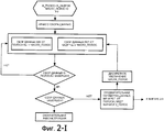
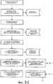
на фиг.2 в виде блок-схемы алгоритма показаны поток команд управления и поток данных, а также обработка информации, выполняемая устройством для диагностической визуализации по изобретению, иfigure 2 in the form of a flowchart of the algorithm shows the flow of control commands and data stream, as well as information processing performed by the device for diagnostic imaging according to the invention, and
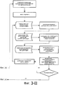
на фиг.3 в виде блок-схемы алгоритма показана обработка данных для коррекции движения данных распада при ядерном излучении (данные PET) с использованием собранных одновременно магнитно-резонансных сигналов (данных MRI) по изобретению.figure 3 in the form of a flowchart of the algorithm shows data processing for correcting the movement of decay data during nuclear radiation (PET data) using simultaneously collected magnetic resonance signals (MRI data) according to the invention.
ПОДРОБНОЕ ОПИСАНИЕ ВАРИАНТОВ ОСУЩЕСТВЛЕНИЯDETAILED DESCRIPTION OF EMBODIMENTS
На фиг.1 показано схематичное представление варианта осуществления устройства для диагностической визуализации по изобретению. Устройство для диагностической визуализации содержит систему 1 для исследований с использованием магнитного резонанса и систему 2 для эмиссионной томографии, которая по существу является PET-сканером 2. Система для исследований с использованием магнитного резонанса содержит основной магнит 11, который создает постоянное однородное основное магнитное поле в зоне 12 для исследования. Это основное магнитное поле приводит к частичной ориентации спинов в пациенте, который должен пройти обследование, вдоль силовых линий поля основного магнитного поля. Обеспечивается РЧ система 13 с одной или несколькими РЧ антеннами 63 для излучения электромагнитного поля РЧ возбуждения в зону для исследования для возбуждения спинов в теле пациента, который должен пройти обследование. Релаксирующие спины излучают магнитно-резонансные сигналы в РЧ диапазоне, которые улавливаются РЧ антеннами, выполненными, в частности, в виде приемных РЧ катушек. РЧ система выполняет функцию передачи (Тх) поля РЧ возбуждения, а также приема магнитно-резонансных сигналов. То же самое аппаратное обеспечение может быть использовано для передачи и приема. Обеспечивается Тх/Rx коммутатор 61 для переключения режимов РЧ возбуждения и приема сигнала. Кроме того, раздельные поверхностные катушки могут использоваться как локальные РЧ приемные антенны. Для передачи также могут быть использованы локальные катушки. В частности, локальная поверхностная катушка или локальная объемная катушка (т.е. Т/R катушка типа «птичьей клетки», охватывающей голову (birdcage head coil)) могут быть использованы для генерирования и приема магнитно-резонансных сигналов от соответствующего участка анатомической структуры пациента. То есть система для исследований с использованием магнитного резонанса по настоящему изобретению не требует в обязательном порядке фиксированной MR катушки, охватывающей тело (fixed MR body coil), при условии, что имеется другая катушка для возбуждения спинов и приема магнитно-резонансных сигналов. Система 62 РЧ усилителя сопряжена с Тх/Rx коммутатором 61 и выполняет функцию подачи РЧ колебаний на РЧ антенну 63. Кроме того, обеспечены градиентные катушки 14 для генерирования временных градиентных магнитных полей, в частности градиентных импульсов считывания и градиентов фазового кодирования. Обычно эти градиентные поля ориентированы во взаимно ортогональных направлениях и осуществляют пространственное кодирование магнитно-резонансных сигналов. Обеспечены градиентные усилители 71 для активации градиентных катушек 72 для генерации магнитных полей с градиентным кодированием. Градиентные усилители 71 совместно с градиентными катушками 72 образуют градиентную систему 14. Магнитно-резонансные сигналы, принятые РЧ приемными антеннами, передаются в систему сбора данных MRI (MRI-DAS), которая включает в себя спектрометр.Figure 1 shows a schematic representation of an embodiment of a device for diagnostic imaging according to the invention. The diagnostic imaging device comprises a magnetic resonance imaging research system 1 and emission tomography system 2, which is essentially a PET scanner 2. The magnetic resonance imaging research system contains a main magnet 11, which generates a constant uniform main magnetic field in the region 12 for research. This main magnetic field leads to a partial orientation of the spins in the patient to be examined along the field lines of the main magnetic field. An RF system 13 is provided with one or more RF antennas 63 for emitting an electromagnetic field of RF excitation into the study area to excite spins in the body of the patient to be examined. Relaxing spins emit magnetic resonance signals in the RF range, which are captured by RF antennas, made in particular in the form of receiving RF coils. The RF system performs the function of transmitting (Tx) the field of the RF excitation, as well as receiving magnetic resonance signals. The same hardware can be used for transmission and reception. A TX / Rx switch 61 is provided for switching RF excitation and signal reception modes. In addition, separate surface coils can be used as local RF receive antennas. Local coils can also be used for transmission. In particular, a local surface coil or a local volume coil (i.e. a T / R coil of a birdcage head coil type) can be used to generate and receive magnetic resonance signals from the corresponding portion of the patient's anatomical structure . That is, the magnetic resonance research system of the present invention does not necessarily require a fixed MR body coil, provided that there is another coil for exciting spins and receiving magnetic resonance signals. The RF amplifier system 62 is coupled to a Tx / Rx switch 61 and performs the function of supplying RF oscillations to the RF antenna 63. In addition, gradient coils 14 are provided for generating temporary gradient magnetic fields, in particular gradient read pulses and phase coding gradients. Typically, these gradient fields are oriented in mutually orthogonal directions and perform spatial coding of magnetic resonance signals. Gradient amplifiers 71 are provided for activating gradient coils 72 for generating magnetic fields with gradient coding. The gradient amplifiers 71, together with the gradient coils 72, form the
Система для эмиссионной томографии, в нашем примере система 2 PET-сканирования, содержит кольцо детекторов PET, которое расположено вокруг зоны для исследования для приема сигналов ядерного распада от пациента, который должен пройти обследование. В частности, кольцо детекторов PET и РЧ антенны выполнены с возможностью быть «чувствительными» к одному и тому же представляющему интерес объему для исследования и, например, располагаются вокруг одного и того же представляющего интерес объема для исследования. В частности, центр кольца детекторов PET совпадает с центром зоны 12 для исследования. Кольцо детекторов PET в значительной мере интегрировано с РЧ катушкой 63. Например, PET-детектор имеет детекторные элементы, чувствительные к гамма-излучению, которые вложены между проводящими стержнями (rods) РЧ катушки. Например, РЧ катушка 63 выполнена из тонких пластин, которые размещены между детекторными элементами PET-детектора. Детекторные элементы образованы отдельными детекторными кристаллами. Таким образом, проводящие стержни РЧ катушки обеспечивают механическую опору для детекторных элементов PET. С другой стороны, PET-детекторы вряд ли препятствуют работе РЧ катушки и наоборот. Кольцо 21 детекторов PET, интегрированное с РЧ катушкой, располагается перед градиентными катушками, если смотреть из зоны для исследования. То есть PET-детектор с РЧ катушкой располагается ближе к пациенту, который должен пройти обследование, чем градиентные катушки. Этим достигается то, что соответствующие пространственные области, в которых кольцо 21 детекторов РЕТ и РЧ антенны (катушка) обладают высокой чувствительностью, находятся в зоне 12 для исследования. Поскольку детекторные кристаллы не обладают существенной электрической проводимостью, они могут работать в пределах градиентной катушки при отрицательном влиянии градиентного поля. Кроме того, детекторная электроника, выполненная на полупроводниковых компонентах, смонтирована так, чтобы минимизировать вихревые токи, индуцируемые работой градиентной катушки. Сигналы ядерного распада, полученные кольцом детекторов PET, преобразуются в электронные сигналы распада (данные PET), которые направляются в систему 22 сбора данных PET. Система сбора данных PET собирает данные PET непосредственно в так называемые синограммы. The emission tomography system, in our example, the PET scanning system 2, comprises a PET detector ring that is located around the examination area to receive nuclear decay signals from the patient to be examined. In particular, the ring of PET detectors and RF antennas are configured to be “sensitive” to the same volume of interest to be studied and, for example, are arranged around the same volume of interest to be examined. In particular, the center of the ring of the PET detectors coincides with the center of the zone 12 for research. The ring of PET detectors is largely integrated with the RF coil 63. For example, the PET detector has gamma-sensitive detector elements that are embedded between the conductive rods of the RF coil. For example, the RF coil 63 is made of thin plates that are placed between the detector elements of the PET detector. Detector elements are formed by separate detector crystals. Thus, the conductive rods of the RF coils provide mechanical support for the PET detector elements. On the other hand, PET detectors are unlikely to interfere with the operation of the RF coil and vice versa. A ring of 21 PET detectors integrated with an RF coil is located in front of the gradient coils as viewed from the study area. That is, a PET detector with an RF coil is located closer to the patient to be examined than gradient coils. This ensures that the corresponding spatial areas in which the ring 21 of the PET detectors and the RF antenna (coil) are highly sensitive are in the zone 12 for research. Since the detector crystals do not have significant electrical conductivity, they can operate within the gradient coil under the negative influence of the gradient field. In addition, detector electronics made on semiconductor components are mounted so as to minimize the eddy currents induced by the operation of the gradient coil. The nuclear decay signals received by the PET detector ring are converted to electronic decay signals (PET data), which are sent to the PET data acquisition system 22. The PET data acquisition system collects PET data directly into so-called synograms.
Отдельные пары детекторов имеют отношение к соответствующей «линии ответа» (line-of-response), которая соединяет отдельные детекторы рассматриваемой пары. Линия ответа определяется своим углом ориентации и кратчайшим расстоянием между линией ответа и центром кольца детекторов PET. Для отдельного события совпадения образуется множество линий ответа и происходит сбор информации об их углах и ориентации, которая, будучи представленной в графическом виде, приводит к синусоидальной кривой для рассматриваемого совпадения (отсюда термин «синограмма»). Из угла ориентации и кратчайшего расстояния (между линией ответа и центром кольца детекторов PET) синограммы события совпадения можно определить его местоположение. Для нескольких событий совпадения осуществляется сбор информации об углах и ориентациях соответствующих линий ответа в виде пикселей в синограмме таким образом, чтобы в итоге отдельный пиксель в синограмме представлял число событий совпадения, связанных с их линией ответа, или, что то же самое, направлений пары (противоположных) детекторов. Из конечной синограммы может быть реконструировано изображение, например, с использованием фильтрованных обратных проекций. Для реконструкции PET-изображений из данных PET, в особенности синограммы, а также для реконструкции магнитно-резонансного изображения из магнитно-резонансных сигналов обеспечено устройство 5 для реконструкции изображения. Обычно устройство 5 для реконструкции изображения реализуется в программном обеспечении.Separate detector pairs are related to the corresponding line-of-response, which connects the individual detectors of the pair in question. The response line is determined by its orientation angle and the shortest distance between the response line and the center of the ring of PET detectors. For a single coincidence event, many response lines are formed and information on their angles and orientation is collected, which, when presented in graphical form, leads to a sinusoidal curve for the coincidence in question (hence the term “synogram”). From the orientation angle and the shortest distance (between the response line and the center of the ring of PET detectors), the synogram of the coincidence event can determine its location. For several coincidence events, information is collected on the angles and orientations of the corresponding response lines in the form of pixels in the synogram so that as a result a single pixel in the synogram represents the number of coincidence events associated with their response line, or, which is the same, the directions of the pair ( opposite) detectors. An image can be reconstructed from a final synogram, for example, using filtered back projections. For reconstructing PET images from PET data, in particular a synogram, and also for reconstructing a magnetic resonance image from magnetic resonance signals, a device 5 for reconstructing an image is provided. Typically, the device 5 for image reconstruction is implemented in software.
Система для исследований с использованием магнитного резонанса возбуждает спины в объекте, который должен быть обследован и помещен в зону для исследования, путем приложения поля РЧ возбуждения с использованием РЧ антенны, в частности РЧ катушки 63. РЧ катушка активируется РЧ усилителем 62 при работе Тх/Rx коммутатора в режиме передачи. Благодаря РЧ возбуждению релаксация возбужденных спинов приводит к появлению магнитно-резонансных сигналов от объекта. Магнитно-резонансные сигналы принимаются РЧ катушкой и подаются в магнитно-резонансный томограф для сканирования k-пространства для сбора данных по магнитно-резонансным сигналам. Путем приложения кодирующих градиентов происходит сканирование k-пространства, а полученные данные MRI подаются в MRI-DAS 64 и, в конечном счете, в устройство 5 для реконструкции изображения. Главный компьютер 3 управляет РЧ системой 13 и градиентной системой 14 так, чтобы осуществить приемлемую последовательность сбора данных для сканирования k-пространства для сбора магнитно-резонансных сигналов. В частности, система для исследований с использованием магнитного резонанса выполняет последовательность сбора данных типа PROPELLER, при которой осуществляется сканирование центральной области k-пространства с резервированием. Такое избыточное сканирование предполагает, что одна и та же центральная область k-пространства просматривается последовательно несколько раз. Если движение не происходит, то последовательные наблюдения дадут по существу одинаковый результат. Соответственно изменения в результатах наблюдения центральной области k-пространства представляют изменения, вызванные, например, движением, которое имело место в процессе последовательных просмотров. В частности, для каждой полосы, отсканированной в k-пространстве, оцениваются параметры коррекции движения. Эти параметры главным образом касаются использования весовых коэффициентов для вращения, параллельного переноса и перемещения «сквозь» плоскость. Могут также быть использованы другие последовательности сбора данных, при которых осуществляется просмотр с резервированием центральной области k-пространства. Частными примерами последовательностей сбора данных, которые удовлетворительно работают для достижения избыточности в центральной области k-пространства, являются 3D-TRICKS, которые предполагают периодическое повторное сканирование центральной области k-пространства; хорошие результаты также достигнуты с использованием 4D-TRACKS, где предполагается начинать сканирования из положения вне центральной области k-пространства для сбора сигналов с максимальным контрастным усилением из центральной области k-пространства, и где используются неодинаковые подходы к сбору данных в центральной области и периферийной области k-пространства соответственно. Кроме того, эти последовательности сбора данных могут быть объединены с аналогичными технологиями визуализации.A magnetic resonance research system excites spins in an object to be examined and placed in a study area by applying an RF excitation field using an RF antenna, in particular an RF coil 63. The RF coil is activated by an RF amplifier 62 during Tx / Rx operation switch in transmission mode. Due to RF excitation, the relaxation of excited spins leads to the appearance of magnetic resonance signals from the object. Magnetic resonance signals are received by the RF coil and fed to a magnetic resonance imager to scan the k-space to collect data on magnetic resonance signals. By applying coding gradients, k-space is scanned, and the obtained MRI data is supplied to the MRI-DAS 64 and, ultimately, to the image reconstruction apparatus 5. The
Собранные данные PET и MRI имеют «временную метку» («time-stamped») и содержатся в кадрах, соответствующих времени, необходимому для сбора магнитно-резонансных сигналов от индивидуальной полосы в k-пространстве. Магнитно-резонансные сигналы могут быть собраны одновременно со сбором данных PET. Затем для индивидуальных синограмм PET осуществляют сбор соответствующих полос в k-пространстве. Когда осуществляют сбор данных о следующей полосе, вращающейся в k-пространстве магнитно-резонансных сигналов, одновременно собранные данные PET сохраняют в виде нового кадра, связанного с только что вращавшейся полосой в k-пространстве.The PET and MRI data collected are “time-stamped” and are contained in frames corresponding to the time required to collect the magnetic resonance signals from an individual band in k-space. Magnetic resonance signals can be collected simultaneously with the collection of PET data. Then, for individual PET synograms, the corresponding bands are collected in k-space. When data is collected on the next band rotating in the k-space of the magnetic resonance signals, the simultaneously collected PET data is saved as a new frame associated with the just-spinning band in the k-space.
В состав главного компьютера входит аналитический блок 4, в частности в виде модуля программного обеспечения. Аналитический блок 4 рассчитывает требуемую коррекцию движения из отобранных данных из избыточно отсканированной центральной области k-пространства. Коррекция движения, полученная из магнитно-резонансных сигналов, прилагается к одновременно собранным данным PET. В частности, проходят обработку индивидуальные синограммы PET, т.е. реконструируются в индивидуальные кадры изображения PET, которые затем корректируются с учетом движения. Коррекции движения могут применяться для индивидуальных синограмм перед проекционной реконструкцией. Требуемые коррекции транслируются из пространственной области в пространство синограммы. Далее кадры изображения PET с коррекцией движения реконструируются (например, взвешенным суммированием) в изображения PET с коррекцией движения. По альтернативному варианту, коррекция движения может применяться к индивидуальным кадрам изображения PET, которые включают в себя вращения и искажения геометрии кадра изображения. Кроме того, коррекции движения «сквозь» плоскость могут также включать в себя взвешивание индивидуального кадра изображения PET на основе попиксельной схемы.The main computer includes an analytical unit 4, in particular in the form of a software module. The analytical unit 4 calculates the required motion correction from the selected data from the excessively scanned central region of k-space. Motion correction obtained from magnetic resonance signals is attached to the simultaneously collected PET data. In particular, individual PET synograms, i.e. reconstructed into individual PET image frames, which are then adjusted for motion. Motion corrections can be applied to individual synograms before projection reconstruction. The required corrections are translated from the spatial domain to the synogram space. Further, motion correction PET image frames are reconstructed (for example, by weighted summation) into motion correction PET images. Alternatively, motion correction can be applied to individual PET image frames, which include rotations and distortions in the geometry of the image frame. In addition, “through” plane motion corrections may also include weighting an individual PET image frame based on a pixel-by-pixel circuit.
На фиг.2 показана блок-схема алгоритма одновременного сбора и предварительной обработки магнитно-резонансных сигналов (данных MRI) и сигналов ядерного распада (данных PET). Данные MRI собраны в таком виде, который делает их адекватными для коррекции движения как данных MRI, так и данных PET, а также изображений, реконструированных из этих собранных данных.Figure 2 shows a block diagram of an algorithm for the simultaneous collection and pre-processing of magnetic resonance signals (MRI data) and nuclear decay signals (PET data). MRI data are collected in a form that makes them adequate for correcting the movement of both MRI data and PET data, as well as images reconstructed from these collected data.
На фиг.3 показана блок-схема алгоритма реконструкции, которая следует за окончанием сбора всех данных (MRI и PET), которые используются для реконструкции магнитно-резонансного изображения с компенсацией движения, а также эмиссионного томографического изображения (изображения PET) с компенсацией движения.Figure 3 shows a block diagram of the reconstruction algorithm, which follows the end of the collection of all data (MRI and PET), which are used to reconstruct the magnetic resonance image with motion compensation, as well as the emission tomographic image (PET image) with motion compensation.
Claims (7)
- систему (1) для исследований с использованием магнитного резонанса для сбора магнитно-резонансных сигналов
- систему (2) для эмиссионной томографии для сбора сигналов ядерного распада, а также
- аналитический модуль (4) для получения коррекции (коррекций) движения из магнитно-резонансных сигналов, а также
- модуль (5) для реконструкции, предназначенный для реконструкции эмиссионного томографического изображения с коррекцией движения из сигналов ядерного распада на основе упомянутой коррекции (коррекций) движения;
- системный контроллер 3, связанный с системой для исследований с использованием магнитного резонанса и системой для эмиссионной томографии,
причем системный контроллер выполняет функции по управлению
- сбором магнитно-резонансных сигналов, системой для исследований с использованием магнитного резонанса, а также
- сбором сигналов ядерного распада, системой для эмиссионной томографии;
- системный контроллер дополнительно имеет функцию регистрации времени сбора магнитно-резонансных сигналов и сигналов ядерного распада, при этом
- магнитно-резонансные сигналы для получения коррекции движения и сигналы ядерного распада для реконструкции эмиссионного томографического изображения имеют одинаковое время сбора.1. Device for diagnostic imaging, containing
- system (1) for studies using magnetic resonance to collect magnetic resonance signals
- system (2) for emission tomography to collect nuclear decay signals, as well as
- an analytical module (4) for obtaining correction (s) of motion from magnetic resonance signals, as well as
- module (5) for reconstruction, intended for reconstruction of emission tomographic image with motion correction from nuclear decay signals based on the said motion correction (s);
- a system controller 3 associated with a system for research using magnetic resonance and a system for emission tomography,
moreover, the system controller performs management functions
- collection of magnetic resonance signals, a system for research using magnetic resonance, and
- collection of nuclear decay signals, a system for emission tomography;
- the system controller additionally has a function of recording the time of collection of magnetic resonance signals and signals of nuclear decay, while
- magnetic resonance signals to obtain motion correction and nuclear decay signals for reconstruction of emission tomographic images have the same collection time.
Applications Claiming Priority (2)
| Application Number | Priority Date | Filing Date | Title |
|---|---|---|---|
| EP06126443.8 | 2006-12-19 | ||
| EP06126443 | 2006-12-19 |
Publications (2)
| Publication Number | Publication Date |
|---|---|
| RU2009127729A RU2009127729A (en) | 2011-01-27 |
| RU2457503C2 true RU2457503C2 (en) | 2012-07-27 |
Family
ID=39319611
Family Applications (1)
| Application Number | Title | Priority Date | Filing Date |
|---|---|---|---|
| RU2009127729/28A RU2457503C2 (en) | 2006-12-19 | 2007-12-13 | Motion correction in positron emission/magnetic resonance hybrid imaging system |
Country Status (7)
| Country | Link |
|---|---|
| US (1) | US8938280B2 (en) |
| EP (1) | EP2095147A1 (en) |
| JP (2) | JP2010512907A (en) |
| CN (1) | CN101563624B (en) |
| BR (1) | BRPI0720535A2 (en) |
| RU (1) | RU2457503C2 (en) |
| WO (1) | WO2008075265A1 (en) |
Families Citing this family (22)
| Publication number | Priority date | Publication date | Assignee | Title |
|---|---|---|---|---|
| DE102006054542B4 (en) * | 2006-11-20 | 2012-12-06 | Siemens Ag | Device for overlaid MRI and PET imaging |
| US20110066026A1 (en) * | 2009-04-21 | 2011-03-17 | The Regents Of The University Of California | Rf coil for use in magnetic resonance imaging in integrated spect and mr imaging |
| US20110270078A1 (en) * | 2010-04-30 | 2011-11-03 | Wagenaar Douglas J | Methods and systems of combining magnetic resonance and nuclear imaging |
| JP5713468B2 (en) * | 2010-10-25 | 2015-05-07 | 独立行政法人放射線医学総合研究所 | PET / MRI integrated device |
| US20120169341A1 (en) * | 2010-12-29 | 2012-07-05 | General Electric Company | Integrated gamma ray detector ring and rf body coil |
| DE102011007871B4 (en) * | 2011-04-21 | 2017-07-27 | Siemens Healthcare Gmbh | Method for acquiring MR image data and corresponding combined MR / ET device |
| US9591989B2 (en) * | 2011-04-22 | 2017-03-14 | Washington University | Insert device for enhancing PET and MRI images |
| EP2812717B1 (en) | 2012-02-09 | 2022-04-06 | Koninklijke Philips N.V. | Data detection device for use in combination with an mri apparatus |
| US9392958B2 (en) * | 2012-05-30 | 2016-07-19 | Siemens Aktiengesellschaft | Method of attenuation correction of positron emission tomography data and combined positron emission tomography and magnetic resonance tomography system |
| RU2015107841A (en) | 2012-08-08 | 2016-09-27 | Конинклейке Филипс Н.В. | MULTI-FRAME MAGNETIC RESONANT VISUALIZATION WITH SUSTAINABLE CORRECTION OF TWO IMAGES |
| DE102012218289A1 (en) * | 2012-10-08 | 2014-04-10 | Siemens Aktiengesellschaft | Method for generating movement-corrected PET image of examination region in combined MR PET system, involves determining movement-corrected PET image from PET events by using calculated movement information |
| KR101461099B1 (en) * | 2012-11-09 | 2014-11-13 | 삼성전자주식회사 | Magnetic resonance imaging apparatus and acquiring method of functional magnetic resonance image using the same |
| DE102013205278A1 (en) | 2013-03-26 | 2014-10-02 | Siemens Aktiengesellschaft | Method for displaying signal values of a combined magnetic resonance positron emission tomography device and correspondingly designed magnetic resonance positron emission tomography device |
| DE102013205576A1 (en) * | 2013-03-28 | 2014-10-02 | Friedrich-Alexander-Universität Erlangen-Nürnberg | Method for generating a movement correction for PET data, method for generating PET images as well as correspondingly configured MR system and PET system |
| DE102013208620A1 (en) * | 2013-05-10 | 2014-11-13 | Siemens Aktiengesellschaft | A medical imaging system comprising a magnetic resonance imaging unit and a positron emission tomography unit |
| US9730664B2 (en) * | 2014-04-14 | 2017-08-15 | Siemens Medical Solutions Usa, Inc. | Multi-bed elastic motion correction |
| CN104020430B (en) * | 2014-04-15 | 2017-01-25 | 清华大学 | Correction method and system for movement artifacts of magnetic resonance imaging |
| DE102014221634A1 (en) * | 2014-10-24 | 2016-04-28 | Siemens Aktiengesellschaft | Method for determining a radiation dose of a radiopharmaceutical |
| CN107481226B (en) * | 2017-07-27 | 2021-06-01 | 东软医疗系统股份有限公司 | Method and device for removing abnormal scanning data and PET system |
| US11426131B2 (en) * | 2018-12-17 | 2022-08-30 | Siemens Medical Solutions Usa, Inc. | Automated motion correction in PET imaging |
| US11300695B2 (en) | 2020-04-24 | 2022-04-12 | Ronald Nutt | Time-resolved positron emission tomography encoder system for producing event-by-event, real-time, high resolution, three-dimensional positron emission tomographic image without the necessity of performing image reconstruction |
| US11054534B1 (en) | 2020-04-24 | 2021-07-06 | Ronald Nutt | Time-resolved positron emission tomography encoder system for producing real-time, high resolution, three dimensional positron emission tomographic image without the necessity of performing image reconstruction |
Citations (1)
| Publication number | Priority date | Publication date | Assignee | Title |
|---|---|---|---|---|
| RU2171630C2 (en) * | 1999-06-18 | 2001-08-10 | Пестряков Андрей Витальевич | Method for matching of three-dimensional images obtained with the aid of computer tomographs operating on the basis of various physical principles |
Family Cites Families (49)
| Publication number | Priority date | Publication date | Assignee | Title |
|---|---|---|---|---|
| US4939464A (en) * | 1989-07-11 | 1990-07-03 | Intermagnetics General Corporation | NMR-PET scanner apparatus |
| US5251128A (en) * | 1990-11-19 | 1993-10-05 | General Electric Company | Motion artifact reduction in projection imaging |
| US5200700A (en) * | 1990-11-30 | 1993-04-06 | General Electric | Reduction of NMR artifacts caused by time varying linear geometric distortion |
| JP3325300B2 (en) | 1992-02-28 | 2002-09-17 | 株式会社東芝 | Ultrasound therapy equipment |
| US5247935A (en) * | 1992-03-19 | 1993-09-28 | General Electric Company | Magnetic resonance guided focussed ultrasound surgery |
| US6088611A (en) * | 1995-08-18 | 2000-07-11 | The Board Of Trustees Of The University Of Illinois | Model based method for high resolution dynamic imaging |
| DE69840444D1 (en) * | 1997-05-23 | 2009-02-26 | Prorhythm Inc | DISMISSABLE FOCUSING ULTRASOUND APPLICATOR OF HIGH INTENSITY |
| US7239908B1 (en) * | 1998-09-14 | 2007-07-03 | The Board Of Trustees Of The Leland Stanford Junior University | Assessing the condition of a joint and devising treatment |
| US6377833B1 (en) * | 1999-01-25 | 2002-04-23 | Douglas Albert | System and method for computer input of dynamic mental information |
| US6490476B1 (en) * | 1999-10-14 | 2002-12-03 | Cti Pet Systems, Inc. | Combined PET and X-ray CT tomograph and method for using same |
| JP2002165774A (en) | 2000-12-01 | 2002-06-11 | Hitachi Medical Corp | Magnetic resonance imaging device |
| US6946841B2 (en) * | 2001-08-17 | 2005-09-20 | Igor Rubashov | Apparatus for combined nuclear imaging and magnetic resonance imaging, and method thereof |
| DE10162768A1 (en) * | 2001-12-20 | 2003-07-03 | Philips Intellectual Property | CT Scanner |
| US6892090B2 (en) * | 2002-08-19 | 2005-05-10 | Surgical Navigation Technologies, Inc. | Method and apparatus for virtual endoscopy |
| JP2006519051A (en) * | 2003-02-28 | 2006-08-24 | コーニンクレッカ フィリップス エレクトロニクス エヌ ヴィ | Movable table MRI using sub-sampling |
| US7450983B2 (en) * | 2003-03-18 | 2008-11-11 | University Of Cincinnati | Automated brain MRI and CT prescriptions in Talairach space |
| JP3929047B2 (en) * | 2003-04-24 | 2007-06-13 | 株式会社日立メディコ | Magnetic resonance imaging system |
| CN1809841B (en) * | 2003-06-18 | 2010-05-12 | 皇家飞利浦电子股份有限公司 | Motion compensated reconstruction method, equipment and system |
| FR2860630B1 (en) * | 2003-10-01 | 2006-04-28 | Commissariat Energie Atomique | METHOD FOR IMAGE RECONSTRUCTION WITH DATA ACQUISITION BY MULTIPLE MODES OF IMAGING AND SYNCHRONIZATION OF IMAGE SERIES. |
| US7286867B2 (en) * | 2003-10-16 | 2007-10-23 | Brookhaven Science Associates, Llc | Combined PET/MRI scanner |
| JP4514438B2 (en) * | 2003-11-28 | 2010-07-28 | 株式会社日立メディコ | Treatment device control system |
| JP4012177B2 (en) | 2004-07-09 | 2007-11-21 | 株式会社東芝 | Ultrasonic therapy device |
| US7937131B2 (en) * | 2004-09-06 | 2011-05-03 | Gachon University Of Medicine & Science Industry-Academic Cooperation Foundation | PET—MRI hybrid apparatus and method of implementing the same |
| US7787935B2 (en) * | 2004-09-27 | 2010-08-31 | General Electric Company | System and method for correcting motion artifacts in imaging |
| US8989349B2 (en) * | 2004-09-30 | 2015-03-24 | Accuray, Inc. | Dynamic tracking of moving targets |
| US7627370B2 (en) * | 2004-10-20 | 2009-12-01 | Marks Donald H | Brain function decoding process and system |
| CN100493450C (en) | 2004-11-12 | 2009-06-03 | 株式会社东芝 | Magnetic resonance imaging apparatus, image data correction apparatus, and image data correction method |
| CN1644162A (en) | 2005-01-17 | 2005-07-27 | 天津医科大学总医院 | Three dimensionally orientated cardiac PCT-CT and MR1 image imersing diagnosis and apparatus |
| DE102005015070B4 (en) * | 2005-04-01 | 2017-02-02 | Siemens Healthcare Gmbh | Combined positron emission tomography and magnetic resonance tomography device |
| DE102005015071B4 (en) * | 2005-04-01 | 2008-06-19 | Siemens Ag | Combined positron emission tomography and magnetic resonance tomography device |
| US7218112B2 (en) * | 2005-05-12 | 2007-05-15 | Siemens Aktiengesellschaft | Combined MR/PET system |
| DE102005023907A1 (en) * | 2005-05-24 | 2006-12-07 | Siemens Ag | Method for determining positron emission measurement information in the context of positron emission tomography |
| CN2815414Y (en) | 2005-08-13 | 2006-09-13 | 宋世鹏 | Radioactive therapentic apparatus |
| DE102006052437B4 (en) * | 2006-11-07 | 2011-04-21 | Siemens Ag | Magnetic resonance system with components |
| DE102006054542B4 (en) * | 2006-11-20 | 2012-12-06 | Siemens Ag | Device for overlaid MRI and PET imaging |
| US20080146914A1 (en) * | 2006-12-19 | 2008-06-19 | General Electric Company | System, method and apparatus for cancer imaging |
| US7667457B2 (en) * | 2006-12-22 | 2010-02-23 | General Electric Co. | System and apparatus for detecting gamma rays in a PET/MRI scanner |
| GB0709560D0 (en) * | 2007-05-18 | 2007-06-27 | Siemens Medical Solutions | Motion compensation in PET reconstruction |
| US9535145B2 (en) * | 2007-11-09 | 2017-01-03 | Koninklijke Philips N.V. | MR-PET cyclic motion gating and correction |
| DE102009023806B4 (en) * | 2008-07-09 | 2011-04-28 | Siemens Aktiengesellschaft | Combined PET-MR device, component and local coil |
| KR101031483B1 (en) * | 2009-02-24 | 2011-04-26 | 성균관대학교산학협력단 | Pet-mri combined system |
| US20130131493A1 (en) * | 2011-11-22 | 2013-05-23 | General Electric Company | Method and apparatus for performing dual-modality imaging |
| DE102009048302B4 (en) * | 2009-10-05 | 2011-07-07 | Siemens Aktiengesellschaft, 80333 | Correction of truncations in MR imaging |
| DE102010033610B4 (en) * | 2010-08-06 | 2020-09-10 | Siemens Healthcare Gmbh | Method for displaying a lymph node and a correspondingly designed combined MR / PET device |
| US20120169341A1 (en) * | 2010-12-29 | 2012-07-05 | General Electric Company | Integrated gamma ray detector ring and rf body coil |
| DE102011007871B4 (en) * | 2011-04-21 | 2017-07-27 | Siemens Healthcare Gmbh | Method for acquiring MR image data and corresponding combined MR / ET device |
| US8797030B2 (en) * | 2011-07-28 | 2014-08-05 | General Electric Company | Magnetic resonance radio-frequency coil and method of manufacturing |
| US8923592B2 (en) * | 2012-05-29 | 2014-12-30 | General Electric Company | Methods and systems for performing attenuation correction |
| US9392958B2 (en) * | 2012-05-30 | 2016-07-19 | Siemens Aktiengesellschaft | Method of attenuation correction of positron emission tomography data and combined positron emission tomography and magnetic resonance tomography system |
-
2007
- 2007-12-13 US US12/519,863 patent/US8938280B2/en not_active Expired - Fee Related
- 2007-12-13 WO PCT/IB2007/055080 patent/WO2008075265A1/en active Application Filing
- 2007-12-13 BR BRPI0720535-0A patent/BRPI0720535A2/en not_active Application Discontinuation
- 2007-12-13 JP JP2009542308A patent/JP2010512907A/en active Pending
- 2007-12-13 EP EP07859376A patent/EP2095147A1/en not_active Ceased
- 2007-12-13 CN CN200780046870.0A patent/CN101563624B/en not_active Expired - Fee Related
- 2007-12-13 RU RU2009127729/28A patent/RU2457503C2/en not_active IP Right Cessation
-
2014
- 2014-10-14 JP JP2014209583A patent/JP5997230B2/en not_active Expired - Fee Related
Patent Citations (1)
| Publication number | Priority date | Publication date | Assignee | Title |
|---|---|---|---|---|
| RU2171630C2 (en) * | 1999-06-18 | 2001-08-10 | Пестряков Андрей Витальевич | Method for matching of three-dimensional images obtained with the aid of computer tomographs operating on the basis of various physical principles |
Non-Patent Citations (1)
| Title |
|---|
| Lucas A.J., Hawkes R.C., Ansorge R.E., Williams G.B., Nutt R.E., Clark J.C., Fryer T.A., Carpenter T.A. Development of a Combined microPET-MR System, TECHNOLOGY IN CANCER RESEARCH AND TREATMENT, 01.08.2006, ADENINE PRESS, SCHENECTADY, NY, US, часть 5, №4, стр.337-341. SCHWAIGER M. et al., MR-PET: Combining Function, Anatomy, and More, MEDICAL SOLUTIONS, SPECIAL EDITION, MOLECULAR IMAGING, 01.01.2005, Siemens medical, с.25-30. * |
Also Published As
| Publication number | Publication date |
|---|---|
| BRPI0720535A2 (en) | 2014-01-07 |
| RU2009127729A (en) | 2011-01-27 |
| WO2008075265A1 (en) | 2008-06-26 |
| JP2010512907A (en) | 2010-04-30 |
| JP2015042986A (en) | 2015-03-05 |
| CN101563624B (en) | 2013-08-21 |
| EP2095147A1 (en) | 2009-09-02 |
| US8938280B2 (en) | 2015-01-20 |
| US20100106004A1 (en) | 2010-04-29 |
| CN101563624A (en) | 2009-10-21 |
| JP5997230B2 (en) | 2016-09-28 |
Similar Documents
| Publication | Publication Date | Title |
|---|---|---|
| RU2457503C2 (en) | Motion correction in positron emission/magnetic resonance hybrid imaging system | |
| Pichler et al. | Multimodal imaging approaches: pet/ct and pet/mri | |
| EP2424429B1 (en) | Imaging device for three dimensional anatomical and functional imaging and methods thereof | |
| CN102908144B (en) | Magnetic resonance imaging for treatment plan | |
| US8861819B2 (en) | Apparatus and method for correcting artifacts of functional image acquired by magnetic resonance imaging | |
| US10288702B2 (en) | System for simultaneous PET/MR imaging | |
| JP6324308B2 (en) | Motion-triggered MR imaging using APT / CEST | |
| US10838030B2 (en) | Hybrid examination system having an MR scanner, an X ray source and an X ray detector | |
| US20080037851A1 (en) | Medical image synthesis method and apparatus | |
| US6973162B2 (en) | MR/X-ray scanner having rotatable anode | |
| JP3180510U (en) | System for hyperpolarizing unpolarized gas and hyperpolarized gas imaging system | |
| KR20180089711A (en) | Apparatus and method for acquiring magnetic resonance data | |
| US20160069973A1 (en) | Combined magnetic resonance-emission tomography device, and method for imaging an examination object therewith | |
| CN112798995A (en) | Motion monitoring method applied to magnetic resonance imaging and magnetic resonance imaging system | |
| CN212779131U (en) | Depth data measuring apparatus | |
| JP4576534B2 (en) | Magnetic resonance imaging apparatus and imaging method | |
| Dong et al. | Rectification of distortion in MRI for stereotaxy | |
| Bottomley et al. | Head and body imaging by hydrogen nuclear magnetic resonance | |
| Maramraju et al. | An MR compatible PET scanner based on RatCAP for small animal imaging at 9.4 T | |
| JPS62167554A (en) | Nmr imaging apparatus | |
| Huber | Scanning Technologies | |
| WO2001033244A1 (en) | An integrated low field mri/rf epri for co-registering imaging of in vivo physiology and anatomy in living objects | |
| Dumoulin et al. | Moving table imaging at 1.5 and 3.0 Tesla | |
| Ballon et al. | Rapid three-dimensional whole-body diffusion-weighted echo planar magnetic resonance imaging of metastatic neoplasia | |
| Erlichman | Surface/Specialty Coil Devices and Gating Techniques in Magnetic Resonance Imaging Health Technology Assessment Reports, 1990 Number 3 |
Legal Events
| Date | Code | Title | Description |
|---|---|---|---|
| MM4A | The patent is invalid due to non-payment of fees |
Effective date: 20181214 |