RU2419400C2 - Light-conducting infusion cannula - Google Patents
Light-conducting infusion cannula Download PDFInfo
- Publication number
- RU2419400C2 RU2419400C2 RU2008129030/14A RU2008129030A RU2419400C2 RU 2419400 C2 RU2419400 C2 RU 2419400C2 RU 2008129030/14 A RU2008129030/14 A RU 2008129030/14A RU 2008129030 A RU2008129030 A RU 2008129030A RU 2419400 C2 RU2419400 C2 RU 2419400C2
- Authority
- RU
- Russia
- Prior art keywords
- cannula
- transparent
- optical fiber
- light
- illuminator
- Prior art date
Links
Images


Classifications
-
- A—HUMAN NECESSITIES
- A61—MEDICAL OR VETERINARY SCIENCE; HYGIENE
- A61F—FILTERS IMPLANTABLE INTO BLOOD VESSELS; PROSTHESES; DEVICES PROVIDING PATENCY TO, OR PREVENTING COLLAPSING OF, TUBULAR STRUCTURES OF THE BODY, e.g. STENTS; ORTHOPAEDIC, NURSING OR CONTRACEPTIVE DEVICES; FOMENTATION; TREATMENT OR PROTECTION OF EYES OR EARS; BANDAGES, DRESSINGS OR ABSORBENT PADS; FIRST-AID KITS
- A61F9/00—Methods or devices for treatment of the eyes; Devices for putting-in contact lenses; Devices to correct squinting; Apparatus to guide the blind; Protective devices for the eyes, carried on the body or in the hand
- A61F9/007—Methods or devices for eye surgery
- A61F9/00736—Instruments for removal of intra-ocular material or intra-ocular injection, e.g. cataract instruments
-
- A—HUMAN NECESSITIES
- A61—MEDICAL OR VETERINARY SCIENCE; HYGIENE
- A61B—DIAGNOSIS; SURGERY; IDENTIFICATION
- A61B17/00—Surgical instruments, devices or methods, e.g. tourniquets
- A61B17/34—Trocars; Puncturing needles
- A61B17/3417—Details of tips or shafts, e.g. grooves, expandable, bendable; Multiple coaxial sliding cannulas, e.g. for dilating
- A61B17/3421—Cannulas
-
- A—HUMAN NECESSITIES
- A61—MEDICAL OR VETERINARY SCIENCE; HYGIENE
- A61B—DIAGNOSIS; SURGERY; IDENTIFICATION
- A61B17/00—Surgical instruments, devices or methods, e.g. tourniquets
- A61B17/34—Trocars; Puncturing needles
- A61B17/3417—Details of tips or shafts, e.g. grooves, expandable, bendable; Multiple coaxial sliding cannulas, e.g. for dilating
- A61B2017/3419—Sealing means between cannula and body
-
- A—HUMAN NECESSITIES
- A61—MEDICAL OR VETERINARY SCIENCE; HYGIENE
- A61B—DIAGNOSIS; SURGERY; IDENTIFICATION
- A61B90/00—Instruments, implements or accessories specially adapted for surgery or diagnosis and not covered by any of the groups A61B1/00 - A61B50/00, e.g. for luxation treatment or for protecting wound edges
- A61B90/30—Devices for illuminating a surgical field, the devices having an interrelation with other surgical devices or with a surgical procedure
- A61B2090/306—Devices for illuminating a surgical field, the devices having an interrelation with other surgical devices or with a surgical procedure using optical fibres
-
- A—HUMAN NECESSITIES
- A61—MEDICAL OR VETERINARY SCIENCE; HYGIENE
- A61M—DEVICES FOR INTRODUCING MEDIA INTO, OR ONTO, THE BODY; DEVICES FOR TRANSDUCING BODY MEDIA OR FOR TAKING MEDIA FROM THE BODY; DEVICES FOR PRODUCING OR ENDING SLEEP OR STUPOR
- A61M2205/00—General characteristics of the apparatus
- A61M2205/58—Means for facilitating use, e.g. by people with impaired vision
- A61M2205/587—Lighting arrangements
-
- A—HUMAN NECESSITIES
- A61—MEDICAL OR VETERINARY SCIENCE; HYGIENE
- A61M—DEVICES FOR INTRODUCING MEDIA INTO, OR ONTO, THE BODY; DEVICES FOR TRANSDUCING BODY MEDIA OR FOR TAKING MEDIA FROM THE BODY; DEVICES FOR PRODUCING OR ENDING SLEEP OR STUPOR
- A61M2210/00—Anatomical parts of the body
- A61M2210/06—Head
- A61M2210/0612—Eyes
-
- A—HUMAN NECESSITIES
- A61—MEDICAL OR VETERINARY SCIENCE; HYGIENE
- A61M—DEVICES FOR INTRODUCING MEDIA INTO, OR ONTO, THE BODY; DEVICES FOR TRANSDUCING BODY MEDIA OR FOR TAKING MEDIA FROM THE BODY; DEVICES FOR PRODUCING OR ENDING SLEEP OR STUPOR
- A61M5/00—Devices for bringing media into the body in a subcutaneous, intra-vascular or intramuscular way; Accessories therefor, e.g. filling or cleaning devices, arm-rests
- A61M5/14—Infusion devices, e.g. infusing by gravity; Blood infusion; Accessories therefor
- A61M5/158—Needles for infusions; Accessories therefor, e.g. for inserting infusion needles, or for holding them on the body
Landscapes
- Health & Medical Sciences (AREA)
- Life Sciences & Earth Sciences (AREA)
- Surgery (AREA)
- Ophthalmology & Optometry (AREA)
- Engineering & Computer Science (AREA)
- Biomedical Technology (AREA)
- Heart & Thoracic Surgery (AREA)
- Nuclear Medicine, Radiotherapy & Molecular Imaging (AREA)
- Animal Behavior & Ethology (AREA)
- General Health & Medical Sciences (AREA)
- Public Health (AREA)
- Veterinary Medicine (AREA)
- Vascular Medicine (AREA)
- Pathology (AREA)
- Medical Informatics (AREA)
- Molecular Biology (AREA)
- Infusion, Injection, And Reservoir Apparatuses (AREA)
Abstract
Description
Родственные заявкиRelated Applications
По данной заявке испрашивается приоритет в соответствии с включенной в качестве ссылки во всей своей полноте для всех целей предварительной патентной заявкой США №60/751175, озаглавленной «Прозрачная светопроводящая инфузионная канюля», поданной 16 декабря 2005 года.This application claims priority in accordance with incorporated by reference in its entirety for all purposes, provisional patent application US No. 60/751175, entitled "Transparent light-transmitting infusion cannula", filed December 16, 2005.
Эта заявка относится и включает в себя посредством ссылки во всей своей полноте для всех целей предварительную патентную заявку США №60/653265, поданную 15 февраля 2005 года, озаглавленную «Зонд эндосветильника высокой пропускной способности».This application relates and includes by reference in its entirety for all purposes, provisional patent application US No. 60/653265, filed February 15, 2005, entitled "High-bandwidth End Light Probe".
Эта заявка относится и включает в себя посредством ссылки во всей своей полноте для всех целей непредварительную патентную заявку США №11/354615, поданную 15 февраля 2006, озаглавленную «Зонд эндосветильника высокой пропускной способности».This application relates and includes by reference in its entirety for all purposes, the non-provisional patent application US No. 11/354615, filed February 15, 2006, entitled "High-throughput Endlight Probe".
Область техники, к которой относится изобретениеFIELD OF THE INVENTION
Настоящее изобретение в целом относится к хирургическому инструментарию. Конкретно, настоящее изобретение относится к хирургическим инструментам для освещения операционной области в процессе офтальмологических операций. Еще более конкретно настоящее изобретение относится к инструменту для проведения инфузии, имеющему блок освещения для освещения внутреннего пространства глазного яблока.The present invention generally relates to surgical instruments. Specifically, the present invention relates to surgical instruments for illuminating an operating area during an ophthalmic operation. Even more specifically, the present invention relates to an infusion instrument having an illumination unit for illuminating an inner space of an eyeball.
Предшествующий уровень техники изобретенияBACKGROUND OF THE INVENTION
В офтальмологии и, в частности, в хирургии стекловидного тела и сетчатки желательно использовать широкоугольную систему операционного микроскопа, чтобы рассмотреть как можно больший участок сетчатки. Широкоугольные линзы объектива для такого рода микроскопических систем существуют, однако они требуют более широкой области освещения, чем та, которая обеспечивается конусом освещения типичного волоконно-оптического зонда. В результате были разработаны различные технологии для того, чтобы увеличить рассеивание относительно некогерентного света, осуществляемое волоконно-оптическим светильником. Эти общеизвестные широкоугольные светильники могут, таким образом, осветить больший участок сетчатки, как требуется в современных широкоугольных системах операционного микроскопа.In ophthalmology, and in particular in vitreous and retinal surgery, it is advisable to use a wide-angle system of an operating microscope in order to examine the largest possible area of the retina. Wide-angle lenses for such microscopic systems exist, but they require a wider area of illumination than that provided by the cone of illumination of a typical fiber optic probe. As a result, various technologies have been developed in order to increase the diffusion of relatively incoherent light by a fiber optic lamp. These well-known wide-angle luminaires can thus illuminate a larger portion of the retina, as is required in modern wide-angle systems of the operating microscope.
Также является общеизвестным размещение оптических волокон внутри рабочего конца хирургического инструмента. Это избавляет от необходимости иметь отдельный порт освещения и дает преимущество, заключающееся в направлении светового пучка вместе с инструментом на целевой участок. При этом размеры инструмента должны быть соответственно увеличены, и могут быть необходимы более масштабные склеротомии. Альтернативная операция заключается в использовании светопроводящей инфузионной канюли для объединения инфузионной и осветительной функции в единственной точке.It is also well known to place optical fibers inside the working end of a surgical instrument. This eliminates the need to have a separate lighting port and gives the advantage of directing the light beam along with the instrument to the target area. In this case, the dimensions of the instrument should be accordingly increased, and larger sclerotomy may be necessary. An alternative operation is to use a light guide infusion cannula to combine the infusion and lighting functions at a single point.
Один из примеров комбинированной инфузионной канюли и источника освещения приведен в патенте США №4820264. Устройство, представленное в патенте США №4820264, включает в себя инфузионный канал, через который пропущены светопроводящие волокна для направления света внутрь глазного яблока в точке введения внутриглазного промывочного раствора. Такое освещение не направляется автоматически посредством манипуляции режущими инструментами. Кроме того, оптические волокна пролегают напрямую внутри инфузионного канала, и освещающая и инфузионная части неотделимы около глаза.One example of a combined infusion cannula and light source is shown in US Pat. No. 4,820,264. The device of US Pat. No. 4,820,264 includes an infusion channel through which light-conducting fibers are passed to direct light into the eyeball at the point of administration of the intraocular rinse solution. Such lighting is not automatically guided by manipulation of cutting tools. In addition, optical fibers lie directly inside the infusion channel, and the illuminating and infusion parts are inseparable near the eye.
Эти комбинированные инфузионные канюли предшествующего уровня техники, однако, имеют различные недостатки. Эти недостатки включают в себя недостаточное, низкое светопропускание и недостаточные скорости прохождения потока текучей среды, в особенности при совмещении, например, у 20 размера канюли.These prior art combination infusion cannulas, however, have various disadvantages. These disadvantages include inadequate, low light transmission and inadequate flow rates of the fluid, especially when matching, for example, 20 cannula sizes.
Таким образом, существует потребность в светопроводящей инфузионной канюле, которая может снизить или устранить проблемы комбинированных канюль предшествующего уровня техники, в частности низкое светопропускание и низкие скорости потока текучей среды.Thus, there is a need for a light guide infusion cannula that can reduce or eliminate the problems of prior art combination cannulas, in particular low light transmission and low fluid flow rates.
Сущность изобретенияSUMMARY OF THE INVENTION
Варианты реализации настоящего изобретения представляют собой систему и способ для освещения операционной области в процессе офтальмологических операций, которая, по существу, направлена на удовлетворение вышеобозначенных потребностей, а также и других потребностей. Один из вариантов осуществления изобретения представляет собой прозрачную светопроводящую инфузионную канюлю, служащую для того, чтобы освещать операционную область в процессе офтальмологических операций. Оптическое волокно может быть расположено с некоторым промежутком по отношению к канюле таким образом, что текучая среда обтекает дистальный конец оптического волокна и проходит внутри прозрачной канюли, где может протекать с намного более высокой скоростью потока, чем это ранее было возможно. Просвет между канюлей и оптическим волокном может быть оптимизирован таким образом, что площадь поперечного сечения канала текучей среды остается, по существу, постоянной, чтобы достичь лучшего компромисса между высоким светопропусканием и высокой скоростью потока текучей среды.Embodiments of the present invention are a system and method for illuminating an operating area during an ophthalmological operation, which is essentially aimed at meeting the above needs, as well as other needs. One of the embodiments of the invention is a transparent light guide infusion cannula, which serves to illuminate the operating area during ophthalmic surgery. The optical fiber can be positioned at a certain distance relative to the cannula so that fluid flows around the distal end of the optical fiber and passes inside the transparent cannula, where it can flow at a much higher flow rate than was previously possible. The clearance between the cannula and the optical fiber can be optimized so that the cross-sectional area of the fluid channel remains substantially constant in order to achieve a better compromise between high light transmission and high fluid flow rate.
Краткое описание чертежейBrief Description of the Drawings
Для более полного понимания настоящего изобретения и его преимуществ в настоящий момент дается ссылка на нижеследующее описание, в соединении с сопровождающими чертежами, в которых одинаковые ссылочные позиции указывают одинаковые конструктивные признаки и в которых:For a more complete understanding of the present invention and its advantages, reference is now made to the following description, in conjunction with the accompanying drawings, in which the same reference numbers indicate the same structural features and in which:
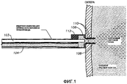
на Фиг.1 дано условное изображение выводящего конца прозрачной светопроводящей инфузионной канюли в соответствии с вариантами осуществления настоящего изобретения;figure 1 is a conditional image of the output end of a transparent light guide infusion cannula in accordance with the variants of implementation of the present invention;
на Фиг.2 дано условное изображение подводящего конца прозрачной светопроводящей инфузионной канюли в соответствии с вариантами осуществления настоящего изобретения;figure 2 is a conditional image of the inlet end of a transparent light guide infusion cannula in accordance with the variants of implementation of the present invention;
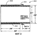
на Фиг.3 дано условное изображение прозрачной светопроводящей инфузионной канюли в соответствии с вариантами осуществления настоящего изобретения;figure 3 is a conditional image of a transparent light guide infusion cannula in accordance with the variants of implementation of the present invention;
на Фиг.4 дано условное изображение оптического волокна/20 размера канюли примерной конфигурации в соответствии с вариантами осуществления настоящего изобретения;figure 4 is a conditional image of the optical fiber / 20 size of the cannula of the approximate configuration in accordance with the variants of implementation of the present invention;
на Фиг.5 дано условное изображение прозрачной светопроводящей инфузионной канюли, где оптическое волокно и трубопровод текучей среды сходятся вместе проксимальнее входной апертуры в склеру в соответствии с вариантами осуществления настоящего изобретения;figure 5 is a conditional image of a transparent light guide infusion cannula, where the optical fiber and the fluid pipe converge together proximal to the inlet aperture in the sclera in accordance with embodiments of the present invention;
на Фиг.6 дано условное изображение авторассекающей (и самоудерживающейся, если к канюле добавлен кольцевой упор) прозрачной светопроводящей инфузионной канюли в соответствии с вариантами осуществления настоящего изобретения;Fig. 6 is a schematic representation of an auto-dissecting (and self-retaining, if an annular stop is added to the cannula) transparent light guide infusion cannula in accordance with embodiments of the present invention;
на Фиг.7 дано условное изображение авторассекающей (и самоудерживающейся, если к канюле добавлен кольцевой упор), прозрачной светопроводящей инфузионной канюли в соответствии с вариантами осуществления настоящего изобретения;Fig. 7 is a schematic representation of an auto-dissecting (and self-retaining if an annular stop is added to the cannula) transparent transmissive infusion cannula in accordance with embodiments of the present invention;
на Фиг.8-11 проиллюстрировано прохождение отдельных лучей и общего светового пучка через канюлю как в условиях текучей среды (например солевой раствор), так и в условиях газа (например воздух) в соответствии с вариантами осуществления настоящего изобретения;FIGS. 8-11 illustrate the passage of individual beams and a common light beam through a cannula, both in a fluid environment (eg, saline solution) and in gas conditions (eg, air) in accordance with embodiments of the present invention;
на Фиг.12-14 показаны различные оптические конструктивные особенности прозрачной светопроводящей инфузионной канюли в соответствии с вариантами осуществления настоящего изобретения;12-14 show various optical design features of a transparent light guide infusion cannula in accordance with embodiments of the present invention;
на Фиг.15 показана «горячая точка», образованная нерассеянным светом, проходящим напрямую от дистального конца оптического волокна через отверстие в конце прямой канюли и внутрь глаза;on Fig shows a "hot spot" formed by the scattered light passing directly from the distal end of the optical fiber through the hole at the end of the straight cannula and into the eye;
на Фиг.16 показано решение проблемы «горячей точки», проиллюстрированной на Фиг.15, в соответствии с вариантами осуществления настоящего изобретения;FIG. 16 shows a solution to the “hot spot” problem illustrated in FIG. 15, in accordance with embodiments of the present invention;
на Фиг.17 показано решение проблемы «горячей точки», проиллюстрированной на Фиг.15, использующее конфигурацию искривленной металлической канюли, которая дает в результате широкоугольный выходящий световой пучок либо в газе (таком как воздух) или в жидкости (такой как солевой раствор) в соответствии с вариантами осуществления настоящего изобретения;FIG. 17 shows a solution to the “hot spot” problem illustrated in FIG. 15 using a curved metal cannula configuration that results in a wide-angle output light beam either in a gas (such as air) or in a liquid (such as saline) in in accordance with embodiments of the present invention;
на Фиг.18 показано решение проблемы «горячей точки», проиллюстрированной на Фиг.15, использующее конфигурацию искривленной прозрачной канюли, которая дает в результате широкоугольный выходящий световой пучок либо в газе (таком как воздух), или в жидкости (такой как солевой раствор) в соответствии с вариантами осуществления настоящего изобретения;FIG. 18 shows a solution to the “hot spot” problem illustrated in FIG. 15 using a curved transparent cannula configuration that results in a wide-angle output light beam either in a gas (such as air) or in a liquid (such as saline) in accordance with embodiments of the present invention;
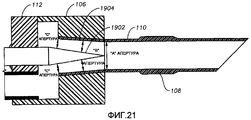
на Фиг.19-21 дано условное изображение прозрачной светопроводящей инфузионной канюли, которая содержит в себе коническое оптическое волокно в соответствии с вариантами осуществления настоящего изобретения;on Fig.21-21 given a conditional image of a transparent light guide infusion cannula, which contains a conical optical fiber in accordance with the variants of implementation of the present invention;
на Фиг.22 показано получающееся в результате большое угловое расхождение излучаемого светового пучка в воздушной среде, связанное с прозрачной светопроводящей инфузионной канюлей Фиг.19-21 в соответствии с вариантами осуществления настоящего изобретения;on Fig shows the resulting large angular divergence of the emitted light beam in the air, associated with a transparent light guide infusion cannula Fig.19-21 in accordance with the variants of implementation of the present invention;
на Фиг.23 дано условное изображение прозрачной светопроводящей инфузионной канюли, имеющей расположенное под углом отражающее покрытие, препятствующее излучаемому свету напрямую освещать посредством канюли, в соответствии с вариантами осуществления настоящего изобретения; иon Fig given a conditional image of a transparent light guide infusion cannula having an angled reflective coating that prevents emitted light from being directly illuminated by a cannula, in accordance with embodiments of the present invention; and
на Фиг.24 дано условное изображение конусообразной формы оптического волокна составного параболического концентратора/усеченного конуса.on Fig given a conventional image of the conical shape of the optical fiber composite parabolic hub / truncated cone.
Описание изобретенияDescription of the invention
Предпочтительные варианты осуществления настоящего изобретения проиллюстрированы на чертежах, для ссылок к одинаковым и подобным частям различных чертежей использованы одинаковые позиции.Preferred embodiments of the present invention are illustrated in the drawings, the same reference numbers are used to refer to the same and similar parts of different drawings.
На Фиг.1 дано условное изображение выводящего конца прозрачной светопроводящей инфузионной канюли в соответствии с вариантами осуществления настоящего изобретения. Этот вариант осуществления изобретения предcтавляет собой светопроводящую инфузионную канюлю 100, которая может включать в себя следующие компоненты: (1) эндосветильник 100, содержащий конусовидное оптическое волокно 101 с высокой числовой апертурой (А), такое как оптическое волокно 103 Toray расширенного диаметра 20 mil и числовой апертуры 0,63, (2) канал 104 для перемещения жидкости или газа, (3) раструб 106, где эндосветильник и канал сходятся вместе, (4) расположенную после раструба прозрачную канюлю 108, которая может включать в себя самоудерживающее кольцо и (5) высокоотражающее покрытие 110 на части наружной боковой поверхности канюли. При желании дистальная часть прозрачной канюли может быть изогнута или может включать в себя конструктивные особенности, такие как рассеивающая, дифракционная или микронноупорядоченная поверхность, рассеивающая свет под заданным угловым распространением.Figure 1 shows a conditional image of the output end of a transparent light guide infusion cannula in accordance with the variants of implementation of the present invention. This embodiment of the invention is a light
На Фиг.2 дано условное изображение подводящего конца прозрачной светопроводящей инфузионной канюли в соответствии с вариантами осуществления настоящего изобретения. Этот подводящий конец может содержать в себе «Осветительный зонд высокой пропускной способности», раскрытый в предварительной патентной заявке США №60/653265, поданной 15 февраля 2005, и непредварительной патентной заявке США №11/354615, поданной 15 февраля 2006, которые являются, таким образом, включенными посредством ссылки во всей своей полноте для всех целей.Figure 2 shows the conditional image of the inlet end of a transparent light guide infusion cannula in accordance with the variants of implementation of the present invention. This lead-in end may include the “High-throughput Lighting Probe” disclosed in US Provisional Patent Application No. 60/653265, filed February 15, 2005, and US Non-Provisional Patent Application No. 11/354615, filed February 15, 2006, which are such incorporated by reference in its entirety for all purposes.
Этапы создания подводящего конца инфузионной канюли в соответствии с вариантами осуществления настоящего изобретения могут включать в себя разные этапы. Вначале оптическое волокно 202 большого диаметра и со средней числовой апертурой может быть соединено с коническим оптическим волокном 204, имеющим высокую числовую апертуру, как описано в предварительной патентной заявке США №60/653265, поданной 15 февраля 2005. Например, соединение оптического волокна 202 диаметром 29,5 mil и имеющим числовую апертуру 0,5 с Toray оптическим волокном 204 диаметра, сужающегося с 29,5 mil до 20 mil (1 mil = 0,001 дюйма = 25,4 мкм), и имеющим числовую апертуру 0,63 посредством использования оптического адгезива 206 Dymax 142-M. Затем может быть обеспечен гибкий пластиковый трубопровод 208 для перемещения текучей среды или газа. При желании оптическое волокно 202 и трубопровод 208 могут быть заключены внутрь защитной оболочки 210 для того, чтобы образовать единый кабель. Затем стеклянная цилиндрическая канюля, которая имеет достаточную длину для того, чтобы пройти через склеру (по меньшей мере 0,53") и у которой, при желании, имеется тороидальное удерживающее кольцо, чтобы позволить канюле оставаться внутри глаза после ее установки, подвергается механической обработке или получается литьем под давлением из прозрачного пластика.The steps for creating the lead end of the infusion cannula in accordance with embodiments of the present invention may include various steps. Initially, a large diameter
На Фиг.3 дано условное изображение прозрачной светопроводящей инфузионной канюли в соответствии с вариантами осуществления настоящего изобретения. В этом примере 20 размера (калибра) прозрачная канюля 300 может быть изготовлена из акрилопласта и может иметь внутренний диаметр 31 mil, наружный диаметр 36 mil и длину 58 mil. Покрытия 302 могут быть нанесены на части внутреннего или наружного диаметра цилиндрической поверхности 304 канюли 300 посредством использования металлического или диэлектрического процесса создания многослойного покрытия или посредством использования другого подобного процесса. В примере, представленном на Фиг.3, длина покрытия наружной цилиндрической поверхности канюли составляет 38 mil. Покрытие должно иметь высокую отражающую способность и быть биологически совместимым. Серебро и алюминий являются покрытиями, которые имеют высокую отражающую способность к видимому свету и которые имеют подходящую биологическую совместимость.Figure 3 shows a conditional image of a transparent light guide infusion cannula in accordance with the variants of implementation of the present invention. In this example, a 20 size (gauge)
Возвращаясь к Фиг.1, пластиковый раструб 106 и пластиковая заглушка 112, сформированные посредством машинной обработки или литьем под давлением, присоединяют оптическое волокно 103 и трубопровод 104 текучей среды к прозрачной канюле 108. Пластиковый раструб 106 и пластиковая заглушка 112 могут быть изготовлены по отдельности, а затем скреплены защелкиванием и/или склеены вместе, или пластиковый раструб 106 и заглушка 112 могут быть изготовлены как одна единая часть. Прозрачная канюля 108 крепится защелкиванием и/или склеиванием внутри дистального конца пластикового раструба 106. Альтернативно прозрачная канюля и раструб могут быть изготовлены как одна непрерывная часть. Пластиковая заглушка имеет два отверстия - одно для оптического волокна и одно для пластикового трубопровода. Оптическое волокно и трубопровод являются вставленными внутрь заглушки. Пластиковая заглушка располагает оптическое волокно латерально, таким образом, что оно оказывается расположенным коаксиально оси прозрачной канюли. Оптическое волокно 103 вставляют через пластиковую заглушку 112 таким образом, что его дистальный конец является расположенным с надлежащим промежутком по отношению к проксимальному концу канюли (см. «фундаментальные принципы», пояснение ниже), затем оптическое волокно крепится к пластиковой заглушке 112.Returning to FIG. 1, a
На Фиг.4 дано условное изображение оптического волокна 103 (20 размера) канюли 108, сконфигурированной в соответствии с вариантами осуществления настоящего изобретения. В этом примере зазор между канюлей и оптическим волокном составляет 7,7 mil. Кроме того, пластиковый трубопровод 104 может, в случае необходимости, быть приклеен к пластиковой заглушке 112.Figure 4 is a conditional image of the optical fiber 103 (20 sizes) of the
Прозрачная светопроводящая инфузионная канюля, представленная вариантами реализации настоящего изобретения, обеспечивает: (1) более высокое светопропускание, чем конкурирующая светопроводящая инфузионная канюля; (2) лучшую скорость потока текучей среды, чем конкурирующая светопроводящая инфузионная канюля; (3) одновременно включает в себя улучшенное светопропускание и улучшенную скорость потока в такой же светопроводящей инфузионной канюле; и (4) обеспечивает высокое светопропускание и высокую скорость потока сквозь канюлю 20 размера.The transparent light guide infusion cannula represented by the embodiments of the present invention provides: (1) higher light transmission than a competing light guide infusion cannula; (2) a better fluid flow rate than a competing light guide infusion cannula; (3) at the same time includes improved light transmission and improved flow rate in the same light guide infusion cannula; and (4) provides high light transmission and high flow rate through the
Принципы, описанные в предварительной патентной заявке США №60/653265, дают возможность свету проходить через небольшую апертуру (апертура в дистальном конце конусовидного оптического волокна с высокой числовой апертурой), и, в то же время, достигается очень высокое относительное светопропускание. Апертура в дистальном конце оптического волокна меньше, чем апертура прозрачной канюли.The principles described in U.S. provisional patent application No. 60/653265 allow light to pass through a small aperture (an aperture at the distal end of a cone-shaped optical fiber with a high numerical aperture), and at the same time, very high relative light transmission is achieved. The aperture at the distal end of the optical fiber is smaller than the aperture of the transparent cannula.
Поскольку дистальная апертура конического оптического волокна меньше, чем апертура прозрачной канюли, то почти весь свет, излучаемый оптическим волокном, пройдет через апертуру внутреннего диаметра на проксимальном конце прозрачной канюли, даже если дистальный конец оптического волокна расположен с некоторым промежутком по отношению к проксимальному концу прозрачной канюли. Максимальный разделяющий промежуток, при котором поддерживается высокая пропускная способность, примерно определяется как S=[(Dc-Df)/2]/tang θcutoff, где Dc = внутренний диаметр прозрачной канюли, Df = диаметр на дистальном конце оптического волокна и θcutoff = угол прямого выхода оптического волокна. Для оптического волокна Toray 20 mil с числовой апертурой 0,63 в воздушной среде и прозрачной канюли с внутренним диаметром 31 mil, в этом случае угол прямого выхода = 39,1° и максимальный разделяющий промежуток S=6,8 mil.Since the distal aperture of the conical optical fiber is smaller than the aperture of the transparent cannula, almost all the light emitted by the optical fiber will pass through the aperture of the inner diameter at the proximal end of the transparent cannula, even if the distal end of the optical fiber is located at some distance relative to the proximal end of the transparent cannula . The maximum separation gap at which high throughput is maintained is approximately defined as S = [(Dc-Df) / 2] / tang θcutoff, where Dc = inner diameter of the transparent cannula, Df = diameter at the distal end of the optical fiber, and θcutoff = right angle output optical fiber. For a
Если на прозрачную канюлю не нанесено покрытие, то лучи света, поступающие в проксимальную апертуру внутреннего диаметра канюли, пройдут через стенки канюли и потеряются посредством спектрального поглощения внутри склеры. Однако, если часть внутреннего или наружного диаметра цилиндрической боковой стенки канюли (часть, которая проходит через склеру) является покрытой металлическим или многослойным диэлектрическим покрытием с высокой отражающей способностью, то свет внутри канюли отражается покрытием таким образом, что он будет оставаться внутри канюли при прохождении через склеру. Покрытие является выполненным таким образом, что оно заканчивается, как только канюля оказывается установленной в склере. Когда свет проходит через часть канюли, которая не является покрытой, свет проходит через стенку канюли и освещает сетчатку в пределах внутреннего пространства глаза.If no coating is applied to the transparent cannula, then the rays of light entering the proximal aperture of the inner diameter of the cannula will pass through the walls of the cannula and be lost through spectral absorption inside the sclera. However, if part of the inner or outer diameter of the cylindrical side wall of the cannula (the part that passes through the sclera) is coated with a metal or multilayer dielectric coating with high reflectivity, the light inside the cannula is reflected by the coating so that it remains inside the cannula when passing through sclera. The coating is designed so that it ends as soon as the cannula is installed in the sclera. When light passes through a part of the cannula that is not covered, light passes through the wall of the cannula and illuminates the retina within the inner space of the eye.
Размещение оптического волокна и канюли с некоторым промежутком друг от друга дает возможность текучей среде обтекать дистальный конец оптического волокна и протекать внутри прозрачной канюли с намного более высокой скоростью потока, чем это было бы возможно, если бы расстояние S между оптическим волокном и канюлей было бы равным 0. Варианты реализации настоящего изобретения обеспечивают промежуточное пространство между оптическим волокном и канюлей таким образом, что площадь поперечного сечения канала текучей среды оптимизирована всюду (то есть не существуют никаких участков, где бы площадь поперечного сечения потока была бы небольшой). Скорость потока должна быть примерно пропорциональной площади поперечного сечения.Placing the optical fiber and the cannula at a certain distance from each other allows fluid to flow around the distal end of the optical fiber and flow inside the transparent cannula at a much higher flow rate than would be possible if the distance S between the optical fiber and the cannula were equal 0. Embodiments of the present invention provide an intermediate space between the optical fiber and the cannula so that the cross-sectional area of the fluid channel is optimized in Yuda (ie there are no areas where the cross-sectional area of the flow would be small). The flow rate should be approximately proportional to the cross-sectional area.
Промежуточное пространство между оптическим волокном и канюлей является выполненным таким образом, что достигается лучший компромисс между высоким светопропусканием и высокой скоростью потока текучей среды. В 20 размере (калибре) конфигурации, изображенной на Фиг.4, теоретически спрогнозированное светопропускание в воздушной среде (по сравнению с оптическим волокном 20 размера, диаметра 29,5 mil и имеющим числовую апертуру 0,5) составляет ~82%, а площадь сечения потока составляет 0,000755 квадратных дюйма. Это представляет 1,7-кратное улучшение светопропускания и 1,74-кратное улучшение площади сечения потока по сравнению с некоторыми конфигурациями светопроводящей инфузионной канюли предшествующего уровня техники (см. «Предшествующий уровень техники»).The intermediate space between the optical fiber and the cannula is designed in such a way that a better compromise is achieved between high light transmission and high fluid flow rate. In the 20 size (gauge) configuration shown in FIG. 4, the theoretically predicted light transmission in air (compared to a
Кольцевой самоудерживающий «упор» 1404 на наружной цилиндрической поверхности канюли является выполненным с возможностью обеспечивать удерживание светопроводящей инфузионной канюли, помещенной внутри глаза, после введения канюли.An annular self-retaining "emphasis" 1404 on the outer cylindrical surface of the cannula is made with the ability to ensure retention of the light guide infusion cannula placed inside the eye after insertion of the cannula.
Варианты осуществления настоящего изобретения максимизируют светопропускание и скорость потока через светопроводящую инфузионную канюлю внутрь глаза, давая, например, следующие ограничения:Embodiments of the present invention maximize light transmission and flow rate through a light guide infusion cannula into the eye, giving, for example, the following limitations:
лампа светильника является выполненной с возможностью фокусировать свет внутрь оптического волокна 20 размера (диаметр 0,0295");the lamp lamp is configured to focus light into an optical fiber of size 20 (diameter 0.0295 ");
инфузионная канюля должна иметь наружный диаметр не более 0,036" для того, чтобы обеспечить возможность самоутягивания при использовании 20 размера в хирургии;the infusion cannula should have an outer diameter of not more than 0.036 "in order to allow self-retraction when using
инфузионная канюля должна иметь минимальную толщину стенки, сохраняя минимально необходимую прочность.the infusion cannula should have a minimum wall thickness while maintaining the minimum necessary strength.
Известно множество предшествующих попыток, направленных на решение этой проблемы. Конфигурации имеют коммерчески общедоступный зонд светопроводящей инфузионной канюли 20 размера, который состоит из: (1) неконусовидного оптического волокна диаметром 500 мкм (20 mil), длиной несколько футов, предположительно с 0,5 числовой апертурой, (2) гибкого пластикового трубопровода для проведения текучей среды или газа, (3) раструба, который соединяет оптическое волокно и пластиковый трубопровод несколькими дюймами выше дистального конца оптического волокна, (4) сегмента оптического волокна и трубопровода, расположенных вниз от раструба, в котором оптическое волокно находится внутри трубопровода, (5) 20 размера металлической канюли внутреннего диаметра 31 mil, в которую вставлена комбинация из трубопровода и оптического волокна (трубопровод скользит поверх канюли, в то время как оптическое волокно пропускается через канюлю) и (6) дистального конца оптического волокна длиной ~40 mil позади дистального конца канюли, в которой оптическое волокно линейно сужается до фактической точки. Эта конфигурация в результате дает площадь поперечного сечения потока 0,000441 квадратного дюйма и измеренное светопропускание (в воздушной среде) 47% по сравнению со стандартным 20 размера эндосветильником Alcon (при использовании светильника Accurus или AHBI).Many previous attempts to solve this problem are known. The configurations have a
Проблема этой конфигурации состоит в том, что оптическое волокно и текучая среда конкурируют за ту же самую площадь поперечного сечения внутри ограниченного внутреннего диаметра 31 mil внутри 20 размера канюли. В связи с этим существует прямое отношение между площадью поперечного сечения оптического волокна (и соответственно светопропусканием) и площадью поперечного сечения текучей среды (и соответственно скоростью потока текучей среды). Когда одно из них увеличивается, другое пропорционально снижается. Нет никакого способа при таком подходе избежать указанного соотношения.The problem with this configuration is that the optical fiber and the fluid compete for the same cross-sectional area within a limited internal diameter of 31 mil inside the 20 cannula size. In this regard, there is a direct relationship between the cross-sectional area of the optical fiber (and therefore the light transmission) and the cross-sectional area of the fluid (and, accordingly, the flow rate of the fluid). When one of them increases, the other decreases proportionally. There is no way to avoid this ratio with this approach.
Второе решение представлено Toy Alcon, которая представляет 19 размера светопроводящую инфузионную канюлю, которая аналогична конфигурации Synergetics за исключением того, что: (1) внутренний диаметр канюли составляет 42,5 mil, (2) внутренний диаметр канюли составляет 37,5 mil, (3) диаметр оптического волокна составляет 30 mil и (4) площадь поперечного сечения текучей среды составляет 0,000398 квадратных дюйма.The second solution is presented by Toy Alcon, which presents a 19-size light guide infusion cannula that is similar to the Synergetics configuration except that: (1) the inner diameter of the cannula is 42.5 mil, (2) the inner diameter of the cannula is 37.5 mil, (3 a) the diameter of the optical fiber is 30 mil and (4) the cross-sectional area of the fluid is 0.000398 square inches.
Подобно конфигурации «Synergetics» проблема при использовании этой конфигурации состоит в том, что оптическое волокно и текучая среда конкурируют за ту же самую площадь поперечного сечения внутри ограниченного внутреннего диаметра 37,5 mil внутри 19 размера канюли. В связи с этим существует прямое соотношение между площадью поперечного сечения оптического волокна (и соответственно светопропусканием) и площадью поперечного сечения текучей среды (и соответственно скоростью потока текучей среды). Когда одно из них увеличивается, другое пропорционально снижается. Нет никакого способа при таком подходе избежать этого соотношения.Similar to the Synergetics configuration, the problem with this configuration is that the optical fiber and the fluid compete for the same cross-sectional area within the limited internal diameter of 37.5 mil inside the 19 cannula size. In this regard, there is a direct relationship between the cross-sectional area of the optical fiber (and therefore the light transmission) and the cross-sectional area of the fluid (and, accordingly, the flow rate of the fluid). When one of them increases, the other decreases proportionally. There is no way with this approach to avoid this ratio.
Другая проблема при использовании этой конфигурации состоит в том, что наружный диаметр имеет 19 размер (42,5 mil) вместо 20 размера (36 mil). Больший размер канюли делает офтальмологические операции более травматичными, препятствует самоутягиванию и приводит к тому, что время, необходимое для заживления, становится более продолжительным.Another problem with this configuration is that the outer diameter is 19 size (42.5 mil) instead of 20 size (36 mil). The larger size of the cannula makes ophthalmic surgery more traumatic, prevents self-tightening and leads to the fact that the time required for healing becomes longer.
Варианты реализации настоящего изобретения обеспечивают различные преимущества по сравнению с описанными предшествующими решениями. Например, может быть обеспечена 20 размера светопроводящая инфузионная канюля вместо 19 размера. Меньший, 20 размер (внутренний диаметр составляет 36 mil) при новой конфигурации приводит к менее травматичным офтальмологическим операциям, самоутягиванию и уменьшению времени заживления.Embodiments of the present invention provide various advantages over the described previous solutions. For example, a
В приведенном в качестве примера варианте реализации настоящего изобретения на Фиг.4 осуществлено 1,74-кратное улучшение светопропускания (в воздушной среде) по сравнению с конфигурацией «Synergetics» предшествующего уровня техники (при использовании светильника Accurus или AHBI). Кроме того, осуществлено 1,7-кратное улучшение площади поперечного сечения и скорости потока над «Synergetics» предшествующего уровня техники и 1,90-кратное улучшение площади поперечного сечения и скорости потока над Alcon предшествующего уровня техники.In an exemplary embodiment of the present invention, FIG. 4 has a 1.74-fold improvement in light transmission (in air) compared to the prior art Synergetics configuration (using Accurus or AHBI). In addition, a 1.7-fold improvement in cross-sectional area and flow rate over Synergetics prior art and a 1.90-fold improvement in cross-sectional area and flow rate over Alcon prior art.
На Фиг.5-7 проиллюстрированы другие возможные варианты осуществления настоящего изобретения. На Фиг.5 представлено условное изображение прозрачной светопроводящей инфузионной канюли, где оптическое волокно 103/204 и трубопровод 104 текучей среды сходятся вместе вверху перед входной апертурой склеры в соответствии с вариантами осуществления настоящего изобретения. На Фиг.6 и 7 изображена авторассекающая (и самоудерживающаяся, если к канюле добавлен кольцевой упор) прозрачная светопроводящая инфузионная канюля 600, которая включает в себя подпружиненную металлическую рассекающую канюлю 602 и фиксатор 604. В своей начальной позиции, как показано на Фиг.6, рассекающая канюля 602 выведена вперед так, чтобы сделать возможным проведение разреза в склере. При оттягивании фиксатора 604, рассекающая канюля 602 убирается, как показано на Фиг.7, оставляя оптическое волокно 103/204 и прозрачную канюлю 108 в их правильном взаимном расположении, обеспечивая оптимальную комбинацию светопропускания и потока текучей среды.5-7 illustrate other possible embodiments of the present invention. Figure 5 presents a conditional image of a transparent light guide infusion cannula, where the
На Фиг.8-11 проиллюстрировано прохождение отдельных лучей и общего светового пучка через канюлю как в условиях текучей среды (например, солевого раствора), так и в условиях газа (например, воздуха) в соответствии с вариантами реализации настоящего изобретения. В условиях газа угловое расхождение светового пучка является более широким, чем в условиях солевого раствора. Таким образом, любые потери светопропускания, обусловленные непрохождением света через проксимальную входную апертуру канюли (вследствие слишком большого зазора между оптическим волокном и канюлей), будут большими в условиях газа, чем в условиях текучей среды.On Fig-11 illustrates the passage of individual beams and a common light beam through the cannula both in a fluid medium (for example, saline solution) and in gas conditions (for example, air) in accordance with embodiments of the present invention. Under gas conditions, the angular divergence of the light beam is wider than under saline conditions. Thus, any loss of light transmission due to the passage of light through the proximal input aperture of the cannula (due to too much clearance between the optical fiber and the cannula) will be greater under gas conditions than in a fluid environment.
Предшествующий уровень техники, рассмотренный выше, включает в себя оптическое волокно, дистальный конец которого конусообразно сужается почти до точки. Результатом этой конусности является угловое расширение излучаемого светового пучка под большим углом, чем световой пучок, излучаемый от неконического оптического волокна. Варианты реализации изобретения прозрачной светопроводящей инфузионной канюли, изображенной на Фиг.1-11, включают в себя неконическое оптическое волокно и прямую неконусовидную канюлю. Таким образом, угловое расхождение света, излучаемого в этом варианте реализации изобретения, примерно равно угловому расхождению непосредственно от неконического оптического волокна; то есть намного более сужено угловое расхождение, чем в предшествующем уровне техники. Для некоторых применений настоящего изобретения было бы желательно увеличить угловое расхождение излучаемого светового пучка, таким образом, чтобы освещение сетчатки было относительно равномерным. Существуют два способа увеличения углового расхождения излучаемого светового пучка: (1) посредством изменения канюли, (2) посредством изменения оптического волокна.The prior art discussed above includes an optical fiber, the distal end of which is tapered in a tapered shape to almost a point. The result of this taper is the angular expansion of the emitted light beam at a larger angle than the light beam emitted from a non-conical optical fiber. Embodiments of the invention of the transparent light guide infusion cannula depicted in FIGS. 1-11 include a non-conical optical fiber and a straight non-conical cannula. Thus, the angular divergence of the light emitted in this embodiment is approximately equal to the angular divergence directly from the non-conical optical fiber; that is, the angular divergence is much more narrowed than in the prior art. For some applications of the present invention, it would be desirable to increase the angular divergence of the emitted light beam so that the retina illumination is relatively uniform. There are two ways to increase the angular divergence of the emitted light beam: (1) by changing the cannula, (2) by changing the optical fiber.
Одной из модификаций канюли является изготовление части или всей канюли отражающими посредством использования металлического или диэлектрического покрытия поверх выбранной области прозрачной канюли или посредством изготовления самой канюли из отражающего металла. Другие модификации канюли сопряжены с включением в себя оптических конструктивных особенностей, таких как рассеивающая поверхность, дифракционная поверхность и/или совокупность микролинз, для того, чтобы рассеивать свет под желаемым угловым распространением. Альтернативно рассеивающая, дифракционная, отражающая или преломляющая пленка может быть нанесена подобно переводной картинке на наружную цилиндрическую поверхность дистальной части прозрачной канюли для того, чтобы обеспечить желаемое распределение света. Эти оптические конструктивные особенности изображены на Фиг.12-14. На Фиг.12 представлена прозрачная канюля 1202, имеющая поверхностный светорассеиватель 1204, расположенный снаружи канюли 1202 или изнутри канюли 1202. Также может быть предусмотрена непрозрачная канюля 1206, имеющая поверхностный светорассеиватель 1208, расположенный на внутреннем диаметре канюли. На Фиг.13 показано использование светорассеивающих красок 1302 на внутренней поверхности или наружной поверхности канюли 1304 или использование толстого формообразующего светорассеивающего материала 1306 в самой канюле 1304. На Фиг.14 представалена прозрачная канюля 1402, в которой применяются отражающие линзы 1404 на цилиндрических поверхностях для того, чтобы обеспечить желаемое распределение света.One modification of the cannula is to make part or all of the cannula reflective by using a metal or dielectric coating over a selected area of the transparent cannula or by manufacturing the cannula itself from a reflective metal. Other modifications to the cannula involve the incorporation of optical design features, such as a scattering surface, a diffractive surface and / or a combination of microlenses, in order to scatter light under the desired angular propagation. Alternatively, a scattering, diffraction, reflective or refractive film may be applied like a decal onto the outer cylindrical surface of the distal portion of the transparent cannula in order to provide the desired light distribution. These optical design features are shown in FIGS. 12-14. 12 shows a
Однако все эти конструктивные особенности имеют проблему - «горячую точку» 1502, вызываемую нерассеянным светом 1504, идущим напрямую из дистального конца оптического волокна 103/204 через отверстие в конце прямой канюли и внутрь глаза (см. Фиг.15). Решением проблемы «горячей точки» является изгибание прозрачной канюли 1600 или непрозрачной канюли 1602 таким образом, чтобы никакие лучи света не могли проходить напрямую от оптического волокна 103/204 внутрь глаза без сталкивания с канюлей 1602 (см. Фиг.16). На Фиг.17 проиллюстрирована искривленная конфигурация 1700 металлической канюли, которая в результате обеспечивает широкоугольный выходящий световой пучок либо в газе (таком как воздух) или в жидкости (такой как солевой раствор). Подобные свойства углового расхождения достигаются в искривленной конфигурации 1800 прозрачной канюли на Фиг.18 (в которой большая часть канюли, кроме скошенного дистального конца, является покрытой отражающим металлом).However, all these design features have a problem - a "hot spot" 1502 caused by the scattered light 1504 coming directly from the distal end of the
Другим средством углового расширения светового пучка является заострение на конус дистального конца 1902 оптического волокна 103/204. Вариант реализации этого изобретения, который включает в себя коническое оптическое волокно, проиллюстрирован на Фиг.19-21. В этом предпочтительном варианте реализации изобретения проксимальный конец 1904 канюли 108 является немного расширенным таким образом, что площадь поперечного сечения между оптическим волокном и канюлей является не меньшей, чем область выводящего конца канюли (которая составляет 0,000755 квадратных дюймов в примере на Фиг.20 и Фиг.21). Получаемое большое угловое расхождение излучаемого светового пучка в воздушной среде проиллюстрировано на Фиг.22. Эта конфигурация имеет на 36% больший выход света и на 71% большую площадь поперечного сечения потока, чем при подходе, используемом в конфигурации «Synergetics». Кроме того, расположенное под углом отражающее покрытие 2302 может быть добавлено к прозрачной канюле 100, как на Фиг.23, для того, чтобы предотвратить прямое освещение из канюли излучаемым светом.Another means of angular expansion of the light beam is to sharpen the cone of the
Для оптического волокна, которое передает световой пучок с половинным углом θin расхождения светового пучка и которое выполнено с возможностью эффективно излучать свет внутри расходящегося однородного под углом светового пучка с половинным углом θout расхождения, линейная конусность не является оптимальной конусообразной формой. Для условного двухмерного оптического волокна (то есть, где оптическое волокно и лучи полностью ограничены внутри двухкоординатной плоскости), оптимальной конусообразной формой является сложный параболический концентратор, пристыкованный к усеченному линейно-конусному конусу (как проиллюстрировано в примере на Фиг.24). Отношение диаметра дистального оптического волокна к диаметру проксимального оптического волокна равняется sin θin/sin θout. Для этой конусообразной формы, пренебрегая потерями френелевского отражения, эффективность излучения в окружающей воздушной среде составляет 100%, и получаемый в результате излучаемый световой пучок имеет однородную светимость для углов такой величины, как θout и является нулевым для углов больших, чем θout.For an optical fiber that transmits a light beam with a half angle θin of divergence of the light beam and which is configured to efficiently emit light inside a diverging uniform at an angle of the light beam with half angle θout of divergence, linear taper is not an optimal conical shape. For a conditional two-dimensional optical fiber (that is, where the optical fiber and the rays are completely bounded inside the two-dimensional plane), the optimal conical shape is a complex parabolic hub joined to a truncated linear-conical cone (as illustrated in the example in FIG. 24). The ratio of the diameter of the distal optical fiber to the diameter of the proximal optical fiber is sin θin / sin θout. For this conical shape, neglecting the loss of Fresnel reflection, the radiation efficiency in the ambient air is 100%, and the resulting emitted light beam has uniform luminosity for angles such as θout and is zero for angles greater than θout.
Для реального трехмерного оптического волокна ситуация является более сложной. Некоторые косые лучи (под косыми лучами подразумеваются лучи, которые идут снаружи от плоскости, которая включает в себя ось оптического волокна), которые имеют углы отклонения от оси меньше чем θin, поворачивают назад посредством полного внутреннего отражения и идут обратно по оптическому волокну в направлении источника света. Аналогично некоторые косые лучи с углами отклонения от оси, большими, чем θin, выходят из дистального конца конического оптического волокна. Таким образом, для реального трехмерного оптического волокна отношение пропускания к профилю угла излучаемого светового пучка не будет иметь резкого снижения при θout, но будет быстро снижаться в точке 50%-ного пропускания примерно при θout. Кроме того, вследствие косых лучей, конусообразная форма оптического волокна оптимальной эффективности не является сложным параболическим концентратором/усеченным конусом на Фиг.24, но является намного более сложной формой. Оптимальная форма зависит частично от точного отношения светимости к угловому значению светового пучка, заключенного в оптическое волокно, от рассеивающих свойств, связанных с отклонением от оси оптического волокна, и точного желаемого профиля выхода излученного светового пучка. Эта оптимальная форма может быть определена посредством использования программы по оптическому дизайну, такой как Zemax, которая дает возможность модифицировать конусообразную форму оптического волокна автоматически до тех пор, пока оптимальный желаемый выход не будет достигнут.For a real three-dimensional optical fiber, the situation is more complicated. Some oblique rays (oblique rays mean rays that travel outside the plane that includes the axis of the optical fiber) that have angles of deviation less than θin from the axis, are turned back by total internal reflection, and travel back along the optical fiber in the direction of the source Sveta. Similarly, some oblique rays with deviation angles greater than θin exit the distal end of the conical optical fiber. Thus, for a real three-dimensional optical fiber, the ratio of transmission to the angle profile of the emitted light beam will not have a sharp decrease at θout, but will quickly decrease at a point of 50% transmission at approximately θout. In addition, due to oblique rays, the conical shape of the optical fiber of optimal efficiency is not the complex parabolic hub / truncated cone in FIG. 24, but it is a much more complex shape. The optimal shape depends in part on the exact ratio of the luminosity to the angular value of the light beam enclosed in the optical fiber, on the scattering properties associated with the deviation from the axis of the optical fiber, and on the exact desired exit profile of the emitted light beam. This optimum shape can be determined by using an optical design program such as Zemax, which makes it possible to modify the conical shape of the optical fiber automatically until the optimum desired yield is achieved.
Вариант реализации настоящего изобретения проиллюстрирован на Фиг.19-21. В этом варианте реализации изобретения оптическое волокно линейно конусообразно сужено и эффективность излучения из оптического волокна составляет около 60%. Эта линейная конусность может быть заменена сложной конусообразной формой, подобной конусу сложного параболического концентратора/усеченному конусу на Фиг.24, и получаемая в результате эффективность излучения оптического волокна будет очень близка к 100%. (Дизайн этой оптимальной конусообразной формы оптического волокна учитывает отражающую способность канюли и конусообразную форму, которая влияет на профиль выхода излучаемого светового пучка.) При этом, поскольку для этой оптимальной конусообразной формы оптического волокна дистальный конец оптического волокна не сходится конусообразно в точку, но вместо этого заканчивается дистальной поверхностью с небольшим диаметром, площадь поперечного сечения потока между этим оптическим волокном и канюлей на Фиг.19-21 является ограниченной. Другими словами, текучая среда наталкивается на узкое место в дистальном конце оптического волокна. Это может быть предотвращено посредством перемещения оптического волокна с оптимальной конусностью на небольшое расстояние от канюли (в левую сторону на Фиг.20) и/или повышения угла раструба идущего раструбом проксимального конца оптического волокна. Получаемая в результате комбинация между оптическим волокном и канюлей будет сохранять высокую площадь сечения потока 0,000755 квадратных дюйма и будет потенциально иметь еще большую световую пропускную способность, чем вариант реализации изобретения Фиг.19-21.An embodiment of the present invention is illustrated in FIGS. 19-21. In this embodiment, the optical fiber is linearly conically narrowed and the radiation efficiency from the optical fiber is about 60%. This linear taper can be replaced by a complex cone-shaped shape similar to the cone of a complex parabolic concentrator / truncated cone in FIG. 24, and the resulting optical fiber emission efficiency will be very close to 100%. (The design of this optimal conical shape of the optical fiber takes into account the reflectivity of the cannula and the conical shape, which affects the output profile of the emitted light beam.) Moreover, since for this optimal conical shape of the optical fiber, the distal end of the optical fiber does not converge conically to a point, but instead ends with a distal surface with a small diameter, the cross-sectional area of the flow between this optical fiber and the cannula in Fig.21-21 is limited. In other words, the fluid encounters a bottleneck at the distal end of the optical fiber. This can be prevented by moving the optical fiber with optimal taper a small distance from the cannula (to the left side in FIG. 20) and / or increasing the angle of the socket of the proximal end of the optical fiber going through the socket. The resulting combination between the optical fiber and the cannula will maintain a high flow cross section of 0.000755 square inches and will potentially have even greater luminous throughput than the embodiment of the invention of FIGS. 19-21.
Таким образом, вариант реализации изобретения является вариантом на Фиг.19-21, который был модифицирован следующим образом: конусообразная форма оптического волокна и конусообразная форма канюли, и взаимное расположение между оптическим волокном и канюлей изменены, чтобы дать в результате систему, которая излучает свет равномерно по всей поверхности сетчатки глаза с оптимальной эффективностью светового потока.Thus, the embodiment of the invention is the embodiment of FIGS. 19-21, which has been modified as follows: the conical shape of the optical fiber and the conical shape of the cannula, and the relative position between the optical fiber and the cannula are changed to result in a system that emits light uniformly over the entire surface of the retina with optimal luminous flux efficiency.
Для среднего специалиста в данной области техники будет понятно, что термины «по существу» или «приблизительно», которые могут использоваться в настоящем описании изобретения, обеспечивают индустриально принятую толерантность к соответствующему им термину. Такая индустриально принятая толерантность колеблется от менее чем одного процента до двадцати процентов и соответствует значениям компонентов, измерениям параметров процесса интегральной схемы, колебаниям температуры, времени повышения и падения, и/или тепловым помехам, но не ограничивается ими. Как будет также понятно среднему специалисту, термин «функционально соединенный», при использовании в настоящем описании, включает в себя непосредственное соединение и опосредованное соединение через другой компонент, элемент, схему или модуль, где для опосредованного соединения вводимый компонент, элемент, схема или модуль не изменяют информацию о сигнале, но могут отрегулировать его текущий уровень, уровень напряжения и/или уровень питания. Как будет также понятно среднему специалисту, выведенный соединительный элемент (то есть, когда один элемент присоединяется к другому элементу посредством вывода) включает в себя непосредственное или опосредованное соединение между двумя элементами таким же образом, как при «функциональном соединении». Как будет также понятно для среднего специалиста, термин «сравнивается благоприятно», который может использоваться в настоящем описании изобретения, указывает, что сравнение между двумя или более элементами, пунктами, сигналами и т.д. обеспечивает желаемое взаимоотношение. Например, когда желаемое взаимоотношение состоит в том, что сигнал 1 имеет большую величину, чем сигнал 2, благоприятное сравнение может быть достигнуто, когда величина сигнала 1 больше, чем величина сигнала 2, или когда величина сигнала 2 меньше, чем величина сигнала 1.It will be understood by one of ordinary skill in the art that the terms “substantially” or “approximately” that may be used in the present specification provide an industrially accepted tolerance for their respective term. Such industrially accepted tolerance ranges from less than one percent to twenty percent and corresponds to, but is not limited to, values of components, measurements of integrated circuit process parameters, fluctuations in temperature, rise and fall times, and / or thermal noise. As will also be appreciated by one of ordinary skill in the art, the term “functionally connected,” as used herein, includes a direct connection and an indirect connection through another component, element, circuit, or module, where for an indirect connection, the input component, element, circuit, or module does not change the signal information, but can adjust its current level, voltage level and / or power level. As will also be appreciated by one of ordinary skill in the art, an inverted connecting element (that is, when one element is connected to another element by means of an output) includes a direct or indirect connection between the two elements in the same manner as with a “functional connection”. As will also be understood by one of ordinary skill in the art, the term “compares favorably”, which may be used in the present description of the invention, indicates that the comparison is between two or more elements, points, signals, etc. provides the desired relationship. For example, when the desired relationship is that
Несмотря на то что настоящее изобретение описано подробно, следует понимать, что различные изменения, замены и изменения могут быть осуществлены к настоящему, не отступая от сущности и объема притязаний описанного изобретения.Although the present invention is described in detail, it should be understood that various changes, substitutions and changes can be made to the present without departing from the essence and scope of the claims of the described invention.
Claims (17)
Applications Claiming Priority (2)
| Application Number | Priority Date | Filing Date | Title |
|---|---|---|---|
| US75117505P | 2005-12-16 | 2005-12-16 | |
| US60/751,175 | 2005-12-16 |
Publications (2)
| Publication Number | Publication Date |
|---|---|
| RU2008129030A RU2008129030A (en) | 2010-01-27 |
| RU2419400C2 true RU2419400C2 (en) | 2011-05-27 |
Family
ID=38008117
Family Applications (1)
| Application Number | Title | Priority Date | Filing Date |
|---|---|---|---|
| RU2008129030/14A RU2419400C2 (en) | 2005-12-16 | 2006-12-18 | Light-conducting infusion cannula |
Country Status (15)
| Country | Link |
|---|---|
| US (1) | US7783346B2 (en) |
| EP (2) | EP2215995B1 (en) |
| JP (1) | JP5491032B2 (en) |
| KR (1) | KR20080078899A (en) |
| CN (2) | CN102614045B (en) |
| AR (1) | AR058556A1 (en) |
| AT (2) | ATE484264T1 (en) |
| AU (1) | AU2006343552B2 (en) |
| BR (1) | BRPI0619992A2 (en) |
| CA (3) | CA2817892C (en) |
| DE (1) | DE602006017581D1 (en) |
| ES (2) | ES2352221T3 (en) |
| RU (1) | RU2419400C2 (en) |
| TW (1) | TW200730156A (en) |
| WO (1) | WO2007133267A1 (en) |
Cited By (3)
| Publication number | Priority date | Publication date | Assignee | Title |
|---|---|---|---|---|
| RU2622446C2 (en) * | 2011-09-23 | 2017-06-15 | Алькон Рисерч, Лтд. | Ophthalmic endoillummators with directed light |
| RU2666585C2 (en) * | 2014-05-16 | 2018-09-11 | Новартис Аг | Imaging probes and associated devices, systems and methods utilising lever arm actuators |
| RU2692201C2 (en) * | 2014-06-19 | 2019-06-21 | Новартис Аг | Surgical probe with interlocking fastening |
Families Citing this family (78)
| Publication number | Priority date | Publication date | Assignee | Title |
|---|---|---|---|---|
| NL1031588C2 (en) * | 2006-04-13 | 2007-10-19 | D O R C Dutch Ophthalmic Res C | Eye surgical instrument. |
| US7654716B1 (en) | 2006-11-10 | 2010-02-02 | Doheny Eye Institute | Enhanced visualization illumination system |
| US20080177257A1 (en) * | 2007-01-23 | 2008-07-24 | Smith Ronald T | Thermally robust illumination probe tip |
| US8968221B2 (en) | 2007-04-17 | 2015-03-03 | Bwt Property, Inc. | Apparatus and methods for phototherapy |
| US7566173B2 (en) * | 2007-07-09 | 2009-07-28 | Alcon, Inc. | Multi-spot ophthalmic laser probe |
| US9402643B2 (en) | 2008-01-15 | 2016-08-02 | Novartis Ag | Targeted illumination for surgical instrument |
| US8882685B2 (en) | 2008-05-27 | 2014-11-11 | Bwt Property, Inc. | Apparatus and methods for phototherapy |
| US8834358B2 (en) | 2009-03-27 | 2014-09-16 | EndoSphere Surgical, Inc. | Cannula with integrated camera and illumination |
| CA2756787C (en) * | 2009-03-27 | 2019-07-09 | EndoSphere Surgical, Inc. | Cannula with integrated camera and illumination |
| JPWO2010126076A1 (en) * | 2009-04-30 | 2012-11-01 | マニー株式会社 | Ophthalmic surgery cannula and method of manufacturing the same |
| KR101068350B1 (en) * | 2009-07-03 | 2011-09-28 | (주)디지털초음파 | Contact SH-Guided-Wave Magnetostrictive Transducers |
| US8292805B2 (en) | 2009-11-10 | 2012-10-23 | Invuity, Inc. | Illuminated suction apparatus |
| ES2552799T3 (en) * | 2009-11-24 | 2015-12-02 | Alcon Research, Ltd. | Single fiber multipoint laser probe for ophthalmic endoillumination |
| AU2010332222B2 (en) * | 2009-12-15 | 2014-11-20 | Alcon Inc. | Multi-spot laser probe |
| US8343106B2 (en) | 2009-12-23 | 2013-01-01 | Alcon Research, Ltd. | Ophthalmic valved trocar vent |
| JP5990103B2 (en) | 2009-12-23 | 2016-09-07 | アルコン リサーチ, リミテッド | Ophthalmic valved trocar cannula |
| EP3372206A1 (en) * | 2010-05-13 | 2018-09-12 | Doheny Eye Institute | Self contained illuminated infusion cannula systems and devices |
| US8689439B2 (en) | 2010-08-06 | 2014-04-08 | Abbott Laboratories | Method for forming a tube for use with a pump delivery system |
| WO2012021451A1 (en) * | 2010-08-09 | 2012-02-16 | Alcon Research, Ltd. | Illuminated surgical instrument |
| US9428254B1 (en) | 2010-09-24 | 2016-08-30 | Katalyst Surgical, Llc | Microsurgical handle and instrument |
| US8377000B2 (en) | 2010-10-01 | 2013-02-19 | Abbott Laboratories | Enteral feeding apparatus having a feeding set |
| US8377001B2 (en) | 2010-10-01 | 2013-02-19 | Abbott Laboratories | Feeding set for a peristaltic pump system |
| CA2818184C (en) | 2010-12-09 | 2018-07-24 | John Christopher Huculak | Optical coherence tomography and illumination using common light source |
| FR2970412B1 (en) * | 2011-01-18 | 2013-12-20 | France Chirurgie Instr | SELF-LOCKING CANNULA |
| US20120203075A1 (en) * | 2011-02-08 | 2012-08-09 | Christopher Horvath | White coherent laser light launched into nano fibers for surgical illumination |
| DE102011011192B4 (en) * | 2011-02-14 | 2019-06-13 | Geuder Aktiengesellschaft | Device for introducing light into a human or animal eye |
| MX347448B (en) * | 2011-08-03 | 2017-04-27 | Alcon Res Ltd | Articulating ophthalmic surgical probe. |
| CA2842474C (en) * | 2011-08-09 | 2019-09-03 | Alcon Research Ltd. | Multi-spot laser surgical probe using faceted optical elements |
| DE102011111285B4 (en) | 2011-08-26 | 2019-02-21 | Geuder Aktiengesellschaft | Device for introducing light and fluid into a human or animal body and method for producing such a device |
| US9216067B2 (en) * | 2011-09-23 | 2015-12-22 | Gholam A. Peyman | Vitreous cutter sleeve and a vitreous cutter system using the same |
| US8979867B2 (en) * | 2011-09-23 | 2015-03-17 | Gholam A. Peyman | Vitreous cutter |
| US9138346B2 (en) | 2012-01-26 | 2015-09-22 | Katalyst Surgical, Llc | Surgical instrument sleeve |
| NL2008455C2 (en) | 2012-03-09 | 2013-09-10 | D O R C Dutch Ophthalmic Res Ct International B V | EYE-SURGICAL LIGHTING UNIT. |
| US9226762B2 (en) | 2012-11-07 | 2016-01-05 | Katalyst Surgical, Llc | Atraumatic microsurgical forceps |
| US10245181B2 (en) | 2012-12-21 | 2019-04-02 | Alcon Research, Ltd. | Grin fiber multi-spot laser probe |
| KR101478463B1 (en) | 2013-10-10 | 2014-12-31 | 가천대학교 산학협력단 | An illumination chopper |
| ES2539523B1 (en) * | 2013-12-31 | 2016-01-13 | Fundación Tekniker | Vitreoctomy device |
| US10022267B2 (en) | 2014-04-21 | 2018-07-17 | Katalyst Surgical, Llc | Method of manufacturing a microsurgical instrument tip |
| US10022200B2 (en) | 2014-08-25 | 2018-07-17 | Peregrine Surgical, Ltd | Microsurgical instrument |
| US9775943B2 (en) | 2014-10-10 | 2017-10-03 | Katalyst Surgical, Llc | Cannula ingress system |
| WO2016077641A1 (en) | 2014-11-12 | 2016-05-19 | Invuity, Inc. | Improved thermally controlled illumination devices |
| ES2873108T3 (en) | 2015-07-13 | 2021-11-03 | Alcon Inc | Vitreous cutter with integrated lighting system |
| US10244931B2 (en) * | 2015-07-13 | 2019-04-02 | Novartis Ag | Illuminated ophthalmic infusion line and associated devices, systems, and methods |
| US20170056047A1 (en) * | 2015-09-02 | 2017-03-02 | MicroAire Surgical Instruments, LLC. | Endoscopic Surgical Devices and Other Surgical Devices |
| US20180147328A1 (en) * | 2015-09-02 | 2018-05-31 | MicroAire Surgical Instruments, LLC. | Endoscopic Surgical Devices and Other Surgical Devices and Methods of Making, Especially Using Polyarylamides, Polyetherimides, Polyether Ether Ketones, and Liquid Crystal Polymers |
| US11173008B2 (en) | 2015-11-01 | 2021-11-16 | Alcon Inc. | Illuminated ophthalmic cannula |
| US10441157B2 (en) | 2015-12-02 | 2019-10-15 | Novartis Ag | Optical fiber having proximal taper for ophthalmic surgical illumination |
| CN108366874B (en) | 2015-12-14 | 2020-10-30 | 爱尔康公司 | Single port hybrid specification surgical device and method |
| US10278785B2 (en) * | 2015-12-18 | 2019-05-07 | Novartis Ag | Method of making diverging-light fiber optics illumination delivery system |
| US9956053B2 (en) | 2016-03-04 | 2018-05-01 | Novartis Ag | Cannula with an integrated illumination feature |
| US10232107B2 (en) | 2016-03-11 | 2019-03-19 | Hans Utz | Illuminated medical infusion |
| EP3471673A1 (en) | 2016-06-16 | 2019-04-24 | Katalyst Surgical, LLC | Reusable instrument handle with single- use tip |
| WO2018037346A2 (en) | 2016-08-25 | 2018-03-01 | Novartis Ag | Planar illuminator for ophthalmic surgery |
| US11110005B2 (en) | 2016-11-17 | 2021-09-07 | Alcon Inc. | Medical instrument with an integrated optical fiber |
| JP6871401B2 (en) | 2016-11-17 | 2021-05-12 | アルコン インコーポレイティド | Medical equipment with built-in optical fiber |
| CA3043796A1 (en) | 2016-12-15 | 2018-06-21 | Novartis Ag | Illuminated surgical probe having a variable illumination numerical aperture |
| US10478266B2 (en) | 2016-12-15 | 2019-11-19 | Novartis Ag | Illuminated surgical probe having multiple optical fibers |
| US10695043B2 (en) | 2017-02-21 | 2020-06-30 | Katalyst Surgical, Llc | Surgical instrument subcomponent integration by additive manufacturing |
| US20180338859A1 (en) * | 2017-05-24 | 2018-11-29 | Novartis Ag | Ophthalmic endoilluminator |
| EP3629957B1 (en) | 2017-05-24 | 2021-06-23 | Alcon Inc. | Illuminated infusion cannula |
| US10729461B2 (en) | 2017-05-24 | 2020-08-04 | Alcon Inc. | Illuminated infusion cannula |
| JP7232813B2 (en) | 2017-08-09 | 2023-03-03 | アルコン インコーポレイティド | Self-illuminating microsurgical cannula device |
| JP7128614B2 (en) * | 2017-08-30 | 2022-08-31 | マニー株式会社 | infusion pipe |
| CN111050682B (en) | 2017-08-30 | 2023-11-03 | 莱谱有限责任公司 | Non-ablative photonic devices and related methods |
| WO2019097338A1 (en) | 2017-11-14 | 2019-05-23 | Novartis Ag | Multi-spot laser probe with illumination features |
| US11471242B1 (en) | 2018-03-14 | 2022-10-18 | Alcon Inc. | Medical instruments with an integrated optical fiber and methods of manufacture |
| US10849640B2 (en) | 2018-05-23 | 2020-12-01 | Katalyst Surgical, Llc | Membrane aggregating forceps |
| US11986423B1 (en) | 2018-06-18 | 2024-05-21 | Gholam A. Peyman | Method of using a vitrectomy instrument |
| US11020270B1 (en) | 2018-06-18 | 2021-06-01 | Gholam A. Peyman | Vitrectomy instrument and a system including the same |
| US11395713B2 (en) | 2018-07-19 | 2022-07-26 | Alcon Inc. | Illuminated cannula |
| AU2020219357A1 (en) * | 2019-02-08 | 2021-08-12 | Rebound Therapeutics Corporation | Lighted cannula system |
| US11564711B2 (en) | 2019-04-25 | 2023-01-31 | Alcon Inc. | Adjustable length infusion cannula |
| CN114340548A (en) * | 2019-07-08 | 2022-04-12 | 史赛克公司 | System and method for targeted spectral illumination |
| US11439429B2 (en) | 2019-07-11 | 2022-09-13 | New View Surgical | Cannula assembly with deployable camera |
| USD993930S1 (en) | 2021-01-21 | 2023-08-01 | Chs Healthcare Ventures Inc | Fuse clip |
| USD1006986S1 (en) | 2021-01-22 | 2023-12-05 | Chs Healthcare Ventures Inc | Electronic illuminator |
| WO2023002287A1 (en) | 2021-07-20 | 2023-01-26 | Alcon Inc. | Infusion cannula |
| US11877956B2 (en) | 2021-08-06 | 2024-01-23 | Alcon Inc. | Vitreoretinal instruments for illumination, fluid aspiration, and photocoagulation |
Family Cites Families (14)
| Publication number | Priority date | Publication date | Assignee | Title |
|---|---|---|---|---|
| US4551129A (en) * | 1983-04-08 | 1985-11-05 | Coleman D Jackson | Technique and apparatus for intraocular and microsurgery including lighter-irrigator hypodermic tube |
| JPS61290950A (en) * | 1985-06-20 | 1986-12-20 | 株式会社トプコン | Infusion apparatus equipped illumination function |
| JPS61253056A (en) * | 1985-05-01 | 1986-11-10 | 株式会社トプコン | Inffusion apparatus with illumination |
| US4820264A (en) | 1985-05-01 | 1989-04-11 | Tokyo Kogaku Kikai Kabushiki Kaisha | Infusion instrument |
| US4699140A (en) * | 1985-07-10 | 1987-10-13 | Iolab Corporation | Instrument for inserting an intraocular lens |
| US5643250A (en) * | 1992-08-07 | 1997-07-01 | O'donnell, Jr.; Francis E. | Laser probe hand piece |
| US5725514A (en) * | 1994-08-15 | 1998-03-10 | A.V.I. - Advanced Visual Instruments, Inc. | Adjustable miniature panoramic illumination and infusion system for retinal surgery |
| IL121450A0 (en) * | 1997-08-01 | 1998-02-08 | Smollett Neil | Ophthalmic surgical equipment |
| US6936053B1 (en) * | 1998-07-02 | 2005-08-30 | Jeffrey N. Weiss | Ocular implant needle |
| US7077848B1 (en) * | 2000-03-11 | 2006-07-18 | John Hopkins University | Sutureless occular surgical methods and instruments for use in such methods |
| US20030169603A1 (en) * | 2002-03-05 | 2003-09-11 | Luloh K. Peter | Apparatus and method for illuminating a field of view within an eye |
| CN2668087Y (en) * | 2003-12-18 | 2005-01-05 | 江门新会新希望眼科医院 | Optical fiber tube with transfusion drivepipe |
| WO2005086693A2 (en) * | 2004-03-05 | 2005-09-22 | Synergetics, Inc. | Microsurgical tubing with infusion cannula |
| MX2007009802A (en) | 2005-02-15 | 2007-09-26 | Alcon Inc | High throughput endo-illuminator probe. |
-
2006
- 2006-12-18 AR ARP060105600A patent/AR058556A1/en not_active Application Discontinuation
- 2006-12-18 CN CN201210107893.0A patent/CN102614045B/en not_active Expired - Fee Related
- 2006-12-18 TW TW095147468A patent/TW200730156A/en unknown
- 2006-12-18 CA CA2817892A patent/CA2817892C/en not_active Expired - Fee Related
- 2006-12-18 EP EP10163486A patent/EP2215995B1/en active Active
- 2006-12-18 EP EP06847681A patent/EP1959886B1/en active Active
- 2006-12-18 ES ES06847681T patent/ES2352221T3/en active Active
- 2006-12-18 JP JP2008545863A patent/JP5491032B2/en active Active
- 2006-12-18 CA CA2817908A patent/CA2817908C/en not_active Expired - Fee Related
- 2006-12-18 US US11/612,234 patent/US7783346B2/en active Active
- 2006-12-18 AT AT06847681T patent/ATE484264T1/en not_active IP Right Cessation
- 2006-12-18 RU RU2008129030/14A patent/RU2419400C2/en not_active IP Right Cessation
- 2006-12-18 CN CN2006800523826A patent/CN101365404B/en not_active Expired - Fee Related
- 2006-12-18 AU AU2006343552A patent/AU2006343552B2/en not_active Ceased
- 2006-12-18 BR BRPI0619992-5A patent/BRPI0619992A2/en not_active IP Right Cessation
- 2006-12-18 ES ES10163486T patent/ES2373368T3/en active Active
- 2006-12-18 WO PCT/US2006/048036 patent/WO2007133267A1/en active Application Filing
- 2006-12-18 CA CA2633422A patent/CA2633422C/en not_active Expired - Fee Related
- 2006-12-18 DE DE602006017581T patent/DE602006017581D1/en active Active
- 2006-12-18 AT AT10163486T patent/ATE526916T1/en not_active IP Right Cessation
- 2006-12-18 KR KR1020087017207A patent/KR20080078899A/en not_active Application Discontinuation
Non-Patent Citations (1)
| Title |
|---|
| ЗАХАРОВ В.Д. Витреоретинальная хирургия. - М., 2003, с.24-33. * |
Cited By (3)
| Publication number | Priority date | Publication date | Assignee | Title |
|---|---|---|---|---|
| RU2622446C2 (en) * | 2011-09-23 | 2017-06-15 | Алькон Рисерч, Лтд. | Ophthalmic endoillummators with directed light |
| RU2666585C2 (en) * | 2014-05-16 | 2018-09-11 | Новартис Аг | Imaging probes and associated devices, systems and methods utilising lever arm actuators |
| RU2692201C2 (en) * | 2014-06-19 | 2019-06-21 | Новартис Аг | Surgical probe with interlocking fastening |
Also Published As
| Publication number | Publication date |
|---|---|
| CN102614045A (en) | 2012-08-01 |
| CA2817892A1 (en) | 2007-11-22 |
| CN101365404B (en) | 2012-06-06 |
| CA2633422A1 (en) | 2007-11-22 |
| EP2215995B1 (en) | 2011-10-05 |
| US20070179430A1 (en) | 2007-08-02 |
| EP1959886A1 (en) | 2008-08-27 |
| CN102614045B (en) | 2014-11-12 |
| AU2006343552A1 (en) | 2007-11-22 |
| RU2008129030A (en) | 2010-01-27 |
| ES2352221T3 (en) | 2011-02-16 |
| ATE484264T1 (en) | 2010-10-15 |
| EP1959886B1 (en) | 2010-10-13 |
| TW200730156A (en) | 2007-08-16 |
| WO2007133267A1 (en) | 2007-11-22 |
| CA2817908C (en) | 2015-06-16 |
| KR20080078899A (en) | 2008-08-28 |
| CA2817892C (en) | 2015-08-25 |
| EP2215995A1 (en) | 2010-08-11 |
| CN101365404A (en) | 2009-02-11 |
| AR058556A1 (en) | 2008-02-13 |
| ES2373368T3 (en) | 2012-02-02 |
| BRPI0619992A2 (en) | 2011-10-25 |
| CA2817908A1 (en) | 2007-11-22 |
| JP2009519766A (en) | 2009-05-21 |
| CA2633422C (en) | 2014-10-21 |
| DE602006017581D1 (en) | 2010-11-25 |
| AU2006343552B2 (en) | 2011-11-10 |
| US7783346B2 (en) | 2010-08-24 |
| ATE526916T1 (en) | 2011-10-15 |
| JP5491032B2 (en) | 2014-05-14 |
Similar Documents
| Publication | Publication Date | Title |
|---|---|---|
| RU2419400C2 (en) | Light-conducting infusion cannula | |
| RU2415657C2 (en) | Surgical wide-angle lamp | |
| RU2449816C2 (en) | Thermally stable tip of lighting probe | |
| JP2021505314A (en) | Multi-input coupled illuminated multi-spot laser probe | |
| EP1850727B1 (en) | High throughput endo-illuminator probe | |
| MX2013012117A (en) | Illuminated microsurgical instrument including optical fiber with beveled end face. | |
| MX2013008284A (en) | White coherent laser light launched into nano fibers for surgical illumination. | |
| RU2575051C2 (en) | Illuminated microsurgical instrument comprising oblique optical fibre |
Legal Events
| Date | Code | Title | Description |
|---|---|---|---|
| PC43 | Official registration of the transfer of the exclusive right without contract for inventions |
Effective date: 20200724 |
|
| MM4A | The patent is invalid due to non-payment of fees |
Effective date: 20201219 |