US10022267B2 - Method of manufacturing a microsurgical instrument tip - Google Patents

Method of manufacturing a microsurgical instrument tip Download PDF

Info

Publication number
US10022267B2
US10022267B2 US14/657,270 US201514657270A US10022267B2 US 10022267 B2 US10022267 B2 US 10022267B2 US 201514657270 A US201514657270 A US 201514657270A US 10022267 B2 US10022267 B2 US 10022267B2
Authority
US
United States
Prior art keywords
blank
flat stock
tip
actuation structure
base
Prior art date
Legal status (The legal status is an assumption and is not a legal conclusion. Google has not performed a legal analysis and makes no representation as to the accuracy of the status listed.)
Active, expires
Application number
US14/657,270
Other versions
US20150297278A1 (en
Inventor
Gregg D Scheller
Current Assignee (The listed assignees may be inaccurate. Google has not performed a legal analysis and makes no representation or warranty as to the accuracy of the list.)
Katalyst Surgical LLC
Original Assignee
Katalyst Surgical LLC
Priority date (The priority date is an assumption and is not a legal conclusion. Google has not performed a legal analysis and makes no representation as to the accuracy of the date listed.)
Filing date
Publication date
Application filed by Katalyst Surgical LLC filed Critical Katalyst Surgical LLC
Priority to US14/657,270 priority Critical patent/US10022267B2/en
Assigned to KATALYST SURGICAL, LLC reassignment KATALYST SURGICAL, LLC ASSIGNMENT OF ASSIGNORS INTEREST (SEE DOCUMENT FOR DETAILS). Assignors: SCHELLER, GREGG D
Publication of US20150297278A1 publication Critical patent/US20150297278A1/en
Priority to US15/700,913 priority patent/US10828191B2/en
Priority to US15/834,194 priority patent/US20180098883A1/en
Application granted granted Critical
Publication of US10022267B2 publication Critical patent/US10022267B2/en
Active legal-status Critical Current
Adjusted expiration legal-status Critical

Links

Images

Classifications

    • AHUMAN NECESSITIES
    • A61MEDICAL OR VETERINARY SCIENCE; HYGIENE
    • A61FFILTERS IMPLANTABLE INTO BLOOD VESSELS; PROSTHESES; DEVICES PROVIDING PATENCY TO, OR PREVENTING COLLAPSING OF, TUBULAR STRUCTURES OF THE BODY, e.g. STENTS; ORTHOPAEDIC, NURSING OR CONTRACEPTIVE DEVICES; FOMENTATION; TREATMENT OR PROTECTION OF EYES OR EARS; BANDAGES, DRESSINGS OR ABSORBENT PADS; FIRST-AID KITS
    • A61F9/00Methods or devices for treatment of the eyes; Devices for putting-in contact lenses; Devices to correct squinting; Apparatus to guide the blind; Protective devices for the eyes, carried on the body or in the hand
    • A61F9/007Methods or devices for eye surgery
    • A61F9/00709Instruments for removing foreign bodies
    • AHUMAN NECESSITIES
    • A61MEDICAL OR VETERINARY SCIENCE; HYGIENE
    • A61BDIAGNOSIS; SURGERY; IDENTIFICATION
    • A61B17/00Surgical instruments, devices or methods, e.g. tourniquets
    • A61B17/28Surgical forceps
    • A61B17/29Forceps for use in minimally invasive surgery
    • AHUMAN NECESSITIES
    • A61MEDICAL OR VETERINARY SCIENCE; HYGIENE
    • A61BDIAGNOSIS; SURGERY; IDENTIFICATION
    • A61B17/00Surgical instruments, devices or methods, e.g. tourniquets
    • A61B2017/00526Methods of manufacturing
    • AHUMAN NECESSITIES
    • A61MEDICAL OR VETERINARY SCIENCE; HYGIENE
    • A61BDIAGNOSIS; SURGERY; IDENTIFICATION
    • A61B17/00Surgical instruments, devices or methods, e.g. tourniquets
    • A61B17/30Surgical pincettes without pivotal connections
    • A61B2017/305Tweezer like handles with tubular extensions, inner slidable actuating members and distal tools, e.g. microsurgical instruments
    • YGENERAL TAGGING OF NEW TECHNOLOGICAL DEVELOPMENTS; GENERAL TAGGING OF CROSS-SECTIONAL TECHNOLOGIES SPANNING OVER SEVERAL SECTIONS OF THE IPC; TECHNICAL SUBJECTS COVERED BY FORMER USPC CROSS-REFERENCE ART COLLECTIONS [XRACs] AND DIGESTS
    • Y10TECHNICAL SUBJECTS COVERED BY FORMER USPC
    • Y10TTECHNICAL SUBJECTS COVERED BY FORMER US CLASSIFICATION
    • Y10T29/00Metal working
    • Y10T29/49Method of mechanical manufacture
    • Y10T29/49789Obtaining plural product pieces from unitary workpiece

Definitions

  • the present disclosure relates to a surgical instrument, and, more particularly, to a microsurgical instrument tip.
  • Microsurgical instrument tips are commonly manufactured from metal blanks
  • a metal blank is a thin, elongate wire having a block portion at one end.
  • Metal blanks are typically custom manufactured by a first specialized machinist operating a first piece of capital equipment, e.g., a CNC machinist operating a Swiss-style lathe. After a metal blank is manufactured, the metal blank is modified by a second specialized machinist operating a second piece of capital equipment, e.g., an EDM machinist operating an electrical discharge machine.
  • Metal blanks are modified into microsurgical instrument tips one metal blank at a time, e.g., an EDM machinist operating an electrical discharge machine manufactures a first microsurgical instrument tip from a first metal blank and then the EDM machinist manufactures a second microsurgical instrument tip from a second metal blank.
  • an assembled blank may comprise a blank tip attached to a blank base, e.g., the blank tip may be welded to the blank base.
  • the blank tip may be manufactured by modifying flat stock, e.g., tiers of blank tips may be manufactured by modifying tiers of flat stock.
  • the blank tip may comprise a first forceps jaw, a second forceps jaw, and a blank tip aperture.
  • the assembled blank may be disposed within a hypodermic tube and an actuation structure of a microsurgical instrument.
  • FIGS. 1A and 1B are schematic diagrams illustrating a flat stock
  • FIGS. 2A, 2B, 2C, 2D, 2E, 2F, 2G and 2H are schematic diagrams illustrating a modified flat stock
  • FIGS. 3A and 3B are schematic diagrams illustrating a blank base
  • FIGS. 4A, 4B, 4C, and 4D are schematic diagrams illustrating exploded views of a blank assembly
  • FIGS. 5A, 5B, 5C, and 5D are schematic diagrams illustrating an assembled blank
  • FIG. 6 is a schematic diagram illustrating a microsurgical instrument.
  • FIGS. 1A and 1B are schematic diagrams illustrating a flat stock 100 .
  • FIG. 1A illustrates a top view of flat stock 100 .
  • flat stock 100 may comprise a flat stock distal end 101 , a flat stock proximal end 102 , a flat stock dorsal end 103 , and a flat stock ventral end 104 .
  • FIG. 1B illustrates a side view of flat stock 100 .
  • flat stock 100 may comprise a flat stock thickness 115 .
  • flat stock thickness 115 may be a distance in a range of 0.005 to 0.013 inches, e.g., flat stock thickness 115 may be a distance of 0.008 inches.
  • flat stock thickness 115 may be a distance of less than 0.005 inches or greater than 0.013 inches.
  • flat stock thickness 115 may be a specific distance corresponding to a particular size of microsurgical instrument.
  • flat stock thickness 115 may be a distance in a range of 0.007 to 0.009 inches for a 25 gauge ophthalmic surgical forceps, e.g., flat stock thickness 115 may be a distance of 0.008 inches for a 25 gauge ophthalmic surgical forceps.
  • flat stock thickness 115 may be a distance in a range of 0.011 to 0.013 inches for a 23 gauge ophthalmic surgical forceps, e.g., flat stock thickness 115 may be a distance of 0.012 inches for a 23 gauge ophthalmic surgical forceps.
  • flat stock 100 may be manufactured from any suitable material, e.g., polymers, metals, metal alloys, etc., or from any combination of suitable materials.
  • flat stock 100 may be manufactured from stainless steel, e.g., flat stock 100 may be manufactured from 17-7 PH Stainless Steel Condition C.
  • FIGS. 2A, 2B, 2C, 2D, 2E, 2F, 2G and 2H are schematic diagrams illustrating a modified flat stock 200 .
  • FIG. 2A illustrates modified flat stock 200 to manufacture a closed step blank tip 210 .
  • modified flat stock 200 may comprise flat stock 100 modified by cutting predefined patterns into flat stock 100 , e.g., modified flat stock 200 may comprise flat stock 100 cut by a laser ablation, an electrical discharge machine, a water jet, a drill, etc.
  • modified flat stock 200 may comprise a plurality of closed step blank tips 210 , e.g., flat stock 100 may be actuated relative to a tool electrode of an electrical discharge machine to cut out a plurality of closed step blank tips 210 .
  • flat stock 100 may be disposed in a plane perpendicular to a tool electrode of an electrical discharge machine and then flat stock 100 may be actuated relative to the tool electrode to cut out a plurality of closed step blank tips 210 .
  • closed step blank tip 210 may comprise a first forceps jaw 215 having a first forceps jaw distal end 216 and a first forceps jaw proximal end 217 , a second forceps jaw 215 having a second forceps jaw distal end 216 and a second forceps jaw proximal end 217 , a blank tip aperture 220 , a blank base shoulder interface 230 , a blank base interface 240 , and a blank tip shoulder 250 .
  • first forceps jaw distal end 216 and second forceps jaw distal end 216 may be separated by a closed jaw separation distance 280 .
  • closed jaw separation distance 280 may be a distance in a range of 0.001 to 0.005 inches, e.g., closed jaw separation distance 280 may be a distance of 0.003 inches. In one or more embodiments, closed jaw separation distance 280 may be a distance of less than 0.001 inches or greater than 0.005 inches.
  • FIG. 2B illustrates modified flat stock 200 to manufacture a closed blunt blank tip 212 .
  • modified flat stock 200 may comprise flat stock 100 modified by cutting predefined patterns into flat stock 100 , e.g., modified flat stock 200 may comprise flat stock 100 cut by a laser ablation, an electrical discharge machine, a water jet, a drill, etc.
  • modified flat stock 200 may comprise a plurality of closed blunt blank tips 212 , e.g., flat stock 100 may be actuated relative to a tool electrode of an electrical discharge machine to cut out a plurality of closed blunt blank tips 212 .
  • closed blunt blank tip 212 may comprise a first forceps jaw 215 having a first forceps jaw distal end 216 and a first forceps jaw proximal end 217 , a second forceps jaw 215 having a second forceps jaw distal end 216 and a second forceps jaw proximal end 217 , a blank tip aperture 220 , and a blunt blank base interface 260 .
  • first forceps jaw distal end 216 and second forceps jaw distal end 216 may be separated by a closed jaw separation distance 280 .
  • closed jaw separation distance 280 may be a distance in a range of 0.001 to 0.005 inches, e.g., closed jaw separation distance 280 may be a distance of 0.003 inches. In one or more embodiments, closed jaw separation distance 280 may be a distance of less than 0.001 inches or greater than 0.005 inches.
  • FIG. 2C illustrates modified flat stock 200 to manufacture an open step blank tip 211 .
  • modified flat stock 200 may comprise flat stock 100 modified by cutting predefined patterns into flat stock 100 , e.g., modified flat stock 200 may comprise flat stock 100 cut by a laser ablation, an electrical discharge machine, a water jet, a drill, etc.
  • modified flat stock 200 may comprise a plurality of open step blank tips 211 , e.g., flat stock 100 may be actuated relative to a tool electrode of an electrical discharge machine to cut out a plurality of open step blank tips 211 .
  • open step blank tip 211 may comprise a first forceps jaw 215 having a first forceps jaw distal end 216 and a first forceps jaw proximal end 217 , a second forceps jaw 215 having a second forceps jaw distal end 216 and a second forceps jaw proximal end 217 , a blank tip aperture 220 , a blank base shoulder interface 230 , a blank base interface 240 , and a blank tip shoulder 250 .
  • first forceps jaw distal end 216 and second forceps jaw distal end 216 may be separated by an open jaw separation distance 281 .
  • open jaw separation distance 281 may be a distance in a range of 0.010 to 0.050 inches, e.g., open jaw separation distance 281 may be a distance of 0.038 inches. In one or more embodiments, open jaw separation distance 281 may be a distance of less than 0.010 inches or greater than 0.050 inches.
  • open jaw separation distance 181 may be a specific distance corresponding to a particular size of microsurgical instrument.
  • open jaw separation distance 181 may be a distance in a range of 0.025 to 0.035 inches for a 25 gauge ophthalmic surgical forceps, e.g., open jaw separation distance 181 may be a distance of 0.030 inches for a 25 gauge ophthalmic surgical forceps.
  • open jaw separation distance 181 may be a distance in a range of 0.030 to 0.045 inches for a 23 gauge ophthalmic surgical forceps, e.g., open jaw separation distance 181 may be a distance of 0.038 inches for a 23 gauge ophthalmic surgical forceps.
  • FIG. 2D illustrates modified flat stock 200 to manufacture an open blunt blank tip 213 .
  • modified flat stock 200 may comprise flat stock 100 modified by cutting predefined patterns into flat stock 100 , e.g., modified flat stock 200 may comprise flat stock 100 cut by a laser ablation, an electrical discharge machine, a water jet, a drill, etc.
  • modified flat stock 200 may comprise a plurality of open blunt blank tips 213 , e.g., flat stock 100 may be actuated relative to a tool electrode of an electrical discharge machine to cut out a plurality of open blunt blank tips 213 .
  • open blunt blank tip 213 may comprise a first forceps jaw 215 having a first forceps jaw distal end 216 and a first forceps jaw proximal end 217 , a second forceps jaw 215 having a second forceps jaw distal end 216 and a second forceps jaw proximal end 217 , a blank tip aperture 220 , and a blunt blank base interface 260 .
  • first forceps jaw distal end 216 and second forceps jaw distal end 216 may be separated by an open jaw separation distance 281 .
  • open jaw separation distance 281 may be a distance in a range of 0.010 to 0.050 inches, e.g., open jaw separation distance 281 may be a distance of 0.038 inches. In one or more embodiments, open jaw separation distance 281 may be a distance of less than 0.010 inches or greater than 0.050 inches.
  • open jaw separation distance 181 may be a specific distance corresponding to a particular size of microsurgical instrument.
  • open jaw separation distance 181 may be a distance in a range of 0.025 to 0.035 inches for a 25 gauge ophthalmic surgical forceps, e.g., open jaw separation distance 181 may be a distance of 0.030 inches for a 25 gauge ophthalmic surgical forceps.
  • open jaw separation distance 181 may be a distance in a range of 0.030 to 0.045 inches for a 23 gauge ophthalmic surgical forceps, e.g., open jaw separation distance 181 may be a distance of 0.038 inches for a 23 gauge ophthalmic surgical forceps.
  • FIG. 2E illustrates modified flat stock 200 to manufacture a plurality of closed step blank tips 210 in tiers.
  • a first flat stock 100 may be disposed over a second flat stock 100 and the first flat stock 100 and the second flat stock 100 may be simultaneously modified by cutting predefined patterns into the first flat stock 100 and the second flat stock 100 .
  • modified flat stock 200 may comprise a first flat stock 100 disposed over a second flat stock 100 wherein the first flat stock 100 and the second flat stock 100 are modified by cutting predefined patterns into the first flat stock 100 and the second flat stock 100 , e.g., modified flat stock 200 may comprise a first flat stock 100 and a second flat stock 100 cut by a laser ablation, an electrical discharge machine, a water jet, a drill, etc.
  • a first flat stock 100 may be disposed over a second flat stock 100 and a third flat stock 100 and the first flat stock 100 , the second flat stock 100 , and the third flat stock 100 may be simultaneously modified by cutting predefined patterns into the first flat stock 100 , the second flat stock 100 , and the third flat stock 100 .
  • modified flat stock 200 may comprise a first flat stock 100 disposed over a second flat stock 100 and a third flat stock 100 wherein the first flat stock 100 , the second flat stock 100 , and the third flat stock 100 are modified by cutting predefined patterns into the first flat stock 100 , the second flat stock 100 , and the third flat stock 100 , e.g., modified flat stock 200 may comprise a first flat stock 100 , a second flat stock 100 , and a third flat stock 100 cut by a laser ablation, an electrical discharge machine, a water jet, a drill, etc.
  • modified flat stock 200 may comprise a plurality of tiers of closed step blank tips 210 , e.g., tiers of flat stock 100 may be actuated relative to a tool electrode of an electrical discharge machine to cut out a plurality of tiers of closed step blank tips 210 .
  • tiers of flat stock 100 may be disposed in a plane perpendicular to a tool electrode of an electrical discharge machine and then tiers of flat stock 100 may be actuated relative to the tool electrode to cut out a plurality of closed step blank tips 210 .
  • FIG. 2F illustrates modified flat stock 200 to manufacture a plurality of closed blunt blank tips 212 in tiers.
  • a first flat stock 100 may be disposed over a second flat stock 100 and the first flat stock 100 and the second flat stock 100 may be simultaneously modified by cutting predefined patterns into the first flat stock 100 and the second flat stock 100 .
  • modified flat stock 200 may comprise a first flat stock 100 disposed over a second flat stock 100 wherein the first flat stock 100 and the second flat stock 100 are modified by cutting predefined patterns into the first flat stock 100 and the second flat stock 100 , e.g., modified flat stock 200 may comprise a first flat stock 100 and a second flat stock 100 cut by a laser ablation, an electrical discharge machine, a water jet, a drill, etc.
  • a first flat stock 100 may be disposed over a second flat stock 100 and a third flat stock 100 and the first flat stock 100 , the second flat stock 100 , and the third flat stock 100 may be simultaneously modified by cutting predefined patterns into the first flat stock 100 , the second flat stock 100 , and the third flat stock 100 .
  • modified flat stock 200 may comprise a first flat stock 100 disposed over a second flat stock 100 and a third flat stock 100 wherein the first flat stock 100 , the second flat stock 100 , and the third flat stock 100 are modified by cutting predefined patterns into the first flat stock 100 , the second flat stock 100 , and the third flat stock 100 , e.g., modified flat stock 200 may comprise a first flat stock 100 , a second flat stock 100 , and a third flat stock 100 cut by a laser ablation, an electrical discharge machine, a water jet, a drill, etc.
  • modified flat stock 200 may comprise a plurality of tiers of closed blunt blank tips 212 , e.g., tiers of flat stock 100 may be actuated relative to a tool electrode of an electrical discharge machine to cut out a plurality of tiers of closed blunt blank tips 212 .
  • tiers of flat stock 100 may be disposed in a plane perpendicular to a tool electrode of an electrical discharge machine and then tiers of flat stock 100 may be actuated relative to the tool electrode to cut out a plurality of closed blunt blank tips 212 .
  • FIG. 2G illustrates modified flat stock 200 to manufacture a plurality of open step blank tips 211 in tiers.
  • a first flat stock 100 may be disposed over a second flat stock 100 and the first flat stock 100 and the second flat stock 100 may be simultaneously modified by cutting predefined patterns into the first flat stock 100 and the second flat stock 100 .
  • modified flat stock 200 may comprise a first flat stock 100 disposed over a second flat stock 100 wherein the first flat stock 100 and the second flat stock 100 are modified by cutting predefined patterns into the first flat stock 100 and the second flat stock 100 , e.g., modified flat stock 200 may comprise a first flat stock 100 and a second flat stock 100 cut by a laser ablation, an electrical discharge machine, a water jet, a drill, etc.
  • a first flat stock 100 may be disposed over a second flat stock 100 and a third flat stock 100 and the first flat stock 100 , the second flat stock 100 , and the third flat stock 100 may be simultaneously modified by cutting predefined patterns into the first flat stock 100 , the second flat stock 100 , and the third flat stock 100 .
  • modified flat stock 200 may comprise a first flat stock 100 disposed over a second flat stock 100 and a third flat stock 100 wherein the first flat stock 100 , the second flat stock 100 , and the third flat stock 100 are modified by cutting predefined patterns into the first flat stock 100 , the second flat stock 100 , and the third flat stock 100 , e.g., modified flat stock 200 may comprise a first flat stock 100 , a second flat stock 100 , and a third flat stock 100 cut by a laser ablation, an electrical discharge machine, a water jet, a drill, etc.
  • modified flat stock 200 may comprise a plurality of tiers of open step blank tips 211 , e.g., tiers of flat stock 100 may be actuated relative to a tool electrode of an electrical discharge machine to cut out a plurality of tiers of open step blank tips 211 .
  • tiers of flat stock 100 may be disposed in a plane perpendicular to a tool electrode of an electrical discharge machine and then tiers of flat stock 100 may be actuated relative to the tool electrode to cut out a plurality of open step blank tips 211 .
  • FIG. 2H illustrates modified flat stock 200 to manufacture a plurality of open blunt blank tips 213 in tiers.
  • a first flat stock 100 may be disposed over a second flat stock 100 and the first flat stock 100 and the second flat stock 100 may be simultaneously modified by cutting predefined patterns into the first flat stock 100 and the second flat stock 100 .
  • modified flat stock 200 may comprise a first flat stock 100 disposed over a second flat stock 100 wherein the first flat stock 100 and the second flat stock 100 are modified by cutting predefined patterns into the first flat stock 100 and the second flat stock 100 , e.g., modified flat stock 200 may comprise a first flat stock 100 and a second flat stock 100 cut by a laser ablation, an electrical discharge machine, a water jet, a drill, etc.
  • a first flat stock 100 may be disposed over a second flat stock 100 and a third flat stock 100 and the first flat stock 100 , the second flat stock 100 , and the third flat stock 100 may be simultaneously modified by cutting predefined patterns into the first flat stock 100 , the second flat stock 100 , and the third flat stock 100 .
  • modified flat stock 200 may comprise a first flat stock 100 disposed over a second flat stock 100 and a third flat stock 100 wherein the first flat stock 100 , the second flat stock 100 , and the third flat stock 100 are modified by cutting predefined patterns into the first flat stock 100 , the second flat stock 100 , and the third flat stock 100 , e.g., modified flat stock 200 may comprise a first flat stock 100 , a second flat stock 100 , and a third flat stock 100 cut by a laser ablation, an electrical discharge machine, a water jet, a drill, etc.
  • modified flat stock 200 may comprise a plurality of tiers of open blunt blank tips 213 , e.g., tiers of flat stock 100 may be actuated relative to a tool electrode of an electrical discharge machine to cut out a plurality of tiers of open blunt blank tips 213 .
  • tiers of flat stock 100 may be disposed in a plane perpendicular to a tool electrode of an electrical discharge machine and then tiers of flat stock 100 may be actuated relative to the tool electrode to cut out a plurality of open blunt blank tips 213 .
  • FIGS. 3A and 3B are schematic diagrams illustrating a blank base.
  • FIG. 3A illustrates a top view and a side view of a step blank base 300 .
  • step blank base 300 may comprise a blank tip shoulder interface 301 , a blank proximal end 302 , a blank tip interface 340 , and a blank base shoulder 350 .
  • step blank base 300 may be manufactured from any suitable material, e.g., polymers, metals, metal alloys, etc., or from any combination of suitable materials.
  • step blank base 300 may be manufactured from stainless steel, e.g., step blank base 300 may be manufactured from 17-7 PH Stainless Steel Condition C.
  • FIG. 1 illustrates a top view and a side view of a step blank base 300 .
  • step blank base 300 may comprise a blank tip shoulder interface 301 , a blank proximal end 302 , a blank tip interface 340 , and a blank base shoulder 350 .
  • step blank base 300 may be manufactured from
  • blunt blank base 305 may comprise a blank proximal end 302 and a blunt blank tip interface 360 .
  • blunt blank base 305 may be manufactured from any suitable material, e.g., polymers, metals, metal alloys, etc., or from any combination of suitable materials.
  • blunt blank base 305 may be manufactured from stainless steel, e.g., blunt blank base 305 may be manufactured from 17-7 PH Stainless Steel Condition C.
  • FIGS. 4A, 4B, 4C, and 4D are schematic diagrams illustrating exploded views of a blank assembly 400 .
  • FIG. 4A illustrates a top view and a side view of a blank assembly 400 .
  • blank assembly 400 may comprise a step blank base 300 and a closed step blank tip 210 .
  • a portion of step blank base 300 may be configured to interface with a portion of closed step blank tip 210 , e.g., a portion of closed step blank tip 210 may be configured to interface with a portion of step blank base 300 .
  • closed step blank tip 210 and step blank base 300 may be disposed wherein blank base shoulder interface 230 abuts blank base shoulder 350 .
  • closed step blank tip 210 and step blank base 300 may be disposed wherein blank tip shoulder 250 abuts blank tip shoulder interface 301 .
  • closed step blank tip 210 and step blank base 300 may be disposed wherein blank base interface 240 abuts blank tip interface 340 .
  • FIG. 4B illustrates a top view and a side view of a blank assembly 400 .
  • blank assembly 400 may comprise a blunt blank base 305 and a closed blunt blank tip 212 .
  • a portion of blunt blank base 305 may be configured to interface with a portion of closed blunt blank tip 212 , e.g., a portion of closed blunt blank tip 212 may be configured to interface with a portion of blunt blank base 305 .
  • closed blunt blank tip 212 and blunt blank base 305 may be disposed wherein blunt blank base interface 260 abuts blunt blank tip interface 360 .
  • FIG. 4C illustrates a top view and a side view of a blank assembly 400 .
  • blank assembly 400 may comprise a step blank base 300 and an open step blank tip 211 .
  • a portion of step blank base 300 may be configured to interface with a portion of open step blank tip 211 , e.g., a portion of open step blank tip 211 may be configured to interface with a portion of step blank base 300 .
  • open step blank tip 211 and step blank base 300 may be disposed wherein blank base shoulder interface 230 abuts blank base shoulder 350 .
  • open step blank tip 211 and step blank base 300 may be disposed wherein blank tip shoulder 250 abuts blank tip shoulder interface 301 .
  • open step blank tip 210 and step blank base 300 may be disposed wherein blank base interface 240 abuts blank tip interface 340 .
  • FIG. 4D illustrates a top view and a side view of a blank assembly 400 .
  • blank assembly 400 may comprise a blunt blank base 305 and an open blunt blank tip 213 .
  • a portion of blunt blank base 305 may be configured to interface with a portion of open blunt blank tip 213 , e.g., a portion of open blunt blank tip 213 may be configured to interface with a portion of blunt blank base 305 .
  • open blunt blank tip 213 and blunt blank base 305 may be disposed wherein blunt blank base interface 260 abuts blunt blank tip interface 360 .
  • FIGS. 5A, 5B, 5C, and 5D are schematic diagrams illustrating an assembled blank 500 .
  • FIG. 5A illustrates a top view and a side view of an assembled blank 500 .
  • assembled blank 500 may comprise a step blank base 300 fixed to a closed step blank tip 210 .
  • blank base shoulder interface 230 may be fixed to blank base shoulder 350 .
  • blank base interface 240 may be fixed to blank tip interface 340 .
  • blank tip shoulder 250 may be fixed to blank tip shoulder interface 301 .
  • step blank base 300 may be fixed to closed step blank tip 210 wherein a first portion of step blank base 300 adjacent to a first portion of closed step blank tip 210 forms a first plane and a second portion of step blank base 300 adjacent to a second portion of closed step blank tip 210 forms a second plane and the first plane is perpendicular to the second plane, e.g., blank base shoulder interface 230 and blank base shoulder 350 may comprise a first plane and blank base interface 240 and blank tip interface 340 may comprise a second plane wherein the first plane is perpendicular to the second plane.
  • blank base interface 240 and blank tip interface 340 may comprise a first plane and blank tip shoulder 250 and blank tip shoulder interface 301 may comprise a second plane wherein the first plane is perpendicular to the second plane.
  • step blank base 300 may be fixed to closed step blank tip 210 wherein a first portion of step blank base 300 adjacent to a first portion of closed step blank tip 210 forms a first plane and a second portion of step blank base 300 adjacent to a second portion of closed step blank tip 210 forms a second plane and the first plane is parallel to the second plane, e.g., blank base shoulder interface 230 and blank base shoulder 350 may comprise a first plane and blank tip shoulder 250 and blank tip shoulder interface 301 may comprise a second plane wherein the first plane is parallel to the second plane.
  • step blank base 300 may be fixed to closed step blank tip 210 wherein a first portion of step blank base 300 adjacent to a first portion of closed step blank tip 210 forms a first plane, a second portion of step blank base 300 adjacent to a second portion of closed step blank tip 210 forms a second plane, and a third portion of step blank base 300 adjacent to a third portion of closed step blank tip 210 forms a third plane and the first plane is parallel to the second plane and the third plane is perpendicular to the first plane and the second plane, e.g., blank base should interface 230 and blank base shoulder 350 may comprise a first plane, blank tip shoulder 250 and blank tip shoulder interface 301 may comprise a second plane, and blank base interface 240 and blank tip interface 340 may comprise a third plane wherein the first plane is parallel to the second plane and the third plane is perpendicular to the first plane and the second plane.
  • step blank base 300 may be fixed to closed step blank tip 210 by an adhesive or any suitable fixation means, e.g., step blank base 300 may be fixed to closed step blank tip 210 by a press fit.
  • step blank base 300 may be fixed to closed step blank tip 210 by a weld 505 , e.g., step blank base 300 may be fixed to closed step blank tip 210 by a laser weld 505 .
  • step blank base 300 and closed step blank tip 210 may be welded together by a laser with an operating voltage set in a range of 190 to 210 Volts, e.g., step blank base 300 and closed step blank tip 210 may be welded together by a laser with an operating voltage set at 202 Volts. In one or more embodiments, step blank base 300 and closed step blank tip 210 may be welded together by a laser with an operating voltage set at less than 190 Volts or greater than 210 Volts.
  • step blank base 300 and closed step blank tip 210 may be welded together by a laser with a pulse duration in a range of 0.5 to 2.5 milliseconds, e.g., step blank base 300 and closed step blank tip 210 may be welded together by a laser with a pulse duration of 1.7 milliseconds. In one or more embodiments, step blank base 300 and closed step blank tip 210 may be welded together by a laser with a pulse duration of less than 0.5 milliseconds or greater than 2.5 milliseconds.
  • step blank base 300 and closed step blank tip 210 may be welded together by a laser with a frequency in a range of 1.0 to 5.0 Hz, e.g., step blank base 300 and closed step blank tip 210 may be welded together by a laser with a frequency of 2.5 Hz. In one or more embodiments, step blank base 300 and closed step blank tip 210 may be welded together by a laser with a frequency of less than 1.0 Hz or greater than 5.0 Hz.
  • step blank base 300 and closed step blank tip 210 may be welded together by a laser having a spot diameter in a range of 0.10 to 0.50 millimeters, e.g., step blank base 300 and closed step blank tip 210 may be welded together by a laser having a spot diameter of 0.30 millimeters. In one or more embodiments, step blank base 300 and closed step blank tip 210 may be welded together by a laser having a spot diameter of less than 0.10 millimeters or greater than 0.50 millimeters.
  • weld 505 may comprise a single laser weld on a top side of assembled blank 500 .
  • weld 505 may comprise a single laser weld on a top side of assembled blank 500 and a single laser weld on a bottom side of assembled blank 500 .
  • weld 505 may comprise a plurality of laser welds on a top side of assembled blank 500 .
  • weld 505 may comprise a plurality of laser welds on a top side of assembled blank 500 and a plurality of laser welds on a bottom side of assembled blank 500 .
  • weld 505 may comprise six laser welds on a top side of assembled blank 500 and six laser welds on a bottom side of assembled blank 500 .
  • FIG. 5B illustrates a top view and a side view of an assembled blank 500 .
  • assembled blank 500 may comprise a step blank base 300 fixed to an open step blank tip 211 .
  • blank base shoulder interface 230 may be fixed to blank base shoulder 350 .
  • blank base interface 240 may be fixed to blank tip interface 340 .
  • blank tip shoulder 250 may be fixed to blank tip shoulder interface 301 .
  • step blank base 300 may be fixed to open step blank tip 211 wherein a first portion of step blank base 300 adjacent to a first portion of open step blank tip 211 forms a first plane and a second portion of step blank base 300 adjacent to a second portion of open step blank tip 211 forms a second plane and the first plane is perpendicular to the second plane, e.g., blank base shoulder interface 230 and blank base shoulder 350 may comprise a first plane and blank base interface 240 and blank tip interface 340 may comprise a second plane wherein the first plane is perpendicular to the second plane.
  • blank base interface 240 and blank tip interface 340 may comprise a first plane and blank tip shoulder 250 and blank tip shoulder interface 301 may comprise a second plane wherein the first plane is perpendicular to the second plane.
  • step blank base 300 may be fixed to open step blank tip 211 wherein a first portion of step blank base 300 adjacent to a first portion of open step blank tip 211 forms a first plane and a second portion of step blank base 300 adjacent to a second portion of open step blank tip 211 forms a second plane and the first plane is parallel to the second plane, e.g., blank base shoulder interface 230 and blank base shoulder 350 may comprise a first plane and blank tip shoulder 250 and blank tip shoulder interface 301 may comprise a second plane wherein the first plane is parallel to the second plane.
  • step blank base 300 may be fixed to open step blank tip 211 wherein a first portion of step blank base 300 adjacent to a first portion of open step blank tip 211 forms a first plane, a second portion of step blank base 300 adjacent to a second portion of open step blank tip 211 forms a second plane, and a third portion of step blank base 300 adjacent to a third portion of open step blank tip 211 forms a third plane and the first plane is parallel to the second plane and the third plane is perpendicular to the first plane and the second plane, e.g., blank base should interface 230 and blank base shoulder 350 may comprise a first plane, blank tip shoulder 250 and blank tip shoulder interface 301 may comprise a second plane, and blank base interface 240 and blank tip interface 340 may comprise a third plane wherein the first plane is parallel to the second plane and the third plane is perpendicular to the first plane and the second plane.
  • step blank base 300 may be fixed to open step blank tip 211 by an adhesive or any suitable fixation means, e.g., step blank base 300 may be fixed to open step blank tip 211 by a press fit.
  • step blank base 300 may be fixed to open step blank tip 211 by a weld 505 , e.g., step blank base 300 may be fixed to open step blank tip 211 by a laser weld 505 .
  • step blank base 300 and open step blank tip 211 may be welded together by a laser with an operating voltage set in a range of 190 to 210 Volts, e.g., step blank base 300 and open step blank tip 211 may be welded together by a laser with an operating voltage set at 202 Volts. In one or more embodiments, step blank base 300 and open step blank tip 211 may be welded together by a laser with an operating voltage set at less than 190 Volts or greater than 210 Volts.
  • step blank base 300 and open step blank tip 211 may be welded together by a laser with a pulse duration in a range of 0.5 to 2.5 milliseconds, e.g., step blank base 300 and open step blank tip 211 may be welded together by a laser with a pulse duration of 1.7 milliseconds. In one or more embodiments, step blank base 300 and open step blank tip 211 may be welded together by a laser with a pulse duration of less than 0.5 milliseconds or greater than 2.5 milliseconds.
  • step blank base 300 and open step blank tip 211 may be welded together by a laser with a frequency in a range of 1.0 to 5.0 Hz, e.g., step blank base 300 and open step blank tip 211 may be welded together by a laser with a frequency of 2.5 Hz. In one or more embodiments, step blank base 300 and open step blank tip 211 may be welded together by a laser with a frequency of less than 1.0 Hz or greater than 5.0 Hz.
  • step blank base 300 and open step blank tip 211 may be welded together by a laser having a spot diameter in a range of 0.10 to 0.50 millimeters, e.g., step blank base 300 and open step blank tip 211 may be welded together by a laser having a spot diameter of 0.30 millimeters. In one or more embodiments, step blank base 300 and open step blank tip 211 may be welded together by a laser having a spot diameter of less than 0.10 millimeters or greater than 0.50 millimeters.
  • weld 505 may comprise a single laser weld on a top side of assembled blank 500 .
  • weld 505 may comprise a single laser weld on a top side of assembled blank 500 and a single laser weld on a bottom side of assembled blank 500 .
  • weld 505 may comprise a plurality of laser welds on a top side of assembled blank 500 .
  • weld 505 may comprise a plurality of laser welds on a top side of assembled blank 500 and a plurality of laser welds on a bottom side of assembled blank 500 .
  • weld 505 may comprise six laser welds on a top side of assembled blank 500 and six laser welds on a bottom side of assembled blank 500 .
  • FIG. 5C illustrates a top view and a side view of an assembled blank 500 .
  • assembled blank 500 may comprise a blunt blank base 305 fixed to a closed blunt blank tip 212 .
  • blunt blank base interface 260 may be fixed to blunt blank tip interface 360 .
  • blunt blank base 305 may be fixed to closed blunt blank tip 212 by an adhesive or any suitable fixation means, e.g., blunt blank base 305 may be fixed to closed blunt blank tip 212 by a press fit.
  • blunt blank base 305 may be fixed to closed blunt blank tip 212 by a weld 505 , e.g., blunt blank base 305 may be fixed to closed blunt blank tip 212 by a laser weld 505 .
  • blunt blank base 305 and closed blunt blank tip 212 may be welded together by a laser with an operating voltage set in a range of 190 to 210 Volts, e.g., blunt blank base 305 and closed blunt blank tip 212 may be welded together by a laser with an operating voltage set at 202 Volts.
  • blunt blank base 305 and closed blunt blank tip 212 may be welded together by a laser with an operating voltage set at less than 190 Volts or greater than 210 Volts.
  • blunt blank base 305 and closed blunt blank tip 212 may be welded together by a laser with a pulse duration in a range of 0.5 to 2.5 milliseconds, e.g., blunt blank base 305 and closed blunt blank tip 212 may be welded together by a laser with a pulse duration of 1.7 milliseconds.
  • blunt blank base 305 and closed blunt blank tip 212 may be welded together by a laser with a pulse duration of less than 0.5 milliseconds or greater than 2.5 milliseconds.
  • blunt blank base 305 and closed blunt blank tip 212 may be welded together by a laser with a frequency in a range of 1.0 to 5.0 Hz, e.g., blunt blank base 305 and closed blunt blank tip 212 may be welded together by a laser with a frequency of 2.5 Hz. In one or more embodiments, blunt blank base 305 and closed blunt blank tip 212 may be welded together by a laser with a frequency of less than 1.0 Hz or greater than 5.0 Hz.
  • blunt blank base 305 and closed blunt blank tip 212 may be welded together by a laser having a spot diameter in a range of 0.10 to 0.50 millimeters, e.g., blunt blank base 305 and closed blunt blank tip 212 may be welded together by a laser having a spot diameter of 0.30 millimeters. In one or more embodiments, blunt blank base 305 and closed blunt blank tip 212 may be welded together by a laser having a spot diameter of less than 0.10 millimeters or greater than 0.50 millimeters.
  • weld 505 may comprise a single laser weld on a top side of assembled blank 500 .
  • weld 505 may comprise a single laser weld on a top side of assembled blank 500 and a single laser weld on a bottom side of assembled blank 500 .
  • weld 505 may comprise a plurality of laser welds on a top side of assembled blank 500 .
  • weld 505 may comprise a plurality of laser welds on a top side of assembled blank 500 and a plurality of laser welds on a bottom side of assembled blank 500 .
  • weld 505 may comprise six laser welds on a top side of assembled blank 500 and six laser welds on a bottom side of assembled blank 500 .
  • FIG. 5D illustrates a top view and a side view of an assembled blank 500 .
  • assembled blank 500 may comprise a blunt blank base 305 fixed to an open blunt blank tip 213 .
  • blunt blank base interface 260 may be fixed to blunt blank tip interface 360 .
  • blunt blank base 305 may be fixed to closed blunt blank tip 212 by an adhesive or any suitable fixation means, e.g., blunt blank base 305 may be fixed to open blunt blank tip 213 by a press fit.
  • blunt blank base 305 may be fixed to open blunt blank tip 213 by a weld 505 , e.g., blunt blank base 305 may be fixed to open blunt blank tip 213 by a laser weld 505 .
  • blunt blank base 305 and open blunt blank tip 213 may be welded together by a laser with an operating voltage set in a range of 190 to 210 Volts, e.g., blunt blank base 305 and open blunt blank tip 213 may be welded together by a laser with an operating voltage set at 202 Volts.
  • blunt blank base 305 and open blunt blank tip 213 may be welded together by a laser with an operating voltage set at less than 190 Volts or greater than 210 Volts.
  • blunt blank base 305 and open blunt blank tip 213 may be welded together by a laser with a pulse duration in a range of 0.5 to 2.5 milliseconds, e.g., blunt blank base 305 and open blunt blank tip 213 may be welded together by a laser with a pulse duration of 1.7 milliseconds.
  • blunt blank base 305 and open blunt blank tip 213 may be welded together by a laser with a pulse duration of less than 0.5 milliseconds or greater than 2.5 milliseconds.
  • blunt blank base 305 and open blunt blank tip 213 may be welded together by a laser with a frequency in a range of 1.0 to 5.0 Hz, e.g., blunt blank base 305 and open blunt blank tip 213 may be welded together by a laser with a frequency of 2.5 Hz. In one or more embodiments, blunt blank base 305 and open blunt blank tip 213 may be welded together by a laser with a frequency of less than 1.0 Hz or greater than 5.0 Hz.
  • blunt blank base 305 and open blunt blank tip 213 may be welded together by a laser having a spot diameter in a range of 0.10 to 0.50 millimeters, e.g., blunt blank base 305 and open blunt blank tip 213 may be welded together by a laser having a spot diameter of 0.30 millimeters. In one or more embodiments, blunt blank base 305 and open blunt blank tip 213 may be welded together by a laser having a spot diameter of less than 0.10 millimeters or greater than 0.50 millimeters.
  • weld 505 may comprise a single laser weld on a top side of assembled blank 500 .
  • weld 505 may comprise a single laser weld on a top side of assembled blank 500 and a single laser weld on a bottom side of assembled blank 500 .
  • weld 505 may comprise a plurality of laser welds on a top side of assembled blank 500 .
  • weld 505 may comprise a plurality of laser welds on a top side of assembled blank 500 and a plurality of laser welds on a bottom side of assembled blank 500 .
  • weld 505 may comprise six laser welds on a top side of assembled blank 500 and six laser welds on a bottom side of assembled blank 500 .
  • FIG. 6 is a schematic diagram illustrating a microsurgical instrument 600 .
  • microsurgical instrument 600 may comprises a hypodermic tube 605 , an actuation structure 610 , and an end stick 630 .
  • actuation structure 610 may comprise an actuation structure distal end 611 , an actuation structure proximal end 612 , and a plurality of actuation arms 615 .
  • each actuation arm 615 of a plurality of actuation arms 615 may comprise an extension mechanism 616 .
  • actuation structure distal end 611 may extend a decompressed distance from actuation structure proximal end 612 , e.g., when actuation structure 610 comprises a decompressed actuation structure 610 .
  • a decompressed distance may be in a range of 1.6 to 3.0 inches, e.g., a decompressed distance may be 2.25 inches.
  • a decompressed distance may be less than 1.6 inches or greater than 3.0 inches.
  • actuation structure 610 may be manufactured from any suitable material, e.g., polymers, metals, metal alloys, etc., or from any combination of suitable materials.
  • actuation structure 610 may be manufactured from a shape memory material. In one or more embodiments, actuation structure 610 may be manufactured using a selective laser sintering machine. Illustratively, actuation structure 610 may be manufactured by additive manufacturing or 3D printing. In one or more embodiments, actuation structure 610 may be manufactured from a material suitable for sterilization by a medical autoclave. Illustratively, actuation structure 610 may be manufactured from a material, e.g., Nylon, configured to withstand exposure to temperatures, pressures, and ambient conditions present in a medical autoclave without degradation. For example, actuation structure 610 may be configured to function normally after exposure in a temperature 250° F.
  • actuation structure 610 may be configured to be used in a surgical procedure and then sterilized by a medical autoclave at least three times.
  • actuation structure 610 may be configured to be used in a surgical procedure and then sterilized by a medical autoclave more than three times.
  • actuation structure 610 may have a density in a range of 0.02 to 0.06 pounds per cubic inch, e.g., actuation structure 610 may have a density of 0.042 pounds per cubic inch. Illustratively, actuation structure 610 may have a density less than 0.02 pounds per cubic inch or greater than 0.06 pounds per cubic inch. In one or more embodiments, actuation structure 610 may have a mass in a range of 0.005 to 0.025 pounds, e.g., actuation structure 610 may have a mass of 0.015 pounds. Illustratively, actuation structure 610 may have a mass less than 0.005 pounds or greater than 0.025 pounds.
  • actuation structure 610 may have a volume in a range of 0.2 to 0.5 cubic inches, e.g., actuation structure 610 may have a volume of 0.359 cubic inches. Illustratively, actuation structure 610 may have a volume less than 0.2 cubic inches or greater than 0.5 cubic inches. In one or more embodiments, actuation structure 610 may have a surface area in a range of 7.5 to 13.0 square inches, e.g., actuation structure 610 may have a surface area of 10.8 square inches. Illustratively, actuation structure 610 may have a surface area less than 7.5 square inches or greater than 13.0 square inches.
  • actuation structure 610 may be configured to project actuation structure distal end 611 a first distance from actuation structure proximal end 612 , e.g., when actuation structure 610 is fully decompressed.
  • actuation structure 610 may comprise a shape memory material configured to project actuation structure distal end 611 a second distance from actuation structure proximal end 612 , e.g., when actuation structure 610 is fully compressed.
  • the second distance from actuation structure proximal end 612 may be greater than the first distance from actuation structure proximal end 612 .
  • a compression of actuation structure 610 may be configured to gradually extend actuation structure distal end 611 relative to actuation structure proximal end 612 .
  • actuation structure distal end 611 may extend a compressed distance from actuation structure proximal end 612 , e.g., when actuation structure 610 comprises a compressed actuation structure 610 .
  • a compressed distance may be a distance in a range of 1.6 to 3.0 inches, e.g., a compressed distance may be 2.29 inches. In one or more embodiments, a compressed distance may be less than 1.6 inches or greater than 3.0 inches.
  • a compressed distance may be in a range of 0.02 to 0.05 inches greater than a decompressed distance. In one or more embodiments, a compressed distance may be less than 0.02 inches greater than a decompressed distance. In one or more embodiments, a compressed distance may be more than 0.05 inches greater than a decompressed distance. In one or more embodiments, a compressed distance may be in a range of 1.0 to 2.0 percent greater than a decompressed distance. Illustratively, a compressed distance may be less than 1.0 percent greater than a decompressed distance. In one or more embodiments, a compressed distance may be more than 2.0 percent greater than a decompressed distance.
  • actuation structure 610 may be compressed by an application of a force, e.g., a compressive force, to a portion of actuation structure 610 .
  • a force e.g., a compressive force
  • an application of a compressive force in a range of 100 to 300 grams may be configured to compress actuation structure 610 , e.g., an application of a compressive force of 200 grams may be configured to compress actuation structure 610 .
  • an application of a compressive force of less than 100 grams or greater than 300 grams may be configured to compress actuation structure 610 .
  • actuation structure 610 may be compressed by an application of one or more compressive forces at one or more locations around an outer perimeter of actuation structure 610 .
  • the one or more locations may comprise any particular locations of a plurality of locations around an outer perimeter of actuation structure 610 .
  • a surgeon may compress actuation structure 610 by squeezing actuation structure 610 .
  • a surgeon may compress actuation structure 610 by squeezing actuation structure 610 at any particular location of a plurality of locations around an outer perimeter of actuation structure 610 .
  • a surgeon may compress actuation structure 610 by applying a force to a portion of actuation structure 610 , e.g., when actuation structure 610 is in a first rotational orientation.
  • the surgeon may then rotate actuation structure 610 and compress actuation structure 610 by applying a force to a portion of actuation structure 610 , e.g., when actuation structure 610 is in a second rotational orientation.
  • the surgeon may then rotate actuation structure 610 and compress actuation structure 610 by applying a force to a portion of actuation structure 610 , e.g., when actuation structure 610 is in a third rotational orientation.
  • a surgeon may compress actuation structure 610 by applying a force to a portion of actuation structure 610 , e.g., when actuation structure 610 is in any rotational orientation.
  • actuation structure 610 may be compressed by an application of a compressive force to any one or more actuation arms 615 of a plurality of actuation arms 615 .
  • each actuation arm 615 may be connected to one or more actuation arms 615 of a plurality of actuation arms 615 wherein an actuation of a particular actuation arm 615 may be configured to actuate every actuation arm 615 of a plurality of actuation arms 615 .
  • one or more actuation arms 615 may be configured to actuate in pairs or groups.
  • an actuation of a first actuation arm 615 may be configured to actuate a second actuation arm 615 .
  • a compression of actuation structure 610 e.g., due to an application of a force to a portion of actuation structure 610 , may be configured to expand an extension mechanism 616 of a particular actuation arm 110 .
  • an expansion of an extension mechanism 616 of a particular actuation arm 615 may be configured to increase a distance between a distal end and a proximal end of the particular actuation arm 615 .
  • an expansion of an extension mechanism 616 of a particular actuation arm 615 may be configured to expand an extension mechanism 616 of every actuation arm 615 of a plurality of actuation arms 615 .
  • an expansion of an extension mechanism 616 of every actuation arm 615 of a plurality of actuation arms 615 may be configured to increase a distance between actuation structure distal end 611 and actuation structure proximal end 612 .
  • a decompression of actuation structure 610 e.g., due to a reduction of a force applied to a portion of actuation structure 610 , may be configured to collapse an extension mechanism 616 of a particular actuation arm 615 .
  • a collapse of an extension mechanism 616 of a particular actuation arm 615 may be configured to decrease a distance between a distal end and a proximal end of the particular actuation arm 615 .
  • a collapse of an extension mechanism 616 of a particular actuation arm 615 may be configured to collapse an extension mechanism 616 of every actuation arm 615 of a plurality of actuation arms 615 .
  • a collapse of an extension mechanism 616 of every actuation arm 615 of a plurality of actuation arms 615 may be configured to decrease a distance between actuation structure distal end 611 and actuation structure proximal end 612 .
  • end stick 630 may comprise an end stick distal end, an end stick proximal end 632 , and an identification marker 635 .
  • end stick 630 may be fixed to a portion of actuation structure 610 , e.g., a portion of end stick 630 may be disposed within actuation structure 610 .
  • identification marker 635 may be configured to convey information about microsurgical instrument 600 , e.g., identification marker 635 may comprise a color configured to correspond to a particular assembled blank 500 . In one or more embodiments, identification marker 635 may comprise a color configured to correspond to a particular size of assembled blank 500 .
  • hypodermic tube 605 may comprise a hypodermic tube distal end 606 and a hypodermic tube proximal end.
  • hypodermic tube 605 may be fixed to actuation structure 610 , e.g., a portion of hypodermic tube 605 may be disposed within actuation structure 610 .
  • assembled blank 500 may be disposed within hypodermic tube 605 and actuation structure 610 , e.g., assembled blank 500 may be disposed within hypodermic tube 605 wherein first forceps jaw distal end 216 extends out from hypodermic tube distal end 606 and second forceps jaw distal end 216 extends out from hypodermic tube distal end 606 .
  • assembled blank 500 may be fixed within actuation structure 610 , e.g., fixation mechanism 645 may be configured to fix a portion of assembled blank 500 within actuation structure 610 .
  • fixation mechanism 645 may comprise a setscrew.
  • a portion of assembled blank 500 may be fixed within actuation structure 610 by an adhesive or any suitable fixation means, e.g., a portion of assembled blank 500 may be fixed within actuation structure 610 by a friction fit, a weld, a tie, etc.

Landscapes

  • Health & Medical Sciences (AREA)
  • Life Sciences & Earth Sciences (AREA)
  • Surgery (AREA)
  • Ophthalmology & Optometry (AREA)
  • Public Health (AREA)
  • Engineering & Computer Science (AREA)
  • Biomedical Technology (AREA)
  • Heart & Thoracic Surgery (AREA)
  • Animal Behavior & Ethology (AREA)
  • General Health & Medical Sciences (AREA)
  • Nuclear Medicine, Radiotherapy & Molecular Imaging (AREA)
  • Veterinary Medicine (AREA)
  • Medical Informatics (AREA)
  • Molecular Biology (AREA)
  • Vascular Medicine (AREA)
  • Electrical Discharge Machining, Electrochemical Machining, And Combined Machining (AREA)
  • Otolaryngology (AREA)

Abstract

An assembled blank may include a blank tip attached to a blank base, e.g., the blank tip may be welded to the blank base. The blank tip may be manufactured by modifying flat stock, e.g., tiers of blank tips may be manufactured by modifying tiers of flat stock. The blank tip may comprise a first forceps jaw, a second forceps jaw, and a blank tip aperture. The assembled blank may be disposed within a hypodermic tube and an actuation structure of a microsurgical instrument.

Description

CROSS-REFERENCE TO RELATED APPLICATIONS
This application claims the benefit of U.S. Provisional Application No. 61/982,066, filed Apr. 21, 2014.
FIELD OF THE INVENTION
The present disclosure relates to a surgical instrument, and, more particularly, to a microsurgical instrument tip.
BACKGROUND OF THE INVENTION
Microsurgical instrument tips are commonly manufactured from metal blanks A metal blank is a thin, elongate wire having a block portion at one end. Metal blanks are typically custom manufactured by a first specialized machinist operating a first piece of capital equipment, e.g., a CNC machinist operating a Swiss-style lathe. After a metal blank is manufactured, the metal blank is modified by a second specialized machinist operating a second piece of capital equipment, e.g., an EDM machinist operating an electrical discharge machine. Metal blanks are modified into microsurgical instrument tips one metal blank at a time, e.g., an EDM machinist operating an electrical discharge machine manufactures a first microsurgical instrument tip from a first metal blank and then the EDM machinist manufactures a second microsurgical instrument tip from a second metal blank.
BRIEF SUMMARY OF THE INVENTION
In one or more embodiments, an assembled blank may comprise a blank tip attached to a blank base, e.g., the blank tip may be welded to the blank base. Illustratively, the blank tip may be manufactured by modifying flat stock, e.g., tiers of blank tips may be manufactured by modifying tiers of flat stock. In one or more embodiments, the blank tip may comprise a first forceps jaw, a second forceps jaw, and a blank tip aperture. Illustratively, the assembled blank may be disposed within a hypodermic tube and an actuation structure of a microsurgical instrument.
BRIEF DESCRIPTION OF THE DRAWINGS
The above and further advantages of the present invention may be better understood by referring to the following description in conjunction with the accompanying drawings in which like reference numerals indicate identical or functionally similar elements:
FIGS. 1A and 1B are schematic diagrams illustrating a flat stock;
FIGS. 2A, 2B, 2C, 2D, 2E, 2F, 2G and 2H are schematic diagrams illustrating a modified flat stock;
FIGS. 3A and 3B are schematic diagrams illustrating a blank base;
FIGS. 4A, 4B, 4C, and 4D are schematic diagrams illustrating exploded views of a blank assembly;
FIGS. 5A, 5B, 5C, and 5D are schematic diagrams illustrating an assembled blank;
FIG. 6 is a schematic diagram illustrating a microsurgical instrument.
DETAILED DESCRIPTION OF AN ILLUSTRATIVE EMBODIMENT
FIGS. 1A and 1B are schematic diagrams illustrating a flat stock 100. FIG. 1A illustrates a top view of flat stock 100. Illustratively, flat stock 100 may comprise a flat stock distal end 101, a flat stock proximal end 102, a flat stock dorsal end 103, and a flat stock ventral end 104. FIG. 1B illustrates a side view of flat stock 100. In one or more embodiments, flat stock 100 may comprise a flat stock thickness 115. Illustratively, flat stock thickness 115 may be a distance in a range of 0.005 to 0.013 inches, e.g., flat stock thickness 115 may be a distance of 0.008 inches. In one or more embodiments, flat stock thickness 115 may be a distance of less than 0.005 inches or greater than 0.013 inches. Illustratively, flat stock thickness 115 may be a specific distance corresponding to a particular size of microsurgical instrument. In one or more embodiments, flat stock thickness 115 may be a distance in a range of 0.007 to 0.009 inches for a 25 gauge ophthalmic surgical forceps, e.g., flat stock thickness 115 may be a distance of 0.008 inches for a 25 gauge ophthalmic surgical forceps. Illustratively, flat stock thickness 115 may be a distance in a range of 0.011 to 0.013 inches for a 23 gauge ophthalmic surgical forceps, e.g., flat stock thickness 115 may be a distance of 0.012 inches for a 23 gauge ophthalmic surgical forceps. In one or more embodiments, flat stock 100 may be manufactured from any suitable material, e.g., polymers, metals, metal alloys, etc., or from any combination of suitable materials. Illustratively, flat stock 100 may be manufactured from stainless steel, e.g., flat stock 100 may be manufactured from 17-7 PH Stainless Steel Condition C.
FIGS. 2A, 2B, 2C, 2D, 2E, 2F, 2G and 2H are schematic diagrams illustrating a modified flat stock 200. FIG. 2A illustrates modified flat stock 200 to manufacture a closed step blank tip 210. Illustratively, modified flat stock 200 may comprise flat stock 100 modified by cutting predefined patterns into flat stock 100, e.g., modified flat stock 200 may comprise flat stock 100 cut by a laser ablation, an electrical discharge machine, a water jet, a drill, etc. In one or more embodiments, modified flat stock 200 may comprise a plurality of closed step blank tips 210, e.g., flat stock 100 may be actuated relative to a tool electrode of an electrical discharge machine to cut out a plurality of closed step blank tips 210. For example, flat stock 100 may be disposed in a plane perpendicular to a tool electrode of an electrical discharge machine and then flat stock 100 may be actuated relative to the tool electrode to cut out a plurality of closed step blank tips 210. Illustratively, closed step blank tip 210 may comprise a first forceps jaw 215 having a first forceps jaw distal end 216 and a first forceps jaw proximal end 217, a second forceps jaw 215 having a second forceps jaw distal end 216 and a second forceps jaw proximal end 217, a blank tip aperture 220, a blank base shoulder interface 230, a blank base interface 240, and a blank tip shoulder 250. In one or more embodiments, first forceps jaw distal end 216 and second forceps jaw distal end 216 may be separated by a closed jaw separation distance 280. Illustratively, closed jaw separation distance 280 may be a distance in a range of 0.001 to 0.005 inches, e.g., closed jaw separation distance 280 may be a distance of 0.003 inches. In one or more embodiments, closed jaw separation distance 280 may be a distance of less than 0.001 inches or greater than 0.005 inches.
FIG. 2B illustrates modified flat stock 200 to manufacture a closed blunt blank tip 212. Illustratively, modified flat stock 200 may comprise flat stock 100 modified by cutting predefined patterns into flat stock 100, e.g., modified flat stock 200 may comprise flat stock 100 cut by a laser ablation, an electrical discharge machine, a water jet, a drill, etc. In one or more embodiments, modified flat stock 200 may comprise a plurality of closed blunt blank tips 212, e.g., flat stock 100 may be actuated relative to a tool electrode of an electrical discharge machine to cut out a plurality of closed blunt blank tips 212. For example, flat stock 100 may be disposed in a plane perpendicular to a tool electrode of an electrical discharge machine and then flat stock 100 may be actuated relative to the tool electrode to cut out a plurality of closed blunt blank tips 212. Illustratively, closed blunt blank tip 212 may comprise a first forceps jaw 215 having a first forceps jaw distal end 216 and a first forceps jaw proximal end 217, a second forceps jaw 215 having a second forceps jaw distal end 216 and a second forceps jaw proximal end 217, a blank tip aperture 220, and a blunt blank base interface 260. In one or more embodiments, first forceps jaw distal end 216 and second forceps jaw distal end 216 may be separated by a closed jaw separation distance 280. Illustratively, closed jaw separation distance 280 may be a distance in a range of 0.001 to 0.005 inches, e.g., closed jaw separation distance 280 may be a distance of 0.003 inches. In one or more embodiments, closed jaw separation distance 280 may be a distance of less than 0.001 inches or greater than 0.005 inches.
FIG. 2C illustrates modified flat stock 200 to manufacture an open step blank tip 211. Illustratively, modified flat stock 200 may comprise flat stock 100 modified by cutting predefined patterns into flat stock 100, e.g., modified flat stock 200 may comprise flat stock 100 cut by a laser ablation, an electrical discharge machine, a water jet, a drill, etc. In one or more embodiments, modified flat stock 200 may comprise a plurality of open step blank tips 211, e.g., flat stock 100 may be actuated relative to a tool electrode of an electrical discharge machine to cut out a plurality of open step blank tips 211. For example, flat stock 100 may be disposed in a plane perpendicular to a tool electrode of an electrical discharge machine and then flat stock 100 may be actuated relative to the tool electrode to cut out a plurality of open step blank tips 211. Illustratively, open step blank tip 211 may comprise a first forceps jaw 215 having a first forceps jaw distal end 216 and a first forceps jaw proximal end 217, a second forceps jaw 215 having a second forceps jaw distal end 216 and a second forceps jaw proximal end 217, a blank tip aperture 220, a blank base shoulder interface 230, a blank base interface 240, and a blank tip shoulder 250. In one or more embodiments, first forceps jaw distal end 216 and second forceps jaw distal end 216 may be separated by an open jaw separation distance 281. Illustratively, open jaw separation distance 281 may be a distance in a range of 0.010 to 0.050 inches, e.g., open jaw separation distance 281 may be a distance of 0.038 inches. In one or more embodiments, open jaw separation distance 281 may be a distance of less than 0.010 inches or greater than 0.050 inches. Illustratively, open jaw separation distance 181 may be a specific distance corresponding to a particular size of microsurgical instrument. In one or more embodiments, open jaw separation distance 181 may be a distance in a range of 0.025 to 0.035 inches for a 25 gauge ophthalmic surgical forceps, e.g., open jaw separation distance 181 may be a distance of 0.030 inches for a 25 gauge ophthalmic surgical forceps. Illustratively, open jaw separation distance 181 may be a distance in a range of 0.030 to 0.045 inches for a 23 gauge ophthalmic surgical forceps, e.g., open jaw separation distance 181 may be a distance of 0.038 inches for a 23 gauge ophthalmic surgical forceps.
FIG. 2D illustrates modified flat stock 200 to manufacture an open blunt blank tip 213. Illustratively, modified flat stock 200 may comprise flat stock 100 modified by cutting predefined patterns into flat stock 100, e.g., modified flat stock 200 may comprise flat stock 100 cut by a laser ablation, an electrical discharge machine, a water jet, a drill, etc. In one or more embodiments, modified flat stock 200 may comprise a plurality of open blunt blank tips 213, e.g., flat stock 100 may be actuated relative to a tool electrode of an electrical discharge machine to cut out a plurality of open blunt blank tips 213. For example, flat stock 100 may be disposed in a plane perpendicular to a tool electrode of an electrical discharge machine and then flat stock 100 may be actuated relative to the tool electrode to cut out a plurality of open blunt blank tips 213. Illustratively, open blunt blank tip 213 may comprise a first forceps jaw 215 having a first forceps jaw distal end 216 and a first forceps jaw proximal end 217, a second forceps jaw 215 having a second forceps jaw distal end 216 and a second forceps jaw proximal end 217, a blank tip aperture 220, and a blunt blank base interface 260. In one or more embodiments, first forceps jaw distal end 216 and second forceps jaw distal end 216 may be separated by an open jaw separation distance 281. Illustratively, open jaw separation distance 281 may be a distance in a range of 0.010 to 0.050 inches, e.g., open jaw separation distance 281 may be a distance of 0.038 inches. In one or more embodiments, open jaw separation distance 281 may be a distance of less than 0.010 inches or greater than 0.050 inches. Illustratively, open jaw separation distance 181 may be a specific distance corresponding to a particular size of microsurgical instrument. In one or more embodiments, open jaw separation distance 181 may be a distance in a range of 0.025 to 0.035 inches for a 25 gauge ophthalmic surgical forceps, e.g., open jaw separation distance 181 may be a distance of 0.030 inches for a 25 gauge ophthalmic surgical forceps. Illustratively, open jaw separation distance 181 may be a distance in a range of 0.030 to 0.045 inches for a 23 gauge ophthalmic surgical forceps, e.g., open jaw separation distance 181 may be a distance of 0.038 inches for a 23 gauge ophthalmic surgical forceps.
FIG. 2E illustrates modified flat stock 200 to manufacture a plurality of closed step blank tips 210 in tiers. In one or more embodiments, a first flat stock 100 may be disposed over a second flat stock 100 and the first flat stock 100 and the second flat stock 100 may be simultaneously modified by cutting predefined patterns into the first flat stock 100 and the second flat stock 100. Illustratively, modified flat stock 200 may comprise a first flat stock 100 disposed over a second flat stock 100 wherein the first flat stock 100 and the second flat stock 100 are modified by cutting predefined patterns into the first flat stock 100 and the second flat stock 100, e.g., modified flat stock 200 may comprise a first flat stock 100 and a second flat stock 100 cut by a laser ablation, an electrical discharge machine, a water jet, a drill, etc. In one or more embodiments, a first flat stock 100 may be disposed over a second flat stock 100 and a third flat stock 100 and the first flat stock 100, the second flat stock 100, and the third flat stock 100 may be simultaneously modified by cutting predefined patterns into the first flat stock 100, the second flat stock 100, and the third flat stock 100. Illustratively, modified flat stock 200 may comprise a first flat stock 100 disposed over a second flat stock 100 and a third flat stock 100 wherein the first flat stock 100, the second flat stock 100, and the third flat stock 100 are modified by cutting predefined patterns into the first flat stock 100, the second flat stock 100, and the third flat stock 100, e.g., modified flat stock 200 may comprise a first flat stock 100, a second flat stock 100, and a third flat stock 100 cut by a laser ablation, an electrical discharge machine, a water jet, a drill, etc. In one or more embodiments, modified flat stock 200 may comprise a plurality of tiers of closed step blank tips 210, e.g., tiers of flat stock 100 may be actuated relative to a tool electrode of an electrical discharge machine to cut out a plurality of tiers of closed step blank tips 210. For example, tiers of flat stock 100 may be disposed in a plane perpendicular to a tool electrode of an electrical discharge machine and then tiers of flat stock 100 may be actuated relative to the tool electrode to cut out a plurality of closed step blank tips 210.
FIG. 2F illustrates modified flat stock 200 to manufacture a plurality of closed blunt blank tips 212 in tiers. In one or more embodiments, a first flat stock 100 may be disposed over a second flat stock 100 and the first flat stock 100 and the second flat stock 100 may be simultaneously modified by cutting predefined patterns into the first flat stock 100 and the second flat stock 100. Illustratively, modified flat stock 200 may comprise a first flat stock 100 disposed over a second flat stock 100 wherein the first flat stock 100 and the second flat stock 100 are modified by cutting predefined patterns into the first flat stock 100 and the second flat stock 100, e.g., modified flat stock 200 may comprise a first flat stock 100 and a second flat stock 100 cut by a laser ablation, an electrical discharge machine, a water jet, a drill, etc. In one or more embodiments, a first flat stock 100 may be disposed over a second flat stock 100 and a third flat stock 100 and the first flat stock 100, the second flat stock 100, and the third flat stock 100 may be simultaneously modified by cutting predefined patterns into the first flat stock 100, the second flat stock 100, and the third flat stock 100. Illustratively, modified flat stock 200 may comprise a first flat stock 100 disposed over a second flat stock 100 and a third flat stock 100 wherein the first flat stock 100, the second flat stock 100, and the third flat stock 100 are modified by cutting predefined patterns into the first flat stock 100, the second flat stock 100, and the third flat stock 100, e.g., modified flat stock 200 may comprise a first flat stock 100, a second flat stock 100, and a third flat stock 100 cut by a laser ablation, an electrical discharge machine, a water jet, a drill, etc. In one or more embodiments, modified flat stock 200 may comprise a plurality of tiers of closed blunt blank tips 212, e.g., tiers of flat stock 100 may be actuated relative to a tool electrode of an electrical discharge machine to cut out a plurality of tiers of closed blunt blank tips 212. For example, tiers of flat stock 100 may be disposed in a plane perpendicular to a tool electrode of an electrical discharge machine and then tiers of flat stock 100 may be actuated relative to the tool electrode to cut out a plurality of closed blunt blank tips 212.
FIG. 2G illustrates modified flat stock 200 to manufacture a plurality of open step blank tips 211 in tiers. In one or more embodiments, a first flat stock 100 may be disposed over a second flat stock 100 and the first flat stock 100 and the second flat stock 100 may be simultaneously modified by cutting predefined patterns into the first flat stock 100 and the second flat stock 100. Illustratively, modified flat stock 200 may comprise a first flat stock 100 disposed over a second flat stock 100 wherein the first flat stock 100 and the second flat stock 100 are modified by cutting predefined patterns into the first flat stock 100 and the second flat stock 100, e.g., modified flat stock 200 may comprise a first flat stock 100 and a second flat stock 100 cut by a laser ablation, an electrical discharge machine, a water jet, a drill, etc. In one or more embodiments, a first flat stock 100 may be disposed over a second flat stock 100 and a third flat stock 100 and the first flat stock 100, the second flat stock 100, and the third flat stock 100 may be simultaneously modified by cutting predefined patterns into the first flat stock 100, the second flat stock 100, and the third flat stock 100. Illustratively, modified flat stock 200 may comprise a first flat stock 100 disposed over a second flat stock 100 and a third flat stock 100 wherein the first flat stock 100, the second flat stock 100, and the third flat stock 100 are modified by cutting predefined patterns into the first flat stock 100, the second flat stock 100, and the third flat stock 100, e.g., modified flat stock 200 may comprise a first flat stock 100, a second flat stock 100, and a third flat stock 100 cut by a laser ablation, an electrical discharge machine, a water jet, a drill, etc. In one or more embodiments, modified flat stock 200 may comprise a plurality of tiers of open step blank tips 211, e.g., tiers of flat stock 100 may be actuated relative to a tool electrode of an electrical discharge machine to cut out a plurality of tiers of open step blank tips 211. For example, tiers of flat stock 100 may be disposed in a plane perpendicular to a tool electrode of an electrical discharge machine and then tiers of flat stock 100 may be actuated relative to the tool electrode to cut out a plurality of open step blank tips 211.
FIG. 2H illustrates modified flat stock 200 to manufacture a plurality of open blunt blank tips 213 in tiers. In one or more embodiments, a first flat stock 100 may be disposed over a second flat stock 100 and the first flat stock 100 and the second flat stock 100 may be simultaneously modified by cutting predefined patterns into the first flat stock 100 and the second flat stock 100. Illustratively, modified flat stock 200 may comprise a first flat stock 100 disposed over a second flat stock 100 wherein the first flat stock 100 and the second flat stock 100 are modified by cutting predefined patterns into the first flat stock 100 and the second flat stock 100, e.g., modified flat stock 200 may comprise a first flat stock 100 and a second flat stock 100 cut by a laser ablation, an electrical discharge machine, a water jet, a drill, etc. In one or more embodiments, a first flat stock 100 may be disposed over a second flat stock 100 and a third flat stock 100 and the first flat stock 100, the second flat stock 100, and the third flat stock 100 may be simultaneously modified by cutting predefined patterns into the first flat stock 100, the second flat stock 100, and the third flat stock 100. Illustratively, modified flat stock 200 may comprise a first flat stock 100 disposed over a second flat stock 100 and a third flat stock 100 wherein the first flat stock 100, the second flat stock 100, and the third flat stock 100 are modified by cutting predefined patterns into the first flat stock 100, the second flat stock 100, and the third flat stock 100, e.g., modified flat stock 200 may comprise a first flat stock 100, a second flat stock 100, and a third flat stock 100 cut by a laser ablation, an electrical discharge machine, a water jet, a drill, etc. In one or more embodiments, modified flat stock 200 may comprise a plurality of tiers of open blunt blank tips 213, e.g., tiers of flat stock 100 may be actuated relative to a tool electrode of an electrical discharge machine to cut out a plurality of tiers of open blunt blank tips 213. For example, tiers of flat stock 100 may be disposed in a plane perpendicular to a tool electrode of an electrical discharge machine and then tiers of flat stock 100 may be actuated relative to the tool electrode to cut out a plurality of open blunt blank tips 213.
FIGS. 3A and 3B are schematic diagrams illustrating a blank base. FIG. 3A illustrates a top view and a side view of a step blank base 300. Illustratively, step blank base 300 may comprise a blank tip shoulder interface 301, a blank proximal end 302, a blank tip interface 340, and a blank base shoulder 350. In one or more embodiments, step blank base 300 may be manufactured from any suitable material, e.g., polymers, metals, metal alloys, etc., or from any combination of suitable materials. Illustratively, step blank base 300 may be manufactured from stainless steel, e.g., step blank base 300 may be manufactured from 17-7 PH Stainless Steel Condition C. FIG. 3B illustrates a top view and a side view of a blunt blank base 305. Illustratively, blunt blank base 305 may comprise a blank proximal end 302 and a blunt blank tip interface 360. In one or more embodiments, blunt blank base 305 may be manufactured from any suitable material, e.g., polymers, metals, metal alloys, etc., or from any combination of suitable materials. Illustratively, blunt blank base 305 may be manufactured from stainless steel, e.g., blunt blank base 305 may be manufactured from 17-7 PH Stainless Steel Condition C.
FIGS. 4A, 4B, 4C, and 4D are schematic diagrams illustrating exploded views of a blank assembly 400. FIG. 4A illustrates a top view and a side view of a blank assembly 400. In one or more embodiments, blank assembly 400 may comprise a step blank base 300 and a closed step blank tip 210. Illustratively, a portion of step blank base 300 may be configured to interface with a portion of closed step blank tip 210, e.g., a portion of closed step blank tip 210 may be configured to interface with a portion of step blank base 300. In one or more embodiments, closed step blank tip 210 and step blank base 300 may be disposed wherein blank base shoulder interface 230 abuts blank base shoulder 350. Illustratively, closed step blank tip 210 and step blank base 300 may be disposed wherein blank tip shoulder 250 abuts blank tip shoulder interface 301. In one or more embodiments, closed step blank tip 210 and step blank base 300 may be disposed wherein blank base interface 240 abuts blank tip interface 340.
FIG. 4B illustrates a top view and a side view of a blank assembly 400. In one or more embodiments, blank assembly 400 may comprise a blunt blank base 305 and a closed blunt blank tip 212. Illustratively, a portion of blunt blank base 305 may be configured to interface with a portion of closed blunt blank tip 212, e.g., a portion of closed blunt blank tip 212 may be configured to interface with a portion of blunt blank base 305. In one or more embodiments, closed blunt blank tip 212 and blunt blank base 305 may be disposed wherein blunt blank base interface 260 abuts blunt blank tip interface 360.
FIG. 4C illustrates a top view and a side view of a blank assembly 400. In one or more embodiments, blank assembly 400 may comprise a step blank base 300 and an open step blank tip 211. Illustratively, a portion of step blank base 300 may be configured to interface with a portion of open step blank tip 211, e.g., a portion of open step blank tip 211 may be configured to interface with a portion of step blank base 300. In one or more embodiments, open step blank tip 211 and step blank base 300 may be disposed wherein blank base shoulder interface 230 abuts blank base shoulder 350. Illustratively, open step blank tip 211 and step blank base 300 may be disposed wherein blank tip shoulder 250 abuts blank tip shoulder interface 301. In one or more embodiments, open step blank tip 210 and step blank base 300 may be disposed wherein blank base interface 240 abuts blank tip interface 340.
FIG. 4D illustrates a top view and a side view of a blank assembly 400. In one or more embodiments, blank assembly 400 may comprise a blunt blank base 305 and an open blunt blank tip 213. Illustratively, a portion of blunt blank base 305 may be configured to interface with a portion of open blunt blank tip 213, e.g., a portion of open blunt blank tip 213 may be configured to interface with a portion of blunt blank base 305. In one or more embodiments, open blunt blank tip 213 and blunt blank base 305 may be disposed wherein blunt blank base interface 260 abuts blunt blank tip interface 360.
FIGS. 5A, 5B, 5C, and 5D are schematic diagrams illustrating an assembled blank 500. FIG. 5A illustrates a top view and a side view of an assembled blank 500. In one or more embodiments, assembled blank 500 may comprise a step blank base 300 fixed to a closed step blank tip 210. Illustratively, blank base shoulder interface 230 may be fixed to blank base shoulder 350. In one or more embodiments, blank base interface 240 may be fixed to blank tip interface 340. Illustratively, blank tip shoulder 250 may be fixed to blank tip shoulder interface 301. In one or more embodiments, step blank base 300 may be fixed to closed step blank tip 210 wherein a first portion of step blank base 300 adjacent to a first portion of closed step blank tip 210 forms a first plane and a second portion of step blank base 300 adjacent to a second portion of closed step blank tip 210 forms a second plane and the first plane is perpendicular to the second plane, e.g., blank base shoulder interface 230 and blank base shoulder 350 may comprise a first plane and blank base interface 240 and blank tip interface 340 may comprise a second plane wherein the first plane is perpendicular to the second plane. Illustratively, blank base interface 240 and blank tip interface 340 may comprise a first plane and blank tip shoulder 250 and blank tip shoulder interface 301 may comprise a second plane wherein the first plane is perpendicular to the second plane. In one or more embodiments, step blank base 300 may be fixed to closed step blank tip 210 wherein a first portion of step blank base 300 adjacent to a first portion of closed step blank tip 210 forms a first plane and a second portion of step blank base 300 adjacent to a second portion of closed step blank tip 210 forms a second plane and the first plane is parallel to the second plane, e.g., blank base shoulder interface 230 and blank base shoulder 350 may comprise a first plane and blank tip shoulder 250 and blank tip shoulder interface 301 may comprise a second plane wherein the first plane is parallel to the second plane. Illustratively, step blank base 300 may be fixed to closed step blank tip 210 wherein a first portion of step blank base 300 adjacent to a first portion of closed step blank tip 210 forms a first plane, a second portion of step blank base 300 adjacent to a second portion of closed step blank tip 210 forms a second plane, and a third portion of step blank base 300 adjacent to a third portion of closed step blank tip 210 forms a third plane and the first plane is parallel to the second plane and the third plane is perpendicular to the first plane and the second plane, e.g., blank base should interface 230 and blank base shoulder 350 may comprise a first plane, blank tip shoulder 250 and blank tip shoulder interface 301 may comprise a second plane, and blank base interface 240 and blank tip interface 340 may comprise a third plane wherein the first plane is parallel to the second plane and the third plane is perpendicular to the first plane and the second plane.
In one or more embodiments, step blank base 300 may be fixed to closed step blank tip 210 by an adhesive or any suitable fixation means, e.g., step blank base 300 may be fixed to closed step blank tip 210 by a press fit. Illustratively, step blank base 300 may be fixed to closed step blank tip 210 by a weld 505, e.g., step blank base 300 may be fixed to closed step blank tip 210 by a laser weld 505. Illustratively, step blank base 300 and closed step blank tip 210 may be welded together by a laser with an operating voltage set in a range of 190 to 210 Volts, e.g., step blank base 300 and closed step blank tip 210 may be welded together by a laser with an operating voltage set at 202 Volts. In one or more embodiments, step blank base 300 and closed step blank tip 210 may be welded together by a laser with an operating voltage set at less than 190 Volts or greater than 210 Volts. Illustratively, step blank base 300 and closed step blank tip 210 may be welded together by a laser with a pulse duration in a range of 0.5 to 2.5 milliseconds, e.g., step blank base 300 and closed step blank tip 210 may be welded together by a laser with a pulse duration of 1.7 milliseconds. In one or more embodiments, step blank base 300 and closed step blank tip 210 may be welded together by a laser with a pulse duration of less than 0.5 milliseconds or greater than 2.5 milliseconds. Illustratively, step blank base 300 and closed step blank tip 210 may be welded together by a laser with a frequency in a range of 1.0 to 5.0 Hz, e.g., step blank base 300 and closed step blank tip 210 may be welded together by a laser with a frequency of 2.5 Hz. In one or more embodiments, step blank base 300 and closed step blank tip 210 may be welded together by a laser with a frequency of less than 1.0 Hz or greater than 5.0 Hz. Illustratively, step blank base 300 and closed step blank tip 210 may be welded together by a laser having a spot diameter in a range of 0.10 to 0.50 millimeters, e.g., step blank base 300 and closed step blank tip 210 may be welded together by a laser having a spot diameter of 0.30 millimeters. In one or more embodiments, step blank base 300 and closed step blank tip 210 may be welded together by a laser having a spot diameter of less than 0.10 millimeters or greater than 0.50 millimeters.
Illustratively, weld 505 may comprise a single laser weld on a top side of assembled blank 500. In one or more embodiments, weld 505 may comprise a single laser weld on a top side of assembled blank 500 and a single laser weld on a bottom side of assembled blank 500. Illustratively, weld 505 may comprise a plurality of laser welds on a top side of assembled blank 500. In one or more embodiments, weld 505 may comprise a plurality of laser welds on a top side of assembled blank 500 and a plurality of laser welds on a bottom side of assembled blank 500. Illustratively, weld 505 may comprise six laser welds on a top side of assembled blank 500 and six laser welds on a bottom side of assembled blank 500.
FIG. 5B illustrates a top view and a side view of an assembled blank 500. In one or more embodiments, assembled blank 500 may comprise a step blank base 300 fixed to an open step blank tip 211. Illustratively, blank base shoulder interface 230 may be fixed to blank base shoulder 350. In one or more embodiments, blank base interface 240 may be fixed to blank tip interface 340. Illustratively, blank tip shoulder 250 may be fixed to blank tip shoulder interface 301. In one or more embodiments, step blank base 300 may be fixed to open step blank tip 211 wherein a first portion of step blank base 300 adjacent to a first portion of open step blank tip 211 forms a first plane and a second portion of step blank base 300 adjacent to a second portion of open step blank tip 211 forms a second plane and the first plane is perpendicular to the second plane, e.g., blank base shoulder interface 230 and blank base shoulder 350 may comprise a first plane and blank base interface 240 and blank tip interface 340 may comprise a second plane wherein the first plane is perpendicular to the second plane. Illustratively, blank base interface 240 and blank tip interface 340 may comprise a first plane and blank tip shoulder 250 and blank tip shoulder interface 301 may comprise a second plane wherein the first plane is perpendicular to the second plane. In one or more embodiments, step blank base 300 may be fixed to open step blank tip 211 wherein a first portion of step blank base 300 adjacent to a first portion of open step blank tip 211 forms a first plane and a second portion of step blank base 300 adjacent to a second portion of open step blank tip 211 forms a second plane and the first plane is parallel to the second plane, e.g., blank base shoulder interface 230 and blank base shoulder 350 may comprise a first plane and blank tip shoulder 250 and blank tip shoulder interface 301 may comprise a second plane wherein the first plane is parallel to the second plane. Illustratively, step blank base 300 may be fixed to open step blank tip 211 wherein a first portion of step blank base 300 adjacent to a first portion of open step blank tip 211 forms a first plane, a second portion of step blank base 300 adjacent to a second portion of open step blank tip 211 forms a second plane, and a third portion of step blank base 300 adjacent to a third portion of open step blank tip 211 forms a third plane and the first plane is parallel to the second plane and the third plane is perpendicular to the first plane and the second plane, e.g., blank base should interface 230 and blank base shoulder 350 may comprise a first plane, blank tip shoulder 250 and blank tip shoulder interface 301 may comprise a second plane, and blank base interface 240 and blank tip interface 340 may comprise a third plane wherein the first plane is parallel to the second plane and the third plane is perpendicular to the first plane and the second plane.
In one or more embodiments, step blank base 300 may be fixed to open step blank tip 211 by an adhesive or any suitable fixation means, e.g., step blank base 300 may be fixed to open step blank tip 211 by a press fit. Illustratively, step blank base 300 may be fixed to open step blank tip 211 by a weld 505, e.g., step blank base 300 may be fixed to open step blank tip 211 by a laser weld 505. Illustratively, step blank base 300 and open step blank tip 211 may be welded together by a laser with an operating voltage set in a range of 190 to 210 Volts, e.g., step blank base 300 and open step blank tip 211 may be welded together by a laser with an operating voltage set at 202 Volts. In one or more embodiments, step blank base 300 and open step blank tip 211 may be welded together by a laser with an operating voltage set at less than 190 Volts or greater than 210 Volts. Illustratively, step blank base 300 and open step blank tip 211 may be welded together by a laser with a pulse duration in a range of 0.5 to 2.5 milliseconds, e.g., step blank base 300 and open step blank tip 211 may be welded together by a laser with a pulse duration of 1.7 milliseconds. In one or more embodiments, step blank base 300 and open step blank tip 211 may be welded together by a laser with a pulse duration of less than 0.5 milliseconds or greater than 2.5 milliseconds. Illustratively, step blank base 300 and open step blank tip 211 may be welded together by a laser with a frequency in a range of 1.0 to 5.0 Hz, e.g., step blank base 300 and open step blank tip 211 may be welded together by a laser with a frequency of 2.5 Hz. In one or more embodiments, step blank base 300 and open step blank tip 211 may be welded together by a laser with a frequency of less than 1.0 Hz or greater than 5.0 Hz. Illustratively, step blank base 300 and open step blank tip 211 may be welded together by a laser having a spot diameter in a range of 0.10 to 0.50 millimeters, e.g., step blank base 300 and open step blank tip 211 may be welded together by a laser having a spot diameter of 0.30 millimeters. In one or more embodiments, step blank base 300 and open step blank tip 211 may be welded together by a laser having a spot diameter of less than 0.10 millimeters or greater than 0.50 millimeters.
Illustratively, weld 505 may comprise a single laser weld on a top side of assembled blank 500. In one or more embodiments, weld 505 may comprise a single laser weld on a top side of assembled blank 500 and a single laser weld on a bottom side of assembled blank 500. Illustratively, weld 505 may comprise a plurality of laser welds on a top side of assembled blank 500. In one or more embodiments, weld 505 may comprise a plurality of laser welds on a top side of assembled blank 500 and a plurality of laser welds on a bottom side of assembled blank 500. Illustratively, weld 505 may comprise six laser welds on a top side of assembled blank 500 and six laser welds on a bottom side of assembled blank 500.
FIG. 5C illustrates a top view and a side view of an assembled blank 500. In one or more embodiments, assembled blank 500 may comprise a blunt blank base 305 fixed to a closed blunt blank tip 212. Illustratively, blunt blank base interface 260 may be fixed to blunt blank tip interface 360. In one or more embodiments, blunt blank base 305 may be fixed to closed blunt blank tip 212 by an adhesive or any suitable fixation means, e.g., blunt blank base 305 may be fixed to closed blunt blank tip 212 by a press fit. Illustratively, blunt blank base 305 may be fixed to closed blunt blank tip 212 by a weld 505, e.g., blunt blank base 305 may be fixed to closed blunt blank tip 212 by a laser weld 505. Illustratively, blunt blank base 305 and closed blunt blank tip 212 may be welded together by a laser with an operating voltage set in a range of 190 to 210 Volts, e.g., blunt blank base 305 and closed blunt blank tip 212 may be welded together by a laser with an operating voltage set at 202 Volts. In one or more embodiments, blunt blank base 305 and closed blunt blank tip 212 may be welded together by a laser with an operating voltage set at less than 190 Volts or greater than 210 Volts. Illustratively, blunt blank base 305 and closed blunt blank tip 212 may be welded together by a laser with a pulse duration in a range of 0.5 to 2.5 milliseconds, e.g., blunt blank base 305 and closed blunt blank tip 212 may be welded together by a laser with a pulse duration of 1.7 milliseconds. In one or more embodiments, blunt blank base 305 and closed blunt blank tip 212 may be welded together by a laser with a pulse duration of less than 0.5 milliseconds or greater than 2.5 milliseconds. Illustratively, blunt blank base 305 and closed blunt blank tip 212 may be welded together by a laser with a frequency in a range of 1.0 to 5.0 Hz, e.g., blunt blank base 305 and closed blunt blank tip 212 may be welded together by a laser with a frequency of 2.5 Hz. In one or more embodiments, blunt blank base 305 and closed blunt blank tip 212 may be welded together by a laser with a frequency of less than 1.0 Hz or greater than 5.0 Hz. Illustratively, blunt blank base 305 and closed blunt blank tip 212 may be welded together by a laser having a spot diameter in a range of 0.10 to 0.50 millimeters, e.g., blunt blank base 305 and closed blunt blank tip 212 may be welded together by a laser having a spot diameter of 0.30 millimeters. In one or more embodiments, blunt blank base 305 and closed blunt blank tip 212 may be welded together by a laser having a spot diameter of less than 0.10 millimeters or greater than 0.50 millimeters.
Illustratively, weld 505 may comprise a single laser weld on a top side of assembled blank 500. In one or more embodiments, weld 505 may comprise a single laser weld on a top side of assembled blank 500 and a single laser weld on a bottom side of assembled blank 500. Illustratively, weld 505 may comprise a plurality of laser welds on a top side of assembled blank 500. In one or more embodiments, weld 505 may comprise a plurality of laser welds on a top side of assembled blank 500 and a plurality of laser welds on a bottom side of assembled blank 500. Illustratively, weld 505 may comprise six laser welds on a top side of assembled blank 500 and six laser welds on a bottom side of assembled blank 500.
FIG. 5D illustrates a top view and a side view of an assembled blank 500. In one or more embodiments, assembled blank 500 may comprise a blunt blank base 305 fixed to an open blunt blank tip 213. Illustratively, blunt blank base interface 260 may be fixed to blunt blank tip interface 360. In one or more embodiments, blunt blank base 305 may be fixed to closed blunt blank tip 212 by an adhesive or any suitable fixation means, e.g., blunt blank base 305 may be fixed to open blunt blank tip 213 by a press fit. Illustratively, blunt blank base 305 may be fixed to open blunt blank tip 213 by a weld 505, e.g., blunt blank base 305 may be fixed to open blunt blank tip 213 by a laser weld 505. Illustratively, blunt blank base 305 and open blunt blank tip 213 may be welded together by a laser with an operating voltage set in a range of 190 to 210 Volts, e.g., blunt blank base 305 and open blunt blank tip 213 may be welded together by a laser with an operating voltage set at 202 Volts. In one or more embodiments, blunt blank base 305 and open blunt blank tip 213 may be welded together by a laser with an operating voltage set at less than 190 Volts or greater than 210 Volts. Illustratively, blunt blank base 305 and open blunt blank tip 213 may be welded together by a laser with a pulse duration in a range of 0.5 to 2.5 milliseconds, e.g., blunt blank base 305 and open blunt blank tip 213 may be welded together by a laser with a pulse duration of 1.7 milliseconds. In one or more embodiments, blunt blank base 305 and open blunt blank tip 213 may be welded together by a laser with a pulse duration of less than 0.5 milliseconds or greater than 2.5 milliseconds. Illustratively, blunt blank base 305 and open blunt blank tip 213 may be welded together by a laser with a frequency in a range of 1.0 to 5.0 Hz, e.g., blunt blank base 305 and open blunt blank tip 213 may be welded together by a laser with a frequency of 2.5 Hz. In one or more embodiments, blunt blank base 305 and open blunt blank tip 213 may be welded together by a laser with a frequency of less than 1.0 Hz or greater than 5.0 Hz. Illustratively, blunt blank base 305 and open blunt blank tip 213 may be welded together by a laser having a spot diameter in a range of 0.10 to 0.50 millimeters, e.g., blunt blank base 305 and open blunt blank tip 213 may be welded together by a laser having a spot diameter of 0.30 millimeters. In one or more embodiments, blunt blank base 305 and open blunt blank tip 213 may be welded together by a laser having a spot diameter of less than 0.10 millimeters or greater than 0.50 millimeters.
Illustratively, weld 505 may comprise a single laser weld on a top side of assembled blank 500. In one or more embodiments, weld 505 may comprise a single laser weld on a top side of assembled blank 500 and a single laser weld on a bottom side of assembled blank 500. Illustratively, weld 505 may comprise a plurality of laser welds on a top side of assembled blank 500. In one or more embodiments, weld 505 may comprise a plurality of laser welds on a top side of assembled blank 500 and a plurality of laser welds on a bottom side of assembled blank 500. Illustratively, weld 505 may comprise six laser welds on a top side of assembled blank 500 and six laser welds on a bottom side of assembled blank 500.
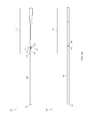
FIG. 6 is a schematic diagram illustrating a microsurgical instrument 600. In one or more embodiments, microsurgical instrument 600 may comprises a hypodermic tube 605, an actuation structure 610, and an end stick 630. Illustratively, actuation structure 610 may comprise an actuation structure distal end 611, an actuation structure proximal end 612, and a plurality of actuation arms 615. In one or more embodiments, each actuation arm 615 of a plurality of actuation arms 615 may comprise an extension mechanism 616. Illustratively, actuation structure distal end 611 may extend a decompressed distance from actuation structure proximal end 612, e.g., when actuation structure 610 comprises a decompressed actuation structure 610. In one or more embodiments, a decompressed distance may be in a range of 1.6 to 3.0 inches, e.g., a decompressed distance may be 2.25 inches. Illustratively, a decompressed distance may be less than 1.6 inches or greater than 3.0 inches. In one or more embodiments, actuation structure 610 may be manufactured from any suitable material, e.g., polymers, metals, metal alloys, etc., or from any combination of suitable materials. Illustratively, actuation structure 610 may be manufactured from a shape memory material. In one or more embodiments, actuation structure 610 may be manufactured using a selective laser sintering machine. Illustratively, actuation structure 610 may be manufactured by additive manufacturing or 3D printing. In one or more embodiments, actuation structure 610 may be manufactured from a material suitable for sterilization by a medical autoclave. Illustratively, actuation structure 610 may be manufactured from a material, e.g., Nylon, configured to withstand exposure to temperatures, pressures, and ambient conditions present in a medical autoclave without degradation. For example, actuation structure 610 may be configured to function normally after exposure in a temperature 250° F. for 15 minutes at an atmospheric pres-sure of 15 psi. In one or more embodiments, actuation structure 610 may be configured to be used in a surgical procedure and then sterilized by a medical autoclave at least three times. Illustratively, actuation structure 610 may be configured to be used in a surgical procedure and then sterilized by a medical autoclave more than three times.
In one or more embodiments, actuation structure 610 may have a density in a range of 0.02 to 0.06 pounds per cubic inch, e.g., actuation structure 610 may have a density of 0.042 pounds per cubic inch. Illustratively, actuation structure 610 may have a density less than 0.02 pounds per cubic inch or greater than 0.06 pounds per cubic inch. In one or more embodiments, actuation structure 610 may have a mass in a range of 0.005 to 0.025 pounds, e.g., actuation structure 610 may have a mass of 0.015 pounds. Illustratively, actuation structure 610 may have a mass less than 0.005 pounds or greater than 0.025 pounds. In one or more embodiments, actuation structure 610 may have a volume in a range of 0.2 to 0.5 cubic inches, e.g., actuation structure 610 may have a volume of 0.359 cubic inches. Illustratively, actuation structure 610 may have a volume less than 0.2 cubic inches or greater than 0.5 cubic inches. In one or more embodiments, actuation structure 610 may have a surface area in a range of 7.5 to 13.0 square inches, e.g., actuation structure 610 may have a surface area of 10.8 square inches. Illustratively, actuation structure 610 may have a surface area less than 7.5 square inches or greater than 13.0 square inches.
In one or more embodiments, actuation structure 610 may be configured to project actuation structure distal end 611 a first distance from actuation structure proximal end 612, e.g., when actuation structure 610 is fully decompressed. Illustratively, actuation structure 610 may comprise a shape memory material configured to project actuation structure distal end 611 a second distance from actuation structure proximal end 612, e.g., when actuation structure 610 is fully compressed. In one or more embodiments, the second distance from actuation structure proximal end 612 may be greater than the first distance from actuation structure proximal end 612. Illustratively, a compression of actuation structure 610 may be configured to gradually extend actuation structure distal end 611 relative to actuation structure proximal end 612. In one or more embodiments, actuation structure distal end 611 may extend a compressed distance from actuation structure proximal end 612, e.g., when actuation structure 610 comprises a compressed actuation structure 610. Illustratively, a compressed distance may be a distance in a range of 1.6 to 3.0 inches, e.g., a compressed distance may be 2.29 inches. In one or more embodiments, a compressed distance may be less than 1.6 inches or greater than 3.0 inches. Illustratively, a compressed distance may be in a range of 0.02 to 0.05 inches greater than a decompressed distance. In one or more embodiments, a compressed distance may be less than 0.02 inches greater than a decompressed distance. Illustratively, a compressed distance may be more than 0.05 inches greater than a decompressed distance. In one or more embodiments, a compressed distance may be in a range of 1.0 to 2.0 percent greater than a decompressed distance. Illustratively, a compressed distance may be less than 1.0 percent greater than a decompressed distance. In one or more embodiments, a compressed distance may be more than 2.0 percent greater than a decompressed distance.
Illustratively, actuation structure 610 may be compressed by an application of a force, e.g., a compressive force, to a portion of actuation structure 610. In one or more embodiments, an application of a compressive force in a range of 100 to 300 grams may be configured to compress actuation structure 610, e.g., an application of a compressive force of 200 grams may be configured to compress actuation structure 610. Illustratively, an application of a compressive force of less than 100 grams or greater than 300 grams may be configured to compress actuation structure 610. In one or more embodiments, actuation structure 610 may be compressed by an application of one or more compressive forces at one or more locations around an outer perimeter of actuation structure 610. Illustratively, the one or more locations may comprise any particular locations of a plurality of locations around an outer perimeter of actuation structure 610. For example, a surgeon may compress actuation structure 610 by squeezing actuation structure 610. Illustratively, a surgeon may compress actuation structure 610 by squeezing actuation structure 610 at any particular location of a plurality of locations around an outer perimeter of actuation structure 610. In one or more embodiments, a surgeon may compress actuation structure 610 by applying a force to a portion of actuation structure 610, e.g., when actuation structure 610 is in a first rotational orientation. Illustratively, the surgeon may then rotate actuation structure 610 and compress actuation structure 610 by applying a force to a portion of actuation structure 610, e.g., when actuation structure 610 is in a second rotational orientation. In one or more embodiments, the surgeon may then rotate actuation structure 610 and compress actuation structure 610 by applying a force to a portion of actuation structure 610, e.g., when actuation structure 610 is in a third rotational orientation. Illustratively, a surgeon may compress actuation structure 610 by applying a force to a portion of actuation structure 610, e.g., when actuation structure 610 is in any rotational orientation.
In one or more embodiments, actuation structure 610 may be compressed by an application of a compressive force to any one or more actuation arms 615 of a plurality of actuation arms 615. Illustratively, each actuation arm 615 may be connected to one or more actuation arms 615 of a plurality of actuation arms 615 wherein an actuation of a particular actuation arm 615 may be configured to actuate every actuation arm 615 of a plurality of actuation arms 615. In one or more embodiments, one or more actuation arms 615 may be configured to actuate in pairs or groups. For example, an actuation of a first actuation arm 615 may be configured to actuate a second actuation arm 615. Illustratively, a compression of actuation structure 610, e.g., due to an application of a force to a portion of actuation structure 610, may be configured to expand an extension mechanism 616 of a particular actuation arm 110. In one or more embodiments, an expansion of an extension mechanism 616 of a particular actuation arm 615 may be configured to increase a distance between a distal end and a proximal end of the particular actuation arm 615. Illustratively, an expansion of an extension mechanism 616 of a particular actuation arm 615 may be configured to expand an extension mechanism 616 of every actuation arm 615 of a plurality of actuation arms 615. In one or more embodiments, an expansion of an extension mechanism 616 of every actuation arm 615 of a plurality of actuation arms 615 may be configured to increase a distance between actuation structure distal end 611 and actuation structure proximal end 612. Illustratively, a decompression of actuation structure 610, e.g., due to a reduction of a force applied to a portion of actuation structure 610, may be configured to collapse an extension mechanism 616 of a particular actuation arm 615. In one or more embodiments, a collapse of an extension mechanism 616 of a particular actuation arm 615 may be configured to decrease a distance between a distal end and a proximal end of the particular actuation arm 615. Illustratively, a collapse of an extension mechanism 616 of a particular actuation arm 615 may be configured to collapse an extension mechanism 616 of every actuation arm 615 of a plurality of actuation arms 615. In one or more embodiments, a collapse of an extension mechanism 616 of every actuation arm 615 of a plurality of actuation arms 615 may be configured to decrease a distance between actuation structure distal end 611 and actuation structure proximal end 612.
Illustratively, end stick 630 may comprise an end stick distal end, an end stick proximal end 632, and an identification marker 635. In one or more embodiments, end stick 630 may be fixed to a portion of actuation structure 610, e.g., a portion of end stick 630 may be disposed within actuation structure 610. Illustratively, identification marker 635 may be configured to convey information about microsurgical instrument 600, e.g., identification marker 635 may comprise a color configured to correspond to a particular assembled blank 500. In one or more embodiments, identification marker 635 may comprise a color configured to correspond to a particular size of assembled blank 500. Illustratively, hypodermic tube 605 may comprise a hypodermic tube distal end 606 and a hypodermic tube proximal end. In one or more embodiments, hypodermic tube 605 may be fixed to actuation structure 610, e.g., a portion of hypodermic tube 605 may be disposed within actuation structure 610. Illustratively, assembled blank 500 may be disposed within hypodermic tube 605 and actuation structure 610, e.g., assembled blank 500 may be disposed within hypodermic tube 605 wherein first forceps jaw distal end 216 extends out from hypodermic tube distal end 606 and second forceps jaw distal end 216 extends out from hypodermic tube distal end 606. In one or more embodiments, assembled blank 500 may be fixed within actuation structure 610, e.g., fixation mechanism 645 may be configured to fix a portion of assembled blank 500 within actuation structure 610. For example, fixation mechanism 645 may comprise a setscrew. Illustratively, a portion of assembled blank 500 may be fixed within actuation structure 610 by an adhesive or any suitable fixation means, e.g., a portion of assembled blank 500 may be fixed within actuation structure 610 by a friction fit, a weld, a tie, etc.
The foregoing description has been directed to particular embodiments of this invention. It will be apparent; however, that other variations and modifications may be made to the described embodiments, with the attainment of some or all of their advantages. Specifically, it should be noted that the principles of the present invention may be implemented in any system. Furthermore, while this description has been written in terms of a surgical instrument tip, the teachings of the present invention are equally suitable to any systems where the functionality may be employed. Therefore, it is the object of the appended claims to cover all such variations and modifications as come within the true spirit and scope of the invention.

Claims (19)

What is claimed is:
1. A method of manufacturing a microsurgical instrument tip comprising:
disposing a first flat stock in a plane perpendicular to a tool electrode of an electrical discharge machine wherein the first flat stock has a first flat stock distal end, a first flat stock proximal end, a first flat stock dorsal end, and a first flat stock ventral end and wherein the first flat stock has a flat stock thickness greater than 0.005 inches;
actuating the first flat stock relative to the tool electrode;
cutting predetermined patterns into the first flat stock to form a plurality of blank tips;
separating the plurality of blank tips cut from the first flat stock, and
welding a first blank base to a first blank tip of the plurality of separated blank tips;
wherein each blank tip of the plurality of blank tips has a first forceps jaw with a first forceps jaw distal end and a first forceps jaw proximal end, a second forceps jaw with a second forceps jaw distal end and a second forceps jaw proximal end, a blank tip aperture and a blank base interface,
wherein the first forceps jaw distal end is separated from the second forceps jaw distal end by a jaw separation distance; and
wherein welding the first blank base to the first blank tip of the plurality of separated blank tips includes welding the first blank base to the blank base interface of the first blank tip.
2. The method of claim 1 further comprising:
disposing the first blank base in a hypodermic tube and an actuation structure of a microsurgical instrument.
3. The method of claim 2 wherein the actuation structure is manufactured by additive manufacturing.
4. The method of claim 2 wherein the actuation structure is manufactured by 3D printing.
5. The method of claim 2 wherein the actuation structure is manufactured from nylon.
6. The method of claim 2 wherein the actuation structure has a density in a range of 0.02 to 0.06 pounds per cubic inch.
7. The method of claim 2 wherein the actuation structure has a mass in a range of 0.005 to 0.025 pounds.
8. The method of claim 2 wherein the actuation structure has a volume in a range of 0.2 to 0.5 cubic inches.
9. The method of claim 2 wherein the actuation structure has a surface area in a range of 7.5 to 13.0 square inches.
10. The method of claim 2 further comprising:
compressing the actuation structure.
11. The method of claim 2 further comprising:
decompressing the actuation structure.
12. The method of claim 1 wherein the first flat stock is manufactured from stainless steel.
13. The method of claim 12 wherein the first flat stock is manufactured from 17-7 PH stainless steel condition C.
14. The method of claim 1 wherein the first flat stock thickness is less than 0.013 inches.
15. The method of claim 1 wherein the jaw separation distance of the first blank tip is in a range of 0.001 to 0.005 inches.
16. The method of claim 1 wherein the jaw separation distance of the first blank tip is in a range of 0.01 to 0.05 inches.
17. The method of claim 1 wherein the first flat stock thickness is in a range of 0.007 to 0.009 inches.
18. The method of claim 1 wherein the first flat stock thickness is in a range of 0.011 inches to 0.013 inches.
19. The method of claim 1 wherein the first flat stock thickness is greater than 0.013 inches.
US14/657,270 2014-04-21 2015-03-13 Method of manufacturing a microsurgical instrument tip Active 2036-11-25 US10022267B2 (en)

Priority Applications (3)

Application Number Priority Date Filing Date Title
US14/657,270 US10022267B2 (en) 2014-04-21 2015-03-13 Method of manufacturing a microsurgical instrument tip
US15/700,913 US10828191B2 (en) 2014-04-21 2017-09-11 Microsurgical instrument tip
US15/834,194 US20180098883A1 (en) 2014-04-21 2017-12-07 Microsurgical instrument tip

Applications Claiming Priority (2)

Application Number Priority Date Filing Date Title
US201461982066P 2014-04-21 2014-04-21
US14/657,270 US10022267B2 (en) 2014-04-21 2015-03-13 Method of manufacturing a microsurgical instrument tip

Related Child Applications (2)

Application Number Title Priority Date Filing Date
US15/700,913 Division US10828191B2 (en) 2014-04-21 2017-09-11 Microsurgical instrument tip
US15/834,194 Continuation US20180098883A1 (en) 2014-04-21 2017-12-07 Microsurgical instrument tip

Publications (2)

Publication Number Publication Date
US20150297278A1 US20150297278A1 (en) 2015-10-22
US10022267B2 true US10022267B2 (en) 2018-07-17

Family

ID=54320971

Family Applications (3)

Application Number Title Priority Date Filing Date
US14/657,270 Active 2036-11-25 US10022267B2 (en) 2014-04-21 2015-03-13 Method of manufacturing a microsurgical instrument tip
US15/700,913 Active 2035-05-07 US10828191B2 (en) 2014-04-21 2017-09-11 Microsurgical instrument tip
US15/834,194 Abandoned US20180098883A1 (en) 2014-04-21 2017-12-07 Microsurgical instrument tip

Family Applications After (2)

Application Number Title Priority Date Filing Date
US15/700,913 Active 2035-05-07 US10828191B2 (en) 2014-04-21 2017-09-11 Microsurgical instrument tip
US15/834,194 Abandoned US20180098883A1 (en) 2014-04-21 2017-12-07 Microsurgical instrument tip

Country Status (1)

Country Link
US (3) US10022267B2 (en)

Families Citing this family (6)

* Cited by examiner, † Cited by third party
Publication number Priority date Publication date Assignee Title
US9320534B2 (en) 2012-12-13 2016-04-26 Alcon Research, Ltd. Fine membrane forceps with integral scraping feature
US10973682B2 (en) 2014-02-24 2021-04-13 Alcon Inc. Surgical instrument with adhesion optimized edge condition
US20170079675A1 (en) * 2015-09-18 2017-03-23 Katalyst Surgical, Llc Tapered membrane removing forceps
TW201815356A (en) 2016-10-18 2018-05-01 諾華公司 Surgical instrument having a surface texture
CN106420159B (en) * 2016-12-27 2018-09-18 上海市同济医院 A kind of foreign body on cornea spade for scraping
US10849640B2 (en) 2018-05-23 2020-12-01 Katalyst Surgical, Llc Membrane aggregating forceps

Citations (32)

* Cited by examiner, † Cited by third party
Publication number Priority date Publication date Assignee Title
US1371288A (en) * 1918-10-14 1921-03-15 Wolhaupter Benjamin Process for rolling rail-anchors
US5355871A (en) 1992-09-11 1994-10-18 Dexide, Inc. Elastomeric controller for endoscopic surgical instruments
US5370658A (en) 1992-11-05 1994-12-06 Synergetics, Inc. Microsurgical instrument having dexterous handle with interchangeable instrument heads
US5647115A (en) * 1992-02-18 1997-07-15 Symbiosis Corporation Method for forming a jaw assembly for an endoscopic bioptome
US5893873A (en) 1995-10-23 1999-04-13 Johns Hopkins University Surgical instrument having a handle with a removable, rotatable tip
US5921998A (en) 1998-04-10 1999-07-13 Inami & Co., Ltd. Membrane eraser
US6488695B1 (en) 2000-08-17 2002-12-03 Alcon, Inc. Ophthalmologic surgical probe
US6575989B1 (en) 1999-09-13 2003-06-10 Synergetics, Inc. Adjustable stiffness membrane scraper
US20030171762A1 (en) 2000-08-17 2003-09-11 Forchette Mark J. Instrument dispenser
US6730076B2 (en) 2001-09-25 2004-05-04 Alcon, Inc. Fiberoptic probe tip
US6772765B2 (en) * 2002-06-12 2004-08-10 Synergistics, Inc. Surgical instrument constructed by electric discharge machining
US6863668B2 (en) 2002-08-16 2005-03-08 Edwards Lifesciences Corporation Articulation mechanism for medical devices
US20050154403A1 (en) 2004-01-14 2005-07-14 Lsi Solutions, Inc. Running stitch suturing device
US20060235382A1 (en) 2005-04-19 2006-10-19 Yoram Cohen Instrument guard and reusable medical device employing same
US20070185514A1 (en) 2006-02-06 2007-08-09 Kirchhevel G L Microsurgical instrument
US20070282348A1 (en) 2006-06-05 2007-12-06 Lumpkin Christopher F Ophthalmic microsurgical instrument
US20080183199A1 (en) 2007-01-30 2008-07-31 Jurg Attinger Membrane Scraper
US20090228066A1 (en) 2007-08-22 2009-09-10 Osaka University Intracranial electrode and method for producing same
US7632242B2 (en) 2004-12-09 2009-12-15 Boston Scientific Scimed, Inc. Catheter including a compliant balloon
US7766904B2 (en) 2003-01-31 2010-08-03 Iridex Corporation Adjustable laser probe for use in vitreoretinal surgery
US8038692B2 (en) 2006-10-31 2011-10-18 Novartis Ag Modular design for ophthalmic surgical probe
US20120116361A1 (en) 2010-11-09 2012-05-10 Hanlon Matthew A Axially Reciprocating Microsurgical Instrument with Radially Compressed Actuator Handle
US8197468B2 (en) 2003-11-13 2012-06-12 Synergetics, Inc. Surgical instrument handle with adjustable actuator position
US20130085326A1 (en) 2011-10-03 2013-04-04 Katalyst Surgical, Llc Multi-utility surgical instrument
US20130197488A1 (en) 2012-01-26 2013-08-01 Katalyst Surgical, Llc Surgical instrument sleeve
US20140066977A1 (en) 2012-08-31 2014-03-06 Katalyst Surgical, Llc Microsurgical handle and instrument
US20140121697A1 (en) 2012-10-30 2014-05-01 Katalyst Surgical, Llc Atraumatic microsurgical forceps
US20140128909A1 (en) 2012-11-07 2014-05-08 Katalyst Surgical, Llc Atraumatic microsurgical forceps
US20140142603A1 (en) 2012-11-19 2014-05-22 Katalyst Surgical, Llc Microsurgical instrument handle
US20140172010A1 (en) 2012-12-13 2014-06-19 Alcon Research, Ltd. Fine membrane forceps with integral scraping feature
US20140277110A1 (en) 2013-03-12 2014-09-18 Katalyst Surgical, Llc Membrane removing forceps
US20150088193A1 (en) 2013-09-24 2015-03-26 Katalyst Surgical, Llc Membrane removing forceps

Family Cites Families (98)

* Cited by examiner, † Cited by third party
Publication number Priority date Publication date Assignee Title
US1736731A (en) 1928-02-11 1929-11-19 Ruth W Williams Eye dropper
US2549731A (en) 1944-12-18 1951-04-17 Vincent E Wattley Flexible test prod
US3659607A (en) 1968-09-16 1972-05-02 Surgical Design Corp Method for performing surgical procedures on the eye
US4182950A (en) * 1973-10-11 1980-01-08 Boros Lawrence A Deep fill welding joint configuration and welding method
US4135868A (en) 1977-04-05 1979-01-23 Herbert Schainholz Supports for instrument sterilization
US4504264A (en) 1982-09-24 1985-03-12 Kelman Charles D Apparatus for and method of removal of material using ultrasonic vibraton
US4553957A (en) 1983-05-03 1985-11-19 Alcon Laboratories, Inc. Irrigation/aspiration handpiece
US4541992A (en) 1983-08-10 1985-09-17 Hu-Friedy Manufacturing Co. Apparatus for organizing, sterilizing, and maintaining medical/dental instruments
US4938214A (en) * 1984-09-10 1990-07-03 Micrins Surgical Instruments, Ltd. Hand held surgical tool
US4610252A (en) 1984-10-15 1986-09-09 Catalano J Denis Dual muscle clamp
US4739761A (en) 1986-06-26 1988-04-26 Grandon Stanley C Cornea marker
US4706666A (en) 1987-03-03 1987-11-17 Sheets John H Positioning implement for intraocular lens
US4798292A (en) 1987-04-03 1989-01-17 Biomedical Laser Industries Sterilization, storage, and presentation container for surgical instruments
US4761028A (en) * 1987-05-11 1988-08-02 Andrew Tool Company Single-piece tweezers
US4959199A (en) 1988-02-19 1990-09-25 Brewer Charles A Autoclavable modular cassette and tray for holding dental instruments
US6099550A (en) 1989-12-05 2000-08-08 Yoon; Inbae Surgical instrument having jaws and an operating channel and method for use thereof
US5215726A (en) 1991-07-17 1993-06-01 Hu-Friedy Mfg. Co., Inc. Two-tiered sterilization and storage cassette
US5294413A (en) 1991-07-17 1994-03-15 Hu-Friedy Mfg. Co., Inc. Sterilization and storage cassette
US5286255A (en) 1991-07-29 1994-02-15 Linvatec Corporation Surgical forceps
US5190050A (en) 1991-11-08 1993-03-02 Electro-Catheter Corporation Tip deflectable steerable catheter
US5636639A (en) 1992-02-18 1997-06-10 Symbiosis Corporation Endoscopic multiple sample bioptome with enhanced biting action
US5222973A (en) 1992-03-09 1993-06-29 Sharpe Endosurgical Corporation Endoscopic grasping tool surgical instrument
US5384103A (en) 1992-03-17 1995-01-24 Micromedics, Inc. Instrument tray
US5318589A (en) 1992-04-15 1994-06-07 Microsurge, Inc. Surgical instrument for endoscopic surgery
US5227313A (en) 1992-07-24 1993-07-13 Eastman Kodak Company Process for making backside illuminated image sensors
US5346677A (en) 1992-09-04 1994-09-13 Risk William B Instrument cassette
CA2106126A1 (en) 1992-09-23 1994-03-24 Ian M. Scott Bipolar surgical instruments
US5792165A (en) 1993-07-21 1998-08-11 Charles H. Klieman Endoscopic instrument with detachable end effector
US5810811A (en) 1993-07-22 1998-09-22 Ethicon Endo-Surgery, Inc. Electrosurgical hemostatic device
US5425730A (en) 1994-02-16 1995-06-20 Luloh; K. P. Illumination cannula system for vitreous surgery
US5415645A (en) 1994-04-29 1995-05-16 Friend; John M. Retractable sheath for hypodermic needle
US5451230A (en) 1994-10-11 1995-09-19 Steinert; Roger F. Cataract disassembly
EP0804253B1 (en) 1995-01-20 2001-08-16 Poly-Vac, Incorporated Sterilization and storage container tray for surgical instruments
US5601581A (en) 1995-05-19 1997-02-11 General Surgical Innovations, Inc. Methods and devices for blood vessel harvesting
US5695514A (en) 1995-07-13 1997-12-09 Guidant Corporation Method and apparatus for harvesting blood vessels
DE69632202T2 (en) 1995-07-28 2005-04-21 Cardiotronics Int Inc ELECTRICAL DISPOSABLE DEVICE
US5893877A (en) 1996-04-10 1999-04-13 Synergetics, Inc. Surgical instrument with offset handle
USD393067S (en) 1996-08-27 1998-03-31 Valleylab Inc. Electrosurgical pencil
US5814043A (en) 1996-09-06 1998-09-29 Mentor Ophthalmics, Inc. Bipolar electrosurgical device
USD393715S (en) 1996-09-13 1998-04-21 Hgm, Inc. Optical fiber handpiece
US5759502A (en) 1997-01-31 1998-06-02 Sterilization Cassette Systems, Inc. Instrument cassette having a mechanism to prevent lateral movement of an instrument support relative to an instrument support holder
US5851197A (en) 1997-02-05 1998-12-22 Minimed Inc. Injector for a subcutaneous infusion set
CA2252798A1 (en) 1997-02-28 1998-09-03 Ethicon Endo-Surgery, Inc. Preventing reuse of surgical devices
US6277100B1 (en) 1997-07-17 2001-08-21 Medical Components, Inc. Catheter guide wire introducing device and method
US5913422A (en) 1997-09-04 1999-06-22 Poly Vac, Inc. Surgical tool sterilization and storage container system
US6159162A (en) 1998-05-04 2000-12-12 Lsvp International, Inc. Biopsy apparatus
US6419675B1 (en) 1999-09-03 2002-07-16 Conmed Corporation Electrosurgical coagulating and cutting instrument
US6575919B1 (en) 1999-10-19 2003-06-10 Kyphon Inc. Hand-held instruments that access interior body regions
US6616683B1 (en) 2000-05-02 2003-09-09 Duke University Method of making miniaturized surgical forceps
JP2002117918A (en) 2000-10-11 2002-04-19 Sumitomo Wiring Syst Ltd Connector for grounding
US6800076B2 (en) 2000-10-18 2004-10-05 Retinalabs, Inc. Soft tip cannula and methods for use thereof
US6855156B2 (en) 2000-10-19 2005-02-15 Grieshaber & Co. Ag Schaffhausen Ophthalmic microsurgical instrument
USD465279S1 (en) 2000-10-26 2002-11-05 Grieshaber & Co. Ag Schaffhausen Ophthalmologic surgical instrument
US6451037B1 (en) 2000-11-22 2002-09-17 Scimed Life Systems, Inc. Expandable atherectomy burr with metal reinforcement
US6592603B2 (en) * 2000-12-15 2003-07-15 Michael Lasner Manually adjustable scissors or forceps
US6875165B2 (en) 2001-02-22 2005-04-05 Retinalabs, Inc. Method of radiation delivery to the eye
WO2002074369A1 (en) 2001-03-20 2002-09-26 Disetronic Licensing Ag Needle protective covering
USD453222S1 (en) 2001-04-30 2002-01-29 Jon C. Garito Electrosurgical handpiece
US6926728B2 (en) 2001-07-18 2005-08-09 St. Francis Medical Technologies, Inc. Curved dilator and method
US6749601B2 (en) 2001-08-03 2004-06-15 Scimed Life Systems, Inc. Protective sleeve for an endoscopic instrument and related method of use
US6945984B2 (en) 2001-08-23 2005-09-20 Alcon Grieshaber Ag Micro surgical instrument
US6572565B2 (en) 2001-10-10 2003-06-03 Maxxon, Inc. Blood sampling assembly with a retractable needle
US6908476B2 (en) 2001-12-21 2005-06-21 Alcon Grieshaber Ag Micro surgical cutting instrument configured as scissors
EP2204210B1 (en) 2002-06-20 2012-02-29 Becton, Dickinson and Company Catheter and introducer needle assembly with needle shield
US8043303B2 (en) 2002-10-04 2011-10-25 Cook Medical Technologies Llc Handle for interchangeable medical device
US7338494B2 (en) 2003-08-19 2008-03-04 Synthes (U.S.A.) Spring-loaded awl
US7276074B2 (en) 2004-01-21 2007-10-02 Medtronic Xomed, Inc. Angled tissue cutting instrument having variably positionable cutting window, indexing tool for use therewith and method of variably positioning a cutting window of an angled tissue cutting instrument
US20050245950A1 (en) 2004-04-29 2005-11-03 Kozlowski Martin J Method and apparatus to mark an incision
US7438717B2 (en) 2004-08-04 2008-10-21 James Tylke Anesthesia intubating forceps
US8262682B2 (en) 2004-08-10 2012-09-11 Asico Llc Nucleus chopper and splitter
US7731728B2 (en) 2004-11-30 2010-06-08 Glaser Bert M Internal limiting membrane rake
KR100592944B1 (en) 2005-03-22 2006-06-26 문현준 Multi-ringed separator for tubular organs
JP5140800B2 (en) 2005-05-12 2013-02-13 アルスタシス,インコーポレイテッド Access and occlusion devices
US7544336B2 (en) 2005-11-07 2009-06-09 Andrew Powell Sterilization tray with base and elastomeric lid
AR058556A1 (en) 2005-12-16 2008-02-13 Alcon Inc CANULA FOR LIGHTED INFUSION
USD565733S1 (en) 2006-03-08 2008-04-01 Jean-Marie Andre Instrument for ocular surgery
DE102006040529A1 (en) 2006-08-30 2008-03-13 Paul Peschke Gmbh Surgical grasping forceps
WO2008085966A2 (en) * 2007-01-09 2008-07-17 Becton, Dickinson And Company Insertion tool and packaging for ocular implant and method for using same
US20080195135A1 (en) 2007-02-12 2008-08-14 Alcon, Inc. Surgical Probe
AU2008239408B2 (en) 2007-04-11 2013-07-04 Covidien Lp Endoscopic/laparoscopic introducer sleeve
USD625412S1 (en) 2007-05-04 2010-10-12 Garito Jon C Electrosurgical handpiece with dome
KR20100062991A (en) 2007-07-10 2010-06-10 우노메디컬 에이/에스 Inserter having two springs
WO2009042874A1 (en) 2007-09-27 2009-04-02 Tyco Healthcare Group Lp I.v. catheter assembly and needle safety device
DE102007052185A1 (en) 2007-10-25 2009-04-30 Karl Storz Gmbh & Co. Kg Suture attachment for a surgical suture instrument
US20110015669A1 (en) 2007-11-08 2011-01-20 Corcosteugi Borja F Forceps
US20090318856A1 (en) 2008-06-18 2009-12-24 Glaser Bert M Sampling Ocular Fluid
JP2010040696A (en) * 2008-08-04 2010-02-18 Hitachi Cable Ltd Substrate for epitaxial growth
US7959556B2 (en) * 2009-08-27 2011-06-14 Coloplast A/S Penile prosthesis cap, assembly, and implantation tool
WO2011037866A1 (en) 2009-09-22 2011-03-31 Cook Incorporated Vessel closure device
WO2012082751A1 (en) 2010-12-13 2012-06-21 I-Tech Development Company Distally actuated surgical instrument
US8475479B2 (en) 2011-01-21 2013-07-02 Alcon Research, Ltd. Surgical probe
US9089399B2 (en) 2011-09-17 2015-07-28 Katalyst Surgical, Llc Steerable laser probe
US20140012314A1 (en) 2012-06-29 2014-01-09 Invivo Therapeutics Corporation Cupped forceps
US20140135820A1 (en) 2012-11-13 2014-05-15 Alcon Research, Ltd. Disposable capsulorhexis forceps
US20140163363A1 (en) 2012-12-12 2014-06-12 Katalyst Surgical, Llc Membrane visualization instrument
US9427251B2 (en) 2013-03-13 2016-08-30 Covidien Lp Saber tooth harvester
US20150173944A1 (en) 2013-12-23 2015-06-25 Novartis Ag Systems and methods for attaching a surgical instrument tip
WO2017066026A1 (en) 2015-10-12 2017-04-20 Katalyst Surgical, Llc Instrument handle and replaceable tip

Patent Citations (32)

* Cited by examiner, † Cited by third party
Publication number Priority date Publication date Assignee Title
US1371288A (en) * 1918-10-14 1921-03-15 Wolhaupter Benjamin Process for rolling rail-anchors
US5647115A (en) * 1992-02-18 1997-07-15 Symbiosis Corporation Method for forming a jaw assembly for an endoscopic bioptome
US5355871A (en) 1992-09-11 1994-10-18 Dexide, Inc. Elastomeric controller for endoscopic surgical instruments
US5370658A (en) 1992-11-05 1994-12-06 Synergetics, Inc. Microsurgical instrument having dexterous handle with interchangeable instrument heads
US5893873A (en) 1995-10-23 1999-04-13 Johns Hopkins University Surgical instrument having a handle with a removable, rotatable tip
US5921998A (en) 1998-04-10 1999-07-13 Inami & Co., Ltd. Membrane eraser
US6575989B1 (en) 1999-09-13 2003-06-10 Synergetics, Inc. Adjustable stiffness membrane scraper
US6488695B1 (en) 2000-08-17 2002-12-03 Alcon, Inc. Ophthalmologic surgical probe
US20030171762A1 (en) 2000-08-17 2003-09-11 Forchette Mark J. Instrument dispenser
US6730076B2 (en) 2001-09-25 2004-05-04 Alcon, Inc. Fiberoptic probe tip
US6772765B2 (en) * 2002-06-12 2004-08-10 Synergistics, Inc. Surgical instrument constructed by electric discharge machining
US6863668B2 (en) 2002-08-16 2005-03-08 Edwards Lifesciences Corporation Articulation mechanism for medical devices
US7766904B2 (en) 2003-01-31 2010-08-03 Iridex Corporation Adjustable laser probe for use in vitreoretinal surgery
US8197468B2 (en) 2003-11-13 2012-06-12 Synergetics, Inc. Surgical instrument handle with adjustable actuator position
US20050154403A1 (en) 2004-01-14 2005-07-14 Lsi Solutions, Inc. Running stitch suturing device
US7632242B2 (en) 2004-12-09 2009-12-15 Boston Scientific Scimed, Inc. Catheter including a compliant balloon
US20060235382A1 (en) 2005-04-19 2006-10-19 Yoram Cohen Instrument guard and reusable medical device employing same
US20070185514A1 (en) 2006-02-06 2007-08-09 Kirchhevel G L Microsurgical instrument
US20070282348A1 (en) 2006-06-05 2007-12-06 Lumpkin Christopher F Ophthalmic microsurgical instrument
US8038692B2 (en) 2006-10-31 2011-10-18 Novartis Ag Modular design for ophthalmic surgical probe
US20080183199A1 (en) 2007-01-30 2008-07-31 Jurg Attinger Membrane Scraper
US20090228066A1 (en) 2007-08-22 2009-09-10 Osaka University Intracranial electrode and method for producing same
US20120116361A1 (en) 2010-11-09 2012-05-10 Hanlon Matthew A Axially Reciprocating Microsurgical Instrument with Radially Compressed Actuator Handle
US20130085326A1 (en) 2011-10-03 2013-04-04 Katalyst Surgical, Llc Multi-utility surgical instrument
US20130197488A1 (en) 2012-01-26 2013-08-01 Katalyst Surgical, Llc Surgical instrument sleeve
US20140066977A1 (en) 2012-08-31 2014-03-06 Katalyst Surgical, Llc Microsurgical handle and instrument
US20140121697A1 (en) 2012-10-30 2014-05-01 Katalyst Surgical, Llc Atraumatic microsurgical forceps
US20140128909A1 (en) 2012-11-07 2014-05-08 Katalyst Surgical, Llc Atraumatic microsurgical forceps
US20140142603A1 (en) 2012-11-19 2014-05-22 Katalyst Surgical, Llc Microsurgical instrument handle
US20140172010A1 (en) 2012-12-13 2014-06-19 Alcon Research, Ltd. Fine membrane forceps with integral scraping feature
US20140277110A1 (en) 2013-03-12 2014-09-18 Katalyst Surgical, Llc Membrane removing forceps
US20150088193A1 (en) 2013-09-24 2015-03-26 Katalyst Surgical, Llc Membrane removing forceps

Non-Patent Citations (1)

* Cited by examiner, † Cited by third party
Title
Steve Charles, Techniques and tools for dissection of epiretinal membranes, Graefe' Arch Clin Exp Ophthalmol, 241:347-352, 2003.

Also Published As

Publication number Publication date
US20170367884A1 (en) 2017-12-28
US10828191B2 (en) 2020-11-10
US20180098883A1 (en) 2018-04-12
US20150297278A1 (en) 2015-10-22

Similar Documents

Publication Publication Date Title
US10828191B2 (en) Microsurgical instrument tip
US10413445B2 (en) Atraumatic microsurgical forceps
US20200405337A1 (en) Membrane Removing Instrument
US9173772B1 (en) Microsurgical handle and instrument
US11571211B2 (en) Hermetic force sensors for surgical devices
US10806508B2 (en) Method for manufacturing an electrode assembly configured for use with an electrosurgical instrument
US10299816B2 (en) Microsurgical handle and instrument
US20150088193A1 (en) Membrane removing forceps
US9247951B1 (en) Microsurgical handle and instrument
US20170086871A1 (en) Asymmetric membrane removing forceps
US20170079675A1 (en) Tapered membrane removing forceps
US10959800B2 (en) Force sensors for surgical devices to prevent ingress of fluids
US20170100114A1 (en) Instrument handle and replaceable tip
WO2015199931A3 (en) Lockout engagement features for surgical stapler
JP2015533092A5 (en)
US11160935B2 (en) Reusable instrument handle with single-use tip
US11752034B2 (en) Medical device and methods of manufacturing thereof
US10849640B2 (en) Membrane aggregating forceps
CN106255468B (en) Surgical clip
US20210069788A1 (en) Method of joining a shape-memory metal to a non-shape-memory metal with ultrasonic additive manufacturing
AU2022296032A1 (en) Method of manufacturing one or more sharp bodies by wire electro-erosion, semi- finished product, fixture, and method of manufacturing a surgical cutting instrument for robotic microsurgery by wire electro-erosion

Legal Events

Date Code Title Description
AS Assignment

Owner name: KATALYST SURGICAL, LLC, MISSOURI

Free format text: ASSIGNMENT OF ASSIGNORS INTEREST;ASSIGNOR:SCHELLER, GREGG D;REEL/FRAME:035163/0004

Effective date: 20150313

STCF Information on status: patent grant

Free format text: PATENTED CASE

MAFP Maintenance fee payment

Free format text: PAYMENT OF MAINTENANCE FEE, 4TH YR, SMALL ENTITY (ORIGINAL EVENT CODE: M2551); ENTITY STATUS OF PATENT OWNER: SMALL ENTITY

Year of fee payment: 4

FEPP Fee payment procedure

Free format text: ENTITY STATUS SET TO UNDISCOUNTED (ORIGINAL EVENT CODE: BIG.); ENTITY STATUS OF PATENT OWNER: LARGE ENTITY