KR930001194B1 - Receiver - Google Patents
Receiver Download PDFInfo
- Publication number
- KR930001194B1 KR930001194B1 KR1019890701427A KR890701427A KR930001194B1 KR 930001194 B1 KR930001194 B1 KR 930001194B1 KR 1019890701427 A KR1019890701427 A KR 1019890701427A KR 890701427 A KR890701427 A KR 890701427A KR 930001194 B1 KR930001194 B1 KR 930001194B1
- Authority
- KR
- South Korea
- Prior art keywords
- signal
- input
- output
- band
- mixer
- Prior art date
Links
Images


Classifications
-
- H—ELECTRICITY
- H04—ELECTRIC COMMUNICATION TECHNIQUE
- H04B—TRANSMISSION
- H04B1/00—Details of transmission systems, not covered by a single one of groups H04B3/00 - H04B13/00; Details of transmission systems not characterised by the medium used for transmission
- H04B1/06—Receivers
- H04B1/16—Circuits
- H04B1/26—Circuits for superheterodyne receivers
-
- H—ELECTRICITY
- H03—ELECTRONIC CIRCUITRY
- H03D—DEMODULATION OR TRANSFERENCE OF MODULATION FROM ONE CARRIER TO ANOTHER
- H03D7/00—Transference of modulation from one carrier to another, e.g. frequency-changing
- H03D7/16—Multiple-frequency-changing
- H03D7/161—Multiple-frequency-changing all the frequency changers being connected in cascade
-
- H—ELECTRICITY
- H04—ELECTRIC COMMUNICATION TECHNIQUE
- H04N—PICTORIAL COMMUNICATION, e.g. TELEVISION
- H04N7/00—Television systems
- H04N7/20—Adaptations for transmission via a GHz frequency band, e.g. via satellite
Landscapes
- Engineering & Computer Science (AREA)
- Signal Processing (AREA)
- Power Engineering (AREA)
- Physics & Mathematics (AREA)
- Astronomy & Astrophysics (AREA)
- General Physics & Mathematics (AREA)
- Multimedia (AREA)
- Computer Networks & Wireless Communication (AREA)
- Superheterodyne Receivers (AREA)
- Input Circuits Of Receivers And Coupling Of Receivers And Audio Equipment (AREA)
Abstract
내용 없음.No content.
Description
[발명의 명칭][Name of invention]
수신장치Receiver
[도면의 간단한 설명][Brief Description of Drawings]
제1도는 종래 수신장치의 구성을 나타낸 블록선도이고,1 is a block diagram showing the configuration of a conventional receiver,
제2도는 본 발명의 수신장치를 구체화 한 블록선도이며,2 is a block diagram embodying the receiving apparatus of the present invention,
제3도는 제2도의 주요 부분의 블록선도이다.3 is a block diagram of the main part of FIG.
[발명의 상세한 설명]Detailed description of the invention
[기술분야][Technical Field]
본 발명은 케이블로 전송되는 위성방송(衛星放送) 프로그램을 수신하기 위한 CATV변환기(cable television converter), 텔레비젼 동조기(tuner)등과 같은 수신장치에 관한 것이다.BACKGROUND OF THE INVENTION 1. Field of the Invention The present invention relates to a receiver such as a CATV converter, a television tuner, and the like for receiving a satellite broadcast program transmitted by cable.
[배경기술][Background]
근년에 뉴메디아(new media)대두에 의하여 위성방송이나, CATV등이 일반화 되어 있다. 거기서, 위성방송을 수신하는 시스템(system)으로는 각 가정에 포물선형 안테나를 설치하여 수신한 신호를, 예를들면 4GHZ대(帶)의 신호를 ″BS변환기(Broadeast Satellite Converter)″로 불리는 주파수 변환기에 의하여 1.0GHZ~1.3GHZ대의 중간-주파수신호(BS-IF(internediate Frequency)신호)로 변환하여서 옥내에 인입(lead in), BS동조기로 수신하는 것이 일반적이다. CATV가 발전하여 온 것에 의하여 텔레비젼 밴드(band)중 슈퍼하이 밴드(supperhigh band) 또는 UHF밴드를 BS1채널당 수(數)채널분을 사용해서 위성방송의 FM신호를 전송하는 것이 실시되고 이다. 이 경우에, 수신하는 시스템으로는 케이블신호를 업-콘버터(up-converter)를 사용하여 BS-IF신호로 변환하고, 그 출력을 BS동조기에 공급하여 수신하는 것이 일반적이다.In recent years, new media soybeans have become commonplace, such as satellite broadcasting and CATV. As a system for receiving satellite broadcasts, a signal obtained by installing a parabolic antenna in each home, for example, a signal of 4 GHz Z band, is called a `` Broadeast Satellite Converter ''. In general, the frequency converter converts the intermediate frequency signal (BS-IF (internediate frequency signal) in the range of 1.0GH Z to 1.3GH Z ) to be received indoors and received by the BS tuner. It is being carried by the CATV developed using the TV band (band) super high-band (supperhigh band) or a UHF band of the BS 1 per channel (數) channel minutes by being turned on to transmit an FM signal of a satellite broadcast. In this case, it is common for a receiving system to convert a cable signal into a BS-IF signal using an up-converter, and supply the output to a BS tuner to receive the signal.
이하, 도면을 참조하면서 상술한 바와같은 종래의 수신장치에 대하여 설명할 것이다.Hereinafter, a conventional receiver as described above will be described with reference to the drawings.
제1도는 종래의 케이블에 의한 위성방송의 수신시스템이다. 제1도에 있어서(1)은 CATV장비, (21)은 CATV장비 (1)로부터 출력되는 CATV신호를 주파수 변환하는 CATV변환기, (3)은 TV세트, (4)는 CATV장비(1)로부터 출력되는 CATV신호를 주파수 변환하는 BS업-콘버터(BS up-converter), (5)는 BS동조기로서, 그 출력신호는 TV세트(3)에 공급된다.1 is a conventional reception system for satellite broadcasting by cable. In Fig. 1, reference numeral 1 denotes a CATV device, 21 a CATV converter for frequency converting a CATV signal output from the CATV device 1, 3 a TV set, and 4 a CATV device 1 from the BS up-converter (5) for frequency converting the output CATV signal is a BS tuner, the output signal of which is supplied to TV set (3).
이상과같이 구성된 수신장치에 대해서, 이하 그 동작에 대하여 설명하면 다음과 같다. 제1도에 있어서, CATV장비(1)에 의하여 전송된 케이블 신호중 일반적으로 6MHZ대 신호는 CATV변환기(21)로 일정의 RF채널 신호에 주파수가 변환되어 TV세트(3)에 입력된다. 한편, CATV장비(1)에서 슈퍼하이 밴드 또는 UHF밴드로 변환된 BS-IF신호는 BS업-콘버터(4)에 의하여 1.0GHZ~1.3GHZ대에 주파수 변환되어 BS동조기(5)에 입력된다. BS동조기(5)에 있어서, UHF 13채널로 변환되거나, 또는 오디오신호ㆍ비디오신호로서 출력되어 TV세트(3)에 입력된다. 모든 밴드 동조기형 수신기의 경우는 CATV변환기(21)를 생략한다.The following describes the operation of the receiving device configured as described above. In FIG. 1, generally 6 MH Z band signals among the cable signals transmitted by the CATV equipment 1 are converted into a predetermined RF channel signal by the
그러나, 상기한 바와같이 슈퍼하이 밴드나 UHF밴드로 변환된 BS-IF신호를 수신하기 위하여, 별도로 BS업-콘버터(4)가 필요하며 대폭 가격을 상승시키는 문제점을 가져온다.However, in order to receive the BS-IF signal converted into the super high band or the UHF band as described above, the BS up-
그러므로, 본 발명은 별도 BS업-콘버터를 사용할 필요가 없으므로 대폭가격이 저렴한 수신장치를 제공하는 것을 목적으로 한다.Therefore, an object of the present invention is to provide a receiver which is significantly inexpensive since there is no need to use a separate BS up-converter.
[발명의 개시][Initiation of invention]
이 목적을 달성하기 위하여, 본 발명의 수신장치는 제1주파수 변환부와 제2주파수 변환부를 구비한 이중 슈퍼형의 변환기와 동조기를 사용하여, 제1주파수 변환부의 출력단에 BS동조기에 입력하기 위한 변환기 단자를 설치하고, UHF밴드 또는 슈퍼하이 밴드로 변환된 BS신호를 케이블 개재하여 제1주파수 변환부로 입력하고, 주파수 변환 처리하여서 그 변환기 출력단자로부터 BS-IF신호를 끄집어내서 별도 BS업-콘버터를 사용하지 않고 BS-IF신호를 BS동조기에 공급하도록 되어있다.In order to achieve this object, the receiver of the present invention uses a dual super converter and a tuner having a first frequency converter and a second frequency converter, and a converter for inputting the BS tuner to the output of the first frequency converter. A terminal is installed, and the BS signal converted into UHF band or super high band is input to the first frequency converter through a cable, the frequency conversion process is performed, and the BS-IF signal is taken out from the converter output terminal. It supplies BS-IF signal to BS tuner without using.
이러한 구성에 의하여, 변환기 또는 동조기내에 업-콘버션(up-conversion)기능을 가질 수가 있고, 별도 BS업-콘버터를 추가할 필요가 없기 때문에, 구성의 간단화를 도모하므로 대폭 가격을 저렴하게 할 수 있다.With this configuration, it is possible to have an up-conversion function in the converter or the tuner, and there is no need to add a separate BS up-converter, so that the configuration can be simplified, thereby greatly reducing the price. Can be.
[발명의 실시하기 위한 최선의 형태]Best Mode for Carrying Out the Invention
이하, 본 발명의 실시예를 도면을 참조하여 설명한다.Hereinafter, embodiments of the present invention will be described with reference to the drawings.
제2도는 본 발명에 따른 수신장치를 구체화 한 전체 구성을 나타낸 것이다. 제2도에 있어서, (1)은 CATV장비로서, 6MHZ대의 텔레비젼신호와 위성방송을 수신하여 수채널분을 사용하여서 슈퍼하이 밴드또는 UHF밴드로 변환된 BS-IF신호를 각각 출력한다. (2)는 이중 슈퍼형의 변환기로서 CATV장비(1)에서 출력신호를 입력한다. (3)은 텔레비젼 세트, (5)는 1.0~3.0GHZ대의 신호를 입력하는 BS동조기이다. 텔레비젼세트(3)가 CATV수신 가능한 이중 슈퍼형의 동조기를 내장하고 있는 경우에 변환기(2)는 생략된다.Figure 2 shows the overall configuration of the receiver according to the present invention. The method of
이상과 같이 구성된 수신장치에 대해서 이하 그 동작에 대해서 설명한다. 변환기(2)또는 텔레비젼 세트(3)에 내장되는 CATV수신 가능한 이중 슈퍼형의 동조기에는 변환기 출력단자가 설치되어 있다. CATV장비(1)로 부터 출력되고, 슈퍼하이 밴드 또는 UHF밴드로 변환된 BS-IF신호를 상기 이중 슈퍼형의 변환기(2)또는 동조기에 의하여 1.0~1.3GHZ로 주파수 변환하여서 BS동조기(5)에 입력하고, 여기서 얻은 오디오신호ㆍ비디오신호를 텔레비젼 세트(3)의 각각의 입력단자에 입력하는 것이다.The operation of the receiver configured as described above will be described below. The converter output terminal is provided in the CATV-receiving dual super type tuner incorporated in the
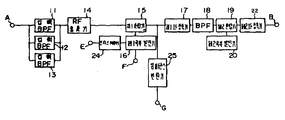
다음, 제3도에 대하여 설명한다. 제3도는 제2도에 표시된 이중 슈퍼방식으로 구성한 변환기(2) 또는 TV세트(3)에 내장되는 CATV수신 가능한 동조기부의 구성을 나타낸 것이다. 이하는 이중 슈퍼동조기의 구성을 표시하였지만, 변환기에 있어서도 기본적으로 같은 구성이 된다. 제3도에 있어서 (11)~(13)은 각각 통과 주파수의 다른 입력 BPF(Band-pass Filter)(14)는 광대역 RF증폭기(Radio Frequency Amplifier), (15)는 제1혼합기, (16)은 주파수 가변의 제1국부발진기, (17)은 제1IF증폭기, (18)은 BPF, (19)는 제2혼합기, (20)은 발진주파수가 고정의 제2국부발진기, (22)는 제2IF증폭기, (24)는 프리스케일러(prescaler), (25)는 임피던스 변환기이다.Next, FIG. 3 is explained. FIG. 3 shows the structure of the CATV receiving tuner unit incorporated in the
이상과같이 구성된 동조기부에 대하여 이하 그 동작을 설명한다. 제3도에 있어서, (11),(12)와 (13)은 각 밴드(예를들면, VHF저밴드 VL과 중밴드, VHF고밴드 VH와 슈퍼하이 밴드와, UHF밴드)와 같이 설치된 입력 BPF이다. 단자(A)에 의하여 입력되고, 이 입력 BPF(11), (12)와 (13)를 통과한 신호는 광대역 RF증폭기(14)로 증폭되고 제1혼합기(15)에 입력된다. 이 광대역 RF증폭기(14)의 출력신호는 제1혼합기 (15)에 있어서 제1국부발진기(16)의 제1국부발진신호와 혼합되어 신호들 사이의 다른 성분 제1IF신호로서 나오게 된다. 제1IF산호는 제1IF증폭기(17)로 증폭되고, BPF(18)로 제1IF신호만 선택되어 제2혼합기(19)에 입력된다. 이 제1IF신호는 제2국부발진기(20)의 제2국부발진신호와 제2혼합기(19)에 있어서 혼합되고, 신호들 사이의 다른 성분이 제2IF신호는 예를들면 58.75MHZ의 중간주파수 신호로서 나오게 된다. 제2IF신호는 제2IF증폭기(22)를 통과하여 제2IF출력신호로서 단자(B)에 출력된다. 제1국부발진기(16)에는 단자(F)에 의하여 동조용 전압이 공급되고, 또는 프리스캘러 (14)에 의하여 제1국부발진기(16)의 국부발진신호를 분주(分周)하고, 그 출력을 단자(E)에 의하여 선택회로에 공급된다. 이상의 구성은 이중 슈퍼방식 동조기 도는 변환기의 구성이고, CATV등에서 다중 채널수신과 광대역 수신에 유리한 시스템이다.The operation of the tuning unit configured as described above will be described below. In FIG. 3, (11), (12) and (13) are the same as each band (e.g., VHF low band V L and mid band, VHF high band V H and super high band and UHF band). Input BPF installed. The signal inputted by the terminal A and passed through these
다음에, 단자(A)에 UHF대로 변환된 BS-IF신호가 입력된 경우를 생각하면, 예를들면 주파수 관계는 다음과 같다.Next, considering the case where the BS-IF signal converted to the UHF band is input to the terminal A, for example, the frequency relationship is as follows.

즉, 이러한 경우 제1국부발진주파수를 1801.5MHZ로 설정하면 제1혼합기(15)의 출력신호로서 업-콘버터 된 BS-IF신호는 다시 얻을 수 있게 된다. 또한, BS-IF신호가 슈퍼하이 밴드로 변환되는 경우에는 제1국부발진주파수는 약 1500MHZ로 된다.That is, in this case, the first by setting the local oscillation frequency to 1801.5MH Z as an output signal of the first up mixer (15), - the converter BS-IF signal can be obtained again. On the contrary, if the BS-IF signal is converted to a super high band, the first local oscillation frequency is approximately 1500MH Z.
한편, 통상의 VHF저밴드, VHF고밴드와 UHF밴드의 일부의 신호를 수신하는 이중 슈퍼 동조기에서의 제1IF신호의 주파수를 일례로서 950MHz로 선정하면 필요한 제1국부발진주파수의 범위는 1040MHz~1720MHz로 되어 상술한 UHF또는 슈퍼하이 밴드의 어느 밴드로 전송된 경우라고 CATV채널에 필요한 국부발진주파수의 가변범위내에 있다. 또한 , 가열 NTSC방식의 텔레비젼 신호와 BS-IF신호의 자스트 로우칼 점(Just local point)이 다를 경우는 선국(station-selection)프로그램중에 추가하면 좋다.On the other hand, if the frequency of the first IF signal in the double super tuner that receives a part of the signals of the normal VHF low band, VHF high band and UHF band is set to 950 MHz as an example, the required first local oscillation frequency range is 1040 MHz to 1720 MHz. In this case, it is within the variable range of the local oscillation frequency required for the CATV channel when it is transmitted in any of the above-mentioned UHF or super high bands. If the just local point of the television signal of the heated NTSC system and the BS-IF signal is different, it may be added to the station-selection program.
이와같이, 단자(A) 로부터의 입력신호는 슈퍼하이 밴드시에는 입력 BPF(12)를 UHF밴드시에는 입력 BPF(13)를 각각 통과하고, RF증폭기(14)를 통하여 제1혼합기 (15)에 입력하고, 상기 제1국부발진신호와 혼합되어 혼합기 출력으로서 주파수 변환된 정규의 BS-IF신호(1.0~1.3GHz)가 나타난다. 이 BS-IF신호는 임피던스 변환기 (25)를 통하여 단자(G)에 출력되어 케이블등에서 BS동조기(5)의 IF입력단자에 입력되는 것으로 된다. 또한, 제1혼합기(15)의 출력 임피던스가 약 75![]()
![]()
이상과 같이, 본 실시예에 의하면, 이중 슈퍼방식의 변환기(2) 또는 같은 방식의 동조기를 채용하고, 제1혼합기(15)의 출력측에 블록변환 출력단자(G)를 설치하므로써 케이블 전송된 BS-IF신호를 업-콘버터를 사용하지 않고 수신 가능한 시스템을 만들어 낼 수가 있다.As described above, according to the present embodiment, the BS is cabled by adopting the dual
[산업상의 이용 가능성][Industry availability]
이상과 같이 본 발명은 케이블 전송된 BS-IF신호를 수신하기 위한 변환기 또는 동조기로서 이중 슈퍼방식을 채용하고, 제1혼합기의 출력단에 변환기 출력단자를 설치하므로써 종래와 같이 외부에 업-콘버터를 부착할 필요가 없으므로 구성을 현저하게 간단화 할 수 있고, 그리고 저렴하게 소형의 수신 시스템으로 할 수가 있어 그 실용적인 효과는 대단한 것이다.As described above, the present invention adopts a dual super system as a converter or a tuner for receiving a cable-transmitted BS-IF signal, and attaches an up-converter to the outside as in the prior art by installing a converter output terminal at an output terminal of the first mixer. Since there is no need to do so, the configuration can be significantly simplified, and a compact reception system can be made at a low cost, and the practical effect is enormous.
Claims (2)
Applications Claiming Priority (4)
| Application Number | Priority Date | Filing Date | Title |
|---|---|---|---|
| JP62302356A JP2563401B2 (en) | 1987-11-30 | 1987-11-30 | Receiver |
| JP87-302356 | 1987-11-30 | ||
| JP62-302356 | 1987-11-30 | ||
| PCT/JP1988/001203 WO1989005548A1 (en) | 1987-11-30 | 1988-11-29 | Receiver |
Publications (2)
| Publication Number | Publication Date |
|---|---|
| KR890702343A KR890702343A (en) | 1989-12-23 |
| KR930001194B1 true KR930001194B1 (en) | 1993-02-20 |
Family
ID=17907924
Family Applications (1)
| Application Number | Title | Priority Date | Filing Date |
|---|---|---|---|
| KR1019890701427A KR930001194B1 (en) | 1987-11-30 | 1988-11-29 | Receiver |
Country Status (6)
| Country | Link |
|---|---|
| US (1) | US5093922A (en) |
| JP (1) | JP2563401B2 (en) |
| KR (1) | KR930001194B1 (en) |
| DE (1) | DE3891107C1 (en) |
| GB (1) | GB2224912B (en) |
| WO (1) | WO1989005548A1 (en) |
Families Citing this family (7)
| Publication number | Priority date | Publication date | Assignee | Title |
|---|---|---|---|---|
| WO1994028682A2 (en) * | 1993-05-24 | 1994-12-08 | Alexandr Mikhailovich Vasiliev | All-wave television channel selector with frequency synthesizer |
| DE4335617C2 (en) * | 1993-10-19 | 1996-04-11 | Kathrein Werke Kg | Satellite receiving system |
| JPH09321544A (en) * | 1996-05-29 | 1997-12-12 | Dx Antenna Co Ltd | Converter for satellite signal reception antenna |
| US5949472A (en) * | 1996-12-10 | 1999-09-07 | Intel Corporation | Method and apparatus for tuning channels for CATV and television applications |
| AU2147900A (en) | 1998-11-12 | 2000-05-29 | Broadcom Corporation | Fully integrated tuner architecture |
| US6556630B1 (en) * | 1999-12-29 | 2003-04-29 | Ge Medical Systems Information Technologies | Dual band telemetry system |
| US9136955B2 (en) | 2009-06-30 | 2015-09-15 | Thomson Licensing | Method of resending digital signals |
Family Cites Families (7)
| Publication number | Priority date | Publication date | Assignee | Title |
|---|---|---|---|---|
| DE1142631B (en) * | 1959-07-15 | 1963-01-24 | Loewe Opta Ag | Television receiving circuit |
| DE2334570B1 (en) * | 1973-07-07 | 1975-03-06 | Philips Patentverwaltung | Tunable radio frequency input circuitry for a television receiver |
| US4079415A (en) * | 1975-11-07 | 1978-03-14 | Vari-L Company, Inc. | Frequency translator |
| FR2371821A1 (en) * | 1976-10-25 | 1978-06-16 | Indesit | TUNING DEVICE FOR TELEVISION RECEIVER |
| US4418427A (en) * | 1982-03-30 | 1983-11-29 | Rca Corporation | Tuning system for a multi-band television receiver |
| US4633513A (en) * | 1984-05-31 | 1986-12-30 | Berko Technology Corporation | Method and apparatus for converting television signals |
| US4619000A (en) * | 1984-09-24 | 1986-10-21 | John Ma | CATV converter having improved tuning circuits |
-
1987
- 1987-11-30 JP JP62302356A patent/JP2563401B2/en not_active Expired - Lifetime
-
1988
- 1988-11-29 DE DE3891107A patent/DE3891107C1/de not_active Expired - Fee Related
- 1988-11-29 WO PCT/JP1988/001203 patent/WO1989005548A1/en unknown
- 1988-11-29 GB GB8916852A patent/GB2224912B/en not_active Expired - Lifetime
- 1988-11-29 KR KR1019890701427A patent/KR930001194B1/en not_active IP Right Cessation
- 1988-11-29 US US07/381,732 patent/US5093922A/en not_active Expired - Fee Related
Also Published As
| Publication number | Publication date |
|---|---|
| GB2224912B (en) | 1991-11-06 |
| KR890702343A (en) | 1989-12-23 |
| GB2224912A (en) | 1990-05-16 |
| US5093922A (en) | 1992-03-03 |
| DE3891107C1 (en) | 1993-03-04 |
| JPH01143526A (en) | 1989-06-06 |
| GB8916852D0 (en) | 1989-11-01 |
| WO1989005548A1 (en) | 1989-06-15 |
| JP2563401B2 (en) | 1996-12-11 |
Similar Documents
| Publication | Publication Date | Title |
|---|---|---|
| KR920010240B1 (en) | Tv tuner | |
| KR0157413B1 (en) | Receiver for terrestrial am and satellite fm-tv broadcasting signal | |
| US5758262A (en) | Apparatus for converting TV audio signals for reception on a nearby AM and/or FM receiver | |
| EP0346495B1 (en) | Television tuner | |
| JPH0346827A (en) | Television tuner | |
| EP1156677B1 (en) | Tuner | |
| KR930001194B1 (en) | Receiver | |
| CA1149877A (en) | Circuit arrangement for a wide-band vhf-uhf television double superheterodyne receiver | |
| US6487391B1 (en) | Method and apparatus for selectively receiving a satellite broadcast signal or a cable television signal | |
| US4584716A (en) | Automatic dual diversity receiver | |
| EP0668656B1 (en) | A tuner for a satellite broadcasting receiver | |
| US4191966A (en) | CATV block converter | |
| KR920005623A (en) | TV system for receiving FM information radio by synthesis of central frequency information | |
| KR920002534B1 (en) | On earth broadcasting and satellite broadcasting common receiver system | |
| JP2856767B2 (en) | Receiver and local oscillator circuit used for it | |
| JPH01136427A (en) | Satellite broadcast receiver | |
| JP3064390B2 (en) | TV tuner | |
| JP2506466B2 (en) | Satellite broadcasting receiver | |
| JP3343922B2 (en) | Satellite TV receiver input circuit | |
| JPH0432858Y2 (en) | ||
| JPS61256830A (en) | Interference wave eliminating device | |
| KR960008068Y1 (en) | Korean style catv system | |
| KR100755647B1 (en) | Digital terrestrial tuner with variable if bandwidth | |
| KR930002095Y1 (en) | Two input satellite broadcasting tunner | |
| JPH0779473B2 (en) | Receiver |
Legal Events
| Date | Code | Title | Description |
|---|---|---|---|
| A201 | Request for examination | ||
| E601 | Decision to refuse application | ||
| E902 | Notification of reason for refusal | ||
| J2X1 | Appeal (before the patent court) |
Free format text: APPEAL AGAINST DECISION TO DECLINE REFUSAL |
|
| G160 | Decision to publish patent application | ||
| E701 | Decision to grant or registration of patent right | ||
| GRNT | Written decision to grant | ||
| LAPS | Lapse due to unpaid annual fee |