KR930000137B1 - Navigation device for moving object - Google Patents
Navigation device for moving object Download PDFInfo
- Publication number
- KR930000137B1 KR930000137B1 KR1019880016693A KR880016693A KR930000137B1 KR 930000137 B1 KR930000137 B1 KR 930000137B1 KR 1019880016693 A KR1019880016693 A KR 1019880016693A KR 880016693 A KR880016693 A KR 880016693A KR 930000137 B1 KR930000137 B1 KR 930000137B1
- Authority
- KR
- South Korea
- Prior art keywords
- moving object
- unit
- map
- moving
- scale
- Prior art date
Links
- 238000013500 data storage Methods 0.000 claims description 19
- 238000001514 detection method Methods 0.000 claims description 15
- 230000015654 memory Effects 0.000 claims description 12
- 230000006870 function Effects 0.000 description 7
- 238000010586 diagram Methods 0.000 description 6
- 238000004364 calculation method Methods 0.000 description 2
- 230000000694 effects Effects 0.000 description 2
- 230000007423 decrease Effects 0.000 description 1
- 238000000034 method Methods 0.000 description 1
- 230000000007 visual effect Effects 0.000 description 1
Images


Classifications
-
- G—PHYSICS
- G01—MEASURING; TESTING
- G01S—RADIO DIRECTION-FINDING; RADIO NAVIGATION; DETERMINING DISTANCE OR VELOCITY BY USE OF RADIO WAVES; LOCATING OR PRESENCE-DETECTING BY USE OF THE REFLECTION OR RERADIATION OF RADIO WAVES; ANALOGOUS ARRANGEMENTS USING OTHER WAVES
- G01S19/00—Satellite radio beacon positioning systems; Determining position, velocity or attitude using signals transmitted by such systems
- G01S19/38—Determining a navigation solution using signals transmitted by a satellite radio beacon positioning system
-
- G—PHYSICS
- G01—MEASURING; TESTING
- G01C—MEASURING DISTANCES, LEVELS OR BEARINGS; SURVEYING; NAVIGATION; GYROSCOPIC INSTRUMENTS; PHOTOGRAMMETRY OR VIDEOGRAMMETRY
- G01C21/00—Navigation; Navigational instruments not provided for in groups G01C1/00 - G01C19/00
- G01C21/26—Navigation; Navigational instruments not provided for in groups G01C1/00 - G01C19/00 specially adapted for navigation in a road network
- G01C21/34—Route searching; Route guidance
- G01C21/36—Input/output arrangements for on-board computers
- G01C21/3667—Display of a road map
- G01C21/367—Details, e.g. road map scale, orientation, zooming, illumination, level of detail, scrolling of road map or positioning of current position marker
-
- G—PHYSICS
- G01—MEASURING; TESTING
- G01C—MEASURING DISTANCES, LEVELS OR BEARINGS; SURVEYING; NAVIGATION; GYROSCOPIC INSTRUMENTS; PHOTOGRAMMETRY OR VIDEOGRAMMETRY
- G01C21/00—Navigation; Navigational instruments not provided for in groups G01C1/00 - G01C19/00
-
- G—PHYSICS
- G01—MEASURING; TESTING
- G01C—MEASURING DISTANCES, LEVELS OR BEARINGS; SURVEYING; NAVIGATION; GYROSCOPIC INSTRUMENTS; PHOTOGRAMMETRY OR VIDEOGRAMMETRY
- G01C21/00—Navigation; Navigational instruments not provided for in groups G01C1/00 - G01C19/00
- G01C21/26—Navigation; Navigational instruments not provided for in groups G01C1/00 - G01C19/00 specially adapted for navigation in a road network
- G01C21/34—Route searching; Route guidance
- G01C21/36—Input/output arrangements for on-board computers
- G01C21/3667—Display of a road map
- G01C21/3673—Labelling using text of road map data items, e.g. road names, POI names
-
- G—PHYSICS
- G01—MEASURING; TESTING
- G01S—RADIO DIRECTION-FINDING; RADIO NAVIGATION; DETERMINING DISTANCE OR VELOCITY BY USE OF RADIO WAVES; LOCATING OR PRESENCE-DETECTING BY USE OF THE REFLECTION OR RERADIATION OF RADIO WAVES; ANALOGOUS ARRANGEMENTS USING OTHER WAVES
- G01S19/00—Satellite radio beacon positioning systems; Determining position, velocity or attitude using signals transmitted by such systems
- G01S19/38—Determining a navigation solution using signals transmitted by a satellite radio beacon positioning system
- G01S19/39—Determining a navigation solution using signals transmitted by a satellite radio beacon positioning system the satellite radio beacon positioning system transmitting time-stamped messages, e.g. GPS [Global Positioning System], GLONASS [Global Orbiting Navigation Satellite System] or GALILEO
- G01S19/42—Determining position
- G01S19/45—Determining position by combining measurements of signals from the satellite radio beacon positioning system with a supplementary measurement
- G01S19/47—Determining position by combining measurements of signals from the satellite radio beacon positioning system with a supplementary measurement the supplementary measurement being an inertial measurement, e.g. tightly coupled inertial
Abstract
내용 없음.No content.
Description
제1a 내지 1c도는 본 발명의 제1,2,3실시예를 설명하는 블록도.1A to 1C are block diagrams illustrating first, second and third embodiments of the present invention.
제2a 내지 2c도는 상기 실시예를 설명하기 위한 순서도.2A to 2C are flowcharts for explaining the above embodiment.
제3a 내지 3f도는 상기 실시예에 있어서의 표시부의 표시 화면 예시도.3A to 3F are exemplary views of the display screen of the display unit in the above embodiment.
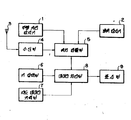
제4도는 종래예를 도시하는 블록도.4 is a block diagram showing a conventional example.
* 도면의 주요부분에 대한 부호의 설명* Explanation of symbols for main parts of the drawings
1 : 주행거리 감지기 2 : 방위 감지기1: mileage detector 2: bearing detector
3 : 안테나 4 : 수신부3: antenna 4: receiver
5 : 위치 검출부 6, 6A : 키 입력부5:
6B : 스케일 키 입력부 7A : 지도 데이타 기억부6B: Scale key input section 7A: Map data storage section
7B : 제1기억부 7C : 제2기억부7B: First Memory 7C: Second Memory
8,8A : 데이타 처리부 8B : 스케일 판정 처리부8,8A: data processing section 8B: scale determination processing section
8D : 기어부 선택부 9 : 표시부8D: gear section selection section 9: display section
본 발명은 이동체용 내비게이션 장치에 관한 것이며, 특히, 주행하고 있는 차량등의 이동체의 현재 위치와 목적지와의 간격거리에 따라서 그리고 이동체의 타각변화에 따라서 그 표시부에 표시되는 지도의 최적스케일을 설정할 수 있도록 된 이동체용 내비게이션 장치에 관한 것이다.BACKGROUND OF THE INVENTION 1. Field of the Invention The present invention relates to a navigation apparatus for a mobile vehicle, and in particular, an optimum scale of a map displayed on the display unit can be set according to the distance between the current position and the destination of a mobile vehicle, such as a vehicle driving, and the change of the steering angle of the mobile vehicle. The present invention relates to a navigation device for moving objects.
선박, 항공기, 자동차등의 각종의 이동체에 대해서 복수개의 인공위성으로부터 전파를 송신해서 그 현재 위치나 이동속도등을 확인하거나 결정하기 위해서 GPS측위 장치가 유용하다는 것이 주목되어 있다. 여기에서, GPS측위 장치는, 전 세계 측위 시스템(Grobal Positioning System)에 속하는 복수개의 인공위성으로 부터의 전파를 수신해서 이동체의 현재 위치를 알 수 있게 된 것이다.It has been noted that a GPS positioning device is useful for transmitting radio waves from a plurality of satellites to various moving objects such as ships, aircrafts, automobiles, etc. to check or determine the current position or moving speed. Here, the GPS positioning device can receive the radio waves from a plurality of satellites belonging to the global positioning system (Grobal Positioning System) to know the current position of the moving object.
종래부터 알려져 있듯이 이같은 GPS 측위장치를 써서 이뤄지는 측위조작은 통상, 3개 이상의 인공위성으로부터의 전파를 수신함으로서 행해지는 것이다. 그리고, 복수개의 인공위성으로 부터의 전파를 이동체측에서 동시에 수신되어서, 상기 복수개의 인공위성측에 설치되어 있는 시계장치와 이동체간에 설치되어 있는 시계장치와의 간격 정밀도의 차이에 기준하는 시간적인 차이에 대한 소요의 보정처리가 이뤄지고 나서 해당 이동체의 현재 위치를 적당한 표시수단으로 표시하도록 되어 있다. 이때, 필요한 지도정보가 현재 위치에 관한 정보와 중첩되어서 상기 표시수단으로 표시되어지게된다.As is known in the art, a positioning operation performed using such a GPS positioning device is usually performed by receiving radio waves from three or more satellites. Then, radio waves from a plurality of satellites are simultaneously received on the moving object side, and the time difference based on the difference in the interval accuracy between the clock device provided on the plurality of satellite sides and the clock device provided between the moving objects is determined. After the necessary correction processing is performed, the current position of the moving object is displayed by appropriate display means. At this time, necessary map information is displayed on the display means by overlapping the information on the current position.
또, 상기한 각종의 이동체를 위한 내비게이션 장치로서 소위 자립형인 것도 종래부터 알려져 있다. 이 자립형 내비게이션 장치는 전술된 GPS 내비게이션 장치와는 다르며, 인공위성으로 부터의 전파와 같은 외부로부터의 데이타에 의존함이 없이 스스로가 취득한 데이타만에 의해서 자체의 현재 위치를 알 수 있도록 된 것이다.Moreover, what is called a self-supporting type | system | group as a navigation apparatus for the said various kinds of moving bodies is known conventionally. This self-contained navigation device is different from the GPS navigation device described above, and it is possible to know its current position only by the data acquired by itself without relying on external data such as radio waves from satellites.
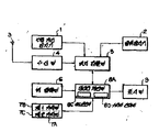
제4도는 종래의 이 종류의 장치를 도시하는 블록도이다. 이 제4도에 있어서, (3)은 위성전파수신용인 안테나이며, 이 안테나(3)의 출력측은 수신부(4)에 접속되어 있다. (1)은 주행거이 감지기, (2)는 방위감지기이며, 이것들은 수신부(4)의 출력측과 더불어 위치 검출부(5)에 접속되어 있다. 그리고, 이 위치 검출부(5)의 출력측은 데이타 처리부(8)에 접속되어 있으며 또, 키 입력부(6), 지도 데이타 기억부(7) 및 표시부(9)가 상기 데이타 처리부(8)에 접속되어 있다.4 is a block diagram showing a conventional apparatus of this kind. In FIG. 4,
다음으로, 그 동작에 대해서 설명한다. 차량등의 이동체의 조작자는 예컨대, 키 입력부(6)의 스타트키를 누르므로서 상기된 이동체용 내비게이션 장치를 기동시킨다. 이어서, 적당한 선택키와 같은 기능키를 누름으로서 GPS 내비게이션 기능 또는 자립형 내비게이션 기능중의 어느 하나를 선택한다. 지금, 전자의 기능이 선택된 것이라고 하면, 주행거리 감지기(1) 및 방위 감지기(2)는 도시되지 않는 기계적 스위치등으로 위치 검출부(5)로부터 떼어내지며 안테나(3)로 수신되는 위성 전파만에 의해서 이동체의 현재 위치나 이동방향이 확인되거나 결정되어 진다. 한편, 각종의 장해물의 존재로 GPS 내비게이션 기능을 선택할 수 없을 때인 자립형 내비게이션 기능을 선택해서 주행거리 감지기(1)이다. 방위 감지기(2)로부터 취득되는 데이타만에 기준해서 자체의 현재 위치나 이동방향의 확인이나 결정을 하게된다.Next, the operation will be described. An operator of a moving object such as a vehicle activates the above-described navigation device for the moving object by pressing the start key of the
그런데, 같은 종래부터의 장치에 있어서는 표시부(9)에 표시되는 것은 이동체의 현재 위치를 포함하고 있는 지도뿐이며, 또, 그 표시 스케일이 고정되어 있으므로서, 예컨대, 전지 이동체의 목적지가 현재 위치에서 멀리 떨어져 있어서 상기 표시부(9)의 1개의 표시 화면만으로는 양자를 일시에 볼 수 없는 경우가 있다. 이같은 때엔 이동체의 현재 위치를 포함하는 지도와 목적지를 포함하는 지도를 적당히 바꿔서 표시하는 조작이 필요하다.By the way, in the conventional device, only the map including the current position of the movable body is displayed on the
또한, 이동체의 이동속도에 불구하고, 그 표시 스케일이 고정되어 있으므로써, 예컨대, 이동체가 고속으로 이동하고 있을때에도 상세한 이동경로가 그대로 표시되어 있고, 이동체의 조작자가 표시화면을 정확하게 시인하는 것이 곤란한 일이 있다.In addition, despite the moving speed of the moving object, the display scale is fixed, so that, for example, the detailed moving path is displayed as it is even when the moving object moves at a high speed, and it is difficult for the operator of the moving object to visually recognize the display screen. There is a thing.
또한, 이동체의 이동에 따르는 타각변화에 불구하고, 그 표시 스케일이 고정되어 있으므로서, 예컨대 이동경로의 교차점에 있어서 이동체가 신속하게 커브될 것이 필요되어서 이동체의 치밀한 이동조작을 해야 때에도 자세한 이동경로가 그대로 표시되어 있으며, 이동체의 조작자가 표시화면을 정확하게 시인하는 것이 곤란한 일이 있다. 게다가, 이같은 시인조작을 이동체의 치밀한 이동조작과 더불어 행해야 되므로 이동체의 이동조작이 허실하게 된다는 위험성이 있다.In addition, despite the change in the steering angle caused by the movement of the moving object, the display scale is fixed, so that the moving object needs to be quickly curved, for example, at the intersection of the moving path, so that a detailed moving path is required even when the moving object is closely moved. It is displayed as it is, and it may be difficult for the operator of the moving object to visually recognize the display screen. In addition, there is a danger that the movement operation of the moving object is lost because such a poet operation must be performed together with the precise movement operation of the moving object.
종래의 장치는 상기된 것같은 구성을 가지며, 동작을 하는 것이므로 그 표시부에 표시되는 것은 이동체의 현재 위치를 포함하고 있는 지도뿐이며, 또 그 표시 스케일이 고정되어 있으므로 예컨대, 이동체의 목적지가 현재 위치에서 멀리 떨어져 있어서 상기 표시부의 1개의 표시 화면만으로는 양자를 일시에 볼 수 없는 일이 있어서 이동체의 현재 위치를 포함하는 지도와 목적지를 포함하는 지도를 적당히 바꿔서 표시하는 조작이 필요로 한다.The conventional apparatus has such a configuration as described above and operates, so that the only display on the display portion is a map containing the current position of the moving object, and since the display scale is fixed, for example, the destination of the moving object is moved from the current position. It may be so far that one display screen of the said display part may not be able to see both at once, and the operation which changes and displays the map containing the current position of a moving object, and the map containing a destination suitably is required.
또한, 이동체의 이동속도에 불구하고 그 표시 스케일이 고정되어 있으므로, 예컨대, 이동체가 고속으로 이동되고 있을 때에도 상세한 이동경로가 그대로 표시되어 있어서 이동체의 조작자가 표시 화면을 정확하게 시인하기 곤란한 일이 있다.In addition, since the display scale is fixed in spite of the moving speed of the moving object, the detailed moving path is displayed as it is even when the moving object is moving at high speed, for example, so that it is difficult for the operator of the moving object to visually recognize the display screen.
또한 이동체의 이동에 따르는 타각의 변화에 불구하고 그 표시 스케일이 고정되어 있으므로 예컨대, 이동경로의 교차점에 있어서 이동체가 신속하게 커브될 것이 필요로 되어서 이동체의 치밀한 이동조작을 해야할 때에도 자세한 이동경로가 그대로 표시되고 있으며, 이동체의 조작자가 표시 화면을 적확하게 시인하는 것이 곤란한 일이 있고, 또한, 이같은 시인 조작을 이동체의 치밀한 이동조작과 더불어 행해야 되므로 이동체의 이동 조작이 허실해진다는 위험성도 있다는 문제점이 있었다.In addition, the display scale is fixed in spite of the change of the steering angle due to the movement of the moving object, so that the moving object needs to be quickly curved at the intersection of the moving path, for example, so that the detailed moving path remains the same even when the moving object needs to be closely moved. There is a problem that it is difficult for the operator of the moving object to visually recognize the display screen accurately, and there is also a risk that such a moving operation must be performed together with the precise movement of the moving object, thereby losing the moving operation of the moving object. .
본 발명은 상기와 같은 문제점을 해결하기 위해 이뤄진 것이며, 이동체의 현재 위치와 목적지와 간격 거리에 따라서, 표시부에 표시되는 지도의 최적 스케일을 설정할 수 있도록 해서 이동체의 현재 위치를 포함하는 지도와 목적지를 포함하는 지도를 적당히 바꿔서 표시하는 조작이 불요하게 됨과 더불어, 지도의 표시법위에 따른 최적 스케일의 선택으로 그 표시화면이 매우 보기 쉽게 된 이동체용 내비게이션 장치를 얻는 것을 목적으로 하고, 또한 이동체의 이동속도에 따라서, 상기 표시부에 표시되는 지도의 최적 스케일을 설정할 수 있도록 해서, 이동체의 이동속도에 적합한 표시 지도를 용이하게 시인 할 수 있도록 된 이동체용 내비게이션 장치를 얻는 것을 목적으로 하며, 또한, 상기 이동체의 이동에 따르는 타각의 변화에 따라서 상기 표시부에 표시되는 지도의 최적 스케일을 설정할 수 있도록 해서 이동체의 타각변화에 적합된 표시지도를 용이하게 시인할 수 있도록 된 이동체용 내비게이션 장치를 얻는 것을 목적으로 한다.The present invention has been made to solve the above problems, and according to the current position, the destination and the distance of the moving object, it is possible to set the optimal scale of the map displayed on the display unit to determine the map and the destination including the current position of the moving object. It is aimed at obtaining a navigation device for a moving object whose display screen is very easy to see by selecting an optimal scale according to the display method of the map, and changing the display of the included map appropriately. Therefore, an object of the present invention is to obtain a navigation apparatus for a mobile body that enables the optimum scale of the map displayed on the display unit to be set so that the display map suitable for the moving speed of the mobile body can be easily recognized. According to the change of the steering angle according to the display unit To be set to the optimum scale of the map displayed to the purpose of obtaining a moving body navigation device to facilitate viewing the displayed map suitable for the steering angle change of the movable body.
본 발명에 관계하는 이동체용 내비게이션 장치는 이동체의 이동거리, 이동방위등에 관한 신호를 받아들여서 상기 이동체의 현재 위치를 검출하는 위치 검출부와 소정의 지도 데이타를 기억토록 된 지도 데이타 기억부와, 소요의 데이타나 지령을 입력하는 키 입력부와 상기 각종의 신호나 데이타 처리부와 상기 이동체의 현재 위치 및 해당 이동체의 목적지에 관련하는 지도를 표시토록 된 표시부로 되어 있으며, 상기 키 입력부에는 스케일 키 입력부가 설치되며, 또, 상기 데이타 처리부에는 세일판정 처리부가 설치되며 또한 상기 위치 검출부엔 이동체의 타각변화를 검지하는 타각 감지기가 접속되며, 상기 지도 데이타 기억부는 복수개의 기억부로 분할되며 또, 상기 데이타 처리부엔 속도 연산부 및 기억부 선택부가 설치되어 있다.A navigation apparatus for a moving object according to the present invention includes a position detecting unit for receiving a signal relating to a moving distance, a moving direction, etc. of the moving object to detect a current position of the moving object, a map data storage unit storing predetermined map data, A key input unit for inputting data or commands, and a display unit for displaying various signals or data processing units, a map relating to the current position of the moving object and the destination of the moving object, and the key input unit is provided with a scale key input unit. In addition, the data processing unit is provided with a sail determination processing unit, and the position detection unit is connected to a steering angle detector for detecting a change in the steering angle of the moving object, and the map data storage unit is divided into a plurality of storage units, and the data processing unit is a speed calculating unit. And a storage section selector.
본 발명에 있어선 이동체의 현재 위치와 목적지와 사이의 거리 및 이동체의 이동속도와 이동체의 이동에 따르는 타각변화에 따라서 표시부에 표시되는 지도의 최적 스케일이 설정된다.In the present invention, the optimum scale of the map displayed on the display unit is set according to the distance between the current position and the destination of the moving object, the moving speed of the moving object, and the steering angle change according to the movement of the moving object.
이하, 본 발명의 제1실시예를 도면에 대해서 설명한다.Hereinafter, a first embodiment of the present invention will be described with reference to the drawings.
제1a도는 본 발명의 제1실시예를 설명하는 블럭도이다. 제1a도에 잇어서 3은 위성 전파 수신용 안테나이며, 이 안테나(3)의 출력측은 수신부(4)에 접속되어 있다. 1은 주행거리 감지기, 2는 방위 감지기이며, 이것들은 수신부(4)의 출력측과 더불어 위치 검출부(50)에 접속되어 있다. 그리고, 이 위치검출부(5)의 출력측은 스케일 판정 처리부(8B)를 포함한 데이타 처리부(8A)에 접속되어 있고 또, 스케일, 키 입력부(6B)를 포함한 키 입력부(6A), 지도 데이타 기억부(7) 및 표시부(9)가 상기 데이타 처리부 (8A)에 접속되어 있다.1A is a block diagram illustrating a first embodiment of the present invention. In FIG. 1A, 3 is an antenna for satellite radio wave reception, and the output side of this
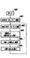
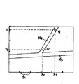
제2a도는 상기 실시예를 설명하기 위한 순서도이다. 또, 제3a 및 3b도는 상기 실시예에 있어서의 표시부의 표시화면 예시도이다. 여기에서 제3a도는 이동체의 현재 위치 (P)와 목적지(Q)와 사이의 거리가 상당히 있는 경우의 예시도이며, 이에 대해서 제3b도는 이동체가 진행해서 목적지(Q)에 근접해졌을 경우의 예시도이다. 또한, 제3도에 있어서, (R1내지 R6)는 이동체의 이동경로이다. 또, (X0, Y0)는 이동체의 현재 위치(P)의 좌표치, (X1,Y1)은 해당 이동체의 목적지(Q)의 좌표치이며, 양자간의 거리는,2A is a flowchart for explaining the above embodiment. 3A and 3B are exemplary views of the display screen of the display unit in the above embodiment. Here, FIG. 3a is an exemplary view when the distance between the current position P and the destination Q of the moving object is considerably large. On the other hand, FIG. 3b is an exemplary view when the moving object moves closer to the destination Q. to be. In Fig. 3, (R 1 to R 6 ) is a moving path of the moving body. In addition, (X 0 , Y 0 ) is the coordinate value of the current position (P) of the moving object, (X 1 , Y 1 ) is the coordinate value of the destination (Q) of the moving object, the distance between the two,
X=X1-X0……………………………………………………………………(1)X = X 1 -X 0 ... … … … … … … … … … … … … … … … … … … … … … … … … … (One)
Y=Y1-Y0……………………………………………………………………(2)Y = Y 1 -Y 0 ... … … … … … … … … … … … … … … … … … … … … … … … … … (2)
로 나타내어져 있다. 그리고, (S1)은 표시지도의 스케일의 가늠으로서의 눈금이다.It is represented by And (S 1 ) is a scale as a scale of the scale of the display map.
다음에, 제1a도에 도시한 상기 실시예의 동작에 대해서, 제2a도 및 제3a,3b도를 적절히 참조하면서 설명한다. 차량등의 이동체의 조작자는 예컨대, 키 입력부(6A)상의 스타트키를 누름으로서 상기 실시예 장치를 기동시킨다(S20). 이어서, 목적지 (Q)에 관한 좌표치(X1,Y1)를 키 입력부(6A)로 설정한다. 그리고, 위성전파로서의 GPS 신호나 이동체 자체가 들어넣을 수 있는 자립형 신호가 안테나(3), 주행거리 감지기(1), 방위 감지기(2)를 거쳐서 들어넣어져서 데이타 처리부(8A)로, 이동체의 현재위치(P)에 관한 좌표치(X0,Y0)가 산출된다(S22). 다음의 스텝(S23)에 있어선 상기된 (1),(2)식으로 이동체의 현재 위치(P)와 목적지(Q)의 사이의 거리 데이타가 산출된다.Next, the operation of the embodiment shown in FIG. 1A will be described with reference to FIGS. 2A and 3A and 3B as appropriate. An operator of a moving object such as a vehicle activates the above-described device by, for example, pressing a start key on the
예를들어, 전술된 바와 같이, 현재 위치의 좌표치(경도 및 위도)를 (Xc, Yc)라하고 목적지의 좌표치를 (Xd,Yd)라하면, 현재 위치와 목적지간의 경도차, 위도차로 거리 계산을 한다. 즉, 경도, 위도에 대해서 각각의 단위 길이(예컨대, 1도 단위 길이)를 Lx, Ly라하면(단, 경도 방향의 단위 길이는 위도에 따라서 변한다; 위도가 높으면 당단위 길이는 작아진다), 때문에 현재 위치와 목적지의 평균 위도로부터 Lx를 결정한다.For example, as described above, if the coordinate value (longitude and latitude) of the current position is (Xc, Yc) and the coordinate value of the destination is (Xd, Yd), the distance is calculated by the longitude and latitude difference between the current position and the destination. Do it. In other words, when the unit length (eg, 1 degree unit length) is Lx and Ly for longitude and latitude, the unit length in the longitude direction changes according to the latitude; the higher the latitude, the smaller the unit length. Therefore, Lx is determined from the average latitude of the current location and the destination.
이에 따라, 현재 위치와 목적기간의 거리는 다음과 같이 결정된다.Accordingly, the distance between the current position and the target period is determined as follows.
(((Xd-Xc)x Lx)2+((Yd-Yc)xLy2)1/2 (((Xd-Xc) x Lx) 2 + ((Yd-Yc) xLy 2 ) 1/2
이 산출된 거리 데이타에 기준해서 스케일 판정 처리부(8B)의 작용으로 대응 지도에 대한 적절한 스케일의 판정 선택이 이뤄진다. 이 판정/선택의 결과는 예컨대, 표시부(9)의 적소에 표시하는 것으로 지정된다. 그리고, 이 지시에 기준하는 대응 스케일의 설정이 스케일, 키 입력부(6B)로 되며 (S24), 이에 귀속해서 대응하는 지도의 표시가 상기 설정 스케일 하에서 이뤄진다(S25).Based on the calculated distance data, the scale determination processing section 8B acts to determine the appropriate scale decision for the corresponding map. The result of this determination / selection is, for example, designated to be displayed in place on the
지금 이동체의 현재 위치(P)가 이동경로(R4)상에 있다고 하면, 목적지(Q)와 사이의 거리는 상당히 크며, 이때엔 제3a도에 도시하는 것같은 비교적 작은 스케일로 지도표시가 이뤄지게 된다.If the current position P of the moving object is now on the movement route R 4 , the distance between the destination Q is quite large, and the map is displayed on a relatively small scale as shown in FIG. .
이후는 어떤 소정의 시간 인터벌을 가지고 스텝(S22)로 되돌아가서 이동체의 현재 위치(P)의 산출/수정이 이뤄져간다. 그리고, 이동체의 이동이 수행되어서 이동체의 현재 위치(P)가 이동경로(R4)상까지 변위했다고치면, 이때엔 목적지(q)와 사이의 거리는 작아지며, 제3b도에 도시하듯이 이에 따른 스케일에 있어서의 지도 표시가 이뤄지게 된다.Thereafter, the flow returns to step S22 at a predetermined time interval to calculate / modify the current position P of the moving object. If the current position P of the movable body is displaced up to the moving path R 4 by the movement of the movable body, then the distance between the destination q is reduced, and as shown in FIG. The map display on the scale is made.
다음에는 본 발명의 제2실시에를 도면에 대해서 설명한다.Next, a second embodiment of the present invention will be described with reference to the drawings.
제1b도는 본 발명의 제2실시예를 설명하는 블럭도이다. 이 제1b도에 있어서, (3)은 위성 전파 수신용 안테나이며, 이 안테나(3)의 출력측은 수신부(4)에 접속되어 있다. (1)은 주행거리 감지기, (2)는 방위 감지기이며, 이것들은 수신부(4)의 출력측과 더불어 위치 검출부(5)에 접속되어 있다. 그리고, 이 위치 검출부(5)의 출력측은 스케일 속도 연산부(8C) 및 기억부 선택부(8D)를 포함한 데이타 처리부(8A)에 접속되어 있고 또, 스케일, 키 입력부(6B), 제1,제2기억부(7B,7C)로 분할된 지도 데이타 기억부 (7A) 및 표시부(9)가 상기 데이타 처리부(8A)에 접속되어 있다.1B is a block diagram for explaining a second embodiment of the present invention. In FIG. 1B,
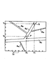
제2b도는 상기 실시예를 설명하기 위한 순서도이다. 또, 제3c도는 상기 실시예에 있어서의 표시부의 표시화면 예시도이다. 여기에서 제3a도를 이동체의 이동속도가 소정치를 너어서고 있는 경우의 예시도이며, 이에 대해서 제3d도는 상기 이동체의 이동속도가 소정치 이하일 경우의 예시도이다. 상기 제3c도, 제3b도에 있어서, (R1내지 R5)는 이동체의 이동경로 이다. 이 이동경로(R1내지 R5)중에서 (R1내지 R2)는 자동차 전용도로, 국도, 주요지방도로와 같은 지선도로이다. 또, (X0, Y0)는 이동체의 현재 위치(P)의 좌표치, (X1,Y1)는 해당 이동체의 목적지(Q)의 좌표치이다. 그리고, (S1)은 표시지도의 스케일의 가늠으로서의 눈금이다.2B is a flowchart for explaining the above embodiment. 3C is an exemplary view of the display screen of the display unit in the above embodiment. Here, FIG. 3A is an illustration of the case where the moving speed of the moving object is over a predetermined value, while FIG. 3D is an illustration of the case where the moving speed of the moving object is below a predetermined value. In FIG. 3C and FIG. 3B, (R 1 to R 5 ) are moving paths of the moving body. Among these moving paths R 1 to R 5 , R 1 to R 2 are branch roads such as automobile-only roads, national roads, and major regional roads. (X 0 , Y 0 ) is the coordinate value of the current position P of the moving object, and (X 1 , Y 1 ) is the coordinate value of the destination Q of the moving object. (S1) is a scale as a scale of the scale of the display map.
다음에, 제1b도에 도시한 상기 실시예의 동작에 대해서 제2b도 및 제3c, 제3d도를 적절히 참조하면서 설명한다. 차량등의 이동체의 조작자는 예컨대, 키 입력부(6A)상의 스트키를 누름으로서 상기 실시예 장치를 기동시킨다(S20). 이어서, 목적지(Q)에 관한 좌표치(X1,Y1)를 키 입력부(6A)로 설정한다. 그리고, 위성전파로서의 GPS신호나 이동체 자체가 들어넣을 수 있는 자립형 신호가 안테나(3), 주행거리 감지기(1), 방위 감지기(2)를 거쳐서 들어넣어져서 데이타 처리부(8A)로, 이동체의 현재위치(P)에 관한 좌표치(X0,Y0)가 산출된다(S22). 어떤 소정의 시간 인터벌을 가지고 이동체의 이동속도가 연산된다. 또한, 이 연산은 데이타 처리부(8A)내의 속도 연산부(8C)에 의해서 이뤄지는 것이며, 예컨대 이동체의 단위시간당의 이동거리를 구함으로서 얻어진다. 또한, 상기 주행거리 감지기로 부터 출력되는 펄스수에 의해서 주행거리도 계산된다. 예를들어, 차륜(타이어)이 1회전할때마다 출력되는 펄스수가 n(회)이고, 차륜의 원주 길이를 Lh(m)이며, 일정시간 주행했을때의 펄스수가 N(회)라고 하면 이때의 주행 거리는 다음과 같다.Next, the operation of the embodiment shown in FIG. 1B will be described with reference to FIGS. 2B, 3C, and 3D. An operator of a moving object such as a vehicle activates the above-described device by, for example, pressing a key on the
LhxN/n(m)LhxN / n (m)
그리고 여기에서 산출된 이동속도에 대응하는 스케일 설정이 이뤄진다(S25). 상기 제1b도의 지도 데이타 기억부(7A)는 전술한 바와 같이, 제1,제2기억부(7B,7C)로 분할되어 있다. 그리고, 제1기억부(7B)에는 간선도로(R1,R2)와 같은 스케일이 클때에 대응하는 지도 데이타가 포함되며, 또 제2기억부(7C)에는 지선도로(R3, 내지 R5)와 같은 스케일이 작을때에 대응하는 지도 데이타가 포함되어 있다.And the scale setting corresponding to the movement speed calculated here is made (S25). As described above, the map data storage unit 7A shown in FIG. 1B is divided into first and second storage units 7B and 7C. The first storage unit 7B includes map data corresponding to a large scale such as the trunk roads R 1 and R 2 , and the second storage unit 7C includes branch roads R 3 to R. The map data corresponding to the small scale such as 5 ) is included.
여기에서, 이동체의 이동속도가 예컨대, 시고 50km를 넘어서고 있을때엔 제3c도에 예시되고 있듯이 스케일이 크게 설정되며, 데이타 처리부(8A)내의 기억부 선택부(8D)로 지도 데이타 기억부(7A)내의 제1기억부(7B)가 억세스되어서, (R1,R2)와 같은 간선도로만이 표시된다. 이것에 대해서, 이동체의 이동속도가 시속 50km 이하일때엔 제3d도에 예시되어 있듯이 스케일이 작게 설정되며, 상기 지도 데이타 기억부 (7A)내의 제1,제2기억부(7B,7C)의 쌍방이 선택되어 (R3내지 R5)와 같은 지선도로도 표시된다.Here, when the moving speed of the moving object exceeds 50 km, for example, as shown in FIG. 3C, the scale is set large, and the map data storage unit 7A is stored in the storage unit selection unit 8D in the data processing unit 8A. The first storage portion 7B in the interior is accessed, so that only the trunk road such as (R 1 , R 2 ) is displayed. On the other hand, when the moving speed of the moving object is 50 km or less per hour, as shown in FIG. 3d, the scale is set small, and both of the first and second memory units 7B and 7C in the map data storage unit 7A are provided. Is selected and displayed as branch roads such as (R 3 to R 5 ).
이같이 해서 대응 스케일에 적합한 지도가 표시되어서, 이 지도를 시인하면서 이동체의 이동조작이 행해지는데, 어떤 소정의 시간 인터벌을 가지고 스텝(S22)으로 되돌아가고, 그때마다 현재 위치를 확인하면서 상기 이동체의 이동속도를 연산하고, 그 연산결과에 대응하는 스케일의 설정과 대응지도의 표시가 적절하게 행해지는 것이다.In this way, a map suitable for the corresponding scale is displayed, and the movement of the moving object is performed while viewing the map. The moving of the moving object is returned to step S22 with a predetermined time interval, and the current position is checked each time. The speed is calculated, and the setting of the scale corresponding to the calculation result and the display of the corresponding map are appropriately performed.
또다른 본 발명의 제3실시에에 대하여 설명한다.Another third embodiment of the present invention will be described.
본 발명의 제3실시예를 도면에 대해서 설명한다.A third embodiment of the present invention will be described with reference to the drawings.
제1c도는 본 발명의 제3실시예를 설명하는 블럭도이다. 이 제1c도에 있어서 (3)은 위성 전파 수신용 안테나이며, 이 안테나(3)의 출력측은 수신부(4)에 접속되어 있다. (1)은 주행거리 감지기, (2)는 방위 감지기이며, 이것들은 수신부(4)의 출력측과 더불어 위치 검출부(5)에 접속되어 있다. 또한 이 위치 검출부(5)에는 이동체의 이동에 따르는 타각의 변화를 알기 위한 타각 감지기(10)가 접속되어 있다. 그리고, 이 위치 검출부(5)의 출력측은 기억부 선택부(8D)를 포함한 데이타 처리부(8A)에 접속되어 있으며, 또, 키 입력부(6), 제1,제2기억부(7B,7C)로 분할된 지도 데이타 기억부(7A) 및 표시부(9)가 상기 데이타 처리부(8A)에 접속되어 있다.1C is a block diagram for explaining a third embodiment of the present invention. In FIG. 1C,
제2c도는 상기 실시예를 설명하기 위한 순서도이다. 또, 제3e도,3f도는 상기 실시예에 있어서의 표시부의 표시화면 예시도이다. 여기에서 제3e도는 이동체의 이동에 따르는 타각의 크기가 소정치를 넘어서고 있는 경우의 예시도이며 이것에 대해서 제3f도는 상기 이동체의 이동에 따르는 타각의 크기가 소정치 이하일 경우의 예시도이다. 또한, 이 제3도에 있어서, (R1내지 R5)는 이동체의 이동경로이다. 이 이동경로(R1내지 R2)중에서(R1및 R2)는 자동차용 도로, 국도, 주요지방도로와 같은 간선도로이며, (R3내지 R5)는 시군읍도와 같은 지선도로이다. 또, (X0,X0)는 이동체의 현재 위치(P)의 좌표치, (X1,Y1)은 해당 이동체의 목적지(Q)의 좌표치이다. 그리고 (S1)은 표시 지도의 스케일의 기능으로서의 눈금이다.2C is a flowchart for explaining the above embodiment. 3E and 3F are exemplary views of the display screen of the display unit in the above embodiment. Here, FIG. 3E is an illustration of the case where the size of the steering angle due to the movement of the movable body exceeds a predetermined value, while FIG. 3F is an example of the case where the size of the steering angle following the movement of the moving object is smaller than or equal to the predetermined value. In FIG. 3, (R 1 to R 5 ) are moving paths of the moving body. Among these moving paths R 1 to R 2 , R 1 and R 2 are trunk roads such as automobile roads, national roads, and major local roads, and R 3 to R 5 are branch roads such as municipalities. In addition, (X 0 , X 0 ) is the coordinate value of the current position P of the moving object, and (X 1 , Y 1 ) is the coordinate value of the destination Q of the moving object. And S1 is a scale as a function of the scale of the display map.
다음에, 제1c도에 도시한 상기 실시예의 동작에 대해서 제2c도 및 제3e도, 제3f도를 적절히 참조하면서 설명한다. 차량등의 이동체의 조작자는 예컨대, 키 입력부 (6A)상의 스타트키를 누름으로서 상기 실시예 장치를 가동시킨다(S20). 이어서, 목적지(Q)에 관한 좌표치(X1,Y2)를 키 입력부(6A)로 설정한다. 그리고, 위성전파로서의 GPS신호나 이동체 자체가 들어넣을 수 있는 자립형 신호가 안테나(3), 주행거리 감지기(1), 방위 감지기(2)를 거쳐서 들어넣어져서 데이타 처리부(8A)로, 이동체의 현재위치(P)에 관한 좌표치(X0,Y0)가 산출된다(S22). 다음의 스텝(S22)에 있어선 타각감지기(10)로부터의 신호를 받아 들여서, 이동체의 이동에 따른 타각의 변화가 검지된다.Next, the operation of the embodiment shown in FIG. 1C will be described with reference to FIGS. 2C, 3E, and 3F. An operator of a moving object such as a vehicle activates the above-described device by pressing a start key on the
타각의 변화를 검지하기 위해서는, 핸들의 회전각에 따라서 전압이 변화하게한 조타각 감지기를 쓴다.In order to detect a change in the steering angle, a steering angle detector in which the voltage changes according to the rotation angle of the handle is used.
예를들어, 차량이 직선 주행할때의 타이어의 상태(핸들의 상태)의 전압을 Vm(V)이라하고, 핸들을 좌측으로 1°돌릴때마다 dv(V) 전압이 내려가고, 핸들을 우측으로 1' 돌릴때마다 dv(V) 전압이 올라간다고하자 (핸들의 회전각은 우회전을 ˝정˝이라고 한다).For example, the voltage of the state of the tire (handle) when the vehicle is traveling in a straight line is called Vm (V). Whenever the steering wheel is turned 1 ° to the left, the dv (V) voltage decreases and the steering wheel is turned to the right. Each time you turn 1 ', the dv (V) voltage goes up (the rotation angle of the handle is called the right turn).
그리고, 핸들의 회전각에 대한 조타각의 비를 1/N으로 햇을 때, 출력 전압을 Vo(V)로 하면 조타각![]()
![]()
θ((Vo-Vm)/dv)x(1/N))[°]θ ((Vo-Vm) / dv) x (1 / N)) [°]
(단 위회전을 ˝정˝, 좌회전을 ˝부˝라 한다)(We call unit rotation and turn left)
이어서, 여기에서 검지된 타각변화의 크기에 대응하는 스케일의 설정이 이뤄지며(S24), 이에 계속해서 대용지도의 표시가 이뤄진다(S25).Subsequently, a scale corresponding to the magnitude of the rudder angle change detected here is set (S 24 ), and the display of the surrogate map is subsequently performed (S25).
예를들어, 지도의 스케일과 지도 데이타는 1:1로 대응한다. 따라서, 지도를 표시하는 스케일이 결정되면, 그 스케일에 대응하는 지도 데이타를 지도 데이타 기억장치로부터 읽어내어, 지도를 그리고 표시하게 된다.For example, the map scale and map data correspond to 1: 1. Therefore, when the scale for displaying the map is determined, map data corresponding to the scale is read from the map data storage device to draw and display the map.
상기 제1c도의 지도 데이타 기억부(74)는 전술한 바와 같이 제1,제2기억부 (7B,7C)로 분할되어 있다. 그리고, 제1기억부(7B)에는 간선도로(R2,R3)와 같은 스케일이 클때에 대응하는 지도 데이타가 포함되며, 또 제2기억부(7C)에는 지선도로(R1-R2)와 같은 스케일이 작을때 대응하는 지도데이타가 포함되어 있다.The map data storage unit 74 of FIG. 1C is divided into first and second memory units 7B and 7C as described above. The first memory 7B includes map data corresponding to a large scale such as the trunk roads R 2 and R 3 , and the second memory 7C includes branch roads R 1 -R 2. When the scale is small, the corresponding map data is included.
여기에서 이동체의 이동에 따르는 타각의 변화가 예컨대, 진행방향에 대해서 ±45°를 초과하고 있을때면, 제3e도에 예시되어 있듯이 스케일이 크게 설정되며, 데이타 처리부(8A)내의 기억부 선택부(8D)로 지도 데이타 기억부(7A)내의 제2기억부 (7B)가 억세스되어서(R1,R2)와 같은 간선도로만이 표시된다. 이것에 대해서, 이동체의 이동에 따르는 타각의 변화가 진행방향에 대해서 ±45° 이하일때면 제3f도에 예시되어 있듯이 스케일이 작게 설정되며, 상기 지도 데이타 기억부(7A)내의 제1,제2기억부 (7B,7C)의 쌍방이 선택되어서 (R3, 내지 R5)와 같은 지선도로도 표시되어 있다.Here, when the change in the steering angle caused by the movement of the moving object exceeds, for example, ± 45 ° with respect to the moving direction, the scale is set large as illustrated in FIG. 3E, and the storage section selection section in the data processing section 8A ( 8D), the second storage unit 7B in the map data storage unit 7A is accessed, and only the main roads such as R 1 and R 2 are displayed. On the other hand, when the change of the steering angle caused by the movement of the moving object is ± 45 ° or less with respect to the moving direction, the scale is set small as illustrated in FIG. 3F, and the first and second memories in the map data storage 7A are made. Both of the portions 7B and 7C are selected and are also indicated by branch lines such as (R 3 to R 5 ).
이같이 해서, 대응 스케일에 적합한 지도가 표시 되어서 이 지도를 시인하면서 이동체의 이동조작이 이뤄지는데, 어떤 소정의 시간 인터벌을 가지고 스텝(S22)로 되돌아가, 그때마다의 현재위치를 확인하면서 상기 이동체의 이동에 따르는 타각의 크기를 검지하고, 그 검지결과에 대응하는 스케일의 설정과 대응지도의 표시가 적절하게 행해진다.In this way, a map suitable for the corresponding scale is displayed, and the moving object is moved while acknowledging the map, and returns to step S22 with a predetermined time interval, and confirms the current position of the moving object at that time. The size of the rudder angle accompanying the movement is detected, and the setting of the scale corresponding to the detection result and the display of the corresponding map are appropriately performed.
이상 설명된 바와 같이, 본 발명에 관계하는 이동체용 내비게이션 장치는 이동체의 이동거리, 이동방위등에 관한 신호를 받아들여서 상기 이동체의 현재 위치를 검출하는 위치 검출부와, 소정의 지도 데이타를 기억토록된 지도 데이타 기억부와, 소요의 데이타나 지령을 입력하는 키 입력부와 상기 각종의 신호나 데이타 등을 처리해서 소요의 출력 데이타를 산출하는 데이타 처리부와, 상기 이동체의 현재위치 및 해당 이동체의 목적지에 관련하고 지도를 표시토록된 표시부를 포함해서 구성되어 있으며, 상기 키 입력부엔 스케일, 키입력부가 설치되며, 또 상기 데이타 처리부엔 스케일 판정 처리부가 설정되고 있어서 상기 이동체의 현재위치와 목적지간의 거리에 따라서, 상기 표시부에 표시되는 지도의 최적 스케일을 설정할 수 있으므로 이동체의 현재위치를 포함하는 지도와 목적지를 포함하는 지도를 바꿔서 표시하는 조작이 불요하게 됨과 더불어, 지도의 표시화면이 매우 보기쉽게 된다는 효과가 나타내어지는 것이다.As described above, the navigation apparatus for a moving object according to the present invention receives a signal relating to a moving distance, a moving direction, etc. of the moving object, and detects a current position of the moving object, and a map configured to store predetermined map data. A data storage unit, a key input unit for inputting required data or instructions, a data processing unit for processing the various signals or data and calculating required output data, and a current position of the moving object and a destination of the moving object. The display unit is configured to display a map, wherein the key input unit is provided with a scale and a key input unit, and the data processing unit has a scale determination processing unit set therein according to the distance between the current position of the moving object and the destination. Since the optimal scale of the map displayed on the display can be set, In addition soon as an operation for changing the displayed map comprising a map and a destination, including the re-positioned unnecessary, to which the display screen is very easy to see that the effect of the map indicated.
또한, 상기 지도 데이타 기억부는 복수개의 기억부로 분할되며, 상기 데이타 처리부엔 속도 연산부 및 기억 선택부가 설치되어 있어서 이동체의 이동속도에 따라서, 상기 표시부에 표시되는 지도의 최적 스케일을 설정할 수 있으므로 이동체의 이동조작중의 표시화면의 시인이 매우 용이해진다는 효과가 나타내어진다.In addition, the map data storage unit is divided into a plurality of storage units, and the data processing unit is provided with a speed calculating unit and a memory selecting unit so that the optimum scale of the map displayed on the display unit can be set according to the moving speed of the moving object. The effect that viewing of the display screen during operation becomes very easy is exhibited.
또한, 상기 위치 검출부엔 이동체의 타각 변화를 검지하는 타각 감지기가 접속되며, 상기 지도 데이타 기억부는 복수개의 기억부로 분할되며, 또, 상기 데이타 처리부엔 속도 연산부 및 기억부 선택부가 설치되어 있어서 상기 이동체의 이동에 따르는 타각 변화에 따라서, 상기 표시부에 표시되는 지도의 최적 스케일을 설정할 수 있도록 되어 있으므로, 지도의 표시범위에 따른 최적 스케일의 선택으로, 예컨대, 이동경로의 교차점에 있어서 이동체가 신속 커브할 것이 필요로 되어 이동체의 치밀한 이동 조작을 해야할 때에도, 표시부에 표시되는 지도의 최적 스케일을 설정할 수 있도록 되어 있으므로, 지도의 표시범위에 따른 최적 스케일의 선택으로 예컨대, 이동경로의 교차점에 있어서 이동체가 신속 커브할 것이 필요로 되어 이동체의 치밀한 이동 조작을 해야할 때에도 이것에 적합한 이동경로가 표시된 화면이 주여져서 이동체의 조작자에 의한 표시화면의 정확한 시인이 용이해지며 또한, 이같은 시인조작에 따르는 이동체의 치밀한 이동조작도 용이해진다는 효과가 나타내어진다.In addition, the position detection unit is connected to a steering angle detector for detecting a change in the steering angle of the moving object, the map data storage unit is divided into a plurality of storage unit, and the data processing unit is provided with a speed calculating unit and a storage unit selection unit, Since the optimum scale of the map displayed on the display unit can be set according to the change in the steering angle caused by the movement, it is necessary to select the optimal scale according to the display range of the map, for example, to quickly curve the moving object at the intersection of the movement route. Since the optimum scale of the map displayed on the display unit can be set even when the movement of the moving object needs to be performed precisely, the moving object is quickly curved at the intersection of the moving path, for example, by selecting the optimal scale according to the display range of the map. Dense movement of moving object Even when an operation is required, a screen displaying a moving path suitable for this operation is given, so that an accurate visual recognition of the display screen by an operator of the moving object is facilitated, and the precise movement operation of the moving object according to such a viewing operation is also facilitated.
Claims (4)
Applications Claiming Priority (6)
| Application Number | Priority Date | Filing Date | Title |
|---|---|---|---|
| JP62315319A JPH01156618A (en) | 1987-12-15 | 1987-12-15 | Navigation device for moving body |
| JP87-315319 | 1987-12-15 | ||
| JP62318670A JP2656051B2 (en) | 1987-12-18 | 1987-12-18 | Navigation device for mobile objects |
| JP87-318670 | 1987-12-18 | ||
| JP87-322680 | 1987-12-22 | ||
| JP62322680A JPH01165918A (en) | 1987-12-22 | 1987-12-22 | Navigation apparatus for moving body |
Publications (2)
| Publication Number | Publication Date |
|---|---|
| KR890010578A KR890010578A (en) | 1989-08-09 |
| KR930000137B1 true KR930000137B1 (en) | 1993-01-09 |
Family
ID=27339465
Family Applications (1)
| Application Number | Title | Priority Date | Filing Date |
|---|---|---|---|
| KR1019880016693A KR930000137B1 (en) | 1987-12-15 | 1988-12-15 | Navigation device for moving object |
Country Status (3)
| Country | Link |
|---|---|
| US (1) | US5084822A (en) |
| KR (1) | KR930000137B1 (en) |
| DE (1) | DE3842179C3 (en) |
Families Citing this family (60)
| Publication number | Priority date | Publication date | Assignee | Title |
|---|---|---|---|---|
| EP0489915B2 (en) * | 1989-08-24 | 2000-02-09 | TSUYUKI, Toshio | Navigation apparatus and method |
| US5274387A (en) * | 1990-06-06 | 1993-12-28 | Mazda Motor Corporation | Navigation apparatus for vehicles |
| JP2995687B2 (en) * | 1990-06-06 | 1999-12-27 | マツダ株式会社 | Vehicle navigation system |
| JP2664800B2 (en) * | 1990-09-19 | 1997-10-22 | 三菱電機株式会社 | Vehicle navigation system |
| DE4032198C2 (en) * | 1990-10-11 | 1995-10-19 | Daimler Benz Aerospace Ag | Transport monitoring method and arrangement for carrying out the method |
| JPH04270373A (en) * | 1991-01-17 | 1992-09-25 | Mitsubishi Electric Corp | On-vehicle navigation device |
| JP3155022B2 (en) * | 1991-04-23 | 2001-04-09 | パイオニア株式会社 | Car navigation system |
| DE4121095B4 (en) * | 1991-06-26 | 2004-09-16 | Robert Bosch Gmbh | Process for displaying maps on a computer-controlled screen |
| JPH0520365A (en) * | 1991-07-12 | 1993-01-29 | Fujitsu Ltd | Managing system for plural drawings in geographical information managing system |
| JP2644935B2 (en) * | 1991-07-25 | 1997-08-25 | 株式会社日立製作所 | Terrain information processing method and device |
| US5285391A (en) * | 1991-08-05 | 1994-02-08 | Motorola, Inc. | Multiple layer road memory storage device and route planning system |
| US5515284A (en) * | 1991-09-25 | 1996-05-07 | Zexel Corporation | Storage medium for map information for navigation system and system for offering map information for navigation system |
| JPH05119701A (en) * | 1991-10-29 | 1993-05-18 | Clarion Co Ltd | Map display device for car navigation |
| DE69231206T2 (en) * | 1991-11-01 | 2001-03-01 | Motorola Inc | VEHICLE ROUTE GUIDANCE SYSTEM |
| US10361802B1 (en) | 1999-02-01 | 2019-07-23 | Blanding Hovenweep, Llc | Adaptive pattern recognition based control system and method |
| US8352400B2 (en) | 1991-12-23 | 2013-01-08 | Hoffberg Steven M | Adaptive pattern recognition based controller apparatus and method and human-factored interface therefore |
| US7290627B1 (en) * | 1992-04-13 | 2007-11-06 | Conrad Oliver Gardner | Extended range motor vehicle having ambient pollutant processing |
| GB9210470D0 (en) * | 1992-05-15 | 1992-07-01 | Securicor Datatrak Ltd | Vehicle guidance apparatus |
| JPH06137882A (en) * | 1992-10-28 | 1994-05-20 | Toyota Motor Corp | Route guiding device for vehicle |
| US5406491A (en) * | 1993-03-26 | 1995-04-11 | Trimble Navigation Limited | Navigational system for trip routing |
| JP3409377B2 (en) * | 1993-08-09 | 2003-05-26 | 松下電器産業株式会社 | Navigation device |
| JP3385657B2 (en) * | 1993-08-10 | 2003-03-10 | トヨタ自動車株式会社 | Car navigation system |
| US5629693A (en) * | 1993-11-24 | 1997-05-13 | Trimble Navigation Limited | Clandestine location reporting by a missing vehicle |
| DE69510493T2 (en) * | 1994-04-15 | 1999-10-28 | Nissan Motor | Vehicle navigation system |
| TW317618B (en) * | 1994-12-01 | 1997-10-11 | Toyota Motor Co Ltd | |
| US5682525A (en) | 1995-01-11 | 1997-10-28 | Civix Corporation | System and methods for remotely accessing a selected group of items of interest from a database |
| JPH08271278A (en) * | 1995-03-28 | 1996-10-18 | Matsushita Electric Works Ltd | Navigation apparatus |
| DE19516647A1 (en) * | 1995-05-05 | 1996-11-07 | Bayerische Motoren Werke Ag | Navigation system for motor vehicle |
| US5699255A (en) * | 1995-10-18 | 1997-12-16 | Trimble Navigation Limited | Map transmission for in-vehicle navigation system with dynamic scale/detail adjustment |
| US5938709A (en) * | 1996-11-22 | 1999-08-17 | Case Corporation | Panning display of GPS field maps |
| US5870689A (en) * | 1996-11-22 | 1999-02-09 | Case Corporation | Scouting system for an agricultural field |
| US5961573A (en) * | 1996-11-22 | 1999-10-05 | Case Corporation | Height control of an agricultural tool in a site-specific farming system |
| US6029106A (en) * | 1996-11-22 | 2000-02-22 | Case Corporation | Global position correction for the electronic display of field maps |
| US5978723A (en) * | 1996-11-22 | 1999-11-02 | Case Corporation | Automatic identification of field boundaries in a site-specific farming system |
| US5902343A (en) * | 1996-11-22 | 1999-05-11 | Case Corporation | Automatic scaling of GPS field maps |
| US5878371A (en) * | 1996-11-22 | 1999-03-02 | Case Corporation | Method and apparatus for synthesizing site-specific farming data |
| JPH1138872A (en) * | 1997-07-17 | 1999-02-12 | Toyota Motor Corp | Map data delivery system and map data acquisition apparatus suitable for this system |
| JPH1165436A (en) * | 1997-08-21 | 1999-03-05 | Toyota Motor Corp | Data selection support device, and map data processing system and processor including same support device |
| US7268700B1 (en) | 1998-01-27 | 2007-09-11 | Hoffberg Steven M | Mobile communication device |
| DE19815035B4 (en) * | 1998-03-05 | 2006-06-22 | Volkswagen Ag | Method and device for displaying information for a navigation device |
| US7904187B2 (en) | 1999-02-01 | 2011-03-08 | Hoffberg Steven M | Internet appliance system and method |
| DE19909385A1 (en) * | 1999-03-04 | 2000-09-07 | Mannesmann Vdo Ag | Vehicle navigation procedures |
| JP2001264099A (en) * | 2000-03-15 | 2001-09-26 | Honda Motor Co Ltd | Navigation system for vehicle |
| US7118498B2 (en) * | 2000-06-16 | 2006-10-10 | Skyhawke Technologies, Llc | Personal golfing assistant and method and system for graphically displaying golf related information and for collection, processing and distribution of golf related data |
| US8172702B2 (en) | 2000-06-16 | 2012-05-08 | Skyhawke Technologies, Llc. | Personal golfing assistant and method and system for graphically displaying golf related information and for collection, processing and distribution of golf related data |
| US7121962B2 (en) * | 2000-12-19 | 2006-10-17 | Reeves G George | Golf round data system with cellular telephone and player help features |
| JP4453796B2 (en) * | 2001-05-29 | 2010-04-21 | 日本電気株式会社 | Map display method and system for position information display terminal |
| JP4058318B2 (en) * | 2002-09-24 | 2008-03-05 | 富士重工業株式会社 | Information display device and information display method |
| US9818136B1 (en) | 2003-02-05 | 2017-11-14 | Steven M. Hoffberg | System and method for determining contingent relevance |
| DE10313223B4 (en) * | 2003-03-25 | 2020-10-29 | Robert Bosch Gmbh | Navigation device for route guidance of a motor vehicle |
| CN1768248A (en) * | 2003-04-02 | 2006-05-03 | 黄丽云 | Digital map display |
| DE102004009463A1 (en) * | 2004-02-27 | 2005-09-15 | Robert Bosch Gmbh | Method for storing map data representing traffic route sections in a navigation system and navigation system |
| JP2006132132A (en) * | 2004-11-04 | 2006-05-25 | Hitachi Constr Mach Co Ltd | Work management device and working machine equipped therewith |
| US20070078596A1 (en) | 2005-09-30 | 2007-04-05 | John Grace | Landmark enhanced directions |
| KR100760116B1 (en) * | 2006-02-03 | 2007-09-18 | 엘지전자 주식회사 | Method for changing map scale in navigation system |
| JP2008216205A (en) * | 2007-03-07 | 2008-09-18 | Fujitsu Ltd | On-vehicle navigation device |
| US7995079B2 (en) * | 2007-04-16 | 2011-08-09 | Research In Motion Limited | Automatic map zoom-level adaptation |
| EP1983302A1 (en) * | 2007-04-16 | 2008-10-22 | Research In Motion Limited | Automatic map zoom-level adaptation |
| DE102010021042A1 (en) | 2010-05-19 | 2011-11-24 | Fraunhofer-Gesellschaft zur Förderung der angewandten Forschung e.V. | Method for computer-assisted controlling of vehicle, particularly driverless transport vehicle, involves fitting laser scanner in vehicle, where measured value tuple is detected by laser scanner in scanner layer |
| GB2492381A (en) * | 2011-06-30 | 2013-01-02 | Tomtom Int Bv | Controlling a map displayed on a navigation apparatus in order to maximise the display of a remaining route |
Family Cites Families (16)
| Publication number | Priority date | Publication date | Assignee | Title |
|---|---|---|---|---|
| JPS5939800B2 (en) * | 1980-10-27 | 1984-09-26 | 本田技研工業株式会社 | Fixed distance display method in driving route display device |
| JPS57137862A (en) * | 1981-02-19 | 1982-08-25 | Alps Electric Co Ltd | Direction detecting device |
| JPS57169785A (en) * | 1981-04-13 | 1982-10-19 | Nissan Motor | Travelling guidance system for car |
| US4675676A (en) * | 1983-03-09 | 1987-06-23 | Nippondenso Co. Ltd. | Map display system |
| JPS6024412A (en) * | 1983-07-20 | 1985-02-07 | Hitachi Ltd | Navigation device |
| US4608658A (en) * | 1984-04-13 | 1986-08-26 | Pencept, Inc. | Method and apparatus for removing noise at the ends of a stroke caused by retracing |
| JPS60230185A (en) * | 1984-04-27 | 1985-11-15 | 三菱電機株式会社 | On-board navigation apparatus |
| JPS6175375A (en) * | 1984-04-28 | 1986-04-17 | 三菱電機株式会社 | On-board navigator |
| JPS60239791A (en) * | 1984-05-15 | 1985-11-28 | 三菱電機株式会社 | On-board navigator |
| US4689747A (en) * | 1984-06-21 | 1987-08-25 | Nippondenso Co., Ltd. | Vehicle navigational apparatus for displaying a road map |
| US4633709A (en) * | 1984-08-07 | 1987-01-06 | Nippondenso Co., Ltd. | Vehicle turn angle detecting device |
| DE3588138T2 (en) * | 1984-10-22 | 1997-04-17 | Etak Inc | DEVICE FOR PRESENTING A CARD |
| DE3519276A1 (en) * | 1985-05-30 | 1986-12-04 | Robert Bosch Gmbh, 7000 Stuttgart | NAVIGATION SYSTEM FOR VEHICLES |
| JP2695414B2 (en) * | 1987-07-10 | 1997-12-24 | アイシン・エィ・ダブリュ株式会社 | Vehicle navigation system |
| JPH0820265B2 (en) * | 1987-07-10 | 1996-03-04 | アイシン・エィ・ダブリュ株式会社 | Vehicle navigation system |
| US4943925A (en) * | 1987-10-30 | 1990-07-24 | Aisin Aw Co., Ltd. | Navigation apparatus based on present position calculating system |
-
1988
- 1988-12-14 US US07/284,369 patent/US5084822A/en not_active Expired - Fee Related
- 1988-12-15 KR KR1019880016693A patent/KR930000137B1/en not_active IP Right Cessation
- 1988-12-15 DE DE3842179A patent/DE3842179C3/en not_active Expired - Fee Related
Also Published As
| Publication number | Publication date |
|---|---|
| KR890010578A (en) | 1989-08-09 |
| US5084822A (en) | 1992-01-28 |
| DE3842179C2 (en) | 1992-08-27 |
| DE3842179C3 (en) | 1998-03-26 |
| DE3842179A1 (en) | 1989-06-29 |
Similar Documents
| Publication | Publication Date | Title |
|---|---|---|
| KR930000137B1 (en) | Navigation device for moving object | |
| KR910004416B1 (en) | Navigator | |
| KR900008856B1 (en) | Navigation apparatus for vehicle | |
| JPH0518771A (en) | Gps navigation device | |
| JP3155394B2 (en) | Car navigation system | |
| KR100208804B1 (en) | Navigation system for use in mobile objects and processing method thereof | |
| JP2783139B2 (en) | Travel position display device | |
| JP2783924B2 (en) | Vehicle position detection device | |
| CA2470284C (en) | Vehicle navigation system | |
| JPH03138516A (en) | Navigation device for traveling body | |
| JP2656051B2 (en) | Navigation device for mobile objects | |
| JP4877774B2 (en) | Navigation device | |
| JPH06289778A (en) | Vehicular position detector | |
| EP0601712A1 (en) | Navigation system | |
| JP2619065B2 (en) | Navigator device for vehicles | |
| JP3550901B2 (en) | Navigation device | |
| JPS6326589A (en) | Generation device for map data with estimation information for gps | |
| JPH0476609B2 (en) | ||
| JP2530154B2 (en) | Vehicle navigation system | |
| JPH06109828A (en) | Mover-mounted navigator apparatus | |
| JP2907937B2 (en) | Moving object position detection device | |
| JP2685624B2 (en) | Navigation system for moving objects | |
| JPH0235312A (en) | Navigation apparatus for moving body | |
| JP3176106B2 (en) | Travel guidance device for vehicles | |
| KR0180874B1 (en) | Navigation system for a vehicle |
Legal Events
| Date | Code | Title | Description |
|---|---|---|---|
| A201 | Request for examination | ||
| E902 | Notification of reason for refusal | ||
| G160 | Decision to publish patent application | ||
| E701 | Decision to grant or registration of patent right | ||
| GRNT | Written decision to grant | ||
| FPAY | Annual fee payment |
Payment date: 19981228 Year of fee payment: 7 |
|
| LAPS | Lapse due to unpaid annual fee |