KR920009321B1 - Dispensing apparatus for vending machine - Google Patents
Dispensing apparatus for vending machine Download PDFInfo
- Publication number
- KR920009321B1 KR920009321B1 KR1019860004762A KR860004762A KR920009321B1 KR 920009321 B1 KR920009321 B1 KR 920009321B1 KR 1019860004762 A KR1019860004762 A KR 1019860004762A KR 860004762 A KR860004762 A KR 860004762A KR 920009321 B1 KR920009321 B1 KR 920009321B1
- Authority
- KR
- South Korea
- Prior art keywords
- motor
- product
- flapper
- rotary shaft
- signal
- Prior art date
Links
Images


Classifications
-
- G—PHYSICS
- G07—CHECKING-DEVICES
- G07F—COIN-FREED OR LIKE APPARATUS
- G07F11/00—Coin-freed apparatus for dispensing, or the like, discrete articles
-
- G—PHYSICS
- G07—CHECKING-DEVICES
- G07F—COIN-FREED OR LIKE APPARATUS
- G07F11/00—Coin-freed apparatus for dispensing, or the like, discrete articles
- G07F11/02—Coin-freed apparatus for dispensing, or the like, discrete articles from non-movable magazines
- G07F11/04—Coin-freed apparatus for dispensing, or the like, discrete articles from non-movable magazines in which magazines the articles are stored one vertically above the other
- G07F11/10—Coin-freed apparatus for dispensing, or the like, discrete articles from non-movable magazines in which magazines the articles are stored one vertically above the other two or more magazines having a common delivery chute
-
- G—PHYSICS
- G07—CHECKING-DEVICES
- G07F—COIN-FREED OR LIKE APPARATUS
- G07F11/00—Coin-freed apparatus for dispensing, or the like, discrete articles
- G07F11/02—Coin-freed apparatus for dispensing, or the like, discrete articles from non-movable magazines
- G07F11/04—Coin-freed apparatus for dispensing, or the like, discrete articles from non-movable magazines in which magazines the articles are stored one vertically above the other
- G07F11/16—Delivery means
- G07F11/24—Rotary or oscillatory members
Abstract
내용 없음.No content.
Description
제1a도는 본 발명의 상품 반출장치에 사용되는 모우터 제어회로의 1실시예를 도시하는 도면.FIG. 1A is a diagram showing one embodiment of a motor control circuit used in the product discharging device of the present invention. FIG.
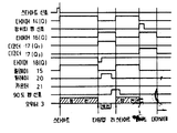
제1b도는 제1a도에 도시한 제어회로의 각부의 출력 상태를 도시한 타이밍 차아트.FIG. 1B is a timing chart showing the output state of each part of the control circuit shown in FIG. 1A.
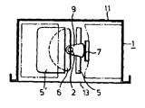
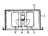
제2a도 및 제2b도는 각각 본 발명의 상품 반출 장치의 주요부를 도시하는 정면도 및 A-A'선의 단면도.2A and 2B are front views and sectional views taken on line A-A ', respectively, showing main parts of the product discharging device of the present invention.
제3a도, 제4a도 및 제5a도는 각각 제2a도에 도시하는 상품 반출 장치의 작동 추이를 도시하는 부분 정면도.3A, 4A, and 5A are partial front views showing the operating trend of the product discharging device shown in FIG. 2A, respectively.
제3b도, 제4b도 및 제5b도는 각각 제3a도, 제4a도 및 제5a도의 A-A'선의 단면도.3B, 4B, and 5B are sectional views taken along the line AA ′ of FIGS. 3A, 4A, and 5A, respectively.
* 도면의 주요부분에 대한 부호의 설명* Explanation of symbols for the main parts of the drawings
1 : 상품 수납부 2 : 회전축1: product storage unit 2: rotation axis
3 : 모우터 4, 4' : 플래퍼(flapper)축3:
5, 5' : 플래퍼 6 : 회동 제어판5, 5 ': flapper 6: rotation control panel
7, 7' : 세퍼레이터 8, 8', 8'' : 상품7, 7 ':
9 : 세퍼레이터 캠 11 : 콜럼본체9: Separator Cam 11: Colum Body
12 : 콜럼중판 13 : 앞판12: Colum mid edition 13: Front edition
14 : 타이머 15 : 릴레이14
16 : 타이머 17 : 디코더16: timer 17: decoder
18 : 타이머 19 : 앤드 게이트18: Timer 19: And Gate
20 : 릴레이 21 : 카우터20: relay 21: counter
본 발명은 자동판매기의 상품 반출 장치, 특히 소형 종이팩에 든 음료를 반출하는 상품 반출 장치에 관한 것이다.The present invention relates to a product dispensing apparatus of a vending machine, in particular a product dispensing apparatus for discharging a beverage in a small carton.
종래의 그러한 상품 반출 장치로서 일본 특개소 59-105199호 공보에 기재된 상품반출장치(이하 바로쌓기 플래퍼 방식 반출 장치로 칭한다)가 알려져 있다.As such a conventional product carrying out apparatus, the goods carrying out apparatus described in Unexamined-Japanese-Patent No. 59-105199 (henceforth a stacking flapper system carrying apparatus) is known.
후술하는 바와같이 이 바로쌓기 플래퍼 방식 반출 장치에 있어서는 반출될 상품의 변형등에 의하여 상품이 원활하게 낙하하지 않고 상품의 낙하에 시간이 걸린다. 따라서 닫히는 플래퍼와 반출장치의 함체 사이에 상품이 끼어서 그로인해 모우터가 록(lock)상태가 되는 경우가 있다.As described later, in this stacking flapper discharging device, the product does not drop smoothly due to deformation of the product to be carried out, and it takes time for the product to fall. Therefore, there may be a case where a product is caught between the closing flapper and the housing of the discharging device, thereby causing the motor to be locked.
종래의 반출장치에서는 상기와 같이 모우터가 록상태가 되었을 때 모우터의 보호상 록상태가 된 후 소정시간 통전후 모우터에의 통전을 중단하도록 한 보호회로가 설치되어 필요에 따라 「판매중지」또는 「품절」등의 외부 표시를 하고 있다. 따라서 그후 반출장치내에 상품이 남아있어도 판매를 할수 없게된다.In the conventional carrying out device, as described above, when the motor is in the locked state, a protection circuit is installed to stop the power supply to the motor after energizing for a predetermined time after the motor is in the protective lock state. Or "out of stock". Therefore, even after the goods remain in the carrying out device can not be sold.
본 발명의 목적은 상기와 같은 결함이 없는 상품 반출 장치를 제공하는 것이다.It is an object of the present invention to provide a product dispensing apparatus having no such defects.
본 발명은 상하방향으로 긴 상품수납부와, 이 상품수납부의 하부에 연결된 상품취출구와, 상기 상품수납부의 중앙에 설치되고, 상하방향으로 연장한 회전축과, 이 회전축을 사이에 두어 대향되도록 구성하고 또한 이 상품수납부의 하단을 개폐하도록 상하방향으로 회동이 가능하도록 설치된 1쌍의 플래퍼와, 이 플래퍼의 회동을 상기 회전축의 회전에 따라 규정하는 회동제어판을 가지며, 상기 플래퍼의 각각에 쌓인 상품을 상기 플래퍼의 개(開)동작으로 상기 상품 취출구에 낙하 반출하도록 한 자동판매기의 상품 반출 장치에 있어서, 상기 1쌍의 플래퍼의 양쪽이 닫힌 상태에 있을 때의 상기 회전축의 회전각도 위치를 검출하고 대기 위치 신호를 송출하는 동시에 상기 1쌍의 플래퍼의 어느 한쪽이 개방상태가 되었을 때의 상기 회전축의 회전각도 위치를 검출하고, 개방상태 신호를 송출하는 검출수단과, 상기 플래퍼에 의하여 상기 상품의 반출이 실시되도록 상기 회전축을 소정의 방향으로 회전시키는 방향으로 상기 모우터를 구동하고, 미리 정해진 시간에 상기 대기위치 신호를 수신하지 못하면 상기 모우터를 오프로 하고, 상기 개방상태 신호가 수신될 때까지 상기 회전축을 역전시키도록 상기 모우터를 역전구동하고, 상기 개방상태 신호를 받으면 이 모우터를 재차 오프로 하여 상기 회전축을 상기의 소정의 방향으로 회전시키도록 상기 모우터를 구동하도록 한 모우터 제어회로를 구비한 것을 특징으로 하는 자동판매기의 상품 반출 장치이다.The present invention is configured so as to face the product storage portion that is long in the vertical direction, a product outlet connected to the lower portion of the product storage portion, a rotary shaft installed in the center of the product storage portion and extending in the vertical direction, and facing the rotation shaft. And a pair of flappers installed so as to be rotatable in the up and down direction to open and close the lower end of the goods storage portion, and a rotation control panel for defining the rotation of the flapper in accordance with the rotation of the rotary shaft. A product dispensing apparatus of a vending machine for dropping and discharging to the product dispensing opening by means of an opening operation, wherein the rotation angle position of the rotary shaft when both of the pair of flappers are in a closed state is detected and a standby position signal At the same time when one of the pair of flappers is opened, Detection means for transmitting a signal of an opening state, and driving the motor in a direction in which the rotary shaft is rotated in a predetermined direction so that the product is carried out by the flapper, and the standby position at a predetermined time. If no signal is received, the motor is turned off, and the motor is reversed to reverse the rotating shaft until the open state signal is received, and when the open state signal is received, the motor is turned off again. And a motor control circuit configured to drive the motor so as to rotate the rotating shaft in the predetermined direction.
이하 본 발명은 실시예로 설명한다.Hereinafter, the present invention will be described by way of examples.
우선 제2a도 및 제2b도를 참조하면, 상품 반출장치의 구성에 대하여 설명한다. (11)은 단면 형상이 대체로 「![]()
![]()
상품 수납부(1)의 중앙부에는 상하방향으로 연장한 회전축(2)이 삽입되고 도시를 생략한 상품수납부(1)의 상단 및 하단에서 지도리형식을 지지된다. 이 회전축(2)은 상품수납부(1)의 최상부에 설치되는 모우터(3)에 연결되고, 소정의 방향으로 회전한다. 콜럼본체(11)의 전면 하부에는 앞판(13)이 고착되고, 콜럼본체(11)의 배면판 및 이것에 대응하는 앞판(13)에는 상품수납부(1)내에서 앞뒤방향으로 연장한 플래퍼측(4) 및 (4')이 회전축(2)에 접근해서 설치된다. 이 플래퍼축(4) 및 (4')에는 각각이 축을 중심으로 하여 회동이 가능하도록 플래퍼(5) 및 (5')가 설치된다. 회전축(2)의 하부에는 수평상태에 있는 플래퍼(5)(5')의 하면과 당접하는 위치에 대체로 부채꼴을한 회동제어판(6)이 설치된다. 회동제어판(6)은 회전축(2)의 회동에 따라 플래퍼(5) 및 (5')를 구동한다.The
플래퍼(5) 및 (5')의 상방에는 세퍼레이터(7) 및 (7')가 회전이 가능하도록 축으로 지지된다. 세퍼레이터(7) 및 (7')는 판매대기 상태에 있는 플래퍼(5) 및 (5')위의 상품 (8) 및 (8')의 바로위에 있는 상품과 대응하는 위치에 설치된다. 세퍼레이터(7) 및 (7')의 축지지부보다 약간 하방에는 대체적으로 반원판 형상의 세퍼레이터 캠(9)이 회전축(2)에 서로 끼워지고, 나사로 고정된다. 그리고 세퍼레이터 캠(9)은 회전축(2)의 회전에 따라서 세퍼레이터(7) 및 (7')를 교대로 회동한다.Above the
다음에 상기의 반출장치의 반출작용에 대하여 설명한다.Next, the carrying out action of the carrying out device will be described.
판매 대기 상태로 소정 경화(硬貨)의 투입에 따르는 판매신호에 의하여 모우터(3)에 통전되어 회전축(2)의 회전으로 회동제어판(6)과 세퍼레이터 캠(9)이 제5b도 중 파선화살표 방향으로 회전구동된다. 회동제어판(6)이 플래퍼(5)에서 이탈되는 조금 전의 회전 각도로 세퍼레이터(7)가 세퍼레이터 캠(9)에 의해서 상방으로 회동구동되어서 콜럼본체(11)의 우측판과의 사이에 상품(8)의 바로 위의 상품(8'')을 협지하기 시작한다. 제3a도 및 제3b도의 도시와 같이 회전축(2)이 처음 위치에서 90도 회전하면 플래머(5)는 걸어 고정상태가 해제되어 플래퍼축(4)을 중심으로 하여 하방을 회동하여 플래퍼(5)위에 얹힌 상품(8)이 낙하반출된다.The motor 3 is energized by the sales signal following the input of a predetermined coin in the stand-by state, and the
그러나 그 바로 위의 상품(8'')은 세퍼레이터(7)와 콜럼본체(11)의 우측판으로 끼어져 있으므로 낙하하지 않는다. 계속해서 회동제어판(6), 세퍼레이터 캠(9)은 회동하여 제4a도 및 제4b도의 도시와 같이 처음의 위치에서 180°회전한 시점에서 정지한다(판매 대기 상태). 이때 플래퍼(5)도 회동제어판(6)의 회동에 따라 밀어올려져서 원래의 수평위치로 복귀되어 세퍼레이터(7)는 세퍼레이터캠(9)의 회동에 따라 하방으로 회동한다. 그리고 복귀한 플래퍼(5) 위에는 다음의 상품(8'')과 그 위의 상품이 협지상태가 해제되어 미끄러져 내린다. 다음의 판매신호가 도래하면 동일한 동작으로 상품(8')이 낙하 반출된다.However, the
그런데, 종이팩에 든 음료등의 경우 제3a도 및 제3b도의 도시와 같이 상품(8)의 바로 위의 상품(8'')은 세퍼레이터(7)에 압압되어 변형한다. 이 경우 상품(8'')의 하단부가 도면과 같이 바깥쪽으로 부풀어서 그 결과 상품(8'')의 낙하반출시의 저항이 증대한다. 이 저항의 증대로 상품(8'')의 낙하가 지연되어 플래퍼(5)가 열려있을 동안에 낙하가 안되어 제5a도 및 제5b도의 도시와 같이 플래퍼(5)와 콜럼본체의 우측판과의 사이에 상품(8'')이 끼이는 일이 있다. 여기에서 제1a도를 참조하여 이 상품반출장치에 사용되는 모우터 제어회로에 대하여 설명한다.By the way, in the case of a drink etc. contained in a carton, the
상기와 같이 판매 대기 상태에서 소정의 경화 투입에 따르는 판매신호(스타아트 신호)는 오어게이트(14a)를 개재하여 타이머(14)에 입력된다. 타이머(14)는 이 스타아트 신호가 고레벨에서 저레벨으로 변화할 때, 즉 하강에서 구동되고, 미리 정해진 시간(예를들면 6초간) 고레벨의 신호를 송출한다. 이 고레벨신호는 인버어터(15a)를 개재하여 릴레이(15)에 입력되고, 릴레이(15)가 동작해서(릴레이(15)는 저레벨 입력으로 동작한다) 그 접점(15b)을 전원(+24V)과 연결하고, 모우터(3)에는 실선화살표의 방향으로 전류가 흘러 모우터(3)가 회전을 시작한다(이때의 회전 방향을 우방향으로 한다).As described above, the sales signal (star art signal) according to the predetermined coin input is input to the
한편, 모우터(3)의 회전으로 회전축(2)은 소정의 위치(대기위치)에서 소정의 방향으로 회동한다. 회전축(2)이 대기위치에서 있는 경우에는 검출스위치(도시생략)에 의하여 정위치 캠신호(대기 위치신호)가 송출되고, 이 정위치 캠신호는 타이머(16)의 A단자에 인가된다. 이 정위치 캠신호는 회전축(2)의 회동을 개시하면 고레벨에서 저레벨이 된다.On the other hand, the
통상의 경우 스타아트신호가 입력되어, 즉 모우터가 기동하고 나서 소정의 시간(예를들면 6초) 이내에 회전축(2)은 180도 회전하여 재차 대기위치로 돌아가므로, 정위치 캠 신호는 저레벨에서 고레벨이 된다. 정위치 캠 신호가 고레벨이 된 시점에서(이때 타이머(14)의 Q단자로 부터의 출력은 저레벨이 된다) 타이머(16)의 Q단자로부터는 고레벨이 출력된다. 따라서 디코더(17)의 A 및 B단자에는 고레벨이 입력되고, 이 결과 Q3단자로부터 고레벨 신호가 출력되고(이하 이 신호를 제1의 리세트 신호로 호칭한다). 상품 반출 장치가 리세트되어서 상품의 판매가 종료한다(디코더(17)의 Q1단자의 출력은 저레벨이다).Normally, the star cam signal is input, i.e., within a predetermined time (e.g. 6 seconds) after the motor is started, the
다음에 제1b도를 참조하여, 상기와 같이 플래퍼(5)와 콜럼본체(11)의 사이에 상품이 끼이면 모우터(3)가 록상태가 되어 소정시간(6초) 경과해도 회전축(2)은 대기 위치에서 복귀하지 않는다. 따라서 타이머(14)의 Q단자로 부터의 출력은 저레벨이 되어 릴레이(15)는 접점(15b)을 접지하므로 모우터로의 통전이 정지된다. 한편 타이머(14)의 Q단자로부터의 출력이 고레벨에서 저레벨으로 변화되므로(정위치 캠 신호는 저레벨이다), 타이머(16)의 Q단자로 부터 고레벨이 출력된다. 한편 정위치 캠 신호는 저레벨이므로 즉, 디코더(17)의 A단자에는 저레벨, B단자에는 고레벨이 입력되므로 디코더(17)의 Q3단자는 저레벨(즉 제1의 리세트신호는 출력이 안된다), Q1단자는 고레벨이 된다(이하 Q1단자로 부터의 신호를 타임업 신호로 호칭한다). 이 타임업 신호는 소정시간만 출력된다. 그리고 이 타임업 신호는 타이머(18) 및 타이머(14)에 입력된다.Next, referring to FIG. 1B, if the product is caught between the
타이머(18)의 A단자에 타임업 신호가 입력되면 타이머(18)는 소정의 시간(예를들면 1초간) 후에![]()
![]()
모우터(3)의 역전으로 플래퍼(5)가 개방상태가 되며, 즉 회전축(2)이 대기 위치로부터 90도 회동된 위치가 되면 검출스위치에 의하여 앤드게이트(19)에는 저레벨이 입력되므로 앤드게이트(19)의 출력은 저레벨이 되어 릴레이(20)의 접점(20b)은 접지되어 모우터(3)에 대한 통전이 단절된다.When the
그후(소정시간 경과후), 디코더(17)로 부터의 타임업 신호의 송출이 정지된다. 타임업신호의 정지에 의하여, 즉 디코더(17)의 Q1단자로부터의 출력이 고레벨에서 저레벨이 되면 타이머(14)의 Q단자로부터의 출력은 소정시간 고레벨이 된다. 또 타이머(18)의![]()
![]()
타이머(14)로 부터의 고레벨 신호에 의하여 상기와 동일하게 모우터(3)에는 실선화살표로 표시하는 바와같이 전류가 흘러서 모우터(3)는 정전하고, 회전축(2)은 소정의 방향으로 회동한다. 소정시간(6초간) 경과후 타이머(14)의 Q단자의 출력은 저레벨이 된다. 이 시점에서 회전축(2)이 대기 위치에 복귀하고 있으면 상기와 같이 정위치 캠 신호가 타이머(16) 및 디코더(17)에 입력되어 디코더(17)로부터 제1의 리세트 신호가 출력되어 상품 반출 장치가 리세트된다.By the high level signal from the
또, 상기와 같이 모우터(3)를 정지, 역전, 정지 및 정전의 순으로 일련의 동작을 해도 모우터(3)의 록상태가 계속되는 경우에 모우터 제어회로는 상기의 일련의 동작을 소정의 회수만 실시한다. 그리고 카운터(21)는 타임업 신호가 소정회수(예를들면 4회)입력되면 카운트업하여 고레벨(이하 제2의 리세트 신호로 호칭한다)을 출력하여 상품 반출 장치를 리세트하는 동시에 결함의 발생을 표시기(도시를 생략)에 표시한다.In addition, in the case where the locked state of the motor 3 continues even if the motor 3 is operated in the order of stopping, reversing, stopping and power failure as described above, the motor control circuit determines the above-described series of operations. Only recovery is carried out. The counter 21 counts up when the time-up signal is input a predetermined number of times (for example, four times), outputs a high level (hereinafter referred to as a second reset signal), resets the product discharging device, and generates a defect. Is displayed on an indicator (not shown).
상기의 상품 반출 장치에서는 모우터(3)가 록상태가 되면, 즉 플래퍼(5)와 콜럼본체(11)와의 사이에 상품이 끼이면 일단 모우터에의 통전을 중단하고 모우터를 역전시켜서 플래퍼(5)를 개방상태(회전축(2)이 대기상태에서 90도 회동한 위치)로 하여, 모우터(3)를 정지한다. 그 결과 상품은 낙하반출된다. 그후 모우터(3)를 정전시켜서 회전축(2)을 대기상태로 복귀하고 있다. 모우터(3)의 정지, 역전, 정지, 정전의 일련의 동작을 소정회수 실시하고 있으므로 1회의 일련 동작으로 상품이 낙하반출이 안되고 정상의 반출동작으로 복귀가 안되고 있는 경우라도 그 만큼 낙하반출의 확률을 높일 수가 있다.In the merchandise dispensing apparatus described above, when the motor 3 is locked, that is, when the product is caught between the
이상의 설명과 같이 본 발명에 의하면 상품이 플래퍼와 상품 수납부 상자체와의 사이에 끼었을 때 모우터를 일단 정지시킨 후 소정의 회전축의 회전각도까지 역전시켜서 상품을 낙하반출시키고, 그후 모우터를 재차 정지시켜서 정전하도록 했으므로 종래와 같이 상품이 낙하반출이 안되는 결함이 발생하는 일은 거의 없다.As described above, according to the present invention, when the product is sandwiched between the flapper and the product storage box, the motor is stopped once, and then the product is dropped and discharged by reversing the rotation angle of the predetermined rotating shaft, and then the motor is moved. Since it was made to stop again and a blackout was performed, the defect which a product does not drop-out rarely occurs like conventionally.
Claims (1)
Applications Claiming Priority (2)
| Application Number | Priority Date | Filing Date | Title |
|---|---|---|---|
| JP1985090026U JPS6327255Y2 (en) | 1985-06-17 | 1985-06-17 | |
| JP60-90026(U) | 1985-06-17 |
Publications (2)
| Publication Number | Publication Date |
|---|---|
| KR870000663A KR870000663A (en) | 1987-02-19 |
| KR920009321B1 true KR920009321B1 (en) | 1992-10-15 |
Family
ID=13987167
Family Applications (1)
| Application Number | Title | Priority Date | Filing Date |
|---|---|---|---|
| KR1019860004762A KR920009321B1 (en) | 1985-06-17 | 1986-06-16 | Dispensing apparatus for vending machine |
Country Status (4)
| Country | Link |
|---|---|
| US (1) | US4854477A (en) |
| JP (1) | JPS6327255Y2 (en) |
| KR (1) | KR920009321B1 (en) |
| GB (1) | GB2178416B (en) |
Families Citing this family (29)
| Publication number | Priority date | Publication date | Assignee | Title |
|---|---|---|---|---|
| JPS63175285U (en) * | 1987-04-30 | 1988-11-14 | ||
| ES2025912A6 (en) * | 1990-07-30 | 1992-04-01 | Azkoyen Ind Sa | Improvements to automatic vending machines |
| US5297922A (en) * | 1991-05-22 | 1994-03-29 | Piexx Company | Test sample changer |
| US5368190A (en) * | 1992-03-30 | 1994-11-29 | Hieb; Larry E. | Apparatus for vending work objects |
| ES2066697B1 (en) * | 1992-12-29 | 1995-08-16 | Azkoyen Ind Sa | IMPROVEMENTS INTRODUCED IN AUTOMATIC PRODUCT VENDING COLUMNS. |
| US6384402B1 (en) | 1998-04-29 | 2002-05-07 | Automated Merchandising Systems | Optical vend-sensing system for control of vending machine |
| JP2000103404A (en) * | 1998-09-29 | 2000-04-11 | Sanyo Electric Co Ltd | Medicine feed device |
| US7635059B1 (en) * | 2000-02-02 | 2009-12-22 | Imonex Services, Inc. | Apparatus and method for rejecting jammed coins |
| US6732014B2 (en) * | 2001-02-27 | 2004-05-04 | Crane Co. | System for accomplishing product detection |
| US7286901B2 (en) * | 2001-02-27 | 2007-10-23 | Crane Co. | Method and system for accomplishing product detection |
| US8548625B2 (en) * | 2001-08-23 | 2013-10-01 | Crane Merchandising Systems, Inc. | Optical vend sensing system for product delivery detection |
| US6772906B2 (en) * | 2001-12-13 | 2004-08-10 | Inland Finance Company | Apparatus and method for vending from a vending machine |
| US7032776B2 (en) * | 2002-08-08 | 2006-04-25 | The Vendo Company | Vending machine bucket drive control |
| US7565222B2 (en) * | 2004-01-15 | 2009-07-21 | Fawn Engineering Corporation | Economical optical system to provide reasonable assurance of completed vend or vendible items from vending machines |
| US20060118573A1 (en) * | 2004-11-03 | 2006-06-08 | Ganz Brian L | Automated small item dispense module |
| CN103679945A (en) * | 2012-09-06 | 2014-03-26 | 鸿富锦精密工业(武汉)有限公司 | Vending machine |
| CN103886685A (en) * | 2012-12-20 | 2014-06-25 | 鸿富锦精密工业(武汉)有限公司 | Cargo dropping device |
| TW201426652A (en) * | 2012-12-20 | 2014-07-01 | Hon Hai Prec Ind Co Ltd | Goods dropping device |
| CN103886686A (en) * | 2012-12-20 | 2014-06-25 | 鸿富锦精密工业(武汉)有限公司 | Goods-pile passage |
| CN104077849A (en) * | 2013-03-29 | 2014-10-01 | 鸿富锦精密工业(武汉)有限公司 | Vending machine |
| MY184766A (en) * | 2014-01-10 | 2021-04-21 | Fuji Electric Co Ltd | Product discharging device |
| JP6441816B2 (en) * | 2014-01-10 | 2018-12-19 | 富士電機株式会社 | Product dispensing device |
| JP6273939B2 (en) * | 2014-03-19 | 2018-02-07 | 富士電機株式会社 | Product dispensing device |
| WO2016084598A1 (en) * | 2014-11-28 | 2016-06-02 | 富士電機株式会社 | Product dispensing device |
| CN107209972B (en) | 2015-02-27 | 2019-07-30 | 富士电机株式会社 | Goods discharging device |
| CN104828452B (en) * | 2015-05-11 | 2017-03-22 | 江苏迅捷装具科技有限公司 | Vertical article storage distribution device and medicine distributor |
| JP6686397B2 (en) * | 2015-12-03 | 2020-04-22 | 富士電機株式会社 | Vending machine product unloading device |
| US20220392295A1 (en) * | 2020-10-14 | 2022-12-08 | Barbara Coatney | Medication Dispensing Systems and Methods |
| US11620868B2 (en) | 2021-07-22 | 2023-04-04 | Trinity Axis Inc. | Techniques to dispense an item and release a jammed item from a dispensing system |
Family Cites Families (4)
| Publication number | Priority date | Publication date | Assignee | Title |
|---|---|---|---|---|
| US3409116A (en) * | 1966-12-28 | 1968-11-05 | Ibm | Orienting device with anti-jam means |
| JPS514879B2 (en) * | 1971-09-28 | 1976-02-16 | ||
| US3998357A (en) * | 1975-05-27 | 1976-12-21 | Coin Acceptors, Inc. | Vending control system |
| IT1169483B (en) * | 1982-12-08 | 1987-05-27 | Sanden Corp | DISPENSING MECHANISM FOR DISTRIBUTING MACHINES OR SIMILAR |
-
1985
- 1985-06-17 JP JP1985090026U patent/JPS6327255Y2/ja not_active Expired
-
1986
- 1986-06-13 GB GB08614499A patent/GB2178416B/en not_active Expired
- 1986-06-16 KR KR1019860004762A patent/KR920009321B1/en not_active IP Right Cessation
-
1987
- 1987-11-25 US US07/129,408 patent/US4854477A/en not_active Expired - Fee Related
Also Published As
| Publication number | Publication date |
|---|---|
| KR870000663A (en) | 1987-02-19 |
| JPS6327255Y2 (en) | 1988-07-22 |
| US4854477A (en) | 1989-08-08 |
| JPS621291U (en) | 1987-01-07 |
| GB2178416B (en) | 1988-08-17 |
| GB2178416A (en) | 1987-02-11 |
| GB8614499D0 (en) | 1986-07-16 |
Similar Documents
| Publication | Publication Date | Title |
|---|---|---|
| KR920009321B1 (en) | Dispensing apparatus for vending machine | |
| US4776487A (en) | Control device for a vending machine dispensing mechanism | |
| US6945427B2 (en) | Self-learning depth logic for multi-depth vendor control | |
| US7032776B2 (en) | Vending machine bucket drive control | |
| JPS6324529Y2 (en) | ||
| US3294281A (en) | Package vendor with helix shaped delivery spindle | |
| US3424345A (en) | Cradle mechanism | |
| JP2003208649A (en) | Coin bar paying-out device | |
| US3549045A (en) | Delivery door operating mechanism | |
| US6008597A (en) | DC-motor driven vending machine having simplified controls | |
| US2913087A (en) | Coin operated multi-product dispensing apparatus | |
| RU2343551C1 (en) | Vending machine | |
| JPH0219893Y2 (en) | ||
| US2968518A (en) | Multiple merchandising vending machine | |
| KR920002276Y1 (en) | Carrying out equipment of goods for vending machines | |
| JPS6117508Y2 (en) | ||
| JPS6217905Y2 (en) | ||
| JPS6012218Y2 (en) | Goods storage and discharge device | |
| JPS6319882Y2 (en) | ||
| JP2000113311A (en) | Merchandise carrying device for automatic vending machine | |
| JPH01226094A (en) | Commodity sending device for automatic vending machine | |
| JPS6319880Y2 (en) | ||
| JP2784833B2 (en) | Vending machine product unloading control device | |
| JPS6225820Y2 (en) | ||
| JP2609778B2 (en) | Vending machine product delivery device |
Legal Events
| Date | Code | Title | Description |
|---|---|---|---|
| A201 | Request for examination | ||
| G160 | Decision to publish patent application | ||
| E701 | Decision to grant or registration of patent right | ||
| GRNT | Written decision to grant | ||
| FPAY | Annual fee payment |
Payment date: 20041012 Year of fee payment: 13 |
|
| LAPS | Lapse due to unpaid annual fee |