JP6686397B2 - Vending machine product unloading device - Google Patents
Vending machine product unloading device Download PDFInfo
- Publication number
- JP6686397B2 JP6686397B2 JP2015236895A JP2015236895A JP6686397B2 JP 6686397 B2 JP6686397 B2 JP 6686397B2 JP 2015236895 A JP2015236895 A JP 2015236895A JP 2015236895 A JP2015236895 A JP 2015236895A JP 6686397 B2 JP6686397 B2 JP 6686397B2
- Authority
- JP
- Japan
- Prior art keywords
- product
- link
- stopper member
- carry
- storage passage
- Prior art date
- Legal status (The legal status is an assumption and is not a legal conclusion. Google has not performed a legal analysis and makes no representation as to the accuracy of the status listed.)
- Active
Links
- 230000007246 mechanism Effects 0.000 claims description 293
- XEEYBQQBJWHFJM-UHFFFAOYSA-N Iron Chemical group [Fe] XEEYBQQBJWHFJM-UHFFFAOYSA-N 0.000 claims description 20
- 230000008878 coupling Effects 0.000 claims description 18
- 238000010168 coupling process Methods 0.000 claims description 18
- 238000005859 coupling reaction Methods 0.000 claims description 18
- 239000000696 magnetic material Substances 0.000 claims description 5
- 230000003213 activating effect Effects 0.000 claims description 2
- 238000007599 discharging Methods 0.000 claims 1
- 230000001360 synchronised effect Effects 0.000 claims 1
- 239000000758 substrate Substances 0.000 description 59
- 238000003780 insertion Methods 0.000 description 19
- 230000037431 insertion Effects 0.000 description 19
- 238000001514 detection method Methods 0.000 description 15
- 238000003825 pressing Methods 0.000 description 7
- 229910000831 Steel Inorganic materials 0.000 description 5
- 210000000078 claw Anatomy 0.000 description 5
- 239000010959 steel Substances 0.000 description 5
- 230000005540 biological transmission Effects 0.000 description 3
- 238000005192 partition Methods 0.000 description 3
- 229910052698 phosphorus Inorganic materials 0.000 description 3
- 229920003002 synthetic resin Polymers 0.000 description 3
- 239000000057 synthetic resin Substances 0.000 description 3
- 229930182556 Polyacetal Natural products 0.000 description 2
- 230000009471 action Effects 0.000 description 2
- 235000013361 beverage Nutrition 0.000 description 2
- 239000000470 constituent Substances 0.000 description 2
- 230000005281 excited state Effects 0.000 description 2
- 238000009957 hemming Methods 0.000 description 2
- 238000009413 insulation Methods 0.000 description 2
- 239000002184 metal Substances 0.000 description 2
- 229910052751 metal Inorganic materials 0.000 description 2
- 238000000034 method Methods 0.000 description 2
- 229920006324 polyoxymethylene Polymers 0.000 description 2
- 230000008569 process Effects 0.000 description 2
- JOYRKODLDBILNP-UHFFFAOYSA-N Ethyl urethane Chemical compound CCOC(N)=O JOYRKODLDBILNP-UHFFFAOYSA-N 0.000 description 1
- OAICVXFJPJFONN-UHFFFAOYSA-N Phosphorus Chemical compound [P] OAICVXFJPJFONN-UHFFFAOYSA-N 0.000 description 1
- WYTGDNHDOZPMIW-RCBQFDQVSA-N alstonine Natural products C1=CC2=C3C=CC=CC3=NC2=C2N1C[C@H]1[C@H](C)OC=C(C(=O)OC)[C@H]1C2 WYTGDNHDOZPMIW-RCBQFDQVSA-N 0.000 description 1
- 238000013459 approach Methods 0.000 description 1
- 230000001174 ascending effect Effects 0.000 description 1
- 238000005452 bending Methods 0.000 description 1
- 238000010586 diagram Methods 0.000 description 1
- 239000006260 foam Substances 0.000 description 1
- 239000011574 phosphorus Substances 0.000 description 1
- 229920005989 resin Polymers 0.000 description 1
- 239000011347 resin Substances 0.000 description 1
- 230000004044 response Effects 0.000 description 1
- 238000004804 winding Methods 0.000 description 1
Images


Classifications
-
- G—PHYSICS
- G07—CHECKING-DEVICES
- G07F—COIN-FREED OR LIKE APPARATUS
- G07F11/00—Coin-freed apparatus for dispensing, or the like, discrete articles
- G07F11/02—Coin-freed apparatus for dispensing, or the like, discrete articles from non-movable magazines
- G07F11/04—Coin-freed apparatus for dispensing, or the like, discrete articles from non-movable magazines in which magazines the articles are stored one vertically above the other
- G07F11/16—Delivery means
- G07F11/24—Rotary or oscillatory members
Description
この発明は、ロングサイズの商品を一列に整列して収納する一方、ハーフサイズの商品を二列に整列して収納可能な商品収納通路の出口近傍に配設した商品搬出装置によりロングサイズの商品およびハーフサイズの商品をそれぞれ個別に搬出可能な自動販売機の商品搬出装置に関する。 According to the present invention, long size products and half products are arranged by a product unloading device arranged in the vicinity of the exit of a product storage passage in which long size products are aligned and stored in one line while half size products are aligned and stored in two lines. The present invention relates to a product unloading device for an automatic vending machine that can individually carry out products of different sizes.
缶入り飲料,ペットボトル入り飲料などの商品を販売する自動販売機は断熱筐体としてなる本体キャビネットの商品収納庫内に前記商品をコールド,ホット状態に区分して保存し、外扉のディスプレイ室内に複数の商品見本を左右に並べて展示し、前記商品見本に対応して設けられた商品選択ボタンの操作に基いて選択された商品を販売するように構成されている。この種の自動販売機について図15を用いて説明する。 A vending machine that sells products such as canned drinks and PET bottled drinks stores the products in a cold or hot state in the product storage of the main body cabinet that serves as a heat-insulating housing, and stores them in the display room with an outer door. A plurality of product samples are displayed side by side on the left and right, and the product selected based on the operation of the product selection button provided corresponding to the product sample is sold. This type of vending machine will be described with reference to FIG.
この自動販売機は、図15に示すように、前面が開口した本体キャビネット100と、本体キャビネット100の前面にヒンジにより開閉可能に支持された外扉160とを備え、前記本体キャビネット100は鋼板製の外箱の内側、すなわち、上壁,左右側壁,背壁および底壁110にウレタンフォームからなる断熱ボードを配設して断熱筐体として構成されている。前記本体キャビネット100の断熱ボードで囲まれた商品収納庫内は断熱仕切板120により左右方向に複数の商品収納室130,140,150に区画されている。前記各商品収納室130,140,150には、この例ではサーペンタイン方式と呼ばれる蛇行した商品収納通路を有する商品収納ラック180がそれぞれ収設されている。前記本体キャビネット100の前面に開閉可能に支持された外扉160と本体キャビネット100における商品収納庫の前面との間には内扉170が配設され、この例では内扉170が上下に分割されている。下部側の内扉170には各商品収納室130,140,150の商品収納ラック180から払い出された商品を送出するシュータ190と対峙する位置に搬出扉170aを有する商品搬出口が設けられている。前記搬出扉170aは上端入口を軸支されて垂下するとともに自重により商品搬出口を閉塞して冷気若しくは暖気の流出を防止しており、シュート190を介して搬出される商品により押し開かれ、当該商品を外扉160の商品取出口160aに送出するように形成されている。なお、前記外扉160の前面の上部域は商品見本を展示する透明板で覆われたディスプレイ室として形成され、前記透明板の前面には商品選択ボタンユニットが設けられ、商品選択ボタンユニットには展示された商品見本に対応して設けられた商品選択ボタンを有している。また、外扉160の前面には硬貨投入口、紙幣挿入口、硬貨返却口、返却レバー、商品取出口、ハンドルロックなどが設けられている。
As shown in FIG. 15, this vending machine includes a
前記商品収納ラック180は、図16に示すように、平板状の薄板鋼板からなる左右一対のラック側板181,181、このラック側板181,181に上下方向に半ピッチずらして向かい合わせに架設した前後一対の湾曲状レールセグメント列182の間に画成された前後複数列(図では5列)の蛇行状の商品収納通路(商品コラム)183、本体キャビネット100の前面開口に形成された商品投入口SL(図15参照)と2列目以降の商品収納通路183の上端入口とを連係するトップトレイ184、前記それぞれの商品収納通路183の下端出口に配設された商品搬出装置200、この商品搬出装置200と商品収納通路を挟んで対向配置された出口調整板290とからなる。前記商品収納ラック180は、この例では2列の商品収納通路183を備えた前段側の商品収納ラック180a、および3列の商品収納通路183を備えた後段側の商品収納ラック180bからなるものであり、各商品収納ラック180a,180bの左右一対のラック側板181,181の上端に架設されたラック側フック金具811,811を商品収納庫の天井に敷設された本体側フック金具(不図示)に係止固定される。
As shown in FIG. 16, the
前記商品搬出装置200は、販売順位一番の商品(販売商品)を保持する態様で前記商品収納通路183に突出する突出位置に向けて移動し、前記販売商品の保持を解放する態様で前記商品収納通路183から退避する退避位置に移動可能に設けた第1ストッパ部材220と、前記販売商品に続く販売順位二番の商品(次販売商品)を保持する態様で前記商品収納通路183に突出する突出位置に向けて移動し、前記次販売商品の保持を解放する態様で前記商品収納通路183から退避する退避位置に移動可能に設けた第2ストッパ部材230とを駆動手段としてのソレノイドの励磁・釈放により商品収納通路183に交互に出没させて次販売商品を第2ストッパ部材230で保持したうえで販売商品を払い出すように構成されている。
The
この種の自動販売機では長さサイズの異なる商品(例えば、170ミリリットルの缶入り飲料,500ミリリットルのペットボトル入り飲料)を取り扱うために商品収納ラック180は、商品の長さサイズに応じた横幅(商品収納通路幅方向の横幅)の異なる種類(通常、比較的長さサイズの短い商品用および比較的長さサイズの大きい商品用の2種類)が用意され、その場合に長さサイズの短い商品を左右一対の一方のラック側板181側に揃えて整列させるために他方のラック側板181側に当該他方のラック側板181に接近・離隔する通路幅調整板(不図示)を配設し、商品の長さサイズに応じて通路幅調整板を移動調節して商品収納通路幅を定めるように構成されている。また、商品の多様化によって長さサイズの大きな商品(以下、ロングサイズの商品という)の半分以下の長さサイズの短い商品(以下、ハーフサイズの商品という)も出現している。このハーフサイズの商品をロングサイズの商品と入れ替えて販売する際、ロングサイズの商品を一列に整列して収納する商品収納通路183の通路幅を通路幅調整板の移動調節によりハーフサイズの商品の幅に定めた場合、通路幅調整板を境として左右にハーフサイズの商品を収納可能な二列の商品収納通路が形成されることから、ハーフサイズの商品を二列に整列して収納することによりロングサイズの商品を収納可能な商品収納ラック180をハーフサイズの商品の商品収納ラック180として兼用することが知られている。この場合、商品収納通路183の出口近傍に配設した商品搬出装置200は、二列に整列して収納されたハーフサイズの商品に対応して2個の商品搬出装置200を並設し、ロングサイズの商品を販売する際には2個の商品搬出装置200を同期制御してロングサイズの商品を搬出し、ハーフサイズの商品を販売する際には2個の商品搬出装置200を個別に制御してハーフサイズの商品を個別に搬出するように構成されている(例えば、特許文献1参照)。
In order to handle products of different lengths (for example, 170 ml canned beverages and 500 ml PET bottled beverages) in this type of vending machine, the
前記特許文献1に記載された発明は、ロングサイズの商品の商品収納ラックをハーフサイズの商品の商品収納ラックとして兼用できる点で優れている。ところで、前記特許文献1に記載された発明では、二列に整列して収納されたハーフサイズの商品に対応して2個の商品搬出装置200を並設し、ロングサイズの商品を販売する際には2個の商品搬出装置200を同期制御してロングサイズの商品を搬出し、ハーフサイズの商品を販売する際には2個の商品搬出装置200を個別に制御してハーフサイズの商品を個別に搬出するように構成されている。このように、ロングサイズの商品を販売する際には2個の商品搬出装置200を同期制御して搬出すように構成されているため、何れか一方の商品搬出装置の駆動手段としてのソレノイドが故障した場合、ロングサイズの商品の販売ができなくなる。つまり、駆動手段の個数が増加した分だけ故障率が高くなり、商品収納ラックに商品が収納されているにもかかわらず販売機会を逸するという点で改良すべき課題を有する。
The invention described in Patent Document 1 is excellent in that a product storage rack for long-sized products can also be used as a product storage rack for half-sized products. By the way, in the invention described in Patent Document 1, two
本発明は上記の点に鑑みなされたものであり、その目的は前記課題を解決し、駆動手段の故障による販売機会の喪失を可及的に少なくすることが可能な自動販売機の商品搬出装置を提供することにある。 The present invention has been made in view of the above points, and an object thereof is to solve the above-mentioned problems and to reduce the loss of sales opportunity due to a failure of a driving means as much as possible. To provide.
上記目的を達成するために請求項1に係る発明は、ロングサイズの商品を横倒し姿勢で一列に整列して収納する一方、ハーフサイズの商品を横倒し姿勢で左右方向に二列に整列して収納する商品収納通路の出口の近傍に配設した自動販売機の商品搬出装置であって、左右方向に二列に整列して収納されたハーフサイズの商品に対応して設けられ、商品収納通路に出没して商品を保持・開放する態様の2組の第1ストッパ部材および第2ストッパ部材と当該2組の第1ストッパ部材および第2ストッパ部材をそれぞれ駆動する2個の駆動手段とを有し、ロングサイズの商品を販売する際には2個の駆動手段を同期制御することにより2組の第1ストッパ部材および第2ストッパ部材を同時に作動させて当該商品収納通路に収納されたロングサイズの商品を搬出する一方、ハーフサイズの商品を販売する際には2個の駆動手段を個別制御することにより2組の第1ストッパ部材および第2ストッパ部材を個別に作動させて当該商品収納通路に収納されたハーフサイズの商品を搬出する自動販売機の商品搬出装置において、前記商品収納通路に左右方向に二列に収納されたハーフサイズの商品のうちの一方の商品に対応して配設され、前記商品収納通路に出没自在であって販売順位一番の商品を保持する態様で商品収納通路に突出する突出位置と前記販売順位一番の商品の保持を解放する態様で商品収納通路から退避する退避位置との間を移動可能に設けた第1ストッパ部材および前記商品収納通路に出没自在であって商品収納通路から退避する退避位置と販売順位一番の商品に続く販売順位二番の商品を保持する態様で商品収納通路に突出する突出位置との間を移動可能に設けた第2ストッパ部材、前記第1ストッパ部材および第2ストッパ部材に対応して設けられるとともに前記第1ストッパ部材および第2ストッパ部材を商品収納通路に出没させる態様で上下方向に移動自在な下部リンクピンおよび上部リンクピン、前記下部リンクピンおよび上部リンクピンをそれぞれ支持する態様で上下方向にスライド移動自在なリンク部材を有するリンク機構からなり、販売待機状態で下降したリンク機構のリンク部材により下部リンクピンが第1ストッパ部材を商品収納通路に突出した突出位置に維持させる一方上部リンクピンが第2ストッパ部材を商品収納通路から退避させ、商品搬出時に上昇するリンク機構のリンク部材により下部リンクピンが第1ストッパ部材の商品収納通路からの退避を許容する一方上部リンクピンが第2ストッパ部材を商品収納通路に突出させる第1搬出機構と、前記商品収納通路に左右方向に二列に収納されたハーフサイズの商品のうちの他方の商品に対応して配設され、前記第1搬出機構と同様の第1ストッパ部材および第2ストッパ部材,下部リンクピンおよび上部リンクピン,リンク部材を有するリンク機構からなる第2搬出機構と、前記第1搬出機構および第2搬出機構を駆動する単一の駆動手段と、前記単一の駆動手段と前記第1搬出機構および第2搬出機構のそれぞれのリンク機構におけるリンク部材との間に位置して前記単一の駆動手段と前記第1搬出機構および第2搬出機構のそれぞれのリンク機構におけるリンク部材とを連携する態様で上下方向に移動自在な連結機構と、前記連結機構と前記第1搬出機構および第2搬出機構のそれぞれのリンク機構におけるリンク部材との間に位置して前記連結機構と前記第1搬出機構および第2搬出機構のそれぞれのリンク機構におけるリンク部材とを個別に接続する切換手段とを備え、前記商品収納通路に収納されたロングサイズの商品を搬出する場合、前記切換手段により前記連結機構と前記第1搬出機構および第2搬出機構のそれぞれのリンク機構におけるリンク部材とを接続させることによって、前記単一の駆動手段の駆動により前記連結機構を介して前記第1搬出機構および第2搬出機構のそれぞれのリンク機構におけるリンク部材を上昇させて第1搬出機構および第2搬出機構の第1ストッパ部材および第2ストッパ部材を同時に作動させ、前記商品収納通路に収納されたハーフサイズの商品を搬出する場合、前記切換手段により前記連結機構と前記第1搬出機構または第2搬出機構のリンク機構におけるリンク部材とを接続させることによって、前記単一の駆動手段の駆動により前記切換手段により選択された前記第1搬出機構または第2搬出機構のリンク機構におけるリンク部材を上昇させて第1搬出機構または第2搬出機構の第1ストッパ部材および第2ストッパ部材を個別に作動させることを特徴とする。
また、請求項2に係る発明は、請求項1に係る自動販売機の商品搬出装置において、前記単一の駆動手段は、モータを内蔵するとともにモータにより駆動される回転自在なリンクレバーを有するモータ駆動ユニットからなり、前記切換手段は、有底の円筒状の開口部が互いに逆方向を向く態様の固定鉄心を備えた1組のソレノイドからなり、前記連結機構は前記モータ駆動ユニットのリンクレバーに係合する係合片を有するとともに前記1組のソレノイドを把持する連結部材および磁性体の棒状体からなるとともに前記第1搬出機構または第2搬出機構のそれぞれのリンク機構におけるリンク部材に連結され、かつ、上下左右方向に移動自在な1組のスライドピンからなり、前記連結機構はその1組のスライドピンを前記1組のソレノイドの可動鉄心とし、常時では1組のスライドピンが前記1組のソレノイドの固定鉄心から離隔して前記モータ駆動ユニットと前記第1搬出機構および第2搬出機構のそれぞれのリンク機構との連携を切り離し、前記1組のソレノイドが同期して励磁されることにより1組のスライドピンが1組のソレノイドの固定鉄心に吸着されて前記モータ駆動ユニットと前記第1搬出機構および第2搬出機構のそれぞれのリンク機構とを連結し、前記1組のソレノイドが個別に励磁されることにより前記モータ駆動ユニットと前記第1搬出機構または第2搬出機構のそれぞれのリンク機構とを個別に連結することを特徴とする。
In order to achieve the above-mentioned object, the invention according to claim 1 stores long-size products in a row in a horizontal position while aligning them in a line while storing half-size products in a horizontal position in two lines in a horizontal direction. A product unloading device for a vending machine arranged near the exit of a product storage passage, which is provided for half-size products stored in two rows aligned in the left-right direction and appears in the product storage passage. And two sets of first stopper member and second stopper member for holding and releasing the product and two driving means for respectively driving the two sets of first stopper member and second stopper member, when selling products of long size is stored in the product storage passage by operating simultaneously the two sets of the first stopper member and the second stopper member by controlling synchronously the two drive means Rongusai Of while unloading the product, two sets of the first stopper member and the second stopper member is actuated separately the product storage passage by individually controlling the two drive means when selling products of half-size In a product unloading device for a vending machine that carries out half-sized products stored in a storage container , the device is provided corresponding to one of the half-sized products stored in two rows in the left-right direction in the product storage passage. From the product storage passage in a manner in which the product can freely appear in and out of the product storage passage and protrudes into the product storage passage in a manner of holding the first sale item and the holding position of the first sale item is released. First stopper member movably provided between the evacuation position and the evacuation position, and the evacuation position retractable from the merchandise storage passage and retractable from the merchandise storage passage and the sale following the first product in the sales order A second stopper member that is movably provided between a protruding position that protrudes into the product storage passage in a manner of holding the second largest product, the first stopper member and the second stopper member, and the second stopper member and the second stopper member. A lower link pin and an upper link pin that are movable in the vertical direction in a manner that the first stopper member and the second stopper member are projected from and retracted in the product storage passage, and slide in the vertical direction in a manner that respectively supports the lower link pin and the upper link pin. The lower link pin keeps the first stopper member in the projecting position projecting into the product storage passage while the upper link pin is the first by the link member of the link mechanism that descends in the sale standby state. 2 With the link member of the link mechanism that retracts the stopper member from the product storage passage and raises when the product is unloaded. The lower link pin allows the first stopper member to retract from the product storage passage, while the upper link pin causes the second stopper member to project into the product storage passage; and two rows in the product storage passage in the left-right direction. A first stopper member and a second stopper member, a lower link pin, an upper link pin, and a link member, which are arranged corresponding to the other half-sized product stored in the Of the second unloading mechanism including a link mechanism having: a single driving unit that drives the first unloading mechanism and the second unloading mechanism; and the single driving unit and the first unloading mechanism and the second unloading mechanism. The single drive means and the link member in each link mechanism of the first carry-out mechanism and the second carry-out mechanism are located between the link members in each link mechanism. It is located between the coupling mechanism that is movable in the up-and-down direction in a carrying mode, and the coupling mechanism and the first coupling mechanism that are located between the coupling mechanism and the link members of the respective link mechanisms of the first unloading mechanism and the second unloading mechanism. Switching means for individually connecting the link members of the respective link mechanisms of the carry-out mechanism and the second carry-out mechanism, and when carrying out a long-sized product stored in the product storage passage, the connecting mechanism is provided by the switching means. And a link member in each of the link mechanisms of the first carry-out mechanism and the second carry-out mechanism are connected to each other, so that the first carry-out mechanism and the second carry-out mechanism are driven through the coupling mechanism by the driving of the single drive means. The link member in each link mechanism of the mechanism is raised to move the first stopper member and the second slide member of the first carry-out mechanism and the second carry-out mechanism. When the half-size products stored in the product storage passage are carried out by simultaneously operating the top members, the switching mechanism connects the link mechanism to the link member of the link mechanism of the first carry-out mechanism or the second carry-out mechanism. Is connected to raise the link member in the link mechanism of the first carry-out mechanism or the second carry-out mechanism selected by the switching means by driving the single drive means to raise the first carry-out mechanism or the second carry-out mechanism. It is characterized in that the first stopper member and the second stopper member of the mechanism are individually operated .
Further, the invention according to
本発明の請求項1に係る自動販売機の商品搬出装置によれば、ロングサイズの商品を横倒し姿勢で一列に整列して収納する一方、ハーフサイズの商品を横倒し姿勢で左右方向に二列に整列して収納する商品収納通路の出口の近傍に配設した自動販売機の商品搬出装置であって、左右方向に二列に整列して収納されたハーフサイズの商品に対応して設けられ、商品収納通路に出没して商品を保持・開放する態様の2組の第1ストッパ部材および第2ストッパ部材と当該2組の第1ストッパ部材および第2ストッパ部材をそれぞれ駆動する2個の駆動手段とを有し、ロングサイズの商品を販売する際には2個の駆動手段を同期制御することにより2組の第1ストッパ部材および第2ストッパ部材を同時に作動させて当該商品収納通路に収納されたロングサイズの商品を搬出する一方、ハーフサイズの商品を販売する際には2個の駆動手段を個別制御することにより2組の第1ストッパ部材および第2ストッパ部材を個別に作動させて当該商品収納通路に収納されたハーフサイズの商品を搬出する自動販売機の商品搬出装置において、前記商品収納通路に左右方向に二列に収納されたハーフサイズの商品のうちの一方の商品に対応して配設され、前記商品収納通路に出没自在であって販売順位一番の商品を保持する態様で商品収納通路に突出する突出位置と前記販売順位一番の商品の保持を解放する態様で商品収納通路から退避する退避位置との間を移動可能に設けた第1ストッパ部材および前記商品収納通路に出没自在であって商品収納通路から退避する退避位置と販売順位一番の商品に続く販売順位二番の商品を保持する態様で商品収納通路に突出する突出位置との間を移動可能に設けた第2ストッパ部材、前記第1ストッパ部材および第2ストッパ部材に対応して設けられるとともに前記第1ストッパ部材および第2ストッパ部材を商品収納通路に出没させる態様で上下方向に移動自在な下部リンクピンおよび上部リンクピン、前記下部リンクピンおよび上部リンクピンをそれぞれ支持する態様で上下方向にスライド移動自在なリンク部材を有するリンク機構からなり、販売待機状態で下降したリンク機構のリンク部材により下部リンクピンが第1ストッパ部材を商品収納通路に突出した突出位置に維持させる一方上部リンクピンが第2ストッパ部材を商品収納通路から退避させ、商品搬出時に上昇するリンク機構のリンク部材により下部リンクピンが第1ストッパ部材の商品収納通路からの退避を許容する一方上部リンクピンが第2ストッパ部材を商品収納通路に突出させる第1搬出機構と、前記商品収納通路に左右方向に二列に収納されたハーフサイズの商品のうちの他方の商品に対応して配設され、前記第1搬出機構と同様の第1ストッパ部材および第2ストッパ部材,下部リンクピンおよび上部リンクピン,リンク部材を有するリンク機構からなる第2搬出機構と、前記第1搬出機構および第2搬出機構を駆動する単一の駆動手段と、前記単一の駆動手段と前記第1搬出機構および第2搬出機構のそれぞれのリンク機構におけるリンク部材との間に位置して前記単一の駆動手段と前記第1搬出機構および第2搬出機構のそれぞれのリンク機構におけるリンク部材とを連携する態様で上下方向に移動自在な連結機構と、前記連結機構と前記第1搬出機構および第2搬出機構のそれぞれのリンク機構におけるリンク部材との間に位置して前記連結機構と前記第1搬出機構および第2搬出機構のそれぞれのリンク機構におけるリンク部材とを個別に接続する切換手段とを備え、前記商品収納通路に収納されたロングサイズの商品を搬出する場合、前記切換手段により前記連結機構と前記第1搬出機構および第2搬出機構のそれぞれのリンク機構におけるリンク部材とを接続させることによって、前記単一の駆動手段の駆動により前記連結機構を介して前記第1搬出機構および第2搬出機構のそれぞれのリンク機構におけるリンク部材を上昇させて第1搬出機構および第2搬出機構の第1ストッパ部材および第2ストッパ部材を同時に作動させ、前記商品収納通路に収納されたハーフサイズの商品を搬出する場合、前記切換手段により前記連結機構と前記第1搬出機構または第2搬出機構のリンク機構におけるリンク部材とを接続させることによって、前記単一の駆動手段の駆動により前記切換手段により選択された前記第1搬出機構または第2搬出機構のリンク機構におけるリンク部材を上昇させて第1搬出機構または第2搬出機構の第1ストッパ部材および第2ストッパ部材を個別に作動させることにより、二列に整列して収納されたハーフサイズの商品に対応して設けられるとともに商品収納通路に出没して商品を保持・開放する態様の2組の第1ストッパ部材および第2ストッパ部材を単一の駆動手段により駆動することができ、従来装置のように2組の第1ストッパ部材および第2ストッパ部材をそれぞれ個別に駆動する駆動手段を設けた場合には故障率が高くなって一方駆動手段が故障すると商品の販売、特にロングサイズの商品の販売ができなくなるのに対して駆動手段の故障率を低減して商品販売機会を逸するのを抑制することができるという効果を有するものである。 According to the product unloading device for a vending machine according to claim 1 of the present invention, long size products are aligned and stored in a row in a horizontal orientation, while half size products are aligned in two rows in a horizontal direction in a horizontal orientation. A product unloading device for a vending machine disposed near the exit of a product storage passage for storing the product, which is provided corresponding to a half-size product stored in two rows aligned in the left-right direction. Two sets of a first stopper member and a second stopper member in a mode of holding and releasing a product by appearing and retracting in a storage passage, and two driving means for respectively driving the two sets of the first stopper member and the second stopper member. the a, stored in the product storage passage by operating simultaneously the two sets of the first stopper member and the second stopper member by controlling synchronously the two drive means when selling products of long size While unloading the goods ring size, the actuate individually two sets of the first stopper member and the second stopper member by individually controlling the two drive means when selling products of half-size product In a product unloading device for a vending machine that carries out half-size products stored in a storage passage, in correspondence with one of the half-size products stored in two rows in the product storage passage in the left-right direction. The product is stored in the product storage passage so that it can be retracted into and out of the product storage passage and protrudes into the product storage passage in a manner to hold the product in the sales order and releases the holding of the product in the sales order. A first stopper member movably provided between an evacuation position for withdrawing from the passage and an evacuation position withdrawing from the product accommodating passage that is retractable from the product accommodating passage and a product with the highest sales order The second stopper member, which is movably provided between the second stopper member and the projecting position projecting into the product storage passage so as to hold the second product in the sales order, is provided corresponding to the first stopper member and the second stopper member. Together with the first stopper member and the second stopper member, the lower link pin and the upper link pin, which are movable in the vertical direction in a manner of appearing and retracting in the product storage passage, and the vertical direction, in a manner of supporting the lower link pin and the upper link pin respectively. A link mechanism having a slidably movable link member, and the lower link pin keeps the first stopper member at the projecting position projecting into the product storage passage while the link member of the link mechanism descends in the sale standby state. The link of the link mechanism that retracts the second stopper member from the product storage passage and moves up when the product is unloaded. The lower link pin allows the first stopper member to retreat from the product storage passage by the member, while the upper link pin causes the second stopper member to project into the product storage passage, and a left and right direction to the product storage passage. A first stopper member and a second stopper member, a lower link pin and an upper link pin, which are arranged corresponding to the other of the half-size products stored in two rows and which are similar to the first carry-out mechanism, A second unloading mechanism including a link mechanism having a link member, a single driving unit that drives the first unloading mechanism and the second unloading mechanism, the single driving unit, the first unloading mechanism, and the second unloading unit. Located between the link member in each link mechanism of the mechanism and the single drive means and the phosphorus in each link mechanism of the first carry-out mechanism and the second carry-out mechanism. A coupling mechanism that is movable in the up-and-down direction in a manner that cooperates with a member, and the coupling mechanism that is located between the coupling mechanism and the link members of the respective link mechanisms of the first unloading mechanism and the second unloading mechanism. Switching means for individually connecting the link members in the respective link mechanisms of the first unloading mechanism and the second unloading mechanism, and when unloading a long size product stored in the product storage passage, the switching means By connecting the connecting mechanism to the link members of the link mechanisms of the first unloading mechanism and the second unloading mechanism, the first unloading mechanism and the first unloading mechanism via the connecting mechanism are driven by the single drive unit. The link member in each link mechanism of the second unloading mechanism is raised to raise the first stopper member and the first stopper member of the second unloading mechanism. And the second stopper member are simultaneously operated to carry out the half size product stored in the product storage passage, the linking mechanism and the link in the link mechanism of the first carry-out mechanism or the second carry-out mechanism by the switching means. By connecting with the member, the link member in the link mechanism of the first carry-out mechanism or the second carry-out mechanism selected by the switching means is driven by the driving of the single driving means to raise the first carry-out mechanism or the first carry-out mechanism. By individually activating the first stopper member and the second stopper member of the 2 unloading mechanism, the product is provided corresponding to the half-size products that are aligned and stored in two rows, and appears and disappears in the product storage passage. The two sets of the first stopper member and the second stopper member, which are held and released, can be driven by a single driving means. When a drive means for individually driving the two sets of the first stopper member and the second stopper member is provided as in the case of the above-mentioned device, the failure rate becomes high, and when the drive means fails, sales of products, particularly long-sized products However, it is possible to reduce the failure rate of the drive means and to prevent the product sales opportunity from being missed.
また、本発明の請求項2に係る自動販売機の商品搬出装置によれば、請求項1に係る自動販売機の商品搬出装置において、前記単一の駆動手段は、モータを内蔵するとともにモータにより駆動される回転自在なリンクレバーを有するモータ駆動ユニットからなり、前記切換手段は、有底の円筒状の開口部が互いに逆方向を向く態様の固定鉄心を備えた1組のソレノイドからなり、前記連結機構は前記モータ駆動ユニットのリンクレバーに係合する係合片を有するとともに前記1組のソレノイドを把持する連結部材および磁性体の棒状体からなるとともに前記第1搬出機構または第2搬出機構のそれぞれのリンク機構におけるリンク部材に連結され、かつ、上下左右方向に移動自在な1組のスライドピンからなり、前記連結機構はその1組のスライドピンを前記1組のソレノイドの可動鉄心とし、常時では1組のスライドピンが前記1組のソレノイドの固定鉄心から離隔して前記モータ駆動ユニットと前記第1搬出機構および第2搬出機構のそれぞれのリンク機構との連携を切り離し、前記1組のソレノイドが同期して励磁されることにより1組のスライドピンが1組のソレノイドの固定鉄心に吸着されて前記モータ駆動ユニットと前記第1搬出機構および第2搬出機構のそれぞれのリンク機構とを連結し、前記1組のソレノイドが個別に励磁されることにより前記モータ駆動ユニットと前記第1搬出機構または第2搬出機構のそれぞれのリンク機構とを個別に連結することにより、1組のソレノイドを個別に励磁することによって2組の第1ストッパ部材および第2ストッパ部材の一方または他方を個別に作動させることができるものである。
Further, according to the article unloading device for an automatic vending machine according to
以下、本発明の実施の形態の自動販売機の商品搬出装置を添付図面に基づいて詳細に説明する。 DETAILED DESCRIPTION OF THE INVENTION Hereinafter, a commodity unloading device for an automatic vending machine according to an embodiment of the present invention will be described in detail with reference to the accompanying drawings.
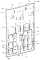
図1,図2に示すように、商品搬出装置10は、薄板鋼板製になる矩形平板状に形成されるとともに商品収納通路183(図16参照)に横倒し姿勢で一列に整列して収納されたロングサイズの商品の長さに対応する幅の基板1を備え、基板1の背面には、2組の第1ストッパ部材2,2A、2組の第2ストッパ部材3,3A、2組の下部リンクピン4,4Aおよび上部リンクピン5,5Aを支持する2組のリンク機構6,6Aと、単一のモータ駆動ユニット7と、2組のリンク機構6と6Aと単一のモータ駆動ユニット7とを連結する連結機構8と、切換手段9などが配設されている。なお、2組の第1ストッパ部材2,2A、第2ストッパ部材3,3A、下部リンクピン4,4Aおよび上部リンクピン5,5Aを支持するリンク機構6,6Aのうち一方の第1ストッパ部材2、第2ストッパ部材3、下部リンクピン4および上部リンクピン5を支持するリンク機構6のセットが、商品収納通路183(図16参照)に横倒し姿勢で前後方向に二列に整列して収納されたハーフサイズの商品の一方の列の商品搬出機構(以下、このセットを第1搬出機構と称する)を構成し、他方の第1ストッパ部材2A、第2ストッパ部材3A、下部リンクピン4Aおよび上部リンクピン5Aを支持するリンク機構6Aのセットが、前記ハーフサイズの商品の他方の列の商品搬出機構(以下、このセットを第2搬出機構と称する)を構成し、第1搬出機構の第1ストッパ部材2,第2ストッパ部材3,下部リンクピン4および上部リンクピン5を支持するリンク機構6と、第2搬出機構の第1ストッパ部材2A,第2ストッパ部材3,下部リンクピン4Aおよび上部リンクピン5Aを支持するリンク機構6Aとは同一の部材からなるものである。また、以下の説明で第2搬出機構に対応する部材には第1搬出機構を示す参照数字の後に参照符号の「A」を付してその説明を割愛する。
As shown in FIG. 1 and FIG. 2, the
前記基板1の左右フランジ1a,1b(図4参照)の上部には、ラック側板181,181(図16参照)に架設されたピン部材P,P(図10参照)と係合する係合部1aa,1bbを設け、また、基板1の上フランジ1cに上部側のピン部材Pに係合する係合部1ccを設ける一方、基板1の下フランジ1dに係合するホルダー9を設け、ホルダー9を下部側のピン部材Pに係合・切断させるように構成されている点は従来装置と同一である。なお、「左右」とは、基板1のフランジ1a〜1dが設けられた背面と反対側の面を正面として見た場合の「左右」を指す。
Engagement portions that engage with pin members P, P (see FIG. 10) installed on the
前記基板1には、図4にも示すように、下半領域の左右に開口部11(11A)が穿設される一方、基板1の上半領域がモータ駆動ユニット7の配設位置として形成されている。前記基板1に形成された左右の開口部11(11A)に臨んで軸受部12(12A)が設けられている。この軸受部12(12A)は、開口部11(11A)の左右方向の略中央部に位置している。
As shown in FIG. 4, the substrate 1 is provided with openings 11 (11A) on the left and right sides of the lower half region, while the upper half region of the substrate 1 is formed as a mounting position of the
前記軸受部12(12A)は、リンク機構6(6A)に支持された下部リンクピン4(4A)および上部リンクピン5(5A)の一端を支持するとともに第1ストッパ部材2(2A),第2ストッパ部材3に関わる共通の回動軸20(後述)の中央域を支持し、下部リンクピン4(4A)および上部リンクピン5(5A)の他端は、基板1の開口部11(11A)の左右縁に基板1の背面側に突出して形成されたフランジ14(14A)により支持されている。回動軸20の両端は、前記開口部11の左縁に基板1の背面側に突出して形成されたフランジ13(13A)と開口部11Aの右縁に基板1の背面側に突出して形成されたフランジ14Aにより支持されている。なお、軸受部12(12A)とフランジ13,14とにおける上記下部リンクピン4(4A)および上部リンクピン5(5A)を支持する構成はほぼ対称の構成であるので、以下の説明では、軸受部12(12A)について説明した後にフランジ13,14に係る構成について説明する。
The bearing portion 12 (12A) supports one end of the lower link pin 4 (4A) and the upper link pin 5 (5A) supported by the link mechanism 6 (6A), and also supports the first stopper member 2 (2A) and the first stopper member 2 (2A). 2 A central area of a common rotary shaft 20 (described later) related to the
前記軸受部12(12A)は、基板1に形成された開口部11(11A)における上縁と下縁とに一体的に連結されるとともに基板1の平板面により背面側に浮き上がるように形成され、開口部11(11A)を左右に二等分している。この軸受部12(12A)は、基板1における開口部11(11A)を形成する際に、その開口部11(11A)を左右に分断するように基板1の板面の一部を残して基板1に一体に形成されたものであり、背面側への折り曲げ部を重ね合わせて機械的強度の向上を図っている。前記軸受部12(12A)には、上下方向に延在する上下一対の長穴121,122(121A,122A)を設けている。軸受部12(12A)の上下一対の長穴121,122(121A,122A)のほぼ中間位置における正面側および背面側には円弧状に切り欠いた凹部(参照符号省略)が形成されている。この凹部のうち、正面側の凹部は回動軸20との干渉を避けるためのものであり、背面側の凹部は背中合わせに抱き合せて配設される他方の商品搬出装置(後述する図13参照)の回動軸20との干渉を避けるためのものである。なお、上下一対の長穴121,122(121A,122A)の穴周縁にはヘミング加工若しくはバーリング加工を施して回動軸との摩擦を低減するように構成されている。
The bearing portion 12 (12A) is integrally connected to the upper edge and the lower edge of the opening 11 (11A) formed in the substrate 1 and is formed so as to float to the back side by the flat surface of the substrate 1. , The opening 11 (11A) is divided into left and right parts. This bearing portion 12 (12A) leaves a part of the plate surface of the substrate 1 so as to divide the opening portion 11 (11A) into left and right when forming the opening portion 11 (11A) in the substrate 1. It is formed integrally with the first unit, and the bent portion on the back side is overlapped to improve the mechanical strength. The bearing 12 (12A) is provided with a pair of upper and lower elongated holes 121, 122 (121A, 122A) extending in the vertical direction. A concave portion (reference numeral omitted) cut out in an arc shape is formed on the front surface side and the rear surface side at a substantially middle position between the pair of upper and lower elongated holes 121, 122 (121A, 122A) of the bearing portion 12 (12A). Of these recesses, the front-side recess is for avoiding interference with the
前記開口部11(11A)の右縁に形成されたフランジ14(14A)には、前記軸受部12(12A)の上下一対の長穴121,122(121A,122A)に対応する長穴141,142(141A,142A)を設けている。また、前記フランジ14(14A)における上下一対の長穴141,142(141A,142A)のほぼ中間位置には支軸穴16(16A)が設けられ、前記開口部11(11A)の左縁に形成されたフランジ13(13A)には、前記フランジ14(14A)に設けた支軸穴16(16A)と同一線上に支軸穴15(15A)が設けられている。
The flange 14 (14A) formed on the right edge of the opening 11 (11A) has elongated
前記フランジ13(13A)に設けた支軸穴15(15A)と前記フランジ14(14A)に設けた支軸穴16(16A)は、第1ストッパ部材2(2A)と第2ストッパ部材3(3A)に共通の回動軸20を支持するものである。また、前記軸受部12(12A)に設けた長穴122(122A)と前記開口部11(11A)の右縁に形成されたフランジ14(14A)に設けた長穴142は、リンク機構6に支持された下部リンクピン4(4A)をそれぞれ上下方向にスライド移動可能に支持する一方、前記前記軸受部12(12A)に設けた長穴121(121A)と前記フランジ14(14A)に設けた長穴141(141A)は、リンク機構6に支持された上部リンクピン5(5A)をそれぞれ上下方向にスライド移動可能に支持するものである。なお、前記支軸穴16(16A)、長穴141,142(141A,142A)の穴周縁はヘミング加工若しくはバーリング加工を施して、下部リンクピン4(4A),上部リンクピン5(5A)との摩擦を低減するように構成されている。
The support shaft hole 15 (15A) provided in the flange 13 (13A) and the support shaft hole 16 (16A) provided in the flange 14 (14A) include a first stopper member 2 (2A) and a second stopper member 3 ( 3A) supports the
また、基板1の上下方向の中間位置には、左右方向に4個のガイド部17が形成されている。このガイド部17は、基板1を切り起こして形成されるとともに上下方向に延在するガイド溝171が設けられている。このガイド部17は、後述する連結機構8のスライドピン83を案内するものである。
Further, four
前記第1ストッパ部材2(2A)は、図2に示すように、基板1の開口部11(11A)の左右両縁に形成したフランジ13,14(13A,14A)の間に介在してあり、回動軸20に回動可能に支持されている。第1ストッパ部材2(2A)は、回動軸20を中心として回動して、基板1の開口部11(11A)から商品収納通路183(図16参照)にそれぞれ突出する突出位置と、開口部11(11A)を閉塞する態様で商品収納通路183から退く退避位置との間に移動可能である。回動軸20には、図3に示した捻りコイルばね30(30A)が巻装してある。第1ストッパ部材2(2A)は、捻りコイルばね30(30A)の弾性付勢力によって突出位置に向けて常に付勢されており、突出位置においてその表面(上面)が商品G(図11参照)を保持する保持部として形成されている。
As shown in FIG. 2, the first stopper member 2 (2A) is interposed between the
前記第1ストッパ部材2(2A)は、図5に示すように、平板状の保持部21(21A)の背面に2個の軸受部22(22A)を一体に形成した合成樹脂(たとえば、ポリアセタール)製になる。前記保持部21(21A)の基端側の左右両端には軸挿通穴250(250A)を有する左右一対の軸支部25(25A)が突出形成されるとともに左右一対の軸支部25(25A)の外方寄りに売切れ検出片26(26A)が形成されている。この軸支部25(25A)の軸挿通穴250(250A)は、回動軸20を挿通するためのものである。また、軸支部25(25A)は基板1の開口部11(11A)の左右両側に穿設した長穴101,102(101A,102A)に差し込んだうえで軸挿通穴250(250A)に回動軸20を挿通させるように構成されている。
As shown in FIG. 5, the first stopper member 2 (2A) is made of synthetic resin (for example, polyacetal) in which two bearing portions 22 (22A) are integrally formed on the back surface of a flat plate-shaped holding portion 21 (21A). ) Will be made. A pair of left and right shaft support portions 25 (25A) having shaft insertion holes 250 (250A) are formed at the left and right ends on the base end side of the holding portion 21 (21A), and the pair of left and right shaft support portions 25 (25A) are formed. A sold-out detection piece 26 (26A) is formed on the outer side. The shaft insertion hole 250 (250A) of the shaft support 25 (25A) is for inserting the
前記2個の軸受部22(22A)は、平板状の保持部21(21A)の左右方向の一方に片寄せて配設されている。この2個の軸受部22(22A)の左右方向の幅は、基板1の開口部11(11A)における軸受部12(12A)により二等分された開口(空間)幅よりも小さく当該空間を通過可能な寸法に定められ、保持部21(21A)の中央より左右のいずれか一方に片寄せて配設(図4では、開口部11(11A)における軸受部12(12A)と開口部11(11A)のフランジ14(14A)との間の開口(空間)に対応して配設)している。これは、2個の商品搬出装置を背中合わせに抱き合せた場合に、一方の商品搬出装置の第1ストッパ部材2(2A)と他方の商品搬出装置の第1ストッパ部材2(2A)が互いに干渉することがないようにするためである。2個の軸受部22(22A)の基端部側にはそれぞれ軸挿通穴220(220A)が設けられている。これらの軸挿通穴220(220A)は、回動軸20を挿通するためのものであり、保持部21(21A)の左右両端に形成した軸支部25(25A)の軸挿通穴250(250A)と同一軸線上に位置している。2個の軸受部22(22A)の基端部からは円弧状の係止突起23(23A)がそれぞれ突出して形成されている。また、2個の軸受部22(22A)の基端部からは円弧状のガイド突起24(24A)が形成されている。この円弧状のガイド突起24(24A)は、円弧状の係止突起23(23A)との間に、下部リンクピン4(4A)を案内する湾曲状の溝240(240A)を形成するように構成されている。
The two bearing portions 22 (22A) are arranged so as to be offset to one side in the left-right direction of the flat plate-shaped holding portion 21 (21A). The width of the two bearing portions 22 (22A) in the left-right direction is smaller than the width of the opening (space) that is bisected by the bearing portion 12 (12A) in the opening 11 (11A) of the substrate 1. The size is determined to be passable, and the holding portion 21 (21A) is arranged so as to be offset to the left or right side from the center (in FIG. 4, the bearing portion 12 (12A) and the opening portion 11 (11A) and the opening portion 11 (11A)). (11A) is provided corresponding to the opening (space) between the flange 14 (14A). This is because when two product unloading devices are tied back to back, the first stopper member 2 (2A) of one product unloading device and the first stopper member 2 (2A) of the other product unloading device interfere with each other. This is to avoid doing anything. Shaft insertion holes 220 (220A) are provided on the base end sides of the two bearing portions 22 (22A). These shaft insertion holes 220 (220A) are for inserting the
前記第1ストッパ部材2(2A)の軸受部22(22A)における係止突起23(23A)の先端は、下降した下部リンクピン4(4A)と当接して第1ストッパ部材2(2A)を商品収納通路183(183A)のに突出した突出位置にロックするものであり、下部リンクピン4(4A)が上昇すると前記ロックを解除して第1ストッパ部材2(2A)の退避位置へ向けての回動を許容するものである。この退避位置への移動の際に、下部リンクピン4(4A)が溝240(240A)に沿って摺動する。 The tip of the locking projection 23 (23A) in the bearing portion 22 (22A) of the first stopper member 2 (2A) comes into contact with the lowered lower link pin 4 (4A) so that the first stopper member 2 (2A) is removed. It locks at a projecting position projecting into the product storage passage 183 (183A), and when the lower link pin 4 (4A) rises, the lock is released to the retracted position of the first stopper member 2 (2A). Is allowed. During the movement to the retracted position, the lower link pin 4 (4A) slides along the groove 240 (240A).
前記第2ストッパ部材3(3A)は、図2に示すように基板1の開口部11(1A)の左右側縁に形成したフランジ13,14(13A,14A)の間に介在してあり、回動軸20に回動可能に支持してある。第2ストッパ部材3(3A)は、回動軸20を中心として回動して、基板1の開口部11(11A)から商品収納通路183に同期若しくは選択的に出没して商品収納通183の内側に突出する突出位置と、開口部11(11A)を閉塞する態様で商品収納通路183から退く退避位置との間に移動可能である。
The second stopper member 3 (3A) is interposed between the
前記第2ストッパ部材3(3A)は、図6に示すように合成樹脂(例えば、ポリアセタール)からなり、基端部側に形成された軸挿通孔310(310A)を備えた3個の軸支部31(31A)と、左右方向のいずれか一方に片寄せて配設(図6では左側に配設)されるとともに背面側に突出した2個のストッパ壁32(32A)と、先端側に形成されるとともに背面側に突出する2個の舌片330(330A)を有する商品の保持部33(33A)が一体成形されている。 As shown in FIG. 6, the second stopper member 3 (3A) is made of synthetic resin (for example, polyacetal), and has three shaft support portions including shaft insertion holes 310 (310A) formed on the base end side. 31 (31A), and two stopper walls 32 (32A) that are arranged in one of the left and right directions to be offset (disposed on the left side in FIG. 6) and project to the rear side, and are formed on the tip side. The product holding portion 33 (33A) having two tongue pieces 330 (330A) which are formed on the back side and are formed integrally with each other.
前記軸支部31(31A)の軸挿通孔310(310A)は、回動軸20を挿通するためのものである。この軸挿通孔310(310A)を備えた2個の軸支部31(31A)は、第1ストッパ部材2(2A)における2個の軸受部22(22A)位置をずらして分散して設けられている。
The shaft insertion hole 310 (310A) of the shaft support 31 (31A) is for inserting the
前記第2ストッパ部材3(3A)の2個のストッパ壁32(32A)は、左右方向の一方に片寄せて配設(図6では左側に配設)されている。この2個のストッパ壁32(32A)の左右方向の幅は、基板1の開口部11(11A)における軸受部12(12A)により二等分された開口(空間)幅よりも小さく当該空間を通過可能な寸法に定められ、図4では、基板1の開口部11(11A)における軸受部12(12A)と開口部11(11A)のフランジ14(14A)との間の開口(空間)を通過するように構成されている。これは、2個の商品搬出装置を背中合わせに抱き合せた場合に、一方の商品搬出装置の第2ストッパ部材3(3A)と他方の商品搬出装置の第2ストッパ部材3(3A)が互いに干渉することがないようにするためである。 The two stopper walls 32 (32A) of the second stopper member 3 (3A) are arranged so as to shift to one side in the left-right direction (on the left side in FIG. 6). The width of the two stopper walls 32 (32A) in the left-right direction is smaller than the width of the opening (space) that is bisected by the bearing portion 12 (12A) in the opening 11 (11A) of the substrate 1. The size is determined to allow passage, and in FIG. 4, the opening (space) between the bearing portion 12 (12A) in the opening 11 (11A) of the substrate 1 and the flange 14 (14A) of the opening 11 (11A) is defined. Is configured to pass. This is because when two product unloading devices are tied back to back, the second stopper member 3 (3A) of one product unloading device and the second stopper member 3 (3A) of the other product unloading device interfere with each other. This is to avoid doing anything.
前記2個のストッパ壁32(32A)は、凹状の摺動溝321(321A)と、この凹状の摺動溝321(321A)の溝壁に沿って形成されたストッパ面322(322A)を備えている。凹状の摺動溝321(321A)は、上部リンクピン5(5A)が摺動可能であり、第2ストッパ部材3(3A)が退避位置に退避した状態では上部リンクピン5(5A)を受容するように構成されている。前記ストッパ壁32(32A)のストッパ面322(322A)は、上部リンクピン5(5A)の上昇により上部リンクピン5(5A)が凹状の摺動溝321(321A)の溝壁に当接して第2ストッパ部材3(3A)が商品収納通路183に突出した際(上部リンクピン5(5A)が摺動溝321(321A)から抜け出した際)に上部リンクピン5(5A)と当接して第2ストッパ部材3(3A)を突出位置でロックするものである。 The two stopper walls 32 (32A) are provided with a concave sliding groove 321 (321A) and a stopper surface 322 (322A) formed along the groove wall of the concave sliding groove 321 (321A). ing. The concave slide groove 321 (321A) allows the upper link pin 5 (5A) to slide, and receives the upper link pin 5 (5A) when the second stopper member 3 (3A) is retracted to the retracted position. Is configured to. The stopper surface 322 (322A) of the stopper wall 32 (32A) is brought into contact with the groove wall of the sliding groove 321 (321A) in which the upper link pin 5 (5A) is concave due to the rise of the upper link pin 5 (5A). When the second stopper member 3 (3A) projects into the product storage passage 183 (when the upper link pin 5 (5A) comes out of the sliding groove 321 (321A)), the second stopper member 3 (3A) comes into contact with the upper link pin 5 (5A). The second stopper member 3 (3A) is locked at the protruding position.
前記第1ストッパ部材2(2A)および第2ストッパ部材3(3A)を軸支する回動軸20の基板1への組付けは、第1ストッパ部材2(2A)および第2ストッパ部材3(3A)を基板1の開口部11の所定位置に配設する。次いで、基板1の右フランジ1bの外側から当該右フランジ1bに形成した丸穴1b1に回動軸20の先端を差し込む。そして、開口部11Aのフランジ14Aに形成した支軸穴16A、開口部11Aのフランジ13Aに形成した支軸穴15A、開口部11のフランジ14に形成した支軸穴16、開口部11のフランジ13に形成した支軸穴15の順に挿通させる。この場合、第1ストッパ部材2(2A)の保持部21(21A)に設けた左右一対の軸支部25(25A)の軸挿通穴250(250A),第1ストッパ部材2(2A)の軸受部22(22A)に設けた軸挿通穴220(220A),第2ストッパ部材3(3A)の軸挿通孔310(310A)がフランジ13,14(13A,14A)に形成した支軸穴15,16(15A,16A)と一直線上に位置するように所定位置に配置されているので、第1ストッパ部材2(2A)と第2ストッパ部材3(3A)が回動軸20に軸支される。回動軸20の頭部には径外方向に張り出したストッパが設けられており、このストッパがフランジ14Aに当接するまで回動軸20は差し込まれる。なお、回動軸20は、基板1の右フランジ1bとフランジ14Aとの間に装着される配線カバーWC(図2参照)に頭部が当接することにより抜け止めが施される。
Assembling of the
前記リンク機構6(6A)は、連結機構8を介してモータ駆動ユニット7により駆動され、第1搬出機構および第2搬出機構の第1ストッパ部材2(2A)に対応して設けられるとともにそれぞれの第1ストッパ部材2(2A)を商品収納通路183に突出した突出位置と商品収納通路183から退避した退避位置とに移動させる第1搬出機構および第2搬出機構の下部リンクピン4(4A)と、第2ストッパ部材3(3A)に対応して設けられるとともにそれぞれの第2ストッパ部材3(3A)を商品収納通路183に突出した突出位置と商品収納通路183から退避した退避位置とに移動させる第1搬出機構および第2搬出機構の上部リンクピン5(5A)とを支持する態様で基板1に組み込まれたものである。
The link mechanism 6 (6A) is driven by the
前記リンク機構6(6A)は、図7に示すように、鋼板製のリンク部材60(60A)を備えている。リンク部材60(60A)は、短冊状の鋼板をコ字状に折り曲げて形成されている。リンク部材60(60A)のコ字状両脚片の上端には、後述する連結機構8のスライドピン83(83A)が貫通する挿通穴610(610A)を有する係止部61(61A)が形成されている。また、リンク部材60(60A)のコ字状両脚片の下端には、下部リンクピン4(4A)が貫通する係合穴620(620A)を有する支持部62(62A)が形成されている。さらに、リンク部材60(60A)のコ字状両脚片における前記支持部62(62A)の上方には、上部リンクピン5(5A)が貫通する係合穴630(630A)を有する支持部63(63A)が形成されている。前記支持部62(62A)は、下部リンクピン4(4A)を支持してリンク部材60(60A)の上下動作に連動して当該下部リンクピン4(4A)を上下方向に移動させるものである。前記支持部63(63A)は、上部リンクピン5(5A)を支持してリンク部材60(60A)の上下動作に連動して当該上部リンクピン5(5A)を上下方向に移動させるものである。また、前記リンク部材60(60A)の下方には、図2に示した捻りコイルばねからなる復帰ばね64(64A)の一端(上端)が係止される。この復帰ばね64(64A)の他端(下端)は、基板1の下フランジ1dに係止されている。
As shown in FIG. 7, the link mechanism 6 (6A) includes a steel plate link member 60 (60A). The link member 60 (60A) is formed by bending a strip-shaped steel plate into a U-shape. A locking portion 61 (61A) having an insertion hole 610 (610A) through which a slide pin 83 (83A) of the connecting
前記上部リンクピン5(5A)および下部リンクピン4(4A)の基板1への組付けは、リンク部材60(60A)を基板1の開口部11(11A)の所定位置、すなわち、図3に示した基板1の開口部11(11A)における軸受部12(12A)と開口部11(11A)のフランジ14(14A)との間の開口(空間)位置に配設したうえで、上部リンクピン5(5A)および下部リンクピン4(4A)を基板1に装着する。この場合、上部リンクピン5,下部リンクピン4は、基板1の開口部11の右側のフランジ14の外側(図4ではフランジ14の左側)からフランジ14に形成した長穴141,142を介して軸受部12に形成した長穴121,122の順に挿通させる。そして、上部リンクピン5,下部リンクピン4に設けた頭部のストッパ51,41が基板1のフランジ14に当接するまで差し込むことにより、上部リンクピン5,下部リンクピン4がリンク部材60に形成した支持部63,62に支持された状態で基板1に組付けられる。一方、上部リンクピン5A,下部リンクピン4Aは、基板1の右フランジ1bの外側から当該右フランジ1bに形成した丸穴1b2,1b3にそれぞれの一端を差し込む。次いで、上部リンクピン5A,下部リンクピン4Aを、基板1の開口部11Aの右側のフランジ14Aに形成した長穴141A,142Aを介して軸受部12Aに形成した長穴121A,122Aの順に挿通させる。そして、上部リンクピン55A,下部リンクピン4Aに設けた頭部のストッパ51A,41Aが基板1のフランジ14Aに当接するまで差し込むことにより、上部リンクピン5A,下部リンクピン4Aがリンク部材60Aに形成した支持部63A,62Aに支持された状態で基板1に組付けられる。なお、上部リンクピン5(5A)および下部リンクピン4(4A)は、基板1に装着される配線カバーWC(図2参照)により抜け止めが施される。
To assemble the upper link pin 5 (5A) and the lower link pin 4 (4A) to the substrate 1, the link member 60 (60A) is attached to a predetermined position of the opening 11 (11A) of the substrate 1, that is, as shown in FIG. The upper link pin is arranged at the opening (space) position between the bearing portion 12 (12A) in the opening 11 (11A) of the substrate 1 and the flange 14 (14A) of the opening 11 (11A) shown. 5 (5A) and the lower link pin 4 (4A) are mounted on the substrate 1. In this case, the
前記連結機構8は、リンク機構6(6A)とモータ駆動ユニット7とを連結するものであり、切換手段9により前記リンク機構(6A)との連結を選択的に接続・切断されることによりリンク機構6(6A)を同期して駆動、或いは前記リンク機構6(6A)の一方または他方を個別に駆動するものである。
The
前記連結機構8は、図7に示すように、連結部材80とスライドピン83(83A)からなる。連結部材80は鋼板製になり、その上端に、図2に示す前記モータ駆動ユニット7のリンクレバー75(75A)に係合する係合片81が形成されている。また、連結部材80の下端には切換手段9を把持する把持部82を有している。把持部82は切換手段9のフレーム91を両側から挟むように係止するフック状の係止爪821,822(図8も参照)を有している。この連結部材80は基板1に上下方向にスライド移動自在に取着されている。また、把持部82には捻りコイルばねからなる復帰ばね84(84A)の一端(上端)が係止される。この復帰ばね84(84A)の他端(下端)は、基板1を切り起こして形成された係止片1eに係止されている。
As shown in FIG. 7, the connecting
前記スライドピン83(83A)は磁性体により形成された棒状体からなり、後述するソレノイド90(90A)の可動鉄心を構成する。スライドピン83(83A)にはピン径よりも一回り大きなリング状の位置決め突起830(830A)が形成されている。前記スライドピン83(83A)は、リンク部材60の上端の係止部61に形成された挿通穴610を貫通してリンク部材60に連結されるとともに基板1に形成した4個のガイド部17のうちの左右2個のガイド溝171にそれぞれガイドされて左右方向にスライド移動可能である。
The slide pin 83 (83A) is a rod-shaped body made of a magnetic material and constitutes a movable iron core of a solenoid 90 (90A) described later. The slide pin 83 (83A) is formed with a ring-shaped positioning protrusion 830 (830A) which is slightly larger than the pin diameter. The slide pin 83 (83A) penetrates through the
前記スライドピン83(83A)の基板1への組付けは、前述したリンク部材60(60A)を基板1の開口部11(11A)の所定位置に配設したうえで、基板1に装着される。すなわち、スライドピン83は、その先端(図7では左端)を、基板1に形成したガイド部17(図4では右端のガイド部17)のガイド溝171に対峙させる態様でスライドピン83の胴部を基板1のフランジ1aに形成された切欠き1a1に嵌め込む。この状態でスライドピン83を前記ガイド部17のガイド溝171を貫通させたうえでスライドピン83の先端が前記ガイド部17に隣接するガイド部17(図3では右から2番目のガイド部17)のガイド溝171に到達するまで差し込む。この状態でスライドピン83は2個のガイド部17のガイド溝171に保持されるとともにリンク部材60の上端の係止部61に形成された挿通穴610を貫通してリンク部材60に連結される(図示は省略したがスライドピン83の差し込み方向とは逆方向への抜け止めが施されるものである)。一方、スライドピン83Aは、その先端(図7では右端)を、基板1に形成したガイド部17(図3では左端のガイド部17)のガイド溝171に対峙させる態様でスライドピン83の胴部を基板1のフランジ1bに形成された切欠き1b4に嵌め込む。この状態でスライドピン83を前記ガイド部17のガイド溝171を貫通させたうえでスライドピン83の先端が前記ガイド部17に隣接するガイド部17(図4では左から2番目のガイド部17)のガイド溝171に到達するまで差し込む。この状態でスライドピン83は2個のガイド部17のガイド溝171に保持されるとともにリンク部材60Aの上端の係止部61Aに形成された挿通穴610Aを貫通してリンク部材60Aに連結される(図示は省略したがスライドピン83Aの差し込み方向とは逆方向への抜け止めが施されるものである)。
The slide pin 83 (83A) is assembled to the board 1 after the link member 60 (60A) described above is arranged at a predetermined position of the opening 11 (11A) of the board 1. . That is, the
前記連結部材80の把持部82に把持された切換手段9は、前記連結機構8の連結部材81と一対のスライドピン83(83A)とを接続・切断させるものであり、前記連結機構8の連結部材81と一対のスライドピン83(83A)との連結を接続・切断するように構成されている。この切換手段9は、前記連結機構8の連結部材81と一対のスライドピン83(83A)との連結を接続することにより、連結機構8とリンク機構6(6A)とを連結し、連結部材81と一対のスライドピン83(83A)とを選択的に接続・切断させることにより連結機構8とリンク機構6(6A)の一方または他方とを連結若しくは連結を切断する。
The switching means 9 gripped by the
前記切換手段9は、図8に示すように、ソレノイド90(90A)からなる。ソレノイド90(90A)は、有底円筒状の固定鉄心にコイルを巻回してなるものであり、非磁性体のフレーム91に装着されている。フレーム91は、中央の仕切壁911より左右にソレノイド90(90A)の収納空間を形成し、当該収納空間の周囲が断面コ字状に形成されている。ソレノイド90(90A)は、固定鉄心の有底部をフレーム91の仕切壁911に当接させ、固定鉄心の開口部が逆方向を向いてフレーム91から露出する態様でフレーム91の収納空間に装着されている。ソレノイド90(90A)の固定鉄心の円筒部の径は、連結部材8のスライドピン83(83A)の径よりも僅かに大きく、そのスライドピン83(83A)を受容可能な大きさに定められている。また、ソレノイド90(90A)の固定鉄心の底部には捻りコイルばねからなる復帰ばね92(92A)が設けられている。
The switching means 9 comprises a solenoid 90 (90A) as shown in FIG. The solenoid 90 (90A) is formed by winding a coil around a fixed iron core having a bottomed cylindrical shape, and is mounted on the
前記切換手段9の連結部材80の把持部82への組付けは、フレーム91のコ字状底面を把持部82の板面に当接させる態様で把持部82に嵌め込む。この嵌め込みの際、フレーム91のコ字状底面の左右縁が把持部82の両端に設けたフック状の係止爪821,822に当接するが、さらにフレーム91を嵌め込むとフック状の係止爪821,822が外側に撓んでフレーム91のコ字状底面の進入を許容し、フレーム91のコ字状底面の左右縁が係止爪821,822のフックを通過すると係止爪821,822が復元してフックによりフレーム91のコ字状底面の左右縁が係止される。これにより、切換手段9が連結部材80の把持部82に一体的に組付けられる。
When the switching
ここで、前記切換手段9が一体的に組付けられた連結部材80およびスライドピン83(83A)を基板1の所定位置に組付けた状態(待機状態)では、スライドピン83(83A)の軸線と、ソレノイド90(90A)の可動鉄心の中心線とが一致するように構成されている。また、スライドピン83(83A)は、ソレノイド90(90A)の可動鉄心から離隔している、そして、前記連結機構8のスライドピン83(83A)は、ソレノイド90(90A)の可動鉄心を構成するものであって磁性体により形成されている。したがって、ソレノイド90(90A)のコイルへ通電して励磁すると可動鉄心としてのスライドピン83(83A)がソレノイド90(90A)の固定鉄心に吸引されて固定鉄心の円筒部内(収納空間)に進入してソレノイド90(90A)とスライドピン83(83A)とが一体的に結合される。この場合、復帰ばね92(92A)はスライドピン83(83A)に押圧されて復元力を蓄える。ソレノイド90(90A)のコイルへの通電を切断して非励磁状態(釈放)となると、復帰ばね92(92A)に蓄えられた復元力によりスライドピン83(83A)がソレノイド90(90A)の固定鉄心の円筒部から押し出されてソレノイド90(90A)から離隔する。このように、ソレノイド90(90A)の励磁によりスライドピン83(83A)を吸引して連結機構8と前記リンク部材60(60A)との接続させることによって、モータ駆動ユニット7からの駆動力が前記リンク部材60(60A)に同時に伝達されて2組の第1ストッパ部材2(2A)および第2ストッパ部材3(3A)を同期して駆動ことが可能となり、また、ソレノイド90(90A)によりスライドピン83(83A)の一方または他方を吸引してスライドピン83(83A)の一方または他方との接続する一方、ソレノイド90(90A)の釈放によりスライドピン83(83A)の他方または一方を離隔させてスライドピン83(83A)の他方または一方との連結を解除することによって、モータ駆動ユニット7からの駆動力が前記リンク部材60(60A)の一方または他方に個別に伝達されて2組の第1ストッパ部材および第2ストッパ部材の一方または他方を個別に駆動することが可能となる。
Here, in a state (standby state) in which the connecting
前記モータ駆動ユニット7は、商品選択ボタンの操作に基づく販売指令によりユニットケース70(図3参照)に内蔵したモータ71(図9参照)が正転若しくは逆転駆動され、このモータ71の回転によりリンクレバー75(75A)介してリンク部材60(60A)を選択的に上昇させるものである。ユニットケース70はベース部材とカバー部材とからなり、その内部に、図9に示すような、モータ71,歯車伝達機構72,出力歯車73,キャリアスイッチ74,リンクレバー75(75A)などを内蔵している。このモータ駆動ユニット7は、ユニットケース70におけるベース部材の背面に突出形成した複数のボス(不図示)を基板1の平板面に穿設した穴1fに嵌合させる一方、ベース部材の側面に設けた突起(不図示)を基板1の平板面に切り起こして形成した係止フック1g,1hに係止させることにより基板1に組付けられる。
In the
モータ駆動ユニット7のユニットケース70に内蔵したモータ71は、販売指令に応じて正転若しくは逆転する正逆回転可能な直流モータであり、ユニットケース70のベース部材に保持されている。
The
歯車伝達機構72は、ウオーム721aとウオームホイール721bからなるウオーム歯車721および中間歯車722を備えて構成されている。ウオーム歯車721のウオーム721aは、モータ71の出力軸に取り付けられている。ウオームホイール721bは、ウオーム721aに噛み合う第1ホイールと、中間歯車722に噛み合う第2ホイールとが上下方向に段違いに設けられている。中間歯車722は、前記ウオームホイール721bの第2ホイールと噛み合う第1中間歯車と、出力歯車73に噛み合う第2中間歯車とが上下方向に段違いに設けられている。ウオーム歯車721および中間歯車722は、ユニットケース70のベース部材とカバー部材の軸受部により回転可能に配設される。
The
前記出力歯車73は、中間歯車722の第2中間歯車と噛み合うホイールとして形成され、その一方の板面(上面)にカムと突起731が形成され、他方の板面(背面)にキャリアスイッチ74を制御する押圧片(図9では見えない)が形成されている。カムと突起731は、出力歯車73の板面から離隔する方向に突出する態様で円弧状に形成されている。このカムと突起731は、その円弧状の長さがリンク部材60(60A)を上昇させた後に所定時間の間その状態を保持するのに十分な長さとなるように形成されている。キャリアスイッチ74を制御する押圧片は、カムと突起731の反対側の板面に位置して板面から離隔する方向に突出する態様で略V字状に形成されており、図9の(a)の状態でキャリアスイッチ74の接触子を押圧するように形成されている。この出力歯車73は、ユニットケース70のベース部材とカバー部材の軸受部により回転可能に配設される。
The
キャリアスイッチ74は、いわゆる押しボタンスイッチであり、接触子(不図示)を備えている。このキャリアスイッチ74は、出力歯車73よりも僅かに上方域にユニットケース70のベース部材に保持された状態で配設されている。このキャリアスイッチ74は、接触子が出力歯車73の押圧片に押圧されるとオン状態となる一方、出力歯車73の押圧片が離れて接触子が押圧されない場合にはオフ状態となるものであり、販売指令により駆動されたモータ71を、出力歯車73が一回転するように制御するためのものである。
The
リンクレバー75(75A)は樹脂成型品になり、基部751(751A)を貫通するユニットケース70のカバー部材に設けたレバー軸700(700A)に回転可能に軸支されている。リンクレバー75(75A)の先端部752(752A)は、ユニットケース70のベース部材とカバー部材を切り欠いて形成した開口(不図示)から外部に突出する態様で上方に湾曲したフック状を成している。リンクレバー75(75A)の基部751(751A)に設けられた係止片753(753A)は、基部751(751A)の後方側より後方に向けて延在する弾性変形可能な板状の弾性部材である。係止片753(753A)は、その自由端がカバー部材に設けた突出片(不図示)に当接することにより常態におけるリンクレバー75(75A)の待機姿勢を、図9の(a)に示す位置に決めている。
The link lever 75 (75A) is a resin molded product, and is rotatably supported by a lever shaft 700 (700A) provided on a cover member of the
係る構成のモータ駆動ユニット7を備えた商品搬出装置は、本件出願人から特願2013−236105号(特開2015−95235号公報)として出願されている。
The product unloading device provided with the
前記売切検出スイッチ18(18A)は、基板1に装着される配線カバーWC(図2,図3参照)に係止固定されたマイクロスイッチからなる。この売切検出スイッチ18(18A)は第1ストッパ部材2(2A)に設けた売切れ検出片26(26A)にマイクロスイッチの接触子が当接するように配設され、第1ストッパ部材2(2A)が商品収納通路183に最大開度に突出した状態を検知するように構成されている。すなわち、第1ストッパ部材2(2A)は捻りコイルばね30(30A)の弾性付勢力によって突出位置に向けて常に付勢されており、商品を保持していない状態で商品収納通路183に突出した際に最大開度となり、最大開度に突出した第1ストッパ部材2(2A)に商品が落下すると商品収納通路183から退避する方向に僅かに回動した後、第1ストッパ部材2(2A)の軸受部22(22A)における係止突起23(23A)の先端が、下降した下部リンクピン4(4A)と当接して第1ストッパ部材2(2A)を商品収納通路183に突出した突出位置にロックし、ロック状態における第1ストッパ部材2(2A)の開度が最大開度よりも小さくなるように構成されている。そこで、売切検出スイッチ18(18A)は、第1ストッパ部材2(2A)が最大開度に突出した際、第1ストッパ部材2(2A)に設けた売切れ検出片26(26A)がマイクロスイッチの接触子に当接してオン状態となり、最大開度に突出した第1ストッパ部材2(2A)に商品が落下して当該第1ストッパ部材2(2A)が商品収納通路183から退避する方向に僅かに回動した後ロックされるまでの間に第1ストッパ部材2(2A)に設けた売切れ検出片26(26A)がマイクロスイッチの接触子から離隔してオフ状態となるように構成されている。なお、売切検出スイッチ18(18A)からの信号を処理する制御部では、売切検出スイッチ18(18A)からのオン信号が所定時間継続した場合に「売切れ」として判断する処理が行われる。
The sold-out detection switch 18 (18A) is composed of a micro switch locked and fixed to the wiring cover WC (see FIGS. 2 and 3) mounted on the substrate 1. The sold-out detection switch 18 (18A) is arranged so that the contact of the micro switch contacts the sold-out detection piece 26 (26A) provided on the first stopper member 2 (2A). ) Is configured to detect a state in which the item) protrudes to the maximum opening degree in the
前記配線カバーWCは合成樹脂製になり、売切検出スイッチ18(18A)を係止するとともに基板1の左右方向の一方(図2の場合には左側)に片寄せて配設され、モータ駆動ユニット7のモータ71,キャリアスイッチ74、ソレノイド90(90A)、売切検出スイッチ18(18A)の配線を保護するものである。なお、配線カバーWCには、基板1の下フランジ1dに係止されるホルダー19(図2参照)が一体的に形成されている。このホルダー19は、商品収納ラック180に架設された下方のピン部材P(図10参照)に係合するフック19aを備えた周知のものである。
The wiring cover WC is made of synthetic resin, and is used to lock the sold-out detection switch 18 (18A) and to be offset to one of the left and right sides of the substrate 1 (left side in the case of FIG. 2) to drive the motor. The wiring of the
かかる構成の自動販売機の商品搬出装置10の動作について図10〜図12に基づいて説明する。図10は商品をローディングする前の商品搬出装置の側面断面図、図11は商品ローディング後における商品搬出装置の販売待機状態を示す動作説明図、図12は商品搬出装置の商品搬出時の動作説明図である。なお、以下の説明ではロングサイズの商品を販売する場合であって、前記切換手段9のソレノイド90(90A)の励磁によりスライドピン83(83A)を吸引して前記連結機構8と前記リンク部材60(60A)との連結を接続し、2組の第1ストッパ部材2(2A)および第2ストッパ部材3(3A)を同期して駆動する場合の動作を示し、また、290は、商品搬出装置2(2A)と商品収納通路183を挟んで対向配置された出口調整板である。
The operation of the
図10に示すように、商品搬出装置10は、商品がローディングされる前の状態では第1ストッパ部材2(2A)が商品収納通路183に突出し、第2ストッパ部材3(3A)が商品収納通路183から退避している。この場合、モータ駆動ユニット7の出力歯車73のカム突起731が最も上方に位置している(図9の(a)参照)。また、出力歯車73の背面に設けたキャリアスイッチ74用の押圧片が最も上方に位置してキャリアスイッチ74がオン状態にある。これにより、モータ71が停止しており、リンクレバー75(75A)の先端部752(752A)がリンク部材60(60A)の係止部61(61A)から下方に離隔した位置にある。このため、リンク部材60(60A)は復帰ばね64(64A)の付勢力により下降した状態にある。また、第1ストッパ部材2(2A)は、捻りコイルばね30(30A)の付勢力によって商品収納通路183に最大開度に開いた突出位置にある。そして、下降したリンク部材60(60A)に支持された下部リンクピン4(4A)が第1ストッパ部材2(2A)の係止突起23(23A)の先端の旋回軌跡線上に位置している。このように、第1ストッパ部材2(2A)が最大開度に開いた状態では売切検出スイッチ18(18A)がオン状態となる。一方、第2ストッパ部材3(3A)は下降したリンク部材60(60A)に支持された下部リンクピン4(4A)を第2ストッパ部材3(3A)の凹状の摺動溝321(321A)に受け入れて退避位置に復帰している。
As shown in FIG. 10, in the
斯様な待機状態において、最初にローディングされた商品は、最大開度に開いて突出位置にある第1ストッパ部材2(2A)の上に落下する。商品が落下することにより第1ストッパ部材2(2A)は退避位置に向けて僅かに回動する。この回動により第1ストッパ部材2(2A)の係止突起23(23A)の先端が下部リンクピン4(4A)に当接すると第1ストッパ部材2(2A)が商品を保持して最大開度よりも小さな開度で商品収納通路183に突出した状態にロックされ、第1ストッパ部材2(2A)に保持された商品が販売順位一番の商品(販売商品G1)となる。このように、第1ストッパ部材2(2A)が最大開度よりも小さな開度で商品収納通路183(183A)に突出した状態にロックされると、第1ストッパ部材2(2A)に設けた売切れ検出片26(26A)が売切検出スイッチ18(18A)のマイクロスイッチの接触子から離隔して売切検出スイッチ18(18A)がオフ状態となる。次にローディングされる商品は、第1ストッパ部材2(2A)により保持された販売商品G1の上に積み重ねられて次販売商品G2となり、引き続いてローディングされる商品(G3)は、次販売商品G2の上に順次積み重ねられる(図11参照)。
In such a standby state, the first loaded product drops to the maximum opening and drops onto the first stopper member 2 (2A) at the protruding position. When the product falls, the first stopper member 2 (2A) slightly rotates toward the retracted position. By this rotation, when the tip of the locking projection 23 (23A) of the first stopper member 2 (2A) comes into contact with the lower link pin 4 (4A), the first stopper member 2 (2A) holds the product and opens to the maximum. The product held in the first stopper member 2 (2A) and locked in a state in which it projects into the
商品選択ボタンの操作に基づく販売指令が与えられた場合、モータ駆動ユニット7に内蔵されたモータ71が正転駆動され、歯車伝達機構72を介して出力歯車73が、図9において、時計回りの方向に回転する。出力歯車73が反時計回りの方向に回転すると、出力歯車73の背面に設けた押圧片がキャリアスイッチ74の接触子から切断してキャリアスイッチ74がオフ状態となり、次にキャリアスイッチ74がオン状態となるまで(すなわち、出力歯車73が一回転するまでの期間)モータ71を正転駆動させる。出力歯車73の時計回りの方向への回転によりカム突起731がリンクレバー75の基端部751に上方より当接すると、リンクレバー75は、図9において反時計回りの方向に回転する。このリンクレバー75の反時計回りの方向への回転により、その先端部752が連結機構8を構成する連結部材80の係合片81に当接して連結部材80が上方にスライド移動する。この場合、前記切換手段9を構成するソレノイド90(90A)の励磁により連結機構8のスライドピン83(83A)を吸引して前記連結部材80と前記スライドピン83(83A)とが一体的に結合されているので、連結部材80とリンク部材60(60A)とがスライドピン83(83A)を介して連結されている。したがって、連結部材80が上方にスライド移動するとリンク部材60(60A)が復帰ばね64(64A)の付勢力に抗して上昇する。そして、カム突起731がリンクレバー75の基端部461aに摺接している間は、リンク部材60(60A)が上昇した状態に保持される。
When a sales command based on the operation of the product selection button is given, the
このリンク部材60(60A)の上昇に伴ってリンク部材60(60A)に結合された下部リンクピン4(4A)も上昇し、当該下部リンクピン4(4A)により商品収納通路183への突出位置にロックされた第1ストッパ部材2(2A)のロックが解除される。これにより、第1ストッパ部材2(2A)は、商品の荷重を受けて商品収納通路183から退避位置に向けて移動を開始する。第1ストッパ部材2(2A)が商品収納通路183から退避した退避位置へ移動すると販売商品G1は第1ストッパ部材2(2A)をすり抜けて下方に搬出される。販売商品G1が第1ストッパ部材2(2A)をすり抜けると、第1ストッパ部材2(2A)は捻りコイルばね30(30A)の付勢力によって突出位置に向けて移動を開始した後、最大開度に開いた状態で商品収納通路183に突出した突出位置に復帰する。
As the link member 60 (60A) rises, the lower link pin 4 (4A) coupled to the link member 60 (60A) also rises, and the lower link pin 4 (4A) projects to the
前記リンク部材60(60A)の上昇に伴って上昇する下部リンクピン4(4A)と同時に第2ストッパ部材3(3A)における凹状の摺動溝321(321A)に受け入れた上部リンクピン5(5A)も上昇する。これにより第2ストッパ部材3(3A)は、待機位置から商品収納通路183へ突出する突出位置へ向けて押し出される。そして、上部リンクピン5(5A)が第2ストッパ部材3(3A)のストッパ壁32(32A)に形成されたストッパ面322(322A)に対峙する位置まで上昇すると当該ストッパ面322(322A)に当接して第2ストッパ部材3(3A)の商品収納通路183から退避する退避位置への移動を規制する。そして、商品収納通路183に突出した突出位置に移動した第2ストッパ部材3(3A)は、販売商品G1が搬出されることにより下方に移動する次販売商品G2の下部に当接して保持し、次販売商品G2が下方に向けて移動するのを規制する。
The upper link pin 5 (5A) received in the concave sliding groove 321 (321A) of the second stopper member 3 (3A) at the same time as the lower link pin 4 (4A) that rises as the link member 60 (60A) rises. ) Also rises. As a result, the second stopper member 3 (3A) is pushed out from the standby position toward the projecting position projecting into the
このようなリンク部材60(60A)の上昇により下部リンクピン4(4A)による第1ストッパ部材2(2A)のロックを解除させて第1ストッパ部材2(2A)の退避位置への移動を許容して販売商品G1を払い出す一方、第2ストッパ部材3(3A)を退避位置から突出位置に移動させて次販売商品G2を保持する動作は、出力歯車73のカム突起731がリンクレバー75の基端部751に摺接している所定時間の間に実行される。
Such a rise of the link member 60 (60A) releases the lock of the first stopper member 2 (2A) by the lower link pin 4 (4A) and allows the movement of the first stopper member 2 (2A) to the retracted position. Then, the second stopper member 3 (3A) is moved from the retracted position to the projecting position to hold the next sale product G2 while the sale product G1 is discharged, and the
そして、出力歯車73の回転によりカム突起731とリンクレバー75の基端部751との当接が解除されると、復帰ばね64(64A)の付勢力によりリンク部材60(60A)は下降する。このリンク部材60(60A)の下降に伴ってリンク部材60(60A)に支持された上部リンクピン5(5A)および下部リンクピン4(4A)が下降する。第2ストッパ部材3(3A)におけるストッパ面322(322A)に当接した上部リンクピン5(5A)が下降すると第2ストッパ部材3(3A)は次販売商品G2により押圧されて商品収納通路183から退避する退避位置に向けて移動する。この第2ストッパ部材3(3A)の退避位置への移動により第2ストッパ部材3(3A)に保持された次販売商品G2が下方に移動を開始する。一方、下部リンクピン4(4A)は、突出位置に復帰している第1ストッパ部材2(2A)の円弧状の係止突起23(23A)の旋回軌跡線と交差する位置まで下降して待機する。この後、次販売商品G2が最大開度に開いた第1ストッパ部材2(2A)の上に落下すると第1ストッパ部材2(2A)は退避位置に向けて移動し、第1ストッパ部材2(2A)の円弧状の係止突起23(23A)が下降した下部リンクピン4(4A)に当接すると次販売商品G2を販売商品として保持した状態で突出位置にロックされる。その後、出力歯車73の回転によりカム突起731が待機状態の位置に戻ると、キャリアスイッチ74の接触子が押圧片により押圧されてキャリアスイッチ74がオン状態となる。これによりモータ71の駆動が停止されて待機状態に復帰する。
Then, when the contact between the
なお、出力歯車73の時計回りの方向への回転によりカム突起731とリンクレバー75の基端部751との当接が解除された後、出力歯車73のカム突起731が待機状態の位置に戻る途中において、カム突起731がリンクレバー75Aの基端部751Aに当接するが、弾性部材からなる係止片753Aが弾性変形してリンクレバー75Aの回動を許容することによりカム突起731は移動を阻止されることなく復帰位置に復帰する。リンクレバー75Aはカム突起731が通過することにより係止片753Aの作用により図9の(a)の待機姿勢に復帰する。
The rotation of the
上記ではロングサイズの商品を販売する場合の商品搬出装置10の動作について説明したが、ハーフサイズの商品を販売する場合には、前記切換手段9における2個のソレノイド90(90A)を選択的に励磁・釈放させる。商品搬出装置10における第1搬出機構(第1ストッパ部材2、第2ストッパ部材3、下部リンクピン4および上部リンクピン5を支持するリンク機構6のセットからなる搬出機構)を駆動してハーフサイズの商品を販売する場合には、前記切換手段9における2個のソレノイド90(90A)のうちの第1搬出機構に対応するソレノイド(ソレノイド90)を励磁する一方、第2搬出機構(第1ストッパ部材2A、第2ストッパ部材3A、下部リンクピン4Aおよび上部リンクピン5Aを支持するリンク機構6Aのセットからなる搬出機構)に対応する他方のソレノイド(ソレノイド90A)を非励磁状態とする。第1搬出機構に対応するソレノイド90が励磁されるとスライドピン83が吸引されてソレノイド90の固定鉄心の収納空間に、復帰ばね92を圧縮しつつ引き込まれてソレノイド90とスライドピン83とが一体的に結合される。これにより、連結機構8の連結部材80とスライドピン83とが接続されて第1搬出機構のリンク機構6が連結部材80と連結されてモータ駆動ユニット7の駆動力が伝動されることになる。一方、第2搬出機構に対応するソレノイド9Aは非励磁状態にあるので、スライドピン83Aがソレノイド9Aの固定鉄心から離隔しており、連結部材80から切り離されている。これにより、第2搬出機構のリンク機構6Aが連結部材80から切り離されてモータ駆動ユニット7からの駆動力は伝動されることがない。したがって、モータ駆動ユニット7が駆動されると第1搬出機構が、前述した販売動作と同様に駆動されてハーフサイズの商品が搬出される。その後、モータ駆動ユニット7の出力歯車73の回転によりカム突起731が待機状態の位置に戻ると、キャリアスイッチ74の接触子が押圧片により押圧されてキャリアスイッチ74がオン状態となる時点でソレノイド9への通電を切断して非励磁とする。これによりソレノイド9の固定鉄心の収納空間に引き込まれていたスライドピン83Aが復帰ばね92Aにより押し出されるようにスライド移動して連結部材80から切り離されて待機状態に復帰する。なお、第2搬出機構を駆動してハーフサイズの商品を搬出する場合には、第2搬出機構に対応するソレノイド9Aを励磁する一方、第1搬出機構に対応するソレノイド9は非励磁状態とする。
The operation of the product carry-out
図13は、図1乃至図9に示した商品搬出装置10と他の商品搬出装置とを背中合わせに抱き合せてなる商品搬出装置を示す斜視図である。図13において、図1乃至図9に示すものと同一のものには同一の符号を付してその説明を省略する。
FIG. 13 is a perspective view showing a product unloading device in which the
図13において、10で再び商品搬出装置を示し、10Aは商品搬出装置10と背中合わせに抱き合せて用いられる商品搬出装置を示す。ここで、商品搬出装置10Aの構成部材は、商品搬出装置10からモータ駆動ユニット7を除いた残りの構成部材と同一であり、商品搬出装置10Aの背面斜視図を図14に示している。図14に示した商品搬出装置10Aの背面斜視図と図2に示した商品搬出装置10の背面斜視図とを対比すると理解できるように、商品搬出装置10Aの構成部材の配置は商品搬出装置10からモータ駆動ユニット7を除去した構成部材の配置と同一であり、第1ストッパ部材2(2A)の2個の軸受部22(22A)および第2ストッパ部材3(3A)の2個のストッパ壁32(32A)を左右方向の一方に片寄せて配設していることにより、商品搬出装置10と商品搬出装置10Aとを背中合わせに抱き合せた場合にも、互いの第1ストッパ部材2(2A)の2個の軸受部22(22A)および第2ストッパ部材3(3A)の2個のストッパ壁32(32A)が干渉することはない。また、第1ストッパ部材2(2A)の2個の軸受部22(22A)の基端部から突出した円弧状の係止突起23(23A)が突出形成されて商品搬出の際に基板1の背面側に張り出すようになるが、この係止突起23(23A)は、互いの基板1の開口部11(11A)の空き領域に張り出すので、係止突起23(23A)の張り出しが妨げられることはない。なお、商品搬出装置10Aの連結機構8を構成する連結部材80の係止片81は、商品搬出装置10のモータ駆動ユニット7のリンクレバー75A(図9参照)に係合し、モータ駆動ユニット7のモータ71を逆転駆動することにより商品搬出装置10Aの第1搬出機構,第2搬出機構が切換手段9の作用によって同時に駆動、若しくは個別に駆動されるものである。
In FIG. 13,
前述したように、本発明の実施の形態に係る自動販売機の商品搬出装置によれば、ロングサイズの商品を横倒し姿勢で一列に整列して収納する一方、ハーフサイズの商品を横倒し姿勢で左右方向に二列に整列して収納する商品収納通路183の出口の近傍に配設した自動販売機の商品搬出装置10であって、左右方向に二列に整列して収納されたハーフサイズの商品に対応して設けられ、商品収納通路183に出没して商品を保持・開放する態様の2組の第1ストッパ部材2(2A)および第2ストッパ部材3(3A)と当該2組の第1ストッパ部材2(2A)および第2ストッパ部材3(3A)をそれぞれ駆動する2個の駆動手段とを有し、ロングサイズの商品を販売する際には2個の駆動手段を同期制御することにより2組の第1ストッパ部材2(2A)および第2ストッパ部材3(3A)を同時に作動させて当該商品収納通路に収納されたロングサイズの商品を搬出する一方、ハーフサイズの商品を販売する際には2個の駆動手段を個別制御することにより2組の第1ストッパ部材2(2A)および第2ストッパ部材3(3A)を個別に作動させて当該商品収納通路183に収納されたハーフサイズの商品を搬出する自動販売機の商品搬出装置において、前記商品収納通路183に左右方向に二列に収納されたハーフサイズの商品のうちの一方の商品に対応して配設され、前記商品収納通路183に出没自在であって販売順位一番の商品を保持する態様で商品収納通路に突出する突出位置と前記販売順位一番の商品の保持を解放する態様で商品収納通路183から退避する退避位置との間を移動可能に設けた第1ストッパ部材2および前記商品収納通路183に出没自在であって商品収納通路183から退避する退避位置と販売順位一番の商品に続く販売順位二番の商品を保持する態様で商品収納通路183に突出する突出位置との間を移動可能に設けた第2ストッパ部材3、前記第1ストッパ部材2および第2ストッパ部材3に対応して設けられるとともに前記第1ストッパ部材2および第2ストッパ部材3を商品収納通路183に出没させる態様で上下方向に移動自在な下部リンクピン4および上部リンクピン5、前記下部リンクピン4および上部リンクピン5をそれぞれ支持する態様で上下方向にスライド移動自在なリンク部材60を有するリンク機構6からなり、販売待機状態で下降したリンク機構6のリンク部材60により下部リンクピン4が第1ストッパ部材2を商品収納通路183に突出した突出位置に維持させる一方上部リンクピン5が第2ストッパ部材3を商品収納通路183から退避させ、商品搬出時に上昇するリンク機構6のリンク部材60により下部リンクピン4が第1ストッパ部材2の商品収納通路183からの退避を許容する一方上部リンクピン5が第2ストッパ部材3を商品収納通路183に突出させる第1搬出機構と、前記商品収納通路183に左右方向に二列に収納されたハーフサイズの商品のうちの他方の商品に対応して配設され、前記第1搬出機構と同様の第1ストッパ部材2Aおよび第2ストッパ部材3A,下部リンクピン4Aおよび上部リンクピン5A,リンク部材60Aを有するリンク機構6Aからなる第2搬出機構と、前記第1搬出機構および第2搬出機構を駆動する単一の駆動手段(モータ駆動ユニット7)と、前記単一の駆動手段(モータ駆動ユニット7)と前記第1搬出機構および第2搬出機構のそれぞれのリンク機構6(6A)におけるリンク部材60(60A)との間に位置して前記単一の駆動手段(モータ駆動ユニット7)と前記第1搬出機構および第2搬出機構のそれぞれのリンク機構60(60A)におけるリンク部材60(60A)とを連携する態様で上下方向に移動自在な連結機構8と、前記連結機構8と前記第1搬出機構および第2搬出機構のそれぞれのリンク機構6(6A)におけるリンク部材60(60A)との間に位置して前記連結機構8と前記第1搬出機構および第2搬出機構のそれぞれのリンク機構6(6A)におけるリンク部材60(60A)とを個別に接続する切換手段9とを備え、前記商品収納通路183に収納されたロングサイズの商品を搬出する場合、前記切換手段9により前記連結機構8と前記第1搬出機構および第2搬出機構のそれぞれのリンク機構6(6A)におけるリンク部材60(60A)とを接続させることによって、前記単一の駆動手段(モータ駆動ユニット7)の駆動により前記連結機構8を介して前記第1搬出機構および第2搬出機構のそれぞれのリンク機構6(6A)におけるリンク部材60(60A)を上昇させて第1搬出機構および第2搬出機構の第1ストッパ部材2(2A)および第2ストッパ部材3(3A)を同時に作動させ、前記商品収納通路183に収納されたハーフサイズの商品を搬出する場合、前記切換手段9により前記連結機構8と前記第1搬出機構または第2搬出機構のリンク機構6(6A)におけるリンク部材60(60A)とを接続させることによって、前記単一の駆動手段(モータ駆動ユニット7)の駆動により前記切換手段9により選択された前記第1搬出機構または第2搬出機構のリンク機構6(6A)におけるリンク部材60(60A)を上昇させて第1搬出機構または第2搬出機構の第1ストッパ部材2(2A)および第2ストッパ部材3(3A)を個別に作動させるにより、左右方向に二列に整列して収納されたハーフサイズの商品に対応して設けられるとともに商品収納通路183に出没して商品を保持・開放する態様の2組の第1ストッパ部材2(2A)および第2ストッパ部材3(3A)を単一の駆動手段(モータ駆動ユニット7)により駆動することができ、従来装置のように2組の第1ストッパ部材および第2ストッパ部材をそれぞれ個別に駆動する駆動手段を設けた場合には故障率が高くなって一方駆動手段が故障すると商品の販売、特にロングサイズの商品の販売ができなくなるのに対して駆動手段の故障率を低減して商品販売機会を逸するのを抑制することができるという効果を有するものである。
As described above, according to the product unloading device of the vending machine according to the embodiment of the present invention, the long size products are stored side by side in a lined posture while the half size products are laid sideways in the horizontal direction. A
なお、実施の形態では商品搬出装置10における切換手段9を連結部材80で把持して連結機構8に一体的に設けたものについて説明したが、切換手段9を連結機構8のスライドピン83(83A)の他方の端部側(基板1のフランジ1a,1b側)に配設して上下方向にスライド移動させるようにすることもできるものである。したがって、本発明は実施の形態に限定されるものではない。
In the embodiment, the
1…基板、2,2A…第1ストッパ部材、3,3A…第2ストッパ部材、4,4A…下部リンクピン、5,5A…上部リンクピン、6,6A…リンク機構、7…モータ駆動ユニット(駆動手段)、8…連結機構、9…切換手段、10,10A…商品搬出装置、20…回動軸、60,60A…リンク部材、71…モータ、80,80A…連結部材、83,83A…スライドピン、90,90A…ソレノイド。 DESCRIPTION OF SYMBOLS 1 ... Board, 2, 2A ... 1st stopper member, 3, 3A ... 2nd stopper member, 4, 4A ... Lower link pin, 5, 5A ... Upper link pin, 6, 6A ... Link mechanism, 7 ... Motor drive unit (Driving means), 8 ... Coupling mechanism, 9 ... Switching means, 10, 10A ... Merchandise unloading device, 20 ... Rotating shaft, 60, 60A ... Link member, 71 ... Motor, 80, 80A ... Coupling member, 83, 83A ... Slide pin, 90, 90A ... Solenoid.
Claims (2)
前記商品収納通路に左右方向に二列に収納されたハーフサイズの商品のうちの一方の商品に対応して配設され、前記商品収納通路に出没自在であって販売順位一番の商品を保持する態様で商品収納通路に突出する突出位置と前記販売順位一番の商品の保持を解放する態様で商品収納通路から退避する退避位置との間を移動可能に設けた第1ストッパ部材および前記商品収納通路に出没自在であって商品収納通路から退避する退避位置と販売順位一番の商品に続く販売順位二番の商品を保持する態様で商品収納通路に突出する突出位置との間を移動可能に設けた第2ストッパ部材、前記第1ストッパ部材および第2ストッパ部材に対応して設けられるとともに前記第1ストッパ部材および第2ストッパ部材を商品収納通路に出没させる態様で上下方向に移動自在な下部リンクピンおよび上部リンクピン、前記下部リンクピンおよび上部リンクピンをそれぞれ支持する態様で上下方向にスライド移動自在なリンク部材を有するリンク機構からなり、販売待機状態で下降したリンク機構のリンク部材により下部リンクピンが第1ストッパ部材を商品収納通路に突出した突出位置に維持させる一方上部リンクピンが第2ストッパ部材を商品収納通路から退避させ、商品搬出時に上昇するリンク機構のリンク部材により下部リンクピンが第1ストッパ部材の商品収納通路からの退避を許容する一方上部リンクピンが第2ストッパ部材を商品収納通路に突出させる第1搬出機構と、
前記商品収納通路に左右方向に二列に収納されたハーフサイズの商品のうちの他方の商品に対応して配設され、前記第1搬出機構と同様の第1ストッパ部材および第2ストッパ部材,下部リンクピンおよび上部リンクピン,リンク部材を有するリンク機構からなる第2搬出機構と、
前記第1搬出機構および第2搬出機構を駆動する単一の駆動手段と、
前記単一の駆動手段と前記第1搬出機構および第2搬出機構のそれぞれのリンク機構におけるリンク部材との間に位置して前記単一の駆動手段と前記第1搬出機構および第2搬出機構のそれぞれのリンク機構におけるリンク部材とを連携する態様で上下方向に移動自在な連結機構と、
前記連結機構と前記第1搬出機構および第2搬出機構のそれぞれのリンク機構におけるリンク部材との間に位置して前記連結機構と前記第1搬出機構および第2搬出機構のそれぞれのリンク機構におけるリンク部材とを個別に接続する切換手段とを備え、
前記商品収納通路に収納されたロングサイズの商品を搬出する場合、前記切換手段により前記連結機構と前記第1搬出機構および第2搬出機構のそれぞれのリンク機構におけるリンク部材とを接続させることによって、前記単一の駆動手段の駆動により前記連結機構を介して前記第1搬出機構および第2搬出機構のそれぞれのリンク機構におけるリンク部材を上昇させて第1搬出機構および第2搬出機構の第1ストッパ部材および第2ストッパ部材を同時に作動させ、
前記商品収納通路に収納されたハーフサイズの商品を搬出する場合、前記切換手段により前記連結機構と前記第1搬出機構または第2搬出機構のリンク機構におけるリンク部材とを接続させることによって、前記単一の駆動手段の駆動により前記切換手段により選択された前記第1搬出機構または第2搬出機構のリンク機構におけるリンク部材を上昇させて第1搬出機構または第2搬出機構の第1ストッパ部材および第2ストッパ部材を個別に作動させることを特徴とする自動販売機の商品搬出装置。 While storing long-sized products in a row in a row and storing them in a line, half-sized products are stored in a row in a row in a row in the left-right direction. A first product of two sets, which is a product unloading device, which is provided corresponding to half-size products that are aligned and stored in two rows in the left-right direction and which appears and disappears in a product storage passage to hold and open the products. It has a stopper member and a second stopper member, and two driving means for respectively driving the two sets of the first stopper member and the second stopper member, and when the long size product is sold, the two driving means are used. while unloading two pairs of the first stopper member and the second stopper member is activated simultaneously for long size accommodated in the product storage passage product by controlling synchronously, sales items half-size Vending for unloading two sets of the first stopper member and the second stopper member is operated separately half-size accommodated in the product storage passage product by individually controlling the two drive means when In the product discharge device of the machine,
It is arranged corresponding to one of the half-size products stored in the product storage passage in two rows in the left-right direction, and can be freely retracted in the product storage passage and holds the first product in the sales order. In this mode, the first stopper member movably provided between the projecting position projecting into the product storage passage and the retracted position retracting from the product storage passage in the mode of releasing the holding of the first product in the sales order and the product. It is possible to move between a retracted position that retracts in the storage passage and retracts from the product storage passage, and a protruding position that protrudes into the product storage passage while holding the second product in the sales order following the first product in the sales order. A second stopper member provided on the first stopper member and the first stopper member and the second stopper member corresponding to the first stopper member and the second stopper member. A link mechanism that has a lower link pin and an upper link pin that are freely movable in the direction, and a link mechanism that has a link member that is slidably movable in the vertical direction so as to support the lower link pin and the upper link pin, respectively. With the link member of the mechanism, the lower link pin keeps the first stopper member in the projecting position projecting into the product storage passage, while the upper link pin retracts the second stopper member from the product storage passage and rises when the product is unloaded. A first unloading mechanism by which the lower link pin allows the first stopper member to retract from the product storage passage by the link member, while the upper link pin causes the second stopper member to project into the product storage passage;
A first stopper member and a second stopper member, which are arranged corresponding to the other of the half-size products stored in the product storage passage in two rows in the left-right direction, and which are similar to the first carry-out mechanism, A second unloading mechanism including a link mechanism having a lower link pin, an upper link pin, and a link member;
A single drive means for driving the first carry-out mechanism and the second carry-out mechanism ;
The single drive unit and the first unloading mechanism and the second unloading mechanism are located between the single drive unit and the link members in the respective link mechanisms of the first unloading mechanism and the second unloading mechanism. A coupling mechanism that is vertically movable in a manner that cooperates with link members in each link mechanism,
The linking mechanism is located between the linking mechanism and the linking member of each link mechanism of the first unloading mechanism and the second unloading mechanism, and the linking mechanism is a link of each linking mechanism of the first unloading mechanism and the second unloading mechanism. A switching means for individually connecting the member,
When carrying out a long-sized product stored in the product storage passage, by connecting the connecting mechanism and the link member in each of the link mechanisms of the first carry-out mechanism and the second carry-out mechanism by the switching means, By driving a single drive means, the link members in the respective link mechanisms of the first carry-out mechanism and the second carry-out mechanism are raised via the connecting mechanism to raise the first carry-out mechanism and the first stopper member of the second carry-out mechanism. And simultaneously actuating the second stopper member,
When carrying out a half-size product stored in the product storage passage, by connecting the connecting mechanism and the link member in the link mechanism of the first carry-out mechanism or the second carry-out mechanism by the switching means, The link member in the link mechanism of the first carry-out mechanism or the second carry-out mechanism selected by the switching means is raised by the driving of the one drive means to raise the first stopper member of the first carry-out mechanism or the second carry-out mechanism and the first stopper member. 2 A product unloading device for a vending machine, characterized by individually activating the stopper members .
Priority Applications (3)
| Application Number | Priority Date | Filing Date | Title |
|---|---|---|---|
| JP2015236895A JP6686397B2 (en) | 2015-12-03 | 2015-12-03 | Vending machine product unloading device |
| CN201611072266.2A CN106991759B (en) | 2015-12-03 | 2016-11-29 | Goods delivery device for vending machine |
| US15/366,506 US10255747B2 (en) | 2015-12-03 | 2016-12-01 | Product discharge device for vending machine |
Applications Claiming Priority (1)
| Application Number | Priority Date | Filing Date | Title |
|---|---|---|---|
| JP2015236895A JP6686397B2 (en) | 2015-12-03 | 2015-12-03 | Vending machine product unloading device |
Publications (2)
| Publication Number | Publication Date |
|---|---|
| JP2017102794A JP2017102794A (en) | 2017-06-08 |
| JP6686397B2 true JP6686397B2 (en) | 2020-04-22 |
Family
ID=58799809
Family Applications (1)
| Application Number | Title | Priority Date | Filing Date |
|---|---|---|---|
| JP2015236895A Active JP6686397B2 (en) | 2015-12-03 | 2015-12-03 | Vending machine product unloading device |
Country Status (3)
| Country | Link |
|---|---|
| US (1) | US10255747B2 (en) |
| JP (1) | JP6686397B2 (en) |
| CN (1) | CN106991759B (en) |
Families Citing this family (2)
| Publication number | Priority date | Publication date | Assignee | Title |
|---|---|---|---|---|
| JP6452070B2 (en) * | 2014-12-22 | 2019-01-16 | エッセイジー システム サービス エス.アール.エル. | Improved storage unit |
| JP2022079279A (en) * | 2020-11-16 | 2022-05-26 | 富士電機株式会社 | Commodity dispensing device |
Family Cites Families (19)
| Publication number | Priority date | Publication date | Assignee | Title |
|---|---|---|---|---|
| US4423828A (en) * | 1981-07-20 | 1984-01-03 | Fuji Electric Company, Ltd. | Goods discharge mechanism and goods storage and discharge system of automatic vending machine |
| US4621745A (en) * | 1984-10-24 | 1986-11-11 | Grace Robert W | Mechanized carton picker |
| JPS6327255Y2 (en) * | 1985-06-17 | 1988-07-22 | ||
| US5236104A (en) * | 1992-05-01 | 1993-08-17 | Frederick J. Stingel, Jr. | Multiple pressure container storage and retrieval apparatus |
| US5111963A (en) * | 1991-05-24 | 1992-05-12 | Frederick J. Stingel | Container storage and dispensing apparatus |
| ES2066697B1 (en) * | 1992-12-29 | 1995-08-16 | Azkoyen Ind Sa | IMPROVEMENTS INTRODUCED IN AUTOMATIC PRODUCT VENDING COLUMNS. |
| US5511690A (en) * | 1993-05-20 | 1996-04-30 | Medical Laboratory Automation, Inc. | Automated feeder system and apparatus |
| JP3198813B2 (en) | 1994-08-10 | 2001-08-13 | 富士電機株式会社 | Vending machine serpentine product rack |
| US5779094A (en) * | 1996-01-22 | 1998-07-14 | Stingel, Jr.; Frederick J. | Article reception system for storage and dispensing apparatus |
| JP3719363B2 (en) * | 1999-11-26 | 2005-11-24 | 富士電機リテイルシステムズ株式会社 | Vending machine product dispensing device |
| JP3855573B2 (en) * | 1999-12-28 | 2006-12-13 | 富士電機リテイルシステムズ株式会社 | Vending machine product unloading device |
| DK1520261T3 (en) * | 2002-07-05 | 2007-04-02 | Crane Co | Apparatus and method for selling products of different dimensions |
| US7401709B2 (en) * | 2003-09-03 | 2008-07-22 | Vertique, Inc. | Container storage and dispensing apparatus with adjustable container position |
| US7604145B2 (en) * | 2005-10-14 | 2009-10-20 | Dixie-Narco, Inc. | Drive system for a vending machine dispensing assembly |
| ITTO20070598A1 (en) * | 2007-08-10 | 2009-02-11 | Eltek Spa | DISPENSER DEVICE, PARTICULARLY FOR HOUSEHOLD EQUIPMENT |
| JP2011008327A (en) * | 2009-06-23 | 2011-01-13 | Fuji Electric Retail Systems Co Ltd | Vending machine |
| IT1400746B1 (en) * | 2010-06-30 | 2013-07-02 | Damian S R L | AUTOMATIC PRODUCT DISTRIBUTOR MACHINE |
| CN202177941U (en) * | 2011-07-13 | 2012-03-28 | 凌邦宸科技股份有限公司 | Interactive vending machine |
| JP6447025B2 (en) * | 2014-11-07 | 2019-01-09 | 富士電機株式会社 | Vending machine product unloading device |
-
2015
- 2015-12-03 JP JP2015236895A patent/JP6686397B2/en active Active
-
2016
- 2016-11-29 CN CN201611072266.2A patent/CN106991759B/en active Active
- 2016-12-01 US US15/366,506 patent/US10255747B2/en active Active
Also Published As
| Publication number | Publication date |
|---|---|
| CN106991759A (en) | 2017-07-28 |
| CN106991759B (en) | 2020-11-13 |
| US20170161982A1 (en) | 2017-06-08 |
| JP2017102794A (en) | 2017-06-08 |
| US10255747B2 (en) | 2019-04-09 |
Similar Documents
| Publication | Publication Date | Title |
|---|---|---|
| KR102265157B1 (en) | Commodity delivering apparatus of vending machine | |
| JP6666546B2 (en) | vending machine | |
| CN107195099B (en) | Goods delivery device for vending machine | |
| JP5810567B2 (en) | Vending machine product storage rack | |
| JP5659745B2 (en) | vending machine | |
| JP2012118902A (en) | Automatic vending machine | |
| JP6707868B2 (en) | Vending machine product unloading device | |
| JP6686397B2 (en) | Vending machine product unloading device | |
| CN107393159B (en) | Goods delivery device for vending machine | |
| JP2012123590A (en) | Automatic vending machine | |
| JP6561783B2 (en) | Vending machine product unloading device | |
| JP2012194798A (en) | Article discharge device of automatic dispenser | |
| JP6136850B2 (en) | vending machine | |
| JP6682343B2 (en) | Vending machine product unloading device | |
| JP6749154B2 (en) | Vending machine product unloading device | |
| JP6719981B2 (en) | Vending machine product unloading device | |
| CN109840991B (en) | Automatic vending machine | |
| JP6123628B2 (en) | vending machine | |
| JP6638279B2 (en) | vending machine | |
| JP5949011B2 (en) | Vending machine product unloading device | |
| CN107016792B (en) | Cylindrical shaft-like member and commodity dispensing device for vending machine using same | |
| JP2008052482A (en) | Automatic vending machine | |
| JP6737015B2 (en) | Vending machine product unloading device | |
| JP2012118899A (en) | Automatic vending machine | |
| JP6273887B2 (en) | Vending machine product unloading device |
Legal Events
| Date | Code | Title | Description |
|---|---|---|---|
| A621 | Written request for application examination |
Free format text: JAPANESE INTERMEDIATE CODE: A621 Effective date: 20181114 |
|
| A977 | Report on retrieval |
Free format text: JAPANESE INTERMEDIATE CODE: A971007 Effective date: 20190807 |
|
| A131 | Notification of reasons for refusal |
Free format text: JAPANESE INTERMEDIATE CODE: A131 Effective date: 20190910 |
|
| A521 | Request for written amendment filed |
Free format text: JAPANESE INTERMEDIATE CODE: A523 Effective date: 20191108 |
|
| TRDD | Decision of grant or rejection written | ||
| A01 | Written decision to grant a patent or to grant a registration (utility model) |
Free format text: JAPANESE INTERMEDIATE CODE: A01 Effective date: 20200303 |
|
| A61 | First payment of annual fees (during grant procedure) |
Free format text: JAPANESE INTERMEDIATE CODE: A61 Effective date: 20200316 |
|
| R150 | Certificate of patent or registration of utility model |
Ref document number: 6686397 Country of ref document: JP Free format text: JAPANESE INTERMEDIATE CODE: R150 |
|
| R250 | Receipt of annual fees |
Free format text: JAPANESE INTERMEDIATE CODE: R250 |
|
| R250 | Receipt of annual fees |
Free format text: JAPANESE INTERMEDIATE CODE: R250 |