KR920004146B1 - Contention control system - Google Patents
Contention control system Download PDFInfo
- Publication number
- KR920004146B1 KR920004146B1 KR1019880007785A KR880007785A KR920004146B1 KR 920004146 B1 KR920004146 B1 KR 920004146B1 KR 1019880007785 A KR1019880007785 A KR 1019880007785A KR 880007785 A KR880007785 A KR 880007785A KR 920004146 B1 KR920004146 B1 KR 920004146B1
- Authority
- KR
- South Korea
- Prior art keywords
- control line
- contention
- control
- transmission medium
- transmission
- Prior art date
Links
- 230000005540 biological transmission Effects 0.000 claims description 97
- 238000000034 method Methods 0.000 claims description 16
- 230000003213 activating effect Effects 0.000 claims description 11
- 238000012546 transfer Methods 0.000 claims description 6
- 238000012544 monitoring process Methods 0.000 claims description 5
- 230000000977 initiatory effect Effects 0.000 claims description 3
- 238000010586 diagram Methods 0.000 description 6
- 238000001514 detection method Methods 0.000 description 5
- 210000001747 pupil Anatomy 0.000 description 3
- 101100172132 Mus musculus Eif3a gene Proteins 0.000 description 1
- 230000004913 activation Effects 0.000 description 1
- 238000012790 confirmation Methods 0.000 description 1
- 238000009313 farming Methods 0.000 description 1
- 239000002184 metal Substances 0.000 description 1
- 230000003287 optical effect Effects 0.000 description 1
- 238000012545 processing Methods 0.000 description 1
- 230000000630 rising effect Effects 0.000 description 1
Images


Classifications
-
- H—ELECTRICITY
- H04—ELECTRIC COMMUNICATION TECHNIQUE
- H04L—TRANSMISSION OF DIGITAL INFORMATION, e.g. TELEGRAPHIC COMMUNICATION
- H04L12/00—Data switching networks
-
- H—ELECTRICITY
- H04—ELECTRIC COMMUNICATION TECHNIQUE
- H04L—TRANSMISSION OF DIGITAL INFORMATION, e.g. TELEGRAPHIC COMMUNICATION
- H04L12/00—Data switching networks
- H04L12/28—Data switching networks characterised by path configuration, e.g. LAN [Local Area Networks] or WAN [Wide Area Networks]
- H04L12/40—Bus networks
- H04L12/40143—Bus networks involving priority mechanisms
-
- H—ELECTRICITY
- H04—ELECTRIC COMMUNICATION TECHNIQUE
- H04L—TRANSMISSION OF DIGITAL INFORMATION, e.g. TELEGRAPHIC COMMUNICATION
- H04L12/00—Data switching networks
- H04L12/28—Data switching networks characterised by path configuration, e.g. LAN [Local Area Networks] or WAN [Wide Area Networks]
-
- H—ELECTRICITY
- H04—ELECTRIC COMMUNICATION TECHNIQUE
- H04L—TRANSMISSION OF DIGITAL INFORMATION, e.g. TELEGRAPHIC COMMUNICATION
- H04L12/00—Data switching networks
- H04L12/28—Data switching networks characterised by path configuration, e.g. LAN [Local Area Networks] or WAN [Wide Area Networks]
- H04L12/40—Bus networks
- H04L12/407—Bus networks with decentralised control
- H04L12/413—Bus networks with decentralised control with random access, e.g. carrier-sense multiple-access with collision detection [CSMA-CD]
Landscapes
- Engineering & Computer Science (AREA)
- Computer Networks & Wireless Communication (AREA)
- Signal Processing (AREA)
- Small-Scale Networks (AREA)
Abstract
내용 없음.No content.
Description
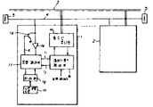
제 1 도 내지 제 3 도는 본 발명의 일실시예를 보인 도면으로서,1 to 3 is a view showing an embodiment of the present invention,
제 1 도는 회선 인터페이스부 불록도이고,1 is a block diagram of a circuit interface unit,
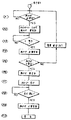
제 2 도는 기능모듈이 데이타 송신시의 플로우 챠트이며,2 is a flowchart in which a function module transmits data;
제 3 도는 제어선의 타임챠트이다.3 is a time chart of a control line.
제 4 도는 내지 제 7 도는 종래의 경합제어방식의 예를 보인 도면으로서,4 to 7 show examples of a conventional contention control method.
제 4 도는 이서네트의 회선 인터페이스부 불록도이고,4 is a block diagram of an Ethernet interface,
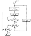
제 5 도는 이서네트의 경합제어 플로우챠트이며,5 is a contention control flowchart of Ethernet,
제 6 도는 CCITT I인터페이스 레이어 1블록도이고,6 is a block diagram of CCITT I
제 7 도는 I인터페이스 D채널 액세스 플로우챠트이다.7 is an I-interface D-channel access flowchart.
* 도면의 주요부분에 대한 부호의 설명* Explanation of symbols for main parts of the drawings
1, 2 : 기능모듈 3 : 전송매체1, 2: function module 3: transmission medium
4 : 제어선 1d : 구동수단인 트랜지스터4: control line 1d: transistor as driving means
1e : 식별수단인 레시버 1f : 경합제어부1e: Receiver as identification means 1f: Contention control unit
1g : 타이머 1h : 시간설정수단1g: Timer 1h: Time setting means
본 발명은 기능을 독립하여 정의할 수가 있는 기능모듈(Module)이 물리적으로 복수개 조립되어 하나의 시스템 또는 기기를 구성하는 경우에 하나의 전송매체를 공유하기 위하여 생기는 전송로상의 경합(경합)상태를 회피하는 것을 목적으로한 경합제어 시스템 및 경합제어방법에 관한 것이다. 복수개의 단말기기등의 기능모듈이 하나의 전송매체를 공유하기 위한 경합제어방식의 하나의 예로서 로컬 에어리어 네트워크(LAN) 가 있다.According to the present invention, when a plurality of functional modules capable of defining functions independently are physically assembled to form a system or a device, a contention (competition) state on a transmission path generated to share one transmission medium is described. A contention control system and a contention control method for the purpose of avoiding. A local area network (LAN) is an example of a contention control method for sharing a transmission medium by a function module such as a plurality of terminal devices.
LAN은 복수개의 기능모듈간의 전송에 전송매체가 공동사용되기 때문에 충돌을 발생시키지 않는 제어를 필요로 한다. 이 제어매체에 액세스하는 제어방식의 하나에CSMA/CD(Carrier Sense Mulitiple Access With Collision Detection)방식이 있다.The LAN requires a control that does not cause a collision because the transmission medium is jointly used for transmission between a plurality of functional modules. One control method for accessing the control medium is a carrier sense mulitiple access with collision detection (CSMA / CD) method.
제 4 도에 CSMS/CD방식을 사용한 대표적인 예인 이서네트( ether net)의 회선 인터페이스부 블록도를 표시한다. 제 4 도에서 11은 전송매체인 동축케이블, 12,15는 기능이 독립적으로 정의된 기능모듈(A), (N), 13은 전송매체와 전기.물리적으로 접속되는 물리층, 14는 송수신 데이타의 과오 제어를 주로하는 데이타 링크층이다. 물리층중의 13a는 전송매체에 송신데이타를 송출하기 위하여 구동회로 등으로부터 이루어지는 송신채널 액세스부, 13b는 송신데이타를 일정한 부호화 규책으로 송신채널 액세스부에 송출하기 위한 송신데이타 인코더, 13c는 전송매체의 신호를 수신하는 수신채널 액세스부, 13d는 수신데이타를 부호화 규칙에 기초하여 디코드하는 수신데이타 디코드부, 13e는 전송매체상의 경합상태를 검출하기 위한 충돌검출부, 13f는 수신채널 액세스부에 접속되어 전송매체에 데이타 송출의 유무를 식별하는 캐리어 검출부이다.4 is a block diagram of a circuit interface unit of an ethernet which is a representative example using the CSMS / CD method. In FIG. 4, 11 is a coaxial cable which is a transmission medium, 12 and 15 are functional modules (A), (N), and 13 are physical layers which are electrically and physically connected to the transmission medium, and 14 is a transmission / reception data. It is the data link layer which mainly deals with error control. 13a in the physical layer is a transmission channel access unit made from a driving circuit or the like for transmitting transmission data to a transmission medium, 13b is a transmission data encoder for transmitting transmission data to a transmission channel access unit with a predetermined encoding scheme, and 13c is a transmission data encoder. A receiving channel access unit for receiving a signal, 13d is a receiving data decoding unit for decoding received data based on encoding rules, 13e is a collision detection unit for detecting a race condition on a transmission medium, and 13f is connected to a receiving channel access unit for transmission. Carrier detection section for identifying the presence or absence of data transmission to the medium.
제 5 도는 이서네트의 경합제어 플로우챠트를 표시한 것이다. 다음에 동작을 설명한다. 데이타 송신을 하려고할 때 캐리어 검출부(13f)에서 리드(17)를 경유하여전송매체에 다른 기능모듈, 예를들면 15의 기능모듈(N)로부터 데이타의 송출이 없는 것을 확인한 후 14의 데이타 링크층으로부터 송신을 개시한다.5 shows an Ethernet contention control flowchart. Next, the operation will be described. When attempting to transmit data, the carrier detecting unit 13f confirms that data is not transmitted from another function module, for example, the function module N of 15, via the
데이타는 송신데이타 인코더(13b)→송신채널 액세스부(13a)를 경유하여 전송매체(11)에 송출된다. 충돌 검출부(13e)는 송신데이타와 전송매체→수신채널 액세스부를 경유하여 수신한 데이타의 비교를 수행하고 만약 타기능모듈에 의한 송신과 충돌한 경우에는 데이타의 불일치가 생기는 것으로서 충돌의 발생을 식별하고 리드(16)를 통하여 데이타 링크층에 이것을 통지한다. 이 통지에 의하여 데이타 링크층은 데이타의 송출을 정지하고 재송신의 준비를 행한다. 또 하나의 예로서 ISDN의 가입자선 인터페이스(I인터페이스)의 기본인터페이스의 경우를 기술한다. 기본 인터페이스의 레이어 1에 관하여는CCITT서비스 통합 디지털 망(ISDN)I시리즈 권고중에 권고(勸告)I. 430으로 규정되어 있다.The data is sent to the transmission medium 11 via the transmission data encoder 13b-> the transmission channel access section 13a. The collision detection unit 13e compares the received data via the transmission data and the transmission medium → receiving channel access unit.If the collision detection unit 13e conflicts with the transmission by another function module, it identifies the occurrence of the collision as the data inconsistency occurs. The read link 16 informs the data link layer. By this notification, the data link layer stops sending data and prepares for retransmission. As another example, the case of the basic interface of the subscriber line interface (I interface) of the ISDN will be described. For
이 규정내용의 레이어(레이어 1)중에 D채널 경합제어방식이 규정되어 복수의 기능모듈이 동시에 D 채널에 액세스한 경우의 충돌을 회피하기 위하여 에코채널을 사용한 경합 제어순서가 결정되어 있다. 제 6 도에 CCITT I 인터페이스 레이어 1 블록도의 일예를 표시한다. 제 6 도에 있어서 21은 ISDN망의 전송종단부(NT),21a는 에코작성부, 22는 기본 인터페이스의 하강 전송매체(2선의 금속선), 23은 상승전송매체, 24, 25는 이 전송매체를 공유하는 기능모듈(TE), 26은 TE에서의 송신데이타 플레임, 26a는 송신 D채널 데이타, 27은 NT에서의 수신데이타, 27a는 내부의 에코작성부(21aF)에 의한 26a의 D채널데이타의 반려신호(에코신호)이다.In the layer (layer 1) of this specification, the D channel contention control method is specified, and a contention control procedure using an echo channel is determined to avoid collisions when a plurality of functional modules simultaneously access the D channel. 6 shows an example of a CCITT I
기능모듈속의 24a는 데이타의 송신부, 24b는 데이타의 수신부, 24c는 송신데이타와 에코데이타와의 비교부, 24d는 D채널 감시부이다. 제 7 도에 I인터페이스 D채널 액세스 플로우챠트를 개략적으로 표시한다. 기능모듈이 D채널을 사용하고자 할 때 동공상태의 확인등의 일정한 순서를 실행한 후 송신데이타 플레임중의 D비트 송신타이밍에 데이타를 송신부(24a)에서 송신하면 동시에 D비트를 비교부(24c)에 기억한다. NT는 항상 상승방향의D채널의 내용을 하강방향으로 설치한 에코채널(E)에 비트마다로 되돌려 보낸다. 기능모듈에서는 에코채널을 통하여 에코비트와 자기의 송출한 D채널 비트와를 비교부(24c)에서 비교한다.In the functional module, 24a is a data transmission unit, 24b is a data reception unit, 24c is a comparison unit between transmission data and echo data, and 24d is a D-channel monitoring unit. 7 schematically shows an I-interface D-channel access flowchart. When the function module intends to use the D channel, it executes a certain procedure such as confirmation of the pupil state, and then transmits data to the D bit transmission timing during the transmission data frame from the transmitter 24a. Remember to. The NT always sends the contents of the D channel in the upward direction bit by bit to the echo channel E provided in the downward direction. In the functional module, the
이것이 다른 경우에는 이것을 먼저 검출한 기능모듈이 비교부 출력의 불일치 정보에서 경합을 인식하고 플레임 송신을 중단하고 이것이 동일한 경우에는 플레임의 송신을 수행하는 것에 의하여 경합한 경우라도 하나의 기능모듈로부터의 플레임만이 이겨서 남는 것이 된다. 하나의 전송매체를 공유하는 복수개의 독립된 기능모듈이 존재하는 경우의 경합제어 방식예로서 이상 두가지예를 기재한다.If this is different, the function module that detects this first detects contention in the discrepancy information of the comparator output and stops transmitting the frame. If this is the same, the frame from one function module is contended by performing the transmission of the frame. Only one wins and remains. The above two examples are described as an example of a contention control method in the case where there are a plurality of independent functional modules sharing one transmission medium.
그러나 상기 구성의 방식에서는 설명에서 명백한 바와 같이However, in the manner of the above configuration, as is apparent from the description
(a) 전송매체의 동공을 검출하기 위하여 복잡한 감시용 하드웨어가 필요하다.(a) Complex monitoring hardware is required to detect pupils in the transmission medium.
(b) 송신, 수신데이타의 비교를 행하는 하드웨어가 필요하다.(b) Hardware for comparing the transmission and reception data is required.
(c) 데이타의 송출은 개시하지 않으면 경합을 검출할 수 없으므로 데이타 재송순서가 필요하게 된다.(c) If data transmission is not started, contention cannot be detected. Therefore, the data resending procedure is necessary.
는 등의 문제점이 있어 비교적 저가격으로 단거리의 전송 매체를 공유하는 기능모듈에 사용하기 위하여는 가격이 높아지는 결점이 있었다.There is a problem in that the price is high for use in the functional module sharing a short-range transmission medium at a relatively low price.
본 발명의 목적은 상기 종래 기술이 가지고 있던 문제점을 제거하여 낮은 가격으로 간단한 경합제어 시스템 및 경합 제어방법을 제공하는 것이다. 상기 목적달성을 위한 본 발명의 일특징에 따라 복수의 독립적 기능모듈에 의해 공유되는 하나의 전송매체를 위한 경합제어시스템은 상기 전송매체와 분리된 제어선과, 데이타전송전에 상기 제어선을 감시하고, 소정의 경합시간 폭동안 상기 제어선을 활성화하며, 이때 상기 제어선을 다시 감시하여 상기 제어선이 활성화상태이면 대기상태로 되돌아가고 또는 상기 제어선을 활성화하고, 데이타 전송을 개시하며, 상기 데이타전송중에 활성화상태에서 상기 제어선을 유지하기 위한 상기 각 기능모듈에 있는 제어수단을 포함한다. 상기 제어수단은 상기 제어선에 결합되어 있되, 상기 제어선을 활성화하는 구동수단과, 상기 제어선에 결합되어 있되, 상기 제어선이 활성화 또는 비활성화 상태인지를 식별하기 위한 식별수단과, 상기 경합시간폭의 길이를 결정하기 위한 타이밍수단과, 상기 구동수단, 타이밍수단 및 식별수단에 결합되어 있되, 상기 제어선이 비활성화 상태인지를 표시하는 상기 식별수단으로부터 제공되는 신호를 수신하고, 상기 제어선이 비활성화상태인 경우 상기 구동수단을 온상태로 구동하며, 상기 타이밍수단에 의해 결정된 상기 경합시간폭의 종료에서 상기 구동수단을 오프상태로 구동하며, 아울러 상기 데이타전송의 개시 및 종료시에 상기 구동수단을 온상태 및 오프상태로 구동하는 제어수단을 포함한다.An object of the present invention is to provide a simple contention control system and a contention control method at a low cost by eliminating the problems of the prior art. According to one aspect of the present invention for achieving the above object, a contention control system for one transmission medium shared by a plurality of independent functional modules monitors the control line separated from the transmission medium and the control line before data transmission. The control line is activated for a predetermined contention time width, wherein the control line is again monitored to return to the standby state if the control line is activated or to activate the control line, start data transmission, and transmit the data. Control means in each of the functional modules for holding the control line in an activated state. The control means is coupled to the control line, drive means for activating the control line, identification means for identifying whether the control line is activated or deactivated, coupled to the control line, and the contention time A timing means for determining the length of the width, and coupled to the driving means, the timing means and the identification means, the signal being provided from the identification means indicating whether the control line is in an inactive state, the control line being In the inactive state, the driving means is driven in an on state, and the driving means is driven off at the end of the contention time duration determined by the timing means, and at the start and end of the data transfer, the driving means is driven. Control means for driving in an on state and an off state.
상기 타이밍수단은 상기 경합시간폭의 길이를 측정하는 타이머와 상기 타이머를 프리세트하기 위한 시간 설정 수단을 포함한다.The timing means includes a timer for measuring the length of the contention time width and time setting means for presetting the timer.
상기 각 기능모듈은 서로 상이한 길이의 경합시간폭을 적용한 것이다. 우선순위의 기능모듈은 더 긴길이의 경합시간폭을 적용한 것이다.Each functional module applies contention time widths of different lengths. Priority function modules have a longer contention duration.
본 발명의 다른 특징에 의하면, 전송매체를 통하여 데이타를 적어도 송신하기 위해 결합된 복수의 독립적 기능모듈에 의해 공유되는 전송메체내에서, 기능모듈에 접속된 제어선과 연계되고, 각 기능모듈이 상기 제어선을 활성화하고 아울러 상기 제어선의 상태를 검사하는 전송메체의 경합 제어방법은 상기 제어선이 비활성인 경우를 식별하기 위하여 상기 제어선의 상태를 거사하는 단계와, 상기 제어선이 비활성으로 식별된 경우 상기 제어선을 소정의 경합시간폭 동안 활성화하는 단계와, 상기 제어선이 비활성인 경우를 식별하기 위하여 상기 제어선의 상태를 검사하는 단계와, 상기 제어선을 재차 활성화하는 단계와, 데이타전송을 개시하고 아울러 데이타전송중에 상기 제어선을 활성상태로 유지하는 단계를 포함한다.According to another feature of the invention, in a transmission medium shared by a plurality of independent function modules coupled for at least data transmission via a transmission medium, associated with a control line connected to a function module, each function module is controlled by the control module. The contention control method of a transmission medium for activating a line and checking a state of the control line may include: deciding a state of the control line to identify a case in which the control line is inactive, and when the control line is identified as inactive, Activating the control line for a predetermined contention time period, inspecting the state of the control line to identify when the control line is inactive, activating the control line again, and initiating data transmission; And maintaining the control line active during data transmission.
상기 기능모듈은 상이한 길이를 갖는 경합시간폭을 적용한 것이다.The functional module applies contention time widths having different lengths.
상기 더 빠른 우선도를 갖는 기능모듈은 더 긴 길이를 갖는 경합시간폭을 적용한다. 본 발명의 또다른 특징에 의한 하나의 전송매체를 공유하는 경합제어 시스템은, 상기 전송매체와 분리된 제어선과, 각 기능모듈이 상기 전송매체에 결합된 송수신유니트와, 상기 송수신유니트에 결합된 데이타링크 제어부와 상기 제어선에 결합되어 있되, 상기 제어선이 활성화 또는 비활성화상태의 여부를 표시하는 신호를 발생하는 레시버와, 상기 제어선에 결합되어 있되, 상기 제어선이 비활성화 상태인 경우 상기 제어선의 활성화를 위한 구동수단과, 타이밍수단 및 상기 데이타 링크제어부와 레시버와 구동수단과 타이밍수단에 결합되어 있되, 상기레시버에서 상기 제어선이 비활성상태인 것을 표시한 경우 상기 구동수단 및 타이밍수단을 온시켜서 상기제어선을 활성화하고, 상기 타이밍수단에 의해 설정된 소정의 경합시간폭의 종료시에 상기 구동수단을 오프시켜서 상기 제어선의 활성화상태를 해제하며, 상기 전송매체상에서 상기 송수신유니트에 의해 데이타전송을 개시하기 위하여 상기 데이타 링크제어부를 동시에 지령하는 동안 상기 제어선을 다시 활성화하기 위해 상기 제어선이 비활성화상태인 것을 상기 레시버에서 표시한 경우 상기 구동수단을 다시 온시키며, 상기 데이타 전송종료시에 상기 구동수단을 오프시켜서 상기 제어선의 활성화상태를 해제하고 아울러 상기 전송매체를 다른 기능모듈에서 이용할수 있게한 복수의 기능모듈을 포함한다. 상기 타이밍수단은 상기 경합시간폭의 길이를 측정하는 타이머와 상기 타이머를 프리세트시키기 위한 시간설정수단을 포함하다. 상기 각 기능모듈은 상이한 길이를 갖는 경합시간폭을 적용한다. 상기 구동수단은 상기 레시버와 제어선사이에 접속된 제 1전극과, 상기 경합제어부에 접속된 제 2전극을 갖는 트랜지스터로 구성한다.The faster priority functional module applies a contention time width with a longer length. According to another aspect of the present invention, a contention control system sharing one transmission medium includes a control line separated from the transmission medium, a transmission / reception unit in which each function module is coupled to the transmission medium, and data coupled to the transmission / reception unit. A receiver coupled to a link control unit and the control line, the receiver generating a signal indicating whether the control line is in an activated or deactivated state; and coupled to the control line, wherein the control line is in an inactive state. A driving means for activating a line, a timing means, the data link control unit, a receiver, a driving means, and a timing means, wherein the driving means and timing means when the receiver indicates that the control line is inactive. Is turned on to activate the control line, and at the end of the predetermined contention time period set by the timing means, The control line is deactivated by turning off the driving means to reactivate the control line while simultaneously instructing the data link control unit to initiate data transmission by the transmission / reception unit on the transmission medium. When the receiver indicates that it is in an inactive state, the driving means is turned on again, and the driving means is turned off at the end of the data transmission to release the control line and to make the transmission medium available to another function module. It includes a plurality of functional modules. The timing means includes a timer for measuring the length of the contention time width and time setting means for presetting the timer. Each functional module applies a contention time width having a different length. The drive means comprises a transistor having a first electrode connected between the receiver and a control line and a second electrode connected to the contention control section.
이하 본 발명의 실시예를 상세히 설명한다.Hereinafter, embodiments of the present invention will be described in detail.
제 1 도는 본 발명에 의한 회선 인터페이스부의 블록도로서 1 및 2는 데이타의 송.수신을 행하는 기능을 가진 기농모듈, 3은 복수의 기증모듈에 공유화된 전송매체, 4는 기능모듈간에서 공통으로 구동.감시를 행하는 제어선이며 필요에 응하여 종단저항(5)을 부가한다. 기능모듈중의 1a는 전송매체를 접속되어 있는 데이타의 송수신 유니트, 1b는 데이타의 과오제어등을 행하는 데이타 링크 제어부, 1d는 제어선을 활성화시키기 위하여 이 제어선에 와이어드 오어(wired-OR)접속된 구동수단인 트랜지스터, 1e는 제어선의 활성. 비활성의 식별수단인 레시버, 1f는 제어선의 구동.감시를 제어하며 경합제어의 순서를 실행하기 위한 경합제어부, 1g는 타이머, 1h는 시간설정수단이다.1 is a block diagram of a circuit interface unit according to the present invention, 1 and 2 is a farming module having a function of transmitting and receiving data, 3 is a transmission medium shared by a plurality of donor modules, and 4 is common among functional modules. It is a control line for driving and monitoring. A terminating
상기 타이머(1g)와 시간설정수단(1h)으로 타이밍수단을 구성한다.The timing means is constituted by the timer 1g and the time setting means 1h.
제 2 도는 본 발명에 의한 송신시의 플로우, 제 3 도는 본 발명 제어선의 타임챠트이다.2 is a flowchart of transmission according to the present invention, and FIG. 3 is a time chart of the control line of the present invention.
다음에 동작을 설명한다.Next, the operation will be described.
송신데이타의 발생한 기능모듈은 데이타 링크베어부(1b)로부터 정보선(1j)을 통하여 경합제어부(1f)에 송신요구를 낸다.The generated function module of the transmission data issues a transmission request from the data link bearing unit 1b to the contention control unit 1f via the information line 1j.
이 요구를 받은 경합제어부는 전송매체(3)의 동공상태를 나타내는 제어선(4)의 극성 즉 활성이나 비활성이냐를 레시버(1e)를 통하여 읽어 넣는다. 제어선이 비활성이면 타이머(1g)를 스타트하고 시간설정수단(1h)에 의하여 미리 정하여진 시간(t)만큼 트랜지스터(1d)를 리드(1c)를 경유하여 구동하고 제어선(4)을 활성화한다.This contention control section reads through the receiver 1e the polarity of the control line 4 indicating the pupil state of the
시간(t)의 경과를 타이머(1g)에서 통지하면 경합제어부(1f)는 한번 제어선(4)을 비활성으로 하기 위하여 트랜지스터(1d)의 구동을 일시 정지한다.When the timer 1g notifies the elapse of the time t, the contention control unit 1f temporarily stops driving the transistor 1d to inactivate the control line 4 once.
이때 만약 다른 모듈 예를들면 2가 전송의 의지가 잇으면 같은 순서로서 제어선(4)을 활성화하고 있으므로 모듈(1)이 제어선을 비활성상태로 하여도 레시버(1e)의 출력은 활성상태를 계속할 것이다.At this time, if another module, for example, 2 is willing to transmit, the control line 4 is activated in the same order, so that the output of the receiver 1e is active even if the
이것에 의하여 기능모듈은 경합의 발생을 알 수가 있어서 다기금 대기상태에서부터 개시한다. 기능모듈(1)이 비활성상태로한때 제어선의 비활성상태가 레시버(1e)를 통하여 얻을 수 있다면 모듈은 경합상태 없는 것을 알고 제어선(4)을 제차 활성화하여 전송매체(3)가 사용중인 것을 통지함과 동시에 전송매체(3)를 통하여 데이타송신을 개시한다. 데이타의 송신이 종료하면 제어선(4)을 비활성상태로 복귀시키는 것에 의하여 송신이 종료한다. 타이머의 시간치(t)는 기능모듈마다 다른 값으로 설정하는 것이 바람직스러우며 시간치(t)가 긴 기능모듈일수록 우선도가 높아진다. 본 발명의 전송매체(3)는 2심(芯), 4심의 평행케이블, 동축케이블, 광케이블등 그 종류별, 그 수에 하등의 제한되는 것은 아니다.As a result, the function module can recognize the occurrence of contention and starts from the multi-fund standby state. If the inactive state of the control line can be obtained through the receiver 1e when the
본 발명의 제어선에 관하여도 드라이브 능력이 충분하면 기능모듈간의 외부버스에 사용할 수가 있다. 또,제어선의 활성화 시간폭을 결정하는 시간설정수단으로서 실시예에서는 타이머와 시간설정수단의 구성에서 설명하였으나 이것에 한정되는 것은 아니며 하드회로에서 실현하여도 마이크로컴퓨터등과 메모리를 사용하여 소프트적으로 시간 설정수단을 구성하여도 적용가능한 것은 물론이다. 이상 상세히 설명한 것과같이 본 발명에 의하면 제어선의 활성, 비활성을 이용하여 하나의 전송매체를 공유하는 경합제어방식이 극히 간단하게 실현된다.Also in the control line of the present invention, if the drive capability is sufficient, it can be used for an external bus between functional modules. The time setting means for determining the activation time width of the control line has been described in the configuration of the timer and the time setting means in the embodiment. However, the present invention is not limited to this. It goes without saying that it is applicable to the configuration of the time setting means. As described in detail above, according to the present invention, a contention control scheme in which one transmission medium is shared using active and inactive control lines is extremely simple.
이것 때문에 기능모듈의 본래의 제어에 사용되는 마이크로 컴퓨터등의 처리능력의 일부를 충당하는 것만으로 경합제어를 용이하게 실시할 수가 있다.For this reason, contention control can be easily performed only by covering a part of the processing capability of the microcomputer or the like used for the original control of the function module.
이것에 의하여 예를들어 기기내의 독립된 기능모듈이 하나의 공통된 기능모듈에 접속되어 독립하고 있으므로 경합상태가 발생하는 것과 같은 케이스의 내부 인터페이스가 낮은 가격으로 시현시킬 수가 있게 된다.This allows, for example, the independent functional modules in the device to be connected to one common functional module and are independent, thereby making the internal interface of the case such as a race condition occur at a low price.
Claims (13)
Applications Claiming Priority (3)
| Application Number | Priority Date | Filing Date | Title |
|---|---|---|---|
| JP62161358A JPH0646733B2 (en) | 1987-06-30 | 1987-06-30 | Contention control method sharing one transmission medium |
| JP?62-161358 | 1987-06-30 | ||
| JP87-161358 | 1987-06-30 |
Publications (2)
| Publication Number | Publication Date |
|---|---|
| KR890001324A KR890001324A (en) | 1989-03-20 |
| KR920004146B1 true KR920004146B1 (en) | 1992-05-25 |
Family
ID=15733565
Family Applications (1)
| Application Number | Title | Priority Date | Filing Date |
|---|---|---|---|
| KR1019880007785A KR920004146B1 (en) | 1987-06-30 | 1988-06-27 | Contention control system |
Country Status (8)
| Country | Link |
|---|---|
| US (1) | US5065153A (en) |
| JP (1) | JPH0646733B2 (en) |
| KR (1) | KR920004146B1 (en) |
| CA (1) | CA1288836C (en) |
| GB (1) | GB2206468B (en) |
| HK (1) | HK34392A (en) |
| IN (1) | IN169053B (en) |
| SG (1) | SG8492G (en) |
Families Citing this family (14)
| Publication number | Priority date | Publication date | Assignee | Title |
|---|---|---|---|---|
| US5167022A (en) * | 1988-10-25 | 1992-11-24 | Hewlett-Packard Company | Multiprocessor bus locking system with a winning processor broadcasting an ownership signal causing all processors to halt their requests |
| US5040175A (en) * | 1990-04-11 | 1991-08-13 | Ncr Corporation | Wireless information transmission system |
| US5661467A (en) * | 1991-02-18 | 1997-08-26 | Nec Corporation | Method and system for transferring supervisory right requirement in submarine cable communication network system |
| FR2678085B1 (en) * | 1991-06-24 | 1995-04-14 | Sgs Thomson Microelectronics | METHOD FOR MANAGING TRANSMISSION OF INFORMATION ON AN ELECTRICAL DISTRIBUTION CIRCUIT, DEVICE FOR ITS IMPLEMENTATION AND APPLICATION OF THE PROCESS TO COMMUNICATIONS IN A HOME AUTOMATION SYSTEM. |
| US5335226A (en) * | 1992-06-18 | 1994-08-02 | Digital Equipment Corporation | Communications system with reliable collision detection method and apparatus |
| US5479613A (en) * | 1992-08-05 | 1995-12-26 | International Business Machines Corporation | Real-time ring bandwidth utilization calculator, calculating bandwidth utilization based on occurrences of first and second predetermined bit patterns |
| US5311512A (en) * | 1992-12-14 | 1994-05-10 | At&T Bell Laboratories | Multiple-master digital communication technique utilizing a dedicated contention bus |
| DE4407795A1 (en) * | 1994-03-09 | 1995-09-14 | Sel Alcatel Ag | Method and circuit arrangement for coordinating the access of several message sources to a bus |
| WO1995030263A1 (en) * | 1994-05-03 | 1995-11-09 | Electro-Wire Products, Inc. | Power distribution module |
| US5729547A (en) * | 1996-02-07 | 1998-03-17 | Dutec, Inc. | Automatic driver/receiver control for half-duplex serial networks |
| US6256319B1 (en) * | 1997-02-28 | 2001-07-03 | Avaya Technology Corp. | “Plug and play” telephone system |
| FR2778994B1 (en) | 1998-05-25 | 2001-08-31 | Suisse Electronique Microtech | COMMUNICATION DEVICE BETWEEN A NEURONAL NETWORK AND A USER SYSTEM THROUGH A BUS |
| CN1937615B (en) * | 2005-09-20 | 2012-01-25 | 株式会社Ntt都科摩 | Media accessing control method and apparatus in wireless distribution type network |
| CN101667951A (en) * | 2008-09-02 | 2010-03-10 | 鸿富锦精密工业(深圳)有限公司 | Network device and data transmission method thereof |
Family Cites Families (9)
| Publication number | Priority date | Publication date | Assignee | Title |
|---|---|---|---|---|
| GB1480208A (en) * | 1974-07-03 | 1977-07-20 | Data Loop Ltd | Digital computers |
| JPS5824061B2 (en) * | 1979-03-05 | 1983-05-19 | 横河電機株式会社 | Data communication control method |
| US4292623A (en) * | 1979-06-29 | 1981-09-29 | International Business Machines Corporation | Port logic for a communication bus system |
| GB2101457B (en) * | 1981-07-08 | 1985-04-17 | Int Computers Ltd | Data communication system |
| US4556939A (en) * | 1983-04-29 | 1985-12-03 | Honeywell Inc. | Apparatus for providing conflict-free highway access |
| US4652873A (en) * | 1984-01-18 | 1987-03-24 | The Babcock & Wilcox Company | Access control for a plurality of modules to a common bus |
| US4638311A (en) * | 1984-11-13 | 1987-01-20 | Itt Corporation | Apparatus for providing masterless collision detection |
| US4807223A (en) * | 1987-10-08 | 1989-02-21 | Critikon, Inc. | Communications protocol for distributed station network |
| US4755990A (en) * | 1987-10-08 | 1988-07-05 | Karl Suss America, Inc. | Collision avoidance in a multinode data communication network |
-
1987
- 1987-06-30 JP JP62161358A patent/JPH0646733B2/en not_active Expired - Fee Related
-
1988
- 1988-06-22 GB GB8814875A patent/GB2206468B/en not_active Expired - Fee Related
- 1988-06-24 US US07/211,555 patent/US5065153A/en not_active Expired - Lifetime
- 1988-06-27 CA CA000570504A patent/CA1288836C/en not_active Expired - Fee Related
- 1988-06-27 KR KR1019880007785A patent/KR920004146B1/en not_active IP Right Cessation
- 1988-07-01 IN IN540/CAL/88A patent/IN169053B/en unknown
-
1992
- 1992-01-30 SG SG84/92A patent/SG8492G/en unknown
- 1992-05-14 HK HK343/92A patent/HK34392A/en not_active IP Right Cessation
Also Published As
| Publication number | Publication date |
|---|---|
| HK34392A (en) | 1992-05-22 |
| JPH0646733B2 (en) | 1994-06-15 |
| SG8492G (en) | 1992-03-20 |
| JPS647746A (en) | 1989-01-11 |
| CA1288836C (en) | 1991-09-10 |
| GB2206468B (en) | 1991-09-11 |
| IN169053B (en) | 1991-08-24 |
| KR890001324A (en) | 1989-03-20 |
| US5065153A (en) | 1991-11-12 |
| GB8814875D0 (en) | 1988-07-27 |
| GB2206468A (en) | 1989-01-05 |
Similar Documents
| Publication | Publication Date | Title |
|---|---|---|
| KR920004146B1 (en) | Contention control system | |
| US4760571A (en) | Ring network for communication between one chip processors | |
| EP1022878B1 (en) | Data transmission system | |
| CN101690009B (en) | Communication system and communication method | |
| EP0094180A2 (en) | Dual-count, round-robin distributed arbitration technique for serial buses | |
| KR890001309A (en) | Information packet transmission method and transceiver | |
| JPH09162903A (en) | Radio transmission equipment | |
| US4573154A (en) | Data communication system with error detection/correction | |
| US5289466A (en) | Multiplex transmission method | |
| KR940006362A (en) | Dual communication control | |
| US5982781A (en) | Process for information transmission in a bus system having several participants | |
| US5602849A (en) | Communication bus system and station for use in such system | |
| JPH07154400A (en) | Digital communication system and data transmission method | |
| JPS59168736A (en) | Multi-drop transmission system | |
| GB2101457A (en) | Data communication system | |
| JP2937871B2 (en) | Polling monitoring method | |
| JP3252556B2 (en) | Communication device | |
| JPH06311165A (en) | Transmission equipment | |
| JP2910264B2 (en) | Abnormal reception response detection device | |
| JP3047626B2 (en) | Communication control device | |
| JP3355988B2 (en) | Data transmission equipment | |
| JPS60204144A (en) | Fault detecting system in bus type communication system | |
| JPH01130646A (en) | Data transfer system | |
| JPH0120819B2 (en) | ||
| JPH02209037A (en) | System and equipment for transmission control in data transmission network |
Legal Events
| Date | Code | Title | Description |
|---|---|---|---|
| A201 | Request for examination | ||
| E902 | Notification of reason for refusal | ||
| G160 | Decision to publish patent application | ||
| E701 | Decision to grant or registration of patent right | ||
| GRNT | Written decision to grant | ||
| FPAY | Annual fee payment |
Payment date: 19980519 Year of fee payment: 7 |
|
| LAPS | Lapse due to unpaid annual fee |