KR20180105747A - Roadway powered electric vehicle system - Google Patents
Roadway powered electric vehicle system Download PDFInfo
- Publication number
- KR20180105747A KR20180105747A KR1020187026916A KR20187026916A KR20180105747A KR 20180105747 A KR20180105747 A KR 20180105747A KR 1020187026916 A KR1020187026916 A KR 1020187026916A KR 20187026916 A KR20187026916 A KR 20187026916A KR 20180105747 A KR20180105747 A KR 20180105747A
- Authority
- KR
- South Korea
- Prior art keywords
- power
- vehicle
- road
- module
- coil
- Prior art date
Links
- 230000005540 biological transmission Effects 0.000 claims description 104
- 230000001939 inductive effect Effects 0.000 claims description 55
- 238000000034 method Methods 0.000 claims description 20
- 239000004020 conductor Substances 0.000 claims description 9
- 238000013459 approach Methods 0.000 claims description 6
- 230000004907 flux Effects 0.000 description 108
- 229910000859 α-Fe Inorganic materials 0.000 description 90
- 238000004804 winding Methods 0.000 description 43
- 101710170564 Bradykinin-potentiating peptide Proteins 0.000 description 32
- 101710128871 Bradykinin-potentiating peptide Phypo Xa Proteins 0.000 description 32
- 239000003990 capacitor Substances 0.000 description 32
- 238000010168 coupling process Methods 0.000 description 31
- 238000005859 coupling reaction Methods 0.000 description 31
- 230000008878 coupling Effects 0.000 description 29
- 238000010586 diagram Methods 0.000 description 22
- 238000012546 transfer Methods 0.000 description 15
- 229910052782 aluminium Inorganic materials 0.000 description 11
- XAGFODPZIPBFFR-UHFFFAOYSA-N aluminium Chemical compound [Al] XAGFODPZIPBFFR-UHFFFAOYSA-N 0.000 description 11
- 230000008859 change Effects 0.000 description 11
- 238000013461 design Methods 0.000 description 11
- 230000001965 increasing effect Effects 0.000 description 11
- 238000004088 simulation Methods 0.000 description 11
- 230000033001 locomotion Effects 0.000 description 10
- 230000008901 benefit Effects 0.000 description 8
- 238000005259 measurement Methods 0.000 description 8
- 238000004891 communication Methods 0.000 description 7
- 239000000463 material Substances 0.000 description 7
- 229910000831 Steel Inorganic materials 0.000 description 6
- 238000010304 firing Methods 0.000 description 6
- 230000006698 induction Effects 0.000 description 6
- 230000002829 reductive effect Effects 0.000 description 6
- 239000010959 steel Substances 0.000 description 6
- 125000006850 spacer group Chemical group 0.000 description 5
- 238000010276 construction Methods 0.000 description 4
- 238000006073 displacement reaction Methods 0.000 description 4
- 230000001360 synchronised effect Effects 0.000 description 4
- 230000032683 aging Effects 0.000 description 3
- 230000001276 controlling effect Effects 0.000 description 3
- 230000000694 effects Effects 0.000 description 3
- 238000005516 engineering process Methods 0.000 description 3
- 230000014509 gene expression Effects 0.000 description 3
- 238000002955 isolation Methods 0.000 description 3
- 230000003068 static effect Effects 0.000 description 3
- RYGMFSIKBFXOCR-UHFFFAOYSA-N Copper Chemical compound [Cu] RYGMFSIKBFXOCR-UHFFFAOYSA-N 0.000 description 2
- 238000004458 analytical method Methods 0.000 description 2
- 230000033228 biological regulation Effects 0.000 description 2
- 230000000903 blocking effect Effects 0.000 description 2
- 238000006243 chemical reaction Methods 0.000 description 2
- 238000005094 computer simulation Methods 0.000 description 2
- 238000012937 correction Methods 0.000 description 2
- 230000007423 decrease Effects 0.000 description 2
- 230000003111 delayed effect Effects 0.000 description 2
- 238000004146 energy storage Methods 0.000 description 2
- 238000011156 evaluation Methods 0.000 description 2
- 238000010438 heat treatment Methods 0.000 description 2
- 230000000670 limiting effect Effects 0.000 description 2
- 238000007726 management method Methods 0.000 description 2
- 230000007246 mechanism Effects 0.000 description 2
- 229910052751 metal Inorganic materials 0.000 description 2
- 239000002184 metal Substances 0.000 description 2
- 230000035699 permeability Effects 0.000 description 2
- 230000004044 response Effects 0.000 description 2
- 230000035945 sensitivity Effects 0.000 description 2
- 238000000926 separation method Methods 0.000 description 2
- 230000035882 stress Effects 0.000 description 2
- 230000009466 transformation Effects 0.000 description 2
- 230000001052 transient effect Effects 0.000 description 2
- 229920000049 Carbon (fiber) Polymers 0.000 description 1
- 230000002159 abnormal effect Effects 0.000 description 1
- 230000002745 absorbent Effects 0.000 description 1
- 239000002250 absorbent Substances 0.000 description 1
- 238000009825 accumulation Methods 0.000 description 1
- 230000009286 beneficial effect Effects 0.000 description 1
- 239000004917 carbon fiber Substances 0.000 description 1
- 230000015556 catabolic process Effects 0.000 description 1
- 229910010293 ceramic material Inorganic materials 0.000 description 1
- 230000000295 complement effect Effects 0.000 description 1
- 229910052802 copper Inorganic materials 0.000 description 1
- 239000010949 copper Substances 0.000 description 1
- 230000001186 cumulative effect Effects 0.000 description 1
- 230000007547 defect Effects 0.000 description 1
- 238000006731 degradation reaction Methods 0.000 description 1
- 238000009826 distribution Methods 0.000 description 1
- 230000005611 electricity Effects 0.000 description 1
- 230000005284 excitation Effects 0.000 description 1
- 230000006872 improvement Effects 0.000 description 1
- 238000004519 manufacturing process Methods 0.000 description 1
- 239000007769 metal material Substances 0.000 description 1
- VNWKTOKETHGBQD-UHFFFAOYSA-N methane Chemical compound C VNWKTOKETHGBQD-UHFFFAOYSA-N 0.000 description 1
- PEGJUOKGCQTYPH-UHFFFAOYSA-N n-(1,3-dimethylpyrazolo[3,4-b]quinolin-4-yl)-n',n'-dimethylpropane-1,3-diamine Chemical compound C1=CC=C2C(NCCCN(C)C)=C(C(C)=NN3C)C3=NC2=C1 PEGJUOKGCQTYPH-UHFFFAOYSA-N 0.000 description 1
- 238000005457 optimization Methods 0.000 description 1
- 239000003973 paint Substances 0.000 description 1
- 235000012771 pancakes Nutrition 0.000 description 1
- 230000036961 partial effect Effects 0.000 description 1
- 238000005191 phase separation Methods 0.000 description 1
- 230000010363 phase shift Effects 0.000 description 1
- 230000008569 process Effects 0.000 description 1
- 230000001681 protective effect Effects 0.000 description 1
- 230000001105 regulatory effect Effects 0.000 description 1
- 230000003014 reinforcing effect Effects 0.000 description 1
- 238000007493 shaping process Methods 0.000 description 1
- 239000000725 suspension Substances 0.000 description 1
- 230000029305 taxis Effects 0.000 description 1
- 230000002123 temporal effect Effects 0.000 description 1
- 238000005382 thermal cycling Methods 0.000 description 1
- 239000002699 waste material Substances 0.000 description 1
- 239000002023 wood Substances 0.000 description 1
Images


Classifications
-
- B60L11/182—
-
- H—ELECTRICITY
- H01—ELECTRIC ELEMENTS
- H01F—MAGNETS; INDUCTANCES; TRANSFORMERS; SELECTION OF MATERIALS FOR THEIR MAGNETIC PROPERTIES
- H01F38/00—Adaptations of transformers or inductances for specific applications or functions
- H01F38/14—Inductive couplings
-
- B60L11/1816—
-
- B60L11/1829—
-
- B—PERFORMING OPERATIONS; TRANSPORTING
- B60—VEHICLES IN GENERAL
- B60L—PROPULSION OF ELECTRICALLY-PROPELLED VEHICLES; SUPPLYING ELECTRIC POWER FOR AUXILIARY EQUIPMENT OF ELECTRICALLY-PROPELLED VEHICLES; ELECTRODYNAMIC BRAKE SYSTEMS FOR VEHICLES IN GENERAL; MAGNETIC SUSPENSION OR LEVITATION FOR VEHICLES; MONITORING OPERATING VARIABLES OF ELECTRICALLY-PROPELLED VEHICLES; ELECTRIC SAFETY DEVICES FOR ELECTRICALLY-PROPELLED VEHICLES
- B60L5/00—Current collectors for power supply lines of electrically-propelled vehicles
- B60L5/005—Current collectors for power supply lines of electrically-propelled vehicles without mechanical contact between the collector and the power supply line
-
- B—PERFORMING OPERATIONS; TRANSPORTING
- B60—VEHICLES IN GENERAL
- B60L—PROPULSION OF ELECTRICALLY-PROPELLED VEHICLES; SUPPLYING ELECTRIC POWER FOR AUXILIARY EQUIPMENT OF ELECTRICALLY-PROPELLED VEHICLES; ELECTRODYNAMIC BRAKE SYSTEMS FOR VEHICLES IN GENERAL; MAGNETIC SUSPENSION OR LEVITATION FOR VEHICLES; MONITORING OPERATING VARIABLES OF ELECTRICALLY-PROPELLED VEHICLES; ELECTRIC SAFETY DEVICES FOR ELECTRICALLY-PROPELLED VEHICLES
- B60L53/00—Methods of charging batteries, specially adapted for electric vehicles; Charging stations or on-board charging equipment therefor; Exchange of energy storage elements in electric vehicles
- B60L53/10—Methods of charging batteries, specially adapted for electric vehicles; Charging stations or on-board charging equipment therefor; Exchange of energy storage elements in electric vehicles characterised by the energy transfer between the charging station and the vehicle
- B60L53/12—Inductive energy transfer
- B60L53/122—Circuits or methods for driving the primary coil, e.g. supplying electric power to the coil
-
- B—PERFORMING OPERATIONS; TRANSPORTING
- B60—VEHICLES IN GENERAL
- B60L—PROPULSION OF ELECTRICALLY-PROPELLED VEHICLES; SUPPLYING ELECTRIC POWER FOR AUXILIARY EQUIPMENT OF ELECTRICALLY-PROPELLED VEHICLES; ELECTRODYNAMIC BRAKE SYSTEMS FOR VEHICLES IN GENERAL; MAGNETIC SUSPENSION OR LEVITATION FOR VEHICLES; MONITORING OPERATING VARIABLES OF ELECTRICALLY-PROPELLED VEHICLES; ELECTRIC SAFETY DEVICES FOR ELECTRICALLY-PROPELLED VEHICLES
- B60L53/00—Methods of charging batteries, specially adapted for electric vehicles; Charging stations or on-board charging equipment therefor; Exchange of energy storage elements in electric vehicles
- B60L53/10—Methods of charging batteries, specially adapted for electric vehicles; Charging stations or on-board charging equipment therefor; Exchange of energy storage elements in electric vehicles characterised by the energy transfer between the charging station and the vehicle
- B60L53/12—Inductive energy transfer
- B60L53/126—Methods for pairing a vehicle and a charging station, e.g. establishing a one-to-one relation between a wireless power transmitter and a wireless power receiver
-
- H—ELECTRICITY
- H01—ELECTRIC ELEMENTS
- H01F—MAGNETS; INDUCTANCES; TRANSFORMERS; SELECTION OF MATERIALS FOR THEIR MAGNETIC PROPERTIES
- H01F27/00—Details of transformers or inductances, in general
- H01F27/28—Coils; Windings; Conductive connections
- H01F27/288—Shielding
- H01F27/2885—Shielding with shields or electrodes
-
- H—ELECTRICITY
- H01—ELECTRIC ELEMENTS
- H01F—MAGNETS; INDUCTANCES; TRANSFORMERS; SELECTION OF MATERIALS FOR THEIR MAGNETIC PROPERTIES
- H01F27/00—Details of transformers or inductances, in general
- H01F27/34—Special means for preventing or reducing unwanted electric or magnetic effects, e.g. no-load losses, reactive currents, harmonics, oscillations, leakage fields
- H01F27/346—Preventing or reducing leakage fields
-
- H—ELECTRICITY
- H01—ELECTRIC ELEMENTS
- H01F—MAGNETS; INDUCTANCES; TRANSFORMERS; SELECTION OF MATERIALS FOR THEIR MAGNETIC PROPERTIES
- H01F41/00—Apparatus or processes specially adapted for manufacturing or assembling magnets, inductances or transformers; Apparatus or processes specially adapted for manufacturing materials characterised by their magnetic properties
- H01F41/02—Apparatus or processes specially adapted for manufacturing or assembling magnets, inductances or transformers; Apparatus or processes specially adapted for manufacturing materials characterised by their magnetic properties for manufacturing cores, coils, or magnets
- H01F41/04—Apparatus or processes specially adapted for manufacturing or assembling magnets, inductances or transformers; Apparatus or processes specially adapted for manufacturing materials characterised by their magnetic properties for manufacturing cores, coils, or magnets for manufacturing coils
-
- H02J5/005—
-
- H—ELECTRICITY
- H02—GENERATION; CONVERSION OR DISTRIBUTION OF ELECTRIC POWER
- H02J—CIRCUIT ARRANGEMENTS OR SYSTEMS FOR SUPPLYING OR DISTRIBUTING ELECTRIC POWER; SYSTEMS FOR STORING ELECTRIC ENERGY
- H02J50/00—Circuit arrangements or systems for wireless supply or distribution of electric power
-
- B—PERFORMING OPERATIONS; TRANSPORTING
- B60—VEHICLES IN GENERAL
- B60L—PROPULSION OF ELECTRICALLY-PROPELLED VEHICLES; SUPPLYING ELECTRIC POWER FOR AUXILIARY EQUIPMENT OF ELECTRICALLY-PROPELLED VEHICLES; ELECTRODYNAMIC BRAKE SYSTEMS FOR VEHICLES IN GENERAL; MAGNETIC SUSPENSION OR LEVITATION FOR VEHICLES; MONITORING OPERATING VARIABLES OF ELECTRICALLY-PROPELLED VEHICLES; ELECTRIC SAFETY DEVICES FOR ELECTRICALLY-PROPELLED VEHICLES
- B60L2200/00—Type of vehicles
- B60L2200/26—Rail vehicles
-
- B—PERFORMING OPERATIONS; TRANSPORTING
- B60—VEHICLES IN GENERAL
- B60Y—INDEXING SCHEME RELATING TO ASPECTS CROSS-CUTTING VEHICLE TECHNOLOGY
- B60Y2200/00—Type of vehicle
- B60Y2200/90—Vehicles comprising electric prime movers
- B60Y2200/91—Electric vehicles
-
- H—ELECTRICITY
- H02—GENERATION; CONVERSION OR DISTRIBUTION OF ELECTRIC POWER
- H02J—CIRCUIT ARRANGEMENTS OR SYSTEMS FOR SUPPLYING OR DISTRIBUTING ELECTRIC POWER; SYSTEMS FOR STORING ELECTRIC ENERGY
- H02J50/00—Circuit arrangements or systems for wireless supply or distribution of electric power
- H02J50/005—Mechanical details of housing or structure aiming to accommodate the power transfer means, e.g. mechanical integration of coils, antennas or transducers into emitting or receiving devices
-
- H—ELECTRICITY
- H02—GENERATION; CONVERSION OR DISTRIBUTION OF ELECTRIC POWER
- H02J—CIRCUIT ARRANGEMENTS OR SYSTEMS FOR SUPPLYING OR DISTRIBUTING ELECTRIC POWER; SYSTEMS FOR STORING ELECTRIC ENERGY
- H02J50/00—Circuit arrangements or systems for wireless supply or distribution of electric power
- H02J50/10—Circuit arrangements or systems for wireless supply or distribution of electric power using inductive coupling
- H02J50/12—Circuit arrangements or systems for wireless supply or distribution of electric power using inductive coupling of the resonant type
-
- H—ELECTRICITY
- H02—GENERATION; CONVERSION OR DISTRIBUTION OF ELECTRIC POWER
- H02J—CIRCUIT ARRANGEMENTS OR SYSTEMS FOR SUPPLYING OR DISTRIBUTING ELECTRIC POWER; SYSTEMS FOR STORING ELECTRIC ENERGY
- H02J50/00—Circuit arrangements or systems for wireless supply or distribution of electric power
- H02J50/40—Circuit arrangements or systems for wireless supply or distribution of electric power using two or more transmitting or receiving devices
- H02J50/402—Circuit arrangements or systems for wireless supply or distribution of electric power using two or more transmitting or receiving devices the two or more transmitting or the two or more receiving devices being integrated in the same unit, e.g. power mats with several coils or antennas with several sub-antennas
-
- H—ELECTRICITY
- H02—GENERATION; CONVERSION OR DISTRIBUTION OF ELECTRIC POWER
- H02J—CIRCUIT ARRANGEMENTS OR SYSTEMS FOR SUPPLYING OR DISTRIBUTING ELECTRIC POWER; SYSTEMS FOR STORING ELECTRIC ENERGY
- H02J50/00—Circuit arrangements or systems for wireless supply or distribution of electric power
- H02J50/70—Circuit arrangements or systems for wireless supply or distribution of electric power involving the reduction of electric, magnetic or electromagnetic leakage fields
-
- H—ELECTRICITY
- H02—GENERATION; CONVERSION OR DISTRIBUTION OF ELECTRIC POWER
- H02J—CIRCUIT ARRANGEMENTS OR SYSTEMS FOR SUPPLYING OR DISTRIBUTING ELECTRIC POWER; SYSTEMS FOR STORING ELECTRIC ENERGY
- H02J50/00—Circuit arrangements or systems for wireless supply or distribution of electric power
- H02J50/80—Circuit arrangements or systems for wireless supply or distribution of electric power involving the exchange of data, concerning supply or distribution of electric power, between transmitting devices and receiving devices
-
- H—ELECTRICITY
- H02—GENERATION; CONVERSION OR DISTRIBUTION OF ELECTRIC POWER
- H02J—CIRCUIT ARRANGEMENTS OR SYSTEMS FOR SUPPLYING OR DISTRIBUTING ELECTRIC POWER; SYSTEMS FOR STORING ELECTRIC ENERGY
- H02J50/00—Circuit arrangements or systems for wireless supply or distribution of electric power
- H02J50/90—Circuit arrangements or systems for wireless supply or distribution of electric power involving detection or optimisation of position, e.g. alignment
-
- Y—GENERAL TAGGING OF NEW TECHNOLOGICAL DEVELOPMENTS; GENERAL TAGGING OF CROSS-SECTIONAL TECHNOLOGIES SPANNING OVER SEVERAL SECTIONS OF THE IPC; TECHNICAL SUBJECTS COVERED BY FORMER USPC CROSS-REFERENCE ART COLLECTIONS [XRACs] AND DIGESTS
- Y02—TECHNOLOGIES OR APPLICATIONS FOR MITIGATION OR ADAPTATION AGAINST CLIMATE CHANGE
- Y02T—CLIMATE CHANGE MITIGATION TECHNOLOGIES RELATED TO TRANSPORTATION
- Y02T10/00—Road transport of goods or passengers
- Y02T10/60—Other road transportation technologies with climate change mitigation effect
- Y02T10/70—Energy storage systems for electromobility, e.g. batteries
-
- Y—GENERAL TAGGING OF NEW TECHNOLOGICAL DEVELOPMENTS; GENERAL TAGGING OF CROSS-SECTIONAL TECHNOLOGIES SPANNING OVER SEVERAL SECTIONS OF THE IPC; TECHNICAL SUBJECTS COVERED BY FORMER USPC CROSS-REFERENCE ART COLLECTIONS [XRACs] AND DIGESTS
- Y02—TECHNOLOGIES OR APPLICATIONS FOR MITIGATION OR ADAPTATION AGAINST CLIMATE CHANGE
- Y02T—CLIMATE CHANGE MITIGATION TECHNOLOGIES RELATED TO TRANSPORTATION
- Y02T10/00—Road transport of goods or passengers
- Y02T10/60—Other road transportation technologies with climate change mitigation effect
- Y02T10/7072—Electromobility specific charging systems or methods for batteries, ultracapacitors, supercapacitors or double-layer capacitors
-
- Y—GENERAL TAGGING OF NEW TECHNOLOGICAL DEVELOPMENTS; GENERAL TAGGING OF CROSS-SECTIONAL TECHNOLOGIES SPANNING OVER SEVERAL SECTIONS OF THE IPC; TECHNICAL SUBJECTS COVERED BY FORMER USPC CROSS-REFERENCE ART COLLECTIONS [XRACs] AND DIGESTS
- Y02—TECHNOLOGIES OR APPLICATIONS FOR MITIGATION OR ADAPTATION AGAINST CLIMATE CHANGE
- Y02T—CLIMATE CHANGE MITIGATION TECHNOLOGIES RELATED TO TRANSPORTATION
- Y02T90/00—Enabling technologies or technologies with a potential or indirect contribution to GHG emissions mitigation
- Y02T90/10—Technologies relating to charging of electric vehicles
- Y02T90/12—Electric charging stations
-
- Y02T90/121—
-
- Y02T90/122—
-
- Y—GENERAL TAGGING OF NEW TECHNOLOGICAL DEVELOPMENTS; GENERAL TAGGING OF CROSS-SECTIONAL TECHNOLOGIES SPANNING OVER SEVERAL SECTIONS OF THE IPC; TECHNICAL SUBJECTS COVERED BY FORMER USPC CROSS-REFERENCE ART COLLECTIONS [XRACs] AND DIGESTS
- Y02—TECHNOLOGIES OR APPLICATIONS FOR MITIGATION OR ADAPTATION AGAINST CLIMATE CHANGE
- Y02T—CLIMATE CHANGE MITIGATION TECHNOLOGIES RELATED TO TRANSPORTATION
- Y02T90/00—Enabling technologies or technologies with a potential or indirect contribution to GHG emissions mitigation
- Y02T90/10—Technologies relating to charging of electric vehicles
- Y02T90/14—Plug-in electric vehicles
Landscapes
- Engineering & Computer Science (AREA)
- Power Engineering (AREA)
- Transportation (AREA)
- Mechanical Engineering (AREA)
- Computer Networks & Wireless Communication (AREA)
- Manufacturing & Machinery (AREA)
- Electric Propulsion And Braking For Vehicles (AREA)
- Current-Collector Devices For Electrically Propelled Vehicles (AREA)
- Charge And Discharge Circuits For Batteries Or The Like (AREA)
- Physics & Mathematics (AREA)
- Electromagnetism (AREA)
- Near-Field Transmission Systems (AREA)
Abstract
도로 구동 전기 차량 시스템은 도로 내부 또는 하부에 제공되는 하나 이상의 모듈들(111)에 유도적으로 가용 전력을 생성하는 전력 공급기(101)를 포함한다. 모듈들(111)은 상기 차량의 위치와 관련된 도로 위를 지나가는 하나 이상의 차량들에 선택적으로 가용 자기 필드를 생성한다. 상기 도로 위의 상기 자기 필드의 존재 또는 세기는 상기 차량의 타입 또는 카테고리에 의존할 수 있다.The road-driving electric vehicle system includes a power supply 101 that inductively generates available power to one or more modules 111 provided in or on the road. Modules 111 selectively generate available magnetic fields in one or more vehicles passing over roads associated with the location of the vehicle. The presence or intensity of the magnetic field on the road may depend on the type or category of the vehicle.
Description
본 발명은 전기 차량에 유도 전력을 전송하는 시스템에 관한 것이다. 본 발명은 특히, 전기 차량들이 주행하는 도로면으로부터 이 차량들에 전력을 공급하는 응용을 갖는다.The present invention relates to a system for transmitting inductive power to an electric vehicle. The present invention particularly has an application for supplying electric power to the vehicles from the road surface on which the electric vehicles travel.
순수한 전기 차량(EV), 즉, 오직 전기 에너지에만 의존하는 전기차량과 관련된 레인지(range) 문제를 극복하기 위해, 도로를 따라 움직이는 차량들에 유도적으로 전력을 제공하는 문제점이 수년 동안 논의되어 왔다. The problem of providing inductive power to vehicles moving along roads has been discussed for many years to overcome the range problems associated with pure electric vehicles (EVs), that is, electrical vehicles that rely exclusively on electrical energy .
차량이 주행하는 동안 지속적으로 또는 적어도 충분하게 자주 전력을 제공하는 능력은 많은 이점들을 가지고 있다. 이러한 이점들은 차량 탑재용 에너지 저장장치 및 차량 무게의 최소화를 포함하며 또한, 이용 가능한 전력원들이 분산되어 있고, 전기 차량의 전력 공급이 낮을 때에만 사용될 때 요구되는 긴 충전 시간의 해소를 포함한다.The ability to continuously or at least frequently provide power while the vehicle is traveling has many advantages. These advantages include minimizing vehicle onboard energy storage and vehicle weight and also resolving the long charge time required when the available power sources are dispersed and used only when the electric vehicle power supply is low.
충전 또는 도로로부터 유도적으로 전기 차량으로 전력을 공급하는 것은 이전에 공개된 문헌들에서 제안되어 있다. 도로에서 전력을 공급받는 전기 차량(RPEV) 시스템을 제공하기 위해 제안된 해결책들은, 도로의 작은 구역들이, 충전을 필요로 하는 차량이 근접해 있다고 결정될 때 전력이 공급될 수 있는 내장된 유도 루프들을 포함하는 방법에 대해 논의한다. 이것은 고속도로의 큰 구역들에 전력을 공급할 필요를 제거하고, 상기 시스템의 효율성을 증가시킨다. 모든 경우에서, 많은 유도 루프들이 도로를 따라 놓여진다. 그러나, 이들은 일반적으로 1-10kHz 사이의 주파수에서 동작하는 전력 공급기에 직접적으로 연결되어 있다. 각 유도 루프는 차량이 근처에 있다고 감지될 때 직접 스위칭 수단에 의해 선택적으로 전력이 공급된다. 차량 탑재용 유도 수신기들이 고속도로의 방향으로 길게 존재하고 보통 차량이 주행하는 때에 도로에서 가장 근접하게 되도록 조절된다.Charging or inductively powering electric vehicles from the road has been proposed in previously published documents. The proposed solutions for providing electric vehicle (RPEV) systems powered by roads include built-in induction loops that can be powered when small areas of roads are determined that a vehicle requiring charging is nearby I will discuss how to do it. This eliminates the need to power large areas of the highway and increases the efficiency of the system. In all cases, many induction loops are placed along the road. However, they are generally directly connected to a power supply operating at frequencies between 1-10 kHz. Each induction loop is selectively powered by a direct switching means when it is detected that the vehicle is nearby. In-vehicle guidance receivers are long in the direction of the highway and are usually adjusted to be closest to the road when the vehicle is traveling.
예를 들어, 미국특허 4331225 와 4836344는, 전기화학 배터리가 차량이 유도 도로를 따라 주행할 때 충전될 수 있는 수단을 기술한다. 미국특허 4836344에서 조절 가능한 릴레이들이, 차량이 도로면을 따라 움직일 때 차량으로 전력을 전송하기 위하여, 약 3m 길이의 고속도로 전송기 모듈의 부분들을 온 및 오프 스위칭하기 위해 사용된다.For example, U.S. Patent Nos. 4331225 and 4836344 describe means by which an electrochemical battery can be charged when the vehicle travels along an induction road. In US patent 4836344, adjustable relays are used to switch on and off parts of the highway transmitter module of about 3 meters in length to transmit power to the vehicle when the vehicle is moving along the road surface.
유도 도로 모듈들이 도로의 세로 방향으로 지향되어 신장되며, 도로의 중앙을 따라 끝과 끝이 맞닿은 채로 놓여진다. 차량에 대한 전력 조절이, 필요에 따라 일시적으로 도로 전력 모듈을 스위칭 오프함으로써 간단히 도로 측면으로부터 행해진다.The guidance road modules extend in the longitudinal direction of the road and are placed along the center of the road with the end and the end abutting. Power regulation for the vehicle is done simply from the road side by switching off the road power module temporarily as needed.
동일 발명자의 미국 특허 4331225는, 바람직한 차량 수신기를 동작시 차량 픽-업 수신기와 도로 유도 트랙간의 에어-갭이 가능한 한 작게 되도록 낮추는 수단과 그리고 또한 주행 중 모든 자기 저항 변화를 보상(그럼으로써 보상된 수신 코일의 출력 전압을 조절)하도록 픽-업 튜닝을 수정하기 위해 커패시터 스위칭 수단을 이용하는 것을 개시하고 있다. U.S. Patent No. 4331225 of the same inventor discloses a device for reducing the air gap between the vehicle pick-up receiver and the road guidance track to as small a value as possible during operation and also compensating for any change in magnetoresistance during travel Using a capacitor switching means to modify the pick-up tuning so as to adjust the output voltage of the receiving coil.
미국특허 5207304 (Lechner)에서는, 차량 탑재용 도로 송신기 코일과 수신기 모두의 자석 구조의 개선에 대해 개시하고 있으며, U형 및 W형 자기 코어와 그리고 전력 제어 및 배터리 조절을 가능케 하는 가변 스위칭 커패시터를 제안하고.U.S. Patent No. 5207304 (Lechner) discloses improvements in the magnet structure of both road-mounted transmitter coils and receivers for vehicles, suggests U-shaped and W-shaped magnetic cores, and variable switching capacitors for power control and battery control and.
미국특허 5311973(Tseng)에서는, 1차 코일들의 스위칭을 조절하고 유도 루프들을 따라 차량 안내를 도와주기 위한 센서들을 조절하기 위한 무선 통신의 추가에 대해 개시되고 있다.U.S. Patent 5311973 (Tseng) discloses the addition of wireless communication to regulate the switching of primary coils and to coordinate sensors to assist vehicle guidance along induction loops.
미국특허 5821728은 이전의 특허 공개문헌들로부터의 상기 많은 구성 요소들을 결합하는 시스템에 대해 기술하고 있다. 상기 시스템은 도로의 중심선을 따라 유도 커플링 스트립들과 함께 도로로부터 전력을 취하기 위해 더 낮아져야 하는 차량의 픽업 수신기를 필요로 한다.U. S. Patent No. 5,821, 728 describes a system that combines many of the above components from the prior patent publications. The system requires a pickup receiver of the vehicle that must be lowered to take power from the road along with the induction coupling strips along the centerline of the road.
미국특허 6879889에서는 전기화학 배터리(EMB)와 같은 빠른 충전 에너지 저장 장치에 의존하는 고속 충전 시스템이 제안되어 있다. 결과적으로, 도로 중앙을 따라 길이방향으로 놓여진 유도 송신기 모듈(대략 3m x 65cm의 각각 하나의 시신sk신장된 편평한 팬케이크 코일)의 클러스터들은 단지 고속도로의 10%보다 덜 설치되어야 할 필요가 있다고 제안되고 있다. 효과적으로 되기 위해 이러한 전력 송신기들은 상대적으로 높은 충전 비율을 필요로 한다.(EV가 송신기 모듈 상에서 움직이는 동안 EV로 지속적으로 전송되는 100kW - 140kW의 최소 전력 전송) 상기 EV가 고속도로를 따라 움직이는 동안 도로 전송기 모듈과 수신기 코일 사이에서 커플링을 향상시키기 위하여 조절 가능한 탑승 높이 서스펜션 및 정렬이 제안되고 있다. 차고 및/또는 도로변의 가로등을 따라 있는 정류장에서 또는 다른 편리한 장소에서, 높은 충전율은 픽-업이 에어-갭이 거의 0까지 낮아지도록 요구한다. 주차는 가로로 100mm 내에 있어야 된다고 추정되지만, 가로 방향으로 10-20mm내로 수신 코일을 조절하기 위한 메커니즘이 제안되고 있다. 그런 정적인 충전 상황에서, 눈 또는 얼음의 증가가 정확한 동작으로부터 픽-업이 낮아지는 메커니즘을 멈추게 하지 않도록 보장하는, 도로를 가열하기 위한 수단이 제안되고 있다. 상기 기술은 각각 전송 전력의 10% 만큼 취할 수 있는 도로에 내장된 가열 소자들을 필요로 한다. 데이터 및 과금을 위한 통신 수단에 대해 또한 기재된다.U.S. Patent 6879889 proposes a fast recharging system that relies on a fast recharging energy storage device such as an electrochemical battery (EMB). As a result, it is proposed that clusters of inductive transmitter modules (each one of the cubic sk-stretched flat pancake coils of approximately 3m x 65cm) placed longitudinally along the center of the road need to be installed less than 10% of the highway only . To be effective, these power transmitters require a relatively high charging rate (a minimum power transmission of 100 kW to 140 kW continuously transmitted to the EV while the EV is moving on the transmitter module). While the EV is moving along the highway, Adjustable ride height suspensions and alignments have been proposed to improve coupling between the receiver coils. At a stop along a garage and / or a roadside streetlamp, or at a convenient location, the high fill rate requires that the pick-up be reduced to nearly zero air-gap. Although parking is supposed to be within 100mm in width, a mechanism for adjusting the receiving coil within 10-20mm in the transverse direction has been proposed. In such a static charge situation, a means for heating the road has been proposed, which ensures that an increase in snow or ice does not stop the mechanism for pick-up from correct operation. The technique requires heating elements embedded in the road, which can take up to 10% of the transmission power, respectively. Data and communication means for charging are also described.
개선된 도로 구동 전기 차량 시스템, 또는 그러한 시스템에서 사용되는 차량 또는 도로를 제공하는 것이 본 발명의 목적이다. 또한 종래의 도로 구동 전기 차량제안에 유용한 대안을 제공하는 것이 목적이다.It is an object of the present invention to provide an improved road-driven electric vehicle system, or a vehicle or road used in such a system. It is also an object to provide a useful alternative to the conventional road driving electric vehicle proposal.
본 명세서에서 도로를 따라 이격된 단위상 송신기 모듈 또는 다위상 트랙의 작은 구역을 사용하여, 도로로부터 이동 차량으로 전력이 유도적으로 커플링되는 RPEV 시스템을 위한 해결안이 기술된다. 상기 기술된 시스템은 기존의 문제들을 극복하거나 적어도 개선하고, 개선되고 안전한 특성을 제공한다. 상기 시스템들은 또한 차량에 탑재된 배터리에 차량과 도로 측의 컨트롤러 사이의 통신에 의존함이 없이 제어 가능한 충전을 가능케한다. EV가 도로를 따라 움직이는 동안 또는 정지 중 일 때(예컨대, 신호등에서 또는 차고에 주차할 때), 차량 탑재 픽업 전력 수신기를 낮출 필요가 없다. 이에 더하여, 상당한 운행 성능 저하가 없는 효율적인 전력 전송 문제 및 도로 차선을 따른 가로 방향 움직임에 대한 자유도가 없는 문제 역시 해결된다. 차량의 존재 및 일반적 타입 또는 카테고리를 검출하는 센서를 사용하여 시스템 효율이 최대화되고, 차량 아래의 도로 구역만이 필요한 만큼 전력을 공급받는다. 도로에 탑재된 동적 제어에 의해, 각 차량으로 전달되는 전력은 각 차량의 필요에 맞게 변화될 수 있다. A solution is described herein for an RPEV system in which power is inductively coupled from a road to a moving vehicle using a small area of a multi-phase track or unitary transmitter module spaced along the road. The described systems overcome or at least ameliorate existing problems and provide improved and secure characteristics. The systems also enable controllable charging without relying on communication between the vehicle and the controller on the roadside to a battery mounted on the vehicle. There is no need to lower the vehicle-mounted pick-up power receiver when the EV is moving along the road or when the vehicle is stationary (for example, at a traffic light or parking in a garage). In addition, the problem of efficient power transmission without significant operational degradation and lack of freedom for lateral motion along the road lane is also resolved. System efficiency is maximized using sensors that detect the presence and general type or category of the vehicle, and only the road sections below the vehicle are powered as needed. By the dynamic control mounted on the road, the electric power delivered to each vehicle can be changed to meet the needs of each vehicle.
따라서, 일 측면에서 본 발명은 전기 차량 유도 전력 시스템을 제공한다. 상기 시스템은 차량 면과 관련된 1차 전도성 경로(primary conductive path)와; 상기 1차 전도성 경로와 유도적으로 결합된, 상기 차량 면 내부 또는 상부의, 다수의 전력 송신 모듈들을 포함하되, 상기 또는 각 전력 송신 모듈은, 상기 차량이 상기 전력 전송 모듈의 영역 내의 상기 차량 면 위에 있을 때, 하나 이상의 전기 차량에 전력을 유도적으로 공급할 수 있다.Thus, in one aspect, the invention provides an electric vehicle inductive power system. The system includes a primary conductive path associated with a vehicle surface; A plurality of power transmission modules, in or on the vehicle surface, inductively coupled to the primary conductive path, wherein the or each power transmission module is configured such that the vehicle is in the area of the power transmission module , It is possible to inductively supply power to one or more electric vehicles.
상기 차량 면은 도로를 포함할 수 있다.The vehicle surface may include a road.
일 실시예에서 상기 1차 전도성 경로는 제 1 주파수에서 전력을 공급받고, 상기 전력 송신 모듈은 제 2 주파수에서 전력을 공급받는다. 상기 제 2 주파수는 상기 제 1 주파수보다 클 수 있다.In one embodiment, the primary conductive path is powered at a first frequency, and the power transmitting module is powered at a second frequency. The second frequency may be greater than the first frequency.
각 전력 송신 모듈에, 상기 차량이 전력을 수신하기 위해 상기 모듈에 충분히 근접했을 때, 선택적으로 각 모듈이 차량들에 가용(available) 유도 전력을 생성하도록 제어하는 컨트롤러가 제공될 수 있다. 일 실시예에서 상기 컨트롤러는 상기 차량에 가용 전력의 양을 제어할 수 있다.A controller may be provided to each power transmission module to selectively control when the vehicle is close enough to the module to receive power, such that each module generates available inductive power to the vehicles. In one embodiment, the controller is capable of controlling the amount of power available to the vehicle.
상기 가용 전력은, 전력이 공급될 차량의 전력 수요 카테고리에 기초하여, 또는 전력이 공급될 차량의 타입(type)에 기초하여, 또는 차량 면 구역(section) 위의 차량 수에 의해 결정될 수 있다.The available power may be determined based on the power demand category of the vehicle to be powered, or based on the type of vehicle to be powered, or on the number of vehicles on the vehicle surface section.
바람직하게는, 차량으로 유도 전력을 전송하기 위한 자기 필드(magnetic field)를 제공하기 위해, 각 전력 송신 모듈 내에 하나 이상의 코일이 제공될 수 있다.Preferably, one or more coils may be provided within each power transmission module to provide a magnetic field for transmitting inductive power to the vehicle.
일 실시예에서, 상기 전력 송신 모듈들은, 각 모듈에 인접한 상기 1차 전도성 경로의 구역이 실질적으로 보상된 리액턴스(compensated reactance)를 갖도록 튜닝(tuning)될 수 있다. In one embodiment, the power transmission modules may be tuned such that the zone of the primary conductive path adjacent each module has a substantially compensated reactance.
상기 1차 전도성 경로는 상기 차량 면 내에 또는 인접하여 매설될 수 있다.The primary conductive path may be embedded in or adjacent to the vehicle surface.
다른 측면에서 본 발명은 전기 차량 유도 전력 시스템을 제공한다. 상기 시스템은 차량 면 내부 또는 상부의, 다수의 전력 송신 모듈들과,각 전력 송신 모듈은, 상기 차량이 상기 전력 전송 모듈의 영역 내의 상기 차량 면 위에 있을 때, 하나 이상의 전기 차량에 전력을 유도적으로 공급할 수 있고, 상기 차량이 전력을 수신하기 위해 상기 모듈에 충분히 근접했을 때, 선택적으로 각 모듈이 차량들에 가용 유도 전력을 생성하도록 제어하고, 인접 모듈들에 같은 위상으로 전력을 공급하는 컨트롤러를 포함한다.In another aspect, the invention provides an electric vehicle inductive power system. The system includes a plurality of power transmission modules, either in or on the vehicle surface, and each power transmission module is operable to energize the one or more electric vehicles when the vehicle is on the vehicle surface within the area of the power transmission module And to selectively control each module to generate available inductive power to the vehicles when the vehicle is sufficiently close to the module to receive power and to provide power to the adjacent modules in the same phase .
또 다른 측면에서 본 발명은 전기 차량 유도 전력 시스템을 제공한다. 상기 시스템은 차량 면 내부 또는 상부의, 다수의 전력 송신 모듈들 - 각 전력 송신 모듈은 상기 차량이 상기 전력 전송 모듈의 영역 내의 상기 차량 면 위에 있을 때, 하나 이상의 전기 차량에 전력을 유도적으로 공급할 수 있다 - 과; 그리고 상기 차량이 전력을 수신하기 위해 상기 모듈에 충분히 근접했을 때, 각 모듈이 차량들에 가용하도록 생성된 유도 전력의 양을 변화시키도록 제어하는 컨트롤러를 포함한다.In another aspect, the invention provides an electric vehicle inductive power system. The system includes a plurality of power transmission modules, either inside or on the vehicle surface, each power transmission module being adapted to inductively supply power to one or more electric vehicles when the vehicle is above the vehicle surface in the region of the power transmission module Can - and; And to control the amount of induced power generated by each module to be available to vehicles when the vehicle is sufficiently close to the module to receive power.
또 다른 측면에서 본 발명은 자기 필드를 공급하기 위한 위상 관계(phase relationship)에서 전력을 공급받도록 구성된 다수의 코일들을 포함하는 전기 차량 유도 전력 시스템을 위한 전력 송신 모듈을 제공한다. In yet another aspect, the present invention provides a power transmission module for an electric vehicle inductive power system comprising a plurality of coils configured to receive power in a phase relationship to supply a magnetic field.
또 다른 측면에서 본 발명은 전기 차량 유도 전력 시스템을 위한 도로 유닛을 제공한다. 상기 유닛은 상면(upper surface)과; 전기적 전도성(conductive) 물질로 이루어지고, 사용 중에 상기 상면 위로 신장되는 자기 필드를 공급하도록 구성된 하나 이상의 코일과; 상기 코일에 전력을 공급하기 위해 전력을 수신하는 연결 수단을 포함한다.In another aspect, the present invention provides a road unit for an electric vehicle inductive power system. The unit comprises an upper surface; At least one coil made of an electrically conductive material and configured to supply a magnetic field extending over the top surface during use; And coupling means for receiving power to power the coil.
일 측면에서 본 발명은 도로 구동 전기 차량 시스템을 제공한다. 상기 시스템은 도로 위의 차량에 대한 다수의 차량 카테고리 중 하나의 지시를 수신하고, 차량의 위치, 차량 카테고리에 따른 자기 필드의 존재 또는 세기와 관련된 도로상의 위치에서 선택적으로 자기 필드를 공급하는 도로 컨트롤러를 포함한다.In one aspect, the present invention provides a road-driving electric vehicle system. The system receives an indication of one of a plurality of vehicle categories for a vehicle on the road and provides a road controller that selectively supplies the magnetic field at a location on the road related to the vehicle's location, .
일 실시예에서, 상기 차량 카테고리는 상기 컨트롤러가 차량을 위한 자기 필드를 공급하지 않는 비-전기 차량을 포함할 수 있다.In one embodiment, the vehicle category may include a non-electric vehicle in which the controller does not supply a magnetic field for the vehicle.
몇몇 실시예에서, 차량들은 내부적인 전기 전력 수요에 따라 카테고리화될 수 있다. 따라서, 비-전기 차량은 0의 전력 수요를 갖고, 소형 전기 차량은 낮은 전력 수요를 갖고, 대형 전기 차량은 높은 전력 수요를 갖는다.In some embodiments, the vehicles can be categorized according to their internal electrical power demand. Thus, non-electric vehicles have a power demand of zero, small electric vehicles have low electric power demands, and large electric vehicles have high electric power demands.
일 실시예에서, 상기 차량 카테고리를 검출하기 위해 도로 내부 또는 도로와 인접하여 센서가 제공된다. 상기 센서는, 상기 컨트롤러가 상기 센서를 이용하여 상기 차량의 위치를 검출하고 그에 따라 상기 차량 위치에서 가용 전력을 생성하기 위해 미리 정의된 위치에 제공될 수 있다.상기 센서는 전력 송신 모듈을 포함할 수 있다.In one embodiment, a sensor is provided within or adjacent to the road to detect the vehicle category. The sensor can be provided at a predefined position for the controller to detect the position of the vehicle using the sensor and thereby generate available power at the vehicle position. The sensor includes a power transmitting module .
일 실시예에서, 상기 센서는 FRID 수신기와 같은 수신기를 포함할 수 있다.In one embodiment, the sensor may comprise a receiver, such as an FRID receiver.
다른 측면에서 본 발명은 도로 구동 전기 차량을 제공한다. 상기 전기 차량은 도로의 표면 위로 공급되는 자기 필드로부터 전력을 수신할 수 있는 유도 전력 수신기 모듈을 포함한다.In another aspect, the present invention provides a road-driven electric vehicle. The electric vehicle includes an inductive power receiver module capable of receiving power from a magnetic field supplied over the surface of the road.
차량 카테고리 식별자는 차량의 전력 수요 카테고리의 지시를 상기 도로와 관련된 전력 공급기에 제공할 수 있다.The vehicle category identifier may provide an indication of the vehicle's power demand category to the power supply associated with the road.
다른 측면에서 본 발명은 도로 구동 전기 차량 시스템을 제공한다. 상기 시스템은,In another aspect, the invention provides a road-driven electric vehicle system. The system comprises:
다수의 유도 전력 송신 모듈들을 구비하는 도로를 포함하고,A road comprising a plurality of inductive power transmission modules,
각 모듈은 적어도 도로 폭의 일 부분을 가로질러 확장되는 모듈 폭 및 도로의 방향으로 확장되는 모듈 길이를 갖고, 상기 폭은 상기 길이 보다 크거나 같다.Each module having a module width extending across at least a portion of the road width and a module length extending in the direction of the road, the width being greater than or equal to the length.
다른 측면에서 본 발명은 도로 구동 전기 차량 시스템을 제공한다. 상기 시스템은,In another aspect, the invention provides a road-driven electric vehicle system. The system comprises:
다수의 유도 전력 송신 모듈들을 구비하는 도로를 포함하고,A road comprising a plurality of inductive power transmission modules,
각 모듈은 적어도 두 개의 실직적으로 평면인 코일들을 포함하고,Each module comprising at least two substantially planar coils,
상기 코일들은 나란히 배열되고, 상기 도로의 맞은편을 향해 서로 멀어지는 방향으로 신장된다.The coils are arranged side by side and extend in directions away from each other towards the opposite side of the road.
일 실시예에서 상기 코일들은 또한 상기 도로를 따라 세로로 신장된다.In one embodiment, the coils are also longitudinally extended along the road.
일 실시예에서 상기 코일들은 실질적으로 상기 도로의 폭을 가로질러(즉, 횡방향으로) 신장될 수 있다. 상기 코일들은 가로방향에 비해 세로방향으로 더 신장될 수 있다. 또는 상기 코일들은 가로 방향 신장보다 작거나 같은 정도로 세로 방향으로 신장될 수 있다.In one embodiment, the coils may extend substantially across the width of the road (i.e., laterally). The coils may be further elongated in the longitudinal direction relative to the transverse direction. Or the coils may extend in the longitudinal direction to a degree less than or equal to the transverse elongation.
다른 측면에서 본 발명은 도로 구동 전기 차량을 제공한다. 상기 차량은,In another aspect, the present invention provides a road-driven electric vehicle. The vehicle includes:
상기 도로의 표면 위로 공급되는 자기 필드로부터 전력을 수신할 수 있는 유도 전력 수신기 모듈을 포함한다. 상기 수신기 모듈은 적어도 상기 차량 폭의 일 부분을 가로질러 확장되는 모듈 폭 및 상기 차량의 세로 치수의 방향으로 확장되는 모듈 길이를 갖고, 상기 모듈 폭은 상기 모듈 길이보다 크거나 같다.And an inductive power receiver module capable of receiving power from a magnetic field supplied over the surface of the road. The receiver module having a module width extending across at least a portion of the vehicle width and a module length extending in a longitudinal dimension of the vehicle, the module width being greater than or equal to the module length.
다른 측면에서 본 발명은 도로 구동 전기 차량을 제공한다. 상기 차량은,In another aspect, the present invention provides a road-driven electric vehicle. The vehicle includes:
상기 도로의 표면 위로 공급되는 자기 필드로부터 전력을 수신할 수 있는 유도 전력 수신기 모듈을 포함한다. 상기 수신기 모듈은 적어도 두 개의 실직적으로 평면인 코일들을 포함하고,And an inductive power receiver module capable of receiving power from a magnetic field supplied over the surface of the road. The receiver module comprising at least two substantially planar coils,
상기 코일들은 나란히 배열되고, 상기 차량의 맞은편을 향해 서로 멀어지는 방향으로 신장된다.The coils are arranged side by side and extend in directions away from each other towards the opposite side of the vehicle.
다른 측면에서 본 발명은 도로 구동 전기 차량 시스템을 제공한다. 상기 시스템은,In another aspect, the invention provides a road-driven electric vehicle system. The system comprises:
다수의 유도 전력 송신 모듈들을 구비하는 도로를 포함하고,A road comprising a plurality of inductive power transmission modules,
각 모듈은 적어도 도로 폭의 일 부분을 가로질러 확장되는 모듈 폭 및 도로의 방향으로 확장되는 모듈 길이를 갖고, 상기 폭은 상기 길이 보다 작거나 같다.Each module having a module width extending across at least a portion of the road width and a module length extending in the direction of the road, the width being less than or equal to the length.
다른 측면에서 본 발명은 도로 구동 전기 차량 시스템을 제공한다. 상기 시스템은,In another aspect, the invention provides a road-driven electric vehicle system. The system comprises:
다수의 유도 전력 송신 모듈들을 구비하는 도로를 포함하고,A road comprising a plurality of inductive power transmission modules,
각 모듈은 적어도 두 개의 실직적으로 평면인 코일들을 포함하고,Each module comprising at least two substantially planar coils,
상기 코일들은 나란히 배열되고, 상기 도로를 따라 세로로 서로 멀어지는 방향으로 신장된다.The coils are arranged side by side and extend in a direction that is vertically spaced apart along the road.
다른 측면에서 본 발명은 도로 구동 전기 차량을 제공한다. 상기 차량은,In another aspect, the present invention provides a road-driven electric vehicle. The vehicle includes:
상기 도로의 표면 위로 공급되는 자기 필드로부터 전력을 수신할 수 있는 유도 전력 수신기 모듈을 포함한다. 상기 수신기 모듈은 적어도 상기 차량 폭의 일 부분을 가로질러 확장되는 모듈 폭 및 상기 차량의 세로 치수의 방향으로 확장되는 모듈 길이를 갖고, 상기 모듈 폭은 상기 모듈 길이보다 작거나 같다.And an inductive power receiver module capable of receiving power from a magnetic field supplied over the surface of the road. The receiver module having a module width extending across at least a portion of the width of the vehicle and a module length extending in the direction of the longitudinal dimension of the vehicle, the module width being less than or equal to the module length.
다른 측면에서 본 발명은 도로 구동 전기 차량을 제공한다. 상기 차량은,In another aspect, the present invention provides a road-driven electric vehicle. The vehicle includes:
상기 도로의 표면 위로 공급되는 자기 필드로부터 전력을 수신할 수 있는 유도 전력 수신기 모듈을 포함한다. 상기 수신기 모듈은 적어도 두 개의 실직적으로 평면인 코일들을 포함하고,And an inductive power receiver module capable of receiving power from a magnetic field supplied over the surface of the road. The receiver module comprising at least two substantially planar coils,
상기 코일들은 나란히 배열되고, 상기 차량의 맞은편을 향해 서로 멀어지는 방향으로 신장된다.The coils are arranged side by side and extend in directions away from each other towards the opposite side of the vehicle.
일 실시예에서 상기 코일들은 상기 차량 끝의 맞은편을 향해 신장된다.In one embodiment, the coils are stretched across the vehicle end.
일 실시예에서 상기 코일들은 실질적으로 상기 차량의 폭을 가로질러(즉, 횡방향으로) 신장될 수 있다. 상기 코일들은 가로방향에 비해 세로방향으로 더 신장될 수 있다. 또는 상기 코일들은 가로 방향 신장보다 작거나 같은 정도로 세로 방향으로 신장될 수 있다.In one embodiment, the coils may extend substantially across the width of the vehicle (i.e., laterally). The coils may be further elongated in the longitudinal direction relative to the transverse direction. Or the coils may extend in the longitudinal direction to a degree less than or equal to the transverse elongation.
다른 측면에서 본 발명은 도로 구동 전기 차량을 제공한다. 상기 차량은,In another aspect, the present invention provides a road-driven electric vehicle. The vehicle includes:
상기 도로의 표면 위로 공급되는 자기 필드로부터 전력을 수신할 수 있는 유도 전력 수신기 모듈을 포함한다. 상기 수신기 모듈은 나란히 배열된 적어도 두 개의 실직적으로 평면인 코일들 및 상기 다른 코일들과 중첩되는 제 3 코일을 포함한다.And an inductive power receiver module capable of receiving power from a magnetic field supplied over the surface of the road. The receiver module includes at least two substantially planar coils arranged side by side and a third coil overlaid with the other coils.
일 실시예에서 상기 제 3 코일은 상기 다른 코일들과 직각(quadrature)으로 연결된다.In one embodiment, the third coil is connected in quadrature with the other coils.
다른 측면에서 본 발명은 도로 구동 전기 차량을 제공한다. 상기 차량은,In another aspect, the present invention provides a road-driven electric vehicle. The vehicle includes:
상기 도로의 표면 위로 공급되는 자기 필드로부터 전력을 수신할 수 있는 유도 전력 수신기 모듈을 포함한다. 상기 수신기 모듈은 병렬로 및 반대 위상으로 연결된 두 개의 코일 및 직각 코일을 포함한다.And an inductive power receiver module capable of receiving power from a magnetic field supplied over the surface of the road. The receiver module includes two coils and a right angle coil connected in parallel and in opposite phase.
또 다른 측면에서 본 발명은 전기 차량 유도 전력 시스템을 위한 전력 송신 모듈을 제공한다. 상기 모듈은,In another aspect, the invention provides a power transmission module for an electric vehicle inductive power system. The module comprises:
자기 필드를 생성하기 위해 배열된 전기적 전도성 물질의 코일 및A coil of electrically conductive material arranged to create a magnetic field, and
상기 코일의 전류를 제어하여 그 결과 상기 자기 필드를 제어하는 컨트롤러를 포함한다.And a controller for controlling the current of the coil to control the magnetic field as a result.
일 실시예에서, 상기 모듈은 다른 자기 필드로부터 전력을 수신하기 위한 수신기 코일을 포함한다.In one embodiment, the module includes a receiver coil for receiving power from another magnetic field.
다른 측면에서 본 발명은 도로 구동 전기 차량 시스템을 제공한다. 상기 시스템은,In another aspect, the invention provides a road-driven electric vehicle system. The system comprises:
도로와 관련된 신장된 1차 전도 루프; 및An elongated primary conduction loop associated with the road; And
상기 도로에서 상기 1차 전도 경로와 유도적으로 결합되는 다수의 전력 송신 모듈들을 포함하고,And a plurality of power transmission modules inductively coupled to the primary conduction path in the road,
상기 또는 각 전력 송신 모듈은, 하나 이상의 차량이 상기 전력 전송 모듈의 영역 내의 상기 도로 위에 있을 때, 하나 이상의 전기 차량에 전력을 유도적으로 공급할 수 있다.The or each power transmission module may inductively supply power to one or more electric vehicles when one or more vehicles are on the road in the area of the power transmission module.
일 실시예에서, 각 전력 송신 모듈에, 상기 차량이 전력을 수신하기 위해 상기 모듈에 충분히 근접했을 때, 선택적으로 각 모듈이 차량들에 가용 유도 전력을 생성하도록 제어하는 컨트롤러가 제공된다.In one embodiment, a controller is provided for each power transmission module, such that, when the vehicle is sufficiently close to the module to receive power, optionally, each module generates available inductive power to the vehicles.
일 실시예에서, 상기 컨트롤러는 상기 차량에 가용 전력의 양을 제어한다. 상기 가용 전력은, 전력이 공급될 차량의 전력 수요 카테고리에 기초하여, 또는 전력이 공급될 차량의 타입에 기초하여 결정될 수 있다.In one embodiment, the controller controls the amount of power available to the vehicle. The available power may be determined based on the power demand category of the vehicle to be powered, or based on the type of vehicle to be powered.
일 실시예에서, 상기 컨트롤러는 상기 차량에 가용 전력의 양을, 도로 구역 위의 차량 수에 따라, 또는 조합에 따라, 또는 차량 전력 수요 카테고리 및 도로 구역 위의 차량수에 따라 제어한다.In one embodiment, the controller controls the amount of power available to the vehicle, depending on the number of vehicles on the road area, or in combination, or according to the number of vehicles on the vehicle power demand category and road area.
일 실시예에서, 차량으로 유도 전력을 전송하기 위한 자기 필드를 제공하기 위해, 각 전력 송신 모듈 내에 하나 이상의 코일들이 제공된다.In one embodiment, one or more coils are provided in each power transmission module to provide a magnetic field for transmitting inductive power to the vehicle.
일 실시예에서, 상기 전력 송신 모듈들은, 각 모듈에 인접한 상기 1차 전도성 경로의 구역이 실질적으로 보상된 리액턴스(compensated reactance)를 갖도록 튜닝된다.In one embodiment, the power transmission modules are tuned such that the zone of the primary conductive path adjacent to each module has a substantially compensated reactance.
다른 측면에서 본 발명은 전기 차량 유도 전력 시스템을 위한 도로 유닛을 제공한다. 상기 유닛은,In another aspect, the present invention provides a road unit for an electric vehicle inductive power system. The unit comprises:
상면(upper surface)과; 상기 상면 아래에 있으며, 전기적 전도성 물질로 이루어지고, 사용 중에 상기 상면 위로 신장되는 자기 필드를 공급하도록 구성된 하나 이상의 코일과; 도로 트렌치의 측벽에 인접하게 위치하도록 구성된 측벽과; 및 다른 유닛의 끝벽과 관련하여 인접하게 위치하도록 구성된 끝벽을 포함한다.An upper surface; At least one coil disposed below the top surface and configured to provide a magnetic field that is elongated above the top surface during use, comprising an electrically conductive material; A sidewall configured to be positioned adjacent a sidewall of the road trench; And an end wall configured to be positioned adjacent to the end wall of the other unit.
일 실시예에서, 상기 유닛은 나란히 배치된 적어도 두 개의 실질적 평면 코일들을 포함한다.In one embodiment, the unit comprises at least two substantially planar coils disposed side by side.
일 실시예에서, 상기 유닛은 전력 공급기에 연결된다.In one embodiment, the unit is connected to a power supply.
일 실시예에서, 상기 유닛은 다른 자기 필드로부터 전력을 수신하기 위해 수신기 코일을 포함한다. 상기 수신기 코일은 비대칭 코어 위에 제공될 수 있다. 대안적으로, 상기 수신기 코일은 대칭 코어 위에 제공될 수도 있다. 일 실시예에서, 상기 유닛은 두 개의 개구(aperture)를 포함할 수 있다. 거기에서 각 개구는 신장된 1차 전도 루프를 수신하도록 구성된다. 그리고 상기 수신기 코일 및 코어는 상기 수신기 코일이 상기 1차 전도 루프로부터 전력을 유도적으로 수신하도록 상기 유닛 내에 배치된다.In one embodiment, the unit includes a receiver coil for receiving power from another magnetic field. The receiver coil may be provided on an asymmetric core. Alternatively, the receiver coil may be provided on the symmetric core. In one embodiment, the unit may comprise two apertures. Wherein each opening is configured to receive an elongated primary conduction loop. And the receiver coil and the core are disposed in the unit such that the receiver coil inductively receives power from the primary conduction loop.
다른 측면에서 본 발명은 도로 구동 전기 차량 시스템을 제공한다. 상기 시스템은,In another aspect, the invention provides a road-driven electric vehicle system. The system comprises:
도로 내부 또는 도로와 인접하여 매설된 신장된 1차 전도 루프; An elongated primary conduction loop embedded in or adjacent to the road;
상기 1차 전도 루프에 전기 전력을 공급하는 전력 공급기를 포함한다.And a power supply for supplying electric power to the primary conduction loop.
상기 도로는, 상기 도로 면 아래에 있으며, 전기적 전도성 물질로 이루어지고, 상기 도로 면 위로 자기 필드를 공급하기 위한 다수의 코일을 갖고,Wherein the road is below the road surface and is made of an electrically conductive material and has a plurality of coils for feeding a magnetic field over the road surface,
상기 코일들은 유도적으로 상기 1차 전도 루프에 결합된다.The coils are inductively coupled to the primary conduction loop.
일 실시예에서, 상기 전도성 경로는 상기 코일들 아래에 제공된다.In one embodiment, the conductive path is provided below the coils.
다른 측면에서 본 발명은 도로 구동 전기 차량 시스템을 제공한다. 상기 시스템은,In another aspect, the invention provides a road-driven electric vehicle system. The system comprises:
상기 도로 위를 지나는 임의의 순간 도로 구동 전기 차량이 다수의 송신 모듈로부터 전력을 수신하도록 배치된 다수의 유도 전력 송신 모듈을 갖는 도로를 포함한다.And a road having a plurality of inductive power transmission modules arranged to receive electric power from a plurality of transmission modules at any instant of time on the road.
다른 측면에서 본 발명은 도로 구동 전기 차량을 제공한다. 상기 차량은,In another aspect, the present invention provides a road-driven electric vehicle. The vehicle includes:
상기 도로의 표면 위로 공급되는 자기 필드로부터 전력을 수신할 수 있는 다수의 유도 전력 수신기 코일을 포함한다.And a plurality of inductive power receiver coils capable of receiving power from a magnetic field supplied over the surface of the road.
일 실시예에서, 상기 코일들은 상기 모듈 내에 제공된 2개 이상의 코일들과 함께 수신기 모듈 내에 배치된다. 일 실시예에서, 다수의 수신기 모듈들이 제공된다.In one embodiment, the coils are disposed in a receiver module with two or more coils provided in the module. In one embodiment, multiple receiver modules are provided.
다른 측면에서 본 발명은 도로 구동 전기 차량 시스템을 제공한다. 상기 시스템은,In another aspect, the invention provides a road-driven electric vehicle system. The system comprises:
다수의 전력 송신 모듈들과,A plurality of power transmission modules,
상기 또는 각 전력 송신 모듈은, 하나 이상의 차량이 상기 전력 전송 모듈의 영역 내의 상기 도로 위에 있을 때, 하나 이상의 전기 차량에 전력을 유도적으로 공급할 수 있고,The or each power transmission module may inductively supply power to one or more electric vehicles when one or more vehicles are on the road in the area of the power transmission module,
상기 차량에 가용 전력의 양을, 도로 구역 위의 차량 수에 따라, 또는 조합에 따라, 또는 차량 전력 수요 카테고리 및 도로 구역 위의 차량수에 따라 제어하는, 도로 컨트롤러를 포함한다.And a road controller that controls the amount of power available to the vehicle, depending on the number of vehicles on the road area, or in combination, or according to the number of vehicles on the vehicle power demand category and road area.
일 실시예에서, 상기 도로 컨트롤러는, 상기 차량이 전력을 수신하기 위해 상기 모듈에 충분히 근접했을 때, 선택적으로 각 모듈이 차량들에 가용 유도 전력을 생성하도록 제어하기 위하여, 각 전력 송신 모듈과 관련된 송신 컨트롤러를 포함한다. In one embodiment, the road controller is operatively associated with each power transmission module to control, when the vehicle is sufficiently close to the module to receive power, to selectively generate each module with available inductive power And a transmission controller.
일 실시예에서, 상기 송신 컨트롤러는 상기 차량에 가용 전력의 양을 제어한다. 상기 가용 전력은, 전력이 공급될 차량의 전력 수요 카테고리, 또는 전력이 공급될 차량의 타입에 기초하여 결정될 수 있다.In one embodiment, the transmit controller controls the amount of power available to the vehicle. The available power may be determined based on the power demand category of the vehicle to which the power is to be supplied, or the type of the vehicle to which power is to be supplied.
일 실시예에서, 상기 송신 컨트롤러는 상기 또는 각 전력 송신 모듈의 영역 내에서 차량의 존재를 검출했을 때, 상기 또는 각 전력 송신 모듈로부터 가용 전력을 생성한다.In one embodiment, the transmitting controller generates available power from the or each power transmitting module when it detects the presence of a vehicle within the area of the or each power transmitting module.
일 실시예에서, 상기 송신 컨트롤러는 상기 또는 각 전력 송신 모듈의 영역 내에서 차량의 존재를 검출한 후, 기 정의된 최대 기간 동안, 상기 또는 각 전력 송신 모듈로부터 가용 전력을 생성한다.In one embodiment, the transmitting controller detects the presence of a vehicle in the area of the or each power transmitting module, and then generates available power from the or each power transmitting module for a predefined maximum period of time.
일 실시예에서, 상기 송신 컨트롤러는 상기 또는 각 전력 송신 모듈의 영역 내에서 차량의 부재(absence)를 검출했을 때, 상기 또는 각 전력 송신 모듈로부터 가용 전력 생성을 중단한다.In one embodiment, the transmitting controller stops generating available power from the or each power transmitting module when it detects an absence of the vehicle within the area of the or each power transmitting module.
다른 측면에서 본 발명은 도로 구동 전기 차량 시스템을 제공한다. 상기 시스템은,In another aspect, the invention provides a road-driven electric vehicle system. The system comprises:
다수의 전력 송신 모듈들을 갖는 도로와, 거기에서 상기 또는 각 전력 송신 모듈은, 차량이 상기 전력 전송 모듈의 영역 내의 상기 도로 위에 있을 때, 상기 전기 차량에 전력을 유도적으로 공급할 수 있고;A road having a plurality of power transmission modules, wherein the or each power transmission module is capable of inductively supplying power to the electric vehicle when the vehicle is on the road in the area of the power transmission module;
하나 이상의 도로 구동 전기 차량과, 상기 또는 각 차량은, 상기 또는 각 차량이 상기 전력 전송 모듈의 영역 내의 상기 도로 위에 있을 때, 상기 전력 송신 모듈로부터 유도적으로 전력을 수신하기 위한 적어도 하나의 전력 수신 모듈을 갖고; 및At least one road drive electric vehicle and the or each vehicle having at least one power reception for inductively receiving power from the power transmission module when the or each vehicle is on the road in the area of the power transmission module Having a module; And
상기 또는 각 차량에 가용 전력, 상기 또는 각 차량의 순간적인 전력 요구 및 상기 또는 각 차량에 관련된 배터리의 충전 상태에 따라 상기 차량에 가용 전력의 양을 제어하는, 차량 전력 컨트롤러를 포함한다.And a vehicle power controller for controlling the amount of power available to the vehicle in accordance with the available power for the or each vehicle, the instantaneous power demand of the or each vehicle, and the state of charge of the battery associated with the or each vehicle.
일 실시예에서, 상기 차량 전력 컨트롤러는 상기 차량에 의해 수신되는 전력을 제한한다. 일 실시예에서, 상기 차량에 의해 수신되는 전력의 제한은 상기 차량의 타입 또는 전력 요구 카테고리에 따른다.In one embodiment, the vehicle power controller limits the power received by the vehicle. In one embodiment, the limitation of the power received by the vehicle depends on the type of the vehicle or the power demand category.
다른 측면에서 본 발명은 도로 구동 전기 차량 시스템을 제공한다. 상기 시스템은,In another aspect, the invention provides a road-driven electric vehicle system. The system comprises:
다수의 다위상 전력 송신 모듈들을 갖는 도로 및A road having a plurality of multi-phase power transmission modules and
각 다위상 전력 송신 모듈이 상기 도로 위로 시변 회전 자기 필드를 생성하도록, 하나 이상의 상기 다위상 전력 송신 모듈들에 전력을 공급하기 위한 전력 공급기를 포함한다. And a power supply for powering one or more of the multi-phase power transmission modules such that each multi-phase power transmission module generates a time-varying rotation magnetic field on the road.
일 실시예에서, 상기 또는 각 다위상 전력 송신 모듈은 2개 이상의 실질적인 평면 코일들을 포함하고, 각 코일들은 다른 코일들과 위상이 다른 전류를 갖는다. 상기 코일들은 상기 도로 위로 시변 회전 자기 필드를 공급하도록 배치된다.In one embodiment, the or each multiphase power transmission module includes two or more substantially planar coils, each coils having a current that is out of phase with the other coils. The coils are arranged to supply a time-varying rotating magnetic field on the road.
일 실시예에서, 상기 또는 각 다위상 전력 송신 모듈은 2개 이상의 실질적인 평면 코일들을 포함하고, 상기 코일들은 0, 90, 180 및 270 전기 각에 이격된 전도 경로를 공급하기 위해 중첩된다.In one embodiment, the or each multi-phase power transmission module includes two or more substantially planar coils, and the coils are superimposed to provide a conductive path spaced apart at 0, 90, 180 and 270 electrical angles.
일 실시예에서, 상기 전도 경로는 실질적으로 상기 도로를 가로지르는 방향으로 확장된다. 다른 실시예에서, 상기 전도 경로는 실질적으로 상기 도로를 따라 세로 방향으로 확장된다.In one embodiment, the conduction path extends substantially in a direction transverse to the road. In another embodiment, the conduction path extends substantially in the longitudinal direction along the road.
다른 측면에서 본 발명은 도로 구동 전기 차량 시스템을 제공한다. 상기 시스템은,In another aspect, the invention provides a road-driven electric vehicle system. The system comprises:
다수의 유도 전력 송신 모듈들을 갖는 도로 및 표유(stray) 자기 필드를 감소시키기 위해 상기 도로의 내부 또는 상부에 제공되는 자기 차폐부를 포함한다.And a magnetic shield provided in or on the road to reduce road and stray magnetic fields with a plurality of inductive power transmission modules.
다른 측면에서 본 발명은 도로 구동 전기 차량 시스템을 제공한다. 상기 시스템은,In another aspect, the invention provides a road-driven electric vehicle system. The system comprises:
하나 이상의 도로 구동 전기 차량들, 상기 또는 각 차량은 상기 도로로부터전력을 유도적으로 수신하기 위해 적어도 하나의 전력 수신 모듈을 갖고; 및At least one road driving electric vehicle, the or each vehicle having at least one power receiving module for inductively receiving power from the road; And
표유 자기 필드를 감소시키기 위해 상기 도로의 내부 또는 상부에 제공되는 자기 차폐를 포함한다.Magnetic shielding provided inside or above the road to reduce the stray magnetic field.
다른 측면에서 본 발명은 자속(magnetic flux)의 생성 또는 수신을 위한 자속 패드(magnetic flux pad)를 제공한다. 상기 패드는 자기 투과성 코어(magnetically permeable core)와; 자기적으로 상기 코어와 관련된 2 개의 편평한 중첩 코일(flat overlapping coil)들을 포함하되, 상기 코일들 간에 실질적으로 상호 커플링(mutual coupling)이 없다.In another aspect, the invention provides a magnetic flux pad for generating or receiving a magnetic flux. The pad comprises a magnetically permeable core; There are two flat overlapping coils magnetically associated with the core, with substantially no mutual coupling between the coils.
다른 측면에서 본 발명은 유도 전력 전송 시스템을 위한 전원 공급 장치를 제공한다. 상기 전원 공급 장치는 자기 투과성 코어 및 자기적으로 상기 코어와 관련된 두 개의 편평한 중첩 코일들을 포함하는, 자속의 생성 또는 수신을 위한 자속 패드와; 한 코일에 다른 코일의 전류와 다른 위상을 갖는 전류를 공급하도록 구성된 전원 공급부를 포함한다.In another aspect, the present invention provides a power supply for an inductive power transmission system. The power supply comprising a magnetic permeable core and a magnetic flux pad for generating or receiving a magnetic flux comprising two flat superposed coils magnetically associated with the core; And a power supply unit configured to supply a current having a phase different from that of the other coils to one coil.
또다른 측면에서 본 발명은 코일들 사이에 상호 자기 커플링(mutual magnetic coupling)이 없는 다수의 코일들을 갖는 IPT 자속 패드를 제공하는 방법을 제안한다. 상기 방법은 상기 코일들을 중첩시키는 단계와; 상기 코일들 사이의 상호 커플링이 없는 중첩 위치가 얻어지도록 상기 코일들 사이의 상기 중첩을 변화시키는 단계를 포함한다.In another aspect, the invention proposes a method of providing an IPT flux pad having a plurality of coils without mutual magnetic coupling between the coils. The method comprising: superimposing the coils; And varying the overlap between the coils so that an overlap position without co-coupling between the coils is obtained.
바람직하게는 상기 상호 커플링의 부재(absence)는, 상기 코일들 중 하나의 전원 공급이 최소화됨으로써 다른 코일에 개방 회로 전압이 유도될 때를 감지함으로써 감지된다.Preferably the absence of the mutual coupling is sensed by sensing when an open circuit voltage is induced in another coil by minimizing the power supply of one of the coils.
본 발명의 기타 측면들은 이하의 설명으로부터 분명해질 것이다.Other aspects of the present invention will become apparent from the following description.
본 발명의 실시예들의 예는 다음의 참조 도면과 함께 설명된다.
도 1a는 본 발명의 일 실시예에 따른 도로 구동 전기 차량 시스템의 개략적인 블록도이다.
도 1b는 본 발명의 일 실시예에 따른 수 개의 유도 전력 송신 모듈을 포함하는 도로의 개략적인 블록도이다.
도 2a는 본 발명의 일 실시예에 따라 LCL로서 정합된 리액턴스를 사용하는 제어 토폴로지의 회로도이다.
도 2b는 본 발명의 일 실시예에 따라 0(영) 출력 리액턴스와 함께 튜닝 LC를 사용하는 더 나은 제어 토폴로지의 회로도이다.
도 3은 기존의 전력 시스템의 개략도이다.
도 4는 IPT 시스템에 새롭게 적용되는 도 3의 개략도이다.
도 5는 본 발명의 일 실시예에 따른 IPT 픽업에 대한 회로도이다.
도 6은 도 5에 따른 회로에서 시간에 대해 그려진 전압의 개략도이다.
도 7은 시뮬레이션된 파형을 나타낸다.
도 8은 θ의 범위의 및 정규화된 부하 저항에 대한 관찰가능한 Q를 나타낸다.
도 9는 각 θ 및 θ'를 포함하는, 도 5의 회로에서의 전압과 전류의 관계의 예를 나타낸다.
도 10은 (θ'-90)도에 대해 그려진 θ의 개략도이다.
도 11은 도 5에 도시된 것과 같은 회로에서 서로 다른 튜닝 캐패시터들에 대한 위상 지연에 대해 그려진 출력 전력의 개략도이다.
도 12는 DC 출력을 제공하기 위해 DC 정류기를 더 포함하는, 도 5의 회로의 실제적인 구현에 대한 회로도의 예이다.
도 13은 AC 및 DC 출력 모두를 제공하도록 적합하게 된 도 5의 회로의 실제적인 구현에 대한 회로도의 예이다.
도 14는 전력 송신 모듈을 나타내는 도로를 관통하는 단면의 개략적인 단면도이다.
도 15는 패드 형태의 새로운 유도 전력 전송(IPT) 전력 송신 또는 수신 모듈의 일 실시 예에 따른 평면도 및 단면도이다.
도 16은 권선 배치의 일 예를 보여주는 도 15의 패드의 개략도이다.
도 17은 도 15의 패드의 단면의 개략적인 단면도이고, 자속선을 나타낸다.
도 18은 도 15의 패드의 설계에 기초한 새로운 패드의 다른 실시 예의 평면도이다.
도 19는 도 17과 같은 패드의 고도 변위에 대한 인덕턴스 측정 및 쇄교 자속 효율의 그래프이다.
도 20은 원형 패드 및 도 17의 패드(극성 패드로 호칭됨)를 위한 고도 변위에 대한 인덕턴스 측정 및 쇄교 자속 효율의 그래프이다.
도 21은 전력 전송 시스템에서 두 분리된 페라이트 코어의 성능을 시뮬레이트하기 위해 사용되는 배치를 보여주는 두 분리된 페라이트 코어의 등각도이다.
도 22는 페라이트 코어에 관하여 제공되는 권선에서 23A 전류를 가진 도 21에 도시된 바와 같은 패드에서 컴퓨터로 생성된 자속 플롯이다.
도 23은 페라이트 코어의 두께(Z 축)를 통과하는 XY 평면의 중간 선을 통해 나타나는 도 22에서 참조된 패드의 페라이트 코어에서의 자속 밀도를 보여주는 컴퓨터로 생성된 플롯이다.
도 24는 어셈블리의 페라이트 코어의 너비(Y축)를 관통하는 중간선에서 XZ 축을 통하는 단면의 위치를 나타내는 도 21의 배치의 평면도이다.
도 25는 패드들 사이에 100mm 간격이 있는 도 24의 단면상의 컴퓨터로 생성된 자속 플롯이다.
도 26은 패드들 사이에 200mm 간격이 있는 도 24의 단면 상의 컴퓨터로 생성된 자속 플롯이다.
도 28은 패드들 사이에 200mm 간격이 있는 도 24의 단면에서의 자속 밀도를 보여주는 컴퓨터로 생성된 플롯이다.
도 29a는 모듈 형태로 제공될 수 있는 유도 전력 전송 장치의 다른 일 실시 예의 평면도이다.
도 29b는 도 29a의 장치의 측면도이다.
도 29c는 도 28b에 자속 선을 더 보여주는 도면이다.
도 30은 센터, 또는 직각 코일을 포함하는 유도 전력 전송 장치의 다른 일 실시 예를 나타내는 개략도이다.
도 31은 도 30의 장치를 위한 코일 권선 배치를 나타내는 전기 배선도이다.
도 32a는 자속 송신기 및 자속 수신기의 위에서 바라본(자속 송신기의 위로 지향하는) 등각도이다.
도 32b는 도 32a의 배치를 아래에서 바라본 등각도이다.
도 33a는 송신기와 수신기가 송신기와 수신기 사이에 200mm 간격으로 정렬될 때 도 32a 및 32b의 배치의 시뮬레이션에 기초한 자속 선을 나타낸다.
도 33b는 송신기와 수신기가 X 축 방향에서 오정렬될 때 도 32a 및 32b의 배치의 시뮬레이션에 기초한 자속 선을 나타낸다.
도 34는 도 32a 및 32b의 배치에서 X축 방향의 변위 대 전력을 나타내는 도면이다.
도 35는 도 32a 및 32b의 배치에서 Y축 방향의 변위 대 전력을 나타내는 도면이다.
도 36은 본 발명의 일 실시 예에 따른 다위상 시스템을 나타내는 도면이다.
도 37은 본 발명의 일 실시 예에 따라 도로 상에서 사용중인 도로 구동 전기 차량을 보여주는 도면이다.
도 38a는 본 발명의 일 실시 예에 따른 도로 구동 전기 차량을 위한 유도 전력 수신 및 제어 회로를 나타내는 도면이다.
도 38b는 본 발명의 일 실시 예에 따른 도로 구동 전기 차량을 위한 다위상 유도 전력 수신 및 제어 회로도이다.
도 39a는 평면 코일의 비보상 전력 출력(파란색 선), 직각 코일의 출력(녹색 선), 결합된 출력(검은 색) 대 정렬을 나타내는 도면이다.
도 39b는 오정렬된 조건에서 본 발명의 일 실시 예에 따른 도로 구동 전기 차량에 대한 전력 전달을 보여주는 도면이다.
도 40은 1차 전력 공급기와 도로에 공급되는 전력 사이에 주파수 변화가 존재하는 전력 제어 시스템의 대안적인 실시 예를 보여주는 회로도이다.
도 41은 각각 자속 패드의 측면도 및 평면도이다.
도 42는 직각 코일을 포함하는 도 41의 패드의 측면도 및 평면도이다.
도 43은 자속 패드의 대안적인 형상의 측면도 및 평면도이다.
도 44는 도 43에서의 패드의 타 코일이 전력을 공급받는 때에 상기 타 코일과의 중첩 함수로서 일 코일에 결합되는 개방 회로 전압의 일련의 그래프들을 나타낸다.
도 45는 150mm 및 250mm의 수직 간격에 대한 옵셋 대 비보상 전력의 그래프를 각각 나타낸다.
도 46은 200mm 수직 이격에서 x 또는 y 방향으로 수신기 패드 옵셋을 가진 3개의 다른 자속 패드 구조(도 43에 따른)에 대한 비보상 전력의 그래프이다.
도 47은 1차 공진 전류의 전 사이클상의 여러 시각에서 도 43 및 도 41의 패드 구조에 대한 필드 플롯을 도시한다.
도 48은 코어에 (위에서 아래 방향으로 증가하는 개수의) 페라이트를 가진 도 43의 패드 구조에 대한 필드 플롯을 나타낸다.
도 49는 도 42에 도시된 예에 따른 수신기 패드를 가진, 도 43에 도시된 구조를 따른 패드의 전력 전송 프로파일 그래프를 나타낸다.Examples of embodiments of the present invention will be described with reference to the following drawings.
FIG. 1A is a schematic block diagram of a road-driving electric vehicle system in accordance with an embodiment of the present invention. FIG.
1B is a schematic block diagram of a road including several inductive power transmission modules in accordance with an embodiment of the present invention.
2A is a circuit diagram of a control topology using matched reactances as an LCL in accordance with one embodiment of the present invention.
Figure 2B is a circuit diagram of a better control topology that uses a tuning LC with zero (0) output reactance in accordance with one embodiment of the present invention.
3 is a schematic diagram of a conventional power system.
Figure 4 is a schematic diagram of Figure 3, which is new to the IPT system.
5 is a circuit diagram of an IPT pickup according to an embodiment of the present invention.
Figure 6 is a schematic of the voltage plotted against time in the circuit according to Figure 5;
Figure 7 shows the simulated waveform.
Figure 8 shows the range of [theta] and the observable Q for the normalized load resistance.
Fig. 9 shows an example of the relationship between voltage and current in the circuit of Fig. 5 including angles [theta] and [theta] '.
10 is a schematic view of? Drawn for (? '- 90) degrees.
11 is a schematic diagram of output power plotted for phase delay for different tuning capacitors in a circuit such as that shown in FIG.
Figure 12 is an example of a circuit diagram for a practical implementation of the circuit of Figure 5, further comprising a DC rectifier to provide a DC output.
Figure 13 is an example of a circuit diagram for a practical implementation of the circuit of Figure 5 adapted to provide both AC and DC outputs.
14 is a schematic cross-sectional view of a cross-section through a road representing a power transmission module.
15 is a top view and a cross-sectional view in accordance with an embodiment of a novel inductive power transmission (IPT) power transmission or reception module in the form of a pad.
16 is a schematic view of the pad of Fig. 15 showing an example of winding arrangement.
FIG. 17 is a schematic cross-sectional view of a section of the pad of FIG. 15, showing a magnetic flux line. FIG.
Figure 18 is a plan view of another embodiment of a new pad based on the design of the pad of Figure 15;
FIG. 19 is a graph of inductance measurement and flux-coupling efficiency versus altitude displacement of the pad as shown in FIG.
20 is a graph of inductance measurement and flux flux efficiency for a high displacement for a circular pad and the pad of FIG. 17 (referred to as a polarity pad).
21 is an isometric view of two separate ferrite cores showing the arrangement used to simulate the performance of two separate ferrite cores in a power transmission system.
22 is a computer generated flux plot at a pad as shown in FIG. 21 with a current of 23A in the winding provided with respect to the ferrite core.
Figure 23 is a computer generated plot showing the magnetic flux density at the ferrite core of the pad referenced in Figure 22 through the midline of the XY plane through the thickness (Z axis) of the ferrite core.
Fig. 24 is a plan view of the arrangement of Fig. 21 showing the position of the cross section through the XZ axis at the midline through the width (Y axis) of the ferrite core of the assembly.
Figure 25 is a computer generated flux plot of the cross section of Figure 24 with 100 mm spacing between pads.
Figure 26 is a computer generated flux plot on the cross section of Figure 24 with 200 mm spacing between pads.
Figure 28 is a computer generated plot showing the magnetic flux density at the cross section of Figure 24, spaced 200 mm between the pads.
29A is a plan view of another embodiment of an inductive power transfer device that may be provided in a module form.
29B is a side view of the apparatus of FIG. 29A.
FIG. 29C is a view showing the magnetic flux lines further in FIG. 28B. FIG.
30 is a schematic diagram showing another embodiment of an inductive power transmission device including a center or a right angle coil;
31 is an electrical schematic diagram showing a coil winding arrangement for the apparatus of FIG.
32A is an isometric view of the magnetic flux transmitter and flux receiver viewed from above (oriented upwardly of the magnetic flux transmitter);
32B is an isometric view of the arrangement of FIG.
33A shows flux lines based on simulations of the arrangements of FIGS. 32A and 32B when the transmitter and receiver are aligned at 200 mm intervals between the transmitter and the receiver.
33B shows a magnetic flux line based on a simulation of the arrangement of FIGS. 32A and 32B when the transmitter and the receiver are misaligned in the X-axis direction.
Fig. 34 is a view showing displacement versus electric power in the X-axis direction in the arrangement of Figs. 32A and 32B. Fig.
Fig. 35 is a diagram showing displacement vs. power in the Y-axis direction in the arrangement of Figs. 32A and 32B. Fig.
36 is a diagram illustrating a polyphase system according to an embodiment of the present invention.
37 is a view showing a road-driving electric vehicle in use on the road according to an embodiment of the present invention.
38A is a diagram illustrating an inductive power receiving and control circuit for a road driving electric vehicle in accordance with an embodiment of the present invention.
38B is a polyphase inductive power receiving and control circuit diagram for a road driving electric vehicle according to an embodiment of the present invention.
39A is a diagram showing the non-compensated power output (blue line) of the plane coil, the output of the rectangular coil (green line), and the combined output (black) versus alignment.
FIG. 39B is a diagram illustrating power delivery to a road-driving electric vehicle according to an embodiment of the present invention in misaligned conditions; FIG.
40 is a circuit diagram showing an alternative embodiment of a power control system in which there is a frequency variation between the primary power supply and the power supplied to the road;
41 is a side view and plan view of the magnetic flux pads, respectively.
Figure 42 is a side view and plan view of the pad of Figure 41 including a right angle coil.
Figure 43 is a side view and plan view of an alternative shape of the flux pad.
Fig. 44 shows a series of graphs of the open circuit voltage coupled to one coil as an overlap function with the other coils when the other coils of the pads in Fig. 43 are powered.
Figure 45 shows a graph of offset versus non-compensated power for vertical spacing of 150 mm and 250 mm, respectively.
46 is a graph of the non-compensated power for three different flux pad structures (according to FIG. 43) with receiver pad offsets in the x or y direction at 200 mm vertical separation.
Figure 47 shows a field plot for the pad structure of Figures 43 and 41 at various times on the full cycle of the primary resonant current.
Figure 48 shows a field plot for the pad structure of Figure 43 with the ferrite in the core (increasing in the top-down direction).
49 shows a graph of the power transmission profile of a pad according to the structure shown in Fig. 43, with a receiver pad according to the example shown in Fig.
이하에 설명되는 자기 및 전자 기술은 4개의 일반적 부분- 전력 공급기, 유도 전력 전송 또는 전송기 모듈, 유도 전력 수신 또는 수신기 모듈 및 컨트롤러들로 이루어진다. 이들 전체적인 부분들은 또한 설명된다. 명확성이 필요한 경우에서는 제목들이 사용된다. 이하의 설명들이 주로 도로 및 전기 차량 응용에 대해 언급함에도 불구하고, 본 발명과 관련된 분야의 당업자는, 본 발명 주제는 IPT 시스템에 일반적으로 적용되고, 예컨대 소재 처리와 같은 분야에 적용이 가능함을 알 수 있을 것이다.The magnetic and electronic technologies described below comprise four general partial-power supplies, an inductive power transfer or transmitter module, an inductive power receiver or receiver module and controllers. These whole parts are also described. Titles are used when clarity is needed. Although the following description refers primarily to road and electric vehicle applications, those skilled in the art will appreciate that the subject matter of the present invention is generally applicable to IPT systems and is applicable to, for example, It will be possible.
전력 공급기 - 시간 변화 필드(time varying field)를 생성하는 Power supply - generating a time varying field 단위상Unit phase 중심 선Center line 구조(single phase centre line construction) Single phase center line construction
(도 1a 및 1b에 도시된) 일 실시예에서, 도로와 같은 차량 면의 끝단에 두 개씩의 전원 공급기들이 순차적으로 제공되고, 약 200m 간격으로 놓인다. 각 전력 공급기(101)는 50/60 Hz, 선간 전압400/480 V에서 3상 상용 공급기에 연결되고, 도로의 100m 구간에 전력을 공급한다. 본 명세서에서 ‘도로’라는 용어는 1차적으로 ‘차도’의 의미로 사용됨에도 불구하고, 차고 바닥, 주차장, 버스 정류장 등과 같이 차량이 정지할 수 있는 곳에서의 차량 면을 포함한, 일반적인 차량 면을 포함하는 의미할 수도 있다. 도 1a 및 1b에 도시된 실시예에서, 각 전력 공급기(101)는 100 kW급 이지만 실제로는 손상되지 않은 신장 1차 전도 루프(primary conductive loop)(102)에 20kHz 주파수에서 125A 공칭 전류를 공급하는 단위상 출력을 생성한다. 이 전류는 적용하기에 따라 약 100A부터 250A 사이에서 변화한다. 도 1a 및 1b에 도시된 바와 같이, 도로의 한 100m 구간을 따라 신장될 수 있도록 각 루프(102)는 약 100m 정도의 길이이다. In one embodiment (shown in Figs. 1A and 1B), two power supplies are sequentially provided at the end of a vehicle surface, such as a road, and are spaced about 200 m apart. Each
각 전력 공급기(101)는 상기 도로에 연속된 전력 전송 모듈들(111)을 유도 결합으로 구동한다. 상기 유도 결합은 (도 1a, 1b 및 도 2a, 2b에 도시한 바와 같이), 전력 모듈이 필요한 곳에 위치한 픽업 코일(103)을 가진 전력 공급기(101)로부터의 125A 피드(feed)를 위한 2선 전송 시스템를 이용하여 이루어진다. 상기 픽업 코일(103)은 다양한 형태를 가질 수 있다. 본 실시예에서 픽업(103)의 형태는 국제 특허 공개 WO2006/118474에 기술된 바와 같은 것이다. 상기 특허의 내용은 전체로서 본 명세서에 포함된다. 상기 픽업의 형상은 비대칭 코어를 포함하고 본 명세서에서는 설명의 편의를 위해 S-픽업으로 호칭된다. 그러나, 다른 형태의 유도 전력 픽업이 사용될 수도 있다. 예를 들어, 대칭 “E”형 코어 또는 “H” 코어를 갖는 픽업, 또는 알려진 다른 형상 또는 배열이 사용될 수 있다. Each
픽업(103)의 출력은, 상기 코일(109의 전력 모듈 인덕턴스를 구동하는데 필요한)로부터 정확한 단락 회로 전류를 보장하기 위해 직렬 커패시터(104)를 사용하여 부분적으로 직렬 조정(tune)된다. 본 실시예에서 103과 104의 결합은 동작 주파수 20kHz에서 커패시터(105)를 사용하여 병렬 조정된다. 1차 공급 트랙(102)을 바로 뒤에 둔 상기 조정된 LC 결합의 반사 임피던스는, (상기 픽업(103)과 결합된) 도로에서의 125A 피드 구간 리액턴스(reactance)가 실질적으로 단락 회로에서 보상되는 만큼이다. 통상의 동작 조건(나중에 기술됨)에서 단지 전력 전송 모듈의 20% 정도만 특정 시간에 전력을 공급하기 때문에, 이러한 특성이 선택된다. 나머지들은 비활성화 되고 단락 회로상에 존재한다. 그 결과, 루프(102)의 리액턴스는, 정확한 길이에 독립적인 정규값으로 설계되거나 제어될 수 있고, 50-200m 길이로 피딩(feeding)하는 산업적 응용에서의 경우에서처럼, 공급 전압을 제한하기 위한 추가적인 직렬 보상 커패시터와 분리될 필요가 없다. 상기 루프의 상기 비단절 특성은, 용량성) 보정을 더하기 위해 주 도로 피드에 존재하는 추가적인 그리고 문제 많은 종단(termination)들을 가져야 하는 문제를 제거한다. 이러한 종단은 (공동 종단(joint termination) 및 기타 추가된 커패시턴스에서의 손실 양쪽으로부터의)손실을 증가시키고, 에이징(aging) 커패시턴스로부터의 고장 위험, 지반 이동 또는 부실 공사 및 에이징에 기인한 공동 종단의 고장 위험을 늘린다. 또한 종단은, 열 사이클(thermal cycling) 하에서 케이블과 보호 피복 사이에서 용량성 보정의 영역으로 전달되는 수분을 막기 어려운 점에서 기인하는 문제를 더한다. 이는 존재시에 고장을 유발한다.The output of the
병렬 LC 픽업(103, 104,105)은 도 2b에 도시된 일 실시예에서 (도 2의 108 및 109를 포함하는) 전적으로 직렬 보상된, 상기 도로에 임베디드된 전력 모듈을 구동하기 위해 사용된다. 상기 실시예에서 소자들의 결합(108 및 109)을 바라보는 방향의 리액턴스는 본질적으로 0이다. 따라서 소자들, 예컨대 스위치들에 최소한의 가능한 전압 스트레스가 존재한다.The parallel LC pick-
(공급기의 공진 주파수에서 조정된 LCL 토폴로지를 생성하는) 20kHz에서, 모듈(109)의 리액턴스가 직렬 보상(113, 114)과 결합하여 커패시턴스(105) 및 103과 104의 결합에 동일한 리액턴스를 제공하는 도 2a에 대안적 실시예가 도시된다.At 20 kHz (which produces an adjusted LCL topology at the resonant frequency of the feeder), the reactance of the
도 2a 및 2b에 도시된 양 실시예에서 컨트롤러(107)는, 스위치(106)를 제어하고, 모듈(109)의 자기 필드 세기가 완전하게 사라지거나 나타나거나 또는 커패시터(108 또는 114)를 통하는 전류를 조절하는 데에 요구되는 바에 따라 변화할 수 있도록 상기 모듈 공진이 제어되도록 한다. 인접 모듈은, 인접한 모듈간에 원치 않은 전력 전송을 방지하기 위해, 시간 및 동기화된 위상에서 연속적으로 전력을 공급하도록 제어된다. 컨트롤러(117)의 동작은 이후에 기술된다. 대안적인 실시예에서, 모듈(109)은 전력 공급기에 직접 연결될 수 있다. 즉 전력 공급기에 유도 결합되지 않을 수 있다.In both embodiments shown in Figures 2A and 2B, the
모터 차량, 버스, 트럭 등을 충전하는 데에 필요한 정확한 필드 세기는, 커패시터(108 또는 114) 내의 전류를, 상기 도로에 사용될 수 있는 차량의 여러 종류나 카테고리를 위한 전력 요구 또는 수요와 관련하여 미리 결정된 레벨로 제한함으로써, 간단히 결정될 수 있다. 일 실시예에서 상기 필드 세기는 3개 혹은 그 이상의 레벨로 제어될 수 있고, 각 레벨은 상기 도로를 따라 이동하는 차량의 전력 수요 카테고리와 관련된다. 예를 들어, 일 실시예에서 차량들은 고유한 전기 전력 수요에 따라 범주화 된다. 따라서, 비-전기 차량은 전력 수요가 없고, 승용차와 같은 작은 전기 차량은 낮은 전력 수요를 갖고, 트럭이나 버스와 같은 큰 전기 차량은 높은 전력 수요를 갖는다. 다른 실시예에서, 상기 카테고리는 차량 고유의 전력 요구보다는 차량 사용자의 수요에 기초할 수 있다.The precise field strength required to charge motor vehicles, buses, trucks, etc., can be determined by comparing the current in
일 실시예에서, 각 차량에 공급될 전력 레벨을 결정하기 위한 제어 정보는, 각 차량에 탑재된 전력 수신기와 관련된 RFID 태그에 임베디드될 수 있고, 컨트롤러(107)에 의해 감시되는 도로의 각 전력 송신 모듈의 앞이나 옆에 위치한 추가 센서를 사용하여 읽힐 수 있다. 다른 실시예에서, 제어 정보는 운전자가 지불할 준비가 된 충전 요금에 관해, 상기 운전자로부터의 응답에 기초하여 통신을 통해 상기 컨트롤러(107)로 보내질 수 있다. 또 다른 실시예에서, 차량이 각 모듈 위를 통과함에 따라 전력 전송 모듈 내의 코일들의 인덕턴스가 변함을 감지하는 센서를 사용하는 방식으로, 차량의 존재가 감지될 수 있다. In one embodiment, control information for determining the power level to be supplied to each vehicle may be embedded in an RFID tag associated with a power receiver mounted on each vehicle, and each power transmission of the road monitored by the
보호 목적으로 포화 가능한(saturable) 인덕터(112)가 105 양단의 전압을 제한하기 위해 사용되고, 그로 인하여 특히 큰 시작 또는 스위칭 천이(transient)중에 컨트롤러 스위치(106)를 과전압 고장으로부터 보호한다.A
따라서 상기 컨트롤러(107)는 전력이 선택적 레벨에서 이용될 수 있도록 한다. 예를 들어, 차량들은 비-전기, 경-전기(약전기), 중-전기(강전기) 타입으로 카테고리화될 수 있다. 센서는 (추후에 기술하는 바와 같이) 상기 차량 카테고리를 감지할 수 있고, 상기 컨트롤러(107)는 상기 필드를 그 차량들이 이용할 수 있도록 제어할 수 있다. 만약 차량이 비-전기 차량이라면, 이용할 수 있는 필드는 없게 된다. 만약 차량이 전기 버스(즉, 중-전기 차량)라면, 높은 필드 세기가 공급된다.The
AC-AC 전력 컨트롤러 AC-AC power controller
일 실시예에서, 컨트롤러(107)는, 교류(AC) 공급기가 상기 전송 모듈(들)에 요구되는 정류(rectification) 단계 없이 직접 제공될 수 있도록 하기 위해서, 전력 제어가 신장 루프(102)부터 하나 이상의 전력 전송 모듈까지 유도적으로 전달되도록 한다. 상기 컨트롤러(107)와 같은 컨트롤러의 동작은 도 3 내지 13을 참조하여 설명된다.In one embodiment, the
도 3은 주지의 전력 시스템 다이어그램으로서, 어떻게 전력이 발전기로부터 다른 발전기 또는 부하로 전송되는 지를 설명하는 데에 이용된다. 제 1 발전기는 출력 전압(V1)을 가지며, 인덕터(L1)를 통해 제 2 전압(V2)에 연결된다. 만일 V1과 V2 간의 위상각(phase angle)이 α이면, 전달되는 전력은 다음의 식에 의해 주어진다.3 is a well-known power system diagram that is used to illustrate how power is transferred from a generator to another generator or load. The first generator has an output voltage V 1 and is connected to the second voltage V 2 through an inductor L 1 . If the phase angle between V 1 and V 2 is α, the transmitted power is given by the following equation:

여기서, X는 동작 주파수에서의 인덕터(L1)의 리액턴스 이다. Where X is the reactance of the inductor L 1 at the operating frequency.
유도 전력 전송(IPT) 시스템에서, 이러한 동일한 다이어그램은 도 4의 회로에 나타낸 바와 같이 약간 다르게 해석될 수 있다. 이 경우, V1은 IPT 트랙(즉, 1차 코일 또는 루프)을 통해 흐르는 전류에 의해 픽업 코일(L1) 내에서 유도되는 전압이다. 따라서, V1=jwMI이며, 여기서 I는 트랙 전류(track current)이다. V2는 조정 캐패시터(tuning capacitor)(C) 양단의 전압이며, IPT 시스템에서의 공진 전압이다. 통상의 모든 환경에서, V1과 V2 사이의 각도인 위상각(α)은 당연히, 때때로 회로 내에서 얻어지는 부하 조건(부하 저항 R에 의해 표현됨)하에서 도 4의 회로의 동작에 의해 결정된다. 모든 회로 소자들이 선형이기 때문에 이러한 회로 분석이 가능하다. In an inductive power transfer (IPT) system, this same diagram can be interpreted slightly differently as shown in the circuit of FIG. In this case, V 1 is a voltage induced in the pickup coil L 1 by the current flowing through the IPT track (i.e., the primary coil or the loop). Thus, V 1 = jwMI, where I is the track current. V 2 is the voltage across the tuning capacitor C and is the resonant voltage in the IPT system. In all typical circumstances, the phase angle alpha, which is the angle between V 1 and V 2 , is of course determined by the operation of the circuit of FIG. 4 under the load conditions (expressed by load resistance R) that are sometimes obtained in the circuit. This circuit analysis is possible because all circuit elements are linear.
하지만, 본 발명의 일 실시예에서는 2개의 새로운 회로 소자들, 즉 스위치들(S1 및 S2)이 회로에 부가되며, 도 5에 도시한 바와 같이 이러한 스위치들은 다이오드들(D1 및 D2)과 직렬로 연결된다. 위상 각이 자연적으로 발생하는 값과 다른 값이 되도록 강제하기 위해, 상기 스위치들은 회로의 작동을 중단시키도록 동작한다. 이를 달성하기 위한 기술은, 스위치들이 허용할 때까지 V2가 0을 통과하지 못하도록, V2를 고정(clamp)시키는 것이다. 스위치 S1은 조정 커패시터(C) 양단의 양전압에서의 상승을 막고, 스위치 S2는 상기 조정 커패시터 양단의 전압이 음으로 되는 것을 막는다. 도 6에 나타낸 바와 같이, 동작에 있어서, 이러한 스위치들은 180도에 대해 온 또는 오프로 스위칭되지만, 회로 내의 정상 전압(normal voltage)에 비해 위상이 지연된다. 정상 공진 전압(normal resonant voltage)과 스위칭 파형 간의 오버랩은 θ이다. 회로가 실제 부하를 가지며 동작할 때 정상적으로 공진하는 전압은 관찰 가능하지 않지만, 트랙 내의 전류는 동일한 위상을 가지며 관찰이 용이하다. 스위치 S1은 파형의 음의 반 사이클(half cycle)의 대부분에서 온(on)이고 (여기에서는 어떠한 효과도 갖지 않는다), 스위치가 오프로 전환될 때까지 어떠한 전압 상승도 막는 정상 양의 반 사이클의 일부분에서 온이다. 스위치 S2는 나머지 반 사이클에서 동작한다. 두 스위치들은 180도에 대해 온 이지만, 어떠한 오버랩도 없다. 실제 출력 전압은 작은 편평한 기간(flat period)들을 갖지만 하이 Q 상태 동안에만 그 기간들은 매우 작게 된다, 그러나, 파형은 여전히 변위되며, 이에 따라 전달되는 전력은 제어 가능한 방식으로 감소하게 된다. However, in one embodiment of the invention, two new circuit elements, switches S1 and S2, are added to the circuit, and these switches are connected in series with the diodes D1 and D2 . To force the phase angle to be a different value than the naturally occurring value, the switches operate to interrupt the operation of the circuit. Technology to accomplish this is to prevent that V 2 passing through the 0 and when the switches are allowed, is to the V 2 fixed (clamp). The switch S1 prevents the rise in positive voltage across the tuning capacitor C and the switch S2 prevents the voltage across the tuning capacitor from becoming negative. As shown in FIG. 6, in operation, these switches are switched on or off for 180 degrees, but the phase is delayed relative to the normal voltage in the circuit. The overlap between the normal resonant voltage and the switching waveform is θ. Although the voltage normally resonating when the circuit is operating with an actual load is not observable, the current in the track has the same phase and is easy to observe. Switch S1 is on for most of the negative half cycle of the waveform and has no effect here (here, it has no effect), and a normal positive half cycle It came from a part. Switch S2 operates in the other half cycle. Both switches are on for 180 degrees, but there is no overlap. The actual output voltage has small flat periods, but only during periods of high Q, the periods are very small, however, the waveform is still displaced, so that the delivered power is reduced in a controllable manner.
일 실시예에서, 트랙 전류의 위상은 트랙 상에서 개별적인 센서에 의해 캡쳐된다. 그런 다음, 위상 고정 루프(phase locked loop)를 이용하여, 정확한 180도 전도(180 degree conduction)의 구형파 레퍼런스 전압이 발생된다. 이들 레퍼런스 전압들은 스위치들을 구동하는 데에 적절한 파형들을 제공하기 위해 마이크로프로세서에 의해 요구되는 만큼 지연될 수 있다. 스위치들 자체는 단방향성이며, 전력 MOSFET들은 낮은 비용의 선택을 제공한다. 이들은 특히, 180도 전도로 간단한 변압기 절연(transformer isolation)이 적절한 때 구동하기가 용이하다. 도 7은, 하이(high) Q에서 로우(low) Q까지에 해당하는 조건들의 범위에 대해, 관찰되는 파형 및 시뮬레이션된 파형들을 나타낸다. 주목할 사항으로서, 스위치들이 각 [θ]에 대해 명목상으로 온인 동안, 실제의 하이 Q 회로에서 실제 전도 시간은, 상기 회로의 공진 위상이 스위칭 파형에 부응하기 위해 변동되는 것에 비해 훨씬 작다. 그럼에도 불구하고, 공진 파형은 단위 역률(unity power factor)에 대해 정확하게 페이즈(phase)되지 않는데, 이는 전력 전달을 조정하기 위해 위상이 변경되었고, 따라서 회로는 트랙에 다시 반영되는 작은 선두 역률(leading power factor) 부하를 갖기 때문이다.In one embodiment, the phase of the track current is captured by the individual sensors on the track. Then, using a phase locked loop, an accurate 180 degree conduction square wave reference voltage is generated. These reference voltages may be delayed as required by the microprocessor to provide appropriate waveforms to drive the switches. The switches themselves are unidirectional, and the power MOSFETs provide a low cost option. These are particularly easy to drive when a simple transformer isolation with 180 degrees of conduction is appropriate. FIG. 7 shows the observed and simulated waveforms for a range of conditions corresponding to high Q to low Q. FIG. Note that while the switches are nominally on for each [[theta]], the actual conduction time in an actual high Q circuit is much smaller than the resonant phase of the circuit is varied to accommodate the switching waveform. Nonetheless, the resonant waveform is not correctly phase with respect to the unity power factor, because the phase has been changed to adjust the power transfer, and thus the circuit has a small leading power factor load.
상기 회로의 분해적 분석(analytical analysis)은 다루기 어렵지만, 컴퓨터 시뮬레이션 및 실제 측정에 양호한 상관 관계(correlation)를 제공하는 공진 전압 V2에 대한 표현식은 다음과 같다.The analytical analysis of the circuit is difficult to deal with, but the expression for resonant voltage V2, which provides a good correlation to computer simulation and actual measurements, is as follows.

상기 표현의 컴퓨터 시뮬레이션은 도 8은 도시되고, 이는 상기의 수학적인 표현과 비교될 수 있으며, 0.1<Q<10의 전체 동작 범위에서 상당히 정확하다. [주의 
위에서 설명한 회로들은, 점호각(firing angle)이 결정될 수 있도록 상기 회로에 위상 정보를 제공하는 기준 전압의 사용을 참조하여 설명된다. 그러나, 상기 회로의 공진 전압의 부호(sign)가 바뀌는 각을 관찰함으로써 정확한 점호각(firing angle)이 결정될 수 있다는 것이 발견되었다. θ의 점호각에 대하여 도 9에 도시된 것처럼, 상기 회로의 Q 및 θ와 고유한 관계를 갖지만 픽업 코일 내에서 유도되는 전압에 대해 측정되는 각(θ')이 있다. 픽업 코일 내에 유도되는 전압은, 그 픽업 코일이 언로드(unload)될 때에만 관찰할 수 있다. 상기 각(θ, θ')들간의 차이를 보여주는 나타내는 다이어그램이 도 10에 주어진다. 상기 각은 쉽게 관찰할 수 있고, 요구되는 출력이 얻어지도록 상기 회로를 각 θ에서 쉽게 작동시킬 수 있다. 여기서, 40-50 kHz 주파수에서 θ와 (θ'-90) 사이의 차이가 매우 작을 수 있다는 점을 주의할 필요가 있다. 따라서 상기 각들은 조심스럽게 측정되어야 한다. 그러나, 이러한 작업은 마이크로프로세서를 포함한 최근의 전자 소자들을 사용하는 당업자에 비교적 간단하다. 위의 주의는 중요하다. 왜냐하면 만약 θ(상기 스위치들중 하나에 대한 스위칭 온 포인트)가 너무 빨리 발생하면, 상기 스위치는 회로를 단락시키고 공진 커패시터는 파괴될 수 있다.The circuits described above are described with reference to the use of a reference voltage that provides phase information to the circuit so that a firing angle can be determined. However, it has been found that an accurate firing angle can be determined by observing the angle at which the sign of the resonance voltage of the circuit changes. There is an angle (&thetas; ') that is inherently related to the Q and theta of the circuit, but is measured relative to the voltage induced in the pickup coil, as shown in Fig. The voltage induced in the pickup coil can be observed only when the pickup coil is unloaded. A diagram showing the difference between the angles? And? 'Is given in FIG. The angle is easily observable and the circuit can be easily operated at each angle so that the required output is obtained. It should be noted here that the difference between? And? '- 90 at the 40-50 kHz frequency may be very small. The angles should therefore be carefully measured. However, such operations are relatively simple to those skilled in the art using modern electronic devices including microprocessors. The above caution is important. If θ (switching on point for one of the switches) occurs too early, the switch can short circuit and the resonant capacitor can be destroyed.
본 발명 분야의 당업자는, 상기 회로의 공진 전압의 부호(sign)가 바뀌는 각이 여러 가지 방법으로 결정될 수 있다는 것을 이해할 것이다. 예를 들어, 하나의 접근 방식은, 스위치들(도 5의 S1 및 S2)과 직렬로 연결된 다이오드들 각각의 전도을 이끄는 0.6V 내지 1.0V의 포워드 바이어스 전압을 검출하기 위해, 그라운드 레일(ground rail)에 대한 참조가 있는 비교기를 이용하는 것이다. 다른 가능한 방식은 (실제로 스위치들(S1 및 S2)을 구현하는 데에 이용되는) FET들 각각의 드레인 리드(drain lead) 상에서 변류기(current transformer)를 이용하여, 각 스위치 내의 전류의 개시(onset)를 검출하는 것이다.Those skilled in the art will appreciate that the angle at which the sign of the resonant voltage of the circuit changes can be determined in a number of ways. For example, one approach is to use a ground rail to detect a forward bias voltage of 0.6V to 1.0V leading to conduction of each of the diodes connected in series with the switches (S1 and S2 in FIG. 5) Lt; RTI ID = 0.0 > a < / RTI > Another possible approach is to use a current transformer on the drain lead of each of the FETs (actually used to implement the switches S1 and S2) to turn on the current in each switch, .
설명된 회로의 동작에 있어서, 점호각(firing angle)이 변경됨에 따라 단락 전류(short-circuit current)와 유도 전압이 모두 영향을 받고, 회로는 픽업 코일 인덕턴스(L), 조정 커패시터(C), 트랙과 픽업 코일 간의 상호 인덕턴스 (M)가 모두 변경되는 것처럼 동작한다. M의 변동은 출력 전력을 변화시키고 제어하는 데에 이미 이용되어 왔다. 하지만, 도 11에 도시된 바와 같이, L 및 C에서의 분명한 변동이 회로의 조정(tune)에 이용될 수 있다. 여기서, 이러한 회로의 출력 전력은 점호각(θ)이 실질적인 0도부터 150도까지 변동될 때에 측정된다. 기대되는 바와 같이, 조정 커패시터가 정확하다면, 0의 점호각에서 최대 전력이 발생하게 된다. 하지만, 조정 커패시터가 너무 작으면, 증가된 점호각에서 최대 전력이 발생하며, 회로는 이러한 점호각을 변화시킴으로써 조정될 수 있다. 설계 값의 20% 미만의 커패시터 값들에 대해, 시스템은 완벽한 조정과 비교하여 약 1%의 전력 손실을 갖도록 조정될 수 있지만, 20%의 컴포넌트 에러를 갖는다. 너무 큰 커패시터들은 조정될 수 없는데, 그 이유는 사전에 점호(firing)를 하게 되면, 스위치들이 공진 커패시터를 단락시키기 때문이다.In the operation of the described circuit, both the short-circuit current and the induced voltage are affected as the firing angle is changed, and the circuit includes the pickup coil inductance L, the tuning capacitor C, The mutual inductance M between the track and the pickup coil is all changed. The variation of M has already been used to change and control the output power. However, as shown in Fig. 11, a clear variation in L and C can be used for tune of the circuit. Here, the output power of such a circuit is measured when the firing angle? Is changed from substantially 0 degree to 150 degrees. As expected, if the tuning capacitor is correct, maximum power will be generated at a zero tilt angle. However, if the tuning capacitor is too small, maximum power is generated at the increased firing angle, and the circuit can be adjusted by changing this firing angle. For capacitor values less than 20% of the design value, the system can be adjusted to have a power loss of about 1% compared to perfect adjustment, but with a component error of 20%. Capacitors that are too large can not be adjusted because, if they are pre-fired, the switches short-circuit the resonant capacitors.
다시 도 2b를 참조하면, 컨트롤러(107)는 AC 스위치들이 완전히 온(on) 또는 오프(off)일 때 완전히 디커플링(decoupling)하는 표준 병렬 조정 수신기처럼 동작하는 것을 알 수 있다. 이와 같이, 트랙(102)에 대한 반사된 VARS는 결정될 수 있고, 실질적으로 일정하다. 하지만, 컨트롤러(107)가 다양한 (전력 패드(109)내의 전류를 조정하기 위한) 클래프(clamp) 시간을 가지고 작동할 때, 이는 부하에 기대되는 변화에 더하여 상기 트랙(102)에 대한 반사된 VARS에도 변동을 가져온다. 만약 이러한 반사된 VARS가 보상되지 않는다면, 트랙(102)에 결합된 모든 활성 패드로부터 반사된 모든 VARS가 심각하게 전력 공급기(101)를 디튜닝(detuning)할 수 있다. 하지만 각 패드의 클램프 시간은 알 수 있고, 작동 중에 각 패드의 전류를 원하는 레벨에 근접하게 유지하기 위해, 각 패드의 컨트롤러(107)에 의해 바람직하게 고정된다. 이러한 정보는 각 패드 가까이에서 트랙(102)에 결합되는 변압기와 같은 추가 회로로 전해질 수 있다. 상기 추가 회로의 유일한 목적은, 컨트롤러(107)의 동작에 의해 유발된 작동 VAR 부하(operational VAR loading)를 근사적으로 상쇄시키기 위해서 반응 회로를 조정하는 것이다. 이는, 알려진 클램프 시간에 따라 가변 커패시터 또는 인덕터를 조정할 수 있는, 다수의 가변 또는 스위칭 튜닝(tuning) 회로를 이용하여 달성될 수 있다. Referring again to FIG. 2B, it can be seen that the
실제로 하나의 추가 가변 튜닝 회로를 공급기(101)의 출력에 추가할 필요가 있을 수 있다. VARS에, 누적되면 트랙 인덕턴스(102)에 기대치 이상의 변동을 유발할 수 있고, 공급기(101)에 비효율적 작동 또는 트립(trip)을 유발할 수 있는 작은 변동이 많이 있을 것이다. 이러한 누적된 VARS는 불완전한 보상, 불완전한 튜닝 또는 에이징(ageing) 및 온도에 기인한 시간적 튜닝에서의 변동 및 상이한 높이와 옵셋에서 여러 다른 수신기를 사용하여 도로를 따라 전력을 커플링하는 차량들로부터의 자기적 결합에서의 변동으로부터 발생할 것이다. 이상적 작동으로부터의 이러한 변동은, 전력 공급기(101) 내의 브릿지 전류의 측정을 이용하는 것과 같은 다양한 방식으로 감지될 수 있고, 이후에 이러한 정보는 공급기(101)의 안전하고 효율적인 작동 경계 내에서 효과적인 인덕턴스를 조정하는데 이용될 수 있다.It may actually be necessary to add one additional variable tuning circuit to the output of the
모듈들에 대한 대안적 고주파 전력 공급기An alternative high frequency power supply for modules
도 40을 참조하면, 하나 이상의 모듈들에 대한 신장 루프(elongate loop)(102)로부터의 전력 공급기를 위한 대안적 회로가 도시된다. 상기 회로는, 1차 전력 공급기(101)로부터의 2중 IPT 변환의 일부로서, 차량에 주파수 변경을 공급한다. 이하에서 상기 주파수 변경이 20kHz 부터 140kHz까지로 논의됨에도 불구하고. 당업자는 다른 주파수도 이용될 수 있음을 즉, 상기 주파수가 같거나 더 작아질 수도 있음을 이해할 것이다. 140kHz까지의 주파수 증가는 모듈에서의 필드가 ICNIRP 요구사항을 더 잘 만족시키고, 인버터부터 전송 모듈 또는 패드사이의 전송 거리가 짧을 때 높은 효율이 얻어질 수 있다는 장점이 있다. 첫 번째 변환에서, 전력 공급기(101)은 전력을 3상 유틸리티로부터 가져오고, 도로 아래에 매립된 도선에서 확장된 루프(102) 형태로 전파되는 125A의 출력 전류를 생성한다. 상기 도선은, 병렬 튜닝 커패시터(703)에 의해 700Vrms 이하의 공진 전압으로 조정된 픽업/변압기(702)와 1턴(turn)으로 결합(couple)된다. 상기 픽업 변압기(702)는 21A의 2차 단락 회로 전류를 공급하기 위한 6턴(turn)의 2차측을 갖는다. 상기 전류는 다이오드 정류기(diode rectifier)(704)를 통과하여 DC 인덕터(705)에 20A의 DC 전류를 공급한다. DC 인덕터(705)에서 전류는 4-스위칭 정류자(commutator)/인버터(706)에 의해 스위칭되어 약 19 Arms의 출력 AC 전류를 만든다. 출력 AC 전류는 CLC 필터(707)에 공급된다. 상기 필터는 36옴(ohm)의 특성 임피던스을 가진 임피던스 변환기이고, C2 양단에 140 kHz에 684 V의 AC 출력 전압을 만든다. 상기 전압은 보상 커패시터(C3 및 C4)와 함께 패드 또는 모듈(108 또는109)를 구동한다. 특수한 C4는 패드 또는 모듈 전압을 1000V까지 증가시킨다. 반면 C3는 패드가 그 정격 부하에서 단위 전력 역률을 나타내도록 조정한다. 본 명세서의 여러 곳에서 설명한대로, 패드 또는 모듈(108 또는109)은 도로 위에 있거나 또는 도로 아래에 매립되어, 상기 패드 또는 모듈 위에 있는 차량 밑의 유사한 패드와 유도적으로 결합된다. 이것이 상기 회로에 대한 두 번째 IPT 변환이다.Referring to Fig. 40, an alternative circuit for a power supply from an
비정상 조건하에서, C2 양단의 개방 회로가 정류자(commutator)(706)에 단락 회로를 제시한다. 이는 다이오드 정류기(diode rectifier)(704)에 단락 회로를 제시하고 픽업 변압기(702) 및 커패시터 C3에 의해 형성된 공진 회로를 종료시킨다. 그에 따라 어떤 전력도 전력 공급기(101)로부터 견인되지 않는다. 반대로 C2 양단의 단락 회로가 정류자 (706)에 개방 회로를 제시하는 것은, 모든 스위치들을 온(on)으로 바꿈으로써 보호되어야 한다. 상기 스위치들은 통상적으로 장치들 위에 있다. 그래서 상기 회로는 보통 정상 조건에서 시작되고, 이러한 비정상 조건으로 쉽게 스위칭된다. Under unsteady conditions, an open circuit across C2 presents a short circuit to
상기 회로는, 140 kHz IPT 시스템의 전력 패드 또는 모듈을 구동하기 위해서, 20 kHz에서 다이오드 브릿지(704)에 의해 DC로 정류되고 140 kHz에서 정류자(706)에 의해 AC로 다시 반전된 입력을 갖는다. 상기 주파수에서 미터(meter) 당 전압 강하는 매우 커서 도로를 따라 사용하는 것이 비현실적이다. 그러나 여기서 20 kHz는 도로를 따라 사용되고 140 kHz는 상기 임피던스 컨버터(706)부터 상기 패드(108/109)까지의 매우 짧은 연결이다. 이러한 최종단에서의 더 높은 주파수 사용은 효율을 커지는 장점을 가질 수 있다.The circuit has an input rectified to DC by
이러한 주파수 변경 회로의 더 나은 장점은, 상기 정류기가 무효(reactive) VAR 플로우를 효과적으로 차단하기 때문에, 20kHz에서 작동하는 트랙(102)이, 140 kHz에서 나타나는 어떤 VAR 변동도 보이지 않는다는 것이다. 그 결과로 트랙(102)는 이상적으로 조정될 수 있고, 필요한 곳에 능동 조정(tuning) 소자보다 정적(static) 소자를 사용하여 보상될 수 있다. A further advantage of this frequency changing circuit is that the
전력 전송 및 수신 모듈Power transmission and reception module
도 1b에 도시된 것과 같은 일 실시예에서, 전력 전송 모듈들은 약 0.5m 길이이나, 2m 길이에 750mm 폭 및 40-150mm 두께만큼 커질 수 있다. 상기 모듈들은, 자속(magnetic flux)이 일정 패턴, 즉 차량 면에 대해 세로 또는 가로로 정렬될 수 있도록 사용상 배열될 수 있다. 각 전송 모듈은 구리선 코일 및 몇몇 페라이트(ferrite) 각편들(pieces)을 둘러싼다. 이는 상기 모듈이 도로 위에 위치되어 (도 14에 도시된) 전력 공급기로부터 구동되었을 때, 대부분 도로 위에 있고 모듈 아래에 최소한으로 존재하는 자기 필드를 발생시킬 수 있도록 하며, 도로 아래의 도선 파이프, 케이블 등이 그 안에서 유도된 전압이나 전류를 갖지 않도록 하기 위함이다. 따라서, 125A 피더(feeder) 및 상기 전력 전송 모듈은 서로 전혀 간섭하지 않는다. 도 14에서, 도로를 가로질러, 즉 한 쪽에서 다른 쪽으로 확장된 것처럼 보이는, 상기 모듈에 의해 공급된 자기 필드가 도시된다. 덜 양호한 다른 실시예에서, 전송 모듈에 의해 공급된 상기 필드는 도로를 따라 세로로 확장될 수 있다. 상기 전력 전송 모듈은, 예컨대 콘크리트와 같은 적절한 물질에 둘러싸여 도로 유닛(unit)에 제공될 수 있다. 일 실시예에서, 상기 유닛은 두 개의 개구(aperture)를 포함한다. 각 개구(apertures)는 상기 신장 1차 전도 루프(elongate primary conductive loop)의 일 측을 수신하도록 구성된다. 그리고 상기 수신기 코일 및 코어(103)은 상기 유닛 내에 배열되어 상기 수신기 코일이 전력을 상기 1차 전도 루프로부터 유도적으로 수신하도록 한다. 이러한 방법으로, 도로에서 트랜치(trench)의 측벽에 인접하여 위치하도록 구성된 측벽(side wall)과, 다른 유닛의 끝벽에 대응하여 인접하게 위치할 수 있도록 구성된 끝벽(end wall)을 포함하는 도로 유닛이 제공될 수 있다. 따라서 모듈식(modular) 솔루션이 제공된다.In one embodiment, such as that shown in FIG. 1B, the power transmission modules may be about 0.5 m long, but may be as large as 750 mm wide and 40-150 mm thick at 2 m long. The modules may be arranged for use so that the magnetic fluxes may be aligned in a certain pattern, i.e., longitudinally or transversely with respect to the vehicle surface. Each transmission module encloses a copper wire coil and several ferrite pieces. This allows the module to generate a magnetic field that is mostly on the road and minimally below the module when it is located on the road (shown in FIG. 14) and driven from a power supply, In order not to have induced voltage or current in it. Thus, the 125A feeder and the power transfer module do not interfere with each other at all. In Fig. 14, a magnetic field supplied by the module is shown which appears to extend across the road, i. E. From one side to the other. In another less preferred embodiment, the field provided by the transmission module may extend vertically along the road. The power transmission module may be provided on a road unit surrounded by a suitable material such as concrete. In one embodiment, the unit comprises two apertures. Each of the apertures is configured to receive one side of the elongate primary conductive loop. And the receiver coil and core (103) are arranged in the unit to cause the receiver coil to inductively receive power from the primary conduction loop. In this way a road unit comprising a side wall adapted to be positioned adjacent a side wall of a trench in the road and an end wall adapted to be positioned adjacent to the end wall of the other unit, Can be provided. Therefore, a modular solution is provided.
하나 이상의 실시예에 따른 전력 송신 및 수신 모듈의 일반적 구조는 도 15A 내지 21을 참조하여 더 자세히 설명된다.The general structure of a power transmitting and receiving module according to one or more embodiments is described in further detail with reference to FIGS. 15A-21.
이하에 기술되는 전력 전송 모듈은 자속 발생 또는 쇄교(linkage)가 유도 전력 전송의 목적에 맞게 달성되도록 하고, 상기 전력 전송 모듈은 전기 차량 응용을 위한 특별한 장점을 갖는다. 기술된 모듈들은 공통적으로 (필수적이지는 않지만) 분리된 유닛 형태로 제공되어, 필요 시 운반 가능할 수 있다. 그리고 한 패드는 지면 위 또는 아래에 있고 다른 패드는 차량에 있는, 전기 차량 충전과 같은 응용에 사용될 수 있도록, 일반적으로 3차원보다는 2차원에서 더 큰 범위를 갖는다. The power transmission module described below allows magnetic flux generation or linkage to be achieved for the purpose of inductive power transmission, and the power transmission module has particular advantages for electric vehicle applications. The described modules are provided in a common (though not necessarily) separate unit form, and may be transportable as needed. And one pad is above or below the ground and the other pad is generally larger in two dimensions than three dimensions so that it can be used in applications such as electric vehicle charging in vehicles.
도 15의 배치를 참조하면, 더 향상된 성능을 내도록 3개의 누설 자속(leakage flux) 제어 기술이 결합된 모듈이 도시된다. 이에 관하여, 상기 모듈은, 두 개의 분리된 자속 송신기/수신기 영역(11 및 12)를 연결하기 위해 신규한 "자속 파이프(flux pipe)" (일반적으로 참조 기호 10)를 사용한다, 상기 자속 파이프는 자속이 빠져나가지 않는 고 자속이 집중된 신장 영역을 제공한다. 본 실시예에서, 상기 자속 파이프(10)는 자속이 코어 내에 머물도록 끌어들이는 페라이트 코어(14) 및 상기 코어에서 누설되는 자속을 밀어내는 알루미늄 백플레이트(back-plate)(15)를 포함한다; 상기 코어 위에 같은 작용을 하는 별도의 알루미늄 플레이트(16)이 있을 수 있다. 자속은 상기 페라이트에 유인되고, 상기 알루미늄에 의해 제거된다. 전기 회로들에서, 컨덕터들의 전도율(conductivity) -일반적으로 구리는 5.6 x 10⁷ 이고 공기는 10^-14- 사이에 큰 차이가 있다. 그러나 페라이트와 공기 간의 투자율(permeability) 차이가 단지 10,000 : 1 이나 그 이하인 자기 필드에서는 이런 상황은 적용되지 않는다. 따라서 공기 중에서 자기 회로 누설 자속은 항상 존재하고, 이는 최상의 결과를 얻기 위해 제어되어야 한다. Referring to the arrangement of FIG. 15, a module is shown incorporating three leakage flux control techniques for improved performance. In this regard, the module uses a novel "flux pipe" (generally referenced 10) for connecting two separate flux transmitter /
상기 코어(14)의 양 단은 송신기/수신기 영역(11 및 12)을 포함한다. 상단 플레이트(16)는 상기 영역(11 및 12)을 덮지 않는다. 그래서 자속은 일반적으로 상기 영역에서 위로 향한다.Both ends of the core 14 include transmitter /
플레이트(16)는 백플레이트(15)와 전기적으로 연결될 수 없거나 양자의 조합은 단락 회로를 구성한다. 전자기적으로 상기 코어와 관련된, 픽업과 전기적으로 연결되는 권선이 있다. 그리고 세 번째 자속 제어 기술은 이 권선에 관한 것이다. 환상(toroidal) 권선들은 그 외부에 작거나 매우 작은 누설 자속을 갖는 것으로 잘 알려져 있다. 여기에서 상기 자속 파이프의 총 길이를 커버하는 환상(toroidal) 권선은 너무 큰 인덕턴스를 가질 것이다. 그러나 상기 권선은, 도 16에 도시된 것처럼 자기적으로 직렬이나 전기적으로 병렬인 몇 개의 권선들(17)로 나눠질 수 있다. 실제적으로 자속 파이프의 각 끝단에 또는 끝단을 향해 함께 위치된, 자기적 직렬-전기적 병렬인 2개의 권선들은, 연속적인 권선으로의 좋은 접근이고 어떤 환경에서는 단일 권선보다 더 낳은 결과를 낸다.The
실질적으로 상기 코어(14)의 전체 길이를 커버하는 권선 배열의 제공은 상기 코어에서 유출되는 자속이 거의 없음을 의미한다. 예를 들어, 2개의 권선이 전기적으로 병렬(자기적으로는 직렬)로 연결되는 실시예에서, 각 권선에서의 자속 누설은 같아야 하므로 본질적으로 어떤 자속도 코어에서 유출될 수 없다. 따라서, 플레이트(16)은 필수적이지 않다. The provision of a winding arrangement substantially covering the entire length of the core 14 means that there is substantially no magnetic flux exiting the core. For example, in embodiments in which two windings are electrically connected in parallel (magnetically in series), flux leakage in each winding must be the same so that essentially no flux can escape from the core. Thus, the
도 15의 모듈로부터의 자속 경로(flux path)들은 도 17에 자속 선(20)들로 도시된다. 앞서와 같이 자속 경로들은 근사적으로 반 타원형(semi-elliptical)이다. 그러나 그것들은 알려진 원형(circular) 모듈 배열의 페라이트보다 더 큰 베이스(base)로부터 나오고, 따라서 더 큰 이격을 넘어 작동할 수 있다. 상기 픽업의 중앙에서 상기 자속 경로들은 요구되는 만큼 수평이다. 실제적인 전력 전송 모듈의 실시예가 도 18에 도시되고, 상기 모듈에 대해 측정된 자기 인덕턴스(self inductance) 및 상호 인덕턴스가 도 19에 도시된다. 알려진 원형(circular) 모듈과 도 18의 새로운 모듈의 성능 비교가 도 20에 도시된다. 도 15 및 18의 모듈 설계는 상기 끝단(11 및 12)이 정렬되도록 극성화(polarize)된다. 그러나 그것은 비교적 쉽게 구현된다.The flux paths from the module of FIG. 15 are shown in FIG. 17 as flux lines 20. As before, the flux paths are approximately semi-elliptical. However, they emerge from a larger base than the ferrite of a known circular module array, and thus can operate beyond a larger spacing. At the center of the pick-up, the flux paths are as horizontal as required. An embodiment of a practical power transfer module is shown in Fig. 18, and the measured self inductance and mutual inductance for the module are shown in Fig. A performance comparison of the known circular module with the new module of FIG. 18 is shown in FIG. The modular design of Figures 15 and 18 is polarized such that the ends 11 and 12 are aligned. However, it is relatively easy to implement.
본 명세서에 개시된 새로운 모듈 설계의 유용한 특징은 1차 및 2차 코일의 권선 수(number of turns)가 몇몇 실시예에서 동일하게 유지된다는 점이다. 이 점이 통상적인 IPT 시스템 구조와 근본적으로 다르다. 통상적인 IPT 시스템 구조는 보통 1차측에 1 턴(turn)의 신장 루프를 갖고 2차측에 여러 턴(turn)의 권선을 갖는다. 상기 구조는 2가지 중요한 특징을 갖는다. 1) 1차측 및 2차측(즉 송신기 및 수신기) 모듈 모두의 자기적 구조가 동일하거나 유사하다. 즉 실질적으로 동일하다. 2) 주파수 변경과 관련하여 권선 수를 변화시킴으로써 2차측 출력(즉 수신기 모듈)의 유도 전압 및 비보상 전력이 동작 주파수에 독립적이다.A useful feature of the new module designs disclosed herein is that the number of turns of the primary and secondary coils remains the same in some embodiments. This is fundamentally different from the conventional IPT system structure. A typical IPT system structure usually has one turn loop on the primary side and several turns on the secondary side. The structure has two important features. 1) Both the primary and secondary (ie, transmitter and receiver) modules have the same or similar magnetic structure. That is, substantially the same. 2) By varying the number of windings with respect to frequency changes, the induced voltage and the non-compensated power of the secondary side output (ie receiver module) are independent of the operating frequency.
예를 들어 설명한 일 실시예에서, 상기 비보상 전력(SU) 및 IPT 수신기의 유도 전압(Voc)은 흔히 알려졌고 수학식 1 및 2로 표현된다. 여기서, I1은 1차측 트랙 전류이고, L1은 1차측 트랙 인덕턴스이고, N1 및 N2 는 각각 1차측 및 2차측(즉 송신기 모듈 및 수신기 모듈)의 권선 수이고, 상기 예에서 N1, N2,는 N이다.For example, in one illustrative embodiment, the non-compensated power S U and the induced voltage V oc of the IPT receiver are commonly known and are expressed in equations (1) and (2). Here, I 1 is the primary winding and the track current, L1 is the primary side track inductance and, N1 and N2 are each a number of turns of the primary and secondary (i. E. The transmitter module and a receiver module), in the example N1, N2, is N.
이러한 조건에서 수신기 모듈에 대한 정격 비보상 전력(rated uncompensated powe) Su, 상호 결합 전압 VOC 및 송신기 모듈 상의 단자 전압(terminal voltage) V1 은 아래와 같이 주어진다. Under these conditions, the rated uncompensated powe Su, the mutual coupling voltage V OC, and the terminal voltage V 1 on the transmitter module for the receiver module are given by:

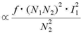
![]()
![]()
![]()
![]()
![]()
![]()
![]()
![]()
![]()
![]()
단락 회로 전류는 M/L에 비례한다는 것과 권선 수에 독립적이라는 점을 유의한다.Note that the short-circuit current is proportional to M / L and is independent of the number of windings.

여기서 k는 1차측 및 2차측(즉 송신기 및 수신기) 사이의 자기 결합 인자(magnetic coupling factor)이다. 앞에서 언급했듯이, 다른 동작 주파수에서도 상기 수신기 유도 전압과 비보상 전력은 동일해야 한다. 이는 또한 상기 단자 전압과 단락 회로 전류 역시 같아야 함을 의미한다. 수학식 1 및 2는 같은 비보상 전력 및 유도 전압과 다른 동작 주파수에 대해 수학식 5 및 6과 같이 각각 다시 쓰여질 수 있다. 여기서Na는 첫 번째 동작 주파수에 대한 권선 수이고, Nb는 두 번째 동작 주파수에 대한 권선 수이고, Ia 및 Ib는 각각의 전류이다.Where k is the magnetic coupling factor between the primary and secondary (i. E., Transmitter and receiver). As mentioned above, the receiver induced voltage and the non-compensated power must be the same at different operating frequencies. This also means that the terminal voltage and the short circuit current should be the same.
![]()
![]()
![]()
![]()
수학식 5로부터:From equation (5): <

수학식 6 및 7을 이용하여:Using Equations (6) and (7): <

수학식 7 및 8을 이용하여:Using Equations (7) and (8): <

수학식 5 내지 9는, 1차측 전류(즉 송신기 코일에서의 전류)가 동일하게 유지되고 권선 턴(turn)이 수학식 8에 따라 변화되는 반면, 다른 주파수에 대해서 픽업 비보상 전력 및 Voc 가 같을 것이라는 것을 지시한다. 예를 들어, 38.4 kHz에서 작동하도록 설계된 송신기와 수신기 모두에서 15 턴(turn)을 가진 두 모듈의 배열은, 수신기 VOC와 비보상 전력이 같도록 20 kHz에서 21로 증가된 권선 수를 갖는 것이 필요할 것이다. 다시 말해, 이러한 특징은 동일한 자기적 설계를 갖는 모듈들이 다른 주파수에서 사용될 수 있도록 한다. 그리고, 단지 권선 수의 스케일링(scaling)에 따라 수신기 모듈 출력 특성이 동일하게 유지될 수 있다. 하지만, 수학식 10에서 보이는 바와 같이, 상기 코어 자속은 권선 수 및 전류에 비례한다. 따라서 상기 전류를 일정하게 유지하고 상기 권선 수를 변화시키는 것이 코어 자속과 그에 따른 자속 밀도를 변동시킬 것이다. 수학식 8을 수학식 10으로 치환하면, 코어 내의 자속이 [루트fa/fb]에 비례하여 변하는 것을 볼 수 있는데, 이는 수학식 8과 등가이다. 따라서, 동작 주파수가 하향 스케일되면, 페라이트 포화를 막기위해 상기 페라이트 코어의 단면적이 증가될 필요가 있을 수 있다. 단면적의 증가는 바람직하게는 페라이트 코어의 두께를 중가시킴으로써 이루어질 수 있고, 상기 모듈의 자기 저항(magnetic reluctance) 경로가 거의 동일하게 유지된다.

![]()
![]()
여기서 Rm 은 자속 경로의 자기 저항(magnetic reluctance)이다.Where R m is the magnetic reluctance of the flux path.
상기 코어에 대한 맴돌이 전류(eddy current) 손실(Pe) 및 히스테리시스(hysteresis) 손실(Ph) 식이 수학식 11 및 12에 W/m3 단위로 주어진다. 페라이트 코어의 단면적이 동일하게 유지된다면, 두 다른 주파수에 대한 맴돌이 전류 손실 대 히스테리시스 손실 비율은 수학식 13 및 14에서 주어진다.The eddy current loss (Pe) and hysteresis loss (Ph) for the core are given in units of W / m3 in Equations (11) and (12). If the cross-sectional area of the ferrite core is kept the same, the eddy current loss versus hysteresis loss ratio for two different frequencies is given in equations (13) and (14).


여기서n은 물질에 대한 스타인메츠 계수(Steinmetz coefficient)이고 일반적으로 1.6 ~ 2의 범위에 있다.Where n is the Steinmetz coefficient for the material and is typically in the range of 1.6-2.


상기의 표현은 동일한 단면적 및 부피에 대한 상기 코어의 히스테리시스 손실은, 주파수와 무관하게 일정하게 고정되지만 상기 코어의 맴돌이 전류 손실은 동작 주파수의 감소에 비례하여 감소한다는 것을 시사한다. 페라이트 코어에서의 전체적인 전력 손실이 그 히스테리시스 손실에 의해 지배되기 때문에, 동작 주파수 스케일링 과정에서, 코어 자속 밀도 외에 충전기 패드의 대부분의 속성이 거의 동일하게 유지될 것이다.The above expression suggests that the hysteresis loss of the core to the same cross-sectional area and volume is fixed constant regardless of frequency, but the eddy current loss of the core decreases in proportion to the decrease of the operating frequency. Since the overall power loss in the ferrite core is dominated by its hysteresis loss, in the operating frequency scaling process, most of the properties of the charger pads will remain approximately the same except for the core magnetic flux density.
하지만 이전에 논의했듯이, 낮은 주파수에서 동작의 트레이드 오프(trade off)는 [루트fa/fb]에 의한 코어 내 자속 밀도의 증가이다. 따라서, 더 높은 자속 밀도를 수용하기 위해, 상기 자속 밀도를 동일하게 유지하기 위해 상기 페라이트 단면적이 증가되어야 한다. 이러한 증가된 페라이트 부피와 자속 밀도의 유지로서, 페라이트 내의 전력 손실은 아래에 보여지듯이 낮아질 것으로 기대된다. 수학식 11 및 12는 맴돌이 전류 손실 및 히스테리시스 손실을 watt per m3 단위로 표현한다. 따라서, 총 맴돌이 전류 손실 대 히스테리시스 손실은, 각각 수학식 15 및 16에 나타낸 상기 페라이트 부피(A*L)를 고려해야 한다. However, as discussed previously, the trade off of operation at low frequencies is an increase in magnetic flux density in the core by [root fa / fb]. Therefore, to accommodate the higher magnetic flux density, the ferrite cross-sectional area must be increased to keep the magnetic flux density the same. As a result of maintaining this increased ferrite volume and magnetic flux density, the power loss in the ferrite is expected to be lowered as shown below.

여기서 L은 충전기 패드 페라이트 코어의 길이이고 일정하게 유지된다.Where L is the length of the charger pad ferrite core and is kept constant.
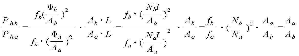
앞서 설명한, 충전기 패드 동작 주파수가 38.4 kHz부터 20 kHz까지 스케일된 예를 참조하면, 페라이트 영역은, 상기 자속 밀도를 유지하기 위해 1.385 V(38.4 kHz/20 kHz)의 인자(factor)로 증가될 필요가 있을 것이다. 따라서 20 kHz에서 동작할 때 상기 충전기 패드의 상기 맴돌이 전류 및 히스테리시스 손실은, 같은 코어 자속 밀도에서 38.4 kHz에서 동작할 때와 비교하여 각각 37.59% 및 72.17% 감소될 것이다.Referring to the example described above in which the charger pad operating frequency is scaled from 38.4 kHz to 20 kHz, the ferrite area needs to be increased to a factor of 1.385 V (38.4 kHz / 20 kHz) to maintain the magnetic flux density . Thus, when operating at 20 kHz, the eddy current and hysteresis losses of the charger pads will be reduced by 37.59% and 72.17%, respectively, compared to operating at 38.4 kHz at the same core flux density.
모듈 성능의 시뮬레이션 예Simulation example of module performance
이제 도 21 내지 도 28을 참조하여, 본 발명에 따른 결합된 전력 전송 모듈들의 시뮬레이션이 가능한 실시예 및 그 용도의 예시를 제공하기 위하여 기술된다. 상기 예시에서 전력 전송 모듈들의 결합된 시스템은 수신기 권선 개방 회로와 함께 시뮬레이션된다. 도 21은 상기 페라이트 코어의 배열을 도시한다. 페라이트 코어는 기본적으로 매우 가까운 피팅(fitting)을 제공하기 위한 페라이트 그라운드의 93 x 28 x 16 mm 블록들이고, 서로 접착된다. 상기 페라이트는, 페라이트와 알루미늄 사이에 8 mm 공간을 가지고 알루미늄 벽으로 둘러싸이고, 알루미늄 백킹 플레이트(backing plate) 위로 5 mm 에 있다. 23A 전류를 가지고 자기적으로 직렬, 전기적으로 병렬로 구동되는 2 코일이 있는 상황에서 구동되는 패드(즉, 전력 공급기와 연결된 패드)에 대한 자속 플롯(flux plot)이 도 22에 도시된다. 상기 환경에서 페라이트 중간을 지나는 자속 밀도는 도 23에 도시된다. 도시되었듯이 상기 “자속 파이프”는 자속을 패드의 한 쪽 끝에서 다른 쪽 끝으로 운반하는 데에 매우 효과적이다. 특히, 도 25내지 26으로부터, 본질적으로 상기 패드들 사이의 영역 너머로 누설 자속이 없음을 볼 수 있다.21 to 28, a simulation of combined power transmission modules according to the present invention is described to provide a possible embodiment and an example of its use. In this example, the combined system of power transmission modules is simulated with a receiver winding open circuit. Figure 21 shows the arrangement of the ferrite core. The ferrite cores are essentially 93 x 28 x 16 mm blocks of ferrite ground to provide very close fitting and are bonded together. The ferrite is surrounded by an aluminum wall with an 8 mm space between the ferrite and the aluminum and 5 mm above the aluminum backing plate. A flux plot for a pad (i.e., a pad connected to a power supply) driven in the presence of two coils driven magnetically in series and electrically parallel with a 23 A current is shown in FIG. The magnetic flux density passing through the middle of the ferrite in the above environment is shown in Fig. As shown, the " magnetic flux pipe " is very effective in transporting the magnetic flux from one end of the pad to the other. In particular, it can be seen from Figures 25 to 26 that there is essentially no leakage flux beyond the area between the pads.
결합된 모듈들에 대한 단면이 도 24에 도시되고, 다른 그림들은 상기 시스템의 성능을 설명하기 위해 상기 단면을 따른 측정값들을 이용한다. 패드들 사이의 간격이 100 mm일 때 자속 선(flux line)들이 도 25에 도시되고, 간격이 200 mm 일 때는 도 26에 도시된다. 상기 페라이트 내의 자속 밀도는 도 28에 도시된다. 시뮬레이션들이 나타내듯이, 상기 자속 파이프는 자속을 패드의 한 쪽 끝에서 다른 쪽 끝으로 효율적으로 운반하고, 두 패드 사이의 양호한 자기적 커플링을 제공한다. 결합된 패드들에서의 자속 밀도는 도 28에 도시된다. 구동되는 패드에서의 최대 자속 밀도는 약 0.2 T 이고, 이는 상기 페라이트의 포화보다 문제없이 낮다. 픽업 패드에서의 자속 밀도는 더 낮지만, 픽업이 공진될 때, 대략 송신기 패드와 실질적으로 같아질 만큼 증가할 것이다.A cross section for the combined modules is shown in FIG. 24, and other figures use measurements along the cross-section to illustrate the performance of the system. The flux lines are shown in FIG. 25 when the spacing between the pads is 100 mm, and shown in FIG. 26 when the spacing is 200 mm. The magnetic flux density in the ferrite is shown in Fig. As the simulations show, the magnetic flux pipe efficiently conveys the magnetic flux from one end of the pad to the other and provides good magnetic coupling between the two pads. The magnetic flux density at the coupled pads is shown in FIG. The maximum magnetic flux density in the driven pad is about 0.2 T, which is lower than the saturation of the ferrite without problems. The magnetic flux density at the pick-up pads is lower, but when the pick-up is resonated, it will increase substantially to be substantially equal to the transmitter pad.
다른 전력 전송 모듈 실시예Other Power Transmission Module Embodiments
상기의 모듈 배열과 같이, 이 실시예에서의 모듈들도, 동일한 설계의 다른 배열을 사용한 원하는 자속 경로를 제공하기 위해서, 높은 투자율(permeability)의 코어를 사용한다. 상기 코어를 통해 자속이 운반된다. 실질적으로 평평한, 즉 평면(flat) 코일들이 상기 자속 코어의 위에 놓인다. 따라서, 상기 코일들을 통과하는 상기 코어를 통하는 직선 경로는 없다. 이상적으로, 2개의 코일이 서로 매우 근접하게 있어야 한다. 완전한 배열이 도 29a 내지 29c에 도시된다. 상기의 도면들을 참조하면, 이러한 배열에서 상기 2개의 코일들(17)은 기본적으로 중심 선(17A)를 따라 접촉한다. 그리고 약간 중첩될 수 있다. 상기 자속 파이프(10)는 코어(14)를 포함하고, 상기 코일들(17)의 끝까지 신장된다. 상기 코일들 또는 권선들(17)은 실질적으로 평평한 평면이다. 그리고 실질적으로 상기 코어(14)의 일 면 위의 같은 평면(즉, 동일 평면상)에 배열된다. 일 실시예에서, 상기 코어(14)는 상기 코일들(17)의 중심선을 따라 제공되고, 각 코일의 중앙에 구멍을 지나 적어도 A로 지시된 위치까지 신장되어야 한다. 상기 코어(14)는 상기 코일(17) 아래에서 B 위치 또는 더 멀리까지 신장될 수 있다. 코일들(17) 안에 구멍들은 폴 영역(pole area)들로 동작한다. 폴 영역(pole area)들은 1차 또는 픽업 모듈을 위한 수신기/송신기(11 및 12)이다. 일 실시예에서, 상기 코어(14)는 스트립(도 29a 내지 29c에 미도시)들 내의 페라이트 바(bar)들로 만들어진다. 그리고 제조를 단순화하기 위해 스트립들 사이의 에어-갭(air-gap)이 허용된다. 이상적인 자속 경로들(20)이 도 29c에 도시되고, 상기 코어(14)의 일 면에만 존재한다. ? 이상적인 상황. 이론상으로 상기 배열(즉, 코일들(17)이 탑재된 면과 마주보는 상기 코어(14)의 일 면)의 뒤쪽 바깥으로 어떤 자속도 없고 그에 따라 알루미늄 스크린(screen)이 필요하지 않다. 하지만, 상기 코어(14)를 포함하는 페라이트 바 내의 오류 및 불완전이 (방지되었어야 할) 작은 누설 자속을 발생시킬 수 있기 때문에, 실제적으로는 몇몇 실시예에서 가벼운 스크린이 사용될 수 있다.Like the above module arrangement, the modules in this embodiment also use a core of high permeability to provide the desired flux path using different arrangements of the same design. The magnetic flux is carried through the core. Substantially flat, i.e. flat coils, lie on top of the flux core. Thus, there is no straight path through the core through the coils. Ideally, the two coils should be very close together. A complete arrangement is shown in Figures 29A-29C. With reference to the above figures, in this arrangement the two
누설 자속이 매우 작기 때문에, 바로 위에서 설명한 배열에 따른 유도 전력 전송 모듈들은 매우 쉽게 사용될 수 있다. 그것들은 성능에 손실 없이 금속 물체에 아주 가까이 놓여질 수 있다. 그리고 연결 도선 등에 의해 크게 영향받지 않는다.Because the leakage flux is very small, the inductive power transfer modules according to the arrangement just described above can be used very easily. They can be placed very close to metal objects without loss of performance. And is not significantly influenced by the connecting wire or the like.
추가적인 실시예에서, 차량에 수평으로 탑재된 수신기 또는 송신기 모듈 내의 상기 코일들의 배열은, 픽업(즉, 수신기)이, 자속 발생기(수평 지향된 송신기 모듈)에 대하여 세로로 지향된(즉, 코어(14)와 평행한 방향을 갖고, 참조 도면에서 X축 방향인) 상기 자속의 첫 번째 방향에 민감하게 만든다. 오정렬(misalignment)에 대한 수신기의 자기 커플링을 향상시키기 위해서, 고정된 송신기에 대하여 실질적으로 수직인 자속의 두 번째 성분에 민감한 “두 번째” 코일이 배치될 수 있다. In a further embodiment, the arrangement of the coils in a receiver or transmitter module mounted horizontally in the vehicle is such that the pickup (i. E. Receiver) is oriented vertically with respect to the flux generator (horizontally oriented transmitter module) 14) and is sensitive to the first direction of the magnetic flux, which is the X-axis direction in the reference drawing. To improve the receiver's magnetic coupling to misalignment, a " second " coil sensitive to the second component of the flux substantially perpendicular to the fixed transmitter may be placed.
도30은, 중앙에 위치한, “수평” 자속에 민감한 코일(22) 및 수직 성분에 민감한 두 번째 코일을 만들기 위해 다른 위상으로 연결된 바깥쪽 2개 코일(17)을 갖는 수신기의 추가적인 실시예를 나타낸다. 이러한 전기적 연결은 도 30에 명확히 도시되지 않는다. 그러나 도 31에 명백하게 도시된다.Figure 30 shows a further embodiment of a receiver with a
도 29a 내지 29c의 수신기를 위한 두 번째 평면 코일(flat coil)(22)이, 도 32a 및 32b에 도시된 상기 필드의 수직 성분에 민감한 적절한 배치로써, 상기 코어 위에 놓여질 수 있다. 본래의 픽업 구조에서와 같이, 이러한 추가적 코일은 상기 코어(14)의 일 면에만 존재하고, 그에 따라 송신기를 향해 지향된 수신기의 일 면 위의 자속 선(flux line) 모두를 이상적으로 유지시킨다.A second
도 32a 및 32b에 도시된 바와 같이, 수신기 만이 중앙의 직각 코일(quadrature coil)(22)로 변형된다. 이러한 두 번째 코일은 특히 X-방향 (즉, ㅅ수평 길이 방향)에서의 오정렬에 민감하나, Y-방향(코어(14)에 수직 인 수평 횡 방향)에 대해서는 그렇지 않다. 이는 Y-방향의 오정렬에는 민감하지만, 그 구조상 X-방향의 움직임에는 민감하지 않은 본래의 수신기를 보완한다. 두 수신기 코일의 결합된 출력은, 수신기의 민감도를 향상시키고, 수신기가 이상적인 위치에 놓여 필요한 전력을 커플링하도록 한다. 또한 도 32a 및 32b는 코어(14)를 포함하는 이격된 페라이트 로드(rod) 또는 바(bar)(24)의 배치를 나타낸다.As shown in FIGS. 32A and 32B, only the receiver is transformed into a
일 예로서, 어떤 형태의 보상없이 도 32a 및 32b에 도시된 바와 같이, 상기 모듈 설계를 사용한 자속 선들이 도 33b 및 33a에 오정렬과 함께 및 오정렬 없이 도시된다. 여기서 상기 송신기 및 수신기들은 수신기에 두 번째 “수직 자속” 코일(즉, 도 32a및 32b의 코일(22))이 추가되는 점 외에는 동일하다. 상기 송신기 및 수신기 모두는 길이 및 406mm 폭을 갖고, 수직으로 200mm 이격되어 있다. 송신 코일내의 전류는 20kHz에서 23 A이다. 특히 상기 자속의 대부분은 상기 송신기와 수신기 사이에 존재한다. 반면 매우 작은 누설 자속이 이 영역 바깥에 존재함이 보여진다. 도 33a에서 이러한 자속 선들은 첫 번째 수신기 코일에 커플링된다. 반면 도 33b에서 상기 자속 선들의 대부분은 두 번째 수신 코일에 커플링되어, 상기 수신기의 출력 전력 능력을 향상시킨다.As an example, flux lines using the modular design are shown in Figures 33b and 33a with misalignment and without misalignment, as shown in Figures 32a and 32b without any form of compensation. Where the transmitter and receivers are identical except that a second " vertical flux " coil (i.e.,
도 34 및 35에, 오정렬을 갖는 또는 오정렬을 갖지 않는 수신기 코일들의 출력으로부터 발생된 VA가 도시된다. 상기 수신기가 X 방향으로 (송신기 위의 중앙인, 그 이상적인 위치에 비해) 오정렬 되었을 때, 도 32a 및 32b에 도시된 모듈들의 자기적 시뮬레이션으로부터 수신기 코일들의 총 기여 및 부분 기여 VA가 도 34에 도시된다. 도 34에서 곡선 26은 코일()의 VA 기여를 나타내고, 곡선 28은 코일들(17)의 결합된 VA 기여를 나타내고, 나머지 곡선은 코일들(17 및 22)의 합산 형태를 나타낸다. 지적한 바와 같이, 0 X-옵셋에서 2kW 출력이 필요한 경우에, 필요한 전기적 튜닝이 VA 출력을 약 3.2까지 승압(boost)시킬수 있도록, 두 번째 코일(22)은 실질적으로 출력을 향상시킨다. 140mm X-옵셋에서 코일(22)없을 때 필요한 전기적 승압(boost) (Q)는 17 회 이상(이는 요구되는 튜닝의 민감도 때문에 실제적으로 어렵다)이다. 이에 반해 코일(22)이 있을 때는 약 4.8의 효과적인 승압이 요구되고, 이는 쉽게 달성된다. 34 and 35, the VA generated from the output of the receiver coils with misalignment or without misalignment is shown. The total contribution and partial contribution VA of the receiver coils from the magnetic simulation of the modules shown in Figs. 32A and 32B when the receiver is misaligned in the X direction (relative to its ideal position, centered on the transmitter) do.
코일(22)은 상기 수신기가 X 방향에 0 옵셋을 가지고 위치되었을 때, Y 방향에서 민감할 것이 기대되지 않는다. 이는. 상기 코일(22)로부터의 총 전력에 대한 기여가 없음을 나타내는 도 35에 도시된 자기 시뮬레이션에서 증명된다. 하지만, 코일들(17)의 결합된 출력이 당연히 이 방향으로 민감하기 때문에, 상기의 것들은 요구되지는 않는다. Y 방향의 140mm 옵셋에서, 약 5.5의 전기적 튜닝(Q)을 가지고 2kW 출력이 가능하다.
실제에서, 모듈의 단자에서의 전압이 불안전한 레벨까지 이르지 않을 것을 보장하는 것에 신중해야 한다. 그러므로 몇몇 실시예에서, 모듈 단자들에서 보이는 인덕턴스를 낮추고, 그에 따라 이 단자들에서의 전압을 적절한 한계 (약 300~400V)이내로 제어하기 위해 커패시턴스가 모듈내의 권선들에 직렬로 추가될 수 있다. 이것이 없으면 상기 단자 전압은 수 kV가 될 수 있고, 이는 원하지 않은 값이며 위험할 수도 있다. 상기 커패시턴스는 장치내의 편리한 위치에 상기 권선들과 직렬로 위치할 수 있다. 따라서 몇몇 실시예에서, 하나 이상의 커패시터가 상기 모듈 하우징(housing)내의 단자 점에서 상기 권선들과 직렬로 놓일 수 있다. 그리고, 다른 실시예에서 커패시터들은, 싱글 코일의 내부 전압이 너무 높은 경우에. 권선들을 직렬 커패시턴스르 가지고 적절한 구역으로 분리함으로써, 권선을 따라 분산될 수 있다.In practice, care must be taken to ensure that the voltage at the terminals of the module does not reach unsafe levels. Therefore, in some embodiments, capacitance may be added in series to the windings in the module to lower the inductance seen at the module terminals, and thus control the voltage at these terminals to within the appropriate limits (about 300-400 V). Without this, the terminal voltage can be several kV, which is an undesired value and may be dangerous. The capacitance may be located in series with the windings at a convenient location within the device. Thus, in some embodiments, one or more capacitors may be placed in series with the windings at a terminal point within the module housing. And, in another embodiment, the capacitors are in a state where the internal voltage of the single coil is too high. Can be dispersed along the windings, by separating the windings into the appropriate zones with the series capacitances.
또한, 사용중인 장치 주위에 있을 수 있는 표유(stray) 필드에 대한 실제적인 이슈가 있다. 그러므로, 몇몇 실시예에서, 표유 필드를 흡수하기 위해 강철 또는 다른 흡수재가 부가될 수 있다. 수신기로 전력을 전송하기 위해 바닥 위에 마련된 전력 전송 모듈의 예에서, 상기 바닥과 모듈 베이스의 알루미늄 사이에 강판이 제공될 수 있다. 이러한 방법에서 상기 강철(또는 다른 손실성(lossy) 금속 물질 또는 탄소 섬유)은 주변에 원치않는 자기 필드를 방지하기 위해서 표유 필드를 흡수하여, 상기 장치가 ICNIRP 기준(6.25uT) 내에 들도록 보장한다. 이것은 몇 와트를 흡수하지만 필드들이 설계된 영역 밖으로 방출되지 않도록 보장한다. 본질적으로 상기 알루미늄 플레이트의 크기와 상기 강철 또는 다른 손실성 물질의 치수는 적합하게 조정될 수 있다. 그리고, 여러 개의 모듈이 있는 영역에서는, 하나의 손실성 판이 사용되고, 모듈들은 필요에 따라 그 위에 놓일 수 있다. 유사하게, 유도적으로 전력을 수신하기 위해 차량의 아래에 탑재된 모듈은, 차량 몸체의 강철이 표유 필드를 흡수하기 위해 사용되거나, 또는 ICNIRP 기준을 만족시키기 위해 필요한 만큼 강철이 부가되는 방식으로, 탑재될 수 있다.There is also a real issue with stray fields that may be around the device in use. Therefore, in some embodiments, steel or other absorbent material may be added to absorb the stray field. In the example of a power transmission module provided on the floor for transmitting power to the receiver, a steel sheet may be provided between the floor and the aluminum of the module base. In this way, the steel (or other lossy metallic material or carbon fiber) absorbs the stray field to prevent unwanted magnetic fields around it, ensuring that the device is within the ICNIRP standard (6.25 uT). This absorbs a few watts but ensures that the fields are not emitted outside the designed area. Essentially, the size of the aluminum plate and the dimensions of the steel or other lossy material can be suitably adjusted. And, in the area where there are several modules, one lossy board is used, and the modules can be placed on it as needed. Similarly, a module mounted under the vehicle for inductively receiving power may be used in such a manner that the steel of the vehicle body is used to absorb the stray field, or steel is added as needed to meet the ICNIRP standard, Lt; / RTI >
또한 자기 차폐가 도로의 안 또는 위에, 또는 차량의 안 또는 위에, 표유 자기 필드를 흡수하여 감소시키기 위해 제공될 수 있다. 또한 차폐는 송신 및/또는 수신 모듈의 주위에 제공될 수 있다. 적절한 차폐는 적절한 금속에 부가된 손실성 자기 페인트 또는 물질을 포함하고, 도로에는 철근을 포함할 수 있다.Also, magnetic shielding may be provided to absorb and reduce stray magnetic fields, either inside or on the road, or inside or onto the vehicle. Shielding may also be provided around the transmitting and / or receiving module. Proper shielding may include lossy magnetic paint or material added to the proper metal, and may include reinforcing bars in the roadway.
도로 구동 전기 차량 시스템의 일 실시예에서, 하나 이상의 전력 송신 모듈들이, 차선 중앙의 슬롯에 놓여지고, 자기 필드의 통과는 허용하지만 그 위로 지나가는 트럭과 버스의 무게 및 충격을 견딜 수 있는 강한 커버로 덮인 도로 유닛에 공급된다. 상기 커버는 상기 유닛 또는 모듈의 주요한 부분일 수 있다는 것이 인정될 수 있다. 상기 커버 또는 유닛은 세라믹 물질 또는 콘크리트일 수 있다.In one embodiment of a road-driving electric vehicle system, one or more power transmission modules are placed in a slot in the center of the lane, with a strong cover to withstand the weight and impact of the truck and bus passing over it but allowing passage of the magnetic field Is supplied to the covered road unit. It can be appreciated that the cover can be a major part of the unit or module. The cover or unit may be a ceramic material or concrete.
보통의 동작에서, 차량들은 이러한 전력 송신 모듈의 양 쪽에 걸친다. 그리고 전력은 각 도로 전력 모듈에서 발생된 자기 필드를 이용하여 상기 차량들의 적절한 수신기로 전달된다. 전력 공급기에서 전력 모듈로 가는 모든 전력은, 20 kHz, 125A의 완전 절연된 배전선에 의해 이송된다. 안전성 문제로, 3상 설비는 도로에 사용할 수 없다. 도로에 사용할 수 있는 상기 20 kHz 전력 출력은, 비교적 낮은 장애 전류(fault current)를 갖고, 사람에 대한 전기 충격이 불가능한 주파수에서 있다. 상기 시스템은, 시스템을 안전하게 하는, 수 개의 절연 레벨 및 3개의 격리(isolation) 레벨을 갖는다.In normal operation, vehicles run on both sides of this power transmission module. And power is transmitted to the appropriate receivers of the vehicles using the magnetic field generated in each road power module. All power from the power supply to the power module is carried by a fully insulated distribution line of 20 kHz, 125 A. For safety reasons, three-phase equipment can not be used on the road. The 20 kHz power output available on the road is at a frequency that has a relatively low fault current and is not capable of shocking people. The system has several isolation levels and three isolation levels, which make the system secure.
시간 변화 회전 필드(time varying rotating field)를 이용한, 넓은 가로(lateral) 허용오차를 위한 다위상(Multiphase) 구조Multiphase structure for wide lateral tolerances using a time varying rotating field
도로을 위한, 그리고 고속도로를 따라 운행할 때의 더 넓은 가로 방향 허용 오차(tolerance)를 주기 위한 대안적 실시예에서, 정격이 각각 70 내지100 kW 사이이고, 바람직하게는 정규 간격으로 200m 떨어진 2개 이상의 전력 공급기가 사용될 수 있다. 각 공급기는 상당 50/60 Hz 400/480 V인 3상 공급 설비에 연결되고, 약 100미터에 동력을 공급한다. 여기서 각 공급기는 연속적인 트랙 루프에서 20 kHz 주파수의 125 A 전류를 공급하도록 설계된다. 하지만 이러한 두 번째 실시예에서, 각 전력 공급기의 출력은 (각 정의된 위치에 있는 다른 공급기와) 동기화(synchronized)되고, 출력 전류의 위상이 미리 정의한 분리(separation)를 갖도록 제어된다. 일 실시예에서, 공급기/트랙 및 컨트롤러의 수를 최소화하기 위해 2-위상 시스템만이 요구된다. 그런 다음, 2-위상 시스템은 각 송신선의 전류가 90도 위상차가 갖도록 제어되기를 요구한다. 몇몇 실시예에서 3상 시스템이 바람직하다는 것이 발견된다면, 각 전류의 위상이 120도 분리되도록 제어되는 주파수 및 위상 모두에서 동기화된 출력 전류를 공급받는, 3개의 전력 공급기들 및 3개의 송신 선들이 제공될 것이다.In an alternative embodiment for providing a greater lateral tolerance for roads and along highways, it is preferred that two or more of the rated values are between 70 and 100 kW each, preferably 200 m apart at regular intervals A power supply may be used. Each feeder is connected to a three-phase feeder with a corresponding 50/60
이전의 실시예에서와 같이, 전력 모듈들(411)은, 도 36에 도시된 것처럼, 각 송신 시스템(102)과 유도적으로 결합된다. 2-위상 시스템(여기서 더 선호되는)의 경우에, 상기 전력 모듈(411)의 상기 코일 및 페라이트 배열(401)은, 동일한 리츠 선(Litz wire)으로 만들어진 N 턴(turn)을 갖는 2 위상 권선 인덕턴스들(403)을 포함한다. 상기 인덕턴스들은 전기적으로 이격되고, 0, +90, +180 및 +270도에 위치된 4개의 도선(wire) 그룹들을 효과적으로 만드는 바이폴라(bipolar) 방식으로 중첩된다. 상기 실시예에서, 설명된 4개의 도선 그룹들은 도로를 가로질러, 즉 한 쪽에서 다른 쪽 방향으로, 가로로 정렬된다. 하지만 다른 실시예에서, 덜 선호되지만, 상기 도선 그룹들은 도로를 따라 세로로, 즉 도로를 따라 이동하는 방향과 평행하게 지향될수 있다. 끝 대 끝으로 놓인 페라이트의 각편(piece)들을 사용하여 만들어진 페라이트 스트립(Ferrite strip)들(402)은, 그 위에 코일들(403)이 놓이는 상기 전력 모듈의 뒷면을 가로질려 놓여진다. 상기 페라이트는, 위에서 도 15 내지 35와 관련하여, 그리고 도 2a 및 2b에 도시한 단위상(single phase) 전력 전송 모듈(109)에 대하여 설명한 것과 유사한 방식으로, 어떤 다른 잠재적 자속 경로를 도로에서 차단하는 반면 도로 위의 자속을 증가시키는 동작을 한다.As in the previous embodiment, the power modules 411 are inductively coupled to each
모듈 부품(401)내의 각 위상 권선(403)은 그 자신의 제어 회로로부터 구동된다. 상기 제어 회로는 위의 단위상 실시예에서 설명한 바와 같은 적절한 픽업(송신 도선 중 하나와 유도적으로 결합되어 구동되는), 튜닝 및 AC 컨트롤러를 포함한다. 몇몇 실시예에서 상기 모듈(411)은 단순히 별도로 공급된 제어 및 튜닝 요소, 부품(401)을 포함할 수 있다. 또한 대안적인 실시예에서, 부품(401)은 전력 공급기에 직접 연결될 수 있다. 즉 위상 분리된 전력 공급기에 유도적으로 결합되지 않을 수 있다.Each phase winding 403 in the module component 401 is driven from its own control circuit. The control circuit includes an appropriate pickup (driven inductively coupled with one of the transmission leads), tuning and an AC controller as described in the above unitary embodiments. In some embodiments, the module 411 may simply include separately supplied control and tuning elements, component 401. Also in an alternative embodiment, the component 401 may be directly connected to the power supply. That is, not inductively coupled to the phase separated power supply.
도 36에 도시된 실시예의 동작에서, AC 컨트롤러는 동일하게 조정된(tuned) 전압을 각 회로의 병렬 조정된 커패시터(105)를 가로질러 공급한다. 일 실시예에서, 다위상(multiphase) 모듈은 명목상 0.75m 내지 1.5m의 폭 및 0.5m에서 2m 사이의 길이(어떤 응용에서는 5m 길이 구역 또는 더 큰 것이 적절할 수도 있지만)를 갖도록 구성될 수 있다. 또한 이러한 모듈의 깊이는 (단위상 실시예와 관련하여 위에서 설명한) 도로 유닛을 포함하는지 여부에 따라, 40-150mm로 기대된다. 이러한 도로 모듈 또는 유닛은 바람직하게는 도로 중앙을 따라 위치된다. 그러나 어떤 응용에서는 전체 차선을 가로질러 놓일 수 있다. In the operation of the embodiment shown in FIG. 36, the AC controller supplies an equally tuned voltage across the parallel tuned
다위상 바이폴라(bipolar) 전력 패드 구조의 추가적인 실시예들이 도 41 내지 49를 참조하여 설명된다. 일반적인 패드 구조는 도 32a 및 32b에서 설명된 것과 유사함에도 불구하고, 설명의 명확성을 위해 다른 참조 번호가 사용된다.Additional embodiments of a multiphase bipolar power pad structure are described with reference to Figures 41-49. Although the general pad structure is similar to that described in Figs. 32A and 32B, other reference numerals are used for clarity of explanation.
도 41을 참조하면, 자속(magnetic flux) 패드(pad)의 구조가 도시된다. 편의상 이러한 일반적인 구조를 본 명세서에서는 DDP로 호칭한다. 그리고 도 41 내지 49와 적절하게 연결된 곳에서 일반적으로 DDP로 언급된다.Referring to Figure 41, the structure of a magnetic flux pad is shown. For convenience, this general structure is referred to herein as DDP. And where it is properly connected to Figures 41-49, it is generally referred to as DDP.
도 41에 도시된 상기 DDP 패드는, 코어(804)와 자기적으로 관련되고 코어(804)위에 위치한, 실질적으로 동일 평면상의 두 코일들(802, 803)을 일반적으로 포함한다. 도면에서 보이는 대로, 상기 코어(804)는 서로 떨어져 병렬로 배열된, 소정의 길이를 갖는 페라이트(ferrite) 스트립(strip) 또는 바(bar)(805)와 같은 투과성 물질들의 다수로 구성될 수 있다. 상기 패드 구조는 상기 코어 아래에 플레이트(806)를 포함할 수 있다. 그리고 상기 플레이트 아래에 스페이서(807)를 포함할 수 있다. 몇몇 실시예에서 상기 평면 코일(802,803)의 다른 면에 커버(808)가 제공될 수 있다. 상기 패드의 주변에 패딩(padding)(809)이 제공될 수 있다. 보이는 바와 같이 상기 코일들(802, 803)은 폴 영역들(pole area)(810, 811)을 각각 정의한다. 도 41에서 보이는 이러한 DDP 패드 구조는, 차량 충전과 같은 IPT 전력 전송 응용에 적합한 매우 양호한 특성을 보여준다. 상기 코일들(802, 803)은 다른 위상으로(out of phase) 연결되고, 양호하게 커플링된 전기 차량 전력 전송에 적절한 거리에서 수신기(예컨대 실질적으로 같게 자기적 설계된)와의 연결(couple)을 위한 정적 시변 자기장(stationary time varying magnetic field)을 생성하기 위해 싱글 인버터에 의해 구동될 수 있다.The DDP pad shown in FIG. 41 generally includes two
도 42를 보면, 도 41에서의 DDP에 직각 코일(quadrature coil)(812)를 더 포함하는 구조가 도시된다. 이는 도 40 내지 49와 관련된 적절한 곳에서 DDPQ 패드로 호칭된다. 상기 직각 코일은, 적합한 인버터에 의해 동력이 공급되었을 때의 도 41의 DDP 패드와 같은 자속 발생기에 대하여, 도 42에 도시한 구조에 측면 움직임이 있을 때 전력 전송 프로파일을 확장한다. 상기 직각 코일은, 수신기 패드가 차단(intercept)하는 자기장의 “수직(vertical)” 성분으로부터 전력이 추출되도록 한다. 반면 다른 코일들(802, 803)은 상기 차단된 자속의 “수평(horizontal)” 성분으로부터 전력을 추출한다. 따라서, 도 42의 구조는 자속 수신기에 적합하다.42, there is shown a structure further comprising a
도 43을 보면, 본 명세서에서 바이폴라(bi-polar) 패드 또는 BPP 패드로 호칭되는 또 다른 구조가 도시된다. 상기 BPP 패드는 상기의 도 41 및 42에서 설명한 DDP 패드와 유사한 구조를 갖는다. 상기 BPP 패드는 전기 차량의 충전 및 구동에 적합한 거리에서 2차 수신기와 우수하게 커플링(coupling) 가능하도록 한다.43, another structure is referred to herein as a bi-polar pad or a BPP pad. The BPP pad has a structure similar to the DDP pad described in FIGS. 41 and 42. FIG. The BPP pad allows excellent coupling with the secondary receiver at a distance suitable for charging and driving the electric vehicle.
상기 BPP 패드는, 알루미늄 플레이트(aluminium plate)(807), 유전체 스페이서(dielectric spacer)(806), 4열의 페라이트 바(ferrite bar)(805)를 포함하는 코어(804), 실질적으로 동일 평면상에 있으나, 중첩(overlap)되고, (실제적으로는 리츠 선(Litz wire)을 권선하는 용이성 때문에 더 타원형이지만) 이론적으로 직사각형(rectangular) 형상인, 측면 방향으로 펼쳐진 2개의 평면 코일들(802, 803) 및 유전체 커버(808)로 구성된다. (본 명세서에서 페라이트 바는 페라이트로 호칭된다.) 도 43에 도시된 상기 BPP 및 표 1은 시뮬레이션에서 조사된, 프로토타입(prototype)을 위한 실제적 치수들을 정의한다.The BPP pad comprises a
상기 BPP의 자기 구조는 1차측에서 코일들(802, 803) 간에 실질적인 상호 커플링이 없도록 설계된다. 이는 상기 코일들이 어떤 크기(magnitude) 또는 위상(phase)에서도 (존재 시에 코일의 전력 출력에 대항(oppose)하게 되는) 커플링 전압없이 독립적으로 구동되도록 한다. The magnetic structure of the BPP is designed such that there is no substantial mutual coupling between the
동작 모드 중 하나에서, BPP 내의 상기 2 코일들은, 알려진 전류 크기 및 위상 차로 동작하는, 분리되었지만 동기화된 2개의 인버터를 사용하여 구동될 수 있다. 상기 코일들이 이론적으로 완전히 자기적으로 디커플(decouple) 되었다면, 2차 수신기로의 전력 전송을 제한하는 1차 인버터들 사이의 전력 전송은 없을 것이다.In one of the operating modes, the two coils in the BPP can be driven using two separate but synchronized inverters operating with a known current magnitude and phase difference. If the coils are theoretically completely magnetically decoupled, there will be no power transfer between the primary inverters to limit the power transmission to the secondary receiver.
한 실시예에서, 상기 2개의 인버터는, 동일한 RMS 크기로 상기 코일들(802, 803) 각각에서 90도 위상차로 동작하는 전류를 생성하기 위하여, 동기화되어 동작한다. 정지 상태의 응용 예에서 이는, 희망하는 동작 주파수에서 공진하도록 조정된 LCL 구조를 가진 2개의 H 브릿지 인버터들일 수 있다. 각 경우의 마지막 L은 부분적으로 패드 인덕턴스를 사용하여 구성되고, 여기에서 1차 인버터는 메인으로부터의 입력 전자를 단순화하기 위하여 공통 DC 버스를 갖는 것이 바람직하다. 코일들(802, 803)에서의 전류 사이에 90도 위상 분리를 가짐으로써, 상기 DDP의 정적인 시변 자기장에 비해 공간 및 시간적으로 변화하는 자기장이 생성된다. 이는 도 47에 도시되며, 좌측 열은 DDP 패드를 나타내고 우측 열은 BPP 패드를 나타낸다. BPP의 필드에서 공간적 변화는, 상기 코일들(802, 803)의 극(pole) 사이에서 반대 방향으로의 슬라이딩(sliding) 움직임처럼 보인다. In one embodiment, the two inverters operate in synchronism to produce a current that operates 90 degrees out of phase in each of the
만약 송신기의 한 방향에 대한 필드 방출을 줄이고, 동작 중에 연결된 수신기의 자연 옵셋에 기인한 누설(leakage)을 피할 필요가 있다면, 예컨대 ICNIRP 규제를 만족시키기 위하여, 코일내의 전류들 사이의 다른 관련된 위상 및/또는 크기 변화가 필드 성형을 위해 사용될 수 있다는 점이 지적되어야 한다. 따라서 상기 필드는, 예컨대 더 큰 필드 세기가 요구되는 곳 또는 필드 세기가 감소되어야 하는 곳을 탐지할 수 있는, 센서의 출력에 따라 지향되어야 한다. 또한 상기 필드 세기는 시간적으로 변하지만 패드를 가로질러 필드가 필요한 곳에 따라 공간적으로 고정될 수 있다. If it is necessary to reduce field emission for one direction of the transmitter and to avoid leakage due to the natural offset of the connected receiver during operation, for example, to meet the ICNIRP regulation, It should be pointed out that a change in size can be used for field shaping. The field should therefore be oriented according to the output of the sensor, e.g. where a larger field intensity is required or where the field intensity should be reduced. Also, the field strength may vary spatially, but may be spatially fixed across the pad where the field is needed.
더 나은 실시예에서, 상기 코일(802, 803)들이 (DDP 동작에서와 같이) 하나의 인버터에 간단히 연결될 수 있도록 180도 위상차로 동작하는 것이 가능하다. 이런 특별한 단위상(single phase) 동작 모드는, DDP에서 전자 제어 및 정적 시간 변화 필드(stationary time varying field)를 생성하는 전력 변환을 단순화하기 위한 동작의 두 번째로 가능한 모드이다.In a better embodiment, it is possible for the
비교의 수단으로, 슬라이딩 시변 자기장(sliding time varying magnetic field)을 가진 BPP의 전력 전송 프로파일이, 동일한 전류 및 주파수(수치들은 표 2에 정의됨)에서의 단위상(single phase) 1차 공급으로부터 구동된 DDP 자기(magnetic) 구조의 전력 전송 프로파일에 대응하여 평가된다. 두 시스템들은 동일한 높이와 옵셋(수치들은 표 3에 정의됨)에서 동일한 DDQP 수신기(즉, 자속 수신기로서 사용되는 도 42에서와 같은 직각 코일을 포함하는 DDP 패드)와 연결된 같은 조건 하에서 평가된다. As a means of comparison, the power transfer profile of a BPP with a sliding time varying magnetic field is driven from a single phase primary supply at the same current and frequency (values are defined in Table 2) Lt; RTI ID = 0.0 > DDP < / RTI > Both systems are evaluated under the same conditions connected with the same DDQP receiver (i. E., A DDP pad including a rectangular coil as in Fig. 42 used as a magnetic flux receiver) in the same height and offset (values are defined in Table 3).
상기 BPP가 슬라이딩 시변 자기장(sliding time varying magnetic field)으로 명명될 수 있는 것을 생성함을 고려할 때, 코일(802, 803)이 그 위에 위치될 베이스에 사용되는 4개의 페라이트 스트립(805)의 적절한 길이를 결정하는 것이 바람직하다. 알려진 DDP에서, 전력 전송을 향상시키고, 2차 전력 수신기와 최적으로 결합되기 위한 뚜렷한 편면 자속 필드(single sided flux field)가 생성되는 것을 보장하기 위해, 반면 패드의 인덕턴스를 최소화하고 제한 중량을 유지하기 위한 최소한의 페라이트가 사용되도록, 이러한 페라이트 스트립들(805)이 사용된다. 이러한 슬라이딩 필드에서, 상기 필드가 수신기를 향하여 상향으로(upwards) 강제되지 않는 것이 아니라면, 상기 페라이트 스트립들은 권선 코일들 아래로 신장되어야 한다는 것이 보여진다.Considering that the BPP produces what can be termed a sliding time varying magnetic field, the appropriate length of the four
이러한 평가에서, 상기 페라이트 스트립들(805)은 용이하게 이용할 수 있는 표준 길이인 93mm의 슬래브(slab)들을 사용하여 구성된다. 각 스트립들은 상기 길이의 배수로서 알맞게 선택된다. 6(558 mm), 8(744 mm) 및 10 (930 mm) 슬래브들로 이루어진 구조가 연구되었다. 공정한 비교가 가능하도록 (10 슬래브 페라이트 구조를 제외하고) 모든 설계에서 BPP의 패드 크기의 외부 치수는 DDP와 동일하다. 그러나 10 피스(piece) 페라이트 구조는 송신기 (또는 발생기) 패드의 전체 길이(x 방향에서)가 표준 길이보다 200 mm(DDP 구조를 포함하는 모든 다른 패드와 비교했을 때) 증가하도록 강제한다. 따라서 10 피스 페라이트 구조는 코일 치수 이상으로 페라이트를 확장한 효과를 고려하기 위해서만 평가에 포함된다. 표 1에서 지시된 것처럼, 1차 코일들 사이에서 발생하는 상호 커플링을 피하기 위해 코일들 사이의 중첩(overlap)이 형성됨에도 불구하고, 세 가지의 모든 BPP 구조에서 두 코일들의 양 끝 사이의 거리는 동일하다.In this evaluation, the ferrite strips 805 are constructed using slabs of 93 mm, which are standard lengths that are readily available. Each strip is suitably selected as a multiple of the length. 6 (558 mm), 8 (744 mm) and 10 (930 mm) slabs were studied. In all designs (except for the 10-slab ferrite structure), the external dimension of the pad size of the BPP is the same as the DDP so that a fair comparison is possible. However, a ten piece piece ferrite structure forces the overall length (in the x direction) of the transmitter (or generator) pad to increase by 200 mm (compared to all other pads containing the DDP structure) than the standard length. Therefore, the 10-piece ferrite structure is included in the evaluation only to account for the effect of expanding the ferrite beyond the coil dimensions. Although the overlap between the coils is formed to avoid the mutual coupling that occurs between the primary coils as indicated in Table 1, the distance between the two ends of both coils in all three BPP constructions is same.
상기 BPP의 두 1차 코일들(802, 803)이 서로에 대해 임의의 중첩을 가지고 배치될 때, 상기 코일들 사이에 상호 커플링(mutual coupling)이 있을 것이다. 그러나 특정한 중첩(overlap) 대 코일 폭(width) 비율(r0)에서, 이러한 상호 커플링은 거의 0 이다. 각 1차 코일에 존재하는 상호 커플링이 없도록 보장하는 이상적인 필요 중첩(overlap)은 페리이트의 존재로 인해 간단하게 정해질 수 없다. 그러나 이는 한 코일을 고정하고 여기에 고정된 주파수에서 미리 결정된 전류를 인가하여 결정될 수 있다(적절한 3D 시뮬레이터를 통해 또는 적절한 실험적 설정을 통해). 그 후 두 번째 1차 코일에 유도된 개방회로 전압(open circuit voltage)이 측정될 수 있다. 만약 두 번째 코일이 중첩을 변경하기 위해 움직이면, 결합전압(coupled voltage) 에 변화가 있을 것이다. 이것이 최소화(이론적으로 0)될 때, 이상적인 구조가 설정될 수 있다. 도 44에 도시된 것처럼, 최적의 중첩은 코일 아래에 있는 페라이트 스트립의 길이에 의존한다. 6, 8 및 10 피스(piece) 페라이트 패드의 경우, 중첩 비율 r0는 각각 0.53, 0.34 및 0.25로 발견되었다.When the two
유한 요소 솔버 (finite element solver) JMAG Studio™ 버전 10.0이 모든 제안된 자기 구조(magnetic structure)를 시뮬레이션하기 위하여 사용되었다. 상기 시뮬레이터 출력의 타당성은, 베이스에 6 페라이트 슬래브를 포함하는 페라이트 스트립을 사용하여 원형(prototype) BPP를 구성하고, 시뮬레이션과 비교함으로써 확인되었다. 이러한 축소 모형은 BPP에 대한 표 1의 외부 치수를 사용하고, 다만 구조를 단순화하기 위해 각각 10회만 권선된 간소화된 코일을 사용했다. 수신기는 표 3에 기술된 DDQP였다. 도 45에 도시된, 측정과 시뮬레이션 사이의 비교는 우수한 관련성을 보여준다.Finite element solver JMAG Studio ™ version 10.0 was used to simulate all proposed magnetic structures. The validity of the simulator output was confirmed by constructing a prototype BPP using a ferrite strip including a 6-ferrite slab at the base and comparing it with a simulation. These scaled models use the external dimensions of Table 1 for the BPPs, but use simplified coils wound only 10 times each to simplify the structure. The receiver was the DDQP described in Table 3. The comparison between measurements and simulations, shown in Figure 45, shows good relevance.
여기서 주어진 전력 프로파일은 수신기 개방 회로 전압(VOC) 및 단락 회로 전류(ISC)의 개별 측정을 통해 결정된, 비보상의 총 VA 전력 출력이다. 상기 비보상 VA는 잘 알려진 패드의 전력 성능 측정으로, SU=VOC*ISC로 주어진다. 상기 DDQP 수신기는 2 세트의 코일, (직렬로 가정한) 상기 코일들(802, 803) 및 직각 코일(812)를 포함한다. 이 경우에, 코일 세트들에 대해 개별적으로 비보상 전력이 구해지며, 픽업으로부터 이용가능한 총 비보상 전력은 2개의 코일 세트로 부터의 전력의 합으로서 간단하게 계산되는 총 전력으로서 호칭된다. 이 총 전력은 전력 전송 프로파일 아래에 놓인다. The power profile given here is the uncompensated total VA power output determined through a separate measurement of the receiver open circuit voltage (V OC ) and the short circuit current (I SC ). The non-compensating VA is a well known pad power performance measurement, given by S U = V OC * I SC . The DDQP receiver includes two sets of coils, the
따라서 각 BPP설계의 전력 전송 프로파일은 3D 시뮬레이션을 사용하여 확실하게 결정될 수 있고, 이는 도 46에 도시된다. 여기서 상기 BPP는 23 Arms를 갖는 20kHz 전류로 여기(exicted)되고, 수신기는 DDQP 이다. 그것들의 상대적 위치를 통제하는 파라미터들은 Cartesian 좌표에서 옵셋 거리(offset distance), 즉 xos (가로), yos (세로) 및 z0S (수직)로 칭해진다. 유전체 커버(8)들이 접하고 서로의 상단에 놓인 두 패드의 배치가 (0,0,0)이다. 수직 옵셋 z0S는 200mm이다.Thus, the power transfer profile of each BPP design can be reliably determined using 3D simulation, as shown in FIG. Where the BPP is excited with a 20 kHz current with 23 Arms and the receiver is DDQP. The parameters that control their relative position are called offset distances in Cartesian coordinates: x os (horizontal), y os (vertical), and z 0S (vertical). The arrangement of the two pads on which the dielectric covers 8 are tangential to each other is (0, 0, 0). The vertical offset z oS is 200 mm.
특히 상기 코일 아래의 상기 페라이트가 확장되었을 때 전력에 현저한 증가가 있고, 상기 페라이트가 적어도 전체 코일(802, 803)(8 페라이트 슬래브가 있는 BPP) 아래로 확장되어야 한다는 것이 명백하다. 페라이트가 그 베이스에 부가된 BPP로부터의 비보상 전력이 급격히 증가하는 이유는 그 자기장의 비-정적(non-stationary) 특성에 있다. 단위상(single phase) 특성에 기인하여 상하로 진동하는 DDP와는 달리, 상기 BPP 패드에 인접한 상기 필드는 표면을 가로지르는 슬라이딩 파(sliding wave)로 잘 설명될 수 있다. 이러한 슬라이딩 특성, 즉 상기 BPP와 상기 단위상 DPP 사이의 근본적인 차이는 자속 밀도가 반 주기 동안의 위상마다 비교되어 있는 도 47에서 명백히 보인다. 도 47에는 1차 공진 전류의 전 사이클(full cycle) 상의 여러 시점에서, DDQP수신기와 결합된 상기 BPP8 및 상기 DDP의 필드 플롯(field plot)이 도시된다. 위에서 아래로 0, 30, 60, 90, 120 및 150도(이때 바이폴라(bipolar)에서 다른 위상이 90도 위상 차로 동작한다.)를 나타낸다. 좌측 열의 플롯은 8 페라이트 슬래브가 있는 BPP 패드에 대한 것이다. 우측 열의 플롯은 DDP 패드에 대한 것이다. 단위상 DDP 패드로부터의 자속은 상하로 진동하고, 상기 패드 위의 중앙 위에 밀집된 강한 자속을 갖는다. 반면 BPP는 더 일정한 자속 패턴을 갖는다. 그러나 이 패턴은 위상 진행에 따라 슬라이딩 파와 같이 패드의 표면 위로 이동한다.In particular, there is a significant increase in power when the ferrite under the coil is expanded, and it is clear that the ferrite must extend at least under the
상기 BPP의 슬라이딩 파는 패드의 가장자리에 국지적인 고 자속(high flux)을 유발한다. 반면 DDP 패드는 패드의 중앙에 강한 자속을 유지한다. 6 피스 구조에는 코일의 끝 쪽 아래에 페라이트가 없고, 자속이 유전체 함유 물질(806)(목재)에 의해 충분히 억제되지 않는다. 따라서 그것은 위로 방출되지 않고 패드의 알루미늄 베이스 플레이트(807)에 맴돌이 전류(eddy current)를 유도한다. 도 48에서 같은 위상에 대하여 3개의 구조가 비교된다. 도 48은 0도에 수직 옵셋 DDQP 수신기가 존재하고, 베이스 내에 각 페라이트 스트립를 형성하는 슬래브를 6개, 8개 및 10개 가진 BPP 패드에 대한 필드 플롯을 보여준다. 자속 밀도는 8 및 10 페라이트 구조에 대해서 자속 밀도가 높은 우측 가장자리 주변에서 특히 질적으로 다르게 나타난다. 그러나 6 페라이트 구조에서는 그렇지 않다. 10 페라이트 구조에서, 자속은 더 양호하게 밀집된다. 여기서, 다시말해, 전력 전송을 감소시키는 요인인, 상기 필드의 더 적은 부분이 트랙 패드의 일 면을 감싼다. 상기 필드는 상기 픽업(즉, 수신기)를 향해 원하는 만큼 밀려나지 않을 것이기 때문이다.The sliding wave of the BPP induces localized high flux at the edge of the pad. While the DDP pad maintains a strong magnetic flux at the center of the pad. There is no ferrite in the six-piece structure beneath the end of the coil, and the magnetic flux is not sufficiently suppressed by the dielectric-containing material 806 (wood). Thus leading to eddy current in the
도 49에서 각 페리이트 베이스 스트립에 8개의 페라이트 슬래브를 가진 BPP(BPP8)가 DDP와 비교된다. BPP8의 전력 전송 프로파일은 DDP의 프로파일과 비교했을 때, 형상과 최대값에서 매우 명백한 차이를 보인다. 도시된 바와 같이, 상기 BPP8은 DDP의 최대 전력의 약 70%를 산출하고 유사한 전력 프로파일 형상을 갖는다. 그러나 도시된 전력 레벨 및 달성된 커플링은 실제적인 적용에 요구되는 거리에서 예시한 전기 차량에 적절한 수준의 전력을 전달하는데 충분하다. 더 나아가 DDP 전력 프로파일에서 보이는 것처럼 피크 주위에서 전력 변동의 변화율이 두드러지게 나타나지 않는다. 측면 이동을 가진 심한 변동이 없을 경우에 고속도로 전력 응용을 고려할 때, 이러한 한정된 전력 변화율은 유리한 점이 된다.In Fig. 49, BPP (BPP8) having eight ferrite slabs on each ferrite base strip is compared with DDP. The power transmission profile of BPP8 shows a very clear difference in shape and maximum value when compared to the profile of DDP. As shown, the
( - 는 중첩을 나타냄)- 83 mm
(- indicates overlap)
( - 는 중첩을 나타냄)-174 mm
(- indicates overlap)
(주의: 추가되는 페라이트를 설치하기 위해 패딩 전체에 걸쳐 200mm 부가)110 mm
(Note: 200 mm over the entire padding to install additional ferrite)
대안적인 그리고 양호한 실시예에서, 20kHz에서 동작하는 싱글 트랙(102)과 커플링된 하나 이상의 고주파 전력 공급기를 사용하는 바이폴라(bipolar) 패드(401) 또는 다른 유사한 다위상(multiphase) 구조가 더 높은 주파수에서 구동될 수 있다. 도 40a는 바이폴라 패드(401)에 대한 하나의 가능한 실시예를 나타낸다. 상기 바이폴라 패드(401)에서, 전력은, 수신기(103)을 사용하여 트랙(102)으로부터 20kHz에서 커플링되고, 커패시터(104 및 105)를 사용하여 조정된다. 이러한 병렬 공진 회로는 DC 인덕터(121) , 다이오드(123) 및 디커플링 스위치(decoupling switch)(122)를 사용하여 커패시터(124) 양단의 전압을 제어하는 정류기에 대한 입력이다. 상기 커패시터(124) 양단의 DC 전압는, 140kHz에서 동작하는 2개의 표준 공진 인버터들(125)을 사용하여 스위칭된다. 상기 인버터들은 각각 140kHz에서 공진하는 LCL 컨버터를 구동한다. 상기 컨버터는 상기 바이폴라 패드 내에 소자들(126, 127, 108) 및 인덕터(403)를 포함한다. 앞서 설명한 바대로, 필요하면 크기 및/또는 위상을 적절하게 변화시킬 수 있음에도 불구하고, 각 인버터들(125)은 바람직하게는, 분리된 바이폴라 패드 권선들 내에 90도 위상 천이를 갖는 전류를 공급하기 위해, 동기화된다만약 상기 바이폴라 패드의 권선들이 직렬로 연결된다면, 전력 커플링에 적합한 단위상(single phase) 시간 변화 필드(time varying field)를 생성하기 위해, 도 40에 도시된 형태의 하나의 인버터를 사용하여 상기처럼 동작할 수 있다. 당업자는, 도 40a에 도시된 토폴로지(topology)의 사용이, 다위상(multiphase) 자속 송신 패드 또는 모듈이, 도로를 따라 하나 이상의 1차 루프(102)를 하는 설치하는 (그리고 전원을 공급하는) 낭비없이 제공될 수 있도록 한다는 것을 이해할 수 있을 것이다. 따라서 상기 토폴로지는 주파수 변동이 받아들여지지 않을 때 조차도 유익하다. In an alternative and preferred embodiment, a bipolar pad 401 or other similar multiphase structure using one or more high frequency power supplies coupled with a
차량 측면Vehicle side
일 실시예에서, (도 37에 도시된 바와 같이) 차량에서 (도로에 걸친 주요 치수, 폭을 갖는) 하나 이상의 타원형 전력 모듈들(504)이 차량의 아래 면에 볼트로 고정되거나 다른 방법으로 부착되고, 단위상 전력 모듈들(111) 또는 다위상 전력 모듈들(411)에 의해 발생된 자기 필드로부터 전력을 유도적으로 픽업(pickup)한다. 상기 모듈(504)은 차량의 필수 부품으로 제공될 수 있다. 다른 실시예에서 상기 모듈(504)은, 차량의 이동 방향, 즉 도로에 세로로 정렬된 방향에서 그 주요 수치가 확장되도록 제공될 수 있다.In one embodiment, one or more elliptical power modules (504) (having major dimensions, width across the road) in the vehicle (as shown in Figure 37) are bolted to the lower surface of the vehicle or otherwise attached And inductively picks up power from the magnetic field generated by the
전력 수신 모듈(504)에 의해 수신된 전력은, 그 전력 수요가 마스터 전력 컨트롤러(506)에 의해 조절되는 탑재(on-board) 컨트롤러(505)에 의해 처리되고, 차량에 탑재된 배터리들(507)을 높은 충전 상태로 유지하는데 사용된다. 상기 차량의 하나 이상의 전기 모터들은, 차량을 운행하기 위해, 상기 배터리로부터 전력을 가져온다. 상기 차량이 전력 모듈들 위에 걸쳐 있을 때, 배터리(들)은 기본적으로 완전 충전 상태로 쉽게 유지된다. 그러나, 상기 차량은 느린 교통을 피하기 위해 다른 차선으로 갈 수 있다. 또는 유도 전력 도로를 벗어나, 배터리가 필요한 전력을 공급할 수 있는 한 완전히 배터리로만 구동해야 하는 작은 도로로 갈 수 있다. 몇몇 배터리 관리가 필요하지만, 본질적으로 만약 상기 차량이 전력 도로로 돌아올 수 있다면, 상기 차량은 필요한 만큼 그리고 그 배터리가 완전히 재충전될 수 있는 시간 동안 구동될 수 있다.The power received by the power receiving module 504 is processed by an on-board controller 505 whose power demand is regulated by the master power controller 506 and the batteries 507 ) In a high charge state. One or more electric motors of the vehicle draw power from the battery to drive the vehicle. When the vehicle spans over the power modules, the battery (s) is basically easily maintained in a fully charged state. However, the vehicle can go to another lane to avoid slow traffic. Or out of the inductive power roads, as long as the battery can supply the necessary power, you can go to a small road that needs to be driven entirely by the battery. Although some battery management is required, essentially, if the vehicle is able to return to the power road, the vehicle can be driven for as long as necessary and for a time such that the battery can be fully recharged.
완전한 시스템의 동작에서, 상기 전력 모듈들은, 특정한 차량 또는 차량 카테고리에 적절한 필드 세기(전력 레벨)에서 차량이 전력 모듈 위에 있을 때에만 자기 필드를 생성하고, 그 외의 시간에서 (도 1 및 2의) 컨트롤러(107)에 의해 또는 그 전력 공급기(101)를 끔(turn off)으로써 정지된다. 그리고 자기 필드는 존재하지 않는다. 예를 들어, as a 차량이 전력 모듈 가까이로 접근함에 따라, 원하는 전력 레벨에서 도로의 모듈 컨트롤러에 켜지도록 알리기 위한, RFID 태그(502) 또는 다른 통신 수단이 이용될 수 있다. 필요한 정보를 수신하고 상기 컨트롤러에 알리기 위하여, 전력 모듈(111)내에 센서(501) 또는 통신 수신기가 추가될 수 있다. 상기 전력 모듈들은, 차량이 지나간 뒤에 또는 일정한 경과 시간 후에, 유사한 RFID 태그 또는 통신 장치(503)를 사용하여 꺼질 것이다. In a complete system operation, the power modules generate a magnetic field only when the vehicle is on a power module at a field strength (power level) that is appropriate for a particular vehicle or vehicle category, and at other times (FIGS. 1 and 2) And is stopped by the
상기 실시예에서, 각 차량은, 그 아래에 위치한 수신기 모듈의 수 및 각 수신기가 커플링되는 각 도로 전력 모듈로부터의 필드 세기에 비례하여 전력을 픽업한다. 만약, 예를 들어, 송신기 모듈로부터의 필드에 따라 4 내지8kW 사이를 수신할 수 있는 수신기 모듈이 차량 아래에 놓인다면, 2개의 이러한 수신기 모듈을 가진 소형 차량들은 주행 중에 8 내지16kW 사이의 전력을 수신할 수 있다. 그리고 4개의 전력 모듈을 가진 대형 차량들은 주행 중에 16 내지32kW 사이의 전력을 수신할 수 있다 매우 큰 버스들은 60 kW를 넘는 전력을 수신할 수 있다. 시속 55마일(88 km/h)의 속도에서, 일반적인 승합 차의 전력 수요는 약 220 WH/mile 이고, 배터리 충전을 유지하기 위해 12.1 kW의 전력이 필요하다. 이러한 환경에서 2개의 수신기 모듈을 구비한 차량은, 만약 각 도로 전력 모듈로부터 최대 전력이 요구되다면, 운행하고 3.9 kW로 충전할 수 있을 것이다. 결과적으로 차량 배터리의 충전이 도로를 따라 운행하는 것으로 대체될 수 있다. 더 작은 차량들은 평균적으로 더 적은 전력이 필요할 것이고, 그에 따라서 탑재된 배터리를 충전하는데 충분한 커플링을 유지하면서도 송신기 모듈로부터 더 낮은 전력율을 요구할 수 있다. 지적한 대로, 일 실시예에서, 상기 전력 모듈들은 (도로를 따른 방향으로) 약 500mm 길이이고, 4개의 전력 모듈들이 4m 길이 차량 아래에서 32 kW 출력까지 쉽게 맞춰질 수 있도록, 서로 비교적 가까이 위치될 수 있다. 따라서 본 발명은 높은 도로 전력 밀도를 제공할 수 있다. 상기 모듈들(송신 및/또는 수신 모듈) 내의 코일들은, 위에서 언급한 대로, 세로 방향에서 500mm 이상 (또는 그보다는 적게)의 거리로 확장될 수 있다. 상기 모듈들의 가로(폭 치수)는 일반적으로 (최소한 부분적으로) 도로를 이용하는 차량의 폭에 의해 결정된다. 세로 방향을 더 긴 코일들은 커플링을 증가시키는 경향이 있다. 그러나, 세로로 더 짧은 코일 치수는 차량(특히 다른 크기의 차량)에 대한 코일들의 여기(excitation) 면에서 더 유연성이 있음을 의미한다.In this embodiment, each vehicle picks up power proportional to the number of receiver modules located beneath it and the field strength from each road power module to which each receiver is coupled. If, for example, a receiver module capable of receiving between 4 and 8 kW, depending on the field from the transmitter module, is placed under the vehicle, small vehicles with two such receiver modules will be able to provide between 8 and 16 kW of power . And large vehicles with four power modules can receive between 16 and 32 kW of power while driving. Very large busses can receive more than 60 kW of power. At a speed of 55 miles per hour (88 km / h), the power demand for a typical companion car is about 220 WH / mile, requiring 12.1 kW of power to maintain battery charge. In this environment, a vehicle with two receiver modules would be able to run and charge 3.9 kW if maximum power is required from each road power module. As a result, the charging of the vehicle battery can be replaced by running along the road. Smaller vehicles will require less power on average and may therefore require a lower power rate from the transmitter module while still maintaining sufficient coupling to charge the onboard battery. As noted, in one embodiment, the power modules are approximately 500mm long (in the direction along the road) and may be positioned relatively close to each other such that four power modules can easily fit under a 4m length vehicle to a 32kW output . Thus, the present invention can provide a high road power density. The coils in the modules (the transmitting and / or receiving module) can be extended to a distance of 500 mm or more (or less) in the longitudinal direction, as mentioned above. The width (width dimension) of the modules is generally (at least partially) determined by the width of the vehicle using the road. Coils longer in the longitudinal direction tend to increase coupling. However, the vertically shorter coil dimensions mean more flexibility in terms of the excitation of the coils relative to the vehicle (especially different sized vehicles).
일 실시예에서, 차량이 도로를 따라 움직임에 따라, 차량이 가용할 수 있는 전력이 항상 있도록, 그러나 시스템 손실은 최소화 되도록 송신기 전력 모듈들은 그 움직임에 동기를 맞추어 온-오프 스위칭을 유지한다. 상기 설비로부터 배터리 단자로의 송신 효율은 75% 이상이 기대된다. 주의해야 한다. 일 실시예에서, 모든 시스템은 완전히 모듈식이다.- 송신 전력 모듈 및 수신기 전력 모듈 모두 동일하고, 더 큰 시스템은 단지 동일한 것을 더 많이 사용할 뿐이다. 실제로 차량 아래의 상기 수신기 전력 모듈은, 도로에서 다위상 또는 단위상 송신 전력 모듈 어레이(array)로 사용될 수 있다.In one embodiment, as the vehicle moves along the road, the transmitter power modules maintain on-off switching in synchronism with their movement such that the power available to the vehicle is always there, but the system loss is minimized. The transmission efficiency from the facility to the battery terminal is expected to be 75% or more. Be careful. In one embodiment, all systems are fully modular-both the transmit power module and the receiver power module are the same, and larger systems only use more of the same. Indeed, the receiver power module under the vehicle can be used as a multi-phase or unitary transmit power module array on the road.
어느 시점에서, 특정 전력 공급기(101)는 다수의 운행중인 차량을 가질 수 있다. 정상 동작 하에서 차량들은 보통 충분한 간격(차량들 사이에 2초 간격으로 가정되는, 시속 55 마일(88km/hr)에서 약 50m)를 두고 운행할 것이다. 결과적으로 이러한 정상 동작 동안, 전력 송신 모듈들의 클러스터(cluster)는 각 차량 아래에서 활성화될 것이나, 도로의 100m 구간에 동시에 두 대 이상의 차량이 있지는 않을 것이다. 더 느린 속도에서 교통량의 정도는 더 증가해서, 심각한 교통 정체의 경우, 예컨대 차량이 꼬리를 물고 주차되어 있는 듯한 곳에는, 100m 도로 구간에, 보조 장치를 위한 충전 및 구동을 요청하지만 모터를 구동하기 위한 중요한 요구는 없는 20대 가량의 차량이 있을 수도 있다. 이러한 조건 하에서, 각 차량의 앞쪽에 있는 RFID 태그 또는 유사한 장치들이 단 하나의 전력 모듈만 활성화시킬 것이다. 그리고, 모든 다른 모듈들은 비활성화될 것이다. 왜냐하면 그것들은 차량 뒤에 있는 RFID 태그를 사용하여, 또는 일정한 경과 시간 후에 자동으로 꺼질 것이기 때문이다. 결과적으로 이러한 열악한 교통 정체 상황에서, (전력 모듈이 도로를 따라 0.5m당 1개가 설치된다고 가정했을 때) 도로 구역을 따라서 각 10번째 전력 송신 모듈만이 활성화될 것이고, 전력은 각 차량에 약5kW(탑재된 보조 장치를 구동하고 적절한 충전이 될 만큼 배터리에 의해 요구되는)씩 공급되도록 제어될 수 있다. 트럭/버스와 같은 더 긴 차량들에서, 더 높은 충전율에 필요한 만큼 2개 (또는 그 이상)의 모듈들을 활성화 시킬 수 있는, 하나 이상의 RFID 태그가 사용될 수 있다.At some point, the
만약 각 공급기에 의해 전력을 공급받는 차량들의 수가 알려진다면, 이용가능한 100 kW의 전력을 가능한 최선의 방법으로 분배하기 위하여, 최적화 프로그램이 운용될 수 있다. 예를 들어, 만약 모두 50 kW를 요구하는 5대의 트럭이 100 m 위에 있다면, 그것들은 모두 충전될 수 없지만, 각 차량의 충전율을 20 kW로 줄이거나 또는 배터리가 적게 충전된 순으로 결정한 어느 두 차량을 완전히 충전함으로써, 부분적으로 충전될 수 있다. 이러한 최적화는 매우 정교하고, 가능한 최선의 방법으로 부하 충전을 혼합하여 IPT 손실이 최소화되도록 한다. 따라서, 일 실시예에서, 상기 컨트롤러(107)는 더 큰 제어 배열(미도시)의 일부분을 형성한다. 예를 들어, 컨트롤러는, 도로 구역상의 차량의 수, 각 차량의 카테고리와 같은 정보를 수신하여, 각 전력 공급기(즉, 각 100m 루프)와 관련될 수 있다. 이후에 상기 컨트롤러는, 컨트롤러들(107)이 가용 전력을 효과적으로 분배하는 방식으로 활성화되도록 지시하는 제어 계획을 구현할 수 있다. 당업자는 상기 컨트롤러 (및/또는 컨트롤러들(107))은 도로의 차량과 필요 전력에 관해 통신하거나, 또는 적어도 차량으로부터 그 정보를 수신할 수 있다는 것을 이해할 것이다. 예를 들어, 상기 컨트롤러는 매우 부족한 배터리 충전 조건을 알리는 차량, 또는 긴급 서비스 차량에 더 많은 전력을 공급할 수 있을 것이다.If the number of vehicles powered by each feeder is known, an optimization program can be run to distribute the available 100 kW of power in the best possible way. For example, if all five trucks demanding 50 kW are at 100 m, they can not all be charged, but if you reduce the charging rate of each vehicle to 20 kW or decide which two cars By partially charging the battery. This optimization is very sophisticated and allows the IPT loss to be minimized by mixing the load charge in the best possible way. Thus, in one embodiment, the
차량 전력 제어 Vehicle power control
차량 측면에서 전력에서는 도 37에 도시된 것처럼 수행되고, AC 컨트롤러(505)를 사용한다. 이러한 컨트롤러의 형태는, 본 명세서에서 앞서 설명된 컨트롤러(107)와 실질적으로 같은 토폴로지(topology) 또는 동작 이론일 수 있다.The electric power at the vehicle side is performed as shown in Fig. 37, and the AC controller 505 is used. The form of such a controller may be substantially the same topology or operation theory as the
일 실시예에서, 수신기 모듈의 구조는 전력 전송 모듈과 관련하여 상기에서 설명한 바와 같다. 도 38A의 2개의 커플링된 권선들(110A 및 110B)은, 전력 공급기의 주파수와 공진된 하나 이상의 커패시터를 사용하여 보상된 출력을 만들기 위해, 바람직하게는 직렬로(그러나 대안적으로 병렬로 연결될 수도 있음) 부가된다. 차량 탑재 배터리를 충전하기 위해 필요한 전력을 공급하도록 제어될 수 있는 적절한 디커플링 컨트롤러가 사용된다. 이 컨트롤러는 미국특허 5,293,308에 기술되어 있고, 그 내용은 본 명세서에 참조로서 포함된다. 몇몇 응용에서 전력 제어를 위해 어떤 디커플링 컨트롤러가 사용되는 것도 가능하지만, 양호한 실시예로서, 회로가 동작 중에 최소한의 스위칭 손실을 갖고, 공진 튜닝 커패시터(602) 양단의 전압이 직접 제어될 수 있도록 하는 목적을 위해 AC 컨트롤러(604)가 사용된다. 컨트롤러(604)는 도 37에 대하여 참조되는 컨트롤러(505)와 등가이다. 따라서 배터리에 대한 전력 제어는 도로의 송신기 모듈과 차량의 수신기 모듈 사이의 상호 커플링(mutual coupling)의 변동에도 불구하고 정확하고 안전하게 조정될 수 있다. 상기 변동은 차선의 중심선에 대한 오정렬에서 초래된다. 상기 오정렬은 운행중의 움직임과, 탑재 무게의 변동, 차량의 높이, 도로 표면의 결함 등에 기인하는 도로 표면과 차량 아래 사이 이격의 변동 때문에 발생한다. 이러한 컨트롤러는 도 38A에 도시된다. 커패시터(601 및 602)는 상기 조정(tune)된 시스템의 출력 전류 및 전압을 설계하기 위해 코일(110A 및 110B)과 함께 사용된다. 스위치(603)는 602 양단의 전압을 변화시키기 위해 컨트롤러(604)에 의해 제어된다. 포화 인덕터(605)는 정상 동작 범위 이상의 과도 서지(transient surges)의 경우에 과전압 보호를 위해 사용된다. 제어된 AC 전압은 606을 사용하여 정류되고, 배터리로의 출력이 되기 전에인덕터(607)를 사용하여 여과(filter)된다. 앞서 설명한 바대로, 상기 배터리 관리 시스템은 배터리 단자에 대한 전류 및 전압에 변동을 요청하기 위해 상기 컨트롤러(604)와 CAN 버스(bus)와 같은 표준 프로토콜을 사용하여 통신할 수 있다. 따라서 상기 차량 전력 컨트롤러는, 차량이 이용할 수 있는 전력, 차량의 순간적인 전력 필요 및 차량에 관련된 배터리의 충전 상태에 따라 차량에 의해 수신된 전력의 양을 제어한다.In one embodiment, the structure of the receiver module is as described above with respect to the power transmission module. The two coupled
두 번째 실시예에서, 차량 모듈에 세 번째 코일이 다른 코일들과 직각(quadrature)으로 추가될 수 있고, 그 구조는 도 15 내지 36을 참조하여 위에서 설명되었다. 이 세 번째 코일의 목적은, 운행 중에 차량 움직임에 대한 추가적인 가로(lateral) 허용 오차를 제공하는 것 또는 알려진 충전 지점에서의 고정적인 정렬을 위한 것이다. 도 38B에 도시된 바와 같이, 상기 직각 코일(101 C)로부터의 전력 출력을 별도로 조절하기 위하여, 분리된 컨트롤러(604)가 사용될 수 있다. 두 회로의 결합은, 도 39A의 수평(horizontal) 필드 코일(101A 및 101B)(파란색) 및 수직(vertical) 필드 코일(101C)(녹색)의 비보상 전력 프로파일(uncompensated power profile)로부터 지시되는 바와 같이, 중심 선으로부터의 움직임에 대한 차량 모듈의 가로(lateral) 허용 오차를 상당히 향상시킨다.In a second embodiment, a third coil in the vehicle module may be added in quadrature with the other coils, and the structure of which has been described above with reference to Figures 15-36. The purpose of this third coil is to provide additional lateral tolerances for vehicle movement during service or for fixed alignment at known charging points. As shown in FIG. 38B, a
동작 중에, 상기 직각 코일 위의 상기 컨트롤러(604)는 단락 회로(디커플링) 조건으로 유지되고 상기 단락 회로 전류가 전력을 공급할 수 있을 만큼 (미리 정의된 임계치 이상으로) 충분히 높아질때까지 비사용 상태로 남아있는다. 결과적으로, 튜닝된 AC 공진 회로내에서 순환하는 공진 전류 이외로부터 발생할 수 있는 어떤 손실도, 전력이 상기 회로로부터 인출될 수 있을 때까지 본질적으로 제거된다. 수평 코일들(101A 및 101B)이 전력에 아주 작은 기여를 하는 또는 전혀 기여하지 않는 영역에서, 상기 컨트롤러는 상기 회로로부터 디커플링될 수 있고 그에 따라 전력 제어의 효율이 높게 유지되도록 보장할 수 있다. 이러한 전력 제어는 도 39B에 개념적으로 도시된다.In operation, the
도 38B를 다시 참조하면, 디커플링 스위치를 DC 인덕터(607)의 출력에서 동작시키고, 다이오드를 배터리에 대한 출력에 연결하는 것이 바람직하다. 이러한 동작에서, 만약 차량 패드의 커플 전력이 너무 낮아서 상기 코일로부터의 전력에 효율적으로 커플될 수 없다면, AC 스위치(603)는 수평 또는 수직 자속 수신기에 디커플될 것 만이 요구된다.38B, it is desirable to operate the decoupling switch at the output of the
차량 측면에서 수신기 모듈의 선택은 도로 구성(configuration)의 선택을 제한하지 않는다. 위에서 설명된 옵션 중 하나가, 도 1에서 설명한 단위상 도로 모듈 또는 도 37에서 설명한 다위상 시스템과 함께 사용될 수 있다. 다위상 도로 모듈 시스템에 대해 수신 코일의 가로(lateral) 허용 오차는 도로 표면 위에 생성된 회전 시변 필드(rotating time varying field)에 의해 개선된다. 하지만, 또한 차량 모듈에 상기 직각 코일(quadrature coil)의 부가는 오정렬이 있을 때의 전력 프로파일을 개선시킬 수 있다. 여기서, 특히 상기 직각 코일 직경이 도로의 위상 코일의 직경과 유사하게 선택되고, 그 결과 이러한 시스템이 오정렬에 독립적인 두 출력이 연속적으로 동작하기에 바람직하게 선택된다면, 수평 및 직각 코일을 구비한 수신기의 결합된 전력 출력은 항상 수평 코일만 구비한 수신기의 출력보다 우수하다. 실제로 최상의 시스템 옵션은 가격, 효율, 복잡도, 중량 등을 포함하는 요인들에 기초하여 선택될 필요가 있을 것이다.The selection of the receiver module on the vehicle side does not limit the choice of road configuration. One of the options described above can be used with the unit phase road modules described in FIG. 1 or with the multi-phase system described in FIG. For a multiphase road modular system, the lateral tolerance of the receiving coil is improved by a rotating time varying field created on the road surface. However, addition of the quadrature coil to the vehicle module can also improve the power profile when there is misalignment. Here, particularly if the right angle coil diameter is chosen to be similar to the diameter of the phase coil of the road so that such a system is preferably selected for continuous operation of two outputs independent of misalignment, the receiver with horizontal and right angle coils Is always superior to the output of the receiver with only the horizontal coil. In practice, the best system options will need to be selected based on factors including price, efficiency, complexity, weight, and so on.
상기에 언급된 것처럼, 컨트롤러(107)를 참조하여 본 명세서에서 앞서 개시된 상기 AC 전력 전송 및 제어 방법은, 또한 DC 출력을 공급하기 위해 사용될 수 있다. 이러한 접근의 동작 및 장점은 이제 도 12 및 13을 참조하여 설명된다. 도 12에 도시된 바와 같이, AC 출력 회로와 같은 특성을 유지하며 DC 출력 전압을 제공하도록, 가장 단순한 브릿지 정류기(bridge rectifier) 및 DC 인덕터가 추가된다. 이러한 환경에서, 상기 브릿지 정류기를 위해 4개의 추가 다이오드들이 필요하다. 많은 응용에서, 이러한 회로는, DC 측에 디커플링 컨트롤러를 구비한 통상적인 IPT 회로에 비해 장점이 거의 없으나, 매우 유익한 하나의 특별한 응용이 있다. 큰 공간(air gap)을 가로지르는 전기 차량들의 충전에서, 설계 목표는 큰 에어 갭을 통해 2kW 이상의 출력 전력을 달성하는 것이 될 수 있다. 그런데, 만일 에어 갭이 상당히 감소되어, 결합 전압(coupled voltage)이 정상 조건들하에서 동작할 때 보다 훨씬 커지게 되면, 문제가 발생한다. 이러한 변화들은 예측되어야 한다. 예를 들어, 자동차는 펑크난 타이어(flat tyre)를 갖거나, 또는 배터리를 충전시키기 위해 플로어 패드(floor pad)(전력 공급기에 연결된 1차 코일 배열)의 위에 수신 패드(픽업 코일 배열)가 주차(park)된 상태로 수리를 받을 수 있다. 여기에서, 유도되는 개방 회로 전압은 정상값 보다 3-4배 더 클 수 있으며, 픽업 코일의 단락 전류 역시 마찬가지로 3-4배 더 클 수 있다. 개시되는 회로에 의해 결합되는 전력은, 전력 흐름을 그 시스템의 전력 공급기에 의해 유지될 수 있는 것으로 제어하기 위해, 각(θ)을 120도에 가까운 값으로 변화시킴으로써 튜닝될 수 있다. 픽업 코일 내의 전류, 튜닝 캐패시터들 양단의 전압, 정류기 및 DC 인덕터 내의 전류는 모두 본질적으로 이들의 정격값(rated value)으로 유지되며, 어떠한 손상(damage)도 야기되지 않는다. 하지만, (미국 특허 5,293,308호에 개시된 것과 같은) 통상의 제어기를 이용하게 되면, 단락 전류는 3-4배 커질 것이며, 이러한 전류는 정류기, DC 인덕터 및 스위치를 통해 흐르게 되어, 이러한 소자들에 상당한 스트레스(stress)를 가할 것이다. 전류를 증가시키기 위해, 이러한 디바이스들의 정격값을 4배로 하는 것은 실용적인 제안이 아닌데, 왜냐하면 회로 내의 DC 인덕터의 물리적인 크기가 크게 증가될 것이기 때문이다.As mentioned above, the AC power transmission and control method described hereinabove with reference to the
도 12의 회로는 또한 도 13에서와 같이 다시 그려질 수 있는데, 여기에서 정류기는 스위치들과 함께 작용하며, 다이오드 브리지 대신에, 단지 2개의 추가의 다이오드들 만이 필요하다. 이러한 회로는 MOSFET들에서 반대 방향의 병렬 다이오드들의 이용을 가능하게 하며, 이에 따라 다이오드 총수(diode count)가 최초의 AC 회로와 동일하게 감소될 수 있다. 주목할 사항으로서, MOSFET들 내의 다이오드들은 상당히 큰 공진 전류를 스위칭하는 반면, 나머지 다이오드들은 더 작은 DC 출력 전류를 스위칭하며, 이에 따라 2개의 추가의 다이오드들은 도 5의 개념 회로에서의 다이오드들 보다 훨씬 작다. 또한, 나타낸 바와 같이, 이러한 회로는 DC 출력과 AC 출력을 동시에 가질 수 있지만, 이들은 독립적으로 제어가능하지 않다. 하지만, 이들은 (나타낸 바와 같이) 접지(ground)될 수 있는 레퍼런스를 제공하며, 이에 따라 양 스위치들은 공통의 저전압 전력 공급기로부터 구동될 수 있다.The circuit of FIG. 12 can also be redrawn as in FIG. 13, where the rectifier works with switches, and instead of the diode bridge, only two additional diodes are needed. This circuit allows the use of parallel diodes in opposite directions in the MOSFETs, so that the diode count can be reduced to be equal to that of the original AC circuit. Note that the diodes in the MOSFETs switch a fairly large resonant current while the remaining diodes switch a smaller DC output current so that the two additional diodes are much smaller than the diodes in the concept circuit of Figure 5 . Also, as shown, these circuits may have both a DC output and an AC output, but they are not independently controllable. However, they provide a reference that can be grounded (as shown), so that both switches can be driven from a common low voltage power supply.
고정 충전Fixed charge
설명한 시스템은 차량이 도로를 따라 움직일 때에만 전력을 공급하도록 제한되지 않는다. 적절한 전력 모듈은 도로를 따라 놓인, 집이나 공장의 차고 또는 임의의 개방된 주차 위치와 같은, 주차 위치 놓일 수 있다. 이러한 응용에서, 전력 수요에 따라 단상 또는 3상 케이블(main)에 연결된 작은 공진 공급기로 구동되는 하나의 전력 모듈이 필요할 수 있다. 이러한 고정 충전 시스템에는, 도 1의 2중 커플 시스템(double coupled system)이 불필요할 수 있다. 대신에, 직접 전력을 공급하고 지면 위의 하나의 전력 모듈로부터의 필드를 제어하기 위해, 작은 전력 공급기가 사용될 수 있다.The described system is not limited to supplying power only when the vehicle moves along the road. A suitable power module may be placed in a parking position, such as a house or factory garage or any open parking position, placed along the road. In such applications, a single power module driven by a small resonant supply connected to a single or three-phase cable (main) may be required depending on the power demand. In this fixed charging system, the double coupled system of FIG. 1 may not be necessary. Instead, a small power supply can be used to provide direct power and control the field from one power module on the ground.
가정용 충전 시스템들에서는 저가의 충전 시스템은 선호된다. 그리고, 도시 주위의 수 천대의 차량들에 대한 잠재적 구축과 함께 2 내지 5kW 사이의 충전 시스템이 에너지 공급자에 의해 선호되고, 설명한 도로 충전 시스템과 결합될 때, 많은 소비자들의 충전 수요를 충족할 것이다.In home charging systems, low-cost charging systems are preferred. And a charging system of between 2 and 5 kW with potential construction for thousands of vehicles around the city would be preferred by the energy provider and would meet the charging needs of many consumers when combined with the road charging system described.
따라서, 실제로 많은 가정이 고정 차량에 약 2kW를 공급하기 위해 단상 충전 시스템을 활용할 것이고, 차량이 상기 모듈 위에 적합한 정렬로 주차되자마자 충전을 전달하기 위해 사용될 수 있다. 3상을 쓸 수 있는 지역에서는, 5kW 또는 그 이상의 충전소(charging station)가 만들어질 수 있다, 단지 이 정도의 전력 레벨을 공급하도록 설계된 더 큰 전력 공급기 및 지면 기반 전송기 모듈을 사용하여. 전자 장비들 및 수신기 모듈들은 다른 시스템과 호환될 수 있고, 필요보다 더 높은 전력을 가용할 수 있는 곳에서 가격 또는 수요에 기초하여 도로 고정 충전 시스템으로부터의 더 낮은 전력 레벨을 (적절한 통신 수단을 이용하여) 요청할 수 있다. 가용 전력에 독립적으로, 탑재된 전력 컨트롤러는, 배터리가 수용할 수 있는 전력만이 충전을 위해 공급되도록, 전달되는 전력을 조절할 것이다.Thus, in practice, many homes will utilize a single phase charging system to supply about 2 kW to a stationary vehicle, and a vehicle can be used to deliver the charge as soon as it is parked in the proper alignment above the module. In areas where three phases are available, a charging station of 5 kW or more can be made, using a larger power supply and floor-based transmitter module designed to supply just this level of power. Electronic equipment and receiver modules may be compatible with other systems and may use lower power levels from the road-locked charging system based on price or demand (where appropriate communication means is used ). Independently of the available power, the mounted power controller will regulate the power delivered so that only the power that is acceptable for the battery is supplied for charging.
버스 정류장, 택시 정류장 및 신호등Bus stop, taxi stand and traffic light
도로 기반 시스템은 배터리로 전달되는 에너지를 증가시키기 위해 이상적으로 택시 또는 버스 정류장에 사용될 수 있고 체재 시간(dwell time)을 최소화하도록 보장 할 수 있다. 전력 모듈은 버스 정류장/택시 승차장 전체를 따라 놓일 수 있고 버스 또는 택시 전용 차선에 위치할 수 있다. 버스 및 택시 모두 (가용 정류 공간에 대기하여) 천천히 움직이는 동안 또는 상기의 전력 공급 차선을 따라 정지한 동안에 충전될 수 있다. 설명한 바와 같이, 단지 차량 바로 아래에 있는 도로 상의 전력 모듈만이 필요한 전력 수요에 적절한 전력 레벨로 활성화될 것이다.Road-based systems can ideally be used in taxis or bus stops to increase the energy delivered to the battery and ensure that the dwell time is minimized. The power module can be placed along the entire bus stop / taxi stand and can be located in a bus or taxi lane. Both the bus and the taxi can be charged while moving slowly (waiting in the available commutation space) or while stopping along the power supply lane. As described, only the power module on the road just below the vehicle will be activated with a power level appropriate to the required power demand.
Claims (21)
상기 1차 전도성 경로와 유도적으로 결합된, 상기 차량 면 내부 또는 상기 차량 면 상의 다수의 전력 송신 모듈들을 포함하며,
상기 전력 송신 모듈들 각각은 상기 1차 전도성 경로로부터 전력을 유도적으로(inductively) 수신하기 위한 제 1 코일과, 그리고 하나 이상의 전기 차량(electric vehicle)이 상기 차량 면에서 상기 전력 송신 모듈로부터 전력을 수신하기에 충분히 상기 전력 송신 모듈에 근접했을 때 상기 하나 이상의 전기 차량에 전력을 유도적으로 공급하도록 된 제 2 코일을 포함하는 것을 특징으로 하는 전기 차량 유도 전력 시스템.A primary conductive path associated with the vehicle surface on which the vehicle travels; And
A plurality of power transmission modules in the vehicle surface or on the vehicle surface, inductively coupled with the primary conductive path,
Each of the power transmission modules comprises a first coil for inductively receiving power from the primary conductive path and one or more electric vehicles for powering the power transmission module at the vehicle surface And a second coil adapted to inductively supply power to the at least one electric vehicle when the electric power transmission module is close enough to receive the power transmission module.
상기 제 2 주파수는 상기 제 1 주파수보다 큰 것을 특징으로 하는 전기 차량 유도 전력 시스템.The method according to claim 1,
Wherein the second frequency is greater than the first frequency.
상기 차량이 상기 전력 송신 모듈로부터 유도 전력을 수신하기에 충분히 상기 전력 송신 모듈에 근접했을 때, 상기 각각의 전력 송신 모듈로 하여금 상기 차량에 유도 전력이 선택적으로 가용(available)되게 하도록 하는 컨트롤러가 제공되는 것을 특징으로 하는 전기 차량 유도 전력 시스템.3. The method according to claim 1 or 2,
A controller is provided to cause each of the power transmitting modules to selectively provide inductive power to the vehicle when the vehicle approaches the power transmitting module sufficiently to receive inductive power from the power transmitting module The electric power of the electric vehicle.
상기 컨트롤러는 상기 차량에 가용 전력의 양을 제어하는 것을 특징으로 하는 전기 차량 유도 전력 시스템.5. The method of claim 4,
Wherein the controller controls the amount of power available to the vehicle.
상기 가용 전력은, 전력이 공급될 차량의 전력 수요 카테고리에 기초하여 결정되는 것을 특징으로 하는 전기 차량 유도 전력 시스템.6. The method of claim 5,
Wherein the available power is determined based on a power demand category of the vehicle to which power is to be supplied.
상기 가용 전력은, 전력이 공급될 차량의 타입(type)에 기초하여 결정되는 것을 특징으로 하는 전기 차량 유도 전력 시스템.6. The method of claim 5,
Wherein the available power is determined based on the type of vehicle to which power is to be supplied.
상기 컨트롤러는, 각 차량에 가용 전력의 양을 차량 면 구역(section) 상의 차량의 수에 따라 제어하는 것을 특징으로 하는 전기 차량 유도 전력 시스템.6. The method of claim 5,
Wherein the controller controls the amount of power available to each vehicle according to the number of vehicles on the vehicle's surface section.
상기 전력 송신 모듈들은, 각각의 전력 송신 모듈에 인접한 상기 1차 전도성 경로의 구역이 실질적으로 보상된 리액턴스(compensated reactance)를 갖도록 튜닝(tuning)되는 것을 특징으로 하는 전기 차량 유도 전력 시스템.3. The method according to claim 1 or 2,
Wherein the power transmission modules are tuned such that a zone of the primary conductive path adjacent to each power transmission module has a substantially compensated reactance.
상기 1차 전도성 경로는 상기 차량 면 내에 또는 이에 인접하여 매설되는 것을 특징으로 하는 전기 차량 유도 전력 시스템.3. The method according to claim 1 or 2,
Wherein the primary conductive path is embedded in or adjacent to the vehicle surface.
상기 차량 면의 내부 또는 상기 차량 면 상의 다수의 전력 송신 모듈들과, 상기 전력 송신 모듈들 각각은 상기 1차 전도성 경로로부터 전력을 유도적으로 수신하기 위한 제 1 코일과, 그리고 하나 이상의 전기 차량(electric vehicle)이 상기 차량 면에서 상기 전력 송신 모듈로부터 전력을 수신하기에 충분히 상기 전력 송신 모듈의 영역 내에 근접했을 때 상기 하나 이상의 전기 차량에 전력을 유도적으로 공급하도록 된 제 2 코일을 포함하고; 그리고
상기 전기 차량이 상기 전력 송신 모듈로부터 유도 전력을 수신하기에 충분히 상기 전력 송신 모듈에 근접했을 때, 상기 각각의 전력 송신 모듈로 하여금 상기 차량에 유도 전력이 선택적으로 가용(available)되게 하도록 하는 컨트롤러를 포함하는 것을 특징으로 하는 전기 차량 유도 전력 시스템.A primary conductive path associated with the vehicle surface on which the vehicle travels;
A plurality of power transmission modules on the vehicle surface or on the vehicle surface and each of the power transmission modules comprises a first coil for inductively receiving power from the primary conductive path, a second coil adapted to inductively supply power to the at least one electric vehicle when the electric vehicle is close enough within the area of the power transmitting module to receive power from the power transmitting module at the vehicle surface; And
A controller that causes each of the power transmitting modules to selectively provide inductive power to the vehicle when the electric vehicle is close enough to receive the inductive power from the power transmitting module Wherein the at least one of the at least two of the at least two of the at least two of the at least two of the at least two electric vehicles.
상기 차량 면 내부 또는 상기 차량 면 상의 다수의 전력 송신 모듈들과, 상기 전력 송신 모듈들 각각은 상기 1차 전도성 경로로부터 전력을 유도적으로 수신하기 위한 제 1 코일과, 그리고 하나 이상의 전기 차량(electric vehicle)이 상기 차량 면에서 상기 전력 송신 모듈의 영역 내에 있을 때 상기 하나 이상의 전기 차량에 전력을 유도적으로 공급하도록 된 제 2 코일을 포함하고; 그리고
상기 전기 차량이 상기 전력 송신 모듈로부터 유도 전력을 수신하기에 충분히 상기 전력 송신 모듈에 근접했을 때, 상기 각각의 전력 송신 모듈로 하여금 상기 차량에 가용되는 유도 전력의 량을 변화시키도록 하는 컨트롤러를 포함하는 것을 특징으로 하는 전기 차량 유도 전력 시스템.A primary conductive path associated with the vehicle surface on which the vehicle travels;
A plurality of power transmission modules within the vehicle surface or on the vehicle surface, and each of the power transmission modules includes a first coil for inductively receiving power from the primary conductive path, a second coil adapted to inductively supply power to the at least one electric vehicle when the vehicle is in the area of the power transmitting module at the vehicle surface; And
Includes a controller for causing each of the power transmitting modules to vary the amount of inductive power available to the vehicle when the electric vehicle is close enough to receive the inductive power from the power transmitting module The electric power of the electric vehicle.
상기 컨트롤러는, 상기 차량 면 구역(section) 상의 차량 수에 따라 각 차량에 가용 전력의 양을 제어하는 것을 특징으로 하는 전기 차량 유도 전력 시스템.13. The method of claim 12,
Wherein the controller controls the amount of power available to each vehicle according to the number of vehicles on the vehicle surface section.
상기 컨트롤러는, 차량 전력 요건에 따라 각 차량에 가용 전력의 양을 제어하는 것을 특징으로 하는 전기 차량 유도 전력 시스템.The method according to claim 12 or 13,
Wherein the controller controls the amount of power available to each vehicle according to vehicle power requirements.
상기 컨트롤러는, 각 차량에 가용 전력의 양을 상기 차량이 속한 차량 카테고리에 의해 제어하는 것을 특징으로 하는 전기 차량 유도 전력 시스템.The method according to claim 12 or 13,
Wherein the controller controls the amount of power available to each vehicle by the category of the vehicle to which the vehicle belongs.
상기 컨트롤러는, 상기 각각의 전력 송신 모듈의 영역 내에서 차량의 존재를 검출했을 때, 상기 각각의 전력 송신 모듈로부터 전력이 가용되게 하는 것을 특징으로 하는 전기 차량 유도 전력 시스템.The method according to claim 12 or 13,
Wherein the controller makes power available from each of the power transmitting modules when detecting the presence of a vehicle within the area of the respective power transmitting module.
상기 컨트롤러는, 상기 각각의 전력 송신 모듈의 영역 내에서 차량의 존재를 검출한 후, 기 정의된 최대 기간 동안, 상기 각각의 전력 송신 모듈로부터 전력이 가용되게 하는 것을 특징으로 하는 전기 차량 유도 전력 시스템.The method according to claim 12 or 13,
Wherein the controller is configured to detect the presence of a vehicle in the area of each of the power transmitting modules and to make power available from the respective power transmitting module for a predefined maximum period of time. .
상기 컨트롤러는, 상기 각각의 전력 송신 모듈의 영역 내에서 차량의 부재(absence)를 검출했을 때, 상기 각각의 전력 송신 모듈로부터 전력이 가용되게 하는 것을 중단하는 것을 특징으로 하는 전기 차량 유도 전력 시스템.The method according to claim 12 or 13,
Wherein the controller stops power availability from each of the power transmitting modules when detecting an absence of the vehicle in the area of the respective power transmitting module.
상면(upper surface);
상기 상면 아래에 있으며, 전기적 전도성 물질로 이루어지고, 사용 중에 상기 상면 위로 신장되는 자기 필드를 공급하도록 구성된 하나 이상의 코일; 및
상기 코일에 전력을 공급하기 위해 전력을 수신하는 연결 수단을 포함하는 것을 특징으로 하는 도로 유닛.A road unit for an electric vehicle inductive power system according to claim 1, 11 or 12,
An upper surface;
At least one coil disposed under the top surface and configured to provide a magnetic field extending from the top surface in use, the electrically conductive material comprising: And
And connection means for receiving power to supply power to the coil.
Applications Claiming Priority (3)
| Application Number | Priority Date | Filing Date | Title |
|---|---|---|---|
| US27370109P | 2009-08-07 | 2009-08-07 | |
| US61/273,701 | 2009-08-07 | ||
| PCT/NZ2010/000159 WO2011016736A2 (en) | 2009-08-07 | 2010-08-06 | Roadway powered electric vehicle system |
Related Parent Applications (1)
| Application Number | Title | Priority Date | Filing Date |
|---|---|---|---|
| KR1020127006120A Division KR20120061085A (en) | 2009-08-07 | 2010-08-06 | Roadway powered electric vehicle system |
Publications (1)
| Publication Number | Publication Date |
|---|---|
| KR20180105747A true KR20180105747A (en) | 2018-09-28 |
Family
ID=43544512
Family Applications (3)
| Application Number | Title | Priority Date | Filing Date |
|---|---|---|---|
| KR1020187026916A KR20180105747A (en) | 2009-08-07 | 2010-08-06 | Roadway powered electric vehicle system |
| KR1020127006120A KR20120061085A (en) | 2009-08-07 | 2010-08-06 | Roadway powered electric vehicle system |
| KR1020127006121A KR101780758B1 (en) | 2009-08-07 | 2010-08-06 | Inductive power transfer system |
Family Applications After (2)
| Application Number | Title | Priority Date | Filing Date |
|---|---|---|---|
| KR1020127006120A KR20120061085A (en) | 2009-08-07 | 2010-08-06 | Roadway powered electric vehicle system |
| KR1020127006121A KR101780758B1 (en) | 2009-08-07 | 2010-08-06 | Inductive power transfer system |
Country Status (7)
| Country | Link |
|---|---|
| US (3) | US10325717B2 (en) |
| EP (2) | EP2462001A4 (en) |
| JP (6) | JP2013501665A (en) |
| KR (3) | KR20180105747A (en) |
| CN (3) | CN102625750B (en) |
| IN (2) | IN2012DN01935A (en) |
| WO (2) | WO2011016736A2 (en) |
Cited By (1)
| Publication number | Priority date | Publication date | Assignee | Title |
|---|---|---|---|---|
| KR102249729B1 (en) * | 2019-11-20 | 2021-05-12 | 한국과학기술원 | Wireless charging power supply system and pick-up system during running of electric vehicles and industrial equipment |
Families Citing this family (175)
| Publication number | Priority date | Publication date | Assignee | Title |
|---|---|---|---|---|
| JP5756754B2 (en) * | 2008-09-11 | 2015-07-29 | オークランド ユニサービシズ リミテッドAuckland Uniservices Limited | Inductively coupled AC power transfer |
| WO2010131348A1 (en) * | 2009-05-14 | 2010-11-18 | トヨタ自動車株式会社 | Vehicle charging unit |
| JP2013501665A (en) | 2009-08-07 | 2013-01-17 | オークランド ユニサービシズ リミテッド | Electric vehicle system that obtains electric energy from the road |
| WO2011046453A1 (en) * | 2009-10-12 | 2011-04-21 | Auckland Uniservices Limited | Inductively controlled series resonant ac power transfer |
| KR101825627B1 (en) * | 2010-08-06 | 2018-03-22 | 오클랜드 유니서비시즈 리미티드 | Inductive power receiver apparatus |
| NZ589865A (en) * | 2010-12-10 | 2013-06-28 | Auckland Uniservices Ltd | Inductive power transfer pick-up with separate AC and DC outputs |
| DE102010054848A1 (en) * | 2010-12-16 | 2012-06-21 | Conductix-Wampfler Ag | Device for inductive transmission of electrical energy |
| US20120169131A1 (en) * | 2010-12-29 | 2012-07-05 | Choudhary Vijay N | Phase shift power transfer |
| WO2012101729A1 (en) | 2011-01-26 | 2012-08-02 | パナソニック株式会社 | Non-contact charging module and non-contact charging instrument |
| DE102011004348A1 (en) * | 2011-02-17 | 2012-08-23 | Beckhoff Automation Gmbh | Method and position detection device for detecting a position of a movable element of a drive device |
| AU2012240668A1 (en) | 2011-04-08 | 2013-11-28 | Auckland Uniservices Limited | Local demand side power management for electric utility networks |
| US20120311363A1 (en) * | 2011-05-31 | 2012-12-06 | Nam Yun Kim | Wireless power transmission and charging system, and communication method of wireless power transmission and charging system |
| WO2012172813A1 (en) | 2011-06-14 | 2012-12-20 | パナソニック株式会社 | Communication device |
| DE102011078883A1 (en) * | 2011-07-08 | 2013-01-10 | Robert Bosch Gmbh | Inductive charging device and control method |
| EP2730005B1 (en) * | 2011-07-08 | 2021-05-05 | Auckland UniServices Limited | Interoperability of magnetic structures for inductive power transfer systems |
| JP6060158B2 (en) * | 2011-07-19 | 2017-01-11 | オークランド ユニサービシズ リミテッドAuckland Uniservices Limited | Multi-conductor single-phase induction feed truck |
| KR101363950B1 (en) * | 2011-08-26 | 2014-02-20 | 한국과학기술원 | Pickup with Compensation Winding for Electric Vehicle |
| DE102011112610B4 (en) * | 2011-09-05 | 2020-06-04 | Grenzebach Maschinenbau Gmbh | Device and method for the wireless transmission of electrical energy to vehicles in the manner of "mobile petrol pumps", as well as a computer program and machine-readable carrier |
| JP6407024B2 (en) * | 2011-09-07 | 2018-10-17 | オークランド ユニサービシズ リミテッドAuckland Uniservices Limited | Magnetic field forming for inductive power transmission |
| KR101305833B1 (en) | 2011-09-09 | 2013-09-06 | 엘지이노텍 주식회사 | A wireless power realy apparatus and transmission system |
| US9406436B2 (en) | 2011-10-28 | 2016-08-02 | Auckland Uniservices Limited | Non-ferrite structures for inductive power transfer |
| CN103918192A (en) | 2011-11-02 | 2014-07-09 | 松下电器产业株式会社 | Non-contact wireless communication coil, transmission coil, and portable wireless terminal |
| US10204734B2 (en) | 2011-11-02 | 2019-02-12 | Panasonic Corporation | Electronic device including non-contact charging module and near field communication antenna |
| DE102011119259A1 (en) * | 2011-11-24 | 2013-05-29 | Bombardier Transportation Gmbh | Doppler rectifier for multiphase contactless power transmission system |
| EP2795761B1 (en) * | 2011-12-22 | 2018-02-21 | Koninklijke Philips N.V. | Charging coil system for a drop-in target device such as a toothbrush |
| DE102012000408A1 (en) * | 2012-01-12 | 2013-07-18 | Phoenix Contact Gmbh & Co. Kg | Resonant inductive power supply device |
| DE102012000409A1 (en) | 2012-01-12 | 2013-07-18 | Phoenix Contact Gmbh & Co. Kg | Modular data system with inductive energy transfer |
| WO2014007656A1 (en) * | 2012-02-02 | 2014-01-09 | Auckland Uniservices Limited | Var control for inductive power transfer systems |
| EP2815484B1 (en) * | 2012-02-16 | 2022-11-30 | Auckland UniServices Limited | Multiple coil flux pad |
| JP2013169122A (en) | 2012-02-17 | 2013-08-29 | Panasonic Corp | Non-contact charge module and portable terminal having the same |
| NO2819272T3 (en) | 2012-02-22 | 2018-05-19 | ||
| CN102611205B (en) * | 2012-03-08 | 2014-12-10 | 重庆大学 | Efficient dynamic-sensing power supply system for electric vehicle |
| JP2015518269A (en) * | 2012-03-20 | 2015-06-25 | オークランド ユニサービシズ リミテッドAuckland Uniservices Limited | Winding layout of wireless power transmission system |
| GB2502084A (en) * | 2012-05-14 | 2013-11-20 | Bombardier Transp Gmbh | Arrangement for providing vehicles with energy comprising magnetisable material |
| JP6024195B2 (en) * | 2012-05-15 | 2016-11-09 | スミダコーポレーション株式会社 | Contactless power supply system and power transmission coil for contactless power supply system |
| JP5885837B2 (en) * | 2012-05-21 | 2016-03-16 | 株式会社テクノバ | Contactless power transformer for moving objects |
| DE102012209898A1 (en) * | 2012-06-13 | 2013-12-19 | Siemens Aktiengesellschaft | Arrangement for inductive wireless delivery of energy |
| GB2503484A (en) * | 2012-06-27 | 2014-01-01 | Bombardier Transp Gmbh | Inductive vehicle charging station and method with lateral electromagnetic shielding |
| JP6112383B2 (en) | 2012-06-28 | 2017-04-12 | パナソニックIpマネジメント株式会社 | Mobile device |
| JP6008237B2 (en) | 2012-06-28 | 2016-10-19 | パナソニックIpマネジメント株式会社 | Mobile device |
| KR102058130B1 (en) * | 2012-07-09 | 2019-12-20 | 오클랜드 유니서비시즈 리미티드 | Flux coupling device and magnetic structures therefor |
| KR20150103651A (en) | 2012-08-28 | 2015-09-11 | 오클랜드 유니서비시즈 리미티드 | A polyphase inductive power transfer system with individual control of phases |
| WO2014035263A1 (en) | 2012-08-31 | 2014-03-06 | Auckland Uniservices Limited | Improved efficiency non-self tuning wireless power transfer systems |
| AU2013313724B2 (en) | 2012-09-06 | 2017-11-30 | Auckland Uniservices Limited | Local demand side power management for electric utility networks |
| US9666357B2 (en) | 2012-09-11 | 2017-05-30 | Qualcomm Incorporated | Apparatus system, and method for wirelessly receiving power using conductive structures |
| KR101976063B1 (en) | 2012-10-05 | 2019-05-09 | 삼성디스플레이 주식회사 | Apparatus and method for sensing bending of a flexible display using mutual inductance |
| US10014104B2 (en) | 2012-11-02 | 2018-07-03 | Qualcomm Incorporated | Coil arrangements in wireless power transfer systems for low electromagnetic emissions |
| US11843260B2 (en) | 2012-11-09 | 2023-12-12 | California Institute Of Technology | Generator unit for wireless power transfer |
| US10090714B2 (en) | 2013-11-12 | 2018-10-02 | California Institute Of Technology | Wireless power transfer |
| KR102225531B1 (en) | 2012-11-09 | 2021-03-08 | 캘리포니아 인스티튜트 오브 테크놀로지 | Smart rf lensing: efficient, dynamic and mobile wireless power transfer |
| US11616520B2 (en) | 2012-11-09 | 2023-03-28 | California Institute Of Technology | RF receiver |
| EP2923428B1 (en) * | 2012-11-12 | 2023-08-30 | Auckland UniServices Limited | Vehicle or moving object detection |
| DE102012023363B4 (en) * | 2012-11-29 | 2014-06-26 | Audi Ag | Subframe for a motor vehicle |
| US20140159673A1 (en) * | 2012-12-07 | 2014-06-12 | Samsung Electronics Co., Ltd. | Wireless charging apparatus and method |
| KR20140076993A (en) * | 2012-12-13 | 2014-06-23 | 엘지이노텍 주식회사 | Wireless power device |
| JP5286445B1 (en) * | 2012-12-28 | 2013-09-11 | 株式会社日立パワーソリューションズ | Wireless power feeder for electric mobile body |
| US9142990B2 (en) | 2013-01-18 | 2015-09-22 | Qualcomm Incorporated | Method of multi-coil operation and optimization |
| JP6164853B2 (en) * | 2013-01-28 | 2017-07-19 | 株式会社テクノバ | Non-contact power supply system while traveling |
| JP6595450B2 (en) * | 2013-03-27 | 2019-10-23 | オークランド ユニサービシズ リミテッド | Electromagnetic confinement |
| GB2512855A (en) | 2013-04-09 | 2014-10-15 | Bombardier Transp Gmbh | Receiving device for receiving a magnetic field and for producing electric energy by magnetic induction |
| GB2512862A (en) * | 2013-04-09 | 2014-10-15 | Bombardier Transp Gmbh | Receiving device with coil of electric line for receiving a magnetic field and for producing electric energy by magnetic induction |
| US9520748B2 (en) * | 2013-04-17 | 2016-12-13 | El Wha Llc | Systems and methods for providing wireless power to a power-receiving device, and related power-receiving devices |
| DK2797199T3 (en) * | 2013-04-26 | 2020-01-02 | Use System Eng Holding B V | Power Transfer System |
| US9676285B2 (en) | 2013-05-01 | 2017-06-13 | Qualcomm Incorporated | Vehicle charging pad having reduced thickness |
| DE102013007971A1 (en) * | 2013-05-10 | 2014-11-27 | Audi Ag | Method for operating a charging device for single and multi-phase charging of an energy storage device of a motor vehicle and charging device |
| US9446674B2 (en) * | 2013-07-15 | 2016-09-20 | Qualcomm Incorporated | Systems, methods, and apparatus related to mutual detection and identification of electric vehicle and charging station |
| KR102125917B1 (en) | 2013-08-07 | 2020-07-08 | 엘지이노텍 주식회사 | Wireless power transmitting device |
| US9438064B2 (en) * | 2013-08-30 | 2016-09-06 | Qualcomm Incorporated | System and method for alignment and compatibility detection for a wireless power transfer system |
| US10186912B2 (en) | 2013-09-13 | 2019-01-22 | Qualcomm Incorporated | Pickup coil design for tight spaces and asymmetrical coupling |
| DE102013219536A1 (en) * | 2013-09-27 | 2015-04-02 | Siemens Aktiengesellschaft | Charging station for wireless energy-related coupling of an electrically driven vehicle |
| KR102196896B1 (en) | 2013-11-13 | 2020-12-31 | 애플 인크. | Transmitter for inductive power transfer systems |
| WO2015077730A1 (en) * | 2013-11-22 | 2015-05-28 | California Institute Of Technology | Generator unit for wireless power transfer |
| JP6156115B2 (en) | 2013-12-13 | 2017-07-05 | トヨタ自動車株式会社 | Power transmission equipment |
| US9837204B2 (en) | 2013-12-17 | 2017-12-05 | Qualcomm Incorporated | Coil topologies for inductive power transfer |
| GB2521676B (en) | 2013-12-31 | 2016-08-03 | Electric Road Ltd | System and method for powering an electric vehicle on a road |
| US9815379B2 (en) * | 2014-01-21 | 2017-11-14 | Qualcomm Incorporated | Systems and methods for electric vehicle induction coil alignment |
| JP6226500B2 (en) * | 2014-01-21 | 2017-11-08 | 株式会社テクノバ | Contactless power supply system |
| WO2015126103A1 (en) * | 2014-02-20 | 2015-08-27 | 삼성전자주식회사 | Wireless power transmitter and method for controlling wireless power transmitter |
| KR102363633B1 (en) | 2014-02-20 | 2022-02-17 | 삼성전자주식회사 | Method for controlling wireless power transmitter and wireless power transmitter |
| JP2015159693A (en) * | 2014-02-25 | 2015-09-03 | 株式会社豊田自動織機 | Non-contact power transmission system and power reception device |
| WO2015132890A1 (en) * | 2014-03-04 | 2015-09-11 | 株式会社 テクノバ | System for wirelessly supplying power during moving |
| US9772401B2 (en) | 2014-03-17 | 2017-09-26 | Qualcomm Incorporated | Systems, methods, and apparatus for radar-based detection of objects in a predetermined space |
| JP6299320B2 (en) * | 2014-03-25 | 2018-03-28 | Tdk株式会社 | Coil unit and wireless power transmission device |
| JP6303684B2 (en) * | 2014-03-25 | 2018-04-04 | Tdk株式会社 | Coil unit and wireless power transmission device |
| US10083792B2 (en) * | 2014-05-14 | 2018-09-25 | Qualcomm Incorporated | System, method and apparatus for reducing the height of bipolar transmitters and/or receivers in electric vehicle charging |
| US10325719B2 (en) | 2014-05-19 | 2019-06-18 | Apple Inc. | Magnetically permeable core and an inductive power transfer coil arrangement |
| EP3146542A4 (en) | 2014-05-19 | 2017-06-14 | PowerbyProxi Limited | Magnetically permeable core and inductive power transfer coil arrangement |
| US9463705B2 (en) * | 2014-06-10 | 2016-10-11 | Qualcomm Incorporated | System and method for adaptive charging compliance control |
| WO2016007023A1 (en) | 2014-07-08 | 2016-01-14 | Auckland Uniservices Limited | Inductive power transfer apparatus |
| WO2016007024A1 (en) | 2014-07-09 | 2016-01-14 | Auckland Uniservices Limited | Inductive power system suitable for electric vehicles |
| WO2016024869A1 (en) | 2014-08-12 | 2016-02-18 | Powerbyproxi Limited | System and method for power transfer |
| US9819208B2 (en) * | 2014-08-29 | 2017-11-14 | General Electronics Applications, Inc. | Battery management circuit having cell connections for batteries and a plurality of corresponding windings and diodes |
| US9680312B2 (en) * | 2014-09-10 | 2017-06-13 | Qualcomm Incorporated | System and method for reactive power control in dynamic inductive power transfer systems |
| US10513190B2 (en) * | 2014-09-10 | 2019-12-24 | Witricity Corporation | Methods and apparatus for tuning and controlling double couple inductive power transfer systems |
| CN107210126A (en) | 2014-09-11 | 2017-09-26 | 奥克兰联合服务有限公司 | The magnetic flux coupled structure offset with controlled magnetic flux |
| CN107078549A (en) * | 2014-11-06 | 2017-08-18 | 富士通株式会社 | Current collector and power transmission system |
| CN104539008A (en) * | 2014-12-18 | 2015-04-22 | 曹艺佳 | Electric vehicle road wireless charging system |
| US9960607B2 (en) * | 2014-12-29 | 2018-05-01 | Qualcomm Incorporated | Systems, methods and apparatus for reducing intra-base array network coupling |
| AU2016216178A1 (en) | 2015-02-03 | 2017-09-07 | Apple Inc. | Inductive power transmitter |
| US10566853B2 (en) | 2015-02-03 | 2020-02-18 | Apple Inc. | Inductive power transmitter |
| JP6402819B2 (en) | 2015-02-20 | 2018-10-10 | 富士通株式会社 | Power receiver and power transmission system |
| JP6402818B2 (en) | 2015-02-20 | 2018-10-10 | 富士通株式会社 | Power receiver and power transmission system |
| CN104901400B (en) * | 2015-04-30 | 2018-01-19 | 徐州凯思特机电科技有限公司 | A kind of electric automobile road surface dynamic high-efficiency induction charging system of rail-free positioner |
| CN108141063B (en) | 2015-08-06 | 2022-06-28 | 奥克兰大学服务有限公司 | Hybrid inductive power transfer system |
| WO2017167727A1 (en) * | 2016-03-29 | 2017-10-05 | Elonroad Ab | Method for activating a powering segment in an electric road system and an electric road system |
| WO2017204663A1 (en) | 2016-05-25 | 2017-11-30 | Powerbyproxi Limited | A coil arrangement |
| WO2017209630A1 (en) | 2016-06-01 | 2017-12-07 | Powerbyproxi Limited | A powered joint with wireless transfer |
| US10239415B2 (en) | 2016-06-24 | 2019-03-26 | Qualcomm Incorporated | Base side vehicle identification using vehicle controller switching frequency |
| US20180015836A1 (en) * | 2016-07-17 | 2018-01-18 | Bezan Phiroz Madon | System for Automatically Connecting a Parked Vehicle to a Power Source, Using Intersecting Lines of Contacts |
| WO2018016976A1 (en) | 2016-07-19 | 2018-01-25 | Auckland Uniservices Limited | Electric vehicle detection for roadway wireless power transfer |
| CN109874367B (en) | 2016-08-01 | 2023-08-11 | 奥克兰联合服务有限公司 | Power transmission and leakage flux control |
| KR20180016311A (en) | 2016-08-05 | 2018-02-14 | 주식회사 아모센스 | Current transformer module and power supply apparatus having the same |
| US10354794B2 (en) * | 2016-08-25 | 2019-07-16 | Witricity Corporation | Multi-coil base pad with angled structure |
| CN110073572A (en) * | 2016-09-16 | 2019-07-30 | Tdk电子股份有限公司 | Wireless power transmitter, Wireless power transmission system and the method for driving Wireless power transmission system |
| CN110192324A (en) * | 2016-09-16 | 2019-08-30 | Tdk电子股份有限公司 | Wireless power transmitter, Wireless power transmission system and the method for driving Wireless power transmission system |
| CN107839486A (en) * | 2016-09-21 | 2018-03-27 | 天津工业大学 | A kind of energy coupling structure applied to dynamic radio electric power system designs |
| CN107846081A (en) * | 2016-09-21 | 2018-03-27 | 天津工业大学 | A kind of dynamic radio electric power system 3 D electromagnetic coupled structure design |
| US10430026B2 (en) * | 2016-10-05 | 2019-10-01 | Snap-On Incorporated | System and method for providing an interactive vehicle diagnostic display |
| DE102016120108A1 (en) * | 2016-10-21 | 2018-04-26 | Endress+Hauser Process Solutions Ag | Method, communication module and system for transmitting diagnostic data of a field device in a process automation system |
| CN206834025U (en) | 2016-11-18 | 2018-01-02 | 鲍尔拜普罗克西有限公司 | Induction type power transmission line coil assembly |
| WO2018097739A1 (en) * | 2016-11-25 | 2018-05-31 | Auckland Uniservices Limited | Current distribution and thermal regulation in inductive power transfer coupling structures |
| US11322983B2 (en) * | 2016-12-05 | 2022-05-03 | Auckland Uniservices Limited | Polyphase hybrid IPT system |
| US10978911B2 (en) | 2016-12-19 | 2021-04-13 | Apple Inc. | Inductive power transfer system |
| US10293700B2 (en) | 2016-12-22 | 2019-05-21 | Hyundai America Technical Center, Inc | Wireless charging system for electric vehicle with adjustable flux angle |
| WO2018151610A1 (en) | 2017-02-14 | 2018-08-23 | Aiguo Hu | Inductive power transfer |
| JP6610583B2 (en) | 2017-03-09 | 2019-11-27 | Tdk株式会社 | Wireless power transmission system |
| CN107097669A (en) * | 2017-05-03 | 2017-08-29 | 南京农业大学 | A kind of source-series many hairdo wireless charging system for electric automobile of list |
| US10720797B2 (en) | 2017-05-26 | 2020-07-21 | California Institute Of Technology | Method and apparatus for dynamic RF lens focusing and tracking of wireless power recovery unit |
| WO2019000056A1 (en) * | 2017-06-28 | 2019-01-03 | Music Salih | Wireless transmission system of electricity for electric vehicles |
| US10507737B2 (en) * | 2017-08-07 | 2019-12-17 | Cisco Technology, Inc. | Gap control for vehicle wireless power transfer (WPT) |
| US10727693B2 (en) * | 2017-09-21 | 2020-07-28 | Utah State University | Dynamic inductive wireless power transmitter system with a power transmitter module |
| CN107972533B (en) * | 2017-10-19 | 2020-07-31 | 北京全路通信信号研究设计院集团有限公司 | In-station bidirectional reflux circuit and implementation method |
| US10850634B2 (en) * | 2017-10-20 | 2020-12-01 | Toyota Motor Engineering & Manufacturing North America, Inc. | Multi-turn configurable grid charging coil |
| WO2019108071A1 (en) | 2017-12-01 | 2019-06-06 | Auckland Uniservices Limited | A misalignment tolerant hybrid wireless power transfer system |
| PL424628A1 (en) * | 2018-02-20 | 2019-08-26 | Izabela Boroń | Uninterruptible power supply, UPS - preferably in power engineering |
| CN111801245B (en) * | 2018-02-23 | 2024-04-30 | 工业设备运营公司 | Device for generating a magnetic field and primary unit of an inductive charging system for dynamically charging a vehicle |
| US10593468B2 (en) | 2018-04-05 | 2020-03-17 | Apple Inc. | Inductive power transfer assembly |
| JP7275648B2 (en) * | 2018-06-26 | 2023-05-18 | 株式会社デンソー | In-motion wireless power supply system |
| US11214163B2 (en) * | 2018-12-04 | 2022-01-04 | Cisco Technology, Inc. | Coil association in multisite stationary wireless power transfer (WPT) and (quasi-)dynamic WPT deployments |
| CN109532526A (en) * | 2019-01-04 | 2019-03-29 | 重庆大学 | The electric motor car wireless charging system and control method of ground surface end twin coil position detection |
| CN109606145A (en) * | 2019-01-04 | 2019-04-12 | 重庆大学 | Dynamic radio charging system based on grouping control |
| WO2020159324A1 (en) * | 2019-02-01 | 2020-08-06 | 주식회사 와이파워원 | Power feeding and current collecting system for on-road wireless charging of electric vehicle and industrial machine |
| KR102249722B1 (en) * | 2019-02-01 | 2021-05-11 | 한국과학기술원 | Wireless charging power supply system during running of electric vehicles and industrial equipment |
| WO2020159323A1 (en) * | 2019-02-01 | 2020-08-06 | 주식회사 와이파워원 | Wireless charging and feeding system during driving of electric vehicle and industrial equipment |
| EP3921917A4 (en) * | 2019-02-07 | 2022-12-14 | Powermat Technologies Ltd. | Wireless power transmission system |
| EP3921918A4 (en) * | 2019-02-08 | 2022-11-09 | Auckland Uniservices Limited | An inductive power transfer coupler array |
| DE102019109110B4 (en) * | 2019-04-08 | 2023-02-09 | Industrieanlagen-Betriebsgesellschaft Mbh | Bobbin and device with bobbin |
| CN110365123B (en) * | 2019-07-01 | 2023-07-21 | 上海科技大学 | Compensation circuit of two-phase wireless charging system |
| US11034252B2 (en) | 2019-07-31 | 2021-06-15 | Kristopher Barnes | Electric vehicle charging assembly |
| CN110406384A (en) * | 2019-08-09 | 2019-11-05 | 攀钢集团工程技术有限公司 | Cover board automatic turnover device and straddle carrier trench cover plate turnover panel power supply system |
| US11239709B2 (en) | 2020-04-30 | 2022-02-01 | Nucurrent, Inc. | Operating frequency based power level altering in extended range wireless power transmitters |
| US11482890B2 (en) | 2020-04-30 | 2022-10-25 | Nucurrent, Inc. | Surface mountable wireless power transmitter for transmission at extended range |
| US11476722B2 (en) * | 2020-04-30 | 2022-10-18 | Nucurrent, Inc. | Precision power level control for extended range wireless power transfer |
| US11310934B2 (en) | 2020-04-30 | 2022-04-19 | Nucurrent, Inc. | Multi-channel cooling for extended distance wireless power transmitter |
| DE102020124496A1 (en) * | 2020-09-21 | 2022-03-24 | Audi Aktiengesellschaft | Method for operating at least two inverters connected to a DC network and a motor vehicle |
| JP7380525B2 (en) * | 2020-11-05 | 2023-11-15 | トヨタ自動車株式会社 | Travel control device, travel control program, and travel control system |
| JP7302580B2 (en) * | 2020-12-02 | 2023-07-04 | トヨタ自動車株式会社 | Contactless power supply system, power supply device, and power supply management server |
| US11476711B2 (en) | 2020-12-23 | 2022-10-18 | Nucurrent, Inc. | Wireless power transmitters and associated base stations for through-structure charging |
| US11387674B1 (en) | 2020-12-23 | 2022-07-12 | Nucurrent, Inc. | Wireless power transmitters for transmitting power at extended separation distances utilizing concave shielding |
| US11637459B2 (en) | 2020-12-23 | 2023-04-25 | Nucurrent, Inc. | Wireless power transmitters for transmitting power at extended separation distances utilizing T-Core shielding |
| US11757311B2 (en) | 2020-12-23 | 2023-09-12 | Nucurrent, Inc. | Wireless power transmitters and associated base stations for transmitting power at extended separation distances |
| US11387684B1 (en) | 2020-12-23 | 2022-07-12 | Nucurrent, Inc. | Wireless power transmitters and associated base stations for transmitting power at extended separation distances |
| US11539247B2 (en) | 2021-04-30 | 2022-12-27 | Nucurrent, Inc. | Power capability detection in precision power level control systems for wireless power transmission |
| US11532956B2 (en) | 2021-04-30 | 2022-12-20 | Nucurrent, Inc. | Power capability detection with verification load in power level control systems for wireless power transmission |
| US11942799B2 (en) | 2021-04-30 | 2024-03-26 | Nucurrent, Inc. | False notification suppression in wireless power transfer system |
| US11791667B2 (en) | 2021-04-30 | 2023-10-17 | Nucurrent, Inc. | Power capability detection for wireless power transmission based on receiver power request |
| US11482891B1 (en) | 2021-04-20 | 2022-10-25 | Nucurrent, Inc. | Timing verification in precision power level control systems for wireless power transmission |
| US11845347B2 (en) * | 2021-05-12 | 2023-12-19 | David Alan Copeland | Precision charging control of an untethered vehicle with a modular vehicle charging roadway |
| CN117461239A (en) * | 2021-06-08 | 2024-01-26 | B和R工业自动化有限公司 | Method for inductive energy transfer |
| JP7468468B2 (en) * | 2021-06-23 | 2024-04-16 | トヨタ自動車株式会社 | Power supply device and power supply method |
| WO2023047380A1 (en) * | 2021-09-24 | 2023-03-30 | Auckland Uniservices Limited | High power magnetics in wireless charging systems |
| US11637448B1 (en) | 2021-10-12 | 2023-04-25 | Nucurrent, Inc. | Wireless power transmitter with removable magnetic connector panel for vehicular use |
| US11967830B2 (en) | 2021-10-12 | 2024-04-23 | Nucurrent, Inc. | Wireless power transmitters for transmitting power at extended separation distances with magnetic connectors |
| CN114537196B (en) * | 2022-02-11 | 2024-03-05 | 上海临港电力电子研究有限公司 | Multi-target control charging optimization method and device for vehicle electric drive system |
| CN115062572B (en) * | 2022-08-19 | 2022-11-22 | 北京全路通信信号研究设计院集团有限公司 | Method and system for determining outer boundary condition for calculating equivalent inductance of steel rail |
Family Cites Families (113)
| Publication number | Priority date | Publication date | Assignee | Title |
|---|---|---|---|---|
| US4331225A (en) | 1978-04-25 | 1982-05-25 | Bolger John G | Power control system for electrically driven vehicle |
| JPS5678430U (en) * | 1979-11-19 | 1981-06-25 | ||
| US4836344A (en) | 1987-05-08 | 1989-06-06 | Inductran Corporation | Roadway power and control system for inductively coupled transportation system |
| JPH02133102A (en) | 1988-11-11 | 1990-05-22 | Nippon Steel Corp | Method and device for rolling channel shape and similar shape |
| JP2593534B2 (en) | 1988-11-11 | 1997-03-26 | 株式会社日立製作所 | Hot rolling equipment |
| JPH02133101U (en) * | 1989-04-10 | 1990-11-05 | ||
| JP2521522Y2 (en) * | 1989-04-10 | 1996-12-25 | 東京電力株式会社 | Power supply control device for non-contact current collection electric vehicle |
| JP2556722Y2 (en) * | 1990-07-19 | 1997-12-08 | 東京電力株式会社 | Wireless power supply |
| JP2846090B2 (en) * | 1990-09-12 | 1999-01-13 | ユニチカ株式会社 | Non-contact type transformer |
| US5293308A (en) | 1991-03-26 | 1994-03-08 | Auckland Uniservices Limited | Inductive power distribution system |
| US5207304A (en) | 1991-12-03 | 1993-05-04 | The Regents Of The University Of California | Inductive energization system and method for vehicles |
| JPH05317434A (en) * | 1992-05-21 | 1993-12-03 | Nozomi Hoshimiya | Non-contact type power supply coil for in vivo buried type functional electric stimulator and power supply method and signal transmission method using the same |
| US5311973A (en) | 1992-07-31 | 1994-05-17 | Ling-Yuan Tseng | Inductive charging of a moving electric vehicle's battery |
| US5519262A (en) * | 1992-11-17 | 1996-05-21 | Wood; Mark B. | Near field power coupling system |
| JPH0767206A (en) | 1993-08-26 | 1995-03-10 | Sumitomo Electric Ind Ltd | Noncontact intermittent power supply for mobile body |
| JPH0761350A (en) | 1993-08-26 | 1995-03-07 | Sumitomo Electric Ind Ltd | Information transmitting device for non-contact feeding device for moving body |
| JPH07170612A (en) | 1993-12-10 | 1995-07-04 | Fujitsu Ten Ltd | Battery charging system |
| US6421600B1 (en) | 1994-05-05 | 2002-07-16 | H. R. Ross Industries, Inc. | Roadway-powered electric vehicle system having automatic guidance and demand-based dispatch features |
| US5573090A (en) * | 1994-05-05 | 1996-11-12 | H. R. Ross Industries, Inc. | Raodway-powered electric vehicle system having onboard power metering and communication channel features |
| JPH08194443A (en) * | 1995-01-17 | 1996-07-30 | Kensuke Hasegawa | Stereoscopic display device |
| US5821728A (en) | 1996-07-22 | 1998-10-13 | Schwind; John P. | Armature induction charging of moving electric vehicle batteries |
| AU752159B2 (en) | 1997-05-06 | 2002-09-05 | Auckland Uniservices Limited | Inductive power transfer across an extended gap |
| JPH10322247A (en) * | 1997-05-21 | 1998-12-04 | Mitsubishi Electric Corp | Wireless transmitter |
| EP0929926B1 (en) | 1997-08-08 | 2006-11-22 | Jurgen G. Meins | Method and apparatus for supplying contactless power |
| DE19746919A1 (en) * | 1997-10-24 | 1999-05-06 | Daimler Chrysler Ag | Electrical transmission device |
| US6040697A (en) * | 1997-11-26 | 2000-03-21 | Medrad, Inc. | Magnetic resonance imaging receiver/transmitter coils |
| IL136603A0 (en) | 1997-12-12 | 2001-06-14 | Cell Pathways Inc | N-benzyl-3-indenylacetamide derivatives for treating neoplasia |
| US7212414B2 (en) * | 1999-06-21 | 2007-05-01 | Access Business Group International, Llc | Adaptive inductive power supply |
| US6369464B1 (en) * | 1999-07-02 | 2002-04-09 | Bruker Ag | Active shielded superconducting assembly with compensation of magnetic field disturbances |
| JP2001028801A (en) * | 1999-07-13 | 2001-01-30 | Nippon Shooter Ltd | Charging method of carrier, its charger, and carriage system |
| JP3856078B2 (en) * | 1999-12-09 | 2006-12-13 | 株式会社椿本チエイン | Power supply system |
| JP2001177916A (en) * | 1999-12-10 | 2001-06-29 | Toyota Motor Corp | Energy-supplying apparatus |
| US6650213B1 (en) | 2000-06-02 | 2003-11-18 | Yamatake Corporation | Electromagnetic-induction coupling apparatus |
| JP2002272134A (en) * | 2001-03-08 | 2002-09-20 | Mitsubishi Heavy Ind Ltd | Non-contact feeding device of high frequency power, and method therefor |
| JP4172160B2 (en) * | 2001-03-15 | 2008-10-29 | 株式会社豊田自動織機 | Dolly traveling system |
| CN1281436C (en) | 2001-08-21 | 2006-10-25 | 藤冈一路 | Power supply device |
| WO2003105308A1 (en) * | 2002-01-11 | 2003-12-18 | City University Of Hong Kong | Planar inductive battery charger |
| GB2388715B (en) * | 2002-05-13 | 2005-08-03 | Splashpower Ltd | Improvements relating to the transfer of electromagnetic power |
| GB0210886D0 (en) * | 2002-05-13 | 2002-06-19 | Zap Wireless Technologies Ltd | Improvements relating to contact-less power transfer |
| AU2003282214A1 (en) | 2002-10-28 | 2004-05-13 | Splashpower Limited | Unit and system for contactless power transfer |
| JP2004229406A (en) * | 2003-01-23 | 2004-08-12 | Sony Corp | Isolation transformer |
| CA2526544C (en) | 2003-05-23 | 2013-11-26 | Auckland Uniservices Limited | Methods and apparatus for control of inductively coupled power transfer systems |
| AU2004241916A1 (en) | 2003-05-23 | 2004-12-02 | Auckland Uniservices Limited | Frequency controlled resonant converter |
| JP4222115B2 (en) * | 2003-06-13 | 2009-02-12 | セイコーエプソン株式会社 | Non-contact power transmission device |
| AU2003268290A1 (en) * | 2003-08-28 | 2005-04-14 | Rockwell Scientific Licensing, Llc | Electrical power generation by coupled magnets |
| WO2005106901A2 (en) * | 2004-05-04 | 2005-11-10 | Philips Intellectual Property & Standards Gmbh | A wireless powering device, an energizable load, a wireless system and a method for a wireless energy transfer |
| CN1595765A (en) | 2004-06-22 | 2005-03-16 | 陈远鸿 | Battery-free wireless motor driving device capable of continuous longtime exertion |
| JP4852829B2 (en) * | 2004-07-28 | 2012-01-11 | セイコーエプソン株式会社 | Non-contact power transmission device |
| JP2006288034A (en) * | 2005-03-31 | 2006-10-19 | Matsushita Electric Ind Co Ltd | Transmitter-receiver |
| NZ539770A (en) | 2005-04-29 | 2007-10-26 | Auckland Uniservices Ltd | Inductively coupled power transfer system |
| JP2006335289A (en) * | 2005-06-03 | 2006-12-14 | National Traffic Safety & Environment Laboratory | Electricity feeding method and device to electric drive vehicle |
| KR100819604B1 (en) | 2005-07-27 | 2008-04-03 | 엘에스전선 주식회사 | Wireless Charger Decreased in Variation of Charging Efficiency |
| US20080224656A1 (en) * | 2005-09-12 | 2008-09-18 | Koninklijke Philips Electronics, N.V. | Device For Recharging Batteries |
| US7521890B2 (en) * | 2005-12-27 | 2009-04-21 | Power Science Inc. | System and method for selective transfer of radio frequency power |
| KR100792308B1 (en) * | 2006-01-31 | 2008-01-07 | 엘에스전선 주식회사 | A contact-less power supply, contact-less charger systems and method for charging rechargeable battery cell |
| US7952322B2 (en) | 2006-01-31 | 2011-05-31 | Mojo Mobility, Inc. | Inductive power source and charging system |
| NZ545664A (en) * | 2006-02-28 | 2008-07-31 | Auckland Uniservices Ltd | Single phase power supply for inductively coupled power transfer systems |
| WO2007122788A1 (en) * | 2006-03-24 | 2007-11-01 | Kabushiki Kaisha Toshiba | Power receiving device, electronic apparatus using same and non-contact charger |
| US7336074B2 (en) * | 2006-05-05 | 2008-02-26 | Quality Electrodynamics | Active decoupling of MRI RF transmit coils |
| US7876917B2 (en) | 2006-08-28 | 2011-01-25 | Youngtack Shim | Generic electromagnetically-countered systems and methods |
| US7948208B2 (en) | 2006-06-01 | 2011-05-24 | Mojo Mobility, Inc. | Power source, charging system, and inductive receiver for mobile devices |
| JP2008011681A (en) * | 2006-06-30 | 2008-01-17 | Mazda Motor Corp | Vehicle power supply system and on-vehicle machine |
| US7471582B2 (en) | 2006-07-28 | 2008-12-30 | Freescale Semiconductor, Inc. | Memory circuit using a reference for sensing |
| JP4836899B2 (en) * | 2006-09-05 | 2011-12-14 | パナソニック株式会社 | Magnetic striped array sheet, RFID magnetic sheet, electromagnetic shielding sheet, and manufacturing method thereof |
| JP4999089B2 (en) | 2006-09-29 | 2012-08-15 | 一般財団法人電力中央研究所 | Contactless power transmission system for moving objects |
| WO2008051611A2 (en) * | 2006-10-25 | 2008-05-02 | Farkas Laszio | High power wireless resonant energy transfer system transfers energy across an airgap |
| JP4209437B2 (en) * | 2006-11-10 | 2009-01-14 | 三菱重工業株式会社 | Non-contact power feeding device for mobile body and protection device therefor |
| JP5075455B2 (en) * | 2007-04-11 | 2012-11-21 | オリンパス株式会社 | Wireless power supply system |
| CA2687060C (en) * | 2007-05-10 | 2019-01-22 | Auckland Uniservices Limited | Multi power sourced electric vehicle |
| US8030888B2 (en) * | 2007-08-13 | 2011-10-04 | Pandya Ravi A | Wireless charging system for vehicles |
| GB0716679D0 (en) | 2007-08-28 | 2007-10-03 | Fells J | Inductive power supply |
| WO2009037821A1 (en) * | 2007-09-17 | 2009-03-26 | Hideo Kikuchi | Induced power transmission circuit |
| WO2009045847A2 (en) * | 2007-09-28 | 2009-04-09 | Access Business Group International Llc | Multiphase inductive power supply system |
| JP4453741B2 (en) * | 2007-10-25 | 2010-04-21 | トヨタ自動車株式会社 | Electric vehicle and vehicle power supply device |
| US20090115406A1 (en) * | 2007-11-01 | 2009-05-07 | General Electric Company | System and method for minimizing mutual inductance coupling between coils in an electromagnetic tracking system |
| JP5224442B2 (en) * | 2007-12-28 | 2013-07-03 | Necトーキン株式会社 | Non-contact power transmission device |
| US8855554B2 (en) | 2008-03-05 | 2014-10-07 | Qualcomm Incorporated | Packaging and details of a wireless power device |
| WO2009122355A2 (en) | 2008-04-03 | 2009-10-08 | Philips Intellectual Property & Standards Gmbh | Wireless power transmission system |
| GB2461578A (en) * | 2008-07-04 | 2010-01-06 | Bombardier Transp Gmbh | Transferring electric energy to a vehicle |
| GB2461577A (en) * | 2008-07-04 | 2010-01-06 | Bombardier Transp Gmbh | System and method for transferring electric energy to a vehicle |
| JP2010035300A (en) * | 2008-07-28 | 2010-02-12 | Showa Aircraft Ind Co Ltd | Non-contact power supply apparatus |
| GB2463692A (en) * | 2008-09-19 | 2010-03-24 | Bombardier Transp Gmbh | An arrangement for providing a vehicle with electric energy |
| GB2463693A (en) * | 2008-09-19 | 2010-03-24 | Bombardier Transp Gmbh | A system for transferring electric energy to a vehicle |
| US8401469B2 (en) | 2008-09-26 | 2013-03-19 | Hewlett-Packard Development Company, L.P. | Shield for use with a computing device that receives an inductive signal transmission |
| US20120119698A1 (en) * | 2008-09-27 | 2012-05-17 | Aristeidis Karalis | Wireless energy transfer for vehicles |
| WO2010090538A1 (en) | 2009-02-05 | 2010-08-12 | Auckland Uniservices Limited | Inductive power transfer apparatus |
| JP6230776B2 (en) | 2009-02-05 | 2017-11-15 | オークランド ユニサービシズ リミテッドAuckland Uniservices Limited | Inductive power transmission device |
| AU2010234396A1 (en) | 2009-04-08 | 2011-10-27 | Access Business Group International Llc | Selectable coil array |
| JP2013501665A (en) | 2009-08-07 | 2013-01-17 | オークランド ユニサービシズ リミテッド | Electric vehicle system that obtains electric energy from the road |
| EP2293411B1 (en) | 2009-09-03 | 2021-12-15 | TDK Corporation | Wireless power feeder and wireless power transmission system |
| JP5691458B2 (en) | 2010-03-31 | 2015-04-01 | 日産自動車株式会社 | Non-contact power feeding apparatus and non-contact power feeding method |
| KR101825627B1 (en) | 2010-08-06 | 2018-03-22 | 오클랜드 유니서비시즈 리미티드 | Inductive power receiver apparatus |
| GB2485616A (en) * | 2010-11-22 | 2012-05-23 | Bombardier Transp Gmbh | Route for transferring electric energy to vehicles |
| GB2485617A (en) * | 2010-11-22 | 2012-05-23 | Bombardier Transp Gmbh | Conductor arrangement for inductively transferring electric energy to a vehicle |
| GB2491651A (en) * | 2011-06-10 | 2012-12-12 | Bombardier Transp Gmbh | System and Method for Transferring Electric Energy to a Vehicle Using Constant Current Operation of Segments of a Conductor Arrangement at resonance frequency |
| EP2730005B1 (en) | 2011-07-08 | 2021-05-05 | Auckland UniServices Limited | Interoperability of magnetic structures for inductive power transfer systems |
| GB2492825A (en) * | 2011-07-13 | 2013-01-16 | Bombardier Transp Gmbh | Protection for conductor arrangement for producing an inductive electromagnetic field for power transfer in a roadway |
| JP6060158B2 (en) * | 2011-07-19 | 2017-01-11 | オークランド ユニサービシズ リミテッドAuckland Uniservices Limited | Multi-conductor single-phase induction feed truck |
| JP6407024B2 (en) | 2011-09-07 | 2018-10-17 | オークランド ユニサービシズ リミテッドAuckland Uniservices Limited | Magnetic field forming for inductive power transmission |
| GB2496187A (en) * | 2011-11-04 | 2013-05-08 | Bombardier Transp Gmbh | Providing a vehicle with electric energy using a receiving device for an alternating electromagnetic field |
| GB2496436A (en) * | 2011-11-10 | 2013-05-15 | Bombardier Transp Gmbh | Inductively transferring energy to an electric vehicle |
| GB2496433A (en) * | 2011-11-10 | 2013-05-15 | Bombardier Transp Gmbh | Inductively transferring energy to an electric vehicle |
| DE102011086849A1 (en) | 2011-11-22 | 2013-05-23 | Funkwerk Dabendorf-Gmbh | Charging circuit for an energy store of a portable electrical device |
| EP2815484B1 (en) | 2012-02-16 | 2022-11-30 | Auckland UniServices Limited | Multiple coil flux pad |
| US9160205B2 (en) | 2012-03-20 | 2015-10-13 | Qualcomm Incorporated | Magnetically permeable structures |
| GB2501483A (en) * | 2012-04-23 | 2013-10-30 | Bombardier Transp Gmbh | Providing a vehicle with electric energy by magnetic induction using tapered coils |
| GB2503693A (en) * | 2012-07-03 | 2014-01-08 | Bombardier Transp Gmbh | Using impedance to control energy transfer in an inductively powered vehicle |
| GB2507533A (en) * | 2012-11-02 | 2014-05-07 | Bombardier Transp Gmbh | Inductive power receiver having compensating arrangement |
| GB2508222A (en) * | 2012-11-26 | 2014-05-28 | Bombardier Transp Gmbh | Inductive power receiver having drain and source elements |
| GB2508923A (en) * | 2012-12-17 | 2014-06-18 | Bombardier Transp Gmbh | Inductive power transfer system having inductive sensing array |
| GB2520348A (en) * | 2013-11-19 | 2015-05-20 | Bombardier Transp Gmbh | A method of operating a three phase primary winding structure and a primary unit |
| WO2016007024A1 (en) * | 2014-07-09 | 2016-01-14 | Auckland Uniservices Limited | Inductive power system suitable for electric vehicles |
| GB2530730A (en) * | 2014-09-29 | 2016-04-06 | Bombardier Transp Gmbh | Method of and control system for operating a circuit arrangement |
-
2010
- 2010-08-06 JP JP2012523582A patent/JP2013501665A/en active Pending
- 2010-08-06 IN IN1935DEN2012 patent/IN2012DN01935A/en unknown
- 2010-08-06 US US13/389,210 patent/US10325717B2/en active Active
- 2010-08-06 US US13/389,090 patent/US10566838B2/en active Active
- 2010-08-06 EP EP10806690.3A patent/EP2462001A4/en active Pending
- 2010-08-06 KR KR1020187026916A patent/KR20180105747A/en active IP Right Grant
- 2010-08-06 IN IN1947DEN2012 patent/IN2012DN01947A/en unknown
- 2010-08-06 EP EP10806691.1A patent/EP2462679B1/en active Active
- 2010-08-06 KR KR1020127006120A patent/KR20120061085A/en active Application Filing
- 2010-08-06 CN CN201080042396.6A patent/CN102625750B/en active Active
- 2010-08-06 WO PCT/NZ2010/000159 patent/WO2011016736A2/en active Application Filing
- 2010-08-06 CN CN201080042400.9A patent/CN102577011B/en active Active
- 2010-08-06 JP JP2012523583A patent/JP2013502193A/en active Pending
- 2010-08-06 CN CN201910050946.1A patent/CN109703393A/en active Pending
- 2010-08-06 WO PCT/NZ2010/000160 patent/WO2011016737A1/en active Application Filing
- 2010-08-06 KR KR1020127006121A patent/KR101780758B1/en active IP Right Grant
-
2014
- 2014-10-16 JP JP2014212113A patent/JP2015071413A/en active Pending
-
2015
- 2015-10-22 JP JP2015208300A patent/JP6193329B2/en active Active
-
2017
- 2017-01-25 JP JP2017010860A patent/JP6585104B2/en active Active
-
2018
- 2018-01-18 JP JP2018006491A patent/JP2018079932A/en active Pending
-
2019
- 2019-06-13 US US16/440,296 patent/US11651891B2/en active Active
Cited By (1)
| Publication number | Priority date | Publication date | Assignee | Title |
|---|---|---|---|---|
| KR102249729B1 (en) * | 2019-11-20 | 2021-05-12 | 한국과학기술원 | Wireless charging power supply system and pick-up system during running of electric vehicles and industrial equipment |
Also Published As
Similar Documents
| Publication | Publication Date | Title |
|---|---|---|
| US11651891B2 (en) | Roadway powered electric vehicle system | |
| US11034249B2 (en) | Interoperability of magnetic structures for inductive power transfer systems | |
| KR102215784B1 (en) | System and method for charging electric vehicles on the road through wireless power transmission | |
| EP2572363B1 (en) | Inductive power transfer system primary track topologies | |
| KR101825627B1 (en) | Inductive power receiver apparatus | |
| KR101948276B1 (en) | Inductive power transfer apparatus | |
| KR20160145739A (en) | Base distribution network for dynamic wireless charging | |
| CN107710358B (en) | Primary-side arrangement of a primary winding structure, method for producing a primary-side arrangement, system for inductive power transfer, and method for inductively supplying power to a vehicle | |
| US10720277B2 (en) | Ferrite arrangement in a wireless power-transfer structure to mitigate dimensional tolerance effects on performance | |
| GB2512864A (en) | Inductive power transfer pad and system for inductive power transfer | |
| JP2017529036A (en) | Inductive power system suitable for electric vehicles | |
| WO2014166942A2 (en) | Inductive power transfer pad and system for inductive power transfer | |
| Patil | Dynamic Wireless Power Transfer for Electric Vehicles |
Legal Events
| Date | Code | Title | Description |
|---|---|---|---|
| A107 | Divisional application of patent | ||
| A201 | Request for examination | ||
| E902 | Notification of reason for refusal | ||
| E701 | Decision to grant or registration of patent right |