JP4852829B2 - Non-contact power transmission device - Google Patents
Non-contact power transmission device Download PDFInfo
- Publication number
- JP4852829B2 JP4852829B2 JP2004219904A JP2004219904A JP4852829B2 JP 4852829 B2 JP4852829 B2 JP 4852829B2 JP 2004219904 A JP2004219904 A JP 2004219904A JP 2004219904 A JP2004219904 A JP 2004219904A JP 4852829 B2 JP4852829 B2 JP 4852829B2
- Authority
- JP
- Japan
- Prior art keywords
- coil
- power transmission
- power
- secondary battery
- reception
- Prior art date
- Legal status (The legal status is an assumption and is not a legal conclusion. Google has not performed a legal analysis and makes no representation as to the accuracy of the status listed.)
- Active
Links
- 230000005540 biological transmission Effects 0.000 title claims description 184
- 229910052751 metal Inorganic materials 0.000 claims description 17
- 239000002184 metal Substances 0.000 claims description 17
- 230000005855 radiation Effects 0.000 description 17
- 230000005684 electric field Effects 0.000 description 9
- 239000000470 constituent Substances 0.000 description 5
- 238000007599 discharging Methods 0.000 description 4
- 230000001413 cellular effect Effects 0.000 description 3
- 229920003002 synthetic resin Polymers 0.000 description 3
- 239000000057 synthetic resin Substances 0.000 description 3
- 229920001187 thermosetting polymer Polymers 0.000 description 3
- HBBGRARXTFLTSG-UHFFFAOYSA-N Lithium ion Chemical compound [Li+] HBBGRARXTFLTSG-UHFFFAOYSA-N 0.000 description 2
- 239000000853 adhesive Substances 0.000 description 2
- 230000001070 adhesive effect Effects 0.000 description 2
- 230000008878 coupling Effects 0.000 description 2
- 238000010168 coupling process Methods 0.000 description 2
- 238000005859 coupling reaction Methods 0.000 description 2
- 238000010586 diagram Methods 0.000 description 2
- 230000000694 effects Effects 0.000 description 2
- 230000010354 integration Effects 0.000 description 2
- 229910001416 lithium ion Inorganic materials 0.000 description 2
- 229910000976 Electrical steel Inorganic materials 0.000 description 1
- 229910052782 aluminium Inorganic materials 0.000 description 1
- XAGFODPZIPBFFR-UHFFFAOYSA-N aluminium Chemical compound [Al] XAGFODPZIPBFFR-UHFFFAOYSA-N 0.000 description 1
- 238000006243 chemical reaction Methods 0.000 description 1
- 239000012141 concentrate Substances 0.000 description 1
- 230000005674 electromagnetic induction Effects 0.000 description 1
- 239000004973 liquid crystal related substance Substances 0.000 description 1
- 239000000696 magnetic material Substances 0.000 description 1
- 230000007257 malfunction Effects 0.000 description 1
- 239000007769 metal material Substances 0.000 description 1
- 239000005300 metallic glass Substances 0.000 description 1
Images


Classifications
-
- H—ELECTRICITY
- H01—ELECTRIC ELEMENTS
- H01F—MAGNETS; INDUCTANCES; TRANSFORMERS; SELECTION OF MATERIALS FOR THEIR MAGNETIC PROPERTIES
- H01F27/00—Details of transformers or inductances, in general
- H01F27/34—Special means for preventing or reducing unwanted electric or magnetic effects, e.g. no-load losses, reactive currents, harmonics, oscillations, leakage fields
- H01F27/36—Electric or magnetic shields or screens
- H01F27/361—Electric or magnetic shields or screens made of combinations of electrically conductive material and ferromagnetic material
-
- H—ELECTRICITY
- H01—ELECTRIC ELEMENTS
- H01F—MAGNETS; INDUCTANCES; TRANSFORMERS; SELECTION OF MATERIALS FOR THEIR MAGNETIC PROPERTIES
- H01F38/00—Adaptations of transformers or inductances for specific applications or functions
- H01F38/14—Inductive couplings
-
- H—ELECTRICITY
- H01—ELECTRIC ELEMENTS
- H01F—MAGNETS; INDUCTANCES; TRANSFORMERS; SELECTION OF MATERIALS FOR THEIR MAGNETIC PROPERTIES
- H01F27/00—Details of transformers or inductances, in general
- H01F27/34—Special means for preventing or reducing unwanted electric or magnetic effects, e.g. no-load losses, reactive currents, harmonics, oscillations, leakage fields
- H01F27/36—Electric or magnetic shields or screens
Landscapes
- Engineering & Computer Science (AREA)
- Power Engineering (AREA)
- Charge And Discharge Circuits For Batteries Or The Like (AREA)
Description
本発明は、例えば携帯電話のような携帯端末と充電器との間などで、非接触電力伝送を行うことができる非接触電力伝送装置に関するものである。 The present invention relates to a non-contact power transmission apparatus capable of performing non-contact power transmission between a portable terminal such as a mobile phone and a charger.
従来、この種の非接触電力伝送装置としては、携帯用通信機の本体底部の形状に関係なく、充電部の送電コイルと被充電部の受電コイルとの間の電磁誘導による非接触電力伝送の効率向上を図るようにしたものが知られている(例えば、特許文献1、特許文献2を参照)。
そして、送電コイルは送電コイル用コアに巻かれ、受電コイルは受電コイル用コアに巻かれている。また、送電コイル用コアと受電コイル用コアとはいずれも棒状体で構成され、使用時には、その両コアの端面同士が対向するようになっている。
The power transmission coil is wound around the power transmission coil core, and the power reception coil is wound around the power reception coil core. Moreover, both the core for power transmission coils and the core for power reception coils are comprised by the rod-shaped body, and the end surfaces of both the cores oppose at the time of use.
ところで、従来の非接触電力伝送装置に使用される送電コイルと受電コイルは、いずれもコアに巻かれている。この場合には、コイルから発生する磁界はその殆どがコアに集中するため、磁界による不要な輻射はごくわずかであり、不要輻射を抑える対策が特に必要ではない。しかし、コイルから発生する磁界をコアに集中させるためには、上記のように、使用時にその両コアの端面同時を対向するような構造にする必要がある。 By the way, both the power transmission coil and the power receiving coil used in the conventional non-contact power transmission device are wound around the core. In this case, since most of the magnetic field generated from the coil is concentrated on the core, unnecessary radiation due to the magnetic field is negligible, and there is no particular need for a measure for suppressing unwanted radiation. However, in order to concentrate the magnetic field generated from the coil on the core, it is necessary to have a structure in which the end faces of both cores face each other at the time of use as described above.
このため、従来のように、送電コイルと受電コイルとを異なるコアに巻いて使用する場合には、両コイルの形態や構造に制約があるので、薄型化や平面化を図るのが困難であるという不具合がある。
そこで、送電コイルと受電コイルの薄型化を実現するには、その両コイルの平面化を図ることが考えられるが、それを平面化した場合にはコアの使用ができないので、コイルから発生する磁界による不要輻射の抑制、および電力伝送の効率化を図る必要がある。
For this reason, when the power transmission coil and the power reception coil are wound around different cores as in the prior art, there are restrictions on the form and structure of both coils, making it difficult to achieve a reduction in thickness and flatness. There is a problem that.
Therefore, in order to reduce the thickness of the power transmission coil and the power reception coil, it is conceivable to make both the coils flat. However, if the two coils are flattened, the core cannot be used, so the magnetic field generated from the coils. Therefore, it is necessary to suppress unnecessary radiation and improve the efficiency of power transmission.
本発明の目的は、上記の点に鑑み、非接触電力伝送に使用される送電コイルと受電コイルの平面化を図る際に、そのコイルからの不要輻射の抑制、および電力伝送の効率化を図ることができる非接触電力伝送装置を提供することにある。 In view of the above points, an object of the present invention is to suppress unnecessary radiation from a coil and increase the efficiency of power transmission when the power transmission coil and power reception coil used for non-contact power transmission are planarized. An object of the present invention is to provide a non-contact power transmission device that can be used.
上記の課題を解決し本発明の目的を達成するために、各発明は、以下のような構成からなる。
すなわち、第1の発明は、送電用の第1コイルを有する送電装置と、受電用の第2コイルを有する受電装置とを備え、前記第1コイルおよび前記第2コイルは、各々の平面が対向するようになっている第1平面コイルおよび第2平面コイルからなり、前記第1平面コイルおよび前記第2平面コイルは、その両者が対向する面の反対側の面に、磁性シートをそれぞれ設け、前記第1平面コイルおよび前記第2平面コイルに設けた各磁性シートの外側面に、さらに、金属シートをそれぞれ重ねて設けるようにした。
In order to solve the above problems and achieve the object of the present invention, each invention has the following configuration.
That is, the first invention comprises a power transmitting device having a first coil for power transmission, and a power receiving device having a second coil for power reception, before Symbol first coil and said second coil, each of the planes comprises a first planar coil and the second planar coil which is adapted to face, before Symbol first planar coil and said second planar coil, the surface opposite to the surface on which both faces, the magnetic sheet, respectively provided, on the outer surface of each magnetic sheet provided on said first planar coil and said second planar coil, further, was so that provided overlapping the metal sheet, respectively.
第2の発明は、第1の発明において、前記第1平面コイルおよび前記第2平面コイルは、それぞれ渦巻き状とした。 In a second aspect based on the first aspect, the first planar coil and the second planar coil are each spiral.
第3の発明は、第1または第2の発明において、前記受電装置は、携帯電話に搭載させるようにした。 According to a third aspect, in the first or second aspect, the power receiving device is mounted on a mobile phone.
第4の発明は、第1コイルを含む送電装置と、第2コイルおよび第1の2次電池を含む送電・受電兼用装置と、第3コイルおよび第2の2次電池を含む受電装置とを備え、前記送電装置は、前記第1コイルが前記第2コイルまたは前記第3コイルと電磁結合するときに、前記第1コイルに供給する交流を生成する送電手段を有し、前記送電・受電兼用装置は、前記受電装置の前記第2の2次電池の使用ができなくなって前記第2コイルが前記第3コイルと電磁結合するときに、前記第1の2次電池を電源として用いて前記第2コイルに供給する交流を生成する送電手段と、前記第2コイルが前記第1コイルと電磁結合するときに、前記第2コイルに誘起される交流を直流に変換し、この変換された直流により前記第1の2次電池の充電を行う受電手段とを有し、前記受電装置は、前記第3コイルが前記第1コイルまたは前記第2コイルと電磁結合するときに、前記第3コイルに誘起される交流を直流に変換し、この変換された直流により前記第2の2次電池の充電を行う受電手段を有し、前記第1コイル、前記第2コイル、および前記第3コイルは、各々の平面が相互に対向するようになっている第1平面コイル、第2平面コイル、および第3平面コイルからなり、前記第1平面コイル、第2平面コイル、および前記第3平面コイルは、対向する面の反対側の面に磁性シートをそれぞれ設け、前記第1平面コイル、前記第2平面コイル、および前記第3平面コイルに設けた各磁性シートの外側面に、さらに、金属シートをそれぞれ重ねて設けるようにした。 A fourth invention includes a power transmission device including a first coil, a power transmission / reception device including a second coil and a first secondary battery, and a power reception device including a third coil and a second secondary battery. The power transmission device includes power transmission means for generating an alternating current to be supplied to the first coil when the first coil is electromagnetically coupled to the second coil or the third coil. When the second secondary battery of the power receiving device cannot be used and the second coil is electromagnetically coupled to the third coil, the device uses the first secondary battery as a power source. When the second coil is electromagnetically coupled to the first coil, the alternating current induced in the second coil is converted into direct current when the second coil is electromagnetically coupled to the first coil, and the converted direct current Charging the first secondary battery And the power receiving device converts the alternating current induced in the third coil into direct current when the third coil is electromagnetically coupled to the first coil or the second coil. has a receiving means for charging said second rechargeable battery by a DC that is, pre-Symbol first coil, said second coil, and the third coil, so that each plane are opposed to each other and that the first planar coil, the second planar coil, and and a third planar coil, before Symbol first planar coil, the second planar coil, and said third planar coil, the surface opposite to the surface against countercurrent provided magnetic sheet respectively, said first planar coil, said second planar coil, and the outer surface of each magnetic sheet provided on the third planar coil, further, was provided to overlap the metal sheet, respectively.
第5の発明は、第4の発明において、前記送電・受電兼用装置を構成する前記第2コイル、前記送電手段、前記受電手段、および前記第1の2次電池のうち、少なくとも前記第2コイルと前記第1の2次電池を一体化し、かつ、前記受電装置を構成する前記第3コイル、前記受電手段、および前記第2の2次電池のうち、少なくとも前記第3コイルと前記第2の2次電池を一体化した。 According to a fifth invention, in the fourth invention, at least the second coil of the second coil, the power transmission means, the power reception means, and the first secondary battery constituting the power transmission / reception combined device. And the first secondary battery, and at least the third coil and the second coil among the third coil, the power receiving means, and the second secondary battery constituting the power receiving device. A secondary battery was integrated.
第6の発明は、第4の発明において、前記送電・受電兼用装置を構成する前記第2コイル、前記送電手段、前記受電手段、および前記第1の2次電池のうち、少なくとも前記第2コイルと前記第1の2次電池は、所定のケース内に収容し又は固形化するようにし、かつ、前記受電装置を構成する前記第3コイル、前記受電手段、および前記第2の2次電池のうち、少なくとも前記第3コイルと前記第2の2次電池は、所定のケース内に収容し又は固形化するようにした。 According to a sixth invention, in the fourth invention, at least the second coil of the second coil, the power transmission means, the power reception means, and the first secondary battery constituting the power transmission / reception combined device. And the first secondary battery is accommodated in a predetermined case or solidified, and the third coil, the power receiving means, and the second secondary battery constituting the power receiving device are provided. Among them, at least the third coil and the second secondary battery are accommodated in a predetermined case or solidified.
第7の発明は、第4乃至第6のうちのいずれかの発明において、前記送電・受電兼用装置および前記受電装置は、それぞれ携帯電話に搭載させるようにした。
以上のような構成からなる本発明によれば、非接触電力伝送に使用される送電用コイルや受電用コイルなどが平面コイルからなり、使用の際には、それらは変圧器を形成するが、両コイルが発生する磁界等による不要輻射を抑制でき、かつ、電力伝送の効率化が図れる。
According to a seventh invention, in any one of the fourth to sixth inventions, the power transmission / reception device and the power reception device are each mounted on a mobile phone.
According to the present invention configured as described above, a power transmission coil or a power reception coil used for non-contact power transmission is a planar coil, and in use, they form a transformer, Unwanted radiation due to magnetic fields generated by both coils can be suppressed, and the efficiency of power transmission can be improved.
以下、本発明の実施形態について、図面を参照して説明する。 Hereinafter, embodiments of the present invention will be described with reference to the drawings.
(第1実施形態)
本発明の非接触電力伝送装置の第1実施形態の構成について、図1を参照しながら説明する。
この第1実施形態に係る非接触電力伝送装置は、例えば携帯電話に適用したものであり、図1に示すように、充電器として機能する送電装置11と、携帯電話本体12の電源となる2次電池を含む受電装置13とを備えている。
(First embodiment)
The configuration of the first embodiment of the non-contact power transmission apparatus of the present invention will be described with reference to FIG.
The non-contact power transmission apparatus according to the first embodiment is applied to, for example, a mobile phone. As shown in FIG. 1, the
送電装置11と受電装置13とは、電磁的に結合することにより、後述のように非接触で電力伝送を行う非接触電力伝送装置を形成するようになっている。
送電装置11は、図1に示すように、AC/DCコンバータ111と、送電回路112と、送電コイル113とを備えている。
AC/DCコンバータ111は、例えば家庭に供給される100〔V〕の交流電圧を所定の直流電圧に変換するものであり、その変換された直流電圧を送電回路112に供給するようになっている。送電回路112は、AC/DCコンバータ111からの直流電圧を使用して所定の周波数の交流電圧を生成する回路であり、この生成した交流電圧を送電コイル113に供給するようになっている。
The
As shown in FIG. 1, the
The AC /
受電装置13は、図1に示すように、受電コイル131と、受電回路132と、充放電制御回路133と、2次電池134とを備えている。
この受電装置13は、構成要素である受電コイル131、受電回路132、充放電制御回路133、および2次電池134を、一体に1つの容器に収容させたり、または熱硬化性の合成樹脂などを用いて一体にモジュール化(固形化)させ、受電装置モジュール(電池パック)として形成するようにした。
As shown in FIG. 1, the
The
受電コイル131は、送電装置11の送電コイル113と接近させて使用する場合には、その両コイル131、113が、電磁結合して両者の間で変圧器を形成するようになっている。電磁結合により受電コイル131に誘起される交流電圧は、受電回路132に供給されるようになっている。
受電回路132は、受電コイル131に誘起される交流電圧を整流して直流電圧を出力する回路である。受電回路132から出力される直流電圧は、充放電制御回路133を介して2次電池134に供給され、2次電池134を充電するようになっている。
When the
The
充放電制御回路133は、受電回路132からの出力により2次電池134を充電する場合にはその充電の制御を行い、2次電池134で負荷である携帯電話本体12を動作させる場合には放電の制御を行う回路である。
2次電池134は、例えばリチウムイオン電池のように、放電後に充電により繰り返して使用できる電池である。
The charging / discharging
The
次に、送電装置11の送電コイル113、および受電装置13の受電コイル131の具体的な構造について、図2および図3を参照して説明する。
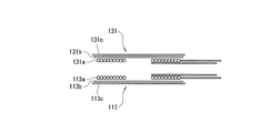
送電コイル113は、図2示すように、平面渦巻き型コイル113aと、磁性シート113bと、金属シート113cとからなる。そして、図3に示すように、平面渦巻き型コイル113aの外面側に、その外面側全体を覆うように、磁性シート113bと金属シート113cとが重ねた状態で設けられている。
Next, specific structures of the
As shown in FIG. 2, the
従って、送電コイル113の構成要素は、図3に示すように、平面渦巻き型コイル113a、磁性シート113b、および金属シート113cの順序で大きくなるように構成され、これらは接着剤などの適宜手段で一体に密着、または固定されている。
また、受電コイル131は、図2に示すように、平面渦巻き型コイル131aと、磁性シート131bと、金属シート131cとからなる。そして、図3に示すように、平面渦巻き型コイル131aの外面側に、その外面側全体を覆うように、磁性シート131bと金属シート131cとが重ねた状態で設けられている。
Therefore, as shown in FIG. 3, the constituent elements of the
Further, as shown in FIG. 2, the
従って、受電コイル131の構成要素は、図3に示すように、平面渦巻き型コイル131a、磁性シート131b、および金属シート131cの順序で大きくなるように構成され、これらは接着剤などの適宜手段で一体に密着または固定されている。
さらに、送電コイル113側の平面渦巻き型コイル113aと、受電コイル131側の平面渦巻き型コイル131aとは、使用時には、図3に示すようにその内面側同士が対向して変圧器を形成するようになっている。このため、使用時には、磁性シート113b、131bは、平面渦巻き型コイル113a、131aが発生する磁界による不要輻射を抑制でき、金属シート113c、131cは、平面渦巻き型コイル113a、131aが発生する電界による不要輻射を抑制できるようになっている。
Therefore, as shown in FIG. 3, the constituent elements of the
Further, the planar
ここで、平面渦巻き型コイル113a,131aは、単線または撚り線のような絶縁された電線からなり、その電線を図2および図3に示すように同一平面内で渦巻き状に巻いたものである。
また、磁性シート113b,131bは、板状またはシート状の磁性材料からなり、けい素鋼板、アモルファス金属の磁性シートなどが使用される。
Here, the
The
さらに、金属シート113c,131cは、板状またはシート状の金属材料からなり、アルミニウムなどが使用される。
次に、図1〜図3に示すような構成からなる送電装置11と受電装置13とを、充電器のケースと携帯電話のケースにそれぞれ組み込んだ場合の具体例について、図4を参照して説明する。
Furthermore, the
Next, a specific example in which the
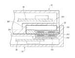
図1に示す送電装置11を構成する各要素は、図4に示す充電器のケース21内に組み込まれ、図1に示す受電装置13を構成する各要素は、図4に示す携帯電話のケース31内に組み込まれている。
充電器のケース21は、図4に示すように、その上部側に、携帯電話の充電時に携帯電話のケース31が収容される携帯電話収容部211を備えている。また、充電器のケース21は、その携帯電話収容部211の下部側に送電コイル収納部212を備え、その送電コイル収納部212内に、図3に示す送電コイル113が例えば密封された状態で収納されている。さらに、充電器のケース21内には、送電装置11のAC/DCコンバータ111や送電回路112などの構成部品を搭載した回路基板22が収容されている。
Each element constituting the
As shown in FIG. 4, the
携帯電話のケース31は、図4に示すように、その下部側に、図1に示す受電装置13をモジュール化した受電装置モジュール32を収容する収容部311と、その受電装置モジュール32の交換の際にその収容部311の開閉を行う蓋312と、を備えている。
ここで、受電装置モジュール32は、上記のように、受電装置13を構成する、受電コイル131、受電回路132、充放電制御回路133、および2次電池134を、一体に1つの容器に収容し、または熱硬化性の合成樹脂などを用いて一体にモジュール化したものである。
As shown in FIG. 4, the
Here, as described above, the power
図4に示す受電装置モジュール32は、同図に示すように、例えば薄型の直方形のケース321内に受電回路132、充放電制御回路133、および2次電池134が収納され、かつそのケース321の下面に受電コイル131がケース321に一体に取り付けられている。
また、携帯電話のケース31内には、携帯電話本体12を構成する各種の電子回路の構成部品を搭載した回路基板33が収容されている。
As shown in FIG. 4, the power
Further, a
次に、このような構成からなる第1実施形態の動作例について、図1および図3を参照して説明する。
受電装置13の2次電池134を、送電装置11を用いて充電する場合について説明する。この場合には、受電装置13の受電コイル131を送電装置11の送電コイル113に接近させて、両コイル131、113を電磁結合する状態にさせる。このときには、送電コイル113と受電コイル131とは、例えば図3または図4に示す状態になる。
Next, an operation example of the first embodiment having such a configuration will be described with reference to FIGS.
A case where the
このように、送電コイル113と受電コイル131が電磁結合されると、受電装置13の2次電池134は、送電装置11による充電が開始される。この充電時には、受電回路132により2次電池134の充電が行われる。
この充電時には、送電コイル113と受電コイル131には磁界や電界が発生し、その不要輻射がある。しかし、図3に示すように、磁性シート113b、131bは、平面渦巻き型コイル113a、131aが発生する磁界による不要輻射を抑制し、金属シート113c、131cは、平面渦巻き型コイル113a、131aが発生する電界による不要輻射を抑制する。
Thus, when the
During this charging, a magnetic field or an electric field is generated in the
充放電制御回路133は、2次電池134の充電状態を監視し、その充電が終了すると、受電回路132による2次電池134の充電を停止させる。
このようにして、2次電池134に充電が終了した場合には、受電装置13の受電コイル131を送電装置11の送電コイル113から離し、これにより、携帯電話本体12は、その充電された2次電池134を電源として使用できる。
The charge /
In this way, when charging of the
以上説明したように、この第1実施形態では、非接触電力伝送に使用される送電コイル113および受電コイル131が平面コイルからなり、使用の際には、それらは変圧器を形成するが、両コイルからの磁界や電界による不要輻射を抑制でき、かつ効率的な電力伝送ができる。
As described above, in the first embodiment, the
(第2実施形態)
本発明の非接触電力伝送装置の第2実施形態の構成について、図5を参照しながら説明する。
(Second Embodiment)
The configuration of the second embodiment of the non-contact power transmission apparatus of the present invention will be described with reference to FIG.
この第2実施形態に係る非接触電力伝送装置は、例えば携帯電話に適用したものであり、図5に示すように、充電器として機能する送電装置11と、携帯電話本体12の電源となる2次電池を含む受電装置13と、充電器として機能するとともに携帯電話本体15の電源となる2次電池を含む送電・受電兼用装置14とを備えている。
そして、送電装置11は、送電・受電兼用装置14または受電装置13と電磁的に結合することにより非接触電力伝送装置をそれぞれ形成し、送電・受電兼用装置14と結合した場合にはそれに含まれる2電池を充電でき、受電装置13と結合した場合にはそれに含まれる2次電池を充電できるようになっている。また、送電・受電兼用装置14は、受電装置13と電磁的に結合することにより非接触電力伝送装置を形成し、このときには受電装置13に含まれる2電池を充電できるようになっている。
The non-contact power transmission apparatus according to the second embodiment is applied to, for example, a cellular phone. As shown in FIG. 5, the
The
次に、この第2実施形態の各部の具体的な構成について、図5を参照して説明する。
送電装置11および受電装置13は、図1に示す送電装置11および受電装置13と同様に構成されるので、同一の構成要素には同一符号を付して、ここではその構成の説明は省略する。
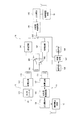
送電・受電兼用装置14は、図5に示すように、送電回路141と、受電回路142と、2次電池143と、充放電制御回路144と、送電・受電コイル145と、切り換えスイッチSW1〜SW3と、設定器146と、制御回路147と、表示器148とを備えている。
Next, a specific configuration of each part of the second embodiment will be described with reference to FIG.
Since the
As shown in FIG. 5, the power transmission /
この送電・受電兼用装置14は、構成要素である送電回路141、受電回路142、2次電池143、充放電制御回路144、送電・受電コイル145、切り換えスイッチSW1〜SW3、設定器146、制御回路147、および表示器148のうち、設定器146および表示器148を除く他の各構成要素を、一体に1つの容器に収容させたり、または熱硬化性の合成樹脂などを用いて一体にモジュール化(固形化)させ、送電・受電兼用装置モジュールとして形成するようにした。
This power transmission / reception combined
ここで、その送電・受電兼用装置モジュールは、図1に示す受電装置13をモジュール化した受電装置モジュールと基本的に同様のものであり、例えば図4に示す受電装置モジュール32と同様に形成される。
送電回路141は、動作時に、2次電池143から供給される直流電圧を使用して所定の周波数の交流電圧を生成し、この生成した交流電圧を送電・受電コイル145に供給する回路である。受電回路142は、送電・受電コイル145が送電装置11の送電コイル113と電磁結合して送電装置11から電力が送電される場合に、送電・受電コイル145に誘起される交流電圧を整流して直流電圧を生成する回路、すなわち交流−直流変換回路である。受電回路142で生成される直流電圧は、充放電制御回路144を介して2次電池143に供給され、2次電池143を充電するようになっている。
Here, the power transmission / reception combined use device module is basically the same as the power reception device module obtained by modularizing the
The
2次電池143は、例えばリチウムイオン電池のように、放電後に充電により繰り返して使用できる電池である。充放電制御回路144は、受電回路142により2次電池143を充電する場合にはその充電の制御(監視)を行い、2次電池143で送電回路141や負荷である携帯電話本体15を動作させる場合には放電の制御(監視)を行う回路である。
The
送電・受電コイル145は、送電装置11の送電コイル113と接近させて使用する場合には、その両コイル145、113は、電磁結合して両者の間で変圧器を形成するようになっている。また、送電・受電コイル145は、受電装置13の受電コイル131と接近させて使用する場合には、その両コイル145、131は、電磁結合して両者の間で変圧器を形成するようになっている。すなわち、送電コイル113、送電・受電コイル145、および受電コイル131は、相互に電磁結合でき、かつ相互に分離できるようになっている。
When the power transmission /
切り換えスイッチSW1,SW2は、送電・受電コイル145と、送電回路141または受電回路142との選択的な接続を行うものである。また、切り換えスイッチSW3は、2次電池143と、送電回路141または受電回路142との選択的な接続を行うものである。これらの切り換えスイッチSW1〜SW3の各接点は、通常は、例えば図示のように受電回路142側に接続されている。
The change-over switches SW1 and SW2 selectively connect the power transmission /
設定器146は、使用者が、送電回路141または受電回路142の使用を選択的に設定するものであり、その設定データが制御回路147に入力されるようになっている。制御回路147は、その設定器146からの設定データに従って、その動作状態を表示器148を表示させるとともに、切り換えスイッチSW1〜SW3の接点の切り換えを制御する回路である。表示器148は、液晶表示器などからなり、上記のように所定の情報が表示されるようになっている。
The
次に、図5に示す送電コイル113、受電コイル131、および送電・受電コイル145の具体的な構成について、図3を参照して説明する。
図5に示す送電コイル113および受電コイル131は、図3に示す第1実施形態の送電コイル113および受電コイル131と同様に構成される。また、図5に示す送電・受電コイル145は、例えば図3に示す送電コイル113または受電コイル131と同様に構成される。
Next, specific configurations of the
The
このような構成により、図5に示す送電コイル113、送電・受電コイル145、および受電コイル131は、使用時に、そのうちの2つのコイルが相互に電磁結合して変圧器を形成し、その際に各コイルで生成される電界や磁界による不要輻射を抑制して効率的な電力伝送ができる。
次に、このような構成からなる第2実施形態の動作例について、図5を参照して説明する。
With this configuration, the
Next, an operation example of the second embodiment having such a configuration will be described with reference to FIG.
ここで、第2実施形態では、第1実施形態の場合と同様に、受電装置13の2次電池134を送電装置11で充電する場合があるが、この場合はすでに説明済みであるので、以下では他の場合の動作について説明する。
まず、携帯電話本体15に搭載される送電・受電兼用装置14の2次電池143を、送電装置11を用いて充電する場合について説明する。この場合には、送電・受電兼用装置14の送電・受電コイル145を送電装置11の送電コイル113に接近させて、両コイル145、113が電磁結合する状態にさせる。
Here, in the second embodiment, as in the case of the first embodiment, the
First, a case where the
この状態で、設定器146により、送電装置11を用いて2次電池143の充電を行う旨の設定を行うと、その設定データが制御回路147に入力される。制御回路147は、その設定データに従い、その旨の表示を表示器148に表示させるとともに、切り換えスイッチSW1〜SW3の接点を、図5に示す位置、すなわち、受電回路142側に接続させる。
In this state, when the
この結果、送電・受電兼用装置14の2次電池143は、送電装置11による充電が開始される。この充電時には、受電回路142により2次電池143の充電が行われる。
また、この充電時には、送電コイル113と送電・受電コイル145により磁界や電界が生成され、その不要輻射がある。しかし、このときには、送電コイル113と送電・受電コイル145とは、上記のように図3に示す送電コイル113および受電コイル131と同様に構成される。このため、送電コイル113と送電・受電コイル145は、図3に示す送電コイル113および受電コイル131と同様に、コイルが発生する磁界や電界による不要輻射を抑制できる。
As a result, the
At the time of charging, a magnetic field or an electric field is generated by the
充放電制御回路144は、2次電池143の充電状態を監視し、その充電が終了すると、受電回路142による2次電池143の充電を停止させる。
次に、携帯電話本体12に搭載される受電装置13の2次電池134が使用不能となり、その2次電池134の充電を、携帯電話本体15に搭載される送電・受電兼用装置14を用いて充電する場合について説明する。
The charge /
Next, the
この場合には、受電装置13の受電コイル131を送電・受電兼用装置14の送電・受電コイル145に接近させて、両コイル131、145が電磁結合する状態にさせる。この状態で、送電・受電兼用装置14により2次電池134を充電させる旨の設定を設定器146で行うと、その設定データが制御回路147に入力される。制御回路147は、その設定データに従い、その旨の表示を表示器148に表示させるとともに、切り換えスイッチSW1〜SW3の接点を、図に示す位置とは反対の位置、すなわち、送電回路141側に切り換える。
In this case, the
この結果、受電装置13の2次電池134は、送電・受電兼用装置14による充電が開始される。この充電時には、受電回路132により2次電池134の充電が行われる。
また、この充電時には、受電コイル131と送電・受電コイル145により磁界や電界が生成され、その不要輻射がある。しかし、このときには、受電コイル131と送電・受電コイル145とは、上記のように図3に示す送電コイル113および受電コイル131と同様に構成される。このため、、受電コイル131と送電・受電コイル145は、図3に示す送電コイル113および受電コイル131と同様に、コイルが発生する磁界や電界による不要輻射を抑制できる。
As a result, the
At the time of charging, a magnetic field or an electric field is generated by the
充放電制御回路133は、2次電池134の充電状態を監視し、その充電が終了すると、受電回路132による2次電池134の充電を停止させる。
以上説明したように、この第2実施形態では、非接触電力伝送に使用される送電コイル113、送電・受電コイル145、および受電コイル131が平面コイルからり、使用の際には、そのうちの2つのコイルにより変圧器が形成されるが、その変圧器を形成するコイルからの磁界や電界による不要輻射を抑制でき、かつ、電力伝送の効率化を図ることができる。
The charge /
As described above, in the second embodiment, the
また、この第2実施形態では、充電器として機能するとともに2次電池143を含む送電・受電兼用装置14を携帯電話本体15に搭載し、2次電池134を含む受電装置13を携帯電話本体12に搭載するようした。
このため、第2実施形態によれば、受電装置13を搭載する携帯電話が使用不能になっても、送電・受電兼用装置14を搭載する携帯電話を使用して受電装置13の2次電池134を充電できるので、非常に便宜である。
In the second embodiment, the power transmission /
For this reason, according to the second embodiment, even if the mobile phone equipped with the
さらに、第2実施形態の送電・受電兼用装置14では、2次電池として使用する場合または充電器として使用する場合に、その使用を任意に設定できる上に、その設定状態を使用者が表示器により容易に認識できるので、その設定ミスによる誤動作を防止できる。
(その他の実施形態)
第1実施形態では、図2および図3に示すように、送電コイル113は、平面渦巻き型コイル113a、磁性シート113b、および金属シート113cから構成し、受電コイル131は、平面渦巻き型コイル131a、磁性シート131b、および金属シート131cから構成するようにした。しかし、送電コイル113および受電コイル131は、金属シート113c、131cをそれぞれ省略するようにしても良い。
Furthermore, in the power transmission /
(Other embodiments)
In the first embodiment, as shown in FIGS. 2 and 3, the
この点の構成については、第2実施形態における送電コイル113、送電・受電コイル145、および受電コイル131の各構成についても同様である。
また、第1実施形態では、受電装置13は、構成要素である受電コイル131、受電回路132、充放電制御回路133、および2次電池134を一体化し、受電装置モジュールとして形成するようにしたが、この一体化は少なくとも受電コイル131と2次電池134であれば良い。
About the structure of this point, it is the same also about each structure of the
In the first embodiment, the
さらに、第2実施形態では、送電・受電兼用装置14は、構成要素である送電回路141、受電回路142、2次電池143、充放電制御回路144、送電・受電コイル145、切り換えスイッチSW1〜SW3、設定器146、制御回路147、および表示器148のうち、設定器146および表示器148を除く他の各構成要素を一体化し、送電・受電兼用装置モジュールとして形成するようにした。しかし、この一体化は少なくとも送電・受電コイル131と2次電池143であれば良い。
Furthermore, in 2nd Embodiment, the power transmission / reception combined
また、第1実施形態および第2実施形態では、携帯電話に適用した場合について説明したが、これに代えて携帯用のコンピュータなどの携帯端末、またはビデオカメラのような携帯機器に適用できる。 In the first embodiment and the second embodiment, the case where the present invention is applied to a mobile phone has been described. However, the present invention can be applied to a mobile terminal such as a portable computer or a video camera instead.
11・・・送電装置、12、15・・・携帯電話本体、13・・・受電装置、14・・・送電・受電兼用装置、32・・・受電装置モジュール、113・・・送電コイル、113a、131a・・・平面渦巻き型コイル、113b、131b・・・磁性シート、113c、131c・・・金属シート、112、141・・・送電回路、131・・・受電コイル、132、142・・・受電回路、134、143・・・2次電池、145・・・送電・受電コイル。
DESCRIPTION OF
Claims (7)
前記第1コイルおよび前記第2コイルは、各々の平面が対向するようになっている第1平面コイルおよび第2平面コイルからなり、
前記第1平面コイルおよび前記第2平面コイルは、その両者が対向する面の反対側の面に、磁性シートをそれぞれ設け、
前記第1平面コイルおよび前記第2平面コイルに設けた各磁性シートの外側面に、さらに、金属シートをそれぞれ重ねて設けたことを特徴とする非接触電力伝送装置。 A power transmission device having a first coil for power transmission, and a power reception device having a second coil for power reception,
Before Symbol first coil and said second coil comprises a first planar coil and the second planar coil, each of the planes is adapted to face,
Before Symbol first planar coil and said second planar coil, the surface opposite to the surface on which both faces, provided the magnetic sheet, respectively,
A non-contact power transmission device , wherein a metal sheet is further provided on the outer surface of each magnetic sheet provided on the first planar coil and the second planar coil .
前記送電装置は、The power transmission device is:
前記第1コイルが前記第2コイルまたは前記第3コイルと電磁結合するときに、前記第1コイルに供給する交流を生成する送電手段を有し、When the first coil is electromagnetically coupled to the second coil or the third coil, power transmission means for generating an alternating current to be supplied to the first coil,
前記送電・受電兼用装置は、The power transmission / reception device is:
前記受電装置の前記第2の2次電池の使用ができなくなって前記第2コイルが前記第3コイルと電磁結合するときに、前記第1の2次電池を電源として用いて前記第2コイルに供給する交流を生成する送電手段と、When the second secondary battery of the power receiving device cannot be used and the second coil is electromagnetically coupled to the third coil, the first secondary battery is used as a power source for the second coil. Power transmission means for generating alternating current to be supplied;
前記第2コイルが前記第1コイルと電磁結合するときに、前記第2コイルに誘起される交流を直流に変換し、この変換された直流により前記第1の2次電池の充電を行う受電手段とを有し、When the second coil is electromagnetically coupled to the first coil, power receiving means for converting alternating current induced in the second coil into direct current and charging the first secondary battery with the converted direct current And
前記受電装置は、The power receiving device is:
前記第3コイルが前記第1コイルまたは前記第2コイルと電磁結合するときに、前記第3コイルに誘起される交流を直流に変換し、この変換された直流により前記第2の2次電池の充電を行う受電手段を有し、When the third coil is electromagnetically coupled to the first coil or the second coil, the alternating current induced in the third coil is converted into direct current, and the converted direct current causes the second secondary battery to Having power receiving means for charging,
前記第1コイル、前記第2コイル、および前記第3コイルは、各々の平面が相互に対向するようになっている第1平面コイル、第2平面コイル、および第3平面コイルからなり、The first coil, the second coil, and the third coil are composed of a first planar coil, a second planar coil, and a third planar coil in which the respective planes are opposed to each other,
前記第1平面コイル、第2平面コイル、および前記第3平面コイルは、対向する面の反対側の面に磁性シートをそれぞれ設け、The first planar coil, the second planar coil, and the third planar coil are each provided with a magnetic sheet on the surface opposite to the facing surface,
前記第1平面コイル、前記第2平面コイル、および前記第3平面コイルに設けた各磁性シートの外側面に、さらに、金属シートをそれぞれ重ねて設けたことを特徴とする非接触電力伝送装置。A contactless power transmission device, wherein a metal sheet is further provided on the outer surface of each magnetic sheet provided in the first planar coil, the second planar coil, and the third planar coil.
かつ、前記受電装置を構成する前記第3コイル、前記受電手段、および前記第2の2次電池のうち、少なくとも前記第3コイルと前記第2の2次電池を一体化したことを特徴とする請求項4に記載の非接触電力伝送装置。In addition, at least the third coil and the second secondary battery among the third coil, the power receiving unit, and the second secondary battery constituting the power receiving device are integrated. The non-contact power transmission device according to claim 4.
かつ、前記受電装置を構成する前記第3コイル、前記受電手段、および前記第2の2次電池のうち、少なくとも前記第3コイルと前記第2の2次電池は、所定のケース内に収容し又は固形化するようにしたことを特徴とする請求項4に記載の非接触電力伝送装置。 At least the second coil and the first secondary battery among the second coil, the power transmission unit, the power reception unit, and the first secondary battery constituting the power transmission / reception combined device are predetermined To be housed or solidified in the case,
And among the said 3rd coil which comprises the said power receiving apparatus, the said power receiving means, and the said 2nd secondary battery, at least a said 3rd coil and a said 2nd secondary battery are accommodated in a predetermined case. The contactless power transmission device according to claim 4, wherein the contactless power transmission device is solidified .
Priority Applications (1)
| Application Number | Priority Date | Filing Date | Title |
|---|---|---|---|
| JP2004219904A JP4852829B2 (en) | 2004-07-28 | 2004-07-28 | Non-contact power transmission device |
Applications Claiming Priority (1)
| Application Number | Priority Date | Filing Date | Title |
|---|---|---|---|
| JP2004219904A JP4852829B2 (en) | 2004-07-28 | 2004-07-28 | Non-contact power transmission device |
Publications (2)
| Publication Number | Publication Date |
|---|---|
| JP2006042519A JP2006042519A (en) | 2006-02-09 |
| JP4852829B2 true JP4852829B2 (en) | 2012-01-11 |
Family
ID=35906887
Family Applications (1)
| Application Number | Title | Priority Date | Filing Date |
|---|---|---|---|
| JP2004219904A Active JP4852829B2 (en) | 2004-07-28 | 2004-07-28 | Non-contact power transmission device |
Country Status (1)
| Country | Link |
|---|---|
| JP (1) | JP4852829B2 (en) |
Cited By (2)
| Publication number | Priority date | Publication date | Assignee | Title |
|---|---|---|---|---|
| CN103312047A (en) * | 2013-05-09 | 2013-09-18 | 北京航空航天大学 | High-efficiency large-power electric energy transmitting and receiving device of contactless charging system |
| US9709835B2 (en) | 2012-11-15 | 2017-07-18 | Sharp Kabushiki Kaisha | Liquid crystal module and electronic device |
Families Citing this family (84)
| Publication number | Priority date | Publication date | Assignee | Title |
|---|---|---|---|---|
| US8447234B2 (en) | 2006-01-18 | 2013-05-21 | Qualcomm Incorporated | Method and system for powering an electronic device via a wireless link |
| US9130602B2 (en) | 2006-01-18 | 2015-09-08 | Qualcomm Incorporated | Method and apparatus for delivering energy to an electrical or electronic device via a wireless link |
| JP5231993B2 (en) * | 2006-03-24 | 2013-07-10 | 株式会社東芝 | Power receiving device for non-contact charger |
| JP5231998B2 (en) * | 2006-03-24 | 2013-07-10 | 株式会社東芝 | Power receiving device |
| JP5300187B2 (en) * | 2006-09-07 | 2013-09-25 | 三洋電機株式会社 | Pack battery charged by magnetic induction |
| JP4960710B2 (en) | 2007-01-09 | 2012-06-27 | ソニーモバイルコミュニケーションズ株式会社 | Non-contact power transmission coil, portable terminal, terminal charging device, planar coil magnetic layer forming apparatus and magnetic layer forming method |
| JP4947637B2 (en) | 2007-01-09 | 2012-06-06 | ソニーモバイルコミュニケーションズ株式会社 | Non-contact power transmission coil, portable terminal and terminal charging device |
| KR101121481B1 (en) * | 2007-02-20 | 2012-02-28 | 세이코 엡슨 가부시키가이샤 | Coil unit, manufacturing method thereof, and electronic machine |
| KR101122983B1 (en) * | 2007-02-20 | 2012-03-15 | 세이코 엡슨 가부시키가이샤 | Coil unit and electronic instrument |
| US9774086B2 (en) | 2007-03-02 | 2017-09-26 | Qualcomm Incorporated | Wireless power apparatus and methods |
| JP4722066B2 (en) * | 2007-03-02 | 2011-07-13 | 株式会社オリンピア | Game machine |
| CA2941147A1 (en) * | 2007-05-10 | 2008-11-20 | Auckland Uniservices Limited | Multi power sourced electric vehicle |
| US9466419B2 (en) | 2007-05-10 | 2016-10-11 | Auckland Uniservices Limited | Apparatus and system for charging a battery |
| JP5266665B2 (en) * | 2007-05-16 | 2013-08-21 | セイコーエプソン株式会社 | Electronic equipment, charger and charging system |
| JP5121307B2 (en) * | 2007-05-28 | 2013-01-16 | ソニーモバイルコミュニケーションズ株式会社 | Non-contact power transmission coil unit, portable terminal, power transmission device, and non-contact power transmission system |
| US9124120B2 (en) | 2007-06-11 | 2015-09-01 | Qualcomm Incorporated | Wireless power system and proximity effects |
| JP4420073B2 (en) | 2007-07-11 | 2010-02-24 | セイコーエプソン株式会社 | Coil unit and electronic equipment |
| JP4605192B2 (en) | 2007-07-20 | 2011-01-05 | セイコーエプソン株式会社 | Coil unit and electronic equipment |
| CN103187629B (en) | 2007-08-09 | 2016-08-24 | 高通股份有限公司 | Increase the Q factor of resonator |
| JP2010539821A (en) | 2007-09-13 | 2010-12-16 | クゥアルコム・インコーポレイテッド | Maximizing the power generated from wireless power magnetic resonators |
| EP2201641A1 (en) | 2007-09-17 | 2010-06-30 | Qualcomm Incorporated | Transmitters and receivers for wireless energy transfer |
| JP5362733B2 (en) | 2007-10-11 | 2013-12-11 | クゥアルコム・インコーポレイテッド | Wireless power transfer using a magneto-mechanical system |
| JP5160858B2 (en) * | 2007-10-25 | 2013-03-13 | メレアグロス株式会社 | A coil of a power transmission device, a power transmission device, a power transmission device of the power transmission device, and a power reception device of the power transmission device. |
| US8629576B2 (en) | 2008-03-28 | 2014-01-14 | Qualcomm Incorporated | Tuning and gain control in electro-magnetic power systems |
| JP4752879B2 (en) | 2008-07-04 | 2011-08-17 | パナソニック電工株式会社 | Planar coil |
| JP5223509B2 (en) * | 2008-07-09 | 2013-06-26 | 株式会社村田製作所 | Power conversion transmission device and non-contact type charged device |
| US8278784B2 (en) * | 2008-07-28 | 2012-10-02 | Qualcomm Incorporated | Wireless power transmission for electronic devices |
| JP4815485B2 (en) * | 2008-11-14 | 2011-11-16 | 東光株式会社 | Non-contact power transmission device |
| JP5689587B2 (en) * | 2009-03-31 | 2015-03-25 | 富士通株式会社 | Power transmission equipment |
| EP2433347B1 (en) | 2009-05-20 | 2013-10-23 | Koninklijke Philips N.V. | Electronic device having an inductive receiver coil with ultra-thin shielding layer and method |
| JP2011010435A (en) * | 2009-06-25 | 2011-01-13 | Fujitsu Ten Ltd | Contactless power supply system and contactless power supply unit |
| JP2013502193A (en) | 2009-08-07 | 2013-01-17 | オークランド ユニサービシズ リミテッド | Inductive power transfer system |
| KR101806955B1 (en) * | 2010-05-19 | 2017-12-11 | 삼성전자주식회사 | Apparatus for contactless charge of mobile terminal |
| US9620281B2 (en) * | 2010-08-06 | 2017-04-11 | Auckland Uniservices Limited | Inductive power receiver apparatus |
| JP5649370B2 (en) * | 2010-08-25 | 2015-01-07 | Necトーキン株式会社 | Non-contact power transmission system |
| CN102403803A (en) * | 2010-09-08 | 2012-04-04 | 朱斯忠 | Unidirectional-transmission wireless power supply antenna module |
| KR101896631B1 (en) | 2010-12-01 | 2018-09-07 | 파나소닉 주식회사 | Non-contact Charging Module and Non-contact Charging Instrument |
| WO2012101729A1 (en) | 2011-01-26 | 2012-08-02 | パナソニック株式会社 | Non-contact charging module and non-contact charging instrument |
| WO2012101730A1 (en) | 2011-01-26 | 2012-08-02 | パナソニック株式会社 | Contactless charging module and receiving-side and transmission-side contactless charger using same |
| EP2546844A4 (en) | 2011-01-26 | 2013-04-03 | Panasonic Corp | Contactless charging module and receiving-side and transmission-side contactless charger using same |
| WO2012104954A1 (en) | 2011-02-01 | 2012-08-09 | パナソニック株式会社 | Non-contact charging module and non-contact charger |
| EP2669913B1 (en) | 2011-03-09 | 2016-05-25 | Panasonic Intellectual Property Management Co., Ltd. | Contactless charging module, contactless charging device, and method of manufacturing contactless charging module |
| DE102011104878A1 (en) * | 2011-06-07 | 2012-12-13 | Hella Kgaa Hueck & Co. | antenna device |
| WO2012172812A1 (en) | 2011-06-14 | 2012-12-20 | パナソニック株式会社 | Communication apparatus |
| JP4900528B1 (en) * | 2011-09-08 | 2012-03-21 | パナソニック株式会社 | Non-contact charging module and non-contact charging device using the same |
| JP5845407B2 (en) * | 2011-09-22 | 2016-01-20 | パナソニックIpマネジメント株式会社 | Receiving side non-contact charging module and receiving side non-contact charging device |
| WO2013065245A1 (en) | 2011-11-02 | 2013-05-10 | パナソニック株式会社 | Non-contact wireless communication coil, transmission coil, and portable wireless terminal |
| US10204734B2 (en) | 2011-11-02 | 2019-02-12 | Panasonic Corporation | Electronic device including non-contact charging module and near field communication antenna |
| JP5955006B2 (en) * | 2012-02-01 | 2016-07-20 | キヤノン株式会社 | Electronics |
| JP2013169122A (en) | 2012-02-17 | 2013-08-29 | Panasonic Corp | Non-contact charge module and portable terminal having the same |
| CN102611209A (en) * | 2012-03-21 | 2012-07-25 | 哈尔滨工业大学 | Magnetic coupling resonance type wireless energy transmission device based on panel magnetic core |
| CN107275763B (en) | 2012-03-23 | 2020-07-28 | Lg 伊诺特有限公司 | Antenna assembly |
| TWI459418B (en) * | 2012-03-23 | 2014-11-01 | Lg伊諾特股份有限公司 | Wireless power receiver and portable terminal comprising the same |
| JP2013214614A (en) * | 2012-04-02 | 2013-10-17 | Panasonic Corp | Coil unit and power transmission device having coil unit |
| JP5045858B1 (en) * | 2012-04-12 | 2012-10-10 | パナソニック株式会社 | Non-contact charging module manufacturing method and non-contact charging module |
| GB2502084A (en) * | 2012-05-14 | 2013-11-20 | Bombardier Transp Gmbh | Arrangement for providing vehicles with energy comprising magnetisable material |
| JP6112383B2 (en) | 2012-06-28 | 2017-04-12 | パナソニックIpマネジメント株式会社 | Mobile device |
| JP6008237B2 (en) | 2012-06-28 | 2016-10-19 | パナソニックIpマネジメント株式会社 | Mobile device |
| JP2014197937A (en) * | 2013-03-29 | 2014-10-16 | 沖電気工業株式会社 | Non-contact power transmission device, non-contact power transmission system, and automatic transaction device |
| JP5747182B2 (en) * | 2013-03-29 | 2015-07-08 | パナソニックIpマネジメント株式会社 | Communication device |
| CN103248094A (en) * | 2013-05-08 | 2013-08-14 | 上海安费诺永亿通讯电子有限公司 | Enhanced wireless charging system |
| WO2014185490A1 (en) * | 2013-05-15 | 2014-11-20 | 日本電気株式会社 | Power transfer system, power transmitting device, power receiving device, and power transfer method |
| JP2015012656A (en) | 2013-06-27 | 2015-01-19 | Tdk株式会社 | Wireless power transmission device |
| US9601267B2 (en) | 2013-07-03 | 2017-03-21 | Qualcomm Incorporated | Wireless power transmitter with a plurality of magnetic oscillators |
| US10396596B2 (en) | 2013-11-13 | 2019-08-27 | Apple Inc. | Transmitter for inductive power transfer systems |
| CN104659925A (en) * | 2013-11-20 | 2015-05-27 | 中兴通讯股份有限公司 | Wireless power transceiving method and device |
| JP2015141687A (en) * | 2014-01-30 | 2015-08-03 | Necトーキン株式会社 | Wireless charging antenna, input device, holder, detecting device, and coordinate input device |
| WO2015157309A1 (en) | 2014-04-07 | 2015-10-15 | Zodiac Seats Us Llc | Inductive power transmission in aircraft seats |
| WO2015178780A1 (en) | 2014-05-19 | 2015-11-26 | Powerbyproxi Limited | Magnetically permeable core and inductive power transfer coil arrangement |
| US10325719B2 (en) | 2014-05-19 | 2019-06-18 | Apple Inc. | Magnetically permeable core and an inductive power transfer coil arrangement |
| CA2957903A1 (en) | 2014-08-12 | 2016-02-18 | Powerbyproxi Limited | System and method for power transfer |
| RU2623095C2 (en) * | 2014-12-16 | 2017-06-22 | Самсунг Электроникс Ко., Лтд. | Wireless charging system and its application for charging mobile and portable devices |
| WO2017022054A1 (en) * | 2015-08-03 | 2017-02-09 | 三菱電機エンジニアリング株式会社 | Power transmission device and antenna |
| JP6622558B2 (en) | 2015-10-23 | 2019-12-18 | キヤノン株式会社 | Wireless power transmission system and power transmission device |
| WO2017204663A1 (en) | 2016-05-25 | 2017-11-30 | Powerbyproxi Limited | A coil arrangement |
| WO2017209630A1 (en) | 2016-06-01 | 2017-12-07 | Powerbyproxi Limited | A powered joint with wireless transfer |
| CN110192324A (en) * | 2016-09-16 | 2019-08-30 | Tdk电子股份有限公司 | Wireless power transmitter, Wireless power transmission system and the method for driving Wireless power transmission system |
| US11038376B2 (en) | 2016-09-16 | 2021-06-15 | Tdk Electronics Ag | Wireless power transmitter, wireless power transmission system and method for driving a wireless power transmission system |
| CN206834025U (en) | 2016-11-18 | 2018-01-02 | 鲍尔拜普罗克西有限公司 | Induction type power transmission line coil assembly |
| US10978911B2 (en) | 2016-12-19 | 2021-04-13 | Apple Inc. | Inductive power transfer system |
| WO2018222758A1 (en) | 2017-05-30 | 2018-12-06 | Wireless Advanced Vehicle Electrification, Inc. | Single feed multi-pad wireless charging |
| US10826329B2 (en) | 2017-12-22 | 2020-11-03 | Wireless Advanced Vehicle Electrification, Inc. | Wireless power transfer pad with multiple windings and magnetic pathway between windings |
| US11462943B2 (en) | 2018-01-30 | 2022-10-04 | Wireless Advanced Vehicle Electrification, Llc | DC link charging of capacitor in a wireless power transfer pad |
| US10593468B2 (en) | 2018-04-05 | 2020-03-17 | Apple Inc. | Inductive power transfer assembly |
Family Cites Families (3)
| Publication number | Priority date | Publication date | Assignee | Title |
|---|---|---|---|---|
| JPH11103531A (en) * | 1997-09-29 | 1999-04-13 | Nec Mori Energy Kk | Noncontact charger |
| JP2003037949A (en) * | 2001-07-26 | 2003-02-07 | Matsushita Electric Works Ltd | Non-contact power transmission device |
| JP2004227046A (en) * | 2003-01-20 | 2004-08-12 | Hitachi Ltd | Portable information device |
-
2004
- 2004-07-28 JP JP2004219904A patent/JP4852829B2/en active Active
Cited By (2)
| Publication number | Priority date | Publication date | Assignee | Title |
|---|---|---|---|---|
| US9709835B2 (en) | 2012-11-15 | 2017-07-18 | Sharp Kabushiki Kaisha | Liquid crystal module and electronic device |
| CN103312047A (en) * | 2013-05-09 | 2013-09-18 | 北京航空航天大学 | High-efficiency large-power electric energy transmitting and receiving device of contactless charging system |
Also Published As
| Publication number | Publication date |
|---|---|
| JP2006042519A (en) | 2006-02-09 |
Similar Documents
| Publication | Publication Date | Title |
|---|---|---|
| JP4852829B2 (en) | Non-contact power transmission device | |
| EP1908159B1 (en) | Rechargeable battery circuit and structure for compatibility with a planar inductive charging platform | |
| EP2579427B1 (en) | Power receiver for wireless charging, and portable electronic device having same | |
| EP1368815B1 (en) | Inductive coupling system with capacitive parallel compensation of the mutual self-inductance between the primary and the secondary windings | |
| TW382157B (en) | Power transfer and voltage level conversion for a battery-powered electronic device | |
| JP5118394B2 (en) | Non-contact power transmission equipment | |
| KR101890326B1 (en) | Wireless power transfer module and portable auxiliary battery including the same | |
| KR101795544B1 (en) | bag having battery | |
| JP3996171B2 (en) | Battery pack lid providing non-contact charging interface and mobile phone including the battery pack lid | |
| CN115956747A (en) | Portable terminal casing with built-in battery | |
| EP2278654A1 (en) | Contactless cell apparatus | |
| JP2008210861A (en) | Coil having magnetic shield sheet | |
| JP2006094699A (en) | Inductively charged pad having arrangement indicator | |
| WO2012039245A1 (en) | Coil module for contactless electric power transfer, and battery pack and charging device provided with same | |
| JPH1198706A (en) | Non-contact charger | |
| JPH11103531A (en) | Noncontact charger | |
| JP2010213570A (en) | Structure of portable electronic device for receiving power by radio | |
| JP3907723B2 (en) | Battery pack | |
| JP2007129658A (en) | Portable terminal device and power exchange method | |
| KR101470438B1 (en) | Wireless charging battery case of multiple function | |
| JP2012005185A (en) | Non-contact power transmission and communication system | |
| JP7487237B2 (en) | Portable battery pack for wirelessly charging a wearable device through clothing | |
| CN212010589U (en) | Coil module | |
| JP2012070566A (en) | Non-contact rechargeable type electrical apparatus and charging system for the same | |
| KR20140056606A (en) | Wireless charging battery pack comprising near field communication circuit part and wireless charging circuit part |
Legal Events
| Date | Code | Title | Description |
|---|---|---|---|
| A621 | Written request for application examination |
Free format text: JAPANESE INTERMEDIATE CODE: A621 Effective date: 20070725 |
|
| A977 | Report on retrieval |
Free format text: JAPANESE INTERMEDIATE CODE: A971007 Effective date: 20100301 |
|
| A131 | Notification of reasons for refusal |
Free format text: JAPANESE INTERMEDIATE CODE: A131 Effective date: 20100309 |
|
| A521 | Request for written amendment filed |
Free format text: JAPANESE INTERMEDIATE CODE: A523 Effective date: 20100510 |
|
| A131 | Notification of reasons for refusal |
Free format text: JAPANESE INTERMEDIATE CODE: A131 Effective date: 20110315 |
|
| TRDD | Decision of grant or rejection written | ||
| A01 | Written decision to grant a patent or to grant a registration (utility model) |
Free format text: JAPANESE INTERMEDIATE CODE: A01 Effective date: 20110927 |
|
| A01 | Written decision to grant a patent or to grant a registration (utility model) |
Free format text: JAPANESE INTERMEDIATE CODE: A01 |
|
| A61 | First payment of annual fees (during grant procedure) |
Free format text: JAPANESE INTERMEDIATE CODE: A61 Effective date: 20111010 |
|
| FPAY | Renewal fee payment (event date is renewal date of database) |
Free format text: PAYMENT UNTIL: 20141104 Year of fee payment: 3 |
|
| R150 | Certificate of patent or registration of utility model |
Ref document number: 4852829 Country of ref document: JP Free format text: JAPANESE INTERMEDIATE CODE: R150 Free format text: JAPANESE INTERMEDIATE CODE: R150 |
|
| S531 | Written request for registration of change of domicile |
Free format text: JAPANESE INTERMEDIATE CODE: R313531 |
|
| R350 | Written notification of registration of transfer |
Free format text: JAPANESE INTERMEDIATE CODE: R350 |
|
| R250 | Receipt of annual fees |
Free format text: JAPANESE INTERMEDIATE CODE: R250 |
|
| R250 | Receipt of annual fees |
Free format text: JAPANESE INTERMEDIATE CODE: R250 |
|
| R250 | Receipt of annual fees |
Free format text: JAPANESE INTERMEDIATE CODE: R250 |
|
| R250 | Receipt of annual fees |
Free format text: JAPANESE INTERMEDIATE CODE: R250 |
|
| S111 | Request for change of ownership or part of ownership |
Free format text: JAPANESE INTERMEDIATE CODE: R313113 |
|
| R350 | Written notification of registration of transfer |
Free format text: JAPANESE INTERMEDIATE CODE: R350 |
|
| R250 | Receipt of annual fees |
Free format text: JAPANESE INTERMEDIATE CODE: R250 |