KR20140092378A - System and method for processing samples - Google Patents
System and method for processing samples Download PDFInfo
- Publication number
- KR20140092378A KR20140092378A KR1020147014772A KR20147014772A KR20140092378A KR 20140092378 A KR20140092378 A KR 20140092378A KR 1020147014772 A KR1020147014772 A KR 1020147014772A KR 20147014772 A KR20147014772 A KR 20147014772A KR 20140092378 A KR20140092378 A KR 20140092378A
- Authority
- KR
- South Korea
- Prior art keywords
- sample
- unit
- tube
- centrifuge
- sample container
- Prior art date
Links
- 238000000034 method Methods 0.000 title claims abstract description 155
- 238000012545 processing Methods 0.000 title abstract description 154
- 239000000523 sample Substances 0.000 claims description 1255
- 238000004458 analytical method Methods 0.000 claims description 92
- 239000000872 buffer Substances 0.000 claims description 52
- 238000001514 detection method Methods 0.000 claims description 46
- 238000012546 transfer Methods 0.000 claims description 46
- 238000003860 storage Methods 0.000 claims description 39
- 238000005119 centrifugation Methods 0.000 claims description 37
- 239000007788 liquid Substances 0.000 claims description 37
- 238000009826 distribution Methods 0.000 claims description 32
- 230000005291 magnetic effect Effects 0.000 claims description 27
- 210000002966 serum Anatomy 0.000 claims description 27
- 238000012360 testing method Methods 0.000 claims description 22
- 239000000969 carrier Substances 0.000 claims description 20
- 239000012530 fluid Substances 0.000 claims description 11
- 238000003384 imaging method Methods 0.000 claims description 4
- 239000002594 sorbent Substances 0.000 claims 1
- 230000032258 transport Effects 0.000 description 316
- 239000000047 product Substances 0.000 description 102
- 230000008569 process Effects 0.000 description 70
- 230000006870 function Effects 0.000 description 51
- 238000010586 diagram Methods 0.000 description 46
- 238000011068 loading method Methods 0.000 description 45
- 238000010191 image analysis Methods 0.000 description 26
- 230000033001 locomotion Effects 0.000 description 25
- 230000003287 optical effect Effects 0.000 description 25
- 238000012384 transportation and delivery Methods 0.000 description 23
- 238000012512 characterization method Methods 0.000 description 17
- 239000003550 marker Substances 0.000 description 15
- 230000005855 radiation Effects 0.000 description 15
- 239000004020 conductor Substances 0.000 description 14
- 238000005516 engineering process Methods 0.000 description 14
- 230000000704 physical effect Effects 0.000 description 14
- 230000001133 acceleration Effects 0.000 description 12
- 238000013459 approach Methods 0.000 description 12
- 238000004891 communication Methods 0.000 description 12
- 239000000463 material Substances 0.000 description 12
- 238000005259 measurement Methods 0.000 description 12
- 230000005540 biological transmission Effects 0.000 description 10
- 230000008901 benefit Effects 0.000 description 9
- 238000011143 downstream manufacturing Methods 0.000 description 9
- 230000007246 mechanism Effects 0.000 description 8
- 238000010521 absorption reaction Methods 0.000 description 7
- 230000008859 change Effects 0.000 description 7
- 239000002920 hazardous waste Substances 0.000 description 7
- 238000007726 management method Methods 0.000 description 7
- 239000013610 patient sample Substances 0.000 description 7
- 230000001965 increasing effect Effects 0.000 description 6
- 230000014759 maintenance of location Effects 0.000 description 6
- 239000002245 particle Substances 0.000 description 6
- 230000002265 prevention Effects 0.000 description 6
- 230000009977 dual effect Effects 0.000 description 5
- 230000005672 electromagnetic field Effects 0.000 description 5
- 210000003743 erythrocyte Anatomy 0.000 description 5
- 230000003993 interaction Effects 0.000 description 5
- 238000012423 maintenance Methods 0.000 description 5
- 229920003023 plastic Polymers 0.000 description 5
- 239000004033 plastic Substances 0.000 description 5
- 230000002829 reductive effect Effects 0.000 description 5
- 238000011282 treatment Methods 0.000 description 5
- 239000002699 waste material Substances 0.000 description 5
- 229910000831 Steel Inorganic materials 0.000 description 4
- 210000004369 blood Anatomy 0.000 description 4
- 239000008280 blood Substances 0.000 description 4
- 238000006243 chemical reaction Methods 0.000 description 4
- 230000006835 compression Effects 0.000 description 4
- 238000007906 compression Methods 0.000 description 4
- 238000013016 damping Methods 0.000 description 4
- 238000013461 design Methods 0.000 description 4
- 230000000694 effects Effects 0.000 description 4
- 239000011521 glass Substances 0.000 description 4
- 230000001939 inductive effect Effects 0.000 description 4
- 238000012913 prioritisation Methods 0.000 description 4
- 230000004044 response Effects 0.000 description 4
- 239000010959 steel Substances 0.000 description 4
- 230000000007 visual effect Effects 0.000 description 4
- 239000000853 adhesive Substances 0.000 description 3
- 238000004364 calculation method Methods 0.000 description 3
- 239000000470 constituent Substances 0.000 description 3
- 238000011109 contamination Methods 0.000 description 3
- 238000010438 heat treatment Methods 0.000 description 3
- 230000006698 induction Effects 0.000 description 3
- 238000003780 insertion Methods 0.000 description 3
- 230000037431 insertion Effects 0.000 description 3
- 239000011159 matrix material Substances 0.000 description 3
- 238000002360 preparation method Methods 0.000 description 3
- 238000009987 spinning Methods 0.000 description 3
- 238000011144 upstream manufacturing Methods 0.000 description 3
- 230000009471 action Effects 0.000 description 2
- 230000009056 active transport Effects 0.000 description 2
- 230000032683 aging Effects 0.000 description 2
- 230000002238 attenuated effect Effects 0.000 description 2
- 238000013500 data storage Methods 0.000 description 2
- 230000002950 deficient Effects 0.000 description 2
- 230000001419 dependent effect Effects 0.000 description 2
- 229910003460 diamond Inorganic materials 0.000 description 2
- 239000010432 diamond Substances 0.000 description 2
- 238000006073 displacement reaction Methods 0.000 description 2
- 239000011888 foil Substances 0.000 description 2
- 238000005194 fractionation Methods 0.000 description 2
- 238000005286 illumination Methods 0.000 description 2
- 238000007689 inspection Methods 0.000 description 2
- 230000002452 interceptive effect Effects 0.000 description 2
- 239000002184 metal Substances 0.000 description 2
- 229910052751 metal Inorganic materials 0.000 description 2
- 239000000203 mixture Substances 0.000 description 2
- 238000005457 optimization Methods 0.000 description 2
- 230000010355 oscillation Effects 0.000 description 2
- 230000036961 partial effect Effects 0.000 description 2
- 230000000737 periodic effect Effects 0.000 description 2
- 230000000717 retained effect Effects 0.000 description 2
- 230000001360 synchronised effect Effects 0.000 description 2
- 230000007704 transition Effects 0.000 description 2
- IQVNEKKDSLOHHK-FNCQTZNRSA-N (E,E)-hydramethylnon Chemical compound N1CC(C)(C)CNC1=NN=C(/C=C/C=1C=CC(=CC=1)C(F)(F)F)\C=C\C1=CC=C(C(F)(F)F)C=C1 IQVNEKKDSLOHHK-FNCQTZNRSA-N 0.000 description 1
- 235000003385 Diospyros ebenum Nutrition 0.000 description 1
- 241000792913 Ebenaceae Species 0.000 description 1
- XUIMIQQOPSSXEZ-UHFFFAOYSA-N Silicon Chemical compound [Si] XUIMIQQOPSSXEZ-UHFFFAOYSA-N 0.000 description 1
- 208000007536 Thrombosis Diseases 0.000 description 1
- 238000000862 absorption spectrum Methods 0.000 description 1
- 238000009825 accumulation Methods 0.000 description 1
- 239000000654 additive Substances 0.000 description 1
- 230000001070 adhesive effect Effects 0.000 description 1
- 230000002411 adverse Effects 0.000 description 1
- 238000011166 aliquoting Methods 0.000 description 1
- 238000013475 authorization Methods 0.000 description 1
- 239000012472 biological sample Substances 0.000 description 1
- 230000000903 blocking effect Effects 0.000 description 1
- 210000001124 body fluid Anatomy 0.000 description 1
- 229910052799 carbon Inorganic materials 0.000 description 1
- 239000000919 ceramic Substances 0.000 description 1
- 239000003153 chemical reaction reagent Substances 0.000 description 1
- 239000003086 colorant Substances 0.000 description 1
- 239000000356 contaminant Substances 0.000 description 1
- 238000013270 controlled release Methods 0.000 description 1
- 238000007796 conventional method Methods 0.000 description 1
- 230000007547 defect Effects 0.000 description 1
- 230000003111 delayed effect Effects 0.000 description 1
- 238000000151 deposition Methods 0.000 description 1
- 238000003795 desorption Methods 0.000 description 1
- 238000000605 extraction Methods 0.000 description 1
- 230000005294 ferromagnetic effect Effects 0.000 description 1
- 230000005669 field effect Effects 0.000 description 1
- 229920002457 flexible plastic Polymers 0.000 description 1
- 238000007667 floating Methods 0.000 description 1
- 125000000524 functional group Chemical group 0.000 description 1
- 238000010348 incorporation Methods 0.000 description 1
- 238000009434 installation Methods 0.000 description 1
- 230000009191 jumping Effects 0.000 description 1
- 238000002372 labelling Methods 0.000 description 1
- 239000006101 laboratory sample Substances 0.000 description 1
- 238000003475 lamination Methods 0.000 description 1
- 230000000670 limiting effect Effects 0.000 description 1
- 230000004807 localization Effects 0.000 description 1
- 238000013507 mapping Methods 0.000 description 1
- 230000013011 mating Effects 0.000 description 1
- 238000004377 microelectronic Methods 0.000 description 1
- 238000000386 microscopy Methods 0.000 description 1
- 238000012544 monitoring process Methods 0.000 description 1
- 231100000989 no adverse effect Toxicity 0.000 description 1
- 230000001575 pathological effect Effects 0.000 description 1
- 230000035515 penetration Effects 0.000 description 1
- 230000002093 peripheral effect Effects 0.000 description 1
- 238000013439 planning Methods 0.000 description 1
- 239000002244 precipitate Substances 0.000 description 1
- 238000001556 precipitation Methods 0.000 description 1
- 230000002028 premature Effects 0.000 description 1
- 238000004886 process control Methods 0.000 description 1
- 230000001012 protector Effects 0.000 description 1
- 238000003908 quality control method Methods 0.000 description 1
- 238000010791 quenching Methods 0.000 description 1
- 238000011084 recovery Methods 0.000 description 1
- 238000005057 refrigeration Methods 0.000 description 1
- 230000000630 rising effect Effects 0.000 description 1
- 239000012723 sample buffer Substances 0.000 description 1
- 230000035939 shock Effects 0.000 description 1
- 238000007873 sieving Methods 0.000 description 1
- 229910052710 silicon Inorganic materials 0.000 description 1
- 239000010703 silicon Substances 0.000 description 1
- 239000007787 solid Substances 0.000 description 1
- 230000003595 spectral effect Effects 0.000 description 1
- 239000000934 spermatocidal agent Substances 0.000 description 1
- 239000000126 substance Substances 0.000 description 1
- 230000001052 transient effect Effects 0.000 description 1
- 239000012780 transparent material Substances 0.000 description 1
- 230000035899 viability Effects 0.000 description 1
- 238000013316 zoning Methods 0.000 description 1
Images


Classifications
-
- G—PHYSICS
- G01—MEASURING; TESTING
- G01N—INVESTIGATING OR ANALYSING MATERIALS BY DETERMINING THEIR CHEMICAL OR PHYSICAL PROPERTIES
- G01N35/00—Automatic analysis not limited to methods or materials provided for in any single one of groups G01N1/00 - G01N33/00; Handling materials therefor
- G01N35/0099—Automatic analysis not limited to methods or materials provided for in any single one of groups G01N1/00 - G01N33/00; Handling materials therefor comprising robots or similar manipulators
-
- B—PERFORMING OPERATIONS; TRANSPORTING
- B01—PHYSICAL OR CHEMICAL PROCESSES OR APPARATUS IN GENERAL
- B01D—SEPARATION
- B01D21/00—Separation of suspended solid particles from liquids by sedimentation
- B01D21/26—Separation of sediment aided by centrifugal force or centripetal force
- B01D21/262—Separation of sediment aided by centrifugal force or centripetal force by using a centrifuge
-
- B—PERFORMING OPERATIONS; TRANSPORTING
- B04—CENTRIFUGAL APPARATUS OR MACHINES FOR CARRYING-OUT PHYSICAL OR CHEMICAL PROCESSES
- B04B—CENTRIFUGES
- B04B11/00—Feeding, charging, or discharging bowls
- B04B11/04—Periodical feeding or discharging; Control arrangements therefor
-
- B—PERFORMING OPERATIONS; TRANSPORTING
- B04—CENTRIFUGAL APPARATUS OR MACHINES FOR CARRYING-OUT PHYSICAL OR CHEMICAL PROCESSES
- B04B—CENTRIFUGES
- B04B13/00—Control arrangements specially designed for centrifuges; Programme control of centrifuges
-
- B—PERFORMING OPERATIONS; TRANSPORTING
- B04—CENTRIFUGAL APPARATUS OR MACHINES FOR CARRYING-OUT PHYSICAL OR CHEMICAL PROCESSES
- B04B—CENTRIFUGES
- B04B15/00—Other accessories for centrifuges
-
- B—PERFORMING OPERATIONS; TRANSPORTING
- B04—CENTRIFUGAL APPARATUS OR MACHINES FOR CARRYING-OUT PHYSICAL OR CHEMICAL PROCESSES
- B04B—CENTRIFUGES
- B04B7/00—Elements of centrifuges
- B04B7/02—Casings; Lids
-
- B—PERFORMING OPERATIONS; TRANSPORTING
- B04—CENTRIFUGAL APPARATUS OR MACHINES FOR CARRYING-OUT PHYSICAL OR CHEMICAL PROCESSES
- B04B—CENTRIFUGES
- B04B7/00—Elements of centrifuges
- B04B7/08—Rotary bowls
-
- B—PERFORMING OPERATIONS; TRANSPORTING
- B04—CENTRIFUGAL APPARATUS OR MACHINES FOR CARRYING-OUT PHYSICAL OR CHEMICAL PROCESSES
- B04B—CENTRIFUGES
- B04B9/00—Drives specially designed for centrifuges; Arrangement or disposition of transmission gearing; Suspending or balancing rotary bowls
- B04B9/14—Balancing rotary bowls ; Schrappers
- B04B9/146—Unbalance detection devices
-
- B—PERFORMING OPERATIONS; TRANSPORTING
- B25—HAND TOOLS; PORTABLE POWER-DRIVEN TOOLS; MANIPULATORS
- B25J—MANIPULATORS; CHAMBERS PROVIDED WITH MANIPULATION DEVICES
- B25J11/00—Manipulators not otherwise provided for
-
- B—PERFORMING OPERATIONS; TRANSPORTING
- B65—CONVEYING; PACKING; STORING; HANDLING THIN OR FILAMENTARY MATERIAL
- B65D—CONTAINERS FOR STORAGE OR TRANSPORT OF ARTICLES OR MATERIALS, e.g. BAGS, BARRELS, BOTTLES, BOXES, CANS, CARTONS, CRATES, DRUMS, JARS, TANKS, HOPPERS, FORWARDING CONTAINERS; ACCESSORIES, CLOSURES, OR FITTINGS THEREFOR; PACKAGING ELEMENTS; PACKAGES
- B65D51/00—Closures not otherwise provided for
- B65D51/24—Closures not otherwise provided for combined or co-operating with auxiliary devices for non-closing purposes
-
- B—PERFORMING OPERATIONS; TRANSPORTING
- B65—CONVEYING; PACKING; STORING; HANDLING THIN OR FILAMENTARY MATERIAL
- B65G—TRANSPORT OR STORAGE DEVICES, e.g. CONVEYORS FOR LOADING OR TIPPING, SHOP CONVEYOR SYSTEMS OR PNEUMATIC TUBE CONVEYORS
- B65G47/00—Article or material-handling devices associated with conveyors; Methods employing such devices
- B65G47/22—Devices influencing the relative position or the attitude of articles during transit by conveyors
- B65G47/26—Devices influencing the relative position or the attitude of articles during transit by conveyors arranging the articles, e.g. varying spacing between individual articles
- B65G47/28—Devices influencing the relative position or the attitude of articles during transit by conveyors arranging the articles, e.g. varying spacing between individual articles during transit by a single conveyor
-
- G—PHYSICS
- G01—MEASURING; TESTING
- G01B—MEASURING LENGTH, THICKNESS OR SIMILAR LINEAR DIMENSIONS; MEASURING ANGLES; MEASURING AREAS; MEASURING IRREGULARITIES OF SURFACES OR CONTOURS
- G01B11/00—Measuring arrangements characterised by the use of optical techniques
- G01B11/02—Measuring arrangements characterised by the use of optical techniques for measuring length, width or thickness
-
- G—PHYSICS
- G01—MEASURING; TESTING
- G01B—MEASURING LENGTH, THICKNESS OR SIMILAR LINEAR DIMENSIONS; MEASURING ANGLES; MEASURING AREAS; MEASURING IRREGULARITIES OF SURFACES OR CONTOURS
- G01B11/00—Measuring arrangements characterised by the use of optical techniques
- G01B11/08—Measuring arrangements characterised by the use of optical techniques for measuring diameters
- G01B11/10—Measuring arrangements characterised by the use of optical techniques for measuring diameters of objects while moving
-
- G—PHYSICS
- G01—MEASURING; TESTING
- G01B—MEASURING LENGTH, THICKNESS OR SIMILAR LINEAR DIMENSIONS; MEASURING ANGLES; MEASURING AREAS; MEASURING IRREGULARITIES OF SURFACES OR CONTOURS
- G01B11/00—Measuring arrangements characterised by the use of optical techniques
- G01B11/24—Measuring arrangements characterised by the use of optical techniques for measuring contours or curvatures
-
- G—PHYSICS
- G01—MEASURING; TESTING
- G01F—MEASURING VOLUME, VOLUME FLOW, MASS FLOW OR LIQUID LEVEL; METERING BY VOLUME
- G01F23/00—Indicating or measuring liquid level or level of fluent solid material, e.g. indicating in terms of volume or indicating by means of an alarm
-
- G—PHYSICS
- G01—MEASURING; TESTING
- G01L—MEASURING FORCE, STRESS, TORQUE, WORK, MECHANICAL POWER, MECHANICAL EFFICIENCY, OR FLUID PRESSURE
- G01L19/00—Details of, or accessories for, apparatus for measuring steady or quasi-steady pressure of a fluent medium insofar as such details or accessories are not special to particular types of pressure gauges
- G01L19/08—Means for indicating or recording, e.g. for remote indication
-
- G—PHYSICS
- G01—MEASURING; TESTING
- G01M—TESTING STATIC OR DYNAMIC BALANCE OF MACHINES OR STRUCTURES; TESTING OF STRUCTURES OR APPARATUS, NOT OTHERWISE PROVIDED FOR
- G01M1/00—Testing static or dynamic balance of machines or structures
- G01M1/14—Determining imbalance
-
- G—PHYSICS
- G01—MEASURING; TESTING
- G01N—INVESTIGATING OR ANALYSING MATERIALS BY DETERMINING THEIR CHEMICAL OR PHYSICAL PROPERTIES
- G01N21/00—Investigating or analysing materials by the use of optical means, i.e. using sub-millimetre waves, infrared, visible or ultraviolet light
- G01N21/17—Systems in which incident light is modified in accordance with the properties of the material investigated
- G01N21/25—Colour; Spectral properties, i.e. comparison of effect of material on the light at two or more different wavelengths or wavelength bands
- G01N21/27—Colour; Spectral properties, i.e. comparison of effect of material on the light at two or more different wavelengths or wavelength bands using photo-electric detection ; circuits for computing concentration
-
- G—PHYSICS
- G01—MEASURING; TESTING
- G01N—INVESTIGATING OR ANALYSING MATERIALS BY DETERMINING THEIR CHEMICAL OR PHYSICAL PROPERTIES
- G01N35/00—Automatic analysis not limited to methods or materials provided for in any single one of groups G01N1/00 - G01N33/00; Handling materials therefor
- G01N35/00584—Control arrangements for automatic analysers
- G01N35/00722—Communications; Identification
- G01N35/00732—Identification of carriers, materials or components in automatic analysers
-
- G—PHYSICS
- G01—MEASURING; TESTING
- G01N—INVESTIGATING OR ANALYSING MATERIALS BY DETERMINING THEIR CHEMICAL OR PHYSICAL PROPERTIES
- G01N35/00—Automatic analysis not limited to methods or materials provided for in any single one of groups G01N1/00 - G01N33/00; Handling materials therefor
- G01N35/02—Automatic analysis not limited to methods or materials provided for in any single one of groups G01N1/00 - G01N33/00; Handling materials therefor using a plurality of sample containers moved by a conveyor system past one or more treatment or analysis stations
- G01N35/04—Details of the conveyor system
-
- G—PHYSICS
- G01—MEASURING; TESTING
- G01N—INVESTIGATING OR ANALYSING MATERIALS BY DETERMINING THEIR CHEMICAL OR PHYSICAL PROPERTIES
- G01N35/00—Automatic analysis not limited to methods or materials provided for in any single one of groups G01N1/00 - G01N33/00; Handling materials therefor
- G01N35/10—Devices for transferring samples or any liquids to, in, or from, the analysis apparatus, e.g. suction devices, injection devices
- G01N35/1009—Characterised by arrangements for controlling the aspiration or dispense of liquids
-
- B—PERFORMING OPERATIONS; TRANSPORTING
- B01—PHYSICAL OR CHEMICAL PROCESSES OR APPARATUS IN GENERAL
- B01L—CHEMICAL OR PHYSICAL LABORATORY APPARATUS FOR GENERAL USE
- B01L3/00—Containers or dishes for laboratory use, e.g. laboratory glassware; Droppers
- B01L3/50—Containers for the purpose of retaining a material to be analysed, e.g. test tubes
- B01L3/502—Containers for the purpose of retaining a material to be analysed, e.g. test tubes with fluid transport, e.g. in multi-compartment structures
- B01L3/5021—Test tubes specially adapted for centrifugation purposes
-
- B—PERFORMING OPERATIONS; TRANSPORTING
- B04—CENTRIFUGAL APPARATUS OR MACHINES FOR CARRYING-OUT PHYSICAL OR CHEMICAL PROCESSES
- B04B—CENTRIFUGES
- B04B9/00—Drives specially designed for centrifuges; Arrangement or disposition of transmission gearing; Suspending or balancing rotary bowls
- B04B9/14—Balancing rotary bowls ; Schrappers
- B04B2009/143—Balancing rotary bowls ; Schrappers by weight compensation with liquids
-
- B—PERFORMING OPERATIONS; TRANSPORTING
- B04—CENTRIFUGAL APPARATUS OR MACHINES FOR CARRYING-OUT PHYSICAL OR CHEMICAL PROCESSES
- B04B—CENTRIFUGES
- B04B11/00—Feeding, charging, or discharging bowls
- B04B11/04—Periodical feeding or discharging; Control arrangements therefor
- B04B2011/046—Loading, unloading, manipulating sample containers
-
- B—PERFORMING OPERATIONS; TRANSPORTING
- B04—CENTRIFUGAL APPARATUS OR MACHINES FOR CARRYING-OUT PHYSICAL OR CHEMICAL PROCESSES
- B04B—CENTRIFUGES
- B04B13/00—Control arrangements specially designed for centrifuges; Programme control of centrifuges
- B04B2013/006—Interface detection or monitoring of separated components
-
- G—PHYSICS
- G01—MEASURING; TESTING
- G01F—MEASURING VOLUME, VOLUME FLOW, MASS FLOW OR LIQUID LEVEL; METERING BY VOLUME
- G01F23/00—Indicating or measuring liquid level or level of fluent solid material, e.g. indicating in terms of volume or indicating by means of an alarm
- G01F23/22—Indicating or measuring liquid level or level of fluent solid material, e.g. indicating in terms of volume or indicating by means of an alarm by measuring physical variables, other than linear dimensions, pressure or weight, dependent on the level to be measured, e.g. by difference of heat transfer of steam or water
- G01F23/28—Indicating or measuring liquid level or level of fluent solid material, e.g. indicating in terms of volume or indicating by means of an alarm by measuring physical variables, other than linear dimensions, pressure or weight, dependent on the level to be measured, e.g. by difference of heat transfer of steam or water by measuring the variations of parameters of electromagnetic or acoustic waves applied directly to the liquid or fluent solid material
- G01F23/284—Electromagnetic waves
- G01F23/292—Light, e.g. infrared or ultraviolet
-
- G—PHYSICS
- G01—MEASURING; TESTING
- G01N—INVESTIGATING OR ANALYSING MATERIALS BY DETERMINING THEIR CHEMICAL OR PHYSICAL PROPERTIES
- G01N35/00—Automatic analysis not limited to methods or materials provided for in any single one of groups G01N1/00 - G01N33/00; Handling materials therefor
- G01N2035/00465—Separating and mixing arrangements
- G01N2035/00495—Centrifuges
-
- G—PHYSICS
- G01—MEASURING; TESTING
- G01N—INVESTIGATING OR ANALYSING MATERIALS BY DETERMINING THEIR CHEMICAL OR PHYSICAL PROPERTIES
- G01N35/00—Automatic analysis not limited to methods or materials provided for in any single one of groups G01N1/00 - G01N33/00; Handling materials therefor
- G01N35/02—Automatic analysis not limited to methods or materials provided for in any single one of groups G01N1/00 - G01N33/00; Handling materials therefor using a plurality of sample containers moved by a conveyor system past one or more treatment or analysis stations
- G01N35/04—Details of the conveyor system
- G01N2035/0401—Sample carriers, cuvettes or reaction vessels
- G01N2035/0403—Sample carriers with closing or sealing means
- G01N2035/0405—Sample carriers with closing or sealing means manipulating closing or opening means, e.g. stoppers, screw caps, lids or covers
-
- G—PHYSICS
- G01—MEASURING; TESTING
- G01N—INVESTIGATING OR ANALYSING MATERIALS BY DETERMINING THEIR CHEMICAL OR PHYSICAL PROPERTIES
- G01N35/00—Automatic analysis not limited to methods or materials provided for in any single one of groups G01N1/00 - G01N33/00; Handling materials therefor
- G01N35/02—Automatic analysis not limited to methods or materials provided for in any single one of groups G01N1/00 - G01N33/00; Handling materials therefor using a plurality of sample containers moved by a conveyor system past one or more treatment or analysis stations
- G01N35/04—Details of the conveyor system
- G01N2035/046—General conveyor features
- G01N2035/0462—Buffers [FIFO] or stacks [LIFO] for holding carriers between operations
-
- G—PHYSICS
- G01—MEASURING; TESTING
- G01N—INVESTIGATING OR ANALYSING MATERIALS BY DETERMINING THEIR CHEMICAL OR PHYSICAL PROPERTIES
- G01N35/00—Automatic analysis not limited to methods or materials provided for in any single one of groups G01N1/00 - G01N33/00; Handling materials therefor
- G01N35/02—Automatic analysis not limited to methods or materials provided for in any single one of groups G01N1/00 - G01N33/00; Handling materials therefor using a plurality of sample containers moved by a conveyor system past one or more treatment or analysis stations
- G01N35/04—Details of the conveyor system
- G01N2035/0474—Details of actuating means for conveyors or pipettes
- G01N2035/0489—Self-propelled units
-
- G—PHYSICS
- G01—MEASURING; TESTING
- G01N—INVESTIGATING OR ANALYSING MATERIALS BY DETERMINING THEIR CHEMICAL OR PHYSICAL PROPERTIES
- G01N35/00—Automatic analysis not limited to methods or materials provided for in any single one of groups G01N1/00 - G01N33/00; Handling materials therefor
- G01N35/02—Automatic analysis not limited to methods or materials provided for in any single one of groups G01N1/00 - G01N33/00; Handling materials therefor using a plurality of sample containers moved by a conveyor system past one or more treatment or analysis stations
- G01N35/04—Details of the conveyor system
- G01N2035/0474—Details of actuating means for conveyors or pipettes
- G01N2035/0491—Position sensing, encoding; closed-loop control
-
- G—PHYSICS
- G01—MEASURING; TESTING
- G01N—INVESTIGATING OR ANALYSING MATERIALS BY DETERMINING THEIR CHEMICAL OR PHYSICAL PROPERTIES
- G01N35/00—Automatic analysis not limited to methods or materials provided for in any single one of groups G01N1/00 - G01N33/00; Handling materials therefor
- G01N35/10—Devices for transferring samples or any liquids to, in, or from, the analysis apparatus, e.g. suction devices, injection devices
- G01N35/1009—Characterised by arrangements for controlling the aspiration or dispense of liquids
- G01N2035/1025—Fluid level sensing
-
- G—PHYSICS
- G01—MEASURING; TESTING
- G01N—INVESTIGATING OR ANALYSING MATERIALS BY DETERMINING THEIR CHEMICAL OR PHYSICAL PROPERTIES
- G01N35/00—Automatic analysis not limited to methods or materials provided for in any single one of groups G01N1/00 - G01N33/00; Handling materials therefor
- G01N35/10—Devices for transferring samples or any liquids to, in, or from, the analysis apparatus, e.g. suction devices, injection devices
- G01N2035/1027—General features of the devices
- G01N2035/1032—Dilution or aliquotting
-
- Y—GENERAL TAGGING OF NEW TECHNOLOGICAL DEVELOPMENTS; GENERAL TAGGING OF CROSS-SECTIONAL TECHNOLOGIES SPANNING OVER SEVERAL SECTIONS OF THE IPC; TECHNICAL SUBJECTS COVERED BY FORMER USPC CROSS-REFERENCE ART COLLECTIONS [XRACs] AND DIGESTS
- Y10—TECHNICAL SUBJECTS COVERED BY FORMER USPC
- Y10T—TECHNICAL SUBJECTS COVERED BY FORMER US CLASSIFICATION
- Y10T29/00—Metal working
- Y10T29/49—Method of mechanical manufacture
- Y10T29/49826—Assembling or joining
Landscapes
- Physics & Mathematics (AREA)
- General Physics & Mathematics (AREA)
- Chemical & Material Sciences (AREA)
- Health & Medical Sciences (AREA)
- Life Sciences & Earth Sciences (AREA)
- Analytical Chemistry (AREA)
- Biochemistry (AREA)
- General Health & Medical Sciences (AREA)
- Immunology (AREA)
- Pathology (AREA)
- Engineering & Computer Science (AREA)
- Mechanical Engineering (AREA)
- Robotics (AREA)
- Chemical Kinetics & Catalysis (AREA)
- Mathematical Physics (AREA)
- Theoretical Computer Science (AREA)
- Spectroscopy & Molecular Physics (AREA)
- Fluid Mechanics (AREA)
- Automatic Analysis And Handling Materials Therefor (AREA)
- Centrifugal Separators (AREA)
- Sampling And Sample Adjustment (AREA)
Abstract
분석 실험실 시스템 및 샘플을 처리하기 위한 방법이 개시된다. 시스템은 관리기 유닛, 뿐만 아니라 분취기 유닛 및 원심 분리기 유닛을 포함한다.An analytical laboratory system and method for processing samples are disclosed. The system includes a manager unit, as well as a separator unit and a centrifuge unit.

Description
관련 출원의 상호 참조Cross reference of related application
본 출원은 2011년 11월 7일 출원되고 발명의 명칭이 "샘플을 처리하기 위한 분석 시스템 및 방법(Analytical System and Method for Processing Samples)"인 미국 가특허 출원 제61/556,667호를 우선권 주장한다. 본 출원은 또한 2012년 3월 28일 출원되고 발명의 명칭이 "샘플을 처리하기 위한 분석 시스템 및 방법(Analytical System and Method for Processing Samples)"인 미국 가특허 출원 제61/616,994호를 우선권 주장한다. 본 출원은 또한 2012년 8월 6일 출원되고 발명의 명칭이 "샘플을 처리하기 위한 분석 시스템 및 방법(Analytical System and Method for Processing Samples)"인 미국 가특허 출원 제61/680,066호를 우선권 주장한다. 이들 출원의 모두는 모든 목적으로 그대로 본 명세서에 참조로서 합체되어 있다.This application claims priority to U.S. Provisional Patent Application No. 61 / 556,667 filed November 7, 2011, entitled " Analytical System and Method for Processing Samples ". The present application also claims priority to U.S. Provisional Patent Application No. 61 / 616,994, filed March 28, 2012, entitled " Analytical System and Method for Processing Samples " . This application also claims priority from U.S. Provisional Patent Application No. 61 / 680,066, filed August 6, 2012, entitled " Analytical System and Method for Processing Samples " . All of these applications are incorporated herein by reference in their entirety for all purposes.
종래의 의료용 실험실 시스템은 의료용 검체(specimen)를 분석하기 위한 다양한 프로세스를 구현한다. 이들 시스템은 실험실 분석 프로세스가 자동화되는 정도의 증가에 기인하여 더 효율화되고 있다. 그러나, 자동화될 수 있는 의료용 실험실 시스템의 다수의 구성 요소가 존재한다. 자동화는 샘플을 분석하는데 요구되는 시간을 유리하게 감소시키고, 시스템의 수동 작업을 위한 필요성을 감소시키고, 기계류에 의해 요구되는 공간을 감소시킬 수 있다.Conventional medical laboratory systems implement various processes for analyzing medical specimens. These systems are becoming more efficient due to the increased degree to which the laboratory analysis process is automated. However, there are many components of a medical laboratory system that can be automated. Automation can advantageously reduce the time required to analyze the sample, reduce the need for manual operation of the system, and reduce the space required by the machinery.
검체는 식별되고, 분석을 위해 준비되고, 분석되고, 폐기 또는 저장되도록 실험실 분석 시스템 내의 다수의 스테이션들 사이에서 전달될 필요가 있을 수도 있다. 이들 실험실 프로세스의 다양한 구현예는 자동화를 위한 과제들을 제시한다. 예를 들어, 몇몇 실험실에서, 검체는 독립형 스테이션들 사이에서 수동으로 수송되고, 반면 다른 실험실들은 스테이션들 사이에서 검체들을 수송하기 위한 이송 시스템을 가질 수도 있다. 부가적으로, 몇몇 종래의 실험실은 샘플 튜브의 샘플 유형(예를 들어, 키트로부터의 것들과 같은)을 일관적으로 처리할 수도 있고, 반면 다른 실험실들은 다양한 물리적 특성을 갖는 튜브를 수용할 수도 있다. 또한, 분석기의 특정 제조업자에 대해 선호도를 갖는 실험실들이 존재하고, 반면에 다른 제조업자들은 다양한 분석기를 사용할 수도 있다.A sample may need to be communicated between multiple stations in a laboratory analysis system to be identified, prepared for analysis, analyzed, discarded or stored. Various implementations of these laboratory processes present challenges for automation. For example, in some laboratories, specimens may be transported manually between stand-alone stations, while other laboratories may have transport systems for transporting specimens between stations. Additionally, some conventional laboratories may consistently process sample types of sample tubes (such as those from a kit), while other laboratories may accommodate tubes with various physical properties . In addition, there are laboratories with preference for specific manufacturers of analyzers, while others may use a variety of analyzers.
따라서, 독립형 유닛을 사용하는 프로세스 및 이송 시스템, 다양한 샘플 튜브 유형 및 분석기와 연결된 유닛의 모두를 수용할 수 있는 환자 샘플을 처리하기 위한 더 효율적인 시스템 및 방법에 대한 요구가 존재한다.Thus, there is a need for a more efficient system and method for processing a patient sample that can accommodate both a process and a transfer system using a stand-alone unit, a variety of sample tube types, and a unit coupled to the analyzer.
이하에, 샘플을 처리하기 위한 실험실 시스템의 특정 특징을 위한 배경 정보가 제공된다.In the following, background information is provided for specific features of the laboratory system for processing the sample.
종래의 리캡퍼(recapper)는 통상적으로 캡핑 기능(capping function)을 수행하기 위해 로봇을 이용한다. 예를 들어, 푸시캡(push cap)을 위한 리캡퍼는 로봇의 일 측으로부터 푸시캡을 취출하여 이를 로봇의 다른 측에 위치된 샘플 튜브에 적용하기 위해 로봇을 이용한다. 이 경우에, 푸시캡은 미리 분리되어 개방 튜브의 옆의 래크(rack) 내에 미리 정렬된 상태로 제공된다. 다른 종래의 리캡퍼에서, 유니버설 푸시캡이 벌크 컨테이너(bulk container)의 저부 상의 스크류-컨베이어를 통해 수송 로봇을 위해 분리되고 정렬된 벌크 저장 장치 내에 제공될 수도 있다. 대안적으로, 테이프 밀봉이 튜브를 캡핑하는데 사용된다. 이 기술은 개방 샘플 튜브를 밀봉하기 위해 감열식 적층 테이프(heat sensitive lamination tape)를 사용한다. 그러나, 종래의 리캡퍼는 단지 리캡핑을 위해 일 유형의 캡만을 이용할 수 있고, 따라서 이들 리캡퍼는 상이한 유형의 캡을 필요로 하는 상이한 튜브를 수용하는 것이 불가능하다.Conventional recappers typically utilize a robot to perform a capping function. For example, a recapper for a push cap utilizes a robot to take a push cap from one side of the robot and apply it to a sample tube located on the other side of the robot. In this case, the push cap is previously separated and provided in a pre-aligned state in a rack next to the open tube. In other conventional recappers, the universal push cap may be provided in a separate and aligned bulk storage device for the transport robot via a screw-conveyor on the bottom of the bulk container. Alternatively, a tape seal is used to cap the tube. This technique uses heat sensitive lamination tape to seal open sample tubes. However, a conventional recapper can only use one type of cap for recapping, and thus these recappers are unable to accommodate different tubes requiring different types of caps.
종래의 튜브-인-래크(tube-in-rack) 검출은 통상적으로 카메라의 시야 내의 물체를 결정하기 위해, 하나의 카메라 또는 복수의 카메라에 의해 취득된 2차원 화상 상에 화상 분석 도구를 이용한다. 이 기술은 예를 들어 현미경에 의한 병리학 샘플의 분석을 포함하는 다양한 분야에서 잘 알려져 있다. 다른 분야에서, 이 기술은 예를 들어 작업대(workbench)의 서랍을 식별하는 것을 포함하여, 시스템의 가동 로딩(loading) 또는 언로딩(unloading) 수단 내의 물체를 식별하는데 사용될 수 있다. 일련의 화상이 서랍의 개방 및 폐쇄 중에 각각의 카메라에 의해 촬영되고 함께 스티칭되어(stitched) 개관 화상(overview image)을 생성한다. 이 개관 화상 내에서, 단일 물체가 화상 분석에 의해 검출될 수 있다. 실험실 자동화 시스템의 분야에서, 유지 래크 내에 위치된 샘플 튜브의 캡 또는 마개(closure)와 같은 단일 물체는 유지 래크의 평면 화상에 화상 분석 알고리즘을 채용함으로써 식별될 수 있다는 것이 잘 알려져 있다. 그러나, 화상 분석 알고리즘은 통상적으로 단지 단일 물체의 식별에만 한정되고, 화상 내의 물체의 다른 상세를 식별하는 것이 불가능하다.Conventional tube-in-rack detection typically uses an image analysis tool on a two-dimensional image acquired by one camera or a plurality of cameras to determine an object in the field of view of the camera. This technique is well known in a variety of fields including, for example, analysis of pathological samples by microscopy. In other fields, this technique may be used to identify an object in a moving or unloading means of the system, including, for example, identifying a drawer of a workbench. A series of images are taken by each camera and stitched together during the opening and closing of the drawer to create an overview image. Within this overview image, a single object can be detected by image analysis. In the field of laboratory automation systems, it is well known that a single object such as a cap or closure of a sample tube located in a retention rack can be identified by employing an image analysis algorithm on the plane image of the retention rack. However, image analysis algorithms are typically confined to identification of only a single object, and it is impossible to identify other details of an object in the image.
즉각적인 분석을 필요로 하는 샘플 튜브를 식별하는데 사용되는 통상의 샘플 튜브 마커는 자기 접착성 라벨(예를 들어, 긴급을 포함하는 착색된 라벨), "긴급" 스티커 또는 간단히 미리 존재하는 라벨 상에 긴급을 지시하는 수기 노트(handwritten note)를 포함한다. 이들 긴급 샘플 튜브 마커는 비효율적이고 비자동화여서, 실험실 기술자가 긴급의 지시를 적용하고 그리고/또는 수기하는 것을 필요로 한다.Typical sample tube markers used to identify sample tubes that require immediate analysis include a self-adhesive label (e.g., a colored label that includes urgency), an "urgent" And a handwritten note indicating the user. These emergency sample tube markers are inefficient and non-automated, requiring the lab technician to apply urgent instructions and / or handwritten instructions.
종래의 샘플 체적 또는 샘플 레벨 검출 디바이스는 (i) 카메라 시스템에 의해 취득된 2차원 화상의 화상 분석 접근법, 또는 (ii) 포커싱된 광빔 내의 상이한 파장의 흡수/투과 측정에 의해 샘플 컨테이너 내의 액체의 총 레벨을 검출하는 것이 가능하다. 그러나, 이들 디바이스는 통상적으로 실험실 시스템에 의해 수동으로 작동되는 독립형 디바이스이다.A conventional sample volume or sample level detection device can detect a sample volume or a sample level of a liquid in a sample container by (i) an image analysis approach of a two-dimensional image acquired by a camera system, or (ii) It is possible to detect the level. However, these devices are typically stand-alone devices that are manually operated by the laboratory system.
물체를 일 위치로부터 다른 위치로 수송하기 위한 종래의 로봇식 아암 기술은 샘플 튜브 또는 원심 분리기 어댑터(centrifuge adapter)를 파지하여 수송하기 위해 파지기 유닛을 채용하는 xyz-로봇을 이용할 수도 있다. 그러나, 현재 로봇식 아암 기술은 일반적으로 샘플 튜브 및 원심 분리기 어댑터의 양자 모두가 아니라, 샘플 튜브 또는 원심 분리기 어댑터를 파지하는데 제한되어 있다. 부가적으로, 현재 기술은 파지 특징부들 이외에 임의의 부가의 기능을 수행할 수 없다.Conventional robotic arm technologies for transporting objects from one location to another may use xyz robots employing a digger unit to grip and transport sample tubes or centrifuge adapters. However, current robotic arm technology is generally limited to gripping the sample tube or centrifuge adapter, not both the sample tube and the centrifuge adapter. In addition, current techniques can not perform any additional functions in addition to the grip features.
물체 수송 시스템의 연속적인 그리고 이에 따라 비용 효율적인 사용은 기본적으로 이러한 시스템의 가동시간(uptime)에 의존한다는 것이 잘 알려져 있다. 고장, 유지 보수, 스케쥴링된 서비스 등에 기인하는 시스템 내의 서브조립체의 일시적인 이용 불가능은 전체 시스템의 완전한 정지를 유발할 수도 있고, 현재 이러한 이용 불가능 중에 시스템의 작동을 계속하는 효율적인 방법이 존재하지 않는다. 따라서, 실험실 자동화 시스템 내의 하나 이상의 서브조립체의 일시적인 이용 불가능 중에 물체 수송 시스템의 비가동시간(downtime)을 최소화할 필요가 있다.It is well known that the continuous and thus cost-effective use of an object transport system is fundamentally dependent on the uptime of such a system. Temporary unavailability of subassemblies in a system due to failures, maintenance, scheduled services, etc. may cause a complete shutdown of the entire system, and there is currently no efficient way to continue operating the system during this unavailability. Thus, there is a need to minimize the downtime of the object transport system during the temporary unavailability of one or more subassemblies within the laboratory automation system.
퍽(puck) 수송 시스템은 실험실 시스템 내의 모듈들 또는 스테이션들 사이에 개별 샘플 튜브를 수송하기 위한 자율 주행 차량(autonomous guided vehicle)을 사용할 수도 있다. 일반적으로, 이들 퍽 수송 시스템은 퍽(puck)의 경로를 회피하거나 재경로설정(reroute)하기 위해 퍽의 경로를 폐색할 수도 있는 장애물을 검출할 수 있다. 그러나, 종래의 시스템에 사용된 장애물 검출은 불연속적이어서, 장애물들이 주기적인 기초로 검출되게 된다. 이는 중간기(interim) 중에 장애물이 검출되지 않게 할 수 있다.The puck transport system may use an autonomous guided vehicle to transport individual sample tubes between modules or stations within the laboratory system. In general, these puck transport systems can detect obstacles that may block the path of the puck to avoid or reroute the path of the puck. However, the obstacle detection used in conventional systems is discontinuous, so obstacles are detected on a periodic basis. This can prevent obstacles from being detected during the interim.
부가적으로, 퍽들이 퍽 수송 시스템 내의 경로를 가로지를 수도 있는 교차점은 그 존재를 브로드캐스팅함으로써 퍽 자체에 의해 관리될 수 있다. 이 브로드캐스트는 다른 퍽이 교차점에 진입하는 것을 억제할 수 있도록 교차점 내의 다른 퍽에 의해 사용된다. 그러나, 퍽이 적절하게 작동하는 것이 실패하면, 퍽 수송 시스템은 재밍(jamming)되게 될 수도 있다.Additionally, crossing points where pucks may traverse a path in a puck transport system may be managed by the puck itself by broadcasting its presence. This broadcast is used by another puck in the intersection to prevent another puck from entering the intersection. However, if the puck fails to operate properly, the puck transport system may become jammed.
더욱이, 각각의 처리 스테이션은 퍽이 해당 프로세싱 스테이션에 있는 동안 어느 동작이 수행되어야 하는지를 결정할 수 있도록 고유 RFID 태그를 가질 수도 있다. 그러나, 퍽은 처리 스테이션에 진입함에 따라 어느 동작이 수행되어야 하는지를 결정하는 것만이 가능하고, 이들 동작을 더 미리 결정할 수 없다.Furthermore, each processing station may have a unique RFID tag so that it can determine which action should be performed while the puck is at the processing station. However, it is only possible to determine which operations should be performed as the puck enters the processing station, and these operations can not be determined in advance.
종래의 컨베이어 수송 시스템은 단일 튜브 캐리어 내에 샘플 튜브를 운송할 수 있다. 컨베이어 수송 시스템은 튜브 캐리어들을 일 컨베이어로부터 다른 컨베이어로(예를 들어, 주 컨베이어로부터 보조 컨베이어로) 전환하는 것이 가능하다. 그러나, 튜브 캐리어를 전환하기 위한 현재 사용된 수단은 통상적으로 캐리어를 일 컨베이어로부터 다른 컨베이어로 활발하게 전환하는 것이 가능하지 않다.Conventional conveyor transport systems are capable of transporting sample tubes within a single tube carrier. The conveyor transport system is capable of converting tube carriers from one conveyor to another conveyor (e.g., from the main conveyor to the auxiliary conveyor). However, the currently used means for switching the tube carrier is typically not capable of actively switching the carrier from one conveyor to another.
다른 컨베이어 수송 시스템에서, 휠은 컨베이어 랜드로부터 처리 스테이션으로 이어서 재차 컨베이어 레인(lane) 상으로 캐리어를 전달하는데 사용될 수 있다. 그러나, 이 프로세스 중에, 휠은 튜브 상의 바코드가 더 이상 적절하게 정렬되지 않도록 캐리어가 회전되게 할 수도 있다.In another conveyor transport system, a wheel may be used to transfer the carrier from the conveyor land back to the processing station and onto the conveyor lane again. During this process, however, the wheel may cause the carrier to rotate such that the bar code on the tube is no longer properly aligned.
컨베이어 시스템은 샘플 캐리어 충돌의 잠재적인 발생을 회피하기 위해 저속으로 작동될 수도 있다. 충돌은 제1 샘플 캐리어가 장애물을 만나게 될 때 샘플 캐리어들 사이에 발생할 수 있고, 제1 샘플 캐리어를 따르는 샘플 캐리어들은 이들이 장애물 후방에 대기열을 형성함에 따라 충돌한다. 충돌은 또한 샘플 캐리어가 트랙 상의 전환 아암을 만날 때 발생할 수도 있다. 이들 충돌은 샘플 튜브의 내용물이 샘플 캐리어로부터 튀어나오게(splash out) 할 수도 있다. 충돌은 또한 원심 분리에 의해 분리된 유체층들이 재혼합되게 함으로써 샘플량에 영향을 미칠 수도 있다.The conveyor system may be operated at a low speed to avoid the potential occurrence of sample carrier collisions. The collision may occur between the sample carriers when the first sample carrier encounters an obstacle and the sample carriers along the first sample carrier collide as they form a queue behind the obstacle. The collision may also occur when the sample carrier encounters a switching arm on the track. These collisions may cause the contents of the sample tube to splash out of the sample carrier. The impact may also affect the amount of sample by causing the fluid layers separated by centrifugation to re-mix.
종래의 분취기(aliquotter) 시스템은 통상적으로 실험실 자동화 시스템의 주 수송 시스템을 통해 샘플 튜브를 취급한다. 예를 들어, 분취기 시스템은 1차 튜브로부터 2차 튜브로 액체를 전달할 수도 있고, 이들 튜브의 모두는 분취 프로세스(aliquoting process) 중에 주 수송 시스템 상에 있다. 이러한 경우에, 일단 2차 샘플 튜브가 준비되면, 실험실 기술자는 원하는 분석 모듈로 2차 튜브를 전달해야 한다. 시스템은 완전히 자동화되지 않기 때문에, 이러한 프로세스는 저속이고 비효율적이다.Conventional aliquotter systems typically handle sample tubes through the main transport system of a laboratory automation system. For example, a separator system may deliver liquid from a primary tube to a secondary tube, all of which are on the main transport system during the aliquoting process. In this case, once the secondary sample tube is ready, the laboratory technician must deliver the secondary tube to the desired analysis module. Since the system is not fully automated, this process is slow and inefficient.
다른 예에서, 종래의 분취 시스템은 서로 정렬되어 있는 샘플 튜브들을 위한 분취 프로세스를 수행할 수도 있다. 예를 들어, 하나 이상의 2차 튜브는 이송 시스템 상의 1차 튜브 바로 후방에 있을 수도 있어 2차 튜브가 1차 튜브에 의해 폐색되게 된다. 이러한 시스템은 분취 프로세스가 1차 튜브 내의 샘플로 충전될 필요가 있는 모든 2차 튜브에 대해 완료될 때까지 2차 튜브가 분취 시스템을 떠나는 것을 방지한다. 2차 튜브는 해당 샘플에 대한 모든 분취가 완료될 때까지 다음의 분석 모듈로 이동하는 것이 불가능하여, 이에 의해 전체 샘플 분석 프로세스를 지연시킨다.In another example, a conventional aliquot system may perform an aliquot process for sample tubes that are aligned with one another. For example, one or more secondary tubes may be immediately behind the primary tubes on the transfer system such that the secondary tubes are occluded by the primary tubes. This system prevents the secondary tube from leaving the dispensing system until the dispensing process is complete for every secondary tube that needs to be filled with the sample in the primary tube. The secondary tube is unable to move to the next analysis module until all aliquots for that sample are complete, thereby delaying the entire sample analysis process.
원심 분리기는 원심 분리기가 불균형(예를 들어, 원심 분리기 내의 샘플 튜브의 다양한 중량에 기인하는 원심 분리기 회전자의 동요)을 경험할 때를 결정하기 위해 불균형 센서를 사용할 수도 있다. 원심 분리기는 통상적으로 샘플 체적 불균형의 정도에 대한 공차를 갖는다. 그러나, 불균형이 원심 분리기의 불균형 공차를 초과하여 발생하면, 샘플은 손상되거나 파괴될 수도 있다. 불균형 센서는 원심 분리기의 불균형이 원심 분리기의 불균형 공차를 초과하는 경우에 원심 분리기 회전자의 스핀을 중단시키는데 사용될 수도 있다.The centrifuge may use an imbalance sensor to determine when the centrifuge experiences unbalance (e.g., oscillation of the centrifuge rotor due to various weights of sample tubes in the centrifuge). Centrifuges typically have tolerances to the degree of sample volume imbalance. However, if the imbalance occurs beyond the imbalance tolerance of the centrifuge, the sample may be damaged or destroyed. The imbalance sensor may be used to interrupt the spin of the centrifuge rotor when the imbalance of the centrifuge exceeds the imbalance tolerance of the centrifuge.
종래의 원심 분리기 불균형 센서는 샘플 체적 불균형이 원심 분리기의 불균형 공차를 초과할 때를 결정하기 위해 접촉 스위치 기반 불균형 감지 또는 광학 스위치 기반 불균형 감지를 사용한다. 접촉 스위치 기반 불균형 감지에서, 불균형은 원심 분리기의 격납 용기(containment vessel)가 접촉 스위치에 접촉할 때 지시된다. 접촉 스위치는 특정 원심 분리기의 공차에 대해 기계적으로 조정되어야 하고, 큰 불균형의 경우에 격납 용기와의 충돌에 의해 손상될 수도 있다. 광학 스위치 기반 불균형 감지시에, 격납 용기에 부착된 플래그가 광빔을 파괴한다. 빔을 방해하는 오염물은 광학 스위치 불균형 감지의 기능성과 간섭할 수 있다. 현존하는 접촉 스위치 및 광학 스위치 기반 불균형 센서는 일 차원에서 격납 용기의 변위를 감지하는 것에 제한된다.Conventional centrifuge imbalance sensors use contact switch based imbalance detection or optical switch based imbalance detection to determine when the sample volume imbalance exceeds the centrifugal imbalance tolerance. In touch switch based imbalance sensing, the imbalance is indicated when the containment vessel of the centrifuge contacts the contact switch. The contact switch must be mechanically adjusted for the tolerance of a particular centrifuge and may be damaged by collision with the containment vessel in case of a large unbalance. Upon optical switch-based imbalance detection, the flag attached to the containment vessel destroys the light beam. Contaminants that interfere with the beam can interfere with the functionality of optical switch imbalance detection. Existing contact switches and optical switch based imbalance sensors are limited to sensing the displacement of the containment vessel in one dimension.
본 발명의 실시예는 이들 및 다른 문제점들을 개별적으로 그리고 집합적으로 처리한다.Embodiments of the present invention handle these and other problems individually and collectively.
본 발명의 기술의 실시예는 환자 샘플을 효율적으로 처리하기 위한 시스템 및 방법에 관한 것이다.Embodiments of the present technique relate to systems and methods for efficiently processing patient samples.
일 실시예는 실험실 분석을 위한 샘플을 준비하는 것이 가능한 시스템에 관한 것이다. 시스템은 출력/분류기 유닛을 포함한다. 출력/분류기 유닛은 관리기 유닛, 원심 분리기 유닛, 분취기 유닛 또는 샘플을 분석하는 것이 가능한 분석기 중 적어도 하나로부터 샘플을 수용하는 것이 가능하다. 관리기 유닛은 샘플을 수용하는 것이 가능한 입력 모듈 및 샘플을 시스템의 원하는 구성 요소로 분배하는 것이 가능한 분배 영역을 포함한다. 원심 분리기 유닛은 샘플을 원심 분리하는 것이 가능한 원심 분리기를 포함한다. 분취기 유닛은 샘플을 피펫팅하는 것이 가능하다.One embodiment relates to a system that is capable of preparing samples for laboratory analysis. The system includes an output / classifier unit. The output / sorter unit is capable of receiving samples from at least one of a manager unit, a centrifuge unit, a sorter unit or an analyzer capable of analyzing a sample. The manager unit includes an input module capable of accepting samples and a distribution area capable of distributing samples to desired components of the system. The centrifuge unit includes a centrifuge capable of centrifuging the sample. The analyzer unit is capable of pipetting the sample.
본 발명의 다른 실시예는 관리기 유닛, 원심 분리기 유닛 및 분취기 유닛을 포함하는 시스템에 관한 것이다. 관리기 유닛은 적어도 하나의 파지 유닛 및 로봇식 아암을 포함한다. 관리기 유닛은 관리기 유닛의 분배 영역으로 샘플 컨테이너를 제공하고 관리기 유닛의 분배 영역으로부터 샘플 컨테이너를 회수하도록 구성된다. 원심 분리기 유닛이 관리기 유닛에 결합된다. 분취기 유닛이 관리기 유닛에 결합된다.Another embodiment of the present invention relates to a system comprising a manager unit, a centrifuge unit and a separator unit. The manager unit includes at least one gripping unit and a robotic arm. The manager unit is configured to provide a sample container to the dispensing area of the manager unit and to recover the sample container from the dispensing area of the manager unit. The centrifuge unit is coupled to the manager unit. A separator unit is coupled to the manager unit.
본 발명의 다른 실시예는 방법에 관한 것이다. 방법은 파지기 유닛을 사용하여 관리기 유닛의 분배 영역 내에 샘플 컨테이너를 배치하는 단계를 포함한다. 샘플 컨테이너는 파지기 유닛을 사용하여 관리기 유닛의 분배 영역으로부터 회수된다. 샘플 컨테이너는 관리기 유닛 내에 또는 관리기 유닛에 결합된 분취기 유닛 및 원심 분리기 유닛 중 적어도 하나에 수송된다.Another embodiment of the present invention relates to a method. The method includes placing a sample container in a dispensing area of a manager unit using a pager unit. The sample container is recovered from the dispensing area of the manager unit using the gripper unit. The sample container is transported to at least one of a separator unit and a centrifuge unit coupled to the manager unit or to the manager unit.
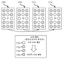
본 발명의 부가의 실시예는 관리기 유닛에 관한 것이다. 관리기 유닛은 샘플 컨테이너 내에 복수의 샘플을 유지하도록 구성된 복수의 입력 레인을 포함한다. 짧은 소요 시간(short turn-around time: STAT) 레인이 샘플 컨테이너 내에 STAT 샘플을 유지하도록 구성된다. 에러 레인이 에러와 연계된 샘플 컨테이너 내에 샘플을 유지하도록 구성된다.An additional embodiment of the present invention relates to a manager unit. The manager unit includes a plurality of input lanes configured to hold a plurality of samples in a sample container. A short turn-around time (STAT) lane is configured to maintain the STAT sample in the sample container. The error lane is configured to keep the sample in the sample container associated with the error.
본 발명의 다른 실시예는 방법에 관한 것이다. 방법은 관리기 유닛 내의 복수의 입력 레인 내에 복수의 샘플 컨테이너를 배치하는 단계를 포함한다. 제1 샘플 컨테이너 내의 제1 샘플이 복수의 입력 레인으로부터 회수된다. 제1 샘플이 STAT 샘플인지 여부가 판정되고, 제1 샘플이 관리기 유닛 내의 STAT 레인 내에 배치된다. 제2 샘플 컨테이너 내의 제2 샘플과 연계된 에러가 결정되고, 샘플은 관리기 유닛 내의 에러 레인 내에 배치된다.Another embodiment of the present invention relates to a method. The method includes placing a plurality of sample containers in a plurality of input lanes in a manager unit. A first sample in the first sample container is retrieved from a plurality of input lanes. It is determined whether or not the first sample is a STAT sample, and the first sample is placed in the STAT lane in the manager unit. The error associated with the second sample in the second sample container is determined and the sample is placed in the error lane in the manager unit.
본 발명의 다른 실시예는 수송 트랙 및 수송 트랙에 인접한 출력 유닛을 갖는 시스템에 관한 것이다. 출력 유닛은 복수의 출력 서랍, 샘플 컨테이너를 수용하기 위한 버퍼 영역 및 수송 트랙으로부터 샘플 컨테이너를 회수하고 샘플 컨테이너를 버퍼 영역 내에 배치하도록 구성된 파지기 유닛을 포함한다.Another embodiment of the present invention is directed to a system having an output unit adjacent to a transport track and a transport track. The output unit includes a plurality of output drawers, a buffer area for receiving the sample container, and a holding unit configured to retrieve the sample container from the transport track and place the sample container in the buffer area.
본 발명의 부가의 실시예는 방법에 관한 것이다. 방법은 수송 트랙 상의 캐리어로부터 샘플 캐리어 내의 샘플을 회수하는 단계를 포함한다. 수송 트랙은 버퍼 영역 및 복수의 서랍을 포함하는 출력 유닛에 인접한다. 샘플 컨테이너가 버퍼 영역 내에 배치된다.A further embodiment of the invention relates to a method. The method includes recovering a sample in a sample carrier from a carrier on a transport track. The transport track is adjacent to an output unit comprising a buffer area and a plurality of drawers. A sample container is placed in the buffer area.
본 발명의 다른 실시예는 시스템에 관한 것이다. 시스템은 수송 트랙 및 수송 트랙에 인접한 출력 유닛을 포함한다. 출력 유닛은 복수의 출력 서랍, 샘플 컨테이너를 수용하기 위한 버퍼 영역 및 파지기 유닛을 포함한다. 파지기 유닛은 수송 트랙으로부터 샘플 컨테이너를 회수하고 샘플 컨테이너를 버퍼 영역에 배치하도록 구성된다.Another embodiment of the present invention relates to a system. The system includes an output unit adjacent to the transport track and the transport track. The output unit includes a plurality of output drawers, a buffer area for accommodating the sample container, and a gripper unit. The gripper unit is configured to retrieve the sample container from the transport track and place the sample container in the buffer area.
본 발명의 다른 실시예는 방법에 관한 것이다. 방법은 수송 트랙 상의 캐리어로부터 샘플 컨테이너 내의 샘플을 회수하는 단계를 포함한다. 수송 트랙은 출력 유닛에 인접한다. 출력 유닛은 버퍼 영역 및 복수의 서랍을 포함한다. 샘플 컨테이너는 버퍼 영역 내에 배치된다.Another embodiment of the present invention relates to a method. The method includes recovering a sample in a sample container from a carrier on a transport track. The transport track is adjacent to the output unit. The output unit includes a buffer area and a plurality of drawers. A sample container is placed in the buffer area.
본 발명의 부가의 실시예는 시스템에 관한 것이다. 시스템은 제1 샘플 컨테이너 파지기 및 제2 샘플 컨테이너 파지기를 포함한다. 제1 샘플 컨테이너 파지기는 입력 모듈의 서랍으로부터 분배 영역으로 샘플 컨테이너를 수송하도록 구성된다. 제2 샘플 컨테이너 파지기는 샘플 컨테이너를 원심 분리기 어댑터로 수송하도록 구성된다. 제2 샘플 컨테이너 파지기는 또한 샘플 컨테이너를 이송 디바이스로 수송하도록 구성된다.An additional embodiment of the present invention relates to a system. The system includes a first sample container holder and a second sample container holder. The first sample container dispenser is configured to transport the sample container from the drawer of the input module to the dispensing area. The second sample container dispenser is configured to transport the sample container to the centrifuge adapter. The second sample container dispenser is also configured to transport the sample container to the transport device.
본 발명의 다른 실시예는 방법에 관한 것이다. 방법은 제1 샘플 컨테이너 파지기에 의해 입력 모듈의 서랍으로부터 분배 영역으로 샘플 컨테이너를 수송하는 단계를 포함한다. 샘플 컨테이너가 원심 분리를 요구하면, 제2 샘플 컨테이너 파지기는 샘플 컨테이너를 원심 분리기 어댑터로 수송한다. 어댑터 셔틀이 원심 분리기 어댑터를 원심 분리기 영역으로 수송한다. 원심 분리기 어댑터 파지기는 원심 분리기 어댑터를 원심 분리기 내로 수송한다. 원심 분리기 어댑터 파지기가 원심 분리기로부터 어댑터 셔틀로 원심 분리기 어댑터 파지기를 수송한다. 제3 샘플 컨테이너 파지기가 샘플 컨테이너를 원심 분리기 어댑터로부터 컨베이어 트랙으로 수송한다. 샘플 컨테이너가 원심 분리를 요구하지 않으면, 제2 샘플 컨테이너 파지기는 샘플 컨테이너를 컨베이어 디바이스로 수송한다. 샘플 컨테이너는 제2 샘플 컨테이너 파지기에 의해 컨베이어 디바이스 상의 샘플 컨테이너 내로 삽입된다.Another embodiment of the present invention relates to a method. The method includes transporting a sample container from a drawer of an input module to a dispensing area by a first sample container dispenser. If the sample container requires centrifugation, the second sample container dispenser transports the sample container to the centrifuge adapter. The adapter shuttle delivers the centrifuge adapter to the centrifuge area. Centrifuge Adapter The handler transports the centrifuge adapter into the centrifuge. The centrifuge adapter grasper transports the centrifuge adapter grinder from the centrifuge to the adapter shuttle. A third sample container dispenser transports the sample container from the centrifuge adapter to the conveyor track. If the sample container does not require centrifugation, the second sample container dispenser transports the sample container to the conveyor device. The sample container is inserted into the sample container on the conveyor device by the second sample container dispenser.
본 기술의 이들 및 다른 실시예들이 이하 보다 상세하게 기술된다.These and other embodiments of the present technique are described in more detail below.
상이한 실시예의 성질 및 장점의 추가의 이해가 이하의 도면을 참조하여 실현될 수도 있다.
도 1은 실험실 자동화 시스템의 페이즈(phase)와 연계된 구성 요소의 다이어그램을 도시한다.
도 2a는 실험실 자동화 시스템의 분석전 페이즈와 연계된 구성 요소의 다이어그램을 도시한다.
도 2b는 본 발명의 실시예에 따른 구역(region) 개념-튜브 특성을 도시한다.
도 3은 분취기 모듈 내의 구성 요소의 다이어그램을 도시한다.
도 4a 내지 도 4e는 출력/분류기 모듈과 연계된 구성 요소의 구성의 다이어그램을 도시한다.
도 4f는 본 발명의 실시예에 따른 구역 개념-WML 인스트럭션(instruction)을 도시한다.
도 5는 캡핑 디바이스에 결합된 분류기 모듈의 구성의 다이어그램을 도시한다.
도 6은 실험실 자동화 시스템의 분석후 페이즈 내의 구성 요소의 다이어그램을 도시한다.
도 7a는 관리기 유닛과 연계된 구성 요소의 다이어그램을 도시한다.
도 7b는 다른 관리기 유닛과 연계된 구성 요소의 다이어그램을 도시한다.
도 8a 및 도 8b는 원심 분리기 유닛과 연계된 구성 요소의 다이어그램을 도시한다.
도 9는 실험실 자동화 시스템의 분석전 페이즈 내의 구성 요소의 다이어그램을 도시한다.
도 10은 관리기 유닛과 연계된 구성 요소의 다이어그램을 도시한다.
도 11은 이중 원심 분리 유닛과 연계된 구성 요소의 다이어그램을 도시한다.
도 12는 이중 분취기 유닛과 연계된 구성 요소의 다이어그램을 도시한다.
도 13a 및 도 13b는 출력/분류기 유닛과 연계된 구성 요소의 다이어그램을 도시한다.
도 14a 및 도 14b는 분석전 페이즈 시스템 작업흐름의 예시적인 예를 도시하는 흐름도의 부분이다.
도 15는 적절한 샘플을 선택하기 위한 예시적인 프로세스를 도시하는 흐름도이다.
도 16은 원심 분리기를 위한 예시적인 어댑터 스왑(swap) 시퀀스를 도시한다.
도 17은 원심 분리기를 위한 예시적인 어댑터 로딩 시퀀스를 도시한다.
도 18은 원심 분리기 회전자를 도시한다.
도 19는 3개의 독립적으로 이동 가능한 방향 x-, y- 및 z-를 갖는 데카르트(Cartesian) 또는 갠트리(gantry) 로봇의 예를 도시한다.
도 20a 내지 도 20c는 파지기 유닛의 실시예의 측면도를 도시한다.
도 21은 샘플 튜브 검출 및 분석을 위한 카메라 유닛의 예시적인 다이어그램을 도시한다.
도 22는 별개의 파장에서 흡수 및 투과 곡선의 분석을 이용하는 샘플 레벨 검출의 예를 도시한다.
도 23은 조합 로봇의 다이어그램을 도시한다.
도 24 내지 도 27은 실시예에 따른 예시적인 화상 분석 디바이스의 블록 다이어그램을 도시한다.
도 28a 내지 도 28c는 샘플 튜브 또는 래크 검출 및 분석을 위한 카메라 유닛의 예를 도시한다.
도 29는 평면도 화상에 기초하여 샘플 래크 내의 샘플 튜브의 식별의 강조된 분석된 화상 및 원본 화상의 예시적인 오버레이 화상을 도시한다.
도 30은 예시적인 샘플 튜브를 도시한다.
도 31a 및 도 31b는 긴급 샘플 지시기를 갖는 예시적인 캡의 평면도를 도시한다.
도 32a 및 도 32b는 원심 분리 지시기의 예시적인 컬러 지시기를 도시한다.
도 33 및 도 34는 감압식 디바이스를 갖는 캡을 도시한다.
도 35는 유닛 또는 모듈로서 배열된 주 수송 시스템 및 다수의 프로세싱 스테이션을 도시하는 물체 수송 시스템의 평면도 다이어그램의 일 예를 도시한다.
도 36은 주 수송 유닛에 부착되고 탈착된 프로세싱 모듈을 위한 측면도 다이어그램의 예를 도시한다.
도 37은 수송 유닛을 갖는 프로세싱 모듈의 측면도 다이어그램의 예를 도시한다.
도 38a 내지 도 38c는 샘플 튜브 내에 삽입되는 샘플 튜브의 다이어그램을 도시한다.
도 39는 샘플 튜브 캐리어의 조오(jaw)의 평면도 다이어그램을 도시한다.
도 40은 퍽 수송 시스템을 이용하는 실험실 수송 시스템의 전달 경로 배열의 변형예의 부분 사시도의 일 예를 도시한다.
도 41은 실험실 제품 수송 요소의 측면 사시도의 일 예를 도시한다.
도 42는 실험실 제품 수송 요소의 측면 섹션의 일 예를 도시한다.
도 43은 실험실 제품 수송 요소의 저부 사시도의 일 예를 도시한다.
도 44는 외부 측면 보호 없는 실험실 제품 수송 요소의 일 예를 도시한다.
도 45는 전달 경로의 절결부의 일 예를 도시한다.
도 46은 컨베이어 수송 시스템의 전환기 및 병합기 기능의 예시적인 다이어그램을 도시한다.
도 47은 컨베이어 수송 시스템의 전달 기능의 예시적인 다이어그램을 도시한다.
도 48은 컨베이어 수송 시스템의 결합된 전환 및 병합 기능의 예시적인 다이어그램을 도시한다.
도 49는 컨베이어 수송 시스템의 정지 기능 및 로케이팅(locating) 기능의 예시적인 다이어그램을 도시한다.
도 50은 검체 컨테이너가 컨베이어 트랙을 따라 샘플 캐리어에 의해 수송되는 종래의 컨베이어 수송 시스템을 도시한다.
도 51은 자기 감쇠 구성 요소를 갖는 검체 수송 시스템의 예시적인 샘플 캐리어를 도시한다.
도 52는 전환 아암 자석을 갖는 예시적인 전환 아암의 평면도이다.
도 53은 예시적인 링 자석의 다이어그램이다.
도 54는 예시적인 전환 아암 자석의 다이어그램이다.
도 55는 컨베이어 수송 시스템 내의 자기 감쇠의 예시적인 흐름도를 도시한다.
도 56은 분취 모듈을 작동하는 예시적인 방법을 위한 흐름도를 도시한다.
도 57은 본 발명의 실시예에 따른 제1 분취기 모듈의 평면도를 도시한다. 제1 분취기 모듈은 다수의 루핑된 레인(looped lane)을 포함한다.
도 58a는 본 발명의 실시예에 따른 제2 분취기 모듈의 평면도를 도시한다. 제2 분취기 모듈은 디스크형 물체의 형태의 회전형 게이트웨이 디바이스를 포함한다.
도 58b는 본 발명의 실시예에 따른 제4 분취기 모듈의 평면도를 도시한다. 제4 분취기 모듈은 선형 바아의 형태의 회전형 게이트웨이 디바이스를 포함한다.
도 59는 본 발명의 실시예에 따른 제3 분취기 모듈의 평면도를 도시한다. 제3 분취기 모듈은 선형 레인 및 독립적으로 이동 가능한 캐리어를 포함한다.
도 60은 예시적인 비접촉식 샘플 튜브 특성화 센서 시스템의 다이어그램을 도시한다.
도 61은 예시적인 샘플 캐리어를 도시한다.
도 62a 내지 도 62c는 예시적인 비접촉식 샘플 튜브 특성화 센서 시스템의 센서의 예시적인 측면도를 도시한다.
도 63은 비접촉식 검체 컨테이너 특성화 시스템을 위한 예시적인 블록 다이어그램이다.
도 64는 비접촉식 검체 컨테이너 특성화 시스템을 위한 흐름도이다.
도 65는 가속도계 기반 원심 분리기 불균형 센서의 예시적인 블록 다이어그램을 도시한다.
도 66a 내지 도 66c는 가속도계 기반 원심 분리기 불균형 센서를 위한 예시적인 회로 다이어그램을 도시한다.
도 67은 원심 분리기 불균형 센서를 위한 흐름도를 도시한다.
도 68은 예시적인 원심 분리기 서랍을 도시한다.
도 69는 제1 실시예에 따른 원심 분리기 서랍을 위한 예시적인 케이블 관리를 도시한다.
도 70a 및 도 70b는 제2 실시예에 따른 원심 분리기 서랍을 위한 예시적인 케이블 관리 디바이스를 도시한다.
도 71은 원심 분리기 서랍을 위한 예시적인 자기 래치를 도시한다.
도 72a 내지 도 72c는 원심 분리기 서랍을 위한 예시적인 기계적 래치를 도시한다.
도 73은 원심 분리기 서랍을 위한 예시적인 압축 댐퍼를 도시한다.
도 74는 원심 분리기 서랍을 위한 예시적인 커버를 도시한다.
도 75는 원심 분리기 서랍 상에 원심 분리기를 로딩하기 위한 예시적인 작업흐름을 도시한다.
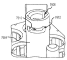
도 76a 및 도 76b는 제1 실시예에 따른 예시적인 원심 분리기 어댑터 파지기를 도시한다.
도 77a 및 도77b는 제1 실시예에 따른 예시적인 원심 분리기 어댑터 파지기를 도시한다.
도 78은 원심 분리기 어댑터를 수송하기 위해 사용된 예시적인 셔틀을 도시한다.
도 79a 내지 도 79c는 예시적인 후크 들어올림(lift-up) 방지 디바이스를 도시한다.
도 80은 예시적인 자기 들어올림 방지 디바이스를 도시한다.
도 81 내지 도 83은 샘플을 자동으로 처리하기 위한 장치를 도시한다.
도 84는 예시적인 컴퓨터 장치의 블록 다이어그램을 도시한다.A further understanding of the nature and advantages of the different embodiments may be realized with reference to the following drawings.
Figure 1 shows a diagram of the components associated with the phase of a laboratory automation system.
Figure 2a shows a diagram of the components associated with the pre-analysis phase of the laboratory automation system.
FIG. 2B illustrates a region concept-tube characteristic according to an embodiment of the present invention.
Figure 3 shows a diagram of the components in the analyzer module.
Figures 4A-4E show diagrams of the configuration of the components associated with the output / sorter module.
FIG. 4F shows a Zoning Concept-WML instruction according to an embodiment of the present invention.
Figure 5 shows a diagram of the configuration of a sorter module coupled to a capping device.
Figure 6 shows a diagram of the components in a post-analysis phase of a laboratory automation system.
Figure 7A shows a diagram of the components associated with the manager unit.
Figure 7B shows a diagram of the components associated with other manager units.
Figures 8a and 8b show diagrams of components associated with the centrifuge unit.
Figure 9 shows a diagram of the components in the pre-analysis phase of the laboratory automation system.
Figure 10 shows a diagram of the components associated with the manager unit.
Figure 11 shows a diagram of the components associated with the dual centrifuge unit.
Figure 12 shows a diagram of the components associated with a dual atomizer unit.
13A and 13B show a diagram of the components associated with the output / classifier unit.
14A and 14B are part of a flow chart illustrating an exemplary example of a pre-analysis phase system workflow.
15 is a flow chart illustrating an exemplary process for selecting an appropriate sample.
Figure 16 illustrates an exemplary adapter swap sequence for a centrifuge.
Figure 17 illustrates an exemplary adapter loading sequence for a centrifuge.
Figure 18 shows a centrifuge rotor.
Figure 19 shows an example of a Cartesian or gantry robot with three independently movable directions x-, y- and z-.
20A to 20C show side views of an embodiment of a gripper unit.
Figure 21 shows an exemplary diagram of a camera unit for sample tube detection and analysis.
Figure 22 shows an example of sample level detection using analysis of absorption and transmission curves at distinct wavelengths.
23 shows a diagram of a combination robot.
Figures 24-27 illustrate a block diagram of an exemplary image analysis device according to an embodiment.
28A to 28C show examples of camera units for sample tube or rack detection and analysis.
29 illustrates an exemplary overlay image of an original image and an emphasized analyzed image of an identification of a sample tube in a sample rack based on a plan view image.
Figure 30 shows an exemplary sample tube.
Figures 31A and 31B show a top view of an exemplary cap with an emergency sample indicator.
Figures 32A and 32B illustrate an exemplary color indicator of a centrifuge indicator.
33 and 34 show a cap with a depressurized device.
35 shows an example of a top view diagram of an object transport system that shows a main transport system and a plurality of processing stations arranged as a unit or module.
36 shows an example of a side view diagram for a processing module attached to and detached from a main transport unit.
Figure 37 shows an example of a side view diagram of a processing module with a transport unit.
Figures 38A-C illustrate a diagram of a sample tube inserted into a sample tube.
Figure 39 shows a top view diagram of the jaw of the sample tube carrier.
40 illustrates an example of a partial perspective view of a variation of the delivery path arrangement of a laboratory transport system utilizing a puck transport system.
Figure 41 shows an example of a side perspective view of a laboratory product transport element.
Figure 42 shows an example of a side section of a laboratory product transport element.
Figure 43 shows an example of a bottom perspective view of a laboratory product transport element.
Figure 44 shows an example of a laboratory product transport element without exterior side protection.
45 shows an example of a cutout portion of the transmission path.
Figure 46 illustrates an exemplary diagram of the diverter and merge function of the conveyor transport system.
Figure 47 shows an exemplary diagram of the transfer function of a conveyor transport system.
Figure 48 shows an exemplary diagram of the combined switching and merging function of the conveyor transport system.
Figure 49 shows an exemplary diagram of the stopping and locating function of the conveyor transport system.
Figure 50 illustrates a conventional conveyor transport system in which a sample container is transported by a sample carrier along a conveyor track.
Figure 51 shows an exemplary sample carrier of a sample transport system having a magnetic damping component.
52 is a plan view of an exemplary switching arm with a switching arm magnet;
53 is a diagram of an exemplary ring magnet.
54 is a diagram of an exemplary switching arm magnet.
55 shows an exemplary flow chart of magnetic decay in a conveyor transport system.
Figure 56 shows a flow diagram for an exemplary method of operating an aliquot module.
57 shows a top view of a first analyzer module according to an embodiment of the present invention. The first fractionator module comprises a plurality of looped lanes.
58A shows a top view of a second analyzer module in accordance with an embodiment of the present invention. The second atomizing module comprises a rotatable gateway device in the form of a disk-like object.
FIG. 58B shows a top view of a fourth separator module according to an embodiment of the present invention. FIG. The fourth quench module includes a rotatable gateway device in the form of a linear bar.
59 shows a top view of a third analyzer module according to an embodiment of the present invention. The third tractive module comprises a linear lane and an independently movable carrier.
Figure 60 shows a diagram of an exemplary non-contact sample tube characterization sensor system.
61 shows an exemplary sample carrier.
62A-C illustrate exemplary side views of a sensor of an exemplary non-contact sample tube characterization sensor system.
63 is an exemplary block diagram for a non-contact sample container characterization system.
64 is a flow chart for a non-contact sample container characterization system.
65 illustrates an exemplary block diagram of an accelerometer-based centrifuge imbalance sensor.
66A-C illustrate exemplary circuit diagrams for an accelerometer-based centrifugal imbalance sensor.
67 shows a flow chart for a centrifugal imbalance sensor.
68 shows an exemplary centrifuge drawer.
69 shows an exemplary cable management for a centrifuge drawer according to the first embodiment.
70A and 70B illustrate an exemplary cable management device for a centrifuge drawer according to the second embodiment.
Figure 71 illustrates an exemplary magnetic latch for a centrifuge drawer.
72A-72C illustrate exemplary mechanical latches for a centrifuge drawer.
73 illustrates an exemplary compression damper for a centrifuge drawer.
74 shows an exemplary cover for a centrifuge drawer.
Figure 75 illustrates an exemplary work flow for loading a centrifuge on a centrifuge drawer.
76A and 76B illustrate an exemplary centrifuge adapter holder according to the first embodiment.
77A and 77B illustrate an exemplary centrifuge adapter holder according to the first embodiment.
78 illustrates an exemplary shuttle used to transport a centrifuge adapter.
79A-79C illustrate an exemplary lift-up prevention device.
80 illustrates an exemplary self-lifting device.
81 to 83 show an apparatus for automatically processing samples.
84 shows a block diagram of an exemplary computer device.
본 발명의 기술의 실시예는 의료용 검체를 처리하기 위한 분석 의료용 실험실 시스템 및 방법에 관한 것이다. 이들 실시예는, 더 상세히 후술되는 바와 같이, 이들 실시예가 다른 장점들 중에서도, 더 높은 속도, 정확성, 효율 및 오염의 방지를 제공하기 때문에 유리하다. 전술된 바와 같이, 다수의 종래의 실험실 시스템은 실험실 전체에 걸쳐 독립형 유닛을 사용하는 프로세스를 가질 수도 있어, 검체가 각각의 독립형 유닛 사이에 수동으로 수송되는 것을 필요로 하고, 반면에 다른 것들은 이송 시스템을 갖는 유닛들의 일부와 연결하여 검체를 유닛간에 이동시킬 수도 있다. 부가적으로, 전술된 바와 같이, 상이한 제조업자들로부터의 샘플 튜브 크기 및 장비는 종래의 실험실 시스템에서 제약일 수도 있다. 이러한 종래의 기술은 저속이고 부정확하다. 본 발명의 기술의 실시예는 더 많은 범용 구성 요소를 사용함으로써 그리고 대부분의 실험실 시스템에 의해 요구된 기능을 5개의 기본 기능 유닛, (1) 관리기, (2) 원심 분리기, (3) 분취기, (4) 출력/분류기 및 (5) 저장 유닛으로 그룹화함으로써 상이한 실험실 유닛 및 수송 시스템, 샘플 튜브 크기 및 제조업자를 수용하는 것이 가능한 모듈형 실험실 시스템을 제공한다. 이들 5개의 기본 기능 유닛은 더 상세히 후술될 것이다. 몇몇 경우에, 유닛들은 "모듈들"이라 칭할 수도 있다.An embodiment of the technique of the present invention relates to an analytical medical laboratory system and method for processing medical specimens. These embodiments are advantageous, as will be described in greater detail below, because these embodiments provide, among other advantages, higher speed, accuracy, efficiency and prevention of contamination. As described above, many conventional laboratory systems may have processes that use stand-alone units throughout the lab, requiring that the specimens be manually transported between each stand-alone unit, while others require the transfer system To move the specimen between the units. Additionally, as discussed above, sample tube sizes and equipment from different manufacturers may be constraints in conventional laboratory systems. This conventional technique is slow and inaccurate. Embodiments of the technology of the present invention can be implemented by using more general purpose components and by providing functionality required by most laboratory systems to five basic functional units, (1) a manager, (2) a centrifuge, (3) (4) an output / sorter, and (5) storage units, thereby accommodating different laboratory units and transport systems, sample tube sizes and manufacturers. These five basic functional units will be described in more detail below. In some cases, units may be referred to as "modules ".
실험실 시스템은 중앙 제어기 또는 스케쥴러를 사용하여 제어된 프로세스를 작동할 수 있다. 지능형 스케쥴러의 제어 하에 샘플을 유지함으로써, 시스템은 모든 기구(instrument)의 효율적인 사용을 제공할 수도 있다. 시스템은 일관적인 최소 소요 시간(turnaround time)을 유지하고, 프로세스의 제어를 유지하고 단지 이들 기구가 준비되고 이용 가능할 때에만 기구에 샘플을 전달함으로써 전체 시스템의 처리량을 최대화할 수 있다.The laboratory system can operate a controlled process using a central controller or a scheduler. By maintaining samples under the control of the intelligent scheduler, the system may provide efficient use of all instruments. The system can maximize the throughput of the entire system by maintaining consistent minimum turnaround times, maintaining control of the process, and delivering samples to the instrument only when these instruments are ready and available.
본 발명의 실시예에서, 샘플은 검체 컨테이너 내에 수납되고 실험실 자동화 시스템에 의해 처리될 수 있다. "샘플 컨테이너", "샘플 튜브" 및 "튜브"로도 칭하는 "검체 컨테이너"는 임의의 적합한 형상 또는 형태를 가질 수도 있다. 몇몇 실시예에서, 검체 컨테이너는 샘플 튜브의 형태일 수도 있다. 예시적인 검체 컨테이너는 폐쇄 하단부 및 개방 상단부를 갖는 샘플 튜브일 수도 있다. 몇몇 샘플 튜브는 3:1 이상의 형상비(aspect ratio)를 갖는다. 검체 컨테이너는 플라스틱, 글래스 등을 포함하는 임의의 적합한 재료로 제조될 수도 있다. 샘플 튜브 본체의 개방 단부를 덮어 부착하도록 구성된 캡이 샘플 튜브와 함께 사용될 수도 있다.In an embodiment of the invention, the sample is contained within a sample container and can be processed by a laboratory automation system. The "sample container", also referred to as "sample container", "sample tube", and "tube" may have any suitable shape or shape. In some embodiments, the sample container may be in the form of a sample tube. An exemplary sample container may be a sample tube having a closed bottom end and an open top end. Some sample tubes have an aspect ratio of 3: 1 or greater. The sample container may be made of any suitable material, including plastic, glass, and the like. A cap configured to cover and adhere the open end of the sample tube body may be used with the sample tube.
본 발명의 실시예에서, 하나 이상의 검체 컨테이너가 수송을 위해 "샘플 캐리어"(또한 "캐리어" 또는 "샘플 컨테이너 홀더"라 칭함) 내에 삽입될 수도 있다. 샘플 캐리어는 하나 이상의 검체 컨테이너를 직립 자세로 유지하고 캐리어가 이송 시스템을 따라 수송됨에 따라 안정성을 제공할 수도 있다. 몇몇 실시예에서, 샘플 캐리어는 단일 검체 컨테이너를 수용하도록 구성된 퍽 또는 원통형 리셉터클(receptacle)일 수도 있다. 샘플 캐리어는 검체 컨테이너의 내용물이 보여지고 분석되게 하기 위한 수직 슬릿을 가질 수도 있다. 몇몇 경우에, 샘플 캐리어는 검체 컨테이너를 수용하기 위한 리세스의 어레이를 갖는 샘플 튜브 래크의 형태일 수도 있다.In an embodiment of the invention, one or more sample containers may be inserted into a "sample carrier" (also referred to as a "carrier" or "sample container holder") for transport. The sample carrier may maintain one or more sample containers in an upright posture and provide stability as the carrier is transported along the transfer system. In some embodiments, the sample carrier may be a puck or a cylindrical receptacle configured to receive a single sample container. The sample carrier may have a vertical slit to allow the contents of the sample container to be viewed and analyzed. In some cases, the sample carrier may be in the form of a sample tube rack having an array of recesses for receiving a sample container.
실험실 시스템은 로봇식 아암 상에 장착된 하나 이상의 로봇식 파지기 유닛을 또한 이용할 수도 있다. 각각의 로봇식 아암 유닛은 샘플 튜브를 파지하기 위한 로봇식 파지기를 가질 수 있고, 샘플 튜브에 대한 정보를 검출하기 위한 하나 이상의 수단을 구비할 수도 있다. 용어 "파지기" 및 "로봇식 파지기"는 본 명세서에서 상호 교환 가능하게 사용된다. 샘플 튜브에 대한 정보를 검출하기 위한 수단은 래크 내의 복수의 샘플 튜브들 중의 샘플 튜브를 식별하기 위한, 카메라와 같은 제1 촬영 디바이스를 포함할 수도 있다. 식별된 샘플 튜브는 파지기에 의해 파지된다. 샘플 튜브에 대한 정보를 검출하기 위한 수단은 파지된 샘플 튜브의 화상을 얻기 위한 제2 촬영 디바이스를 더 포함할 수도 있다. 샘플 튜브 내의 액체의 레벨은 제2 촬영 디바이스에 의해 얻어진 화상으로부터 또는 로봇식 아암 유닛에 결합된 이미터(emitter) 및 수신기 유닛을 사용하여 투과 측정으로부터 결정될 수도 있다. 트랙 상에 장착된 카메라를 갖고 따라서 튜브가 식별될 수 있기 전에 모든 샘플 튜브가 트랙 상에 있는 것을 필요로 하는 종래의 시스템에 비교하여, 본 명세서에 설명된 실험실 시스템은 컨베이어 트랙 상에 배치되기 전에 샘플 튜브를 식별할 수 있다. 그 결과, 컨베이어 상에서 수송될 필요가 없는 샘플은 단지 샘플 튜브 식별의 목적으로 컨베이어 상에 배치되지 않는다. 또한, 긴급 샘플은 컨베이어 트랙 상의 우선순위화된 배치를 가질 수 있다.The laboratory system may also utilize one or more robotic gripper units mounted on a robotic arm. Each robotic arm unit may have a robotic gripper for gripping the sample tube and may have one or more means for detecting information about the sample tube. The terms "gripper" and "robotic gripper" are used interchangeably herein. The means for detecting information about the sample tube may include a first imaging device, such as a camera, for identifying the sample tube of the plurality of sample tubes in the rack. The identified sample tube is held by a gripper. The means for detecting information about the sample tube may further comprise a second imaging device for obtaining an image of the gripped sample tube. The level of liquid in the sample tube may be determined from the image obtained by the second imaging device or from the transmission measurement using an emitter and receiver unit coupled to the robotic arm unit. Compared to conventional systems that have a camera mounted on a track and thus require all of the sample tubes to be on a track before the tube can be identified, the laboratory system described herein can be placed on a conveyor track The sample tube can be identified. As a result, samples that do not need to be transported on the conveyor are not placed on the conveyor for the purpose of sample tube identification only. In addition, the emergency sample may have a prioritized placement on the conveyor track.
실험실 시스템 내의 복수의 로봇식 파지기 유닛의 사용은 또한 샘플 처리 효율을 증가시킬 수 있다. 입력 모듈 파지기와 같은 제1 파지기는 전술된 바와 같이 샘플 튜브를 식별하고 데이터 측정을 행할 수 있다. 제1 파지기가 샘플 튜브를 분배 영역으로 전달한 후에, 분배 영역 파지기와 같은 제2 파지기는 샘플 튜브를 원심 분리기 모듈 또는 컨베이어와 같은 후속 모듈로 전달할 수 있다. 다중 파지기의 사용은 컨베이어 트랙 상에 모든 샘플을 수신하고, 식별하고, 로딩하기 위해 단지 단일의 파지기만을 사용하는 종래의 시스템에 비해 처리 효율의 증가를 허용한다.
The use of a plurality of robotic gripper units in a laboratory system can also increase the sample processing efficiency. A first gripper, such as an input module gripper, can identify the sample tube and perform data measurements as described above. After the first gripper delivers the sample tube to the dispensing area, a second dispensing machine, such as a dispensing area dispenser, can deliver the sample tube to a subsequent module such as a centrifuge module or conveyor. The use of a multiplexer allows for an increase in processing efficiency over conventional systems that use only a single stitcher to receive, identify, and load all samples on a conveyor track.
I. 전체 시스템I. Overall System
A. 실험실 시스템의 A. of the laboratory system 페이즈Phase
도 1은 환자 샘플을 처리하기 위한 의료용 실험실 시스템의 일 실시예를 도시한다. 실험실 시스템은 연계 페이즈(102), 분석전 페이즈(104), 분석 페이즈(106) 및 분석후 페이즈(108)와 연계된 구성 요소들을 포함한다.Figure 1 illustrates one embodiment of a medical laboratory system for treating a patient sample. The laboratory system includes components associated with
1. 연계 1. Connection 페이즈Phase
연계 페이즈(102)는 실험실 시스템의 제1 페이즈일 수 있다. 이 페이즈 중에, 환자 정보, 검체에 대한 요구된 시험 및 고유 실험실 식별자(예를 들어, 바코드)와 같은 검체에 관한 다양한 정보가 검체 컨테이너와 연계될 수도 있다. 몇몇 실시예에서, 연계 페이즈는 수동으로 취급된다. 예를 들어, 몇몇 실시예에서, 실험실 기술자(이하, "사용자"라 칭함)는 샘플에 우선순위를 할당할 수 있다. 바람직한 실시예에서, 스케쥴링 시스템이 우선순위 및 어떻게 샘플들이 처리되어야 하는지에 관련된 다른 정보를 결정하는데 사용된다. 샘플은 특정 입구점에서 래크 내에 또는 시스템 상에 직접 로딩될 수도 있다. 몇개의 기본 우선순위 레벨(예를 들어, 긴급 또는 고 우선순위, 중 우선순위, 저 우선순위 등)로 샘플들을 그룹화하는 것이 더 일관적인 소요 시간을 제공하기 위해 바람직할 수도 있지만, 이는 필수적인 것은 아니다. 환자 샘플을 처리하는 것은 사용자에 의해 규정된 임의의 우선순위에 기초할 수 있다. 그러나, 우선순위가 지정되지 않으면, 우선순위는 소요 시간을 최소화하는 것, 처리량을 최대화하는 것, 프로세스의 이용 가능성과 같은 인자에 기초하여 할당될 수 있다.The
2. 2. 분석전Before analysis 페이즈Phase
분석전 페이즈(104)는 분석을 위한 환자 샘플을 준비하는 것을 포함할 수 있다. 분석전 페이즈(104) 중에, 환자 및 시험 정보가 해독될 수 있고, 환자를 위한 프로세스가 계획될 수 있고, 품질 검사가 수행될 수도 있고, 샘플은 그 구성 성분으로 분리될 수도 있고(예를 들어, 원심 분리됨), 샘플은 다수의 검체 컨테이너 내에 분할될 수도 있고(예를 들어, 분취됨), 그리고/또는 샘플은 하나 이상의 분석기 및/또는 래크로 전달될 수 있다. 분석전 페이즈(104)는 연구실 시스템 내의 상이한 기구 및 상이한 분석기로의 샘플의 흐름을 관리할 수 있다. 이 프로세스 관리는 시스템이 효율적으로 그리고 최소의 기구에 의해 작동하는 것을 허용할 수도 있다. 부가적으로, 분석전 페이즈(104) 중에 발생하는 스케쥴링은 샘플의 효율적인 처리를 가능하게 한다.The
시스템의 실시예는 환자 샘플을 가능한 한 신속하게 식별하고, 각각의 샘플의 최선의 스케쥴링을 결정하여 분석 프로세스의 일관적인 최소 소요 시간 및 최대 처리량을 제공할 수 있다. 프로세스의 단계들 및 이들 단계들의 편성은 시스템으로의 입력 또는 시스템의 다른 스테이션에서 검체 컨테이너의 누적을 회피하도록 설계된다. 실험실 시스템의 모듈은 상류측 프로세스의 최대 처리량에서 샘플의 처리를 허용하는 처리량 속도에서 작동할 수 있다. 그러나, 몇몇 실시예에서, 분취기 유닛에서, 처리량은 상류측의 샘플의 도입에 의해 그리고 각각의 분취 스테이션에서 작은 대기열에 의해 관리될 수도 있다.An embodiment of the system can identify the patient samples as quickly as possible and determine the best scheduling of each sample to provide a consistent minimum time and maximum throughput of the analysis process. The steps of the process and the combination of these steps are designed to avoid input to the system or accumulation of sample containers at other stations in the system. The module of the laboratory system can operate at a throughput rate that allows processing of the sample at the maximum throughput of the upstream process. However, in some embodiments, in the analyzer unit, the throughput may be managed by the introduction of samples on the upstream side and by a small queue on each of the collection stations.
도 2a는 분석전 페이즈(104)와 연계된 구성 요소들의 더 상세한 도면이다. 분석전 페이즈(104)와 연계된 구성 요소들은 입력 모듈(202), 분배 영역(204), 원심 분리기(206), 디캡퍼(decapper)(208), 혈청 인덱스 측정 디바이스(210), 분취기(212) 및 출력/분류기(214)와 같은 모듈을 포함할 수 있다.2A is a more detailed view of the components associated with the
(a) 입력 모듈(a) Input module
도 2a에 도시된 입력 모듈(202)은 검체 컨테이너가 실험실 시스템에 도입되는 지점이다. 튜브의 래크 및/또는 개별 튜브가 수동 작동식 서랍 및/또는 자동화 디바이스일 수 있는 다수의 레인(216) 중 하나 상에 로딩될 수 있다. 도 2a에서, 5개의 레인(216)이 도시되어 있다. 그러나, 실험실 시스템은 임의의 수의 레인(216)을 가질 수 있다. 레인(216)은 자동화된 또는 사용자-설정된 스케쥴링에 따라 우선순위화될 수 있다. 몇몇 실시예에서, 최고 우선순위 레인(짧은 소요 시간 또는 "STAT")은 사용자로부터 개별 튜브의 그룹을 수락하기 위한 고정된 위치를 가질 수도 있다. 일단 튜브들이 STAT 레인에 로딩되면, 이들 튜브는 처리될 다음의 튜브가 된다. 다른 레인들은 임의의 방식으로 상이한 우선순위 레벨이 할당될 수 있다. 예를 들어, 서랍이 수동으로 작동될 때, 서랍들 중 적어도 2개에 하나의 우선순위를 그리고 적어도 2개의 다른 서랍들에 다른 우선순위를 할당하는 것은, 동일한 우선순위의 다른 서랍이 사용자에게 이용 가능한 동안 하나의 서랍 상에서 시스템이 연속적으로 작동하게 할 수도 있다.The
몇몇 실시예에서, 입력 모듈(202)이 샘플의 서랍을 처리하는 동안, 사용자는 서랍이 개방되지 않아야 한다는 것을 통지받을 수도 있다. 예를 들어, 서랍 상의 라이트 또는 서랍 상의 잠금장치(lock)와 같은 지시기가 사용자에게 경고하는데 사용될 수도 있다. 이는 프로세스 완전성을 유지하고 처리량을 최대화하는 것을 도울 수도 있다. 제1 서랍의 내용물의 처리가 완료될 때, 서랍은 이용 가능한 것으로서 사용자에게 식별될 수도 있고, 시스템은 자동으로 다른 서랍을 처리하기 시작할 수도 있다. 부가적으로, 샘플은 입력 모듈 파지기(228)를 사용하여 입력 모듈(202)의 서랍(216)으로 그리고 서랍으로부터 전달될 수 있다(이 서랍은 대안적으로 몇몇 경우에 "레인"이라 칭할 수도 있음).In some embodiments, while the
본 발명의 몇몇 실시예에서, "구역" 개념이 사용될 수 있다. "구역"은 서랍, 래크 홀더, 트레이 및 래크의 사용을 위한 기본적인 추상 개념일 수 있다. 예를 들어, 구역은 본 발명의 일 실시예에서 래크 내의 튜브 위치들의 세트일 수 있다. 구역은 튜브 특성(예를 들어, STAT, 샘플 유형, 사전-스핀, 캡 유형) 또는 단일 처리 인스트럭션이 할당될 수 있다. 본 발명의 실시예에서, 튜브 특성 또는 인스트럭션은 하나 이상의 구역에 할당될 수 있는데, 이는 더 강인한 경로설정 방안을 허용한다.In some embodiments of the invention, the "zone" concept may be used. "Zone" may be a basic abstraction for use of drawers, rack holders, trays, and racks. For example, the zone may be a set of tube locations within the rack in one embodiment of the present invention. The zone may be assigned a tube characteristic (e.g., STAT, sample type, pre-spin, cap type) or a single processing instruction. In an embodiment of the invention, the tube characteristics or instructions may be assigned to one or more zones, which allows for a more robust routing scheme.
도 2b에 도시된 바와 같이, 서랍(242)을 포함하는 서랍 조립체(240) 내의 구역은 특정 튜브 특성[246(a)-1, 246(b)-1, 246(b)-2, 246(c)-1)]을 갖는 래크[246(a), 246(b), 246(c)][서랍(240) 내의 래크 홀더(244) 내에 유지됨] 내의 튜브들의 세트에 맵핑될 수 있다. 각각의 구역은 연계된 튜브 특성[246(a)-1, 246(b)-1, 246(b)-2, 246(c)-1)]의 세트를 갖는다. 몇몇 실시예에서, 시스템은 최적화된 경로를 계산하기 위해 이들 튜브 특성을 사용한다(더 상세히 후술됨). 서브시스템(예를 들어, 원심 분리기, 분취기 등)이 튜브가 처리될 순서(예를 들어, 통상적으로 처리되는 샘플들 전에 STAT 샘플)를 계산하기 위해 튜브 특성을 사용한다.As shown in FIG. 2B, the area within the
(b) 분배 영역 모듈(b) the distribution area module
도 2a를 재차 참조하면, 입력 모듈(202) 내의 레인(216)으로부터, 하나 이상의 분배 영역 파지기(218)는 최고 우선순위 튜브를 선택하고 이를 분배 영역(204)이라 칭하는 고정된 매트릭스에 수송한다. 분배 영역(204)은 실험실 자동화 시스템의 지정된 스테이션으로 샘플 컨테이너를 분배하는 것이 가능하다. 입력 모듈 파지기(228)가 검체를 분배 영역(204)으로 전달함에 따라, 파지기(228)는 검체에 대한 정보를 수집할 수 있다. 예를 들어, 검체 컨테이너 내의 유체의 하나 이상의 액체 레벨이 예를 들어 파지기(228)와 연계된 시스템에 의해 측정될 수도 있다. 몇몇 실시예에서, 샘플 튜브는 예를 들어, 파지기(228)와 연계된 시스템에 의해 촬영될 수도 있다. 이 방식으로 수집된 정보는 튜브의 제조업자, 직경, 높이, 캡 컬러 등을 결정하도록 분석될 수 있다. 샘플의 성분의 체적이 계산될 수 있고, 총 튜브 중량의 추정이 이루어질 수 있다. 이 중량은 이후에 더 상세히 후술되는 바와 같이, 원심 분리기 모듈(206) 내의 원심 분리기 어댑터를 균형화하는 것을 보조하는데 사용될 수 있다.2A, from a
분배 영역(204)이 저 우선순위 튜브로 충전되게 되는 것을 방지하기 위해, 한도가 저 우선순위 입력 레인으로부터 이 영역 내로 로딩된 튜브의 수에 대해 설정될 수 있다. 더욱이, 분배 영역(204)은 STAT 샘플이 입력 모듈(202) 내의 STAT 서랍으로부터 분배 영역(204)으로의 연속적인 액세스를 갖는 것을 보장하기 위한 예비 영역(reserved area)을 가질 수도 있다.In order to prevent the
분배 영역(204)은 시스템이 연계 페이즈(102) 내의 샘플 튜브와 연계된 시험 정보에 액세스하고 샘플을 위한 분석 프로세스를 계획하는 것을 허용하는 유지 영역일 수 있다. 이는 시스템이 시스템 상에서 현재 다른 샘플 튜브에 대해 샘플 튜브의 프로세스를 스케쥴링하는 것을 가능하게 한다. 스케쥴링은 전체 시스템 내의 임의의 단계를 오버로딩하지 않고 우선순위에 기초하여 샘플의 효율적인 처리를 가능하게 하여, 소요 시간 및 처리량의 최적화를 허용한다. 더욱이, 샘플의 스케쥴은 시스템의 활성도 또는 이용 가능성이 변화함에 따라 프로세스 전체에 걸쳐 업데이트될 수 있어, 샘플의 실시간 활성 제어를 제공한다.The
일단 스케쥴이 분배 영역 모듈(204)에 의해 계획되면, 로봇식 파지기(218)는 이어서 분배 영역(204) 내의 튜브의 우선순위에 기초하여 다음의 모듈로 전달될 다음의 튜브인 샘플 튜브를 선택한다. 선택된 샘플 튜브는 분배 영역 모듈(204)에 의해 수행된 분석에 기초하여 분배 영역(204)으로부터 이송 영역(220)으로, 원심 분리기 모듈(206)로 또는 에러 영역(222)을 갖는 출력 서랍으로 수송된다.Once the schedule is planned by the dispense
샘플 튜브가 원심 분리기 모듈(206)로 이동되고 있으면, 튜브는 원심 분리기 회전자의 적절한 균형을 보장하기 위해 조기의 중량 추정에 기초하여 적절한 원심 분리기 어댑터 내에 배치될 수 있다. 원심 분리기 어댑터는 분배 영역(204)으로부터 원심 분리기로 셔틀 상에서 튜브를 운반하는 구성 요소이고, 여기서 로봇식 파지기가 원심 분리기의 버켓(bucket)으로 튜브와 함께 원심 분리기 어댑터를 전달한다.If the sample tube is being moved to the
분배 영역 모듈(204)이 샘플 튜브가 원심 분리를 필요로 하지 않는다고 결정하면, 분배 영역 로봇식 파지기(218)는 하류측 프로세스를 오버로드하지 않기 위해 스케쥴러의 방향에서 캐리어에 적절하게 정렬된 바코드 라벨을 갖는 이송 시스템(220) 상의 캐리어 내로 샘플을 배치한다. 이송 시스템(220) 및 캐리어에 대한 부가의 상세가 후술될 것이다. 캐리어는 이송 시스템 내에 존재할 수 있고 하나 이상의 샘플 컨테이너 또는 튜브를 운반하거나 수송할 수 있는 임의의 적합한 디바이스를 칭할 수 있다. 예시적인 캐리어는 컨테이너 또는 튜브를 유지할 수 있는 리세스를 포함할 수도 있다. 문제점이 샘플에 존재하면(예를 들어, 체적이 너무 낮고, 바코드가 판독 불가능하고, 어떠한 시험 정보도 다운로드되지 않음 등), 샘플 튜브는 에러 영역(222)으로 이동되고, 사용자는 문제점이 통보된다.If the dispense
(c) 원심 분리기 모듈(c) Centrifuge module
샘플 튜브는 분배 영역 모듈(204)이 샘플이 샘플의 분석 전에 원심 분리를 필요로 한다고 결정할 때, 도 2a의 분배 영역(204)으로부터 원심 분리기 모듈(206)로 이동될 수도 있다. 원심 분리기 모듈(206)은 하나 이상의 자동화 원심 분리기[예를 들어, 제1 원심 분리기(206-1) 및 제2 원심 분리기(206-2)] 및 각각의 원심 분리기용 어댑터 셔틀[예를 들어, 제1 어댑터 셔틀(224) 및 제2 어댑터 셔틀(225)]을 포함할 수도 있다. 원심 분리기 모듈(206)은 하나 이상의 로봇식 파지기[예를 들어, 로봇식 파지기(226) 및 로봇식 파지기(227)]를 더 포함할 수도 있다. 몇몇 실시예에서, 로봇식 파지기(226)는 어댑터(224, 225)로부터 원심 분리된 샘플 튜브를 제거하고 샘플 튜브를 이송 시스템(220)에 수송하는데 사용된 원심 분리기 튜브 파지기(예를 들어, 제3 샘플 컨테이너 파지기)일 수도 있다. 로봇식 파지기(227)는 원심 분리기(206-1, 206-2) 내외로 어댑터를 스왑(swap)하는데 사용된 원심 분리기 어댑터 파지기일 수도 있다.The sample tube may be moved from the dispensing
샘플 튜브가 분배 영역(204)으로부터 원심 분리기 모듈(206)로 수송될 때, 샘플 튜브는 분배 영역(204)으로부터 원심 분리기 어댑터 내로 분배 영역 로봇 파지기(218)에 의해 로딩될 수 있다. 어댑터는 원심 분리를 위한 다수의 튜브 크기를 수용할 수도 있다. 어댑터는 분배 영역(204)과 원심 분리기 모듈(206) 사이로 이동하는 어댑터 셔틀(224, 225) 상에 장착될 수도 있다.When the sample tube is transported from the dispensing
어댑터 내의 샘플 튜브가 어댑터 셔틀(224, 225)을 통해 분배 영역(204)으로부터 원심 분리기 모듈(206)에 도달할 때, 어댑터는 이용 가능한 원심 분리기 버켓 내에 로딩된다. 바람직한 실시예에서, 각각의 원심 분리기는 다수의 어댑터, 예를 들어 4개의 어댑터를 수락할 수 있다. 몇몇 실시예에서, 각각의 어댑터는 복수의 샘플 튜브, 예를 들어 14개의 샘플 튜브를 유지할 수 있다.When the sample tube in the adapter reaches the
원심 분리기(206-1, 206-2)와 연계된 어댑터들 중에서, 연계된 어댑터(예를 들어, 2개의 어댑터)의 서브세트가 각각의 어댑터 셔틀 상에 존재할 수도 있다. 몇몇 실시예에서, 이하의 프로세스가 동시에 발생할 수도 있는데, 분배 영역 파지기(218)가 어댑터 내에 튜브를 로딩하고, 원심 분리기 튜브 파지기(226)가 제1 어댑터 셔틀 상의 다른 어댑터로부터 튜브를 언로딩하고 언로딩된 샘플 튜브를 이송 시스템(220) 상의 샘플 캐리어로 이동시키고, 원심 분리기 어댑터 파지기(227)가 원심 분리기(예를 들어, 206-1)용 어댑터들을 스왑하고, 다른 원심 분리기(예를 들어, 206-2)가 어댑터 세트를 스핀한다. 어댑터 셔틀은 이하의 동작, 즉 원심 분리기가 이용 가능한 것, 어댑터 충전 시간이 만료되어 있는 것(이는 원심 분리기를 위한 스케쥴링된 시작 시간에 의존할 수도 있음), 또는 언로딩을 위한 어댑터가 비어 있는 것 중 하나 이상이 발생할 때 어댑터를 원심 분리기에 전달할 수도 있다.Of the adapters associated with the centrifuges 206-1 and 206-2, a subset of the associated adapters (e.g., two adapters) may be present on each adapter shuttle. In some embodiments, the following process may occur simultaneously: when the dispense
어댑터의 구성은 원심 분리기 버켓으로의 샘플 컨테이너의 전달 및 그로부터 샘플 컨테이너의 제거의 간단화를 허용한다. 일단 원심 분리기 버켓 내에 로딩되면, 어댑터들은 원심 분리될 수 있다. 원심 분리기 모듈(206)은 샘플의 온도를 유지하도록 냉동되는 하나 이상의 원심 분리기를 포함할 수도 있다. 원심 분리기는 분석기 및 피펫터(pipettor)가 유체의 최대 체적을 일정하게 흡인할 수 있는 레벨 침전층을 생성하는 요동 원심 분리기 버켓 회전자를 사용할 수도 있다.The configuration of the adapter allows for simplification of delivery of the sample container to and from the centrifuge bucket and removal of the sample container therefrom. Once loaded into the centrifuge bucket, the adapters can be centrifuged.
일단 원심 분리가 완료되면, 원심 분리기 어댑터 파지기(227)는 원심 분리 버켓으로부터 어댑터를 제거할 수 있다. 어댑터 셔틀은 이어서 튜브 로딩/언로딩 위치로 재차 이동할 수 있다. 어댑터 셔틀이 로딩/언로딩 위치에 있는 상태로, 원심 분리기 튜브 파지기(226)는 어댑터로부터 샘플 튜브를 제거하고 다음의 모듈로의 수송을 위해 이송 시스템(220) 상의 캐리어 내에 튜브를 배치할 수도 있다. 샘플 튜브는 어댑터로부터 제거되고 일시적 버퍼 내에 배치될 수도 있다. 예를 들어, 하류측 모듈이 일시적으로 비작동되거나 다른 방식으로 이용 불가능할 때, 샘플 튜브는 일시적 버퍼 내에 잔류할 수도 있다. 하류측 모듈이 이용 가능해질 때, 샘플은 버퍼로부터 제거되어 이송 시스템(220) 상에 배치될 수도 있다. 하류측 모듈이 연장된 시간 기간 동안 이용 불가능할 것이면, 샘플은 에러 영역(222)으로 수송되도록 이송 시스템(220) 상에 배치될 수 있다.Once the centrifugation is complete, the
분배 모듈(204)에서 어댑터 내에 튜브를 로딩하고, 어댑터 셔틀(224)을 통해 원심 분리기 모듈(206)에 어댑터 내의 튜브를 송출하고, 원심 분리기 버켓 내에 어댑터를 로딩하고, 샘플을 원심 분리하고, 원심 분리기 버켓으로부터 어댑터를 언로딩하고, 어댑터로부터 튜브를 언로딩하기 위한 타이밍은 프로세스가 연속적이 되어, 샘플들이 분배 영역(204)으로부터 원심 분리기 모듈(206)에 도달함에 따라 샘플들의 연속적인 원심 분리를 허용하도록 설정될 수 있다. 원심 분리기가 스핀 사이클을 완료함에 따라, 분배 영역(204) 내의 마지막 튜브는 분배 영역 파지기(218)에 의해 어댑터 내로 로딩될 수 있고, 셔틀(224)은 원심 분리기 모듈(206) 내의 원심 분리기로 어댑터를 이동시킬 수 있다. 동시에, 원심 분리기 상의 자동화 도어가 개방하여 회전자가 도어웨이에서 위치로 인덱싱함에 따라 버켓으로의 액세스를 제공한다.Loading tubes into the adapter at the
일 실시예에서, 원심 분리기 모듈(206) 내의 원심 분리기 어댑터 파지기(227)는 어댑터 셔틀로부터 비어 있는 어댑터를 제거하고, 비어 있는 어댑터를 원심 분리기 모듈(206)의 데크 상에 배치할 수 있다. 이어서, 원심 분리기 어댑터 파지기(227)는 원심 분리기 버켓 내에 있는 어댑터를 제거할 수 있다. 원심 분리기 파지기(227)는 원심 분리기 버켓으로부터 비어 있는 어댑터가 제거되어 있는 어댑터 셔틀의 영역으로 제거되었던 어댑터를 이동할 수 있다. 다음에, 원심 분리기 어댑터 파지기(227)는 분배 영역(204)으로부터 튜브로 최근에 로딩되어 있는 어댑터를 선택하여 이를 비어 있는 버켓 내로 적층한다. 원심 분리기 회전자가 다음의 버켓을 인덱싱할 때, 미리 비어 있는 어댑터는 셔틀(224)이 분배 영역(204)으로 복귀할 때 분배 영역(204)으로부터 튜브로 로딩하기 위한 셔틀(224) 상의 개방 위치로 이동된다.In one embodiment, the
최종 어댑터가 원심 분리기 내로 로딩된 후에, 자동화 도어일 수도 있는 원심 분리기 도어는 원심 분리 사이클이 시작하게 하도록 폐쇄될 수도 있다. 원심 분리기 모듈 데크 상에 있던 비어 있는 어댑터는 어댑터 셔틀 상에 배치될 수 있다. 어댑터 셔틀은 분배 영역(204)으로 재차 이동할 수도 있고, 원심 분리기 튜브 파지기(226)는 버켓으로부터 제거된 어댑터로부터 이송 시스템(220) 상의 캐리어 내로 튜브를 언로딩하기 시작한다. 튜브가 어댑터로부터 캐리어로 이동함에 따라, 액체 레벨 검출이 원심 분리기 튜브 파지기(226)로 수행될 수 있다. 예를 들어, 액체 레벨 측정은 더 상세히 후술되는 바와 같이 수행될 수 있다. 몇몇 실시예에서, 침전층의 높이가 측정되고, 샘플 컨테이너 상의 바코드가 판독되고 그리고/또는 캐리어에 대해 정렬된다. 불충분한 혈청 또는 혈장이 원심 분리된 샘플 컨테이너 내에 존재하면, 샘플 컨테이너는 출력 모듈(214) 내에 위치된 에러 영역으로 송출될 수도 있다.After the final adapter has been loaded into the centrifuge, the centrifuge door, which may be an automated door, may be closed to allow the centrifuge cycle to begin. An empty adapter on the centrifuge module deck may be placed on the adapter shuttle. The adapter shuttle may move back to the dispense
대안적인 실시예에서, 셔틀은 하나 이상의 어댑터를 위한 부가의 공간을 가질 수 있다. 예를 들어, 셔틀은 1만큼 어댑터 세트 내의 어댑터의 세트를 초과하는 어댑터에 대한 다수의 위치를 가질 수 있다. 부가의 공간은 셔틀의 로딩측에 위치될 수도 있다. 전술된 바와 같이 원심 분리기 모듈 데크와 같은 일시적인 위치에 비어 있는 어댑터를 이동시키는 대신에, 어댑터는 셔틀 상의 부가의 공간에 배치될 수도 있다.In an alternative embodiment, the shuttle may have additional space for one or more adapters. For example, a shuttle may have multiple locations for an adapter that exceeds the set of adapters in the adapter set by one. Additional space may be located on the loading side of the shuttle. Instead of moving an empty adapter to a temporary location, such as a centrifuge module deck, as described above, the adapter may be placed in an additional space on the shuttle.
스케쥴링 알고리즘이 원심 분리기 모듈(206)로부터 샘플로 분석기의 오버로딩을 예측하면, 원심 분리기 모듈 파지기(226)는 샘플을 언로딩하고 어댑터로부터 이송 시스템으로 샘플을 분배할 수 있다. 몇몇 실시예에서, 원심 분리기의 전체 사이클 시간은 예를 들어 360초 이상일 수 있다. 최적 소요 시간 및 처리량을 보장하기 위해, 원심 분리기는 예를 들어 360초 원심 분리 사이클 동안 180초 위상외로 유지된다. 몇몇 실시예에서, 하류측 프로세스는 원심 분리기 어댑터로부터 샘플의 언로딩을 방지하지 않는다. 어댑터 내의 모든 잔여 샘플이 이용 불가능한 프로세스(들)에 의도되거나 이용 불가능한 프로세스에 의존하면, 샘플 튜브는 원심 분리기 기구 내의 버퍼로 이동되거나 시스템 내의 다른 위치의 다른 버퍼 영역으로 이동될 수 있다.When the scheduling algorithm predicts overloading of the analyzer from the
원심 분리기 모듈(206)은 원심 분리기 제어기에 의해 제어된 자동화된 원심 분리기를 포함할 수도 있다. 자동화된 원심 분리기는 다수의 원심 분리기 어댑터 또는 리셉터클로 로딩될 수 있고, 각각의 어댑터는 다수의 샘플 튜브를 수용한다. 원심 분리기는 스핀들에 결합된 모터, 회전자 조립체, 제어기, 덮개 및 선택적으로 덮개 구동부를 포함한다. 원심 분리기 제어기는 튜브, 어댑터 또는 버켓의 자동화된 배치 및 제거를 위해 선택된 위치에서 스핀들을 인덱싱하거나 정지한다. 덮개는 폐쇄 위치 및 개방 위치를 갖고, 덮개는 원심 분리기 제어기로부터의 인스트럭션에 응답하여 개방 및 폐쇄한다.
다양한 기술이 원심 분리기 내로 로딩될 어댑터들 사이의 중량 분포를 균형화하는데 사용될 수도 있다. 몇몇 실시예에서, 튜브의 중량은 튜브 중량의 데이터베이스 내에 저장된 정보에 기초하여 결정될 수도 있다. 튜브 내에 포함된 샘플 재료의 중량은 샘플 튜브 내의 측정된 액체 레벨 또는 액체 레벨들 및 액체 또는 액체들의 공지의 밀도에 기초하여 결정될 수도 있다. 다른 실시예에서, 샘플 튜브는 원심 분리기 어댑터 내로 로딩되기 전에 입력 모듈 파지기(228)에 의해 계량될 수도 있다.Various techniques may be used to balance the weight distribution between the adapters to be loaded into the centrifuge. In some embodiments, the weight of the tube may be determined based on information stored in the database of tube weights. The weight of the sample material contained within the tube may be determined based on the measured liquid level or liquid levels within the sample tube and the known density of the liquid or liquids. In another embodiment, the sample tube may be metered by the
다른 실시예에서, 검체 중량은 하나 이상의 저울, 예를 들어, 분배 영역 내에 위치된 저울 또는 컨베이어 트랙의 저울에 의해 결정될 수도 있다. 저울은 샘플 튜브 및 튜브 내에 포함된 샘플의 조합된 중량을 측정할 수 있다. 이는 샘플 튜브가 컨베이어 트랙에 의해 지지될 때 발생할 수도 있다. 샘플의 중량을 얻기 위해, 샘플 튜브의 공지의 중량은 조합된 중량으로부터 감산될 수 있다. 공지의 중량은 공지의 튜브 중량의 데이터베이스 내에 저장될 수 있다. 샘플 중량은 실험실 시스템과 연계된 중앙 제어기를 사용하여 또는 시스템의 다른 제어기에 의해 결정될 수도 있다. 제어기는 데이터베이스에 통신적으로 결합될 수도 있다.In another embodiment, the sample weight may be determined by one or more scales, e.g., scales located within the dispensing area, or scales of the conveyor track. The balance can measure the combined weight of the sample tube and the sample contained within the tube. This may occur when the sample tube is supported by the conveyor track. To obtain the weight of the sample, the known weight of the sample tube may be subtracted from the combined weight. The known weight can be stored in a database of known tube weights. The sample weight may be determined using a central controller associated with the laboratory system or by another controller of the system. The controller may be communicatively coupled to the database.
대안적으로, 원심 분리기 모듈(206)은 복수의 어댑터를 수용하고 유지하기 위한 사이트를 갖는 스케일(scale)과, 어댑터의 쌍 내의 중량을 평형화하기 위한 각각의 적층물의 위치와 증분 중량 변화를 상관하면서 어댑터의 캐비티 내에 샘플 튜브를 선택적으로 적층하기 위한 균형 제어기를 포함할 수도 있다.Alternatively, the
몇몇 실시예에서, 로딩된 버켓이 원심 분리기 내에 배치되기 전에, 버켓은 균형 시스템 내에서 균형화될 수 있다. 원심 분리기 모듈(206)의 포함된 부분일 수 있는 균형 시스템은 복수의 버켓을 수용하고 유지하기 위한 부위를 갖는 스케일과, 버켓의 쌍 내의 중량을 평형화하기 위해 각각의 적층물의 위치와 증분 중량 변화를 상관하면서 버켓의 캐비티 내에 샘플 튜브를 선택적으로 적층하기 위한 균형 제어기를 포함한다. 균형 제어기는 중앙 제어기 내의 균형 프로그램으로서 구현될 수 있다. 균형 프로그램은 샘플 컨테이너 중량의 데이터베이스를 유지한다. 컨테이너의 중량이 샘플의 중량과 조합될 때, 균형 프로그램은 배치해야 하는 최적의 어댑터 캐비티를 결정할 수 있어 이에 의해 균형화된 회전자를 공차 내에서 유지한다. 샘플 중량은 밀도 추정치와 입력으로부터 초기 취출 중에 얻어진 컨테이너 기하학적 형상 및 액체 레벨 측정치로부터 계산된 샘플 체적의 곱이다. 몇몇 실시예에서, 균형 시스템은 버켓들 사이의 중량 편차를 제한하기 위해 버켓 내의 더미 로드(dummy load)의 공급을 또한 포함할 수도 있다. 더미 로드는 버켓의 각각의 쌍의 부재들 사이에서 예를 들어 10 그램 이하로 중량 편차를 제한하기 위해 계량될 수도 있다.In some embodiments, before the loaded bucket is placed in the centrifuge, the bucket can be balanced within the balance system. The balance system, which may be an included part of the
다른 실시예에서, 스케일은 사용될 필요가 없다. 예를 들어, 몇몇 실시예에서, 샘플 컨테이너 및 샘플의 중량이 추정될 수 있고, 어댑터는 균형화된 회전자에 자동으로 로딩될 수 있다. 몇몇 경우에, 샘플 튜브의 화상이 촬영될 수도 있고, 샘플 튜브 내의 샘플의 액체 레벨이 결정될 수 있다. 샘플 컨테이너에 대한 정보(예를 들어, 샘플 컨테이너 중량) 및 결정된 액체 레벨을 사용하여, 그 내에 샘플을 갖는 샘플 튜브의 중량이 추정될 수 있다. 이러한 실시예에서, 스케일은 유리하게 요구되지 않는다. 또한, 더미 로드도 요구되지 않을 수도 있다.In another embodiment, the scale need not be used. For example, in some embodiments, the weight of the sample container and the sample can be estimated, and the adapter can be automatically loaded into the balanced rotor. In some cases, an image of the sample tube may be taken and the liquid level of the sample in the sample tube may be determined. Using the information about the sample container (e.g., sample container weight) and the determined liquid level, the weight of the sample tube having the sample therein can be estimated. In this embodiment, scale is not advantageously required. Also, a dummy load may not be required.
원심 분리기 제어기는 회전자 스핀들 속도 및 기간을 포함하는 원심 분리기 스핀 프로파일을 수용하여 저장하는 것과, 액세스 위치 내로 회전자의 샘플 스테이션을 인덱싱하는 것과, 사이클 프로파일에 따라 회전자를 스핀하는 것과, 미리 정해진 샘플 스테이션이 액세스 위치에 있는 상태로 회전자를 정지하는 것 등과 같은 다수의 기능을 수행하도록 작동할 수도 있다.The centrifuge controller is configured to receive and store a centrifuge spin profile including rotor spindle speed and duration, index the sample station of the rotor within the access position, spin the rotor according to the cycle profile, Stopping the rotor while the sample station is in the access position, and so on.
2개 이상의 원심 분리기가 분석전 시스템에 사용되면, 원심 분리기는 동기화되고 그리고/또는 위상외로 유지될 수도 있다. 예를 들어, 제1 원심 분리기(206-1)를 위한 스피닝 사이클의 시작 시간은 제2 원심 분리기(206-2)를 위한 스피닝 사이클과는 상이한 시간에 스케쥴링될 수도 있다. 원심 분리기(206-1, 206-2)는 동시에 스피닝을 시작하지 않기 때문에, 고 우선순위 샘플 튜브가 신속하게 처리될 수도 있다. 몇몇 실시예에서, 원심 분리기를 위한 스핀 사이클은 적어도 하나의 원심 분리기가 임의의 시간에 고 우선순위 샘플 튜브를 처리하기 위해 이용 가능하도록 스케쥴링된다.If more than one centrifuge is used in the pre-analysis system, the centrifuge may be synchronized and / or kept out of phase. For example, the start time of the spinning cycle for the first centrifuge 206-1 may be scheduled at a different time than the spinning cycle for the second centrifuge 206-2. Because the centrifuges 206-1 and 206-2 do not start spinning at the same time, high-priority sample tubes may be processed quickly. In some embodiments, the spin cycle for the centrifuge is scheduled such that at least one centrifuge is available to process the high priority sample tubes at any time.
예시적인 실시예에서, 원심 분리기는 원심 분리기가 미리 정해진 간격에 이용 가능하도록 고정된 타임테이블 상에서 동기화되고 위상외로 운전될 수도 있다. 예를 들어, 원심 분리 사이클은 원심 분리기 내외로 어댑터를 스왑하는데 요구되는 시간을 포함할 수 있는 6분의 기간을 가질 수도 있다. 2개의 원심 분리기를 갖는 시스템에서, 원심 분리 사이클은 원심 분리기들 중 하나가 매 3분마다 이용 가능하도록 위상외일 수도 있다[스왑핑을 포함함(예를 들어, 2개의 원심 분리기 중 하나가 매 3분마다 이용 가능함].In an exemplary embodiment, the centrifuge may be synchronized on a fixed time table and operated out of phase so that the centrifuge is available at predetermined intervals. For example, the centrifuge cycle may have a 6 minute period that may include the time required to swap the adapter into and out of the centrifuge. In a system with two centrifuges, the centrifuge cycle may be out-of-phase such that one of the centrifuges is available every three minutes (including swapping Available every minute].
(d) (d) 디캡퍼Decipher 모듈 module
도 2a의 디캡퍼 모듈(208)은 이들이 분석되기 전에 이송 시스템(220) 상의 캐리어 내의 샘플 튜브로부터 캡을 디캡핑하는 것이 가능하다. 디캡퍼 시스템은 샘플 튜브를 클램프할 수도 있고 샘플 튜브로부터 캡을 제거할 수도 있다. 디캡퍼 모듈(208)은 분배 모듈(204) 및 원심 분리기 모듈(206)을 따른다. 캡 제거를 필요로 하지 않는 샘플 튜브에 대해(예를 들어, 샘플이 단지 분류를 필요로 할 수도 있는 경우에), 이송 시스템(220) 상의 캐리어는 디캡퍼 모듈(208)을 바이패스할 것이다. 캡 제거를 필요로 하는 샘플 튜브에 대해, 디캡퍼 모듈(208)은 샘플 튜브로부터 캡을 제거하고 캡을 디캡퍼 모듈(208)의 데크 아래의 생물학적 위험 폐기물 처분 컨테이너 내에 적층할 수도 있다. 생물학적 위험 폐기물 처분 컨테이너는 사용자를 생물학적 위험 폐기물로부터 보호하기 위해 제거 가능하고 교체 가능하다.The
(e) 혈청 인덱스 모듈(e) Serum index module
도 2a의 혈청 인덱스 모듈(210)은 샘플의 혈청 인덱스를 측정하는 것이 가능하다. 통상적으로, 이 기능은 분석 페이즈(106) 중에 수행된다. 그러나, 몇몇 경우에, 특정 실험실은 샘플을 분석기로 전달하기 전에 임의의 품질 문제점을 처리하는 것을 선호할 수도 있다. 따라서, 혈청 인덱스 모듈(210)은 시험되어야 하는 샘플을 위한 이 품질 제어 옵션을 제공한다. 혈청 인덱스 측정을 필요로 하지 않는 샘플에 대해, 샘플은 혈청 인덱스 모듈(210)을 바이패스할 수도 있다.The
혈청 인덱스 모듈(210)은 혈청 인덱스 측정이 통상적으로 샘플로의 액세스를 필요로 하기 때문에 디캡퍼 모듈(208) 후의 다음 모듈일 수 있다. 디캡퍼 모듈(208)에 유사하게, 혈청 인덱스 모듈(210)은 이 모듈의 데크 아래에 생물학적 위험 폐기물 처분 컨테이너를 가질 수도 있다. 컨테이너는 생물학적 위험 폐기물로부터 사용자를 보호하기 위해 제거 가능하고 교체 가능할 수도 있다.
(f) (f) 분취기Minute 모듈 module
도 2a의 분취기 모듈(212)이 도 3에 더 상세히 도시되어 있다. 분취기 모듈(212)은 얼마나 많은 튜브가 분석을 위해 요구되는지에 따라 1차 샘플 튜브(304) 내의 샘플을 다수의 2차 샘플 튜브(306)로 분할한다. 이 모듈은 1차 샘플 튜브(304) 내의 샘플을 2차 샘플 튜브(306)를 위한 샘플 분취량으로 분할하기 위한 하나 이상의 피펫터(302)를 포함할 수도 있다.The
도시된 바와 같이, 1차 및 2차 샘플 튜브(304, 306)는 이들이 제거되고 그리고/또는 이송 시스템(220)으로 도입되도록 각각의 회전 가능한 휠 상에 있을 수도 있다. 피펫터(302)는 1차 및 2차 샘플 튜브(304, 306)를 포함하는 인접한 회전 가능한 휠의 각각의 쌍 사이에 있을 수 있다. 도시된 바와 같이, 분취기 모듈의 구성 요소들의 구성은 샘플 분취량을 포함하는 2차 샘플 튜브(306)가 1차 샘플 튜브(304)가 분취기 모듈을 떠나기 전에, 이송 시스템(220)을 통해 분취기 모듈을 떠날 수 있도록 이루어진다.As shown, the primary and
분취기 모듈(212)은 또한 환자와 시험 정보를 기술하는 바코드 라벨로 2차 샘플 튜브(306)의 라벨 부착을 용이하게 한다. 바코드 라벨은 2차 튜브 준비 유닛(Secondary Tube Preparation Unit: STPU)이라 칭하는 디바이스 내의 분취기 모듈(212)의 데크 아래의 2차 샘플 튜브(306)에 부착된다. STPU는 하나 이상의 피펫터를 위한 라벨 부착된 튜브를 생성할 수 있다. 새로운 2차 샘플 튜브가 래크 내의 분취기 모듈(212)에 전달되고 분취기 모듈(212) 아래의 서랍 내로 로딩될 수 있다. 라벨은 롤 상에서 전달되고 튜브로의 부착에 앞서 분취기 모듈(212)의 데크 아래에 인쇄된다.The
환자 샘플의 오염을 최소화하기 위해, 피펫(302)은 1회용 팁(308)을 사용한다. 이들 팁은 데크 상의 서랍 내로 로딩되는 래크 내에 도달한다. 피펫터(302)는 이들 래크로부터 1회용 팁을 로딩하고, 1차 튜브(304)로부터 샘플을 흡인하고(310), 하나 이상의 2차 튜브(306) 및/또는 마이크로티터(microtiter) 플레이트(312) 내로 샘플을 분배한다(314). 일 실시예에서, 팁은 샘플의 특정량(예를 들어, 1 밀리리터)에 한정될 수도 있다. 이러한 경우에, 그 특정량을 초과하는 분배 체적은 다수의 흡인을 필요로 할 수도 있다. 일단 피펫팅이 샘플에 대해 완료되면, 팁은 폐기물 컨테이너(320) 내에 배치될 수 있다.To minimize contamination of the patient sample, the
흡인(310) 및 분배(314) 중에 튜브를 관리하기 위해, 1차 튜브(304) 및 2차 튜브(306)는 이송 시스템(220)의 이동 레인으로부터 제거되어 보충 레인에 대기열 생성된다. 분취기 모듈(212)은 다른 모듈보다 더 느린 속도로 작동할 수도 있기 때문에, 대기열은 시스템의 나머지에 대한 분취의 효과를 최소화한다. 대기열 생성 프로세스는 이송 시스템(220)에 의존하여 다양할 수도 있지만, 이 실시예에서 1차 튜브(304)를 갖는 캐리어는 대기열 휠로 전달된다. 2차 튜브(306)를 위한 비어 있는 캐리어는 1차 튜브(304)에 인접한 개별 대기열 휠로 전달된다. 라벨 부착된 2차 튜브(306)는 비어 있는 캐리어와 정렬하도록 주위로 회전하는 리프트(318)에 의해 데크 아래로부터 비어 있는 캐리어 내로 로딩된다(316). STPU는 바코드가 캐리어와 적절하게 정렬되는 것을 보장하기 위해 정확한 배향으로 리프트(318)에 튜브를 전달한다. 하나 초과의 피펫터를 갖는 분취기 모듈(212)의 경우에, 리프트(318)는 캐리어(회전 가능한 휠) 내에 튜브를 배치하기 위해 반대 방향으로 회전한다.The
(g) 출력/분류기 모듈(g) output / sorter module
도 4a 내지 도 4e는 출력/분류기 모듈(214)의 예를 도시한다. 출력/분류기 모듈(214)은 서랍(402) 또는 베이(bay) 내에 위치된 래크로 그리고/또는 래크로부터 튜브를 전달한다. 래크는 분석기 래크, 표준 저장 래크 또는 임상 및 시험 표준 협회(Clinical and Laboratory Standards Institute: CLSI) 표준에 부합하는 임의의 래크일 수도 있다. 출력/분류기 파지기(404)는 캐리어로부터 튜브를 제거하고, 이들 튜브를 래크 내로 적층한다. 필요하다면, 바코드는 원하는 바에 따라 래크에 정렬된다. 출력/분류기 모듈(214)은 임의의 수의 서랍(402)을 가질 수도 있고, 임의의 수의 출력/분류기 파지기(404)를 가질 수도 있다. 출력/분류기 파지기(404)의 수는 얼마나 많은 서랍(402)을 출력/분류기 모듈(214)이 포함하는지에 의존할 수도 있다. 즉, 더 많은 출력/분류기 파지기(404)가 더 많은 수의 서랍(402)을 갖는 출력/분류기 모듈(214)을 위해 요구될 수도 있다. 도 4a는 이송 시스템(220)에 연결된 단일 파지기 출력 유닛(406) 및 입력 및 출력(408)을 갖는 독립형 단일 파지기 분류기의 예를 도시한다. 도 4b는 입력 및 출력을 갖는 이중 파지기 분류기의 예를 도시한다. 용례에 따라, 유닛은 이송 시스템(220)에 연결될 수도 있고 또는 독립형 시스템으로서 작동할 수도 있다.4A-4E illustrate an example of an output /
출력/분류기 모듈(214)은 분석전 페이즈(104)의 출력을 취급하기 위한 구성 요소로서 기능할 수 있고, 또한 샘플이 경험하는 분석의 유형에 기초하여 튜브를 분석하기 위한 분류기로서 기능할 수 있다. 도 4c는 출력/분류기 모듈(214)의 다른 실시예를 도시한다. 출력/분류기 모듈(214)은 분석전 페이즈(104)의 출력(414)을 취급하기 위한 서랍, 분류를 위해 출력/분류기 모듈(214)에 입력된(410) 튜브를 취급하기 위한 서랍 및 추가의 분석을 위한 분석 페이즈 내로 재진입되어야 하는(412) 튜브를 취급하기 위한 서랍을 포함할 수도 있다.The output /
출력/분류기 모듈(214)은 튜브의 래크를 로딩 및/또는 언로딩하기 위한 영역을 포함한다. 부가적으로, 출력/분류기 모듈(214) 상의 서랍의 일부는 입력으로서 그리고 일부는 출력으로서 지정될 수도 있다. 분류기 모드에서, 단일 로봇식 파지기(404)를 갖는 유닛은 입력 서랍으로부터 튜브를 선택하고, 바코드를 판독하고, 구성 샘플 성분의 높이를 측정하고, 튜브의 사진을 촬영하고, 그 제조업자, 직경, 높이 및 캡 컬러를 기록하기 위해 데이터를 분석한다. 실험실 정보 시스템(LIS)으로부터 수신된 정보에 기초하여, 파지기(404)는 적절한 바와 같이 바코드를 정렬하는 동안 정확한 래크 내에 튜브를 적층한다. 에러 조건이 식별되면, 튜브는 에러 래크 내에 배치된다.The output /
더 많은 수의 서랍(402) 및 하나 초과의 출력/분류기 로봇식 파지기(404)를 갖는 출력/분류기 모듈(214)은 더 높은 처리량을 얻을 수도 있다. 제1 출력/분류기 파지기(404)는 전술된 바와 동일한 기능을 수행할 수도 있지만, 목적지가 통상적으로 이송 시스템(220) 상의 단일점이기 때문에, 이는 LIS로부터 정보를 대기할 필요는 없을 수도 있다. 튜브가 제2 출력/분류기 파지기를 위한 추출점으로 이송됨에 따라, LIS는 적절한 정보를 갖고 응답하기 위한 시간을 갖는다. 제2 출력/분류기 파지기는 캐리어로부터 튜브를 제거하고 적절한 래크 내에 튜브를 적층하여 정렬할 수도 있다. 이들 유닛은 입력(410) 또는 출력(414)으로서 기능할 수 있기 때문에, 이들 유닛들은 더욱 더 큰 입력 및/또는 출력 영역을 생성하기 위해 이송 시스템(220)과 함께 조립될 수 있다. 도 4d는 출력/분류기 모듈(214)의 이 실시예의 예를 도시한다. 유닛들은 5개의 서랍을 갖는 입력(410) 및 10개의 서랍을 갖는 출력(414)을 갖는 분류기의 생성을 허용하기 위해 이송 시스템(220)과 조합된다.The output /
3. 분석 3. Analysis 페이즈Phase
도 1 및 도 2a를 재차 참조하면, 분석 페이즈(106)는 샘플을 처리하고 결과를 생성하는데 필요한 실제 측정을 수행하는 것을 포함한다. 이 페이즈는 통상적으로 하나 이상의 분석 기구 또는 분석기로 주로 구성된다. 분석 기구 또는 분석기는 당 기술 분야에 공지된 임의의 분석 기구 또는 분석기일 수 있다. 통상적으로, 분석기는 검체 상에 하나 이상의 유형의 분석을 선택적으로 수행하기 위한 메커니즘을 포함할 수도 있다. 분석기의 제어기는 중앙 제어기와 통신하여, 중앙 제어기가 어느 분석이 검체에 대해 수행되는지에 대해 분석기 제어기에 명령할 수 있다. 각각의 분석기의 제어기는 또한 분석 결과를 중앙 제어기의 메모리에 통신할 수도 있다.Referring again to Figures 1 and 2A, the
이송 시스템(220)을 통해 함께 연결된 분석전 페이즈(104), 분석 페이즈(106) 및 분석후 페이즈(108)와 연계된 구성 요소를 갖는 실험실 시스템에 대해, 샘플은 출력/분류기 모듈(214)을 지나 분석기 상에 이동할 수도 있다. 캐리어가 그 특정 샘플에 대해 목적지 분석기에 도달할 때, 캐리어는 주 이동 레인으로부터 끌어당겨지고 이송 시스템(220)에 분석기의 액세스 포인트의 상류측에 대기열을 형성한다. 대기열 길이는 튜브가 여전히 분배 영역(204)에 있는 동안 스케쥴러에 의해 행해진 계획에 기인하여 그리고 분배 모듈(204) 및 원심 분리기 모듈(206)에 의한 튜브의 제어된 해제에 기인하여 최소이다.For a laboratory system having components associated with the
분석기들 중 일부가 이송 시스템(220)을 통해 연결되고 일부는 연결되지 않으면, 비연결된 분석기들에 의도된 샘플은 출력/분류기 모듈(214)에서 시스템을 나올 것이다. 그러나, 이들 샘플은 부가의 처리를 위해 연결된 시스템에 재진입할 필요가 있을 수도 있다. 출력/분류기 모듈(214)의 재진입 기능은 분석을 위해 시스템에 재진입해야 하는 튜브를 입력함으로써(410) 이 기능을 수행한다. 따라서, 출력/분류기 모듈(214)이 입력(410)으로서 기능할 수 있기 때문에, 다른 모듈이 필요하지 않아, 시스템의 효율을 증가시킨다. 이 기능의 위치는 사용자의 실험실 레이아웃에 의해 다양할 수도 있다. 일 실시예에서, 이 기능의 위치는 분석전 페이즈(104)에서 출력/분류기(214)에 그리고 그 하류측에 인접할 수도 있다. 일 실시예에서, 2개의 개별 프레임이 도 4d에 도시된 예와 같이 이들 기능을 수행하는데 사용된다. 다른 실시예에서, 기능들은 도 4e에 도시된 바와 같이 출력/분류기 모듈(214)의 단일 프레임 내로 조합될 수 있다. 그러나, 도 4a 내지 도 4e에 도시된 구성의 임의의 조합이 사용될 수 있다.If some of the analyzers are connected through the
출력(414) 및 입력 또는 재진입(410)의 처리량은 사용자의 요구에 정합하도록 맞춤화될 수도 있다. 예를 들어, 비연결된 분석기에 의도된 몇개의 샘플을 갖는 사용자는 하나의 단일의 출력/분류기 파지기(404)를 갖는 출력/분류기 모듈(214)만을 필요로 할 수도 있다. 다른 한편으로, 연결된 분석기 및 고처리량을 갖지 않는 사용자는 큰 출력 영역 및 개별 분류기를 선호할 수도 있다.The throughput of the
몇몇 실시예에서, 구역은 래크 또는 서랍 내의 튜브에 할당될 수도 있다. 도 4f에 도시된 바와 같이, 서랍(402, 452) 내의 구역[446(a)-1, 446(b)-1, 446(b)-2, 446(c)-1, 456(a)-1, 456(b)-1, 456(c)-1, 456(c)-2]은 중앙 제어기에 의해 제공된 인스트럭션의 세트에 맵핑될 수 있다. 인스트럭션의 예는 냉동기와 같은 저장 유닛 내의 특정 래크(예를 들어, 래크 3) 내에 샘플을 저장하는 것일 수도 있다. 래크[406(a), 406(b), 406(c), 456(a), 456(b), 456(c)]는 서랍(402, 452) 내의 래크 홀더(444, 454) 내에 있을 수도 있다. 샘플 튜브를 포함하는 각각의 구역[446(a)-1, 446(b)-1, 446(b)-2, 446(c)-1, 456(a)-1, 456(b)-1, 456(c)-1, 456(c)-2]은 하나(또는 그 이상의) 인스트럭션(들)과 연계될 수 있다. 임의의 적합한 서브시스템이 이 맵핑을 인식할 수 있다. 서브시스템 로봇(도시 생략)은 수신된 인스트럭션에 정합하는 목적지로 튜브를 수송할 수 있다.In some embodiments, the zone may be assigned to a tube in a rack or drawer. 446 (b) -1, 446 (b) -2, 446 (c) -1, 456 (a) 1, 456 (b) -1, 456 (c) -1, 456 (c) -2] may be mapped to the set of instructions provided by the central controller. An example of an instruction may be to store a sample in a particular rack (e.g., rack 3) in a storage unit such as a refrigerator. The racks 406 (a), 406 (b), 406 (c), 456 (a), 456 (b), 456 have. (A) -1, 446 (b) -1, 446 (b) -2, 446 (c) -1, 456 , 456 (c) -1, 456 (c) -2] may be associated with one (or more) instructions (s). Any suitable subsystem can recognize this mapping. A subsystem robot (not shown) may transport the tube to a destination that matches the received instruction.
4. 4. 분석후After analysis 페이즈Phase
실험실 프로세스의 마지막 페이즈는 분석후 페이즈(108)이다. 이 페이즈에서, 샘플은 저장을 위해 준비되고 저장된다. 일단 샘플이 시험이 완료되고 분석이 요구되면, 샘플은 캡핑되어 저장 장치 내에 배치된다. 이 저장 장치는 샘플 및 실험실 프로세스에 따라 주위 또는 냉동된 저장 장치일 수도 있다. 더욱이, 연결된 분석기들을 갖는 시스템을 갖는 사용자는 몇몇 샘플을 위한 연결된 냉간 저장 장치 및 다른 샘플들을 위한 오프라인 주위 저장 장치를 요구할 수도 있다. 그러나, 비연결된 분석기들을 갖는 사용자는 모든 그들의 샘플을 오프라인으로 저장할 가능성이 있을 것이다.The last phase of the laboratory process is the
비연결된 분석기를 갖는 사용자는 저장을 위해 그들의 샘플을 준비하기 위해 캡핑 디바이스와 조합하여 분류기를 사용할 수도 있다. 도 5는 캡핑 디바이스(502)에 결합된 분류기 모듈(500)의 예를 도시한다. 분류기 모듈(500)은 도 4a 내지 도 4e에 도시된 출력/분류기 모듈(214)에 유사할 수도 있다. 튜브가 시험을 완료할 때, 사용자는 분류기의 입력 또는 재진입측(508) 상에 샘플을 로딩하고 출력측(510) 상에 샘플을 회수한다. 샘플은 재진입측(508), 리캡퍼(502) 및 출력측(510)에서 로봇식 파지기(504)를 사용하여 이송 시스템(220)을 통해 전달된다. 유닛의 출력측(510)은 저장 장치 래크(512) 및/또는 부가의 시험을 필요로 하는 튜브용 래크용 영역을 갖는다. 부가의 시험을 필요로 하는 샘플은 후속의 분석기로 전달되고 이후에 분류기(500)로 복귀된다. 이 프로세스는 다수의 패스(pass)를 갖는 분류기 유닛(500) 상에 작동적으로 집약되기 때문에, 프로세스의 이 부분은 불필요한 백업을 방지하기 위해 실험실 처리량에 대해 적절하게 치수 설정될 수 있다. 일단 샘플이 캡핑되어 저장 장치 래크(512) 내에 배치되면, 래크는 제거되고 실험실 내의 다른 위치에 저장된다.Users with unconnected analyzers may use a classifier in combination with a capping device to prepare their samples for storage. Figure 5 shows an example of a
연결된 분석기들을 갖는 사용자는 도 6에 도시된 바와 같이 연결된 냉동된 저장 유닛을 갖는 것을 선호할 수도 있다. 도 6에 도시된 예에서, 분류기(600)는 도 5의 분류기(500)에 의해 수행된 것들에 유사한 기능을 수행한다. 즉, 분류기(600)는 로봇식 파지기(604)를 사용하여 이송 시스템(220)으로부터 샘플을 취하고 캡 서랍(656)으로부터 캡 및 리캡퍼(602)를 사용하여 샘플을 리캡핑할 수도 있다. 리캡핑된 샘플은 로봇식 파지기(604)를 사용하여 출력되거나(610) 저장 장치(612)에 송출될 수도 있다. 몇몇 경우에, 샘플은 주위 저장 유닛으로 송출될 수 있거나 냉동된 저장 유닛에 저장될 수도 있도록 출력될 수도 있다. 샘플은 요구될 수도 있는 임의의 부가의 시험을 위해 냉동된 저장 유닛으로부터 자동으로 회수될 수 있다.A user with associated analyzers may prefer to have a frozen storage unit coupled as shown in FIG. In the example shown in FIG. 6, the
특정 환경적으로 제어된 저장 유닛(ECSU)(614)이 최대 임의의 수의 튜브(예를 들어, 15,000개의 튜브)를 저장하도록 설계될 수도 있다. 유닛은 튜브들 사이에 요구된 공간을 최소화할 수도 있는 캡으로 다수의 크기의 튜브들을 유지할 수 있는 래크를 포함할 수도 있다. 도 6의 예에 도시된 바와 같이, 4개의 저장 래크(612)가 연속적인 로딩 또는 언로딩 및 재실행을 위한 저장된 샘플로의 액세스를 허용하기 위해 빌더 모듈의 래크의 표면 상에 배열될 수도 있다. 낮은 시스템 입력 중에, ECSU(614)는 만료된 샘플을 회수하여 이들 샘플을 래크 빌더 모듈의 데크 아래의 폐기물 컨테이너 내에 폐기하는 능력을 가질 수도 있다.A particular environmentally controlled storage unit (ECSU) 614 may be designed to store a maximum number of tubes (e.g., 15,000 tubes). The unit may include a rack capable of holding multiple sized tubes with a cap that may minimize the space required between the tubes. As shown in the example of FIG. 6, four storage racks 612 may be arranged on the surface of the rack of the builder module to allow access to stored samples for subsequent loading or unloading and re-execution. During low system input, the
샘플이 분류기 유닛(600)에 진입함에 따라, 리캡퍼(602)는 필요에 따라 캡을 적용한다. 리캡퍼(602)는 상이한 유형의 캡으로의 액세스를 가질 수도 있다. 예를 들어, 진동 보울(vibratory bowl) 공급기로부터, 리캡퍼(602)는 푸시 방식 캡에 액세스할 수 있고, 서랍으로부터, 리캡퍼(602)는 서랍 상에 로딩된 래크 내에 배열된 스크류 방식 캡에 액세스할 수 있다. 캡핑 프로세스 후에, 로봇식 파지기(604)는 그 캐리어로부터 튜브를 제거하고, 튜브를 적층하여 저장 래크(612) 내에 정렬한다. 저장 래크는 출력 서랍(610) 상에 또는 ECSU(614)를 위해 의도된 위치 상에 위치될 수도 있다. 래크가 저장 준비가 될 때, ECSU(614)는 데크로부터 래크를 회수하여 이 래크를 ECSU(614) 내부의 매트릭스 내로 로딩한다. ECSU(614)는 임의의 크기일 수도 있고 임의의 수의 튜브를 수용할 수 있다.As the sample enters the
요구될 때, ECSU(614)는 부가의 시험을 위해 튜브를 회수하는 능력을 가질 수도 있다. 샘플들이 그 만료일에 도달할 때 샘플들의 폐기가 또한 가능할 수도 있다. 일 실시예에서, 이러한 폐기는 보관(archiving)과 동시에 그러나 더 저 우선순위로 행해질 수도 있다. 생물학적 위험 폐기물 컨테이너가 데크 아래에 유지될 수도 있다. 폐기물 컨테이너에 진입하는 튜브는 생물학적 위험 폐기물의 튀어나옴을 통한 오염을 최소화하도록 캡핑될 수도 있다.When required, the
몇몇 실시예에서, ECSU(614)는 그 만료 이전에 모든 실험실의 샘플을 보관하기에 충분히 크지는 않을 수도 있다. 따라서, 샘플들의 주기적인 비움이 수행될 수도 있다. 이러한 비움은 ECSU(614)의 후면 상의 대형 도어를 통해 성취된다. 도어가 개방될 때, 래크는 저장 매트릭스로부터 회수될 수 있다. 제거를 위해 선택된 래크는 부정확한 래크를 제거할 가능성을 감소시키기 위해 사용자에 대해 식별된다. 래크는 유닛으로부터 개별적으로 제거되고 출입형(walk-in) 냉동 유닛과 같은 오프라인 저장 유닛으로 실험실 카트 상에서 수송될 수도 있다.In some embodiments, the
샘플이 오프라인 저장 유닛으로부터 요구되면, 래크는 ECSU(614) 상에 재로딩되어 ECSU(614)에 의해 회수될 수 있고, 또는 사용자는 튜브를 제거하고 이를 입력(508) 상에 로딩할 수 있다. 샘플이 오프라인 저장 장치 내에 있는 동안 만료되면, 래크는 ECSU(614) 상에 재로딩되고 ECSU(614)에 의해 폐기될 수 있고, 또는 사용자는 샘플을 수동으로 폐기할 수 있다.
If a sample is requested from the off-line storage unit, the rack can be reloaded on the
IIII . 실험실 시스템의 기능 유닛. Functional unit of the laboratory system
전술된 바와 같이, 일반적으로 전술된 실험실 시스템의 구성 요소들은, 다수의 페이즈 및 모듈이 다른 페이즈 또는 모듈에서 수행된 기능과 유사한 기능을 수행할 수도 있기 때문에, 기본 기능 유닛으로 그룹화될 수 있다. 일 실시예에서, 구성 요소들은 5개의 기본 기능 유닛, 즉 (1) 관리기, (2) 원심 분리기, (3) 분취기, (4) 출력/분류기 및 (5) 저장 유닛으로 그룹화될 수 있다. 간단화를 위해, 기능 그룹들은 이들 5개의 기능 유닛에 대해 설명될 것이다. 그러나, 임의의 기능은 임의의 방식으로 그룹화될 수 있다. 일반적인 기능 유닛으로 기능을 그룹화하는 것은 실험실 시스템의 디자인을 임의의 사용자 및 사용자의 실험실 요구에 대해 다소 일반적이고, 탄력적이고, 용이하게 구성 가능하게 하여, 각각의 실험실에 대한 고도로 맞춤화 가능한 시스템의 디자인이 필요하지 않게 된다. 각각의 기능 유닛 내에서, 특정 기능성이 실험실의 요구에 따라 다양할 수도 있다. 이들 기능 유닛은 다양한 방식으로 조합될 때, 최소 수의 표준 제품으로 임의의 실험실의 요구를 만족시킬 수도 있는 표준 제품의 디자인을 가능하게 할 수도 있다.As described above, the components of the laboratory system generally described above may be grouped into basic functional units, since multiple phases and modules may perform similar functions to those performed in other phases or modules. In one embodiment, the components can be grouped into five basic functional units: (1) a manager, (2) a centrifuge, (3) a smasher, (4) an output / sorter and (5) storage unit. For simplicity, the functional groups will be described for these five functional units. However, any function may be grouped in any manner. Grouping functions into general functional units makes the design of the laboratory system more or less generic, resilient, and easily configurable for any user and user's laboratory needs, so that the design of a highly customizable system for each laboratory It becomes unnecessary. Within each functional unit, the specific functionality may vary according to the requirements of the laboratory. These functional units, when combined in various ways, may enable the design of a standard product that may meet the needs of any laboratory with a minimum number of standard products.
도 7a는 관리기 유닛(700)의 예를 도시한다. 도 7a에 도시된 관리기 유닛(700)은 입력 모듈(202), 분배기 영역(204), 디캡핑 로봇(710)을 갖는 디캡퍼(208) 및 분석전 페이즈(104)(설명을 위해 도 2a 참조)로부터 혈청 인덱스를 측정하기 위한 디바이스(210)를 포함한다. 실험실의 요구에 따라, 임의의 모듈은 관리기 유닛(700) 내에서 생략되고 그리고/또는 구성될 수도 있다. 예를 들어, 실험실의 요구에 기초하여, 프로세스 경로설정 계획이 준비되는 동안 샘플(204)을 유지하기 위한 영역 및/또는 샘플의 혈청 인덱스를 측정하기 위한 디바이스(210)는 생략될 수도 있다.FIG. 7A shows an example of the
도 7b는 다른 관리기 유닛 실시예를 도시한다. 도 7a 및 도 7b에서, 유사한 도면 부호는 유사한 요소를 나타낸다. 도 7b는 출력 서랍[222(a)] 내의 에러 영역(222)을 구체적으로 도시한다. 도 7b는 컨베이어 시스템(220), 셔틀(224), 원심 분리기 어댑터(1002) 및 원심 분리기 로딩 위치(1004)를 또한 도시한다. 이들 요소는 더 상세히 후술된다.Figure 7B shows another manager unit embodiment. In Figures 7A and 7B, like reference numerals designate like elements. Figure 7b specifically illustrates the
도 8a 및 도 8b는 원심 분리기 유닛의 예를 도시한다. 원심 분리기 유닛은 샘플을 원심 분리하는 것이 가능한 원심 분리기를 포함한다. 도 8a의 원심 분리기 유닛(802)은 단일 원심 분리기 유닛을 도시하고, 도 8b의 원심 분리기 유닛(804)은 이중 원심 분리기 유닛을 도시한다. 그러나, 원심 분리기 유닛은 실험실의 요구에 따라 임의의 수의 원심 분리기를 가질 수도 있다. 원심 분리기 유닛은 도 2a에 도시된 분석전 페이즈(104)에서 원심 분리 모듈(206)의 부분으로서 사용될 수도 있다.8A and 8B show an example of a centrifuge unit. The centrifuge unit includes a centrifuge capable of centrifuging the sample. The
분취기 유닛의 일 예가 도 3에서 발견될 수 있다. 분취기 유닛은 샘플을 피펫팅하는 것이 가능할 수도 있다. 도 3은 2개의 피펫팅 기능을 갖는 이중 분취기 유닛의 예를 도시한다. 그러나, 임의의 수의 피펫이 실험실의 요구에 따라 분취기 유닛 내에 포함될 수 있다.One example of a separator unit can be found in FIG. The separator unit may be capable of pipetting the sample. Fig. 3 shows an example of a dual decomposer unit having two pipetting functions. However, any number of pipettes may be included in the analyzer unit as required by the laboratory.
출력/분류기의 예는 도 4a 내지 도 4e 및 도 5에 도시된다. 임의의 출력/분류기 구성이 실험실의 요구에 기초하여 사용될 수 있다. 통상적으로, 출력/분류기 유닛은 관리기 유닛, 원심 분리기 유닛, 분취기 유닛 및/또는 분석기로부터 샘플을 수용하는 것이 가능하다. 출력/분류기 유닛은 튜브의 래크를 로딩 및/또는 언로딩하기 위한 영역을 포함할 수도 있고, 실험실을 위해 필요한 임의의 기능을 수행하기 위한 임의의 수의 로봇식 파지기를 포함할 수도 있다.Examples of output / classifiers are shown in Figures 4A-4E and 5. Any output / classifier configuration can be used based on the needs of the laboratory. Typically, the output / sorter unit is capable of receiving samples from the manager unit, the centrifuge unit, the analyzer unit and / or the analyzer. The output / sorter unit may include an area for loading and / or unloading the rack of the tube and may include any number of robotic grippers for performing any functions necessary for the laboratory.
저장 유닛의 일 예가 도 6에 도시된다. 실험실의 요구에 따라, 저장 유닛은 샘플을 저장하는 것이 가능할 수도 있고, 튜브 상에 캡을 설치하기 위한 디바이스, 로봇식 파지기를 사용하여 래크 내로 로딩될 튜브를 위한 영역 및 부착된 저장 유닛을 포함할 수도 있다.
An example of a storage unit is shown in Fig. Depending on the needs of the laboratory, the storage unit may be able to store the sample and may include a device for installing the cap on the tube, an area for the tube to be loaded into the rack using a robotic gripper and an attached storage unit You may.
IIIIII . 예시적인 . Illustrative 분석전Before analysis 페이즈Phase 시스템 system
A. A. 분석전Before analysis 페이즈Phase 시스템 레이아웃 System layout
도 9는 분석전 페이즈(104)의 관리기 유닛(700), 원심 분리기 유닛(804), 분취기 유닛(212), 원심 분리기 로딩 위치(1004) 및 출력/분류기 유닛(214)의 상세한 예를 도시한다. 이들 유닛의 각각이 더 상세히 후술될 것이다.9 shows a detailed example of the
도 10은 관리기 유닛(700)의 확대도를 도시한다. 도 10의 관리기 유닛(700)은 입력 모듈(202), 분배 영역 모듈(204), 도 2의 설명에서 더 상세히 설명되어 있는 디캡핑 로봇(710)을 갖는 디캡핑 모듈(208) 및 혈청 인덱스 측정 유닛(211)을 갖는 혈청 인덱스 모듈(210)을 포함한다. 입력 모듈(202)은 샘플 래크(1806)가 로딩된 STAT 서랍(1056)을 포함하는 입력 서랍(216)과, 샘플 튜브를 파지하고, 바코드를 판독하고, 특성에 의해 튜브를 식별하고, 튜브 내의 샘플 레벨을 검출할 수 있는 입력 로봇(228)을 포함한다. 분배 영역 모듈(204)은 샘플 튜브를 파지하기 위한 분배 로봇 파지기(218), 에러 서랍(222) 및 원심 분리기 어댑터(1002)를 포함한다. 원심 분리기 로딩 위치(1004)는 셔틀(224)을 통해 원심 분리기 모듈(206)로 송출될 샘플 튜브를 갖는 원심 분리기 어댑터(1002)를 로딩하기 위한 위치이다. 디캡퍼 모듈(208)은 디캡핑 로봇(710) 및 폐기물 컨테이너(1058)를 포함한다.Fig. 10 shows an enlarged view of the
도 11은 도 2a의 설명에 더 상세히 설명되어 있는 이중 원심 분리기 유닛(804)의 확대도를 도시한다. 원심 분리기 유닛(804)은 2개의 단일 원심 분리기(206-1, 206-2), 제1 어댑터 셔틀(224) 및 제2 어댑터 셔틀(225)을 포함할 수 있다. 각각의 어댑터 셔틀은 원심 분리기 어댑터(1002)를 유지할 수 있다. 원심 분리기 유닛(804)은 제1 로봇식 파지기(226) 및 제2 로봇식 파지기(227)를 더 포함할 수도 있다.FIG. 11 shows an enlarged view of a
도 12는 도 2a 및 도 3의 설명에 더 상세히 설명되어 있는 이중 분취기 유닛(212)의 확대도를 도시한다. 분취기 유닛(212)은 1차 튜브 대기열(1104), 2차 튜브 대기열(1106), 튜브 저장 장치 및 2차 튜브 리프트(318) 아래에 라벨 부착기를 갖는 2차 튜브 리프트(318), 폐기물 컨테이너(320), 피펫 로봇(302), 팁 서랍(308) 및 마이크로플레이트 서랍(312)을 포함한다.FIG. 12 shows an enlarged view of a
도 13a는 샘플 튜브를 리캡핑하고 샘플 튜브를 출력, 분류 및/또는 저장하는 것이 가능한 출력/분류기 유닛(214)의 확대도를 도시한다. 도 13의 출력/분류기 유닛(214)은 출력 로봇(404) 및 출력 서랍(414)을 포함한다. 출력/분류기 유닛(214)의 구성 요소들은 도 4a 내지 도 4e 및 도 5에 대한 설명에 더 상세히 설명되어 있다.13A shows an enlarged view of an output /
도 13b는 본 발명의 실시예에 따른 다른 출력/분류기 유닛(420)의 다이어그램을 도시한다. 출력/분류기 유닛(420)은 복수의 출력 서랍 및 출력 서랍(422) 위에 파지기 유닛(426)을 포함한다. 샘플 컨테이너를 갖는 다수의 래크(430)가 출력 서랍(422) 내에 존재할 수도 있다. 본 발명의 실시예에서, 서랍(422)은 구역으로 분할될 수 있다(도 4f와 관련하여 전술된 바와 같이). 구역은 래크 상의 위치에 있을 수 있고 샘플의 경로의 목적지일 수 있다.13B shows a diagram of another output /
버퍼 영역(424)은 출력 서랍(422)의 배향에 수직으로 배향된다. 버퍼 영역(424)은 조작자에 즉시 액세스 가능하지 않은 영역에서 출력 서랍(422) 후방에 있을 수 있다. 버퍼 영역(424)은 하류측 프로세스의 이용 가능성의 일시적 결여(예를 들어, 하류측 분석기가 이용 가능하지 않음)에 기인하여 처리될 수 없는 샘플을 저장하기 위해 시스템에 의해 사용될 수 있다. 버퍼(424)는 또한 출력 서랍(422)이 개방되어 파지기 유닛(426)에 액세스 불가능할 때 또는 샘플 컨테이너 목적지가 가득차 있으면 사용될 수도 있다. 이들 경우에, 샘플은 출력 서랍(422)이 폐쇄될 때 또는 목적지 래크가 비어 있거나 교체될 때까지 버퍼(424)로 이동된다.The
트랙(428)이 출력/분류기 유닛에 인접하고, 파지기 유닛(426)이 수송되게 하기 위한 샘플 컨테이너(예를 들어, 샘플 튜브)를 제공할 수 있다. 파지기 유닛(426)은 트랙(428)으로부터 샘플 컨테이너를 회수하고 출력 서랍(422)이 가득차고 그리고/또는 이용 가능하지 않으면 버퍼 영역(424)으로 이들 샘플 컨테이너를 전달할 수도 있다. 일단 이들 샘플 컨테이너가 이용 가능하면, 파지기 유닛(426)은 버퍼 영역(424)으로부터 서랍(422)으로 샘플 컨테이너를 전달할 수도 있다.
본 발명의 이들 실시예는 하류측 디바이스 또는 서브시스템이 이용 가능하지 않은 경우에 샘플 컨테이너를 위한 일시적 저장 영역을 허용하기 때문에, 장점을 갖는다.These embodiments of the present invention have advantages because they permit temporary storage areas for the sample container when the downstream device or subsystem is not available.
B. B. 분석전Before analysis 페이즈Phase 시스템 system 작업흐름Workflow
전술된 바와 같이, 분석전 페이즈는 7개의 모듈을 포함할 수도 있다. 도 14a 내지 도 14d는 도 9 내지 도 12를 참조하여 설명된 분석전 페이즈 시스템 작업흐름의 예시적인 예를 도시하는 흐름도의 부분이다.As described above, the pre-analysis phase may include seven modules. Figs. 14A-14D are a part of a flow chart illustrating an exemplary example of the pre-analysis phase system workflow described with reference to Figs. 9-12.
1. 입력 모듈 1. Input module 작업흐름Workflow
도 14a를 참조하면, 분석전 페이즈의 시작시에, 샘플 튜브로 충전된 래크(1806)는 동작 1402에 지시된 바와 같이, 입력 모듈(202) 내의 서랍(216) 내로 로딩된다. 샘플 튜브를 위한 처리 우선순위는 입력 모듈(202)의 STAT 서랍(1056) 내에 샘플 튜브를 배치함으로써 또는 더 상세히 후술될 튜브 및 래크 존재 검출 유닛에 의해 검출 가능한 샘플 튜브 캡에 샘플 튜브 마커를 부착함으로써 지시될 수도 있다. 샘플 우선순위는 동작 1404에 지시된 바와 같이, STAT 샘플 튜브가 래크 내에 위치되는지 여부에 기초하여 판정된다. 분석전 페이즈 시스템은 이어서 동작 1406에 지시된 바와 같이, 처리 우선순위에 기초하여 입력 모듈(202)로부터 샘플 튜브를 선택한다. STAT 샘플 튜브가 검출되면, STAT 샘플 튜브는 동작 1408에 지시된 바와 같이, 입력 모듈 파지기(228)에 의해 들어올려질 제1 튜브일 것이다. 어떠한 STAT 샘플 튜브도 검출되지 않으면, STAT 샘플 튜브가 아닌 샘플 튜브는 동작 1410에 지시된 바와 같이 입력 모듈 파지기(228)에 의해 들어올려진다. 샘플 튜브 내의 샘플의 구성 성분(예를 들어, 겔 또는 농축 적혈구)의 레벨은 동작 1412에 지시된 바와 같이 측정된다. 샘플의 구성 성분의 레벨은 튜브가 입력 모듈 파지기(228)에 의해 들어올려질 때 측정될 수도 있다. 액체 레벨은 튜브를 검사하기 위한 수단으로부터 결정될 수도 있다. 예를 들어, 액체 레벨은 후술되는 바와 같이, 튜브 내용물의 캡처된 2-D 화상으로부터 결정될 수도 있다. 몇몇 실시예에서, 액체 레벨은 후술되는 바와 같이 흡수 및 투과 측정 유닛을 사용하여 결정된다. 튜브가 입력 모듈 파지기(228) 내에 있는 동안, 2-D 화상(예를 들어, 사진)이 튜브로부터 취해진다. 바코드, 튜브 및 캡 특성 중 하나 이상은 동작 1414에 지시된 바와 같이, 튜브의 화상을 분석함으로써 결정된다.14A, at the beginning of the pre-analysis phase, a
몇몇 실시예에서, 모든 샘플은 LIS(실험실 정보 시스템) 내에서 발견된 정보를 통해 또는 샘플들이 입력 내에 존재하는 래크 또는 위치에 기초하여 이들 샘플에 할당된 우선순위를 갖는다. 샘플 튜브는 우선순위의 순서로 입력 모듈로부터 선택된다. LIS에 의해 할당된 우선순위와 입력 모듈 내의 샘플의 위치에 기인하여 할당된 우선순위가 일치하지 않으면, 샘플은 2개 중의 최고 우선순위가 할당된다. 우선순위 레벨 내에서, 샘플은 입력으로의 입력의 시간에 의해 선택된다[즉, 선입선출(FIFO)]. 마지막으로, 래크 내에서 샘플은 설정된 순서로 선택된다(예를 들어, 좌측에서 우측으로 및 후방에서 전방으로). STAT은 최고 우선순위를 갖는다.In some embodiments, all samples have priorities assigned to them via information found in the LIS (Laboratory Information System) or based on racks or locations where the samples are present in the input. The sample tubes are selected from the input module in order of priority. If the priorities assigned by the LIS do not match the priorities assigned due to the location of the samples in the input module, the samples are assigned the highest of the two priorities. Within the priority level, the sample is selected by the time of input to the input (i.e., first in first out (FIFO)). Finally, the samples in the rack are selected in the set order (e. G., From left to right and from rear to front). STAT has the highest priority.
동작 1416에서, 샘플 튜브는 분배 영역(204) 내에 입력 모듈 파지기(228)에 의해 적층된다. 샘플 튜브의 바코드는 이후에 판독될 수 있도록 입력 모듈 파지기(228)에 의해 배향될 수도 있다. 바코드의 배향은 이동 전에, 이동 중에 또는 분배 영역(204)으로의 샘플의 이동 후에 발생할 수도 있다.At
2. 분배 영역 2. Distribution area 작업흐름Workflow
샘플이 분배 영역(204) 내에 배치되는 동안, 시스템의 기능을 최적화하기 위한 다수의 프로세스가 분배 영역 내에서 수행될 수도 있다. 스케쥴러는 이들 프로세스의 일부를 수행할 수도 있다. 전술된 바와 같이, 스케쥴러는 실험실 자동화 시스템을 통해 샘플 튜브의 흐름을 편성하여 최적화하기 위해 처리를 위해 각각의 샘플 튜브를 스케쥴링하는 제어 프로세서 및/또는 소프트웨어일 수도 있다. 일반적으로, 프로세서는 시험 계획(샘플 상에서 수행될 프로세스의 리스트를 가짐)을 생성하고 이어서 유닛(대기열을 갖는 분석기를 포함함)을 처리하는 이용 가능성에 기초하여 샘플을 위한 계획을 경로설정하고 각각의 샘플을 위한 단일 경로설정 계획 및 우선순위화에 기초하여 분배 버퍼 내에 위치된 각각의 샘플을 스케쥴링할 수도 있다. 몇몇 실시예에서, 시험 정보 및 경로설정 계획은 요구된 시험의 유형 및 샘플과 연계된 긴급성에 기초하여 스케쥴러에 의해 생성되고 그리고/또는 스케쥴러로부터 검색될 수도 있다. 스케쥴러는 또한 시험 정보를 전개하고 계획을 경로설정하기 위해 샘플 정보[예를 들어, 중량, 캡 컬러, 스핀, STAT(짧은 소요 시간) 등]를 고려하고 사용할 수도 있다. 스케쥴러의 일 예는 모든 목적으로 본 명세서에 그대로 참조로서 합체되어 있는 미국 특허 제6,721,615호에서 발견될 수 있다.While the sample is placed in the dispensing
스케쥴러는 분배 영역(204) 내에 배치된 복수의 샘플로부터의 샘플이 다음에 처리를 시작하기 위해 다음의 적절한 샘플인지를 또한 판정할 수도 있다. 적절한 샘플은 분배 영역 내에 존재하는 샘플의 리스트로부터 선택된 것일 수도 있다. 이는 최고 우선순위를 갖는 샘플 및/또는 처리량 및/또는 TAT(소요 시간)를 최대화하기 위해 그 경로설정 계획에 따라 이용 가능한 자원을 사용하여 처리될 수 있는 샘플일 수도 있다. 샘플이 원심 분리를 필요로 하면, 튜브의 중량은 튜브 및 캡 특성, 샘플 레벨 및 분배 영역 내에 행해진 밀도 추정치에 기초하여 계산될 수도 있다. 몇몇 실시예에서, 중앙 프로세서에 액세스 가능한 데이터베이스는 다양한 유형의 샘플 컨테이너에 관한 데이터를 저장할 수도 있다. 데이터는 컨테이너의 중량(그 내에 어떠한 샘플도 없음) 뿐만 아니라 이들의 치수(예를 들어, 내경 및 높이)를 포함할 수도 있다. 데이터베이스는 또한 다양한 유형의 샘플의 밀도에 관한 정보를 저장할 수도 있다. 샘플의 중량은 샘플 컨테이너 내의 샘플의 액체 레벨 및 샘플 컨테이너의 내부 치수를 사용하여 결정될 수도 있다. 샘플 컨테이너의 중량(샘플이 없는)은 샘플과 샘플 컨테이너의 총 중량을 결정하기 위해 데이터베이스로부터 검색될 수 있다.The scheduler may also determine whether the sample from the plurality of samples placed in the
따라서, 본 발명의 몇몇 실시예는 방법에 관한 것이다. 일 실시예에서, 방법은 샘플 컨테이너 내의 샘플을 위한 시험 계획을 수신하는 단계를 포함한다. 시험 계획은 샘플이 처리될 다수의 프로세스(예를 들어, 원심 분리, 분취 등)를 포함할 수도 있다. 방법은 또한 실험실 자동화 시스템을 통해 샘플 컨테이너 내의 샘플을 위한 최적의 경로를 결정하는 단계를 포함할 수도 있고, 여기서 경로는 샘플 또는 샘플 컨테이너의 특성[예를 들어, 중량, 캡 컬러, 스핀, STAT(짧은 소요 시간)]을 결정한 후에 생성된 시험 계획을 고려한다. 본 발명의 실시예에서, 최적화된 경로는 샘플을 처리할 수 있는 특정화된 순서의 2개 이상의 특정 서브시스템(예를 들어, 복수의 원심 분리기 내의 특정 원심 분리기)을 포함할 수도 있다. 샘플 컨테이너 내의 샘플은 이어서 최적화된 경로에 따라 처리된다. 최적화된 경로는 또한 이들 서브시스템의 상태에 대해 다양한 시스템에 의해 제공된 피드백(예를 들어, 서브시스템이 다운되었는지, 이용 가능한지 등)에 기초하여 결정될 수도 있다.Accordingly, some embodiments of the invention relate to methods. In one embodiment, the method includes receiving a test plan for a sample in a sample container. The test plan may include a number of processes (e.g., centrifugation, aliquots, etc.) in which the sample is to be processed. The method may also include determining an optimal path for the sample in the sample container through the laboratory automation system, wherein the path includes a property of the sample or sample container (e.g., weight, cap color, spin, STAT Short turnaround times)] are taken into account. In an embodiment of the invention, the optimized path may include two or more specific subsystems in a specified order that can process the sample (e.g., a specific centrifuge in a plurality of centrifuges). Samples in the sample container are then processed according to the optimized path. The optimized path may also be determined based on feedback provided by the various systems (e.g., whether the subsystem is down, available, etc.) for the status of these subsystems.
적절한 샘플을 선택하기 위한 프로세스는 도 15를 참조하여 설명될 수 있다. 흐름도에 도시된 바와 같이, 적절한 샘플의 선택은 성질이 다소 동적일 수 있고, 시스템 내의 다양한 서브조립체의 이용 가능성 뿐만 아니라 처리될 특정 샘플의 특성을 포함하는 다수의 인자에 기초하여 변화할 수 있다.The process for selecting an appropriate sample can be described with reference to FIG. As shown in the flow chart, the selection of a suitable sample may be somewhat dynamic in nature and may vary based on a number of factors including the availability of the various subassemblies within the system, as well as the characteristics of the particular sample to be processed.
단계 1470에서, 중앙 프로세서는 스케쥴링될 수 있는 모든 샘플의 리스트를 생성할 수 있다. 샘플은 샘플 관련 작업 인스트럭션이 이용 가능하면 스케쥴링될 수 있다. 다음에, 샘플 리스트는 우선순위 그룹으로 그룹화된다(단계 1472). 예를 들어, 샘플 리스트는 10분의 처리 시간을 갖는 제1 STAT 샘플, 20분의 처리 시간을 갖는 제2 STAT 샘플, 15분의 처리 시간을 갖는 제3 비-STAT 샘플 및 9분의 처리 시간을 갖는 제4 비-STAT 샘플을 포함할 수도 있다. 샘플은 2개의 그룹, STAT 및 비-STAT으로 그룹화될 수도 있다. 이들 그룹 내에서, 샘플들은 증가하는 여유 시간(slack time)(여유 시간은 대안적으로 에이징 시간 또는 샘플이 분배 영역 내에 있는 시간이라 칭할 수도 있음) 또는 실험실 자동화 시스템을 통한 최단 처리 시간에 따라 분류된다(단계 1474). 이전의 예를 참조하여, 샘플은 최단 처리 시간에 따라 이하와 같이 분류될 수도 있다. STAT 샘플에 대해, 우선순위화는 제1 STAT 샘플 및 제2 STAT 샘플일 것이다. 비-STAT 샘플에 대해, 우선순위화는 제4 비-STAT 샘플 및 제3 비-STAT 샘플일 것이다. 상위의 3개의 비스케쥴링된 튜브가 이어서 선택된다(단계 1476). 예를 들어, 전술된 예에서, 선택된 튜브는 제1 STAT 샘플, 제2 STAT 샘플 및 제4 비-STAT 샘플을 포함할 수도 있다. 상위의 3개의 튜브가 본 예에서 선택되었지만, 더 많거나 적은 샘플 튜브가 다른 예에서 선택될 수도 있다.In
단계 1478에서, 이어서 스케쥴링될 임의의 더 많은 샘플이 존재하는지 여부에 대한 판정이 행해진다. 만일 더 많은 샘플이 존재하지 않으면, 리스트는 배출 시간에 따라 스케쥴링된 샘플을 갖고 재분류될 수도 있다(단계 1484). 만일 더 많은 샘플이 존재하면, 리스트 내의 다음의 최고 우선순위 샘플이 처리를 위해 선택된다(단계 1486). 전술된 바와 같이, STAT 샘플은 항상 비-STAT 샘플보다 더 높은 우선순위를 갖는다. 상기 예에서, 단지 제3 비-STAT 샘플만이 비스케쥴링된다.At
다음에, 다음의 이용 가능한 배출 시간이 결정된다(단계 1488). 배출 시간은 샘플이 분배 영역 외로 이동될 것일 때일 수 있다. 예비 스케쥴이 이어서 선택된 샘플에 대해 결정된다(단계 1490).Next, the next available discharge time is determined (step 1488). The evacuation time may be when the sample is to be moved out of the dispensing area. A preliminary schedule is then determined for the selected sample (step 1490).
다음에, 샘플의 최종 배출 시간이 미리 규정된 임계 시간보다 큰지의 여부에 대한 판정이 행해진다(단계 1492). 판정이 긍정적이면, 방법은 단계 1482로 진행한다. 단계 1482에서, 예비 스케쥴은 선택된 샘플에 대해 폐기된다. 단계 1480에서, 선택된 샘플은 미리 규정된 임계 시간이 그 배출 시간 이전일 때까지 스케쥴링되지 않을 것으로서 마킹된다. 방법은 이어서 단계 1478로 진행한다.Next, a determination is made whether the final discharge time of the sample is greater than a predefined critical time (step 1492). If the determination is affirmative, the method proceeds to step 1482. In
샘플의 최종 배출 시간이 미리 규정된 임계 시간보다 크지 않으면, 비어 있는 캐리어가 선택된 샘플에 의해 요구된 트랙 위치로 요구된다(단계 1494). 캐리어 요구가 만족될 수 있으면(단계 1502), 시스템은 선택된 샘플에 대한 예비 스케쥴을 위탁할 수 있고(단계 1506), 방법은 스케쥴링될 더 많은 샘플이 존재하는지를 판정하기 위해 단계 1478로 루프백할 수 있다.If the final ejection time of the sample is not greater than the predefined threshold time, an empty carrier is requested (step 1494) to the track position required by the selected sample. If the carrier request can be satisfied (step 1502), the system may commission a preliminary schedule for the selected sample (step 1506) and the method may loop back to step 1478 to determine if there are more samples to be scheduled .
캐리어 요구가 스케쥴링될 수 없으면, 선택된 샘플을 위한 예비 스케쥴은 폐기된다(단계 1500). 배출 시간은 이어서 미리 규정된 유지 시간만큼 지연될 수도 있다(단계 1498). 다음에, 선택된 샘플의 최종 배출 시간이 미리 규정된 임계 시간보다 큰지의 여부에 대한 판정이 행해진다(단계 1496). 결정된 최종 배출 시간이 미리 규정된 임계 시간보다 크지 않으면, 방법은 단계 1490으로 진행한다. 결정된 최종 배출 시간이 미리 결정된 임계 시간보다 크면, 선택된 샘플은 현재 시간으로부터 미리 규정된 유지 시간까지 스케쥴링되지 않는 것으로서 마킹된다(단계 1504). 방법은 이어서 단계 1478로 진행할 수 있다.If the carrier request can not be scheduled, the preliminary schedule for the selected sample is discarded (step 1500). The discharge time may then be delayed by a predefined holding time (step 1498). Next, a determination is made whether the final discharge time of the selected sample is greater than a predefined critical time (step 1496). If the determined final evacuation time is not greater than the predefined critical time, the method proceeds to step 1490. If the determined final evacuation time is greater than the predetermined threshold time, the selected sample is marked as unscheduled from the current time to the predefined retention time (step 1504). The method may then proceed to step 1478.
몇몇 실시예에서, 샘플은 단지 요구된 자원만이 이용 가능하면 단지 트랙으로 송출된다. 우선순위화가 모든 샘플에 대해 동일하면, 분배 영역(204) 내의 제1 샘플이 이송 시스템(220)(예를 들어, 트랙)으로 송출된다.In some embodiments, the sample is only sent to the track if only the requested resource is available. If the prioritization is the same for all samples, the first sample in dispense
종래의 시스템은 버퍼를 위한 바이패스 레인(예를 들어, US 2012179405A1호) 또는 대기열 점핑(예를 들어, US 2011112683A1호) 또는 트랙 이외의 랜덤 액세스 버퍼(예를 들어, US 7,681,466B2호)를 사용할 수도 있다. 본 발명의 실시예(예를 들어, 실시간 샘플 컨테이너 및 샘플 특성의 결정과 함께 분배 영역을 사용할 수도 있음)는 이러한 종래의 시스템에 비해 장점을 갖는다. 이러한 장점은 감소된 하드웨어(예를 들어, 더 적은 수의 버퍼 및 대기열)를 포함한다. 또한, 본 발명의 실시예는 버퍼 또는 대기열 내에 존재함으로써 구속되지 않기 때문에 샘플 컨테이너로의 더 양호한 랜덤 액세스를 갖는다.Conventional systems use bypass lanes for buffers (e.g., US 2012179405A1) or queue jumping (e.g., US 2011112683A1) or random access buffers other than tracks (e.g., US 7,681,466B2) It is possible. Embodiments of the present invention (e.g., using real-time sample containers and distribution areas with the determination of sample properties) have advantages over such conventional systems. This advantage includes reduced hardware (e. G., Fewer buffers and queues). In addition, embodiments of the present invention have better random access to the sample container because they are not constrained by being in a buffer or queue.
3. 소요 시간(3. Time required ( TATTAT ))
LAS(실험실 자동화 시스템) 대상(objective)은 이하와 같이 정의될 수 있다.The LAS (Laboratory Automation System) objective can be defined as follows.
· TAT: 소요 시간은 샘플 구동 대상이다. 상이한 요구를 각각 갖는 상이한 소요 시간 정의가 존재할 수 있다.· TAT: The time required is sample driven. There can be different time duration definitions with different demands each.
○ TATPREANALYTICAL: 분석전 TAT는 LAS에 예정된 TAT의 부분이다. 이는 샘플이 LAS에 의해 인식될 때(즉, 바코드가 입력 중에 LAS에 의해 판독되는 시간) 시작한다. 시간은 샘플이 독립형 분석기에 할당된 샘플에 대한 출력 트레이로 경로설정될 때 또는 샘플이 연결된 분석기들에 할당된 샘플들을 위한 작업흐름에서 제1 분석기에 경로설정될 때 종료한다.○ TAT PREANALYTICAL : TAT before analysis is part of TAT scheduled for LAS. This begins when the sample is recognized by the LAS (i.e., the time the bar code is read by the LAS during input). The time is terminated when the sample is routed to an output tray for a sample assigned to a standalone analyzer or when a sample is routed to a first analyzer in a workflow for samples assigned to connected analyzers.
○ TATLABORATORY: 실험실 TAT는 샘플이 먼저 실험실 내에서 수용될 때로부터 유효화된 결과가 이용 가능할 때까지의 시간이다.TAT LABORATORY : The laboratory TAT is the time from when the sample is first received in the laboratory to when the validated result is available.
LAS 대상은 TATLABORATORY가 LAS 또는 작업흐름 관리 계층(WML)에 의해 영향을 받지 않을 수 있는 처리 시간을 포함하기 때문에, TATLABORATORY가 아니라 TATPREANLAYTICAL을 만족시키기 위한 것일 수 있다.LAS is the target TAT LABORATORY may be intended to satisfy, as a TAT TAT PREANLAYTICAL LABORATORY because a processing time can not be affected by the LAS or workflow management layer (WML).
샘플은 상이한 TAT 요구를 가질 수 있다. 일반적으로, 더 짧은 TAT 요구를 갖는 샘플은, 샘플이 처리 순서에서 더 높은 우선순위를 갖는 것을 지시한다. 예를 들어, 병원의 응급실로부터 나오는 샘플은 최고 우선순위를 갖는다. 이들 샘플은 STATS라 칭한다. 다른 병원 부서는 그 자신의 TAT 요구를 지시한다. 병원의 환자로부터 나오는 샘플은 병원의 외부에서 수집되었던 샘플에 비해 더 높은 우선순위를 가질 수 있다.The samples may have different TAT requirements. In general, a sample with a shorter TAT request indicates that the sample has a higher priority in the processing order. For example, samples from hospital emergency rooms have the highest priority. These samples are referred to as STATS. Other hospital departments direct their own TAT requests. Samples from a patient in a hospital may have a higher priority than samples from outside the hospital.
처리량은 시스템 구동 대상일 수 있다. LAS 내의 각각의 서브시스템은 그 자신의 처리량 값을 가질 수 있지만, "처리량"은 전체 시스템 처리량을 칭할 수 있고 시간당 처리된 샘플로서 측정될 수 있다. 시스템 처리량은 WML로부터 샘플 처리 인스트럭션 및 어떻게 이들 인스트럭션이 시간 경과에 따라 분배되는지에 의존할 수 있다. 특정 시간 기간(예를 들어, 1시간) 동안 일정한 시스템 처리량 값의 진술은 상이한 처리 요구를 갖는 샘플의 분배가 그 기간 내에서 임의의 시간 기간 동안 일정한 것을 필요로 할 수 있다. 그 가정이 성립하지 않으면, 시스템 처리량은 "순간 처리량"이라 칭할 수 있는 동적으로 변화하는 값이다. "처리량"은 이어서 평균값일 수 있다.The throughput may be system driven. Each subsystem in the LAS may have its own throughput value, but "Throughput" can refer to the total system throughput and can be measured as a processed sample per hour. The system throughput may depend on the sample processing instructions from the WML and how these instructions are distributed over time. A statement of constant system throughput values over a particular time period (e.g., one hour) may require that the distribution of samples with different processing demands be constant for any time period within that time period. If that assumption does not hold, then the system throughput is a dynamically changing value that can be referred to as "instantaneous throughput ". The "throughput" may then be an average value.
분석기는 임상 실험실의 존재를 구동하는 시험 결과를 생성할 뿐만 아니라, 임상 실험실의 재정적 실행가능성을 결정하는 수익을 또한 생성한다. 분석기는 또한 고가이다. 일반적으로, 분석기의 수는 실험실의 작업부하에 기초한다. 스케쥴러는 이 가치 있는 유한 자원의 이용을 최대화할 수 있다.The analyzer not only generates test results that drive the existence of clinical laboratories, but also generates revenues that determine the financial viability of clinical laboratories. The analyzer is also expensive. In general, the number of analyzers is based on laboratory workloads. The scheduler can maximize the use of this valuable finite resource.
하드웨어를 통한 실제 튜브 흐름 및 경로설정을 반영하기 위해, 사이트는 LAS 하드웨어의 접속성에 기초하여 함께 연결될 수 있다. 달리 말하면, "사이트 네트워크"가 형성될 수 있다.In order to reflect the actual tube flow and routing through the hardware, the sites may be linked together based on the connectivity of the LAS hardware. In other words, a "site network" can be formed.
4. 처리량 및 4. Throughput and TATTAT 요구의 만족 Satisfaction of needs
본 발명의 실시예에서, TAT, 처리량 및 이용 목표는 이하와 같이 성취될 수 있다. 시스템 설치에 앞서, 사용자 특정 샘플 처리 요구가 분석될 수 있고, 시스템 레이아웃이 사용자 목표에 부합하기 위해 적응될 수 있다. 또한, 분배 영역(또는 버퍼)은 샘플의 처리 시퀀스의 최적화를 허용한다.In an embodiment of the present invention, TAT, throughput and utilization goals can be achieved as follows. Prior to system installation, user specific sample processing requests can be analyzed and the system layout can be adapted to meet user goals. In addition, the distribution area (or buffer) allows optimization of the processing sequence of the samples.
본 발명의 실시예에서, 입력 로봇이 입력 서랍으로부터 분배 버퍼로 샘플을 이동시킬 때, 샘플 특성이 식별될 수 있다. 샘플이 분배 버퍼 내에서 대기하는 동안, 시험 계획이 관리 아키텍처에서 WML(작업흐름 관리 계층)로부터 수신될 수 있다. 관리 아키텍처의 추가의 상세는 모든 목적으로 그대로 본 명세서에 참조로서 포함되어 있는, 본 출원과 동일자로 출원된 미국 가특허 출원 제61/723,736호(대리인 문서 번호 87904-846356)에서 발견될 수 있다. 샘플이 분배 버퍼 내에 대기하는 동안, 경로 계획은 WML로부터 수신될 수 있다. 일단 경로 계획이 인지되면, 스케쥴러는 그 스케쥴링 계산에 이 샘플을 포함할 수 있다. 스케쥴러는 이어서 그 우선순위에 따라 샘플 스케쥴을 계산하는 것이 가능하다. 이는 이 샘플들이 이들 샘플이 입력 서랍 상에서 취출되는 순서와는 상이한 순서로 처리될 수 있다는 것을 의미한다. 이러한 것은 예를 들어 원심 분리기 출력 어댑터, RBU 출력 버퍼, 저장 장치와 같은 시스템 내의 임의의 다른 랜덤 액세스 버퍼 상의 샘플에 대해서도 해당한다.In an embodiment of the present invention, when an input robot moves a sample from an input drawer to a distribution buffer, sample characteristics can be identified. While the samples are waiting in the distribution buffer, the test plan can be received from the work flow management layer (WML) in the management architecture. Additional details of the management architecture may be found in U.S. Provisional Patent Application Serial No. 61 / 723,736 (Attorney Docket No. 87904-846356) filed on the same date as the present application, which is incorporated herein by reference in its entirety for all purposes. While the samples are waiting in the distribution buffer, the path plan can be received from the WML. Once the path plan is recognized, the scheduler may include this sample in its scheduling computation. The scheduler can then calculate the sample schedule according to its priority. This means that these samples can be processed in an order different from the order in which these samples are taken out on the input drawer. This also applies to samples on any other random access buffer in the system, such as, for example, centrifuge output adapters, RBU output buffers, and storage devices.
게다가, 스케쥴러는 시스템 자원이 이용되지만 과용되지는 않는 것을 보장하기 위해 그 개별 처리 시간을 사용하여 각각의 샘플에 대해 시간 예약을 행할 수 있다.In addition, the scheduler can make time reservations for each sample using its individual processing times to ensure that system resources are used but not overused.
몇몇 실시예에서, LAS는 예를 들어 분석기와 같은 처리 시간 추정치가 부정확한 경향이 있는 서브시스템의 전방에 대기열을 사용한다.In some embodiments, the LAS uses a queue in front of a subsystem in which a processing time estimate, such as, for example, an analyzer, tends to be inaccurate.
스케쥴러는 대기열이 부족하지도 범람하지도 않도록 대기열 내에 대기하도록 몇몇 샘플을 항상 스케쥴링할 수 있다. 이는 시스템을 상시 실행 상태로 유지할 수 있는데, 이는 처리량 뿐만 아니라 분석기 이용을 최적화할 수 있다.The scheduler can always schedule some samples to wait in the queue so that neither the queue nor the queue is flooded. This can keep the system running at all times, which can optimize throughput as well as analyzer usage.
TAT 및 처리량 목표를 성취하기 위해, 시스템이 이용 불가능해짐에 따라 시간을 짧게 유지하는 것이 바람직하다.In order to achieve TAT and throughput goals, it is desirable to keep the time short as the system becomes unavailable.
몇몇 실시예에서, LAS는 대부분의 사용자 상호 작용이 시스템을 완전히 작동 가능하게 유지하도록 설계될 수 있다. 서브시스템을 중단하는 남아 있는 몇몇 사용자 상호 작용에 대해, 사용자는 상호 작용 시간을 짧게 유지하도록 통지될 수 있다.In some embodiments, the LAS can be designed so that most user interaction will keep the system fully operational. For some remaining user interactions to interrupt the subsystem, the user may be notified to keep the interaction time short.
계산 중에 고려하기 위한 스케쥴러를 위한 일반적인 특성은 (1) 소요 시간(TAT)의 만족, 샘플 처리량의 최대화, 분석기 이용의 최대화 및 사용자 상호 작용의 최소화를 포함한다.Common characteristics for the scheduler to consider during computation include (1) satisfaction of time to live (TAT), maximization of sample throughput, maximization of analyzer usage, and minimization of user interaction.
5. 5. STATSTAT 취급 treatment
스케쥴러는 STAT TAT 요구에 부합하기 위해 최고 우선순위를 갖는 STAT 샘플을 처리한다. 이는 이하와 같이 보장될 수 있다. 각각의 샘플은 개별 샘플의 TAT 요구(그 우선순위에 기초하는)가 침해되기 전에 잔여 시간에 기초하여 가중치를 가질 수 있다. 잔여 시간이 작을수록, 가중치가 더 커진다. 이 접근법에 의해, 이들의 TAT 요구가 더 엄격하기 때문에, STAT 샘플은 더 높은 가중치를 가질 것이다. 그러나, 분배 버퍼 내에서 장시간 동안 대기해야 하는 더 낮은 우선순위 샘플이 존재하면, 이들의 가중치는 증가할 것이고, 결국에는 STATS의 가중치보다 커질 수 있다. 이 에이징 알고리즘은 또한 더 낮은 우선순위 샘플이 결국에는 처리될 것이라는 것을 보장한다. 또한, 분배로부터 샘플을 순서화하는 것은 샘플 가중치와 협동하여 휴리스틱(heuristic)을 사용하여 행해진다. 필요하다면, 랜덤 액세스 버퍼(원심 분리기 출력 어댑터와 같은) 상의 STAT 샘플은 이들이 TAT 요구에 부합할 수 있도록 재스케쥴링될 수 있다.The scheduler processes STAT samples with the highest priority to meet the STAT TAT requirement. This can be ensured as follows. Each sample may have a weight based on the remaining time before the TAT requirement of the individual sample (based on its priority) is violated. The smaller the remaining time, the larger the weight. By this approach, the STAT samples will have a higher weight because their TAT requirements are more stringent. However, if there are lower priority samples that must wait for a long time in the distribution buffer, their weights will increase and eventually may be greater than the weight of STATS. This aging algorithm also ensures that lower priority samples will eventually be processed. In addition, ordering the samples from the distribution is done using heuristics in combination with sample weights. If necessary, STAT samples on a random access buffer (such as a centrifuge output adapter) can be rescheduled such that they can meet TAT requirements.
스케쥴링에 있어 2개의 상이한 태양이 존재할 수 있다. 이들은 타이밍 계획의 상세 및 MCL(중간 제어층)에 대한 제어의 상세를 포함한다. 타이밍 계획의 상세는 시스템을 위해 사용된 타이밍 모델의 정확성에 의존한다. 양호한 스케쥴링 결과를 얻기 위해, 타이밍의 계획은 사이트 네트워크 그래프처럼 상세화될 수 있다. MCL에 대한 제어의 상세는 어떻게 PCL(프로세스 제어층)이 계획된 타이밍을 시행하는 것이 가능한지를 규정한다.There can be two different scenarios in scheduling. These include details of the timing plan and details of control for the MCL (intermediate control layer). The details of the timing plan depend on the accuracy of the timing model used for the system. In order to obtain good scheduling results, the timing scheme can be detailed as a site network graph. The details of the control for the MCL specify how the PCL (process control layer) is able to enforce the planned timing.
상이한 스케쥴링 접근법의 분석은 MCL에 대한 PCL의 제어의 상세가 주목될 과제라는 것을 나타낸다. 일 접근법은 매우 낮은 상세한 레벨에서 MCL을 제어하기 위한 것인데, 즉 각각의 하드웨어 이동의 타이밍은 스케쥴러에 의해 규정된다. 다른 접근법은 샘플이 시스템 내에 디스패치되는 시간을 단지 규정하고 이어서 MCL까지 추가의 타이밍을 남겨두는 것이다. 상이한 스케쥴링 접근법의 분석은 MCL에 대한 PCL의 제어의 레벨이 제한된 통신 대역폭 및 제한된 연산 시간에 기인하여 제한된다.Analysis of the different scheduling approaches indicates that the details of the control of the PCL for the MCL are of interest. One approach is to control the MCL at a very low level of detail, i.e. the timing of each hardware movement is specified by the scheduler. Another approach is to just define the time that the sample is dispatched into the system and then leave additional timing to the MCL. Analysis of the different scheduling approaches limits the level of control of the PCL to the MCL due to limited communication bandwidth and limited computation time.
따라서 선택된 접근법은 예측 분산형 스케쥴러인데, 즉 스케쥴러는 기구 및 연결된 디바이스의 완전한(실제 및 예측된) 상태 인식을 갖지만, 사이트 네트워크 내에 일반적으로 지시된 단지 몇개의 위치에서 영향을 제어한다. 이러한 위치는 예를 들어, 분배 버퍼, 원심 분리기 출력 버퍼 및 RBU 출력 버퍼와 같은 랜덤 액세스 버퍼이다. 이러한 위치는 주 트랙을 갖는 오프-램프 트랙 섹션을 병합하는 임의의 수송 위치를 또한 포함한다.Thus, the selected approach is a predictive distributed scheduler, that is, the scheduler has full (actual and predicted) state awareness of the appliance and the connected device, but controls the impact at only a few locations generally indicated within the site network. These locations are, for example, random access buffers such as distribution buffers, centrifuge output buffers, and RBU output buffers. This position also includes any transport position for merging off-ramp track sections having main tracks.
이러한 위치에서, 샘플은 새로운 경로 레그가 수신될 때까지 대기해야 한다. 이 방식으로, PCL은 가장 양호한 TAT 및 최대 처리량을 성취하기 위해 시스템 작업흐름을 관리하는 것을 가능하게 하는 시스템에 대한 충분한 제어를 갖는다.At this location, the sample must wait until a new path leg is received. In this way, the PCL has sufficient control over the system to enable it to manage the system workflow to achieve the best TAT and maximum throughput.
예측 분산형 스케쥴러는 리스트 스케쥴링 알고리즘으로서 특징화될 수 있다. 리스트 스케쥴링 알고리즘은 이하의 특성을 가질 수 있다. 큰 연산 노력에 기인하여, 스케쥴러 알고리즘은 주기적으로 실행될 수 있다(마지막 사이클 이후로 시스템 상태의 변화가 없는 것을 제외하고는). 알고리즘은 와이프 아웃(wipe out) 페이즈, 반응 페이즈, 예측 페이즈 및 방지 페이즈를 포함하는 4개의 페이즈를 또한 가질 수 있다. 와이프 아웃 페이즈에서, 알고리즘은 버퍼(예를 들어, 분배 버퍼) 내의 샘플을 위한 모든 미리 행해진 시간 예약을 제거한다. 반응 페이즈에서, 반응 페이즈는 시스템 피드백에 기초하여 잔여 샘플 시간 예약을 업데이트한다. 예측 페이즈에서, 휴리스틱을 사용하여, 샘플이 TAT 및 처리량 요구를 가장 양호하게 만족시키기 위해 샘플 버퍼(예를 들어, 분배 버퍼)로부터 시스템 내에 투입되는 가장 양호한 순서 및 가장 양호한 시간을 결정한다. 예측 페이즈는 사이트 네트워크 그래프의 각각의 요소(즉, 트랙 시스템, 사이트 등) 상의 각각의 개별 샘플에 대한 시간 예약을 또한 행한다. 이는 샘플 개별 처리 인스트럭션을 고려한다. 방지 페이즈에서, 알고리즘은 시스템 백업 또는 데드록(deadlock) 상황을 방지하기 위해 사이트 네트워크(버퍼 이외의) 내의 제어 위치를 사용한다.The predictive distributed scheduler may be characterized as a list scheduling algorithm. The list scheduling algorithm may have the following characteristics. Due to the large computational effort, the scheduler algorithm can be executed periodically (except that there is no change in system state since the last cycle). The algorithm may also have four phases, including a wipe out phase, a reaction phase, a prediction phase, and an anti-phase phase. In the wipe-out phase, the algorithm removes all pre-scheduled time reservations for samples in the buffer (e.g., the distribution buffer). In the reaction phase, the reaction phase updates the remaining sample time reservation based on the system feedback. In the prediction phase, a heuristic is used to determine the best order and best time to enter the system from a sample buffer (e.g., a distribution buffer) to best satisfy the TAT and throughput requirements. The prediction phase also makes a time reservation for each individual sample on each element of the site network graph (i.e., track system, site, etc.). This takes into account the sample individual processing instructions. In the prevention phase, the algorithm uses control locations within the site network (other than the buffer) to prevent system backup or deadlock situations.
도 14a의 작업흐름을 재차 참조하면, 스케쥴러는 동작 1418에 지시된 바와 같이, 샘플 처리 우선순위, 액체 레벨 및 바코드, 튜브 및 캡 특성 분석 정보에 기초하여, 샘플 튜브에 대한 스케쥴을 계획한다. 동작 1420에서, 샘플 튜브가 전달될 다음의 튜브일 때, 분배 영역 파지기(218)는 원심 분리기 어댑터(1002), 에러 영역(222) 중 하나에서 또는 이송 시스템(220)에서 샘플 튜브를 적층한다.Referring again to the workflow of Figure 14A, the scheduler schedules schedules for sample tubes based on sample processing priority, liquid level, and bar code, tube and cap characterization information, as indicated at
6. 원심 분리기 6. Centrifuge 작업흐름Workflow
스케쥴러가 원심 분리를 위한 샘플을 선택할 때, 튜브는 균형화된 원심 분리기 회전자를 보장하기 위해 원심 분리기 로딩 위치(1004)에서 적절한 원심 분리기 어댑터(1002) 내로 분배 영역 파지기(218)에 의해 로딩될 수도 있다. 동작 1422에서, 도 14b에 도시된 바와 같이, 샘플이 원심 분리를 위해 선택되면, 튜브는 동작 1424에 지시된 바와 같이, 분배 영역(204)으로부터 원심 분리기 어댑터(1002)로 분배 영역 파지기(218)에 의해 수송된다.When the scheduler selects a sample for centrifugation, the tube is loaded into the
본 발명의 실시예에서, 샘플 튜브 내의 샘플의 샘플 레벨은 파지기 유닛 및 카메라를 포함하는 가동 조립체를 갖는 샘플 튜브의 사진을 촬영한 후에 결정될 수도 있다. 다른 실시예는 샘플 매체에 의해 영향을 받거나 영향을 받지 않을 수도 있는 라벨을 통과하는 것이 가능한 파장을 갖는 다수의 광원을 갖는 투과 측정 디바이스를 사용하는 흡수를 사용한다. 라벨 및 샘플을 통과한 후에, 광은 광전 센서(들)로 검출된다. 다양한 샘플 매체는 LED로부터 방출하는 광의 어느 것도 차단하지 않고, 광의 일부 또는 전체를 차단할 수 있다. 그 결과, 샘플층 높이가 결정되고 측정될 수 있다. 본 실시예에 관한 추가의 상세가 이하에 제공된다.In an embodiment of the invention, the sample level of the sample in the sample tube may be determined after taking a picture of the sample tube with the movable assembly comprising the gripper unit and the camera. Another embodiment uses absorption using a transmissive measuring device having a plurality of light sources with wavelengths that are capable of passing through a label that may or may not be affected by the sample medium. After passing through the label and sample, the light is detected by the photoelectric sensor (s). The various sample media can block some or all of the light without blocking any of the light emanating from the LED. As a result, the height of the sample layer can be determined and measured. Additional details regarding this embodiment are provided below.
샘플 튜브의 중량은 샘플이 이동하는 동안 화상 분석 디바이스에 의해 계산될 수도 있다. 샘플의 체적은 로봇 내의 카메라에 의해 캡처된 화상의 분석으로부터 결정된 튜브의 기하학적 특성과 결합된 층 높이로부터 계산될 수 있다. 중량 계산은 화상 및 층 정보가 얻어진 후에 시작한다. 샘플의 중량은 시스템 소프트웨어 데이터베이스 내에 보관된 내용물의 샘플층 체적 및 밀도 추정치로부터 계산된다. 샘플 중량은 시스템 소프트웨어 데이터베이스에 또한 미리 보관된 샘플 컨테이너의 중량과 조합된다. 이 조합된 중량은 균형화된 원심 분리기 회전자를 보장하기 위해 어느 원심 분리기 어댑터 위치에 샘플 튜브를 적층해야 하는지를 결정하기 위해 시스템의 소프트웨어에 의해 사용된다. 카메라는 또한 원심 분리기 어댑터의 사진을 촬영할 수 있고, 일단 다른 원심 분리기 어댑터가 충전되면 원심 분리기가 균형화되게 하는 방식으로 원심 분리기 어댑터 내의 어느 위치가 충전될 수 있는지를 결정할 수 있다. 예를 들어, 원심 분리기 내에서 서로 대향하여 배치될 원심 분리기 어댑터는 각각 원심 분리기 어댑터를 집합적으로 계량하는 복수의 샘플 튜브로 로딩될 수도 있다.The weight of the sample tube may be calculated by the image analysis device while the sample is moving. The volume of the sample can be calculated from the height of the layer combined with the geometry of the tube determined from the analysis of the image captured by the camera in the robot. The weight calculation starts after the image and layer information is obtained. The weight of the sample is calculated from the sample layer volume and density estimates of the contents stored in the system software database. The sample weight is also combined with the weight of the pre-stored sample container in the system software database. This combined weight is used by the software of the system to determine which centrifuge adapter location should be stacked with sample tubes to ensure a balanced centrifuge rotor. The camera can also take a picture of the centrifuge adapter and determine which position in the centrifuge adapter can be charged in such a way that once the other centrifuge adapter is charged, the centrifuge is balanced. For example, a centrifuge adapter to be placed facing each other in a centrifuge may be loaded with a plurality of sample tubes collectively measuring the centrifuge adapter.
원심 분리 사이클이 원심 분리기(206-1 또는 206-2) 내로 미리 로딩된 어댑터를 위해 종료함에 따라, 새롭게 로딩된 원심 분리기 어댑터(1002)는 적절한 원심 분리기(206-1 또는 206-2)로 이동된다. 어댑터는 동작 1426에 지시된 바와 같이, 관리기 유닛(700)과 원심 분리기 유닛(804) 사이의 원심 분리기 로딩 위치(1004)로부터 적절한 원심 분리기(206-1 또는 206-2)로 이동하는 어댑터 셔틀(예를 들어, 224 또는 225) 상에 배치된다. 어댑터는 동작 1428에 지시된 바와 같이, 원심 분리기 어댑터 파지기(227)와 같은 로봇 파지기에 의해 원심 분리기 버켓 내로 로딩될 수도 있다. 샘플은 동작 1430에 지시된 바와 같이 원심 분리된다. 미리 비워진 어댑터는 셔틀 내에 비어 있는 공간을 생성하기 위해 셔틀(예를 들어, 224, 225)로부터 일시적 위치로 이동될 수도 있다. 일시적 위치는 예를 들어 도 16에 도시된 바와 같이, 영역(M)에서 원심 분리 영역의 일시 유지 영역 또는 전용 버퍼 영역일 수도 있다. 어댑터는 동작 1432에 지시된 바와 같이, 원심 분리기로부터 제거될 수도 있고(예를 들어, 원심 분리기 버켓으로부터 제거됨), 동작 1434에 지시된 바와 같이 셔틀 내의 비어 있는 공간으로 전달될 수도 있다. 모든 어댑터가 스왑되어 있고 셔틀이 언로딩 위치로 이동될 때, 샘플 튜브는 동작 1436에 지시된 바와 같이, 원심 분리기 튜브 파지기(226)와 같은 로봇 파지기에 의해 어댑터로부터 제거될 수도 있다. 샘플 튜브는 동작 1438에 지시된 바와 같이, 이송 시스템(220) 상의 캐리어 내로 원심 튜브 파지기(226)에 의해 배치될 수도 있다.As the centrifuge cycle is terminated for the preloaded adapter into the centrifuge 206-1 or 206-2, the newly loaded
샘플 튜브가 로딩된 원심 분리기 어댑터(1002)는 원심 분리기 어댑터 파지기(227)에 의해 원심 분리기 유닛(206-1 또는 206-2) 내의 어댑터와 스왑핑될 수도 있다. 원심 분리된 어댑터는 이어서 원심 분리기 유닛(206-1 또는 206-2)으로부터 제거되고 1432에 지시된 바와 같이 셔틀 내의 비어 있는 공간 내에 배치될 수 있다. 예를 들어, 원심 분리된 어댑터는 셔틀이 관리기 유닛(700)으로 복귀할 때, 튜브가 어댑터로부터 원심 분리기 튜브 파지기(226)에 의해 언로딩되고 이송 시스템(220) 상에 배치될 수 있도록 셔틀 상의 특정 스폿에 배치될 수도 있다. 관리기 유닛(700)으로부터 새롭게 로딩된 어댑터(1002)는 원심 분리기(206-1 또는 206-2) 내부에 배치된다. 원심 분리기 어댑터가 원심 분리기 회전자 내에 로딩된 후에, 원심 분리기 회전자는 후속 원심 분리되지 않은 원심 분리기 어댑터의 로딩을 허용하도록 인덱싱할 수도 있다. 그 샘플 튜브가 미리 비워져 있는 어댑터는 셔틀 상의 언로딩 스폿으로부터 셔틀 상의 비어 있는 스폿으로 원심 분리기 어댑터 파지기(227)에 의해 제거될 수도 있다. 예를 들어, 도 78의 예시적인 셔틀과 같은 셔틀에 대해, 셔틀(230)의 제1 단부는 언로딩 스폿일 수도 있고, 셔틀의 제2 단부(232)는 비어 있는 스폿일 수도 있다. 셔틀 상의 비어 있는 스폿으로 어댑터를 이동하는 것은 원심 분리기 회전자의 인덱싱과 동시에 발생할 수도 있다. 비어 있는 어댑터는 이어서 관리기 유닛(700) 내의 새로운 샘플 튜브로 로딩될 수 있다. 어댑터의 스왑핑은 원심 분리기 회전자의 모든 어댑터가 교환될 때까지 계속될 수도 있어, 일시적 위치에 배치되었던 어댑터가 비워진 어댑터에 대한 셔틀 내의 마지막 비어 있는 스폿으로 이동되게 한다. 예시적인 원심 분리기 어댑터 스왑핑 시퀀스는 도 16을 참조하여 더 설명된다.The sample tube loaded
셔틀은 어댑터가 분배 파지기(218)에 의해 샘플 튜브로 로딩되고 그리고/또는 원심 분리기 튜브 파지기(226)에 의해 언로딩될 수 있는 그 홈 위치로 복귀할 수도 있다. 샘플이 어댑터로부터 언로딩되고 원심 분리기 튜브 파지기에 의한 수송시에 캐리어로 전달될 때, 샘플 튜브 상의 바코드 라벨은 캐리어에 정렬될 수도 있고, 샘플을 위해 요구된 시험이 완료될 수 있는 것을 보장하기 위해 액체 레벨 측정이 행해질 수도 있다. 따라서, 원심 분리기 튜브 파지기(226)는 입력 모듈 파지기(228)를 참조하여 설명된 바와 같은 액체 레벨 검출 기능성을 가질 수도 있다. 불충분한 샘플 재료가 샘플의 추가의 처리를 위해 존재하면, 튜브는 불충분한 샘플 재료 조건을 위해 설정된 절차에 따라 처리될 수 있다. 예를 들어, 샘플 튜브는 테스트가 완료하는 것을 지시하는 미리 규정된 규칙에 따라 처리될 수도 있고 또는 샘플은 출력 모듈(214) 내의 당해의 샘플(Sample in Question: SIQ) 래크로 송출될 수도 있다.The shuttle may return to its home position where the adapter may be loaded into the sample tube by dispense
어댑터가 원심 분리기 유닛(804) 내에서 스왑되는 동안, 스케쥴러는 동작 1440에 지시된 바와 같이, 분배 영역(204)으로부터 이송 시스템(220)으로 분배 영역 파지기(218)에 의해 이동되도록 원심 분리를 필요로 하지 않는 튜브를 유도할 수도 있어, 원심 분리기 유닛(804)을 바이패스한다. 이는 스케쥴러가 분배 영역(204)으로부터 이송 시스템(220)으로 튜브를 전진시키기에 가장 양호한 것을 결정하는 임의의 시간에 발생할 수 있다. 이는 분배 영역 내의 샘플의 우선순위 및 처리 요구 및 하류측 처리 이용 가능성에 의존한다.While the adapter is being swapped in the
어댑터가 원심 분리기 유닛(804) 내에서 스왑되는 동안, 스케쥴러는 동작 1440에 지시된 바와 같이, 분배 영역(204)으로부터 이송 시스템(220)으로 분배 영역 파지기(218)에 의해 이동되도록 원심 분리를 필요로 하지 않는 튜브를 유도할 수도 있어, 원심 분리기 유닛(804)을 바이패스한다. 이는 스케쥴러가 분배 영역(204)으로부터 이송 시스템(220)으로 튜브를 전진시키기에 가장 양호한 것을 결정하는 임의의 시간에 발생할 수 있다. 이는 분배 영역 내의 샘플의 우선순위 및 처리 요구 및 하류측 처리 이용 가능성에 의존한다.While the adapter is being swapped in the
(a) 원심 분리기 어댑터 스왑 (a) Swap centrifuge adapter 시퀀스sequence
도 16은 제1 실시예에 따른 원심 분리기를 위한 예시적인 어댑터 스왑 시퀀스를 도시한다. 단일의 원심 분리기 어댑터(1002)는 원심 분리기(206) 내에 도시되어 있지만, 원심 분리기(206)의 위치 B, E, H 및 K는 원심 분리기 어댑터(1002)를 수용할 수 있는 4개의 원심 분리기 버켓에 대응한다. 4개의 원심 분리기 버켓을 갖는 원심 분리기가 도 16에 도시되어 있다. 미리 언로딩된 원심 분리기 어댑터[예를 들어, 원심 분리기 어댑터(1002)]는 1604에 도시된 바와 같이, 셔틀 위치 A로부터 일시적 유지 영역 M(1602)으로 원심 분리기 어댑터 파지기(227)에 의해 이동된다. 언로딩된 원심 분리기 어댑터는 모든 샘플 튜브가 제거되어 있는 원심 분리기 어댑터이다. 다음에, 미리 원심 분리된("스핀된") 원심 분리기 어댑터는, 동작 1606에 지시된 바와 같이, 원심 분리기(206)의 영역 B로부터 셔틀 위치 A 상의 비어 있는 공간으로 원심 분리기 어댑터 파지기(227)에 의해 이동된다. 셔틀 위치 A, J, G 및 D는 집합적으로 제1 셔틀 위치(1610)라 칭할 수 있다. 동작 1606에서, 원심 분리기 어댑터(1002)는 원심 분리기(206)의 원심 분리기 버켓(502)으로부터 제거된다. 원심 분리되어 있지 않은 샘플로 로딩된 어댑터(1002)가 이어서 동작 1608에 지시된 바와 같이, 원심 분리기의 셔틀 위치 C로부터 영역 B로 원심 분리기 어댑터 파지기(227)에 의해 이동된다. 셔틀 위치 L, I, F 및 C는 집합적으로 제2 셔틀 위치(1612)라 칭할 수 있다.16 shows an exemplary adapter swap sequence for a centrifuge according to the first embodiment. Although the
이후에, 미리 비어 있는 원심 분리기 어댑터가 셔틀 위치 D로부터 셔틀 위치 C로 원심 분리기 어댑터 파지기(227)에 의해 이동된다. 미리 스핀된 원심 분리기 어댑터는 원심 분리기(206)의 영역 E로부터 셔틀 위치 D 상의 비어 있는 공간으로 원심 분리기 어댑터 파지기(227)에 의해 이동된다. 원심 분리되어 있지 않은 샘플로 로딩된 어댑터가 원심 분리기(206)의 셔틀 F로부터 영역 E로 원심 분리기 어댑터 파지기(227)에 의해 이동된다.Thereafter, the pre-emptied centrifuge adapter is moved by the
시퀀스는 셔틀 위치 G로부터 셔틀 위치 F로 원심 분리기 어댑터 파지기(227)에 의해 이동된 미리 비어 있는 원심 분리기 어댑터로 계속된다. 미리 스핀된 원심 분리기 어댑터가 원심 분리기(206)의 영역 H로부터 셔틀 위치 G 상의 비어 있는 공간으로 원심 분리기 어댑터 파지기(227)에 의해 이동된다. 원심 분리되어 있지 않은 샘플로 로딩된 어댑터가 원심 분리기(206)의 셔틀 I로부터 영역 H로 원심 분리기 어댑터 파지기(227)에 의해 이동된다.The sequence continues with the pre-emptied centrifuge adapter moved from the shuttle position G to the shuttle position F by the
다음에, 미리 비어 있는 원심 분리기 어댑터가 셔틀 위치 J로부터 셔틀 위치 I로 원심 분리기 어댑터 파지기(227)에 의해 이동된다. 미리 스핀된 원심 분리기 어댑터가 원심 분리기(206)의 영역 K로부터 셔틀 위치 J 상의 비어 있는 공간으로 원심 분리기 어댑터 파지기(227)에 의해 이동된다. 원심 분리되어 있지 않은 샘플로 로딩된 어댑터가 원심 분리기의 셔틀 위치 L로부터 K로 지시된 원심 분리기(206)의 영역 K로 원심 분리기 어댑터 파지기(227)에 의해 이동된다. 일시적 유지 영역 M으로 이동되었던 어댑터는 동작 1616으로 지시된 바와 같이 셔틀 위치 L 내의 비어 있는 공간으로 이동된다.Next, an empty centrifuge adapter is moved by the
이 방식으로, 스핀된 어댑터는 원심 분리기 외로 스왑되고 스핀되지 않은 어댑터는 원심 분리기 내로 스왑된다.In this manner, the spun adapter is swapped out of the centrifuge and the non-spun adapter is swapped into the centrifuge.
스케쥴러는 샘플이 어댑터로부터 제거되고 스핀되지 않은 샘플이 분배 영역으로부터 제거되는 순서를 결정한다. 고 우선순위 샘플(STAT)이 먼저 제거될 수도 있다. 분취기 유닛(212) 내의 분취와 같은 하류측 프로세스가 샘플의 흐름을 취급하는 것이 불가능하고 다음의 원심 분리 사이클이 시작 준비가 되면, 샘플은 어댑터로부터 제거되고 원심 분리기(206)의 후방에서 버퍼 내에 배치될 수 있다. 몇몇 실시예에서, 최저 우선순위 샘플이 먼저 제거되어 더 높은 우선순위 샘플이 전진하기 위한 더 많은 시간을 허용한다. 스케쥴러는 하류측 프로세스가 이용 가능해질 때 그리고 설정된 우선순위에 따라 버퍼로부터 샘플을 전진시킬 수도 있다. 샘플이 다른 스핀 사이클을 필요로 하면, 샘플은 재차 스핀되도록 어댑터 내에 잔류할 수도 있다.The scheduler determines the order in which samples are removed from the adapter and samples that have not been spun are removed from the dispense area. The high priority sample (STAT) may be removed first. If the downstream process, such as an aliquot in the
(b) 원심 분리기 어댑터 로딩 (b) Centrifuge adapter loading 시퀀스sequence
도 17은 원심 분리기를 위한 예시적인 어댑터 로딩 시퀀스를 도시한다. 원심 분리기 회전자의 불균형을 방지하기 위해, 원심 분리기 어댑터(1002)는 균형화된 원심 분리기 회전자를 생성하는 방식으로 로딩될 수도 있다. 각각의 샘플 튜브의 중량이 측정되고 그리고/또는 측정된 샘플 체적에 샘플 재료에 대한 공지의 밀도를 곱한 곱으로부터 추정될 수 있다. 몇몇 실시예에서, 샘플 튜브 중량은 하나 이상의 저울(예를 들어, 분배 영역에 위치된 저울 또는 샘플 튜브가 컨베이어 트랙에 의해 지지됨에 따라 샘플 튜브 중량을 측정하는 컨베이어 트랙의 저울)에 의해 결정될 수 있다.Figure 17 illustrates an exemplary adapter loading sequence for a centrifuge. To prevent imbalance of the centrifuge rotor, the
원심 분리기는 이하의 시퀀스에 따라 로딩될 수 있다. 최고 원심 분리기 우선순위를 갖는 제1 샘플 튜브가 분배 영역(204) 내의 스케쥴러에 의해 식별될 수 있다. 어댑터 A1(1708)은 어댑터 A1(1708)의 중심 위치에 가장 근접한 위치에서 분배 영역(204)으로부터 제1 샘플 튜브로 로딩될 수 있다. 제1 샘플 튜브에 상응하는 중량을 갖는 제2 샘플 튜브가 분배 영역(204)으로부터 스케쥴러에 의해 선택되고 A1(1708) 내의 제1 샘플 튜브에 의해 점유된 동일한 위치인 A3(1712)의 위치 내에 로딩될 수 있다. 제2 최고 원심 분리기 우선순위를 갖는 샘플 튜브가 제3 샘플 튜브인 것으로 분배 영역(204) 내의 스케쥴러에 의해 식별된다. 제3 샘플 튜브는 A2(1710)의 중심에 가장 근접한 어댑터 A2(1710) 내의 위치로 로딩된다. 제3 샘플 튜브에 상응하는 중량을 갖는 제4 샘플 튜브가 분배 영역(204)으로부터 스케쥴러에 의해 선택되고 A2(1710) 내의 제3 샘플 튜브에 의해 점유된 동일한 위치인 A4(1714)의 위치 내에 로딩될 수 있다. 프로세스는 전술된 바와 같이, 제1 샘플 튜브, 제2 샘플 튜브, 제3 샘플 튜브 및 제4 샘플 튜브로 어댑터 A1 내지 A4(1708 내지 1714) 내의 개방 위치를 계속 충전하여, 모든 어댑터가 충전될 때까지 시작 로딩 패턴(1700) 내에 위치된 위치, 이어서 제2 로딩 패턴(1702) 내에 지시된 위치, 이어서 제3 로딩 패턴(1704) 내에 지시된 위치 및 이어서 최종 로딩 패턴(1706) 내에 지시된 위치를 충전한다. 몇몇 실시예에서, 원심 분리 사이클이 거의 완료되면(예를 들어, 완료의 30초 이내), 어댑터의 로딩은 모든 어댑터가 충전되기 전에 정지할 수도 있고 원심 분리기는 용량으로 충전되지 않은 어댑터로 로딩될 수도 있다.The centrifuge can be loaded according to the following sequence. A first sample tube having a highest centrifuge priority may be identified by a scheduler in the dispense
몇몇 실시예에서, 샘플 튜브는 그 중량이 이용 가능한 경우에만 어댑터 내에 로딩된다. 샘플 튜브 중량은 LIS의 메모리 내에 저장된 테이블을 교차 참조하여 입력 모듈 파지기(228)에 의해 수행된 액체 레벨 검출에 기초하여 결정될 수도 있다. 샘플 튜브의 중량이 이용 가능하지 않으면, 원심 분리는 샘플 튜브에 대해 수행되지 않을 수도 있다. 예를 들어, 샘플 튜브는 어댑터 내에 로딩되기보다는 에러 래크 내에 배치될 수도 있다.In some embodiments, the sample tube is loaded into the adapter only if its weight is available. The sample tube weight may be determined based on the liquid level detection performed by the
대안적인 실시예에서, 샘플 튜브는 우선순위 순서에 따라 어댑터 내에 로딩될 수도 있다. 샘플 튜브는 도 17을 참조하여 전술된 순서에 따라 로딩될 수도 있다. 불균형을 회피하기 위해, 더 높은 우선순위 튜브가 불균형을 발생할 것이면, 더 낮은 우선순위 샘플 튜브가 더 높은 우선순위 샘플 튜브 대신에 로딩될 수도 있다. 예를 들어, 제1(예를 들어, 최고 우선순위) 튜브가 무겁고 제2 및 제3 튜브(예를 들어, 우선순위 순서에서 다음 것)가 제1 튜브의 중량과 동일하면, 제2 및 제3 튜브는 제1 튜브의 힘에 대향하도록 로딩될 수도 있다.In an alternative embodiment, the sample tubes may be loaded into the adapter in a priority order. The sample tubes may be loaded according to the order described above with reference to FIG. To avoid an imbalance, if a higher priority tube is to cause an imbalance, a lower priority sample tube may be loaded instead of a higher priority sample tube. For example, if the first (e.g., highest priority) tube is heavy and the second and third tubes (e.g., next in priority order) are equal to the weight of the first tube, The three tubes may be loaded to oppose the force of the first tube.
몇몇 실시예에서, 즉각적인 원심 분리를 위한 요청이 스케쥴러에 의해 발행될 수도 있고, 이 경우에 완전히 충전되지 않은 어댑터가 원심 분리될 수도 있다. 예를 들어, 로딩된 샘플 튜브가 STAT 튜브이거나 원심 분리기를 위한 어댑터 충전 시간이 만료되면, 어댑터는 즉시 원심 분리될 수도 있다.In some embodiments, a request for immediate centrifugation may be issued by a scheduler, in which case a fully uncharged adapter may be centrifuged. For example, if the loaded sample tube is a STAT tube or the adapter charging time for the centrifuge expires, the adapter may be immediately centrifuged.
도 18은 4개의 원심 분리기 어댑터(1894)를 수용하도록 구성된 예시적인 원심 분리기 회전자(1890)를 도시한다. 원심 분리기 어댑터(1894)는 원심 분리기의 원심 분리기 버켓(1892) 내에 로딩될 수도 있다. 원심 분리기 어댑터는 하나 이상의 샘플 튜브(1896)를 수용하도록 구성된다.Figure 18 shows an
7. 7. 디캡핑Decapping , 혈청 인덱스 및 , Serum index and 분취Fraction
도 14a 내지 도 14e를 재차 참조하면, 스케쥴러는 샘플 하류측의 적절한 흐름을 보장하기 위해 이송 시스템(220)으로 언로딩되는 원심 분리기 어댑터(1002) 및 분배 영역(204)으로부터 선택하기 위한 적절한 튜브를 결정한다. 원심 분리기 어댑터는 다음의 원심 분리 사이클이 정시에 시작할 수 있는 것을 보장하도록 언로딩될 수 있다. 이는 하류측 프로세스 이용 가능성에 의존한다.14A-14E, the scheduler includes a
샘플이 이송 시스템(220) 상에 로딩될 때, 분배 영역 파지기(218)는 이송 시스템(220) 상에 튜브를 지지하는데 사용된 캐리어와 튜브의 바코드를 정렬한다. 캐리어 배향은 이송 시스템 상에 유지되어, 하류측 프로세스에서 바코드 판독 프로세스를 간단화한다.When the sample is loaded onto the
일단 튜브가 컨베이어 시스템(220) 상의 캐리어 내에 있으면, 디캡퍼(710)는 동작 1446 및 1448에 지시된 바와 같이, 샘플이 디캡핑을 요구하면 샘플 튜브 상의 캡을 제거할 수도 있다. 디캡핑되어 있는 샘플은 동작 1450 및 1452에 지시된 바와 같이, 혈청 인덱스가 샘플에 대해 요구되면 혈청 인덱스 유닛(210) 내에서 측정된 이들의 혈청 인덱스를 가질 수도 있다.Once the tube is in the carrier on the
특정 상황에서, 샘플은 하나 초과의 샘플 튜브로 분할될 필요가 있을 수도 있다. 이들 샘플 튜브는 분석전 페이즈의 이송 시스템(220)을 나오고, 동작 1454 및 1456에 지시된 바와 같이, 분취가 요구되면 1차 튜브 대기열(1104)에서 분취기 유닛(212)에 진입할 수도 있다. 샘플은 스케쥴링 시스템의 방향에서 2차 튜브 내로 분할된다. 분취가 피펫팅 로봇(302)에 의해 수행되기 전에, 비어 있는 2차 튜브는 동작 1458에 지시된 바와 같이, 2차 튜브 대기열(1106) 내의 캐리어 내로 2차 튜브 리프트(318)에 의해 제공된다. 샘플의 부분은 동작 1460에 지시된 바와 같이, 피펫팅 로봇(302)에 의해 1차 튜브(304)로부터 2차 튜브(306) 내로 전달된다. 1차 및 새로운 2차 튜브는 동작 1462에 지시된 바와 같이, 이어서 분취기 유닛(212)을 떠나고 이송 시스템(220)에 재진입할 수도 있다.In certain situations, a sample may need to be split into more than one sample tube. These sample tubes exit the
8. 출력 8. Output 작업흐름Workflow
일단 임의의 필요한 원심 분리, 디캡핑 또는 분취가 수행되면, 그리고 샘플이 분석될 준비가 되면, 샘플 튜브는 동작 1464 및 1466에 지시된 바와 같이, 추가의 분석이 요구되면 이송 시스템(220)을 따라 분석 페이즈로 계속될 수도 있고 또는 동작 1468에 지시된 바와 같이 출력/분류기 유닛(214)의 서랍 내에 위치된 출력 래크로 출력/분류기 파지기(404)에 의해 이동될 수도 있다.Once any necessary centrifugation, decapping, or aliquotting is performed, and the sample is ready to be analyzed, the sample tube is moved along
복수의 파지기가 임의의 단일의 파지기에 의해 수행되는 것으로서 설명된 기능에 대해 사용될 수도 있다는 것이 인식될 수 있을 것이다. 각각의 파지기에 대해 설명된 기능성은 조합되어 하나 이상의 파지기에 의해 수행될 수도 있다.
It will be appreciated that a plurality of grippers may be used for the functions described as being performed by any single gripper. The functionality described for each gripper may be combined and performed by one or more grippers.
IVIV . . 로봇식Robot type 아암Arm 및 파지기 And a gripper
전술된 바와 같이, 로봇식 아암은 실험실 시스템 내의 다수의 상이한 위치[예를 들어, 입력 로봇(228), 분배 로봇(218), 원심 분리기 로봇(226), 디캡퍼 로봇(710), 분취기 로봇(302), 출력/분류기 로봇(404), 리캡퍼 로봇(504), 2차 튜브 리프트 등]로부터 샘플 튜브 또는 임의의 다른 물체(예를 들어, 원심 분리기 어댑터)를 이동시키는데 사용될 수 있다.As described above, the robotic arm may be located at a number of different locations within the laboratory system (e.g.,
로봇식 아암 아키텍처는 소정의 작업에 따라 복잡성이 상이할 수 있다. 도 19는 3개의 독립적으로 이동 가능한 방향 x-, y- 및 z-를 갖는 데카르트 또는 갠트리 로봇(1970)의 예를 도시한다. x-축은 x-축 레일(1972)에 의해 규정될 수도 있고, y-축은 y-축 레일(1974)에 의해 규정될 수도 있다. z-축은 z-방향으로 연장하는 로봇식 아암(1976)의 배향에 의해 규정될 수도 있다. 갠트리 로봇(1970)은 로봇식 아암(1976) 및 로봇식 아암(1976)에 작동적으로 그리고 물리적으로 결합된 파지기 유닛(1980)을 포함한다. 더 복잡한 로봇식 아암은 예를 들어 선택적 순응성 조립체 로봇 아암(SCARA) 또는 다수의 조인트 아암을 갖는 관절형 로봇식 아암을 포함할 수도 있다. 파지기 유닛(1980)은 파지기 하우징(1980) 및 파지기 하우징(1986)으로부터 하향으로 연장하는 파지기 핑거(1984)를 포함한다. 파지기 핑거(1984)는 샘플 튜브(1982)를 파지하도록 서로를 향해 내향으로 그리고 샘플 튜브(1982)를 해제하도록 외향으로 이동할 수 있다.The robotic arm architecture may vary in complexity depending on the desired task. Figure 19 shows an example of a Cartesian or gantry robot (1970) with three independently movable directions x-, y- and z-. The x-axis may be defined by
파지기 유닛을 포함하는 로봇식 아암은 부가적으로 이동된 물체의 물리적 특성의 식별 및 결정을 위해 채용될 수도 있다. 따라서, 로봇식 아암은 적절한 식별 및 결정 수단(예를 들어, 카메라, 바코드 판독기 또는 흡수 및 투과 측정 유닛)을 구비할 수 있다. 튜브 식별, 레벨 검출 및 튜브 존재 검출 유닛이 더 상세히 후술된다.A robotic arm including a gripper unit may also be employed to identify and determine the physical characteristics of the moved object. Accordingly, the robotic arm may comprise suitable identification and determination means (e.g., a camera, a barcode reader, or an absorption and transmission measurement unit). The tube identification, level detection and tube presence detection unit will be described in more detail below.
튜브 취급 유닛, 원심 분리기 버켓 파지기, 튜브 식별 디바이스, 샘플 레벨 검출 디바이스, 튜브 또는 래크 존재 검출 디바이스 및 단일의 로봇 아암 내의 이들 기능의 조합의 이하의 설명이 도 19에 도시된 갠트리 로봇식 아암의 견지에서 설명될 것이다.The following description of the tube handling unit, centrifuge bucket gripper, tube identification device, sample level detection device, tube or rack presence detection device, and combinations of these functions in a single robotic arm is shown in FIG. 19 for the gantry robotic arm It will be explained from the standpoint.
A. 튜브 취급 유닛A. Tube Handling Unit
본 발명의 실시예에 따른 로봇식 아암은 샘플 튜브를 파지하여 원하는 위치로 수송하기 위해 파지기 유닛을 채용할 수도 있다. 도 20a 내지 도 20c는 샘플 튜브를 파지하여 원하는 위치로 수송하기 위한 다수의 상이한 파지기 유닛을 도시한다.The robotic arm according to the embodiment of the present invention may employ a gripper unit to grip the sample tube and transport it to a desired position. 20A-20C illustrate a number of different gripper units for gripping and transporting a sample tube to a desired location.
도 20a는 하향으로 연장하는 2개 이상의 가동 핑거(2002)를 포함하는 파지기 하우징[2001(a)]을 포함하고 내향으로 돌출하는 접촉 구조체[2002(a)]를 포함하는 샘플 튜브용 외부 파지기 유닛(2001)의 예를 도시한다. 내향으로 돌출하는 접촉 구조체[2002(a)]는 튜브(1982)의 외부벽을 향한 이동에 의해 샘플 튜브(1982)를 파지한다.20A shows an external wave for a sample tube including a grasping housing [2001 (a)] including two or more
도 20b는 파지기 하우징[2003(a)]으로부터 하향으로 연장하는 2개 이상의 핑거(2004)를 포함하는 파지기 하우징[2003(a)]을 포함하는 내부 파지기 유닛(2003)의 예를 도시한다. 본 실시예에서, 2개 이상의 핑거(2004)는 샘플 튜브(1982)의 내부벽을 향해 외향으로 이동한다.20B shows an example of an
내부 파지기 유닛(2005)의 다른 실시예가 도 20c에 도시된다. 파지기 유닛(2005)은 샘플 튜브(1982)의 내부면을 파지하기 위해 선형 캐리어(2007){파지기 하우징[2005(a)]으로부터 하향으로 연장함}로부터 반경방향으로 연장하는 가요성 링 요소(2006)를 채용한다. 가요성 링 요소(예를 들어, 실리콘 o-링)(2006)는 선형 캐리어(2007)의 하부 플런저 세그먼트(2008)를 상향으로 이동시킴으로써 압축된다.Another embodiment of the
B. 샘플 레벨 검출B. Sample Level Detection
본 발명의 실시예에서, 카메라 유닛 및 분석 도구는 샘플 튜브 내의 샘플에 대한 샘플 체적 및 샘플 레벨을 결정하기 위해 시스템에 의해 캡처된 2-D 화상을 사용할 수 있다.In an embodiment of the present invention, the camera unit and analysis tool may use a 2-D image captured by the system to determine sample volume and sample level for the sample in the sample tube.
샘플 레벨 검출 유닛(또는 조립체) 및 샘플 튜브가 도 21에 도시되어 있다. 샘플 레벨 검출 유닛은 챔버(2100)를 포함한다. 적은 광학 반사를 갖는, 가능하게는 광학 반사를 전혀 갖지 않는 카메라 유닛(2102)이 챔버(2100) 내에 수용된다. 카메라 유닛(2102)은 체액을 수납하는 샘플 튜브(2106)와 정렬되어 그 위에 포커싱될 수 있다. 조명원(2104)이 샘플 튜브(2106)에 광을 제공할 수도 있어 카메라 유닛(2102)이 샘플 튜브(2106)의 사진을 촬영할 수 있게 된다.A sample level detection unit (or assembly) and a sample tube are shown in FIG. The sample level detection unit includes a
카메라 유닛(2102)은 스틸 카메라(still camera), 컬러 화상 카메라, 비디오 카메라, 스펙트럼 카메라 등일 수 있다. 컬러 화상 카메라, 예를 들어 3CCD 비디오 카메라가 사용될 수도 있다. 포커싱, 화이트 밸런스(white balance), 다이어프램 세팅, 필링-인(filling-in)과 같은 컬러 카메라의 세팅은 영구적으로 미리 설정되거나 조정 가능할 수 있다. 예를 들어, 이들 세팅은 화상 평가 소프트웨어에 의해 제어 소프트웨어에 보고된 데이터가 기준 데이터를 저장하기 위해 기준을 갖고 감소된 품질을 가질 때에서와 같이, 화상 평가 소프트웨어의 보조에 의해 조정될 수 있다. 알고리즘이 사용된 샘플 튜브의 유형, 샘플의 유형 등과 같은 공지의 데이터를 사용하여 샘플 레벨 및/또는 체적을 계산하는데 사용될 수 있다.The
도 21에 도시된 바와 같이, 카메라 유닛(2102)은 샘플 튜브(2106)의 그 조망을 최적화하기 위해 경사질 수 있다. 샘플 튜브(2106)는 이 수단의 보조에 의해 비교적 적은 광학 반사를 갖고 기록될 수 있다.As shown in FIG. 21, the
샘플 튜브의 분석 위치에 대해 상부에 그리고 중간에 배열된 것은 컴퓨터에 의해 제어되는 파지기 유닛(2108)이다. 파지기 유닛(2108)은 입력 섹션의 래크 내에 위치된 샘플 튜브(2106)를 파지하고, 이를 분석 위치로 들어올린다. 파지기 유닛(2108)은 파지기 하우징(2110)을 포함할 수 있다. 파지기 유닛(2108)은 또한 샘플 튜브(2106)를 파지하는데 사용될 수 있는 복수의 파지기 핑거(2112)를 가질 수 있다.Arranged at the top and in the middle relative to the analysis position of the sample tube is a
카메라 유닛을 사용하는 액체 레벨 검출 디바이스의 대안으로서, 액체 레벨 검출은 또한 흡수 스펙트럼을 평가하기 위해 규정된 파장 및 분석 알고리즘을 갖는 레이저 다이오드를 갖는 디바이스와 같은 다른 유형의 화상 취득 디바이스의 사용에 의해 성취될 수도 있다. 레이저 다이오드빔은 샘플 튜브의 섹션 상에 포커싱될 수 있고, 포커싱된 빔의 상이한 파장의 흡수 및 투과 측정이 측정될 수 있다. 분석 알고리즘은 이어서 액체 레벨 및 체적을 제공하기 위한 수단을 사용할 수 있다.As an alternative to a liquid level detection device using a camera unit, liquid level detection may also be accomplished by the use of other types of image acquisition devices, such as devices with laser diodes having prescribed wavelengths and analysis algorithms for evaluating the absorption spectrum . The laser diode beam can be focused on a section of the sample tube and the absorption and transmission measurements of the different wavelengths of the focused beam can be measured. The analysis algorithm can then use the means to provide the liquid level and volume.
도 22는 별개의 파장에서 흡수 및 투과 곡선의 분석을 이용하는 샘플 레벨 검출의 예를 도시한다. 혈액 샘플이 샘플 튜브 컨테이너를 구비하는 경우에, 시스템은 부가적으로 총 액체 레벨 내의 혈청, 혈장 또는 혈전의 별개의 레벨을 검출하는 것이 가능할 수도 있다.Figure 22 shows an example of sample level detection using analysis of absorption and transmission curves at distinct wavelengths. If the blood sample comprises a sample tube container, the system may additionally be able to detect a distinct level of serum, plasma or thrombus in the total liquid level.
도 22에서, 작동 가능한 유체 샘플 인터로게이션 시스템의 부분이 일반적으로 2256에 도시되어 있다. 제1 방사선 소스(2258)[제2 방사선 소스(2272)는 턴오프되어 있음]가 제1 특성 파장(예를 들어, 980 nm)을 갖는 제1 방사선을 빔 결합기(2260)에 인가하도록 배열되고, 이 빔 결합기는 샘플 튜브(2200) 상의 위치를 향해 제1 방출된 방사선(2262)을 유도한다. 제1 투과된 방사선(2264)은 도시된 포토다이오드 및 증폭기 장치(2266)와 같은 검출기에 의해 검출된다. 제1 투과된 방사선(2264)의 강도에 대응하는 신호(2268)가 이어서 프로그램 가능 집적 회로(2270) 또는 컴퓨터와 같은 비교 구조체에 저장되고 그리고/또는 조작될 수 있다. 제2 방사선 소스(2272)[제1 방사선 소스(2258)는 턴오프되어 있음]가 제2 특성 파장(예를 들어, 1050 nm)을 갖는 제2 방사선을 제1 방출된 방사선(2262)으로서 약간 시프트된 위치에서 빔 결합기(2260)로 인가하도록 배열되고, 이 빔 결합기는 샘플 튜브(2200) 상의 약간 상이한 위치를 향해 제1 방출된 방사선(2262)의 빔 경로에 평행한 제2 방출된 방사선(2274)을 유도한다. 제2 투과된 방사선(2276)은 도시된 포토다이오드 및 증폭기 장치(2266)와 같은 동일한 검출기에 의해 검출된다. 제2 투과된 방사선(2276)의 강도에 대응하는 신호(2268)가 이어서 프로그램 가능 집적 회로(2270) 또는 컴퓨터와 같은 비교 구조체 내에 저장되고 그리고/또는 조작될 수 있다.In Figure 22, a portion of the operable fluid sample interrogation system is shown generally at 2256. [ A first radiation source 2258 (the
도 22는 또한 파장 프로세스를 사용하여 측정되고 분석되는 샘플 튜브를 도시한다. 도시된 바와 같이, 혈청(2215) 및 겔(2217)은 대부분 가시광에 투명하고, 반면에 적혈구(2219)는 실질적으로 불투명하다. 또한, 겔(2217)은 적외광에 투명하고, 반면에 적혈구(2219) 및 혈청(2215)은 실질적으로 불투명하다. 이에 따라, 샘플 튜브(2200)가 혈청(2215)과 적혈구(2219)를 분리하기 위한 겔(2217)을 가질 때, 상이한 섹션을 "투시(see through)"하기 위해 단지 적외광을 사용하는 것이 가능하다. 적외광 판독은 적외광빔이 공기(2213)를 통해 통과할 때 강하고, 적외광빔이 혈청을 향해 유도될 때 강하하고, 겔(2217)을 향해 유도될 때 비교적 강하고, 적혈구(2219)를 향해 유도될 때 재차 강하한다. 분석 도구에 의해 수행된 이 분석은 샘플의 샘플 레벨/체적의 측정을 허용한다.Figure 22 also shows a sample tube that is measured and analyzed using a wavelength process. As shown, the
액체 레벨 검출 유닛은 튜브 식별 유닛을 갖거나 갖지 않고 그리고 튜브 또는 래크 존재 검출 유닛을 갖거나 갖지 않고 임의의 전술된 로봇식 아암과 조합될 수 있다. 튜브 식별 유닛 및 튜브 또는 래크 존재 검출 유닛에 관한 추가의 상세는 미국 가특허 출원 제61/556,667호, 제61/616,994호 및 61/680,066호에서 발견될 수 있다.The liquid level detection unit may be combined with any of the aforementioned robotic arms with or without a tube identification unit and with or without a tube or rack presence detection unit. Further details regarding the tube identification unit and the tube or rack presence detection unit can be found in U. S. Patent Nos. 61 / 556,667, 61 / 616,994 and 61 / 680,066.
C. 파지기, 튜브 식별 유닛, 튜브 또는 C. Picker, tube identification unit, tube or 래크Rack 존재 검출 유닛 및 액체 레벨 검출 유닛 Presence detection unit and liquid level detection unit
파지기, 튜브 식별 유닛, 튜브 또는 래크 존재 검출 유닛 및 액체 레벨 검출 유닛을 갖는 조합형 로봇이 실험실 자동화 시스템에 의해 이용될 수 있다. 조합형 로봇은 전술된 파지기 로봇 및 튜브 식별 유닛의 카메라, 튜브 또는 래크 존재 검출 유닛의 카메라 및 전술된 샘플 레벨 검출을 위한 레이저 다이오드의 특징들을 이용한다.A combined robot having a gripper, a tube identification unit, a tube or rack presence detection unit and a liquid level detection unit can be used by the laboratory automation system. The combined robot utilizes the characteristics of the laser diode for the above-described sample level detection and the camera of the camera, tube or rack presence detection unit of the gripper robot and tube identification unit described above.
도 23은 조합형 로봇(또는 조립체)의 일 예의 개략도를 도시한다. 조합형 로봇(2302)은 챔버(2301) 내에 배치된 샘플 튜브를 파지하기 위한 로봇식 파지기(2304)를 포함할 수 있다. 로봇식 파지기(2304)는 하향으로 연장하여 샘플 튜브(2312)를 파지하는 파지기 핑거[2304(b)]를 갖는 파지기 하우징[2304(a)]을 포함할 수도 있다. 조합형 로봇(2302)은 튜브 검출 및/또는 샘플 레벨 검출을 수행하기 위해 화상을 취득하기 위한 카메라(2306)를 이용할 수 있다. 조합형 로봇(2302)은 또한 레이저 다이오드 샘플 레벨/체적 검출을 수행하기 위한 이미터(2308) 및 수신기(2309)를 이용할 수 있다. 조합형 로봇(2312)은 또한 튜브 및 래크 존재 검출 및 튜브 및 래크 식별을 수행하기 위해 파지기의 x-y 이동 중에 일련의 화상을 취득하기 위한 튜브 또는 래크 존재 검출 카메라(2310)를 이용할 수 있다. 튜브 및 래크 존재 검출 및 튜브 및 래크 식별 시스템 및 방법은 2011년 11월 7일 출원된 미국 가특허 출원 제61/556,667호, 2012년 3월 28일 출원된 미국 가특허 출원 제61/616,994호 및 2012년 8월 6일 출원된 미국 가특허 출원 제61/680,066호에 더 상세히 설명되어 있고, 이들 출원은 모든 목적으로 그대로 본 명세서에 참조로서 합체되어 있다.23 shows a schematic view of an example of a combined robot (or assembly). The combined
도 24는 본 발명의 실시예에 따른 샘플 튜브 및 래크 식별 시스템의 몇몇 구성 요소의 고레벨 블록 다이어그램을 도시한다. 도 24는 화상 분석 디바이스(1848)에 결합된 화상 취득 디바이스(1842)를 도시한다. 화상 분석 디바이스(1848)는 또한 파지기 유닛(248)에 결합될 수 있고, 그에 인스트럭션을 제공할 수 있다. 파지기 유닛(248)은 이어서 특정 샘플 튜브를 고정할 수 있다.Figure 24 shows a high-level block diagram of some components of a sample tube and rack identification system in accordance with an embodiment of the present invention. Fig. 24 shows an
적합한 화상 취득 디바이스는 카메라, 뿐만 아니라 도 22를 참조하여 설명된 것들과 같은 검출기를 포함할 수도 있다.Suitable image acquisition devices may include cameras, as well as detectors such as those described with reference to FIG.
화상 분석 디바이스(1848)에 의해 제공된 인스트럭션은 본 예에서 파지기 유닛(248)에 제공되지만, 본 발명의 실시예는 이에 한정되는 것은 아니다. 예를 들어, 본 발명의 실시예는 특정 튜브가 식별되어 있고 그리고/또는 샘플 튜브가 특정 중량을 갖는 것을 다른 하류측 기구 또는 서브시스템에 통지하기 위해 실험실 자동화 시스템 내의 중앙 제어기에 인스트럭션을 제공할 수 있다. 예를 들어, 일단 샘플 래크 내의 특정 샘플 튜브가 식별되면, 중앙 제어기 내의 스케쥴러는 특정 샘플 튜브가 시스템 내에 어디에 있는지를 인지할 것이고 임의의 후속의 처리에 앞서 계획할 수 있다. 따라서, 화상 분석 디바이스(1848)에 의해 제공된 인스트럭션 및/또는 분석 데이터는 임의의 적합한 하류측 기구 또는 서브시스템에 제공될 수도 있다.The instructions provided by the
도 25는 본 발명의 실시예에 따른 화상 분석 디바이스(1848)의 블록 다이어그램을 도시한다. 이 화상 분석 디바이스는 하나 이상의 화상 취득 디바이스[예를 들어, 카메라(1842)]로부터 데이터를 수신하기 위한 데이터 입력 인터페이스[1848(b)]와, 입력 인터페이스[1848(b)]에 결합된 프로세서[1848(a)]를 포함할 수도 있다. 프로세서[1848(a)]는 또한 샘플 튜브[1848(c)]를 조작하고 그리고/또는 수송할 수 있는 적합한 디바이스에 데이터를 제공하는 데이터 출력 인터페이스[1848(c)]에 결합될 수도 있다. 프로세서[1848(a)]는 샘플 튜브 식별 모듈[1848(d)-1], 액체 레벨 결정 모듈[1848(d)-2], 튜브 중량 계산 모듈[1848(d)-3], 샘플 튜브 데이터베이스[1848(d)-4] 및 인스트럭션 모듈[1848(d)-5]을 포함할 수도 있는 메모리[1848(d)]에 또한 결합될 수도 있다. 샘플 튜브 식별 모듈[1848(d)-1]은 샘플 튜브의 아이덴티티를 결정하기 위해, 프로세서[1848(a)]에 의해 실행 가능한 컴퓨터 코드를 포함할 수도 있다. 샘플 튜브는 예를 들어 샘플 튜브 상의 바코드, 캡 컬러, 튜브 형상 등에 의해 식별될 수 있다. 액체 레벨 결정 모듈[1848(d)-2]은 샘플 튜브 내의 샘플의 액체 레벨을 결정하기 위해 프로세서[1848(a)]에 의해 실행 가능한 컴퓨터 코드를 포함할 수도 있다. 튜브 중량 계산 모듈[1848(d)-3]은 샘플 튜브의 중량을 계산하기 위해 프로세서[1848(a)]에 의해 실행 가능한 컴퓨터 코드를 포함할 수도 있다. 샘플 튜브 데이터베이스[1848(d)-4]는 샘플 튜브에 관한 정보일 수도 있다. 샘플 튜브 인스트럭션 모듈[1808(d)-5]은 데이터 출력 인터페이스[1808(c)]를 통해 외부 디바이스에 인스트럭션을 제공하기 위해 프로세서[1808(a)]에 의해 실행 가능한 코드를 포함할 수도 있다. 제공되는 인스트럭션은 파지기 유닛에 대한 인스트럭션을 포함할 수도 있고, 이 인스트럭션은 파지기 유닛이 샘플 튜브를 식별한 후에 특정 위치 또는 특정 서브시스템에 샘플 튜브를 수송하게 한다. 전술된 임의의 소프트웨어 모듈은 독립적으로 또는 함께 기능할 수도 있다는 것을 주목하라. 예를 들어, 샘플 튜브 식별 모듈[1848(d)-1]은 특정 샘플 튜브를 식별하기 위해 그리고 샘플 튜브의 중량을 계산하기 위해 액체 레벨 모듈[1848(d)-2] 및 샘플 튜브 중량 계산 모듈[1848(d)-3]과 함께 작동할 수도 있다.25 shows a block diagram of an
샘플 튜브 데이터베이스[1848(d)-4]는 샘플 튜브에 관한 임의의 적합한 유형의 정보를 포함할 수도 있다. 이 정보는 예를 들어 샘플 튜브 특성에 샘플을 상관하는 샘플 튜브 정보, 샘플 튜브 상의 마커 또는 라벨을 포함할 수도 있다. 샘플 튜브 데이터베이스[1848(d)-4]는 상이한 유형의 샘플 튜브 및 이들의 대응 체적 및 중량(샘플이 그 내에 없음)에 관한 정보를 또한 포함할 수도 있다. 이 정보는, 튜브 내의 샘플의 레벨에 대한 정보와 함께, 샘플 튜브의 중량을 계산하는데 사용될 수 있다.The sample tube database 1848 (d) -4 may contain any suitable type of information regarding the sample tube. This information may include, for example, sample tube information correlating the sample to a sample tube characteristic, a marker or label on the sample tube. The sample tube database 1848 (d) -4 may also include information about different types of sample tubes and their corresponding volumes and weights (samples not in it). This information can be used to calculate the weight of the sample tube, along with information about the level of the sample in the tube.
본 발명의 실시예에 따른 방법에서, 적어도 하나의 카메라는 샘플을 포함하는 샘플 튜브를 갖는 래크의 적어도 하나의 사진을 취득한다. 방법은 화상 분석 디바이스에 의해, 샘플 튜브 및/또는 래크의 특성을 식별하기 위해 적어도 하나의 사진을 분석하는 단계를 더 포함한다. 샘플 튜브가 상이한 샘플을 포함하면, 이들 샘플은 상이한 특성을 갖는 상이한 샘플 튜브 내에 있을 수도 있고, 샘플은 이들이 식별된 후에 상이하게 처리될 수도 있다. 예를 들어, 분석 디바이스로부터 인스트력선을 수신한 후에, 제1 특성 및 제1 샘플을 갖는 제1 샘플 튜브는 3개의 방향(X, Y 및 Z)으로 이동하는 것이 가능한 파지기(로봇식 아암에 결합됨)에 의해 저장 유닛으로 송출될 수 있고, 반면 제2 특성 및 제2 샘플을 갖는 제2 샘플 튜브는 분석되기 전에 원심 분리기로 송출될 수도 있다.In a method according to an embodiment of the present invention, at least one camera acquires at least one photograph of a rack having a sample tube containing a sample. The method further comprises, by the image analysis device, analyzing at least one photograph to identify characteristics of the sample tube and / or rack. If the sample tubes contain different samples, these samples may be in different sample tubes with different properties, and the samples may be treated differently after they are identified. For example, after receiving an instrument line from an analysis device, a first sample tube having a first characteristic and a first sample may be moved to a gripper (robot arm) capable of moving in three directions (X, Y and Z) To the storage unit, while the second sample tube having the second characteristic and the second sample may be dispensed to the centrifuge before being analyzed.
프로세서[1808(a)]는 데이터를 처리하기 위한 임의의 적합한 데이터 프로세서를 포함할 수도 있다. 예를 들어, 프로세서는 시스템의 다양한 구성 요소가 작동하게 하도록 개별적으로 또는 함께 기능하는 하나 이상의 마이크로프로세서를 포함할 수도 있다.Processor 1808 (a) may include any suitable data processor for processing data. For example, a processor may include one or more microprocessors that function individually or together to enable the various components of the system to operate.
메모리[1808(d)]는 임의의 적합한 조합의 임의의 적합한 유형의 메모리 디바이스를 포함할 수도 있다. 메모리[1808(d)]는 임의의 적합한 전기, 자기 및/또는 광학 데이터 저장 기술을 사용하여 작동하는 하나 이상의 휘발성 또는 비휘발성 메모리 디바이스를 포함할 수도 있다.
Memory 1808 (d) may include any suitable type of memory device of any suitable combination. Memory 1808 (d) may include one or more volatile or nonvolatile memory devices operating using any suitable electrical, magnetic and / or optical data storage technology.
V. 튜브 또는 V. Tube or 래크Rack 존재 검출 유닛 Presence detection unit
실험실 자동화 시스템은 샘플 튜브 또는 래크 및 그 특성의 존재를 검출하기 위한 튜브 또는 래크 존재 검출 장치를 사용할 수도 있다. 분석 도구 또는 화상 분석 디바이스는 하나 이상의 카메라에 의해 취득된 하나 이상의 화상을 분석하거나 처리하고 카메라의 시야 내의 물체를 결정하는데 사용될 수 있다. 화상 분석 디바이스는 각각의 래크 및 래크 내의 각각의 샘플 튜브의 존재 및 특성을 결정하고 결정된 특성을 사용하여 래크 내의 각각의 샘플 튜브를 식별할 수 있다.The laboratory automation system may use a tube or rack presence detection device to detect the presence of a sample tube or rack and its characteristics. The analysis tool or image analysis device may be used to analyze or process one or more images acquired by one or more cameras and determine objects within the camera's field of view. The image analysis device may determine the presence and characteristics of each sample tube in each rack and rack and use the determined characteristics to identify each sample tube in the rack.
튜브 또는 래크 식별 시스템 및 방법에 관한 본 발명의 실시예는 전술된 시스템의 임의의 적합한 부분에 사용될 수 있다. 예를 들어, 이들 실시예는 전술된 입력 모듈(202), 출력 모듈(214) 또는 래크 및 튜브를 사용하는 시스템의 임의의 다른 부분에 사용될 수도 있다.Embodiments of the present invention relating to a tube or rack identification system and method may be used in any suitable portion of the above described system. For example, these embodiments may be used in the
본 발명의 실시예에서, 전술된 바와 같이, "화상 취득 디바이스"는 샘플 컨테이너 또는 샘플 컨테이너 홀더의 2-D 화상과 같은 화상을 캡처하는데 사용될 수도 있다. 화상 취득 디바이스의 예는 카메라 뿐만 아니라 임의의 적합한 유형의 전자기 에너지를 검출할 수 있는 검출기를 포함한다.In an embodiment of the present invention, as described above, the "image acquisition device" may be used to capture an image, such as a 2-D image of a sample container or sample container holder. Examples of image acquisition devices include cameras as well as detectors capable of detecting any suitable type of electromagnetic energy.
본 발명의 실시예에서, "샘플 컨테이너 특성"은 샘플 컨테이너에 대한 임의의 적합한 특성을 포함할 수도 있다. 이러한 특성은 튜브 본체 및/또는 튜브 캡과 같은 컨테이너의 물리적 특성에 관련될 수도 있다. 샘플 튜브 특성의 예는 캡 컬러, 캡 형상, 라벨 및 마커를 포함한다.In an embodiment of the present invention, "sample container characteristic" may include any suitable characteristic for the sample container. This characteristic may be related to the physical properties of the container such as the tube body and / or the tube cap. Examples of sample tube characteristics include cap colors, cap shapes, labels, and markers.
본 발명의 실시예에서, "샘플 컨테이너 홀더 특성"은 샘플 홀더의 임의의 적합한 특성을 포함할 수도 있다. 샘플 컨테이너 홀더는 샘플 컨테이너의 어레이를 보유하기 위한 다수의 리세스를 포함할 수도 있다. 예시적인 샘플 컨테이너 홀더 특성은 크기, 형상 또는 컬러, 뿐만 아니라 샘플 컨테이너 홀더와 연계된(예를 들어, 위에 있는) 라벨 및/또는 마커 중 적어도 하나를 포함하는 임의의 적합한 특성을 포함할 수도 있다.In an embodiment of the present invention, "sample container holder characteristics" may include any suitable characteristics of the sample holder. The sample container holder may include a plurality of recesses for retaining an array of sample containers. The exemplary sample container holder properties may include any suitable characteristics, including size, shape or color, as well as at least one of the labels and / or markers associated with (e.g., over) the sample container holder.
A. 샘플 튜브 또는 A. Sample tubes or 래크Rack 식별 discrimination
본 발명의 다른 실시예는 샘플 튜브 및 래크 검출에 관한 것이다. 도 26은 본 발명의 실시예에 따른 샘플 튜브 및 래크 식별 시스템의 몇몇 구성 요소의 고레벨 블록 다이어그램을 도시한다. 도 26은 화상 분석 디바이스(1808)에 결합된 카메라(1802)를 도시한다. 화상 분석 디바이스(1808)는 또한 파지기(228)에 결합될 수 있고 그에 인스트럭션을 제공할 수 있다. 파지기(228)는 이어서 샘플 튜브(1806)를 갖는 래크 내에 특정 샘플 튜브를 고정할 수 있다.Another embodiment of the present invention relates to sample tube and rack detection. Figure 26 shows a high-level block diagram of several components of a sample tube and rack identification system in accordance with an embodiment of the present invention. Fig. 26 shows a
화상 분석 디바이스에 의해 제공된 인스트럭션이 본 예에서 파지기(228)에 제공되지만, 본 발명의 실시예는 이에 한정되는 것은 아니다. 예를 들어, 본 발명의 실시예는 특정 튜브 및/또는 래크가 식별되어 있다는 것을 다른 하류측 기구 또는 서브시스템에 통지하기 위해 실험실 자동화 시스템 내의 중앙 제어기에 인스트럭션을 제공할 수 있다. 예를 들어, 일단 샘플 래크 내의 특정 샘플 튜브가 식별되어 있으면, 중앙 제어기 내의 스케쥴러는 그 특정 샘플 튜브가 시스템 내에 어디에 있는지를 인지할 것이고 임의의 후속 처리를 위해 미리 계획할 수 있다. 따라서, 화상 분석 디바이스(1808)에 이해 제공된 인스트럭션 및/또는 분석 데이터는 임의의 적합한 하류측 기구 또는 서브시스템에 제공될 수도 있다.The instructions provided by the image analysis device are provided to the
도 27은 화상 분석 디바이스(1808)의 블록 다이어그램을 도시한다. 화상 분석 디바이스는 하나 이상의 카메라[예를 들어, 카메라(1802)]로부터 데이터를 수신하기 위한 데이터 입력 인터페이스[1808(b)]와, 입력 인터페이스[1808(b)]에 결합된 프로세서[1808(a)]를 포함할 수도 있다. 프로세서[1808(a)]는 또한 샘플 튜브를 조작하고 그리고/또는 수송할 수 있는 적합한 디바이스에 데이터를 제공하는 데이터 출력 인터페이스[1808(c)]에 결합될 수도 있다. 중앙 프로세서[1808(a)]는 형상 결정 모듈[1808(d)-1], 컬러 결정 모듈[1808(d)-2], 마커 및 라벨 결정 모듈[1808(d)-3], 튜브 존재 검출 모듈[1808(d)-4] 및 인스트럭션 모듈[1808(d)-5]을 포함할 수도 있는 메모리[1808(d)]에 또한 결합될 수도 있다. 형상 결정 모듈[1808(d)-1]은 샘플 튜브 또는 래크의 형상을 결정하기 위해, 프로세서[1808(a)]에 의해 실행 가능한 컴퓨터 코드를 포함할 수도 있다. 컬러 결정 모듈[1808(d)-2]은 샘플 튜브 캡 또는 래크의 컬러를 결정하기 위해 [1808(a)]에 의해 실행 가능한 컴퓨터 코드를 포함할 수도 있다. 마커 및 라벨 결정 모듈[1808(d)-3]은 캡, 튜브 본체 또는 래크와 연계된 마커 또는 라벨을 결정하기 위해 프로세서[1808(a)]에 의해 실행 가능한 컴퓨터 코드를 포함할 수도 있다. 튜브 존재 검출 모듈[1808(d)-4]은 래크 내의 특정 래크 위치에서 샘플 튜브의 부재(absence) 또는 존재를 결정하기 위해 프로세서에 의해 실행 가능한 코드를 포함할 수도 있다. 샘플 튜브 인스트럭션 모듈[1808(d)-5]은 데이터 출력 인터페이스[1808(c)]를 통해 외부 디바이스에 인스트럭션을 제공하기 위해 [1808(a)]에 의해 실행 가능한 코드를 포함할 수도 있다. 제공되는 인스트럭션은 파지기 유닛이 하나 이상의 래크 내의 특정 샘플 튜브 또는 튜브들을 로케이팅하고 파지하게 하는, 파지기 유닛으로의 인스트럭션을 포함할 수도 있다. 전술된 소프트웨어 모듈들 중 임의의 모듈은 독립적으로 또는 함께 기능할 수도 있다는 것을 주목하라. 예를 들어, 형상 결정 모듈[1808(d)-1]은 캡과 연계된 샘플 튜브를 식별하기 위해, 특정 캡의 형상 뿐만 아니라 그 컬러의 모두를 식별하기 위해 컬러 결정 모듈[1808(d)-2]로 작동할 수도 있다.FIG. 27 shows a block diagram of an
본 발명의 실시예에 따른 방법에서, 적어도 하나의 카메라는 샘플을 포함하는 샘플 튜브를 갖는 래크의 적어도 하나의 화상을 취득한다. 방법은 화상 분석 디바이스에 의해, 샘플 튜브 및/또는 래크의 특성을 식별하기 위해 적어도 하나의 화상을 분석하는 단계를 더 포함한다. 샘플 튜브가 상이한 샘플을 포함하면, 이들 샘플은 상이한 특성을 갖는 상이한 샘플 튜브 내에 있을 수도 있고, 샘플은 이들 샘플이 식별된 후에 상이하게 처리될 수도 있다. 예를 들어, 분석 디바이스로부터 인스트럭션을 수신한 후에, 제1 특성 및 제1 샘플을 갖는 제1 샘플 튜브는 3개의 방향(X, Y, Z)으로 이동하는 것이 가능한 파지기(로봇식 아암에 결합됨)에 의해 저장 유닛에 송출될 수 있고, 반면 제2 특성 및 제2 샘플을 갖는 제2 샘플 튜브는 분석에 앞서 원심 분리기에 송출될 수도 있다.In a method according to an embodiment of the present invention, at least one camera acquires at least one image of a rack having a sample tube containing a sample. The method further comprises, by the image analysis device, analyzing at least one image to identify characteristics of the sample tube and / or the rack. If the sample tubes contain different samples, these samples may be in different sample tubes with different properties and the samples may be treated differently after these samples are identified. For example, after receiving an instruction from an analysis device, a first sample tube having a first characteristic and a first sample may be coupled to a gripper (movable to a robotic arm) capable of moving in three directions (X, Y, Z) ), While a second sample tube having a second characteristic and a second sample may be dispensed to the centrifuge prior to analysis.
프로세서[1808(a)]는 데이터를 처리하기 위한 임의의 적합한 데이터 프로세서를 포함할 수도 있다. 예를 들어, 프로세서는 시스템의 다양한 구성 요소가 작동되게 하기 위해 개별적으로 또는 함께 기능하는 하나 이상의 마이크로프로세서를 포함할 수도 있다.Processor 1808 (a) may include any suitable data processor for processing data. For example, a processor may include one or more microprocessors that function individually or together to enable various components of the system to operate.
메모리[1808(d)]는 임의의 적합한 조합으로 임의의 적합한 유형의 메모리 디바이스를 포함할 수도 있다. 메모리[1808(d)]는 임의의 적합한 전기, 자기 및/또는 광학 데이터 저장 기술을 사용하여 작동하는 하나 이상의 휘발성 또는 비휘발성 메모리 디바이스를 포함할 수도 있다.Memory 1808 (d) may comprise any suitable type of memory device in any suitable combination. Memory 1808 (d) may include one or more volatile or nonvolatile memory devices operating using any suitable electrical, magnetic and / or optical data storage technology.
도 28a는 카메라(1802) 및 조명 요소(1804)(예를 들어, 라이트)를 포함하는 카메라 유닛(예를 들어, 2-D 어레이 또는 라인 스캐너)을 포함하는 시스템(1800)을 도시한다. 카메라(1802)는 타겟 물체의 존재를 검출하고 타겟 물체를 식별하기 위해 실험실 자동화 시스템에 사용될 수 있는 타겟 물체를 위한 2-D 화상을 취득한다. 카메라(1802) 및 조명 요소(1804)는 가동식 또는 정지식일 수도 있고, 샘플 튜브를 갖는 래크 위의 처리 모듈 내의 프레임(도시 생략)에 장착될 수도 있다. 본 예에서, 타겟 물체는 6×6 래크[1806(b)] 내에 제공되는 다수의 샘플 튜브{1806(a)]이다. 2-D 화상은 이어서 화상 분석 디바이스 내의 화상 분석 소프트웨어에 의해 더 처리될 수 있고, 튜브 캡 지시기, 래크 마커, 원형 바코드 라벨, 캡 또는 래크 컬러 및 형상 등과 같은 타겟 물체(예를 들어, 샘플 튜브 또는 래크)의 존재를 검출하고 그 특성을 유도할 수 있다. 2-D 화상은 또한 래크(1806) 내의 다양한 샘플 튜브 위치 내의 샘플 튜브의 존재 또는 부재를 결정하도록 분석될 수 있다. 튜브 특성을 분석함으로써 그리고 래크 내의 샘플 튜브의 존재를 분석함으로써, 파지기 또는 다른 수송 디바이스는 어느 샘플이 추가의 처리를 위해 선택되어야 하는지를 인지하고, 또한 부가의 샘플이 추가의 처리를 위해 래크 내에 배치될 수 있는지 여부를 인지한다.28A illustrates a
도 28b는 샘플 튜브 또는 래크 검출 및 분석을 위한 시스템의 다른 실시예를 도시한다. 카메라 유닛(1808)(예를 들어, 2-D 어레이 또는 라인 스캐너)은 타겟 물체의 존재를 검출하고 타겟 물체를 식별하기 위해 실험실 자동화 시스템에 사용될 수 있는 타겟 물체의 하나 이상의 2-D 화상을 취득하기 위한 복수의 카메라[1810(a), 1810(b), 1810(c)] 및 조명 요소(1812)를 포함한다. 복수의 카메라[1810(a), 1810(b), 1810(c)]를 포함하는 카메라 유닛(1808)은 타겟 물체를 포함하는 입력 영역에 대면하는 입력 유닛(202)의 상부에 배열된다. 본 예에서, 타겟 물체는 입력 유닛(202)의 복수의 평행 서랍(216) 상에 제공된 래크(1806) 내에 제공되는 샘플 튜브를 포함한다. 도시된 바와 같이, 복수의 카메라[1810(a), 1810(b), 1810(c)]는 상이한 화상[1820(a), 1820(b), 1820(c)]을 캡처할 수 있다. 인접한 화상[1820(a), 1820(b) 및 1820(b), 1820(c)]은 중첩될 수 있어 따라서 원한다면 더 큰 화상이 함께 스티칭될 수 있다.Figure 28B shows another embodiment of a system for sample tube or rack detection and analysis. A camera unit 1808 (e.g., a 2-D array or line scanner) is used to acquire one or more 2-D images of a target object that can be used in a laboratory automation system to detect the presence of a target object and identify the target object 1810 (a), 1810 (b), 1810 (c), and a
복수의 카메라[1810(a), 1810(b), 1810(c)]에 의해 얻어진 2-D 화상은 이어서 튜브 캡 지시기, 래크 마커, 원형 바코드 라벨, 캡 또는 래크 컬러 및 형상 등과 같은 타겟 물체(예를 들어, 샘플 튜브 및 래크)의 존재를 검출하고 그 특성 특징을 유도하기 위해 화상 분석 소프트웨어에 의해 또한 처리될 수 있다. 일련의 화상은 서랍(216)의 이동 중에 카메라 유닛(1808)에 의해 취득될 수 있고, 또는 입력 영역의 개관 화상이 서랍(216)을 위한 폐쇄 상태에서 형성될 수 있다.The 2-D image obtained by the plurality of cameras 1810 (a), 1810 (b), 1810 (c) is then transmitted to a target object such as a tube cap indicator, a rack marker, a circular bar code label, cap or rack color, For example, a sample tube and a rack), and to derive its characteristic characteristics. A series of images can be acquired by the
도 28c는 샘플 튜브 또는 래크 검출 및 분석을 위한 카메라 유닛의 다른 실시예를 도시한다. 타겟 물체를 위한 2-D 화상을 취득하기 위한 카메라(1816) 및 조명 요소(1818)를 갖는 카메라 유닛(1814)(예를 들어, 2-D 어레이 또는 라인 스캐너)은 타겟 물체의 존재를 검출하고 타겟 물체를 식별하기 위해 실험실 자동화 시스템에 사용될 수 있다.Figure 28c shows another embodiment of a camera unit for sample tube or rack detection and analysis. A camera 1816 (e.g., a 2-D array or line scanner) having a
카메라 유닛(1814)은 입력 영역에 대면하는 파지기(228)의 하부 단부에 결합된다. 파지기(228)는 샘플 튜브(1840)를 파지할 수 있는 파지기 본체[228(a)] 및 파지기 핑거[228(b)]를 포함한다. 파지기(228)는 또한 파지기(228)가 X, Y 또는 Z 방향으로 이동할 수 있도록 X-Y 갠트리(1817)에 부착될 수도 있다. 일련의 화상이 입력 파지기(228)의 이동 중에 카메라(1816)에 의해 취득된다.The
본 예에서, 타겟 물체는 입력 유닛(202)의 서랍(216) 상에 제공된 하나 이상의 래크(1806)에 제공되는 하나 이상의 샘플 튜브이다. 2-D 화상은 이어서 튜브 캡 지시기, 래크 마커, 원형 바코드 라벨, 캡 또는 래크 컬러 및 형상 등과 같은 타겟 물체(예를 들어, 샘플 튜브 및 래크)의 특성 특징을 유도하기 위해 화상 분석 소프트웨어에 의해 또한 처리될 수 있다.In this example, the target object is one or more sample tubes provided in one or
카메라 유닛(1814)이 일련의 화상을 촬영할 때, 화상은 개관 화상을 생성하기 위해 분석 도구에 의해 함께 스티칭될 수 있다. 이 개관 화상 내에서, 단일의 물체는 분석 도구에 의해 수행된 화상 분석에 의해 검출될 수 있다. 예를 들어, 유지 래크 상의 마커와 같은 단일의 물체 또는 유지 래크 내에 위치된 샘플 튜브의 캡 또는 마개가 화상 분석을 사용하여 검출될 수 있다.When the
도 28c의 실시예는 장점을 갖는다. 예를 들어, 본 실시예를 사용하여, 화상은 샘플을 갖는 샘플 튜브 래크로부터 취해질 수 있고, 화상은 분석될 수 있고, 파지기는 샘플 튜브 래크로부터 적절한 샘플 튜브를 선택하고 그리고/또는 래크 내의 비어 있는 샘플 튜브 위치 내에 튜브를 배치하도록 지시될 수 있다. 파지기 및 그 로봇식 아암은 이동하는 동안 정보를 처리하여, 이에 의해 매우 효율적인 프로세스를 야기한다.The embodiment of Figure 28c has advantages. For example, using this embodiment, an image may be taken from a sample tube rack having a sample, the image may be analyzed, and a gripper may select an appropriate sample tube from the sample tube rack and / Lt; RTI ID = 0.0 > tube < / RTI > The grippers and robotic arms process information during movement, thereby causing a highly efficient process.
도 29는 평면도 화상에 기초하여 샘플 래크 내의 샘플 튜브의 식별의 강조된 분석된 화상 및 원본 화상의 예시적인 오버레이 화상을 도시한다. 샘플 튜브를 위한 검출된 잠재적인 위치는 원(2902)으로 강조되어 있고, 검출된 샘플 튜브는 십자형(2904)에 의해 지시되어 있다. 형상 인식 소프트웨어는 샘플 튜브 내에 수용될 수 있는 리세스를 위한 특정 형상의 인식에 의해 샘플 튜브를 위한 잠재적인 위치의 윤곽을 인식할 수 있다. 몇몇 경우에, 래크 내의 리세스는 비어 있는 리세스의 인식을 보조하도록 착색될 수도 있다. 샘플 튜브를 갖는 다른 래크 위치는 비어 있는 리세스를 커버하고, 따라서 샘플 튜브로 충전된 것으로 고려될 수도 있다. 원 및 십자형의 맵은 도 6에 도시된 바와 같이 형성될 수 있고, 이는 튜브를 갖는 래크의 평면도 화상 위에 중첩될 수 있다. 몇몇 경우에, 래크의 특정 특성 및 샘플 튜브 배치를 위한 위치(예를 들어, 리세스)는 미리 맵핑되어 시스템의 메모리 내에 저장될 수 있다. 따라서, 본 발명의 실시예는 래크 내의 특성 래크 위치에서 샘플 튜브의 존재 및/또는 부재를 결정할 수도 있다.29 illustrates an exemplary overlay image of an original image and an emphasized analyzed image of an identification of a sample tube in a sample rack based on a plan view image. The detected potential position for the sample tube is highlighted by a
본 발명의 실시예에 따른 분석 도구는 또한 유지 래크 내의 단일의 샘플 튜브를 위한 캡 상의 캡 컬러, 캡 형상, 마커 또는 라벨 등과 같은 상세를 유도하는 것이 가능하다. 유도된 상세는 이어서 실험실 자동화 시스템을 위한 후속의 프로세스 단계들을 최적화하는데 사용될 수 있다.The analysis tool according to an embodiment of the present invention is also capable of deriving details such as cap color, cap shape, marker or label on the cap for a single sample tube in the retention rack. The derived details can then be used to optimize subsequent process steps for the laboratory automation system.
B. 샘플 튜브 B. Sample tubes 마커Marker
1. 긴급 샘플 지시기1. Emergency Sample Indicator
실험실 자동화 시스템은 샘플 튜브 상의 부가의 재료의 부착 없이, 즉각적인 분석을 필요로 하는 응급 또는 긴급 튜브로서 샘플 튜브를 마킹하는 쉬운 방법을 제공할 수 있는 샘플 상태 지시기 디바이스를 이용할 수 있다. 현재, 샘플 튜브는 단지 미리 존재하는 라벨 상에 긴급을 지시하는 수기 노트를 사용함으로써, 자기 부착 라벨(예를 들어, 긴급을 지시하는 착색된 라벨), "긴급" 스티커로 마킹될 수도 있다. 본 발명의 기술의 긴급 샘플 지시기 메커니즘은 지시를 라벨 부착하거나 수기할 필요성 없이 샘플의 긴급 또는 상태를 지시할 수 있다.A laboratory automation system can use a sample state indicator device that can provide an easy way to mark a sample tube as an emergency or emergency tube that requires immediate analysis without the attachment of additional material on the sample tube. Presently, the sample tube may be marked with a self-adhesive label (e.g., a colored label indicating urgency), an "urgent" sticker, by using a handwritten note indicating an urgency on a pre-existing label. The emergency sample indicator mechanism of the technique of the present invention can indicate the urgency or condition of the sample without the need to label or manipulate the indication.
샘플 상태 지시기 디바이스는 샘플 튜브 캡의 수동식 가동 요소를 포함하고, 여기서 가동 요소는 적어도 제1 위치 및 제2 위치로 이동될 수 있다. 가동 요소가 제1 위치로 이동될 때, 윈도우는 샘플 튜브의 제1 상태(예를 들어, 일반 또는 비-긴급)를 표시할 수도 있다. 가동 요소가 제2 위치로 이동될 때, 윈도우는 샘플 튜브의 제2 상태(예를 들어, 긴급 상태를 지시하는 마크)를 표시할 수도 있다. 지시기 또는 마커는 조작자에 의해 뿐만 아니라 자동화 시스템에 의해 판독될 수 있다. 지시기 또는 마커는 특정 컬러, 문자, 숫자, 아이콘 등일 수 있다.The sample state indicator device includes a manually movable element of the sample tube cap, wherein the movable element can be moved to at least a first position and a second position. When the movable element is moved to the first position, the window may indicate a first state of the sample tube (e.g., normal or non-urgent). When the movable element is moved to the second position, the window may indicate a second state of the sample tube (e.g., a mark indicating an emergency condition). The indicator or marker can be read by the operator as well as by the automation system. The indicator or marker may be a specific color, letter, number, icon, and the like.
예를 들어, 상이한 우선순위를 갖는 튜브들이 다중-튜브 래크 내에 수집되자마자, 통상의 라벨이 래크 자체에 의해 또는 이웃하는 튜브에 의해 커버될 수도 있어, 따라서 자동화된 프로세스를 위한 긴급 마크로서 이러한 라벨 또는 스티커를 인식하는 것을 곤란하게 한다. 종래의 상황에서, 사전 분류가 통상적으로 수행되어야 한다. 본 발명의 기술의 긴급 샘플 지시기는 긴급 튜브가 사용자에 의해 뿐만 아니라 화상 처리를 통해 자동화 프로세스에 의해 즉시 인식될 수 있도록 튜브의 상부에 시각적 마크를 제공할 수 있다. 이는 사용자가 수송을 위해 래크 또는 백 내에 더 낮은 우선순위 샘플과 함께 응급 샘플을 혼합하게 한다. 비검출된 응급 샘플의 가망성은 없게 되고, 부가의 사전 분류가 요구되지 않을 수도 있다.For example, as soon as the tubes with different priorities are collected in the multi-tube rack, the normal label may be covered by the rack itself or by neighboring tubes, Or it makes it difficult to recognize the sticker. In the conventional situation, the pre-classification should normally be performed. The emergency sample indicator of the technique of the present invention can provide a visual mark on the top of the tube so that the emergency tube can be immediately recognized by the user as well as by an automated process through image processing. This allows the user to mix the emergency sample with a lower priority sample in the rack or bag for transport. There is no likelihood of an undetected emergency sample, and additional pre-classification may not be required.
본 발명의 실시예의 지시기는 상태 지시기일 수 있다. 특정 튜브 상태의 예는 튜브와 연계된 특정 우선순위(예를 들어, 긴급, 비긴급, STAT 등), 튜브를 위해 요구된 특정 처리(예를 들어, 원심 분리, 분취 등) 등을 포함하지만, 이들에 한정되는 것은 아니다.The indicator of embodiments of the present invention may be a status indicator. Examples of specific tube conditions include certain priorities associated with the tube (e.g., urgent, non-urgent, STAT, etc.), specific treatments required for the tube (e.g., centrifugation, aliquot, etc.) But are not limited thereto.
일 실시예에서, 마커는 응급 또는 우선순위 마킹에 한정되는 것은 아니고, 대안적으로 컨테이너 내용물 재료, 첨가제, 시약 등과 같은 다수의 시각적 미리 규정된 마크를 허용할 수 있다. 가동 요소는 윈도우가 특정 지시기를 표시하도록 특정 위치로 이동될 수 있다(예를 들어, 제1 방향 또는 제2 방향).In one embodiment, the marker is not limited to emergency or priority marking, but may alternatively allow for a number of visual predefined marks, such as container content materials, additives, reagents, and the like. The movable element may be moved to a specific position (e.g., a first direction or a second direction) such that the window displays a particular indicator.
일 실시예에서, 가동 요소가 이동될 수 있는 위치는 2개 이상의 위치 사이에서 절환하기 위한 기계적 래치 기능 또는 제한 디바이스를 가질 수도 있다. 이는 가동부가 부정확한 위치로 우연히 이동되는 것을 방지한다.In one embodiment, the position at which the movable element can be moved may have a mechanical latching function or limiting device for switching between two or more positions. This prevents the movable part from being accidentally moved to an incorrect position.
도 30은 샘플 튜브 본체(3004) 및 샘플 튜브 본체 상의 캡(3000)을 포함하는 샘플 튜브(3002)의 도면을 도시한다. 생물학적 샘플과 같은 샘플이 샘플 튜브(3002) 내에 존재할 수 있다. 샘플 튜브 본체(3004)는 플라스틱 또는 글래스를 포함하는 투명 또는 반투명 재료를 포함할 수도 있다. 샘플 캡(3000)은 플라스틱과 같은 재료를 또한 포함할 수도 있다.30 shows a view of a
도 31a 내지 도 31b는 긴급 샘플 지시기를 노출하거나 노출하지 않는 가동 요소를 갖는 캡(3000)의 일 예를 도시한다.Figures 31A-B illustrate an example of a
도 31a에서, 캡(3000)은 원통형 캡 본체[3000(a)] 및 원통형 캡 본체[3000(a)]의 상부 영역에 있는 가동 요소[3000(b)]를 포함한다. 가동 요소[3000(b)]는 윈도우[3000(b)-1]가 비긴급 지시기(3004)를 노출하도록 회전될 수도 있다. 비긴급 지시기(3004)는 샘플이 비긴급 방식으로 처리되어야 하는 것을 지시하기 위해 녹색과 같은 컬러일 수도 있다. 돌기의 형태의 핸들[3000(b)-2]이 가동 요소[3000(b)] 내에 존재할 수도 있어 인간, 파지기 또는 다른 요소가 가동 요소[3000(b)]를 이동시키게 하여 샘플 튜브의 상태를 변화할 수도 있다. 핸들이 상세히 설명되어 있지만, 본 발명의 실시예는 구멍과 같은 다른 유형의 취급 특징부를 포함할 수 있다.31A, the
도 31b에서, 가동 요소[3000(b)]는 긴급 샘플 지시기(3005)를 노출하기 위해 응급 또는 긴급 위치로 회전된다. 긴급 샘플 지시기(3005)는 샘플 튜브가 가능한 한 즉시 처리되어야 하는 것을 지시하기 위해 적색일 수도 있다.In Figure 31B, the movable element 3000 (b) is rotated to the emergency or emergency position to expose the
도 31a 및 도 31b의 지시기는 비긴급(3004) 및 긴급(3005)이지만, 도 31a 및 도 31b에 도시된 샘플 튜브 캡(3000)은 다른 유형의 지시기를 가질 수 있다는 것이 이해된다. 예를 들어, 지시기는 샘플이 특정 기계에 의해, 특정 프로세스에 의해, 특정 순서로 등으로 처리되어야 하는 것을 지시할 수도 있다.31A and 31B are non-emergency 3004 and
캡(3000) 및 샘플 튜브 상태의 그 지시는 도 28a 내지 도 28c에 도시된 카메라 유닛에 의해 보여질 수 있고, 전술된 바와 같이 식별되어 처리될 수 있다.The indication of the
2. 원심 분리 지시기2. Centrifuge indicator
실험실 자동화 시스템은 샘플이 원심 분리되어 있는지 여부를 지시할 수 있는 원심 분리 상태 지시기 디바이스를 이용할 수 있다. 일반적으로, 실험실 내의 대부분의 샘플 튜브는 단지 이들의 혈청이 분석을 위해 사용되기 때문에 원심 분리를 필요로 한다. 샘플 튜브가 장시간 동안 배치될 때, 샘플이 스핀되어 있는 것을 시각적으로 나타내도록 샘플의 침전이 존재한다. 부가적으로, 이는 샘플이 동요되면(예를 들어, 수송 중에) 미리 스핀된 샘플이 실제로 미리 스핀되어 있다는 것이 더 명백해질 수 있다. 장시간 동안 배치되어 있던 샘플 튜브 및 미리 스핀된 샘플 튜브가 혼합되면, 사용자는 어느 샘플 튜브가 실제로 미리 스핀되어 있는지를 구별하는 것이 불가능할 수도 있다. 더욱이, 사용자가 원심 분리의 품질[예를 들어, 스핀 시간 및 힘(분*g)이 충분한지 아닌지의 여부]을 시각적으로 판정하는 것이 곤란할 수도 있다.The laboratory automation system may utilize a centrifuge status indicator device that can indicate whether the sample is centrifuged. In general, most sample tubes in a laboratory require centrifugation because only their serum is used for analysis. When the sample tube is placed for a long time, there is a precipitate of the sample to visually indicate that the sample is spinned. Additionally, it may become more apparent that the pre-spun sample is actually pre-spun if the sample is agitated (e.g. during transport). Once the sample tube and the pre-spun sample tube that have been placed for a long time are mixed, the user may not be able to distinguish which sample tube is actually pre-spinned. Moreover, it may be difficult for the user to visually determine the quality of centrifugation (e.g., whether spin time and force (min * g) is sufficient or not).
본 발명의 기술의 원심 분리 상태 지시기 디바이스는 샘플 튜브의 원심 분리 상태를 시각화하기 위한 방법을 제공한다. 원심 분리 상태는 샘플 튜브 내의 혈액 또는 다른 샘플의 실제 외관으로부터 독립적인 사용자에 의해 또는 실험실 자동화 디바이스에 의해 판독될 수 있다. 원심 분리 지시기는 부정확한 시험 결과를 야기할 수 있는 사용자 에러를 방지한다. 원심 분리 지시기는 원심 분리 시간 및 힘에 따라 원심 분리 중에 그 외관이 변화하지만 일반 튜브 수송 조건 하에서는 그 상태를 유지하는 시각적 마크를 제공한다.The centrifugal state indicator device of the technique of the present invention provides a method for visualizing the centrifugal state of a sample tube. The centrifugation state can be read by a user independent of the actual appearance of the blood or other sample in the sample tube or by the laboratory automation device. The centrifuge indicator prevents user errors that can lead to inaccurate test results. The centrifuge indicator provides a visual mark that maintains its state under normal tube transport conditions, although its appearance changes during centrifugation depending on centrifugation time and force.
원심 분리 지시기의 시각적 마커는 사용자에 의해 뿐만 아니라 화상 처리를 통해 자동화 프로세스에 의해 즉시 인식될 수 있도록 샘플 튜브의 상부에 있을 수도 있다. 이는 미리 스핀된 샘플이 래크 내의 스핀되지 않은 샘플과 혼합되게 하고 자동 진입에 앞서 샘플의 수동 사전 분류를 회피한다. 일 실시예에서, 원심 분리 지시기는 샘플 튜브를 커버하기 위한 샘플 튜브 캡의 부분일 수 있다.The visual marker of the centrifuge indicator may be on top of the sample tube so that it can be immediately recognized by the user as well as by an automated process through image processing. This allows the pre-spun samples to mix with the non-spin samples in the rack and avoids manual pre-sorting of the samples prior to automatic entry. In one embodiment, the centrifuge indicator may be part of a sample tube cap to cover the sample tube.
부가적으로, 원심 분리량은 자동으로 결정될 수 있고, 실험실 자동화 시스템의 후속의 프로세스는 결과에 따라 제어될 수 있다. 원심 분리 지시기의 일 실시예가 도 32a에 도시되어 있다. 도시된 원심 분리 지시기는 착색된 겔(3202)(예를 들어, 백색) 및 상이한(예를 들어, 더 높은) 밀도 및 상이한 색상(예를 들어, 청색)을 갖는 입자(3204)를 포함하는 투명한 상부를 갖는 소형 컨테이너(캡 하우징의 형태일 수도 있음)를 포함한다. 백색 겔(3202) 및 청색 입자(3204)의 예를 사용하여, 컨테이너의 초기 외관은 2개의 성분이 초기에 혼합될 때 밝은 청색일 수도 있고, 또는 외관은 입자가 겔(3206)의 상부에 있는 경우에 청색일 수도 있다. 원심 분리 중에, 청색 입자는 더 높은 밀도(3208)에 기인하여 컨테이너의 저부로 이동하고, 상부 외관은 입자(3210)의 결핍에 기인하여 백색으로 변화한다. 선택된 재료의 조합은 인가된 원심 분리력 및 시간에 따라 상이한 외관을 얻는 가능성을 제공한다. 부가적으로, 하나 초과의 유형의 입자가 인가된 스핀 시간 및 힘의 더 미세한 분해능을 얻기 위해 사용될 수 있다.Additionally, the amount of centrifugation can be determined automatically, and the subsequent process of the laboratory automation system can be controlled according to the results. One embodiment of a centrifuge indicator is shown in Figure 32A. The illustrated centrifugation indicator is a transparent (not shown) material that includes
일 실시예에서, 원심 분리기 지시기는 인가된 원심 분리력에 따라 그 외관이 변화하는 감압식 디바이스(예를 들어, 압력 지시 필름) 상에 가압되는 투명 실린더이다. 도 32b는 이 유형의 원심 분리 지시기의 예를 도시한다. 원심 분리 지시기는 투명 겔과 같은 투명한 재료를 포함할 수도 있는 투명 실린더(3214) 내의 감압식 디바이스(3212)(예를 들어, 포일)를 포함한다. 투명 실린더(3214)는 감압식 디바이스(3212)가 표시되게 한다. 샘플이 스핀하지 않을 때(3216), 감압식 디바이스(3212)는 투명한 외관을 가질 수도 있다. 원심 분리(3218) 중에, 원심 분리 지시기 상의 감압식 디바이스(3212)는 일 특정 컬러의 외관을 가질 수도 있다. 일단 샘플 튜브가 스핀하면(3220), 원심 분리 지시기 상의 감압식 디바이스(3212)는 다른 특정 컬러의 다른 외관을 가질 수도 있다. 감압식 디바이스(3212)의 일 예는 FujiflimTM에 의한 PrescaleTM일 수도 있다.In one embodiment, the centrifuge indicator is a transparent cylinder that is pressed onto a pressure sensitive device (e.g., pressure indicating film) whose appearance changes according to the applied centrifugal force. Figure 32B shows an example of this type of centrifuge indicator. The centrifuge indicator includes a pressure sensitive device 3212 (e.g., a foil) in a
도 33a는 포일의 형태의 감압식 디바이스(3336)를 갖는 캡의 측단면도를 도시한다. 캡은 비원심 분리된 상태로 도시되어 있다. 도시된 바와 같이, 캡은 수직 원형 수평부(3340)에 의해 분리된 원통형 캡 나사산부(3338) 및 원통형 캡 상부(3338)를 갖는 본체를 포함할 수 있다. 감압식 디바이스(3336)는 수평부(3340) 상에 있다. 복수의 수송 포스트(3332)가 감압식 디바이스(3336) 상에 있을 수도 있고, 포스트(3332)의 상부면이 광학적으로 투명한 커버(3330)(예를 들어, 투명 플라스틱으로 제조됨)로 커버될 수도 있다.33A shows a side cross-sectional view of a cap having a pressure
도 33b는 도 33a의 캡의 평면도를 도시한다. 도 33a 및 도 33b에서, 유사한 도면 부호는 유사한 요소를 나타낸다. 도시된 바와 같이, 감압식 디바이스(3336)는 어떠한 압력도 그에 인가되지 않을 때 제1 컬러일 수도 있다.Figure 33B shows a top view of the cap of Figure 33A. In Figures 33A and 33B, like reference numerals designate like elements. As shown, the depressurized
동일한 캡이 도 34a 및 도 34b에 도시되어 있다. 그러나, 이 캡은 원심 분리 후에 도시되어 있다. 도시된 바와 같이, 포스트(3332)는 감압식 디바이스(3336) 상에 하향 압력을 인가하여 포스트(3332) 아래의 영역에서 감압식 디바이스(3336) 내의 컬러 변경을 유발한다. 도 34b의 상부로부터 볼 때, 3개의 도트의 별개의 패턴(제2 컬러의)이 상이한 컬러(예를 들어, 제1 컬러)의 배경에 대해 도시되어 있다. 이 패턴은 캡 상에서 아래로 본 카메라에 의해 보여질 수 있고, 카메라에 결합된 분석 디바이스는 캡을 갖는 샘플 튜브가 원심 분리된 샘플을 포함하는 것을 결정할 수 있다(도 28a 내지 도 28c를 참조하여 전술된 바와 같이).The same cap is shown in Figures 34A and 34B. However, this cap is shown after centrifugation. As shown, the
3. 바코드3. Barcode
실험실 자동화 시스템은 샘플을 식별하기 위해 바코드 식별 디바이스를 이용할 수 있다. 바코드는 샘플 컨테이너에 부착될 수도 있다. 예를 들어, 원형 바코드가 샘플 튜브 캡의 상부에 부착될 수도 있다. 원형 바코드는 이들 샘플 튜브가 최초로 입력 파지기에 의해 취급되기 전에 샘플 튜브를 식별하는 용이하고 신속한 방법을 제공할 수 있다.
Laboratory automation systems can use bar code identification devices to identify samples. The bar code may be attached to the sample container. For example, a circular bar code may be attached to the top of the sample tube cap. The circular bar code can provide an easy and quick way to identify the sample tubes before these sample tubes are first handled by the input gripper.
VIVI . 프레임 및 모듈 방식 개념. Frame and modular concept
수송 시스템의 연속적인 및 따라서 비용 효율적인 사용은 시스템의 가동시간에 의존한다. 예를 들어, 고장, 유지 보수, 스케쥴링된 서비스 등에 기인하는 시스템 내의 서브조립체의 일시적인 이용 불가능성은 전체 시스템의 완전한 정지를 유발할 수도 있다. 따라서, 이러한 수송 시스템의 비가동시간을 회피하거나 최소화하기 위해, 시스템은 하나 이상의 모듈이 이용 가능하지 않을 수도 있더라도 동작을 계속하는 주 수송 유닛에 연결된 단일의 독립적인 처리 모듈에 의해 설계되고 형성될 수도 있다.The continuous and thus cost-effective use of the transportation system depends on the uptime of the system. For example, the temporary unavailability of subassemblies in a system due to failures, maintenance, scheduled services, etc. may cause a complete shutdown of the overall system. Thus, in order to avoid or minimize the downtime of such a transport system, the system may be designed and formed by a single, independent processing module connected to the main transport unit that continues to operate, although one or more modules may not be available have.
본 발명의 기술은 실험실 자동화 시스템의 상이한 구성 요소를 위한 프레임 또는 모듈을 사용한다. 전술된 바와 같이, 일 실시예는 관리기 유닛, 원심 분리기 유닛, 분취기 유닛, 출력/분류기 유닛 및 저장 유닛을 포함할 수도 있다. 단일의 처리 모듈이 로컬 제어기에 의해 독립적으로 제어될 수도 있지만, 전체 실험실 자동화 시스템을 위한 중앙 제어기 유닛과의 연속적인 통신 상태로 체류할 수도 있다. 이는 단일의 물체를 위한 처리 단계의 최적화된 스케쥴링을 보장할 수도 있고, 단일의 처리 모듈의 예측되지 않은 이용 불가능성에 의해 발생된 시스템 내의 에러 조건의 복구를 가능하게 할 수도 있다.The techniques of the present invention use frames or modules for different components of a laboratory automation system. As discussed above, an embodiment may include a manager unit, a centrifuge unit, a separator unit, an output / sorter unit, and a storage unit. A single processing module may be independently controlled by a local controller, but may remain in continuous communication with a central controller unit for the entire laboratory automation system. This may ensure optimized scheduling of processing steps for a single object and may enable recovery of error conditions in the system caused by unexpected unavailability of a single processing module.
처리 모듈은 주 수송 유닛에 의해 수송된 단일의 물체 상에 프로세스를 수행하도록 설계된 처리 스테이션을 표현할 수도 있다. 모듈은 주 수송 유닛 상에 직접 작용하거나 또는 주 수송 유닛으로부터 수송 유닛들 사이의 개구를 통해 처리 스테이션으로 그리고 재차 주 수송 유닛으로 단일의 물체를 유도할 수도 있는 대응 처리 모듈 수송 유닛을 이용할 수도 있다.The processing module may represent a processing station designed to perform a process on a single object transported by the main transport unit. The module may utilize a corresponding processing module transport unit that may act directly on the main transport unit or may direct a single object back to the main transport unit through the opening between the transport units from the main transport unit.
부가적으로, 처리 모듈은 프레임에 의해 수용되고 안내되어, 샘플을 수송하기 위한 주 수송 유닛에 단단히 연결될 수도 있다. 프레임은 주 수송 유닛의 부분일 수도 있고, 처리 유닛이 시스템으로부터 탈착되는 경우에 주 수송 유닛을 위한 지지부로서 작용할 수도 있다.Additionally, the treatment module may be received and guided by the frame and tightly connected to the main transport unit for transporting the sample. The frame may be part of the main transport unit and may serve as a support for the main transport unit when the processing unit is detached from the system.
지지 프레임 또는 주 수송 유닛으로의 처리 모듈의 기계적 부착 및 탈착을 가능하게 하기 위해, 처리 모듈은 캐스터(caster) 상에서 이동되고, 안내 레일에 의해 프레임 내에서 또는 프레임으로 안내된다. 부가적으로, 위치설정 조정 수단이 지지 프레임 내에 또는 단일 처리 모듈과 함께 제공될 수도 있다. 예를 들어, 전원을 위한 전기 접속 및/또는 로컬 제어기와 중앙 제어기 사이의 통신을 가능하게 하기 위해, 플러그-인 접속이 처리 모듈과 주 수송 유닛/프레임 사이에 제공될 수도 있다.To enable the mechanical attachment and detachment of the processing module to the support frame or main transport unit, the processing module is moved on a caster and guided in the frame or in a frame by guide rails. In addition, the position adjustment means may be provided within the support frame or with a single processing module. For example, a plug-in connection may be provided between the processing module and the main transport unit / frame to enable electrical connection for the power supply and / or communication between the local controller and the central controller.
도 35는 실험실 자동화 시스템 내의 유닛 또는 모듈로서 배열된 다수의 처리 스테이션 및 주 수송 시스템을 도시하는 물체 수송 시스템의 평면도의 일 예를 도시한다. 처리 모듈(3504)은 수송 유닛(3502) 사이의 연결 개구에서 주 수송 유닛(220)에 전기적으로 그리고/또는 통신적으로 부착될 수 있다. 모듈은 이동 가능하여(3506), 모듈이 주 수송 유닛(220)으로부터 제거되거나 부착되게 한다. 임의의 전술된 모듈(예를 들어, 원심 분리기 모듈, 분취기 모듈 등)은 도 35 뿐만 아니라 도 36 내지 도 37에 도시된 실시예에 사용될 수 있다.35 shows an example of a top view of an object transport system showing a plurality of processing stations and a main transport system arranged as a unit or module in a laboratory automation system. The
각각의 처리 모듈에 대해, 로컬 제어기는 모듈의 상태 및 기능성을 모니터링하도록 제공될 수도 있다. 실험실 자동화 시스템의 중앙 제어기 유닛은 단일의 물체 상에 행해질 단일 처리 스테이션의 프로세스의 이용 가능성에 기초하여 각각의 모듈로의 샘플 튜브의 수송을 스케쥴링할 수도 있다. 프레임 또는 주 수송 유닛 내의 센서 수단은 처리 유닛의 존재 또는 부재를 검출할 수도 있다.For each processing module, the local controller may be provided to monitor the status and functionality of the module. The central controller unit of the laboratory automation system may schedule the transport of the sample tubes to each module based on the availability of the process of a single processing station to be performed on a single object. The sensor means in the frame or the main transport unit may detect the presence or absence of the processing unit.
도 36은 주 수송 유닛(220)에 부착되고(3602) 탈착되는(3604) 모듈(3504)을 처리하기 위한 측면도를 도시한다. 처리 모듈(3504)이 부착될 때(3602), 이는 프레임(3606)을 통해 부착될 수도 있다. 처리 모듈(3504)은 또한 실험실 자동화 시스템에 사용되지 않을 때 프레임(3606)으로부터 탈착될 수 있다(3604). 처리 모듈(3504)이 물체 수송 시스템으로부터 탈착될 때, 주 수송 유닛은 물체 수송 유닛을 위한 프레임의 부분으로서 지지되어 잔류한다.36 shows a side view for
도 37은 여분의 수송 유닛을 갖는 처리 모듈의 측면도를 도시한다. 여분의 수송 유닛은 처리 모듈과 함께 주 수송 유닛에 부착되고 탈착될 수 있다. 처리 모듈(3504)이 탈착될 때(3602), 처리 모듈(3504)은 여분의 모듈 수송 유닛(3702)과 함께 프레임(3606)을 통해 주 수송 유닛(220)에 부착될 수 있다. 처리 모듈(3504)은 모듈 수송 유닛(3702)과 함께 또한 프레임(3606) 및 따라서 실험실 자동화 시스템에 의해 사용되지 않을 때 주 수송 유닛(220)으로부터 탈착될 수 있다. 처리 모듈(3504)이 주 수송 유닛(220)으로부터 탈착될 때, 주 수송 유닛(220)은 물체 수송 유닛을 위한 프레임의 부분으로서 지지되어 잔류하고, 모듈 수송 유닛(2602)은 처리 모듈(3504)로 자동으로 탈착된다.Figure 37 shows a side view of a treatment module with an extra transport unit. The extra transport unit can be attached to and detached from the main transport unit together with the processing module. When the
스케쥴링된 유지 보수 또는 단일 처리 모듈의 예측되지 않은 고장의 경우에, 대응 로컬 제어기는 신호를 주 제어기로 송신하고 시스템으로부터 처리 모듈을 탈착하기 위한 승인을 요청할 수도 있다. 더욱이, 사용자 또는 중앙 제어기는 단일의 처리 모듈을 위한 탈착 절차를 초기화할 수도 있다.In the case of an unexpected failure of the scheduled maintenance or single processing module, the corresponding local controller may send a signal to the main controller and request authorization to detach the processing module from the system. Moreover, the user or central controller may initiate a desorption procedure for a single processing module.
처리 모듈을 탈착하기 위한 일 실시예에서, 중앙 제어기는 요구시에, 특정 처리 유닛으로 샘플을 스케쥴링하는 것을 정지할 수도 있다. 이 시점에, 중앙 제어기는 다른 등가의 처리 모듈이 이용 가능하면 다른 등가의 처리 모듈로 이용 불가능한 처리 모듈을 필요로 하는 모든 물체를 재스케쥴링할 수도 있다. 대안적으로, 중앙 제어기는 대신에 에러 위치로 이용 불가능한 처리 모듈을 필요로 하는 모든 물체를 재스케쥴링할 수도 있다.In one embodiment for detaching the processing module, the central controller may stop scheduling the sample to a particular processing unit upon request. At this point, the central controller may reschedule all objects that require processing modules that are not available to other equivalent processing modules, if other equivalent processing modules are available. Alternatively, the central controller may instead reschedule all objects that require a processing module that is not available at the error location.
중앙 제어기가 다른 등가의 처리 모듈로 이용 불가능한 처리 모듈을 필요로 하는 모든 물체를 재스케쥴링하면, 중앙 제어기는 예를 들어, 모듈을 탈착하도록 그래픽 인터페이스 또는 다른 유사한 통지 수단에 의해 사용자에게 지시할 수도 있다. 예측되지 않은 고장의 경우에, 사용자는 문제점을 수정하고 모듈을 재시동하거나 사용자 유지 보수를 수행해야 한다는 것을 통지받을 수도 있다.If the central controller re-schedules all objects requiring processing modules that are not available to other equivalent processing modules, the central controller may instruct the user by, for example, a graphical interface or other similar notification means to detach the module . In the case of an unexpected failure, the user may be notified that the problem must be corrected and the module rebooted or user maintenance performed.
일 실시예에서, 이용 불가능한 모듈이 실험실 자동화 시스템에 임계적인 처리 모듈이면, 중앙 제어기는 임계 처리 모듈이 처리될 수 있도록 주 수송 유닛(220)을 정지시킬 수도 있다.
In one embodiment, if the unavailable module is a critical processing module in the laboratory automation system, the central controller may stop the
VIIVII . 샘플의 수송. Transportation of samples
실험실 자동화 시스템은 시스템 내의 일 위치로부터 다른 위치로 샘플 튜브를 수송하는 하나 이상의 수단을 가질 수도 있다. 3개의 유형의 실험실 수송 시스템(퍽 수송 시스템, 컨베이어 수송 시스템 및 자기 수송 시스템)이 더 상세히 후술될 것이다.A laboratory automation system may have one or more means of transporting sample tubes from one location to another location within the system. Three types of laboratory transport systems (puck transport system, conveyor transport system and magnetic transport system) will be described in more detail below.
샘플 튜브가 특정 수송 시스템을 통해 일 위치로부터 다른 위치로 운반될 때, 샘플 튜브는 캐리어 내에 배치되고 이어서 수송될 수도 있다. 이들 캐리어는 또한 실험실 자동화 시스템 내의 고정된 튜브 위치를 위해 사용될 수도 있다. 샘플 튜브는 다양한 튜브 유형 및 크기를 가질 수도 있고, 실험실 자동화 시스템은 이들 상이한 샘플 튜브 기하학적 형상을 취급하는 것이 가능해야 할 필요가 있을 수도 있다. 이는 상이한 튜브 기하학적 형상을 수락하고 이들 기하학적 형상을 자동 처리를 위해 캐리어 내에 적당하게 조정할 수 있는 캐리어를 필요로 할 수도 있다. 종래 사용된 샘플 캐리어는 통상적으로 캐리어 내에 모든 튜브 기하학적 형상을 적당하게 조정하는 능력이 결핍되어 있고, 통상적으로 바코드 스캐닝으로부터 샘플 튜브의 저부 부분을 차단한다. 본 발명의 기술의 캐리어는 낮은 튜브 삽입력을 사용하여 다양한 기하학적 형상의 샘플 튜브를 운반하는 것을 허용할 수도 있다. 낮은 삽입력은 적은 힘이 적은 충격/진동 및 따라서 샘플이 캐리어 로딩 중에 재혼합되게 될 적은 확률을 야기할 것이기 때문에 샘플 품질을 보존하는 것을 도울 수도 있다. 캐리어가 샘플 튜브로 로딩될 때, 샘플 튜브는 스프링 장전된 인서트에 의해 튜브의 중심축에 평행한 표면에 의해 캡처되고, 중심 설정되고, 수직으로 유지되어, 샘플 캐리어에 의한 샘플 튜브의 반복 가능한 로케이팅을 허용한다. 캐리어 디자인은 또한 바코드 스캐닝에 의한 샘플 튜브 식별이 가능하도록 튜브의 측면의 조망을 허용한다. 튜브의 캡에 대해 너무 낮게 배치되어 있는 튜브 상의 바코드를 판독하는 능력은 그렇지 않으면 바코드를 수동으로 스캔할 필요로 소비될 수도 있는 시간을 절약하여, 더 신속하고 더 일관적인 소요 시간을 제공할 것이다.When the sample tube is transported from one location to another via a particular transport system, the sample tube may be placed within the carrier and subsequently transported. These carriers may also be used for stationary tube positions within a laboratory automation system. The sample tube may have various tube types and sizes, and the laboratory automation system may need to be able to handle these different sample tube geometries. This may require a carrier that can accept different tube geometries and adjust these geometries appropriately within the carrier for automatic processing. Conventionally used sample carriers typically lack the ability to properly adjust all tube geometries within the carrier and typically block the bottom portion of the sample tube from bar code scanning. The carrier of the present technology may allow for carrying a sample tube of various geometries using a low tube insertion force. A low insertion force may help preserve sample quality because less force will result in less shock / vibration and thus less likelihood that the sample will be re-mixed during carrier loading. When the carrier is loaded into the sample tube, the sample tube is captured, centered, and held vertically by a surface parallel to the central axis of the tube by the spring loaded insert, so that the repeatable locating of the sample tube by the sample carrier . The carrier design also allows viewing of the sides of the tube to enable sample tube identification by bar code scanning. The ability to read a bar code on a tube that is too low relative to the cap of the tube will save time that otherwise would be consumed in the need to manually scan the bar code, providing a faster and more consistent turnaround time.
일 실시예에서, 본 발명의 기술의 샘플 캐리어는 캐리어의 중심을 향해 로딩된 스프링은 3개의 조오를 갖는다. 도 38a 내지 도 38e에 도시된 바와 같이, 튜브(3804)는 조오(3802)에 중심에서 삽입되고, 스프링력은 튜브(3804) 및 캐리어 조립체의 중심을 향해 유도된다. 낮은 힘 샘플 튜브 삽입은 튜브(3804)가 삽입됨에 따라(도 38a, 도 38b, 도 38c) 조오(3802)가 후방 회전하는 사실에 기인한다. 스프링력은 조오(3802)에 결합되어, 튜브 기하학적 형상을 캡처한다. 이러한 것이 발생함에 따라, 튜브(3804)는 조오(3802)가 스프링 장전됨에 따라 중심 설정되어 수직으로 유지되어 이들 조오가 튜브(3804)의 중심을 향해 가압되게 된다. 조오(3802)의 내부면은 샘플 튜브(3804)의 원통형 측을 캡처하도록 'V'형이다(도 38d 및 도 38e). 캐리어는 튜브(3804)의 측면이 바코드 스캐너로 샘플 식별 라벨을 스캔하기 위해 상부로부터 저부로 가시화되도록 튜브(3804)를 유지한다.In one embodiment, the sample carrier of the present technique has three jaws that are loaded toward the center of the carrier. 38A-38E, the
도 38은 캐리어의 조오(3802)의 일 예를 도시한다. 도 39에 도시된 3개의 조오(3802)의 배향은 튜브의 바코드의 가시성을 제공한다. 도 39의 예에서, 2개의 하부 조오는 140°이격하여 배치된다. 이는 예를 들어 3개의 120°각도보다 더 양호한 바코드의 가시성을 허용할 수도 있다. 그러나, 임의의 각도가 사용될 수 있다. 조오(3802)의 'V' 형상(3806)과 조합하여, 2개의 하부 조오 상의 최종적인 "측방향 힘"은 튜브를 적소에 단단하게 유지하는 것을 돕는다.38 shows an example of a
A. 퍽 수송 시스템A. Puck transportation system
퍽 수송 시스템은 개별 샘플 튜브를 수송하기 위한 자율 주행 차량이다. 현재의 체인 또는 벨트 구동 수송 시스템은 단지 완전한 트랙 세그먼트의 속도만을 제어할 수 있다. 상이한 또는 심지어 조정 가능한 속도를 갖는 체인을 갖는 것이 가능하더라도, 그 자신의 속도로 각각의 개별 트랙을 이동하는 것이 곤란할 수도 있다. 달리 말하면, 최저 속도 또는 최저 가속도/감속도를 갖는 퍽 수송 시스템은 완전한 세그먼트를 지시할 것이다. 본 명세서에 설명된 퍽 수송 시스템은 2011년 5월 13일 출원되고 발명의 명칭이 "실험실 제품 수송 요소를 포함하는 시스템 및 방법(System and Method Including Laboratory Product Transport Element)"인 미국 가특허 출원 제61/486,126호 및 PCT 출원 제PCT/US2012/037585호를 참조하여 더 이해될 수 있다. 다른 자동화 시스템은 2006년 11월 1일 출원되고 발명의 명칭이 "자동화 샘플 처리 시스템(Automated Sample Processing System)"인 미국 비-가특허 출원 제11/555,619호에 설명되어 있다. 이들 출원의 모두는 모든 목적으로 그대로 본 명세서에 참조로서 합체되어 있다.The puck transport system is an autonomous vehicle for transporting individual sample tubes. Current chain or belt drive transport systems can only control the speed of a complete track segment. Although it is possible to have chains with different or even adjustable speeds, it may be difficult to move each individual track at its own speed. In other words, a puck transport system with the lowest speed or the lowest acceleration / deceleration will indicate the complete segment. The puck transport system described herein is described in U.S. Provisional Patent Application No. 61 (1995), filed on May 13, 2011, entitled " System and Method Including Laboratory Product Transport Element " / 486,126 and PCT Application No. PCT / US2012 / 037585. Another automation system is described in US Non-Patent Application No. 11 / 555,619, filed November 1, 2006, entitled " Automated Sample Processing System. &Quot; All of these applications are incorporated herein by reference in their entirety for all purposes.
본 발명의 기술의 퍽 수송 시스템은 자기 추진식 샘플 수송 유닛인 수송 시스템을 제공한다. 퍽 수송 시스템은 필수 운동 파라미터를 사용하여 샘플을 이동시킬 수 있고, 서로로부터 독립적으로 이와 같이 행할 수 있다. 퍽 수송 시스템은 각각의 샘플이 최대 속도로 수송될 수 있기 때문에, 민감한 샘플의 샘플 품질을 희생하거나 위험하게 할 필요 없이, 상이한 샘플 튜브(예를 들어, 일반 대 긴급)를 위한 변화된 상태에서도, 처리량을 최대화함으로써 효율을 향상시킨다. 부가적으로, 퍽 수송 시스템은 중앙 제어기 또는 로컬 교점 제어기에 의해 관리될 수도 있다.The puck transport system of the present invention provides a transport system that is a self-propelled sample transport unit. The puck transport system can move the sample using the required motion parameters and can do so independently of each other. Because the puck transport system can be transported at full speed, each sample can be transported at full speed, even in the changed state for different sample tubes (e.g., general versus emergency), without sacrificing or compromising the sample quality of the sensitive sample. Thereby maximizing the efficiency. Additionally, the puck transport system may be managed by a central controller or a local intersection controller.
도 40은 퍽 수송 시스템을 이용하는 실험실 수송 시스템의 전달 경로 배열의 변형예의 부분 사시도를 도시한다. 특히 측면 제한부(4012) 및 편평한 수평 웨브(4013)를 갖는 전달 경로(4010)가 가시화된다. 본 예에서, 측면 제한부(4012)는 전달 경로(4010)를 적어도 부분적으로 규정할 수 있는 융기된 벽의 형태일 수 있다. 본 실시예에서, 편평한 수평 웨브(4013)의 대향하는 측면들 상에 2개의 융기된 벽이 존재하고, 벽 및 웨브(4013)는 전달 경로(4010)를 규정할 수 있다. 이러한 벽은 실험실 제품 수송 요소의 높이에 따라 임의의 적합한 높이일 수도 있고, 샘플은 통상적으로 약 20 mm 이하의 높이로 그 내부에 지지된다. 또한, 웨브(4013)는 임의의 적합한 측방향 치수를 가질 수 있다.Figure 40 shows a partial perspective view of a variant of the delivery path arrangement of a laboratory transport system using a puck transport system. In particular, the
본 발명의 기술의 실시예에 따른 전달 경로는 또한 다른 영역으로 이어질 수도 있는 하나 이상의 분기를 가질 수 있다. 예를 들어, 도 40의 전달 경로(4010)는 분리 처리 스테이션, 버퍼 스테이션 또는 소정의 다른 스테이션으로 이어지는 측방향 분기(4016)를 가질 수 있다.The delivery path according to embodiments of the present technology may also have one or more branches that may lead to other areas. For example, the
실험실 수송 시스템은 실험실 제품 수송 요소를 안내하거나 이동하는 것을 도울 수 있는 임의의 적합한 수 또는 유형의 디바이스를 사용할 수 있다. 도 40에 도시된 바와 같이, 유도 도전체(4014)가 전달 경로(4010) 아래에 배열될 수 있다. 유도 도전체(4014)는 고주파수 전압원(도시 생략)에 전기적으로 결합될 수 있어, 이들 유도 도전체가 고주파수 전자기 교류장을 생성하기 위해 고주파수가 공급될 수 있게 된다.The laboratory transport system can use any suitable number or type of device that can help guide or move the laboratory product transport element. As shown in FIG. 40, an
샘플 컨테이너(4050)(예를 들어, 샘플 튜브)를 수송하는 실험실 제품 수송 요소(4030)는 전달 경로(4010) 상에서 이동할 수 있다. 그러나, 실험실 제품 수송 요소(4030)는 예를 들어 샘플 컨테이너(4050) 내에 포함된 샘플 재료의 광학적 검사를 수행하는 것을 가능하게 하기 위해, 일렬로 규정된 방식으로 처리 트랙(4018)으로 전달될 수 있다.The laboratory
전기 도전체(4014)는 실험실 제품 수송 요소(4030)의 특히 가능한 경로를 따라 제공될 수 있다. 그러나, 실험실 제품 수송 요소(4030)가 독립적으로 이동될 수 있기 때문에, 이들 요소는 도전체(4014)에 의해 규정된 기하학적 형상에 구속되지는 않는다. 이들의 이동은 실험실 제품 수송 요소(4030)의 위치에서 도전체(4014)로 생성된 고주파수 전자기장이 대응 에너지 전달을 위해 충분하거나 실험실 제품 수송 요소(4030)가 가교를 위한 에너지 어큐뮬레이터(4044)를 갖는 한, 도전체(4014)에 의존하지 않는다.
샘플 컨테이너(4050)는 임의의 적합한 형상 또는 구성을 가질 수도 있다. 몇몇 실시예에서, 샘플 컨테이너(4050)는 튜브의 형태일 수도 있다. 몇몇 경우에, 커버(4052)는 샘플 컨테이너 상에 있을 수도 있고, 반면에 다른 샘플 컨테이너는 그 위에 커버를 갖지 않고 개방 상태로 수송된다.
도 41은 본 발명의 기술의 실시예에 따른 실험실 제품 수송 요소(4030)의 측면 사시도를 도시한다. 실험실 제품 수송 요소(4030)는 또한 원통형일 수도 있는 하우징(4031)의 상부에 형성된 원통형 리세스(4033)를 가질 수도 있는 실험실 제품 수송 요소 하우징(4031)을 포함한다. 그 위에 커버(4052)를 갖는 샘플 컨테이너(4050)가 원통형 리세스(4033) 내에 수용될 수도 있다. 슬릿(4032)은 하우징(4031)의 측면에 형성될 수도 있다. 슬릿(4032)은 샘플 컨테이너(4050) 내에 포함된 샘플 재료의 광학 조사를 허용할 수 있고, 리세스(4033)와 동일 공간에 있을 수도 있다. 다른 실시예에서, 슬릿(4032)은 리세스(4033)와 동일 공간에 있을 필요는 없고, 리세스(4033)에 독립적으로 형성될 수도 있다. 더욱이, 다른 실시예에서, 슬릿(4032)은 몇몇 다른 형태(예를 들어, 원)인 구멍일 수 있다.Figure 41 shows a side perspective view of a laboratory
본 예에서, 실험실 제품 수송 요소(4030)는 둥근 수평 단면을 갖고, 전달 경로(4010)의 제한부(4012) 또는 다른 실험실 제품 수송 요소(4030)에 대해 충돌 보호부로서 기능하는 고무 스트립(4034)을 갖는다.In this example, the laboratory
도 42는 도 41에 도시된 조망 방향 III에서 실험실 제품 수송 요소(4030)의 측단면도를 도시한다. 도면 부호 4036은 고무 휠 또는 고무-타이어 장착 휠(4038)을 구동하는 전기 모터를 나타낸다. 2개의 대향 휠(4038)이 제공되고, 이들 휠은 각각 하나의 전기 모터(4036)에 의해 개별적으로 구동된다. 휠(4030)은 이동 디바이스의 예일 수도 있다.42 shows a side cross-sectional view of the laboratory
숄더(4035)가 도 42에 도시되어 있고, 이 숄더는 예를 들어 전달 경로 채널 내에서 협동할 수 있어 샘플 컨테이너(4050)가 리세스(4033)로부터 상향으로 잡아당겨질 때, 실험실 제품 수송 요소(4030)를 유지하기 위해, 전달 경로(4010)의 제한부(4012)의 선택적으로 존재하는 측면 돌기를 갖고 더 좁게 구성할 수 있다. 도 42에 도시된 숄더(4035)의 사용은 섹션 "미세 위치설정 및 들어올림"에 더 상세히 설명될 수 있다. 몇몇 실시예에서, 실험실 제품 수송 요소(도면에는 도시되지 않음)는 앵커형 요소를 가질 수 있다. 앵커형 요소는 처리 스테이션에서 그 체류 중에 실험실 제품 수송 요소를 고정하기 위해, 처리 스테이션에 진입시에 전달 경로의 대응 정합편에 결합한다.A
실험실 제품 수송 요소(4030)는 거리 센서(4037)를 또한 포함할 수도 있다. 도 42에서, 거리 센서(4037)는 서로에 대해 각도를 이루어 고무 스트립(4034) 후방에 배열된 4개의 거리 센서를 포함할 수도 있다. 일 바람직한 실시예는 10°내지 30°, 더 바람직한 실시예에서 20°로 서로 각도 관계로 전방을 향한 모든 센서를 갖는 것이다.The laboratory
도 43은 본 발명의 기술의 실시예에 따른 실험실 제품 수송 요소(4030)의 저부 사시도를 도시한다. 유도 코일(4040)은 전달 경로 아래의 전기 도전체(4014)로부터 생성될 수 있는 고주파수 필드로부터 전자기 에너지를 수신하는 기능을 한다.Figure 43 shows a bottom perspective view of a laboratory
몇몇 실시예에서, 하나 이상의 지지 휠이 피동 고무 휠(4038)에 추가하여 제공되어, 실험실 제품 수송 요소(4030)가 다수의 휠 상에서 구르게 되는 것이 가능하다. 그러나, 다른 실시예에서, 어떠한 부가의 휠도 제공되지 않아, 실험실 제품 수송 요소가 이동 중에 일 측면 상에 끌려가게 놓이게 될 수 있다. 이는 그 자신의 축 주위의 곡선형 이동 또는 회전을 용이하게 할 수 있다.In some embodiments, one or more support wheels may be provided in addition to the
본 발명의 기술의 다른 실시예(도시 생략)에서, 실험실 제품 수송 요소(4030)는 모든 방향에서 회전 가능한 볼 상에서 지지되어, 전달 경로 상에서 끌려가는 것을 회피하기 위해, 2개의 피동 휠(4038)에 오프셋되어 배열된다. 이러한 볼은 또한 컴퓨터 마우스에서와 같이 위치 검출을 위해 사용될 수 있다.In another embodiment (not shown) of the technique of the present invention, the laboratory
도 43에 도시된 실시예에서, 도면 부호 4042는 레이저광을 사용하는 컴퓨터 마우스에서와 같이, 실험실 제품 수송 요소(4030)의 이동을 결정하는 위치 검출기를 나타낸다. 이동된 표면은 이어서 대응 화상 처리 알고리즘에 의해 이들로부터 실험실 제품 수송 요소(4030)의 이동을 결정하기 위해, 광학 센서를 차지하는 통합된 광원 및 반사부에 의해 조명된다. 위치 검출기(4042)는 CCD 카메라 및 대응 소프트웨어, 레이저 마우스에서와 같은 레이저, 또는 볼형 마우스에서와 같은 볼 및 센서를 포함할 수 있다.In the embodiment shown in Figure 43,
도 44는 외부 측면 보호부가 없는 실험실 제품 수송 요소(4030)를 도시한다. 즉, 하우징은 실험실 제품 수송 요소(4030)의 내부 요소를 도시하기 위해 제거될 수 있다. 도 44에 도시된 바와 같이, 실험실 제품 수송 요소는 배터리(4044)를 포함할 수도 있다. 배터리(4044)는 도 40에 도시된 전기 도전체(4014)의 고주파수 필드에 의해 생성되고 도 43에 도시된 바와 같이 유도 코일(4040)에 전달된 에너지가 실험실 제품 수송 요소(4030)를 구동하기에 너무 제한되거나 불능일 수도 있을 때, 실험실 제품 수송 요소(4030)의 구동을 위해 에너지를 저장하는 기능을 할 수 있다. 이는 예를 들어 곡선 또는 통과 구역의 경우일 수도 있다.Figure 44 shows a lab
실험실 제품 수송 요소(4030)는 제어 유닛(도시 생략), 예를 들어 신호 수신기(또한 도시 생략)로부터 신호를 수신하는 대응 마이크로프로세서를 또한 포함한다. 신호 수신기는 제어 신호를 수신하기 위해, 외부 적외광 송신기와 협동하는 적외광 수신기를 포함할 수도 있다. 신호 수신기의 다른 예는 무선 센서를 포함할 수도 있다.The laboratory
그러나, 제어 신호는 또한 도 40에서 보여지는 바와 같이, 대응 신호가 전기 도전체(4014)에 공급될 때 도 43에서 보여지는 바와 같이 유도 코일(4040)을 통해 수신될 수 있다. 이러한 제어 신호는 대응 주파수 또는 진폭 변조에 의해 에너지를 공급하는 고주파수 필드와는 구별될 수 있다.However, the control signal may also be received via
실험실 제품 수송 요소(4030)는 또한 선택적으로 정보 및 신호를 생성하기 위해, 도시되지 않은 신호 송신기를 가질 수도 있다. 이는 예를 들어 개별의 선택된 실험실 제품 수송 요소(4030)의 정확한 국부화를 허용한다. 신호 송신기는 임의의 적합한 주파수 및 임의의 적합한 통신 프로토콜을 사용하여 신호를 전송할 수도 있다.Laboratory
실험실 제품 수송 요소(4030)는 다수의 센서를 또한 가질 수 있고, 이들 센서에 의해 처리 스테이션에서의 위치 인식 및 미세한 위치 설정, 이동 경로 제한부 또는 다른 실험실 제품 수송 요소의 인식 또는 정보 교환이 가능하다. 예를 들어, 명백하게 식별 가능한 바코드가 도 40에 도시된 전달 경로(4010) 상에, 측면 제한부(4012) 또는 편평한 수평 웨브(4013) 상에 제공될 수 있다. 바코드는 분기의 정확한 위치 또는 처리 스테이션의 정확한 위치를 인식하기 위해, 스캐너로서 구성된 하나 이상의 센서로 실험실 제품 수송 요소(4030)에 의해 스캐닝될 수 있다. 예가 전달 경로(4010)의 절결부에 의해 도 45에 도시되어 있다. 바코드(4060)는 실험실 제품 수송 요소의 대응 스캐너에 의해 인식되어 식별될 수 있는 분기(4016)에 위치된다. 이 방식으로, 실험실 제품 수송 요소는 그 위치에 관한 정보를 얻는다. 다수의 이러한 코드는 분기, 처리 트랙, 처리 스테이션 등을 명백하게 식별하는 전달 경로(4010) 상에 제공될 수 있다.The laboratory
이러한 배향 특징의 다른 가능성은 2D 코드, 컬러 마크, 반사 필름, 트랜스폰더 시스템 또는 적외광 송신기를 포함한다. 이러한 배향 특징을 감지하는 것이 가능한 적합한 센서는 실험실 제품 수송 요소 내에 합체될 수 있다.Other possibilities of such orientation features include 2D codes, color marks, reflective films, transponder systems or infrared light transmitters. Suitable sensors capable of sensing such orientation characteristics can be incorporated into the laboratory product transport element.
실험실 제품 수송 요소(4030)는 디스플레이 유닛을 가질 수 있다. 디스플레이 유닛은 어느 경로에서 실험실 제품 수송 요소가 취하는지, 어느 실험실 제품이 수송되고 있는지 또는 결함이 존재하는지 여부에 대한 정보를 표시할 수 있다. 또한, 신호 송신기 및 수신기를 갖는 또는 디스플레이 및 기록 유닛을 갖는 실험실 제품 수송 요소(4030)는 또한 내부 통신 송신기를 통해 또는 중앙 프로세서를 통해 서로 직접 정보를 교환할 수 있다.Laboratory
실험실 제품 수송 요소(4030)의 내부에서, 전류 고장으로부터 보호된 영구 데이터 메모리가 제공될 수 있고, 이 데이터 메모리에는 수송된 실험실 제품에 대한 데이터 또는 이동되는 경로에 대한 데이터가 입력될 수 있다.Inside the laboratory
도면들에 도시된 실험실 제품 수송 요소(4030)의 직경은 약 5.5 cm의 높이에서 약 6 cm이다. 휠(4038)은 실험실 제품 수송 요소(4030)로부터 하향으로 약 1 mm 돌출한다. 실험실 제품 수송 요소 및 그 특징은 본 발명의 기술의 다른 실시예에서 다른 적합한 치수를 가질 수도 있다.The diameter of the laboratory
본 발명의 기술의 실시예에 따른 실험실 제품 수송 요소(4030)는 가열 디바이스(도시 생략)를 또한 가질 수 있다. 가열 디바이스는 수송 중에 샘플을 규정된 온도로 유지할 수 있고 또는 수송 중에 수송된 샘플의 규정된 온도 처리를 수행할 수 있다. 이러한 가열 디바이스는 예를 들어 적절한 배열로 제공된 저항 와이어를 포함할 수 있다.The laboratory
도시된 변형예의 기술의 실시예에 따른 실험실 수송 시스템은 예를 들어 이하와 같이 사용될 수 있다.The laboratory transport system according to an embodiment of the illustrated variant technique can be used, for example, as follows.
샘플 컨테이너(4050)는 고정 파지기 시스템 또는 다른 컨테이너 수송 시스템을 사용하여 로딩 스테이션에서 실험실 제품 수송 요소(4030) 내에 삽입된다. 타겟이 그 신호 수신기를 통해 실험실 제품 수송 요소에 공급된다. 실제 전달 경로(4010)의 기하학적 형상은 인코딩되어 실험실 제품 수송 요소(4030)의 메모리에 입력될 수 있다. 실험실 제품 수송 요소(4030)의 제어 유닛은 메모리 내에 입력된 전달 경로 기하학적 형상에 대한 데이터를 사용하여 공급된 대상을 식별할 수 있고, 이 대상으로의 이상적인 경로를 독립적으로 설정할 수 있다. 배향 특징, 예를 들어 바코드(4060)의 위치는 또한 메모리에 입력되어, 실험실 제품 수송 요소(4030)가 필요하다면 경로를 따른 이동 중에 자체로 배향하고 그 현재 위치를 점검하거나 이를 보정할 수 있게 한다.The
시작 신호가 실험실 제품 수송 요소(4030) 내에 유도된 후에, 실험실 제품 수송 요소(4030)는 그 메모리 내에 설정된 미리 규정된 경로 상에서 이동된다. 방향 변경이 이루어지는 바코드(4060)를 지나가면, 스캐너로 기록된 바코드(4060)는 원하는 방향에서 방향 변경을 행하기 위해 제어 유닛에 의한 신호로서 사용된다.After the start signal is introduced into the laboratory
실험실 제품 수송 요소(4030)가 예를 들어 방향 변경이 규정되는 위치에 도달하면, 구동 모터(4036) 중 하나는 정지되거나 감속되어, 대응 휠(4038)이 정지하거나 더 저속으로 회전하게 된다. 이 방식으로, 실험실 제품 수송 요소(4030)는 곡선을 따라 이동한다.When the laboratory
실험실 제품 수송 요소가 대응적으로 프로그램된 실험실 로봇이 실험실 제품 수송 요소(4030)로부터 수송된 샘플 컨테이너(4050)를 제거하도록 가정되는 그 목적지(예를 들어, 언로딩 스테이션)에 도달하면, 모터(4036)가 정지된다. 샘플 컨테이너가 실험실 수송 요소의 리세스(33)로부터 제거될 때 실험실 제품 수송 요소(4030)가 전달 경로로부터 들어올려지는 것을 방지하기 위해, 전달 경로(4010)의 측방향 제한부(4012)는 실험실 제품 수송 요소(4030) 상의 숄더(4035)와 협동하는 내향 지향 돌기를 가질 수도 있다. 측방향 내향 지향 돌기는 실험실 제품 수송 요소(4030)의 리세스(4033)와 샘플 컨테이너 사이에 마찰이 존재하면 실험실 제품 수송 요소(4030)가 상향으로 들어올려지는 것을 방지할 수 있다.When the laboratory product transport element reaches its destination (e.g., the unloading station) where the correspondingly programmed laboratory robot is supposed to remove the
몇몇 실시예에서, 실험실 제품 수송 요소(4030)는, 샘플 상의 물리적, 화학적 또는 생물학적 조사를 수행하기 위해, 샘플 컨테이너(4050)를 처리 또는 조사 스테이션으로 유도한다. 광학 조사의 경우에, 실험실 제품 수송 요소(4030)는 샘플 컨테이너(4050)를 갖는 측면 상의 광원에 도달한다. 광원이 슬릿(4032)을 통해 샘플 컨테이너(4050)의 하부 영역을 조명할 수 있고, 샘플로부터 방출된 광은 그에 대향하여 배열된 검출기에 의해 검출될 수 있다. 검출기 또는 검출기와 연계된 전자 기기는 샘플의 흡수 또는 형광 특성을 결정할 수 있다. 슬릿(4032)이 대응하여 배열된 광원에 정확하게 대향하여 놓이게 하기 위해, 실험실 제품 수송 요소는 이에 따라 정렬될 수 있다. 이는 반대 방향으로 회전하도록 고무 휠(4038)을 구동함으로써 성취될 수 있다. 따라서, 실험실 제품 수송 요소(4030)는, 슬릿이 조사를 위해 대응 광원에 대향하여 배열될 때까지, 그 자신의 축 주위로 회전한다. 슬릿은 또한 샘플 컨테이너(4050) 내의 충전 레벨을 설정하거나 수송된 제품에 대한 정보를 포함하는 샘플 튜브의 하부 영역 내에 선택적으로 제공된 바코드를 판독하는데 사용될 수 있다.In some embodiments, the laboratory
실험실 제품 수송 요소(4030)는 또한 샘플 컨테이너를 하나 이상의 처리 스테이션으로 유도할 수 있다. 적합한 처리 스테이션은 분취 스테이션, 샘플 컨테이너의 폐쇄 또는 개방을 위한 스테이션, 광학 조사를 행하기 위한 스테이션 등과 같은 전술된 스테이션들을 포함한다. 실험실 수송 시스템은 예를 들어 도시되지 않은 파지기 디바이스를 사용하여 능동 수송 시스템(예를 들어, 컨베이어 벨트) 상에서의 실험실 수송 요소(4030)로부터의 샘플 컨테이너의 이동에 의해 실험실 수송 요소(4030)와 상호 작용하는 능동 수송 시스템을 포함할 수도 있다는 것이 주목되어야 한다.Laboratory
대안적으로 또는 부가적으로, 이들이 외부 제어부에 의해 제어될 수 있도록 실험실 제품 수송 요소를 구성하는 것이 또한 가능하다. 이 목적으로, 제어 유닛은 전기 모터(4036)에 의해 사용된 신호를 구동하기 위해 실시간으로 제어 신호를 변환하는데 사용되고 구성될 수 있다. 이 방식으로, 외부로부터 자동화된 실험실 프로세스에 개입하고 실험실 제품 수송 요소를 전환하거나 분류하는 것이 가능하다.Alternatively or additionally, it is also possible to construct a laboratory product transport element such that they can be controlled by an external control. For this purpose, the control unit may be used and configured to convert the control signal in real time to drive the signal used by the
예를 들어 무선 프로그램 인터페이스에 의해 실험실 제품 수송 요소(4030)의 경로를 완전히 규정하는 것이 또한 가능하다. 대응 프로그램은 실험실 제품 수송 요소(4030)의 데이터 메모리 내에 입력될 수 있다. 프로그램 데이터는 배향 특징부[예를 들어, 바코드(4060)]가 전달 경로(4010)의 제한부(4012) 상에 제공되는지에 대한 정보를 포함할 수 있고, 실험실 제품 수송 요소는 그 방향을 변경하기 위해 사용이 추측된다. 이 방식으로, 대응 샘플 컨테이너(4050)를 갖는 실험실 제품 수송 요소(4030)의 완전한 경로가 설정되어 실험실 제품 수송 요소(4030) 내로 프로그램된다.It is also possible, for example, to fully define the path of the laboratory
실험실 제품 수송 요소(4030)가 결함이 있거나 작동 불능이 되면, 전달 경로(4010)로부터 사용자에 의해 제거될 수 있고 선택적으로 새로운 실험실 제품 수송 요소(4030)로 교체될 수 있다. 이러한 교체가 발생하면, 시스템의 중단이 유리하게 짧고 국부화된다. 또한, 개입이 가능하지 않더라도, 시스템은 차단되지 않는다. 다른 실험실 제품 수송 요소(4030)는 작동 불능 실험실 제품 수송 요소 주위로 이동할 수 있다. 다른 실험실 제품 수송 요소는 중앙 프로세서로부터 대응 제어 신호에 의해 또는 다른 이러한 요소(4030)와 통신하기 위해 개별 실험실 제품 수송 요소(4030)의 프로그래밍을 통해 프롬프팅될 수 있다. 예를 들어, 실험실 제품 수송 요소는 결함이 있는 또는 고정 실험실 제품 수송 요소(4030)의 존재를 검출할 수 있는 대응 센서를 가질 수도 있고, 내부 제어의 프로그래밍을 통해 프로세서가 그 주위로 이동한다.If the laboratory
이들이 수송 경로 상에 있을 때, 개별 실험실 제품 수송 요소(4030)는 또한 광학 신호 송신기 및 수신기를 통해 서로 통신할 수 있다. 이 통신은 직접 발생할 수 있고 실험실 수송 시스템의 중앙에 제공된 통신 사이트를 통해 행해질 필요는 없다. 이 방식으로, 특히 민감한 샘플을 갖는 실험실 제품 수송 요소는 우선순위를 갖는 다른 실험실 제품 수송 요소에 통지할 수 있다.When they are on the transport path, the individual laboratory
실험실 제품 수송 요소(4030)를 이동시키는데 필요한 에너지는 전기 도전체(4014)에 인가된 고주파수 전압에 의해 생성되는 유도 코일(4040)을 통해 전자기장으로부터 얻어질 수 있다. 실험실 제품 수송 요소(4030)는 전기 도전체(4014)를 정확하게 따를 필요는 없다. 상호 작용은 단지 충분한 에너지가 휠(4038)을 구동하는 구동 모터(4036)를 구동하기 위해 전자기장으로부터 취출될 수 있도록 충분한 기간을 갖기만 하면 된다. 이러한 것이 가능하지 않을 때, 실험실 제품 수송 요소(4030)는 에너지 어큐뮬레이터(4044)를 가질 수 있고, 이 에너지 어큐뮬레이터는 전기 도전체(4014)의 전자기장이 충분하지 않은 전달 경로(4010)의 이러한 위치에서 모터(4036)를 구동하기 위한 전력을 공급한다. 다른 한편으로, 실험실 제품 수송 요소(4030)가 전기 도전체(4014)에 근접하여 이동할 수 있는 직선형 구역에서, 전자기장으로부터 과잉의 에너지가 에너지 어큐뮬레이터(4044)를 충전하기 위해 이용될 수 있다.The energy required to move the laboratory
기술의 다른 실시예는 실험실 제품 수송 요소(4030)의 저부에 감광성 요소를 가질 수 있다. 감광성 요소는 전달 경로 상에 배열된 라이트 밴드(light band)에 의해 조명될 수 있다. 감광성 요소는 전기 구동력을 공급하는데 사용될 수 있다.Other embodiments of the technique may have photosensitive elements at the bottom of the laboratory
실험실 제품 수송 요소(4030)가 에너지 어큐뮬레이터(4044)로부터 완전히 이들의 구동력을 얻는 것이 또한 가능하다. 에너지 어큐뮬레이터(4044)는 처리 스테이션에 있을 수 있는 대응 충전 스테이션에서 충전될 수 있다.It is also possible that the laboratory
B. 컨베이어 수송 시스템B. Conveyor Transportation System
컨베이어 수송 시스템은 컨베이어 벨트 기술에 기초하여, 퍽 수송 시스템과 같은 단일의 튜브 캐리어를 위한 수송 시스템이다. 컨베이어 수송 시스템은 이송 시스템의 각각의 기능 모듈을 위한 로컬 모듈 제어기를 이용하는데, 이는 수송 결정시의 속도를 증가시키고 컨베이어 벨트 라인을 더 효율적이게 한다. 컨베이어 수송 시스템의 기능 모듈은 모터, 전환기 및 병합기 모듈을 포함할 수도 있지만, 이들에 한정되는 것은 아니다. 모터, 전환기 및 병합기 모듈은 증가된 효율을 위해 컨베이어 벨트 라인 내에 일체화된다.The conveyor transport system is a transport system for a single tube carrier, such as a puck transport system, based on conveyor belt technology. The conveyor transport system uses a local module controller for each functional module of the transport system, which increases the speed of transport decisions and makes the conveyor belt line more efficient. Functional modules of the conveyor transport system may include, but are not limited to, motors, diverters, and merge modules. The motor, diverter, and merger modules are integrated within the conveyor belt line for increased efficiency.
도 46은 컨베이어 수송 시스템의 전환기 및 병합기 기능의 몇몇 예를 도시한다. 전환기 및 병합기 기능은 실험실 자동화 시스템을 위한 주 제어기와 통신하여 동작하는 컨베이어 수송 시스템 제어기에 의해 제어될 수도 있다. 컨베이어 수송 시스템은 일 라인(4602)으로부터 인접 평행 라인(4604)으로 샘플 튜브를 전환하는 것이 가능하다. 샘플 튜브는 컨베이어 수송 시스템 제어기가 샘플 튜브가 평행 이송 라인으로 전환될 수 있도록 하는 위치로 이동하도록 전환 아암(4606)에 지시할 때 전환될 수도 있다.Figure 46 shows some examples of the diverter and merge function of the conveyor transport system. The diverter and merge function may be controlled by a conveyor transport system controller operating in communication with the main controller for the laboratory automation system. The conveyor transport system is capable of switching the sample tubes from one
도 46에 도시된 바와 같이, 컨베이어 수송 시스템은 또한 서로 평행한 2개의 이송 라인을 병합할 수도 있다(4610). 이 기능은 예를 들어 제2 컨베이어(4612)로부터의 샘플 튜브가 각각의 이들 라인을 따라 아래로 오는 튜브를 위한 타이밍을 조절함으로써 제1 컨베이어(4616)를 따라 아래로 오는 샘플 튜브와 병합되게 하여, 각각의 라인으로부터의 튜브가 서로 충돌하고 그리고/또는 라인 상에 재밍되지 않는 것을 보장한다.As shown in Figure 46, the conveyor transport system may also incorporate two transfer lines parallel to each other (4610). This function allows the sample tubes from the
컨베이어 수송 시스템은 또한 제1 컨베이어 라인(4616)으로부터 오는 샘플 튜브를 제1 이송 라인에 수직인 제2 이송 라인(4618)으로 전환하는 것이 가능하다. 4620에 도시된 바와 같이, 컨베이어(4616)를 따라 아래로 오는 샘플 튜브는 컨베이어(4618)로 90°전환될 수 있다.The conveyor transport system is also capable of converting the sample tubes coming from the
도 46에 도시된 바와 같이, 컨베이어 전달 시스템은 또한 수직 제2 이송 라인(4624)으로부터 제1 이송 라인(4622) 상에 샘플 튜브를 병합하는 것이 가능할 수도 있다. 4626에 도시된 바와 같이, 제1 컨베이어(4622)는 제2 컨베이어(4624)에 수직이다. 제2 컨베이어(4624)를 따라 아래로 오는 샘플 튜브는 제1 컨베이어(4622)가 제1 컨베이어 라인을 따라 미리 아래로 이동한 샘플 튜브를 갖더라도 제1 컨베이어(4622) 상에서 병합될 수 있다. 병합 90°기능은 각각의 이들 라인을 따라 오는 튜브에 대한 시간을 조절하여, 각각의 라인으로부터의 튜브가 서로 충돌하고 그리고/또는 라인 상에서 재밍되지 않는 것을 보장한다.46, the conveyor delivery system may also be able to merge the sample tubes onto the
도 47은 컨베이어 수송 시스템에 의해 제공된 전달 기능(평행, 90°, 180°)의 몇몇 예를 도시한다. 평행 전달 기능(4702)은 제1 컨베이어 벨트 상의 샘플 튜브가 제1 컨베이어 벨트에 평행한 제2 컨베이어 벨트로 전달되게 한다. 90°전달 기능(4704)은 제1 컨베이어 벨트 상의 샘플 튜브가 제1 컨베이어 벨트에 수직인 제2 컨베이어 벨트에 전달되게 한다. 180°전달 기능(4706)은 제1 컨베이어 벨트 상의 샘플 튜브가 제1 컨베이어에 평행하지만 반대 방향으로 이동하는 제2 컨베이어 벨트에 전달되게 한다.Figure 47 shows some examples of the transfer function (parallel, 90 [deg.], 180 [deg.]) Provided by the conveyor transport system. The
도 48은 결합된 전환 및 병합 기능의 몇몇 예를 도시한다. 전환기/병합기 90°기능(4802)의 예에서, 제1 컨베이어로부터의 샘플 튜브는 특정 접합점에서 제2 컨베이어로 90°전환될 수 있다. 제3 컨베이어로부터 샘플 튜브는 그 특정 접합점 후에 제1 컨베이어 상에 전환될 수 있다. 전환기/병합기 180°기능(4804)의 예에서, 제1 컨베이어로부터의 샘플 튜브는 제2 컨베이어 상에 180°전환될 수 있고 제2 컨베이어를 따라 미리 아래로 이동한 샘플 튜브와 병합될 수 있다. 유사하게, 제2 컨베이어로부터의 샘플 튜브는 제1 컨베이어 상에 180°전환되고 제1 컨베이어를 따라 미리 아래로 이동한 샘플 튜브와 병합될 수 있다.Figure 48 shows some examples of combined switching and merging functions. In the example of the diverter / merge 90 °
도 49는 컨베이어 수송 시스템에 의해 제공된 정지 기능 및 로케이팅 기능의 몇몇 예를 도시한다. 이 기능들은 정지 유닛(4902), 정지 유닛 오프라인(4904), 로케이팅 유닛(4906) 및 로케이팅 유닛 오프라인(4908)을 포함한다. 정지 유닛(4902)은 퍽(원에 의해 도시됨)이 레인을 따라 아래로 이동하는 것을 방지하는 바아 또는 다른 장애물의 형태일 수도 있다. 정지 유닛 오프라인(4904)은 반원의 형태일 수 있고, 다른 퍽이 인접 레인 상에서 지나가게 하도록 퍽을 수용할 수 있다. 로케이팅 유닛은 퍽을 수용할 수 있는 V형 구조체를 포함할 수도 있다. 바아 또는 다른 장애물이 퍽이 V형 구조체 내에 체류하는 것을 보장할 수 있다. V형 구조체는 레인 내에 있고 다른 퍽이 레인을 통해 통과하는 것을 방지한다. 로케이팅 유닛 오프라인(4908)은 V형 구조체의 형태이지만 레인에 인접하여, 퍽이 V형 구조체 내에 존재하더라도 퍽이 레인 내에서 통과할 수 있게 된다.Figure 49 shows some examples of stopping and locating functions provided by the conveyor transport system. These functions include a
전술된 바와 같이, 모듈(예를 들어, 전환기, 병합기, 모터 등)은 http://www.flexlink.com/en/offering/conveyor-systems/pallet-and-puck-handling/x45e.jsp 및 2010년 3월 17일 출원된 미국 특허 출원 제12/725,807호 및 2010년 8월 31일 출원된 PCT 특허 공개 WO/2011/028166호에 설명된 바와 같은 FlexLink ![]()
![]()
C. 자기 수송 시스템C. Self-Transportation System
자기 수송 시스템은 http://www.magnemotion.com/industrial-automation/magmovertlite.cfm 및 1997년 10월 31일 출원된 미국 특허 출원 제08/961,632호, 2006년 7월 19일 출원된 미국 특허 출원 제11/490,516호 및 2007년 6월 8일 출원된 미국 특허 출원 제11/770,701호에 설명된 MagneMoverTM LITE 컨베이어 시스템을 참조하여 설명된 바와 같은 선형 동기화 시스템(LSM) 기술에 기초하는, 퍽 수송 시스템과 같은 단일 튜브 캐리어를 위한 수송 시스템이다. 샘플 튜브 캐리어는 트랙 레이아웃을 따라 LSM에 의해 개별적으로 구동되고 처리 스테이션 및/또는 모듈에 제공될 수 있다. 캐리어 내의 샘플 튜브는 트랙을 따라 아래로 이동할 수 있다. 전자 코일은 트랙 내에 포위될 수도 있고, 트랙의 상부의 프레임은 트랙을 따라 캐리어를 안내하는 것을 돕는다.The autotransport system is described in http://www.magnemotion.com/industrial-automation/magmovertlite.cfm and U.S. Patent Application No. 08 / 961,632, filed October 31, 1997, U.S. Patent Application, filed July 19, 2006 Based on a linear synchronization system (LSM) technique as described with reference to the MagneMover TM LITE conveyor system described in U. S. Patent Application Serial No. 11 / 490,516 and U.S. Patent Application No. 11 / 770,701, filed June 8, 2007, System for a single tube carrier. The sample tube carriers may be individually driven by the LSM along the track layout and provided to the processing station and / or module. The sample tube in the carrier can move down along the track. The electromagnetic coil may be enclosed within the track, and the frame at the top of the track helps guide the carrier along the track.
전술된 바와 같이, 퍽 수송 시스템과 같은 캐리어는 이들의 저부에서 자석의 어레이를 가질 수도 있다. 캐리어 상의 자석은 트랙을 따라 캐리어를 안내하는데 사용될 수 있다.As discussed above, carriers such as the puck transport system may have an array of magnets at their bottoms. A magnet on the carrier can be used to guide the carrier along the track.
정지 또는 로케이팅 기능은 LSM에 의해 제어될 수 있다. 예를 들어, 단일 튜브 캐리어는 LSM의 직접 제어에 의해 정지될 수 있다. 부가적으로, 수송 시스템의 전환기 및 병합기 기능은 전자기 스위치 및/또는 기계적 스위치를 통해 제어될 수 있다. 이는 처리 스테이션/모듈이 주 트랙에 또는 풀오프 영역에 위치되게 한다.The stop or locating function can be controlled by the LSM. For example, a single tube carrier can be stopped by direct control of the LSM. Additionally, the transducer and combiner functions of the transport system can be controlled through electromagnetic switches and / or mechanical switches. This allows the processing station / module to be located on the main track or in the pull-off area.
라인 제어 소프트웨어는 캐리어에 근접하게 전자 코일의 자력을 제어함으로써 각각의 단일의 튜브의 이동을 관리할 수도 있다. 캐리어는 RFID 태그와 같은 식별자에 의해 식별될 수 있다. 이들 식별자는 각각의 캐리어의 이동을 관리하는 것을 돕는다.The line control software may also manage the movement of each single tube by controlling the magnetic force of the electronic coils close to the carrier. The carrier may be identified by an identifier such as an RFID tag. These identifiers help to manage the movement of each carrier.
D. 샘플 수송 시스템을 위한 자석 감쇠D. Magnetic attenuation for sample transport systems
샘플 수송 시스템은 샘플 캐리어 충돌의 잠재적인 발생을 회피하기 위해 저속으로 작동될 수도 있다. 충돌은 제1 샘플 캐리어가 장애물에 마주칠 때 샘플 캐리어들 사이에서 발생할 수 있고, 제1 샘플 캐리어를 따르는 샘플 캐리어들은 이들이 장애물 후방에 대기열을 형성함에 따라 충돌한다. 충돌은 또한 샘플 캐리어가 트랙 상의 전환 아암에 마주칠 때 발생할 수도 있다. 이들 충돌은 샘플 튜브의 내용물이 샘플 캐리어로부터 튀어나오게 할 수도 있다. 충돌은 또한 원심 분리에 의해 분리된 유체층들을 재혼합하게 함으로써 샘플 품질에 영향을 미칠 수도 있다.The sample transport system may be operated at low speed to avoid potential occurrence of sample carrier collision. A collision may occur between sample carriers when the first sample carrier encounters an obstacle and sample carriers along the first sample carrier collide as they form a queue behind the obstacle. The collision may also occur when the sample carrier encounters the switching arm on the track. These collisions may cause the contents of the sample tube to protrude from the sample carrier. Impact may also affect sample quality by causing the fluid layers separated by centrifugation to re-mix.
제1 샘플 캐리어의 자석이 인접 샘플 캐리어의 자석을 축출하도록 샘플 캐리어 내에 자석을 도입하는 것은, 샘플 캐리어가 서로 충돌할 때 발생할 수도 있는 악영향을 방지할 수 있다. 그 결과, 샘플 캐리어는 샘플 캐리어 품질에 악영향이 거의 내지는 전혀 없이 증가된 속도로 이동할 수도 있다. Introducing a magnet into the sample carrier so that the magnets of the first sample carrier can displace the magnets of the adjacent sample carriers can prevent adverse effects that may occur when the sample carriers collide with each other. As a result, the sample carrier may move at an increased rate with little or no adverse effect on sample carrier quality.
몇몇 실시예에서, 하나 이상의 자석 요소가 방향성 게이트에 결합될 수도 있다. 방향성 게이트는 하나의 트랙으로부터 다른 트랙으로 샘플 캐리어를 이동시키는데 사용될 수도 있다. 현존하는 방향성 게이트는 샘플 캐리어와 게이트 사이의 마찰에 기인하여 샘플 캐리어가 감속되게 할 수 있다. 자석이 방향성 게이트에 결합될 때, 자석은 샘플 캐리어와 방향성 게이트 사이에 접촉이 존재하지 않도록 샘플 캐리어 상의 샘플 캐리어 자석을 축출할 수 있다. 이 방식으로, 샘플 캐리어가 방향성 게이트를 횡단하는 것이 가능한 속도가 증가될 수도 있다.In some embodiments, one or more magnet elements may be coupled to the directional gate. A directional gate may be used to move the sample carrier from one track to another. The existing directional gate may cause the sample carrier to decelerate due to friction between the sample carrier and the gate. When the magnet is coupled to the directional gate, the magnet may evict the sample carrier magnet on the sample carrier such that there is no contact between the sample carrier and the directional gate. In this way, the rate at which the sample carrier can traverse the directional gate may be increased.
샘플 캐리어 및 방향성 게이트에 사용된 자석은 금속 자석, 세라믹 자석 또는 전자석과 같은 자기장을 생성하는 임의의 재료 또는 디바이스로 제조될 수도 있다.The magnets used in the sample carrier and the directional gate may be made of any material or device that produces a magnetic field, such as a metal magnet, a ceramic magnet, or an electromagnet.
방향성 게이트는 컨베이어 시스템을 따라 이동하는 샘플 캐리어를 안내하는데 사용될 수도 있다. 예를 들어, 방향성 게이트가 일 트랙으로부터 인접 트랙으로 샘플 캐리어를 전환하는데 사용된 전환 아암일 수도 있다. 몇몇 실시예에서, 방향성 게이트는 하나 이상의 프로세서의 제어 하에서 작동될 수도 있다. 예를 들어, 컨베이어 수송 시스템의 제어기는 실험실 자동화 시스템을 위한 주 제어기에 통신적으로 결합될 수도 있다. 컨베이어 수송 시스템 제어기는 원하는 컨베이어 트랙 또는 샘플 캐리어 목적지로 샘플 캐리어를 전환하기 위해 주 제어기로부터 수신된 명령(command)에 응답하여 방향성 게이트를 작동할 수도 있다. 도 46은 컨베이어 수송 시스템에 사용될 수 있는 전환기 및 병합기 기능의 예시적인 예를 도시한다.The directional gate may be used to guide a sample carrier moving along the conveyor system. For example, the directional gate may be a switching arm used to switch sample carriers from one track to an adjacent track. In some embodiments, the directional gate may be operated under the control of one or more processors. For example, the controller of the conveyor transport system may be communicatively coupled to the main controller for the laboratory automation system. The conveyor transport system controller may operate the directional gate in response to a command received from the main controller to switch the sample carrier to a desired conveyor track or sample carrier destination. Figure 46 illustrates an exemplary example of a diverter and merge function that may be used in a conveyor transport system.
도 50은 검체 컨테이너(5002, 5004, 5006)가 컨베이어 트랙(5014)을 따라 샘플 캐리어(5008, 5010, 5012)에 의해 각각 수송되는 종래의 컨베이어 수송 시스템을 도시한다. 예시적인 종래의 시스템에서, 샘플 캐리어(5008)는 샘플 캐리어가 장애물(5016)에 마주칠 때까지 컨베이어 트랙(5014)을 따라 이동된다. 샘플 캐리어(5008) 후방으로 이동하였던 샘플 캐리어(5010)는 샘플 캐리어(5008)가 장애물(5016)에 의해 정지된 후에 샘플 캐리어(5008)와 충돌하였다. 샘플 캐리어(5012)는 마찬가지로 샘플 캐리어(5010)와 충돌하였다. 이러한 충돌은 샘플 재료가 샘플 캐리어로부터 튀어나오게 할 수 있다. 샘플 재료가 층으로 분리되면(예를 들어, 원심 분리에 의해 그 성분부로 분리된 혈액), 충돌은 층들을 방해할 수 있어, 분리된 샘플 재료가 재조합되게 한다. 종래의 이송 시스템은 샘플의 누설 및 방해를 방지하기 위해 충분히 저속으로 운전해야 한다.50 shows a conventional conveyor transport system in which
자기 감쇠를 이용하는 개량된 검체 수송 시스템의 다양한 실시예에서, 자석은 샘플 캐리어에 결합된다. 예를 들어, 링 자석은 샘플 캐리어 내에 일체화되거나 다른 방식으로 부착될 수도 있다. 링 자석을 갖는 샘플 캐리어가 링 자석을 갖는 다른 샘플 캐리어에 마주칠 때, 각각의 링 자석은 서로 축출하여 각각의 샘플 캐리어가 감속되게 된다. 이 방식으로, 충돌이 방지되거나 감쇠될 수 있다.In various embodiments of the improved sample transport system using magnetic decay, the magnet is coupled to the sample carrier. For example, ring magnets may be integrated into the sample carrier or otherwise attached. When a sample carrier having a ring magnet faces another sample carrier having a ring magnet, each ring magnet is evacuated to each other, and each sample carrier is decelerated. In this way, collision can be prevented or attenuated.
도 51은 자기 감쇠 구성 요소를 갖는 검체 수송 시스템의 예시적인 샘플 캐리어를 도시한다. 제1 샘플 캐리어 자석(5102), 제2 샘플 캐리어 자석(5104) 및 제3 샘플 캐리어 자석(5106)은 제1 샘플 캐리어(5108), 제2 샘플 캐리어(5110) 및 제3 샘플 캐리어 자석(5106)에 각각 결합된다. 검체 컨테이너[도 50을 참조하여 설명된 검체 컨테이너(5002 내지 5006)와 같은]는 각각의 샘플 캐리어 내에 삽입될 수 있다.Figure 51 shows an exemplary sample carrier of a sample transport system having a magnetic damping component. A first
샘플 캐리어 자석(5102 내지 5106)은 링형 자석일 수도 있다. 몇몇 실시예에서, 링 자석은 샘플 캐리어의 기부에 결합될 수도 있다(예를 들어, 검체 컨테이너를 수용하는 검체 컨테이너의 부분 아래에). 링 자석은 링 자석의 외부가 샘플 캐리어의 외부면과 동일 높이가 되도록 장착될 수도 있다. 링 자석은 자석의 제1 극이 링의 외부면이고 자석의 제2 극이 링의 내부면이 되도록 반경방향으로 자화될 수도 있다. 바람직하게는, 각각의 샘플 캐리어 링 자석의 외부면의 극은 샘플 캐리어 자석이 서로 축출하도록 정합된다. 따라서, 제1 샘플 캐리어 자석의 외부면이 N극이면, 제2 샘플 캐리어 자석 및 제3 샘플 캐리어 자석의 외부면은 또한 링 자석들의 외부면이 N극이 되도록 자화된다.The
도 51에서, 제1 샘플 캐리어 자석(5102)은 제2 샘플 캐리어 자석(5104)을 축출하여, 공간이 샘플 캐리어(5108, 5110) 사이에 유지되게 한다. 유사하게, 제2 샘플 캐리어 자석(5104)은 제3 샘플 캐리어 자석(5106)을 축출하여, 공간이 샘플 캐리어(5110, 5112) 사이에 유지되게 한다. 이 방식으로, 인접한 샘플 캐리어들 사이의 충돌이 샘플 캐리어에 결합된 자석의 각각의 자기장의 축출 효과에 의해 방지된다.In FIG. 51, a first
몇몇 실시예에서, 전환 아암 자석은 전환 아암 자석이 전환 아암에 접근하는 임의의 샘플 캐리어의 샘플 캐리어 자석을 축출하도록 전환 아암에 결합된다.In some embodiments, the switching arm magnet is coupled to the switching arm to displace a sample carrier magnet of any sample carrier in which the switching arm magnet approaches the switching arm.
도 52는 전환 아암 자석을 갖는 예시적인 전환 아암의 평면도이다. 하나 이상의 전환 아암 자석(5202)이 전환 아암(5204)에 결합될 수도 있다. 몇몇 실시예에서, 전환 아암(5204)은 개별 자석 구성 요소(5202)를 전환 아암(5204)에 결합할 필요가 없도록 자화되는 재료로부터 제조된다. 검체 컨테이너(5206)는 샘플 캐리어 자석(5210)을 갖는 샘플 캐리어(5208) 내에 삽입된다. 샘플 캐리어(5208)는 전환 아암(5204)을 향해 제1 컨베이어 트랙(5212)에 의해 수송된다.52 is a plan view of an exemplary switching arm with a switching arm magnet; One or more
전환 아암 자석(5202)은 샘플 캐리어(5208)에 대면하는 전환 아암 자석(5202)의 극이 샘플 캐리어 자석(5210)의 외부면의 극과 동일하도록 자화될 수도 있다. 예를 들어, 전환 아암 자석(5202)이 샘플 캐리어 자석(5210)에 대면하는 N극을 가지면, 샘플 캐리어 자석(5210)의 외부면은 링 자석의 외부면이 N극이 되도록 자화될 수도 있다. 이 방식으로, 샘플 캐리어(5208)가 전환 아암(5204)에 접근할 때, 전환 아암 자석(5202)은 샘플 캐리어 자석(5210)을 축출하여, 전환 아암(5204)과 샘플 캐리어(5208) 사이의 충돌이 감소되거나 회피된다. 전환 아암(5204)이 제1 위치에 있어 전환 아암(5204)이 제1 컨베이어 트랙(5212)을 가로질러 연장하게 될 때, 샘플 컨테이너(5208)는 제1 컨베이어 트랙(5212) 및 전환 아암(5204)에 의해 제2 컨베이어 트랙(5214) 상으로 압박된다. 전환 아암(5204)이 제2 위치(도시 생략)에 있어 전환 아암(5204)이 제1 컨베이어 트랙(5212)을 가로질러 연장하지 않게 될 때, 샘플 컨테이너(5208)는 전환되지 않은 상태로 제1 컨베이어 트랙(5212)을 따라 계속될 것이다.The switching
도 53은 제1 샘플 캐리어(도시 생략)와 연계된 제1 링 자석 및 제2 샘플 캐리어(도시 생략)와 연계된 제2 링 자석의 다이어그램이다. 제1 링 자석(5302)은 자석의 제1 극이 링의 외부면(5304)에 있고 자석의 제2 극이 링의 내부면(5306)에 있도록 반경방향으로 자화될 수도 있다. 제2 링 자석(5308)은 자석의 제1 극이 링의 외부면(5310)에 있고 자석의 제2 극이 링의 내부면(5312)에 있도록 반경방향으로 자화될 수도 있다. 제1 링 자석 및 제2 링 자석은 링의 외부면에 동일한 극(도 53에 도시된 바와 같이, N극과 같은)을 갖기 때문에, 제1 링 자석은 제2 링 자석을 축출한다. 제2 샘플 캐리어를 향해 제1 샘플 캐리어를 구동하는(또는 그 반대도 마찬가지) 힘이 자기장의 힘보다 작은 한, 제1 샘플 캐리어는 제2 샘플 캐리어와 접촉하게 되는 것이 방지된다.53 is a diagram of a second ring magnet associated with a first ring magnet and a second sample carrier (not shown) associated with a first sample carrier (not shown). The
제1 링 자석, 제2 링 자석 및/또는 전환 아암의 자기장은 자석의 외부면으로부터 10 밀리미터의 거리에서 측정된 바와 같이 150 내지 300 Gauss의 범위, 예를 들어 자석의 외부면으로부터 10 밀리미터의 거리에서 측정된 바와 같이 200 내지 260 Gauss, 예를 들어 자석의 외부면으로부터 10 밀리미터의 거리에서 측정된 바와 같이 242 Gauss일 수도 있다.The magnetic field of the first ring magnet, the second ring magnet and / or the switching arm may be in the range of 150 to 300 Gauss as measured at a distance of 10 millimeters from the outer surface of the magnet, for example a distance of 10 millimeters from the outer surface of the magnet As measured at a distance of 200 to 260 Gauss, e. G. At a distance of 10 millimeters from the outer surface of the magnet, as measured in Fig.
도 54는 전환 아암과 연계된 하나 이상의 전환 아암 자석 및 샘플 캐리어와 연계된 링 자석의 다이어그램이다. 전환 아암(5402)은 피벗점(5414) 둘레로 피벗하도록 컨베이어 시스템에 피벗식으로 결합될 수도 있다. 전환 아암(5402)은 제1 전환 아암 자석(5410) 및 제2 전환 아암 자석(5412)과 같은 하나 이상의 자석을 포함할 수도 있다. 유리하게는, 2개의 자석을 갖는 전환 아암에서, 제1 전환 아암 자석(5410)은 전환 아암의 제1 면(5404)에 접근하는 샘플 캐리어의 샘플 캐리어 자석을 축출할 수 있고, 제2 전환 아암 자석(5412)은 전환 아암의 제2 면(5406)에 접근하는 샘플 캐리어의 샘플 캐리어 자석을 축출할 수 있다. 예를 들어, 도 46에서, 컨베이어 트랙(4622)에 의해 수송된 샘플 캐리어는 전환 아암(4606)의 제1 면에 접근할 수도 있고, 컨베이어 트랙(4624)에 의해 수송된 샘플 캐리어는 전환 아암(4606)의 제2 면에 접근할 수도 있다.54 is a diagram of a ring magnet associated with one or more transition arm magnets and sample carriers associated with a switch arm.
제1 전환 아암 자석(5410) 및 제2 전환 아암 자석(5412)은 당 기술 분야에 공지된 다양한 수단에 의해 전환 아암(5402)에 결합될 수 있다. 예를 들어, 전환 아암 자석(5410, 5412)은 접착제로 전환 아암(5402)의 표면에 결합될 수 있다. 몇몇 실시예에서, 전환 아암 자석(5410) 및 제2 전환 아암 자석(5412)은 전환 아암(5402) 내에 매립될 수 있다. 다른 실시예에서, 전환 아암 자석(5410) 및 제2 전환 아암 자석(5412)은 전환 아암(5402)의 제1 면 및 제2 면 각각에 결합될 수 있다. 전환 아암(5402)의 제1 면은 샘플 캐리어가 접촉하게 되는 면일 수 있고, 전환 아암(5402)의 제2 면은 제1 면에 대향할 수도 있다.The first
바람직하게는, 샘플 캐리어에 대면하게 될 전환 아암(5402)의 외부면에서의 극은 샘플 캐리어 자석(5408)의 외부면에서의 극과 동일하다. 예를 들어, 제1 전환 아암 자석(5410)이 샘플 캐리어 자석(5408)에 대면하는 N극을 가지면, 도 54에 도시된 바와 같이, 샘플 캐리어 자석(5408)의 외부면은 링 자석(5408)이 외부면(5416)이 N극이고 링 자석(5408)의 내부면(5418)이 S극이 되도록 바람직하게 자화된다. 이 방식으로, 샘플 캐리어(5408)가 전환 아암(5402)에 접근할 때, 전환 아암 자석(5402)은 샘플 캐리어 자석(5408)을 축출하여, 전환 아암(5402)과 샘플 캐리어(5408) 사이의 마찰이 감소되거나 회피되게 된다.Preferably, the pole at the outer surface of the
몇몇 실시예에서, 전환 아암(5402)은 제1 극이 링 자석(708)에 대면하는 전환 아암(5402)의 제1 표면(5404)에 있고 제2 극이 전환 아암(5402)의 제2 표면(5406)에 있도록 축방향으로 자화될 수도 있는 단일 자석을 갖는다.In some embodiments, the
샘플 캐리어들 사이의 충돌이 샘플 캐리어 내로 자석을 합체함으로써 방지되거나 회피되기 때문에, 샘플 캐리어는 샘플을 방해하는 감소된 위험을 갖고 높은 트랙 속도로 수송될 수 있다. 몇몇 실시예에서, 샘플 캐리어 자석 및 전환 아암 자석을 검체 수송 시스템 내에 합체하는 것은 100 mm/s 내지 200 mm/s, 예를 들어 130 mm/s 내지 170 mm/s, 예를 들어 150 mm/s의 속도에서 검체를 수송하게 한다.Because the collision between sample carriers is prevented or avoided by incorporating magnets into the sample carrier, the sample carrier can be transported at a high track speed with a reduced risk of interfering with the sample. In some embodiments, the incorporation of the sample carrier magnet and the switching arm magnet into the sample transport system may be performed at a velocity of 100 mm / s to 200 mm / s, such as 130 mm / s to 170 mm / s, such as 150 mm / s Of the sample.
도 55는 컨베이어 수송 시스템 내의 자기 감쇠의 예시적인 흐름도를 도시한다. 동작 5502에서, 컨베이어 트랙과 같은 컨베이어 디바이스가 복수의 샘플 캐리어를 수송한다. 5504에 지시된 바와 같이, 제1 샘플 캐리어가 장애물에 마주치면, 제2 샘플 캐리어는 동작 5506에 지시된 바와 같이, 제1 샘플 캐리어를 향해 수송된다. 제1 샘플 캐리어에 결합된 제1 샘플 캐리어 자석은 제2 샘플 캐리어에 결합된 제2 샘플 캐리어 자석을 축출하여 제2 샘플 캐리어가 동작 5508에 지시된 바와 같이 제1 샘플 캐리어와 충돌하지 않게 된다. 동작 5510에 지시된 바와 같이, 제1 샘플 캐리어가 전환 아암에 마주치면, 전환 아암의 전환 아암 자석은 제1 샘플 캐리어의 제1 샘플 캐리어 자석을 축출하여 제1 샘플 캐리어가 동작 5512에 지시된 바와 같이 전환 아암과 충돌하지 않게 된다.55 shows an exemplary flow chart of magnetic decay in a conveyor transport system. At
E. 샘플 수송 시스템을 위한 E. Sample Transport Systems 분취Fraction 모듈 module
전술된 바와 같이, 분취기 모듈은 실험실 자동화 시스템의 1차 튜브로부터 2차 튜브 내로 샘플 분취량의 준비시에 사용된다. 샘플 분취량의 준비를 위한 분취 프로세스 중에, 유체 샘플을 포함하는 1차 샘플 튜브가 흡인 위치에 제공된다. 비어 있는 2차 샘플 튜브가 분배 위치에 제공된다. 가동 로봇식 아암에 부착될 수도 있는 피펫터는 유체 샘플의 분취 체적을 흡인하는데 사용된다. 흡인된 체적은 이어서 로봇식 아암의 사용에 의해 분배 위치로 전달되고, 흡인된 체적은 비어 있는 2차 튜브 내에 분배된다. 이 프로세스는 더 많은 샘플 분취량이 요구되면 부가의 비어 있는 2차 튜브에 대해 반복될 수 있다.As described above, the analyzer module is used in preparation of a sample aliquot from the primary tube of the laboratory automation system into the secondary tube. During an aliquot process for the preparation of a sample aliquot, a primary sample tube containing a fluid sample is provided at the aspiration position. An empty secondary sample tube is provided at the dispense position. A pipettor, which may be attached to a movable robotic arm, is used to aspirate the aliquot of the fluid sample. The aspirated volume is then transferred to the dispensing position by use of a robotic arm and the aspirated volume is dispensed into an empty secondary tube. This process can be repeated for additional empty secondary tubes if more sample aliquot is required.
본 기술의 분취기 모듈은 실험실 자동화 시스템 샘플 컨테이너 취급 유닛의 이동 방향에 대해 1차 튜브 이전에 국부화된 2차 튜브의 대기열 생성을 허용한다. 즉, 2차 튜브는 부가의 2차 튜브에 대해 해당 샘플의 분취가 완료되는 것을 대기할 필요 없이, 유체 샘플이 2차 튜브 내에 분배되자마자, 분배기 모듈을 떠날 수도 있다.The analyzer module of the present technology allows the generation of a queue of secondary tubes localized prior to the primary tube with respect to the direction of movement of the laboratory automation system sample container handling unit. That is, the secondary tube may leave the dispenser module as soon as the fluid sample is dispensed into the secondary tube, without having to wait for the addition of the sample to complete for the additional secondary tube.
분취기 모듈의 구성은 2차 튜브가 분배 단계 직후에 분배 위치로부터 해제될 수 있고 추가의 분취량이 생성될 수 있는 동안에 실험실 자동화 시스템의 지정된 타겟 위치로 직접 전달될 수 있기 때문에 유리하다. 부가적으로, 임의의 수의 2차 샘플 튜브가 제공된 1차 튜브로부터 연속적으로 생성될 수 있다. 이는 실험실 자동화 시스템 내의 샘플의 소요 시간을 감소시키고, 수송 시스템 및 후속의 프로세스 단계의 균질하고 최적화된 로드를 생성한다.The configuration of the analyzer module is advantageous because the secondary tube can be released from the dispensing position immediately after the dispensing step and can be delivered directly to the designated target location of the laboratory automation system while additional aliquots can be generated. Additionally, any number of secondary sample tubes may be generated continuously from the provided primary tubes. This reduces the sample's time in the laboratory automation system and creates a homogeneous and optimized load of the transport system and subsequent process steps.
도 56은 본 발명의 실시예에 따른 분취 모듈을 작동하는 방법을 예시할 수 있는 흐름도를 도시한다. 본 발명의 실시예는 도 56에 도시된 특정 단계들에 한정되는 것은 아니고 또는 임의의 특정 단계 순서에 한정되는 것은 아니라는 것이 이해된다. 또한, 컴퓨터 내의 컴퓨터 판독 가능 매체는 본 출원에 설명된 또는 도 56의 임의의 단계들을 실행하기 위해 컴퓨터 내의 프로세서에 의해 실행 가능한 코드를 포함할 수도 있다.Figure 56 illustrates a flow diagram that may illustrate a method of operating an aliquot module in accordance with an embodiment of the present invention. It is understood that embodiments of the present invention are not limited to the specific steps shown in Figure 56, nor are they limited to any particular step sequence. The computer-readable medium in the computer may also include executable code by a processor in the computer to perform any of the steps described in the present application or FIG.
단계 5670에서, 1차 튜브가 분취기 모듈 내의 흡인 위치로 수송된다. 몇몇 실시예에서, 1차 튜브는 제1 퍽 내의 흡인 위치로 수송된다. 1차 튜브는 트랙 상의 퍽, 자기 퍽, 파지기 유닛 등을 포함하는 임의의 적합한 수송 시스템을 사용하여 흡인 위치로 수송될 수도 있다.In
단계 5672에서, 1차 튜브가 흡인 위치로 수송되기 전 또는 후에, 2차 샘플 튜브는 제2 퍽 내로 로딩된다. 2차 샘플 튜브를 갖는 퍽은 이어서 분취기 모듈 내의 분배 위치로 수송된다(단계 5674).In
단계 5676에서, 흡인 위치에 위치된 1차 튜브 내의 샘플의 분취 체적이 피펫터에 의해 흡인된다. 샘플의 분취 체적은 분취기 모듈 내의 분배 위치에 위치된 2차 샘플 튜브 내에 분배된다(단계 5678).At
단계 5680에서, 제2 퍽 내의 2차 샘플 튜브는 이어서 1차 샘플 튜브가 분취기 모듈을 떠나기 전에 분취기 모듈을 떠난다.In
부가의 샘플 분취량이 단계 5672 내지 5684에서와 유사한 방식으로 1차 튜브로부터 취해져서 다른 2차 튜브 내로 분배된다.An additional sample aliquot is taken from the primary tube and dispensed into another secondary tube in a similar manner as in
본 발명의 일 실시예는 2차 샘플 컨테이너를 수송하도록 구성된 제1 루프 및 1차 샘플 컨테이너를 수송하도록 구성된 제2 루프를 포함하는 복수의 루프를 포함하는 트랙과, 흡인 위치에 위치된 1차 샘플 컨테이너 내에 샘플의 제1 분취 체적을 흡인하고 분배 위치에 위치된 2차 샘플 컨테이너 내의 샘플의 제1 분취 체적을 분배하도록 구성된 피펫터를 포함하는 분취기 모듈에 관한 것이다. 분취기 모듈은 1차 샘플 컨테이너 이전에 2차 샘플 컨테이너가 분취기 모듈을 떠나게 하도록 구성된다.One embodiment of the present invention is directed to a method comprising a track comprising a plurality of loops comprising a first loop configured to transport a secondary sample container and a second loop configured to transport a primary sample container, And a pipettor configured to draw a first aliquot of the sample in the container and dispense a first aliquot of the sample in the second sample container located in the dispensing position. The analyzer module is configured to cause the second sample container to leave the analyzer module prior to the first sample container.
일 실시예에서, 분취기 모듈은 자기 수송 시스템을 이용할 수 있다. 도 57은 자기 수송 시스템을 사용하는 분취기 모듈을 위한 작업흐름의 예를 도시한다.In one embodiment, the analyzer module may utilize a magnetic transport system. Figure 57 shows an example of a workflow for the analyzer module using a magnetic transport system.
도 57에 도시된 분취기 모듈은 제1 루프[5716(a)], 제2 루프[5716(b)] 및 제1 및 제2 루프[5716(a), 5716(b)]의 모두 내에 포함된 공통 트랙부[5716(c)]를 포함하는 트랙(5716)을 포함한다. 트랙 시스템은 다수의 퍽 내의 자기 요소와 상호 작용하는 자기 요소를 포함할 수도 있다. 퍽은 표준 컨베이어보다 고속인 최대 초당 2미터의 범위의 속도로 이동할 수 있다. 이러한 트랙은 상표면 MagnemotionTM 하에서 상업적으로 이용 가능하다.57 is included in both the first loop 5716 (a), the second loop 5716 (b), and the first and second loops 5716 (a), 5716 (b) And a
도 57은 분취기 모듈 내의 다수의 퍽을 도시한다. 이들 퍽은 비어 있는 퍽(5702), 1차 튜브를 갖는 퍽(5704) 및 2차 튜브를 갖는 퍽(5706)을 포함한다. 1차 튜브로부터 샘플의 적절한 분취량으로 충전된 2차 튜브를 갖는 퍽(5708)이 또한 도시되어 있다. 도시된 바와 같이, 다양한 퍽이 루프[5716(a), 5716(b)] 주위에서 시계방향으로 이동할 수 있고, 선형 트랙(5711)을 통해 분취기 모듈을 나올 수도 있다. 다른 실시예에서, 퍽은 반시계 방향으로 이동할 수 있다.Figure 57 shows a plurality of pucks in the analyzer module. These pucks include an
분취 모듈을 작동하는 예시적인 방법에서, 1차 튜브(5704)는 분취를 위해 주 트랙 상에 시스템에 의해 식별되고, 루프[5716(a), 5716(b)]의 병합점에 인접하여 제2 루프[5716(b)]에 근접한 분취기의 흡인점(A)으로 유도된다. 비어 있는 퍽(5702)은 루프[5716(a)]에 근접한 2차 튜브의 분취기의 로딩점(B)으로 1차 튜브 후방의 시스템에 의해 송출된다. 2차 튜브는 라벨 부착되고 2차 튜브를 위한 분취기의 로딩점(B)에서 비어 있는 퍽(5706) 내로 로딩되고, 분배점(C)으로 유도된다. 샘플은 이어서 (A)에서 1차 튜브(5704)로부터 흡인되고, 1차 루프([5716(a)]에 근접하여 있는 점(C)에서 퍽(5706) 내의 2차 튜브 내로 분배된다. 점(A, C)에서 바코드 판독기(도시 생략)는 점(A, C)에서 샘플 튜브 상의 바코드를 판독함으로써 정확한 연계를 검증한다. 2차 튜브가 완료될 때(5708), 이는 선형 트랙(5711)에 진입함으로써 그 다음의 목적지로 해제되고 다음의 2차 튜브는 분배점(C)으로 이동한다.In an exemplary method of operating the dispensing module, the
프로세스는 이어서 시스템이 또한 비어 있는 퍽을 분취기 모듈로 경로설정하면 임의의 수의 부가의 2차 튜브에 대해 완료될 수 있다. 마지막 2차 튜브가 완료될 때, 마지막 2차 튜브 및 1차 튜브의 모두는 스케쥴러에 따라 이들의 다음의 목적지로 해제되고, 후단 2차 및 1차 튜브는 분배점(C) 및 흡인점(A)으로 각각 이동한다. 프로세스는 이어서 후단 2차 및 1차 튜브에 대해 완료될 수 있다.The process may then be completed for any number of additional secondary tubes if the system also routes the empty puck to the sieving module. When the last secondary tube is completed, both the last secondary tube and the primary tube are released to their next destination according to the scheduler, and the latter secondary and primary tubes are moved to the dispensing point C and the suction point A Respectively. The process may then be completed for the downstream secondary and primary tubes.
루프 형성된 트랙 구성은 다수의 장점을 갖는다. 이들 장점은 분취기 모듈 내의 흡인점 및 분배점에 퍽을 연속적으로 효율적으로 공급하여, 이에 의해 더 고속의 처리를 생성하는 능력을 포함한다.The looped track configuration has a number of advantages. These advantages include the ability to continuously and efficiently supply the puck to the suction and dispense points in the analyzer module, thereby producing a faster process.
본 발명의 다른 실시예는 제1 트랙, 제2 트랙, 수송 트랙, 수송 트랙 및 제1 트랙 또는 제2 트랙에 근접한 회전 가능한 게이트웨이 디바이스 및 제1 트랙에 근접한 흡인 위치에 위치된 1차 샘플 컨테이너 내에 샘플의 제1 분취 체적을 흡인하고 제2 트랙에 근접한 분배 위치에 위치된 2차 샘플 컨테이너 내에 샘플의 제1 분취 체적을 분배하도록 구성된 피펫터를 포함하는 시스템에 관한 것이다.Another embodiment of the present invention is directed to a method of transporting a first track, a second track, a transport track, a transportable track and a rotatable gateway device proximate to a first track or a second track and a first sample container located at a suction position close to the first track And a pipettor configured to draw a first aliquot of the sample and dispense a first aliquot of the sample in a second sample container located in a dispensing position proximate to the second track.
다른 실시예에서, 분취기 모듈은 전술된 바와 같이, 컨베이어 수송 시스템과 함께 이용된다. 도 58은 컨베이어 수송 시스템을 사용하는 분취기 모듈을 위한 작업흐름의 예를 도시한다. 분취기 모듈은 1차 튜브를 갖는 퍽(5722) 뿐만 아니라 샘플 분취량을 갖는 2차 튜브(5728)를 갖는 퍽을 수송할 수 있는 컨베이어(5758)를 포함한다. 시스템은 비어 있는 퍽(5724)을 갖는 레인 또는 컨베이어를 또한 포함할 수도 있다.In another embodiment, the analyzer module is used with a conveyor transport system, as described above. 58 shows an example of a work flow for a sorter module using a conveyor transport system. The analyzer module includes a
다수의 원형 트랙이 분취기 모듈 내에 존재할 수도 있다. 이러한 트랙은 1차 샘플 튜브를 갖는 퍽을 수송하기 위한 제1 원형 트랙(5725) 및 비어 있는 퍽(5724), 비어 있는 2차 튜브를 갖는 퍽(5726) 및 샘플 분취량을 갖는 2차 튜브를 갖는 퍽(5728)을 위한 제2 원형 트랙(5727)을 포함할 수도 있다. 트랙(5725, 5727)은 도 58에서 원형이지만, 다른 임의의 구성을 갖는 트랙이 사용될 수 있다. 몇몇 경우에, 트랙들은 무단 루프(예를 들어, 원형, 타원형 등)의 형태일 수도 있다.A plurality of circular tracks may be present in the analyzer module. This track includes a first
제1 원형 트랙(5725)의 영역에서, 바코드 판독기(5723)는 트랙(5725)에 인접한 흡인점(A)에서 샘플 튜브 상의 바코드를 판독하도록 존재할 수도 있다. 퍽 조작기(5784)는 또한 흡인점(A)에서 퍽의 이동을 제어하기 위해 흡인점(A)에 존재할 수도 있다.In the area of the first
제2 원형 트랙(5727)의 영역에서, 제1 바코드 판독기(5768) 및 퍽 조작기(5766)는 2차 튜브를 위한 로딩점(B)[트랙(5727)에 인접한]에서 2차 튜브 상의 바코드를 판독하도록 존재할 수도 있다. 또한 제2 원형 트랙(5727)의 영역에서, 제2 바코드 판독기(5729) 및 제2 퍽 조작기(5774)는 트랙(5727)에 인접한 분배점(C)에 존재할 수도 있다. 퍽 조작기(5723, 5766, 5774)는 작동이 퍽 내의 샘플 튜브 상에서 수행될 수 있도록(예를 들어, 샘플 튜브 상에서의 흡인 또는 분배 또는 바코드 판독) 퍽이 정지하거나 통과하게 하는 피벗팅 각형성 구조체의 형태일 수 있다.In the area of the second
도 58에 도시된 다양한 트랙은 상표명 FlexLinkTM 하에서 판매되는 컨베이어 시스템을 포함하는 임의의 적합한 수송 기술을 이용할 수도 있다. 컨베이어 시스템은 직선형, 수평 및 수직 운행 능력을 제공하는 긴밀 적합(close-fitting) 멀티플렉스 플라스틱 체인 컨베이어에 기초한다.The various tracks shown in Figure 58 may utilize any suitable transport technology including a conveyor system sold under the trade name FlexLink TM . The conveyor system is based on a close-fitting multiplex plastic chain conveyor that provides linear, horizontal and vertical travel capabilities.
제1 회전 가능한 게이트웨이 디바이스(5730)는 선형 트랙(5758) 및 제1 원형 트랙(5725)에 인접할 수도 있다. 제1 회전 가능한 게이트웨이 디바이스(5730)는 일반적으로 초승달 형상을 가질 수도 있어, 그 오목면[5730(a)]이 퍽의 원형 에지를 수용할 수도 있게 된다. 제1 회전 가능한 게이트웨이 디바이스(5730)는 선형 트랙(5758)으로부터 퍽을 수용할 수도 있고, 이 퍽을 제1 원형 트랙(5725)으로 유도할 수도 있다. 제1 회전 가능한 게이트웨이 디바이스(5730)는 또한 제1 원형 트랙(5725)으로부터 퍽을 수용할 수도 있고, 이 퍽을 선형 트랙(5758)으로 유도할 수도 있다. 제2 회전 가능한 게이트웨이 디바이스(5732)는 또한 오목면[5732(a)]을 가질 수도 있고, 유사한 방식으로 작동할 수도 있어, 퍽이 제2 원형 트랙(5727)으로부터 선형 트랙(5758)으로 또는 그 반대로 전이되게 한다.The first
본 발명의 실시예에 따른 회전 가능한 게이트웨이 디바이스는 다수의 장점을 갖는다. 파지기에 비교하여, 예를 들어 회전 가능한 게이트웨이 디바이스는 덜 복잡하고 더 적은 공간을 차지한다. 또한, 일반적으로 초승달형 회전 가능한 게이트웨이 디바이스는 퍽과 협동적으로 구성될 수 있어, 이들이 일 트랙으로부터 다른 트랙으로 수송됨에 따라 퍽들을 일시적으로 그리고 확실하게 결합하게 된다.A rotatable gateway device according to embodiments of the present invention has a number of advantages. Compared to a grasper, for example, a rotatable gateway device is less complex and takes up less space. In addition, crescent-shaped rotatable gateway devices can generally be cooperatively configured with the puck so that they are temporarily and reliably coupled as they are transported from one track to another.
작동시에, 1차 튜브(5722)는 분취를 위해 주 트랙(5758) 상에 시스템에 의해 식별되고, 제1 원형 트랙(5725)에 근접할 수도 있는 분취기의 흡인점(A)으로 유도된다. 제1 회전 가능한 게이트웨이 디바이스(5730)는 1차 튜브(5722)를 갖는 퍽을 수용하고, 회전시키고, 이를 제1 원형 트랙(5725)으로 유도할 수도 있다. 비어 있는 퍽(5724)은 제2 원형 트랙(5727)에 근접할 수도 있는 2차 튜브의 분취기의 로딩점(B)으로 1차 튜브를 갖는 퍽 후방의 주 트랙(5758)을 따라 시스템에 의해 송출된다. 제한되지 않은 양이 비어 있는 퍽이 임의의 1차 튜브를 위해 송출될 수 있다. 2차 튜브는 라벨 부착되고 2차 튜브를 위한 분취기의 로딩점(B)에서 비어 있는 퍽(5726) 내로 로딩되고, 제2 원형 트랙(5727)에 근접한 분배점(C)으로 유도된다. 샘플은 점(A)에서 1차 튜브로부터 흡인되고 점(C)에서 2차 튜브 내로 분배된다. 점(A, C)에서 바코드 판독기(5723, 5729)는 정확한 연계를 검증한다. 2차 튜브 내로의 샘플의 분취가 완료될 때(5728), 이는 그 다음의 목적지로 해제되고 다음의 2차 튜브는 분배점(C)으로 이동한다. 제2 회전 가능한 게이트웨이 디바이스(5732)는 제2 원형 트랙(5727)으로부터 샘플 분취량을 갖는 2차 튜브(5728)를 갖는 퍽을 수용할 수도 있고 이를 선형 트랙(5758)으로 전이할 수도 있고, 이에 의해 분취 유닛을 떠난다.In operation, the
프로세스는 이어서 시스템이 또한 분취기 모듈에 비어 있는 퍽을 경로설정하면 임의의 수의 부가의 2차 튜브에 대해 완료될 수 있다. 마지막 2차 튜브가 완료될 때, 마지막 2차 튜브 및 1차 튜브의 모두는 이들의 다음의 목적지로 해제되고 후단 2차 및 1차 튜브는 분배점(C) 및 흡인점(A)으로 각각 이동한다. 프로세스는 이어서 후단 2차 및 1차 튜브에 대해 완료될 수 있다.The process may then be completed for any number of additional secondary tubes if the system also routes the empty puck to the analyzer module. When the last secondary tube is completed, both the last secondary tube and the primary tube are released to their next destination and the downstream secondary and primary tubes are moved to the dispensing point C and the suction point A, respectively do. The process may then be completed for the downstream secondary and primary tubes.
도 58b는 본 발명의 다른 실시예를 도시한다. 도 58b의 분취기 모듈은 선형 수송 레인(4582)을 포함한다. 도 58b의 실시예에서와 같이, 시스템은 제1 및 제2 원형 트랙(4572, 4575)을 포함한다.58B shows another embodiment of the present invention. The smokestack module of Figure 58B includes a
퍽(4570) 내의 다수의 1차 샘플 컨테이너가 제1 원형 트랙(4572) 상에 있을 수도 있고, 퍽(4576) 내의 다수의 2차 샘플 컨테이너가 제2 원형 트랙(4575) 상에 있을 수도 있다. 퍽들은 트랙 주위로 시계방향으로 이동할 수도 있다.A plurality of primary sample containers in the
바아의 형태의 제1 회전 가능한 게이트웨이 디바이스(4580)가 제1 원형 트랙(4572)에 인접하고, 선형 수송 레인(4582)과 제1 원형 트랙(4572) 사이로 퍽을 유도할 수 있다. 제1 회전 가능한 게이트웨이 디바이스(4580)는 제1 위치[4580(a)], 제2 위치[4580(b)] 및 제3 위치[4580(c)]를 포함할 수 있다. 제1 및 제3 위치[4580(a), 4580(c)]는 전환 위치일 수도 있다. 제1 원형 트랙(4572)으로부터 선형 수송 레인(4582)으로 퍽(4570)을 이동시키기 위해, 퍽(4570)은 회전 가능한 게이트웨이 디바이스(4580)가 그 제1 위치[4580(a)]로 이동하는 동안 퍽 조작기(도시 생략)에 의해 유지된다. 퍽(4570)은 퍽 조작기로부터 해제되어 그 제1 위치[4580(a)]에서 회전 가능한 게이트웨이 디바이스(4580)에 의해 전환됨으로써, 제1 원형 트랙(4572)에 의해 선형 수송 레인(4582)으로 이동된다. 선형 수송 레인(4582)으로부터 제1 원형 트랙(4572)으로 퍽(4570)을 전달하기 위해, 회전 가능한 게이트웨이 디바이스(4580)는 퍽(4570)이 전환 위치에 도달하기 전에 그 제3 위치[4580(c)]로 이동된다. 퍽(4570)이 전환 위치에 도달하자마자, 퍽(4570)은 선형 수송 레인(4582)으로부터 제1 원형 트랙(4572)으로 그 제3 위치[4580(c)]에서 회전 가능한 게이트웨이 디바이스(4580)에 의해 전환된다. 제2 회전 가능한 게이트웨이 디바이스(4585)가 제2 원형 트랙(4575)에 인접하여 위치되고, 제1 회전 가능한 게이트웨이 디바이스(4580)로 유사한 방식으로 작동할 수 있다.A first
도 58a에 도시된 예에서와 같이, 도 58a의 시스템은 흡인이 발생하는 점(A), 퍽 내로의 2차 샘플 컨테이너의 로딩이 발생하는 점(B) 및 1차 샘플 컨테이너로부터 2차 샘플 컨테이너로의 샘플 분취량의 분배가 발생하는 점(C)을 포함한다. 도 58b는 흡인점(A)과 분배점(C) 사이로 이동할 수 있는 피펫터(4567)를 또한 도시한다.As in the example shown in FIG. 58A, the system of FIG. 58A includes a point A where suction occurs, a point B where loading of the secondary sample container into the puck occurs, (C) at which the distribution of the sample aliquots to the sample (1) occurs. Figure 58b also shows a
본 발명의 다른 실시예는 흡인 위치에 위치된 제1 독립적으로 이동 가능한 퍽 내의 1차 샘플 컨테이너 내에 샘플의 제1 분취 체적을 흡인하고 분배 위치에 위치된 제2 독립적으로 이동 가능한 퍽 내의 2차 샘플 컨테이너 내에 샘플의 제2 분취 체적을 분배하도록 구성된 피펫터를 포함하는 분취기 모듈을 포함하는 시스템에 관한 것이다. 분취기 모듈은 2차 샘플 컨테이너가 1차 샘플 컨테이너 이전에 분취기 모듈을 떠나게 하도록 구성된다.Another embodiment of the present invention is a method of aspirating a first collection volume of sample within a first sample container in a first independently moveable puck located in a suction position and detecting a second sample in a second independently moveable puck And a dispenser module configured to dispense a second collection volume of sample within the container. The analyzer module is configured to cause the secondary sample container to leave the analyzer module prior to the primary sample container.
도 59는 본 발명의 실시예에 따른 다른 분취 모듈을 도시한다. 분취 스테이션의 부분인 2개의 평행한 벽에 의해 형성된 3개의 선형의 평행 레인(5792, 5794, 5796)이 존재한다. 주 수송 레인(5790)이 3개의 레인(5792, 5794, 5796)에 수직이다. 3개의 레인의 단부에서 개방 영역(5798)은 퍽들이 3개의 레인(5792, 5794, 5796) 사이를 통과하게 하고 결국에는 분취기 모듈을 나오게 한다.59 shows another aliquot module according to an embodiment of the present invention. There are three linear
작동시에, 1차 튜브(5742)는 분취를 위해 주 트랙 상에 시스템에 의해 식별되고, 트랙(5794)에 근접한 분취기의 흡인점(A)으로 유도된다. 비어 있는 퍽(5744)은 트랙(5792)에 근접한 2차 튜브의 분취기의 로딩점(B)으로 1차 튜브 후방의 시스템에 의해 송출된다. 제한되지 않은 양이 임의의 1차 튜브를 위해 송출될 수 있다. 2차 튜브는 라벨 부착되고 2차 튜브를 위한 분취기의 로딩점(B)에서 비어 있는 퍽(5746) 내로 로딩되고, 개방 영역(5798)으로의 입구에서 트랙(5792)에 근접한 분배점(C)으로 유도된다. 샘플은 (A)에서 1차 튜브로부터 흡인되고 점(C)에서 2차 튜브 내로 분배된다. 점(A, C)에서 바코드 판독기는 정확한 연계를 검증한다. 2차 튜브가 완료될 때(5748), 이는 그 다음의 목적지로 해제되고 다음의 2차 튜브는 분배점(C)으로 이동한다.In operation, the
프로세스는 이어서 시스템이 또한 분취기 모듈로 비어 있는 퍽을 경로설정하면 임의의 수의 부가의 2차 튜브에 대해 완료될 수 있다. 마지막 2차 튜브가 완료될 때, 마지막 2차 튜브 및 1차 튜브의 모두는 이들의 다음의 목적지로 해제되고, 후단 2차 및 1차 튜브는 분배점(C) 및 흡인점(A)으로 각각 이동한다. 프로세스는 이어서 후단 2차 및 1차 튜브에 대해 완료될 수 있다.The process can then be completed for any number of additional secondary tubes if the system also routes the empty puck to the analyzer module. When the last secondary tube is completed, both the last secondary tube and the primary tube are released to their next destination, and the downstream secondary and primary tubes are delivered to the dispensing point C and the suction point A, respectively Move. The process may then be completed for the downstream secondary and primary tubes.
도 59의 실시예에 사용되는 퍽은 서로 독립적으로 이동할 수 있고, 그 자신의 프로세서, 메모리 및 통신 인터페이스를 각각 포함할 수도 있다. 몇몇 실시예에서, 퍽은 무선 통신 메커니즘을 사용하여 중앙 제어 시스템과 통신할 수도 있다. 이 유형의 수송 시스템 및 다른 적합한 수송 시스템에 관한 추가의 상세는 모든 목적으로 그대로 본 명세서에 참조로서 합체되어 있는 미국 가특허 출원 제61/556,667호, 제61/616,994호, 제61/486,126호 및 PCT 출원 제PCT/US2012/037585호에서 발견될 수 있다. 적합한 퍽 수송 시스템에 관한 추가의 상세가 또한 이하에 제공된다. 몇몇 경우에, 퍽은 일반적으로 "실험실 제품 수송 요소"라 칭할 수도 있다.The puck used in the embodiment of FIG. 59 may move independently of each other and may include its own processor, memory, and communication interface, respectively. In some embodiments, the puck may communicate with the central control system using a wireless communication mechanism. Further details regarding this type of transport system and other suitable transport systems are found in U.S. Provisional Patent Application Nos. 61 / 556,667, 61 / 616,994, 61 / 486,126, PCT application No. PCT / US2012 / 037585. Additional details regarding suitable puck transport systems are also provided below. In some cases, the puck may be generally referred to as a " laboratory product transport element ".
퍽 수송 시스템은 개별 샘플 튜브를 수송하기 위한 자율 주행 차량이다. 현재의 체인 또는 벨트-구동 수송 시스템은 단지 완전한 트랙 세그먼트의 속도만을 제어할 수 있다. 상이한 또는 조정 가능한 속도를 갖는 체인을 갖는 것이 가능하더라도, 그 자신의 속도를 갖고 각각의 개별 트랙을 이동하는 것이 어려울 수도 있다. 달리 말하면, 최저 속도 또는 최저 가속도/감속도를 갖는 퍽 수송 시스템이 완전한 세그먼트를 지시할 것이다.The puck transport system is an autonomous vehicle for transporting individual sample tubes. Current chain or belt-driven transport systems can only control the speed of a complete track segment. Although it is possible to have chains with different or adjustable speeds, it may be difficult to move each individual track with its own speed. In other words, a puck transport system with the lowest speed or the lowest acceleration / deceleration will indicate the complete segment.
본 발명의 기술의 퍽 수송 시스템은 자기 추진 샘플 수송 유닛인 수송 시스템을 제공한다. 퍽 수송 시스템은 필요한 운동 파라미터를 사용하여 샘플을 이동시킬 수 있고, 서로로부터 독립적으로 이와 같이 행할 수 있다. 퍽 수송 시스템은 각각의 샘플이 최대 속도로 수송될 수 있기 때문에, 민감한 샘플의 샘플량을 희생하거나 위험하게 할 필요 없이 상이한 샘플 튜브에 대한 다양한 상태(예를 들어, 일반 대 긴급)에서도, 처리량을 최대화함으로써 효율을 향상시킨다. 부가적으로, 퍽 수송 시스템은 중앙 제어기 또는 로컬 교차점 제어기에 의해 관리될 수도 있다.
The puck transport system of the present invention provides a transport system that is a self-propelled sample transport unit. The puck transport system can move the sample using the required kinetic parameters and can do so independently of each other. Since the puck transport system can transport each sample at its maximum speed, it is possible to reduce the throughput (for example, in general versus emergency) for different sample tubes without sacrificing or compromising the sample volume of the sensitive sample Thereby maximizing efficiency. Additionally, the puck transport system may be managed by a central controller or a local intersection controller.
VIIIVIII . 비접촉식 샘플 튜브 특성화. Characterization of non-contact sample tubes
검체 컨테이너의 물리적 특성은 검체 수송 시스템에 대해 고정된 하나 이상의 센서를 사용하여 결정될 수도 있다. 예를 들어, 검체 컨테이너가 실험실 분석 시스템의 스테이션들 사이에서 수송됨에 따라 검체 컨테이너의 물리적 특성을 결정하는 것이 바람직할 수도 있다. 비접촉식 검체 컨테이너 특성화 시스템은 센서 디바이스와 검체 컨테이너 사이에 접촉이 없는 검체 컨테이너의 다양한 물리적 특성을 결정하는 것이 가능할 수도 있다. 검체 컨테이너의 특성을 결정하기 위해 검체를 취출하거나 다르게는 검체 컨테이너와의 접촉을 필요로 하는 검체 컨테이너 특성화 시스템과 비교하여, 비접촉식 검체 컨테이너 특성화 시스템은 비교적 시간 효율적인 방식으로 검체 컨테이너에 대한 정보를 얻을 수도 있어, 신속한 검체 처리를 허용한다. 부가적으로, 비접촉식 검체 컨테이너 특성화 시스템은 컨테이너의 위치를 방해하지 않고 검체 컨테이너의 특성을 결정할 수 있다. 이는 대기열 내의 검체 컨테이너의 위치가 검체 컨테이너들이 처리되도록 스케쥴링되는 순서에 관련되는 시스템에 유리할 수도 있다.The physical properties of the sample container may be determined using one or more sensors fixed to the sample transport system. For example, it may be desirable to determine the physical properties of the sample container as the sample container is transported between stations of the laboratory analysis system. The non-contact specimen container characterization system may be able to determine various physical properties of the specimen container without contact between the sensor device and the specimen container. In comparison with a sample container characterization system that requires the sample to be taken to determine the characteristics of the sample container, or otherwise needs to be in contact with the sample container, the non-contact sample container characterization system may obtain information about the sample container in a relatively time- And permits rapid sample processing. Additionally, the non-contact specimen container characterization system can determine the characteristics of the specimen container without disturbing the position of the container. This may be advantageous for systems involving the order in which the location of the sample containers in the queue is scheduled to be processed by the sample containers.
검체 컨테이너 직경 및 검체 컨테이너 길이와 같은 물리적 특성은 비접촉식 검체 컨테이너 특성화 시스템에 의해 결정될 수도 있다. 검체 컨테이너용 캡의 컬러가 또한 결정될 수도 있다. 몇몇 실시예에서, 액체 레벨 결정은 비접촉식 검체 특성화 시스템에 의해 수행될 수도 있다.Physical properties such as sample container diameter and sample container length may be determined by a non-contact sample container characterization system. The color of the cap for the sample container may also be determined. In some embodiments, the liquid level determination may be performed by a non-contact specimen characterization system.
검체 컨테이너는 컨베이어 수송 시스템, 자기 추진형 퍽 수송 시스템, 자기 수송 시스템 또는 다른 수송 시스템과 같은 수송 시스템에 의해 수송될 수도 있다. 컨베이어 수송 시스템은 검체를 수송하기 위해 컨베이어 벨트 또는 트랙과 같은 컨베이어를 포함할 수도 있다.The sample container may be transported by a transport system, such as a conveyor transport system, a self-propelled puck transport system, a magnetic transport system or other transport system. The conveyor transport system may include a conveyor such as a conveyor belt or a track to transport the specimen.
검체 컨테이너는 실험실 분석을 위한 혈액 또는 다른 유체의 샘플을 수납하는데 사용된 샘플 튜브일 수도 있다. 하나 이상의 검체 컨테이너는 컨베이어 수송 시스템 또는 다른 수송 시스템에 의한 수송을 위해 샘플 캐리어 내에 삽입될 수도 있다. 예를 들어, 컨베이어 벨트 상에 배치된 샘플 캐리어는 벨트의 이동에 의해 운반될 수도 있다.The sample container may be a sample tube used to contain a sample of blood or other fluid for laboratory analysis. One or more sample containers may be inserted into the sample carrier for transport by a conveyor transport system or other transport system. For example, a sample carrier disposed on a conveyor belt may be conveyed by movement of the belt.
도 60은 비접촉식 검체 컨테이너 특성화 시스템의 예시적인 평면도이다. 샘플 캐리어(6002)는 컨베이어(6004) 상에 도시되어 있다. 동일 캐리어(6002)가 하나 이상의 검체 컨테이너(6012)를 유지하도록 구성될 수도 있다. 검체 컨테이너 직경 센서(6006), 캡 컬러 센서(6008) 및 검체 컨테이너 높이 센서(6010)와 같은 하나 이상의 센서가 컨베이어(6004)에 대해 고정된다. 예를 들어, 센서(6006 내지 6010)는 컨베이어(6004)의 지지 구조체 또는 측벽에 결합될 수도 있다. 컨베이어(6004)는 검체를 수송하기 위한 컨베이어 벨트, 컨베이어 트랙 또는 다른 표면일 수도 있다. 다른 실시예에서, 센서(6006 내지 6010)는 고정된 위치에 위치될 수도 있고, 검체 컨테이너는 센서로 수동으로 수송되거나 다르게는 컨베이어 없이 센서 범위 내에 위치될 수도 있다.60 is an exemplary top view of a non-contact sample container characterization system. The
몇몇 실시예에서, 센서(6006, 6008, 6010)는 검체 컨테이너(6002)가 컨베이어 벨트(6004)에 의해 이동됨에 따라 검체 컨테이너(6002)와 연계된 물리적 특성을 결정하는 것이 가능하다. 대안적인 실시예에서, 컨베이어 벨트(204)는 샘플 튜브(6012)가 센서(6006, 6008, 6010)가 샘플 튜브(6002)의 물리적 특성을 결정하는 것이 가능한 위치에 있을 때 정지하도록 구성된다.In some embodiments, the
도 61은 검체 컨테이너로의 광학적 액세스를 허용하기 위한 절결부를 갖는 예시적인 샘플 캐리어를 도시한다. 검체 컨테이너(6106)를 수송하는데 사용된 샘플 캐리어(6100)는 검체 컨테이너(6106)가 비접촉식 검체 컨테이너 특성화 시스템에 가시화되게 하기 위한 하나 이상의 슬롯(6102)을 가질 수도 있다. 슬롯(6102)은 검체 컨테이너가 검체 캐리어(6100) 내에 직립으로 유지되는 동안 검체 컨테이너(6106)의 길이가 결정되게 하기 위한 수직 배향을 가질 수도 있다.Figure 61 shows an exemplary sample carrier with cutout for allowing optical access to the sample container. The
도 62a 내지 도 62c는 도 60에 도시된 검체 컨테이너 센서의 예시적인 측면도를 도시한다. 도 62a는 검체 컨테이너 직경 센서(6006)를 도시한다. 검체 컨테이너 직경 센서(6006)는 수평으로 배향된[직경 센서(6006)에서 시작하는 점선에 의해 지시된 바와 같이] 광 검출기를 가질 수 있다. 직경 센서(6206)의 광 검출기는 수평으로 배열된 복수의 포토다이오드(즉, 화소)를 갖는 선형 광학 어레이일 수 있다. 예를 들어, 5 내지 1000개의 화소, 예를 들어 50 내지 300개의 화소, 예를 들어 100개의 화소를 갖는 선형 어레이가 사용될 수도 있다. 예시적인 실시예에서, TAOS TSL3301-LP 선형 어레이가 사용될 수 있다. 각각의 포토다이오드는 포토다이오드 상에 입사된 광량에 비례하는 광전류를 생성할 수 있다. 검체 컨테이너(6012)의 직경은 직경 센서(6006)의 선형 광학 어레이의 출력에 기초하여 결정될 수 있다. 예를 들어, 검체 컨테이너(6012)가 광원과 선형 광학 어레이 사이에 위치되면, 비교적 적은 광량이 입사되는 포토다이오드의 수(예를 들어, 임계 레벨 미만의 광전류를 생성하는 포토다이오드의 수)는 검체 컨테이너의 직경에 대응할 수도 있다.Figs. 62A to 62C show exemplary side views of the sample container sensor shown in Fig. 62A shows a sample
도 62b는 검체 컨테이너 캡 컬러 센서(6008)를 도시한다. 검체 컨테이너 캡 컬러 센서(208)는 검체 컨테이너(6012) 상의 캡의 컬러를 결정하기 위한 하나 이상의 컬러 센서를 포함할 수도 있다. 컬러 센서는 검체 컨테이너(6012)의 캡과 정렬된 영역을 감지하도록 구성된다. 다수의 캡 컬러 센서(6220, 6222, 6224)가 도 4b에 점선에 의해 도시되어 있다. 도 4b에 도시된 검체 컨테이너(212)는 캡 컬러 센서(6222)와 정렬된 캡(226)을 갖는다. 도시된 바와 같이 검체 컨테이너(6012)보다 높은 검체 컨테이너에 대해, 캡 컬러 센서(6224)가 사용될 수도 있다. 유사하게, 도시된 바와 같이 검체 컨테이너(6012)보다 짧은 검체 컨테이너에 대해, 캡 컬러 센서(6220)가 사용될 수도 있다. 캡 컬러 센서(4108)의 컬러 센서는 TAOS 230D 광-대-주파수 컨버터일 수도 있다. 대안적으로, 컬러 센서는 CCD 카메라와 같은 카메라일 수도 있다. 캡(6226)의 컬러는 컬러 센서의 출력에 기초하여 결정될 수도 있다. 카메라는 검체 컨테이너(6012)에 부착된 바코드 또는 다른 라벨을 판독하는데 또한 사용될 수도 있다.62B shows a sample container
도 62c는 검체 컨테이너 길이 센서(6010)를 도시한다. 길이 센서(6010)는 수직으로 배향된[길이 센서(6010)에서 시작하는 점선에 의해 지시된 바와 같이] 광 검출기를 가질 수 있다. 예를 들어, 길이 센서(6010)의 광 검출기는 직경 센서(206)를 참조하여 설명된 선형 광학 어레이와 유사한 선형 어레이 내에 배열된 복수의 포토다이오드(즉, 화소)를 갖는 선형 광학 어레이(예를 들어, TAOS TSL3301-LP 선형 어레이)일 수 있다. 검체 컨테이너(6012)의 길이(튜브의 저부로부터 캡의 상부까지의)는 길이 센서(210)의 선형 광학 어레이의 출력에 기초하여 결정될 수 있다. 몇몇 실시예에서, 길이 센서(6010)는 검체 컨테이너(6012) 내의 하나 이상의 액체 유형의 액체 레벨을 검출하는데 사용될 수도 있다.62C shows a sample
몇몇 실시예에서, 검체 컨테이너(6012)가 검체 컨테이너(6012)의 물리적 특성이 결정될 수 있는 위치에 있는지 여부를 판정하기 위해 센서가 사용된다. 예를 들어, 검체 컨테이너 길이 센서(6010)의 출력은 검체 컨테이너(6012)가 캡 컬러 센서(6008)가 검체 컨테이너(6012)의 캡 컬러를 결정할 수 있는 위치에 있는지 여부를 판정하는데 사용될 수도 있다.In some embodiments, a sensor is used to determine whether the
도 63은 비접촉식 검체 컨테이너 특성화 시스템을 위한 예시적인 블록 다이어그램이다. 검체 컨테이너 직경 센서(6302)[도 60의 직경 센서(6006)에 대응함] 및 검체 컨테이너 길이 센서(6304)[도 60의 길이 센서(6010)에 대응함]는 프로세서(6308)에 통신적으로 결합될 수도 있다. 프로세서(6308)는 컨베이어 제어 시스템의 프로세서, 실험실 자동화 시스템의 프로세서 또는 다른 시스템 또는 컴퓨터의 프로세서일 수도 있다. 제1 캡 컬러 센서(506) 및 제2 캡 컬러 센서(530) 내지 제N 캡 컬러 센서(532)[모두 도 60의 캡 컬러 센서(6008)에 대응함]와 같은 하나 이상의 캡 컬러 센서가 또한 프로세서에 통신적으로 결합될 수도 있다. 일 실시예에서, 프로세서(6308)는 검체 컨테이너(212)의 길이를 지시하는 신호를 검체 컨테이너 길이 센서(6304)로부터 수신할 수도 있다. 검체 컨테이너 길이 센서(6304)로부터 수신된 신호에 기초하여, 프로세서(6308)는 검체 컨테이너 캡 컬러 센서(6306, 6330, 6332) 중 어느 것이 캡(6226)의 컬러를 감지하기 위해 사용되는지를 판정하기 위한 인스트럭션을 실행할 수도 있다.63 is an exemplary block diagram for a non-contact sample container characterization system. The sample container diameter sensor 6302 (corresponding to the
다양한 실시예에서, 컨베이어 시스템 제어기(6336)가 프로세서(6308)에 통신적으로 결합될 수도 있다. 컨베이어 시스템 제어기(6336)는 컨베이어 벨트(6004)와 연계된 컨베이어 모터와 같은 컨베이어 모터를 구동하기 위한 신호를 생성하는 프로세서일 수도 있다. 대안적으로, 컨베이어 시스템 제어기(6336)는 컨베이어 벨트(6004)와 연계된 모터일 수도 있다. 프로세서(6308)는 직경 센서(6302), 길이 센서(6304) 및/또는 캡 컬러 센서(6306, 6330, 6332) 중 하나 이상으로부터 신호를 수신할 수도 있고, 프로세서(6308)는 수신된 신호 또는 신호들에 기초하여, 검체 컨테이너(212)가 그 물리적 특성이 결정될 수 있는 위치에 있을 때를 판정하기 위해 인스트럭션을 실행할 수도 있다. 검체 컨테이너(212)가 그 물리적 특성이 결정될 수 있는 위치에 있을 때, 프로세서(6308)는 6406에 지시된 바와 같이 컨베이어의 운동을 정지시키기 위해 컨베이어 시스템 제어기(6336)에 지시하는 신호를 생성할 수도 있다. 이 방식으로, 컨베이어 벨트는 검체 컨테이너(212)가 특성화 센서와 정렬될 때마다 정지된다.In various embodiments, the
프로세서(6308)에 의해 실행된 인스트럭션은 프로세서(6308) 상에 저장될 수도 있고 또는 프로세서(6308)에 의해 액세스 가능한 메모리(6334) 내에 저장될 수도 있다.The instructions executed by
도 64는 비접촉식 검체 컨테이너 특성화 시스템을 위한 흐름도이다. 동작 6402에서, 프로세서(6308)는 검체 컨테이너 직경 센서(6302)로부터 제1 신호를 수신할 수 있다. 수신된 신호에 기초하여, 프로세서(6308)는 검체 컨테이너(6012)가 판정 다이아몬드(6404)에 지시된 바와 같이, 직경이 결정될 수 있도록 검체 컨테이너 직경 센서와 정렬되는지 여부를 판정할 수 있다. 검체 컨테이너(6012)가 직경 센서(6302)와 정렬되면, 프로세서(6308)는 컨베이어 시스템을 정지하기 위한 인스트럭션을 생성할 수도 있다. 예를 들어, 프로세서(6308)는 직경 센서(6302)로부터 수신된 신호가 선형 광학 어레이의 미리 정해진 수의 포토다이오드에 대한 임계 레벨 미만으로 강하되어 있는 것을 지시할 때 컨베이어 시스템을 정지하기 위한 인스트럭션을 생성할 수도 있다. 다른 예에서, 프로세서(508)는 직경 센서(6302)로부터 수신된 신호가 광 레벨이 선형 광학 어레이의 미리 정해진 수의 포토다이오드에 대한 임계 레벨 미만으로 강하되어 있는 것을 지시할 때로부터 시작하여 지연 후에 컨베이어 시스템을 정지하기 위한 인스트럭션을 생성할 수도 있다. 대안적인 실시예에서, 프로세서(6308)는 이송 시스템을 정지하지 않고 검체 컨테이너 직경, 검체 컨테이너 길이 및 캡 컬러를 결정할 수 있다. 물리적 특성은 직경 센서(502) 또는 다른 센서가 먼저 검체 컨테이너(6012)의 존재를 검출할 때의 시점에 시작하여 지연 후에 결정될 수도 있다.64 is a flow chart for a non-contact sample container characterization system. At
동작 6408에서, 프로세서(6308)는 검체 컨테이너 길이 센서(504)로부터 제2 신호를 수신한다. 제2 신호에 기초하여, 프로세서(6308)는 동작 6410에 지시된 바와 같이, 검체 컨테이너(212)의 길이를 결정할 수 있다. 동작 6412에서, 프로세서(6308)는 캡 컬러 센서(6306, 6330, 6332) 중 어느 것이 캡(6226)의 컬러를 결정하기 위해 사용되는지를 결정할 수 있다. 동작 6414에서, 프로세서(6308)는 동작 6412에서 결정된 캡 컬러 센서로부터의 제3 신호를 수신한다. 동작 6412에서 결정된 캡 컬러 센서로부터의 신호에 기초하여, 프로세서(6308)는 6416에 지시된 바와 같이, 캡(6226)의 캡 컬러를 결정할 수 있다.At
몇몇 실시예에서, 프로세서(6308)는 컨베이어가 정지된 후에 직경 센서(6302)로부터 신호를 수신할 수도 있다. 직경 센서(6302)로부터 수신된 신호에 기초하여, 프로세서(6308)는 6418에 지시된 바와 같이, 검체 컨테이너(6012)의 직경을 결정할 수 있다.In some embodiments, the
검체 컨테이너의 물리적 특성이 결정된 후에, 검체 컨테이너는 원심 분리를 위해 원심 분리기 모듈로 진행할 수도 있다. 검체 컨테이너의 물리적 특성은 원심 분리 후에 수행될 수 있다.
After the physical properties of the sample container are determined, the sample container may proceed to the centrifuge module for centrifugation. The physical properties of the sample container can be performed after centrifugation.
IXIX . 가속도계 기반 원심 분리기 불균형 센서. Accelerometer based centrifugal imbalance sensor
원심 분리기는 원심 분리기의 과도한 불균형을 방지하기 위한 불균형 센서를 포함할 수도 있다. 가속도계 기반 불균형 센서는 원심 분리기 불균형이 원심 분리기의 불균형 공차를 초과하여 발생할 때를 결정하는데 사용될 수도 있다.The centrifuge may include an imbalance sensor to prevent excessive imbalance of the centrifuge. An accelerometer-based imbalance sensor may be used to determine when a centrifuge imbalance occurs beyond the imbalance tolerance of the centrifuge.
가속도계 기반 불균형 센서는 1개, 2개 또는 3개의 축을 따라 원심 분리기 격납 용기의 가속도를 감지할 수도 있다. 3개의 축을 따른 감지는 원심 분리기의 충격 장착 구조체 또는 다른 기계적 구성 요소의 조기 마모를 모니터링하는 것을 허용하기 위해 원심 분리기 내에서 발생하는 불균형에 대항 상세의 레벨을 제공할 수도 있다. 가속도(즉 "지포스")에 기초하여 불균형을 결정하는 것은 변위 기반 감지 기술로부터 이용 가능한 것보다 더 정확한 지시를 제공할 수도 있다.An accelerometer-based imbalance sensor may sense the acceleration of the centrifuge containment vessel along one, two or three axes. Sensing along the three axes may provide a level of detail against imbalance that occurs within the centrifuge to permit monitoring of premature wear of the impact mount structure or other mechanical components of the centrifuge. Determining an imbalance based on acceleration (i.e., "GeForce") may provide more accurate indications than available from displacement based sensing techniques.
가속도계 기반 원심 분리기 불균형 센서의 예시적인 시스템 다이어그램이 도 65에 도시된다. 원심 분리기(6502)는 원심 분리기 격납 용기(6504) 내에 장착될 수도 있다. 불균형 센서(6506)의 가속도계(6508)는 원심 분리기(6502)의 구성 요소에 직접 또는 간접적으로 기계적으로 결합될 수도 있다. 예를 들어, 가속도계(6508)는 가속도가 원심 분리기 격납 용기(6504)의 표면으로부터 가속도계(6508)로 전달되도록 원심 분리기 격납 용기(6504)에 기계적으로 결합될 수도 있다. 다른 예에서, 가속도계(6508)는 원심 분리기 격납 용기(6504)에 기계적으로 결합된 인쇄 회로 기판(PCB) 상에 장착될 수도 있다. 다른 실시예에서, 가속도계(6508)는 원심 분리기 회전자, 샤프트 또는 모터 상에 또는 내에와 같은, 원심 분리기(6502)의 다른 요소에 장착될 수도 있다.An exemplary system diagram of an accelerometer-based centrifugal imbalance sensor is shown in FIG.
가속도계(6508)는 가속도계가 기계적으로 결합되는 물체의 가속도에 대응하는 신호를 생성하는 것이 가능한 단축 또는 다축 디바이스일 수도 있다. 가속도계는 가속도에 기초하여 신호를 생성하는 것이 가능한 압전, 압저항, 용량성 또는 다른 구성 요소를 가질 수도 있다. 가속도계(6508)는 STMicroelectronics에 의한 LIS3L02AS4 3-축 고체 상태 선형 가속도계와 같은 마이크로 전기기계 시스템(MEMS)일 수도 있다.The accelerometer 6508 may be a short or multi-axis device that is capable of generating a signal corresponding to an acceleration of an object to which the accelerometer is mechanically coupled. The accelerometer may have piezoelectric, piezoresistive, capacitive or other components capable of generating a signal based on acceleration. The accelerometer 6508 may be a microelectromechanical system (MEMS) such as the LIS3L02AS4 3-axis solid state linear accelerometer by ST Microelectronics.
가속도계(6508)는 3개의 축, 예를 들어, x축, y축 및 z축을 따라 원심 분리기 격납 용기(6504)의 가속도에 대응하는 전압값을 출력할 수도 있다. 가속도계(6508)의 x축 출력 전압은 x-축 비교기(6510)에서 제1 기준 전압에 비교될 수도 있다. 가속도계(6508)의 y축 출력 전압은 y-축 비교기(6512)에서 제2 기준 전압에 비교될 수도 있다. 가속도계(6508)의 z축 전압은 z-축 비교기(6514)에서 제3 기준 전압에 비교될 수도 있다. 비교기(6510, 6512, 6514)의 전압 출력은 합산 전압을 얻기 위해 가산될 수도 있다. 합산 비교기(6516)가 합산 전압을 제4 기준 전압에 비교할 수도 있다. 제1 기준 전압, 제2 기준 전압, 제3 기준 전압 및 제4 기준 전압 중 하나 이상은 원심 분리기의 불균형 공차에 기초할 수 있고, 조정 가능할 수도 있다. 예를 들어, 전위차계가 공급 전압을 변경하도록 조정될 수도 있고, 또는 값은 불균형 센서(6506)와 연계된 소프트웨어 또는 펌웨어에서 조정될 수도 있다. 조정 가능한 기준 전압값은 상이한 불균형 공차를 갖는 상이한 원심 분리기와 함께 사용을 위해 불균형 센서가 조정되게 할 수도 있다.The accelerometer 6508 may output a voltage value corresponding to the acceleration of the centrifuge containment vessel 6504 along three axes, e.g., the x-, y-, and z-axes. The x-axis output voltage of the accelerometer 6508 may be compared to the first reference voltage at the x-axis comparator 6510. The y-axis output voltage of the accelerometer 6508 may be compared to a second reference voltage at the y-axis comparator 6512. The z-axis voltage of the accelerometer 6508 may be compared to a third reference voltage at the z-axis comparator 6514. The voltage outputs of comparators 6510, 6512 and 6514 may be added to obtain a summed voltage. Summing comparator 6516 may compare the summed voltage to the fourth reference voltage. At least one of the first reference voltage, the second reference voltage, the third reference voltage, and the fourth reference voltage may be based on an unbalance tolerance of the centrifuge and may be adjustable. For example, the potentiometer may be adjusted to change the supply voltage, or the value may be adjusted in software or firmware associated with the
합산 비교기(6516)의 출력은 스위치(6518)에 제공될 수도 있다. 스위치(6518)는 예를 들어 전계 효과 트랜지스터(FET) 스위치일 수도 있다. 스위치의 출력은, 스위치(6518)의 상태가 합산 비교기(6516)의 출력에 의해 지시된 바와 같이 원심 분리기의 불균형 조건에 대응할 때 원심 분리기(6502)의 회전이 중단되도록 원심 분리기(6502)에 접속될 수도 있다. 이 방식으로, x-축, y-축 및 z-축 중 하나 이상을 따라 측정된 바와 같은 원심 분리기 격납 용기(6504)의 가속도가 원심 분리기(6502)의 불균형 공차 임계치를 초과할 때, 원심 분리기(6502)의 회전이 중단될 수 있다. 몇몇 실시예에서, 경보가 비교기(6510), 비교기(6512), 비교기(6514), 비교기(6516) 및/또는 스위치(6518)의 출력에 기초하여 발생될 수도 있다. 경보는 실험실 자동화 시스템에 통신되고 그리고/또는 원심 분리기에 의해 표시되거나 방출될 수도 있는 메시지, 광, 소리 등일 수도 있다.The output of summing comparator 6516 may be provided to switch 6518. The switch 6518 may be, for example, a field effect transistor (FET) switch. The output of the switch is connected to the
비교기(6510, 6512, 6514, 6516) 중 하나 이상은 프로세서에 통신적으로 결합될 수도 있다. 프로세서(도시 생략)는 원심 분리기(6502)와 연계된 프로세서, 실험실 자동화 시스템의 프로세서, 또는 다른 시스템 또는 컴퓨터의 프로세서일 수도 있다. 프로세서에 의해 실행된 인스트럭션은 프로세서 상에 저장될 수도 있고 또는 프로세서에 의해 액세스 가능한 메모리(도시 생략) 내에 저장될 수도 있다. 스위치(6518)는 프로세서에 통신적으로 결합될 수도 있다. 경보는 비교기(6510, 6512, 6514, 6516) 중 하나 이상의 출력이 임계 전압 레벨을 초과할 때 발생될 수도 있다. 다른 실시예에서, 경보는 스위치(6518)가 원심 분리기(6502) 셧다운을 야기하는 상태로 스위칭될 때 발생할 수도 있다. 이러한 경보는 샘플 처리의 스케쥴링이 원심 분리기 셧다운에 기초하여 조정될 수 있도록 실험실 자동화 시스템 컴퓨터에 전달될 수도 있다.One or more of the comparators 6510, 6512, 6514, 6516 may be communicatively coupled to the processor. The processor (not shown) may be a processor associated with
몇몇 실시예에서, 가속도계(6508), 비교기(6510 내지 6516), 스위치(6528) 및 다른 연계된 구성 요소와 같은 불균형 센서(6506)의 하나 이상의 구성 요소는 PCB 상에 장착될 수도 있다. PCB는 원심 분리기 격납 용기(6504)의 가속도가 가속도계(6508)에 전달되도록 원심 분리기 격납 용기(6504)에 장착될 수도 있다.In some embodiments, one or more components of the
도 66a 내지 도 66b는 가속도계 기반 원심 분리기 불균형 센서를 위한 예시적인 회로 다이어그램을 도시한다. 가속도계(6602)[예를 들어, 도 65를 참조하여 설명된 가속도계(6508)]는 x축, y축 및 z축을 따라 측정된 가속도에 대응하는 전압 출력을 제공한다. x-축 출력은 비교기(6604)[예를 들어, 도 65를 참조하여 설명된 비교기(6510)]에 제공된다. y-축 출력은 비교기(6606)[예를 들어, 도 65를 참조하여 설명된 비교기(6512)]에 제공된다. z-축 출력은 비교기(6608)[예를 들어, 도 65를 참조하여 설명된 비교기(6514)]에 제공된다. 비교기(6604, 6606, 6608)의 출력은 합산 비교기(810)[예를 들어, 도 65를 참조하여 설명된 비교기(6516)]에 제공된다. 합산 비교기(6610)의 출력은 스위치(6612)[예를 들어, 도 65를 참조하여 설명된 스위치(6518)]에 제공된다.66A-66B illustrate exemplary circuit diagrams for an accelerometer based centrifuge imbalance sensor. Accelerometer 6602 (e.g., accelerometer 6508 described with reference to Figure 65) provides a voltage output corresponding to the acceleration measured along the x-, y-, and z-axes. The x-axis output is provided to a comparator 6604 (e.g., the comparator 6510 described with reference to Fig. 65). The y-axis output is provided to a comparator 6606 (e.g., the comparator 6512 described with reference to Figure 65). The z-axis output is provided to a comparator 6608 (e.g., the comparator 6514 described with reference to Figure 65). The outputs of
몇몇 실시예에서, 제1 기준 전압, 제2 기준 전압, 제3 기준 전압 및 제4 기준 전압 중 하나 이상을 조정하는데 사용된 저항기는 사용자 인터페이스를 통해 소프트웨어에 의한 기준 전압값의 설정을 허용하는 디지털-대-아날로그 컨버터로 대체된다. 이 방식으로, 가속도계 기반 불균형 센서는 상이한 불균형 공차 레벨을 갖는 다양한 원심 분리기에 용이하게 적응 가능하고 다양한 샘플 처리 요구를 수용한다. 대안적으로, 제1 기준 전압, 제2 기준 전압, 제3 기준 전압 및 제4 기준 전압 중 하나 이상을 조절하는데 사용된 저항기는 저항값의 수동 조정을 허용하기 위해 전위차계로 대체된다.In some embodiments, the resistor used to adjust one or more of the first reference voltage, the second reference voltage, the third reference voltage, and the fourth reference voltage may be a digital To-analog converters. In this manner, accelerometer-based imbalance sensors are easily adaptable to various centrifuges having different unbalance tolerance levels and accommodate various sample processing needs. Alternatively, the resistors used to adjust one or more of the first reference voltage, the second reference voltage, the third reference voltage, and the fourth reference voltage may be replaced by a potentiometer to allow manual adjustment of the resistance value.
도 67은 원심 분리기(6502)를 위한 원심 분리기 격납 용기(6504)에 결합된 원심 분리기 불균형 센서를 위한 흐름도를 도시한다. 불균형 센서는 3개의 축을 따른 가속도를 측정하는 것이 가능한 가속도계(6508)를 포함할 수 있다. 동작 6702에서, x-축 가속도계 신호가 제1 비교기(6510)에 의해 제1 기준 전압에 비교된다. 동작 6704에서, y-축 가속도계 신호가 제2 비교기(6512)에 의해 제2 기준 전압에 비교된다. 동작 6706에서, z-축 가속도계 신호가 제3 비교기(6514)에 의해 제3 기준 전압에 비교된다. 제1, 제2 및 제3 비교기의 출력의 합은 동작 6708에 지시된 바와 같이, 합산 비교기(6516)에 의해 제4 기준 전압에 비교된다. 합산 비교기(6516)는 판정 다이아몬드(6710)에 지시된 바와 같이, 출력의 합이 제1 기준 전압을 초과하는지를 판정한다. 출력의 합이 제4 기준 전압을 초과하면, 원심 분리기(6502)의 작동은 동작 6712에 지시된 바와 같이 정지될 수 있다. 예를 들어, 합산 비교기의 출력은 원심 분리기(6502)의 회전을 중단하도록 구성된 스위치(6518)에 결합될 수도 있다.
67 shows a flow diagram for a centrifuge unbalance sensor coupled to a centrifuge containment vessel 6504 for a
X. 원심 분리기 서랍X. Centrifuge drawer
도 68 내지 도 75는 원심 분리기 서랍(6800)과 연계된 다양한 시스템을 도시한다. 원심 분리기 서랍 상에 원심 분리기를 장착하는 것은 서비스 액세스를 위한 원심 분리기의 이동을 용이하게 할 수 있고, 원심 분리기의 재설치를 간단화할 수 있다. 원심 분리기 서랍은 신축식 레일(6806)을 통해 프레임(6804)에 결합된 장착 플랫폼(6802)을 포함한다. 원심 분리기(도시 생략)는 장착 플랫폼(6802) 상에 장착될 수도 있다. 신축식 레일(6806)은 원심 분리기가 그 설치된 위치로부터 후퇴되게 하도록 연장될 수 있다. 신축식 레일(6806)은 원심 분리기가 그 설치된 위치(수축된 위치)에 잠금되거나 원심 분리기가 그 설치된 위치로부터 이격하여 신장되는 완전 신장된 위치에 잠금될 수 있도록 하는 잠금 레일일 수도 있다. 이 방식으로, 원심 분리기는 원심 분리 주기가 진행중인 동안 서랍에 의한 이동이 방지된다. 일부 실시예에서 원심 분리기 서랍(6800)은 프레임(6804)에 대한 원심 분리기의 위치를 기계적으로 유지하기 위한 정렬 퍽(6808)을 포함한다. 원심 분리기 서랍(6800)은 프레임(6804)에 결합된 2개 이상의 휠(6810)을 더 포함할 수도 있다.68-75 illustrate various systems associated with a
원심 분리기는 통상적으로 원심 분리기 모듈 전원을 접속하는 케이블을 통해 전력 및 통신 능력을 수신한다. 원심 분리기 서랍(6800)은 서랍이 신장되고 수축될 때 케이블을 관리하기 위한 특징부를 포함할 수도 있다. 몇몇 실시예에서, 원심 분리기 서랍(6800)은 도 69의 수축된 위치[6812(a)] 및 신장된 위치[6812(b)]에 도시된 바와 같이 이-체인(e-chain)(6812)을 포함한다. 이-체인(6812)은 예시의 목적으로 수축된 위치 및 신장된 위치의 모두에 도시되어 있지만, 통상적으로 원심 분리기 서랍(6800)은 서랍이 작동됨에 따라 위치[6812(a), 6812(b)] 사이로 이동하게 될 단일의 이-체인(6812)을 가질 것이다. 이-체인(6812)은 전력 및 통신 케이블과 같은 케이블을 포함할 수도 있다. 이-체인(6812)은 이-체인(6812) 내에 수용된 케이블이 원심 분리기 서랍(6800)의 작동과 간섭하지 않도록 신장하고 수축하도록 구성된 가요성 플라스틱과 같은 가요성 재료로부터 구성될 수도 있다.The centrifuge typically receives power and communication capabilities through a cable connecting the centrifuge module power. The
다른 실시예에서, 케이블 수축기(6814)는 도 70a 내지 도 70b에 도시된 바와 같이 케이블을 관리하는데 사용될 수 있다. 케이블 수축기(6814)는 하나 이상의 케이블(6818)이 원심 분리기 서랍(6800)의 작동과 간섭하지 않게 하기 위해 스프링 장전된 케이블 수축기[[6816]]를 사용할 수도 있다. 스프링 장전된 케이블 수축기[[6816]]는 수축된 위치[6816(a)] 및 신장된 위치[6816(b)]에 도시되어 있다.In another embodiment,
몇몇 실시예에서, 원심 분리기 서랍(6800)은 이동 방지 수단을 포함한다. 원심 분리기가 작동 중일 때 서랍의 이동은 회전자 불균형 및/또는 회전자 버켓과 격납 캔 사이의 충돌을 유발할 수 있다. 원심 분리기 서랍(6800)은 원심 분리기를 적소에 유지하기 위해 전기 오버라이드를 갖는 영구 자석을 포함할 수도 있다. 서랍을 신장시키기 위해, 영구 자석의 자력은 전자석으로의 전류의 인가에 의해 제압된다(overpowered). 예를 들어, 전자석 전류는 영구 자석의 자기장을 상쇄하기 위해 분극을 갖고 활성화될 수도 있다. 원심 분리기 서랍(6800)은 도 71에 도시된 바와 같이 전자석 오버라이드 래치(6819)를 갖는 영구 자석을 포함할 수도 있다. 영구 자석 래치는 원심 분리기 서랍(6800)의 휠(6810) 사이에 설치될 수도 있다. 영구 자석은 서랍이 수축될 때 완전 수축된 상태로 서랍을 유지할 수도 있다. 예를 들어, 전자석 전류는 영구 자석의 자기장을 보강하기 위해 분극을 갖고 활성화될 수도 있다. 영구 자석의 힘은 원심 분리기가 운전하지 않는 동안 원심 분리기 서랍을 적소에 유지하기에 충분할 수도 있다. 몇몇 실시예에서, 전자석(6819)은 원심 분리기가 운전할 때 완전 수축된 상태로 서랍을 유지하도록 결합된다.In some embodiments, the
원심 분리기 서랍(6800)은 전기 회전형 기계적 래치를 포함할 수도 있다. 도 16a는 기계적 래치의 사시도를 도시하고, 도 16b는 기계적 래치의 단면도를 도시한다. 서랍을 신장하기 위해, 전기 신호가 제어기로부터 래치에 송신되고, 이에 응답하여 전기 모터가 캠(6818)을 회전시킨다. 제어기는 래치 제어기, 원심 분리기 서랍 제어기, 원심 분리기 제어기 또는 다른 제어기일 수도 있다. 캠(6818)의 회전은 래치 요소(6820)가 피벗(6822) 둘레로 회전하게 한다. 래치 요소(6820)는 래치 요소(6824)와 간섭하도록 형성된 바아일 수도 있다. 래치 요소(6820)는 전력이 전력 고장의 경우에 손실될 때 서랍이 신장되게 할 케이블 오버라이드 요소(6832)를 또한 가질 수도 있다. 래치 요소(6824)는 제1 가지(tine)(6825) 및 제2 가지(6827)를 가질 수도 있다. 가지(6825, 6827)는 스트라이커 볼트가 개구(6826) 내에 있을 때 스트라이커 볼트(6830)의 이동을 구속할 수 있다. 스트라이커 볼트(6830)는 서랍 프레임(6804)에 부착된다. 피벗(6822) 주위의 래치 요소(6820)의 회전은 래치 요소(6824)가 해제되게 한다. 취약성 비틀림 스트링과 같은 비틀림 스프링일 수도 있는 스프링(도시 생략)은 래치 요소(6824)가 래치 요소(6820)에 의해 구속되지 않을 때 래치 요소(6825)가 시계방향으로 회전하게 할 수 있다. 서랍을 수축시키기 위한 서랍(6800)의 작동은 또한 래치 요소(6824)가 시계방향으로 회전하게 할 수 있다. 래치 요소(6824)가 회전되어 개구(6826)가 더 이상 래치 요소의 가지(6825)에 의해 차단되지 않을 때, 스트라이커 볼트(6830)는 더 이상 구속되지 않고 서랍이 신장될 수 있다. 도 16c는 래치가 개방 위치에 있어 스트라이커 볼트(6830)가 더 이상 구속되지 않게 될 때 래치 요소(6820, 6824)의 구성을 도시한다.The
래치 센서(6828)는 서랍의 위치를 검출하는 것이 가능할 수도 있다. 서랍이 수축된 위치에 있을 때, 래치 센서(6828)는 래치 요소(6820)가 도 16b에 도시된 위치로 복귀되도록 캠(6818)을 회전시키기 위해 신호를 송신할 수 있다. 가지(6827)에 대해 스트라이커 볼트(6830)를 압박함으로써 가지(6825)의 반시계방향 회전은 래치 요소(6824)를 도 16b에 도시된 위치로 복귀시킨다. 이 방식으로, 서랍(6800)은 일단 수축되면 기계적으로 잠금될 수 있다.The
몇몇 실시예에서, 원심 분리기 서랍(6800)은 서랍이 수축되어 원심 분리기 모듈이 샘플을 계속 처리하게 할 때 프레임(6804)의 진동을 완화하기 위한 감쇠 메커니즘을 포함한다. 도 73에 도시된 압축 댐퍼(6840)와 같은 감쇠 메커니즘이 서랍을 수축하기 위해 인가된 힘이 속도 제어형 압축 댐퍼(6840)이도록 댐퍼 콘트랙터(contractor)(6842)를 통해 플랫폼(6802)에 프레임(6804)을 결합하는데 사용될 수 있다. 압축 댐퍼는 가스 또는 유체 댐퍼일 수도 있다. 몇몇 실시예에서, 가스 댐퍼는 제어를 필요로 하는 상태가 도달될 때까지 원심 분리기가 자유롭게 수축하게 한다.In some embodiments, the
도 74는 원심 분리기 서랍용 커버를 도시한다. 커버(6850)는 플랫폼(6802) 상에 원심 분리기를 로딩하기 위한 서랍 프레임(6804)에 액세스하기 위해 원심 분리기 서랍(6800)으로부터 제거될 수 있다. 커버(6850)는 원심 분리기를 신장하기 위해 파지점을 사용자에게 제공하기 위한 핸들(6852)을 포함할 수도 있다.74 shows a cover for a centrifuge drawer. The cover 6850 can be removed from the
도 75는 서랍(6800) 상에 원심 분리기를 로딩하기 위한 작업흐름을 도시한다. 7500에서, 원심 분리기(7502)는 크레이트(crate)(7504) 내에 있다. 예를 들어, 원심 분리기는 실험실로 최근에 배송되어 있을 수도 있다. 7508에서, 로딩 도구(7510)는 원심 분리기(7502)에 적용될 수도 있다. 로딩 도구(7510)는 복수의 휠(7520) 및 복수의 잭(7522)을 가질 수도 있다. 7512에서, 원심 분리기는 로딩 도구(7510)의 잭을 신장함으로써 잭업된다(jacked up). 이 시점에, 크레이트(7504)는 제거될 수 있다. 7514에서, 원심 분리기(7502)는 로딩 도구(7510)를 사용하여 서랍(6800) 상에서 롤링될 수 있다. 잭들은 원심 분리기(7502)가 원심 분리기 서랍(6800)에 의해 지지되도록 수축될 수 있다. 7516에서, 로딩 도구(7510)는 제거된다. 7518에서, 커버(6852)가 서랍(6800)에 부착될 수 있다.
Figure 75 illustrates a work flow for loading a centrifuge on a
XIXI . 원심 분리기 어댑터 파지기. Centrifugal Adapter Grinder
로봇식 아암은 원심 분리기 어댑터를 취출하여 수송하는 것이 가능할 수도 있다. 예를 들어, 원심 분리될 준비가 된 샘플 튜브가 로딩되어 있는 원심 분리기 어댑터는 분배 영역(204)으로부터 셔틀(224)을 통해 원심 분리기 모듈(206)로 수송될 수도 있다. 원심 분리기 어댑터는 원심 분리기 내로 로딩되고, 그 후에 샘플이 원심 분리될 수 있다.The robotic arm may be able to take out and transport the centrifuge adapter. For example, a centrifuge adapter with a sample tube loaded ready to be centrifuged may be transported from the dispensing
도 76a는 원심 분리기 어댑터 파지기의 예시적인 파지기 요소를 도시한다. 원심 분리기 어댑터 파지기(227)(도시 생략)는 로봇식 아암에 결합된 파지기 요소(7600)를 포함할 수도 있다. 파지기 요소(7600)는 볼트일 수도 있다. 볼트(7600)는 볼트(7600)가 원심 분리기 어댑터 관형 홀더(7604) 내의 전용 후크 결합 요소 내에 삽입되게 하도록 팁(7602)에서 라운딩될 수도 있다. 볼트(7600)는 볼트(7600)의 대향 측면들에 결합된 측방향 핀(7606)을 포함할 수도 있다. 볼트(7600)가 관형 홀더(7604) 내의 잠금 위치로 회전될 때, 파지기는 원심 분리기 어댑터(1002)를 들어올릴 수 있다.76 (a) shows an exemplary pager element of a centrifuge adapter holder. The centrifuge adapter gripper 227 (not shown) may include a
도 76b는 제1 실시예에 따른 관형 홀더(7604)를 도시한다. 관형 홀더(7604)는 볼트(7600)의 핀(7606)을 수용하도록 구성된 수직 홈(7608)을 포함할 수도 있다. 관형 홀더(7604)는 수평 홈(7610)을 또한 포함할 수도 있다. 각각의 수평 홈(7610)은 수직 홈(7608)에 연결될 수도 있다. 몇몇 실시예에서, 수평 홈(7610)은 관형 홀더(7604) 내의 슬롯일 수도 있다. 볼트(7600)가 관형 홀더(7604) 내에 삽입될 때, 파지기 핀(7606)은 수직 홈(7608)에 의해 하향으로 안내될 수도 있다. 파지기(227)는 핀(7606)이 노치(7612)에 의해 지시된 파지 위치에 도달할 때까지 핀(7606)이 관형 홀더(7604) 내의 수평 홈(7610)을 따르도록 볼트(7600)를 회전시킬 수도 있다(예를 들어, 90도만큼). 이 방식으로, 파지기는 원심 분리기 어댑터(1002)를 상승시켜 수송할 수 있다. 원심 분리기 어댑터 관형 홀더(7604)로부터 볼트(7600)를 해제하기 위해, 볼트는 반대 방향으로 회전된다.76B shows a
도 77a 및 도 77b는 제2 실시예에 따른 관형 홀더(7704)를 도시한다. 관형 홀더(7704)는 핀(7706)과 볼트(7700)의 단면 프로파일을 정합하도록 구성된 키홀 개구(7712)를 가질 수도 있다. 볼트(7700)가 관형 홀더(7704) 내에 삽입될 때, 파지기 핀(7606)은 키홀 개구(7712)를 통해 끼워지고, 셸프(7708) 아래로 하강된다. 핀(7706)이 셸프(7708) 아래에 있을 때, 파지기(227)는 핀(7706)이 노치(7712) 내에 장착되도록 볼트(7700)를 회전시킬 수도 있다(예를 들어, 90도만큼). 이 방식으로, 파지기는 원심 분리기 어댑터(1002)를 상승시켜 수송할 수 있다. 원심 분리기 어댑터 관형 홀더(7704)로부터 볼트(7700)를 해제하기 위해, 볼트는 반대 방향으로 회전된다.77A and 77B show a
다양한 수단이 원심 분리기 어댑터 파지기(227)의 x- 및 y-축 이동 중에 원심 분리기 어댑터가 요동하는 것을 방지하도록 구현될 수도 있다. 예를 들어, 파지기(227)는 어댑터의 상부가 파지기(227)의 하우징의 하면에 대해 가압되도록 z-축 범위의 정도에서 작동될 수도 있다. 이 방식으로, 파지기에 대한 원심 분리기 어댑터(1002)의 임의의 운동이 감쇠될 수도 있다. 몇몇 실시예에서, 하나 이상의 스트링이 파지기 하우징으로부터의 진동이 원심 분리기 어댑터의 요동을 발생하는 것을 방지하는데 사용될 수도 있다.Various means may be implemented to prevent the centrifuge adapter from oscillating during x- and y-axis movement of the
몇몇 실시예에서, 로봇식 아암은 샘플 튜브 뿐만 아니라 원심 분리기 모듈(206) 내에 사용된 어댑터(1002)를 파지하는 것이 가능한 조합형 파지기일 수도 있다. 하나 이상의 원심 분리기 영역 파지기는 입력 영역(202)에서 샘플 튜브를 취출하는 것과, 비어 있는 원심 분리기 버켓용 로딩 위치(1004)로 샘플 튜브를 수송하는 것과, 원심 분리기 어댑터의 자유 위치에 샘플 튜브를 배치하는 것과, 완전히 충전된 원심 분리기 어댑터를 선택하는 것과, 이용 가능한 원심 분리기에 원심 분리기 어댑터를 수송하는 것과, 원심 분리기 회전자의 자유 위치에 원심 분리기 어댑터를 배치하는 것과, 원심 분리된 어댑터를 선택하는 것과, 원심 분리된 어댑터를 원심 분리된 어댑터를 위한 언로딩 위치로 수송하는 것과, 원심 분리된 어댑터 내의 원심 분리된 샘플 튜브를 취출하는 것을 포함하는, 다수의 기능을 수행할 수도 있다.In some embodiments, the robotic arm may be a combinable gripper capable of holding the sample tube as well as the
다른 실시예에서, 단일 샘플 튜브 파지기가 신축형 로봇식 아암에 적용될 수 있다. 샘플 튜브 파지기 유닛은 신축형 로봇식 아암을 사용하여 원심 분리기 본체 내로 하강 이동될 수도 있다. 샘플 튜브 파지기 로봇은 이어서 그 표준 파지기 유닛으로 원심 분리기 버켓을 파지할 수도 있다.In another embodiment, a single sample tube grasper may be applied to the retractable robotic arm. The sample tube grasping unit may be moved down into the centrifuge body using a retractable robotic arm. The sample tube grinder robot can then grasp the centrifuge bucket with its standard grinder unit.
다른 실시예에서, 원심 분리기 버켓 파지기 유닛은 표준 샘플 튜브 파지기에 부가하여 신축형 로봇식 아암에 적용될 수 있다.
In another embodiment, the centrifuge bucket gripper unit can be applied to a retractable robotic arm in addition to a standard sample tube gripper.
XIIXII . 원심 분리기 어댑터 들어올림 방지. Centrifuge adapter lifting prevention
점착성 라벨 또는 고착된 검체 튜브는 원심 분리기 파지기(226)가 어댑터로부터 샘플 튜브를 제거할 때 원심 분리기 어댑터(1002)가 부유하게 할 수도 있다. 어댑터(1002)가 부유하게 되는 것을 방지하기 위한 다양한 들어올림 방지 디바이스가 후술된다. 통상적으로, 들어올림 방지 디바이스는 단지 샘플 튜브가 어댑터 내로 로딩되고 어댑터로부터 언로딩될 때에만 활성화되어, 어댑터가 이동될 때 어댑터들이 자유롭게 이동하게 한다.The sticky label or affixed sample tube may cause the
도 78은 원심 분리기 어댑터(1002)를 수송하기 위해 사용된 예시적인 셔틀(224)을 도시한다. 후술되는 들어올림 방지 디바이스는 도 79 내지 도 80에 도시된 셔틀을 참조하여 이해될 수 있다.78 shows an
도 79a 내지 도 79c는 예시적인 후크 들어올림 방지 디바이스를 도시한다. 몇몇 실시예에서, 어댑터는 기계적 잠금 특징부를 갖는다. 예를 들어, 도 79a에 도시된 어댑터(1002)는 개구(7902)를 포함할 수도 있다. 도 79b에 도시된 셔틀(224)은 개구(7902) 내에 삽입되도록 구성된 후크(7906)를 가질 수도 있다. 후크는 개구(7902) 내에 삽입되고 후크(7906)가 어댑터(1002)의 개구(7902) 내에 삽입될 때 셔틀(224)에 어댑터(1002)를 유지하도록 구성된다.79A-79C illustrate an exemplary hook lifting device. In some embodiments, the adapter has a mechanical locking feature. For example, the
셔틀이 튜브가 어댑터(1002)로부터 언로딩될 수 있는 위치로 이동될 때, 후크(7906)는 개구(7902)를 통해 삽입되고, 이후에 어댑터(1002)는 후크(7906)가 개구(7902) 내에 레지를 현수하여 도 79c에 도시된 바와 같이 어댑터가 셔틀(224)로부터 상승되는 것을 방지하도록 시프트된다. 어댑터(1002)가 어댑터 스왑핑 위치로 시프트될 때, 후크 메커니즘은 분리될 수도 있다.
도 80은 예시적인 자기 들어올림 방지 디바이스를 도시한다. 몇몇 실시예에서, 금속 물체(8000)(예를 들어, 강철 바아)와 같은 강자성 물체가 어댑터(1002)에 결합될 수도 있다. 예를 들어, 강철 바아(8000)는 셔틀(224) 상에 놓인 어댑터(1002)의 하면에 결합될 수도 있다. 셔틀이 언로딩 위치에 있을 때, 강철 바아(8000) 아래의 고정 전자석(도시 생략)은 강철 바아(8000)를 고정 전자석에 끌어당기기 위한 자기장을 생성하기 위해 전력 공급될 수도 있다. 전자석은 제어기로부터 전원에 송신된 신호에 응답하여 제어기에 결합된 전원으로부터 전력을 수신할 수도 있다. 제어기는 원심 분리기 어댑터 셔틀 제어기 또는 다른 제어기일 수도 있다. 이 방식으로, 어댑터(1002)는 언로딩 중에 적소에 유지될 수 있다. 어댑터(1002)의 언로딩이 완료될 때, 고정 전자석으로의 전력은 어댑터(1002)가 이동되게 하도록 중단될 수 있다. 자기 들어올림 방지 접근법은 유리하게는 어떠한 기계적 부품도 필요로 하지 않고, 신속하게 활성화되고 비활성화될 수 있다.
80 illustrates an exemplary self-lifting device. In some embodiments, a ferromagnetic object, such as a metal object 8000 (e.g., a steel bar), may be coupled to the
XIIIXIII . . 셸프Shelf 배열 Arrangement
샘플을 자동으로 처리하기 위한 장치는 샘플 처리 프로세스의 처리량 및 정밀도를 증가시키기 위해 실험실 내에 증가적으로 사용되고 있다. 이러한 장치에서, 처리될 샘플은 일반적으로 샘플 처리룸 내에 배열되고, 샘플 처리룸 내에 배열된 처리 디바이스에 의해 자동으로 처리된다. 샘플 처리 프로세스는 처리 프로토콜에 따라 또는 사용자에 의한 명령에 따라 자동으로 수행된다.Devices for automatically processing samples are increasingly being used in the laboratory to increase the throughput and accuracy of the sample processing process. In such an apparatus, the sample to be processed is generally arranged in a sample processing room and automatically processed by a processing device arranged in the sample processing room. The sample processing process is performed automatically according to the processing protocol or according to a command by the user.
그러나, 샘플 처리룸으로부터의 샘플의 처리 또는 교체 또는 제거 전에 샘플 처리룸 내에 샘플을 배열하는 것은 사용자에 의해 수동으로 수행된다. 샘플을 자동으로 처리하기 위한 통상의 장치는 사용자에 의한 샘플의 수동 로딩 및 언로딩의 관점에서 최적화되어 있지 않다.However, it is manually performed by the user to arrange the sample in the sample processing room before processing or replacement or removal of the sample from the sample processing room. Conventional devices for automatically processing samples are not optimized in terms of manual loading and unloading of samples by the user.
태양에 따르면, 래크 상에 배열된 샘플을 자동으로 처리하기 위한 장치가 제공되고, 장치는 샘플 처리룸, 샘플 처리룸 내의 개구, 폐쇄 위치와 개방 위치 사이에서 변위 가능한 이러한 방식으로 장치 내에 이동 가능하게 지지된 서랍으로서, 서랍은 서랍이 폐쇄 위치에 있을 때 개구를 폐쇄하는 서랍면을 갖는 서랍, 서랍이 폐쇄 위치에 있을 때 서랍면의 실질적으로 바로 위에서 샘플 처리룸의 외부에 배열되는 셸프를 포함하고, 서랍은 래크 배치 유닛을 포함하고, 래크 배치 유닛은 서랍이 폐쇄 위치에 있을 때 샘플 처리룸 내에 배열되고, 래크 배치 유닛은 서랍이 폐쇄 위치로부터 개방 위치로 변위될 때 개구를 통해 샘플 처리룸으로부터 적어도 부분적으로 이동 가능하다.According to one aspect, there is provided an apparatus for automatically processing samples arranged on a rack, the apparatus comprising a sample processing chamber, an opening in the sample processing chamber, The drawer including a drawer having a drawer surface that closes the opening when the drawer is in the closed position and a shelf arranged outside the sample processing room substantially immediately above the drawer surface when the drawer is in the closed position , The drawer includes a rack arrangement unit, the rack arrangement unit is arranged in the sample processing room when the drawer is in the closed position, and the rack arrangement unit is configured to move the drawer from the sample processing room through the opening, when the drawer is displaced from the closed position to the open position At least partially movable.
유리하게는, 사용자가 서랍의 바로 위에 밀접하게 근접하여 배열된 셸프 상에 일시적으로 샘플을 갖는 래크를 편리하게 배치하고, 서랍을 잡아당겨 셸프 바로 아래로 잡아당겨진 서랍의 래크 배치 유닛 상에 래크를 배치하고, 서랍을 폐쇄된 위치로 간단히 재차 압박할 수 있기 때문에, 샘플 처리룸 내로의 샘플을 갖는 래크의 수동 배열은 최적화된다. 셸프 및 개방된 서랍의 상부면, 특히 개방된 서랍의 래크 배치 유닛은 밀접하게 근접한다. 셸프의 상부면 및 개방된 서랍의 래크 배치 유닛은 모두 사용자의 작업 레벨 상에 배열될 수 있다. 따라서, 장치의 로딩 및 언로딩이 간단화된다.Advantageously, a user can conveniently place a rack with a sample temporarily on a shelf arranged in close proximity to directly above the drawer, pull the drawer and place the rack on the rack placement unit of the drawer pulled just below the shelf The manual arrangement of the rack with the sample into the sample processing room is optimized since it is possible to simply place the drawer back into the closed position. The shelves and the top surface of the open drawer, especially the rack arrangement units of the open drawer, are in close proximity. Both the upper surface of the shelf and the rack arrangement unit of the open drawer can be arranged on the user's work level. Thus, loading and unloading of the device is simplified.
도 81은 본 발명의 실시예에 따른 샘플을 자동으로 처리하기 위한 장치(8101)를 도시하고, 장치는 전방 커버(8105), 상부 커버(8107) 및 후방 커버(8109)를 갖는 하우징(8103)을 포함한다. 전방 커버(8105), 상부 커버(8107) 및 후방 커버(8109)는 주위광을 진입하게 하기 위해 적어도 부분적으로 투명할 수 있다. 전방 커버(8105)는 전방 커버(8105)의 최저 부분에 형성된 리세스 형성된 부분(8111)을 포함한다. 리세스 형성된 부분(8111)은 장치(8101) 내에 형성된 자유 공간의 영역을 제공한다.81 shows an
리세스 형성된 부분(8111)의 최저 부분에는, 셸프(8113)가 배열된다. 셸프(8113)는 하우징(8103)에 제거 가능하게 연결되는 개별 요소로서 구현될 수 있다. 셸프(8113)는 서랍(8117)의 서랍면(8115)의 실질적으로 바로 위에 배열된다. 셸프(8113)는 또한 서랍면(8115)의 핸들(8119)의 실질적으로 바로 위에 배열된다. 핸들(8119)은 서랍면(8115)의 실질적으로 전체 높이에 걸쳐 연장하는 만곡된 핸들일 수 있다. 선택적으로, 셸프(8113)는 글래스 재료를 포함할 수 있고 또는 셸프(8113)는 글래스 재료로부터 제조될 수 있다. 셸프(8113)는 또한 전방 커버(8105)와 일체로 형성될 수 있다.At the lowest part of the recessed
선택적으로, 장치(8101)의 서랍(8117)은 서랍(8117)의 실질적으로 전체 수직 높이에 걸쳐 실질적으로 수직으로 연장하는 수직 섹션과, 셸프(8113)의 실질적으로 전체 깊이(d)에 걸쳐 셸프(8113)의 하부면을 따라 장치(8101)로부터 실질적으로 수평으로 외향으로 연장하는 수평 섹션(8115)을 갖는 서랍면(8115)을 포함할 수 있다. 수평 섹션(8115)의 외향 단부에는, 서랍면(8115)의 수직 섹션(8115)에 실질적으로 평행한 수직 평면에서 연장하는 핸들(8119)이 배열될 수 있다. 핸들(8119)은 수평 방향에서 서랍면(8115)의 실질적으로 전체 폭에 걸쳐 연장할 수 있다. 핸들(8119)은 수직 방향에서 수평 섹션(8115) 위로 1 cm 내지 3 cm, 특히 2 cm 연장할 수 있다. 핸들(8119)은 수직 방향에서 수평 섹션(8115) 아래로 2 cm 내지 4 cm, 특히 3 cm 연장할 수 있다. 핸들(19)의 전방면은 에러가 발생하였을 때 조명하도록 구성될 수 있는 지시기(8147)를 가질 수 있다.Alternatively, the
도 81에서, 모든 서랍(8117)은 폐쇄 위치에 있어서, 샘플 처리룸의 개구(도시 생략)를 폐쇄한다. 장치(8101)는 평행하게 배열되고 수평 방향으로 인접한 9개의 서랍(8117)을 포함한다. 다른 실시예에서, 장치(8101)는 더 적은 서랍 또는 더 많은 서랍, 예를 들어, 1, 2, 3, 4, 5, 6, 7, 8, 10, 11 또는 12개의 서랍을 포함할 수 있다. 서랍(8117)의 아래에는, 수평으로 배열된 핸들 바아(8125)를 갖는 도어(8123)를 구비하는 하나 이상의, 예를 들어 3개의 저장 캐비넷(8121)이 존재한다. 저장 캐비넷(8121)은 또한 평행하게 배열되고 수평 방향으로 인접하고, 장치(8101)를 위한 소모품 및 부속품, 예를 들어 장치(8101)의 샘플 처리룸(8129) 내의 샘플을 처리하기 위한 소모품을 저장하는데 사용될 수 있다.In Fig. 81, all the
도 82는 실시예에 따른 구멍(8101)의 단면도를 도시한다. 모든 서랍(8117)이 폐쇄 위치에 있는 상태에서, 서랍(8117)의 모든 래크 배치 유닛(8127)은 샘플 처리룸(8129) 내에 배열된다. 래크 배치 유닛(8127)은 서로 인접하게 정렬하여 배열된 4개의 래크(8131)를 각각 지지할 수 있다. 대안적으로, 래크 배치 유닛(8127)은 더 많은 래크 또는 더 적은 래크를 지지하도록 구성될 수 있다. 래크 배치 유닛(8127)은 서랍(8117)의 플로어로서 구현된다. 도 82에서, 어떠한 샘플도 샘플 처리룸(8129) 내의 래크 배치 유닛(8127) 상에 배열된 래크(8131) 상에 배열되지 않는다. 샘플 튜브(8133)가 샘플 처리룸(8129)의 외부의 셸프(8113) 상에 배치된 래크(8131') 상에 배열된다. 샘플 처리룸(8129) 내에는 프레임(8137) 상에 이동 가능하게 지지된 샘플 처리룸(도시 생략)을 갖는 샘플 처리 디바이스(8135)가 또한 배열된다. 프레임(8137)은 지면에 의해 지지되고 장치의 중량을 지탱한다. 프레임은 또한 서랍(8117)을 지지할 수 있다. 샘플 처리 디바이스(8135)의 구동부(도시 생략)는 전방 커버(8105) 상에서 하우징(8103)의 부분 후방에 배열된다.82 shows a cross-sectional view of
전방 커버(8105)의 최저 위치에 형성된 리세스 형성된 부분(8111)은 실질적으로 수평부(8139) 및 실질적으로 수직부(8141)를 포함하고, 수평부(8139)는 셸프(8113)의 상부면 상에 "루프"를 형성하고, 수직부(8141)는 셸프(8113) 위의 공간과 샘플 처리룸(8129) 사이에 경계를 형성한다. 실질적으로 수평부(8139)는 수평 평면에 대해 약간 경사질 수 있다. 리세스 형성된 부분(8111)의 코너들은 평활한 곡률을 가질 수 있고 또는 날카로운 에지를 가질 수 있다.The recessed
도 83은 본 발명의 실시예에 따른 장치(8101)의 리세스 형성된 부분(8111), 셸프(8113) 및 서랍(8117)의 일부의 확대도를 도시한다. 도 83에는 셸프(8113) 상에 배치된 래크(8131')가 또한 도시되어 있다. 셸프(8113)는 실질적으로 수평 배열이다. 셸프(8113)의 깊이(d)는 실질적으로 래크(8131')의 폭(w)에 대응하고, 여기서 d는 셸프(8113)의 상부측의 깊이이다. 래크(8131')는 샘플 튜브(8133)를 그 내부에 유지하기 위한 복수의 구멍(8143)을 포함한다. 샘플 튜브(8133)는 처리될 샘플을 유지할 수 있고, 샘플 튜브(8133)는 샘플을 보호하기 위해 캡(8145)에 의해 각각 커버되고, 캡(8145)은 샘플 처리 디바이스(8135)의 피펫에 의한 관통을 허용하도록 구성될 수 있다. 구멍(8143)은 6개의 행 및 6개의 열로, 다른 것으로부터 등간격으로 이격된 래크(8131') 상에 형성된다. 대안적으로, 래크(8131')는 그 위에 형성된 임의의 수 및/또는 배열의 구멍(8143)을 포함할 수 있다. 래크(8131')가 개방 위치에서 서랍(8117)의 래크 배치 유닛(8127) 상에 배열될 때, 래크(8131')는 간단히 서랍(8117)을 폐쇄함으로써 장치(8101)의 샘플 처리룸(29) 내로 용이하게 로딩될 수 있어, 래크(8131') 상에 배열된 샘플은 서랍(8117)이 폐쇄 위치에 있을 때 장치(8101)의 샘플 처리룸(8129) 내에 자동으로 처리될 수 있게 된다.
83 shows an enlarged view of a portion of recessed
XIVXIV . 컴퓨터 장치. Computer device
도면을 참조하여 본 명세서에 설명된 다양한 관여자 및 요소는 본 명세서에 설명된 기능을 용이하게 하기 위해 하나 이상의 컴퓨터 장치를 작동할 수도 있다. 임의의 서버, 프로세서 또는 데이터베이스를 포함하는 상기 설명에서의 임의의 요소는 예를 들어 실험실 자동화 시스템, 수송 시스템, 스케쥴러, 중앙 제어기, 로컬 제어기 등의 기능 유닛 및 모듈을 작동하고 그리고/또는 제어하기 위한 기능과 같은 본 명세서에 설명된 기능을 용이하게 하기 위해 임의의 적합한 수의 서브시스템을 사용할 수도 있다.The various aspects and elements described herein with reference to the figures may operate on one or more computer devices to facilitate the functionality described herein. Any element in the description including any server, processor or database may be used to operate and / or control functional units and modules such as, for example, a laboratory automation system, a transportation system, a scheduler, a central controller, Any suitable number of subsystems may be used to facilitate the functionality described herein, such as functionality.
이러한 서브시스템 또는 구성 요소의 예가 도 84에 도시된다. 도 84에 도시된 서브시스템은 시스템 버스(8405)를 통해 상호 접속된다. 프린터(8404), 키보드(8408), 고정식 디스크(8409)(또는 컴퓨터 판독 가능 매체를 포함하는 다른 메모리), 디스플레이 어댑터(8412)에 결합된 모니터(8406) 등이 도시되어 있다. I/O 제어기(8401)(프로세서 또는 다른 적합한 제어기일 수 있음)에 결합하는 주변 장치 및 입출력(I/O) 디바이스는 직렬 포트(8414)와 같은 당 기술 분야에 공지된 임의의 수의 수단에 의해 컴퓨터 시스템에 접속될 수 있다. 예를 들어, 직렬 포트(8414) 또는 외부 인터페이스(8411)는 인터넷, 마우스 입력 디바이스 또는 스캐너와 같은 원거리 네트워크에 컴퓨터 장치를 접속하는데 사용될 수 있다. 시스템 버스를 통한 상호 접속은 중앙 프로세서(8403)가 각각의 서브시스템과 통신하여 시스템 메모리(8402) 또는 고정 디스크(8409)로부터 인스트럭션의 실행, 뿐만 아니라 서브시스템들 사이의 정보의 교환을 제어하게 한다. 시스템 메모리(8402) 및/또는 고정 디스크(8409)는 컴퓨터 판독 가능 매체를 구체화할 수도 있다.An example of such a subsystem or component is shown in FIG. The subsystems shown in FIG. 84 are interconnected via a
기술의 실시예들은 전술된 실시예들에 한정되지 않는다. 전술된 태양들의 일부에 관한 특정 상세가 상기에 제공되어 있다. 특정 태양들의 특정 상세들은 기술의 실시예의 사상 및 범주로부터 벗어나지 않고 임의의 적합한 방식으로 조합될 수도 있다. 예를 들어, 전술된 바와 같은 임의의 2개 이상의 특정 실시예의 임의의 특징들은 본 발명의 범주 및 사상으로부터 벗어나지 않고 임의의 적합한 방식으로 조합될 수 있다.The embodiments of the technology are not limited to the embodiments described above. Specific details regarding some of the above-described aspects are provided above. The particular details of particular aspects may be combined in any suitable manner without departing from the spirit and scope of the embodiments of the technology. For example, any feature of any two or more particular embodiments as described above may be combined in any suitable manner without departing from the scope and spirit of the present invention.
전술된 바와 같은 본 발명의 기술은 모듈형 또는 통합 방식으로 컴퓨터 소프트웨어(탠저블 물리적 매체 내에 저장됨)를 사용하여 제어 로직의 형태로 구현될 수 있다는 것이 이해되어야 한다. 더욱이, 본 발명의 기술은 임의의 형태로 그리고/또는 임의의 화상 처리의 조합으로 구현될 수도 있다. 본 명세서에 제공된 개시 내용 및 교시에 기초하여, 당 기술 분야의 숙련자는 하드웨어 및 하드웨어와 소프트웨어의 조합을 사용하여 본 발명의 기술을 구현하기 위한 다른 방식 및/또는 방법을 인지하고 이해할 수 있을 것이다.It should be understood that the techniques of the present invention as described above can be implemented in the form of control logic using computer software (stored in tangible physical media) in a modular or integrated manner. Moreover, the techniques of the present invention may be implemented in any form and / or in any combination of image processing. Based on the teachings and teachings provided herein, one skilled in the art will recognize and understand other ways and / or methods for implementing the techniques of the present invention using hardware and a combination of hardware and software.
본 출원에 설명된 임의의 소프트웨어 구성 요소 또는 기능은 예를 들어 통상의 또는 객체 지향 기술을 사용하여, 예를 들어 자바(Java), C++ 또는 펄(Perl)과 같은 임의의 적합한 컴퓨터 언어를 사용하여 프로세서에 의해 실행되도록 소프트웨어 코드로서 구현될 수도 있다. 소프트웨어 코드는 랜덤 액세스 메모리(RAM), 판독 전용 메모리(ROM), 하드 드라이브 또는 플로피 디스크와 같은 자기 매체 또는 CD-ROM과 같은 광학 매체와 같은 컴퓨터 판독 가능 매체 상에 일련의 인스트럭션 또는 명령으로서 저장될 수도 있다. 임의의 이러한 컴퓨터 판독 가능 매체는 단일 연산 장치 상에 또는 내에 상주할 수도 있고, 시스템 또는 네트워크 내의 상이한 연산 장치 상에 또는 내에 존재할 수도 있다.Any software component or function described in this application may be implemented using any suitable computer language, such as, for example, Java, C ++, or Perl, using, for example, conventional or object- Or may be implemented as software code to be executed by a processor. The software code may be stored as a series of instructions or instructions on a computer readable medium, such as random access memory (RAM), read only memory (ROM), magnetic media such as a hard drive or floppy disk, or optical media such as CD- It is possible. Any such computer readable medium may reside on or within a single computing device and may reside on or within a different computing device within the system or network.
상기 설명은 예시적이고, 한정적인 것이 아니다. 기술의 다수의 변형예들이 개시 내용의 고려시에 당 기술 분야의 숙련자들에게 명백할 것이다. 따라서, 기술의 범주는 상기 설명을 참조하여 결정되지 않고, 대신에 그 전체 범주 또는 등가물과 함께 계류중인 청구범위를 참조하여 결정되어야 한다.The above description is illustrative and not restrictive. Numerous variations of the techniques will be apparent to those skilled in the art upon consideration of the disclosure. Accordingly, the scope of the art should not be determined with reference to the above description, but instead should be determined with reference to the appended claims along with their full scope or equivalents.
임의의 실시예로부터의 하나 이상의 특징들은 기술의 범주로부터 벗어나지 않고 임의의 다른 실시예의 하나 이상의 특징들과 조합될 수도 있다.One or more features from any embodiment may be combined with one or more aspects of any other embodiment without departing from the scope of the description.
단수 표현의 언급은 구체적으로 반대로 지시되지 않으면 "하나 이상"을 의미하도록 의도된다.Reference to the singular is intended to mean "one or more" unless specifically indicated to the contrary.
전술된 모든 특허, 특허 출원, 공개 및 설명은 모든 목적으로 그대로 본 명세서에 참조로서 합체되어 있다. 어느 것도 종래 기술인 것으로 용인되지는 않는다.All of the foregoing patents, patent applications, publications, and descriptions are hereby incorporated by reference in their entirety for all purposes. Neither is acceptable as prior art.
Claims (50)
관리기 유닛, 원심 분리기 유닛, 분취기 유닛 또는 샘플을 분석하는 것이 가능한 분석기 중 적어도 하나로부터 샘플을 수용하는 것이 가능한 출력/분류기 유닛을 포함하고,
상기 관리기 유닛은 샘플을 수용하는 것이 가능한 입력 모듈 및 샘플을 시스템의 원하는 구성 요소로 분배하는 것이 가능한 분배 영역을 포함하고,
상기 원심 분리기 유닛은 샘플을 원심 분리하는 것이 가능한 원심 분리기를 포함하고,
상기 분취기 유닛은 샘플을 피펫팅하는 것이 가능한 시스템.It is possible to prepare a sample for laboratory analysis,
An output / sorter unit capable of receiving a sample from at least one of a manager unit, a centrifuge unit, a sorbent unit or an analyzer capable of analyzing a sample,
The manager unit comprising an input module capable of receiving a sample and a distribution area capable of distributing the sample to a desired component of the system,
Wherein the centrifuge unit comprises a centrifuge capable of centrifuging the sample,
Wherein the analyzer unit is capable of pipetting a sample.
상기 관리기 유닛에 결합된 원심 분리기 유닛과,
상기 관리기 유닛에 결합된 분취기 유닛을 포함하는 시스템.A manager unit including at least one gripper unit and a robotic arm configured to arrange a sample container into a dispensing area and a dispensing area of the manager unit and to withdraw a sample container from the dispensing area,
A centrifuge unit coupled to said manager unit,
And a analyzer unit coupled to the manager unit.
상기 파지기 유닛을 사용하여 관리기 유닛의 분배 영역으로부터 샘플 컨테이너를 회수하는 단계와,
샘플 컨테이너를 상기 관리기 유닛 내에서, 또는 관리기 유닛에 결합된 분취기 유닛 및 원심 분리기 유닛 중 적어도 하나에 수송하는 단계를 포함하는 방법.Disposing a sample container in a dispensing area of the manager unit using a gripper unit;
Withdrawing the sample container from the dispensing area of the manager unit using the gripper unit,
And transporting the sample container to at least one of the manager unit or the separator unit and the centrifuge unit coupled to the manager unit.
저울을 사용하지 않고 샘플을 갖는 샘플 튜브의 중량을 추정하는 단계를 더 포함하는 방법.16. The method of claim 15, wherein the gripper unit selects a sample tube in a dispensing area based on a schedule for a sample in the sample tube,
Further comprising estimating the weight of the sample tube having the sample without using the balance.
상기 샘플 컨테이너 내에 STAT 샘플을 유지하도록 구성된 STAT 레인과,
에러와 연계된 샘플 컨테이너 내에 샘플을 유지하도록 구성된 에러 레인을 포함하는 관리기 유닛.A plurality of input lanes configured to hold a plurality of samples in a sample container;
A STAT lane configured to maintain STAT samples in the sample container;
And an error lane configured to maintain the sample in the sample container associated with the error.
상기 복수의 입력 레인으로부터 제1 샘플 컨테이너 내의 제1 샘플을 회수하고, 제1 샘플이 STAT 샘플인지를 판정하고, 관리기 유닛 내의 STAT 레인 내에 제1 샘플을 배치하는 단계와,
제2 샘플 컨테이너 내의 제2 샘플과 연계된 에러를 판정하고 관리기 유닛 내의 에러 레인 내에 샘플을 배치하는 단계를 포함하는 방법.Placing a plurality of sample containers in a plurality of input lanes in the manager unit,
Retrieving a first sample in a first sample container from the plurality of input lanes, determining whether a first sample is a STAT sample, and placing a first sample in a STAT lane in a manager unit;
Determining an error associated with the second sample in the second sample container and placing the sample in the error lane in the manager unit.
상기 수송 트랙에 인접한 출력 유닛을 포함하고,
상기 출력 유닛은,
복수의 출력 서랍,
샘플 컨테이너를 수용하기 위한 버퍼 영역, 및
상기 수송 트랙으로부터 샘플 컨테이너를 회수하고 상기 샘플 컨테이너를 버퍼 영역 내에 배치하도록 구성된 파지기 유닛을 포함하는 시스템.A transportation track,
An output unit adjacent to the transport track,
The output unit includes:
Multiple output drawers,
A buffer area for accommodating the sample container, and
And a sorter unit configured to retrieve a sample container from the transport track and place the sample container in a buffer area.
상기 샘플 컨테이너를 버퍼 영역 내에 배치하는 단계를 포함하는 방법.Recovering a sample in a sample container from a carrier on a transport track adjacent to an output unit comprising a buffer region and a plurality of drawers;
And placing the sample container in a buffer area.
샘플 컨테이너를 원심 분리기 어댑터로 수송하도록 구성되고, 추가로 상기 샘플 컨테이너를 이송 디바이스로 수송하도록 구성되는 제2 샘플 컨테이너 파지기를 포함하는 시스템.A first sample container holder configured to transport the sample container from the drawer of the input module to the dispensing area,
And a second sample container dispenser configured to transport the sample container to the centrifuge adapter and configured to further transport the sample container to the transfer device.
상기 샘플 컨테이너가 원심 분리를 요구하면,
제2 샘플 컨테이너 파지기에 의해, 샘플 컨테이너를 원심 분리기 어댑터로 수송하는 단계와,
어댑터 셔틀에 의해, 원심 분리기 어댑터를 원심 분리기 영역으로 수송하는 단계와,
원심 분리기 어댑터 파지기에 의해, 원심 분리기 어댑터를 원심 분리기 내로 수송하는 단계와,
원심 분리기 어댑터 파지기에 의해, 원심 분리기로부터 어댑터 셔틀로 원심 분리기 어댑터를 수송하는 단계와,
제3 샘플 컨테이너 파지기에 의해, 샘플 컨테이너를 원심 분리기 어댑터로부터 컨베이어 트랙으로 수송하는 단계와,
샘플 컨테이너가 원심 분리를 요구하지 않으면,
제2 샘플 컨테이너 파지기에 의해, 샘플 컨테이너를 컨베이어 디바이스로 수송하는 단계와,
샘플 컨테이너를 컨베이어 디바이스 상의 샘플 캐리어 내로 삽입하는 단계를 포함하는 방법.Transporting the sample container from the drawer of the input module to the dispensing area by the first sample container dispenser,
If the sample container requires centrifugation,
Transporting the sample container to the centrifuge adapter by a second sample container dispenser,
Transporting the centrifuge adapter to the centrifuge area by an adapter shuttle,
Transporting the centrifuge adapter into the centrifuge by means of a centrifuge adapter holder,
Transporting the centrifuge adapter from the centrifuge to the adapter shuttle by a centrifuge adapter holder,
Transporting the sample container from the centrifuge adapter to the conveyor track by the third sample container dispenser,
If the sample container does not require centrifugation,
Transporting the sample container to the conveyor device by the second sample container dispenser,
Inserting the sample container into the sample carrier on the conveyor device.
Applications Claiming Priority (7)
| Application Number | Priority Date | Filing Date | Title |
|---|---|---|---|
| US201161556667P | 2011-11-07 | 2011-11-07 | |
| US61/556,667 | 2011-11-07 | ||
| US201261616994P | 2012-03-28 | 2012-03-28 | |
| US61/616,994 | 2012-03-28 | ||
| US201261680066P | 2012-08-06 | 2012-08-06 | |
| US61/680,066 | 2012-08-06 | ||
| PCT/US2012/063931 WO2013070756A2 (en) | 2011-11-07 | 2012-11-07 | System and method for processing samples |
Publications (1)
| Publication Number | Publication Date |
|---|---|
| KR20140092378A true KR20140092378A (en) | 2014-07-23 |
Family
ID=70282604
Family Applications (1)
| Application Number | Title | Priority Date | Filing Date |
|---|---|---|---|
| KR1020147014772A KR20140092378A (en) | 2011-11-07 | 2012-11-07 | System and method for processing samples |
Country Status (8)
| Country | Link |
|---|---|
| US (1) | US9910054B2 (en) |
| EP (1) | EP2776848B1 (en) |
| JP (1) | JP6082018B2 (en) |
| KR (1) | KR20140092378A (en) |
| CN (1) | CN104053997B (en) |
| BR (1) | BR112014010955A2 (en) |
| ES (1) | ES2778054T3 (en) |
| WO (1) | WO2013070756A2 (en) |
Cited By (2)
| Publication number | Priority date | Publication date | Assignee | Title |
|---|---|---|---|---|
| US20210270858A1 (en) * | 2018-07-27 | 2021-09-02 | Hitachi High-Tech Corporation | Automatic analysis system |
| KR20220007815A (en) * | 2020-07-10 | 2022-01-19 | (주)바이오트코리아 | movable specimen collecting and analysis device |
Families Citing this family (84)
| Publication number | Priority date | Publication date | Assignee | Title |
|---|---|---|---|---|
| US8872627B2 (en) * | 2010-02-12 | 2014-10-28 | Biotillion, Llc | Tracking biological and other samples using RFID tags |
| US9821306B2 (en) * | 2010-11-23 | 2017-11-21 | Andrew Alliance S.A. | Devices and methods for programmable manipulation of pipettes |
| DE102011108754A1 (en) * | 2011-07-28 | 2013-01-31 | Khs Gmbh | inspection unit |
| EP2856150B1 (en) * | 2012-05-24 | 2022-04-20 | Siemens Healthcare Diagnostics Inc. | Authomatic analyser comprising self-propelled intelligent carriers |
| US20150204894A1 (en) * | 2012-07-26 | 2015-07-23 | Siemens Healthcare Diagnostics Inc. | Relative routing priority for test requests |
| WO2014059134A1 (en) * | 2012-10-11 | 2014-04-17 | Siemens Healthcare Diagnostics Inc. | Automation maintenance carrier |
| EP2917729B1 (en) * | 2012-11-07 | 2019-03-13 | Beckman Coulter, Inc. | Automated sample processing system |
| CA2903012C (en) * | 2013-03-08 | 2021-09-28 | Siemens Healthcare Diagnostics Inc. | Surface markings for an optically guided device |
| US9927450B2 (en) * | 2013-03-08 | 2018-03-27 | Siemens Healthcare Diagnostics Inc. | Tube characterization station |
| CA2904107C (en) * | 2013-03-14 | 2021-09-07 | Siemens Healthcare Diagnostics Inc. | Tube tray vision system |
| US9611105B1 (en) * | 2013-03-15 | 2017-04-04 | Pevco Systems International Inc. | Pneumatic tube delivery system having transport characteristics responsive to payload item-acquired |
| US20140311239A1 (en) * | 2013-04-19 | 2014-10-23 | Igor Marjanovic | Hydration Monitor |
| EP3064947A4 (en) * | 2013-11-01 | 2017-06-28 | Hitachi High-Technologies Corporation | Sample transfer device and sample processing system |
| US9630775B2 (en) * | 2014-03-28 | 2017-04-25 | Brooks Automation, Inc. | Sample selector |
| CN106415549B (en) | 2014-05-06 | 2020-02-11 | 贝克曼考尔特公司 | Method and system for forming site network |
| WO2016061471A1 (en) * | 2014-10-17 | 2016-04-21 | Hitachi High Technologies America, Inc. | Interactive laboratory robotic system |
| CN104535777A (en) * | 2014-12-29 | 2015-04-22 | 赵敏 | Full-automatic medical detection system |
| CN107615336B (en) * | 2015-02-18 | 2021-10-15 | 西门子医疗保健诊断公司 | Location-based detection of tray slot type and cuvette type in a vision system |
| CN104773425B (en) * | 2015-03-24 | 2017-03-22 | 苏州优点优唯医疗科技有限公司 | Intelligent cold chain storage repository |
| CN106290945B (en) * | 2015-05-18 | 2024-01-16 | 深圳迈瑞生物医疗电子股份有限公司 | Sample adapter, sample positioning device and batch sample analysis method |
| WO2016210420A1 (en) | 2015-06-26 | 2016-12-29 | Abbott Laboratories | Reaction vessel exchanger device for a diagnostic analyzer |
| CN105388308A (en) * | 2015-11-09 | 2016-03-09 | 曹汝安 | Method for transferring blood sample test tubes |
| EP3196648B1 (en) | 2016-01-22 | 2021-03-31 | Roche Diagniostics GmbH | Device for lifting a sample tube |
| EP3196654B1 (en) * | 2016-01-22 | 2023-06-21 | Roche Diagnostics GmbH | Method and device for transferring sample tubes between a laboratory automation system and a sample archiving system |
| EP3196655B1 (en) | 2016-01-22 | 2020-11-25 | Roche Diagniostics GmbH | Laboratory sample container carrier handling apparatus and laboratory system |
| EP3196653A1 (en) * | 2016-01-22 | 2017-07-26 | Roche Diagnostics GmbH | Sample handling device |
| AU2017220028B2 (en) * | 2016-02-17 | 2022-04-28 | Becton, Dickinson And Company | Automated sample preparation system for diagnostic testing of same |
| EP4328592A2 (en) * | 2016-02-19 | 2024-02-28 | Gen-Probe Incorporated | Laboratory automated instruments, systems, and methods |
| JP6698399B2 (en) * | 2016-03-29 | 2020-05-27 | 北陽電機株式会社 | Transfer control device and method for passing a confluence point of a carrier |
| CN109414826B (en) * | 2016-07-14 | 2022-02-22 | 西门子医疗保健诊断公司 | Methods, systems, and apparatus for selecting an order based on dynamic pick and place of sample holder imaging data |
| CN109414811B (en) * | 2016-07-14 | 2022-05-27 | 西门子医疗保健诊断公司 | Method and apparatus for robot gripper dynamic position adjustment based on sample holder imaging data |
| EP3487795A4 (en) | 2016-07-21 | 2019-08-14 | Siemens Healthcare Diagnostics Inc. | Managing sample exposure to air on an automation system for performing clinical laboratory in-vitro diagnostics |
| US11145392B2 (en) * | 2016-07-21 | 2021-10-12 | Siemens Healthcare Diagnostics Inc. | Single point chain of custody within a distributed automation platform |
| US11515722B2 (en) | 2016-07-21 | 2022-11-29 | Siemens Healthcare Diagnostics Inc. | Redundant power management for modular IVD analyzer vessel mover subsystem |
| JP6858243B2 (en) * | 2016-07-25 | 2021-04-14 | シーメンス・ヘルスケア・ダイアグノスティックス・インコーポレーテッドSiemens Healthcare Diagnostics Inc. | Systems, methods and equipment for identifying container caps for sample containers |
| CN109328356B (en) | 2016-08-31 | 2022-07-08 | 雅培制药有限公司 | Systems, devices, and related methods for assessing the integrity of a biological sample |
| EP4296683A3 (en) * | 2016-12-02 | 2024-03-06 | Gen-Probe Incorporated | Laboratory automated instruments, systems, and methods for transporting sample receptacle carriers |
| EP3557264A4 (en) * | 2016-12-19 | 2020-08-19 | Hitachi High-Tech Corporation | Automated analyzer |
| CN108313660B (en) * | 2017-01-16 | 2024-05-03 | 北京想象无限科技有限公司 | Orientation system and orientation method for absorber |
| CN107703318B (en) * | 2017-06-22 | 2020-09-04 | 迈克医疗电子有限公司 | Method and device for testing sample and computer readable storage medium |
| JP6811688B2 (en) * | 2017-06-30 | 2021-01-13 | 株式会社日立製作所 | Multi-operation unit integrated device, its control method, and autonomous learning robot device |
| CN107167344B (en) * | 2017-07-05 | 2020-10-09 | 迈克医疗电子有限公司 | Sample suction system and sample analyzer |
| US10598637B2 (en) * | 2017-07-18 | 2020-03-24 | Perkinelmer Health Sciences, Inc. | Automated thermal desorption systems configured to determine sample tube orientation and/or cap presence, and related methods |
| US10613020B2 (en) * | 2017-08-10 | 2020-04-07 | The Boeing Company | Burr detection systems and methods |
| TWI645225B (en) * | 2017-09-22 | 2018-12-21 | 茂林光電科技股份有限公司 | Alignment correction system of light guide plate and application method thereof |
| US20210181218A1 (en) * | 2017-10-23 | 2021-06-17 | Roche Molecular Systems, Inc. | Laboratory systems for automatically processing biological samples, use thereof and method for processing biological samples by means of such a laboratory system |
| CN108414777A (en) * | 2018-02-08 | 2018-08-17 | 前海瑞智捷自动化科技(深圳)有限公司 | A kind of blood sample test assembly line and method go out sample equipment |
| US20210162483A1 (en) * | 2018-02-14 | 2021-06-03 | Langenstein & Schemann Gmbh | Production system, production module, method for operating and setting up a production line, and method for producing a workpiece |
| WO2019175371A1 (en) * | 2018-03-16 | 2019-09-19 | Inveox Gmbh | Sample processing system and method for automatically processing histological samples |
| EP3765993A1 (en) * | 2018-03-16 | 2021-01-20 | inveox GmbH | Automated identification, orientation and sample detection of a sample container |
| US11738457B2 (en) * | 2018-03-21 | 2023-08-29 | Realtime Robotics, Inc. | Motion planning of a robot for various environments and tasks and improved operation of same |
| US10816516B2 (en) | 2018-03-28 | 2020-10-27 | Perkinelmer Health Sciences, Inc. | Autosamplers and gas chromatographic systems and methods including same |
| GB2573333A (en) * | 2018-05-04 | 2019-11-06 | Stratec Biomedical Ag | Sensory based inventory management |
| WO2020001650A1 (en) * | 2018-06-28 | 2020-01-02 | 深圳迈瑞生物医疗电子股份有限公司 | Sample test method and sample analysis apparatus |
| AU2019297436A1 (en) * | 2018-07-03 | 2021-01-21 | Advanced Solutions Life Sciences, Llc | Modular storage units for perfusion and/or incubation of one or more specimens and storage assemblies |
| CN110683327B (en) * | 2018-07-04 | 2022-08-05 | 深圳迈瑞生物医疗电子股份有限公司 | Sample rack scheduling mechanism and method |
| CN112513646B (en) * | 2018-08-22 | 2024-04-16 | 深圳迈瑞生物医疗电子股份有限公司 | Instrument state control method and system on assembly line and analysis device |
| CN110967503A (en) * | 2018-09-30 | 2020-04-07 | 深圳迈瑞生物医疗电子股份有限公司 | Sample injection scheduling method and device, analysis and detection system and storage medium |
| EP3696550B1 (en) * | 2019-02-15 | 2023-07-12 | F. Hoffmann-La Roche AG | Method of operating an analytical laboratory including redetermining the optimal transportation route |
| EP3699953A1 (en) * | 2019-02-21 | 2020-08-26 | FEI Company | Transport apparatus and method for transferring a sample between two devices, and system for sample manipulation |
| JP2022100417A (en) * | 2019-03-19 | 2022-07-06 | 株式会社日立ハイテク | Automatic analyzer |
| CN112147353A (en) * | 2019-06-28 | 2020-12-29 | 深圳迈瑞生物医疗电子股份有限公司 | Pipeline system and filing method of pipeline for measuring samples |
| CN110297100A (en) * | 2019-07-04 | 2019-10-01 | 深圳市爱康生物科技有限公司 | A kind of full-automatic sample processing device |
| TWI717782B (en) * | 2019-07-16 | 2021-02-01 | 張力 | Device status monitoring and management system |
| CN110865018B (en) * | 2019-08-08 | 2023-03-28 | 上海交通大学医学院附属新华医院 | Sample post-processing system, device and method |
| WO2021050713A1 (en) * | 2019-09-10 | 2021-03-18 | Lexmark International, Inc. | Cryptoanchor reader |
| CN112577792B (en) * | 2019-09-27 | 2024-02-02 | 深圳迈瑞生物医疗电子股份有限公司 | Sample analysis system and method for starting centrifugation operation of a centrifugation module |
| CN110803471B (en) * | 2019-11-08 | 2023-12-26 | 烟台艾德康生物科技有限公司 | Full-automatic sample inspection assembly line and scheduling method |
| US20210333180A1 (en) * | 2020-04-22 | 2021-10-28 | Cancer Free Biotech Ltd. | Automatic processing device for liquid samples |
| WO2021212384A1 (en) * | 2020-04-22 | 2021-10-28 | 深圳华大智造科技股份有限公司 | Sample pretreatment system |
| JP2023523593A (en) * | 2020-04-24 | 2023-06-06 | ジェン-プローブ・インコーポレーテッド | System and method for differential measurement of fluid level in a sample vessel |
| EP3916394A1 (en) * | 2020-05-29 | 2021-12-01 | Roche Diagnostics GmbH | Module for an automated laboratory system |
| US20230116470A1 (en) * | 2021-01-27 | 2023-04-13 | Alcor Scientific, Inc. | Analyzer with auto-loader |
| CN113184357B (en) * | 2021-03-19 | 2022-11-04 | 大连医科大学附属第一医院 | Kit for activating squamous carcinoma specific immune response |
| CN113893958B (en) * | 2021-12-10 | 2022-03-25 | 深圳市易瑞生物技术股份有限公司 | Centrifuge tube taking and placing method, device and computer readable storage medium |
| CN113920199B (en) * | 2021-12-14 | 2022-04-05 | 深圳市易瑞生物技术股份有限公司 | Method, apparatus and computer readable storage medium for centrifuge tube rack positioning |
| US20230204611A1 (en) * | 2021-12-28 | 2023-06-29 | Dionex Corporation | Identification of sample cells in a chromatography autosampler |
| WO2023125328A1 (en) * | 2021-12-29 | 2023-07-06 | 安图实验仪器(郑州)有限公司 | Sample loading and unloading system for laboratory assembly line |
| CN114646769B (en) * | 2022-03-18 | 2023-05-12 | 广东凯金新能源科技股份有限公司 | Automatic detection system for graphite compaction detection and application method thereof |
| WO2023183789A1 (en) * | 2022-03-21 | 2023-09-28 | Siemens Healthcare Diagnostics Inc. | Incorporating functional units into modules of automated diagnostic analysis systems to increase functionality thereof |
| WO2023213793A1 (en) * | 2022-05-02 | 2023-11-09 | Inveox Gmbh | Methods and systems for histological sample preparation |
| WO2024025900A1 (en) * | 2022-07-28 | 2024-02-01 | Siemens Healthcare Diagnostics Inc. | Dynamic routing algorithms for modular analyzer systems |
| WO2024095122A1 (en) * | 2022-11-02 | 2024-05-10 | G.D S.P.A. | Process for the automated handling of products to be stored in a storage warehouse |
| CN117368513B (en) * | 2023-12-08 | 2024-02-13 | 广州泛美实验室系统科技股份有限公司 | Rail-changing method for laboratory automation assembly line |
Family Cites Families (365)
| Publication number | Priority date | Publication date | Assignee | Title |
|---|---|---|---|---|
| GB867045A (en) | 1958-08-27 | 1961-05-03 | Gen Electric Co Ltd | Improvements in or relating to systems of transportation |
| US4052161A (en) | 1974-08-22 | 1977-10-04 | The Perkin-Elmer Corporation | Kinetic analyzer |
| GB1557231A (en) | 1976-02-07 | 1979-12-05 | Fisons Ltd | Mounting of a centrifuge rotor |
| US4119381A (en) | 1976-12-17 | 1978-10-10 | Eastman Kodak Company | Incubator and radiometric scanner |
| US4250266A (en) | 1979-12-19 | 1981-02-10 | Honeywell Inc. | Automated micro-organism culture growth and detection instrument |
| GB2101514B (en) | 1981-06-02 | 1984-11-14 | Jeremy Macauley Cox | Work bench with centrifuge |
| US4501495A (en) | 1981-06-17 | 1985-02-26 | Smithkline Beckman Corporation | Slide carrier |
| FI63596C (en) | 1981-10-16 | 1983-07-11 | Orion Yhtymae Oy | MICROBIA DIAGNOSIS FOERFARANDE SOM GRUNDAR SIG PAO SKIKTSHYBRIDISERING AV NUCLEINSYROR OCH VID FOERFARANDET ANVAENDA KOMBINATIONER AV REAGENSER |
| US4401189A (en) | 1981-11-23 | 1983-08-30 | St. Charles Manufacturing Co. | Start/stop control system for conveyor means |
| US5482834A (en) | 1982-05-17 | 1996-01-09 | Hahnemann University | Evaluation of nucleic acids in a biological sample hybridization in a solution of chaotrophic salt solubilized cells |
| US4530056A (en) | 1982-10-28 | 1985-07-16 | Modular Automation Corp. | Automated guided vehicle system |
| EP0531798B2 (en) | 1983-01-10 | 2003-12-17 | Gen-Probe Incorporated | Method for detecting, identifying, and quantitating organisms and viruses |
| DE3314961A1 (en) | 1983-04-25 | 1984-10-25 | Boehringer Mannheim Gmbh, 6800 Mannheim | ANALYZER FOR PHOTOMETRICALLY DETERMINING A PARAMETER OF A LIQUID |
| US4673657A (en) | 1983-08-26 | 1987-06-16 | The Regents Of The University Of California | Multiple assay card and system |
| JPS6063618A (en) | 1983-09-17 | 1985-04-12 | Tsubakimoto Chain Co | Run controlling method of unmanned running car |
| JPS6063617A (en) | 1983-09-17 | 1985-04-12 | Tsubakimoto Chain Co | Run controlling method of unmanned running car |
| JPS60204250A (en) | 1984-03-26 | 1985-10-15 | Toshiba Corp | Conveying apparatus |
| US5656493A (en) | 1985-03-28 | 1997-08-12 | The Perkin-Elmer Corporation | System for automated performance of the polymerase chain reaction |
| US4683202A (en) | 1985-03-28 | 1987-07-28 | Cetus Corporation | Process for amplifying nucleic acid sequences |
| US4683195A (en) | 1986-01-30 | 1987-07-28 | Cetus Corporation | Process for amplifying, detecting, and/or-cloning nucleic acid sequences |
| US4751177A (en) | 1985-06-13 | 1988-06-14 | Amgen | Methods and kits for performing nucleic acid hybridization assays |
| JPH07119765B2 (en) | 1985-08-30 | 1995-12-20 | 東ソー株式会社 | Automatic immunoassay device |
| DE3686301T2 (en) | 1985-08-30 | 1993-01-21 | Texas Instruments Inc | INTRINSICALLY SAFE BRAKE FOR A MULTI-WHEELED VEHICLE WITH MOTOR-CONTROLLED STEERING. |
| AU596987B2 (en) | 1985-08-30 | 1990-05-24 | Tosoh Corporation | Automated immunoassay analyser |
| US4800159A (en) | 1986-02-07 | 1989-01-24 | Cetus Corporation | Process for amplifying, detecting, and/or cloning nucleic acid sequences |
| US4674640A (en) | 1986-03-24 | 1987-06-23 | Maurice Asa | Cap structure for a centrifuge tube |
| JPH07107999B2 (en) | 1986-07-04 | 1995-11-15 | 富士通株式会社 | 4-phase demodulator |
| EP0276302B1 (en) | 1986-08-11 | 1993-04-28 | Siska Diagnostics,Inc. | Nucleic acid probe assay methods and compositions |
| US4780817A (en) | 1986-09-19 | 1988-10-25 | Ndc Technologies, Inc. | Method and apparatus for providing destination and vehicle function information to an automatic guided vehicle |
| CH669266A5 (en) | 1986-10-14 | 1989-02-28 | Serono Diagnostics Ltd | Automatic analysis apparatus for the determination of antibody or antigens in a biological liquid. |
| US5750338A (en) | 1986-10-23 | 1998-05-12 | Amoco Corporation | Target and background capture methods with amplification for affinity assays |
| US5714380A (en) | 1986-10-23 | 1998-02-03 | Amoco Corporation | Closed vessel for isolating target molecules and for performing amplification |
| DE3710713A1 (en) | 1987-03-31 | 1988-10-20 | Wiederaufarbeitung Von Kernbre | DEVICE FOR TAKING SAMPLES OF RADIOACTIVE AND / OR TOXIC SUBSTANCES FROM PROCESS COMPONENTS |
| IL86724A (en) | 1987-06-19 | 1995-01-24 | Siska Diagnostics Inc | Method and kits for the amplification and detection of nucleic acid sequences |
| US4947094A (en) | 1987-07-23 | 1990-08-07 | Battelle Memorial Institute | Optical guidance system for industrial vehicles |
| JP2774121B2 (en) | 1987-07-31 | 1998-07-09 | ザ ボード オブ トラスティーズ オブ ザ リーランド スタンフォード ジュニア ユニバーシティ | Selective amplification of target polynucleotide sequence |
| US5639604A (en) | 1987-09-21 | 1997-06-17 | Gen-Probe Incorporated | Homogeneous protection assay |
| EP0638807B1 (en) | 1987-09-21 | 2002-07-17 | Gen-Probe Incorporated | Protection assay |
| US5283174A (en) | 1987-09-21 | 1994-02-01 | Gen-Probe, Incorporated | Homogenous protection assay |
| US5585481A (en) | 1987-09-21 | 1996-12-17 | Gen-Probe Incorporated | Linking reagents for nucleotide probes |
| US5185439A (en) | 1987-10-05 | 1993-02-09 | Gen-Probe Incorporated | Acridinium ester labelling and purification of nucleotide probes |
| US5403711A (en) | 1987-11-30 | 1995-04-04 | University Of Iowa Research Foundation | Nucleic acid hybridization and amplification method for detection of specific sequences in which a complementary labeled nucleic acid probe is cleaved |
| AU2735988A (en) | 1987-12-21 | 1989-07-13 | Amoco Corporation | Target and background capture methods with amplification for affinity assays |
| US5449602A (en) | 1988-01-13 | 1995-09-12 | Amoco Corporation | Template-directed photoligation |
| US4950613A (en) | 1988-02-26 | 1990-08-21 | Gen-Probe Incorporated | Proteted chemiluminescent labels |
| JPH0225754A (en) | 1988-07-15 | 1990-01-29 | Corona Denki Kk | Automatic analyzing device |
| US5147529A (en) | 1988-08-10 | 1992-09-15 | E. I. Du Pont De Nemours And Company | Method for automatically processing magnetic solid phase reagents |
| US4865986A (en) | 1988-10-06 | 1989-09-12 | Coy Corporation | Temperature control apparatus |
| GB8827160D0 (en) | 1988-11-21 | 1988-12-29 | Apothekernes Lab | Detection & quantitative determination of rna & dna |
| US5514550A (en) | 1989-02-03 | 1996-05-07 | Johnson & Johnson Clinical Diagnostics, Inc. | Nucleic acid test article and its use to detect a predetermined nucleic acid |
| US5229297A (en) | 1989-02-03 | 1993-07-20 | Eastman Kodak Company | Containment cuvette for PCR and method of use |
| CA2026573A1 (en) | 1989-02-03 | 1990-08-04 | John B. Findlay | Nucleic acid test article and its use to detect a predetermined nucleic acid |
| US5075853A (en) | 1989-02-17 | 1991-12-24 | Whs Robotics, Inc. | Replaceable vehicle control prom |
| US5179329A (en) | 1989-04-25 | 1993-01-12 | Shinko Electric Co., Ltd. | Travel control method, travel control device, and mobile robot for mobile robot systems |
| EP0402703B1 (en) | 1989-06-10 | 1995-02-15 | W. SCHLAFHORST AG & CO. | Textile machine with an automatic tranport system to transport textile bobbins or spools |
| US5055393A (en) | 1989-06-13 | 1991-10-08 | Salk Institute Biotechnology/Industrial Associates, Inc. | Prenatal sex determination of bovine cells using male-specific oligonucleotides |
| CA2020958C (en) | 1989-07-11 | 2005-01-11 | Daniel L. Kacian | Nucleic acid sequence amplification methods |
| DK0408295T3 (en) | 1989-07-11 | 1996-09-16 | Gen Probe Inc | Methods for amplifying nucleic acid sequences |
| US4943415A (en) | 1989-07-14 | 1990-07-24 | Eastman Kodak Company | Grooved cover for test elements |
| IL94212A0 (en) | 1989-07-24 | 1991-01-31 | Tri Tech Partners And Triton B | Automated analytical apparatus and method |
| US5427930A (en) | 1990-01-26 | 1995-06-27 | Abbott Laboratories | Amplification of target nucleic acids using gap filling ligase chain reaction |
| FR2659142B1 (en) | 1990-03-02 | 1992-06-05 | Gespac Instr Sa | ANALYZER FOR BLOOD GROUPING. |
| TW199858B (en) | 1990-03-30 | 1993-02-11 | Fujirebio Kk | |
| WO1991016675A1 (en) | 1990-04-06 | 1991-10-31 | Applied Biosystems, Inc. | Automated molecular biology laboratory |
| WO1991015768A1 (en) | 1990-04-06 | 1991-10-17 | Syngene, Inc. | Process and composition for performing dna assays |
| CA2062808A1 (en) | 1990-05-01 | 1991-11-02 | Harry E. Petschek | Integral biomolecule preparation device |
| JPH0678978B2 (en) | 1990-05-25 | 1994-10-05 | スズキ株式会社 | Aggregation pattern detector |
| US5118191A (en) | 1990-05-29 | 1992-06-02 | The United States Of America As Represented By The Secretary Of The Air Force | High contrast switchable target discriminator |
| US5114858A (en) | 1990-06-26 | 1992-05-19 | E. I. Du Pont De Nemours And Company | Cellular component extraction process in a disposable filtration vessel |
| DE4022163A1 (en) | 1990-07-12 | 1992-01-16 | Licentia Gmbh | DEVICE FOR ELEVATING AND INLETING SMALL GOODS FROM A CONVEYOR BELT |
| EP0479448A3 (en) | 1990-10-02 | 1992-12-23 | Beckman Instruments, Inc. | Magnetic separation device |
| US5154888A (en) | 1990-10-25 | 1992-10-13 | Eastman Kodak Company | Automatic sealing closure means for closing off a passage in a flexible cuvette |
| JPH04223505A (en) | 1990-12-25 | 1992-08-13 | Makome Kenkyusho:Kk | Magnetic guidance apparatus |
| US6436349B1 (en) | 1991-03-04 | 2002-08-20 | Bayer Corporation | Fluid handling apparatus for an automated analyzer |
| CA2384523C (en) | 1991-03-04 | 2007-01-09 | Bayer Corporation | Automated analyzer |
| US5186827A (en) | 1991-03-25 | 1993-02-16 | Immunicon Corporation | Apparatus for magnetic separation featuring external magnetic means |
| US5466574A (en) | 1991-03-25 | 1995-11-14 | Immunivest Corporation | Apparatus and methods for magnetic separation featuring external magnetic means |
| US5994056A (en) | 1991-05-02 | 1999-11-30 | Roche Molecular Systems, Inc. | Homogeneous methods for nucleic acid amplification and detection |
| US5366896A (en) | 1991-07-30 | 1994-11-22 | University Of Virginia Alumni Patents Foundation | Robotically operated laboratory system |
| IL102486A (en) | 1991-10-04 | 1997-11-20 | Orgenics Ltd | Method and apparatus for detection of nucleic acid sequences with a nucleic acid probe |
| US5632957A (en) | 1993-11-01 | 1997-05-27 | Nanogen | Molecular biological diagnostic systems including electrodes |
| EP0542422A1 (en) | 1991-11-12 | 1993-05-19 | General Atomics | Multi-well microtiter plate |
| US5196168A (en) | 1991-12-19 | 1993-03-23 | Eastman Kodak Company | Incubator with positioning device for slide elements |
| CA2103914A1 (en) | 1991-12-23 | 1993-06-24 | Warren P. Williamson, Iv | Centrifugal processing system with direct access drawer |
| US5589333A (en) | 1992-02-03 | 1996-12-31 | Thomas Jefferson University | In situ polymerase chain reaction |
| JPH05219933A (en) | 1992-02-12 | 1993-08-31 | Shimadzu Corp | Dna detector |
| US5376313A (en) * | 1992-03-27 | 1994-12-27 | Abbott Laboratories | Injection molding a plastic assay cuvette having low birefringence |
| JP2561367Y2 (en) | 1992-04-03 | 1998-01-28 | 東亞医用電子株式会社 | Sample suction and discharge device |
| ES2168275T3 (en) | 1992-04-06 | 2002-06-16 | Abbott Lab | METHOD AND DEVICE FOR DETECTION OF NUCLEIC ACID OR ANALYTE THROUGH A TOTAL INTERNAL REFLECTION TECHNIQUE. |
| US5587128A (en) | 1992-05-01 | 1996-12-24 | The Trustees Of The University Of Pennsylvania | Mesoscale polynucleotide amplification devices |
| US5380487A (en) | 1992-05-05 | 1995-01-10 | Pasteur Sanofi Diagnostics | Device for automatic chemical analysis |
| AU681082B2 (en) | 1992-05-06 | 1997-08-21 | Gen-Probe Incorporated | Nucleic acid sequence amplification method, composition and kit |
| EP1262560A2 (en) | 1992-05-29 | 2002-12-04 | Abbott Laboratories | Method of forming cDNA from an RNA target sequence present in a sample |
| US5612525A (en) | 1992-06-02 | 1997-03-18 | Elpatronic Ag | Apparatus for marking refillable containers, more especially plastic bottles |
| DK74692D0 (en) | 1992-06-03 | 1992-06-03 | Foss Electric As | APPARATUS |
| AU687352B2 (en) | 1992-06-08 | 1998-02-26 | Gen-Probe Incorporated | Preparation of nucleic acid from mononuclear cells |
| GB9212164D0 (en) | 1992-06-09 | 1992-07-22 | Medical Res Council | Preparation of nucleic acids |
| JPH08501208A (en) | 1992-06-12 | 1996-02-13 | ジェン−プローブ・インコーポレイテッド | Nucleic acid production from blood |
| US5612200A (en) | 1992-06-24 | 1997-03-18 | Gen-Probe Incorporated | Method and kit for destroying ability of nucleic acid to be amplified |
| US5314825A (en) * | 1992-07-16 | 1994-05-24 | Schiapparelli Biosystems, Inc. | Chemical analyzer |
| JP3315439B2 (en) | 1992-07-21 | 2002-08-19 | 住友電気工業株式会社 | Cell specific cDNA isolation method and library preparation method |
| DE4229067A1 (en) | 1992-09-01 | 1994-03-03 | Bosch Gmbh Robert | Flexible transport system |
| US5897783A (en) | 1992-09-24 | 1999-04-27 | Amersham International Plc | Magnetic separation method |
| TW313588B (en) | 1992-10-23 | 1997-08-21 | Eastman Kodak Co | |
| US5422271A (en) | 1992-11-20 | 1995-06-06 | Eastman Kodak Company | Nucleic acid material amplification and detection without washing |
| US5288463A (en) | 1992-10-23 | 1994-02-22 | Eastman Kodak Company | Positive flow control in an unvented container |
| JP2576417Y2 (en) | 1992-10-27 | 1998-07-09 | 花王株式会社 | Article holder |
| US5538849A (en) | 1992-12-29 | 1996-07-23 | Toyo Boseki Kabushiki Kaisha | Apparatus for automated assay of DNA probe and method for assaying nucleic acid in sample |
| AU687363B2 (en) | 1993-03-19 | 1998-02-26 | Ciba Corning Diagnostics Corp. | Luminometer |
| CA2122203C (en) | 1993-05-11 | 2001-12-18 | Melinda S. Fraiser | Decontamination of nucleic acid amplification reactions |
| JPH06327476A (en) | 1993-05-21 | 1994-11-29 | Hitachi Ltd | Analyzer for gene |
| US5351801A (en) | 1993-06-07 | 1994-10-04 | Board Of Regents - Univ. Of Nebraska | Automated laboratory conveyor system |
| US5350564A (en) | 1993-06-28 | 1994-09-27 | Baxter Diagnostics Inc. | Automated chemical analyzer with apparatus and method for conveying and temporary storage of sample tubes |
| ATE208658T1 (en) | 1993-07-28 | 2001-11-15 | Pe Corp Ny | APPARATUS AND METHOD FOR NUCLEIC ACID DUPLICATION |
| JPH0749346A (en) | 1993-08-06 | 1995-02-21 | Hitachi Ltd | Inspection device of deposit of urine |
| US5462881A (en) | 1993-08-23 | 1995-10-31 | Brandeis University | Temporary liquid storage cavities in a centrifuge tube |
| CA2129787A1 (en) | 1993-08-27 | 1995-02-28 | Russell G. Higuchi | Monitoring multiple amplification reactions simultaneously and analyzing same |
| US5397709A (en) | 1993-08-27 | 1995-03-14 | Becton Dickinson And Company | System for detecting bacterial growth in a plurality of culture vials |
| CA2130013C (en) | 1993-09-10 | 1999-03-30 | Rolf Moser | Apparatus for automatic performance of temperature cycles |
| EP0644425B1 (en) | 1993-09-17 | 2002-01-30 | F. Hoffmann-La Roche Ag | Analyser having a device for separating magnetic microparticles |
| EP0720659A1 (en) | 1993-09-23 | 1996-07-10 | Zeneca Limited | Nucleic acid detection with energy transfer |
| DE69435315D1 (en) | 1993-09-24 | 2010-10-28 | Abbott Lab | Method of performing multiple assays simultaneously |
| US5374395A (en) | 1993-10-14 | 1994-12-20 | Amoco Corporation | Diagnostics instrument |
| US5525300A (en) | 1993-10-20 | 1996-06-11 | Stratagene | Thermal cycler including a temperature gradient block |
| US5415839A (en) | 1993-10-21 | 1995-05-16 | Abbott Laboratories | Apparatus and method for amplifying and detecting target nucleic acids |
| DE69412632T2 (en) | 1993-10-21 | 1999-01-14 | Abbott Lab | DEVICE AND METHOD FOR TRANSMITTING A SAMPLE OF A FLUID |
| CA2174330C (en) | 1993-10-21 | 2003-09-23 | Julian Gordon | Apparatus and method for detecting a target ligand |
| US6165778A (en) | 1993-11-02 | 2000-12-26 | Affymax Technologies N.V. | Reaction vessel agitation apparatus |
| US5925517A (en) | 1993-11-12 | 1999-07-20 | The Public Health Research Institute Of The City Of New York, Inc. | Detectably labeled dual conformation oligonucleotide probes, assays and kits |
| US5538848A (en) | 1994-11-16 | 1996-07-23 | Applied Biosystems Division, Perkin-Elmer Corp. | Method for detecting nucleic acid amplification using self-quenching fluorescence probe |
| JP2565653B2 (en) | 1994-01-31 | 1996-12-18 | 照明 伊藤 | Dispensing test tube feeder |
| ATE265686T1 (en) | 1994-02-01 | 2004-05-15 | Robert E Fields | MOLECULAR ANALYZER AND METHOD OF USE THEREOF |
| US5388682A (en) | 1994-02-23 | 1995-02-14 | Peco Controls Corporation | Diverter for diverting articles transported along a conveyor belt |
| DE4412286A1 (en) | 1994-04-09 | 1995-10-12 | Boehringer Mannheim Gmbh | System for contamination-free processing of reaction processes |
| US5504345A (en) | 1994-04-14 | 1996-04-02 | Hama Laboratories, Inc. | Dual beam sensor and edge detection system and method |
| US5602042A (en) | 1994-04-14 | 1997-02-11 | Cytyc Corporation | Method and apparatus for magnetically separating biological particles from a mixture |
| JPH07301637A (en) | 1994-04-29 | 1995-11-14 | Syst Sutatsuku:Kk | Testee conveyor device |
| DE69533660T2 (en) | 1994-04-29 | 2005-11-10 | Johnson & Johnson Clinical Diagnostics, Inc. | Homogeneous method for detection of double-stranded nucleic acids by means of fluorescent dyes and kits useful for this |
| DE69519783T2 (en) | 1994-04-29 | 2001-06-07 | Perkin Elmer Corp | METHOD AND DEVICE FOR REAL-TIME DETECTION OF PRODUCTS OF NUCLEIC ACID AMPLIFICATION |
| DE4415561A1 (en) | 1994-05-03 | 1995-11-09 | Piepenbrock Verpackungstech | Delivery and distribution system for objects |
| JPH07333230A (en) | 1994-06-06 | 1995-12-22 | Hitachi Ltd | Liquid distributor and automatic analyser using the same |
| GB9411572D0 (en) | 1994-06-09 | 1994-08-03 | Amersham Int Plc | Magnetic bead precipitation method |
| JP3115501B2 (en) | 1994-06-15 | 2000-12-11 | プレシジョン・システム・サイエンス株式会社 | Method for controlling desorption of magnetic material using dispenser and various devices processed by this method |
| DE4420732A1 (en) | 1994-06-15 | 1995-12-21 | Boehringer Mannheim Gmbh | Device for the treatment of nucleic acids from a sample |
| EP0717782A1 (en) | 1994-06-22 | 1996-06-26 | Mount Sinai School Of Medicine Of The City University Of New York | Ligation-dependent amplification for the detection of infectious pathogens and abnormal genes |
| US5641658A (en) | 1994-08-03 | 1997-06-24 | Mosaic Technologies, Inc. | Method for performing amplification of nucleic acid with two primers bound to a single solid support |
| DE4429155A1 (en) | 1994-08-17 | 1996-02-22 | Hans Schiesl | Measuring arrangement and method for carrying out luminometric series analyzes as well as multiple cuvette for taking liquid samples therefor |
| ZA956776B (en) | 1994-08-25 | 1996-03-20 | Akzo Nobel Nv | A process for making the product of a nucleic acid amplification reaction incapable of being a target for further amplification a diagnostic assay employing said process a kit and a container suitable for carrying out said process for assay |
| JP3296105B2 (en) | 1994-08-26 | 2002-06-24 | ミノルタ株式会社 | Autonomous mobile robot |
| JP3612092B2 (en) | 1994-09-07 | 2005-01-19 | 株式会社日立製作所 | DNA separation / sorting method and analysis method |
| JP2955613B2 (en) | 1994-09-21 | 1999-10-04 | 株式会社日立製作所 | Analysis equipment |
| JP3652424B2 (en) | 1994-10-27 | 2005-05-25 | 日本政策投資銀行 | Automatic analyzer and method |
| US5773268A (en) | 1994-11-09 | 1998-06-30 | Cedars-Sinai Medical Center | Chromosome 21 gene marker, compositions and methods using same |
| US5735587A (en) | 1995-02-06 | 1998-04-07 | Liconic Ag | Climatic cabinet, turntable and use of the turntable |
| DE19504457A1 (en) | 1995-02-10 | 1996-08-14 | Bosch Gmbh Robert | Modular flow production plant |
| US5623415A (en) | 1995-02-16 | 1997-04-22 | Smithkline Beecham Corporation | Automated sampling and testing of biological materials |
| JP2899535B2 (en) | 1995-02-20 | 1999-06-02 | 照明 伊藤 | Sample container holder and holder transporter |
| ATE172890T1 (en) | 1995-02-21 | 1998-11-15 | Iqbal W Dr Siddiqi | APPARATUS AND METHOD FOR MIXING AND SEPARATION USING MAGNETIC PARTICLES |
| DE69634794T2 (en) | 1995-03-20 | 2006-04-27 | PRECISION SYSTEM SCIENCE Co., Ltd., Matsudo | METHOD AND DEVICE FOR LIQUID TREATMENT USING A DISTRIBUTOR |
| US5578270A (en) | 1995-03-24 | 1996-11-26 | Becton Dickinson And Company | System for nucleic acid based diagnostic assay |
| US6919175B1 (en) | 1995-04-01 | 2005-07-19 | Roche Diagnostics Gmbh | System for releasing and isolating nucleic acids |
| DE19512368A1 (en) | 1995-04-01 | 1996-10-02 | Boehringer Mannheim Gmbh | Nucleic acid release and isolation system |
| JPH08286749A (en) | 1995-04-12 | 1996-11-01 | Oki Electric Ind Co Ltd | Automated guided vehicle guide system of automatic carrying route change type |
| JP3519163B2 (en) | 1995-04-13 | 2004-04-12 | 株式会社東芝 | Chemical analysis system |
| DE19518343C2 (en) | 1995-05-18 | 1997-08-21 | Tech Resources Pty Ltd | Melting reduction process with increased effectiveness |
| US5604130A (en) | 1995-05-31 | 1997-02-18 | Chiron Corporation | Releasable multiwell plate cover |
| JP3996639B2 (en) | 1995-06-07 | 2007-10-24 | ジェン−プローブ・インコーポレーテッド | Method and kit for determining the pre-amplification level of a nucleic acid target sequence from the post-amplification level of a product |
| DE19520398B4 (en) | 1995-06-08 | 2009-04-16 | Roche Diagnostics Gmbh | Magnetic pigment |
| US5856174A (en) | 1995-06-29 | 1999-01-05 | Affymetrix, Inc. | Integrated nucleic acid diagnostic device |
| JPH0921805A (en) | 1995-07-06 | 1997-01-21 | Olympus Optical Co Ltd | Blood examining device |
| WO1997003348A1 (en) | 1995-07-13 | 1997-01-30 | Immunological Associates Of Denver | Self-contained device integrating nucleic acid extraction, amplification and detection |
| US5720377A (en) | 1995-07-14 | 1998-02-24 | Chiron Diagnostics Corporation | Magnetic conveyor system |
| EP2259070A3 (en) | 1995-07-31 | 2011-03-30 | Precision System Science Co., Ltd. | Container |
| US5730938A (en) | 1995-08-09 | 1998-03-24 | Bio-Chem Laboratory Systems, Inc. | Chemistry analyzer |
| EP1291441A3 (en) | 1995-09-12 | 2003-03-19 | Becton, Dickinson and Company | Device and method for DNA amplification and assay |
| JP3813648B2 (en) | 1995-09-12 | 2006-08-23 | 高電工業株式会社 | Particle reaction pattern determination device |
| DE19534632A1 (en) | 1995-09-19 | 1997-03-20 | Boehringer Mannheim Gmbh | System for temperature change treatment of sample liquids |
| JP3574939B2 (en) | 1995-09-21 | 2004-10-06 | アークレイ株式会社 | Automatic blood analyzer |
| JP3624199B2 (en) | 1995-09-21 | 2005-03-02 | アークレイ株式会社 | Automatic blood analyzer |
| AU1115697A (en) | 1995-11-03 | 1997-05-22 | Sarnoff Corporation | Assay system and method for conducting assays |
| US6277332B1 (en) | 1995-12-18 | 2001-08-21 | Solid Phase Sciences Corporation | Reaction plenum with magnetic separation and/or ultrasonic agitation |
| GB9525794D0 (en) | 1995-12-18 | 1996-02-21 | Hale Alan | Biotechnological process |
| JP2001517925A (en) | 1995-12-22 | 2001-10-09 | ベーリングウエルケ、アクティエンゲゼルシャフト | Homogeneous amplification and detection of nucleic acids |
| HUP9900459A3 (en) | 1996-01-23 | 1999-11-29 | Rapigene Inc Bothell | Methods and compositions for detecting binding of ligand pair using non-fluorescent label |
| PL328271A1 (en) | 1996-01-23 | 1999-01-18 | Rapigene Inc | Methods of and compositions for determining sequences of nucleic acid molecules |
| US5697409A (en) | 1996-02-21 | 1997-12-16 | Biomerieux Vitek, Inc. | Diluting and pipetting stations for sample testing machine |
| AU1811197A (en) | 1996-02-25 | 1997-09-10 | Precision System Science Co., Ltd. | Method for treating biopolymers, microorganisms or materials by using more than one type of magnetic particles |
| DE19610354C1 (en) | 1996-03-15 | 1997-11-20 | Innova Gmbh | Device, method and device for isolating nucleic acids |
| US5857955A (en) | 1996-03-27 | 1999-01-12 | M-I Drilling Fluids L.L.C. | Centrifuge control system |
| JP3898228B2 (en) | 1996-04-12 | 2007-03-28 | ザ パブリック ヘルス リサーチ インスティチュート オブ ザ シティー オブ ニューヨーク インク | Detection probes, kits and assays |
| US5814276A (en) | 1996-04-25 | 1998-09-29 | Riggs; Robert C. | Automated blood sample processing system |
| ES2354902T3 (en) | 1996-06-04 | 2011-03-21 | University Of Utah Research Foundation | APPARATUS TO CARRY OUT THE PCR AND MONITORING OF THE REACTION IN REAL TIME DURING TEMPERATURE CYCLES. |
| JP3825501B2 (en) | 1996-06-10 | 2006-09-27 | 吉郎 岡見 | Fine substance holding carrier, suspension system thereof, fine substance operation device, and fine substance position control method |
| CA2255839A1 (en) | 1996-07-05 | 1998-01-15 | Mark Gross | Automated sample processing system |
| US7141213B1 (en) * | 1996-07-05 | 2006-11-28 | Beckman Coulter, Inc. | Automated sample processing system |
| US5866336A (en) | 1996-07-16 | 1999-02-02 | Oncor, Inc. | Nucleic acid amplification oligonucleotides with molecular energy transfer labels and methods based thereon |
| US5814008A (en) | 1996-07-29 | 1998-09-29 | Light Sciences Limited Partnership | Method and device for applying hyperthermia to enhance drug perfusion and efficacy of subsequent light therapy |
| US6129428A (en) | 1996-08-05 | 2000-10-10 | Kendro Laboratory Products Gmbh | Storage device for objects, storage station and air-conditioned cabinet |
| JP3493910B2 (en) | 1996-08-23 | 2004-02-03 | 株式会社日立製作所 | Automated processing system |
| JP2895000B2 (en) | 1996-09-03 | 1999-05-24 | 山口日本電気株式会社 | Guidance control device for automatic guided vehicles |
| US5798263A (en) | 1996-09-05 | 1998-08-25 | Promega Corporation | Apparatus for quantifying dual-luminescent reporter assays |
| JPH10123136A (en) | 1996-10-24 | 1998-05-15 | Nippon Tectron Co Ltd | Automatic immunoanalysis device |
| US5882903A (en) | 1996-11-01 | 1999-03-16 | Sarnoff Corporation | Assay system and method for conducting assays |
| US6110676A (en) | 1996-12-04 | 2000-08-29 | Boston Probes, Inc. | Methods for suppressing the binding of detectable probes to non-target sequences in hybridization assays |
| US6049745A (en) | 1997-02-10 | 2000-04-11 | Fmc Corporation | Navigation system for automatic guided vehicle |
| US5786182A (en) | 1997-05-02 | 1998-07-28 | Biomerieux Vitek, Inc. | Dual chamber disposable reaction vessel for amplification reactions, reaction processing station therefor, and methods of use |
| DE69836012T2 (en) | 1997-05-02 | 2007-04-05 | Gen-Probe Inc., San Diego | TWO-STEP HYBRIDIZATION AND INJECTION OF A POLYNUCLEOTIDE |
| US6558901B1 (en) | 1997-05-02 | 2003-05-06 | Biomerieux Vitek | Nucleic acid assays |
| US5846726A (en) | 1997-05-13 | 1998-12-08 | Becton, Dickinson And Company | Detection of nucleic acids by fluorescence quenching |
| US6171780B1 (en) | 1997-06-02 | 2001-01-09 | Aurora Biosciences Corporation | Low fluorescence assay platforms and related methods for drug discovery |
| US6586255B1 (en) | 1997-07-21 | 2003-07-01 | Quest Diagnostics Incorporated | Automated centrifuge loading device |
| US6300138B1 (en) | 1997-08-01 | 2001-10-09 | Qualigen, Inc. | Methods for conducting tests |
| US6043880A (en) | 1997-09-15 | 2000-03-28 | Becton Dickinson And Company | Automated optical reader for nucleic acid assays |
| US6597450B1 (en) | 1997-09-15 | 2003-07-22 | Becton, Dickinson And Company | Automated Optical Reader for Nucleic Acid Assays |
| US6011508A (en) | 1997-10-31 | 2000-01-04 | Magnemotion, Inc. | Accurate position-sensing and communications for guideway operated vehicles |
| US5897090A (en) | 1997-11-13 | 1999-04-27 | Bayer Corporation | Puck for a sample tube |
| US6202829B1 (en) | 1997-11-14 | 2001-03-20 | Bayer Corporation | Conveyor system for clinical test apparatus |
| DK1030736T3 (en) | 1997-11-14 | 2004-01-26 | Gen Probe Inc | Workstation for assays |
| US6024204A (en) | 1997-11-14 | 2000-02-15 | Bayer Corporation | Conveyor system for clinical test apparatus |
| AUPP058197A0 (en) | 1997-11-27 | 1997-12-18 | A.I. Scientific Pty Ltd | Pathology sample tube distributor |
| CA2318306A1 (en) | 1997-12-06 | 1999-06-17 | Dna Research Instruments Limited | Isolation of nucleic acids |
| EP0953838A1 (en) | 1998-05-01 | 1999-11-03 | F. Hoffmann-La Roche Ag | Apparatus for simultaneously monitoring reactions taking place in a plurality of reaction vessels |
| CA2754182A1 (en) | 1998-05-01 | 1999-11-11 | Gen-Probe Incorporated | Automated diagnostic analyzer and method |
| US8337753B2 (en) | 1998-05-01 | 2012-12-25 | Gen-Probe Incorporated | Temperature-controlled incubator having a receptacle mixing mechanism |
| US6780617B2 (en) | 2000-12-29 | 2004-08-24 | Chen & Chen, Llc | Sample processing device and method |
| JP3930977B2 (en) | 1998-07-31 | 2007-06-13 | 株式会社日立製作所 | Sample processing system |
| EP1102994B1 (en) | 1998-08-04 | 2003-01-02 | Dynex Technologies Inc. | Automated immunoassay apparatus with flexible pick-up arm |
| US6890492B1 (en) | 1998-08-13 | 2005-05-10 | Symyx Technologies, Inc. | Parallel reactor with internal sensing and method of using same |
| US6306658B1 (en) | 1998-08-13 | 2001-10-23 | Symyx Technologies | Parallel reactor with internal sensing |
| US6528026B2 (en) | 1998-08-13 | 2003-03-04 | Symyx Technologies, Inc. | Multi-temperature modular reactor and method of using same |
| US6548026B1 (en) | 1998-08-13 | 2003-04-15 | Symyx Technologies, Inc. | Parallel reactor with internal sensing and method of using same |
| CN1245218A (en) | 1998-08-19 | 2000-02-23 | 中国人民解放军军事医学科学院放射医学研究所 | Solid-phase one-by-one base nucleic acid analysis method and its instrument |
| AR020419A1 (en) | 1998-09-14 | 2002-05-08 | Webb Int Co Jerwis B | MAGNETICALLY DRIVED TRANSPORTER SYSTEM AND METHOD TO DO IT. |
| US6212448B1 (en) | 1998-11-13 | 2001-04-03 | Paul G. Angott | RF only guidance system |
| CH698240B1 (en) | 1998-11-17 | 2009-06-30 | Tecan Trading Ag | A method for weighing sample tubes, feeding and workstation. |
| EP1145104A4 (en) | 1998-12-22 | 2007-12-05 | Quest Diagnostics Invest Inc | Automated centrifuge loading device |
| JP3855517B2 (en) | 1999-01-27 | 2006-12-13 | 東ソー株式会社 | Scanner type fluorescence detector for multiple samples |
| US6633785B1 (en) | 1999-08-31 | 2003-10-14 | Kabushiki Kaisha Toshiba | Thermal cycler and DNA amplifier method |
| US6429016B1 (en) | 1999-10-01 | 2002-08-06 | Isis Pharmaceuticals, Inc. | System and method for sample positioning in a robotic system |
| DE29917313U1 (en) | 1999-10-01 | 2001-02-15 | Mwg Biotech Ag | Device for carrying out chemical or biological reactions |
| US6368872B1 (en) | 1999-10-22 | 2002-04-09 | Tecan Trading Ag | Apparatus and method for chemical processing |
| JP3424623B2 (en) | 1999-10-29 | 2003-07-07 | 日立エンジニアリング株式会社 | Sample sorting device |
| FI116487B (en) | 1999-11-15 | 2005-11-30 | Thermo Electron Oy | Apparatus and method for the treatment of laboratory test tubes |
| US6370452B1 (en) | 1999-12-08 | 2002-04-09 | Samuel T. Pfister | Autonomous vehicle transit system |
| EP1242633B1 (en) | 1999-12-17 | 2011-01-12 | Gen-Probe Incorporated | Nucleic acid amplification and detection of mycobacterium species |
| CH695000A5 (en) | 2000-01-31 | 2005-10-31 | Swan Analytische Instr Ag | A method for the detection of serum and for detecting its quality and arrangements for this purpose. |
| JP2001221746A (en) | 2000-02-03 | 2001-08-17 | Suntory Ltd | Imaging method of liquid filling container and device |
| ES2166310B1 (en) | 2000-02-08 | 2003-10-16 | Univ Valencia Politecnica | AUTOMATIC DIPOSITIVE AND MULTIPLE CATALYTIC TEST METHOD |
| DE10045521A1 (en) | 2000-03-31 | 2001-10-04 | Roche Diagnostics Gmbh | Determining amplification efficiency of a target nucleic acid comprises measuring real-time amplification of diluted series, setting signal threshold value, and determining cycle number at which threshold is exceeded |
| US6377888B1 (en) | 2000-04-03 | 2002-04-23 | Disney Enterprises, Inc. | System for controlling movement of a vehicle |
| US6783934B1 (en) | 2000-05-01 | 2004-08-31 | Cepheid, Inc. | Methods for quantitative analysis of nucleic acid amplification reaction |
| JP2002005942A (en) * | 2000-06-23 | 2002-01-09 | Teruaki Ito | Specimen processing unit and specimen processing system |
| US6629028B2 (en) | 2000-06-29 | 2003-09-30 | Riken | Method and system of optical guidance of mobile body |
| US6635007B2 (en) | 2000-07-17 | 2003-10-21 | Thermo Iec, Inc. | Method and apparatus for detecting and controlling imbalance conditions in a centrifuge system |
| US6353774B1 (en) | 2000-09-22 | 2002-03-05 | Virtek Engineering Sciences Inc. | High precision vision guided positioning device |
| US7727479B2 (en) | 2000-09-29 | 2010-06-01 | Applied Biosystems, Llc | Device for the carrying out of chemical or biological reactions |
| WO2002033498A2 (en) | 2000-10-16 | 2002-04-25 | Matsushita Electric Industrial Co., Ltd. | Automated guided vehicle, operation control system and method for the same, and automotive vehicle |
| US7352889B2 (en) | 2000-10-30 | 2008-04-01 | Ganz Brian L | Automated storage and retrieval device and method |
| GB0029617D0 (en) | 2000-12-05 | 2001-01-17 | Norchip As | Ligand detection method |
| JP3907959B2 (en) | 2001-03-29 | 2007-04-18 | 日本電子株式会社 | Transport rack stop mechanism |
| EP1248170B1 (en) | 2001-04-05 | 2009-09-16 | INPECO IP Ltd. | Method for the management of workcell systems based on an automation management system |
| US6692708B2 (en) | 2001-04-05 | 2004-02-17 | Symyx Technologies, Inc. | Parallel reactor for sampling and conducting in situ flow-through reactions and a method of using same |
| EP1270078B1 (en) | 2001-06-22 | 2004-09-15 | Jouan Italia S.R.L. | Apparatus and method for automatic loading and unloading of centrifuge buckets |
| WO2003033740A2 (en) | 2001-07-10 | 2003-04-24 | Massachusetts Institute Of Technology | Apparatus and method for isolating a nucleic acid |
| US6836692B2 (en) | 2001-08-09 | 2004-12-28 | Johnson & Johnson Vision Care, Inc. | System and method for intelligent lens transfer |
| US6919058B2 (en) | 2001-08-28 | 2005-07-19 | Gyros Ab | Retaining microfluidic microcavity and other microfluidic structures |
| JP3740399B2 (en) * | 2001-09-11 | 2006-02-01 | アロカ株式会社 | Sample pretreatment equipment |
| US7473897B2 (en) | 2001-09-12 | 2009-01-06 | Tecan Trading Ag | System, method, and computer program for conducting optical transmission measurements and evaluating determined measuring variables |
| JP2005510676A (en) | 2001-11-27 | 2005-04-21 | レニショウ パブリック リミテッド カンパニー | Movable sample holder |
| US20050163354A1 (en) | 2002-01-19 | 2005-07-28 | Michael Ziegler | Method and device for the analysis of body fluids |
| US6770883B2 (en) | 2002-01-30 | 2004-08-03 | Beckman Coulter, Inc. | Sample level detection system |
| US9144583B2 (en) | 2002-03-29 | 2015-09-29 | Tissue Genesis, Inc. | Cell separation apparatus and methods of use |
| JP3740428B2 (en) | 2002-03-29 | 2006-02-01 | アロカ株式会社 | Sample pretreatment system |
| US7174836B2 (en) | 2002-04-05 | 2007-02-13 | Jervis B. Webb Company | Station control system for a driverless vehicle |
| CN103399162B (en) | 2002-05-17 | 2016-04-27 | 贝克顿·迪金森公司 | For separating of, amplify and detect the automated system of target nucleic acid sequence |
| US7867444B2 (en) | 2002-05-30 | 2011-01-11 | Siemens Healthcare Diagnostics, Inc. | Lab cell centrifuging module |
| US6999847B2 (en) | 2002-07-26 | 2006-02-14 | Unelab Llc | Specimen carrier transfer apparatus for a conveyor track |
| DE10242695A1 (en) | 2002-09-13 | 2004-03-18 | Sick Ag | Detection system and detection method |
| US7850912B2 (en) | 2003-05-14 | 2010-12-14 | Dako Denmark A/S | Method and apparatus for automated pre-treatment and processing of biological samples |
| US8676383B2 (en) | 2002-12-23 | 2014-03-18 | Applied Biosystems, Llc | Device for carrying out chemical or biological reactions |
| US20070184548A1 (en) | 2002-12-23 | 2007-08-09 | Lim Hi Tan | Device for carrying out chemical or biological reactions |
| JP2004212216A (en) | 2002-12-27 | 2004-07-29 | Teruaki Ito | Specimen detection device |
| SE526913C2 (en) | 2003-01-02 | 2005-11-15 | Arnex Navigation Systems Ab | Procedure in the form of intelligent functions for vehicles and automatic loading machines regarding mapping of terrain and material volumes, obstacle detection and control of vehicles and work tools |
| US7314341B2 (en) * | 2003-01-10 | 2008-01-01 | Liconic Ag | Automatic storage device and climate controlled cabinet with such a device |
| JP3675799B2 (en) | 2003-01-31 | 2005-07-27 | 照明 伊藤 | Sample centrifuge system |
| EP1496365B1 (en) * | 2003-07-11 | 2014-06-04 | Tecan Trading AG | Device and method for transporting objects |
| US8012768B2 (en) * | 2003-07-18 | 2011-09-06 | Bio-Rad Laboratories, Inc. | System and method for multi-analyte detection |
| US20050158212A1 (en) | 2004-01-15 | 2005-07-21 | Michael Yavilevich | Automated laboratory system and analytical module |
| FR2865330A1 (en) | 2004-01-20 | 2005-07-22 | Ass Pour La Promotion Et Le De | User guiding device for e.g. public institution, has radio frequency identification reader allowing user to select destination to be reached and indicating direction to be taken for reaching destination based on received code |
| US7028831B2 (en) | 2004-03-05 | 2006-04-18 | Beckman Coulter, Inc. | Magnetic specimen-transport system for automated clinical instrument |
| JP3839441B2 (en) | 2004-03-22 | 2006-11-01 | 株式会社アイディエス | Transfer direction changing device for test tube transfer path |
| US7362258B2 (en) | 2004-03-31 | 2008-04-22 | Honda Motor Co., Ltd. | Transponder detection system using radio and light wave signals |
| US20050220670A1 (en) | 2004-03-31 | 2005-10-06 | Thomas Palmieri | Multipath access system for use in an automated immunoassay analyzer |
| JP3905094B2 (en) | 2004-04-07 | 2007-04-18 | 株式会社アイディエス | Self-propelled specimen holder transport system |
| US20060020370A1 (en) | 2004-07-22 | 2006-01-26 | Shai Abramson | System and method for confining a robot |
| WO2006021052A1 (en) | 2004-08-27 | 2006-03-02 | Hatch Associates Pty Ltd | Control system for a material handling facility |
| DE102004056655B4 (en) | 2004-11-23 | 2007-03-29 | Sarstedt Ag & Co. | Sample tubes for receiving body fluid, in particular blood |
| US7237749B2 (en) | 2004-12-14 | 2007-07-03 | The Boeing Company | Collapsible mobile platform interior structure |
| NL1027879C2 (en) | 2004-12-24 | 2006-06-27 | Vanderlande Ind Nederland | Device for selectively diverting products sideways from a conveyor. |
| US7499581B2 (en) | 2005-02-10 | 2009-03-03 | Forhealth Technologies, Inc. | Vision system to calculate a fluid volume in a container |
| WO2006102416A2 (en) | 2005-03-22 | 2006-09-28 | Irm Llc | Compound profiling devices, systems, and related methods |
| JP4281067B2 (en) | 2005-04-11 | 2009-06-17 | 村田機械株式会社 | Transport vehicle system |
| JP4490328B2 (en) | 2005-05-13 | 2010-06-23 | アロカ株式会社 | Automatic dispensing device |
| JP4621073B2 (en) | 2005-05-23 | 2011-01-26 | 本田技研工業株式会社 | Robot controller |
| US20070020764A1 (en) * | 2005-07-20 | 2007-01-25 | Miller Kerry L | Method for processing chemistry and coagulation test samples in a laboratory workcell |
| KR20080033440A (en) | 2005-07-22 | 2008-04-16 | 마그네모션, 인코포레이티드 | Guideway activated magnetic switching of vehicles |
| EP1779931A1 (en) | 2005-09-26 | 2007-05-02 | Thermo Electron LED GmbH | Method for processing a fluid and fluid processing device |
| DE202006020707U1 (en) * | 2005-09-26 | 2009-08-27 | Qiagen Gmbh | Apparatus for processing biological material |
| JP4375320B2 (en) | 2005-10-27 | 2009-12-02 | 株式会社日立製作所 | Mobile robot |
| JP4751192B2 (en) | 2005-12-12 | 2011-08-17 | 本田技研工業株式会社 | Mobile robot |
| US7991521B2 (en) | 2006-02-01 | 2011-08-02 | Jervis B. Webb Company | Variable path automated guided vehicle |
| US8124033B2 (en) | 2006-02-17 | 2012-02-28 | Agency, Science, Technology and Research | Apparatus for regulating the temperature of a biological and/or chemical sample and method of using the same |
| JP5168794B2 (en) | 2006-02-21 | 2013-03-27 | 村田機械株式会社 | Transport device |
| US7860589B2 (en) | 2006-03-02 | 2010-12-28 | Rockwell Automation Technologies, Inc. | Programmatic access to controller construct and variable names |
| JP4467534B2 (en) | 2006-03-16 | 2010-05-26 | 富士通株式会社 | A mobile robot that moves autonomously in an environment with obstacles and a method for controlling the mobile robot. |
| JP4475247B2 (en) | 2006-03-27 | 2010-06-09 | 株式会社豊田自動織機 | Travel control system for traveling vehicles |
| JP4635930B2 (en) | 2006-03-27 | 2011-02-23 | 株式会社豊田自動織機 | Traveling vehicle driving control system and traveling vehicle |
| US8074578B2 (en) | 2006-07-05 | 2011-12-13 | Magnemotion, Inc. | Linear synchronous motor power control system and methods |
| JP2008032652A (en) | 2006-07-31 | 2008-02-14 | Olympus Corp | Automatic analysis apparatus |
| US7988933B2 (en) | 2006-09-01 | 2011-08-02 | Siemens Healthcare Diagnostics Inc. | Identification system for a clinical sample container |
| JP4336360B2 (en) * | 2006-09-20 | 2009-09-30 | 株式会社アイディエス | Sample pretreatment transport device |
| US9063103B2 (en) | 2006-10-10 | 2015-06-23 | Inpeco Holding Ltd. | Conveyor of specimen containers with spur units in laboratory automation systems |
| US8966235B2 (en) | 2006-10-24 | 2015-02-24 | Kent E. Dicks | System for remote provisioning of electronic devices by overlaying an initial image with an updated image |
| WO2008057375A2 (en) | 2006-11-03 | 2008-05-15 | Siemens Healthcare Diagnostics Inc. | Random access system and method for polymerase chain reaction testing |
| EP2095130B1 (en) | 2006-12-04 | 2013-03-13 | Inpeco Holding Ltd | Container transfer apparatus with automatic positioning compensation |
| JP4231522B2 (en) | 2006-12-07 | 2009-03-04 | 株式会社アイディエス | Rotary preparative dispenser |
| US20080167817A1 (en) | 2007-01-06 | 2008-07-10 | Transbotics Corporation | Automated cargo loading systems and methods |
| US7985375B2 (en) * | 2007-04-06 | 2011-07-26 | Qiagen Gaithersburg, Inc. | Sample preparation system and method for processing clinical specimens |
| US8357538B2 (en) | 2007-04-06 | 2013-01-22 | Qiagen Gaithersburg, Inc. | Automated assay and system |
| JP4553266B2 (en) | 2007-04-13 | 2010-09-29 | 東京エレクトロン株式会社 | Heat treatment apparatus, automatic control constant adjustment method, and storage medium |
| US7681466B2 (en) | 2007-05-01 | 2010-03-23 | Siemens Healthcare Diagnostics Inc. | Programmable random access sample handler for use within and automated laboratory system |
| DE102007025524B4 (en) | 2007-05-31 | 2010-07-29 | Khs Ag | Opto-electrical detection system |
| US7688448B2 (en) | 2007-06-01 | 2010-03-30 | University Of Utah Research Foundation | Through-container optical evaluation system |
| US8874261B2 (en) | 2007-07-25 | 2014-10-28 | Deere & Company | Method and system for controlling a mobile robot |
| JP2009036511A (en) | 2007-07-31 | 2009-02-19 | Hitachi High-Technologies Corp | Specimen pretreating system |
| US8222048B2 (en) * | 2007-11-05 | 2012-07-17 | Abbott Laboratories | Automated analyzer for clinical laboratory |
| ITMI20072254A1 (en) | 2007-11-30 | 2009-06-01 | Dachi S R L | "PLANT FOR IDENTIFICATION, TRANSPORT AND AUTOMATIC ADDRESSING OF SAMPLES OF BIOLOGICAL MATERIAL" |
| JP5049769B2 (en) * | 2007-12-25 | 2012-10-17 | 株式会社日立ハイテクノロジーズ | Automatic analyzer and sample processing system |
| EP2238560B1 (en) | 2008-01-28 | 2019-11-20 | Siemens Healthcare Diagnostics Inc. | Method and apparatus for auxiliary illumination for detecting an object |
| SM200800035B (en) | 2008-06-13 | 2011-01-19 | H T A S R L | Preparatory apparatus of controlled quantities of liquid for cytometry |
| US7963900B2 (en) | 2008-06-19 | 2011-06-21 | Siemens Healthcare Diagnostics Inc. | Centrifuge loading process within an automated laboratory system |
| US8170271B2 (en) | 2008-06-25 | 2012-05-01 | Jadak Llc | System and method for test tube and cap identification |
| IT1390719B1 (en) | 2008-07-16 | 2011-09-15 | Dachi S R L | PROCEDURE FOR THE MANAGEMENT OF URGENT SAMPLES WITHIN AN AUTOMATION SYSTEM |
| EP2148205B1 (en) | 2008-07-25 | 2013-01-02 | F. Hoffmann-La Roche AG | A method and laboratory system for handling sample tubes and an image analysing unit |
| EP2148208B1 (en) * | 2008-07-25 | 2016-04-13 | F.Hoffmann-La Roche Ag | Method and laboratory system for handling sample tube racks |
| EP2329433A4 (en) | 2008-08-08 | 2014-05-14 | Snap On Tools Corp | Image-based inventory control system |
| US7832181B2 (en) | 2008-11-07 | 2010-11-16 | Delkor Systems, Inc. | Detection system |
| WO2010080340A1 (en) | 2009-01-06 | 2010-07-15 | Siemens Healthcare Diagnostics Inc. | Methods and apparatus for determining a liquid level in a container using imaging |
| DE102009005252A1 (en) | 2009-01-14 | 2010-07-15 | Pvt Probenverteiltechnik Gmbh | Method and device for determining the position of an interface |
| EP2430460B1 (en) | 2009-05-15 | 2018-07-11 | Biomerieux, Inc | Automated transfer mechanism for microbial detection apparatus |
| KR101550247B1 (en) * | 2009-06-24 | 2015-09-04 | 가부시키가이샤 에이에프씨 | Blood collection tube stocker and device for preparing blood collection tubes |
| JP5481122B2 (en) * | 2009-07-28 | 2014-04-23 | 株式会社日立ハイテクノロジーズ | Centrifuge |
| SE534735C2 (en) | 2009-09-04 | 2011-12-06 | Flexlink Components Ab | Bärarpuck |
| JP2011064537A (en) | 2009-09-16 | 2011-03-31 | Sysmex Corp | Specimen processing device |
| EP2485055B1 (en) | 2009-09-30 | 2020-06-24 | Hitachi High-Tech Corporation | Specimen preprocessing system |
| CN102725641B (en) | 2010-01-28 | 2015-09-23 | 株式会社日立高新技术 | Automatic analysis system |
| US8607961B2 (en) | 2010-03-17 | 2013-12-17 | Flexlink Components Ab | Locating station |
| EP2660608B1 (en) | 2010-12-28 | 2019-04-17 | Hitachi High-Technologies Corporation | Pretreatment system provided with centrifugal separation device |
| EP2707726B1 (en) | 2011-05-13 | 2018-07-18 | Beckman Coulter, Inc. | System and method including laboratory product transport element |
| WO2013036941A2 (en) * | 2011-09-09 | 2013-03-14 | Gen-Probe Incorporated | Automated sample handling instrumentation, systems, processes, and methods |
| JP2014532881A (en) | 2011-11-07 | 2014-12-08 | ベックマン コールター, インコーポレイテッド | Magnetic braking for specimen transport systems |
| EP2776845B1 (en) | 2011-11-07 | 2020-11-04 | Beckman Coulter, Inc. | Robotic arm |
| ES2729283T3 (en) | 2011-11-07 | 2019-10-31 | Beckman Coulter Inc | Centrifugal and workflow system |
| CN104040357B (en) | 2011-11-07 | 2016-11-23 | 贝克曼考尔特公司 | Halver system and workflow |
| EP2776844B1 (en) | 2011-11-07 | 2020-09-30 | Beckman Coulter, Inc. | Specimen container detection |
-
2012
- 2012-11-07 BR BR112014010955A patent/BR112014010955A2/en not_active IP Right Cessation
- 2012-11-07 WO PCT/US2012/063931 patent/WO2013070756A2/en active Application Filing
- 2012-11-07 CN CN201280066154.XA patent/CN104053997B/en active Active
- 2012-11-07 EP EP12795933.6A patent/EP2776848B1/en active Active
- 2012-11-07 KR KR1020147014772A patent/KR20140092378A/en not_active Application Discontinuation
- 2012-11-07 JP JP2014540220A patent/JP6082018B2/en active Active
- 2012-11-07 US US14/356,347 patent/US9910054B2/en active Active
- 2012-11-07 ES ES12795933T patent/ES2778054T3/en active Active
Cited By (2)
| Publication number | Priority date | Publication date | Assignee | Title |
|---|---|---|---|---|
| US20210270858A1 (en) * | 2018-07-27 | 2021-09-02 | Hitachi High-Tech Corporation | Automatic analysis system |
| KR20220007815A (en) * | 2020-07-10 | 2022-01-19 | (주)바이오트코리아 | movable specimen collecting and analysis device |
Also Published As
| Publication number | Publication date |
|---|---|
| JP6082018B2 (en) | 2017-02-15 |
| WO2013070756A3 (en) | 2013-11-21 |
| EP2776848B1 (en) | 2019-12-25 |
| US9910054B2 (en) | 2018-03-06 |
| CN104053997A (en) | 2014-09-17 |
| JP2014534447A (en) | 2014-12-18 |
| CN104053997B (en) | 2016-12-21 |
| BR112014010955A2 (en) | 2017-06-06 |
| US20140305227A1 (en) | 2014-10-16 |
| EP2776848A2 (en) | 2014-09-17 |
| ES2778054T3 (en) | 2020-08-07 |
| WO2013070756A2 (en) | 2013-05-16 |
Similar Documents
| Publication | Publication Date | Title |
|---|---|---|
| KR20140092378A (en) | System and method for processing samples | |
| KR102040996B1 (en) | Robotic arm | |
| US9506943B2 (en) | Aliquotter system and workflow | |
| US10048284B2 (en) | Sample container cap with centrifugation status indicator device | |
| EP2776843B1 (en) | Centrifuge system and workflow |
Legal Events
| Date | Code | Title | Description |
|---|---|---|---|
| WITN | Withdrawal due to no request for examination |