EP1496365B1 - Device and method for transporting objects - Google Patents
Device and method for transporting objects Download PDFInfo
- Publication number
- EP1496365B1 EP1496365B1 EP04015100.3A EP04015100A EP1496365B1 EP 1496365 B1 EP1496365 B1 EP 1496365B1 EP 04015100 A EP04015100 A EP 04015100A EP 1496365 B1 EP1496365 B1 EP 1496365B1
- Authority
- EP
- European Patent Office
- Prior art keywords
- objects
- gripping mechanism
- working field
- manipulation system
- barcode reader
- Prior art date
- Legal status (The legal status is an assumption and is not a legal conclusion. Google has not performed a legal analysis and makes no representation as to the accuracy of the status listed.)
- Active
Links
Images

Classifications
-
- G—PHYSICS
- G01—MEASURING; TESTING
- G01N—INVESTIGATING OR ANALYSING MATERIALS BY DETERMINING THEIR CHEMICAL OR PHYSICAL PROPERTIES
- G01N35/00—Automatic analysis not limited to methods or materials provided for in any single one of groups G01N1/00 - G01N33/00; Handling materials therefor
- G01N35/02—Automatic analysis not limited to methods or materials provided for in any single one of groups G01N1/00 - G01N33/00; Handling materials therefor using a plurality of sample containers moved by a conveyor system past one or more treatment or analysis stations
- G01N35/04—Details of the conveyor system
-
- G—PHYSICS
- G01—MEASURING; TESTING
- G01N—INVESTIGATING OR ANALYSING MATERIALS BY DETERMINING THEIR CHEMICAL OR PHYSICAL PROPERTIES
- G01N35/00—Automatic analysis not limited to methods or materials provided for in any single one of groups G01N1/00 - G01N33/00; Handling materials therefor
- G01N35/00584—Control arrangements for automatic analysers
- G01N35/00722—Communications; Identification
- G01N35/00732—Identification of carriers, materials or components in automatic analysers
-
- G—PHYSICS
- G01—MEASURING; TESTING
- G01N—INVESTIGATING OR ANALYSING MATERIALS BY DETERMINING THEIR CHEMICAL OR PHYSICAL PROPERTIES
- G01N35/00—Automatic analysis not limited to methods or materials provided for in any single one of groups G01N1/00 - G01N33/00; Handling materials therefor
- G01N35/0099—Automatic analysis not limited to methods or materials provided for in any single one of groups G01N1/00 - G01N33/00; Handling materials therefor comprising robots or similar manipulators
-
- G—PHYSICS
- G01—MEASURING; TESTING
- G01N—INVESTIGATING OR ANALYSING MATERIALS BY DETERMINING THEIR CHEMICAL OR PHYSICAL PROPERTIES
- G01N35/00—Automatic analysis not limited to methods or materials provided for in any single one of groups G01N1/00 - G01N33/00; Handling materials therefor
- G01N35/02—Automatic analysis not limited to methods or materials provided for in any single one of groups G01N1/00 - G01N33/00; Handling materials therefor using a plurality of sample containers moved by a conveyor system past one or more treatment or analysis stations
- G01N35/04—Details of the conveyor system
- G01N2035/0401—Sample carriers, cuvettes or reaction vessels
- G01N2035/0406—Individual bottles or tubes
- G01N2035/041—Individual bottles or tubes lifting items out of a rack for access
-
- G—PHYSICS
- G01—MEASURING; TESTING
- G01N—INVESTIGATING OR ANALYSING MATERIALS BY DETERMINING THEIR CHEMICAL OR PHYSICAL PROPERTIES
- G01N35/00—Automatic analysis not limited to methods or materials provided for in any single one of groups G01N1/00 - G01N33/00; Handling materials therefor
- G01N35/02—Automatic analysis not limited to methods or materials provided for in any single one of groups G01N1/00 - G01N33/00; Handling materials therefor using a plurality of sample containers moved by a conveyor system past one or more treatment or analysis stations
- G01N35/04—Details of the conveyor system
- G01N2035/0401—Sample carriers, cuvettes or reaction vessels
- G01N2035/0412—Block or rack elements with a single row of samples
- G01N2035/0415—Block or rack elements with a single row of samples moving in two dimensions in a horizontal plane
-
- G—PHYSICS
- G01—MEASURING; TESTING
- G01N—INVESTIGATING OR ANALYSING MATERIALS BY DETERMINING THEIR CHEMICAL OR PHYSICAL PROPERTIES
- G01N35/00—Automatic analysis not limited to methods or materials provided for in any single one of groups G01N1/00 - G01N33/00; Handling materials therefor
- G01N35/02—Automatic analysis not limited to methods or materials provided for in any single one of groups G01N1/00 - G01N33/00; Handling materials therefor using a plurality of sample containers moved by a conveyor system past one or more treatment or analysis stations
- G01N35/04—Details of the conveyor system
- G01N2035/0401—Sample carriers, cuvettes or reaction vessels
- G01N2035/0412—Block or rack elements with a single row of samples
- G01N2035/0417—Block or rack elements with a single row of samples forming an endless chain in a vertical plane
-
- G—PHYSICS
- G01—MEASURING; TESTING
- G01N—INVESTIGATING OR ANALYSING MATERIALS BY DETERMINING THEIR CHEMICAL OR PHYSICAL PROPERTIES
- G01N35/00—Automatic analysis not limited to methods or materials provided for in any single one of groups G01N1/00 - G01N33/00; Handling materials therefor
- G01N35/02—Automatic analysis not limited to methods or materials provided for in any single one of groups G01N1/00 - G01N33/00; Handling materials therefor using a plurality of sample containers moved by a conveyor system past one or more treatment or analysis stations
- G01N35/04—Details of the conveyor system
- G01N2035/0401—Sample carriers, cuvettes or reaction vessels
- G01N2035/0418—Plate elements with several rows of samples
- G01N2035/0422—Plate elements with several rows of samples carried on a linear conveyor
- G01N2035/0424—Two or more linear conveyors
-
- G—PHYSICS
- G01—MEASURING; TESTING
- G01N—INVESTIGATING OR ANALYSING MATERIALS BY DETERMINING THEIR CHEMICAL OR PHYSICAL PROPERTIES
- G01N35/00—Automatic analysis not limited to methods or materials provided for in any single one of groups G01N1/00 - G01N33/00; Handling materials therefor
- G01N35/02—Automatic analysis not limited to methods or materials provided for in any single one of groups G01N1/00 - G01N33/00; Handling materials therefor using a plurality of sample containers moved by a conveyor system past one or more treatment or analysis stations
- G01N35/04—Details of the conveyor system
- G01N2035/0401—Sample carriers, cuvettes or reaction vessels
- G01N2035/0418—Plate elements with several rows of samples
- G01N2035/0425—Stacks, magazines or elevators for plates
Definitions
- the invention concerns, according to the preamble of the independent claims 1 and 12, a sample manipulation system and method for transporting objects in a sample manipulation system, wherein the objects are arranged on at least one substantially horizontal working field with a longitudinal extent X and a transverse extent Y.
- centrifuges and other processing stations or analysis stations for samples such as fluorescence readers and the like may be provided.
- important for such work platforms is the identification of objects such as sample tubes, microplates, and other containers containing containers.
- carriers are referred to, which are usually designed to accommodate three microplates.
- Such known work platforms include at least one rail extending parallel to the X direction and a translating unit reciprocatable in the X direction by means of drives on this rail with a tool for characterizing an object and a motor-driven gripping mechanism for gripping and approaching an object purisier tool.
- these devices include a processor for controlling the movements of the displacement unit and the actions of the gripping mechanism as well as for processing the information provided by the characterization tool.
- the tool is formed in the known working platforms as a bar code reader and arranged on the displacement unit.
- Samples to be processed or examined are usually in tubes or in the wells of microplates. Such tubes are placed in suitable holders, so that each holder can accommodate a series of tubes, which are arranged in the Y-direction, ie in the direction of the transverse extent of the working platform in a line next to each other. These holders are guided on the work surface displaced. Samples may also be in the wells of microplates, or pipetted from the sample tubes into those wells. In this case, usually three microplates are arranged on a so-called “carrier”, which is also displaceable guided on the work surface.
- this tube holder or carrier is grasped with a gripper and pulled into the measuring range of the barcode reader. After the identification will be the tested objects, ie the tube holder with the sample tubes or the carriers with the micro plates, are pushed back to their original position on the work surface.
- Such work platforms have proven themselves many times. However, there is often a need to transport individual tubes, tube holders, microplates or carriers to a different position on the work surface or working area of the work platform. Usually, this is done by hand, on conveyor belts or with a robot manipulator, which can move, for example, on the same rails, such as a liquid handling arm, which is used for pipetting liquids.
- microtiter plates are moved linearly in a horizontal direction by means of a shuttle table on which they are positioned.
- a transfer arm is provided for laying a microplate on the shuttle table and for lifting it, for which it is movable through a recess of the table from bottom to top.
- This workstation includes a pipetting robot, a reading robot, various loading and processing stations and a stationary barcode reader.
- the pipetting robot and the reading robot are designed as 3-axis robots and each include a gripping mechanism for gripping cartridges that may contain sample wells with the biological samples. The samples are transported by the 3-axis robots to the various stations and to the barcode reader.
- EP 1 248 170 A1 is a system for automating laboratory processes known.
- a robot automatically picks up sample tubes from racks and places them on a conveyor belt, the transport module.
- the sample tubes are passed by the transport module to a stationary barcode reader, so that it can scan the tubes.
- US 5,388,946 is a robotic system for automated archiving and retrieval of computer data cartridges without the use of a barcode reader known.
- the system includes a robotic manipulator that can move up and down rails between computers and cassette warehouses. With a gripper, a data cartridge can then be taken and transported on the rails to the desired location.
- the system includes a read-write station where identification codes are read and written.
- the read-write station on a printhead and a reflective reading sensor, wherein the read sensor is tiltable about its longitudinal axis, so that both the upper and the lower line of a bar code can be read.
- the object of the present invention according to a first aspect is to propose alternative apparatuses and methods with which the transporting of samples in a work platform can be rationalized.
- this invention relates to additional identifying or characterizing samples in a work platform.
- FIG. 1 1 shows a device 1 for characterizing objects 2 in a sample manipulation system 3, in which the objects 2 are arranged on at least one substantially horizontal working field 4 with a longitudinal extent X and a transverse extent Y.
- This device 1 comprises at least one rail 5 extending parallel to the X direction and a displacement unit 6 which can be moved back and forth in the X direction by means of drives on this rail 5.
- the displacement unit comprises a tool 7 for characterizing an object 2 and a motor-driven gripping mechanism 8 for grasping and approaching an object 2 to the characterization tool 7.
- the device 1 comprises a processor (not shown) for controlling the movements of the displacement unit 6 and the actions of the gripping mechanism 8 and for processing the supplied from the characterization tool 7 Information.
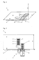
- FIG. 2 shows a schematic plan view of a preferred, first embodiment of an inventive device 1.
- This device comprises in addition to the elements of in FIG. 1 shown working platform a displacement unit 6 with a movable with this displacement along the rail 5 movable support device 9 for transporting objects 2 in the X direction.
- the support device 9 is here designed as a support plate 11 which, together with the displacement unit 6, the tool 7 for characterizing an object 2 and a motor-driven gripping mechanism 8 for grasping and approaching an object 2 to the characterizing tool 7 along the rail 5 is movable ,
- the gripping mechanism 8 become objects 2, be it now carriers (as in Fig. 2 shown), microplates, tube holders, troughs or other container for samples or liquids, pulled on the support plate 11 and transported on this support device 9 in the X direction.
- the bar code reader used here as a characterization tool 7 scans one side of the first microplate 2 and / or one side of the carrier 2 'and thus determines the identity of the samples in the corresponding wells. This identification takes place during which the carrier 2 'is pulled onto the support plate 11 of the support device 9. In accordance with the current X position of this support plate 11, the recorded object can be assigned to its original position on the work surface 4. This detection of the X-position of the support plate 11, the travel of the gripping mechanism 8 for grasping the object (original Y-position of the object) via suitable sensors for detecting linear movements, as these are known in the art from the prior art. The processing of the information from these sensors (not shown in FIG Fig.
- the control of the drives for the movement of the support plate 11 in the X direction and the gripping mechanism 8 in the Y direction, and the assignment of this information to an X / Y-origin position of the object is preferably carried out in a digital computer (not shown) of Part of the Probenmanipuliersystems 3 or this can be provided.
- the in Fig. 2 barcode reader used as a characterization tool 7 simply travels along the rail 5 in a first passage and reads the identification marks or flags of the carriers, which are preferably all substantially vertically readable from the rear.
- This data it is recognized, for example, which types of carriers are involved and whether they can simply be dragged onto the platform surface during subsequent transport.
- a double identification is thus preferably carried out first, and only later (if necessary) is a direct subsequent check performed.
- the gripping mechanism 8 is designed here as a telescopic arm; Alternatively, it can also be designed as an articulated arm.
- Another (not shown) alternative embodiment of the gripping mechanism comprises a running in the Y direction rail with a crawler, which can be raised or lowered, for example, to detect the carrier or deposit.
- the identity of the samples or of the objects is preferably recorded again and the new X / Y position of this object 2, 2 'is stored in the central computer.
- objects 2 can not only be detected using the gripping mechanism 8, transported in a plane and can be deposited again; Rather, objects 2 can also be transported from one level to a plane arranged above or below in the Z direction and deposited there.
- the objects it is advantageous, but not essential, for the objects to be respectively identified with the characterization tool 7 or otherwise characterized.
- FIG. 3 shows a schematic plan view of a second embodiment of an inventive device 1 for characterizing objects 2 in a Probenmanipuliersystem 3, wherein the objects 2 are arranged on at least one, substantially horizontal working field 4 with a longitudinal extent X and a transverse extent Y.
- This device 1 comprises at least one rail 5 extending parallel to the X direction and a displacement unit 6 which can be moved back and forth in the X direction by means of drives on this rail 5, preferably with a tool 7 for characterizing an object 2 and a motor-driven gripping mechanism 8 for grasping and approaching an object 2 to the characterization tool 7.
- the device 1 further comprises a processor for controlling the movements of the displacement unit 6 and the actions of the gripping mechanism 8 as well as for processing the possibly supplied by the characterization tool 7 information.
- the device 1 is characterized in that the displacement unit 6 comprises a support device 9 movable with it along the rail 5 for transporting objects 2 in the X-direction.
- the carrying device 9 comprises a supporting plate 11 designed to carry the objects 2, 2 'and a gripping mechanism 8 for detecting objects 2 at a receiving location, for transporting these objects 2 onto the transporting plate 11 and for depositing these objects 2 at a place of delivery.
- the location in a working field 4 on a first Work platform 14 and the delivery location in a working field 4 'of the first work platform 14 or a second work platform 14' are located.
- the gripping mechanism 8 is extendable in the Y direction over at least the extent of an object 2, 2 'positioned on the working field 4 and designed as a telescopic arm or articulated arm.
- the rail 5 is preferably arranged outside the working field 4 and has a length which corresponds at least to the longitudinal extent X of the working field 4.
- the rail 5 can also be designed to be longer than the working field 4 of the sample manipulation system 3. This makes it possible for objects to be picked up from outside this sample manipulation system 3 and positioned on the working field 4.
- the storage of objects that are to be removed from the working field 4, outside of the sample manipulation system 3 is made possible.
- a device 1 in which the support device 9 with respect to a perpendicular to the horizontal working field 4 Z-axis 10 by an angle ⁇ , which is preferably + 180 ° and / or - 180 °, is rotatable.
- the support device 9 with respect to a perpendicular to the horizontal working field 4 Z-axis 10 by an angle ⁇ , which is preferably + 180 ° and / or - 180 °, is rotatable.
- two Probenmanipuliersysteme 3,3 ' which are arranged parallel to each other and at the same working height (see. Fig. 3 ), with only one device.
- the characterization tool 7 may include a bar code reader and / or an IR thermometer and / or a spectroscope and / or a tube inspection unit and / or a camera.
- the invention also relates to sample manipulation systems 3 with at least one of the devices 1 described so far.
- Such systems can be designed as a single working platform 14 and a single working field 4 or two (or more) substantially horizontal working fields 4, 4 'each having a longitudinal extent X, X 'and each have a transverse extent Y, Y' include.
- more than two work platforms can be combined into a higher-level system.
- the linear arrangement of a larger work platform between two smaller work platforms allows the Setting up a loading station (first smaller work platform) on one narrow side of a large work platform for processing or analyzing samples and setting up an unloading station (second smaller work platform) on the other narrow side of the large work platform (not shown).
- a system for processing samples with high throughput and continuous loading and unloading can be provided.
- a lock can be provided between the smaller and the larger work platform-either on one or both sides-over which objects 2 can preferably be transported by means of the device according to the invention.
- the working fields 4, 4 ' can, however, also be arranged one above the other in parallel or twisted around a virtually arbitrary angle ⁇ (not shown).
- Another combination possibility (not shown) of two working areas 4, 4 ' is that they are placed in two work platforms 14, 14' arranged in parallel one behind the other so that the rear side of the first platform faces the second platform.
- the device 1 according to the invention which in such cases is preferably arranged on the rear side of the second platform, it is then possible to access the front work area through the rear working field 4 '.
- An additional possibility (not shown) of two working areas 4, 4 ' is that they are placed in parallel one behind the other so that the rear side of the first platform faces the front side of the second platform.
- the inventive device 1, which is preferably arranged in such cases on the rear side of the first platform can be accessed without turning on the front and / or rear work platform.
- the displacement unit 6 with the optional characterizing tool 7 and the motor-driven gripping mechanism 8 is then arranged on at least one between the two working fields 4,4 'arranged parallel to the X-direction or X'-direction extending rail 5 by means of drives and movable.
- the displacement unit 6 with the characterizing tool 7 and the motor-driven gripping mechanism 8 can also be arranged to be movable back and forth on two rails 5 (not shown).
- the invention also includes corresponding methods for transporting and preferably also characterizing objects 2 in one or more sample manipulation systems 3, objects 2 being detected at a first X / Y position with the gripping mechanism 8, approximating the characterization tool 7, from this characterization Tool 7 characterized or identified, transported in the X direction and deposited at a second X / Y position again.
- the objects 2 are pulled according to a first embodiment on a plate 11 of a support device 9 and transported on this support plate 11 in the X direction.
- the objects 2 are lifted with a gripping mechanism 8 and transported with this gripping mechanism 8 in the X direction.
- characterization and transport method according to the invention is applied to a system which comprises two or more work fields 4, 4 '
- objects 2, 2' can be detected at a first X / Y position in a first working field 4 and at a second X / Y position in a second working field 4 ', which is preferably parallel to the first working field 4 and disposed above, below or next to this, be deposited. It is also possible to pick up and / or deliver objects 2, 2 'outside of the first or second working field 4, 4'.
- working fields 4,4 ' is the support device 9 - between the detection and deposit of an object 2,2' - with respect to a perpendicular to the horizontal working field 4 Z-axis 10 by an angle ⁇ , preferably + 180 ° and / or - 180 °, rotated.
- a single microplate (as shown) or else an entire carrier with eg three microplates or racks with, for example, 16 sample tubes (both not shown) can be transported from a first working field 4 to a second working field 4 '.
- the tool 7 'for characterizing an object 2, 2' can comprise an IR thermometer and / or a spectroscope and / or a tube inspection unit and / or a camera, so that with these tools the identity and quality of a sample, its chemical Composition or their physical parameters can be detected.
- a tube inspection unit here is a device for carrying out an automatic transmission measurement on samples (eg blood samples in tubes). In this way, the presence, position and quality of samples can be determined with the device according to the invention.
- Standard barcode readers capture a 1-D barcode.
- the characterizing tool 7 is rotatable / tiltable about one or more axes, so that the sample containers or objects 2, 2 'can be observed or detected from different solid angles. Representing the located in virtually any spatial position tilt or rotation axes is a horizontal tilt axis 12 each in the FIGS. 2 to 4 located.
- a variant of a sample manipulation system 3, which is not shown in detail, preferably comprises at least one working field 4, 4 'or a working platform 14, 14', which is configured as a protected area 15, which is inaccessible to persons.
- a protected area 15 may comprise a per se known flow cabinet or a vacuum chamber and possibly present persons before a Protect contamination (bio hazard) by samples to be processed.
- Such a protected area 15 preferably comprises a lock 16, via which objects 2 or samples can be transported into, for example, the flow cabinet or out of it.
- the inventive device 1 can be designed for this purpose as part of this lock 16 or perform their transport function.
- the protected area 15 of a working area can therefore also be separated from the rest of a working platform or a system so that a person can not touch or even damage particularly sensitive parts.
- unintentional misalignment of a multipiped head with, for example, 1536 extremely precisely set pipetting needles
- a high-precision carrier could have a fatal impact, so that the pipetting needles could be damaged by touching the microplate surface.
- contamination or cross-contamination of adjacent samples e.g. to fear in a 1536-microplate.
- Other misalignments could block processes or confuse samples.
Description
Die Erfindung betrifft, gemäss dem Oberbegriff der unabhängigen Ansprüche 1 bzw. 12, ein Probenmanipuliersystem und Verfahren zum Transportieren von Objekten in einem Probenmanipuliersystem, bei welchem die Objekte auf zumindest einem, im wesentlichen horizontalen Arbeitsfeld mit einer Längsausdehnung X und einer Querausdehnung Y angeordnet sind.The invention concerns, according to the preamble of the
Für die Verwendung bei der Untersuchung von Genen ("Genomics"), Proteinen ("Proteomics") zum Entdecken von neuen Wirkstoffen ("Drug Discovery") und in der klinischen Diagnose ("Clinical Diagnostics") sind Vorrichtungen und Systeme bekannt, welche beispielsweise einen Liquid-Handling-Roboter und einen Objekt-Transfer-Roboter umfassen. Ein solches System ist z.B. die vom Anmelder unter dem Namen "Genesis Robotic Sample Processor" vertriebene Arbeitsplattform. Es handelt sich dabei um eine Vorrichtung zum Manipulieren von Proben in Behältern und/oder auf Objektträgern, wobei die Behälter und/oder Objektträger auf einem, im wesentlichen horizontalen Arbeitsfeld mit einer Längsausdehnung X und einer Querausdehnung Y angeordnet sind und wobei die Vorrichtung Robotermanipulatoren zum Manipulieren der Proben umfasst. Dieses Manipulieren kann das Aufnehmen und/oder Abgeben von Fluiden, insbesondere von Flüssigkeiten, z.B. innerhalb dieses X-Y-Feldes betreffen. Ausserdem können Zentrifugen und andere Bearbeitungsstationen oder Analysestationen für Proben, wie Fluoreszenz-Reader und dergleichen vorgesehen sein. Wichtig ist für solche Arbeitsplattformen das Identifizieren von Objekten, wie Probenröhrchen, Mikroplatten und andere Proben enthaltende Behälter. Als Objekte werden hier auch sogenannte "Carrier" bezeichnet, welche üblicherweise zur Aufnahme von drei Mikroplatten ausgebildet sind.For use in genomics, proteomics for drug discovery and in clinical diagnostics, devices and systems are known, including, for example, US Pat a liquid handling robot and an object transfer robot. Such a system is, for example, the working platform sold by the applicant under the name "Genesis Robotic Sample Processor". It is a device for manipulating samples in containers and / or on slides, the containers and / or slides being arranged on a substantially horizontal working field having a longitudinal extent X and a transverse extent Y, and wherein the device manipulates robotic manipulators of the samples. This manipulation may relate to the picking up and / or delivery of fluids, especially liquids, eg within this XY field. In addition, centrifuges and other processing stations or analysis stations for samples such as fluorescence readers and the like may be provided. Important for such work platforms is the identification of objects such as sample tubes, microplates, and other containers containing containers. As objects here also so-called "carriers" are referred to, which are usually designed to accommodate three microplates.
Solche bekannten Arbeitsplattformen umfassen zumindest eine sich parallel zur X-Richtung erstreckende Schiene sowie eine mittels Antrieben an dieser Schiene in X-Richtung hin und her bewegliche Verschiebeeinheit mit einem Werkzeug zum Charakterisieren eines Objekts und einem motorisch angetriebenen Greifmechanismus zum Fassen und Annähern eines Objekts an das Charakterisier-Werkzeug. Ferner umfassen diese Vorrichtung einen Prozessor zum Steuern der Bewegungen der Verschiebeeinheit und der Aktionen des Greifmechanismus sowie zum Verarbeiten der von dem Charakterisier-Werkzeug gelieferten Informationen. Typischerweise ist das Werkzeug in den bekannten Arbeitsplattformen als Barcode-Reader ausgebildet und auf der Verschiebeeinheit angeordnet. Eine solche Anordnung des "Genesis Robotic Sample Processor" (Genesis RSP) ist beispielsweise aus dem Dokument "
Proben, welche bearbeitet bzw. untersucht werden sollen befinden sich üblicherweise in Röhrchen oder in den Wells von Mikroplatten. Solche Röhrchen werden in geeignete Halter gestellt, so dass jeder Halter eine Reihe von Röhrchen aufnehmen kann, welche in Y-Richtung, also in Richtung der Querausdehnung der Arbeitsplattform in einer Linie nebeneinander angeordnet sind. Diese Halter sind auf der Arbeitsfläche geführt verschiebbar. Proben können sich auch in den Wells von Mikroplatten befinden, bzw. aus den Probenröhrchen in diese Wells umpipettiert worden sein. Dabei werden üblicherweise drei Mikroplatten auf einem sogenannten "Carrier" angeordnet, welcher ebenfalls auf der Arbeitsfläche geführt verschiebbar ist.Samples to be processed or examined are usually in tubes or in the wells of microplates. Such tubes are placed in suitable holders, so that each holder can accommodate a series of tubes, which are arranged in the Y-direction, ie in the direction of the transverse extent of the working platform in a line next to each other. These holders are guided on the work surface displaced. Samples may also be in the wells of microplates, or pipetted from the sample tubes into those wells. In this case, usually three microplates are arranged on a so-called "carrier", which is also displaceable guided on the work surface.
Zum Prüfen der Identität der Proben in einem Röhrchenhalter oder auf einem Carrier wird dieser Röhrchenhalter oder Carrier mit einem Greifer erfasst und in den Messbereich des Barcode-Readers gezogen. Nach der Identifikation werden die geprüften Objekte, d.h. der Röhrchenhalter mit den Probenröhrchen bzw. die Carrier mit den Mikroplatten, wieder an ihren ursprünglichen Ort auf der Arbeitsfläche zurückgeschoben.To verify the identity of the samples in a tube holder or on a carrier, this tube holder or carrier is grasped with a gripper and pulled into the measuring range of the barcode reader. After the identification will be the tested objects, ie the tube holder with the sample tubes or the carriers with the micro plates, are pushed back to their original position on the work surface.
Solche Arbeitsplattformen haben sich vielfach bewährt. Allerdings besteht oft die Notwendigkeit, einzelne Röhrchen, Röhrchenhalter, Mikroplatten oder Carrier an eine andere Position auf der Arbeitsfläche bzw. des Arbeitsfeldes der Arbeitsplattform zu transportieren. Üblicherweise geschieht dies von Hand, auf Förderbändern oder auch mit einem Robotermanipulator, der sich zum Beispiel auf den gleichen Schienen fortbewegen kann, wie ein Liquid-Handling-Arm, welcher zum Umpipettieren von Flüssigkeiten verwendet wird.Such work platforms have proven themselves many times. However, there is often a need to transport individual tubes, tube holders, microplates or carriers to a different position on the work surface or working area of the work platform. Usually, this is done by hand, on conveyor belts or with a robot manipulator, which can move, for example, on the same rails, such as a liquid handling arm, which is used for pipetting liquids.
Aus
Es hat sich gezeigt, dass solche Robotermanipulatoren derart häufig eingesetzt werden müssen, dass zum Transportieren von Objekten auf der Arbeitsfläche der Arbeitsplattform oft auf deren Verfügbarkeit gewartet werden muss. Zudem stellt auch die notwendige Identifikation der Proben eine aufwändige Arbeit dar, welche den Betrieb einer solchen Arbeitsplattform verlangsamen kann.It has been found that such robotic manipulators must be used so frequently that the availability of their work often has to be waited for to transport objects on the work surface of the work platform. In addition, the necessary identification of the samples also represents a time-consuming task which can slow down the operation of such a work platform.
Aus dem Dokument
Aus dem Dokument
Auch aus dem Dokument
Aus dem Dokument
Aus dem Dokument
Die Aufgabe der vorliegenden Erfindung besteht gemäss einem ersten Aspekt darin, alternative Vorrichtungen und Verfahren vorzuschlagen, mit denen das Transportieren von Proben in einer Arbeitsplattform rationalisiert werden kann.The object of the present invention according to a first aspect is to propose alternative apparatuses and methods with which the transporting of samples in a work platform can be rationalized.
Gemäss einem zweiten Aspekt betrifft diese Erfindung das zusätzliche Identifizieren bzw. Charakterisieren von Proben in einer Arbeitsplattform.In a second aspect, this invention relates to additional identifying or characterizing samples in a work platform.
Erfindungsgemäss wird die Aufgabe in Bezug auf den ersten Aspekt durch die Merkmalskombinationen der unabhängigen Ansprüche 1 bzw. 12 erfüllt. Zusätzliche erfindungsgemässe Merkmale, Varianten und Verbesserungen ergeben sich aus den abhängigen Ansprüchen.According to the invention, the object is achieved with respect to the first aspect by the feature combinations of
An Hand von schematischen Zeichnungen sollen nun bevorzugte Ausführungsformen der vorliegenden Erfindung näher erläutert werden, ohne dass der Umfang der Erfindung dabei eingeschränkt werden soll. Dabei zeigen:
- Fig. 1
- ein dreidimensionales Schema einer bekannten Arbeitsplattform aus dem Stand der Technik;
- Fig. 2
- eine schematische Draufsicht auf eine erste Ausführungsform einer erfindungsgemässen Vorrichtung;
- Fig. 3
- eine schematische Draufsicht auf eine zweite Ausführungsform einer erfindungsgemässen Vorrichtung;
- Fig. 4
- eine schematische Draufsicht auf eine dritte Ausführungsform einer erfindungsgemässen Vorrichtung.
- Fig. 1
- a three-dimensional scheme of a known working platform from the prior art;
- Fig. 2
- a schematic plan view of a first embodiment of an inventive device;
- Fig. 3
- a schematic plan view of a second embodiment of an inventive device;
- Fig. 4
- a schematic plan view of a third embodiment of an inventive device.
Es ist klar ersichtlich, dass der hier als Charakterisier-Werkzeug 7 eingesetzte Barcode-Reader eine Seite der ersten Mikroplatte 2 und/oder eine Seite des Carriers 2' abtastet und so die Identität der Proben in der entsprechenden Wells feststellt. Diese Identifikation erfolgt während dem der Carrier 2' auf die Tragplatte 11 der Tragvorrichtung 9 gezogen wird. Entsprechend der aktuellen X-Position dieser Tragplatte 11 ist das aufgenommene Objekt seiner ursprünglichen Position auf der Arbeitsfläche 4 zuordenbar. Dieses Erfassen der X-Position der Tragpatte 11, des Verfahrweges des Greifmechanismus 8 zum Fassen des Objekts (ursprüngliche Y-Position des Objekts) erfolgt über geeignete Sensoren zum Erfassen von Linearbewegungen, wie diese dem Fachmann aus dem Stand der Technik bekannt sind. Die Verarbeitung der Informationen dieser Sensoren (nicht gezeigt in
Hersteller und Anwender solcher Arbeitsplattformen haben sich inzwischen an eine hierarchische Gliederung der Objekte gewöhnt, an deren einem Ende die Carrier und an deren anderem Ende die immer einen einzelnen Behälter darstellenden Container stehen. Mehrere Container bilden idealerweise ein zweidimensionales Feld, Array oder Rack beispielsweise in Form einer Mikroplatte. Mehrere (z.B. drei) solcher Racks finden ihre definierte Position auf einem Carrier. Insbesondere, wenn alle Objekte variabel sind, ist das Identifizieren von allen Objekten der ganzen Hierarchie erwünscht und von Vorteil. Es kann auch wichtig sein, einzelne Wells einer Mikroplatte über Softwareanwendungen zu verfolgen. Wegen der definierten Position aller Wells innerhalb eines solchen Objekts genügt es allerdings, die Mikroplatte selbst einwandfrei zu identifizieren. Werden Probenröhrchen als Container oder Behälter verwendet, so sind einzelne dieser Röhrchen praktisch jederzeit auswechselbar (von Hand oder mit Hilfe eines Robotarms) und sollten sicherheitshalber auch individuell identifiziert werden.In the meantime, manufacturers and users of such work platforms have become accustomed to a hierarchical structure of the objects, at one end of which are the carriers and at the other end the containers which always represent a single container. Several containers ideally form a two-dimensional field, array or rack, for example in the form of a microplate. Several (eg three) such racks find their defined position on a carrier. Especially, if all objects are variable, identifying all objects of the entire hierarchy is desirable and beneficial. It may also be important to track individual wells of a microplate through software applications. Because of the defined position of all wells within such an object, however, it is sufficient to identify the microplate itself properly. If sample tubes are used as containers or containers, then individual tubes of this type can be exchanged at any time (by hand or with the help of a robotic arm) and should also be individually identified for safety reasons.
Auch im Rahmen der vorliegenden Erfindung spielt die eben beschriebene Hierarchie eine Rolle: Der in
Der Greifmechanismus 8 ist hier als Teleskoparm ausgebildet; alternativ dazu kann er auch als Gelenkarm ausgebildet sein. Eine weitere (nicht dargestellte) alternative Ausführungsform des Greifmechanismus umfasst eine in Y-Richtung verlaufende Schiene mit einer Raupenkette, welche angehoben bzw. abgesenkt werden kann, um z.B. die Carrier zu erfassen bzw. zu deponieren. Mittels dieser Tragvorrichtung 9 kann ein Objekt 2, welches dem Charakterisier-Werkzeug 7 angenähert wurde, in X-Richtung transportiert werden und darauf mittels des Greifmechanismus 8 an einer Position auf dem Arbeitsfeld deponiert werden, die verschieden ist von der ursprünglichen Position des Objekts auf der Arbeitsfläche.The
Dabei wird beim Ausfahren des Greifmechanismus 8 vorzugsweise die Identität der Proben bzw. der Objekte nochmals erfasst und die neue X/Y-Position dieses Objekts 2,2' im zentralen Rechner gespeichert.During the extension of the
Aus der bisherigen Beschreibung ergibt sich, dass Objekte 2 unter Verwendung des Greifmechanismus 8 nicht nur erfasst, in einer Ebene transportiert und wieder deponiert werden können; vielmehr können auch Objekte 2 von einer Ebene auf eine in Z-Richtung darüber oder darunter angeordnete Ebene transportiert und dort deponiert werden. Beim Ausführen dieser Transportaufgaben ist es vorteilhaft, aber nicht unbedingt erforderlich, dass die Objekte jeweils mit dem Charakterisier-Werkzeug 7 identifiziert oder sonstwie charakterisiert werden.From the previous description it follows that
Bevorzugt ist der Greifmechanismus 8 in Y-Richtung über zumindest die Ausdehnung eines auf dem Arbeitsfeld 4 positionierten Objekts 2,2' ausfahrbar und als Teleskoparm oder Gelenkarm ausgebildet. Zudem ist die Schiene 5 vorzugsweise ausserhalb des Arbeitsfeldes 4 angeordnet und weist eine Länge auf, welche zumindest der Längsausdehnung X des Arbeitsfeldes 4 entspricht. Die Schiene 5 kann aber auch länger als das Arbeitsfeld 4 des Probenmanipuliersystems 3 ausgebildet sein. Dadurch wird ermöglicht, dass Objekte von ausserhalb dieses Probenmanipuliersystems 3 abgeholt und auf dem Arbeitsfeld 4 positioniert werden können. Zudem wird auch die Ablage von Objekten, die von dem Arbeitsfeld 4 entfernt werden sollen, ausserhalb des Probenmanipuliersystems 3 ermöglicht. Besonders bevorzugt ist eine Vorrichtung 1, bei welcher die Tragvorrichtung 9 in Bezug auf eine senkrecht zum horizontalen Arbeitsfeld 4 stehenden Z-Achse 10 um einen Winkel β, der vorzugsweise + 180° und/oder - 180 ° beträgt, drehbar ist. In diesem Falle können zwei Probenmanipuliersysteme 3,3', welche parallel zu einander und auf der gleichen Arbeitshöhe angeordnet sind (vgl.
Die Erfindung betrifft auch Probenmanipuliersysteme 3 mit zumindest einer der bisher beschriebenen Vorrichtungen 1. Solche Systeme können als eine einzige Arbeitsplattform 14 ausgebildet sein und ein einziges Arbeitsfeld 4 oder zwei (oder mehr) im wesentlichen horizontale Arbeitsfelder 4,4' mit je einer Längsausdehnung X,X' und je einer Querausdehnung Y,Y' umfassen. Dabei sind diese Arbeitsfelder 4,4' vorzugsweise in einer Ebene und parallel zueinander angeordnet. Dabei kommt eine besonders Platz sparende, spiegelsymmetrische Anordnung der Arbeitsfelder 4,4' wie in
The invention also relates to sample
Zudem können mehr als zwei Arbeitsplattformen zu einem übergeordneten System zusammengefasst werden. Insbesondere das lineare Anordnen einer grösseren Arbeitspattform zwischen zwei kleineren Arbeitsplattformen ermöglicht das Einrichten einer Beladestation (erste kleinere Arbeitsplattform) an der einen Schmalseite einer grossen Arbeitsplattform zum Bearbeiten bzw. Analysieren von Proben und das Einrichten einer Entladestation (zweite kleinere Arbeitsplattform) an der anderen Schmalseite der grossen Arbeitsplattform (nicht gezeigt). Mit dieser bevorzugten Anordnung kann ein System zum Bearbeiten von Proben mit hohem Durchsatz und einem kontinuierlichen Be- bzw. Entladen geschaffen werden. Falls erwünscht, kann zwischen den kleineren und der grossen Arbeitsplattform - entweder auf einer oder auf beiden Seiten - eine Schleuse vorgesehen sein, über welche Objekte 2 bevorzugt mittels der erfindungsgemässen Vorrichtung transportiert werden können.In addition, more than two work platforms can be combined into a higher-level system. In particular, the linear arrangement of a larger work platform between two smaller work platforms allows the Setting up a loading station (first smaller work platform) on one narrow side of a large work platform for processing or analyzing samples and setting up an unloading station (second smaller work platform) on the other narrow side of the large work platform (not shown). With this preferred arrangement, a system for processing samples with high throughput and continuous loading and unloading can be provided. If desired, a lock can be provided between the smaller and the larger work platform-either on one or both sides-over which objects 2 can preferably be transported by means of the device according to the invention.
Die Arbeitsfelder 4,4' können aber auch zueinander parallel oder um einen praktisch beliebigen Winkel β verdreht übereinander angeordnet sein (nicht gezeigt). Eine weitere (nicht gezeigte) Kombinationsmöglichkeit von zwei Arbeitsfeldern 4,4' besteht darin, dass diese in zwei parallel hintereinander angeordneten Arbeitsplattformen 14,14' platziert werden, so dass die Hinterseite der ersten Plattform der Vorderseite der zweiten Plattform gegenüber steht. Mit der erfindungsgemässen Vorrichtung 1, die in solchen Fällen vorzugsweise an der Hinterseite der zweiten Plattform angeordnet ist, kann dann "durch das hintere Arbeitsfeld 4' hindurch" auf das vordere Arbeitsfeld zugegriffen werden. Eine zusätzliche (nicht gezeigte) Kombinationsmöglichkeit von zwei Arbeitsfeldern 4,4' besteht darin, dass diese parallel hintereinander platziert werden, so dass die Hinterseite der ersten Plattform der Vorderseite der zweiten Plattform gegenüber steht. Mit der erfindungsgemässen Vorrichtung 1, die in solchen Fällen vorzugsweise an der Hinterseite der ersten Plattform angeordnet ist, kann ohne Drehen auf die vordere und/oder hintere Arbeitsplattform zugegriffen werden.The working
Die Verschiebeeinheit 6 mit dem optionalen Charakterisier-Werkzeug 7 und dem motorisch angetriebenen Greifmechanismus 8 ist dann an zumindest einer zwischen den beiden Arbeitsfeldern 4,4' angeordneten, sich parallel zur X-Richtung bzw. X'-Richtung erstreckenden Schiene 5 mittels Antrieben hin und her beweglich. Die Verschiebeeinheit 6 mit dem Charakterisier-Werkzeug 7 und dem motorisch angetriebenen Greifmechanismus 8 kann auch an zwei Schienen 5 (nicht gezeigt) hin und her beweglich angeordnet sein.The
Die Erfindung umfasst auch entsprechende Verfahren zum Transportieren und vorzugsweise auch zum Charakterisieren von Objekten 2 in einem oder mehreren Probenmanipuliersystemen 3, wobei Objekte 2 an einer ersten X/Y-Position mit dem Greifmechanismus 8 erfasst, dem Charakterisier-Werkzeug 7 angenähert, von diesem Charakterisier-Werkzeug 7 charakterisiert bzw. identifiziert, in X-Richtung transportiert und an einer zweiten X/Y-Position wieder deponiert werden. Zu diesem Zweck werden die Objekte 2 gemäss einer ersten Ausführungsform auf eine Platte 11 einer Tragvorrichtung 9 gezogen und auf dieser Tragplatte 11 in X-Richtung transportiert. Gemäss einer zweiten Ausführungsform werden die Objekte 2 mit einem Greifmechanismus 8 angehoben und mit diesem Greifmechanismus 8 in X-Richtung transportiert. Wird das erfindungsgemässe Charakterisier- und Transport-Verfahren an einem System angewendet, welches zwei oder mehr Arbeitsfelder 4,4' umfasst, so können Objekte 2,2' an einer ersten X/Y-Position in einem ersten Arbeitsfeld 4 erfasst und an einer zweiten X/Y-Position in einem zweiten Arbeitsfeld 4', welches vorzugsweise parallel zum ersten Arbeitsfeld 4 und über, unter oder neben diesem angeordnet ist, deponiert werden. Auch können Objekte 2,2' ausserhalb des ersten oder zweiten Arbeitsfeldes 4,4' aufgenommen und/oder abgegeben werden.The invention also includes corresponding methods for transporting and preferably also characterizing
Zum Ausführen des Verfahrens in einem Probenmanipuliersystem 3 mit gemäss
Alternativ zu der Darstellung in den gezeigten Figuren kann das Werkzeug 7 zum Charakterisieren eines Objekts 2,2' ein IR-Thermometer und/oder ein Spektroskop und/oder eine Tube Inspection Unit und/oder eine Kamera umfassen, so dass mit diesen Werkzeugen die Identität und Qualität einer Probe, deren chemische Zusammensetzung bzw. deren physikalische Parameter erfasst werden können. Als Tube Inspection Unit wird hier eine Vorrichtung zum Durchführen einer automatischen Transmissionsmessung an Proben (z.B. Blutproben in Röhrchen) bezeichnet. Auf diese Weise kann mit der erfindungsgemässen Vorrichtung die Anwesenheit, die Position und die Qualität von Proben festgestellt werden. Übliche Barcode-Reader erfassen einen 1-D-Strichcode. Es können aber auch solche Reader eingesetzt werden, die einen 2-D-Code (z.B. in Form einer Pixelfläche) oder einen 3-D-Code (z.B. in Form eines Reliefs oder einer Holografie) lesen. Das Charakterisierwerkzeug 7 ist um eine oder mehrere Achsen dreh/kippbar, so dass die Probenbehälter bzw. Objekte 2,2' aus unterschiedlichen Raumwinkeln beobachtet oder erfasst werden können. Stellvertretend für die sich in praktisch beliebiger Raumlage befindenden Kipp- oder Drehachsen ist eine horizontale Kippachse 12 jeweils in den
Alle Figuren zeigen nur eine Vorrichtung 1, es kann aber - vor allem wenn mehrere Arbeitsfelder 4,4' versorgt werden müssen - vorteilhaft sein, dass das System zwei oder mehr Vorrichtungen 1 zum Transportieren und allfälligen Charakterisieren von Objekten 2 umfasst.All figures show only one
Die Bezugszeichen in den
Eine nicht näher dargestellte Variante eines Probenmanipuliersystems 3 umfasst vorzugsweise zumindest ein Arbeitsfeld 4,4' oder eine Arbeitsplattform 14,14', die als für Personen unzugänglicher, geschützter Bereich 15 ausgestaltet ist. Ein solcher geschützter Bereich 15 kann ein an sich bekanntes Flow Cabinet oder eine Unterdruckkammer umfassen und allenfalls anwesende Personen vor einer Kontamination (Bio Hazard) durch zu verarbeitende Proben schützen. Vorzugsweise umfasst ein derartiger geschützter Bereich 15 eine Schleuse 16, über welche Objekte 2 oder Proben in z.B. das Flow Cabinet hinein oder aus diesem heraus transportiert werden können. Die erfindungsgemässe Vorrichtung 1 kann zu diesem Zweck als Teil dieser Schleuse 16 ausgebildet sein bzw. deren Transportfunktion ausführen.A variant of a
Der geschützte Bereich 15 eines Arbeitsfeldes kann aber auch deshalb vom Rest einer Arbeitsplattform oder eines Systems abgetrennt sein, damit eine Person nicht besonders empfindliche Teile berühren oder gar beschädigen kann. Beispielsweise könnte sich ein unbeabsichtigtes Dejustieren eines Multipipettenkopfes (mit z.B. 1536 extrem genau eingestellten Pipettiernadeln) oder auch ein nur geringfügiges Verschieben eines hochpräzisen Carriers fatal auswirken, so dass die Pipettiernadeln durch Berühren der Mikroplattenoberfläche beschädigt werden könnten. Zudem wäre eine Kontamination oder Kreuzkontamination von benachbarten Proben z.B. in einer 1536-er Mikroplatte zu befürchten. Andere Dejustierungen könnten ein Blockieren von Verfahrensabläufen bewirken oder zum Verwechseln von Proben beitragen.However, the protected area 15 of a working area can therefore also be separated from the rest of a working platform or a system so that a person can not touch or even damage particularly sensitive parts. For example, unintentional misalignment of a multipiped head (with, for example, 1536 extremely precisely set pipetting needles), or even a slight shift of a high-precision carrier, could have a fatal impact, so that the pipetting needles could be damaged by touching the microplate surface. In addition, contamination or cross-contamination of adjacent samples, e.g. to fear in a 1536-microplate. Other misalignments could block processes or confuse samples.
Claims (17)
- Sample manipulation system (3), which comprises:a) an essentially horizontal working field (4) having a longitudinal extension in the X direction and a transverse extension in the Y direction extending essentially perpendicular thereto,b) at least one device (1) for transporting objects (2), which are either containers for samples or liquids or carriers for these containers, and which are arranged on the at least one horizontal working field (4), wherein the device (1) comprises at least one rail (5) extending parallel to the X direction and also a displacement unit (6), which is movable back and forth in the X direction on this rail (5) by means of drives, having a gripping mechanism (8) driven by a motor in the Y direction for grasping an object (2) and for approaching this object (2) to a characterization tool (7),c) a characterization tool (7), which is implemented as a barcode reader having a measuring range, and which is arranged on the displacement unit (6), wherein the barcode reader is capable of simply traveling along the rail (5) in a first passage and reading the identification marks or flags of the carrier, andd) a processor for controlling the movements of the displacement unit (6) and the actions of the gripping mechanism (8) and for processing the items of information delivered by the barcode reader,characterized in that the displacement unit (6) comprises a support device (9), which is movable together with it along the rail (5), for transporting objects (2) in the X direction, wherein this support device (9) is implemented as a plate (11) for supporting objects (2) drawn using the gripping mechanism (8) onto this support plate (11),
and in that the barcode reader is implemented as rotatable/tiltable around one or more axes for capturing objects (2) from different spatial angles, so that it is capable in a second passage, while a carrier is drawn by means of the gripping mechanism (8) onto the support plate (11) and into the measuring range of the barcode reader, of checking the identity of the samples in the carrier. - Sample manipulation system (3) according to Claim 1, characterized in that the support plate (11) is rotatable together with the gripping mechanism (8) in relation to a Z axis (10), which is perpendicular to the horizontal working field (4), by an angle (β), which is preferably +180° and/or -180°.
- Sample manipulation system (3) according to one of the preceding claims, characterized in that the rail (5) is arranged outside the working field (4) and has a length which corresponds at least to the longitudinal extension in the X direction of the working field (4).
- Sample manipulation system (3) according to one of the preceding claims, characterized in that the gripping mechanism (8) is extendable in the Y direction over at least the extension of an object (2,2') positioned on the working field (4) and is implemented as a telescopic arm, jointed arm, or caterpillar track.
- Sample manipulation system (3) according to one of the preceding claims, characterized in that the device (1) for transporting objects (2) comprises a tool (7) for characterizing objects (2), wherein the motor-driven gripping mechanism (8) is implemented to grasp and approach an object (2) to this characterization tool (7) and the processor for controlling the movements of the displacement unit (6) and the actions of the gripping mechanism (8) is also implemented to process items of information delivered by this characterization tool (7).
- Sample manipulation system (3) according to Claim 5, characterized in that the characterization tool (7) comprises an IR thermometer and/or a spectroscope and/or a tube inspection unit and/or a camera.
- Sample manipulation system (3) according to one of the preceding claims, characterized in that the barcode reader is implemented to read a 1-D, 2-D, or 3-D code.
- Sample manipulation system (3) according to one of the preceding claims, which comprises two or more substantially horizontal working fields (4,4'), characterized in that the displacement unit (6), with the support plate (11) and the motor-driven gripping mechanism (8), is movable by means of drives back and forth on at least one rail (5), which is arranged behind these working fields (4,4') and extends parallel to the X direction or X' direction.
- Sample manipulation system (3) according to Claim 8, characterized in that these working fields (4,4') are arranged identically aligned adjacent to one another and/or mirror-symmetrically aligned one behind the other.
- Sample manipulation system (3) according to Claim 8 or 9, characterized in that these working fields (4,4') are arranged parallel to one another.
- The sample manipulation system (3) according to one of the Claims 8 to 10, characterized in that these working fields (4,4') are all arranged in one plane.
- Method for identifying and transporting objects (2) in a sample manipulation system (3), which comprises:a) providing a substantially horizontal working field (4) having a longitudinal extension in the X direction and a transverse extension in the Y direction extending substantially perpendicularly thereto, wherein the objects (2) are arranged on this working field (4),b) providing a device (1) for transporting the objects (2), which are either containers for samples or liquids or carriers for these containers, wherein this device (1) comprises at least one rail (5) extending parallel to the X direction and also a displacement unit (6), which is movable back and forth in the X direction by means of drives on this rail (5), having a gripping mechanism (8) driven by a motor in the Y direction for grasping an object (2) and for approaching this object (2) to a characterization tool (7),c) providing a characterization tool (7), which is implemented as a barcode reader having a measuring range, and which is arranged on the displacement unit (6), andd) providing a processor for controlling the movements of the displacement unit (6) and the actions of the gripping mechanism (8) and also for processing the items of information delivered by the barcode reader,wherein the barcode reader travels in a first passage simply along the rail (5) and reads the identification marks or flags of the carrier, characterized in that objects (2) are acquired at a first X/Y position using the gripping mechanism (8), drawn onto a plate (11) of a support device (9), transported on this support plate (11) in the X direction and deposited again at a second X/Y position,
and in that the barcode reader is rotated/tilted around one or more axes so that, to capture objects (2) from various spatial angles in a second passage, while a carrier is drawn by means of the gripping mechanism (8) onto the support plate (11) and into the measuring range of the barcode reader, it checks the identity of the samples in the carrier. - Method according to Claim 12, characterized in that an object (2) is acquired at a first X/Y position in a first working field (4) using the device (1) and is deposited at a second X/Y position in a second working field (4'), which is arranged parallel to the first working field (4), or above, below, or adjacent thereto, respectively.
- Method according to Claim 13, characterized in that the object (2) is acquired and/or deposited outside the first or second working field (4,4').
- Method according to one of the Claims 12 to 14, characterized in that the support device (9) is rotated - between the acquiring and depositing of an object (2) - in relation to a Z axis (10), which is perpendicular to the horizontal working field (4), by an angle (β), which is preferably +180° and/or -180°.
- Method according to one of the Claims 12 to 15, characterized in that the objects (2) are approached using the device (1) to a tool (7) for characterizing an object (2) and are characterized by this characterization tool (7), wherein the items of information delivered by the characterization tool (7) are processed by a processor of the device (1).
- Method according to Claim 16, characterized in that the chemical composition and/or physical properties of samples is/are established using the characterization tool (7).
Applications Claiming Priority (2)
| Application Number | Priority Date | Filing Date | Title |
|---|---|---|---|
| CH12172003 | 2003-07-11 | ||
| CH12172003 | 2003-07-11 |
Publications (3)
| Publication Number | Publication Date |
|---|---|
| EP1496365A2 EP1496365A2 (en) | 2005-01-12 |
| EP1496365A3 EP1496365A3 (en) | 2012-02-01 |
| EP1496365B1 true EP1496365B1 (en) | 2014-06-04 |
Family
ID=33438120
Family Applications (1)
| Application Number | Title | Priority Date | Filing Date |
|---|---|---|---|
| EP04015100.3A Active EP1496365B1 (en) | 2003-07-11 | 2004-06-28 | Device and method for transporting objects |
Country Status (3)
| Country | Link |
|---|---|
| US (1) | US7264432B2 (en) |
| EP (1) | EP1496365B1 (en) |
| JP (1) | JP4430996B2 (en) |
Families Citing this family (20)
| Publication number | Priority date | Publication date | Assignee | Title |
|---|---|---|---|---|
| WO2006098039A1 (en) * | 2005-03-15 | 2006-09-21 | Hirata Corporation | Work handling device |
| US20080003092A1 (en) * | 2006-06-30 | 2008-01-03 | Petar Baclija | Rotary union connection |
| JP4875951B2 (en) * | 2006-08-31 | 2012-02-15 | Juki株式会社 | Automatic dispenser and its sample supply installation stand |
| DE102006049208A1 (en) * | 2006-10-18 | 2008-04-24 | Polysius Ag | Labor system for processing and analyzing samples of e.g. cement production, has application device provided for applying samples within area of conditioning mechanisms, and movable between conditioning mechanisms |
| US20100233754A1 (en) * | 2007-08-15 | 2010-09-16 | Christophe Alain Guex | Vessel Transporting Apparatus and Method |
| EP2148205B1 (en) * | 2008-07-25 | 2013-01-02 | F. Hoffmann-La Roche AG | A method and laboratory system for handling sample tubes and an image analysing unit |
| EP2148206B1 (en) * | 2008-07-25 | 2015-11-18 | F.Hoffmann-La Roche Ag | A laboratory system for handling sample tube racks, an alignmemt element for sample tube racks and a rack tray receiver assembly |
| ES2402227T3 (en) * | 2008-07-25 | 2013-04-29 | F. Hoffmann-La Roche Ag | A storage and recovery laboratory system and a method for handling laboratory sample tubes |
| ES2582205T3 (en) | 2008-07-25 | 2016-09-09 | F. Hoffmann-La Roche Ag | Laboratory method and system for handling sample tube racks |
| AU2012305682B2 (en) | 2011-09-09 | 2015-08-13 | Gen-Probe Incorporated | Automated sample handling instrumentation, systems, processes, and methods |
| JP6082018B2 (en) * | 2011-11-07 | 2017-02-15 | ベックマン コールター, インコーポレイテッド | System and method for processing samples |
| WO2014059134A1 (en) * | 2012-10-11 | 2014-04-17 | Siemens Healthcare Diagnostics Inc. | Automation maintenance carrier |
| DE102012020679B4 (en) * | 2012-10-22 | 2022-01-05 | Grenzebach Maschinenbau Gmbh | Method and device for the rapid relocation of panels |
| AU2013202805B2 (en) * | 2013-03-14 | 2015-07-16 | Gen-Probe Incorporated | System and method for extending the capabilities of a diagnostic analyzer |
| CN103884856B (en) * | 2014-04-01 | 2015-06-10 | 重庆科斯迈生物科技有限公司 | Cup strip conveying system of chemiluminescence immunoassay analyzer |
| EP3199953B1 (en) | 2016-02-01 | 2021-03-24 | Roche Diagniostics GmbH | Method for teaching positioning of a bar code scanner and apparatus for processing a sample or reagent |
| CN107271705B (en) * | 2017-06-30 | 2018-10-16 | 江南大学 | A kind of high throughput screening system of production line formula |
| CN108482925B (en) * | 2018-02-28 | 2019-02-22 | 中国烟草总公司北京市公司物流中心 | A kind of working area management method |
| CN110018320A (en) * | 2019-03-29 | 2019-07-16 | 赫安仕科技(苏州)有限公司 | A kind of detection driving device and driving method |
| CN112249579A (en) * | 2020-10-23 | 2021-01-22 | 南京晓庄学院 | Differential distributed control type automatic dispensing device for traditional Chinese medicine |
Citations (2)
| Publication number | Priority date | Publication date | Assignee | Title |
|---|---|---|---|---|
| EP0317325A2 (en) * | 1987-11-20 | 1989-05-24 | Hewlett-Packard Company | Forensic sample tracking system and print station therefor |
| EP1248170A1 (en) * | 2001-04-05 | 2002-10-09 | Inpeco S.r.l. | Method for the management of workcell systems based on an automation management system |
Family Cites Families (8)
| Publication number | Priority date | Publication date | Assignee | Title |
|---|---|---|---|---|
| US5388946A (en) | 1988-01-20 | 1995-02-14 | Grau Gmbh & Co. | Systems and methods for the automated archiving and retrieval of computer data storage cassettes |
| AU2193492A (en) | 1991-06-13 | 1993-01-12 | Abbott Laboratories | Automated specimen analyzing apparatus and method |
| US5125150A (en) * | 1991-09-03 | 1992-06-30 | Amp Incorporated | Tool for mass terminating wires to electrical connectors |
| EP0629858A1 (en) * | 1993-06-16 | 1994-12-21 | Kabushiki Kaisha Nittec | Sample preparation apparatus |
| EP0909389A2 (en) | 1996-07-05 | 1999-04-21 | Beckman Coulter, Inc. | Automated sample processing system |
| US6739448B1 (en) | 2000-02-01 | 2004-05-25 | Incyte Corporation | Method and apparatus for shuttling microtitre plates |
| JP2002060011A (en) * | 2000-08-11 | 2002-02-26 | Murata Mach Ltd | Automated warehouse |
| US6923612B2 (en) * | 2002-03-29 | 2005-08-02 | TGW Transportgeräte GmbH & Co. KG | Load-handling system and telescopic arm therefor |
-
2004
- 2004-06-28 EP EP04015100.3A patent/EP1496365B1/en active Active
- 2004-07-08 US US10/886,887 patent/US7264432B2/en active Active
- 2004-07-09 JP JP2004203123A patent/JP4430996B2/en active Active
Patent Citations (2)
| Publication number | Priority date | Publication date | Assignee | Title |
|---|---|---|---|---|
| EP0317325A2 (en) * | 1987-11-20 | 1989-05-24 | Hewlett-Packard Company | Forensic sample tracking system and print station therefor |
| EP1248170A1 (en) * | 2001-04-05 | 2002-10-09 | Inpeco S.r.l. | Method for the management of workcell systems based on an automation management system |
Non-Patent Citations (1)
| Title |
|---|
| TECAN: "Genesis RSP and genesis NPS Instruments Operating Manual - Doc ID 390783 V2.6", October 2001 (2001-10-01), pages 3/11 - 3/15, XP055084535 * |
Also Published As
| Publication number | Publication date |
|---|---|
| EP1496365A3 (en) | 2012-02-01 |
| JP2005031087A (en) | 2005-02-03 |
| US7264432B2 (en) | 2007-09-04 |
| EP1496365A2 (en) | 2005-01-12 |
| US20050053454A1 (en) | 2005-03-10 |
| JP4430996B2 (en) | 2010-03-10 |
Similar Documents
| Publication | Publication Date | Title |
|---|---|---|
| EP1496365B1 (en) | Device and method for transporting objects | |
| DE60210946T2 (en) | GRIPPING MECHANISM, DEVICE AND METHOD | |
| EP1759215B1 (en) | Device and method for disposing pipette tips or dispenser tips in a system used for manipulating liquid samples | |
| EP2027926B1 (en) | Apparatus for processing biological material | |
| DE69835795T2 (en) | Device for the automatic performance of laboratory tests | |
| DE60115860T2 (en) | MICROARRAY DOSING DEVICES WITH SENSORS | |
| DE102008022835B3 (en) | analyzer | |
| DE112010000822B4 (en) | Automatic analysis device and automatic analysis method | |
| DE3736632C2 (en) | Automated device for analyzing patient samples | |
| EP1733239B1 (en) | Device and method for identifying, locating and tracking objects on laboratory equipment | |
| EP2696205B1 (en) | Microplate reader with lid lifter for microplates | |
| DE60208381T2 (en) | SAMPLE ENTER THE PURITY | |
| EP2730927A1 (en) | Reagent station for an automatic analyzer | |
| WO2002058850A1 (en) | Holding device | |
| EP2702386B1 (en) | Punching device with gripping unit | |
| DE102020102758B4 (en) | Method and system for automated germ monitoring in an isolator | |
| DE60012752T2 (en) | FLEXIBLE PIPETTE STRIP AND RELATED APPLICATION METHOD | |
| EP3436832B1 (en) | Conveying device | |
| DE10017802A1 (en) | Laboratory robot, useful for automated isolation of nucleic acid, includes orientation device to ensure proper alignment between robotic arm and unit being transported | |
| EP3666381B1 (en) | Laboratory device for automatic treatment of laboratory samples | |
| WO2017001676A1 (en) | Pipetting apparatus with image processing | |
| WO2020114873A1 (en) | Automatable temperature-control apparatus | |
| WO2013064237A2 (en) | Automatic structure determination | |
| CH696030A5 (en) | Apparatus and their use for the manipulation of samples. | |
| WO2001077689A1 (en) | Device for implementing chemical or biological methods |
Legal Events
| Date | Code | Title | Description |
|---|---|---|---|
| PUAI | Public reference made under article 153(3) epc to a published international application that has entered the european phase |
Free format text: ORIGINAL CODE: 0009012 |
|
| AK | Designated contracting states |
Kind code of ref document: A2 Designated state(s): AT BE BG CH CY CZ DE DK EE ES FI FR GB GR HU IE IT LI LU MC NL PL PT RO SE SI SK TR |
|
| AX | Request for extension of the european patent |
Extension state: AL HR LT LV MK |
|
| PUAL | Search report despatched |
Free format text: ORIGINAL CODE: 0009013 |
|
| RIC1 | Information provided on ipc code assigned before grant |
Ipc: B65G 1/04 20060101ALI20111219BHEP Ipc: G01N 35/00 20060101AFI20111219BHEP Ipc: G01N 35/02 20060101ALI20111219BHEP Ipc: G01N 35/04 20060101ALI20111219BHEP |
|
| AK | Designated contracting states |
Kind code of ref document: A3 Designated state(s): AT BE BG CH CY CZ DE DK EE ES FI FR GB GR HU IE IT LI LU MC NL PL PT RO SE SI SK TR |
|
| AX | Request for extension of the european patent |
Extension state: AL HR LT LV MK |
|
| RIC1 | Information provided on ipc code assigned before grant |
Ipc: G01N 35/02 20060101ALI20111223BHEP Ipc: G01N 35/00 20060101AFI20111223BHEP Ipc: B65G 1/04 20060101ALI20111223BHEP Ipc: G01N 35/04 20060101ALI20111223BHEP |
|
| 17P | Request for examination filed |
Effective date: 20120614 |
|
| AKX | Designation fees paid |
Designated state(s): CH DE FR GB LI |
|
| 17Q | First examination report despatched |
Effective date: 20120921 |
|
| GRAP | Despatch of communication of intention to grant a patent |
Free format text: ORIGINAL CODE: EPIDOSNIGR1 |
|
| INTG | Intention to grant announced |
Effective date: 20140102 |
|
| GRAS | Grant fee paid |
Free format text: ORIGINAL CODE: EPIDOSNIGR3 |
|
| GRAA | (expected) grant |
Free format text: ORIGINAL CODE: 0009210 |
|
| RIN1 | Information on inventor provided before grant (corrected) |
Inventor name: OBERHOLZER, ALOIS Inventor name: MUERSET, PETER Inventor name: SCHINZEL, FRED Inventor name: ROMER, HANSPETER Inventor name: BATLINER, GREGOR Inventor name: WIGGLI, MARKUS |
|
| AK | Designated contracting states |
Kind code of ref document: B1 Designated state(s): CH DE FR GB LI |
|
| REG | Reference to a national code |
Ref country code: GB Ref legal event code: FG4D Free format text: NOT ENGLISH |
|
| RIN2 | Information on inventor provided after grant (corrected) |
Inventor name: ROMER, HANSPETER Inventor name: OBERHOLZER, ALOIS Inventor name: SCHINZEL, FRED Inventor name: MUERSET, PETER Inventor name: WIGGLI, MARKUS Inventor name: BATLINER, GREGOR |
|
| REG | Reference to a national code |
Ref country code: CH Ref legal event code: EP |
|
| REG | Reference to a national code |
Ref country code: DE Ref legal event code: R096 Ref document number: 502004014627 Country of ref document: DE Effective date: 20140710 |
|
| REG | Reference to a national code |
Ref country code: CH Ref legal event code: NV Representative=s name: OK PAT AG PATENTE MARKEN LIZENZEN, CH |
|
| REG | Reference to a national code |
Ref country code: DE Ref legal event code: R097 Ref document number: 502004014627 Country of ref document: DE |
|
| PLBE | No opposition filed within time limit |
Free format text: ORIGINAL CODE: 0009261 |
|
| STAA | Information on the status of an ep patent application or granted ep patent |
Free format text: STATUS: NO OPPOSITION FILED WITHIN TIME LIMIT |
|
| 26N | No opposition filed |
Effective date: 20150305 |
|
| REG | Reference to a national code |
Ref country code: DE Ref legal event code: R097 Ref document number: 502004014627 Country of ref document: DE Effective date: 20150305 |
|
| REG | Reference to a national code |
Ref country code: FR Ref legal event code: PLFP Year of fee payment: 13 |
|
| REG | Reference to a national code |
Ref country code: FR Ref legal event code: PLFP Year of fee payment: 14 |
|
| REG | Reference to a national code |
Ref country code: FR Ref legal event code: PLFP Year of fee payment: 15 |
|
| REG | Reference to a national code |
Ref country code: CH Ref legal event code: PFUS Owner name: TECAN TRADING AG, CH Free format text: FORMER OWNER: TECAN TRADING AG, CH |
|
| PGFP | Annual fee paid to national office [announced via postgrant information from national office to epo] |
Ref country code: FR Payment date: 20230510 Year of fee payment: 20 Ref country code: DE Payment date: 20230502 Year of fee payment: 20 |
|
| PGFP | Annual fee paid to national office [announced via postgrant information from national office to epo] |
Ref country code: GB Payment date: 20230504 Year of fee payment: 20 Ref country code: CH Payment date: 20230702 Year of fee payment: 20 |