EP2148208B1 - Method and laboratory system for handling sample tube racks - Google Patents
Method and laboratory system for handling sample tube racks Download PDFInfo
- Publication number
- EP2148208B1 EP2148208B1 EP09009330.3A EP09009330A EP2148208B1 EP 2148208 B1 EP2148208 B1 EP 2148208B1 EP 09009330 A EP09009330 A EP 09009330A EP 2148208 B1 EP2148208 B1 EP 2148208B1
- Authority
- EP
- European Patent Office
- Prior art keywords
- storage
- storage rack
- rack
- transfer system
- racks
- Prior art date
- Legal status (The legal status is an assumption and is not a legal conclusion. Google has not performed a legal analysis and makes no representation as to the accuracy of the status listed.)
- Active
Links
- 238000000034 method Methods 0.000 title claims description 20
- 238000003860 storage Methods 0.000 claims description 253
- 239000000523 sample Substances 0.000 claims description 75
- 238000012546 transfer Methods 0.000 claims description 53
- 239000002699 waste material Substances 0.000 claims description 28
- 230000008878 coupling Effects 0.000 claims description 7
- 238000010168 coupling process Methods 0.000 claims description 7
- 238000005859 coupling reaction Methods 0.000 claims description 7
- 230000005484 gravity Effects 0.000 claims description 5
- 239000006101 laboratory sample Substances 0.000 claims description 5
- 238000003032 molecular docking Methods 0.000 description 16
- 238000012360 testing method Methods 0.000 description 11
- 238000012545 processing Methods 0.000 description 6
- 230000032258 transport Effects 0.000 description 6
- 230000007246 mechanism Effects 0.000 description 5
- 239000000969 carrier Substances 0.000 description 4
- 238000005192 partition Methods 0.000 description 4
- 238000004590 computer program Methods 0.000 description 3
- 238000004458 analytical method Methods 0.000 description 2
- 238000006073 displacement reaction Methods 0.000 description 2
- 230000000694 effects Effects 0.000 description 2
- 230000007935 neutral effect Effects 0.000 description 2
- 230000008569 process Effects 0.000 description 2
- 241000282414 Homo sapiens Species 0.000 description 1
- 238000004026 adhesive bonding Methods 0.000 description 1
- 230000004888 barrier function Effects 0.000 description 1
- 230000008901 benefit Effects 0.000 description 1
- 239000012620 biological material Substances 0.000 description 1
- 239000008280 blood Substances 0.000 description 1
- 210000004369 blood Anatomy 0.000 description 1
- 239000003153 chemical reaction reagent Substances 0.000 description 1
- 230000000295 complement effect Effects 0.000 description 1
- 238000000151 deposition Methods 0.000 description 1
- 238000003745 diagnosis Methods 0.000 description 1
- 238000007876 drug discovery Methods 0.000 description 1
- 238000005516 engineering process Methods 0.000 description 1
- 238000010191 image analysis Methods 0.000 description 1
- 238000000338 in vitro Methods 0.000 description 1
- 238000013101 initial test Methods 0.000 description 1
- 238000003780 insertion Methods 0.000 description 1
- 230000037431 insertion Effects 0.000 description 1
- 239000002184 metal Substances 0.000 description 1
- 230000003287 optical effect Effects 0.000 description 1
- 239000013610 patient sample Substances 0.000 description 1
- 238000002360 preparation method Methods 0.000 description 1
- 230000004044 response Effects 0.000 description 1
- 238000005496 tempering Methods 0.000 description 1
- 210000002700 urine Anatomy 0.000 description 1
- 230000000007 visual effect Effects 0.000 description 1
- 238000003466 welding Methods 0.000 description 1
Images


Classifications
-
- G—PHYSICS
- G06—COMPUTING; CALCULATING OR COUNTING
- G06F—ELECTRIC DIGITAL DATA PROCESSING
- G06F17/00—Digital computing or data processing equipment or methods, specially adapted for specific functions
-
- G—PHYSICS
- G01—MEASURING; TESTING
- G01N—INVESTIGATING OR ANALYSING MATERIALS BY DETERMINING THEIR CHEMICAL OR PHYSICAL PROPERTIES
- G01N35/00—Automatic analysis not limited to methods or materials provided for in any single one of groups G01N1/00 - G01N33/00; Handling materials therefor
- G01N35/0099—Automatic analysis not limited to methods or materials provided for in any single one of groups G01N1/00 - G01N33/00; Handling materials therefor comprising robots or similar manipulators
-
- G—PHYSICS
- G01—MEASURING; TESTING
- G01N—INVESTIGATING OR ANALYSING MATERIALS BY DETERMINING THEIR CHEMICAL OR PHYSICAL PROPERTIES
- G01N35/00—Automatic analysis not limited to methods or materials provided for in any single one of groups G01N1/00 - G01N33/00; Handling materials therefor
- G01N35/02—Automatic analysis not limited to methods or materials provided for in any single one of groups G01N1/00 - G01N33/00; Handling materials therefor using a plurality of sample containers moved by a conveyor system past one or more treatment or analysis stations
- G01N35/04—Details of the conveyor system
- G01N2035/0401—Sample carriers, cuvettes or reaction vessels
- G01N2035/0418—Plate elements with several rows of samples
- G01N2035/042—Plate elements with several rows of samples moved independently, e.g. by fork manipulator
-
- G—PHYSICS
- G01—MEASURING; TESTING
- G01N—INVESTIGATING OR ANALYSING MATERIALS BY DETERMINING THEIR CHEMICAL OR PHYSICAL PROPERTIES
- G01N35/00—Automatic analysis not limited to methods or materials provided for in any single one of groups G01N1/00 - G01N33/00; Handling materials therefor
- G01N35/02—Automatic analysis not limited to methods or materials provided for in any single one of groups G01N1/00 - G01N33/00; Handling materials therefor using a plurality of sample containers moved by a conveyor system past one or more treatment or analysis stations
- G01N35/04—Details of the conveyor system
- G01N2035/0401—Sample carriers, cuvettes or reaction vessels
- G01N2035/0418—Plate elements with several rows of samples
- G01N2035/0422—Plate elements with several rows of samples carried on a linear conveyor
-
- G—PHYSICS
- G01—MEASURING; TESTING
- G01N—INVESTIGATING OR ANALYSING MATERIALS BY DETERMINING THEIR CHEMICAL OR PHYSICAL PROPERTIES
- G01N35/00—Automatic analysis not limited to methods or materials provided for in any single one of groups G01N1/00 - G01N33/00; Handling materials therefor
- G01N35/02—Automatic analysis not limited to methods or materials provided for in any single one of groups G01N1/00 - G01N33/00; Handling materials therefor using a plurality of sample containers moved by a conveyor system past one or more treatment or analysis stations
- G01N35/04—Details of the conveyor system
- G01N2035/0401—Sample carriers, cuvettes or reaction vessels
- G01N2035/0418—Plate elements with several rows of samples
- G01N2035/0425—Stacks, magazines or elevators for plates
-
- G—PHYSICS
- G01—MEASURING; TESTING
- G01N—INVESTIGATING OR ANALYSING MATERIALS BY DETERMINING THEIR CHEMICAL OR PHYSICAL PROPERTIES
- G01N35/00—Automatic analysis not limited to methods or materials provided for in any single one of groups G01N1/00 - G01N33/00; Handling materials therefor
- G01N35/02—Automatic analysis not limited to methods or materials provided for in any single one of groups G01N1/00 - G01N33/00; Handling materials therefor using a plurality of sample containers moved by a conveyor system past one or more treatment or analysis stations
- G01N35/04—Details of the conveyor system
- G01N2035/0474—Details of actuating means for conveyors or pipettes
- G01N2035/0482—Transmission
- G01N2035/0484—Belt or chain
-
- G—PHYSICS
- G01—MEASURING; TESTING
- G01N—INVESTIGATING OR ANALYSING MATERIALS BY DETERMINING THEIR CHEMICAL OR PHYSICAL PROPERTIES
- G01N35/00—Automatic analysis not limited to methods or materials provided for in any single one of groups G01N1/00 - G01N33/00; Handling materials therefor
- G01N35/02—Automatic analysis not limited to methods or materials provided for in any single one of groups G01N1/00 - G01N33/00; Handling materials therefor using a plurality of sample containers moved by a conveyor system past one or more treatment or analysis stations
- G01N35/025—Automatic analysis not limited to methods or materials provided for in any single one of groups G01N1/00 - G01N33/00; Handling materials therefor using a plurality of sample containers moved by a conveyor system past one or more treatment or analysis stations having a carousel or turntable for reaction cells or cuvettes
-
- G—PHYSICS
- G01—MEASURING; TESTING
- G01N—INVESTIGATING OR ANALYSING MATERIALS BY DETERMINING THEIR CHEMICAL OR PHYSICAL PROPERTIES
- G01N35/00—Automatic analysis not limited to methods or materials provided for in any single one of groups G01N1/00 - G01N33/00; Handling materials therefor
- G01N35/02—Automatic analysis not limited to methods or materials provided for in any single one of groups G01N1/00 - G01N33/00; Handling materials therefor using a plurality of sample containers moved by a conveyor system past one or more treatment or analysis stations
- G01N35/026—Automatic analysis not limited to methods or materials provided for in any single one of groups G01N1/00 - G01N33/00; Handling materials therefor using a plurality of sample containers moved by a conveyor system past one or more treatment or analysis stations having blocks or racks of reaction cells or cuvettes
-
- G—PHYSICS
- G01—MEASURING; TESTING
- G01N—INVESTIGATING OR ANALYSING MATERIALS BY DETERMINING THEIR CHEMICAL OR PHYSICAL PROPERTIES
- G01N35/00—Automatic analysis not limited to methods or materials provided for in any single one of groups G01N1/00 - G01N33/00; Handling materials therefor
- G01N35/02—Automatic analysis not limited to methods or materials provided for in any single one of groups G01N1/00 - G01N33/00; Handling materials therefor using a plurality of sample containers moved by a conveyor system past one or more treatment or analysis stations
- G01N35/028—Automatic analysis not limited to methods or materials provided for in any single one of groups G01N1/00 - G01N33/00; Handling materials therefor using a plurality of sample containers moved by a conveyor system past one or more treatment or analysis stations having reaction cells in the form of microtitration plates
Definitions
- the present invention relates to the handling of sample tube racks in a test laboratory environment, and particularly to a laboratory device for handling sample tube racks in the context of storing such sample tubes in a storage compartment. More particularly, the present invention relates to an automated tubes identification system.
- test tubes containing samples have to be handled in high number and in a cautious but still efficient manner.
- samples such as blood, urine, etc.
- One aspect during the handling of these sample tubes relates to the tubes being placed in a storage compartment which can be, for example, a refrigerating device.
- the tubes are not handled individually but placed in so-called racks.
- the tubes are placed in special storage racks, which storage racks are then placed into storage compartments such as shelves in the storage device for a predefined time.
- racks may have to be retrieved by the rack handling device e.g. in order to deliver a sample tube (which is contained on that rack) in response to a request for further analysis, and subsequently be placed back into storage.
- Document EP 1 441 026 discloses a storage system which has a cabinet with controlled climatic conditions, and ring-shaped holders to store the samples within its interior.
- An automatic transport system moves the samples, with a mechanism to load and unload them within the sample holders.
- the loading/unloading mechanism and/or the sample holders rotate around a centre axis.
- the samples are inserted and removed over the top of the assembly by a telescopic mechanism, with a vertical lift column and a transfer guide with a relative vertical movement at the lift trolley through a lock at the upper cover.
- United States Patent 6,129,428 discloses an object storage device which is a carousel and holds objects in object carriers. They lie only partially on a structure of the object storage device and can be lifted up.
- the storage station has a carousel-like object storage device and a transport device with an element for holding the object carriers which moves the object carriers parallel and perpendicular to the axis of the carousel-like object storage device.
- the climatic test cabinet has a window and a storage station inside it consisting of an object storage device and a transport device, which transports one of the object carriers at a time back and forth between the object storage device and the vicinity of the window.
- United States Patent 6,478,524 discloses a storage arrangement and a storage receptacle for objects, wherein the storage arrangement has a storage device with at least one storage shaft containing several storage spaces arranged on top of each other, and a delivery device for the short-term reception of the objects.
- the storage arrangement furthermore has a transport device with an object carrier, and has a vertical displacement device, a horizontal rotating device and a horizontal displacement device for displacing the object carrier between the delivery device and the storage spaces.
- the objects always take up the same angle in respect to the vertical line, wherein a base surface of the objects is preferably horizontally oriented.
- the storage receptacle consists of a storage cabinet and an integrated storage arrangement.
- the storage cabinet has a lock window opening, whose dimensions correspond to the dimensions of an object.
- the delivery device is located outside the storage cabinet.
- US 2007/0172396 A1 discloses an automated storage system for storing large quantities of samples and trays.
- the storage system includes a storage compartment, a separate tray shuttle compartment which is abutting the storage compartment on one side and a plurality of independent modules on the other side.
- Incoming trays are handled through the independent modules into the tray shuttle compartment which again is distributing the trays to a robotic shelf system which stores the trays in designated locations in the storage compartment.
- the tray shuttle selects a designated tray, delivering it to the plurality of independent modules for performing processing of samples there.
- this document discloses a laboratory system to handle laboratory sample tube racks, comprising a storage section with a plurality of shelves for storing a plurality of storage, the storage section further comprising a disposal unit for disposing sample tubes from the storage racks, and a robotic transfer system, the robotic transfer system being designed to load storage racks into the storage section, to retrieve storage racks from the storing section.
- WO 95/05590 A1 discloses a fully automated spectrophotometric analyser in which, during sample handling and preparation, critical parameters are considered. As one example, reagent quality is insured by tracking of the expiration dates.
- WO 2009/077465 A1 discloses an apparatus for automatically depositing, preserving and retrieving test tubes, comprising a refrigerated storage with movable horizontal shelves and a conveyor interface, adapted to automatically transport biological material test tubes, and a device adapted to handle the test tubes between the interface and the containers of a sorted plurality of test tubes.
- the containers can be placed on the lanes of a bench.
- a handling device is provided between the bench and an access area of the storage, slidingly mounted to the bench for horizontally moving the containers between the access area of the storage and the bench.
- a control unit is adapted to coordinate the devices during the loading/ unloading operations by means of locating means adapted to locate each test tube in the storage, thus allowing the automatic retrieval of said test tube from the storage from any point therein and at any time.
- US 2002/064881 A1 discloses a method to additionally test a patient's specimen using an analyzer some period of time after initial tests on an aliquot of the patient's specimen are completed by retaining the aliquot of the patient's specimen within the analyzer or by retaining another aliquot of the patient's specimen within the analyzer for a period of time.
- EP 1737031 A discloses an automatic teaching method for a transfer mechanism in the field of wafer technology.
- JP2007161453 A discloses an automated storage for drug discovery comprising a shelf position automatic teaching device storing a result by automatically calculating the position information of the whole storage shelves one by one.
- the present invention provides a laboratory system to handle sample tube racks with the features of claim 1, as well as a method with the features of claims 11 and 12, respectively.
- a laboratory system for handling laboratory sample tube racks comprises a storage section with a plurality of shelves for storing a plurality of storage racks, a disposal unit for disposing sample tubes from the storage racks, and a robotic transfer system for loading storage racks into the storage section, for retrieving storage racks from the storing section and for bringing storage racks to the disposal unit after a given storage time has elapsed.
- the conveying system comprises a coupling element for coupling with the storage rack to be conveyed, the coupling element transferring push/pull forces on the storage rack when coupled thereto.
- the conveying system further comprises a platform for carrying the storage rack to be conveyed, the platform being operatively connected with a height adjustment device.
- the height adjustment device In case a storage rack is pulled onto the platform from a storing position e.g. on a shelf in the storage device, the height adjustment device lowers the platform slightly below the level of the storage position from which the rack is pulled. In case a storage rack is pushed from the platform in a storing position e.g. onto a shelf in the storage device, the height adjustment device raises the platform slightly above the level of the storage position into which the storage rack is pushed.
- the level of the storage handler platform is adjusted depending on the direction in which the storage rack is handled, thus allowing for proper insertion and retraction/retrieval of the storage racks.
- the invention further provides a laboratory system to handle laboratory sample tube racks after expiration of a predefined time limit of storing.
- the disposal unit comprises a tilt module with a rack park position positioned above a waste container.
- the tilt module is designed to tilt over the rack park position when loaded with a rack by the conveying system such that sample tubes contained in the rack fall into the waste container below.
- a rack containing sample tubes to be disposed is placed into the tilt module. Following tilting over of the rack park position, the sample tubes fall out of the rack due to gravity and into the waste container below. This allows for automated disposal of tubes, ensuring that no tubes fall next to the waste container.
- a deflector or baffle plate may be positioned between the tilt module and the waste container for guiding falling sample into the waste container. After the rack has been emptied, it is brought back into a regular (non-tilted) position and retrieved by the conveying system. During retraction, a sensor may detect whether any tube has remained in the rack.
- the delivering/retrieving mechanism carried out by the conveying system with respect to the tilting module can be the same or similar to that carried out with respect to a storing position.
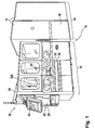
- FIG 1 shows a perspective view of a laboratory equipment unit 10 comprising a laboratory system of the invention.
- This laboratory equipment unit 10 may be a so-called storage retrieval module (SRM) forming part of an overall laboratory analyser system.
- the storage retrieval module comprises a rack handler section 12 (on the left hand side of the depiction of Figure 1 ) and a refrigerating or storage section 14 (on the right hand side of the depiction of Figure 1 ). Between the two sections 12, 14 there is a loading/unloading interface (not shown) through which racks are transferred from the rack handler section 12 into the storage section 14 and back (in case of retrieval).
- This loading/unloading interface may be designed like a gate or the like.
- the storage section 14 may comprise a refrigerator 16.
- a storage section in the context of this invention is a cabinet of various size which is able to store a plurality of sample tubes, preferably in storage racks. It may have an appropriate tempering unit to hold the ambient temperature for the tubes within the refrigerator below room temperature, possibly below 18 °C and possibly below 10 °C.
- the storage section 14 comprises a plurality of shelves for storage of a high number of sample tube racks.
- the sample tube racks loaded into the storage section are so-called storage racks. This implies that all tubes contained in primary racks (i.e. incoming racks of various types) fulfilling the geometry criteria of the invention are taken out of their respective primary racks and are resorted in suitable storage racks before being loaded into the storage section 14.
- the storage section may be large enough for one or two human beings being able to enter the inside of the storage section 14 through a door (not shown). In case the door is opened, a safety switching circuit ensures that all moving systems (like robotic arms or other transfer or conveying systems) come to a standstill, for example in a neutral or home position.
- the secondary racks and particularly the storage racks are multi-row racks (e.g. three rows with more than ten positions, for example 13 to 14 positions). Therefore, the secondary racks are more stable, particularly for storing purposes, and less likely to tilt over.
- the storage section 14 comprises a disposal unit 18.
- the disposal unit 18 is connected with the storage section 14 via an internal opening (not shown) in a wall separating the storage section 14 from the disposal unit 18. Through this opening, sample tubes whose expiration date (i.e. shelf life) has elapsed can be disposed automatically through the disposal unit 18.
- the rack handler section 12 has a housing consisting of several outer walls with windows so that operating personal can have a direct visual overview of the rack handler's functioning.
- the rack handler section 12 comprises an opening 20 in one of the outer walls through which primary racks can be inserted into the storage retrieval module 10.
- the opening 20 leads to a primary rack handler area 210 (cf. Figure 2 ) which comprises at least one robotic arm 220 (which can be seen in the depiction of Figure 1 through one of the windows).
- the opening 20 might be closable by means of a sliding or retractable door (not shown).
- the rack handler section 12 further comprises drawers 22, 24 through which emptied primary racks and/or primary racks containing sample tubes with error designations and/or racks containing at least one retrieved sample tube can be taken out of the storage retrieval module 10.
- the rack handler section 12 comprises a capping station 26 with a feeder tank 28 for tube caps.
- the storage retrieval module 10 also comprises a man-machine interface (MMI) 30 which might have the form of a touch screen monitor 32 at the end of an articulated arm 34.
- MMI man-machine interface
- FIG 2 shows a top view of the primary rack handler area 210 of the laboratory system of the invention.
- the primary rack handler area 210 comprises a platform 212 inside the rack handler section 12 of Figure 1 . It further comprises a first robotic arm 220 which may be installed essentially in the centre of the platform 212 or at least at a position from which it can reach at least all locations within the primary rack handler area 210. Any known suitable robot can be used for this purpose, such as for example a SCARA robot with four axes and four degrees of freedom.
- the robotic arm 220 comprises, at its end, a gripper 222 designed to securely grip the racks to be handled.
- a conveyor 214 is provided for conveying incoming primary racks PR containing sample tubes (e.g. five sample tubes) to an image analysing unit 250 which is also positioned on the platform 212.
- sample tubes e.g. five sample tubes
- a plurality of alignment elements 230 are provided on the platform 212.
- the alignment elements 230 are designed to hold in place the primary racks PR in a desired alignment or orientation which corresponds to an orientation of the gripper 222 of the robotic arm 220.
- the primary racks may not be introduced directly on the conveyor 214 through the opening 20 but rather be taken up by the gripper 222 of robotic arm 220 and then placed on the conveyor 214.
- a receiving position (not shown) for incoming racks is provided from which the robotic arm then takes up the incoming rack in order to place it onto the conveyor 214.
- the conveyor 214 conveys the primary rack into the image analysing unit 250 where the sample tubes in the primary rack are analysed as to their geometry parameters.
- the determined geometry parameters of each sample tube are compared with predetermined geometry criteria and it is identified whether a sample tube is system conform or not.
- One of the geometry parameters to be analysed is the presence of a cap on the sample tube, other parameters to be analysed are for example the tube's diameter and height.
- the whole primary rack is sent to the capping station 26 before any other further processing.
- the first robotic arm 220 places the primary rack onto the conveyor 240 conveying the primary rack with its sample tubes into the capping station 26 for a re-capping of the sample tube(s) identified to have no cap.
- the primary rack is brought back into the regular processing as explained in more detail below.
- the primary rack can be transferred back into the image analysing unit 250 in order to make sure that now all sample tubes carry a cap and are fit for further processing.
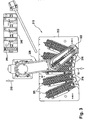
- Figure 3 shows a top view of a resorting station 310 according to the invention.
- the resorting station 310 is also a part of the rack handler section 12 and is positioned adjacent to the primary rack handler area 210 of Figure 2 .
- the resorting station 310 may be positioned on the left hand side of the primary rack handler area 210 in the depiction of Figure 2 , as indicated by reference numeral 310 in Figure 2 .
- the resorting station 310 comprises a storage rack docking element 312 which is designed to receive a plurality of storage racks SR.
- the storage rack docking element 312 has basically the form of a substantially rectangular plate with a number of recesses 314 (five recesses in the embodiment shown in the drawings) adapted to fittingly receive according storage racks SR (cf. also Figure 4 ).
- the resorting station 310 further comprises a second robotic arm 320 which is positioned behind the storage rack docking element 312 in such a manner that a gripper 322 attached to the second robotic arm 320 may be able to reach any location within the resorting station 310.
- the second robotic arm 320 is of similar or identical type as the first robotic arm 220 of the primary rack handler area 210 as described above but is provided with a different gripper 322, namely a sample tube gripper whereas the first robotic arm 220 of the primary rack handler area 210 is provided with a primary rack gripper 222.
- the resorting station 310 comprises a primary rack docking element 340 which is located at a position very close to the primary rack handler area 210 so as to be easily reachable by the first robotic arm 220 of the primary rack handler area 210 in order to be loaded with primary racks.
- arrows with reference numerals 14 and 210 respectively, indicate the orientation of the resorting station 310, i.e. the primary rack docking element 340 and the back side of the second robotic arm 320 of the resorting station 310 are oriented towards the primary rack handler area 210 whereas the storage rack docking element 312 and the front side of the second robotic arm 320 are oriented towards the refrigerating or storage section 14.
- a primary rack PR containing sample tubes S is conveyed into the image analysing unit 250 by means of conveyor 214 where the sample tubes S are analysed as to given predetermined geometric parameters in order to determine whether a sample tube is system conform or non-system conform.
- the primary rack PR is transferred, by means of the first robotic arm 220 of the primary rack handler area 210, to the primary rack docking element 340 (assuming that all sample tubes in the primary rack where found to carry a cap; otherwise there would first follow the re-capping procedure as described above, followed by another image analysis as the case may be).
- the second robotic arm 320 of the resorting station 310 starts unloading the sample tubes S contained in primary rack PR by taking them up subsequently with its tube gripper 322.
- the tube gripper 322 takes up a single sample tube S and moves it towards the storage rack docking element 312.
- the sample tube S passes a barcode reader (not shown) which is positioned in front of the second robotic arm 320 in such a manner that the second robotic arm 320 may move the sample tube S, on its way to the storage racks SR, along the optical path of the barcode reader, at the same time rotating the sample tube slowly so that the barcode applied to the outer surface of the sample tube can be read by the barcode reader.
- a barcode reader (not shown) which is positioned in front of the second robotic arm 320 in such a manner that the second robotic arm 320 may move the sample tube S, on its way to the storage racks SR, along the optical path of the barcode reader, at the same time rotating the sample tube slowly so that the barcode applied to the outer surface of the sample tube can be read by the barcode reader.
- the second robotic arm 320 "knows" which sample tube in the primary rack about to be unloaded is system conform and thus is to be unloaded. Therefore, only sample tubes which where categorized before as system conform will be unloaded in the resorting section 310 while the sample tubes which where categorized as non-system conform will remain in the primary rack.
- the system double checks if the sample tube held by the tube gripper 322 is system conform and retrieves the data necessary for resorting, e.g. the sample tube's diameter and/or the sample tube's shelf life. These may be the two main parameters for resorting. Accordingly, a plurality of storage racks SR is provided on the storage rack docking element 312 with various diameter openings for receiving sample tubes from the second robotic arm 320. This means, that all sample tubes with a given diameter are correspondingly put in an appropriate storage rack, and that only sample tubes with the same shelf life are put into the same storage rack. Other sorting criteria are, of course, possible, such as e.g. tube height.
- each storage rack SR is not positioned in parallel to each other, but along a circle segment and pointing towards the gate (not shown) leading to the refrigerating or storage section 14 (i.e. the loading/unloading interface between the two sections 12, 14).
- the gate opens and a (third) robotic transfer system (cf. Figure 5 and 6 ) which is positioned within the refrigerator 16 extends trough the gate opening and takes up the according storage rack in order to transfer it into the refrigerator.
- a front surface 90 of each storage rack SR comprises a vertical slot 92, at the lower end of which a substantially horizontal circular opening 94 is provided (cf.
- the third robotic transfer system may couple with the storage rack by engaging into the circular opening 94 with an appropriate complementary element, e.g. a hook 526 with appropriate dimensions, and draw the storage rack onto a platform of the third robotic transfer system.
- an appropriate complementary element e.g. a hook 526 with appropriate dimensions
- the storage rack docking element 312 is provided with a plurality of recesses for receiving the storage racks, the recesses having a tee slot cross-section in which the storage rack SR can slidingly engage with corresponding extensions 96 provided along the lower edges of its lateral faces 98. Further, the storage rack docking element 312 is provided with orientation and abutment elements 316 in front of each recess 314 to facilitate positioning of the robotic transfer system in front of the storage racks.
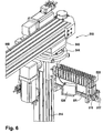
- a robotic transfer system 510 of the invention comprises a carrier element 512 with substantially vertical extension which can move along a vertical post 514 in longitudinal guide slots 516 by means of appropriate electric motors.
- the carrier element 512 carries a platform 518 which can protract forward from carrier element 512 by means of an electric motor 520 and belt drive 522.
- the carrier element 512 further comprises a kit 524 which is slidingly positioned on the platform 518 and which, at its front, is provided with the hook-like element 526 for engagement with the corresponding horizontal opening 94 of a storage rack SR.
- the robotic transfer system 510 further comprises a barcode reader 530 which is positioned in such a manner that it can read the barcode label applied to the barcode surface 91 of a storage rack SR when the carrier element 512 and platform 518 are positioned in front of the storage rack.
- the barcode reader 530 may be attached to the carrier element with a slight angle as shown in Figure 6 .
- the robotic transfer system 510 comprises a rail bar 540 on the underside of which the vertical post 514 is slidingly attached by means of a sled 542, the sled 542 being able to move along guide slots of rail bar 540.
- the rail bar 540 may be attached to a ceiling of the refrigerator 16 so that an overhead movement of the robotic transfer system 510 is possible, with the advantage that the floor of the refrigerator along the aisle between the shelves remains free from any guide bars or rails.
- the refrigerator may be provided with suitable sensors so that when a person enters the refrigerator the robotic transfer system comes to a standstill or first moves to a neutral or home position, e.g. at the opposite aisle end from the door, where it then comes to a standstill.
- the sensors might be connected to the door (such as a safety switching circuit) and/or to the floor area (such as a light barrier, any other photosensitive relay, a step sensor which senses weight on the floor etc.).
- the vertical post 514 of the robotic transfer system 510 is attached to the sled 542 by means of a rotary joint 544 which enables full rotary movement of the post 514 together with the carrier element 512.
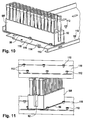
- FIGs 10 and 11 show perspective views of a storage rack SR in storage position on a shelf 110.
- Each shelf 110 comprises a plurality of T-pins 112 which are aligned on the shelves 110 so as to form a receiving compartment for a storage rack SR.
- the distance between two pins 212 in longitudinal direction of a shelf 110 may be about equal to the width of the storage rack SR at its bottom side including the longitudinal extensions 96.
- a pin 112 may be provided at about half length of a storage rack and/or at the rear side of the shelf (cf. Figures 10 and 11 , respectively).
- the T-shape of the pins 112 ensures a fitting position of the storage rack SR on the shelf as the longitudinal extensions 96 are positioned below the heads of the T-shaped pins, encompassing so-to-say underneath the heads of the T-shaped pins, and thus the racks can only be moved in one direction.
- the shelves 110 may comprise elevated retaining elements 114 indicated in Figure 10 .
- the retaining elements 114 are preferably located in the back area of each shelf 110 and are designed to fit underneath a corresponding recess 116 of the storage rack SR.
- the elevated retaining element 114 may be formed by a stamping of the sheet metal of the shelf or any other appropriate method. Although it may be possible to form the retaining element on the shelf by fixing it thereto (such as glueing, screwing, welding), it should be advantageous to make it in one piece with the shelf for robustness reasons.
- the recess 116 at the bottom side of the storage rack SR may have a concave form to better fit with the elevated retaining element 114.
- the retaining element 114 has the function to retain the fully inserted storage rack in its storage position, thus preventing the storage rack e.g. to slowly move away from the storage position and possibly fall, due to e.g. vibrations during operation of the system.
- Such elevated retaining elements 114 may, of course, also be provided in the recesses 314 of the storage rack docking element 312.
- the platform 518 is connected with a height adjustment device, preferably together with the carrier element 512.
- the height adjustment device lowers the platform slightly with regard to the level of the shelf from which a storage rack is to be pulled just before the storage rack is pulled onto the platform in order to avoid that the storage rack might get stuck at the front edge of the platform 518 when being pulled from the shelf onto the platform.
- the height adjustment device raises the platform slightly with regard to the level of the shelf for the same reason, i.e. in order to avoid that the platform might get stuck with its front edge when being pushed over the front edge of the shelf.
- the program of the CPU controlling the robotic transfer system 510 runs a self-teaching routine.
- This self-teaching routine works by means of a sensor reading markings along the shelves, e.g. applied to each of the respective top shelf storage rack end positions and bottom shelf storage rack end positions and with the information of how many storage positions per shelf and how many shelves (i.e. rows of shelves) one shelf wall of the storage section comprises.
- the self-teaching routine allows the robotic transfer system 510 to gauge itself by having the robotic transfer system 510 move to a first storage rack end position of either the top or the bottom shelves, then move horizontally along the shelf until it identifies the respective opposing storage rack end position, all by measuring the distance between the two storage rack end positions.
- the robotic transfer system 510 moves vertically to the respective opposing bottom or top shelf until it identifies the third storage rack end position, again by measuring the distance between the two storage rack end positions. Then, the robotic transfer system 510 moves again horizontally along the shelf to the fourth storage rack end position, again measuring the distance between these two storage rack end positions. To make it complete, the robotic transfer system 510 may optionally move again vertically to the initial storage rack end position to obtain a fourth measured distance. Of course, the order of the movement is not binding, the robotic transfer system 510 may also first move vertically before moving horizontally.
- the described self-teaching routine can be done on the basis of e.g. four markings, i.e. one marking per storage rack end position.
- Gauging is then obtained by calculating the distances between individual storage positions by dividing the distance between horizontal storage rack end positions by the number of storage rack positions and by dividing the distance between vertical storage rack end positions by the number of shelves and by storing the absolute coordinates of the four storage rack end positions.
- the robotic transfer system 510 may find every shelf storage position with its internal coordinate system.
- a similar self-teaching routine is executed also with respect to the storage rack docking element 312 shown in figure 4 , when a storage rack SR has to be stored or retrieved, wherein the abutment elements 316 have the function of markings located in front of each recess 314.
- Figure 12 shows a schematic perspective view of the disposal unit 18 which is a part of the storage section 14, being located outside of the refrigerator 16 but adjacent to the refrigerator 16.
- the refrigerator 16 and the disposal unit 18 are separated by a partition wall 610 (only a portion of which is shown in Figure 12 ) which is provided with a gate opening 612 large enough for a fully loaded storage rack to pass through.
- the disposal unit 18 comprises a tilt module 620 which may be fixedly attached to the partition wall 610 in alignment with the gate opening 612. Attachment may be done for example by means of bolts and nuts with appropriate dimensions (cf. Figure 12 ). Underneath the tilt module 620, there is provided a waste container 640.
- the tilt module comprises a storage rack park position 622.
- the rack park position 622 may be a platform with guide elements with a T- or L-shaped cross-section for holding the storage rack SR in position when the storage rack SR is tilted over in the tilt module 620.
- the guide elements may be guide grooves formed by raised side edges, encompassing the lower edges of a storage rack when being slid in the park position so that the protruding extensions 96 provided along longitudinal edges of the storage rack engage with the raised edges guide grooves of the platform 622.
- the platform 622 may comprise, as guide elements, T-shaped guide pins 112 as described above in connection with the shelves 110 of the storage section 14.
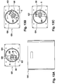
- the rack park position 622 is provided within a drum 624 which is rotatable around a centre axis 626.
- a storage rack SR is pushed into the drum 624 in the rack park position 622 by means of the robotic transfer system 510 of the refrigerator 16 through the gate opening 612 in the partition wall 610 between refrigerator 16 and disposal unit 18.
- the drum 624 rotates about the rotation axis 626, e.g. counter-clockwise as shown in Figures 13A, 13B and 13C so that the storage rack module held in place in the rack park position 622 by the above-described guide grooves is tilted over and the sample tubes S contained therein fall, due to gravity, in the waste container 640 provided below the tilt module 620.
- the robotic transfer system 510 of the refrigerator 16 may be adapted (not shown) to extend through the gate opening 612 in the partition wall 610 between refrigerator 16 and disposal unit 18 and to rotate about a rotation axis so that the storage rack module is held in place and the sample tubes S contained therein fall, due to gravity, in the waste container 640 provided underneath.
- the method of the invention comprises the steps of loading storage racks (SR) into the storage section (14) through a gate by means of the robotic transfer system (510), of retrieving, upon need or after a certain time period, e.g. shelf life, has elapsed, a storage rack (SR) from the storing section (14) through a gate by means of the robotic transfer system (510), in case the certain time period has lapsed, bringing a storage rack (SR) into the disposal unit (18) by means of the robotic transfer system (510), and disposing sample tubes through the disposal unit (18).
- a certain time period e.g. shelf life
- the rack park position 622 is located off-centre from the rotation axis 626 which makes that the storage rack SR itself is not rotated but rather tilted so that the process of turning over the storage rack SR is smoothened so that the sample tubes rather slide out of the storage rack than fall out of the same.
- This effect is intensified by the presence of two side walls 628 within the drums 624 which extend adjacent to the side walls 98 of the storage rack SR beyond the height of the tubes S.
- the sample tubes S fall or rather slide out of the drums 624 in a controlled manner so that the likelihood of a sample tube dropping outside of the waste container 640 is ruled out or at least minimised.
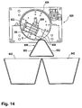
- FIG 14 shows an alternative embodiment of the disposal unit.
- This embodiment comprises two smaller waste containers 642.
- the tilt module 620 remains unchanged compared to the embodiment shown in Figure 13 (merely the rack park position 622 is located on the other side of the rotation axes 626 in a mirror-inverted manner).
- the deflector 650 has a cross-section of substantially triangular form (which makes it some kind of double deflector with two downwardly sloped deflector plates 652) and is positioned with its midperpendicular plane vertically above the adjacent edges of the two waste containers 642 touching each other.
- the positioning of the triangular deflector 650 is such that, when the drum 624 is rotated in either direction, the sample tubes S falling or sliding out of the storage rack SR first slide along the side walls 628 and then along either one of the two sloped plates 652 of the deflector 650 into the respective waste container 642 as the triangular cross-section is sloped towards the upper openings of the waste containers.
- the double deflector 650 therefore prevents sample tubes S from falling in between the two waste containers 642 or from hitting the edges of the waste containers 642 placed below the drum 624 which could make them rebound and fall next to the waste containers.
- a sensor may be provided in order to detect when the waste container is full and should be changed. This sensor might be connected to a control unit or CPU (not shown) of the tilt module in order to disrupt operation of the tilt module until the waste container is emptied or replaced in order to prevent sample tubes overflowing and samples being spilled. Another sensor may be also provided to check that the functioning of the drum 624, e.g. angle of rotation, receiving position, etc. are correct.
- the emptied storage rack is withdrawn from the disposal unit 18 by the robotic transfer system 510.
- a sensor 528 located on the robotic transfer system 510 may detect whether any tube has remained in the storage rack SR. If this is the case, a non-conform status is detected and the storage rack SR is e.g. transported to a park position, e.g. on one of the upper shelves 110 of the storage section 14 where more space in height is allocated, before further processing.
- the same or another sensor may have also the function of height sensor, e.g. to check during the operation of storing a storage rack that the height of the tubes does not exceed a certain threshold value, e.g. given by the distance between two shelves of the refrigerator 16.
- the storage rack is transported to a storage rack docking element 312 of the resorting section 310.
- the sample tubes S remained in the storage rack are resorted to a different rack, e.g. a waste rack WR, which preferably comprises larger diameter openings, typically larger than the diameter of any tube handled by the system, e.g. 2-3 cm diameter or more.
- the waste rack WR is transported by the robotic transfer system 510 to the disposal unit 18 and the disposal procedure is repeated. The overall process may be repeated more times if necessary. Normally, the use of larger diameter openings in the waste rack WR reduces the risk that this occurs.
- the method of the invention may comprise the steps of sensing by means of a sensor 528 whether sample tubes S have remained in the storage rack SR after disposing and in the affirmative transporting the storage rack SR to a park position and/or resorting the remained sample tubes S to a waste rack WR and repeating the disposal procedure.
Description
- The present invention relates to the handling of sample tube racks in a test laboratory environment, and particularly to a laboratory device for handling sample tube racks in the context of storing such sample tubes in a storage compartment. More particularly, the present invention relates to an automated tubes identification system.
- In laboratories, such as for example clinical laboratories in which patient samples are examined and submitted to various in-vitro diagnosis tests, test tubes containing samples (such as blood, urine, etc.) have to be handled in high number and in a cautious but still efficient manner. For years now, automated procedures with corresponding systems and devices have been used in this context.
- One aspect during the handling of these sample tubes relates to the tubes being placed in a storage compartment which can be, for example, a refrigerating device. For efficient handling purposes, the tubes are not handled individually but placed in so-called racks. Usually, the tubes are placed in special storage racks, which storage racks are then placed into storage compartments such as shelves in the storage device for a predefined time. During this time frame, racks may have to be retrieved by the rack handling device e.g. in order to deliver a sample tube (which is contained on that rack) in response to a request for further analysis, and subsequently be placed back into storage.
- Document
EP 1 441 026 discloses a storage system which has a cabinet with controlled climatic conditions, and ring-shaped holders to store the samples within its interior. An automatic transport system moves the samples, with a mechanism to load and unload them within the sample holders. The loading/unloading mechanism and/or the sample holders rotate around a centre axis. The samples are inserted and removed over the top of the assembly by a telescopic mechanism, with a vertical lift column and a transfer guide with a relative vertical movement at the lift trolley through a lock at the upper cover. -
United States Patent 6,129,428 discloses an object storage device which is a carousel and holds objects in object carriers. They lie only partially on a structure of the object storage device and can be lifted up. The storage station has a carousel-like object storage device and a transport device with an element for holding the object carriers which moves the object carriers parallel and perpendicular to the axis of the carousel-like object storage device. The climatic test cabinet has a window and a storage station inside it consisting of an object storage device and a transport device, which transports one of the object carriers at a time back and forth between the object storage device and the vicinity of the window. -
United States Patent 6,478,524 discloses a storage arrangement and a storage receptacle for objects, wherein the storage arrangement has a storage device with at least one storage shaft containing several storage spaces arranged on top of each other, and a delivery device for the short-term reception of the objects. The storage arrangement furthermore has a transport device with an object carrier, and has a vertical displacement device, a horizontal rotating device and a horizontal displacement device for displacing the object carrier between the delivery device and the storage spaces. The objects always take up the same angle in respect to the vertical line, wherein a base surface of the objects is preferably horizontally oriented. The storage receptacle consists of a storage cabinet and an integrated storage arrangement. The storage cabinet has a lock window opening, whose dimensions correspond to the dimensions of an object. The delivery device is located outside the storage cabinet. -
US 2007/0172396 A1 discloses an automated storage system for storing large quantities of samples and trays. The storage system includes a storage compartment, a separate tray shuttle compartment which is abutting the storage compartment on one side and a plurality of independent modules on the other side. Incoming trays are handled through the independent modules into the tray shuttle compartment which again is distributing the trays to a robotic shelf system which stores the trays in designated locations in the storage compartment. For retrieving, the tray shuttle selects a designated tray, delivering it to the plurality of independent modules for performing processing of samples there. In other words, this document discloses a laboratory system to handle laboratory sample tube racks, comprising a storage section with a plurality of shelves for storing a plurality of storage, the storage section further comprising a disposal unit for disposing sample tubes from the storage racks, and a robotic transfer system, the robotic transfer system being designed to load storage racks into the storage section, to retrieve storage racks from the storing section. -
WO 95/05590 A1 -
WO 2009/077465 A1 discloses an apparatus for automatically depositing, preserving and retrieving test tubes, comprising a refrigerated storage with movable horizontal shelves and a conveyor interface, adapted to automatically transport biological material test tubes, and a device adapted to handle the test tubes between the interface and the containers of a sorted plurality of test tubes. The containers can be placed on the lanes of a bench. A handling device is provided between the bench and an access area of the storage, slidingly mounted to the bench for horizontally moving the containers between the access area of the storage and the bench. A control unit is adapted to coordinate the devices during the loading/ unloading operations by means of locating means adapted to locate each test tube in the storage, thus allowing the automatic retrieval of said test tube from the storage from any point therein and at any time. -
US 2002/064881 A1 discloses a method to additionally test a patient's specimen using an analyzer some period of time after initial tests on an aliquot of the patient's specimen are completed by retaining the aliquot of the patient's specimen within the analyzer or by retaining another aliquot of the patient's specimen within the analyzer for a period of time. -
EP 1737031 A discloses an automatic teaching method for a transfer mechanism in the field of wafer technology. -
JP2007161453 A - The present invention provides a laboratory system to handle sample tube racks with the features of claim 1, as well as a method with the features of
claims 11 and 12, respectively. - According to the invention, a laboratory system for handling laboratory sample tube racks comprises a storage section with a plurality of shelves for storing a plurality of storage racks, a disposal unit for disposing sample tubes from the storage racks, and a robotic transfer system for loading storage racks into the storage section, for retrieving storage racks from the storing section and for bringing storage racks to the disposal unit after a given storage time has elapsed. According to a preferred embodiment, the conveying system comprises a coupling element for coupling with the storage rack to be conveyed, the coupling element transferring push/pull forces on the storage rack when coupled thereto. The conveying system further comprises a platform for carrying the storage rack to be conveyed, the platform being operatively connected with a height adjustment device. In case a storage rack is pulled onto the platform from a storing position e.g. on a shelf in the storage device, the height adjustment device lowers the platform slightly below the level of the storage position from which the rack is pulled. In case a storage rack is pushed from the platform in a storing position e.g. onto a shelf in the storage device, the height adjustment device raises the platform slightly above the level of the storage position into which the storage rack is pushed.
- Thus, according to the invention, the level of the storage handler platform is adjusted depending on the direction in which the storage rack is handled, thus allowing for proper insertion and retraction/retrieval of the storage racks.
- The invention further provides a laboratory system to handle laboratory sample tube racks after expiration of a predefined time limit of storing. According to a preferred embodiment, the disposal unit comprises a tilt module with a rack park position positioned above a waste container. The tilt module is designed to tilt over the rack park position when loaded with a rack by the conveying system such that sample tubes contained in the rack fall into the waste container below.
- According to the invention, a rack containing sample tubes to be disposed is placed into the tilt module. Following tilting over of the rack park position, the sample tubes fall out of the rack due to gravity and into the waste container below. This allows for automated disposal of tubes, ensuring that no tubes fall next to the waste container. A deflector or baffle plate may be positioned between the tilt module and the waste container for guiding falling sample into the waste container. After the rack has been emptied, it is brought back into a regular (non-tilted) position and retrieved by the conveying system. During retraction, a sensor may detect whether any tube has remained in the rack. The delivering/retrieving mechanism carried out by the conveying system with respect to the tilting module can be the same or similar to that carried out with respect to a storing position.
- Further features and embodiments will become apparent from the description and the accompanying drawings.
- It will be understood that the features mentioned above and those described hereinafter can be used not only in the combination specified but also in other combinations or on their own, without departing from the scope of the present disclosure. The disclosure of the invention also covers the corresponding methods of operation of the disclosed devices and systems, and the present description also covers a computer program with program coding means which are suitable for carrying out the methods of the invention when the computer program is run on a computer or control unit. The computer program itself as well as stored on a computer-readable medium is claimed.
- Various implementations are schematically illustrated in the drawings by means of an embodiment by way of example and are hereinafter explained in detail with reference to the drawings. It is understood that the description is in no way limiting on the scope of the present disclosure and is merely an illustration of a preferred embodiment.
-
-
Figure 1 shows a perspective view of a laboratory equipment unit comprising a laboratory system of the invention. -
Figure 2 shows a top view on a primary rack handler area of the laboratory system of the invention where incoming primary racks are handled. -
Figure 3 shows a top view of a resorting station according to the invention. -
Figure 4 shows a top perspective view of a storage rack docking element of the resorting station ofFigure 3 . -
Figure 5 shows a first perspective view of a robotic transfer system for handling storage racks. -
Figure 6 shows a second perspective view of the robotic transfer system for handling storage racks ofFigure 5 . -
Figure 7 shows an enlarged detail of a hook of the robotic transfer system for handling storage racks ofFigure 5 engaging with a storage rack. -
Figure 8 shows a perspective view of a storage rack. -
Figure 9 shows an enlarged detail of the storage rack ofFigure 8 . -
Figure 10 is a perspective view of a storage rack on a storage shelf of the invention. -
Figure 11 is another perspective view of a storage rack between two shelves. -
Figure 12 is a perspective top view of a disposal unit of the invention and the robotic transfer system ofFigure 5 . -
Figures 13A to 13C show front views of a drum of the disposal unit ofFigure 12 in subsequent operation steps. -
Figure 14 shows another embodiment of the disposal unit of the invention. - Reference will now be made in detail to some embodiments, examples of which are illustrated in the accompanying drawings. Wherever possible, the same reference numbers are used throughout the drawings to refer to the same or like parts.
-
Figure 1 shows a perspective view of alaboratory equipment unit 10 comprising a laboratory system of the invention. Thislaboratory equipment unit 10 may be a so-called storage retrieval module (SRM) forming part of an overall laboratory analyser system. The storage retrieval module comprises a rack handler section 12 (on the left hand side of the depiction ofFigure 1 ) and a refrigerating or storage section 14 (on the right hand side of the depiction ofFigure 1 ). Between the twosections rack handler section 12 into thestorage section 14 and back (in case of retrieval). This loading/unloading interface may be designed like a gate or the like. - The
storage section 14 may comprise arefrigerator 16. A storage section in the context of this invention is a cabinet of various size which is able to store a plurality of sample tubes, preferably in storage racks. It may have an appropriate tempering unit to hold the ambient temperature for the tubes within the refrigerator below room temperature, possibly below 18 °C and possibly below 10 °C. - In its inside, the
storage section 14 comprises a plurality of shelves for storage of a high number of sample tube racks. According to the invention, the sample tube racks loaded into the storage section are so-called storage racks. This implies that all tubes contained in primary racks (i.e. incoming racks of various types) fulfilling the geometry criteria of the invention are taken out of their respective primary racks and are resorted in suitable storage racks before being loaded into thestorage section 14. The storage section may be large enough for one or two human beings being able to enter the inside of thestorage section 14 through a door (not shown). In case the door is opened, a safety switching circuit ensures that all moving systems (like robotic arms or other transfer or conveying systems) come to a standstill, for example in a neutral or home position. While primary racks are single-row racks with somewhat standard geometry and therefore designed to be handled in a plurality of different laboratory systems, the secondary racks and particularly the storage racks are multi-row racks (e.g. three rows with more than ten positions, for example 13 to 14 positions). Therefore, the secondary racks are more stable, particularly for storing purposes, and less likely to tilt over. - Further, the
storage section 14 comprises adisposal unit 18. Thedisposal unit 18 is connected with thestorage section 14 via an internal opening (not shown) in a wall separating thestorage section 14 from thedisposal unit 18. Through this opening, sample tubes whose expiration date (i.e. shelf life) has elapsed can be disposed automatically through thedisposal unit 18. - The
rack handler section 12 has a housing consisting of several outer walls with windows so that operating personal can have a direct visual overview of the rack handler's functioning. Therack handler section 12 comprises anopening 20 in one of the outer walls through which primary racks can be inserted into thestorage retrieval module 10. Theopening 20 leads to a primary rack handler area 210 (cf.Figure 2 ) which comprises at least one robotic arm 220 (which can be seen in the depiction ofFigure 1 through one of the windows). Theopening 20 might be closable by means of a sliding or retractable door (not shown). - The
rack handler section 12 further comprisesdrawers storage retrieval module 10. - Further, the
rack handler section 12 comprises acapping station 26 with afeeder tank 28 for tube caps. - The
storage retrieval module 10 also comprises a man-machine interface (MMI) 30 which might have the form of a touch screen monitor 32 at the end of an articulatedarm 34. -
Figure 2 shows a top view of the primaryrack handler area 210 of the laboratory system of the invention. The primaryrack handler area 210 comprises aplatform 212 inside therack handler section 12 ofFigure 1 . It further comprises a firstrobotic arm 220 which may be installed essentially in the centre of theplatform 212 or at least at a position from which it can reach at least all locations within the primaryrack handler area 210. Any known suitable robot can be used for this purpose, such as for example a SCARA robot with four axes and four degrees of freedom. Therobotic arm 220 comprises, at its end, agripper 222 designed to securely grip the racks to be handled. - On the
platform 212, aconveyor 214 is provided for conveying incoming primary racks PR containing sample tubes (e.g. five sample tubes) to animage analysing unit 250 which is also positioned on theplatform 212. - Further, a plurality of
alignment elements 230 are provided on theplatform 212. Thealignment elements 230 are designed to hold in place the primary racks PR in a desired alignment or orientation which corresponds to an orientation of thegripper 222 of therobotic arm 220. In order to ensure proper orientation of the primary racks PR in every step of processing (such that the sample tubes positions are always unambiguously identifiable), the primary racks may not be introduced directly on theconveyor 214 through theopening 20 but rather be taken up by thegripper 222 ofrobotic arm 220 and then placed on theconveyor 214. For this, a receiving position (not shown) for incoming racks is provided from which the robotic arm then takes up the incoming rack in order to place it onto theconveyor 214. - The
conveyor 214 conveys the primary rack into theimage analysing unit 250 where the sample tubes in the primary rack are analysed as to their geometry parameters. The determined geometry parameters of each sample tube are compared with predetermined geometry criteria and it is identified whether a sample tube is system conform or not. One of the geometry parameters to be analysed is the presence of a cap on the sample tube, other parameters to be analysed are for example the tube's diameter and height. - In case a sample tube is found to have no cap, the whole primary rack is sent to the
capping station 26 before any other further processing. For this, the firstrobotic arm 220 places the primary rack onto theconveyor 240 conveying the primary rack with its sample tubes into thecapping station 26 for a re-capping of the sample tube(s) identified to have no cap. After successful re-capping of the sample tube(s), the primary rack is brought back into the regular processing as explained in more detail below. Alternatively, as the case may be, the primary rack can be transferred back into theimage analysing unit 250 in order to make sure that now all sample tubes carry a cap and are fit for further processing. -
Figure 3 shows a top view of a resortingstation 310 according to the invention. The resortingstation 310 is also a part of therack handler section 12 and is positioned adjacent to the primaryrack handler area 210 ofFigure 2 . For example, the resortingstation 310 may be positioned on the left hand side of the primaryrack handler area 210 in the depiction ofFigure 2 , as indicated byreference numeral 310 inFigure 2 . - The resorting
station 310 comprises a storagerack docking element 312 which is designed to receive a plurality of storage racks SR. The storagerack docking element 312 has basically the form of a substantially rectangular plate with a number of recesses 314 (five recesses in the embodiment shown in the drawings) adapted to fittingly receive according storage racks SR (cf. alsoFigure 4 ). - The resorting
station 310 further comprises a secondrobotic arm 320 which is positioned behind the storagerack docking element 312 in such a manner that agripper 322 attached to the secondrobotic arm 320 may be able to reach any location within the resortingstation 310. The secondrobotic arm 320 is of similar or identical type as the firstrobotic arm 220 of the primaryrack handler area 210 as described above but is provided with adifferent gripper 322, namely a sample tube gripper whereas the firstrobotic arm 220 of the primaryrack handler area 210 is provided with aprimary rack gripper 222. - Further, the resorting
station 310 comprises a primaryrack docking element 340 which is located at a position very close to the primaryrack handler area 210 so as to be easily reachable by the firstrobotic arm 220 of the primaryrack handler area 210 in order to be loaded with primary racks. In the illustration ofFigure 3 , arrows withreference numerals station 310, i.e. the primaryrack docking element 340 and the back side of the secondrobotic arm 320 of the resortingstation 310 are oriented towards the primaryrack handler area 210 whereas the storagerack docking element 312 and the front side of the secondrobotic arm 320 are oriented towards the refrigerating orstorage section 14. - In operation, a primary rack PR containing sample tubes S is conveyed into the
image analysing unit 250 by means ofconveyor 214 where the sample tubes S are analysed as to given predetermined geometric parameters in order to determine whether a sample tube is system conform or non-system conform. After this analysis, the primary rack PR is transferred, by means of the firstrobotic arm 220 of the primaryrack handler area 210, to the primary rack docking element 340 (assuming that all sample tubes in the primary rack where found to carry a cap; otherwise there would first follow the re-capping procedure as described above, followed by another image analysis as the case may be). - When a primary rack PR is positioned in the primary
rack docking element 340 of the resorting station, the secondrobotic arm 320 of the resortingstation 310 starts unloading the sample tubes S contained in primary rack PR by taking them up subsequently with itstube gripper 322. Thetube gripper 322 takes up a single sample tube S and moves it towards the storagerack docking element 312. On its way there, the sample tube S passes a barcode reader (not shown) which is positioned in front of the secondrobotic arm 320 in such a manner that the secondrobotic arm 320 may move the sample tube S, on its way to the storage racks SR, along the optical path of the barcode reader, at the same time rotating the sample tube slowly so that the barcode applied to the outer surface of the sample tube can be read by the barcode reader. - As all electronic elements of the
laboratory equipment unit 10, namely the robotic arms and their respective control units, the image analysing unit, the barcode readers etc., are connected to a central CPU with a database, the secondrobotic arm 320 "knows" which sample tube in the primary rack about to be unloaded is system conform and thus is to be unloaded. Therefore, only sample tubes which where categorized before as system conform will be unloaded in the resortingsection 310 while the sample tubes which where categorized as non-system conform will remain in the primary rack. - By means of the barcode reader of the resorting
section 310, the system double checks if the sample tube held by thetube gripper 322 is system conform and retrieves the data necessary for resorting, e.g. the sample tube's diameter and/or the sample tube's shelf life. These may be the two main parameters for resorting. Accordingly, a plurality of storage racks SR is provided on the storagerack docking element 312 with various diameter openings for receiving sample tubes from the secondrobotic arm 320. This means, that all sample tubes with a given diameter are correspondingly put in an appropriate storage rack, and that only sample tubes with the same shelf life are put into the same storage rack. Other sorting criteria are, of course, possible, such as e.g. tube height. - As can be seen from both,
Figures 3 and4 , the storage racks SR are not positioned in parallel to each other, but along a circle segment and pointing towards the gate (not shown) leading to the refrigerating or storage section 14 (i.e. the loading/unloading interface between the twosections 12, 14). When a storage rack is ready to be transferred into therefrigerator 16 of thestorage section 14, the gate opens and a (third) robotic transfer system (cf.Figure 5 and6 ) which is positioned within therefrigerator 16 extends trough the gate opening and takes up the according storage rack in order to transfer it into the refrigerator. Afront surface 90 of each storage rack SR comprises avertical slot 92, at the lower end of which a substantially horizontalcircular opening 94 is provided (cf.Figures 7 to 9 ). The third robotic transfer system may couple with the storage rack by engaging into thecircular opening 94 with an appropriate complementary element, e.g. ahook 526 with appropriate dimensions, and draw the storage rack onto a platform of the third robotic transfer system. Next to thevertical slot 92 on thefront surface 90 of the storage rack SR is anarea 91 destined to receive a barcode label. - As can be seen from
Figure 4 , the storagerack docking element 312 is provided with a plurality of recesses for receiving the storage racks, the recesses having a tee slot cross-section in which the storage rack SR can slidingly engage withcorresponding extensions 96 provided along the lower edges of its lateral faces 98. Further, the storagerack docking element 312 is provided with orientation andabutment elements 316 in front of eachrecess 314 to facilitate positioning of the robotic transfer system in front of the storage racks. - With reference to
Figures 5 and6 , arobotic transfer system 510 of the invention comprises acarrier element 512 with substantially vertical extension which can move along avertical post 514 inlongitudinal guide slots 516 by means of appropriate electric motors. - The
carrier element 512 carries aplatform 518 which can protract forward fromcarrier element 512 by means of anelectric motor 520 andbelt drive 522. Thecarrier element 512 further comprises akit 524 which is slidingly positioned on theplatform 518 and which, at its front, is provided with the hook-like element 526 for engagement with the correspondinghorizontal opening 94 of a storage rack SR. - The
robotic transfer system 510 further comprises abarcode reader 530 which is positioned in such a manner that it can read the barcode label applied to thebarcode surface 91 of a storage rack SR when thecarrier element 512 andplatform 518 are positioned in front of the storage rack. To this end, thebarcode reader 530 may be attached to the carrier element with a slight angle as shown inFigure 6 . - Further, the
robotic transfer system 510 comprises arail bar 540 on the underside of which thevertical post 514 is slidingly attached by means of asled 542, thesled 542 being able to move along guide slots ofrail bar 540. Therail bar 540 may be attached to a ceiling of therefrigerator 16 so that an overhead movement of therobotic transfer system 510 is possible, with the advantage that the floor of the refrigerator along the aisle between the shelves remains free from any guide bars or rails. The refrigerator may be provided with suitable sensors so that when a person enters the refrigerator the robotic transfer system comes to a standstill or first moves to a neutral or home position, e.g. at the opposite aisle end from the door, where it then comes to a standstill. The sensors might be connected to the door (such as a safety switching circuit) and/or to the floor area (such as a light barrier, any other photosensitive relay, a step sensor which senses weight on the floor etc.). - The
vertical post 514 of therobotic transfer system 510 is attached to thesled 542 by means of a rotary joint 544 which enables full rotary movement of thepost 514 together with thecarrier element 512. -
Figures 10 and 11 show perspective views of a storage rack SR in storage position on ashelf 110. Eachshelf 110 comprises a plurality of T-pins 112 which are aligned on theshelves 110 so as to form a receiving compartment for a storage rack SR. The distance between twopins 212 in longitudinal direction of ashelf 110 may be about equal to the width of the storage rack SR at its bottom side including thelongitudinal extensions 96. In loading direction, there should be at least twopins 112 in order to provide a proper guiding of the storage rack SR when slid onto the shelf. Apin 112 may be provided at about half length of a storage rack and/or at the rear side of the shelf (cf.Figures 10 and 11 , respectively). The T-shape of thepins 112 ensures a fitting position of the storage rack SR on the shelf as thelongitudinal extensions 96 are positioned below the heads of the T-shaped pins, encompassing so-to-say underneath the heads of the T-shaped pins, and thus the racks can only be moved in one direction. - Further, the
shelves 110 may comprise elevated retainingelements 114 indicated inFigure 10 . The retainingelements 114 are preferably located in the back area of eachshelf 110 and are designed to fit underneath acorresponding recess 116 of the storage rack SR. Theelevated retaining element 114 may be formed by a stamping of the sheet metal of the shelf or any other appropriate method. Although it may be possible to form the retaining element on the shelf by fixing it thereto (such as glueing, screwing, welding), it should be advantageous to make it in one piece with the shelf for robustness reasons. Therecess 116 at the bottom side of the storage rack SR may have a concave form to better fit with theelevated retaining element 114. The retainingelement 114 has the function to retain the fully inserted storage rack in its storage position, thus preventing the storage rack e.g. to slowly move away from the storage position and possibly fall, due to e.g. vibrations during operation of the system. Such elevated retainingelements 114 may, of course, also be provided in therecesses 314 of the storagerack docking element 312. - The
platform 518 is connected with a height adjustment device, preferably together with thecarrier element 512. The height adjustment device lowers the platform slightly with regard to the level of the shelf from which a storage rack is to be pulled just before the storage rack is pulled onto the platform in order to avoid that the storage rack might get stuck at the front edge of theplatform 518 when being pulled from the shelf onto the platform. In case a storage rack is to be pushed from the platform onto the shelf, the height adjustment device raises the platform slightly with regard to the level of the shelf for the same reason, i.e. in order to avoid that the platform might get stuck with its front edge when being pushed over the front edge of the shelf. - In the initial operation phase, the program of the CPU controlling the
robotic transfer system 510 runs a self-teaching routine. This self-teaching routine works by means of a sensor reading markings along the shelves, e.g. applied to each of the respective top shelf storage rack end positions and bottom shelf storage rack end positions and with the information of how many storage positions per shelf and how many shelves (i.e. rows of shelves) one shelf wall of the storage section comprises. The self-teaching routine allows therobotic transfer system 510 to gauge itself by having therobotic transfer system 510 move to a first storage rack end position of either the top or the bottom shelves, then move horizontally along the shelf until it identifies the respective opposing storage rack end position, all by measuring the distance between the two storage rack end positions. Then, therobotic transfer system 510 moves vertically to the respective opposing bottom or top shelf until it identifies the third storage rack end position, again by measuring the distance between the two storage rack end positions. Then, therobotic transfer system 510 moves again horizontally along the shelf to the fourth storage rack end position, again measuring the distance between these two storage rack end positions. To make it complete, therobotic transfer system 510 may optionally move again vertically to the initial storage rack end position to obtain a fourth measured distance. Of course, the order of the movement is not binding, therobotic transfer system 510 may also first move vertically before moving horizontally. The described self-teaching routine can be done on the basis of e.g. four markings, i.e. one marking per storage rack end position. - Gauging is then obtained by calculating the distances between individual storage positions by dividing the distance between horizontal storage rack end positions by the number of storage rack positions and by dividing the distance between vertical storage rack end positions by the number of shelves and by storing the absolute coordinates of the four storage rack end positions. On the basis of these figures, the
robotic transfer system 510 may find every shelf storage position with its internal coordinate system. A similar self-teaching routine is executed also with respect to the storagerack docking element 312 shown infigure 4 , when a storage rack SR has to be stored or retrieved, wherein theabutment elements 316 have the function of markings located in front of eachrecess 314. -
Figure 12 shows a schematic perspective view of thedisposal unit 18 which is a part of thestorage section 14, being located outside of therefrigerator 16 but adjacent to therefrigerator 16. Therefrigerator 16 and thedisposal unit 18 are separated by a partition wall 610 (only a portion of which is shown inFigure 12 ) which is provided with agate opening 612 large enough for a fully loaded storage rack to pass through. - The
disposal unit 18 comprises atilt module 620 which may be fixedly attached to thepartition wall 610 in alignment with thegate opening 612. Attachment may be done for example by means of bolts and nuts with appropriate dimensions (cf.Figure 12 ). Underneath thetilt module 620, there is provided awaste container 640. The tilt module comprises a storagerack park position 622. Therack park position 622 may be a platform with guide elements with a T- or L-shaped cross-section for holding the storage rack SR in position when the storage rack SR is tilted over in thetilt module 620. The guide elements may be guide grooves formed by raised side edges, encompassing the lower edges of a storage rack when being slid in the park position so that the protrudingextensions 96 provided along longitudinal edges of the storage rack engage with the raised edges guide grooves of theplatform 622. Alternatively, instead of guide grooves theplatform 622 may comprise, as guide elements, T-shaped guide pins 112 as described above in connection with theshelves 110 of thestorage section 14. - The
rack park position 622 is provided within adrum 624 which is rotatable around acentre axis 626. - In operation, a storage rack SR is pushed into the
drum 624 in therack park position 622 by means of therobotic transfer system 510 of therefrigerator 16 through the gate opening 612 in thepartition wall 610 betweenrefrigerator 16 anddisposal unit 18. Once the storage rack SR is in place and thegate opening 612 is closed, thedrum 624 rotates about therotation axis 626, e.g. counter-clockwise as shown inFigures 13A, 13B and 13C so that the storage rack module held in place in therack park position 622 by the above-described guide grooves is tilted over and the sample tubes S contained therein fall, due to gravity, in thewaste container 640 provided below thetilt module 620. - As alternative to the
tilt module 620 therobotic transfer system 510 of therefrigerator 16 may be adapted (not shown) to extend through the gate opening 612 in thepartition wall 610 betweenrefrigerator 16 anddisposal unit 18 and to rotate about a rotation axis so that the storage rack module is held in place and the sample tubes S contained therein fall, due to gravity, in thewaste container 640 provided underneath. - Thus, the method of the invention comprises the steps of loading storage racks (SR) into the storage section (14) through a gate by means of the robotic transfer system (510), of retrieving, upon need or after a certain time period, e.g. shelf life, has elapsed, a storage rack (SR) from the storing section (14) through a gate by means of the robotic transfer system (510), in case the certain time period has lapsed, bringing a storage rack (SR) into the disposal unit (18) by means of the robotic transfer system (510), and disposing sample tubes through the disposal unit (18).
- As may be seen from
Figures 13A to 13C , therack park position 622 is located off-centre from therotation axis 626 which makes that the storage rack SR itself is not rotated but rather tilted so that the process of turning over the storage rack SR is smoothened so that the sample tubes rather slide out of the storage rack than fall out of the same. This effect is intensified by the presence of twoside walls 628 within thedrums 624 which extend adjacent to theside walls 98 of the storage rack SR beyond the height of the tubes S. As an effect, the sample tubes S fall or rather slide out of thedrums 624 in a controlled manner so that the likelihood of a sample tube dropping outside of thewaste container 640 is ruled out or at least minimised. -
Figure 14 shows an alternative embodiment of the disposal unit. This embodiment comprises twosmaller waste containers 642. Thetilt module 620 remains unchanged compared to the embodiment shown inFigure 13 (merely therack park position 622 is located on the other side of the rotation axes 626 in a mirror-inverted manner). - Underneath the
tilt module 620 between thedrum 624 and the twowaste containers 642, adeflector 650 is provided. Thedeflector 650 has a cross-section of substantially triangular form (which makes it some kind of double deflector with two downwardly sloped deflector plates 652) and is positioned with its midperpendicular plane vertically above the adjacent edges of the twowaste containers 642 touching each other. The positioning of thetriangular deflector 650 is such that, when thedrum 624 is rotated in either direction, the sample tubes S falling or sliding out of the storage rack SR first slide along theside walls 628 and then along either one of the twosloped plates 652 of thedeflector 650 into therespective waste container 642 as the triangular cross-section is sloped towards the upper openings of the waste containers. Thedouble deflector 650 therefore prevents sample tubes S from falling in between the twowaste containers 642 or from hitting the edges of thewaste containers 642 placed below thedrum 624 which could make them rebound and fall next to the waste containers. - Additionally, a sensor (not shown) may be provided in order to detect when the waste container is full and should be changed. This sensor might be connected to a control unit or CPU (not shown) of the tilt module in order to disrupt operation of the tilt module until the waste container is emptied or replaced in order to prevent sample tubes overflowing and samples being spilled. Another sensor may be also provided to check that the functioning of the
drum 624, e.g. angle of rotation, receiving position, etc. are correct. - Following disposal, the emptied storage rack is withdrawn from the
disposal unit 18 by therobotic transfer system 510. During retraction, asensor 528 located on therobotic transfer system 510 may detect whether any tube has remained in the storage rack SR. If this is the case, a non-conform status is detected and the storage rack SR is e.g. transported to a park position, e.g. on one of theupper shelves 110 of thestorage section 14 where more space in height is allocated, before further processing. The same or another sensor may have also the function of height sensor, e.g. to check during the operation of storing a storage rack that the height of the tubes does not exceed a certain threshold value, e.g. given by the distance between two shelves of therefrigerator 16. Alternatively, the storage rack is transported to a storagerack docking element 312 of the resortingsection 310. Here, the sample tubes S remained in the storage rack are resorted to a different rack, e.g. a waste rack WR, which preferably comprises larger diameter openings, typically larger than the diameter of any tube handled by the system, e.g. 2-3 cm diameter or more. Afterwards, the waste rack WR is transported by therobotic transfer system 510 to thedisposal unit 18 and the disposal procedure is repeated. The overall process may be repeated more times if necessary. Normally, the use of larger diameter openings in the waste rack WR reduces the risk that this occurs. - Thus the method of the invention may comprise the steps of sensing by means of a
sensor 528 whether sample tubes S have remained in the storage rack SR after disposing and in the affirmative transporting the storage rack SR to a park position and/or resorting the remained sample tubes S to a waste rack WR and repeating the disposal procedure.
Claims (13)
- A laboratory system to handle laboratory sample tube racks, comprising- a storage section (14) with a plurality of shelves (110) for storing a plurality of storage racks (SR);
the storage section (14) further comprising- a disposal unit (18) for disposing sample tubes (S) from the storage racks (SR); and- a robotic transfer system (510);
the robotic transfer system (510) being designed to load storage racks (SR) into the storage section (14), to retrieve storage racks (SR) from the storing section (14) and to bring storage racks to the disposal unit (18) after a given storage time has elapsed where the sample tubes (S) contained in the storage rack (SR) are removed simultaneously by gravity from the storage rack (SR) into the disposal unit (18). - The laboratory system of claim 1 wherein the robotic transfer system (510) comprises a coupling element (526) for coupling with the storage rack (SR) to be conveyed, the coupling element (526) transferring push/pull forces on the storage rack (SR) when coupled thereto, and a platform (518) for carrying the storage rack (SR) to be conveyed, wherein the platform (518) is connected with a height adjustment device, the height adjustment device lowering the platform (518) slightly with regard to shelf level in case a storage rack (SR) is pulled onto the platform (518), and the height adjustment device raising the platform (518) slightly with regard to shelf level in case a storage rack (SR) is pushed from the platform (518).
- The laboratory system of claim 2, wherein the coupling element (526) is an L-shaped hook for engagement with a corresponding opening (94) of a storage rack (SR).
- The laboratory system of any one of the preceding claims wherein each of the plurality of shelves (110) comprises a plurality of T-pins (112) which are aligned on the shelves (110) so as to form a receiving compartment for a storage rack (SR) and provide a proper guiding of the storage rack (SR) when slid onto the shelf (110).
- The laboratory system of any one of the preceding claims, wherein the storage section (14) comprises shelves (110) comprising a plurality of elevated retaining elements (114) for retaining a fully inserted storage rack (SR) in its storage position.
- The laboratory system of any one of the preceding claims, wherein the disposal unit (18) comprises a tilt module (620) with a rack park position (622) positioned above a waste container (640, 642), the tilt module (620) being designed to tilt over a storage rack (SR) loaded by the robotic transfer system (510) into the rack park position (622) such that sample tubes (S) contained in the storage rack (SR) fall into the waste container (640, 642) below.
- The laboratory system of claim 6, wherein the rack park position (622) comprises guide elements with a T- or L-shaped cross-section for holding the storage rack (SR) in position when the storage rack (SR) is tilted over in the tilt module (620).
- The laboratory system of any one of claims 6 to 7, wherein a deflector (650) is positioned between the tilt module (620) and the waste container (640, 642) for guiding falling sample tubes (S) into the waste container (640, 642).
- The laboratory system of any one of the preceding claims, further comprising a self-teaching system which enables the robotic transfer system (510) to gauge itself, the self-teaching system comprising markings at defined positions along the shelves (110).
- The laboratory system of any one of the preceding claims, wherein the robotic transfer system (110) comprises a sensor (528) for sensing the presence and/or the height of sample tubes (S) in a storage rack (SR).
- A method to operate a storage section (14) of a laboratory system according to any one of claims 1 to 10, the method comprising the following steps of initial operation:- the robotic transfer system (510) moving to one of the top shelf or the bottom shelf;- the robotic transfer system (510) moving to a first end of the top or bottom shelf and identifying, by means of a sensor, a first marking defining a first storage rack end position;- the robotic transfer system (510) moving along the top or bottom shelf towards the opposing shelf end and identifying a second marking defining a second storage rack end position by measuring, by means of a sensor, the distance between the first and second storage rack end positions;- the robotic transfer system (510) moving vertically to the respective other one of the top shelf or the bottom shelf until it identifies a third marking defining a third storage rack end position by measuring, by means of a sensor, the distance between the second and third storage rack end positions;- the robotic transfer system (510) moving along the shelf towards the opposing shelf end and identifying a fourth marking defining a fourth storage rack end position by measuring, by means of a sensor, the distance between the third and fourth storage rack end positions;- calculating, in a CPU of the robotic transfer system (510), the distances between individual storage positions by dividing the distance between horizontal storage rack end positions by the number of storage rack positions and by dividing the distance between vertical storage rack end positions by the number of shelves; and- storing the absolute coordinates of the four storage rack end positions.
- A method to handle laboratory sample tube racks in a laboratory system comprising- a storage section (14) with a plurality of shelves (110) for storing a plurality of storage racks (SR);- a disposal unit (18) for disposing sample tubes (S) from the storage racks (SR);- a robotic transfer system (510);the method comprising the steps ofa) loading storage racks (SR) into the storage section (14) through a gate by means of the robotic transfer system (510);b) retrieving upon need a storage rack (SR) from the storing section (14) through a gate by means of the robotic transfer system (510);c) bringing a storage rack (SR) into the disposal unit (18) by means of the robotic transfer system (510) after a given time has elapsed;d) disposing the sample tubes (S) from the storage rack (SR) through the disposal unit (18) by removing the sample tubes (S) simultaneously by gravity from the storage rack (SR) into the disposal unit (18).
- The method according to claim 12 further comprising the steps ofe) sensing by means of a sensor (528) whether sample tubes (S) have remained in the storage rack (SR) after disposing and in the affirmativef) transporting the storage rack (SR) to a park position and/or resorting the remained sample tubes (S) to a different storage rack (SR) and repeating steps c) and d).
Priority Applications (1)
| Application Number | Priority Date | Filing Date | Title |
|---|---|---|---|
| EP09009330.3A EP2148208B1 (en) | 2008-07-25 | 2009-07-17 | Method and laboratory system for handling sample tube racks |
Applications Claiming Priority (2)
| Application Number | Priority Date | Filing Date | Title |
|---|---|---|---|
| EP08013460 | 2008-07-25 | ||
| EP09009330.3A EP2148208B1 (en) | 2008-07-25 | 2009-07-17 | Method and laboratory system for handling sample tube racks |
Publications (3)
| Publication Number | Publication Date |
|---|---|
| EP2148208A2 EP2148208A2 (en) | 2010-01-27 |
| EP2148208A3 EP2148208A3 (en) | 2010-05-19 |
| EP2148208B1 true EP2148208B1 (en) | 2016-04-13 |
Family
ID=40243721
Family Applications (1)
| Application Number | Title | Priority Date | Filing Date |
|---|---|---|---|
| EP09009330.3A Active EP2148208B1 (en) | 2008-07-25 | 2009-07-17 | Method and laboratory system for handling sample tube racks |
Country Status (7)
| Country | Link |
|---|---|
| US (2) | US8423174B2 (en) |
| EP (1) | EP2148208B1 (en) |
| JP (1) | JP5322819B2 (en) |
| CN (2) | CN101632949A (en) |
| CA (1) | CA2673499C (en) |
| ES (1) | ES2582205T3 (en) |
| HK (1) | HK1218158A1 (en) |
Cited By (1)
| Publication number | Priority date | Publication date | Assignee | Title |
|---|---|---|---|---|
| EP3489694A1 (en) | 2017-11-24 | 2019-05-29 | Roche Diagnostics GmbH | Sample vessel and cap transportation |
Families Citing this family (47)
| Publication number | Priority date | Publication date | Assignee | Title |
|---|---|---|---|---|
| ES2402227T3 (en) * | 2008-07-25 | 2013-04-29 | F. Hoffmann-La Roche Ag | A storage and recovery laboratory system and a method for handling laboratory sample tubes |
| EP2148208B1 (en) | 2008-07-25 | 2016-04-13 | F.Hoffmann-La Roche Ag | Method and laboratory system for handling sample tube racks |
| JP5340975B2 (en) * | 2010-01-29 | 2013-11-13 | 株式会社日立ハイテクノロジーズ | Automatic analyzer |
| JP2011167709A (en) | 2010-02-17 | 2011-09-01 | Mitsubishi Heavy Ind Ltd | Welding method and superconduction accelerator |
| DE102010016029A1 (en) * | 2010-03-19 | 2011-09-22 | LCTech GmbH | Robotics system |
| EP2776844B1 (en) | 2011-11-07 | 2020-09-30 | Beckman Coulter, Inc. | Specimen container detection |
| KR20140092378A (en) * | 2011-11-07 | 2014-07-23 | 베크만 컬터, 인코포레이티드 | System and method for processing samples |
| US9381524B2 (en) | 2011-11-08 | 2016-07-05 | Becton, Dickinson And Company | System and method for automated sample preparation |
| ITMI20121111A1 (en) * | 2012-06-25 | 2013-12-26 | Inpeco Ip Ltd | MULTIPLE BASKETS APPARATUS FOR WELDING CONTAINERS OF BIOLOGICAL PRODUCTS DOWNLOADED FROM A WAREHOUSE FOR CONSERVATION OF THE SAME INTERFACES TO A LABORATORY AUTOMATION PLANT |
| DE102012013022A1 (en) * | 2012-06-29 | 2014-04-24 | Liebherr-Verzahntechnik Gmbh | Device for the automated handling of workpieces |
| CN102728428B (en) * | 2012-07-21 | 2014-07-02 | 深圳市华测检测技术股份有限公司 | Automatic collection equipment for test tube waste liquid |
| US9619692B2 (en) * | 2012-09-24 | 2017-04-11 | Siemens Healthcare Diagnostics Inc. | Image capture-based predictive control device |
| US9535083B2 (en) | 2012-12-17 | 2017-01-03 | Beckman Coulter, Inc. | Method and system using sample processing system and storage units |
| GB2509758A (en) * | 2013-01-14 | 2014-07-16 | Stratec Biomedical Ag | A laboratory module for storing and moving samples |
| WO2014138533A1 (en) * | 2013-03-08 | 2014-09-12 | Siemens Healthcare Diagnostics Inc. | Tube characterization station |
| EP2804002B1 (en) | 2013-05-15 | 2019-09-25 | F. Hoffmann-La Roche AG | Laboratory automated system with common sample buffer module |
| TWI554453B (en) * | 2013-07-26 | 2016-10-21 | 國璽幹細胞應用技術股份有限公司 | Biomaterial storage device having observation window |
| CN106170703B (en) * | 2014-04-17 | 2017-12-29 | 深圳迈瑞生物医疗电子股份有限公司 | Sample rack travel mechanism, sample rack conveyer and sample analysis apparatus |
| RU2677987C2 (en) * | 2014-05-28 | 2019-01-22 | Инпеко Холдинг Лтд. | Apparatus for storage and retrieval of large volumes of test tubes |
| EP2952905A1 (en) * | 2014-06-06 | 2015-12-09 | Stratec Biomedical AG | Laboratory module for storing and feeding to further processing of samples |
| CN104588147B (en) * | 2015-01-30 | 2016-06-15 | 上海创司杰医疗科技有限公司 | Blood sampling management system support of blood collecting pipe used |
| EP3106876B1 (en) | 2015-06-19 | 2022-12-07 | F. Hoffmann-La Roche AG | Solid waste removal |
| CN109414826B (en) * | 2016-07-14 | 2022-02-22 | 西门子医疗保健诊断公司 | Methods, systems, and apparatus for selecting an order based on dynamic pick and place of sample holder imaging data |
| US11644475B2 (en) | 2017-05-10 | 2023-05-09 | Siemens Healthcare Diagnostics Inc. | Sample rack for sample analysis system |
| EP3622301B1 (en) | 2017-05-10 | 2022-11-02 | Siemens Healthcare Diagnostics Inc. | Sample rack handler and rotation assembly for a sample analysis system |
| WO2018206845A1 (en) | 2017-05-12 | 2018-11-15 | Thermo Fisher Scientific Oy | Waste bin carrier and automated receptable handling system |
| EP3415005B1 (en) * | 2017-06-16 | 2022-08-03 | Liconic Ag | Automatic blood bank |
| EP3474018B1 (en) * | 2017-10-18 | 2020-07-22 | Roche Diagnostics GmbH | A method to store sample tubes in a laboratory storage and retrieval system |
| CN107867551A (en) * | 2017-12-12 | 2018-04-03 | 上海高素自动控制系统有限公司 | A kind of quick rotation falls pipe device |
| EP4219014A1 (en) * | 2018-01-23 | 2023-08-02 | F. Hoffmann-La Roche AG | Tube tray for secondary tubes and secondary tube handling module |
| US11169165B2 (en) | 2018-01-31 | 2021-11-09 | Laboratory Corporation Of America Holdings | Sample supply system and methods of supplying samples |
| CN111670073B (en) * | 2018-02-02 | 2022-04-29 | 赛默Crs有限公司 | Automated laboratory system and related systems, methods, and devices |
| CN108273425B (en) * | 2018-03-27 | 2021-04-09 | 吉林大学第一医院 | Integrated device for uniformly mixing medical test tubes |
| JP7325171B2 (en) * | 2018-03-29 | 2023-08-14 | シスメックス株式会社 | Rack transportation method, sample measurement system |
| IT201800006485A1 (en) * | 2018-06-20 | 2019-12-20 | EQUIPMENT FOR EXTRACTING PHARMACEUTICAL CONTAINERS, SUCH AS BOTTLES, FROM THE RELATIVE SUPPORT ELEMENTS CONSISTING OF A TRAY | |
| JP2020049642A (en) * | 2018-09-28 | 2020-04-02 | セイコーエプソン株式会社 | Control device, robot system, and robot |
| CN109342222B (en) * | 2018-11-07 | 2024-03-26 | 湖南科技大学 | Hopkinson pressure bar system |
| USD907987S1 (en) | 2019-03-07 | 2021-01-19 | Gen-Probe Incorporated | Serpentine retainer spring for a receptacle rack |
| USD907465S1 (en) | 2019-03-07 | 2021-01-12 | Gen-Probe Incorporated | Serpentine retainer spring for a receptacle rack |
| WO2020181231A2 (en) * | 2019-03-07 | 2020-09-10 | Gen-Probe Incorporated | System and method for transporting and holding consumables in a processing instrument |
| EP3882849A1 (en) * | 2020-03-16 | 2021-09-22 | F. Hoffmann-La Roche AG | Method for determining characteristics of a sample vessel in an in-vitro diagnostics system, analyzing device, and in-vitro diagnostics system |
| CN111637675B (en) * | 2020-06-01 | 2021-06-04 | 迪瑞医疗科技股份有限公司 | Automatic low-temperature sample storage equipment and method |
| CN112659570B (en) * | 2021-01-08 | 2022-07-12 | 深圳市柏明胜医疗器械有限公司 | Automatic processing apparatus of blood sampling test tube |
| NO347211B1 (en) * | 2021-12-21 | 2023-07-10 | Autostore Tech As | Trash handling arrangement for an automated storage system |
| CN114291469B (en) * | 2021-12-29 | 2023-04-07 | 南昌大学第一附属医院 | Blood transfusion compatibility detects sample intelligent management equipment based on internet of things |
| CN114225996B (en) * | 2021-12-29 | 2024-04-16 | 南京红十字血液中心 | Test tube storage and delivery device and system |
| CN114225998B (en) * | 2022-01-18 | 2024-04-26 | 北京林业大学 | Special test-tube rack of inclined plane test tube culture medium preparation |
Citations (2)
| Publication number | Priority date | Publication date | Assignee | Title |
|---|---|---|---|---|
| US20020064881A1 (en) * | 2000-11-30 | 2002-05-30 | Devlin William Jackson | Method for automatically storing and reprocessing patient specimen's in an automatic clinical analyzer |
| EP2148204B1 (en) * | 2008-07-25 | 2013-01-02 | F. Hoffmann-La Roche AG | A laboratory storage and retrieval system and a method to handle laboratory sample tubes |
Family Cites Families (50)
| Publication number | Priority date | Publication date | Assignee | Title |
|---|---|---|---|---|
| US4364907A (en) * | 1981-06-18 | 1982-12-21 | Eastman Kodak Company | Process for recovery of rhodium values |
| DE3277705D1 (en) | 1981-07-20 | 1987-12-23 | Baxter Travenol Lab | Loading and transfer assembly for chemical analyzer |
| JPS63191942A (en) * | 1987-02-04 | 1988-08-09 | Kurimoto Iron Works Ltd | Automatic sample preparing method |
| JPH07110654B2 (en) * | 1988-06-17 | 1995-11-29 | 麒麟麦酒株式会社 | Container feeder |
| US5143193A (en) * | 1988-06-30 | 1992-09-01 | Ronald Geraci | Automated library article terminal |
| US5056437A (en) * | 1990-05-15 | 1991-10-15 | Republic Storage Systems Company, Inc. | Device for initializing an automated warehousing system |
| DE4023149A1 (en) | 1990-07-20 | 1992-01-23 | Kodak Ag | DEVICE FOR SCANING CONTAINERS WITH A LIQUID |
| JPH06138132A (en) * | 1992-10-22 | 1994-05-20 | Hitachi Ltd | Automatic analytical apparatus and automated sample inspection system |
| JP3476826B2 (en) * | 1993-08-16 | 2003-12-10 | アクゾ・ノベル・エヌ・ベー | Method and apparatus for automatically performing an analysis involving thrombus and hemostasis |
| JPH07287018A (en) * | 1994-04-19 | 1995-10-31 | Hitachi Ltd | Test tube rack discrimination apparatus |
| JP3444970B2 (en) * | 1994-06-22 | 2003-09-08 | 麒麟麦酒株式会社 | Roller bottle handling system |
| JP2947146B2 (en) * | 1995-09-29 | 1999-09-13 | 株式会社島津製作所 | Autosampler |
| JP4054378B2 (en) * | 1995-10-10 | 2008-02-27 | オムニセル インコーポレイテッド | Drug dispensing apparatus and method |
| JPH09211005A (en) * | 1996-01-30 | 1997-08-15 | Olympus Optical Co Ltd | Specimen automatic feed apparatus for examination |
| DE59712905D1 (en) | 1996-08-05 | 2008-02-07 | Thermo Electron Led Gmbh | OBJECT BEARING DEVICE, STORAGE STATION AND AIR CONDITIONING |
| JP3032159B2 (en) * | 1996-09-24 | 2000-04-10 | 株式会社日立製作所 | Analysis system |
| AUPP058197A0 (en) * | 1997-11-27 | 1997-12-18 | A.I. Scientific Pty Ltd | Pathology sample tube distributor |
| DE19819812C2 (en) * | 1998-05-04 | 2000-11-02 | Olympus Diagnostica Gmbh | Laboratory primary sample distributor with a distribution device |
| JP2000118616A (en) * | 1998-10-19 | 2000-04-25 | Toyota Autom Loom Works Ltd | Control method of stacker crane, stacker crane and automatic warehouse |
| JP2000123448A (en) | 1998-10-21 | 2000-04-28 | Nec Yonezawa Ltd | Magnetic tape device |
| US6068437A (en) * | 1998-11-24 | 2000-05-30 | Lab-Interlink | Automated laboratory specimen organizer and storage unit |
| FR2788042A1 (en) * | 1999-01-04 | 2000-07-07 | Pierre Chaumat | Automatic modular system for storage of microtitration plates or tubes containing samples, enables thousands to be handled, conditioned, traced and retrieved for e.g. pharmaceuticals development |
| CH690645C1 (en) | 1999-09-02 | 2002-08-30 | Liconic Ag | STORAGE SYSTEM AND STORAGE SYSTEM WITH storage container |
| JP2002002909A (en) | 2000-06-19 | 2002-01-09 | Shinko Electric Co Ltd | Teaching confirmation method for robot for stocker |
| WO2002016844A1 (en) * | 2000-08-23 | 2002-02-28 | University Of Virginia Patent Foundation | Automated storage and retrieval apparatus for freezers and related method thereof |
| US6588625B2 (en) * | 2001-04-24 | 2003-07-08 | Abbott Laboratories | Sample handling system |
| JP3694490B2 (en) | 2002-03-29 | 2005-09-14 | アロカ株式会社 | Sample pretreatment system |
| JP3740428B2 (en) | 2002-03-29 | 2006-02-01 | アロカ株式会社 | Sample pretreatment system |
| JP3882714B2 (en) * | 2002-08-21 | 2007-02-21 | 日立工機株式会社 | Automatic storage device |
| JP2004075363A (en) | 2002-08-21 | 2004-03-11 | Hitachi Koki Co Ltd | Automated storage and retrieval system |
| CA2503797A1 (en) | 2002-11-08 | 2004-05-27 | Irm, Llc | Systems and methods of sorting samples |
| EP1441026B1 (en) | 2003-01-10 | 2012-10-17 | Liconic Ag | Automatic storage system and climatic cabinet with automatic storage system |
| EP1496365B1 (en) * | 2003-07-11 | 2014-06-04 | Tecan Trading AG | Device and method for transporting objects |
| JP4047826B2 (en) * | 2004-03-25 | 2008-02-13 | 東京エレクトロン株式会社 | Vertical heat treatment apparatus and automatic teaching method for transfer mechanism |
| GB0415307D0 (en) * | 2004-07-08 | 2004-08-11 | Rts Thurnall Plc | Automated store |
| US20060013730A1 (en) * | 2004-07-16 | 2006-01-19 | Pollock Paul W | Method and apparatus for handling labware within a storage device |
| DE102004058216B4 (en) * | 2004-11-29 | 2007-08-02 | Topik Didaktik Gmbh | Picking arrangement, especially for a pharmacy |
| RU2444059C2 (en) * | 2005-06-30 | 2012-02-27 | Эй-Джи-Си Флэт Гласс Норт Америкэ, Инк. | Integrated device and method of reading images |
| FR2888328B1 (en) * | 2005-07-08 | 2013-09-20 | Horiba Abx Sas | AUTOMATED PROCESS FOR THE PREPARATION OF TOTAL BLOOD SAMPLING ANALYSIS AND AUTOMATED DEVICE FOR ITS IMPLEMENTATION |
| JP2007161453A (en) * | 2005-12-15 | 2007-06-28 | Tsubakimoto Chain Co | Shelf position automatic teaching device |
| EP2051810B1 (en) * | 2006-01-23 | 2012-11-07 | Nexus Biosystems, Inc., | Automated system for storing, retreiving and managing samples |
| US7708702B2 (en) * | 2006-01-26 | 2010-05-04 | Roche Diagnostics Operations, Inc. | Stack magazine system |
| JP4756367B2 (en) * | 2006-08-17 | 2011-08-24 | 株式会社ダイフク | Goods storage equipment |
| CN101190525A (en) * | 2006-11-22 | 2008-06-04 | 富士迈半导体精密工业(上海)有限公司 | Automatic correction mechanical arm |
| EP1939561A3 (en) * | 2006-12-07 | 2008-07-23 | Tecan Trading AG | Compact bearing element and its use |
| JP5056047B2 (en) * | 2007-02-15 | 2012-10-24 | 富士通株式会社 | Library apparatus and position control method thereof |
| US8556564B2 (en) * | 2007-06-26 | 2013-10-15 | Siemens Healthcare Diagnostics Inc. | Mobile sample storage and retrieval unit for a laboratory automated sample handling worksystem |
| ITMI20072386A1 (en) * | 2007-12-19 | 2009-06-20 | Dachi S R L | "AUTOMATIC WAREHOUSE DEPOSIT, STORAGE AND RECOVERY OF BIOLOGICAL MATERIAL SAMPLES IN A REFRIGERATED WAREHOUSE" |
| EP2148208B1 (en) | 2008-07-25 | 2016-04-13 | F.Hoffmann-La Roche Ag | Method and laboratory system for handling sample tube racks |
| US8176747B2 (en) * | 2008-07-31 | 2012-05-15 | Hamilton Storage Technologies, Inc. | Tube picking mechanism for an automated, ultra-low temperature storage and retrieval system |
-
2009
- 2009-07-17 EP EP09009330.3A patent/EP2148208B1/en active Active
- 2009-07-17 ES ES09009330.3T patent/ES2582205T3/en active Active
- 2009-07-21 CA CA2673499A patent/CA2673499C/en active Active
- 2009-07-23 JP JP2009172309A patent/JP5322819B2/en active Active
- 2009-07-23 US US12/460,821 patent/US8423174B2/en active Active
- 2009-07-24 CN CN200910164939.0A patent/CN101632949A/en active Pending
- 2009-07-24 CN CN201510532141.2A patent/CN105116158B/en active Active
-
2012
- 2012-11-26 US US13/685,284 patent/US8694153B2/en active Active
-
2016
- 2016-05-30 HK HK16106079.3A patent/HK1218158A1/en unknown
Patent Citations (2)
| Publication number | Priority date | Publication date | Assignee | Title |
|---|---|---|---|---|
| US20020064881A1 (en) * | 2000-11-30 | 2002-05-30 | Devlin William Jackson | Method for automatically storing and reprocessing patient specimen's in an automatic clinical analyzer |
| EP2148204B1 (en) * | 2008-07-25 | 2013-01-02 | F. Hoffmann-La Roche AG | A laboratory storage and retrieval system and a method to handle laboratory sample tubes |
Cited By (1)
| Publication number | Priority date | Publication date | Assignee | Title |
|---|---|---|---|---|
| EP3489694A1 (en) | 2017-11-24 | 2019-05-29 | Roche Diagnostics GmbH | Sample vessel and cap transportation |
Also Published As
| Publication number | Publication date |
|---|---|
| US8694153B2 (en) | 2014-04-08 |
| CN105116158A (en) | 2015-12-02 |
| CA2673499C (en) | 2015-12-29 |
| CA2673499A1 (en) | 2010-01-25 |
| ES2582205T3 (en) | 2016-09-09 |
| US8423174B2 (en) | 2013-04-16 |
| HK1218158A1 (en) | 2017-02-03 |
| US20100049358A1 (en) | 2010-02-25 |
| US20130085597A1 (en) | 2013-04-04 |
| JP2010032515A (en) | 2010-02-12 |
| CN101632949A (en) | 2010-01-27 |
| JP5322819B2 (en) | 2013-10-23 |
| EP2148208A3 (en) | 2010-05-19 |
| EP2148208A2 (en) | 2010-01-27 |
| CN105116158B (en) | 2017-05-31 |
Similar Documents
| Publication | Publication Date | Title |
|---|---|---|
| EP2148208B1 (en) | Method and laboratory system for handling sample tube racks | |
| EP2148204B1 (en) | A laboratory storage and retrieval system and a method to handle laboratory sample tubes | |
| EP2530025B1 (en) | Alignment element for sample tube racks | |
| US9851369B2 (en) | Storage and supply for vessel holders | |
| EP2160611B1 (en) | Mobile sample storage and retrieval unit for a laboratory automated sample handling worksystem | |
| JP4458577B2 (en) | Automated sample handler for analytical instruments for container supply | |
| US9857389B2 (en) | Specimen storage apparatus, specimen processing system, and controlling method thereof | |
| US8465693B2 (en) | Apparatus for automatically depositing, preserving and retrieving biological material specimens in a refrigerated storage | |
| KR20120027359A (en) | Automated microbial detection apparatus | |
| US9846169B2 (en) | System and method for storing and retrieving vessel holders | |
| US20040059463A1 (en) | Active control center for use with an automatic dispensing system for prescriptions and the like | |
| CN116547539A (en) | Gripper device with reduced risk of contamination | |
| JP2009515157A (en) | Integrated device and / or automatic device for searching and / or tracking specimen holders for medical or veterinary primary samples |
Legal Events
| Date | Code | Title | Description |
|---|---|---|---|
| PUAI | Public reference made under article 153(3) epc to a published international application that has entered the european phase |
Free format text: ORIGINAL CODE: 0009012 |
|
| AK | Designated contracting states |
Kind code of ref document: A2 Designated state(s): AT BE BG CH CY CZ DE DK EE ES FI FR GB GR HR HU IE IS IT LI LT LU LV MC MK MT NL NO PL PT RO SE SI SK SM TR |
|
| AX | Request for extension of the european patent |
Extension state: AL BA RS |
|
| PUAL | Search report despatched |
Free format text: ORIGINAL CODE: 0009013 |
|
| AK | Designated contracting states |
Kind code of ref document: A3 Designated state(s): AT BE BG CH CY CZ DE DK EE ES FI FR GB GR HR HU IE IS IT LI LT LU LV MC MK MT NL NO PL PT RO SE SI SK SM TR |
|
| AX | Request for extension of the european patent |
Extension state: AL BA RS |
|
| 17P | Request for examination filed |
Effective date: 20101115 |
|
| 17Q | First examination report despatched |
Effective date: 20140130 |
|
| REG | Reference to a national code |
Ref country code: DE Ref legal event code: R079 Ref document number: 602009037651 Country of ref document: DE Free format text: PREVIOUS MAIN CLASS: G01N0035040000 Ipc: G01N0035000000 |
|
| GRAP | Despatch of communication of intention to grant a patent |
Free format text: ORIGINAL CODE: EPIDOSNIGR1 |
|
| RIC1 | Information provided on ipc code assigned before grant |
Ipc: G01N 35/04 20060101ALN20150921BHEP Ipc: G01N 35/00 20060101AFI20150921BHEP Ipc: G01N 35/02 20060101ALN20150921BHEP |
|
| INTG | Intention to grant announced |
Effective date: 20151019 |
|
| GRAS | Grant fee paid |
Free format text: ORIGINAL CODE: EPIDOSNIGR3 |
|
| GRAA | (expected) grant |
Free format text: ORIGINAL CODE: 0009210 |
|
| AK | Designated contracting states |
Kind code of ref document: B1 Designated state(s): AT BE BG CH CY CZ DE DK EE ES FI FR GB GR HR HU IE IS IT LI LT LU LV MC MK MT NL NO PL PT RO SE SI SK SM TR |
|
| REG | Reference to a national code |
Ref country code: GB Ref legal event code: FG4D |
|
| REG | Reference to a national code |
Ref country code: AT Ref legal event code: REF Ref document number: 790700 Country of ref document: AT Kind code of ref document: T Effective date: 20160415 Ref country code: CH Ref legal event code: EP |
|
| REG | Reference to a national code |
Ref country code: IE Ref legal event code: FG4D |
|
| REG | Reference to a national code |
Ref country code: DE Ref legal event code: R096 Ref document number: 602009037651 Country of ref document: DE |
|
| REG | Reference to a national code |
Ref country code: FR Ref legal event code: PLFP Year of fee payment: 8 |
|
| REG | Reference to a national code |
Ref country code: LT Ref legal event code: MG4D |
|
| REG | Reference to a national code |
Ref country code: ES Ref legal event code: FG2A Ref document number: 2582205 Country of ref document: ES Kind code of ref document: T3 Effective date: 20160909 |
|
| REG | Reference to a national code |
Ref country code: AT Ref legal event code: MK05 Ref document number: 790700 Country of ref document: AT Kind code of ref document: T Effective date: 20160413 |
|
| REG | Reference to a national code |
Ref country code: NL Ref legal event code: MP Effective date: 20160413 |
|
| PG25 | Lapsed in a contracting state [announced via postgrant information from national office to epo] |
Ref country code: PL Free format text: LAPSE BECAUSE OF FAILURE TO SUBMIT A TRANSLATION OF THE DESCRIPTION OR TO PAY THE FEE WITHIN THE PRESCRIBED TIME-LIMIT Effective date: 20160413 Ref country code: LT Free format text: LAPSE BECAUSE OF FAILURE TO SUBMIT A TRANSLATION OF THE DESCRIPTION OR TO PAY THE FEE WITHIN THE PRESCRIBED TIME-LIMIT Effective date: 20160413 Ref country code: NO Free format text: LAPSE BECAUSE OF FAILURE TO SUBMIT A TRANSLATION OF THE DESCRIPTION OR TO PAY THE FEE WITHIN THE PRESCRIBED TIME-LIMIT Effective date: 20160713 Ref country code: FI Free format text: LAPSE BECAUSE OF FAILURE TO SUBMIT A TRANSLATION OF THE DESCRIPTION OR TO PAY THE FEE WITHIN THE PRESCRIBED TIME-LIMIT Effective date: 20160413 Ref country code: NL Free format text: LAPSE BECAUSE OF FAILURE TO SUBMIT A TRANSLATION OF THE DESCRIPTION OR TO PAY THE FEE WITHIN THE PRESCRIBED TIME-LIMIT Effective date: 20160413 |
|
| PG25 | Lapsed in a contracting state [announced via postgrant information from national office to epo] |
Ref country code: LV Free format text: LAPSE BECAUSE OF FAILURE TO SUBMIT A TRANSLATION OF THE DESCRIPTION OR TO PAY THE FEE WITHIN THE PRESCRIBED TIME-LIMIT Effective date: 20160413 Ref country code: SE Free format text: LAPSE BECAUSE OF FAILURE TO SUBMIT A TRANSLATION OF THE DESCRIPTION OR TO PAY THE FEE WITHIN THE PRESCRIBED TIME-LIMIT Effective date: 20160413 Ref country code: GR Free format text: LAPSE BECAUSE OF FAILURE TO SUBMIT A TRANSLATION OF THE DESCRIPTION OR TO PAY THE FEE WITHIN THE PRESCRIBED TIME-LIMIT Effective date: 20160714 Ref country code: PT Free format text: LAPSE BECAUSE OF FAILURE TO SUBMIT A TRANSLATION OF THE DESCRIPTION OR TO PAY THE FEE WITHIN THE PRESCRIBED TIME-LIMIT Effective date: 20160816 Ref country code: HR Free format text: LAPSE BECAUSE OF FAILURE TO SUBMIT A TRANSLATION OF THE DESCRIPTION OR TO PAY THE FEE WITHIN THE PRESCRIBED TIME-LIMIT Effective date: 20160413 Ref country code: AT Free format text: LAPSE BECAUSE OF FAILURE TO SUBMIT A TRANSLATION OF THE DESCRIPTION OR TO PAY THE FEE WITHIN THE PRESCRIBED TIME-LIMIT Effective date: 20160413 |
|
| PG25 | Lapsed in a contracting state [announced via postgrant information from national office to epo] |
Ref country code: BE Free format text: LAPSE BECAUSE OF FAILURE TO SUBMIT A TRANSLATION OF THE DESCRIPTION OR TO PAY THE FEE WITHIN THE PRESCRIBED TIME-LIMIT Effective date: 20160413 |
|
| REG | Reference to a national code |
Ref country code: DE Ref legal event code: R097 Ref document number: 602009037651 Country of ref document: DE |
|
| PG25 | Lapsed in a contracting state [announced via postgrant information from national office to epo] |
Ref country code: EE Free format text: LAPSE BECAUSE OF FAILURE TO SUBMIT A TRANSLATION OF THE DESCRIPTION OR TO PAY THE FEE WITHIN THE PRESCRIBED TIME-LIMIT Effective date: 20160413 Ref country code: RO Free format text: LAPSE BECAUSE OF FAILURE TO SUBMIT A TRANSLATION OF THE DESCRIPTION OR TO PAY THE FEE WITHIN THE PRESCRIBED TIME-LIMIT Effective date: 20160413 Ref country code: SK Free format text: LAPSE BECAUSE OF FAILURE TO SUBMIT A TRANSLATION OF THE DESCRIPTION OR TO PAY THE FEE WITHIN THE PRESCRIBED TIME-LIMIT Effective date: 20160413 Ref country code: DK Free format text: LAPSE BECAUSE OF FAILURE TO SUBMIT A TRANSLATION OF THE DESCRIPTION OR TO PAY THE FEE WITHIN THE PRESCRIBED TIME-LIMIT Effective date: 20160413 Ref country code: CZ Free format text: LAPSE BECAUSE OF FAILURE TO SUBMIT A TRANSLATION OF THE DESCRIPTION OR TO PAY THE FEE WITHIN THE PRESCRIBED TIME-LIMIT Effective date: 20160413 |
|
| PLBE | No opposition filed within time limit |
Free format text: ORIGINAL CODE: 0009261 |
|
| STAA | Information on the status of an ep patent application or granted ep patent |
Free format text: STATUS: NO OPPOSITION FILED WITHIN TIME LIMIT |
|
| PG25 | Lapsed in a contracting state [announced via postgrant information from national office to epo] |
Ref country code: SM Free format text: LAPSE BECAUSE OF FAILURE TO SUBMIT A TRANSLATION OF THE DESCRIPTION OR TO PAY THE FEE WITHIN THE PRESCRIBED TIME-LIMIT Effective date: 20160413 |
|
| 26N | No opposition filed |
Effective date: 20170116 |
|
| PG25 | Lapsed in a contracting state [announced via postgrant information from national office to epo] |
Ref country code: MC Free format text: LAPSE BECAUSE OF FAILURE TO SUBMIT A TRANSLATION OF THE DESCRIPTION OR TO PAY THE FEE WITHIN THE PRESCRIBED TIME-LIMIT Effective date: 20160413 |
|
| REG | Reference to a national code |
Ref country code: IE Ref legal event code: MM4A |
|
| PG25 | Lapsed in a contracting state [announced via postgrant information from national office to epo] |
Ref country code: SI Free format text: LAPSE BECAUSE OF FAILURE TO SUBMIT A TRANSLATION OF THE DESCRIPTION OR TO PAY THE FEE WITHIN THE PRESCRIBED TIME-LIMIT Effective date: 20160413 |
|
| REG | Reference to a national code |
Ref country code: FR Ref legal event code: PLFP Year of fee payment: 9 |
|
| PG25 | Lapsed in a contracting state [announced via postgrant information from national office to epo] |
Ref country code: IE Free format text: LAPSE BECAUSE OF NON-PAYMENT OF DUE FEES Effective date: 20160717 |
|
| PG25 | Lapsed in a contracting state [announced via postgrant information from national office to epo] |
Ref country code: LU Free format text: LAPSE BECAUSE OF NON-PAYMENT OF DUE FEES Effective date: 20160717 |
|
| PG25 | Lapsed in a contracting state [announced via postgrant information from national office to epo] |
Ref country code: HU Free format text: LAPSE BECAUSE OF FAILURE TO SUBMIT A TRANSLATION OF THE DESCRIPTION OR TO PAY THE FEE WITHIN THE PRESCRIBED TIME-LIMIT; INVALID AB INITIO Effective date: 20090717 Ref country code: CY Free format text: LAPSE BECAUSE OF FAILURE TO SUBMIT A TRANSLATION OF THE DESCRIPTION OR TO PAY THE FEE WITHIN THE PRESCRIBED TIME-LIMIT Effective date: 20160413 |
|
| REG | Reference to a national code |
Ref country code: FR Ref legal event code: PLFP Year of fee payment: 10 |
|
| PG25 | Lapsed in a contracting state [announced via postgrant information from national office to epo] |
Ref country code: TR Free format text: LAPSE BECAUSE OF FAILURE TO SUBMIT A TRANSLATION OF THE DESCRIPTION OR TO PAY THE FEE WITHIN THE PRESCRIBED TIME-LIMIT Effective date: 20160413 Ref country code: IS Free format text: LAPSE BECAUSE OF FAILURE TO SUBMIT A TRANSLATION OF THE DESCRIPTION OR TO PAY THE FEE WITHIN THE PRESCRIBED TIME-LIMIT Effective date: 20160413 Ref country code: MK Free format text: LAPSE BECAUSE OF FAILURE TO SUBMIT A TRANSLATION OF THE DESCRIPTION OR TO PAY THE FEE WITHIN THE PRESCRIBED TIME-LIMIT Effective date: 20160413 Ref country code: MT Free format text: LAPSE BECAUSE OF NON-PAYMENT OF DUE FEES Effective date: 20160731 |
|
| PG25 | Lapsed in a contracting state [announced via postgrant information from national office to epo] |
Ref country code: BG Free format text: LAPSE BECAUSE OF FAILURE TO SUBMIT A TRANSLATION OF THE DESCRIPTION OR TO PAY THE FEE WITHIN THE PRESCRIBED TIME-LIMIT Effective date: 20160413 |
|
| PGFP | Annual fee paid to national office [announced via postgrant information from national office to epo] |
Ref country code: IT Payment date: 20230620 Year of fee payment: 15 Ref country code: FR Payment date: 20230621 Year of fee payment: 15 |
|
| PGFP | Annual fee paid to national office [announced via postgrant information from national office to epo] |
Ref country code: GB Payment date: 20230620 Year of fee payment: 15 Ref country code: ES Payment date: 20230801 Year of fee payment: 15 Ref country code: CH Payment date: 20230801 Year of fee payment: 15 |
|
| PGFP | Annual fee paid to national office [announced via postgrant information from national office to epo] |
Ref country code: DE Payment date: 20230620 Year of fee payment: 15 |