KR102483263B1 - Diffractive devices based on cholesteric liquid crystal - Google Patents
Diffractive devices based on cholesteric liquid crystal Download PDFInfo
- Publication number
- KR102483263B1 KR102483263B1 KR1020217027703A KR20217027703A KR102483263B1 KR 102483263 B1 KR102483263 B1 KR 102483263B1 KR 1020217027703 A KR1020217027703 A KR 1020217027703A KR 20217027703 A KR20217027703 A KR 20217027703A KR 102483263 B1 KR102483263 B1 KR 102483263B1
- Authority
- KR
- South Korea
- Prior art keywords
- clc
- light
- waveguide
- layer
- liquid crystal
- Prior art date
Links
Images


Classifications
-
- G—PHYSICS
- G02—OPTICS
- G02F—OPTICAL DEVICES OR ARRANGEMENTS FOR THE CONTROL OF LIGHT BY MODIFICATION OF THE OPTICAL PROPERTIES OF THE MEDIA OF THE ELEMENTS INVOLVED THEREIN; NON-LINEAR OPTICS; FREQUENCY-CHANGING OF LIGHT; OPTICAL LOGIC ELEMENTS; OPTICAL ANALOGUE/DIGITAL CONVERTERS
- G02F1/00—Devices or arrangements for the control of the intensity, colour, phase, polarisation or direction of light arriving from an independent light source, e.g. switching, gating or modulating; Non-linear optics
- G02F1/01—Devices or arrangements for the control of the intensity, colour, phase, polarisation or direction of light arriving from an independent light source, e.g. switching, gating or modulating; Non-linear optics for the control of the intensity, phase, polarisation or colour
- G02F1/13—Devices or arrangements for the control of the intensity, colour, phase, polarisation or direction of light arriving from an independent light source, e.g. switching, gating or modulating; Non-linear optics for the control of the intensity, phase, polarisation or colour based on liquid crystals, e.g. single liquid crystal display cells
- G02F1/137—Devices or arrangements for the control of the intensity, colour, phase, polarisation or direction of light arriving from an independent light source, e.g. switching, gating or modulating; Non-linear optics for the control of the intensity, phase, polarisation or colour based on liquid crystals, e.g. single liquid crystal display cells characterised by the electro-optical or magneto-optical effect, e.g. field-induced phase transition, orientation effect, guest-host interaction or dynamic scattering
- G02F1/13718—Devices or arrangements for the control of the intensity, colour, phase, polarisation or direction of light arriving from an independent light source, e.g. switching, gating or modulating; Non-linear optics for the control of the intensity, phase, polarisation or colour based on liquid crystals, e.g. single liquid crystal display cells characterised by the electro-optical or magneto-optical effect, e.g. field-induced phase transition, orientation effect, guest-host interaction or dynamic scattering based on a change of the texture state of a cholesteric liquid crystal
-
- G—PHYSICS
- G02—OPTICS
- G02B—OPTICAL ELEMENTS, SYSTEMS OR APPARATUS
- G02B27/00—Optical systems or apparatus not provided for by any of the groups G02B1/00 - G02B26/00, G02B30/00
- G02B27/0093—Optical systems or apparatus not provided for by any of the groups G02B1/00 - G02B26/00, G02B30/00 with means for monitoring data relating to the user, e.g. head-tracking, eye-tracking
-
- G—PHYSICS
- G02—OPTICS
- G02B—OPTICAL ELEMENTS, SYSTEMS OR APPARATUS
- G02B27/00—Optical systems or apparatus not provided for by any of the groups G02B1/00 - G02B26/00, G02B30/00
- G02B27/01—Head-up displays
- G02B27/017—Head mounted
- G02B27/0172—Head mounted characterised by optical features
-
- G—PHYSICS
- G02—OPTICS
- G02F—OPTICAL DEVICES OR ARRANGEMENTS FOR THE CONTROL OF LIGHT BY MODIFICATION OF THE OPTICAL PROPERTIES OF THE MEDIA OF THE ELEMENTS INVOLVED THEREIN; NON-LINEAR OPTICS; FREQUENCY-CHANGING OF LIGHT; OPTICAL LOGIC ELEMENTS; OPTICAL ANALOGUE/DIGITAL CONVERTERS
- G02F1/00—Devices or arrangements for the control of the intensity, colour, phase, polarisation or direction of light arriving from an independent light source, e.g. switching, gating or modulating; Non-linear optics
- G02F1/01—Devices or arrangements for the control of the intensity, colour, phase, polarisation or direction of light arriving from an independent light source, e.g. switching, gating or modulating; Non-linear optics for the control of the intensity, phase, polarisation or colour
- G02F1/011—Devices or arrangements for the control of the intensity, colour, phase, polarisation or direction of light arriving from an independent light source, e.g. switching, gating or modulating; Non-linear optics for the control of the intensity, phase, polarisation or colour in optical waveguides, not otherwise provided for in this subclass
-
- G—PHYSICS
- G02—OPTICS
- G02F—OPTICAL DEVICES OR ARRANGEMENTS FOR THE CONTROL OF LIGHT BY MODIFICATION OF THE OPTICAL PROPERTIES OF THE MEDIA OF THE ELEMENTS INVOLVED THEREIN; NON-LINEAR OPTICS; FREQUENCY-CHANGING OF LIGHT; OPTICAL LOGIC ELEMENTS; OPTICAL ANALOGUE/DIGITAL CONVERTERS
- G02F1/00—Devices or arrangements for the control of the intensity, colour, phase, polarisation or direction of light arriving from an independent light source, e.g. switching, gating or modulating; Non-linear optics
- G02F1/01—Devices or arrangements for the control of the intensity, colour, phase, polarisation or direction of light arriving from an independent light source, e.g. switching, gating or modulating; Non-linear optics for the control of the intensity, phase, polarisation or colour
- G02F1/13—Devices or arrangements for the control of the intensity, colour, phase, polarisation or direction of light arriving from an independent light source, e.g. switching, gating or modulating; Non-linear optics for the control of the intensity, phase, polarisation or colour based on liquid crystals, e.g. single liquid crystal display cells
- G02F1/133—Constructional arrangements; Operation of liquid crystal cells; Circuit arrangements
- G02F1/1333—Constructional arrangements; Manufacturing methods
- G02F1/1335—Structural association of cells with optical devices, e.g. polarisers or reflectors
- G02F1/133504—Diffusing, scattering, diffracting elements
-
- G—PHYSICS
- G02—OPTICS
- G02F—OPTICAL DEVICES OR ARRANGEMENTS FOR THE CONTROL OF LIGHT BY MODIFICATION OF THE OPTICAL PROPERTIES OF THE MEDIA OF THE ELEMENTS INVOLVED THEREIN; NON-LINEAR OPTICS; FREQUENCY-CHANGING OF LIGHT; OPTICAL LOGIC ELEMENTS; OPTICAL ANALOGUE/DIGITAL CONVERTERS
- G02F1/00—Devices or arrangements for the control of the intensity, colour, phase, polarisation or direction of light arriving from an independent light source, e.g. switching, gating or modulating; Non-linear optics
- G02F1/29—Devices or arrangements for the control of the intensity, colour, phase, polarisation or direction of light arriving from an independent light source, e.g. switching, gating or modulating; Non-linear optics for the control of the position or the direction of light beams, i.e. deflection
- G02F1/292—Devices or arrangements for the control of the intensity, colour, phase, polarisation or direction of light arriving from an independent light source, e.g. switching, gating or modulating; Non-linear optics for the control of the position or the direction of light beams, i.e. deflection by controlled diffraction or phased-array beam steering
-
- G—PHYSICS
- G06—COMPUTING; CALCULATING OR COUNTING
- G06F—ELECTRIC DIGITAL DATA PROCESSING
- G06F3/00—Input arrangements for transferring data to be processed into a form capable of being handled by the computer; Output arrangements for transferring data from processing unit to output unit, e.g. interface arrangements
- G06F3/01—Input arrangements or combined input and output arrangements for interaction between user and computer
- G06F3/03—Arrangements for converting the position or the displacement of a member into a coded form
- G06F3/033—Pointing devices displaced or positioned by the user, e.g. mice, trackballs, pens or joysticks; Accessories therefor
- G06F3/038—Control and interface arrangements therefor, e.g. drivers or device-embedded control circuitry
-
- G—PHYSICS
- G02—OPTICS
- G02B—OPTICAL ELEMENTS, SYSTEMS OR APPARATUS
- G02B27/00—Optical systems or apparatus not provided for by any of the groups G02B1/00 - G02B26/00, G02B30/00
- G02B27/01—Head-up displays
- G02B27/0101—Head-up displays characterised by optical features
- G02B2027/0132—Head-up displays characterised by optical features comprising binocular systems
- G02B2027/0134—Head-up displays characterised by optical features comprising binocular systems of stereoscopic type
-
- G—PHYSICS
- G02—OPTICS
- G02B—OPTICAL ELEMENTS, SYSTEMS OR APPARATUS
- G02B27/00—Optical systems or apparatus not provided for by any of the groups G02B1/00 - G02B26/00, G02B30/00
- G02B27/01—Head-up displays
- G02B27/0179—Display position adjusting means not related to the information to be displayed
- G02B2027/0185—Displaying image at variable distance
-
- G—PHYSICS
- G02—OPTICS
- G02F—OPTICAL DEVICES OR ARRANGEMENTS FOR THE CONTROL OF LIGHT BY MODIFICATION OF THE OPTICAL PROPERTIES OF THE MEDIA OF THE ELEMENTS INVOLVED THEREIN; NON-LINEAR OPTICS; FREQUENCY-CHANGING OF LIGHT; OPTICAL LOGIC ELEMENTS; OPTICAL ANALOGUE/DIGITAL CONVERTERS
- G02F2201/00—Constructional arrangements not provided for in groups G02F1/00 - G02F7/00
- G02F2201/34—Constructional arrangements not provided for in groups G02F1/00 - G02F7/00 reflector
- G02F2201/343—Constructional arrangements not provided for in groups G02F1/00 - G02F7/00 reflector cholesteric liquid crystal reflector
Landscapes
- Physics & Mathematics (AREA)
- Nonlinear Science (AREA)
- General Physics & Mathematics (AREA)
- Optics & Photonics (AREA)
- Engineering & Computer Science (AREA)
- Chemical & Material Sciences (AREA)
- Crystallography & Structural Chemistry (AREA)
- Theoretical Computer Science (AREA)
- General Engineering & Computer Science (AREA)
- Mathematical Physics (AREA)
- Human Computer Interaction (AREA)
- Liquid Crystal (AREA)
- Diffracting Gratings Or Hologram Optical Elements (AREA)
- Eyeglasses (AREA)
Abstract
회절 디바이스들의 예들은 복수의 키랄 구조들을 포함하는 CLC(cholesteric liquid crystal) 층을 포함하며, 각각의 키랄 구조는, 적어도 나선형 피치만큼 층 깊이 방향으로 연장되고 제1 회전 방향으로 연속적으로 회전되는 복수의 액정 분자들을 포함한다. 키랄 구조들의 액정 분자들의 어레인지먼트들은 회절 격자를 제공하기 위해 층 깊이 방향에 수직인 측방향으로 주기적으로 변동된다. 회절 디바이스들은 특정 파장 범위를 갖는 광을 반사하고 원형 편광을 감지하도록 구성될 수 있다. 회절 디바이스들은 증강 또는 가상 현실 시스템들의 도파관들 및 이미징 시스템들에 사용될 수 있다.Examples of diffractive devices include a cholesteric liquid crystal (CLC) layer including a plurality of chiral structures, each chiral structure extending in a layer depth direction by at least a helical pitch and continuously rotating in a first rotation direction. Contains liquid crystal molecules. The arrangements of liquid crystal molecules of chiral structures are periodically varied in a lateral direction perpendicular to the layer depth direction to provide a diffraction grating. Diffractive devices can be configured to reflect light having a specific wavelength range and to sense circular polarization. Diffractive devices may be used in waveguides and imaging systems of augmented or virtual reality systems.
Description
[0001] 본 출원은 2016년 12월 8일자에 출원되고 발명의 명칭이 "DIFFRACTIVE DEVICES BASED ON CHOLESTERIC LIQUID CRYSTAL"인 미국 가특허 출원 번호 제6 2/431,752호 및 2016년 12월 8일에 출원되고 발명의 명칭이 "DIFFRACTIVE DEVICES BASED ON CHOLESTERIC LIQUID CRYSTAL"인 미국 가특허 출원 번호 제6 2/431,745호의 우선권의 이익을 주장하며, 이로써 이 출원들의 내용들은 그 전체가 인용에 의해 본원에 포함된다. [0001] This application is filed on December 8, 2016 and entitled "DIFFRACTIVE DEVICES BASED ON CHOLESTERIC LIQUID CRYSTAL" US Provisional Patent Application Serial No. 6 2/431,752 and filed on December 8, 2016 Claims the benefit of priority from U.S. Provisional Patent Application Serial No. 6 2/431,745 entitled "DIFFRACTIVE DEVICES BASED ON CHOLESTERIC LIQUID CRYSTAL", the contents of which are hereby incorporated herein by reference in their entirety.
[0001] 본 개시내용은 디스플레이 시스템들에 관한 것으로, 보다 상세하게는 콜레스테릭 액정에 기초한 회절 디바이스들을 포함하는 증강 현실 디스플레이 시스템들에 관한 것이다. [0001] The present disclosure relates to display systems, and more particularly to augmented reality display systems that include diffractive devices based on cholesteric liquid crystals.
[0002] 현대 컴퓨팅 및 디스플레이 기술들은 소위 "가상 현실" 또는 "증강 현실" 경험들을 위한 시스템들의 개발을 용이하게 했으며, 여기서 디지털방식으로 재생된 이미지들 또는 이미지들의 부분들은, 그들이 실제인 것으로 보이거나, 실제로서 지각될 수 있는 방식으로 사용자에게 제시된다. 가상 현실, 또는 "VR" 시나리오는 통상적으로 다른 실제 실세계 시각적 입력에 대한 투명성(transparency) 없는 디지털 또는 가상 이미지 정보의 프리젠테이션(presentation)을 수반하고; 증강 현실, 또는 "AR" 시나리오는 통상적으로 사용자 주위 실제 세계의 시각화에 대한 증강으로서 디지털 또는 가상 이미지 정보의 프리젠테이션을 수반한다. 혼합 현실, 또는 "MR" 시나리오는 AR 시나리오의 유형이고 통상적으로 자연 세계에 통합되고 이에 응답하는 가상 객체들을 수반한다. 예컨대, MR 시나리오에서, AR 이미지 콘텐츠는 실제 세계의 객체들에 의해 차단되거나, 그렇지 않으면, 실제 세계의 객체들과 상호작용하는 것으로 지각될 수 있다. [0002] Modern computing and display technologies have facilitated the development of systems for so-called "virtual reality" or "augmented reality" experiences, in which digitally reproduced images or portions of images do not appear or appear to be real. , is presented to the user in a way that can be perceived in practice. Virtual reality, or “VR” scenarios, typically involve the presentation of digital or virtual image information without transparency to other real-world visual input; Augmented reality, or "AR" scenarios, typically involve the presentation of digital or virtual image information as an augmentation to a visualization of the real world around the user. Mixed reality, or “MR” scenarios, are a type of AR scenario and typically involve virtual objects that are integrated into and respond to the natural world. For example, in an MR scenario, AR image content may be blocked by real-world objects or otherwise perceived as interacting with real-world objects.
[0003] 도 1을 참조하면, 증강 현실 장면(scene)(1)이 도시되며, 여기서 AR 기술의 사용자는 배경에 있는 사람들, 나무들, 빌딩들, 및 콘크리트 플랫폼(1120)을 특징으로 하는 실세계 공원-형 세팅(1100)을 본다. 이들 아이템들에 더하여, AR 기술의 사용자는 또한, 그가 "가상 콘텐츠", 이를테면, 실세계 플랫폼(1120) 상에 서 있는 로봇 동상(1110), 및 호박벌의 의인화인 것으로 보여지는 날고 있는 만화-형 아바타 캐릭터(1130)를 "보는 것"을 지각하지만, 이들 엘리먼트들(1130, 1110)은 실세계에 존재하지 않는다. 인간 시각 지각 시스템은 복잡하기 때문에, 다른 가상 또는 실세계 이미저리 엘리먼트들 사이에서 가상 이미지 엘리먼트들의 편안하고, 자연스럽고, 풍부한 프리젠테이션을 용이하게 하는 AR 기술을 생성하는 것은 난제이다. [0003] Referring to FIG. 1 , an augmented
[0004] 본원에서 개시된 시스템들 및 방법들은 AR 및 VR 기술에 관련된 다양한 난제들을 해결한다. [0004] The systems and methods disclosed herein address various challenges related to AR and VR technology.
[0005] 일 양상에서 회절 격자는 복수의 키랄 구조(chiral structure)들을 포함하는 CLC(cholesteric liquid crystal) 층을 포함하며, 각각의 키랄 구조는, 적어도 나선형 피치만큼 층 깊이 방향으로 연장되고 제1 회전 방향으로 연속적으로 회전되는 복수의 액정 분자들을 포함한다. 나선형 피치는, 제1 회전 방향의 한 번의 풀 회전(full rotation)에 의한 키랄 구조들의 액정 분자들의 순 회전각(net rotation angle)에 대응하는 층 깊이 방향의 길이이다. 키랄 구조들의 액정 분자들의 어레인지먼트들은 층 깊이 방향에 수직인 측방향으로 주기적으로 변동된다. [0005] In one aspect, a diffraction grating includes a cholesteric liquid crystal (CLC) layer including a plurality of chiral structures, each chiral structure extending in a layer depth direction by at least a helical pitch and having a first rotation It includes a plurality of liquid crystal molecules continuously rotated in the direction. The helical pitch is a length in a layer depth direction corresponding to a net rotation angle of liquid crystal molecules of chiral structures by one full rotation in the first rotation direction. The arrangements of liquid crystal molecules of chiral structures are periodically fluctuated in the lateral direction perpendicular to the layer depth direction.
[0006] 다른 양상에서, HMD(head-mounted display device)는 증강 현실 이미지 콘텐츠를 디스플레이하기 위해 사용자의 눈에 광을 프로젝팅하도록 구성된다. HMD는 사용자의 머리에 지지되도록 구성된 프레임을 포함하는 머리-장착 디스플레이 디바이스를 포함한다. HMD는 프레임 상에 배치된 디스플레이를 포함하며, 디스플레이의 적어도 부분은 하나 이상의 도파관들을 포함한다. 하나 이상의 도파관들은 투명하며, 사용자가 머리-장착 디스플레이 디바이스를 착용할 때, 사용자의 눈 전방의 위치에 배치되어서, 투명한 부분은 사용자 전방의 환경의 부분으로부터의 광을 사용자의 눈으로 투과시켜 사용자 전방의 환경의 분의 뷰(view)를 제공한다. 디스플레이는 하나 이상의 광원들, 및 광원들로부터의 광을 하나 이상의 도파관들에 커플링하거나, 또는 하나 이상의 도파관들 밖으로 광을 커플링하도록 구성된 적어도 하나의 회절 격자를 더 포함하고, 여기서 적어도 하나의 회절 격자는 본 명세서의 다른 곳에서 설명된 양상들에 따른 회절 격자를 포함한다. [0006] In another aspect, a head-mounted display device (HMD) is configured to project light into an eye of a user to display augmented reality image content. An HMD includes a head-mounted display device that includes a frame configured to be supported on a user's head. The HMD includes a display disposed on a frame, and at least a portion of the display includes one or more waveguides. The one or more waveguides are transparent and, when the user wears the head-mounted display device, are placed at a location in front of the user's eyes, such that the transparent portion transmits light from the portion of the environment in front of the user to the user's eyes and in front of the user. Provides a second view of the environment. The display further comprises one or more light sources and at least one diffraction grating configured to couple light from the light sources into or out of the one or more waveguides, wherein the at least one diffraction grating is configured to The grating includes a diffraction grating according to aspects described elsewhere herein.
[0007] 다른 양상에서, 광도파 디바이스는 복수의 키랄 구조들을 각각 포함하는 하나 이상의 CLC(cholesteric liquid crystal) 층을 포함하며, 각각의 키랄 구조는, 층 깊이 방향으로 연장되고 제1 회전 방향으로 연속적으로 회전되는 복수의 액정 분자들을 포함하고, 여기서 키랄 구조들의 액정 분자들의 어레인지먼트들은 층 깊이 방향에 수직인 측방향으로 주기적으로 변동되어서, 하나 이상의 CLC 층들은 입사광을 브래그-반사 (Bragg-reflect)하도록 구성되게 한다. 하나 이상의 도파관들은 하나 이상의 CLC 층들 위에 형성되고, 브래그-반사된 광이 TIR(total internal reflection)에 의해 층 깊이 방향에 수직인 측방향으로 이동하도록 브래그-반사된 광을 광학적으로 커플링하게 구성된다. 하나 이상의 CLC 층들 및 하나 이상의 도파관들은 동일한 광학 경로에 있도록 구성된다. [0007] In another aspect, an optical waveguide device includes one or more cholesteric liquid crystal (CLC) layers each including a plurality of chiral structures, each chiral structure extending in a layer depth direction and continuous in a first rotational direction. , wherein the arrangements of the liquid crystal molecules of chiral structures are periodically fluctuated in a lateral direction perpendicular to the layer depth direction, such that one or more CLC layers Bragg-reflect incident light. make it composed One or more waveguides are formed over the one or more CLC layers and configured to optically couple the Bragg-reflected light such that the Bragg-reflected light moves in a lateral direction perpendicular to the layer depth direction by total internal reflection (TIR). . One or more CLC layers and one or more waveguides are configured to be in the same optical path.
[0008] 다른 양상에서, CLCR(wavelength-selective cholesteric liquid crystal reflector)은 복수의 키랄 구조들을 각각 포함하는 하나 이상의 CLC(cholesteric liquid crystal) 층을 포함하며, 각각의 키랄 구조는, 층 깊이 방향으로 연장되고 제1 회전 방향으로 연속적으로 회전되는 복수의 액정 분자들을 포함한다. 키랄 구조들의 액정 분자들의 어레인지먼트들은 층 깊이 방향에 수직인 측방향으로 주기적으로 변동되어서, 하나 이상의 CLC 층들은 제2 파장을 갖는 제2 입사광을 실질적으로 투과시키면서, 제1 파장을 갖는 제1 입사광을 실질적으로 브래그-반사하도록 구성되게 한다. [0008] In another aspect, a wavelength-selective cholesteric liquid crystal reflector (CLCR) includes one or more cholesteric liquid crystal (CLC) layers each including a plurality of chiral structures, each chiral structure extending in a layer depth direction. and includes a plurality of liquid crystal molecules continuously rotated in the first rotation direction. The arrangements of liquid crystal molecules of chiral structures are periodically fluctuated in a lateral direction perpendicular to the layer depth direction so that one or more CLC layers transmit first incident light having a first wavelength while substantially transmitting second incident light having a second wavelength. be configured to be substantially Bragg-reflective.
[0009] 다른 양상에서, 사용자의 머리에 착용되도록 구성된 HMD(head mounted display)는, 한 쌍의 귀 스템(stem)들을 포함하는 프레임; 한 쌍의 광학 엘리먼트들 각각이 사용자의 눈 전방에 배치될 수 있도록 프레임에 의해 지지되는 한 쌍의 광학 엘리먼트들; 한 쌍의 귀 스템들 중 하나에 장착된 전향 이미저; 및 복수의 키랄 구조들을 각각 포함하는 하나 이상의 CLC(cholesteric liquid crystal) 층들을 포함하는 CLC(cholesteric liquid crystal) 오프-축 미러를 포함한다. 각각의 키랄 구조는, 층 깊이 방향으로 연장되고 제1 회전 방향으로 연속적으로 회전되는 복수의 액정 분자들을 포함하고, 키랄 구조들의 액정 분자들의 어레인지먼트들은 층 깊이 방향에 수직인 측방향으로 주기적으로 변동되어서, 하나 이상의 CLC 층들이 입사광을 브래그-반사(Bragg-reflect)하도록 구성되게 한다. CLC(cholesteric liquid crystal) 오프-축 미러는 한 쌍의 광학 엘리먼트들 중 하나 내에 또는 그 상에 배치되고, 반사 엘리먼트에 의해 반사된 적외선을 수신하도록 구성된 전향 이미저를 향해 적외선을 반사하도록 구성된다. [0009] In another aspect, a head mounted display (HMD) configured to be worn on a user's head includes a frame including a pair of ear stems; a pair of optical elements supported by the frame so that each of the pair of optical elements can be placed in front of the user's eyes; a forward imager mounted on one of the pair of ear stems; and a cholesteric liquid crystal (CLC) off-axis mirror including one or more cholesteric liquid crystal (CLC) layers each including a plurality of chiral structures. Each chiral structure includes a plurality of liquid crystal molecules extending in the layer depth direction and continuously rotated in the first rotation direction, and the arrangements of the liquid crystal molecules of the chiral structures are periodically fluctuated in a lateral direction perpendicular to the layer depth direction, , with one or more CLC layers configured to Bragg-reflect incident light. A cholesteric liquid crystal (CLC) off-axis mirror is disposed in or on one of the pair of optical elements and is configured to reflect infrared light towards a forward imager configured to receive the infrared light reflected by the reflective element.
[0010] 다른 양상에서, 광도파 디바이스는 복수의 키랄 구조들을 각각 포함하는 하나 이상의 CLC(cholesteric liquid crystal) 층들을 포함하고, 각각의 키랄 구조는, 층 깊이 방향으로 연장되고 제1 회전 방향으로 연속적으로 회전되는 복수의 액정 분자들을 포함하고, 키랄 구조들의 액정 분자들의 어레인지먼트들은 층 깊이 방향에 수직인 측방향으로 주기적으로 변동되어서, 하나 이상의 CLC 층들이 입사광을 브래그-반사하도록 구성되게 한다. 광도파 디바이스는 부가적으로, 하나 이상의 CLC 층들 위에 형성되고, 하나 이상의 CLC 층들로부터의 브래그-반사된 광을 광학적으로 커플링하여서, 브래그-반사된 광이 TIR(total internal reflection)에 의해 층 깊이 방향에 수직인 측방향으로 이동하게 하도록 구성되는 하나 이상의 도파관들을 포함한다. 광도파 디바이스는 회절 효율이 25%보다 큰, 20°를 초과하는 FOV(field of view)를 갖도록 구성된다. [0010] In another aspect, an optical waveguide device includes one or more cholesteric liquid crystal (CLC) layers each including a plurality of chiral structures, each chiral structure extending in a layer depth direction and continuous in a first rotational direction. , and the arrangements of the liquid crystal molecules of chiral structures are periodically fluctuated in a lateral direction perpendicular to the layer depth direction, so that one or more CLC layers are configured to Bragg-reflect incident light. The optical waveguide device is additionally formed over the one or more CLC layers and optically couples the Bragg-reflected light from the one or more CLC layers so that the Bragg-reflected light extends to the depth of the layer by total internal reflection (TIR). and one or more waveguides configured to cause movement in a lateral direction perpendicular to the direction. The optical waveguide device is configured to have a field of view (FOV) exceeding 20°, with a diffraction efficiency greater than 25%.
[0011] 또 다른 양상에서, 디스플레이 디바이스는 도파관 및 도파관 상에 형성된 인커플링 광학 엘리먼트를 포함한다. 인커플링 광학 엘리먼트는 거기에 입사되는 광을 도파관의 제1 측 내로 인커플링하도록 구성되며, 인커플링 광학 엘리먼트 및 도파관은, 도파관 내로 인커플링된 광이 TIR(total internal reflection)에 의해 도파관의 면내 방향(in-plane direction)으로 도파관에서 전파되도록 구성된다. 디스플레이 디바이스는 부가적으로, 도파관 상에 형성되고 도파관으로부터 거기에 입사되는 광을 아웃커플링하도록 구성되는 아웃커플링 광학 엘리먼트를 포함한다. 광 아웃-커플링 엘리먼트는 복수의 키랄 구조들을 포함하는 CLC(cholesteric liquid crystal) 층을 포함하고, 키랄 구조들 각각은 CLC 층의 층 깊이 방향으로 연장되고 제1 회전 방향으로 연속적으로 회전되는 복수의 액정 분자들을 포함하고, 키랄 구조들의 액정 분자들의 어레인지먼트들은 층 깊이 방향에 수직인 측방향으로 주기적으로 변동되어서, 하나 이상의 CLC 층들이 거기에 입사되는 광을 도파관으로부터 제1 측을 향해 브래그-반사하도록 구성되게 한다. [0011] In another aspect, a display device includes a waveguide and an incoupling optical element formed on the waveguide. The incoupling optical element is configured to incouple light incident thereto into the first side of the waveguide, the incoupling optical element and the waveguide such that the light incoupled into the waveguide is caused by total internal reflection (TIR) It is configured to propagate in the waveguide in an in-plane direction of the waveguide. The display device additionally includes an outcoupling optical element formed on the waveguide and configured to outcouple light incident therefrom from the waveguide. The light out-coupling element includes a cholesteric liquid crystal (CLC) layer including a plurality of chiral structures, each of the chiral structures extending in a layer depth direction of the CLC layer and continuously rotating in a first rotation direction. It includes liquid crystal molecules, and arrangements of liquid crystal molecules of chiral structures are periodically fluctuated in a lateral direction perpendicular to the layer depth direction so that one or more CLC layers Bragg-reflect light incident thereon from the waveguide toward the first side. make it composed
[0012] 본 명세서에서 설명되는 청구 대상의 하나 이상의 구현들의 세부사항들은, 아래의 첨부 도면들 및 설명에서 기술된다. 다른 특징들, 양상들, 및 이점들은 설명, 도면들, 및 청구항들로부터 명백해질 것이다. 이 개요 또는 다음의 상세한 설명 어느 것도, 본 발명의 청구 대상의 범위를 한정하거나 제한하는 것으로 의도되지 않는다. [0012] Details of one or more implementations of the subject matter described in this specification are set forth in the accompanying drawings and description below. Other features, aspects, and advantages will be apparent from the description, drawings, and claims. Neither this summary nor the detailed description that follows is intended to limit or limit the scope of the claimed subject matter of the present invention.
[0013] 도 1은 AR(augmented reality) 디바이스를 통한 AR의 사용자의 뷰를 예시한다.
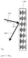
[0014] 도 2는 착용 가능 디스플레이 시스템의 예를 예시한다.
[0015] 도 3은 사용자에 대한 3차원 이미저리를 시뮬레이팅하기 위한 종래의 디스플레이 시스템을 예시한다.
[0016] 도 4는 다중 깊이 평면들을 사용하여 3-차원 이미저리를 시뮬레이팅하기 위한 접근법의 양상들을 예시한다.
[0017] 도 5a 내지 도 5c는 곡률의 반경과 초점 반경 간의 관계들을 예시한다.
[0018] 도 6은 이미지 정보를 사용자에게 출력하기 위한 도파관 스택의 예를 예시한다.
[0019] 도 7은 도파관에 의해 출력된 출사 빔들의 예를 예시한다.
[0020] 도 8은 각각의 깊이 평면이 다수의 상이한 컴포넌트 컬러들을 사용하여 형성된 이미지들을 포함하는 스택된 도파관 어셈블리의 예를 예시한다.
[0021] 도 9a는 인커플링 광학 엘리먼트를 각각 포함하는 스택된 도파관들의 세트의 예의 측 단면도를 예시한다.
[0022] 도 9b는 도 9a의 복수의 스택된 도파관들의 예의 사시도를 예시한다.
[0023] 도 9c는 도 9a 및 도 9b의 복수의 스택된 도파관들의 예의 하향식 평면도를 예시한다.
[0024] 도 10은 복수의 균일한 키랄 구조를 갖는 CLCG(cholesteric liquid crystal diffraction grating)의 예의 측 단면도를 예시한다.
[0025] 도 11은 측방향으로 상이하게 배열된 키랄 구조들을 갖는 CLCG의 예의 측 단면도를 예시한다.
[0026] 도 12는 오프-축 입사각에서 브래그-반사(Bragg reflection)를 위해 구성된 CLC 층의 예의 측 단면도를 예시한다.
[0027] 도 13a는 제1 오프-축 입사각에서 브래그-반사를 위해 구성되고 제1 나선형 피치를 갖는 CLC 층의 예의 측 단면도를 예시한다.
[0028] 도 13b는 제2 오프-축 입사각에서 브래그-반사를 위해 구성되고 제2 나선형 피치를 갖는 CLC 층의 예의 측 단면도를 예시한다.
[0029] 도 13c는 복수의 오프-축 입사각들 및 높은 회절 대역폭에서의 브래그-반사를 위해, 스택된 구성에서 상이한 나선형 피치들을 갖는, 도 13a 및 도 13b의 CLC 층들을 포함하는 CLCG의 예의 측 단면도를 예시한다.
[0030] 도 14는 복수의 오프-축 입사각들 및 높은 회절 대역폭에서의 브래그-반사를 위해 깊이 방향을 따라 상이한 나선형 피치들을 갖는 수직 구역들을 갖는 CLC 층을 포함하는 CLCG의 예의 측 단면도를 예시한다.
[0031] 도 15는 공간적으로 변동되는 브래그-반사를 위해 측방향을 따라 상이한 나선형 피치들을 갖는 측방향 구역들을 갖는 CLC 층을 포함하는 CLCG의 예의 측 단면도를 예시한다.
[0032] 도 16은 CLCG에 커플링되고 TIR(total internal reflection)에 의해 광을 전파시키도록 구성된 도파관을 포함하는 광학 광도파 디바이스의 예를 예시한다.
[0033] 도 17a는 CLCG에 커플링되고 TIR(total internal reflection)에 의해 파장을 갖는 광을 선택적으로 전파시키도록 구성된 도파관을 포함하는 광학 광도파 디바이스의 예를 예시한다.
[0034] 도 17b는 CLCG에 커플링되고 TIR(total internal reflection)에 의해 파장을 갖는 광을 선택적으로 전파시키도록 구성된 도파관을 각각 포함하는, 동일한 광학 경로의 복수의 광학 광도파 디바이스들의 예를 예시한다.
[0035] 도 17c는 CLCG에 커플링되고 TIR(total internal reflection)에 의해 파장을 갖는 광을 선택적으로 전파시키도록 구성된 도파관을 각각 포함하는, 동일한 광학 경로의 복수의 광학 광도파 디바이스들의 예를 예시한다.
[0036] 도 18은 복수의 CLCG들에 커플링되고 TIR(total internal reflection)에 의해 복수의 파장들을 갖는 광을 선택적으로 전파시키도록 구성된 공통 도파관을 포함하는 광학 광도파 디바이스의 예를 예시한다.
[0037] 도 19는 CLCG에 커플링되고 TIR(total internal reflection)에 의해 광을 전파시키도록 구성된 도파관을 포함하는 광학 광도파 디바이스의 예를 예시한다.
[0038] 도 20은 CLCG에 커플링된 도파관 및 편광 변환 반사기를 포함하는 광학 광도파 디바이스의 예를 예시하며, 여기서 CLCG는 입사광을 수신하도록 구성되고, 도파관은 TIR(total internal reflection)에 의해 CLCG로부터 브래그-반사된 광을 전파시키도록 구성된다.
[0039] 도 21a는 도 20의 광학 광도파 디바이스를 예시하며, 여기서, CLCG는 선형으로 편광되거나 또는 편광되지 않은 입사광을 수신하도록 구성되고 도파관은 CLCG로부터 브래그-반사된 광 및 TIR(total internal reflection)로 반사기에 의해 반사된 광을 전파시키도록 구성된다.
[0040] 도 21b는 도 20의 광학 광도파 디바이스를 예시하며, 여기서, CLCG는 직교 타원형 또는 원형 편광된 광 빔들로 편광되는 입사광을 수신하도록 구성되고 도파관은 CLCG로부터 브래그-반사된 광 및 TIR(total internal reflection)로 반사기에 의해 반사된 광을 전파시키도록 구성된다.
[0041] 도 22a는, 입사광 빔이 선형으로 편광되거나 편광되지 않은 조건 하에서, 제1 회전 방향을 갖는 키랄 구조들을 갖는 제1 CLC 층 및 제1 회전 방향에 상반되는 제2 회전 방향을 갖는 키랄 구조들을 갖는 제2 CLC 층을 포함하는, 공통 도파관에 커플링된 복수의 CLC 층들을 포함하는 광학 광도파 디바이스의 예를 예시한다.
[0042] 도 22b는 입사광이 직교 타원형 또는 원형 편광된 광 빔들로 편광되는 조건 하에서 도 22a의 광학 광도파 디바이스를 예시한다.
[0043] 도 22c는, 입사광 빔이 선형으로 편광되거나 편광되지 않은 조건 하에서, 제1 회전 방향을 갖는 키랄 구조들을 갖는 제1 CLC 층 및 제1 회전 방향에 상반되는 제2 회전 방향을 갖는 키랄 구조들을 갖는 제2 CLC 층을 포함하는, 2개의 CLC 층들 사이에 개재된 공통 도파관에 커플링된 복수의 CLC 층들을 포함하는 광학 광도파 디바이스의 예를 예시한다.
[0044] 도 23은 CLC(cholesteric liquid crystal) 오프-축 미러를 사용하여 착용자의 눈을 이미징하도록 구성된 전방-대면 카메라를 포함하는 이미징 시스템의 예를 예시한다.
[0045] 도 24a 내지 도 24f는 CLC 오프-축 미러를 사용하여 착용자의 눈을 이미징하도록 구성된 전방-대면 카메라를 포함하는 이미징 시스템의 예를 예시한다.
[0046] 도 24g 및 도 24h는 하나 이상의 CLC 오프-축 미러를 포함하는 복수의 세그먼트들(세그먼트들 각각은 상이한 광학 성질들을 가질 수 있음)을 포함하는 회절 광학 엘리먼트를 사용하여 착용자의 눈을 이미징하도록 구성된 전향(forward-facing) 카메라를 포함하는 이미징 시스템들의 예들을 예시한다.
[0047] 도 25는 CLCG에 커플링되고 TIR(total internal reflection)에 의해 광을 전파시키도록 구성된 도파관을 포함하는, 매우 넓은 시야에 대해 최적화된 예시적인 광학 광도파 디바이스를 예시한다.
[0048] 도 26은 CLCG에 커플링되고 TIR(total internal reflection)에 의해 광을 전파시키도록 구성된 도파관을 포함하는, 아웃커플링 광학 엘리먼트로서 구성되는 예시적인 광학 광도파 디바이스를 예시한다.
[0049] 도면들 전체에 걸쳐, 참조 번호들은 참조된 엘리먼트들 사이의 대응성(correspondence)을 표시하는 데 재사용될 수 있다. 도면들은 본원에서 설명된 예시적인 실시예들을 예시하기 위해 제공되며 본 개시내용의 범위를 제한하려는 의도는 아니다. 1 illustrates a user's view of AR through an augmented reality (AR) device.
2 illustrates an example of a wearable display system.
[0015] FIG. 3 illustrates a conventional display system for simulating three-dimensional imagery for a user.
[0016] FIG. 4 illustrates aspects of an approach for simulating three-dimensional imagery using multiple depth planes.
[0017] Figures 5A-5C illustrate relationships between the radius of curvature and the focal radius.
6 illustrates an example of a waveguide stack for outputting image information to a user.
7 illustrates an example of outgoing beams output by a waveguide.
[0020] FIG. 8 illustrates an example of a stacked waveguide assembly including images where each depth plane is formed using a number of different component colors.
[0021] FIG. 9A illustrates a cross-sectional side view of an example of a set of stacked waveguides each including an incoupling optical element.
[0022] FIG. 9B illustrates a perspective view of the example of the plurality of stacked waveguides of FIG. 9A.
[0023] FIG. 9C illustrates a top-down plan view of the example of the plurality of stacked waveguides of FIGS. 9A and 9B.
10 illustrates a cross-sectional side view of an example of a cholesteric liquid crystal diffraction grating (CLCG) having a plurality of uniform chiral structures.
[0025] FIG. 11 illustrates a cross-sectional side view of an example of a CLCG having chiral structures arranged differently in the lateral direction.
[0026] FIG. 12 illustrates a cross-sectional side view of an example of a CLC layer configured for Bragg-reflection at an off-axis angle of incidence.
[0027] FIG. 13A illustrates a cross-sectional side view of an example of a CLC layer configured for Bragg-reflection at a first off-axis angle of incidence and having a first helical pitch.
[0028] FIG. 13B illustrates a cross-sectional side view of an example of a CLC layer configured for Bragg-reflection at a second off-axis angle of incidence and having a second helical pitch.
[0029] FIG. 13C is an example side view of a CLCG comprising the CLC layers of FIGS. 13A and 13B with different helical pitches in a stacked configuration, for Bragg-reflection at multiple off-axis angles of incidence and high diffraction bandwidth. Illustrate the cross section.
[0030] FIG. 14 illustrates a side cross-sectional view of an example of a CLCG comprising a CLC layer having vertical zones with multiple off-axis angles of incidence and different helical pitches along the depth direction for Bragg-reflection at a high diffraction bandwidth. .
[0031] FIG. 15 illustrates a cross-sectional side view of an example of a CLCG comprising a CLC layer having lateral zones with different helical pitches along the lateral direction for spatially varied Bragg-reflection.
[0032] FIG. 16 illustrates an example of an optical light waveguide device that includes a waveguide coupled to a CLCG and configured to propagate light by total internal reflection (TIR).
[0033] FIG. 17A illustrates an example of an optical light waveguide device including a waveguide coupled to a CLCG and configured to selectively propagate light having a wavelength by total internal reflection (TIR).
[0034] FIG. 17B illustrates an example of a plurality of optical light waveguide devices of the same optical path, each comprising a waveguide coupled to a CLCG and configured to selectively propagate light having a wavelength by total internal reflection (TIR) do.
[0035] FIG. 17C illustrates an example of a plurality of optical light waveguide devices of the same optical path, each comprising a waveguide coupled to a CLCG and configured to selectively propagate light having a wavelength by total internal reflection (TIR) do.
[0036] FIG. 18 illustrates an example of an optical lightguide device including a common waveguide coupled to a plurality of CLCGs and configured to selectively propagate light having a plurality of wavelengths by total internal reflection (TIR).
[0037] FIG. 19 illustrates an example of an optical light waveguide device that includes a waveguide coupled to a CLCG and configured to propagate light by total internal reflection (TIR).
[0038] FIG. 20 illustrates an example of an optical light waveguide device comprising a polarization converting reflector and a waveguide coupled to a CLCG, where the CLCG is configured to receive incident light, and the waveguide is configured to transmit light to the CLCG by total internal reflection (TIR). configured to propagate Bragg-reflected light from
[0039] FIG. 21A illustrates the optical light waveguide device of FIG. 20, where the CLCG is configured to receive incident light, either linearly polarized or unpolarized, and the waveguide comprises Bragg-reflected light from the CLCG and total internal reflection (TIR). ) to propagate the light reflected by the reflector.
[0040] FIG. 21B illustrates the optical light waveguide device of FIG. 20, where the CLCG is configured to receive incident light that is polarized into orthogonal elliptical or circularly polarized light beams and the waveguide comprises Bragg-reflected light from the CLCG and TIR ( It is configured to propagate light reflected by the reflector with total internal reflection.
[0041] FIG. 22A shows a first CLC layer having chiral structures having a first rotational direction and a chiral structure having a second rotational direction opposite to the first rotational direction under conditions where an incident light beam is linearly polarized or unpolarized. An example of an optical light guide device including a plurality of CLC layers coupled to a common waveguide, including a second CLC layer having .
[0042] FIG. 22B illustrates the optical lightguide device of FIG. 22A under the condition that incident light is polarized into orthogonal elliptical or circularly polarized light beams.
[0043] FIG. 22C shows a first CLC layer having chiral structures having a first rotational direction and a chiral structure having a second rotational direction opposite to the first rotational direction under conditions where an incident light beam is linearly polarized or unpolarized. An example of an optical light guide device including a plurality of CLC layers coupled to a common waveguide interposed between two CLC layers, including a second CLC layer having .
[0044] FIG. 23 illustrates an example of an imaging system that includes a front-facing camera configured to image a wearer's eye using a cholesteric liquid crystal (CLC) off-axis mirror.
[0045] FIGS. 24A-24F illustrate an example of an imaging system that includes a front-facing camera configured to image a wearer's eye using a CLC off-axis mirror.
[0046] FIGS. 24G and 24H are imaging a wearer's eye using a diffractive optical element comprising a plurality of segments (each of which may have different optical properties) comprising one or more CLC off-axis mirrors. Examples of imaging systems that include a forward-facing camera configured to
[0047] FIG. 25 illustrates an example optical light waveguide device optimized for a very wide field of view, comprising a waveguide coupled to a CLCG and configured to propagate light by total internal reflection (TIR).
[0048] FIG. 26 illustrates an exemplary optical lightguide device configured as an outcoupling optical element, including a waveguide coupled to a CLCG and configured to propagate light by total internal reflection (TIR).
[0049] Throughout the drawings, reference numbers may be reused to indicate correspondence between referenced elements. The drawings are provided to illustrate exemplary embodiments described herein and are not intended to limit the scope of the present disclosure.
[0050] AR 시스템들은 사용자가 자신 주위의 세계를 계속해서 볼 수 있게 하면서, 가상 콘텐츠를 사용자 또는 뷰어에 디스플레이할 수 있다. 바람직하게는, 이 콘텐츠는 사용자의 눈들에 이미지 정보를 프로젝팅하는, 예컨대, 안경류의 부분으로서 머리-장착 디스플레이 상에 디스플레이된다. 게다가, 디스플레이는 또한 주변 환경의 뷰를 허용하기 위해 주변 환경으로부터 사용자의 눈으로 광을 투과시킬 수 있다. 본원에서 사용되는 바와 같이, "머리-장착" 디스플레이는 뷰어의 머리 상에 장착될 수 있는 디스플레이라는 것이 인지될 것이다. [0050] AR systems can display virtual content to a user or viewer while allowing the user to continue seeing the world around them. Preferably, this content is displayed on a head-mounted display that projects image information to the user's eyes, eg, as part of eyewear. Additionally, the display may also transmit light from the surrounding environment to the user's eyes to allow viewing of the surrounding environment. As used herein, it will be appreciated that a “head-mounted” display is a display that can be mounted on a viewer's head.
[0051] 도 2는 웨어러블 디스플레이 시스템(80)의 예를 예시한다. 디스플레이 시스템(80)은 디스플레이(62), 및 그 디스플레이(62)의 기능을 지원하기 위한 다양한 기계 및 전자 모듈들 및 시스템들을 포함한다. 디스플레이(62)는, 디스플레이 시스템 사용자 또는 뷰어(60)에 의해 착용 가능하고 사용자(60)의 눈들의 전방에 디스플레이(62)를 포지셔닝하도록 구성된 프레임(64)에 커플링될 수 있다. 디스플레이(62)는 일부 실시예들에서, 안경류(eyewear)로 고려될 수 있다. 일부 실시예들에서, 스피커(66)는 프레임(64)에 커플링되고 사용자(60)의 외이도에 인접하게 포지셔닝된다(일부 실시예들에서, 도시되지 않은 다른 스피커가 사용자의 다른 외이도에 인접하게 포지셔닝되어 스테레오/형상화가능(shapeable) 사운드 제어를 제공함). 일부 실시예들에서, 디스플레이 시스템은 또한 하나 이상의 마이크로폰들(67) 또는 사운드를 검출하기 위한 다른 디바이스들을 포함할 수 있다. 일부 실시예들에서, 마이크로폰은 사용자가 시스템(80)에 입력들 또는 커맨드들(예컨대, 음성 메뉴 커맨드들의 선택, 자연어 질문 등)을 제공할 수 있도록 구성되고, 그리고/또는 다른 사람들(예컨대, 유사한 디스플레이 시스템들의 다른 사용자들)과의 오디오 통신을 허용할 수 있다. 마이크로폰은 또한, 오디오 데이터를 계속해서 수집하기 위해(예컨대, 사용자 및/또는 환경으로부터 수동적으로 수집하기 위해) 주변 센서로서 구성될 수 있다. 이러한 오디오 데이터는 사용자 사운드들, 이를테면, 거친 숨, 또는 환경 사운드들, 이를테면, 근처의 이벤트를 나타내는 큰 굉음(loud bang)을 포함할 수 있다. 디스플레이 시스템은 또한, 프레임(64)과 별개이고 사용자(60)의 신체(예컨대, 사용자(60)의 머리, 몸통, 손발(extremity) 등)에 부착될 수 있는 주변 센서(30a)를 포함할 수 있다. 주변 센서(30a)는 본원에서 추가로 설명된 바와 같이, 일부 실시예들에서, 사용자(60)의 생리적인 상태를 특징화하는 데이터를 취득하도록 구성될 수 있다. 예컨대, 센서(30a)는 전극일 수 있다. 2 illustrates an example of a
[0052] 도 2를 계속 참조하면, 디스플레이(62)는, 다양한 구성들로 장착될 수 있는, 예컨대, 프레임(64)에 고정적으로 부착되거나, 사용자에 의해 착용된 헬멧 또는 모자에 고정적으로 부착되거나, 헤드폰들에 임베딩되거나, 그렇지 않으면 사용자(60)에게 제거 가능하게 부착되는(예컨대, 백팩(backpack)-스타일 구성으로, 벨트-커플링 스타일 구성으로) 로컬 데이터 프로세싱 모듈(70)에 통신 링크(68)에 의해, 예컨대, 유선 리드 또는 무선 연결성에 의해, 동작 가능하게 커플링된다. 유사하게, 센서(30a)는 통신 링크(30b), 예컨대, 유선 리드 또는 무선 연결성에 의해 로컬 프로세서 및 데이터 모듈(70)에 동작 가능하게 커플링될 수 있다. 로컬 프로세싱 및 데이터 모듈(70)은 하드웨어 프로세서뿐 아니라, 디지털 메모리 예컨대, 비-휘발성 메모리(예컨대, 플래시 메모리 또는 하드 디스크 드라이브들)를 포함할 수 있고, 이 둘 모두는 데이터의 프로세싱, 캐싱(caching) 및 저장을 보조하기 위해 활용될 수 있다. 데이터는 a) 센서들(예컨대 프레임(64)에 동작 가능하게 커플링되거나 그렇지 않으면 사용자(60)에게 부착될 수 있음), 예컨대, 이미지 캡처 디바이스들(예컨대, 카메라들), 마이크로폰들, 관성 측정 유닛들, 가속도계들, 컴파스(compass)들, GPS 유닛들, 라디오 디바이스들, 자이로(gyro)들 및/또는 본원에서 개시된 다른 센서들로부터 캡처되고; 및/또는 b) 원격 프로세싱 모듈(72) 및/또는 원격 데이터 리포지토리(repository)(74)(가상 콘텐츠에 관련된 데이터를 포함함)를 사용하여 취득 및/또는 프로세싱되는 (어쩌면, 이러한 프로세싱 또는 리트리벌(retrieval) 후 디스플레이(62)에 전달하기 위한) 데이터를 포함한다. 로컬 프로세싱 및 데이터 모듈(70)은 통신 링크들(76, 78)에 의해, 예컨대, 유선 또는 무선 통신 링크들을 통하여, 원격 프로세싱 모듈(72) 및 원격 데이터 리포지토리(74)에 동작 가능하게 커플링될 수 있어서, 이들 원격 모듈들(72, 74)은 서로 동작 가능하게 커플링되고 로컬 프로세싱 및 데이터 모듈(70)에 대한 자원들로서 이용 가능하다. 일부 실시예들에서, 로컬 프로세싱 및 데이터 모듈(70)은 이미지 캡처 디바이스들, 마이크로폰들, 관성 측정 유닛들, 가속도계들, 컴퍼스들, GPS 유닛들, 라디오 디바이스들 및/또는 자이로들 중 하나 이상을 포함할 수 있다. 일부 다른 실시예들에서, 이들 센서들 중 하나 이상은 프레임(64)에 부착될 수 있거나, 또는 유선 또는 무선 통신 통로들에 의해 로컬 프로세싱 및 데이터 모듈(70)과 통신하는 자립형 구조들일 수 있다. [0052] With continued reference to FIG. 2,
[0053] 도 2를 계속 참조하면, 일부 실시예들에서, 원격 프로세싱 모듈(72)은 데이터 및/또는 이미지 정보를 분석 및 프로세싱하도록 구성된 하나 이상의 프로세서들을 포함할 수 있다. 일부 실시예들에서, 원격 데이터 리포지토리(74)는 "클라우드" 자원 구성에서 인터넷 또는 다른 네트워킹 구성을 통하여 이용 가능할 수 있는 디지털 데이터 저장 설비를 포함할 수 있다. 일부 실시예들에서, 원격 데이터 리포지토리(74)는 정보, 예컨대, 증강 현실 콘텐츠를 생성하기 위한 정보를 로컬 프로세싱 및 데이터 모듈(70) 및/또는 원격 프로세싱 모듈(72)에 제공하는 하나 이상의 원격 서버들을 포함할 수 있다. 일부 실시예들에서, 모든 데이터는 저장되고 모든 컴퓨테이션들은 로컬 프로세싱 및 데이터 모듈에서 수행되어, 원격 모듈로부터 완전히 자율적인 사용을 허용한다. [0053] With continued reference to FIG. 2, in some embodiments,
[0054] "3-차원" 또는 "3-D"인 것으로서 이미지의 지각은 뷰어의 각각의 눈에 이미지의 약간 상이한 프리젠테이션들을 제공함으로써 달성될 수 있다. 도 3은 사용자에 대한 3차원 이미저리를 시뮬레이팅하기 위한 종래의 디스플레이 시스템을 예시한다. 2개의 별개의 이미지들(5 및 7)(각각의 눈(4 및 6)에 대해 하나씩)이 사용자에게 출력된다. 이미지들(5, 7)은 뷰어의 시선과 평행한 광학 또는 z-축을 따라 거리(10) 만큼 눈들(4, 6)로부터 이격된다. 이미지들(5, 7)은 편평하고 눈들(4, 6)은 단일 원근조절된 상태를 가정함으로써 이미지들에 포커싱될 수 있다. 그러한 시스템들은 조합된 이미지에 대한 스케일 및/또는 깊이의 지각을 제공하기 위하여 이미지들(5, 7)을 조합하는데 인간 시각 시스템에 의존한다. [0054] The perception of an image as being "three-dimensional" or "3-D" may be achieved by presenting slightly different presentations of the image to each eye of a viewer. 3 illustrates a conventional display system for simulating three-dimensional imagery for a user. Two
[0055] 그러나, 인간 시각 시스템은 더 복잡하고 현실적인 깊이의 지각을 제공하는 것이 더 어렵다는 것이 인지될 것이다. 예컨대, 종래의 3-D 디스플레이 시스템들의 많은 뷰어들은 그런 시스템들이 불편하다는 것을 발견하거나, 깊이 감을 전혀 지각하지 못할 수 있다. 이론에 의해 제한됨이 없이, 객체의 뷰어들은 이접운동 및 원근조절의 조합으로 인해 객체를 3-차원인 것으로 지각할 수 있다고 여겨진다. 서로에 대한 두 눈들의 이접운동(vergence) 움직임들(즉, 동공들이 객체를 응시하기 위해 눈들의 시선들을 수렴하도록 서로를 향해 또는 서로 멀어지게 움직이도록 하는 눈들의 회전)은 눈들의 동공들 및 렌즈들의 포커싱(또는 원근조절)과 밀접하게 연관된다. 정상 조건들하에서, 하나의 객체로부터 상이한 거리에 있는 다른 객체로 포커스를 변화시키기 위하여, 눈들의 렌즈들의 포커스를 변화시키거나, 또는 눈들을 원근조절하는 것은 "원근조절-이접운동 반사(accommodation-vergence reflex)"로서 알려진 관계하에서, 동일한 거리에 대한 이접운동에서의 매칭하는 변화는 물론 동공 팽창 및 수축을 자동으로 유발할 것이다. 마찬가지로, 이접운동에서의 변경은 정상 조건들하에서, 렌즈 형상 및 동공 사이즈의, 원근조절에서의 매칭하는 변경을 트리거할 것이다. 본원에서 언급되는 바와 같이, 다수의 입체 또는 "3-D" 디스플레이 시스템들은, 3-차원 관점이 이 인간 시각 시스템에 의해 지각되도록 각각의 눈에 약간 상이한 프리젠테이션들(그리고 따라서, 약간 상이한 이미지들)을 사용하여 장면을 디스플레이한다. 그러나, 그러한 시스템들은 많은 뷰어들에게 불편한데, 그 이유는 다른 것들 중에서, 그러한 시스템들이 단순히 장면의 상이한 프리젠테이션을 제공하지만, 눈들이 단일 원근조절된 상태에서 모든 이미지 정보를 보고, 그리고 원근조절-이접운동 반사에 반하여 작동하기 때문이다. 원근조절과 이접운동 사이의 더 양호한 매칭을 제공하는 디스플레이 시스템들은, 증가된 착용 지속기간 및 결국, 진단 및 치료 프로토콜들에 대한 준수에 기여하는, 3-차원 이미저리의 더 현실적이고 편안한 시뮬레이션들을 형성할 수 있다. [0055] However, it will be appreciated that the human visual system is more complex and more difficult to provide realistic depth perception. For example, many viewers of conventional 3-D display systems find such systems uncomfortable, or may not perceive depth at all. Without being limited by theory, it is believed that viewers of an object may perceive the object as being three-dimensional due to a combination of disjunction and accommodation. The vergence movements of the two eyes relative to each other (i.e., the rotation of the eyes to move the pupils towards or away from each other to converge their gazes to gaze at an object) are the movements of the pupils of the eyes and the lens It is closely related to the focusing (or accommodation) of people. Under normal conditions, changing the focus of the lenses of the eyes, or accommodating the eyes, to change focus from one object to another at a different distance, is known as the "accommodation-vergence reflex". Under a relationship known as “reflex”, matching changes in disjunctive motion over the same distance will automatically cause pupillary dilation and constriction as well. Likewise, a change in vergence will trigger a matching change in accommodation, of lens shape and pupil size, under normal conditions. As referred to herein, a number of stereoscopic or “3-D” display systems provide slightly different presentations (and thus slightly different images) to each eye such that a three-dimensional perspective is perceived by the human visual system. ) to display the scene. However, such systems are inconvenient for many viewers because, among other things, such systems simply provide a different presentation of a scene, but the eyes see all image information in a single accommodation, and accommodation-disjunction. This is because it works against the motor reflex. Display systems that provide better matching between accommodation and displacement will create more realistic and comfortable simulations of three-dimensional imagery, contributing to increased wearing duration and, consequently, adherence to diagnostic and treatment protocols. can
[0056] 도 4는 다중 깊이 평면들을 사용하여 3-차원 이미저리를 시뮬레이팅하기 위한 접근법의 양상들을 예시한다. 도 4를 참조하면, z-축 상에서 눈들(4, 6)로부터의 다양한 거리들에 있는 객체들은, 이들 객체들이 인 포커싱(in focus)되도록 눈들(4, 6)에 의해 원근조절된다. 눈들(4 및 6)은 z-축을 따라 상이한 거리들에 있는 객체들에 포커싱을 맞추게 하는 특정 원근조절된 상태들을 가정한다. 결과적으로, 특정 원근조절된 상태는 연관된 초점 거리를 갖는 깊이 평면들(14) 중 특정한 하나의 깊이 평면과 연관되는 것으로 말할 수 있어서, 특정 깊이 평면의 객체들 또는 객체들의 부분들은, 눈이 해당 깊이 평면에 대해 원근조절된 상태에 있을 때 인 포커싱된다. 일부 실시예들에서, 3-차원 이미저리는 눈들(4, 6) 각각에 대해 이미지의 상이한 프리젠테이션들을 제공함으로써, 그리고 또한 깊이 평면들 각각에 대응하는 이미지의 상이한 프리젠테이션들을 제공함으로써 시뮬레이팅될 수 있다. 예시의 명확성을 위해 별개인 것으로 도시되지만, 눈들(4, 6)의 시야들은 예컨대, z-축을 따른 거리가 증가함에 따라 겹쳐질 수 있다는 것이 인지될 것이다. 게다가, 예시의 용이함을 위해 평평한 것으로 도시되지만, 깊이 평면의 윤곽들은 물리적 공간에서 만곡될 수 있어서, 깊이 평면의 모든 특징들은 특정 원근조절된 상태에서 눈과 인 포커싱된다는 것이 인지될 것이다. [0056] FIG. 4 illustrates aspects of an approach for simulating 3-dimensional imagery using multiple depth planes. Referring to Figure 4, objects at various distances from
[0057] 객체와 눈(4 또는 6) 간의 거리는 또한, 그 눈으로 볼 때, 그 객체로부터 광의 발산(divergence)의 양을 변화시킬 수 있다. 도 5a 내지 도 5c는 광선들의 거리와 발산 간의 관계들을 예시한다. 객체와 눈(4) 간의 거리는, 거리가 감소하는 순서로 R1, R2 및 R3에 의해 표현된다. 도 5a 내지 도 5c에 도시된 바와 같이, 광선들은, 객체에 대한 거리가 감소함에 따라 더 많이 발산하게 된다. 거리가 증가함에 따라, 광선들은 더욱 시준된다. 다른 말로 하면, 포인트(객체 또는 객체의 일부)에 의해 생성된 광 필드가 구체 파면 곡률을 가지는 것으로 말해질 수 있고, 구체 파면 곡률은, 포인트가 사용자의 눈으로부터 얼마나 멀리 떨어져 있는지의 함수이다. 곡률은 객체와 눈(4) 간의 거리가 감소함에 따라 증가한다. 결과적으로, 상이한 깊이 평면들에서, 광선들의 발산 정도는 또한 상이하고, 발산 정도는, 깊이 평면들과 뷰어의 눈(4) 간의 거리가 감소함에 따라 증가한다. 단지 하나의 눈(4)이 도 5a 내지 도 5c 및 본원의 다른 도면들에서 예시의 명확성을 위해 예시되지만, 눈(4)에 대한 논의들이 뷰어의 양쪽 눈들(4 및 6)에 적용될 수 있다는 것이 인지될 것이다. [0057] The distance between an object and the
[0058] 이론에 의해 제한됨이 없이, 인간 눈이 통상적으로 깊이 지각을 제공하기 위하여 유한 수의 깊이 평면들을 해석할 수 있다고 여겨진다. 결과적으로, 지각된 깊이의 매우 믿을 만한 시뮬레이션은, 눈에, 이들 제한된 수의 깊이 평면들 각각에 대응하는 이미지의 상이한 프리젠테이션들을 제공함으로써 달성될 수 있다. 상이한 프리젠테이션들이 뷰어의 눈들에 의해 별개로 포커싱될 수 있고, 그리하여, 상이한 깊이 평면 상에 로케이팅되는 장면에 대한 상이한 이미지 특징들에 포커스를 맞추도록 요구되는 눈의 원근조절에 기초하여 그리고/또는 상이한 깊이 평면들 상의 상이한 이미지 특징들이 아웃 포커스(out of focus)되는 것을 관찰하는 것에 기초하여 깊이 단서들을 사용자에게 제공하는 것을 돕는다. [0058] Without being limited by theory, it is believed that the human eye can typically interpret a finite number of depth planes to provide depth perception. Consequently, a highly reliable simulation of perceived depth can be achieved by presenting to the eye different presentations of the image corresponding to each of these limited number of depth planes. Different presentations may be separately focused by the viewer's eyes, thus based on eye accommodation required to focus on different image features for a scene located on different depth planes and/or Helps provide depth clues to the user based on observing that different image features on different depth planes are out of focus.
[0059] 도 6은 이미지 정보를 사용자에게 출력하기 위한 도파관 스택의 예를 예시한다. 디스플레이 시스템(1000)은 복수의 도파관들(1182, 1184, 1186, 1188, 1190)을 사용하여 3-차원 지각을 눈/뇌에 제공하기 위하여 활용될 수 있는 도파관들의 스택, 또는 스택된 도파관 어셈블리(1178)를 포함한다. 일부 실시예들에서, 디스플레이 시스템(1000)은 도 2의 시스템(80)이고, 도 6은 그 시스템(80)의 일부 부분들을 더 상세히 개략적으로 보여준다. 예컨대, 도파관 어셈블리(1178)는 도 2의 디스플레이(62)의 부분일 수 있다. 디스플레이 시스템(1000)은 일부 실시예들에서 광 필드(light field) 디스플레이로서 간주될 수 있다는 것이 인지될 것이다. 6 illustrates an example of a waveguide stack for outputting image information to a user.
[0060] 도 6을 계속 참조하면, 도파관 어셈블리(1178)는 또한 도파관들 사이에 복수의 특징들(1198, 1196, 1194, 1192)을 포함할 수 있다. 일부 실시예들에서, 특징들(1198, 1196, 1194, 1192)은 하나 이상의 렌즈들일 수 있다. 도파관들(1182, 1184, 1186, 1188, 1190) 및/또는 복수의 렌즈들(1198, 1196, 1194, 1192)은 다양한 레벨들의 파면 곡률 또는 광선 발산으로 이미지 정보를 눈에 전송하도록 구성될 수 있다. 각각의 도파관 레벨은 특정 깊이 평면과 연관될 수 있고 그 깊이 평면에 대응하는 이미지 정보를 출력하도록 구성될 수 있다. 이미지 주입 디바이스들(1200, 1202, 1204, 1206, 1208)은 도파관들에 대한 광의 소스로서 기능할 수 있고, 이미지 정보를 도파관들(1182, 1184, 1186, 1188, 1190)에 주입하기 위하여 활용될 수 있으며, 도파관들 각각은, 본원에 설명된 바와 같이, 눈(4)을 향하여 출력하기 위해 각각의 개별 도파관에 걸쳐 인입 광을 분산시키도록 구성될 수 있다. 광은 이미지 주입 디바이스들(1200, 1202, 1204, 1206, 1208)의 출력 표면(1300, 1302, 1304, 1306, 1308)을 나가고 도파관들(1182, 1184, 1186, 1188, 1190)의 대응하는 입력 표면(1382, 1384, 1386, 1388, 1390)에 주입된다. 일부 실시예들에서, 입력 표면들(1382, 1384, 1386, 1388, 1390) 각각은 대응하는 도파관의 에지일 수 있거나, 또는 대응하는 도파관의 주 표면의 일부일 수 있다(즉, 도파관 표면들 중 하나는 직접적으로 세계(1144) 또는 뷰어의 눈(4)을 향함). 일부 실시예들에서, 단일 광 빔(예컨대, 시준된 빔)은 특정 도파관과 연관된 깊이 평면에 대응하는 특정 각도들(및 발산의 양들)로 눈(4)을 향하여 지향되는 시준된 클론 빔(cloned collimated beam)들의 전체 필드를 출력하기 위하여 각각의 도파관으로 주입될 수 있다. 일부 실시예들에서, 이미지 주입 디바이스들(1200, 1202, 1204, 1206, 1208) 중 하나의 이미지 주입 디바이스가 복수(예컨대, 3개)의 도파관들(1182, 1184, 1186, 1188, 1190)과 연관되고 그에 광을 주입할 수 있다. [0060] With continued reference to FIG. 6, the
[0061] 일부 실시예들에서, 이미지 주입 디바이스들(1200, 1202, 1204, 1206, 1208)은 각각 대응하는 도파관(1182, 1184, 1186, 1188, 1190)에 주입을 위한 이미지 정보를 각각 생성하는 이산 디스플레이들이다. 일부 다른 실시예들에서, 이미지 주입 디바이스들(1200, 1202, 1204, 1206, 1208)은 예컨대, 이미지 정보를 하나 이상의 광학 도관들(예컨대, 광섬유 케이블들)을 통하여 이미지 주입 디바이스들(1200, 1202, 1204, 1206, 1208) 각각에 파이핑(pipe)할 수 있는 단일 멀티플렉싱된 디스플레이의 출력 단부들이다. 이미지 주입 디바이스들(1200, 1202, 1204, 1206, 1208)에 의해 제공되는 이미지 정보는 상이한 파장들 또는 컬러들(예컨대, 본원에서 논의된 바와 같이 상이한 컴포넌트 컬러들)의 광을 포함할 수 있다는 것이 인지될 것이다. [0061] In some embodiments, the
[0062] 일부 실시예들에서, 도파관들(1182, 1184, 1186, 1188, 1190)로 주입된 광은 LED(light emitting diode)와 같은 광 이미터를 포함할 수 있는 광 모듈(2040)을 포함하는 광 프로젝터 시스템(2000)에 의해 제공된다. 광 모듈(2040)로부터의 광은 빔 분할기(2050)를 통해 광 변조기(2030), 예컨대, 공간 광 변조기에 지향되고 그에 의해 수정될 수 있다. 광 변조기(2030)는 도파관들(1182, 1184, 1186, 1188, 1190) 내로 주입되는 광의 지각된 세기를 변화시키도록 구성될 수 있다. 공간 광 변조기들의 예들은, LCOS(liquid crystal on silicon) 디스플레이들을 포함하는 LCD(liquid crystal display)들을 포함한다. [0062] In some embodiments, light injected into
[0063] 일부 실시예들에서, 디스플레이 시스템(1000)은 광을 다양한 패턴들(예컨대, 래스터 스캔, 나선형 스캔, 리사주(Lissajous) 패턴 등)로 하나 이상의 도파관들(1182, 1184, 1186, 1188, 1190) 내로 그리고 궁극적으로 뷰어의 눈(4)으로 프로젝팅하도록 구성된 하나 이상의 스캐닝 섬유들을 포함하는 스캐닝 섬유 디스플레이일 수 있다. 일부 실시예들에서, 예시된 이미지 주입 디바이스들(1200, 1202, 1204, 1206, 1208)은 하나 또는 복수의 도파관들(1182, 1184, 1186, 1188, 1190) 내로 광을 주입하도록 구성된 단일 스캐닝 섬유 또는 스캐닝 섬유들의 번들(bundle)들을 개략적으로 표현할 수 있다. 일부 다른 실시예들에서, 예시된 이미지 주입 디바이스들(1200, 1202, 1204, 1206, 1208)은 복수의 스캐닝 섬유들 또는 스캐닝 섬유들의 복수의 번들들을 개략적으로 표현할 수 있으며, 이들 각각은 도파관들(1182, 1184, 1186, 1188, 1190) 중 연관된 하나 내로 광을 주입하도록 구성된다. 하나 이상의 광섬유들이 광 모듈(2040)로부터 하나 이상의 도파관들(1182, 1184, 1186, 1188, 1190)로 광을 송신하도록 구성될 수 있다는 것이 인지될 것이다. 예컨대, 스캐닝 섬유에서 나오는 광을 하나 이상의 도파관들(1182, 1184, 1186, 1188, 1190)로 재지향시키도록, 스캐닝 섬유 또는 섬유들과 하나 이상의 도파관들(1182, 1184, 1186, 1188, 1190) 사이에 하나 이상의 개재된 광학 구조들이 제공될 수 있다는 것이 인지될 것이다. [0063] In some embodiments,
[0064] 제어기(1210)는 이미지 주입 디바이스들(1200, 1202, 1204, 1206, 1208), 광 소스(2040) 및 광 변조기(2030)의 동작을 포함한, 스택된 도파관 어셈블리(1178)의 하나 이상의 도파관들의 동작을 제어한다. 일부 실시예들에서, 제어기(1210)는 로컬 데이터 프로세싱 모듈(70)의 부분이다. 제어기(1210)는 예컨대, 본원에서 개시된 다양한 방식들 중 임의의 방식에 따라 도파관들(1182, 1184, 1186, 1188, 1190)에 대한 이미지 정보의 타이밍 및 제공을 조절하는 프로그래밍(예컨대, 비-일시적 매체의 명령들)을 포함한다. 일부 실시예들에서, 제어기는 단일 통합 디바이스, 또는 유선 또는 무선 통신 채널들에 의해 연결되는 분산 시스템일 수 있다. 제어기(1210)는 일부 실시예들에서, 프로세싱 모듈들(70 또는 72)(도 1)의 부분일 수 있다. [0064]
[0065] 도 6을 계속 참조하면, 도파관들(1182, 1184, 1186, 1188, 1190)은 TIR(total internal reflection)에 의해 각각의 개별 도파관 내에서 광을 전파시키도록 구성될 수 있다. 도파관들(1182, 1184, 1186, 1188, 1190)은 각각 평면형이거나 다른 형상(예컨대, 곡선)을 가질 수 있으며, 주 최상부 및 최하부 표면들 및 이들 주 최상부와 최하부 표면들 사이에서 연장되는 에지들을 갖는다. 예시된 구성에서, 도파관들(1182, 1184, 1186, 1188, 1190)은 이미지 정보를 눈(4)에 출력하기 위해 각각의 개별 도파관 내에서 전파되는 광을 도파관 밖으로 재지향시킴으로써 도파관 밖으로 광을 추출하도록 구성된 아웃커플링 광학 엘리먼트들(1282, 1284, 1286, 1288, 1290)을 각각 포함할 수 있다. 추출된 광은 아웃커플링된 광으로서 또한 지칭될 수 있고, 아웃커플링 광학 엘리먼트들은 또한 광 추출 광학 엘리먼트들로서 지칭될 수 있다. 추출된 광 빔은, 도파관 내에서 전파되는 광이 광 추출 광학 엘리먼트에 부딪치는 위치들에서 도파관에 의해 출력된다. 아웃커플링 광학 엘리먼트들(1282, 1284, 1286, 1288, 1290)은 예컨대, 본원에서 추가로 논의되는 바와 같이, 회절성 광학 특징들을 포함하는 격자들일 수 있다. 설명의 용이함 및 도면 명확성을 위하여 도파관들(1182, 1184, 1186, 1188, 1190)의 최하부 주 표면들에 배치된 것으로 예시되지만, 일부 실시예들에서, 아웃커플링 광학 엘리먼트들(1282, 1284, 1286, 1288, 1290)은 본원에서 추가로 논의되는 바와 같이, 최상부 및/또는 최하부 주 표면들에 배치될 수 있고, 그리고/또는 도파관들(1182, 1184, 1186, 1188, 1190)의 볼륨에 직접 배치될 수 있다. 일부 실시예들에서, 아웃커플링 광학 엘리먼트들(1282, 1284, 1286, 1288, 1290)은 도파관들(1182, 1184, 1186, 1188, 1190)을 형성하기 위해 투명 기판에 부착된 재료 층에 형성될 수 있다. 일부 다른 실시예들에서, 도파관들(1182, 1184, 1186, 1188, 1190)은 재료의 모놀리식 피스(piece)일 수 있고 아웃커플링 광학 엘리먼트들(1282, 1284, 1286, 1288, 1290)은 재료의 해당 피스의 표면 상에 그리고/또는 그 내부에 형성될 수 있다. [0065] With continued reference to FIG. 6,
[0066] 도 6을 계속 참조하면, 본원에 논의된 바와 같이, 각각의 도파관(1182, 1184, 1186, 1188, 1190)은 특정 깊이 평면에 대응하는 이미지를 형성하기 위해 광을 출력하도록 구성된다. 예컨대, 눈에 가장 가까운 도파관(1182)은, 그러한 도파관(1182)에 주입된 시준된 광을 눈(4)에 전달하도록 구성될 수 있다. 시준된 광은 광학 무한대 초점 평면을 나타낼 수 있다. 위의 다음 도파관(1184)은, 시준된 광이 눈(4)에 도달할 수 있기 전에 제1 렌즈(1192)(예컨대, 네거티브 렌즈)를 통과하는 시준된 광을 전송하도록 구성될 수 있고; 그러한 제1 렌즈(1192)는 약간 볼록한 파면 곡률을 생성하도록 구성될 수 있어서, 눈/뇌는 위의 다음 도파관(1184)으로부터 오는 광을, 광학적 무한대로부터 눈(4)을 향하여 안쪽으로 더 가까운 제1 초점 평면으로부터 오는 것으로 해석한다. 유사하게, 위의 제3 도파관(1186)은 자신의 출력 광을 눈(4)에 도달하기 전에 제1 (1192) 및 제2 (1194) 렌즈들 둘 모두를 통과시키고; 제1 (1192) 및 제2 (1194) 렌즈들의 조합된 광 파워(optical power)는 다른 증분 양의 파면 곡률을 생성하도록 구성될 수 있어서, 눈/뇌는 제3 도파관(1186)으로부터 오는 광을, 위의 다음 도파관(1184)으로부터의 광보다는 광학적 무한대로부터 사람을 향하여 안쪽으로 훨씬 더 가까운 제2 초점 평면으로부터 오는 것으로 해석한다. [0066] With continued reference to FIG. 6, and as discussed herein, each
[0067] 다른 도파관 층들(1188, 1190) 및 렌즈들(1196, 1198)은 유사하게 구성되는데, 스택에서 가장 높은 도파관(1190)은 자신의 출력을, 사람과 가장 가까운 초점 평면을 나타내는 어그리게이트 초점 전력에 대해 자신과 눈 사이의 렌즈들 모두를 통하여 전송한다. 스택된 도파관 어셈블리(1178)의 다른 측 상에서 세계(1144)로부터 오는 광을 보거나/해석할 때 렌즈들(1198, 1196, 1194, 1192)의 스택을 보상하기 위하여, 보상 렌즈 층(1180)은 아래의 렌즈 스택(1198, 1196, 1194, 1192)의 어그리게이트 전력을 보상하기 위하여 스택의 최상부에 배치될 수 있다. 이러한 구성은 이용 가능한 도파관/렌즈 쌍들이 존재하는 만큼 많은 지각된 초점 평면들을 제공한다. 도파관들의 아웃커플링 광학 엘리먼트들 및 렌즈들의 포커싱 양상들 둘 모두는 정적(즉, 동적이거나 전자-활성이지 않음)일 수 있다. 일부 대안적인 실시예들에서, 어느 하나 또는 둘 모두는 전자-활성 특징들을 사용하여 동적일 수 있다. [0067] The
[0068] 일부 실시예들에서, 도파관들(1182, 1184, 1186, 1188, 1190) 중 둘 또는 그 초과는 동일한 연관된 깊이 평면을 가질 수 있다. 예컨대, 다수의 도파관들(1182, 1184, 1186, 1188, 1190)은 동일한 깊이 평면으로 세팅된 이미지들을 출력하도록 구성될 수 있거나, 또는 도파관들(1182, 1184, 1186, 1188, 1190)의 다수의 서브세트들은 동일한 복수의 깊이 평면들로 세팅된 이미지들(각각의 깊이 평면에 대해 하나의 이미지가 세팅됨)을 출력하도록 구성될 수 있다. 이는 그러한 깊이 평면들에서 확장된 시야를 제공하기 위해 타일 이미지(tiled image)를 형성하는 이점들을 제공할 수 있다. [0068] In some embodiments, two or more of the
[0069] 도 6을 계속 참조하면, 아웃커플링 광학 엘리먼트들(1282, 1284, 1286, 1288, 1290)은 자신의 개별 도파관들 밖으로 광을 재지향시키고 그리고 또한 도파관과 연관된 특정 깊이 평면에 대해 적절한 양의 발산 또는 시준으로 이 광을 출력하도록 구성될 수 있다. 결과로서, 상이한 연관된 깊이 평면들을 가진 도파관들은 상이한 구성들의 아웃커플링 광학 엘리먼트들(1282, 1284, 1286, 1288, 1290)을 가질 수 있고, 이러한 아웃커플링 광학 엘리먼트들(1282, 1284, 1286, 1288, 1290)은 연관된 깊이 평면에 따라 상이한 양의 발산으로 광을 출력한다. 일부 실시예들에서, 광 추출 광학 엘리먼트들(1282, 1284, 1286, 1288, 1290)은 특정 각도들로 광을 출력하도록 구성될 수 있는 볼류메트릭(volumetric) 또는 표면 특징들일 수 있다. 예컨대, 광 추출 광학 엘리먼트들(1282, 1284, 1286, 1288, 1290)은 볼륨 홀로그램들, 표면 홀로그램들, 및/또는 회절 격자들일 수 있다. 일부 실시예들에서, 특징들(1198, 1196, 1194, 1192)은 렌즈들이 아닐 수 있고; 오히려, 이들은 단순히 스페이서들(예컨대, 공기 갭들을 형성하기 위한 클래딩(cladding) 층들 및/또는 구조들)일 수 있다. [0069] With continued reference to FIG. 6, the outcoupling
[0070] 일부 실시예들에서, 아웃커플링 광학 엘리먼트들(1282, 1284, 1286, 1288, 1290)은 회절 패턴 또는 회절 광학 엘리먼트(또한 본원에서 DOE 로서 지칭됨)를 형성하는 회절 특징들이다. 바람직하게는, DOE들은 충분히 낮은 회절 효율(회절된 빔 세기 대 입사 빔 세기의 비)을 가져서, 단지 광의 일부만이 DOE의 각각의 교차로 인해 눈(4)을 향하여 편향되지만, 나머지는 TIR(total internal reflection)을 통하여 도파관을 통해 계속 이동한다. 따라서, 이미지 정보를 전달하는 광은 다수의 위치들에서 도파관을 나가는 다수의 관련된 출사 빔들로 분할되고 그 결과는 이런 특정 시준된 빔이 도파관 내에서 이리저리 바운싱되기 때문에 눈(4)을 향하는 상당히 균일한 출사 방출 패턴이다. [0070] In some embodiments, outcoupling
[0071] 일부 실시예들에서, 하나 이상의 DOE들은, 그것들을 활발하게 회절시키는 "온" 상태들과 그것들을 크게 회절시키지 않는 "오프" 상태들 간에 스위칭 가능할 수 있다. 예컨대, 스위칭 가능 DOE는, 마이크로액적들이 호스트 매질에서 회절 패턴을 포함하는 중합체 분산형 액정 층을 포함할 수 있고, 마이크로액적들의 굴절률은 호스트 매질의 굴절률에 실질적으로 매칭하도록 스위칭될 수 있거나(이 경우에 패턴은 입사광을 현저하게 회절시키지 않음) 또는 마이크로액적은 호스트 매질의 인덱스에 매칭하지 않는 인덱스로 스위칭될 수 있다(이 경우 패턴은 입사광을 활발하게 회절시킴). [0071] In some embodiments, one or more DOEs may be switchable between "on" states that actively diffract them and "off" states that do not significantly diffract them. For example, a switchable DOE can include a polymer dispersed liquid crystal layer in which the microdroplets comprise a diffraction pattern in a host medium, and the refractive index of the microdroplets can be switched to substantially match the refractive index of the host medium (in which case the pattern does not significantly diffract incident light) or the microdroplet can be switched to an index that does not match the index of the host medium (in which case the pattern actively diffracts incident light).
[0072] 일부 실시예들에서, 예컨대, 사용자 입력들을 검출하고 그리고/또는 사용자의 생리적인 상태를 모니터링하기 위해 눈(4) 및/또는 눈(4) 주위 조직의 이미지들을 캡처하도록 카메라 어셈블리(500)(예컨대, 가시광 및 적외선 카메라들을 포함하는 디지털 카메라)가 제공될 수 있다. 본원에서 사용된 바와 같이, 카메라는 임의의 이미지 캡처 디바이스일 수 있다. 일부 실시예들에서, 카메라 어셈블리(500)는 이미지 캡처 디바이스 및 눈에 광(예컨대, 적외선)을 프로젝팅하기 위한 광 소스를 포함할 수 있으며, 이 광은 그 후 눈에 의해 반사되고 이미지 캡처 디바이스에 의해 검출될 수 있다. 일부 실시예들에서, 카메라 어셈블리(500)는 프레임(64)(도 2)에 부착될 수 있고, 예컨대, 본원에서 논의된 바와 같이 사용자의 생리적인 상태에 관한 다양한 결정들을 내리기 위해 카메라 어셈블리(500)로부터의 이미지 정보를 프로세싱할 수 있는 프로세싱 모듈들(70 및/또는 72)과 전기 통신할 수 있다. 사용자의 생리적인 상태에 관한 정보는 사용자의 행동 또는 감정 상태를 결정하는 데 사용될 수 있다는 것이 인지될 것이다. 이러한 정보의 예들은 사용자의 움직임들 및/또는 사용자의 얼굴 표정들을 포함한다. 사용자의 행동 또는 감정 상태는 그 후, 행동 또는 감정 상태, 생리적인 상태 및 환경적 또는 가상적 콘텐츠 데이터 간의 관계들을 결정하도록 수집된 환경적 및/또는 가상 콘텐츠 데이터로 삼각측량될 수 있다. 일부 실시예들에서, 하나의 카메라 어셈블리(500)가 각각의 눈을 별개로 모니터링하기 위해 각각의 눈에 대해 활용될 수 있다. [0072] In some embodiments,
[0073] 이제 도 7을 참조하면, 도파관에 의해 출력된 출사 빔들의 예가 도시된다. 하나의 도파관이 예시되지만, 도파관 어셈블리(1178)(도 6) 내의 다른 도파관들이 유사하게 기능할 수 있다는 것이 인지될 것이며, 여기서 도파관 어셈블리(1178)는 다수의 도파관들을 포함한다. 광(400)은 도파관(1182)의 입력 표면(1382)에서 도파관(1182)으로 주입되고 TIR에 의해 도파관(1182) 내에서 전파된다. 광(400)이 DOE(1282)에 충돌하는 포인트들에서, 광의 일부는 출사 빔들(402)로서 도파관을 나간다. 출사 빔들(402)은 실질적으로 평행한 것으로 예시되지만, 본원에 논의된 바와 같이, 이들 출사 빔들(402)은 또한 도파관(1182)과 연관된 깊이 평면에 따라, 임의의 각도로 눈(4)으로 전파되도록 재지향될 수 있다(예컨대, 발산하는 출사 빔들을 형성함). 실질적으로 평행한 출사 빔들은, 눈(4)으로부터 먼 거리(예컨대, 광학적 무한대)에 있는 깊이 평면 상에 세팅된 것으로 보이는 이미지들을 형성하도록 광을 아웃커플링하는 아웃커플링 광학 엘리먼트들을 갖는 도파관을 나타낼 수 있다는 것이 인지될 것이다. 다른 도파관들 또는 아웃커플링 광학 엘리먼트들의 다른 세트들은 더 발산하는 출사 빔 패턴을 출력할 수 있고, 이는 눈(4)이 망막 상에 포커싱을 맞추게 하기 위해 더 가까운 거리로 원근조절하는 것을 요구할 것이고 광학적 무한대보다 눈(4)에 더 가까운 거리로부터의 광으로서 뇌에 의해 해석될 것이다. [0073] Referring now to FIG. 7, an example of outgoing beams output by a waveguide is shown. Although one waveguide is illustrated, it will be appreciated that other waveguides within waveguide assembly 1178 (FIG. 6) may function similarly, where
[0074] 일부 실시예들에서, 풀(full) 컬러 이미지는 컴포넌트 컬러들, 예컨대, 3개 또는 그 초과의 컴포넌트 컬러들 각각에 이미지들을 오버레이시킴으로써 각각의 깊이 평면에 형성될 수 있다. 도 8은 각각의 깊이 평면이 다수의 상이한 컴포넌트 컬러들을 사용하여 형성된 이미지들을 포함하는 스택된 도파관 어셈블리의 예를 예시한다. 예시된 실시예는 깊이 평면들(14a-14f)을 도시하지만, 더 많거나 더 적은 깊이들이 또한 고려될 수 있다. 각각의 깊이 평면은, 자신과 연관된 3개의 컴포넌트 컬러 이미지들, 즉 제1 컬러(G)의 제1 이미지; 제2 컬러(R)의 제2 이미지; 및 제3 컬러(B)의 제3 이미지를 가질 수 있다. 상이한 깊이 평면들은 G, R 및 B 문자들 다음에 오는 디옵터들(dpt)에 대한 상이한 숫자들에 의해 도면에 표시된다. 단지 예들로서, 이들 문자들 각각 다음에 오는 숫자들은 디옵터들(1/m) 또는 뷰어로부터의 깊이 평면의 역 거리(inverse distance)를 표시하며, 도면들에서 각각의 박스는 개별 컴포넌트 컬러 이미지를 나타낸다. 일부 실시예들에서, 상이한 파장들의 광의 눈의 포커싱에서의 차이를 참작하기 위해, 상이한 컴포넌트 컬러들에 대한 깊이 평면들의 정확한 배치는 변동될 수 있다. 예컨대, 주어진 깊이 평면에 대한 상이한 컴포넌트 컬러 이미지들은 사용자로부터의 상이한 거리들에 대응하는 깊이 평면들 상에 배치될 수 있다. 이러한 어레인지먼트는 시력 및 사용자의 편안함을 증가시킬 수 있고 그리고/또는 색수차들을 감소시킬 수 있다. [0074] In some embodiments, a full color image may be formed in each depth plane by overlaying images on each of the component colors, eg, three or more component colors. 8 illustrates an example of a stacked waveguide assembly including images where each depth plane is formed using a number of different component colors. Although the illustrated embodiment shows
[0075] 일부 실시예들에서, 각각의 컴포넌트 컬러의 광은 하나의 전용 도파관에 의해 출력될 수 있고, 결과적으로, 각각의 깊이 평면은 그것과 연관된 다수의 도파관들을 가질 수 있다. 이러한 실시예들에서, 문자들 G, R 또는 B를 포함하는 도면들 내의 각각의 박스는 개별 도파관을 나타내는 것으로 이해될 수 있고, 3개의 도파관들이 깊이 평면 당 제공될 수 있으며, 여기서 3개의 컴포넌트 컬러 이미지들이 깊이 평면 당 제공된다. 각각의 깊이 평면과 연관된 도파관들이 설명의 용이함을 위해 이 도면에서 서로 인접한 것으로 도시되지만, 물리적 디바이스에서, 도파관들은 모두 레벨 당 하나의 도파관을 갖는 스택으로 배열될 수 있다는 것이 인지될 것이다. 일부 다른 실시예들에서, 다수의 컴포넌트 컬러들이 동일한 도파관에 의해 출력될 수 있어서, 예컨대, 단지 단일 도파관이 깊이 평면 당 제공될 수 있다. [0075] In some embodiments, light of each component color may be output by one dedicated waveguide, and consequently, each depth plane may have multiple waveguides associated with it. In these embodiments, each box in the drawings containing the letters G, R or B can be understood to represent a separate waveguide, and three waveguides can be provided per depth plane, where three component color Images are presented per depth plane. Although the waveguides associated with each depth plane are shown adjacent to each other in this figure for ease of illustration, it will be appreciated that in a physical device the waveguides may all be arranged in a stack with one waveguide per level. In some other embodiments, multiple component colors can be output by the same waveguide, eg only a single waveguide can be provided per depth plane.
[0076] 도 8을 계속 참조하면, 일부 실시예들에서, G는 녹색 컬러이고, R은 적색 컬러이고, B는 청색 컬러이다. 일부 다른 실시예들에서, 마젠타 및 시안을 포함하는, 다른 광의 파장들과 연관되는 다른 컬러들이 적색, 녹색 또는 청색 중 하나 이상을 대체할 수 있거나, 또는 이에 추가로 사용될 수 있다. 일부 실시예들에서, 특징들(198, 196, 194 및 192)은 주위 환경으로부터 시청자의 눈들로의 광을 선택적으로 차단하도록 구성된 능동 또는 수동 광학 필터들일 수 있다. [0076] With continued reference to FIG. 8, in some embodiments, G is a green color, R is a red color, and B is a blue color. In some other embodiments, other colors associated with other wavelengths of light, including magenta and cyan, may be substituted for, or used in addition to, one or more of red, green, or blue. In some embodiments, features 198, 196, 194 and 192 may be active or passive optical filters configured to selectively block light from the surrounding environment to the viewer's eyes.
[0077] 본 개시내용 전반에 걸쳐 주어진 컬러의 광에 대한 참조는 그 주어진 컬러인 것으로서 뷰어에 의해 지각되는 광의 파장들의 범위 내의 하나 이상의 파장들의 광을 포함하는 것으로 이해될 것이란 점이 인지될 것이다. 예컨대, 적색 광은 약 620-780nm 범위의 하나 이상의 파장들의 광을 포함할 수 있고, 녹색 광은 약 492-577nm 범위의 하나 이상의 파장들의 광을 포함할 수 있으며, 청색 광은 약 435-493nm 범위의 하나 이상의 파장들의 광을 포함할 수 있다. [0077] It will be appreciated that throughout this disclosure references to light of a given color will be understood to include light of one or more wavelengths within the range of wavelengths of light perceived by the viewer as being of that given color. For example, red light can include light at one or more wavelengths in the range of about 620-780 nm, green light can include light in one or more wavelengths in the range of about 492-577 nm, and blue light can include light in the range of about 435-493 nm. may include light of one or more wavelengths of
[0078] 일부 실시예들에서, 광 소스(2040)(도 6)는 뷰어의 시각적 지각 범위 밖의 하나 이상의 파장들, 예컨대, 적외선 및/또는 자외선 파장들의 광을 방출하도록 구성될 수 있다. 또한, 디스플레이(1000)의 도파관들의 인커플링, 아웃커플링 및 다른 광 재지향 구조들은 예컨대, 이미징 및/또는 사용자 자극 애플리케이션들을 위해 사용자의 눈(4)을 향하여 디스플레이 밖으로 이 광을 지향 및 방출하도록 구성될 수 있다. [0078] In some embodiments, light source 2040 (FIG. 6) may be configured to emit light at one or more wavelengths outside the range of visual perception of a viewer, eg, infrared and/or ultraviolet wavelengths. In addition, the incoupling, outcoupling and other light redirecting structures of the waveguides of the
[0079] 이제 도 9a를 참조하면, 일부 실시예들에서, 도파관에 충돌하는 광은 도파관 내로 그 광을 인커플링하기 위해 재지향될 필요가 있을 수 있다. 인커플링 광학 엘리먼트는 광을 그의 대응하는 도파관으로 재지향 및 인커플링하는 데 사용될 수 있다. 도 9a는 인커플링 광학 엘리먼트를 각각 포함하는 복수의 스택된 도파관들 또는 스택된 도파관들의 세트(1200)의 예의 측 단면도를 예시한다. 도파관들은 각각 하나 이상의 상이한 파장들, 또는 하나 이상의 상이한 파장들의 범위들의 광을 출력하도록 구성될 수 있다. 스택(1200)은 스택(1178)(도 6)에 대응할 수 있고, 스택(1200)의 예시된 도파관들은, 이미지 주입 디바이스들(1200, 1202, 1204, 1206, 1208) 중 하나 이상으로부터의 광이 인커플링을 위해 광이 재지향되도록 요구하는 포지션으로부터 도파관들로 주입되는 것을 제외하면, 복수의 도파관들(1182, 1184, 1186, 1188, 1190)의 부분에 대응할 수 있다는 것이 인지될 것이다. [0079] Referring now to FIG. 9A, in some embodiments light impinging on a waveguide may need to be redirected to incouple the light into the waveguide. An incoupling optical element can be used to redirect and incouple the light into its corresponding waveguide. 9A illustrates a cross-sectional side view of an example of a plurality of stacked waveguides or set of
[0080] 스택된 도파관들의 예시된 세트(1200)는 도파관들(1210, 1220, 및 1230)을 포함한다. 각각의 도파관은, (도파관 상의 광 입력 영역으로서 또한 지칭될 수 있는) 연관된 인커플링 광학 엘리먼트를 포함하며, 예컨대, 인커플링 광학 엘리먼트(1212)는 도파관(1210)의 주 표면(예컨대, 상위 주 표면) 상에 배치되고, 인커플링 광학 엘리먼트(1224)는 도파관(1220)의 주 표면(예컨대, 상위 주 표면) 상에 배치되며, 인커플링 광학 엘리먼트(1232)는 도파관(1230)의 주 표면(예컨대, 상위 주 표면) 상에 배치된다. 일부 실시예들에서, 인커플링 광학 엘리먼트들(1212, 1222, 1232) 중 하나 이상은 각각의 도파관(1210, 1220, 1230)의 최하부 주 표면 상에 배치될 수 있다(특히, 하나 이상의 인커플링 광학 엘리먼트들은 반사성 편향 광학 엘리먼트들인 경우). 예시된 바와 같이, 인커플링 광학 엘리먼트들(1212, 1222, 1232)은, 이러한 인커플링 광학 엘리먼트들이 투과성 편향 광학 엘리먼트들인 경우, 그의 각각의 도파관(1210, 1220, 1230)의 상위 주 표면(또는 다음 하위 도파관의 최상부) 상에 배치될 수 있다. 일부 실시예들에서, 인커플링 광학 엘리먼트들(1212, 1222, 1232)은 각각의 도파관(1210, 1220, 1230)의 바디에 배치될 수 있다. 일부 실시예들에서, 본원에서 논의된 바와 같이, 인커플링 광학 엘리먼트들(1212, 1222, 1232)은 파장 선택적이어서, 이들은 하나 이상의 광 파장들을 선택적으로 재지향시키면서 다른 광 파장들을 투과시킨다. 그의 각각의 도파관(1210, 1220, 1230)의 한 측 또는 코너 상에서 예시되지만, 인커플링 광학 엘리먼트들(1212, 1222, 1232)은 일부 실시예들에서, 그의 각각의 도파관(1210, 1220, 1230)의 다른 영역들에 배치될 수 있다는 것이 인지될 것이다. [0080] The illustrated set 1200 of stacked waveguides includes
[0081] 예시된 바와 같이, 인커플링 광학 엘리먼트들(1212, 1222, 1232)은 서로 측방향으로 오프셋될 수 있다. 일부 실시예들에서, 각각의 인커플링 광학 엘리먼트는, 광이 다른 인커플링 광학 엘리먼트를 통과하지 않고 자신이 그 광을 수신하도록 오프셋될 수 있다. 예컨대, 각각의 인커플링 광학 엘리먼트(1212, 1222, 1232)는 도 6에 도시된 바와 같이 상이한 이미지 주입 디바이스(1200, 1202, 1204, 1206, 및 1208)로부터 광을 수신하도록 구성될 수 있고, 다른 인커플링 광학 엘리먼트들(1212, 1222, 1232)로부터 분리(예컨대, 측방향으로 이격)될 수 있어서, 그것은 인커플링 광학 엘리먼트들(1212, 1222, 1232) 중 다른 것들로부터의 광을 실질적으로 수신하지 않는다. [0081] As illustrated, incoupling
[0082] 각각의 도파관은 또한 연관된 광 분배 엘리먼트들을 포함하며, 예컨대, 광 분배 엘리먼트들(1214)은 도파관(1210)의 주 표면(예컨대, 최상부 주 표면) 상에 배치되고, 광 분배 엘리먼트들(1224)은 도파관(1220)의 주 표면(예컨대, 최상부 주 표면) 상에 배치되며, 광 분배 엘리먼트들(1234)은 도파관(1230)의 주 표면(예컨대, 최상부 주 표면) 상에 배치된다. 일부 다른 실시예들에서, 광 분배 엘리먼트들(1214, 1224, 1234)은 연관된 도파관들(1210, 1220, 1230)의 최하부 주 표면 상에 각각 배치될 수 있다. 일부 다른 실시예들에서, 광 분배 엘리먼트들(1214, 1224, 1234)은 연관된 도파관들(1210, 1220, 1230)의 최상부 및 최하부 주 표면 둘 모두 상에 각각 배치될 수 있거나; 또는 광 분배 엘리먼트들(1214, 1224, 1234)은 상이한 연관된 도파관들(1210, 1220, 1230)의 최상부 및 최하부 주 표면들 중 상이한 것들 상에 각각 배치될 수 있다. [0082] Each waveguide also includes associated light distribution elements, e.g.,
[0083] 도파관들(1210, 1220, 1230)은 예컨대, 기체, 액체 및/또는 고체 재료 층들에 의해 이격되고 분리될 수 있다. 예컨대, 예시된 바와 같이, 층(1218a)은 도파관들(1210, 1220)을 분리할 수 있고; 층(1218b)은 도파관(1220 및 1230)을 분리할 수 있다. 일부 실시예들에서, 층들(1218a 및 1218b)은 저 굴절률 재료들(즉, 도파관들(1210, 1220, 1230) 중 바로 인접한 하나를 형성하는 재료보다 낮은 굴절률을 갖는 재료들)로 형성된다. 바람직하게는, 층들(1218a, 1218b)을 형성하는 재료의 굴절률은 도파관들(1210, 1220, 1230)을 형성하는 재료의 굴절률보다 0.05 이상으로 작거나 또는 0.10 이상으로 작다. 유리하게는, 더 낮은 굴절률 층들(1218a, 1218b)은 도파관들(1210, 1220, 1230)을 통한 광의 TIR(total internal reflection)(예컨대, 각각의 도파관의 최상부 및 최하부 주 표면들 사이의 TIR)을 용이하게 하는 클래딩 층들로서 기능할 수 있다. 일부 실시예들에서, 층들(1218a, 1218b)은 공기로 형성된다. 예시되지는 않았지만, 예시된 도파관들의 세트(1200)의 최상부 및 최하부는 바로 이웃한 클래딩 층들을 포함할 수 있다는 것이 인지될 것이다. [0083] The
[0084] 바람직하게는, 제조의 용이함 및 다른 고려사항들을 위해, 도파관들(1210, 1220, 1230)을 형성하는 재료는 유사하거나 동일하며, 층들(1218a, 1218b)을 형성하는 재료는 유사하거나 동일하다. 일부 실시예들에서, 도파관들(1210, 1220, 1230)을 형성하는 재료는 하나 이상의 도파관들 간에 상이할 수 있고, 그리고/또는 층들(1218a, 1218b)을 형성하는 재료는 여전히 위에서 언급된 다양한 굴절률 관계들을 유지하면서 상이할 수 있다. [0084] Preferably, for ease of manufacture and other considerations, the
[0085] 도 9a를 계속 참조하여, 광선들(1240, 1242, 1244)이 도파관들의 세트(1200) 상에 입사된다. 광선들(1240, 1242, 1244)은 하나 이상의 이미지 주입 디바이스들(1200, 1202, 1204, 1206, 1208)(도 6)에 의해 도파관들(1210, 1220, 1230) 내로 주입될 수 있다는 것이 인지될 것이다. [0085] With continued reference to FIG. 9A,
[0086] 일부 실시예들에서, 광선들(1240, 1242, 1244)은 상이한 성질들, 예컨대, 상이한 파장들 또는 상이한 파장들의 범위들을 가지며, 이는 상이한 컬러들에 대응할 수 있다. 인커플링 광학 엘리먼트들(1212, 122, 1232)은 각각, 입사광이 TIR에 의해 도파관들(1210, 1220, 1230) 중 각각의 하나를 통해 전파되도록 광을 편향시킨다. [0086] In some embodiments,
[0087] 예컨대, 인커플링 광학 엘리먼트(1212)는 제1 파장 또는 파장들의 범위를 갖는 광선(1240)을 편향시키도록 구성될 수 있다. 유사하게, 투과된 광선(1242)은 제2 파장 또는 파장들의 범위의 광을 편향시키도록 구성된 인커플링 광학 엘리먼트(1222)에 충돌하고 그에 의해 편향된다. 마찬가지로, 광선(1244)은 제3 파장 또는 파장들의 범위의 광을 선택적으로 편향시키도록 구성된 인커플링 광학 엘리먼트(1232)에 의해 편향된다. [0087] For example, incoupling
[0088] 도 9a를 계속 참조하면, 편향된 광선들(1240, 1242, 1244)은, 이들이 대응하는 도파관(1210, 1220, 1230)을 통해 전파되도록 편향되는데; 즉, 각각의 도파관의 인커플링 광학 엘리먼트들(1212, 1222, 1232)은 해당 대응하는 도파관(1210, 1220, 1230) 내로 광을 인커플링하도록 해당 대응하는 도파관 내로 광을 편향시킨다. 광선들(1240, 1242, 1244)은 광이 TIR에 의해 각각의 도파관(1210, 1220, 1230)을 통해 전파되게 하는 각도들로 편향된다. 광선들(1240, 1242, 1244)은, 도파관의 대응하는 광 분배 엘리먼트들(1214, 1224, 1234)에 충돌할 때까지 TIR에 의해 각각의 도파관(1210, 1220, 1230)을 통해 전파된다. [0088] With continued reference to FIG. 9A, deflected
[0089] 이제 도 9b를 참조하면, 도 9a의 복수의 스택된 도파관들의 예의 사시도를 예시한다. 위에서 언급된 바와 같이, 인커플링된 광선들(1240, 1242, 1244)은 인커플링 광학 엘리먼트들(1212, 1222, 1232)에 의해 각각 편향되고, 그 후 도파관들(1210, 1220, 1230) 내에서 TIR에 의해 각각 전파된다. 그 후, 광선들(1240, 1242, 1244)은 광 분배 엘리먼트들(1214, 1224, 1234)에 각각 충돌한다. 광 분배 엘리먼트들(1214, 1224, 1234)은, 광선들(1240, 1242, 1244)이 아웃커플링 광학 엘리먼트(1250, 1252, 1254)를 향해 각각 전파되도록 이들을 편향시킨다. [0089] Referring now to FIG. 9B, it illustrates a perspective view of the example of the plurality of stacked waveguides of FIG. 9A. As mentioned above, incoupled
[0090] 일부 실시예들에서, 광 분배 엘리먼트들(1214, 1224, 1234)은 OPE(orthogonal pupil expander)들이다. 일부 실시예들에서, OPE들은 아웃커플링 광학 엘리먼트들(1250, 1252, 1254)로 광을 편향시키거나 분배하고, 광이 아웃커플링 광학 엘리먼트들로 전파될 때 이 광의 빔 또는 스폿 크기를 또한 증가시킬 수 있다. 일부 실시예들에서, 예컨대, 빔 크기가 이미 원하는 크기인 경우, 광 분배 엘리먼트들(1214, 1224, 1234)은 생략될 수 있고, 인커플링 광학 엘리먼트들(1212, 1222, 1232)은 아웃커플링 광학 엘리먼트들(1250, 1252, 1254)에 광을 직접 편향시키도록 구성될 수 있다. 예컨대, 도 9a를 참조하면, 광 분배 엘리먼트들(1214, 1224, 1234)은 아웃커플링 광학 엘리먼트(1250, 1252, 1254)로 각각 대체될 수 있다. 일부 실시예들에서, 아웃커플링 광학 엘리먼트들(1250, 1252, 1254)은 뷰어의 눈(4)(도 7)에 광을 지향시키는 EP(exit pupil)들 또는 EPE(exit pupil expander)들이다. [0090] In some embodiments, the
[0091] 따라서, 도 9a 및 도 9b를 참조하면, 일부 실시예들에서, 도파관들의 세트(1200)는 각각의 컴포넌트 컬러에 대해 도파관들(1210, 1220, 1230; 인커플링 광학 엘리먼트들(1212, 1222, 1232); 광 분배 엘리먼트(예컨대, OPE들)(1214, 1224, 1234); 및 아웃커플링 광학 엘리먼트들(예컨대, EP들)(1250, 1252, 1254)을 포함한다. 도파관들(1210, 1220, 1230)은 각각의 도파관 사이에 에어 갭/클래딩 층을 갖도록 스택될 수 있다. 인커플링 광학 엘리먼트들(1212, 1222, 1232)은 (상이한 인커플링 광학 엘리먼트들이 상이한 파장들의 광을 수신하므로) 입사광을 자신의 도파관으로 재지향 또는 편향시킨다. 그 후, 광은 각각의 도파관(1210, 1220, 1230) 내에서 TIR을 초래할 각도로 전파된다. 도시된 예에서, 광선(1240)(예컨대, 청색 광)은 제1 인커플링 광학 엘리먼트(1212)에 의해 편향되고, 그 후 도파관을 따라 계속 바운싱(bounce)하여, 앞서 설명된 방식으로, 광 분배 엘리먼트(예컨대, OPE들)(1214) 및 그 후 아웃커플링 광학 엘리먼트(예컨대, EP들)(1250)와 상호작용한다. 광선들(1242 및 1244)(예컨대, 각각 녹색 및 적색 광)은 도파관(1210)을 통과할 것이고, 광선(1242)은 인커플링 광학 엘리먼트(1222)에 충돌하고 그에 의해 편향된다. 그 후, 광선(1242)은 TIR을 통해 도파관(1220)을 따라 바운싱되어, 자신의 광 분배 엘리먼트(예컨대, OPE들)(1224)로 그리고 그 후 아웃커플링 광학 엘리먼트(예컨대, EP들)(1252)로 진행된다. 마지막으로, 광선(1244)(예컨대, 적색 광)은 도파관(1220)을 통과하여 도파관(1230)의 광 인커플링 광학 엘리먼트들(1232)에 충돌한다. 광 인커플링 광학 엘리먼트들(1232)은, 광선(1244)이 TIR에 의해 광 분배 엘리먼트(예컨대, OPE들)(1234)로, 그리고 그 후 TIR에 의해 아웃커플링 광학 엘리먼트(예컨대, EP들)(1254)로 전파되도록 그 광선을 편향시킨다. 그 후, 아웃커플링 광학 엘리먼트(1254)는 최종적으로 광선(1244)을 뷰어에 아웃커플링하며, 이 뷰어는 또한 다른 도파관들(1210, 1220)로부터 아웃커플링된 광을 수신한다. [0091] Thus, with reference to FIGS. 9A and 9B, in some embodiments, a set of
[0092] 도 9c는 도 9a 및 도 9b의 복수의 스택된 도파관들의 예의 하향식 평면도를 예시한다. 예시된 바와 같이, 각각의 도파관의 연관된 광 분배 엘리먼트(1214, 1224, 1234) 및 연관된 아웃커플링 광학 엘리먼트(1250, 1252, 1254)와 함께, 도파관들(1210, 1220, 1230)은 수직으로 정렬될 수 있다. 그러나, 본원에서 논의된 바와 같이, 인커플링 광학 엘리먼트들(1212, 1222, 1232)은 수직으로 정렬되지 않고; 오히려, 인커플링 광학 엘리먼트들은 바람직하게는, 중첩되지 않는다(예컨대, 하향식도에서 보여지는 바와 같이 측방향으로 이격됨). 본원에서 추가로 논의되는 바와 같이, 이러한 중첩되지 않는 공간적 어레인지먼트는 일대일 기반으로 상이한 자원들로부터 상이한 도파관으로의 광의 주입을 용이하게 하고, 그리하여 특정 광 소스가 특정 도파관에 고유하게 커플링되도록 허용한다. 일부 실시예들에서, 중첩되지 않는 공간적으로-분리된 인커플링 광학 엘리먼트들을 포함하는 어레인지먼트들은 시프트된 동공 시스템으로서 지칭될 수 있고, 이러한 어레인지먼트들의 인커플링 광학 엘리먼트들은 서브 동공들에 대응할 수 있다. [0092] FIG. 9C illustrates a top-down plan view of the example of the plurality of stacked waveguides of FIGS. 9A and 9B. As illustrated,
액정들에 기초한 브래그-반사 또는 회절 구조들Bragg-reflecting or diffractive structures based on liquid crystals
[0093] 일반적으로, 액정들은 종래의 유체들과 고체들의 중간일 수 있는 물리적 성질들을 갖는다. 액정들이 일부 양상들에서 유체와 비슷하지만, 대부분의 유체들과 달리, 액정들 내의 분자들의 어레인지먼트는 일부 구조적인 순서를 나타낸다. 상이한 유형들의 액정들은 서모트로픽(thermotropic), 레오트로픽(lyotropic) 및 중합체 액정들을 포함한다. 본원에서 개시된 서모트로픽 액정들은 다양한 물리적 상태들, 예컨대, 네마틱 상태/상(state/phase), 스멕틱 상태/상, 키랄 네마틱 상태/상 또는 키랄 스멕틱 상태/상을 포함하는 상들로 구현될 수 있다. [0093] In general, liquid crystals have physical properties that may be intermediate to conventional fluids and solids. Although liquid crystals are fluid-like in some aspects, unlike most fluids, the arrangement of molecules within liquid crystals exhibits some structural order. Different types of liquid crystals include thermotropic, lyotropic and polymeric liquid crystals. The thermotropic liquid crystals disclosed herein are implemented in phases including various physical states, for example, a nematic state/phase, a smectic state/phase, a chiral nematic state/phase, or a chiral smectic state/phase. It can be.
[0094] 본원에서 설명된 바와 같이, 네마틱 상태 또는 상의 액정들은 장거리 방향적 순서(long-range directional order)(그의 장축은 대략 평행함)를 가지면서, 비교적 적은 포지션 순서를 갖는 칼라미틱(막대-형상) 또는 디스코틱(discotic)(디스크-형상) 유기 분자들을 가질 수 있다. 따라서, 유기 분자들은 그들의 장거리 방향적 순서를 여전히 유지하면서, 질량 포지션들의 중심이 액체에서와 같이 랜덤으로 분배된 채로, 자유롭게 유동할 수 있다. 일부 구현들에서, 네마틱 상의 액정들은 단축(uniaxial)일 수 있는데; 즉, 액정들은 더 길고 선호되는 하나의 축을 가지며, 다른 두 개는 대략 등가이다. 다른 구현들에서, 액정들은 2축(biaxial)일 수 있는데; 즉, 그의 장축을 배향시키는 것 이외에도, 액정들은 또한 2차 축을 따라 배향될 수 있다. [0094] As described herein, the liquid crystals of the nematic state or phase have a long-range directional order (its long axes are approximately parallel), while having relatively little positional order (the rods). -shaped) or discotic (disc-shaped) organic molecules. Thus, organic molecules can flow freely, while still retaining their long-range directional order, with the center of mass positions randomly distributed as in a liquid. In some implementations, liquid crystals in a nematic phase can be uniaxial; That is, the liquid crystals have one axis that is longer and preferred, and the other two are approximately equivalent. In other implementations, liquid crystals can be biaxial; That is, in addition to orienting along its major axis, the liquid crystals may also be oriented along the secondary axis.
[0095] 본원에서 설명된 바와 같이, 스멕틱 상태 또는 상의 액정들은 서로 미끄러질 수 있는 비교적 잘 정의된 층들을 형성하는 유기 분자들을 가질 수 있다. 일부 구현들에서, 스멕틱 상의 액정들은 일 방향을 따라 포지션적으로 순서화될 수 있다. 일부 구현들에서, 분자들의 장축들은 액정 층의 평면에 실질적으로 수직인 방향을 따라 배향될 수 있는 반면, 다른 구현들에서, 분자들의 장축들은 층의 평면에 수직인 방향에 대해 기울어질 수 있다. [0095] As described herein, liquid crystals of a smectic state or phase may have organic molecules that form relatively well-defined layers that can slide over one another. In some implementations, the liquid crystals of the smectic phase can be positionally ordered along one direction. In some implementations, the long axes of the molecules can be oriented along a direction substantially perpendicular to the plane of the liquid crystal layer, while in other implementations, the long axes of the molecules can be tilted with respect to the direction perpendicular to the plane of the layer.
[0096] 본원에서 그리고 본 개시내용 전반에 걸쳐, 네마틱 액정들은 이웃 분자들의 장축들이 대략적으로 서로 정렬되어 있는 막대-형 분자들로 구성된다. 이 이방성 구조를 설명하기 위해, 디렉터(director)라고 불리는 무차원 유닛 벡터(n)가 액정 분자들의 바람직한 배향의 방향을 설명하는 데 사용될 수 있다. [0096] Herein and throughout this disclosure, nematic liquid crystals are composed of rod-shaped molecules in which the long axes of neighboring molecules are approximately aligned with each other. To describe this anisotropic structure, a dimensionless unit vector n called a director can be used to describe the direction of preferred orientation of liquid crystal molecules.
[0097] 본원에서 그리고 본 개시내용 전반에 걸쳐, 경사각 또는 전경사각(Φ)은 액정 층들의 또는 기판의 주 표면(x-y 평면)에 수직인 평면, 예컨대, x-z 평면에서 측정되고, 정렬 방향과 주 표면 또는 주 표면에 평행한 방향, 예컨대 x-방향 사이에서 측정된 각도를 지칭할 수 있다. [0097] Herein and throughout this disclosure, the inclination angle or oblique angle (Φ) is measured in a plane perpendicular to the major surface (x-y plane) of the liquid crystal layers or of the substrate, eg, the x-z plane, and is measured in the alignment direction and the main surface. It may refer to an angle measured between a surface or a direction parallel to a major surface, such as the x-direction.
[0098] 본원에서 그리고 본 개시내용 전반에 걸쳐, 방위각 또는 회전각(φ)은 층 법선 방향, 또는 액정 층의 주 표면에 수직인 축을 중심으로 한 회전의 각도를 설명하는 데 사용되며, 이는 액정 층들의 또는 기판의 주 표면에 평행한 평면 예컨대, x-y 평면에서 측정되고, 정렬 방향, 예컨대, 신장 방향 또는 디렉터(director)의 방향과 주 표면에 평행한 방향, 예컨대 y-방향 사이에서 측정된다. [0098] Herein and throughout this disclosure, the azimuthal or rotational angle (φ) is used to describe the angle of rotation about the layer normal direction, or axis normal to the major surface of the liquid crystal layer, which is It is measured in a plane parallel to the major surface of the layers or of the substrate, such as the x-y plane, and between an alignment direction, such as the stretch direction or direction of the director, and a direction parallel to the major surface, such as the y-direction.
[0099] 본원에서 그리고 본 개시내용 전반에 걸쳐, 전경사각(Φ) 또는 회전각(φ)과 같은 각도가 상이한 구역들 사이에서 실질적으로 동일한 것으로 지칭될 때, 평균 정렬각들은 예컨대, 서로 약 1%, 약 5% 또는 약 10% 내에 있을 수 있지만, 일부 경우들에서, 평균 정렬은 더 클 수 있다는 것이 이해될 것이다. [0099] Herein and throughout this disclosure, when referred to as being substantially equal between different zones, angles such as total obliquity angle (Φ) or rotation angle (φ) mean the average alignment angles are, e.g., about 1 %, about 5% or about 10%, although in some cases it will be appreciated that the average alignment can be greater.
[0100] 본원에서 그리고 본 명세서 전반에 걸쳐, 듀티 사이클은, 예컨대, 제1 정렬 방향으로 정렬된 액정 분자들을 갖는 제1 구역의 제1 측방향 치수와 제1 구역을 갖는 존의 격자 주기 사이의 비를 지칭할 수 있다. 응용 가능한 경우, 제1 구역은 액정들의 정렬이 상이한 존들 사이에서 변동되지 않는 구역에 대응한다. [0100] Herein and throughout this specification, a duty cycle is defined as, eg, between a first lateral dimension of a first zone having liquid crystal molecules aligned in a first alignment direction and a lattice period of a zone having the first zone. can refer to rain. Where applicable, the first zone corresponds to a zone in which the alignment of liquid crystals does not fluctuate between different zones.
[0101] 본원에서 설명된 바와 같이, 네마틱 상태 또는 스멕틱 상태의 액정은 또한 키랄성을 나타낼 수 있다. 이러한 액정들은 키랄 상 또는 콜레스테릭 상으로 있을 수 있는 것으로서 지칭된다. 키랄 상 또는 콜레스테릭 상에서, 액정들은 디렉터에 수직인 분자들의 트위스팅(twisting)을 나타낼 수 있으며, 분자 축은 디렉터와 평행하다. 인접한 분자들 사이의 유한 트위스트 각은 그들의 비대칭 패킹에 기인하며, 이는 장거리 키랄 순서를 초래한다. [0101] As described herein, liquid crystals in a nematic or smectic state may also exhibit chirality. These liquid crystals are referred to as being able to be in either a chiral phase or a cholesteric phase. In the chiral or cholesteric phase, liquid crystals can exhibit a twisting of molecules perpendicular to the director, with the molecular axis parallel to the director. Finite twist angles between adjacent molecules result from their asymmetric packing, which results in long-range chiral ordering.
[0102] 본원에서 설명된 바와 같이, 키랄 스멕틱 상태 또는 상의 액정들은 액정 분자들이 레이어드(layered) 구조에서 포지션 순서를 갖도록 구성될 수 있으며, 분자들은 층 법선에 대해 유한 각도로 기울어진다. 또한, 키랄성(chirality)은 하나의 액정 분자로부터 다음 액정 분자까지의 층 법선에 수직인 방향에 대해 액정 분자들의 연속적 방위 트위스트들을 층 법선 방향으로 유도할 수 있고, 그리하여 층 법선을 따라 분자 축의 나선형 트위스팅을 생성한다. [0102] As described herein, liquid crystals of a chiral smectic state or phase can be configured such that the liquid crystal molecules have a positional order in a layered structure, and the molecules are tilted at a finite angle with respect to the layer normal. In addition, chirality can induce successive orientational twists of the liquid crystal molecules in the direction of the layer normal with respect to the direction perpendicular to the layer normal from one liquid crystal molecule to the next, and thus a helical twist of the molecular axis along the layer normal. create a sting
[0103] 본원에서 그리고 본 개시내용 전반에 걸쳐 설명된 바와 같이, 키랄 구조는 방향, 예컨대, 층 깊이 방향과 같은 디렉터에 수직인 방향으로 연장되고, 회전 방향, 예컨대 시계 방향 또는 반시계 방향으로 연속적으로 회전 또는 트위스트되는, 콜레스테릭 상의 복수의 액정 분자들을 지칭한다. 일 양상에서, 키랄 구조의 액정 분자들의 디렉터들은 나선형 피치를 갖는 나선으로서 특징화될 수 있다. [0103] As described herein and throughout this disclosure, a chiral structure extends in a direction perpendicular to the director, such as a layer depth direction, and continues in a rotational direction, such as a clockwise or counterclockwise direction. refers to a plurality of liquid crystal molecules in the cholesteric phase, which are rotated or twisted into In one aspect, directors of liquid crystal molecules of a chiral structure can be characterized as a helix with a helical pitch.
[0104] 본원에서 설명된 바와 같이, 키랄성을 디스플레이하는 콜레스테릭 상의 액정들은 제1 회전 방향으로 한 번의 풀 회전에 의한 키랄 구조들의 액정 분자들의 순 회전각에 대응하는 층 깊이 방향의 길이에 대응하는 키랄 피치 또는 나선형 피치(p)를 갖는 것으로서 설명될 수 있다. 즉, 나선형 피치는 액정 분자들이 풀 360° 트위스트를 경험하는 거리를 지칭한다. 나선형 피치(p)는 예컨대, 온도가 변경될 때 또는 다른 분자들이 액정 호스트에 첨가될 때 변할 수 있어(아키랄(achiral) 액체 호스트 재료는 키랄 재료로 도핑되는 경우, 키랄 상을 형성할 수 있음), 주어진 재료의 나선형 피치(p)가 상응하게 튜닝되게 할 수 있다. 일부 액정 시스템들에서, 나선형 피치는 가시 광의 파장과 동일한 차수이다. 본원에서 설명된 바와 같이, 키랄성을 디스플레이하는 액정들은 또한, 예컨대 층 법선 방향에서 연속적인 액정 분자들 사이의 상대적인 방위각 회전을 지칭할 수 있는 트위스트 각, 또는 회전각(Φ)을 갖는 것으로서, 그리고 예컨대, 특정된 길이, 예컨대 키랄 구조의 길이 또는 액정층의 두께에 걸쳐 최상위 액정 분자와 최하위 액정 분자 사이의 상대적 방위각 회전을 지칭할 수 있는 순 트위스트 각 또는 순 회전각을 갖는 것으로서 설명될 수 있다. [0104] As described herein, liquid crystals of the cholesteric phase displaying chirality correspond to a length in the layer depth direction corresponding to a net rotation angle of liquid crystal molecules of chiral structures by one full rotation in the first rotation direction. It can be described as having a chiral pitch or helical pitch (p) That is, the helical pitch refers to the distance at which the liquid crystal molecules experience a full 360° twist. The helical pitch (p) can change, for example, when the temperature is changed or when other molecules are added to the liquid crystal host (achiral liquid host material can form a chiral phase when doped with a chiral material) ), allowing the helical pitch p of a given material to be tuned correspondingly. In some liquid crystal systems, the helical pitch is of the same order as the wavelength of visible light. As described herein, liquid crystals that display chirality also have a twist angle, or rotation angle (Φ), which can refer to the relative azimuthal rotation between successive liquid crystal molecules, e.g. in the layer normal direction, and e.g. .
[0105] 본원에서 설명된 다양한 실시예들에 따라, 위에서 설명된 바와 같은 다양한 상태들 또는 상들을 갖는 액정들은, 예컨대, 복굴절, 광학 이방성, 및 박막 프로세스들을 사용한 제조성을 포함하는 다양한 바람직한 재료 성질들을 제공하도록 구성될 수 있다. 예컨대, 액정 층들의 표면 조건들을 변경하고 그리고/또는 상이한 액정 재료들을 혼합함으로써, 공간적으로 변동되는 회절 성질들, 예컨대 구배 회절 효율들을 나타내는 격자 구조들이 제조될 수 있다. [0105] According to various embodiments described herein, liquid crystals having various states or phases as described above exhibit various desirable material properties including, for example, birefringence, optical anisotropy, and manufacturability using thin film processes. can be configured to provide For example, by changing the surface conditions of the liquid crystal layers and/or mixing different liquid crystal materials, grating structures exhibiting spatially varied diffraction properties, such as gradient diffraction efficiencies, can be fabricated.
[0106] 본원에서 설명된 바와 같이, "중합 가능 액정(polymerizable liquid crystal)"들은 중합될 수 있는, 예컨대, 인-시추 광중합(in-situ photopolymerize)될 수 있는 액정 재료들을 지칭할 수 있으며, 또한 RM(reactive mesogens)로서 본원에서 설명될 수 있다. [0106] As described herein, "polymerizable liquid crystals" may refer to liquid crystal materials that can be polymerized, eg, in-situ photopolymerized, and also may be described herein as reactive mesogens (RMs).
[0107] 액정 분자들은 일부 실시예들에서 중합 가능할 수 있고 일단 중합되면 다른 액정 분자들과 함께 대형 네트워크를 형성할 수 있다는 것이 인지될 것이다. 예컨대, 액정 분자들은 화학 결합(chemical bond)들에 의해 또는 화학 종들을 다른 액정 분자들과 링크시킴으로써 링크될 수 있다. 함께 결합되면, 액정 분자들은 함께 링크되기 전과 실질적으로 동일한 배향들 및 위치들을 갖는 액정 도메인들을 형성할 수 있다. 설명의 편의를 위해, "액정 분자"라는 용어는 본원에서, 중합 이전의 액정 분자들 및 중합 후에 이들 분자들에 의해 형성된 액정 도메인들 둘 모두를 지칭하는 데 사용된다. [0107] It will be appreciated that the liquid crystal molecules may be polymerizable in some embodiments and once polymerized may form a large network with other liquid crystal molecules. For example, liquid crystal molecules may be linked by chemical bonds or by linking chemical species with other liquid crystal molecules. When bonded together, the liquid crystal molecules can form liquid crystal domains having substantially the same orientations and positions as before being linked together. For convenience of description, the term “liquid crystal molecule” is used herein to refer to both liquid crystal molecules before polymerization and liquid crystal domains formed by these molecules after polymerization.
[0108] 본원에서 설명된 특정 실시예들에 따라, 광-중합 가능 액정 재료들은, 브래그-반사 또는 회절 구조들, 예컨대, 회절 격자를 형성하도록 구성될 수 있으며, 복굴절, 키랄성 및 다중-코팅에 대한 용이성을 포함하는 그의 재료 성질들이 활용되어 상이한 재료 성질들, 예컨대, 복굴절, 키랄성 및 두께를 갖는 회절 격자를 생성할 수 있으며, 이는 상이한 회절 성질들, 예컨대, 몇 개만 언급하자면, 회절 효율, 파장 선택성 및 오프-축 회절각도 선택성을 초래할 수 있다. [0108] According to certain embodiments described herein, light-polymerizable liquid crystal materials may be configured to form Bragg-reflecting or diffractive structures, such as diffraction gratings, with birefringence, chirality and multi-coating. Its material properties, including ease of use, can be exploited to create diffraction gratings with different material properties, such as birefringence, chirality, and thickness, which have different diffraction properties, such as diffraction efficiency, wavelength, to name only a few. Selectivity and off-axis diffraction angles can also result in selectivity.
[0109] 본원에서 설명된 바와 같이, "투과성" 또는 "투명" 구조, 예컨대, 투명 기판은, 입사광의 적어도 일부 예컨대, 적어도 20, 30 또는 50%를 통과시킬 수 있다는 것이 인지될 것이다. 따라서, 투명 기판은 일부 실시예들에서 유리, 사파이어 또는 중합체 기판일 수 있다. 대조적으로, "반사" 구조, 예컨대 반사 기판은 그로부터 입사광의 적어도 일부, 예컨대, 적어도 20, 30, 50, 70, 90% 이상을 반사시킬 수 있다. [0109] As described herein, it will be appreciated that a "transmissive" or "transparent" structure, such as a transparent substrate, may pass at least a portion of incident light, such as at least 20, 30, or 50%. Thus, the transparent substrate may be a glass, sapphire or polymeric substrate in some embodiments. In contrast, a “reflective” structure, such as a reflective substrate, may reflect at least a portion of incident light therefrom, such as at least 20, 30, 50, 70, 90% or more.
[0110] 격자의 광학 성질들은 격자의 물리적 구조들(예컨대, 주기성, 깊이 및 듀티 사이클)뿐만 아니라 격자의 재료 성질들(예컨대, 굴절률, 흡수 및 복굴절)에 의해 결정된다. 액정들이 사용될 때, 격자의 광학 성질들은 예컨대, 액정 재료들의 분자 배향 또는 분배를 제어함으로써 제어될 수 있다. 예컨대, 격자 영역에 걸친 액정 재료의 분자 배향 또는 분배를 변동시킴으로써, 격자는 등급화된 회절 효율들을 나타낼 수 있다. 이러한 접근법들은 도면들을 참조하여 아래에서 설명된다. [0110] The optical properties of a grating are determined by its physical structures (eg, periodicity, depth, and duty cycle) as well as its material properties (eg, refractive index, absorption, and birefringence). When liquid crystals are used, the optical properties of the grating can be controlled, for example, by controlling the molecular orientation or distribution of the liquid crystal materials. For example, by varying the molecular orientation or distribution of the liquid crystal material across the grating area, the grating can exhibit graded diffraction efficiencies. These approaches are described below with reference to the figures.
CLCG(Cholesteric Liquid Crystal Diffraction Grating) Cholesteric Liquid Crystal Diffraction Grating (CLCG)
[0111] 도 6 및 도 7을 참조하여 위에서 설명된 바와 같이, 본원에서 설명된 다양한 실시예들에 따른 디스플레이 시스템들은 회절 격자들을 포함할 수 있는 광학 엘리먼트들, 예컨대, 인커플링 광학 엘리먼트들, 아웃커플링 광학 엘리먼트들 및 광 분배 엘리먼트들을 포함할 수 있다. 예컨대, 도 7을 참조하여 위에서 설명된 바와 같이, 도파관(1182)의 입력 표면(1382)에서 도파관(1182) 내로 주입되는 광(400)은 TIR(total internal reflection)에 의해 도파관(1182) 내에서 전파된다. 광(400)이 아웃-커플링 광학 엘리먼트(1282)에 충돌하는 포인트들에서, 광의 부분은 출사 빔들(402)로서 도파관을 빠져나간다. 일부 구현들에서, 광학 엘리먼트(1182, 1282 또는 1382) 중 임의의 것은 회절 격자로서 구성될 수 있다. [0111] As described above with reference to FIGS. 6 and 7, display systems according to various embodiments described herein may include optical elements that may include diffraction gratings, such as incoupling optical elements, outcoupling optical elements and light distribution elements. For example, as described above with reference to FIG. 7 , light 400 injected into
[0112] 도파관(1182) 내로의 효율적인 광 인-커플링(또는 그로부터의 아웃-커플링)은, 예컨대, 가상/증강/혼합 디스플레이 애플리케이션들을 위한 도파관-기반 시-쓰루(see-through) 디스플레이들을 설계하는 데 있어 난제가 될 수 있다. 이들 및 다른 애플리케이션들에 있어서, 구조가 회절 성질들을 포함하는 다양한 광학 성질들을 최적화하도록 구성 가능한 재료로 형성된 회절 격자를 갖는 것이 바람직하다. 바람직한 회절 성질들은 다른 성질들 중에서도, 특히 편광 선택성, 스펙트럼 선택성, 각도 선택성, 높은 스펙트럼 대역폭 및 높은 회절 효율을 포함한다. 이들 및 다른 요구들을 해결하기 위해, 본원에서 개시된 다양한 실시예들에서, 광학 엘리먼트(1282)는 CLCG(cholesteric liquid crystal diffraction grating)로서 구성된다. 아래에 설명되는 바와 같이, 다양한 실시예들에 따른 CLCG들은 다른 것들 중에서도, 편광 선택성, 대역폭, 위상 프로파일, 회절 성질의 공간적 변동, 스펙트럼 선택성 및 높은 회절 효율들을 최적화하도록 구성될 수 있다. [0112] Efficient light in-coupling into (or out-coupling from) the
[0113] 이하, 다양한 광학 성질에 대해 최적화된 CLC(cholesteric liquid crystal)를 포함하는 반사성 액정 회절 격자로서 구성된 CLCG들의 다양한 실시예들이 설명된다. 일반적으로 회절 격자들은 광을 상이한 방향들로 이동하는 여러 광 빔들로 분할 및 회절시키는 주기적 구조를 갖는다. 이들 빔들의 방향들은 다른 것들 중에서도, 주기적 구조의 주기 및 광의 파장에 의존한다. 아웃커플링 광학 엘리먼트(1282)(도 6, 도 7)와 같은 소정의 애플리케이션들에 대해 소정의 광학 성질들, 예컨대, 회절 효율들을 최적화하기 위해, CLC의 다양한 재료 성질들이 아래에서 설명되는 바와 같이 최적화될 수 있다. [0113] Hereinafter, various embodiments of CLCGs constructed as a reflective liquid crystal diffraction grating comprising a cholesteric liquid crystal (CLC) optimized for various optical properties are described. Diffraction gratings generally have a periodic structure that splits and diffracts light into several light beams traveling in different directions. The directions of these beams depend, among other things, on the period of the periodic structure and the wavelength of the light. To optimize certain optical properties, e.g., diffraction efficiencies, for certain applications, such as the outcoupling optical element 1282 (FIGS. 6, 7), the various material properties of the CLC are as described below. can be optimized.
[0114] 위에서 설명된 바와 같이, 키랄(네마틱) 상 또는 콜레스테릭 상에서의 CLC(cholesteric liquid crystal) 층의 액정 분자들은 액정 층의 법선 방향 또는 깊이 방향에서의 막의 포지션의 함수로서 디렉터의 연속적인 방위각 트위스트들을 갖도록 배열되는 복수의 액정 분자들을 특징으로 한다. 본원에서 설명된 바와 같이, 연속적인 방위각 트위스트들 갖도록 배열되는 액정 분자들은 본원에서 키랄 구조로서 집합적으로 지칭된다. 본원에서 설명된 바와 같이, 방위각 트위스트 또는 회전의 각도(Φ)는 위에서 설명된 바와 같이, 층 법선에 평행한 방향에 대해 액정 분자들의 디렉터들 사이의 각도로서 설명된다. 키랄 구조의 액정 분자들의 공간적으로 변동되는 디렉터는, 위에서 설명된 바와 같이 디렉터가 360°만큼 회전한 (예컨대, 액정 층의 층 법선 방향에서의) 거리로서 나선형 피치(p)가 정의되는 나선형 패턴을 형성하는 것으로서 설명될 수 있다. 본원에서 설명된 바와 같이, 회절 격자로서 구성된 CLC 층은 액정들의 분자 구조들이 깊이 방향에 법선인 측방향에서 주기적으로 반복되는 측방향 치수를 갖는다. 측방향의 이러한 주기성은 격자 주기(Λ)로서 지칭된다. [0114] As described above, the liquid crystal molecules of the cholesteric liquid crystal (CLC) layer in the chiral (nematic) phase or the cholesteric phase as a function of the position of the film in the normal direction or depth direction of the liquid crystal layer are the continuation of the director. It is characterized by a plurality of liquid crystal molecules arranged to have symmetrical azimuthal twists. As described herein, liquid crystal molecules arranged with successive azimuthal twists are collectively referred to herein as a chiral structure. As described herein, the angle of azimuthal twist or rotation (Φ) is described as the angle between the directors of the liquid crystal molecules with respect to the direction parallel to the layer normal, as described above. A spatially varying director of liquid crystal molecules of a chiral structure forms a helical pattern in which the helical pitch p is defined as the distance by which the director rotates by 360° (e.g., in the layer normal direction of the liquid crystal layer) as described above. can be described as forming As described herein, a CLC layer configured as a diffraction grating has a lateral dimension in which the molecular structures of the liquid crystals repeat periodically in a lateral direction normal to the depth direction. This periodicity in the lateral direction is referred to as the grating period (Λ).
[0115] 본원에서 설명된 다양한 실시예들에 따라, 회절 격자는 복수의 키랄 구조들을 포함하는 CLC(cholesteric liquid crystal) 층을 포함하며, 각각의 키랄 구조는, 적어도 나선형 피치만큼 층 깊이 방향으로 연장되고 제1 회전 방향으로 연속적으로 회전되는 복수의 액정 분자들을 포함한다. 나선형 피치는, 제1 회전 방향의 한 번의 풀 회전에 의한 키랄 구조들의 액정 분자들의 순 회전각에 대응하는 층 깊이 방향의 길이이다. 키랄 구조들의 액정 분자들의 어레인지먼트들은 층 깊이 방향에 수직인 측방향으로 주기적으로 변동된다. [0115] According to various embodiments described herein, a diffraction grating includes a cholesteric liquid crystal (CLC) layer including a plurality of chiral structures, each chiral structure extending in a layer depth direction by at least a helical pitch. and includes a plurality of liquid crystal molecules continuously rotated in the first rotation direction. The helical pitch is a length in the layer depth direction corresponding to a net rotation angle of liquid crystal molecules of chiral structures by one full rotation in the first rotation direction. The arrangements of liquid crystal molecules of chiral structures are periodically fluctuated in the lateral direction perpendicular to the layer depth direction.
[0116] 도 10은 실시예들에 따라 복수의 균일한 키랄 구조들을 포함하는 CLC(cholesteric liquid crystal) 층(1004)의 측 단면도를 예시한다. CLC(1004)는 복수의 키랄 구조들(1012-1, 1012-2, ... 1012-i)로서 배열된 액정 분자들을 포함하는 CLC 층(1008)을 포함하며, 여기서 각각의 키랄 구조는 복수의 액정 분자들을 포함하며, 여기서 i는 2보다 큰 임의의 적합한 정수이다. 예컨대, 키랄 구조(1012-1)는 층 법선 방향, 예컨대, 예시된 실시예에서, x-방향으로 연장되도록 배열된 복수의 액정 분자들(1012-1-1, 1012-1-2, ... 1012-1-j)을 포함하며, 여기서 j는 2보다 큰 임의의 적합한 정수이다. 각각의 키랄 구조의 액정 분자들은 제1 회전 방향으로 연속적으로 회전된다. 예시된 실시예에서, 액정 분자들은 양의 z-축 방향(즉, 축 화살표의 방향) 또는 입사광 빔들(1016-L, 1016-R)의 전파 방향에서 볼 때 시계 방향으로 연속적으로 회전된다. 예컨대, 예시된 실시예에서, 키랄 구조(1012-1)의 액정 분자들(1012-1-1, 1012-1-2, ... 1012-1-j)은 예컨대, 양의 x-방향에 대해 회전각들(![]()
![]()
[0117] 여전히 도 10을 참조하면, z-방향에서의 인접한 액정 분자들 사이의 연속적인 회전각들(![]()
![]()
[0118] 따라서, 여전히 도 10을 참조하면, 측방향, 예컨대 x-방향으로 인접한 키랄 구조들은 유사하게 배열된 액정 분자들을 가진다. 예시된 실시예에서, 키랄 구조들(1012-1, 1012-2, ... 1012-i)은, 거의 동일한 깊이에 있는 상이한 키랄 구조들의 액정 분자들, 예컨대, 광 입사 표면(1004S)에 가장 근접한 액정 분자들이 동일한 회전각은 물론, 거의 동일한 깊이의 연속적인 액정 분자들의 연속적인 회전각들 뿐만 아니라, 각각의 키랄 구조의 액정 분자들의 순 회전각을 갖도록 유사하게 구성된다. [0118] Therefore, still referring to FIG. 10, adjacent chiral structures in the lateral direction, eg, the x-direction, have similarly arranged liquid crystal molecules. In the illustrated embodiment, chiral structures 1012-1, 1012-2, ... 1012-i are most closely related to liquid crystal molecules of different chiral structures, e.g., light incident surface 1004S, at approximately the same depth. Adjacent liquid crystal molecules are similarly configured to have the same rotation angle, as well as the successive rotation angles of successive liquid crystal molecules of almost the same depth, as well as the net rotation angle of liquid crystal molecules of each chiral structure.
[0119] 이하, 도 10에 예시된 CLC 층(1004)은 실시예들에 따라 동작 중에서 추가로 설명된다. 설명된 바와 같이, CLC 층(1004)은 측방향, 예컨대 x-방향으로 균일한 어레인지먼트를 갖는 키랄 구조들(1012-1, 1012-2, ... 1012-i)을 포함한다. 동작에서, 좌향 원형 편광(left-handed circular polarization)을 갖는 광 빔들 및 우향 원형 편광(right-handed circular polarization)을 갖는 광 빔들의 조합을 갖는 입사광이 CLC 층(1008)의 표면(1004S) 상에 입사될 때, 브래그-반사 또는 회절에 의해, 하나의 원형 편광 핸디드니스를 갖는 광은 CLC 층(1004)에 의해 반사되는 반면, 상반되는 편광 핸디드니스를 갖는 광은 실질적으로 간섭 없이 CLC 층(1008)을 통해 투과된다. 본원에서 그리고 본 개시내용 전반에 걸쳐 설명된 바와 같이, 핸디드니스는 전파의 방향에서 본 것으로서 정의된다. 실시예들에 따라, 광 빔들(1016-L, 1016-R)의 편광의 방향 또는 편광의 핸디드니스가 매칭되어서, 그것이 키랄 구조들(1012-1, 1012-2,... 1012-i)의 액정 분자들과 동일한 회전 방향을 가질 때, 입사광이 반사된다. 예시된 바와 같이, 좌향 원형 편광을 갖는 광 빔들(1016-L) 및 우향 원형 편광을 갖는 광 빔들(1016-R)이 표면(1004S) 상에 입사된다. 예시된 실시예에서, 키랄 구조들(1012-1, 1012-2, ... 1012-i)의 액정 분자들은, 입사광 빔들(1016-L, 1016-R)이 이동하는 방향 즉, 양의 x-방향에서 시계 방향으로 연속적으로 회전하며, 이는 우향 원형 편광을 갖는 광 빔들(1016-R)과 동일한 회전 방향이다. 그 결과, 우향 원형 편광을 갖는 광 빔들(1016-R)은 실질적으로 반사되는 반면, 좌향 원형 편광을 갖는 광 빔(1016-L)은 실질적으로 CLC 층(1004)을 통해 투과된다. [0119] Hereinafter, the
[0120] 어떠한 이론에도 얽매임 없이, 브래그-반사 또는 회절 조건 하에서, 입사광의 파장(λ)은 CLC 층의 평균치 또는 평균 굴절률(n) 및 나선형 피치(p)에 비례할 수 있고, 일부 상황들에서 다음의 조건을 만족시키는 것으로서 표현될 수 있다:[0120] Without wishing to be bound by any theory, under Bragg-reflection or diffraction conditions, the wavelength (λ) of the incident light may be proportional to the average or average index of refraction (n) and the helical pitch (p) of the CLC layer, and in some circumstances It can be expressed as satisfying the following condition:
![]()
![]()
[0121] 또한, 브래그-반사 또는 회절 파장들의 대역폭(Δλ)은 CLC 층(1004)의 복굴절(Δn)(예컨대, 광의 상이한 편광들 간의 굴절률의 차이) 및 나선형 피치(p)에 비례할 수 있고, 일부 상황들에서 다음의 조건을 만족시키는 것으로서 표현될 수 있다:[0121] Further, the bandwidth of Bragg-reflected or diffracted wavelengths (Δλ) may be proportional to the birefringence (Δn) of the CLC layer 1004 (e.g., the difference in refractive index between different polarizations of light) and the helical pitch (p) and , can be expressed in some circumstances as satisfying the following condition:
![]()
![]()
[0122] 본 명세서에 설명된 다양한 실시예들에서, 대역폭(Δλ)은 약 60nm, 약 80nm 또는 약 100nm이다. [0122] In various embodiments described herein, the bandwidth (Δλ) is about 60 nm, about 80 nm, or about 100 nm.
[0123] 다양한 실시예들에 따라, 예컨대, 약 390nm 내지 약 700nm의 가시적 파장 범위 내의 또는 예컨대, 약 700nm 내지 약 2500nm의 근적외선 파장 범위 내의 피크 반사 세기는 약 60%, 약 70%, 약 80% 또는 약 90%를 초과할 수 있다. 또한, 다양한 실시예들에 따라, FWHM(full width at half maximum)은 약 100nm 미만, 약 70nm 미만, 약 50nm 미만 또는 약 20nm 미만일 수 있다. [0123] According to various embodiments, the peak reflected intensity within the visible wavelength range, e.g., from about 390 nm to about 700 nm, or within the near-infrared wavelength range, e.g., from about 700 nm to about 2500 nm, is about 60%, about 70%, about 80% or greater than about 90%. Also, according to various embodiments, a full width at half maximum (FWHM) may be less than about 100 nm, less than about 70 nm, less than about 50 nm, or less than about 20 nm.
[0124] 또한, 도 11은 실시예들에 따라 측방향으로 상이하게 배열된 키랄 구조들, 예컨대 측방향에서 변동되는 트위스트 각들을 갖는 CLCG(CLC grating)(1150)의 측 단면도를 예시한다. 도 10의 CLC 층(1004)과 유사하게, 회절 격자(1150)는 복수의 키랄 구조들(1162-1, 1162-2, ... 1162-i)로서 배열된 액정 분자들을 포함하는 CLC(cholesteric liquid crystal) 층(1158)을 포함하며, 여기서 각각의 키랄 구조는 복수의 액정 분자들을 포함한다. 예컨대, 키랄 구조(1162-1)는 예시된 실시예에서, z-방향으로서 표현되는 층 법선 방향으로 연장되도록 배열된 복수의 액정 분자들(1162-1-1, 1162-1-2, ... 1162-1-j)을 포함한다. 각각의 키랄 구조의 액정 분자들은 도 10과 관련하여 설명된 것과 유사한 방식으로 제1 회전 방향으로 연속적으로 회전된다. 또한, 길이 L, 액정 분자들에 의해 이루어진 풀 회전들의 수 및 키랄 구조 당 액정 분자들의 수를 포함하는 키랄 구조의 다양한 다른 파라미터들은 도 10과 관련하여 위에서 설명된 키랄 구조들과 유사하다. [0124] Further, FIG. 11 illustrates a cross-sectional side view of chiral structures arranged differently in the lateral direction, eg, a CLC grating (CLC grating) 1150 having twist angles that vary in the lateral direction according to embodiments. Similar to the
[0125] 그러나, 도 10의 예시된 실시예와 대조적으로, 도 11의 예시된 실시예에서, 측방향, 예컨대 x-방향으로 인접한 키랄 구조들은 상이하게 배열된 액정 분자들을 가진다. 키랄 구조들(1162-1, 1162-2, ..., 1162-i)은, 거의 동일한 깊이에서 상이한 키랄 구조들의 액정 분자들이 상이한 회전각들을 갖도록 x-방향에서 상이하게 구성된다. 예컨대, 예시된 실시예에서, 키랄 구조들(1162-1, 1162-2,... 1162-i)의 입사 표면들(1158S)에 가장 근접한 액정 분자들(1162-1-1, 1162-2-1,... 1162-i-1)은 각각, 예컨대, 양의 x-방향에 대해 양의 x-축 방향에서 회전각들(![]()
![]()
[0126] 여전히 도 11을 참조하면, x-방향에서의 주기(Λ)에 걸쳐 동일한 깊이 레벨에 있는 액정 분자들의 연속적인 회전각(![]()
![]()
[0127] 예시 목적들을 위해, CLC 층(1158)이 단지 하나의 주기(Λ)만을 갖는 것으로 예시된다는 것이 인지될 것이다. 물론, 실시예들은 이에 제한되지 않고, CLC 층(1158)은 x-방향에서 CLCG의 측방향 치수에 의해 결정되는 임의의 적합한 수의 주기들을 가질 수 있다. [0127] For illustrative purposes, it will be appreciated that the
[0128] CLCG(1150)에 의해 예시된 바와 같이, 측방향, 예컨대, x-방향에서 키랄 구조가 상이하게 배열될 때, 예컨대 연속적으로 회전될 때, 연속적으로 회전된 키랄 구조들은 x-방향을 따라 반사된 광의 상대적 위상들에서 시프트들을 유도한다. 이는, 하나의 주기(Λ)에 x-축 방향의 회전각들(![]()
![]()
![]()
![]()
![]()
![]()
[0129] 다시 도 10 및 도 11 및 수식들 [1] 및 [2]를 참조하면, 다양한 실시예들에 따라, 브래그-반사된 파장은 키랄 구조들의 나선형 피치(p)를 변동시킴으로써 변동될 수 있다. 다양한 실시예들에서, 어떠한 이론에도 얽매임 없이, 나선형 피치(p)는, 위에서 설명된 바와 같이 회전각 또는 트위스트 각을 유도하는 키랄 화합물의 능력을 지칭하는 HTP(helical twisting power)를 증가 또는 감소시킴으로써 변동될 수 있다. HTP는 차례로, 비-키랄 화합물의 양에 대해 키랄 화합물의 양을 변화시킴으로써 변동될 수 있다. 다양한 실시예들에서, 키랄 화합물을 비-키랄 화합물, 예컨대 네마틱 화합물과 화학적으로 및/또는 기계적으로 혼합함으로써, 브래그-반사 파장 및 그에 따른 컬러는 나선형 피치와 키랄 화합물의 상대적 프랙션 간의 역 관계(inverse relationship)에 기초하여 변동될 수 있다. 본원에서 개시된 다양한 실시예들에서, 비-키랄 화합물의 양 대 키랄 화합물의 양의 비는 중량으로 약 20:1, 10:1, 5:1, 4:1, 3:1, 2:1, 1:1, 1:2, 1:3, 1:4, 1:5, 1:10 또는 약 1:20일 수 있다. [0129] Referring again to FIGS. 10 and 11 and Equations [1] and [2], according to various embodiments, the Bragg-reflected wavelength can be varied by varying the helical pitch p of the chiral structures. . In various embodiments, without being bound by any theory, the helical pitch (p) is determined by increasing or decreasing the helical twisting power (HTP), which refers to the ability of a chiral compound to induce a rotation or twist angle, as described above. may fluctuate. HTP, in turn, can be varied by varying the amount of chiral compounds relative to the amount of non-chiral compounds. In various embodiments, by chemically and/or mechanically mixing a chiral compound with a non-chiral compound, such as a nematic compound, the Bragg-reflection wavelength and hence the color is the inverse relationship between the helical pitch and the relative fraction of the chiral compound. (inverse relationship). In various embodiments disclosed herein, the ratio of the amount of non-chiral compound to the amount of chiral compound is about 20:1, 10:1, 5:1, 4:1, 3:1, 2:1, 1:1, 1:2, 1:3, 1:4, 1:5, 1:10 or about 1:20.
[0130] 도 10 및 도 11에 관한 위의 설명에서, 입사광 빔들(1016-L, 1016-R)은 층 법선에 평행한 방향, 예컨대 z-방향으로 전파되는 것으로서 예시된다. 그러나, 예컨대, 도 6 및 도 7과 관련하여 위에서 설명된 바와 같이, 다양한 애플리케이션들에 있어서, 도파관(1182) 내에서 전파되는, 예컨대, TIR(total internal reflection)에 의해 전파되는 광은 오프-축 각도로 아웃커플링 광학 엘리먼트들(1282, 1284, 1286, 1288, 1290), 예컨대, 회절 격자들에 충돌한다. 본원에서 설명된 회절 격자들은 아래에서 설명되는 바와 같이, 이러한 구성들에 대한 대역폭 및 회절 효율을 최대화하도록 구성될 수 있다. [0130] In the description above with respect to FIGS. 10 and 11, incident light beams 1016-L and 1016-R are illustrated as propagating in a direction parallel to the layer normal, eg, the z-direction. However, in various applications, light propagating within the
[0131] 도 10 및 도 11과 관한 위의 설명에서, 액정 분자들은 전경사지지 않는 것으로 예시된다. 그러나, 실시예들은 이에 제한되지 않고, 액정 분자들은 일부 실시예들에 따라, CLCG의 주 표면에 평행한 방향에 대해, 예컨대, x-y 평면에 대해 약 +/-60도 내지 약 +/-90도 또는 약 +/-65도 내지 약 +/-85도, 예컨대, 약 +/-75도; 약 +/-35도 내지 약 +/-65도 또는 약 +/-40도 내지 약 +/-60도, 예컨대, 약 +/-50도; 약 +/-10도 내지 약 +/-40도 또는 약 +/-15도 내지 약 +/-35도, 예컨대, 약 +/-25도인 전경사각(Φ)을 가질 수 있다. 일부 다른 실시예들에 따라, 전경사각(Φ)은 약±15도 사이 또는 약±10도 사이 또는 약±5 사이, 예컨대, 0도일 수 있다. [0131] In the above description with respect to FIGS. 10 and 11, the liquid crystal molecules are illustrated as not being foregrounded. However, embodiments are not limited thereto, and the liquid crystal molecules may, according to some embodiments, about +/-60 degrees to about +/-90 degrees with respect to a direction parallel to the major surface of the CLCG, eg, with respect to the x-y plane. or about +/-65 degrees to about +/-85 degrees, such as about +/-75 degrees; about +/-35 degrees to about +/-65 degrees or about +/-40 degrees to about +/-60 degrees, such as about +/-50 degrees; It may have a foreground oblique angle (Φ) of about +/-10 degrees to about +/-40 degrees or about +/-15 degrees to about +/-35 degrees, for example about +/-25 degrees. According to some other embodiments, the foreground blind angle Φ may be between about ±15 degrees, or between about ±10 degrees, or between about ±5 degrees, such as 0 degrees.
오프-축 입사각에서 고 대역폭 반사를 위해 구성된 CLCG들CLCGs configured for high-bandwidth reflection at off-axis angles of incidence
[0132] 도 12는 실시예들에 따라 오프-축 입사각에서 고 대역폭의 반사를 위해 구성된 CLC 층(1158)의 측 단면도를 예시한다. 본원에서 설명된 바와 같이, 오프-축 입사각은 비-제로 값을 갖는, 층 법선의 방향(예컨대, 도 12에서 z-방향)에 대한 입사 빔(1216)의 입사각(θinc)(이는 반사각(θ)의 브래그-반사된 빔(1220)을 발생시킴)을 지칭한다. 일부 상황들에서, 반사각은 λ/Λ를 변동시킴으로써 제한된 범위로 변동될 수 있다. 어떤 이론에 의해서도 제한됨이 없이, 일부 상황들에서, 오프-축 반사는 다음의 관계에 기초하여 설명될 수 있다 :[0132] FIG. 12 illustrates a cross-sectional side view of a
![]()
![]()
여기서, θinc는 층 법선의 방향에 대한 입사각이고, θ는 층 법선의 방향에 대한 반사각이고, n은 반사된 빔이 전파되는 매체의 반사율이다. CLC 층(1158)이 오프-축 각도의 입사 빔(1216)으로 조명될 때, 반사 스펙트럼은 더 짧은 파장들을 향해 시프트될 수 있다. 본원에서 개시된 다양한 실시예들에 따라, 비(λ/Λ)는 0.5 내지 0.8, 0.6 내지 0.9, 0.7 내지 1.0, 0.8 내지 1.1, 0.9 내지 1.2, 1.0 내지 1.6, 1.1 내지 1.5, 또는 1.2 내지 1.4의 값을 가질 수 있다. where θ inc is the angle of incidence with respect to the direction of the layer normal, θ is the angle of reflection with respect to the direction of the layer normal, and n is the reflectance of the medium through which the reflected beam propagates. When the
[0133] 어떠한 이론에도 얽매임 없이, CLC 층(1158)이 높은 효율로 브래그-반사하도록 구성된 오프-축 각도는 또한 키랄 구조들의 나선형 피치(p)에 의존할 수 있다. [0133] Without wishing to be bound by any theory, the off-axis angle at which the
[0134] 도 13a 및 도 13b는 실시예들에 따른 오프-축 입사각들에서의 반사를 위해 구성된 CLC 층들의 측 단면도들을 예시한다. 도 13a를 참조하면, 제1 CLC(cholesteric liquid crystal) 층(1358A)은 제1 나선형 피치(p1)를 갖는 제1 복수의 키랄 구조들을 포함한다. 제1 CLC 층(1358A)은, 제1 입사광 빔(1316A)이 제1 오프-축 각도(θinc,1)로 CLC 층(1358A)의 입사 표면으로 지향될 때 브래그-반사가 최대가 되도록 하는 제1 나선형 피치(p1)를 가지며, 이는 제1 반사각(θ1)의 제1 반사된 광 빔(1320A)을 발생시킨다. 예시된 바와 같이, CLC 층(1358A)은 추가로, 비교적 높은 회절 효율이 획득될 수 있는 오프-축 입사각들의 제1 범위(1324A)를 갖도록 구성된다. 제1 범위(1324A)는 오프-축 입사각들의 범위에 대응할 수 있으며, 이 범위 외부에서, 제1 반사된 광 빔(1320A)의 세기는 예컨대, 1/e를 초과하여 떨어진다. 예컨대, 제1 범위(1324A)는 θinc,1±3°, θinc,1±5°, θinc,1±7°, θinc,1±10° 또는 θinc,1±20°의 값들을 가질 수 있다. [0134] Figures 13A and 13B illustrate side cross-sectional views of CLC layers configured for reflection at off-axis angles of incidence according to embodiments. Referring to FIG. 13A , a first cholesteric liquid crystal (CLC)
[0135] 도 13b를 참조하면, 제1 CLC 층(1358A)과 상이한 제2 CLC(cholesteric liquid crystal) 층(1358B)은 도 13a의 제1 CLC 층(1358A)의 제1 나선형 피치(p1)와 상이한 제2 나선형 피치(p2)를 갖는 제2 복수의 키랄 구조들을 포함한다. [0135] Referring to FIG. 13B, a second cholesteric liquid crystal (CLC)
[0136] 예시된 바와 같이, 제2 CLC 층(1358B)은, 제2 입사광 빔(1316B)이 제1 오프-축 각도(θinc1)와 상이한 제2 오프-축 각도(θinc,2)에서 CLC 층(1358B)의 입사 표면으로 지향될 때, 제1 반사각(θ1)과 상이한 제2 반사각(θ2)을 갖는 제2 반사된 광 빔(1320B)이 생성되도록 구성된다. 예시된 바와 같이, CLC 층(1358B)은 추가로, 도 13a와 관련하여 위에서 설명된 제1 범위(1324A)와 유사한, 오프-축 각도들의 제2 범위(1324B)를 갖도록 구성된다. [0136] As illustrated, the
[0137] 도 13c는 실시예들에 따라, 복수의 오프-축 입사각들 및 높은 회절 대역폭에서의 브래그-반사를 위해, 스택된 구성에서 상이한 나선형 피치들을 갖는 복수의 CLC 층들을 포함하는 CLCG(1358)의 측 단면도를 예시한다. CLCG(1358)는 실시예들에 따라, 다른 하나 위에, 예컨대, 스택된 구성으로 그리고 서로 접촉하게 형성되는, 도 13a 및 도 13b와 관련하여 위에서 설명된 CLC 층들(1358A, 1358B)을 각각 포함한다. 상이한 나선형 피치들을 포함하는 복수의 CLC 층들(1358A, 1358B)의 다양한 파라미터들은, CLCG(1358)가 복수의 오프-축 입사각들에서의 효율적인 반사를 위해 그리고 단 하나의 CLC를 이용하여 획득될 수 있는 것보다 더 넓은 범위의 오프-축 각도들에 걸친 높은 회절 효율을 위해 구성되도록 개선되거나 최적화될 수 있다. 예컨대, 예시된 실시예들에서, p1 및 p2는, 결과적인 제1 및 제2 범위들(1324A 및 1324B)이 제1 및 제2 범위들(1324A 및 1324B)을 포함하는 인접한 파장 범위에 걸쳐 높은 회절 효율을 제공하기 위해 적어도 부분적으로 중첩되도록 선택될 수 있다. 그러나, 다른 실시예들에서, p1 및 p2는 제1 및 제2 범위들(1324A 및 1324B)이 중첩되지 않도록 선택될 수 있다. [0137] FIG. 13C shows a CLCG (1358) comprising a plurality of CLC layers with different helical pitches in a stacked configuration, for Bragg-reflection at a plurality of off-axis angles of incidence and a high diffraction bandwidth, according to embodiments. ) illustrates a side cross-sectional view of
[0138] 동작에서, 제1 및 제2 CLC 층들(1358A 및 1358B)은 다른 하나 위에 형성되어서, 제1 및 제2 오프-축 각도들(θinc1, θinc2)의 제1 및 제2 입사광 빔들(1316A, 1316B)이 제1 CLC 층(1358A)의 입사 표면으로 지향될 때, 제1 입사광 빔(1316A)은 제1 반사각(θ1)에서 제1 CLC 층(1358A)에 의해 실질적으로 반사되는 반면, 제2 입사광 빔(1358B)은 제1 CLC 층(1358A)을 통해 제2 CLC 층(1358B)의 입사 표면을 향해 실질적으로 투과되고, 제2 반사각(θ2)에서 제2 CLC 층(1358B)에 의해 실질적으로 반사되게 한다. 명료함을 위해 도시되진 않았지만, 위에서 설명된 개념들은 임의의 적합한 수의 CLC 층들로 확장될 수 있다는 것이 인지될 것이다. [0138] In operation, the first and second CLC layers 1358A and 1358B are formed one above the other, so that first and second incident light beams at first and second off-axis angles θ inc1 , θ inc2 When (1316A, 1316B) is directed to the incident surface of the
[0139] 본원에서 그리고 본 명세서 전반에 걸쳐 설명된 바와 같이, 층을 통해 "실질적으로 투과"되는 광 빔은, 광이 층을 빠져나갈 때 입사광 세기의 적어도 20%, 30%, 50%, 70% 또는 90%가 남아있는 광을 지칭할 수 있다. 유사하게, 층에 의해 "실질적으로 반사"되는 광 빔은 반사된 광에 입사광 세기의 적어도 20%, 30%, 50%, 70% 또는 90%가 남아있는 광을 지칭할 수 있다. [0139] As described herein and throughout this specification, a light beam that is "substantially transmitted" through a layer is at least 20%, 30%, 50%, 70%, 70% of the incident light intensity as the light exits the layer. % or 90% may refer to the remaining light. Similarly, a light beam that is “substantially reflected” by a layer may refer to light for which at least 20%, 30%, 50%, 70% or 90% of the incident light intensity remains in the reflected light.
[0140] 여전히 도 13c를 참조하면, 다양한 실시예들에서, 제1 및 제2 CLC 층들(1358A, 1358B)의 액정 분자들은, CLC 층들(1358A, 1358B)이 위에서 설명된 바와 같이 상이한 HTP(helical twisting power)를 갖도록 상이한 양의 동일한 키랄 화합물을 포함할 수 있다. 예컨대, 제2 CLC 층(1358B)은 제1 CLC 층(1358A)과 비교하면 동일한 키랄 화합물의 더 높은 상대적인 양을 가질 수 있다. 일부 실시예들에서, 피치(p)는 키랄 및 비키랄 화합물들을 포함하는 전체 액정 화합물에 대한 키랄 화합물의 프랙션(fraction)에 반비례할 수 있다. 그러나, 실시예들은 이에 제한되지 않고, 제1 및 제2 CLC 층들(1358A, 1358B)은 상이한 키랄 화합물들을 가질 수 있다. [0140] Referring still to FIG. 13C , in various embodiments, the liquid crystal molecules of the first and second CLC layers 1358A, 1358B may have different helical (HTP) molecules as described above. It may contain different amounts of the same chiral compound to have twisting power. For example, the
[0141] 또한, 다양한 실시예들에서, 제1 및 제2 CLC 층들(1358A, 1358B)의 액정 분자는 동일하거나 상이한 키랄 화합물을 포함하여, CLC 층들(1358A, 1358B)이 상이한 비 λ/Λ1 및 λ/Λ2를 각각 갖게 함으로써, CLC 층들(1358A, 1358B)이 상이한 입사각(θinc1, θinc2)에서, 예컨대, 수식 [3]에 따라 높은 회절 효율을 갖도록 구성될 수 있다. [0141] In addition, in various embodiments, the liquid crystal molecules of the first and second CLC layers 1358A and 1358B include the same or different chiral compounds so that the CLC layers 1358A and 1358B have different ratios λ/Λ 1 and λ/Λ 2 , respectively, the CLC layers 1358A and 1358B can be configured to have high diffraction efficiency at different angles of incidence (θ inc1 , θ inc2 ), eg, according to Equation [3].
[0142] 여전히 도 13c를 참조하면, 제1 및 제2 CLC 층들(1358A, 1358B)은 일부 실시예들에 따라, 하나 바로 위에 다른 하나가 있는 식으로 제조될 수 있다. 예컨대, 제1 CLC 층(1358A)은 제1 CLC 층(1358A)에 대한 정렬 조건들을 제공하는 정렬 층 상에 증착될 수 있고, 후속적으로 제2 CLC 층(1358B)이 제1 CLC 층(1358B) 상에 증착될 수 있다. 이러한 제조 조건들 하에서, 제1 CLC 층(1358A)의 표면은 제2 CLC 층(1358B)에 대한 정렬 조건들을 제공할 수 있다. 일부 다른 실시예들에서, CLC 층들(1358A, 1358B) 각각은 별개의 정렬 층들을 이용하여 제조될 수 있다. 예컨대, 제1 CLC 층(1358A)은 제1 정렬 층 상에 형성될 수 있고, 제2 정렬 층은 제1 CLC 층(1358A) 상에 형성될 수 있고, 제2 CLC 층(1358B)이 제2 정렬 층 상에 있다. 일부 실시예들에 따라, 제2 정렬 층 및/또는 제2 CLC 층(1358B)을 형성하기 전에, 격리 층, 예컨대 얇은 산화물 층이 제1 CLC 층(1358A) 상에 형성될 수 있다. 또 다른 실시예들에서, 2개의 CLC 층들(1358A, 1358B)이 상이한 기판들 상에 개별적으로 제조되고 후속적으로 스택될 수 있다. 다양한 실시예들에서, 예컨대, 접착성을 향상시키기 위해 2개의 CLC 층들(1358A, 1358B) 사이에 중간층이 형성될 수 있다. [0142] Still referring to FIG. 13C, the first and second CLC layers 1358A, 1358B may be fabricated such that one is directly above the other, according to some embodiments. For example, a
[0143] 상이한 오프-축 각도들에서 최적의 회절 효율을 위해 최적화된 복수의 CLC 층들을 갖는 CLCG들과 관련하여 위에서 설명된 개념들은 다른 대안적인 실시예들로 확장될 수 있다. 특히, 일부 실시예들에서, 복수의 층들을 형성하는 대신에, 단일 CLC 층이 상이한 오프-축 각도들에서 최적의 회절 효율을 위해 최적화된 상이한 구역들을 갖도록 구성될 수 있다. [0143] The concepts described above in relation to CLCGs having a plurality of CLC layers optimized for optimal diffraction efficiency at different off-axis angles can be extended to other alternative embodiments. In particular, in some embodiments, instead of forming multiple layers, a single CLC layer can be configured with different zones optimized for optimal diffraction efficiency at different off-axis angles.
[0144] 도 14는 일부 실시예들에 따라, 높은 회절 대역폭을 갖는 상이한 수직 구역들에서 복수의 오프-축 입사각들의 브래그-반사를 위해 깊이 방향을 따라 상이한 나선형 피치들을 갖는 수직 구역들을 갖는 단일 CLC 층(1404)을 포함하는 CLCG(1400)의 측 단면도를 예시한다. CLC 층(1404)은, 깊이 방향에서 균일한 피치를 갖는 단 하나의 CLC 층만을 사용하여 획득될 수 있는 것보다 넓은 범위의 오프-축 각도들에 걸쳐 높은 회절 효율이 획득될 수 있도록 최적화되는 상이한 파라미터들, 예컨대, 상이한 나선형 피치들을 갖는 복수의 수직 구역들을 갖는다. 예시된 실시예에서, 단일 CLC 층(1404)은 상이한 나선형 피치들(p1, p2, p3 및 p4)을 각각 가질 수 있는 복수의 수직 구역들(1404A, 1404B, 1404C 및 1404D)을 포함한다. 도 13c와 관련하여 위에서 설명된 것과 유사하게, 나선형 피치들(p1, p2, p3 및 p4)은, 복수의 수직 구역들(1404A, 1404B, 1404C 및 1404D)이 각각, 입사각들(θincA, θincB, θincC 및 θincD)에서 최적의 회절 효율을 위해 구성되도록 선택될 수 있으며, 이는 각각, 상이한 수직 깊이들에서 대응하는 반사각들(θA, θB, θC 및 θD)의 반사된 광 빔을 발생시킨다. 또한, 도 13c와 관련하여 위에서 설명된 것과 유사하게, CLC 층(1404)은 추가로, 비교적 높은 회절 효율이 획득될 수 있는 오프-축 각도들의 각각의 범위들을 갖도록 구성된다. 물론, 명확성을 위해 4개의 수직 구역들이 예시되지만, 임의의 적합한 수의 구역들이 CLC 층(1404)에 포함될 수 있다. 또한, 복수의 CLC 층들을 갖는 도 13c의 CLCG(1358)와 관련하여 위에서 설명된 상이한 변동들이 CLCG(1400)에 적용 가능할 수 있다. [0144] Figure 14 shows a single CLC with vertical zones with different helical pitches along the depth direction for Bragg-reflection of a plurality of off-axis angles of incidence in different vertical zones with high diffraction bandwidth, according to some embodiments. A side cross-sectional view of
[0145] 도 14의 예시된 실시예에서, 나선형 피치들(p1, p2, p3 및 p4)의 값들은 입사 표면(1404S)으로부터의 깊이가 증가함에 따라 감소하여서, 나선형 피치의 감소하는 구배가 깊이 방향에서 생성된다(음의 z-방향). z-방향에서 층 깊이의 함수로서 나선형 피치의 감소 레이트가 CLC 층(1404)의 두께에 걸쳐 균일할 때, 깊이와 나선형 피치 사이의 선형 관계를 표현하는 그래프(1408)가 획득될 수 있다. 그러나, 실시예들을 이에 제한되지 않는다. 예컨대, 나선형 피치들(p1, p2, p3 및 p4)은 일부 다른 실시예들에 따라, 임의의 깊이에서 증가 또는 감소할 수 있고 층 깊이의 함수로서 상이한 레이트로 변할 수 있다. [0145] In the illustrated embodiment of FIG. 14, the values of the helical pitches p 1 , p 2 , p 3 and p 4 decrease as the depth from the entrance surface 1404S increases, such that the helical pitch decreases. A gradient is created in the depth direction (negative z-direction). When the rate of decrease of helical pitch as a function of layer depth in the z-direction is uniform across the thickness of the
[0146] 나선형 피치의 구배를 갖는 CLC 층(1404)은 CLC 층의 상이한 깊이들에서 액정 분자들의 HTP(helical twisting power)를 변동, 예컨대 증가 또는 감소시킴으로써 제조될 수 있다. HTP는 차례로, 키랄 화합물의 상대적인 양을 변화시킴으로써 공간적으로 변동될 수 있다. 다양한 실시예들에서, 상이한 수직 깊이들에서 키랄 화합물을 비-키랄 화합물, 예컨대 네마틱 화합물과 화학적으로 및/또는 기계적으로 혼합함으로써, 수직 구역들(1404A, 1404B, 1404C 및 1404D)의 나선형 피치들은, 키랄 화합물의 상대적 프랙션과 나선형 피치 사이의 역관계에 기초하여, 각각 상이한 입사각들(θincA, θincB, θincC 및 θincD)에서 최적의 회절 효율을 위해 구성될 수 있다. 예컨대, UV 조사 하에서 상이한 반응 레이트들로 중합 프로세스를 거치는 상이한 화학 컴포넌트들(예컨대, 키랄 다이-아크릴레이트 단량체들 및 네마틱/비-키랄 모노-아크릴레이트 단량체들)의 혼합물이 사용될 수 있다. 부가적으로 또는 대안적으로, HTP는 CLC 층의 상이한 깊이들에서 UV 조사의 조사 조건들(노출 세기 및/또는 노출 시간을 포함함)을 변화시킴으로써 공간적으로 변동될 수 있다. HTP는 또한 UV 조사 이전, 이후 그리고/또는 그 중간의 열 처리를 포함하는 UV 중합 프로세싱의 사전/사후 프로세싱을 변동시킴으로써 공간적으로 변동될 수 있다. 예컨대, UV 흡수 염료가 혼합물에 첨가될 때, CLC 층의 상이한 깊이에서 UV 광의 세기 구배가 생성될 수 있다. 예컨대, UV 세기 구배로 인해, 표면 근처의 중합은 CLC 층의 하부 구역에 비해 더 빠른 레이트로 진행될 수 있다. 예컨대, 콜레스테릭 컴포넌트들이 디-아크릴레이트일 때, 결과적인 중합체에 통합될 확률은, 네마틱 모노-아크릴레이트가 중합체에 통합될 확률보다 훨씬 더 높을 수 있는 데, 예컨대 2배만큼 높을 수 있다. 일부 상황들 하에서, 전반적인 중합 레이트는, CLC 층의 표면 구역 근처의 키랄 다이아크릴레이트의 고갈이 CLC 층의 깊이 방향에서 디-아크릴레이트 농도 구배를 생성하도록 제어된다. 이는 차례로, CLC 층의 표면 구역을 향한 디-아크릴레이트의 확산을 개시한다. 완전한 광-중합 후의 결과는, CLC 층의 표면 구역이 보다 많은 키랄 재료를 함유하고 이에 따라 비교적 더 많은 양의 비-키랄 화합물을 함유하는 CLC 층의 하부 구역에 비해 더 짧은 나선형 피치를 갖는다는 것일 수 있다. 일부 다른 상황들 하에서, 나선형 피치 구배를 제어하기 위해 중합 프로세스에서 UV 조사 이전/이후 또는 그 중간에 열처리가 부가될 수 있다. 따라서, 열처리 유무에 관계없이, 2개의 상이한 액정 단량체들 간의 비 및/또는 UV 조사량을 제어함으로써, CLC 층의 깊이 방향을 따른 나선형 피치 구배를 획득될 수 있다. [0146] The
[0147] 일부 애플리케이션들의 경우, 층 법선 방향에 직교하는 측방향을 따라 변동시키기 위해, 회절 격자의 소정의 광학 특성들, 이를테면, 다른 파라미터들 중에서도, 오프-축 회절 효율, 굴절률, 파장 선택성, 편광 선택성, 및 위상 선택성을 갖는 것이 바람직할 수 있다. 예컨대, 도 6 및 도 7과 관련하여 위에서 예시된 바와 같이, 예컨대, 격자가 도파관과 함께 스택될 때, 광이 측방향으로 전파되도록 측방향 변동이 바람직할 수 있다. 그러나, 이러한 구성 하에서, 광의 세기는 광이 도파관(예컨대, 도 7의 1182) 내에서 전파됨에 따라 감쇠될 수 있다. 이러한 구성들은 또한, 예컨대, 사용자 경험을 최대화하기 위해 인간 눈과 연관된 감지 효율의 공간적 및/또는 각도 변화에 적응하도록 격자(예컨대, 도 7의 1282)에 걸친 광 세기를 의도적으로 왜곡(skew)하는 것이 바람직할 수 있다. 따라서, 공간적으로 변동되는 광학 특성들을 갖는 광학 엘리먼트들, 예컨대 회절 격자에 대한 필요성이 존재한다. [0147] For some applications, certain optical properties of the diffraction grating, such as off-axis diffraction efficiency, refractive index, wavelength selectivity, polarization, among other parameters, to vary along a lateral direction orthogonal to the layer normal direction. It may be desirable to have selectivity, and phase selectivity. For example, as illustrated above with respect to FIGS. 6 and 7 , for example when a grating is stacked with a waveguide, lateral fluctuations may be desirable such that light propagates laterally. However, under this configuration, the intensity of the light may be attenuated as the light propagates within the waveguide (eg, 1182 in FIG. 7 ). Such configurations may also intentionally skew light intensity across a grating (eg, 1282 in FIG. 7 ) to adapt to spatial and/or angular changes in sensing efficiency associated with the human eye, eg, to maximize user experience. that may be desirable. Accordingly, a need exists for optical elements, such as diffraction gratings, that have spatially varied optical properties.
[0148] 도 15는 일부 실시예들에 따라, 공간적으로 변동되는 브래그-반사를 위해 측방향을 따라 상이한 나선형 피치들을 갖는 측방향 구역들을 갖는 CLC 층을 포함하는 CLCG의 측 단면도를 예시한다. CLC 층(1424)은 측방향으로 변동되는 성질들, 예컨대, 브래그-반사를 위해 측방향으로 변동되는 오프-축 입사각들이 획득될 수 있도록, 상이한 액정 재료 파라미터들, 예컨대 나선형 피치들을 갖는 복수의 측방향 구역들을 갖는다. 예시된 실시예에서, CLC 층(1424)은 각각이 주기(Λ)를 갖고 각각의 나선형 피치들(p1, p2 및 p3)을 갖는 복수의 측방향 구역들(1424A, 1424B, 및 1424c)을 포함한다. 나선형 피치들(p1, p2 및 p3)은 복수의 수직 구역들(1424A, 1424B 및 1404C)이 각각 상이한 오프-축 입사각들(θincA, θincB 및 θincC)에서 최적의 회절 효율을 위해 구성되도록 선택될 수 있으며, 이는 각각, 대응하는 반사각들(θA, θB 및 θC)에서의 반사된 광 빔들을 발생시킨다. 또한, 도 13c와 관련하여 위에서 설명된 것과 유사하게, CLC 층(1424)의 상이한 측방향 구역들은 추가로 비교적 높은 회절 효율이 획득될 수 있는 오프-축 각도들의 유사한 각각의 범위들을 갖도록 구성된다. 물론, 명확성을 위해 3개의 수직 구역들이 예시되지만, 임의의 적합한 수의 구역들이 CLC 층(1424)에 포함될 수 있다. [0148] FIG. 15 illustrates a side cross-sectional view of a CLCG comprising a CLC layer having lateral zones with different helical pitches along the lateral direction for spatially varied Bragg-reflection, in accordance with some embodiments. The
[0149] 도 15의 예시된 실시예에서, 나선형 피치들(p1, p2 및 p3)의 크기들은 나선형 피치의 구배가 생성되도록 측방향으로 단조적으로(monotonically) 변할 수 있다. x-방향에서 나선형 피치의 변화 레이트가 CLC 층(1424)의 폭 또는 길이에 걸쳐 균일할 때, 그래프(1428)에서 예시된 바와 같이, 길이 또는 폭과 나선형 피치 사이의 선형 관계가 획득될 수 있다. 그러나, 실시예들을 이에 제한되지 않는다. 예컨대, 나선형 피치들(p1, p2 및 p3)은 다양한 다른 실시예들에 따라, 임의의 측방향 포지션에서 증가 또는 감소할 수 있고 길이 또는 폭을 따라 x-방향에서 상이한 레이트로 변할 수 있다. [0149] In the illustrated embodiment of FIG. 15, the magnitudes of the helical pitches p 1 , p 2 and p 3 may vary monotonically in the lateral direction such that a gradient of the helical pitch is created. When the rate of change of the helical pitch in the x-direction is uniform across the width or length of the
[0150] 다양한 실시예들에 따라, CLC 층들은, 예컨대, 액정 분자들의 공간적으로 변동되는 정렬 특성들 또는 다른 재료 성질들에 의해 측방향으로 변동되는 회절 특성들을 갖도록 제조될 수 있다. 예컨대, 도 14와 관련하여 위에서 설명된 것과 유사한 방식으로, 예컨대, 상이한 측방향 구역들에서 2개의 상이한 액정 단량체들 간의 비 및/또는 UV 조사량을 제어함으로써, 측방향 나선형 피치 구배가 측방향 치수를 따라 달성될 수 있다. [0150] According to various embodiments, CLC layers can be fabricated to have diffractive properties that are laterally varied by, for example, spatially varied alignment properties of liquid crystal molecules or other material properties. For example, in a manner similar to that described above with respect to FIG. 14 , eg by controlling the UV dosage and/or the ratio between two different liquid crystal monomers in different lateral zones, the lateral helical pitch gradient can change the lateral dimension. can be achieved according to
파장-선택적 광 커플링을 위해 CLCG에 커플링된 도파관들Waveguides coupled to CLCG for wavelength-selective optical coupling
[0151] 위에서 설명된 바와 같이, 광의 인커플링 및 아웃커플링을 포함하는 다양한 애플리케이션들에 대해, 도파관 디바이스는 TIR(total internal reflection)에 의해 광을 전파시키도록 구성될 수 있다. 도 16은 CLCG(1150)에 커플링된 도파관(1604)을 포함하는 광학 광도파 디바이스(1600)의 예를 예시한다. CLCG(1150)는 도 11과 관련하여 위에 설명된 키랄 구조들(1162-1, 1162-2, ... 1162-i)과 유사한 방식으로 복수의 키랄 구조들로서 배열되는 액정 분자들을 포함한다. 도파관(1604)은 CLCG(1150) 위에 배치되고 CLCG(1150)에 광학적으로 커플링된다. 타원형/원형 편광된 입사광(1016-R/L)이 키랄 구조들의 액정 분자들의 회전 방향과 매칭되는 편광 핸디드니스를 가질 때, 입사광(1016-R/L)은 CLCG(1150)에 의해 브래그-반사되고, 커플링된 광이 TIR(total internal reflection)에 의해 측방향(예컨대 x-방향)으로 이동하게 하는 각도로 도파관(1604) 내로 커플링된다. 어떠한 이론에도 얽매임 없이, TIR 조건은 회절 각(θ)이 도파관의 임계 각(θC)보다 클 때 만족될 수 있다. 일부 상황들 하에서, TIR 조건은 다음과 같이 표현될 수 있다. [0151] As described above, for a variety of applications involving incoupling and outcoupling of light, a waveguide device may be configured to propagate light by total internal reflection (TIR). 16 illustrates an example of an optical
![]()
![]()
여기서 nt는 도파관(1604)의 굴절률이다. 다양한 실시예들에 따라, nt는 약 1 내지 약 2, 약 1.4 내지 약 1.8 또는 약 1.5 내지 약 1.7일 수 있다. 예컨대, 도파관은 폴리카보네이트 또는 유리와 같은 중합체를 포함할 수 있다. where n t is the refractive index of the
[0152] 도 17a는 제1 CLCG(1750A)에 커플링되고, θ>θc3일 때 TIR(total internal reflection)에 의해 제3 파장(λ3)을 갖는 광을 전파시키도록 구성된 제1 도파관(1704A)을 포함하는 제1 광학 광도파 디바이스(1700A)를 예시한다. 제1 CLCG(1750A)는 제1 주기(Λ1) 및 제1 나선형 피치(p1)를 갖는다. 일부 실시예들에 따라, 제1 광도파 디바이스(1700A)는 가시 스펙트럼(예컨대, 약 400nm 내지 700nm의 파장들을 가짐)의 광을 TIR에 의해 전파시키도록 구성될 수 있다. 일부 다른 실시예들에 따라, 제1 광도파 디바이스(1700A)는 적외선 스펙트럼(예컨대, 약 700nm 내지 1400nm의 파장들을 갖는 스펙트럼의 근적외선 부분)의 광을 TIR에 의해 전파시키도록 구성될 수 있다. 도 10 및 도 11과 관련하여 위에서 설명된 바와 같이, 브래그-반사는 위의 수식 [1]에 의해 표현된 파장에서 그리고 위의 수식 [2]에 의해 표현된 파장의 대역폭(Δλ) 내에서 발생한다. 예컨대, 제1 CLCG(1750A)는 청색 컬러(예컨대, 약 450nm), 녹색 컬러(예컨대, 약 550nm), 적색 컬러(예컨대, 약 650nm) 또는 적외선 중 하나에서 제3 파장(λ3)을 갖는 제3 입사광(1736)을 TIR에 의해 커플링하도록 설계될 수 있다. 예시된 바와 같이, Δλ가 약 60nm, 약 80nm 또는 약 100nm일 때, 위에서 설명된 바와 같이, 제1 및 제2 파장들(λ1, λ2)을 갖는 제1 및 제2 광(1716 및 1726)은 수식 [1]이 이러한 컬러들에 대해 만족되지 않기 때문에 실질적으로 투과되며, 이는 수식 [4]가 만족되지 않기 때문에 제1 도파관(1704) 내로 커플링되지 않는다. [0152] FIG. 17A shows a first waveguide coupled to a first CLCG (1750A) and configured to propagate light having a third wavelength (λ 3 ) by total internal reflection (TIR) when θ>θ c3 ( 1704A) is illustrated as a first optical
[0153] 도 17b는 도 17a 관련하여 위에 예시된 제1 광학 광도파 디바이스(1700A)와 결합된 제2 광학 광도파 디바이스(1700B)를 예시한다. 광학 광도파 디바이스(1700B)는 광학 광도파 디바이스(1700A)에 후속하는 광학 경로에 배치되고, 제2 CLCG(1750B)에 커플링되고 θ>θc2일 때 TIR(total internal reflection)에 의해 제2 파장(λ2)을 갖는 제2 광(1726)을 전파시키도록 구성되는 제2 도파관(1704B)을 포함한다. 제2 CLCG(1750B)는 제2 주기(Λ2) 및 제2 나선형 피치(p2)를 갖는다. 도 17a와 관련하여 위에서 설명된 바와 같이, 제1 및 제2 파장들(λ1, λ2)을 갖는 제1 및 제2 광(1716 및 1726)은 실질적으로 제1 광학 광도파 디바이스(1700A)를 통해 투과된다. 투과된 제1 및 제2 광(1716 및 1726) 중에서, 제2 CLCG(1750B)이 θ>θc2일 때, 청색 컬러(예컨대, 약 450nm), 녹색 컬러(예컨대, 약 550nm), 적색 컬러(예컨대, 약 650nm) 또는 적외선 중 투과된 하나에서 제2 파장(λ2)을 갖는 제2 입사광(1726)을 TIR에 의해 커플링하도록 설계될 수 있다. 따라서, 예시된 바와 같이, Δλ가 약 60nm, 약 80nm 또는 약 100nm일 때, 위에서 설명된 바와 같이, 제1 파장(λ1)을 갖는 제1 광(1716)은 추가로 제2 광도파 디바이스(1700B)를 통해 실질적으로 투과된다. [0153] FIG. 17B illustrates a second
[0154] 도 17c는 도 17b와 관련하여 위에 예시된 제1 및 제2 광학 광도파 디바이스들(1700A 및 1700B)와 결합된 제3 광학 광도파 디바이스(1700C)를 예시한다. 제3 광학 광도파 디바이스(1700C)는 제1 및 제2 광학 광도파 디바이스들(1700A 및 1700B)에 후속하는 광학 경로에 배치되고, 제3 CLCG(1750C)에 커플링되고 θ>θc1일 때 TIR(total internal reflection)에 의해 제1 파장(λ2)을 갖는 제1 광(1716)을 전파시키도록 구성되는 제3 도파관(1704C)을 포함한다. 제3 CLCG(1750C)는 제3 주기(Λ3) 및 제3 나선형 피치(p3)를 갖는다. 도 17b와 관련하여 위에서 설명된 바와 같이, 제1 파장(λ1)을 갖는 제1 광(1716)은 제1 및 제2 광도파 디바이스들(1700A 및 1700B)를 통해 실질적으로 투과된다. 제3 CLCG(1750C)는 θ>θc1일 때, 청색 컬러(예컨대, 약 450nm), 녹색 컬러(예컨대, 약 550nm), 적색 컬러(예컨대, 약 650nm) 또는 적외선 중 투과된 하나에서 제1 파장(λ1)을 갖는 제1 입사광(1716)을 TIR에 의해 커플링하도록 설계될 수 있다. 따라서, 예시된 바와 같이, Δλ가 약 60nm, 약 80nm 또는 약 100nm일 때, 위에서 설명된 바와 같이, 제1 파장(λ1)을 갖는 제1 광(1716)은 수식 [4]가 만족되기 때문에 제3 도파관(1704C) 내로 실질적으로 커플링된다. [0154] FIG. 17C illustrates a third optical lightguide device 1700C coupled with the first and second
[0155] 따라서, 도 17a 내지 도 17c와 관련하여 위에서 설명된 바와 같이, 제 1, 제2 및 제3 광학 광도파 디바이스들(1700A, 1700B 및 1700C) 중 하나 이상을 동일한 광학 경로에 배치함으로써, 상이한 파장들(λ1, λ2 및 λ3)을 갖는 제1 및 제2 및 제3 광(1716, 1726 및 1736) 중 하나 이상은 TIR에 의해, 각각, 제 1, 제2 및 제3 도파관들(1704A, 1704B 및 1704C) 중 하나에서 전파되도록 커플링될 수 있다. 도 17a 내지 도 17c 각각에서, 제1 내지 제3 광학 광도파 디바이스들(1704A, 1704B 및 1704C) 각각은, 각각 전용 제1 내지 제3 도파관들(1704A, 1704B 및 1704C) 및 전용 제1 내지 제3 CLCG들(1750A, 1750B 및 1750C)를 갖지만, 실시예들은 이에 제한되지 않는다. 예컨대, 단일 도파관은 도 18과 관련하여 아래에 예시되는 바와 같이, 복수의 CLCG들의 스택으로부터의 브래그-반사된 광을 TIR에 의해 커플링할 수 있다. 또한, 3 개보다 큰(또는 3개 미만의) 임의의 적합한 수의 광학 광도파 디바이스들이 또한 브래그-반사에 의한 추가의 선택적 커플링을 위해 결합될 수 있다. [0155] Thus, by placing one or more of the first, second and third
[0156] 도 18은 복수의 CLCG들(1750)에 커플링된 공통 도파관(1704)을 포함하는 광학 광도파 디바이스(1800)를 예시한다. 복수의 CLCG들(1750)은 제1 내지 제3 CLCG들(1750A-1750C)을 포함하고, TIR(total internal reflection)에 의해, 제3, 제2 및 제1 파장들(λ3, λ2 및 λ1)을 각각 갖는 제3, 제2 및 제1 광들(1736, 1726 및 1716)을 전파시키도록 구성되는 스택으로서 구성된다. TIR은, 도 17a 내지 도 17c와 관련하여 위에서 설명된 것과 유사한 방식으로 제3, 제2 및 제1 광들(1736, 1726 및 1716) 중 하나 이상이 조건(![]()
![]()
![]()
![]()
![]()
![]()
![]()
![]()
[0157] 도 17a 내지 도 18과 관련하여 위에서 설명된 바와 같이, 제1 내지 제3 CLCG들(1750, 1750B, 1750C)은 각각 제1 내지 제3 주기들(Λ1, Λ2 및 Λ3) 및 각각 제1 내지 제3 나선형 피치들(p1, p2 및 p3)을 갖는다. 다양한 실시예들에서, CLCG들 각각은 파장/주기 비(λ/Λ)가 약 0.3 내지 2.3, 약 0.8 내지 1.8 또는 약 1.1 내지 약 1.5, 예컨대, 약 1.3이 되도록 구성될 수 있다. 대안적으로, 주기(Λ)는 CLCG들이 브래그-반사를 위해 구성되는 각각의 파장(λ)보다, 약 1nm 내지 250nm 더 작거나, 약 50nm 내지 200nm 더 작거나, 또는 약 80nm 내지 170nm 더 작게 되도록 구성될 수 있다. 예컨대, λ1, λ2 및 λ3이 각각, 가시 범위 내에 있을 때, 예컨대 약 620nm 내지 약 780nm, 예컨대 약 650nm(적색), 약 492nm 내지 약 577nm, 예컨대 550(녹색), 및 약 435nm 내지 약 493nm, 예컨대 약 450nm(청색)일 때, 대응하는 주기들(λ1, λ2 및 λ3)은 각각, 약 450nm 내지 약 550nm, 예컨대 약 500nm, 약 373nm 내지 약 473nm, 예컨대 약 423nm 및 약 296nm 내지 약 396nm, 예컨대 약 346nm일 수 있다. 대안적으로, λ1, λ2 및 λ3이 적외선 범위, 예컨대 약 750nm 내지 약 1400nm의 근적외선 범위, 예컨대, 약 850nm일 때, 대응하는 주기들(Λ1, Λ2 및 Λ3)은 약 975nm 내지 약 1820nm, 예컨대 약 1105nm일 수 있다. 또한, 다양한 실시예들에서, CLCG들 각각은 파장/나선형 피치 비(λ/p)가 약 0.6 내지 2.6, 약 1.1 내지 2.1 또는 약 1.4 내지 약 1.8, 예컨대, 약 1.6이 되도록 구성될 수 있다. 대안적으로, 나선형 피치(p)는 CLCG들이 브래그-반사를 위해 구성되는 각각의 파장(λ)보다, 약 50nm 내지 350nm 더 작거나, 약 100nm 내지 300nm 더 작거나, 또는 약 140nm 내지 280nm 더 작게 되도록 구성될 수 있다. 예컨대, λ1, λ2 및 λ3이 각각, 예컨대 약 620nm 내지 약 780nm, 예컨대 약 650nm(적색), 약 492nm 내지 약 577nm, 예컨대 550(녹색), 및 약 435nm 내지 약 493nm, 예컨대 약 450nm(청색)일 때, 대응하는 나선형 피치들(p1, p2 및 p3)은 각각, 약 350nm 내지 약 450nm, 예컨대 약 400nm, 약 290nm 내지 약 390nm, 예컨대 약 340nm 및 약 230nm 내지 약 330nm, 예컨대 약 280nm일 수 있다. 대안적으로, λ1, λ2 및 λ3이 적외선 범위, 예컨대 약 750nm 내지 약 1400nm의 근적외선 범위, 예컨대, 약 850nm일 때, 대응하는 주기들(Λ1, Λ2 및 Λ3)은 약 1200nm 내지 약 2240nm, 예컨대 약 1360nm일 수 있다. [0157] As described above with respect to FIGS. 17A to 18, the first to
파장-선택적 광 커플링을 위해 CLCG 및 미러에 커플링된 도파관들Waveguides coupled to CLCG and mirror for wavelength-selective optical coupling
[0158] 도 19는 도 16과 관련하여 위에서 설명된 광학 광도파 디바이스와 유사하게, CLCG(1150)에 커플링된 도파관(1604)을 포함하는 광학 광도파 디바이스(1900)를 예시한다. 도 10 및 도 11과 관련하여 위에서 설명된 바와 같이, 동작에서, 타원형/원형 편광으로 입사광의 편광의 핸디드니스가 CLCG(1150)의 키랄 구조들의 액정 분자들과 동일한 회전 방향을 가질 때, CLCG(1150)는 실질적으로 입사광을 반사한다. 예시된 바와 같이, 좌향 원형 편광을 갖는 광 빔들(1016-L) 및 우향 원형 편광을 갖는 광 빔들(1016-R)이 표면(1050S) 상에 입사된다. 예시된 실시예에서, 키랄 구조들의 액정 분자들은, 입사광 빔들(1016-L, 1016-R)이 이동하는 방향 즉, 음의 z-방향에서 볼 때 시계 방향으로 연속적으로 회전되어서, 액정 분자들의 회전 방향이 우향 원형 편광을 갖는 광 빔들(1016-R)의 핸디드니스와 매칭되게 한다. 그 결과, 우향 원형 편광을 갖는 광 빔들(1016-R)은 CLCG(1150)에 의해 실질적으로 반사되는 반면, 좌향 원형 편광을 갖는 광 빔(1016-L)은 실질적으로 CLCG(1150)을 통해 투과된다. [0158] FIG. 19 illustrates an optical
[0159] 일부 애플리케이션들의 경우, 도 19와 관련하여 위에서 설명된 것과 유사한 광도파 디바이스 내로의 커플링 이전에 타원형 또는 원형 편광된 광의 편광 핸디드니스를 플립핑(flip)하는 것이 바람직할 수 있다. 예컨대, 입사된 타원형 또는 원형 편광된 광의 편광 핸디드니스가 CLCG의 키랄 구조들의 회전 방향과 매칭되지 않아서, CLCG가 위에서 논의된 바와 같이 도파관 내로의 커플링을 위해 브래그-반사되도록 구성되지 않을 때가 바로 그 경우일 수 있다. 일부 다른 애플리케이션들의 경우, 입사된 타원형 또는 원형 편광된 광의 편광 핸디드니스 및 CLCG의 키랄 구조들의 회전 방향 간의 매칭의 결여로 인해 CLCG를 통해 투과되는 광을 재활용(recycle)하는 것이 바람직할 수 있다. 이들 및 다른 요구들을 해결하기 위해, 이하에서, 이러한 요구들을 해결하기 위해 편광 변환 반사기를 사용하는 광도파 디바이스들의 다양한 실시예들이 개시된다. [0159] For some applications, it may be desirable to flip the polarization handiness of elliptically or circularly polarized light prior to coupling into an optical waveguide device similar to that described above with respect to FIG. 19. For example, when the polarization handiness of the incident elliptically or circularly polarized light does not match the direction of rotation of the CLCG's chiral structures, the CLCG is not configured to be Bragg-reflected for coupling into a waveguide as discussed above. may be the case. For some other applications, it may be desirable to recycle the light transmitted through the CLCG due to the lack of matching between the polarization handiness of the incident elliptically or circularly polarized light and the direction of rotation of the chiral structures of the CLCG. To address these and other needs, various embodiments of optical waveguide devices using a polarization converting reflector are disclosed below to address these needs.
[0160] 도 20은 일부 실시예들에 따라, CLCG(1604)에 커플링된 도파관(1150) 및 편광 변환 반사기(2004)를 포함하는 광학 광도파 디바이스(2000)를 예시하며, 여기서 CLCG(1604)는 입사광을 수신하도록 구성되고, 도파관(1150)은 TIR(total internal reflection)에 의해 CLCG로부터 브래그-반사된 광을 전파시키도록 구성된다. 편광 변환 반사기(2004)는, 그로부터의 반사 시에, 입사된 타원형 또는 원형 편광된 광의 편광 핸디드니스가 상반되는 편광 핸디드니스로 플립핑(예컨대, 좌향-우향 또는 우향-좌향)되도록 구성된다. 광도파 디바이스(2000)는, 도파관(1150)을 통해 입사광 빔을 먼저 수신하도록 구성되는 대신에, 광도파 디바이스(2000)는 CLCG(1604)를 통해, 예컨대, 좌향 원형 편광을 갖는 입사광 빔(2016-L)을 먼저 수신하도록 구성된다는 것을 제외하면, 도 19와 관련하여 위에서 설명된 광도파 디바이스(1900)와 유사하다. 입사광 빔(2016-L)은 입사광 빔(2016-L)의 전파 방향(음의 z-방향)에서 볼 때 CLCG(1604)의 키랄 구조들의 회전 방향과 매칭되지 않는 편광 핸디드니스를 가져서, 그것은 CLCG(1604)에 의해 브래그-반사되지 않는다. 그 결과, 입사광 빔(2016-L)은 CLCG(1604)를 통해 실질적으로 투과되고, 편광 변환 반사기(2004)에 의해 후속적으로 반사된다. 예컨대, 우향 원형 편광을 갖는 반사된 광 빔(2016-R)은 그리하여 도파관(1150)의 표면(1150S) 상의 입사광 빔이 된다. 플립핑된 편광 핸디드니스로 인해, 이제 도파관(1150)의 표면(1150S) 상에 입사되는 반사된 광 빔(2016-R)은 반사된 광 빔(2016-R)의 전파 방향(양의 z-방향)에서 볼 때 CLCG(1604)의 키랄 구조들의 회전 방향과 매칭되는 편광의 핸디드니스를 가져서, 그것은 CLCG(1604)에 의해 브래그-반사된다. 층 법선 방향(z-축) 에 대해 각도(θ>θc)에서 반사된 추가의 반사된 빔(2018)으로서 반사되는 반사된 광 빔(2016-R)은 도파관(1150)에 커플링되고 측방향(예컨대, x-방향)으로 도파관(1150)을 통해 이동한다. [0160] FIG. 20 illustrates an
[0161] 도 21a는 입사광 빔(2116)이 선형으로 편광되거나 또는 편광되지 않는 조건 하에서 도 20과 관련하여 위에서 설명된 광학 광도파 디바이스(2000)를 예시하며, 그 각각은 좌향 및 우향 원형 편광 컴포넌트들 둘 모드를 포함하는 것으로서 취급될 수 있다. 이러한 조건들 하에서, 입사광 빔(2116)은 상반되는 측방향들에서 TIR에 의해 도파관 내로 커플링될 수 있다. 예컨대, 도 20과 관련하여 위에서 설명된 것과 유사하게, CLCG(1604)의 키랄 구조들의 회전 방향과 매칭되지 않는 편광 핸디드니스, 예컨대, 좌-핸디드니스(left-handedness)를 갖는 입사광 빔(2116)의 컴포넌트는 CLCG(1604)를 통해 실질적으로 투과되고, 편광 변환 반사기(2004)에 의해 후속적으로 반사되어, 편광 핸디드니스가 플립핑, 예컨대, 우-핸디드니스(right-handedness)로 플립핑되고, 도파관(1150) 내로 커플링되고 제1 측방향(예컨대, 양의 x-방향)으로 도파관(1150)을 통해 이동한다. 한편으로, 도 19와 관련하여 위에서 설명된 것과 유사하게, CLCG(1604)의 키랄 구조들의 회전 방향과 매칭되는 편광 핸디드니스, 예컨대 우-핸디드니스를 갖는 입사광 빔(2116)의 컴포넌트는, CLCG(1604)에 의해 실질적으로 직접 반사되고, 도파관(1150) 내로 후속적으로 커플링되고, 제1 측방향에 상반되는 제2 측방향(예컨대, 음의 x-방향)으로 도파관(1150)을 통해 이동한다. [0161] FIG. 21A illustrates the optical
[0162] 도 21b는, 입사광이 2개의 직교 타원형 또는 원형 편광된 광 빔들, 예컨대, 좌향 원형 편광을 갖는 광 빔들(1016-L) 및 우향 원형 편광을 갖는 광 빔들(1016-R)로 편광되는 조건 하에서 도 21a와 관련하여 위에서 설명된 광학 광도파 디바이스(2000)를 예시한다. 그러한 조건들 하에서, 입사광 빔들(1016-L, 1016-R)은 위에서 도 21a와 관련하여 설명된 것과 유사한 방식으로, 상반되는 측방향들에서 전파되기 위해 TIR에 의해 도파관 내로 커플링될 수 있다. 예컨대, CLCG(1604)의 키랄 구조들의 회전 방향과 매칭되지 않는 편광 핸디드니스, 예컨대, 좌-핸디드니스를 갖는 광 빔들(1016-L)의 컴포넌트는 CLCG(1604)를 통해 실질적으로 투과되고, 편광 변환 반사기(2004)에 의해 후속적으로 반사되어, 편광 핸디드니스가 플립핑, 예컨대, 우-핸디드니스로 플립핑되고, 도파관(1150) 내로 커플링되고 제1 측방향(예컨대, 양의 x-방향)으로 도파관(1150)을 통해 이동한다. 한편으로, CLCG(1604)의 키랄 구조들의 회전 방향과 매칭되는 편광 핸디드니스, 예컨대 우-핸디드니스를 갖는 입사광 빔들(1016-R)의 컴포넌트는, CLCG(1604)에 의해 실질적으로 직접 반사되고, 도파관(1150) 내로 후속적으로 커플링되고, 제1 측방향에 상반되는 제2 측방향(예컨대, 음의 x-방향)으로 도파관(1150)을 통해 이동한다. [0162] FIG. 21B shows incident light polarized into two orthogonal elliptical or circularly polarized light beams, e.g., light beams 1016-L with leftward circular polarization and light beams 1016-R with rightward circular polarization. Illustrates the optical
[0163] 도 22a는 일부 실시예들에 따라, 제1 회전 방향을 갖는 키랄 구조들을 갖는 제1 CLCG(2204) 및 제1 회전 방향에 상반되는 제2 회전 방향을 갖는 키랄 구조들을 갖는 제2 CLCG(2208)를 포함하는, 예컨대, 스택으로서 배열되는 복수의 CLCG들에 커플링된 공통 도파관(2204)을 포함하는 광학 광도파 디바이스(2200)를 예시한다. 다양한 실시예들과 관련하여 위에서 설명된 바와 같이, 동작에서, 입사광 빔의 편광 방향의 방향이 CLCG의 키랄 구조들의 액정 분자들의 회전 방향과 매칭될 때, 입사광은 반사된다. 예시된 광학 광도파 디바이스(2200)는 입사광 빔(2116)이 선형으로 편광되거나 편광되지 않는 조건 하에 있다. 이러한 조건들 하에서, 입사광 빔(2116)은 상반되는 측방향들 둘 모두(양 및 음의 x 방향들)에서 TIR에 의해 도파관 내로 커플링될 수 있다. 예시된 실시예에서, 입사광(2116)이 이동하는 방향, 즉 음의 z-방향에서 볼 때, 제1 CLCG(2204)의 키랄 구조들의 액정 분자들은 시계 방향으로 연속적으로 회전되는 반면, 제2 CLCG(2204)의 키랄 구조들의 액정 분자들은 상반되는 반시계 방향으로 연속적으로 회전된다. 22A shows a
[0164] 여전히 도 22a를 참조하면, 제1 CLCG(2204)의 키랄 구조들의 회전 방향, 예컨대, 시계 방향과 매칭되는 제1 편광 핸디드니스를 갖는 타원형 또는 원형 입사광 빔(2116)의 컴포넌트, 예컨대 우향 편광된 컴포넌트는, 제1 CLCG(2204)에 의해 실질적으로 반사되고, 그리하여 층 법선 방향(z-축)에 대해 각도(θ>θc1)의 제1 반사된 빔(2118A)을 발생시키고, 공통 도파관(2204)에 커플링되고 제1 측방향(예컨대, 양의 x-방향)으로 공통 도파관(2204)을 통해 이동한다. [0164] Referring still to FIG. 22A, a component of an elliptical or circular
[0165] 여전히 도 22a를 참조하면, 한편으로, 제1 CLCG(2204)의 키랄 구조들의 회전 방향과 매칭되지 않는 제2 편광 핸디드니스를 갖는 타원형 또는 원형 입사광 빔(2116)의 컴포넌트, 예컨대 우향 편광된 컴포넌트는 제1 CLCG(2204)를 통해 실질적으로 투과된다. 제1 CLCG(2204)를 통해 투과된 후에, 제2 CLCG(2208)의 키랄 구조들의 회전 방향, 예컨대, 반시계 방향과 매칭되지 않은 제2 편광 핸디드니스(2116)를 갖는 타원형 또는 원형 입사광 빔(2116)은, 제2 CLCG(2208)에 의해 실질적으로 반사되고, 그리하여 층 법선 방향(z-축)에 대해 각도(θ>θc2)의 제2 반사된 빔(2118B)을 발생시키고, 공통 도파관(2204)에 커플링되고 제2 측방향(예컨대, 음의 x-방향)으로 공통 도파관(2204)을 통해 이동한다. [0165] Still referring to FIG. 22A, on the one hand, a component of an elliptical or circular
[0166] 도 22b는, 예컨대, 입사광이 2개의 직교 타원형 또는 원형 편광된 광 빔들, 예컨대, 좌향 타원형/원형 편광을 갖는 광 빔들(1016-L) 및 예컨대, 우향 타원형/원형 편광을 갖는 광 빔들(1016-R)로 편광되는 상이한 조건 하에서 도 22a와 관련하여 위에서 설명된 광학 광도파 디바이스(2000)를 예시한다. 이러한 조건 하에서, 입사광 빔들(1016-L, 1016-R)은, 제1 및 제2 편광 핸디드니스, 예컨대, 좌-핸디드니스 및 우-핸디드니스를 갖는 입사광 빔들(1016-L, 1016-R)을 커플링하기 위해, 위에서 도 22a와 관련하여 설명된 것과 유사한 방식으로, 상반되는 측방향들에서 TIR에 의해 공통 도파관(2204) 내로 커플링될 수 있다. [0166] FIG. 22B shows, for example, two orthogonal elliptically or circularly polarized light beams of incident light, eg, light beams 1016-L with left-handed elliptical/circular polarization and light beams with, eg, right-handed elliptical/circular polarization. Illustrates the
[0167] 도 21b 및 도 22b와 관련하여 위에서 설명된 실시예들은 예컨대, 상이한 광 신호들(즉, 이미지들)이 직교 원형 편광들로 인코딩되는 소정의 애플리케이션들에서 특히 유리할 수 있다. 이러한 상황들 하에서, 광은 편광 핸디드니스에 의존하여 상반되는 방향들(예컨대, 양 및 음의 x-방향들)로 커플링될 수 있다. [0167] The embodiments described above with respect to FIGS. 21B and 22B may be particularly advantageous in certain applications, for example, where different light signals (ie images) are encoded with orthogonal circular polarizations. Under these circumstances, light can be coupled in opposite directions (eg positive and negative x-directions) depending on polarization handiness.
[0168] 도 22c는 일부 실시예들에 따라, 제1 회전 방향을 갖는 키랄 구조들을 갖는 제1 CLCG(2204) 및 제1 회전 방향에 상반되는 제2 회전 방향을 갖는 키랄 구조들을 갖는 제2 CLCG(2208)를 포함하는, 예컨대, 스택으로서 배열되는 복수의 CLCG들에 커플링된 공통 도파관(2250)을 포함하는 광학 광도파 디바이스(2220)를 예시한다. 도 22a 및 도 22b와 관련하여 설명된 실시예들과 달리, 광도파 디바이스(2220)에서, 공통 도파관(2250)은 제1 및 제2 CLCG 층들(2204, 2208) 사이에 개재된다. 예시 목적들로, 예시된 광학 광도파 디바이스(2220)는 입사광 빔(2116)이 선형으로 편광되거나 편광되지 않는 조건 하에 있다. 이러한 조건들 하에서, 입사광 빔(2116)은 상반되는 측방향들에서 TIR에 의해 도파관 내로 커플링될 수 있다. 예시된 실시예에서, 입사광(2116)이 이동하는 방향, 즉 음의 z-방향에서 볼 때, 제1 CLCG(2204)의 키랄 구조들의 액정 분자들은 시계 방향으로 연속적으로 회전되는 반면, 제2 CLCG(2204)의 키랄 구조들의 액정 분자들은 상반되는 반시계 방향으로 연속적으로 회전된다. 물론, 상반되는 어레인지먼트가 가능하다. [0168] FIG. 22C shows a
[0169] 여전히 도 22c를 참조하면, 제1 CLCG(2204)의 키랄 구조들의 회전 방향, 예컨대, 시계 방향과 매칭되는 제1 편광 핸디드니스를 갖는 타원형 또는 원형 입사광 빔(2116)의 컴포넌트, 예컨대 우향 편광된 컴포넌트는, 제1 CLCG(2204)에 의해 실질적으로 반사되고, 그리하여 층 법선 방향(z-축)에 대해 각도(θ>θc1)의 제1 반사된 빔(2118A)을 발생시키며, 이는 결국, 공통 도파관(2250)에 커플링되고 TIR에 의해 제1 측방향(예컨대, 음의 x-방향)으로 공통 도파관(2250)을 통해 이동하기 전에, 제1 CLCG(2204)의 외부 표면으로부터 반사된다. [0169] Referring still to FIG. 22C, a component of an elliptical or circular
[0170] 여전히 도 22c를 참조하면, 한편으로, 제1 CLCG(2204)의 키랄 구조들의 회전 방향, 예컨대, 시계 방향과 매칭되지 않는 제2 편광 핸디드니스를 갖는 타원형 또는 원형 입사광 빔(2116)의 컴포넌트, 예컨대 우향 편광된 컴포넌트는 실질적으로 제1 CLCG(2204)를 통해 그리고 추가로 공통 도파관(2204)을 통해 투과되고, 그 후 제2 CLCG(2208)에 의해 실질적으로 반사되고, 그리하여 층 법선 방향(z-축)에 대해 각도(θ>θc2)의 제2 반사된 빔(2218B)을 발생시키고, 공통 도파관(2250)에 커플링되고 TIR에 의해 제2 측방향(예컨대, 양의 x-방향)으로 공통 도파관(2250)을 통해 이동한다. [0170] Still referring to FIG. 22C, on the one hand, an elliptical or circular
콜레스테릭 액정 오프-축 미러 Cholesteric liquid crystal off-axis mirror
[0171] 다양한 실시예들과 관련하여 위에서 설명된 바와 같이, 입사되는 타원형 또는 원형 편광된 광의 편광의 핸디드니스를 CLC 층의 키랄 구조들의 액정 분자들의 회전 방향과 매칭시킴으로써, CLC 층이 브래그-반사기로서 구성될 수 있다. 또한, 상이한 나선형 피치들을 갖는 하나 이상의 CLC 층들은 높은 대역폭을 갖는 파장 선택적 브래그-반사기로서 구성될 수 있다. 다양한 실시예들과 관련하여 본원에서 설명된 개념들에 기초하여, CLC 층들은 제1 파장 범위, 예컨대, 적외선 파장들(예컨대, 근적외선)을 선택적으로 반사시키면서 다른 파장 범위, 예컨대, 가시 파장을 투과시키도록 구성된 오프-축 미러로서 구성될 수 있다. 이하, 실시예들에 따라, 눈-추적 시스템들에서 구현된 CLC 오프-축 미러들의 다양한 실시예들의 애플리케이션이 개시된다. [0171] As described above in connection with various embodiments, by matching the handiness of the polarization of incident elliptically or circularly polarized light with the direction of rotation of liquid crystal molecules of chiral structures of the CLC layer, the CLC layer can achieve Bragg- It can be configured as a reflector. Also, one or more CLC layers with different helical pitches can be configured as a wavelength selective Bragg-reflector with high bandwidth. Based on concepts described herein in connection with various embodiments, CLC layers selectively reflect a first wavelength range, eg, infrared wavelengths (eg, near infrared) while transmitting another wavelength range, eg, visible wavelengths. It can be configured as an off-axis mirror configured to Hereinafter, according to embodiments, application of various embodiments of CLC off-axis mirrors implemented in eye-tracking systems is disclosed.
[0172] 도 23은 다양한 실시예들에 따라 CLCR(cholesteric liquid crystal reflector), 예컨대 뷰어의 눈(302)을 이미징하도록 구성된 파장-선택적 CLCR(1150)을 사용하는 눈-추적 시스템(2300)의 예를 예시한다. 눈 추적은 다른 애플리케이션들 중에서도, 가상/증강/혼합 현실 디스플레이 애플리케이션들을 위한 웨어러블 디스플레이들, 예컨대, 도 2의 웨어러블 디스플레이 시스템(200) 또는 도 24a 내지 도 24h에 설명된 시스템들(700)을 포함하는 상호작용식 비전 또는 제어 시스템들에서 핵심적인 특징일 수 있다. 양호한 눈 추적을 달성하기 위해, 낮은 원근 각들에서 눈(302)의 이미지들을 획득하는 것이 바람직할 수 있으며, 이를 위해, 결국 뷰어의 눈들의 중앙 포지션 근처에 눈 추적 카메라(702b)를 배치하는 것이 바람직할 수 있다. 그러나, 카메라(702b)의 이러한 포지션은 사용자의 뷰를 방해할 수 있다. 대안적으로, 눈-추적 카메라(702b)는 더 낮은 포지션 또는 측에 배치될 수 있다. 그러나, 카메라의 이러한 포지션은, 눈 이미지들이 더 가파른 각도로 캡처되기 때문에 강건하고 정확한 눈 추적을 획득하는 어려움을 증가시킬 수 있다. 도 4에 도시된 바와 같이, 세계로부터의 가시 광(2304)을 투과시키면서, 눈(302)으로부터 적외선(IR) 광(2308)(예컨대, 850nm의 파장을 가짐)을 선택적으로 반사시키도록 CLCR(1150)을 구성함으로써, 카메라(702b)는 보통 또는 낮은 원근 각들에서 눈 이미지들을 캡처하는 동안 사용자의 부로부터 떨어져 배치될 수 있다. 이러한 구성은 가시 광이 반사되지 않기 때문에 사용자의 뷰를 방해하지 않는다. 동일한 CLCR(1150)는 또한 예시된 바와 같이 IR 조명 소스(2320)로서 구성될 수 있다. IR 조명기의 낮은 원근각은 예컨대, 눈썹들로부터 폐색들을 더 초래할 수 있으며, 이 구성은 정반사들의 보다 확실한 검출을 허용한다(이는 현대의 눈-추적 시스템들에서 핵심적인 특징일 수 있음). [0172] FIG. 23 is an example of an eye-tracking
[0173] 도 23을 계속 참조하면, 다양한 실시예들에 따라, CLCR(1150)은 위에서 설명된 바와 같이, 복수의 키랄 구조들을 각각 포함하는 하나 이상의 CLC(cholesteric liquid crystal) 층을 포함하며, 각각의 키랄 구조는, 층 깊이 방향(예컨대, z-방향)으로 연장되고 제1 회전 방향으로 연속적으로 회전되는 복수의 액정 분자들을 포함한다. 키랄 구조들의 액정 분자들의 어레인지먼트들은 층 깊이 방향에 수직인 측방향으로 주기적으로 변동되어서, 하나 이상의 CLC 층들은 제2 파장(λ2)을 갖는 제2 입사광을 실질적으로 투과시키면서, 제1 파장(λ1)을 갖는 제1 입사광을 실질적으로 브래그-반사하도록 구성되게 한다. 본 명세서의 다른 곳에서 설명된 바와 같이, 하나 이상의 CLC 층들 각각은 층 깊이 방향에서 볼 때, 제1 회전 방향에 매칭되는 편광의 핸디드니스를 갖는 타원형 또는 원형 편광된 제1 및 제2 입사광을 실질적으로 브래그-반사하도록 구성되는 반면, 층 깊이 방향에서 볼 때, 제1 회전 방향에 상반되는 편광의 핸디드니스를 갖는 타원형 또는 원형 편광된 제1 및 제2 입사광을 실질적으로 투과시키도록 구성된다. 실시예들에 따라, 측방향에서 주기적으로 변동하는 액정 분자들의 어레인지먼트들은, 제1 파장과 주기 사이의 비가 약 0.5 내지 약 2.0이 되도록 측방향에서의 주기를 갖게 배열된다. 실시예들에 따르면, 제1 파장은 약 600nm 내지 약 1.4 ㎛의 근적외선 범위, 예컨대, 약 850nm이며, 제2 파장은 본 명세서의 다른 곳에서 설명된 바와 같이 하나 이상의 컬러들을 갖는 가시 범위에 있다. 실시예들에 따라, 키랄 구조들의 액정 분자들은 층 깊이 방향에 법선인 방향에 대해 전경사지지 않는다. 구성된 바와 같이, 하나 이상의 CLC 층들은, 제1 입사광이 예컨대, 위에서 설명된 수식 [3]에 기초하여, 층 깊이 방향에 대해 약 50°, 약 60°, 약 70° 또는 약 80°를 초과하는 층 깊이 방향(z-방향)에 대한 각도(θR)에서 반사되도록 구성된다 . [0173] With continued reference to FIG. 23, according to various embodiments, the
[0174] 다시 도 2를 참조하면, HMD(head mounted display)(예컨대, 도 2의 웨어러블 디스플레이 시스템(200))의 착용자의 눈들은 예컨대, HOE(Holographic Optical Element)일 수 있는 반사성 오프-축 DOE(Diffractive Optical Element)를 이용하여 이미징될 수 있다. 결과적인 이미지들은 눈 또는 눈들을 추적하고, 망막을 이미징하고, 3 차원으로 눈 형성을 재구성하고, 눈으로부터 바이오메트릭 정보를 추출(예컨대, 홍채 식별)하는 데 사용될 수 있다. [0174] Referring back to FIG. 2, the eyes of the wearer of a head mounted display (HMD) (e.g., wearable display system 200 of FIG. 2) may be, for example, a reflective off-axis DOE, which may be a Holographic Optical Element (HOE). (Diffractive Optical Element). The resulting images can be used to track the eye or eyes, image the retina, reconstruct the eye formation in three dimensions, and extract biometric information from the eye (eg, iris identification).
[0175] HMD(head mounted display)가 착용자의 눈들의 상태에 대한 정보를 사용할 수 있는 다양한 이유들이 존재한다. 예컨대, 이 정보는 착용자의 시선 방향을 추정하거나 바이오메트릭 식별을 위해 사용될 수 있다. 그러나, HMD와 착용자의 눈들 사이의 짧은 거리로 인해 이 문제는 난제이다. 시선 추적은 더 넓은 시야를 필요로 하는 반면, 바이오메트릭 식별은 홍채에 관한 타겟 상에 비교적 많은 수의 픽셀들 필요로 한다는 사실에 의해 더욱 복잡해진다. 이들 목적들 둘 모두 달성하려고 시도하는 이미징 시스템의 경우, 2개의 작업들의 요건들이 크게 동떨어져 있다. 마지막으로, 두 문제들은 눈꺼풀들 및 속눈썹들에 의한 차폐에 의해 더욱 복잡해진다. 본원에서 설명된 이미징 시스템들의 실시예들은 이들 문제들 중 일부 또는 전부를 해결한다. 도 24a 내지 도 24f를 참조하여 본원에서 설명된 이미징 시스템들(700)의 다양한 실시예들은 본원에서 설명된 디스플레이 디바이스들을 포함하는 HMD(예컨대, 도 2에 도시된 웨어러블 디스플레이 시스템(200) 및/또는 도 6에 도시된 디스플레이 시스템(1000))와 함께 사용될 수 있다. [0175] There are various reasons why a head mounted display (HMD) may use information about the state of the wearer's eyes. For example, this information can be used to estimate the wearer's gaze direction or for biometric identification. However, this problem is challenging due to the short distance between the HMD and the wearer's eyes. Gaze tracking requires a wider field of view, whereas biometric identification is further complicated by the fact that it requires a relatively large number of pixels on the target relative to the iris. For an imaging system attempting to achieve both of these objectives, the requirements of the two tasks are far apart. Finally, both problems are further complicated by the masking by the eyelids and eyelashes. Embodiments of the imaging systems described herein address some or all of these problems. Various embodiments of the
[0176] 도 24a는 눈(304)을 뷰잉하는데 사용되고 착용자의 관자놀이 부근에(예컨대, 도 2의 웨어러블 디스플레이 시스템(200)의 프레임(64), 예컨대, 귀 스템(ear stem) 상에) 장착되는 이미저(702b)를 포함하는 이미징 시스템(700)의 예를 개략적으로 예시한다. 다른 실시예들에서, 각각의 눈이 개별적으로 이미징되도록 제2 이미저가 착용자의 다른 눈(302)에 대해 사용된다. 이미저(702b)는 적외선 방사에 민감한 적외선 디지털 카메라를 포함할 수 있다. 이미저(702b)는 (도 6에 도시된 카메라(500)에서와 같이) 후방을 향하고 눈(304)으로 지향되기 보다는, 그것이 전방(착용자의 비전 방향으로)을 향하도록 장착된다. 이미저(702b)를 착용자의 귀에 더 가깝게 배치함으로써, 이미저(702b)의 무게는 또한 귀에 더 가깝고, 이미저가 후향성이고 HMD의 전방에 더 가까이(예컨대 도 2의 디스플레이(62)에 근접함) 배치되는 HMD와 비교하여, 이 HMD는 착용하기가 더 쉬울 수 있다. 또한, 전향 이미저(702b)를 착용자의 관자놀이 근처에 배치함으로써, 착용자의 눈(304)으로부터 이미저까지의 거리는, HMD의 전방 근처에 배치된 후향 이미저와 비교해서(예컨대, 도 4에 도시된 카메라(500)와 비교) 대략 2 배만큼 크다. 이미지의 피사계 심도는 대략 이 거리에 비례하기 때문에, 전향 이미저(702b)에 대한 피사계 심도는 후향 이미저에 비해 대략 2 배만큼 크다. 이미저(702b)에 대한 더 큰 피사계 심도는 크거나 돌출된 코들, 눈썹 리지(brow ridge) 등을 갖는 착용자의 눈 구역을 이미징하는데 유리할 수 있다. [0176] FIG. 24A is used to view the
[0177] 이미저(702b)는 다르게 투명한 광학 엘리먼트(706)의 내부 표면(704)을 뷰잉하도록 포지셔닝된다. 광학 엘리먼트(706)는 HMD의 디스플레이(708)(또는 안경 한점의 렌즈)의 부분일 수 있다. 광학 엘리먼트(706)는 광학 엘리먼트 상에 입사되는 가시 광의 적어도 10%, 20%, 30%, 40%, 50% 또는 그 이상을 투과시킬 수 있다. 다른 실시예들에서, 광학 엘리먼트(706)는 (예컨대, 가상 현실 디스플레이에서) 투명할 필요는 없다. 광학 엘리먼트(706)는 CLC 오프-축 미러(708)를 포함할 수 있다. CLC 오프-축 미러(708)는 제2 파장 범위(즉, 제1 파장 범위와 상이함)에 대해 실질적으로 투과성이면서 제1 파장 범위를 반사하는 표면일 수 있다. 제1 파장 범위는 적외선에 있을 수 있고, 제2 파장 범위는 가시적인 상태에 있을 수 있다. 예컨대, CLC 오프-축 미러(708)는 가시광을 투과시키면서 적외선을 반사하는 핫 미러(hot mirror)를 포함할 수 있다. 이러한 실시예들에서, 착용자로부터의 적외선(710a, 712a, 714a)은 광학 엘리먼트(706)로 전파되고 그리고 이로부터 반사되어, 이미저(702b)에 의해 이미징될 수 있는 반사된 적외선(710b, 712b, 714b)을 발생시킨다. 일부 실시예들에서, 이미저(702b)는 CLC 오프-축 미러(708)에 의해 반사된 제1 파장 범위의 적어도 서브세트(이를테면, 넌-엠티 서브세트(non-empty subset) 및/또는 전부보다 적은 서브세트)를 캡처할 정도로 민감하거나 이를 캡처할 수 있을 수 있다. 예컨대, CLC 오프-축 미러(708)는 700nm 내지 1.5㎛의 범위의 적외선을 반사할 수 있고, 이미저(702b)는 700nm 내지 900nm의 파장들에서 근적외선을 캡처할 정도로 민감하거나 이를 캡처할 수 있다. 다른 예로서, CLC 오프-축 미러(708)는 700nm 내지 1.5 ㎛의 범위의 적외선을 반사할 수 있고, 이미저(702b)는 900nm 내지 1.5 ㎛ 범위의 적외선을 필터링하는 필터를 포함할 수 있어서, 이미저(702b)가 700nm 내지 900nm의 파장에서 근적외선을 캡처할 수 있게 한다. [0177] The
[0178] 외부 세계(1144, 도 6)로부터의 가시광은 광학 엘리먼트(706)를 통해 투과되고 착용자에 의해 지각될 수 있다. 사실상, 도 24a에 도시된 이미징 시스템(700)은, 착용자의 눈(304)을 향해 다시 지향되는 가상 이미저(702c)가 존재하는 것처럼 작용한다. 가상 이미저(702c)는 광학 엘리먼트(706)를 통해 착용자의 눈(704)으로부터 전파되는 가상 적외선(710c, 712c, 714c)(점선들로 도시됨)을 이미징할 수 있다. 핫 미러(또는 본원에서 설명된 다른 DOE)가 광학 엘리먼트(706)의 내부 표면(704) 상에 배치될 수 있지만, 이는 제한이 아니다. 다른 실시예들에서, 핫 미러 또는 DOE는 광학 엘리먼트(706)의 외부 표면 상에 또는 광학 엘리먼트(706) 내에 배치될 수 있다(예컨대, 볼륨 HOE). [0178] Visible light from the outside world 1144 (FIG. 6) is transmitted through the
[0179] 도 24b는 이미징 시스템(700)의 다른 예를 개략적으로 예시한다. 이 실시예에서, 이미저(702b)와 함께 원근 제어 렌즈 어셈블리(716b)(예컨대, 시프트 렌즈 어셈블리, 틸트 렌즈 어셈블리 또는 틸트-시프트 렌즈 어셈블리)를 사용함으로써 원근 왜곡이 감소되거나 제거될 수 있다. 일부 실시예들에서, 원근 제어 렌즈 어셈블리(716b)는 이미저(702b)의 렌즈의 부분일 수 있다. 원근 제어 렌즈(716b)는 이미저(702b)에 대한 법선이 DOE(또는 HOE) 또는 핫 미러를 포함하는 표면(704)의 구역에 대한 법선과 실질적으로 평행하도록 구성될 수 있다. 사실상, 도 24b에 도시된 이미징 시스템(700)은, 착용자의 눈(304)을 향해 다시 지향되는 가상 원근 제어 렌즈 어셈블리(716c)를 갖는 가상 이미저(702c)가 존재하는 것처럼 작용한다. [0179] FIG. 24B schematically illustrates another example of an
[0180] 부가적으로 또는 대안적으로, 도 24c에 개략적으로 도시된 바와 같이, 광학 엘리먼트(706)의 CLC 오프-축 미러(708)는 그의 표면(704) 상에, 반사된 광(710b, 712b, 714b)을 캡처하는 카메라 이미저(702b)에 의한 눈(304)의 뷰잉을 용이하게 하도록 광(710a, 712a, 714a)을 반사시키는 데 사용되는 OAHM(off axis holographic mirror)를 가질 수 있다. OAHM(708)은 광 파워를 또한 가질 수 있으며, 이 경우에, 그것은 도 24d에 개략적으로 도시된 바와 같이, OAVDOE(off-axis volumetric diffractive optical element)일 수 있다. 도 24d에 도시된 예에서, 가상 카메라(702c)의 효과적인 위치는 무한대에 있다(그리고 도 24d에서 도시되지 않음). [0180] Additionally or alternatively, as shown schematically in FIG. 24C, the CLC off-
[0181] 일부 실시예들에서, HOE(예컨대, OAHM 또는 OAVDOE)는 복수의 세그먼트들로 분할될 수 있다. 이들 세그먼트들 각각은, 예컨대, 세그먼트들이 인입하는 (적외선) 광 또는 광 파워를 반사하는 반사각들을 포함하여 상이한 광학 성질들 또는 특성들을 가질 수 있다. 세그먼트들은 광이 각각의 세그먼트로부터 이미저(702b)를 향해 반사되도록 구성될 수 있다. 결과적으로, 이미저(702b)에 의해 획득된 이미지는 또한 각각이 상이한 각도로부터 눈을 효과적으로 뷰잉하는 세그먼트들의 대응하는 수로 분할될 것이다. 도 24e는, 각각이 상이한 각도 위치에서 눈(304)을 이미징하는 각각의 가상 카메라(702c1, 702c2, 702c3)로서 작용하는 3개의 세그먼트들(718a1, 718a2, 718a3)을 구비한 OAHM을 갖는 디스플레이 시스템(700)의 예를 개략적으로 예시한다. [0181] In some embodiments, a HOE (eg, OAHM or OAVDOE) may be divided into multiple segments. Each of these segments can have different optical properties or characteristics, including, for example, reflection angles at which the segments reflect incoming (infrared) light or optical power. The segments can be configured such that light is reflected from each segment towards the
[0182] 도 24F는 각각이 광학 전력(예컨대, 세그먼팅된 OAVDOE)을 갖는 3개의 세그먼트들(718a1, 718a2, 718a3)을 구비한 OAHM을 갖는 디스플레이 시스템(700)의 다른 예를 개략적으로 예시하며, 각각의 세그먼트는 상이한 각도 위치에서 눈(304)을 이미징하는 무한대의 가상 카메라를 생성한다. 도 24e 및 도 24f에 3개의 세그먼트들이 개략적으로 예시되지만, 이는 예시를 위한 것이며 제한이 아니다. 다른 실시예들에서, 2개, 4개, 5개, 6개, 7개, 8개, 9개 또는 그 이상의 세그먼트들이 활용될 수 있다. HOE의 이러한 세그먼트들 중 어느 것도, 일부가 또는 전부가 광 파워를 가질 수 없다. [0182] Figure 24F schematically illustrates another example of a
[0183] 3개의 세그먼트들(718a1, 718a2, 718a3)은 도 24e 및 도 24f에서 광학 엘리먼트(706)에 걸쳐 수평으로 이격된 것으로 도시된다. 다른 실시예들에서, 세그먼트들은 광학 엘리먼트(706) 상에서 수직으로 이격될 수 있다. 예컨대, 도 24g는 2개의 수직으로 이격된 세그먼트들(718a1 및 718a2)을 갖는 DOE(718)를 개략적으로 도시하며, 세그먼트(718a1)는 이미저(702b)(세그먼트(718a1)와 동일한 일반 수평면에 있을 수 있음)를 향해 광을 다시 반사시키도록 구성된 CLC 오프-축 미러를 포함하고 세그먼트(718a2)는 이미저(702b)를 향해 상향으로 광을 반사시키도록 구성된다. 이중 초점 렌즈들과 유사하게, 도 24g에 도시된 어레인지먼트는, 이미징 시스템(700)이, 착용자가 HMD의 상위 부분을 통해 전방을 바라볼 때 상위 세그먼트(718a1)로부터 이미저(702b)에 의해 획득된 반사 이미저리를 사용하고(실선 화살표를 통해 개략적으로 도시됨), 착용자가 HMD의 하위 부분을 하향을 바라볼 때 하위 세그먼트(718a2)로부터의 반사 이미저리를 사용(파선 화살표를 통해 개략적으로 도시된)할 수 있게 하는데 있어 유리할 수 있다[0183] Three segments 718a1, 718a2, 718a3 are shown spaced horizontally across
[0184] 수평으로 이격된 세그먼트와 수직으로 이격된 세그먼트의 혼합이 다른 실시예들에서 사용될 수 있다. 예컨대, 도 24h는 각각이 CLC 오프-축 미러를 포함하는 세그먼트들의 3×3 어레이를 갖는 HOE(718)의 다른 예를 도시한다. 이미저(702b)는, 눈 구역으로부터의 상이한 영역들 및 각도 방향들로부터 나오는 광선들을 표현하는 이들 9개의 세그먼트들 각각으로부터 반사 데이터를 획득할 수 있다. 눈 구역으로부터 HOE(718)로 전파되고 이미저(702b)로 다시 반사되는 두 개의 예시적인 광선들이 실선 및 파선으로서 도시된다. 이미징 시스템(700)(또는 프로세싱 모듈(224 또는 228))은 복수의 세그먼트들로부터의 반사 데이터를 분석하여 눈의 3-차원 형상 또는 눈의 시선 방향(예컨대, 눈 포즈)을 다중입체적으로(multiscopically) 계산할 수 있다. [0184] A mixture of horizontally spaced segments and vertically spaced segments may be used in other embodiments. For example, FIG. 24H shows another example of an
[0185] 세그먼트들을 활용하는 광학 시스템(700)의 실시예들은 다수의 이익들을 가질 수 있다. 예컨대, 세그먼트들은 특정 작업에 가장 적합한 특정 세그먼트들을 선택함으로써 개별적으로 사용될 수 있거나, 또는 세그먼트들은 눈의 3-차원 형상 또는 포즈를 다중입체적으로 추정하기 위해 집단적으로 사용될 수 있다. 전자의 경우에, 이러한 선택성은 예컨대, 눈꺼풀들 또는 속눈썹들에 의해 가장 적은 차폐를 갖는 착용자의 홍채의 이미지를 선택하는데 사용될 수 있다. 후자의 경우에, 눈의 3 차원 재구성은 (예컨대, 각막의 팽창의 위치의 추정에 의한) 배향 또는 (예컨대, 동공의 외견상 위치 상의 렌즈 유도 왜곡의 추정에 의한) 원근조절을 추정하는데 사용될 수 있다. [0185] Embodiments of the
시야에 대해 최적화된 CLCG와 커플링된 도파관들Waveguides coupled with CLCG optimized for field of view
[0186] 광의 편광 및 전파 방향에 의존하는 굴절률을 갖는 매체는 복굴절(birefringent 또는 birefractive)되는 것으로서 지칭된다. 본 명세서 전반에 걸쳐 설명되고 관련 업계에서 이해되는 바와 같이, 편광의 복굴절 매체의 광학 축에 수직인 광은 통상의 굴절률(no)에 의해 영향을 받는 것으로 설명되고, 편광의 복굴절 매체의 광학 축에 평행한 광은 이상(extraordinary) 굴절률(ne)에 의해 영향을 받는 것으로 설명되고, 복굴절 매체 재료에서 관찰되는 굴절률들의 차이(![]()
![]()

[0187] 본원에서 설명된 다양한 실시예들에 따라, CLC(cholesteric liquid crystal) 층들은 0.05-0.10, 0.15-0.20, 0.20-0.25, 0.25-0.30, 0.30-0.35, 0.35-0.40, 0.40-0.45, 0.45-0.50, 0.50-0.55, 0.55-0.60, 0.60-0.65, 0.65-0.70 또는 이들 값들 중 임의의 것에 의해 정의되는 범위 내의 값의 평균, 로컬, 평균치, 중앙값, 최대 또는 최소 복굴절(Δn)을 가질 수 있다. [0187] According to various embodiments described herein, the cholesteric liquid crystal (CLC) layers are 0.05-0.10, 0.15-0.20, 0.20-0.25, 0.25-0.30, 0.30-0.35, 0.35-0.40, 0.40-0.45, 0.45-0.50, 0.50-0.55, 0.55-0.60, 0.60-0.65, 0.65-0.70, or a value within the range defined by any of these values, to have a mean, local, mean, median, maximum or minimum birefringence (Δn) can
[0188] 본원에서 설명된 바와 같이, 복굴절(Δn)을 갖는 재료 매체에서의 광의 위상 리타데이션(![]()
![]()
![]()
![]()
![]()
![]()
![]()
![]()
[0189] 다양한 실시예들에 따라, 본원에서 설명된 다양한 CLC 층들 및 CLCG들은, 이들이, 때로는 수락 가능한 각도 범위 또는 FOV(field-of-view)로서 지칭되는 특정 입사각 범위 내에서 비교적 높은 효율로 입사되는 광을 회절시키도록 구성될 수 있다. 본원에서 설명된 바와 같이, FOV는 FOV의 중심선 파장에 대한 입사각들의 음의 값 및 양의 값에 걸쳐있는 각도들의 범위를 포함할 수 있으며, 이 각도들의 범위 외측에서, 회절 효율은 FOV의 중심선 파장에서의 회절 효율에 대해, 또는 FOV 내의 피크 효율에 대응하는 파장에서의 회절 효율에 대해, 10% 초과, 25% 초과, 50% 초과, 75% 초과, 또는 이들 값 중 임의의 것에 의해 정의된 범위 내의 값 만큼 떨어진다. 달리 언급되지 않으면, FOV 내부에서, CLC 층들 및 CLCG들은, 회절 효율이 FOV의 중심선 파장에서의 회절 효율에 대해, 또는 FOV 내의 피크 효율에 대응하는 파장에서의 회절 효율에 대해 25%보다 크고, 50%보다 크고, 75%보다 크고, 90%보다 크거나, 또는 이들 값들 중 임의의 것에 의해 정의된 범위의 값보다 크도록 구성된다. 예컨대, FOV 내에서 회절 광의 균일한 세기가 바람직한 경우, 회절 효율이 비교적 일정한 FOV를 갖는 것이 바람직할 수 있다. [0189] According to various embodiments, the various CLC layers and CLCGs described herein are incident with relatively high efficiency within a specific angle of incidence range, sometimes referred to as an acceptable angular range or field-of-view. It can be configured to diffract the light that becomes. As described herein, the FOV may include a range of angles spanning negative and positive angles of incidence relative to the centerline wavelength of the FOV, outside of this range of angles, the diffraction efficiency is reduced to the centerline wavelength of the FOV. greater than 10%, greater than 25%, greater than 50%, greater than 75%, or a range defined by any of these values, for the diffraction efficiency at or for the diffraction efficiency at a wavelength corresponding to the peak efficiency within the FOV fall by the value of Unless otherwise stated, within the FOV, CLC layers and CLCGs have a diffraction efficiency greater than 25% with respect to the diffraction efficiency at the centerline wavelength of the FOV, or with respect to the diffraction efficiency at a wavelength corresponding to the peak efficiency within the FOV, and 50 %, greater than 75%, greater than 90%, or greater than a range of values defined by any of these values. For example, if a uniform intensity of diffracted light within the FOV is desired, it may be desirable to have a FOV where the diffraction efficiency is relatively constant.
[0190] 출원인은 적절한 복굴절을 갖는 CLC 층들 및 CLCG들을 선택함으로써(예컨대, 수식 [6] 참조), 위에서 설명된 바와 같이 CLC 층들 및 CLCG들에 커플링되는 도파관의 다양한 실시예들에 대해 CLC 층들 및 CLCG들의 FOV가 증가되거나 최적화될 수 있다는 것을 인지하였다. 도 25는 실시예들에 따라 비교적 높은 FOV에 대해 최적화된 예시적인 광학 광도파 디바이스(2500)를 예시한다. 광학 광도파 디바이스(2500)는 CLCG(1150)에 커플링된 도파관(1604)을 포함한다. 본원에서 설명된 다양한 실시예들과 유사하게, CLCG(1150)는 예컨대, 도 11과 관련하여 위에 설명된 키랄 구조들(1162-1, 1162-2, ... 1162-i)과 유사한 방식으로 복수의 키랄 구조들로서 배열되는 액정 분자들을 포함한다. 도파관(1604)은 CLCG(1150) 위에 배치되고 CLCG(1150)에 광학적으로 커플링된다. [0190] By selecting the CLC layers and CLCGs with appropriate birefringence (see e.g., Equation [6]), Applicants can determine the CLC layers for various embodiments of the waveguide coupled to the CLC layers and CLCGs as described above. and that the FOV of CLCGs can be increased or optimized. 25 illustrates an example
[0191] 우/좌((R/L) 핸디드니스를 갖는 타원형/원형 편광된 입사광(2504)이 도파관(1604)의 층 법선에 대하여 각도(θinc)에서 도파관(1604) 상에 입사될 때, 입사광(2504)은 층 법선에 대해 각도(θincWG)에서 CLCG(1150) 상에 입사되는 광(2508)으로서 도파관(1604) 내로 커플링된다. 도파관(1604) 내로 커플링된 광(2508)은, 그것이 CLCG(1150)의 키랄 구조들의 액정 분자들의 회전 방향과 매칭되는 편광 핸디드니스(R/L)를 가질 때 층 법선에 대해 각도(θLC)를 갖는 광(2512)으로 CLCG(1150)에 의해 브래그-반사된다. 반사된 광(2512)은 후속적으로, TIR(total internal reflection) 하에서 광(2516)이 측방향(예컨대, x-방향)으로 이동하도록 층 법선에 대해 각도(θWG)에서 광(2516)으로서 도파관(1604) 내로 다시 커플링된다. 어떠한 이론에도 얽매임 없이, TIR 조건은 각도(θWG)가 임계 각보다 클 때 만족될 수 있다. [0191] An elliptically/circularly polarized incident light 2504 with right/left ((R/L) handiness will be incident on the
[0192] 어떠한 이론에도 얽매임 없이, 전파 각도들의 범위는 다음과 같이 전파 매체의 재료 인덱스에 의해 제한될 수 있다 :[0192] Without being bound by any theory, the range of propagation angles can be limited by the material index of the propagation medium as follows:

입사각은 대칭적인 ![]()
![]()
![]()
![]()
![]()
![]()
[0193] CLCG 층의 LC 재료는 원하는 FOV를 제공하기 위해 수식 [6]에 기초하여 선택될 수 있다. FOV는, CLCG(1150) 내의 액정 분자들이 수식 [6]에 따라 구성될 때, 20°, 30°, 36°, 40°, 44°, 50° 또는 이들 값들 중 임의의 것에 의해 정의된 각도들의 범위 내의 각도 범위를 초과하는 각도 범위들을 가질 수 있다. 예컨대, 다음의 FOV 입사각들 다음과 같은 평균 인덱스들과 연관될 수 있다: ![]()
![]()
![]()
![]()
[0194] 다양한 실시예들에서, FOV의 위에서 개시된 값들은, 도파관(1604)이 약 1 내지 약 2, 약 1.4 내지 약 1.8, 또는 약 1.5 내지 약 1.7의 굴절률(nt)을 갖는 적합한 재료로 형성될 때 획득될 수 있다. 예컨대, 도파관은 폴리카보네이트 또는 유리와 같은 중합체를 포함할 수 있다. [0194] In various embodiments, the above disclosed values of FOV are such that the
아웃커플링 광학 엘리먼트들로서 구성된 CLCG에 커플링된 도파관들Waveguides coupled to the CLCG configured as outcoupling optical elements
[0195] 도 9b 및 도 9c와 관련하여 위에서 설명된 바와 같이, 본원에서 개시된 디스플레이 디바이스들의 다양한 실시예들은, 뷰어의 눈(4)(도 7)에 광을 지향시키는 EPE(exit pupil expander)들로서 구성될 수 있는 아웃커플링 광학 엘리먼트들(1250, 1252, 1254)을 포함한다. 본원에서 설명된 다양한 실시예들에서, 렌즈들, 미러들 및 격자들과 같은 다양한 광학 컴포넌트들은 소정의 광 전파 방향 및/또는 광의 소정의 편광, 예컨대, 우향 또는 좌향 원형 편광된 광에 특유하게 되도록 구성될 수 있다. 본원에 설명된 바와 같이, 다양한 실시예들에서, CLC 층들 및 CLCG들은 복수의 키랄 구조들을 포함하며, 여기서 각각의 키랄 구조는, 적어도 나선형 피치만큼 층 깊이 방향으로 연장되고 회전 방향으로 연속적으로 회전되는 복수의 액정 분자들을 포함한다. CLC 층들 또는 CLCG들은 유리하게는, 액정 분자들의 회전 방향에 매칭되는 편광의 핸디드니스를 갖는 타원형 또는 원형 편광된 광을 실질적으로 브래그-반사하도록 구성되는 반면, 액정 분자들의 회전 방향에 상반되는 편광의 핸디드니스를 갖는 타원형 또는 원형 편광된 광을 실질적으로 투과시키도록 구성될 수 있다. CLC 층들 및 CLCG들의 이러한 성질들에 기초하여, 본원에서 개시된 디스플레이 디바이스들의 다양한 실시예들은 하나 이상의 CLC 층들 또는 CLCG들을 포함하는 광학 엘리먼트들(1250, 1252, 1254)을 갖는다. [0195] As described above with respect to FIGS. 9B and 9C, various embodiments of the display devices disclosed herein may be implemented as exit pupil expanders (EPEs) that direct light to the viewer's eye 4 (FIG. 7). and outcoupling
[0196] 도 26은 실시예들에 따라 EPE와 같은 아웃커플링 광학 엘리먼트로서 구성된 예시적인 광학 광도파 디바이스(2600)를 예시한다. 광도파 디바이스(2600)는 CLCG(1150)에 커플링되고 TIR(total internal reflection)에 의해 광을 전파시키도록 구성된 도파관(1604)을 포함한다. 본원에서 설명된 다양한 실시예들과 유사하게, CLCG(1150)는 예컨대, 도 11과 관련하여 위에 설명된 키랄 구조들(1162-1, 1162-2, ... 1162-i)과 유사한 방식으로 복수의 키랄 구조들로서 배열되는 액정 분자들을 포함한다. [0196] Figure 26 illustrates an example
[0197] 여전히 도 26을 참조하면, 도파관(1604)에 커플링된 CLCG(1150)는, 각각의 도파관들(1210, 1220, 1230)의 광-출사 측들 상에 형성된 아웃커플링 광학 엘리먼트들(1250, 1252, 1254)과 달리, CLCG(1150)가 도파관(1604)의 광 출사 측에 대향하는 측 상에 형성된다는 것을 제외하면, 도 9b 및 도 9c에 예시된 바와 같이 도파관들(1210, 1220, 1230)의 각각의 도파관에 커플링된 아웃커플링 광학 엘리먼트들(1250, 1252, 1254) 중 임의의 것을 표현할 수 있다. 따라서, 일부 실시예들에 따라, 아웃커플링 광학 엘리먼트들(1250, 1252, 1254) 각각의 것 및 인커플링 광학 엘리먼트들(1212, 1222, 1232)의 대응하는 것은 도파관들(1210, 1220, 1230) 중 대응하는 것의 대향하는 측 상에 형성된다. 동작에서, 예컨대, 인커플링 광학 엘리먼트들(1212, 1222, 1232)(도 9a 내지 도 9c)에 의해 인-커플링된 광은 각각, 도파관들(1210, 1220, 1230)(도 9a 내지 도 9c) 내에서 TIR에 의해 층 내면 방향(layer in-plane direction)으로 전파된다. 인커플링된 광은 그 후 광이 아웃커플링 광학 엘리먼트들(1250, 1252, 1254)을 향해 전파시키도록 광을 편향시킬 수 있는 (만약 있다면) 광 분배 엘리먼트들(1214, 1224, 1234)(도 9a 내지 도 9c)에 충돌할 수 있다. 아웃커플링 광학 엘리먼트들(1250, 1252, 1254)에 접근하는 광은 도 26의 광(2604)에 의해 표현될 수 있다. CLCG(1150)에 충돌할 때, 광(2604) 중 적어도 일부는 예컨대, 뷰어의 눈(4)(도 7)으로 지향될 수 있는 회절된 광(2608)으로서 CLCG(1150)에 의해 회절될 수 있다. [0197] Still referring to FIG. 26, the
[0198] 여전히 도 26을 참조하면, 예시된 CLCG(1150)의 액정 분자들은 회전 방향으로 연속적으로 회전되고, 키랄 구조들의 액정 분자들의 어레인지먼트들은 층 깊이 방향에 수직인 측방향으로 주기적으로 변동된다. 액정 분자들의 회전 어레인지먼트로 인해, 광(2604)이 키랄 구조들의 액정 분자들의 회전 방향과 매칭되는 편광 핸디드니스, 예컨대, 좌-핸디드니스 또는 우-핸디드니스 중 하나를 갖는 타원형/원형 편광된 광일 때, 광(2604)은 CLCG(1150)에 의해 브래그-반사된다. 즉, CLCG(1150)의 액정 분자들의 회전 어레인지먼트는, 상반되는 핸디드니스를 갖는 광을 투과시키거나 비-브래그 반사하면서, 하나의 핸디드니스를 갖는 광을 선택적으로 브래그-반사하도록 이루어진다. 또한, 회절 조건 하에서 브래그-반사가 발생하기 때문에, 브래그-반사된 광(2608)은 단지향성이다(예컨대, 대부분의 광은 도 26의 화살표들(2608)에 의해 표시된 방향과 같이 아웃커플링 시에 한 방향을 향해 지향됨). 아웃커플링된 광은 CLC 재료의 키랄성에 대응하는 균일한 편광 상태를 유지할 수 있다. 따라서, 광학 아웃커플링 엘리먼트로서 구성될 때, CLCG(1150)는, 본원에서 설명된 다양한 디스플레이 시스템들 내의 다른 광학 컴포넌트들과의 효율적인 통합을 허용하는 편광기 및 단지향성 반사기로서 역할을 한다. 예컨대, 광학 엘리먼트(2600)는 단일 방향으로 제어된 편광 상태를 갖는 가상 이미지들을 프로젝팅하기 위해 도파관-기반 AR 디스플레이들에서 출사동 확장기(exit-pupil expander)로서 사용될 수 있다. [0198] Still referring to FIG. 26, the liquid crystal molecules of the illustrated
부가적인 양상들additional aspects
[0199] 제1 양상에서, 회절 격자 복수의 키랄 구조들을 포함하는 CLC(cholesteric liquid crystal) 층을 포함하며, 각각의 키랄 구조는, 적어도 나선형 피치만큼 층 깊이 방향으로 연장되고 제1 회전 방향으로 연속적으로 회전되는 복수의 액정 분자들을 포함한다. 나선형 피치는, 제1 회전 방향의 한 번의 풀 회전에 의한 키랄 구조들의 액정 분자들의 순 회전각에 대응하는 층 깊이 방향의 길이이다. 키랄 구조들의 액정 분자들의 어레인지먼트들은 층 깊이 방향에 수직인 측방향으로 주기적으로 변동된다. [0199] In a first aspect, a diffraction grating comprises a cholesteric liquid crystal (CLC) layer including a plurality of chiral structures, each chiral structure extending in a layer depth direction by at least a helical pitch and being continuous in a first rotational direction. It includes a plurality of liquid crystal molecules rotated to. The helical pitch is a length in the layer depth direction corresponding to a net rotation angle of liquid crystal molecules of chiral structures by one full rotation in the first rotation direction. The arrangements of liquid crystal molecules of chiral structures are periodically fluctuated in the lateral direction perpendicular to the layer depth direction.
[0200] 제2 양상에서, 제1 양상의 회절 격자에 있어서, 각각의 키랄 구조는 상이한 신장(elongation) 방향들을 따라 신장되는 적어도 3개의 칼라미틱(calamitic) 액정 분자들을 포함한다. [0200] In a second aspect, the diffraction grating of the first aspect, wherein each chiral structure includes at least three calamitic liquid crystal molecules that are elongated along different elongation directions.
[0201] 제3 양상에서, 제1 양상 또는 제2 양상의 회절 격자에 있어서, CLC 층은, 층 법선 방향에서 볼 때, 제1 회전 방향에 매칭되는 편광의 핸디드니스(handedness of polarization)를 갖는 타원형 또는 원형 편광된 광을 실질적으로 브래그-반사(Bragg-reflect)하도록 구성되는 반면, 층 깊이 방향에서 볼 때, 제1 회전 방향과 상반되는 편광의 핸디드니스를 갖는 타원형 또는 원형 편광된 광을 실질적으로 투과시키도록 구성된다. [0201] In a third aspect, in the diffraction grating of the first or second aspect, the CLC layer, when viewed in the layer normal direction, has a handedness of polarization matched to the first rotation direction. elliptically or circularly polarized light having a handyness of polarization opposite to the first rotational direction, as viewed in the layer depth direction, while configured to substantially Bragg-reflect elliptically or circularly polarized light having It is configured to substantially transmit.
[0202] 제4 양상에서, 제1 양상 내지 제3 양상 중 어느 한 양상의 회절 격자에 있어서, 측방향으로 주기적으로 변동되는 액정 분자들의 어레인지먼트들은, 층 깊이 방향으로 거의 동일한 깊이의 연속적으로 측방향으로 인접한 키랄 구조들의 액정 분자들이 360°/n만큼 제2 회전 방향으로 연속적으로 회전되도록 이루어지며, 여기서 n은 정수이다. [0202] In a fourth aspect, in the diffraction grating of any one of the first to third aspects, the arrangements of liquid crystal molecules that are periodically fluctuated in the lateral direction are continuously lateral at an approximately equal depth in the layer depth direction. The liquid crystal molecules of adjacent chiral structures are continuously rotated in the second rotation direction by 360°/n, where n is an integer.
[0203] 제5 양상에서, 제1 양상 내지 제4 양상 중 어느 한 양상의 회절 격자에 있어서, 측방향으로 주기적으로 변동되는 액정 분자들의 어레인지먼트들은, 측방향으로 인접한 키랄 구조들에 의해 브래그-반사되는 타원형 또는 원형 편광된 광이 측방향으로 인접한 키랄 구조들 사이에서 제2 회전 방향의 회전의 각도에 비례하는 각도만큼 위상-시프트되도록 이루어진다. [0203] In a fifth aspect, in the diffraction grating of any one of the first to fourth aspects, the arrangements of liquid crystal molecules that are periodically fluctuated in the lateral direction are Bragg-reflected by the chiral structures adjacent in the lateral direction. elliptically or circularly polarized light is phase-shifted between laterally adjacent chiral structures by an angle proportional to the angle of rotation of the second rotational direction.
[0204] 제6 양상에서, 제1 양상 내지 제5 양상 중 어느 한 양상의 회절 격자에 있어서, 키랄 구조들은 실질적으로 동일한 나선형 피치를 갖는다. [0204] In a sixth aspect, the diffraction grating of any one of the first to fifth aspects, the chiral structures have substantially the same helical pitch.
[0205] 제7 양상에서, 제1 양상 내지 제4 양상 중 어느 한 양상의 회절 격자에 있어서, 키랄 구조들은, 적어도 제1 나선형 피치만큼 층 깊이 방향으로 연장되고 제1 회전 방향으로 연속적으로 회전되는 복수의 제1 액정 분자들을 각각 포함하는 제1 복수의 키랄 구조들; 및 적어도 제2 나선형 피치만큼 층 깊이 방향으로 연장되고 제1 회전 방향으로 연속적으로 회전되는 복수의 제2 액정 분자들을 각각 포함하는 제2 복수의 키랄 구조들을 포함한다. 제1 나선형 피치 및 제2 나선형 피치는, 제1 키랄 구조들 및 제2 키랄 구조들이 상이한 오프-축 입사각(off-axis incident angle)들을 갖는 광을 브래그-반사하도록 구성되게 이루어진다. [0205] In a seventh aspect, the diffraction grating of any one of the first to fourth aspects, wherein the chiral structures extend in the layer depth direction by at least a first helical pitch and are continuously rotated in a first rotational direction. a plurality of first chiral structures each including a plurality of first liquid crystal molecules; and a second plurality of chiral structures each including a plurality of second liquid crystal molecules extending in a layer depth direction by at least a second helical pitch and continuously rotating in the first rotation direction. The first helical pitch and the second helical pitch are such that the first chiral structures and the second chiral structures are configured to Bragg-reflect light having different off-axis incident angles.
[0206] 제8 양상에서, 제7 양상의 회절 격자에 있어서, 제1 복수의 키랄 구조들은 제1 CLC(cholesteric liquid crystal) 층에 형성되고, 제2 복수의 키랄 구조들은, 제1 CLC 층 위에 형성되고 층 깊이 방향으로 스택되는 제2 CLC(cholesteric liquid crystal) 층에 형성된다. [0206] In an eighth aspect, in the diffraction grating of the seventh aspect, a first plurality of chiral structures are formed on a first cholesteric liquid crystal (CLC) layer, and a second plurality of chiral structures are formed on the first CLC layer. formed on the second CLC (cholesteric liquid crystal) layer stacked in the layer depth direction.
[0207] 제9 양상에서, 제7 양상의 회절 격자에 있어서, 제1 복수의 키랄 구조들은 CLC(cholesteric liquid crystal) 층의 제1 구역에 형성되고, 제2 복수의 키랄 구조들은 층 깊이 방향으로 제1 구역 위에 형성되는 CLC(cholesteric liquid crystal) 층의 제2 구역에 형성된다. [0207] In a ninth aspect, in the diffraction grating of the seventh aspect, a first plurality of chiral structures are formed in a first region of a cholesteric liquid crystal (CLC) layer, and a plurality of second chiral structures are formed in a layer depth direction. It is formed in a second region of a cholesteric liquid crystal (CLC) layer formed over the first region.
[0208] 제10 양상에서, 제7 양상의 회절 격자에 있어서, 제1 복수의 키랄 구조들은 CLC(cholesteric liquid crystal) 층의 제1 구역에 형성되고, 제2 복수의 키랄 구조들은 CLC(cholesteric liquid crystal) 층의 제2 구역에 형성되고, 제1 구역 및 제2 구역은 측방향으로 측방향 인접한 구역들이다. [0208] In the tenth aspect, in the diffraction grating of the seventh aspect, a first plurality of chiral structures are formed in a first region of a cholesteric liquid crystal (CLC) layer, and a second plurality of chiral structures are formed in a cholesteric liquid crystal (CLC) layer. crystal) layer, the first zone and the second zone are laterally laterally adjacent zones.
[0209] 제11 양상에서, 제7 양상 내지 제10 양상 중 어느 한 양상의 회절 격자에 있어서, 제1 키랄 구조들 및 제2 키랄 구조들 중 하나 또는 둘 모두는 층 깊이 방향 및 측방향 중 하나 또는 둘 모두로 나선형 피치에서 구배(gradient)를 형성한다. [0209] In an eleventh aspect, the diffraction grating of any one of the seventh to tenth aspects, wherein one or both of the first chiral structures and the second chiral structures are in one of a depth-of-layer direction and a lateral direction. or both to form a gradient in the helical pitch.
[0210] 제12 양상에서, 다른 양상에서, 광도파 디바이스는 복수의 키랄 구조들을 각각 포함하는 하나 이상의 CLC(cholesteric liquid crystal) 층을 포함하며, 각각의 키랄 구조는, 층 깊이 방향으로 연장되고 제1 회전 방향으로 연속적으로 회전되는 복수의 액정 분자들을 포함한다. 키랄 구조들의 액정 분자들의 어레인지먼트들은 층 깊이 방향에 수직인 측방향으로 주기적으로 변동되어서, 하나 이상의 CLC 층들은 입사광을 브래그-반사(Bragg-reflect)하도록 구성되게 한다. 광도파 디바이스는 부가적으로, 하나 이상의 CLC 층들 위에 형성되고, 하나 이상의 CLC 층들로부터의 브래그-반사된 광을 광학적으로 커플링하여서, 브래그-반사된 광이 TIR(total internal reflection)에 의해 층 깊이 방향에 수직인 측방향으로 이동하게 하도록 구성되는 하나 이상의 도파관들을 포함한다. 하나 이상의 CLC 층들 및 하나 이상의 도파관들은 동일한 광학 경로에 있도록 구성된다. [0210] In a twelfth aspect, in another aspect, the optical waveguide device includes one or more cholesteric liquid crystal (CLC) layers each including a plurality of chiral structures, each chiral structure extending in a layer depth direction and It includes a plurality of liquid crystal molecules continuously rotated in one rotational direction. The arrangements of liquid crystal molecules of chiral structures are periodically fluctuated in a lateral direction perpendicular to the layer depth direction, such that one or more CLC layers are configured to Bragg-reflect incident light. The optical waveguide device is additionally formed over the one or more CLC layers and optically couples the Bragg-reflected light from the one or more CLC layers so that the Bragg-reflected light extends into the layer depth by total internal reflection (TIR). and one or more waveguides configured to cause movement in a lateral direction perpendicular to the direction. One or more CLC layers and one or more waveguides are configured to be in the same optical path.
[0211] 제13 양상에서, 제12 양상의 광도파 디바이스에 있어서, 복수의 키랄 구조들 각각은 적어도 나선형 피치만큼 층 깊이 방향으로 연장되고, 나선형 피치는 제1 회전 방향으로 한 번의 풀 회전에 의한 키랄 구조들의 액정 분자들의 순 회전각에 대응하는 층 깊이 방향의 길이이다. [0211] In a thirteenth aspect, in the optical waveguide device of the twelfth aspect, each of the plurality of chiral structures extends in the layer depth direction by at least a helical pitch, and the helical pitch is determined by one full rotation in the first rotation direction. It is the length in the layer depth direction corresponding to the net rotation angle of the liquid crystal molecules of the chiral structures.
[0212] 제14 양상에서, 제12 양상 또는 제13 양상의 광도파 디바이스는 복수의 CLC 층들을 포함하고, CLC 층들 각각은, CLC 층들 중의 다른 CLC 층들과 상이한 파장을 갖는 입사광을, CLC 층들 중의 다른 CLC 층들과 상이한 브래그-반사각으로 선택적으로 브래그-반사하도록 구성되는 상이하게 배열된 키랄 구조들을 갖는다. [0212] In a fourteenth aspect, the optical waveguide device of the twelfth aspect or the thirteenth aspect includes a plurality of CLC layers, and each of the CLC layers transmits incident light having a different wavelength than other CLC layers among the CLC layers, It has differently arranged chiral structures configured to selectively reflect Bragg-reflection at a different Bragg-reflection angle than other CLC layers.
[0213] 제15 양상에서, 제12 양상 내지 제14 양상 중 어느 한 양상의 광도파 디바이스에 있어서, 액정 층들의 주기적으로 변동되는 측방향 어레인지먼트들은 주기에 의해 특징화되고, CLC 층들의 각각의 CLC 층은 CLC 층들 중의 다른 CLC 층들과 상이한 주기를 갖는다. [0213] In a fifteenth aspect, the optical waveguide device of any one of the twelfth to fourteenth aspects, wherein the periodically varying lateral arrangements of the liquid crystal layers are characterized by a period, and each CLC of the CLC layers The layer has a different period than other CLC layers among the CLC layers.
[0214] 제16 양상에서, 제12 양상 내지 제15 양상 중 어느 한 양상의 광도파 디바이스에 있어서, CLC 층들의 각각의 CLC 층은 가시 스펙트럼의 파장을 갖는 입사광을 선택적으로 브래그-반사하도록 구성된다. [0214] In a sixteenth aspect, the optical waveguide device of any one of the twelfth to fifteenth aspects, wherein each CLC layer of the CLC layers is configured to selectively Bragg-reflect incident light having a wavelength in the visible spectrum. .
[0215] 제17 양상에서, 제12 양상 내지 제15 양상 중 어느 한 양상의 광도파 디바이스에 있어서, CLC 층들의 각각의 CLC 층은 적외선 스펙트럼의 파장을 갖는 입사광을 선택적으로 브래그-반사하는 반면, 가시 스펙트럼의 파장을 갖는 광을 투과시키도록 구성된다. [0215] In a seventeenth aspect, the optical waveguide device of any one of the twelfth to fifteenth aspects, wherein each CLC layer of the CLC layers selectively Bragg-reflects incident light having a wavelength in the infrared spectrum, It is configured to transmit light having wavelengths in the visible spectrum.
[0216] 제18 양상에서, 제12 양상 내지 제17 양상 중 어느 한 양상의 광도파 디바이스는 복수의 도파관들을 포함하고, 각각의 도파관은 각각의 도파관 상에 형성되어 있는 CLC 층들 중 하나에 광학적으로 커플링된다. [0216] In an eighteenth aspect, the optical waveguide device of any one of the twelfth to seventeenth aspects includes a plurality of waveguides, each waveguide optically connected to one of the CLC layers formed on the respective waveguide. are coupled
[0217] 제19 양상에서, 제12 양상 내지 제18 양상 중 어느 한 양상의 광도파 디바이스에 있어서, 복수의 CLC 층은 스택을 형성하고, 단일 도파관은 스택 내의 CLC 층 각각에 광학적으로 커플링된다. [0217] In a nineteenth aspect, the optical waveguide device of any one of the twelfth to eighteenth aspects, wherein a plurality of CLC layers form a stack, and a single waveguide is optically coupled to each CLC layer in the stack. .
[0218] 제20 양상에서, 제12 양상 내지 제19 양상 중 어느 한 양상의 광도파 디바이스는 편광 반사기를 더 포함하고, 하나 이상의 도파관들은, 하나 이상의 CLC 층들과 편광 반사기 사이에 개재되고, 그리고 하나 이상의 CLC 층들을 통해 그리고 추가로 도파관을 통해 투과되는 타원형 또는 원형 편광된 입사광이 타원형 또는 원형 편광된 입사광에 대해 상반되는 편광 핸디드니스를 갖는 반사된 광으로서 편광 반사기에 의해 반사되도록 구성된다. [0218] In a twentieth aspect, the optical waveguide device of any one of the twelfth to nineteenth aspects further includes a polarization reflector, the one or more waveguides are interposed between the one or more CLC layers and the polarization reflector, and one The elliptically or circularly polarized incident light transmitted through the above CLC layers and further through the waveguide is configured to be reflected by the polarization reflector as reflected light having polarization handiness opposite to the elliptically or circularly polarized incident light.
[0219] 제21 양상에서, 제12 양상 내지 제20 양상 중 어느 한 양상의 광도파 디바이스는 도파관과 함께 스택을 형성하는 제1 CLC 층 및 제2 CLC 층을 포함하고, 제1 CLC 층 및 제2 CLC 층의 키랄 구조들은 상반되는 회전 방향들로 연속적으로 회전된다. [0219] In a twenty-first aspect, the optical waveguide device of any one of the twelfth to twentieth aspects includes a first CLC layer and a second CLC layer forming a stack with a waveguide, wherein the first CLC layer and the second CLC layer form a stack. The chiral structures of the 2 CLC layers are continuously rotated in opposite rotation directions.
[0220] 제22 양상에서, 제21 양상의 광도파 디바이스에 있어서, 제1 CLC 층 및 제2 CLC 층은 도파관 상에서 스택된다. [0220] In a twenty-second aspect, in the optical waveguide device of the twenty-first aspect, the first CLC layer and the second CLC layer are stacked on the waveguide.
[0221] 제23 양상에서, 제21 양상의 광도파 디바이스에 있어서, 제1 CLC 층 및 제2 CLC 층은 도파관에 의해 개재된다. [0221] In a twenty-third aspect, in the optical waveguide device of the twenty-first aspect, the first CLC layer and the second CLC layer are interposed by a waveguide.
[0222] 제24 양상에서, 제12 양상 내지 제23 양상 중 어느 한 양상의 광도파 디바이스에 있어서, 하나 이상의 CLC 층들 각각은 1.35를 초과하는 평균 굴절률(nLC)을 가지며, nLC는 통상의 굴절률(no) 및 이상 굴절률(ne)의 평균인 값을 갖는다. [0222] In a twenty-fourth aspect, the optical waveguide device of any one of the twelfth through twenty-third aspects, wherein each of the one or more CLC layers has an average refractive index (n LC ) greater than 1.35, and n LC is a conventional It has a value that is the average of the refractive index (n o ) and the ideal refractive index (n e ).
[0223] 제25 양상에서, 제24 양상의 광도파 디바이스에 있어서, 하나 이상의 도파관들은, 입사광이 층 깊이 방향에 대해 일정 입사각(at an incident angle)으로 하나 이상의 CLC 층 상에 입사될 때 하나 이상의 CLC 층들로부터의 브래그-반사된 광을 광학적으로 커플링하도록 구성되며, 입사각은 회절 효율이 25%보다 큰, 적어도 20°에 걸쳐 있는 FOV(field of view) 내에 있다. [0223] In a twenty-fifth aspect, in the optical waveguide device of the twenty-fourth aspect, the one or more waveguides are configured to include one or more waveguides when incident light is incident on the one or more CLC layers at an incident angle with respect to the layer depth direction. configured to optically couple Bragg-reflected light from the CLC layers, the angle of incidence being within a field of view (FOV) spanning at least 20° with a diffraction efficiency greater than 25%.
[0224] 제26 양상에서, 제24 양상 또는 제25 양상 중 어느 한 양상의 광도파 디바이스에 있어서, 하나 이상의 CLC 층들 각각은 약 0.05 내지 0.70의 복굴절(Δn)을 갖는다. 제24 양상 내지 제26 양상 중 어느 한 양상에 있어서, 하나 이상의 CLC 층들 중 임의의 것은 ![]()
![]()
[0225] 제27 양상에서, 머리-장착 디스플레이 디바이스는 증강 현실 이미지 콘텐츠를 디스플레이하기 위해 사용자의 눈에 광을 프로젝팅하도록 구성된다. 머리-장착 디스플레이 디바이스는 사용자의 머리에 지지되도록 구성된 프레임을 포함한다. 머리-장착 디스플레이 디바이스는 부가적으로 프레임 상에 배치된 디스플레이를 포함하며, 디스플레이의 적어도 부분은 하나 이상의 도파관들을 포함한다. 하나 이상의 도파관들은 투명하며, 사용자가 머리-장착 디스플레이 디바이스를 착용할 때, 사용자의 눈 전방의 위치에 배치되어서, 투명한 부분은 사용자 전방의 환경의 부분으로부터의 광을 사용자의 눈으로 투과시켜 사용자 전방의 환경의 부분의 뷰(view)를 제공한다. 디스플레이는 하나 이상의 광원들, 및 광원들로부터의 광을 하나 이상의 도파관들에 커플링하거나, 또는 하나 이상의 도파관들 밖으로 광을 커플링하도록 구성된 적어도 하나의 회절 격자를 더 포함하고, 적어도 하나의 회절 격자는 제1 양상 내지 제11 양상 중 어느 한 양상에 따른 회절 격자를 포함한다. [0225] In a twenty-seventh aspect, the head-mounted display device is configured to project light into eyes of a user to display augmented reality image content. A head-mounted display device includes a frame configured to be supported on a user's head. The head-mounted display device additionally includes a display disposed on the frame, at least a portion of the display including one or more waveguides. The one or more waveguides are transparent and, when the user wears the head-mounted display device, are placed at a location in front of the user's eyes such that the transparent portion transmits light from the part of the environment in front of the user to the user's eyes and in front of the user. Provides a view of a portion of the environment. The display further comprises one or more light sources and at least one diffraction grating configured to couple light from the light sources into or out of the one or more waveguides, the at least one diffraction grating includes a diffraction grating according to any one of the first to eleventh aspects.
[0226] 제28 양상에서, 제27 양상의 머리-장착 디바이스에 있어서, 하나 이상의 광원들은 광섬유 스캐닝 프로젝터를 포함한다. [0226] In a twenty-eighth aspect, the head-mounted device of the twenty-seventh aspect, wherein the one or more light sources comprises a fiber optic scanning projector.
[0227] 제29 양상에서, 제27 양상 또는 제28 양상의 머리-장착 디바이스는, 디스플레이는 복수의 깊이 평면들의 이미지 콘텐츠를 사용자에게 제시하도록 사용자의 눈에 광을 프로젝팅하도록 구성된다. [0227] In a twenty-ninth aspect, the head-mounted device of the twenty-seventh or twenty-eighth aspect, the display is configured to project light into an eye of the user to present image content of the plurality of depth planes to the user.
[0228] 제30 양상에서, CLCR(wavelength-selective cholesteric liquid crystal reflector)은 복수의 키랄 구조들을 각각 포함하는 하나 이상의 CLC(cholesteric liquid crystal) 층을 포함하며, 각각의 키랄 구조는, 층 깊이 방향으로 연장되고 제1 회전 방향으로 연속적으로 회전되는 복수의 액정 분자들을 포함한다. 키랄 구조들의 액정 분자들의 어레인지먼트들은 층 깊이 방향에 수직인 측방향으로 주기적으로 변동되어서, 하나 이상의 CLC 층들은 제2 파장을 갖는 제2 입사광을 실질적으로 투과시키면서, 제1 파장을 갖는 제1 입사광을 실질적으로 브래그-반사하도록 구성되게 한다. [0228] In a thirtieth aspect, a wavelength-selective cholesteric liquid crystal reflector (CLCR) includes one or more cholesteric liquid crystal (CLC) layers each including a plurality of chiral structures, each chiral structure in a layer depth direction. It includes a plurality of liquid crystal molecules that extend and continuously rotate in the first rotation direction. The arrangements of liquid crystal molecules of chiral structures are periodically fluctuated in a lateral direction perpendicular to the layer depth direction so that one or more CLC layers transmit first incident light having a first wavelength while substantially transmitting second incident light having a second wavelength. be configured to be substantially Bragg-reflective.
[0229] 제31 양상에서, 제30 양상의 파장-선택적 CLCR에 있어서, 하나 이상의 CLC 층들 각각은 층 깊이 방향에서 볼 때, 제1 회전 방향에 매칭되는 편광의 핸디드니스를 갖는 타원형 또는 원형 편광된 제1 또는 제2 입사광을 실질적으로 브래그-반사하도록 구성되는 반면, 층 깊이 방향에서 볼 때, 제1 회전 방향에 상반되는 편광의 핸디드니스를 갖는 타원형 또는 원형 편광된 제1 또는 제2 입사광을 실질적으로 투과시키도록 구성된다. [0229] In a 31st aspect, in the wavelength-selective CLCR of the 30th aspect, each of the one or more CLC layers has, when viewed in the layer depth direction, elliptically or circularly polarized light having a handyness of polarization matched to the first rotational direction. elliptically or circularly polarized first or second incident light having a handyness of polarization opposite to the first direction of rotation, as viewed in the layer depth direction, while configured to substantially Bragg-reflect the first or second incident light with It is configured to substantially transmit.
[0230] 제32 양상에서, 제30 양상 또는 제31 양상의 파장-선택적 CLCR에 있어서, 측방향에서 주기적으로 변동하는 액정 분자들의 어레인지먼트들은, 제1 파장과 주기 사이의 비가 약 1.1 내지 약 1.5이 되도록 측방향에서의 주기를 갖게 배열된다. [0230] In a 32nd aspect, in the wavelength-selective CLCR of the 30th or 31st aspect, the arrangements of liquid crystal molecules that periodically fluctuate in the lateral direction are such that the ratio between the first wavelength and the period is from about 1.1 to about 1.5. Arranged so as to have a period in the lateral direction.
[0231] 제33 양상에서, 제30 양상 내지 제32 양상 중 어느 한 양상의 파장-선택적 CLCR에 있어서, 제1 파장은 약 750nm 내지 약 1400nm의 근적외선 범위에 있고, 제2 파장은 가시 범위에 있다. [0231] In aspect 33, the wavelength-selective CLCR of any one of aspects 30-32, wherein the first wavelength is in the near infrared range of about 750 nm to about 1400 nm and the second wavelength is in the visible range. .
[0232] 제34 양상에서, 제30 양상 내지 제32 양상 중 어느 한 양상의 파장-선택적 CLCR에 있어서, 하나 이상의 CLC 층들은 제1 입사광이 층 깊이 방향에 대해 60°를 초과하는 각도에서 반사되도록 구성된다. [0232] In a 34th aspect, the wavelength-selective CLCR of any one of aspects 30-32, wherein the one or more CLC layers are configured such that the first incident light is reflected at an angle greater than 60° to the layer depth direction. It consists of
[0233] 제35 양상에서, 제30 양상 내지 제32 양상 중 어느 한 양상의 파장-선택적 CLCR에 있어서, 키랄 구조들의 복수의 액정 분자들은 층 깊이 방향에 법선인 방향에 대해 전경사지지 않는다.[0233] In a 35th aspect, in the wavelength-selective CLCR of any one of the 30th to 32nd aspects, the plurality of liquid crystal molecules of chiral structures are not foreground with respect to a direction normal to the layer depth direction.
[0234] 제36 양상에서, 사용자의 머리에 착용되도록 구성된 HMD(head mounted display)는 한 쌍의 귀 스템(stem)들을 포함하는 프레임을 포함한다. HMD는 부가적으로, 한 쌍의 광학 엘리먼트들 각각이 사용자의 눈 전방에 배치될 수 있도록 프레임에 의해 지지되는 한 쌍의 광학 엘리먼트들을 포함한다. HMD는 부가적으로 한 쌍의 귀 스템들 중 하나에 장착된 전향 이미저를 포함한다. HMD는 제30 양상 내지 제3 5 양상 중 어느 한 양상에 따른 CLC(cholesteric liquid crystal) 오프-축 미러를 더 포함한다. CLC(cholesteric liquid crystal) 오프-축 미러는 한 쌍의 광학 엘리먼트들 중 하나 내에 또는 그 상에 배치되고, 반사 엘리먼트에 의해 반사된 적외선을 수신하도록 구성된 전향 이미저를 향해 적외선을 반사하도록 구성된다. [0234] In a thirty-sixth aspect, a head mounted display (HMD) configured to be worn on a user's head includes a frame including a pair of ear stems. The HMD additionally includes a pair of optical elements supported by the frame so that each of the pair of optical elements can be placed in front of a user's eyes. The HMD additionally includes a forward-facing imager mounted on one of the pair of ear stems. The HMD further includes a cholesteric liquid crystal (CLC) off-axis mirror according to any one of the thirtieth aspect to the third fifth aspect. A cholesteric liquid crystal (CLC) off-axis mirror is disposed in or on one of the pair of optical elements and is configured to reflect infrared light towards a forward imager configured to receive the infrared light reflected by the reflective element.
[0235] 제37 양상에서, 제36 양상의 HMD에서, CLC 오프-축 미러는 복수의 CLC 층들을 포함하고, CLC 층들 각각은, CLC 층들 중의 다른 CLC 층들과 상이한 파장을 갖는 입사광을, CLC 층들 중의 다른 CLC 층들과 상이한 브래그-반사각으로 선택적으로 브래그-반사하도록 구성되는 상이하게 배열된 키랄 구조들을 갖는다. [0235] In a 37th aspect, in the HMD of the 36th aspect, the CLC off-axis mirror includes a plurality of CLC layers, each of the CLC layers emitting incident light having a different wavelength than other CLC layers among the CLC layers, It has differently arranged chiral structures configured to selectively reflect Bragg-reflection at a different Bragg-reflection angle than the other CLC layers in it.
[0236] 제38 양상에서, 제36 양상 또는 제37 양상의 HMD에 있어서, 액정 층들의 주기적으로 변동되는 측방향 어레인지먼트들은 주기에 의해 특징화되고, CLC 층들의 각각의 CLC 층은 CLC 층들 중의 다른 CLC 층들과 상이한 주기를 갖는다. [0236] In the 38th aspect, the HMD of the 36th or 37th aspect, wherein the periodically varying lateral arrangements of the liquid crystal layers are characterized by a period, and each CLC layer of the CLC layers is a different one of the CLC layers. It has a different period than the CLC layers.
[0237] 제39 양상에서, 제36 양상 내지 제38 양상 중 어느 한 양상의 HMD에 있어서, CLC 층들의 각각의 CLC 층은 적외선 스펙트럼의 파장을 갖는 입사광을 선택적으로 브래그-반사하는 반면, 가시 스펙트럼의 파장을 갖는 입사광을 투과시키도록 구성된다. [0237] In the 39th aspect, the HMD of any one of the 36th to 38th aspects, wherein each CLC layer of the CLC layers selectively Bragg-reflects incident light having a wavelength in the infrared spectrum, while the visible spectrum configured to transmit incident light having a wavelength of
[0238] 제40 양상에서, 제36 양상 또는 제39 양상 중 어느 한 양상의 HMD에 있어서, 한 쌍의 광학 엘리먼트들 각각은 가시광에 대해 투명하다. [0238] In a fortieth aspect, the HMD of any one of the thirty-sixth aspect or the thirty-ninth aspect, each of the pair of optical elements is transparent to visible light.
[0239] 제41 양상에서, 제36 양상 내지 제40 양상 중 어느 한 양상의 HMD에 있어서, 한 쌍의 광학 엘리먼트들 각각은 이미지를 사용자에게 디스플레이하도록 구성된다. [0239] In a 41st aspect, the HMD of any one of aspects 36-40, each of the pair of optical elements is configured to display an image to a user.
[0240] 제42 양상에서, 광도파 디바이스는 복수의 키랄 구조들을 각각 포함하는 하나 이상의 CLC(cholesteric liquid crystal) 층들을 포함하고, 각각의 키랄 구조는, 층 깊이 방향으로 연장되고 제1 회전 방향으로 연속적으로 회전되는 복수의 액정 분자들을 포함하고, 키랄 구조들의 액정 분자들의 어레인지먼트들은 층 깊이 방향에 수직인 측방향으로 주기적으로 변동되어서, 하나 이상의 CLC 층들이 입사광을 브래그-반사 (Bragg-reflect)하도록 구성되게 한다. 광도파 디바이스는 부가적으로, 하나 이상의 CLC 층들 위에 형성되고, 하나 이상의 CLC 층들로부터의 브래그-반사된 광을 광학적으로 커플링하여서, 브래그-반사된 광이 TIR(total internal reflection)에 의해 층 깊이 방향에 수직인 측방향으로 이동하게 하도록 구성되는 하나 이상의 도파관들을 포함한다. 광도파 디바이스는 회절 효율이 25%보다 큰, 20°를 초과하는 FOV(field of view)를 갖도록 구성된다. [0240] In a 42nd aspect, the optical waveguide device includes one or more cholesteric liquid crystal (CLC) layers each including a plurality of chiral structures, each chiral structure extending in a layer depth direction and in a first rotational direction. It includes a plurality of liquid crystal molecules that are continuously rotated, and the arrangements of the liquid crystal molecules of chiral structures are periodically fluctuated in a lateral direction perpendicular to the layer depth direction so that one or more CLC layers Bragg-reflect incident light. make it composed The optical waveguide device is additionally formed over the one or more CLC layers and optically couples the Bragg-reflected light from the one or more CLC layers so that the Bragg-reflected light extends into the layer depth by total internal reflection (TIR). and one or more waveguides configured to cause movement in a lateral direction perpendicular to the direction. The optical waveguide device is configured to have a field of view (FOV) exceeding 20°, with a diffraction efficiency greater than 25%.
[0241] 제43 양상에서, 제42 양상의 광도파 디바이스에 있어서, 하나 이상의 CLC 층들 각각은 1.35를 초과하는 평균 굴절률(nLC)을 가지며, nLC는 통상의 굴절률(no) 및 이상 굴절률(ne)의 평균인 값을 갖는다. [0241] In a 43rd aspect, the optical waveguide device of the 42nd aspect, wherein each of the one or more CLC layers has an average refractive index (nLC) greater than 1.35, where nLC is a normal refractive index (no) and an extraordinary refractive index (ne) has an average value of
[0242] 제44 양상에서, 제42 양상 또는 제43 양상의 광도파 디바이스에 있어서, 하나 이상의 CLC 층들 각각은 약 0.05 내지 0.70의 복굴절(Δn)을 갖는다. [0242] In a 44th aspect, the optical waveguide device of the 42nd or 43rd aspect, wherein each of the one or more CLC layers has a birefringence (Δn) of about 0.05 to 0.70.
[0243] 제45 양상에서, 디스플레이 디바이스는 도파관, 및 도파관 상에 형성되고 도파관의 제1 측 내로, 거기에 입사되는 광을 인커플링하도록 구성된 인커플링 광학 엘리먼트를 포함하고, 인커플링 광학 엘리먼트 및 도파관은, 도파관 내로 인커플링된 광이 TIR(total internal reflection)에 의해 도파관의 면내 방향(in-plane direction)으로 도파관에서 전파되도록 구성된다. 디스플레이 디바이스는 부가적으로, 도파관 상에 형성되고 도파관으로부터 거기에 입사되는 광을 아웃커플링하도록 구성되는 아웃커플링 광학 엘리먼트를 포함한다. 광 아웃-커플링 엘리먼트는 복수의 키랄 구조들을 포함하는 CLC(cholesteric liquid crystal) 층을 포함하고, 키랄 구조들 각각은 CLC 층의 층 깊이 방향으로 연장되고 제1 회전 방향으로 연속적으로 회전되는 복수의 액정 분자들을 포함하고, 키랄 구조들의 액정 분자들의 어레인지먼트들은 층 깊이 방향에 수직인 측방향으로 주기적으로 변동되어서, 하나 이상의 CLC 층들이 거기에 입사되는 광을 도파관으로부터 제1 측을 향해 브래그-반사하도록 구성되게 한다. [0243] in a forty-fifth aspect, a display device includes a waveguide and an incoupling optical element formed on the waveguide and configured to incouple light incident thereto into a first side of the waveguide, the incoupling optics The element and waveguide are configured such that light incoupled into the waveguide propagates in the waveguide in an in-plane direction of the waveguide by total internal reflection (TIR). The display device additionally includes an outcoupling optical element formed on the waveguide and configured to outcouple light incident therefrom from the waveguide. The light out-coupling element includes a cholesteric liquid crystal (CLC) layer including a plurality of chiral structures, each of the chiral structures extending in a layer depth direction of the CLC layer and continuously rotating in a first rotation direction. liquid crystal molecules, and the arrangements of the liquid crystal molecules of chiral structures are periodically fluctuated in a lateral direction perpendicular to the layer depth direction, such that one or more CLC layers Bragg-reflect light incident thereon from the waveguide toward the first side. make it composed
[0244] 제46 양상에서, 제45 양상의 디스플레이 디바이스에 있어서, 아웃커플링 광학 엘리먼트 및 인커플링 광학 엘리먼트는 도파관의 대향하는 측들 상에 형성된다. [0244] In a forty-sixth aspect, the display device of the forty-fifth aspect, the outcoupling optical element and the incoupling optical element are formed on opposite sides of the waveguide.
[0245] 제47 양상에서, 제45 양상의 디스플레이 디바이스에 있어서, 광 아웃커플링 광학 엘리먼트는 우향 원형 편광 또는 좌향 원형 편광 중 하나를 갖는 광을 선택적으로 브래그-반사하도록 구성된다. [0245] In a 47 aspect, the display device of the 45 aspect, wherein the light outcoupling optical element is configured to selectively Bragg-reflect light having either a rightward circular polarization or a leftward circular polarization.
[0246] 제48 양상에서, 제45 양상의 디스플레이 디바이스에 있어서, 광 아웃커플링 광학 엘리먼트는 제1 회전 방향과 동일한 방향인 편광 방향을 갖는 광을 선택적으로 브래그-반사하도록 구성된다. [0246] In a 48 aspect, the display device of the 45 aspect, wherein the light outcoupling optical element is configured to selectively Bragg-reflect light having a polarization direction that is the same as the first rotation direction.
[0247] 제49 양상에서, 제45 양상의 디스플레이 디바이스에 있어서, 광 인커플링 광학 엘리먼트는 액정 층을 포함한다. [0247] In a forty-ninth aspect, the display device of the forty-fifth aspect, wherein the light incoupling optical element includes a liquid crystal layer.
[0248] 제50 양상에서, 제49 양상의 디스플레이 디바이스에 있어서, 액정 층은 복수의 키랄 구조들을 포함하는 제2 CLC 층을 포함하고, 키랄 구조들 각각은, 제2 CLC 층의 층 깊이 방향으로 연장되고 제1 회전 방향에서 연속적으로 회전되는 복수의 액정 분자들을 포함하고, 키랄 구조들의 액정 분자들의 어레인지먼트들은 측방향으로 주기적으로 변동된다. [0248] In the fiftieth aspect, in the display device of the forty-ninth aspect, the liquid crystal layer includes a second CLC layer including a plurality of chiral structures, each of the chiral structures in a layer depth direction of the second CLC layer. It includes a plurality of liquid crystal molecules that are extended and continuously rotated in a first rotation direction, and the arrangements of the liquid crystal molecules of chiral structures are periodically shifted in the lateral direction.
부가적인 고려사항들Additional Considerations
[0249] 위에서 설명된 실시예들에서, 증강 현실 디스플레이 시스템들, 보다 구체적으로, 공간적으로 변동되는 회절 격자들이 특정 실시예들과 관련하여 설명된다. 그러나, 실시예들의 원리들 및 이점들은 공간적으로 변동되는 회절 격자에 대한 필요성을 갖는 임의의 다른 시스템들, 장치 또는 방법들에 사용될 수 있다는 것이 이해될 것이다. 위에서, 실시예들 중 임의의 하나의 임의의 특징은 실시예들 중 임의의 다른 하나의 임의의 다른 특징과 결합되고 그리고/또는 대체될 수 있다는 것이 인지될 것이다. [0249] In the embodiments described above, augmented reality display systems, and more specifically, spatially varying diffraction gratings, are described with respect to specific embodiments. However, it will be appreciated that the principles and advantages of the embodiments may be used in any other systems, apparatus or methods having a need for a spatially varying diffraction grating. From the above, it will be appreciated that any feature of any one of the embodiments may be combined with and/or substituted with any other feature of any other of the embodiments.
[0250] 맥락이 달리 명확하게 요구하지 않는 한, 상세한 설명 및 청구항들 전반에 걸쳐, "포함하다(comprise, include)" 및 "포함하는(comprising, including)" 등의 단어들은 배타적인 또는 철저한 의미와 대조적으로, 포괄적인 의미로 해석되는데; 즉 "포함(그러나 이에 제한되지 않음)하는"의 의미로 해석된다. 본원에서 일반적으로 사용된 바와 같은 "커플링(coupled)"이라는 단어는 직접 연결되거나 하나 이상의 중간 엘리먼트들에 의해 연결될 수 있는 둘 이상의 엘리먼트들을 지칭한다. 마찬가지로, 본원에서 일반적으로 사용된 바와 같은 "연결(connected)"이라는 단어는 직접 연결되거나 하나 이상의 중간 엘리먼트들에 의해 연결될 수 있는 둘 이상의 엘리먼트들을 지칭한다. 부가적으로, "본원에서", "위에서", "아래에서", "아래의", "위의" 단어들 및 이와 유사한 의미의 단어들은, 본 출원에서 사용될 때, 본 출원의 임의의 특정 부분들이 아니라, 전체로서 본 출원을 지칭해야 한다. 맥락이 허용하는 경우, 단수 또는 복수를 사용한 위의 상세한 설명에서의 단어들은 또한 복수 또는 단수를 각각 포함할 수 있다. 둘 이상의 아이템들의 리스트에 관하여 "또는"이라는 단어는 다음의 단어 해석들, 즉 리스트 내의 아이템들 중 임의의 것, 리스트 내의 모든 아이템들, 리스트 내의 아이템들 중 하나 이상의 아이템들의 임의의 조합 모두를 커버한다. 또한, 본 명세서 및 첨부된 청구항들에서 사용된 바와 같은 단수 표현은 달리 특정되지 않는 한 "하나 이상" 또는 "적어도 하나"를 의미하는 것으로 해석될 것이다. [0250] Throughout the specification and claims, unless the context clearly requires otherwise, words such as "comprise, include" and "comprising, including" have the exclusive or exhaustive meaning. In contrast, it is interpreted in an inclusive sense; That is, it is interpreted as meaning "including (but not limited to)". The word “coupled” as generally used herein refers to two or more elements that may be directly connected or connected by one or more intermediate elements. Likewise, the word “connected” as generally used herein refers to two or more elements that may be directly connected or connected by one or more intermediate elements. Additionally, the words “herein,” “above,” “below,” “below,” “above,” and words of similar meaning, when used herein, refer to any particular portion of this application. should refer to the application as a whole, and not to the Where the context permits, words in the above Detailed Description using the singular or plural number may also include the plural or singular number, respectively. The word "or" in reference to a list of two or more items covers all of the following interpretations of the word: any of the items in the list, all items in the list, any combination of one or more of the items in the list. do. Also, as used in this specification and the appended claims, the terms "a" and "an" shall be construed to mean "one or more" or "at least one" unless otherwise specified.
[0251] 본원에서 사용된 바와 같이, 리스트의 아이템들 “중 적어도 하나”를 지칭하는 어구는 단일 멤버들을 포함하여 그 아이템들의 임의의 조합을 지칭한다. 예로서, "A, B 또는 C 중 적어도 하나"는 A; B; C; A와 B; A와 C; B와 C; 그리고 A와 B와 C를 커버하는 것으로 의도된다. 특정하게 다르게 언급되지 않으면, 어구 "X, Y 또는 Z 중 적어도 하나"와 같은 접속어는, 아이템, 용어 등이 X, Y 또는 Z 중 적어도 하나일 수 있다는 것을 전달하기 위해 일반적으로 사용되는 맥락으로 달리 이해된다. 따라서, 이러한 접속어는 일반적으로, 소정의 실시예들이 X 중 적어도 하나, Y 중 적어도 하나 및 Z 중 적어도 하나가 각각 존재할 것을 요구하는 것을 암시하는 것으로 의도되지 않는다. [0251] As used herein, a phrase referring to “at least one of” the items of a list refers to any combination of those items, including single members. By way of example, “at least one of A, B or C” means A; B; C; A and B; A and C; B and C; and intended to cover A and B and C. Unless specifically stated otherwise, a conjunction such as the phrase “at least one of X, Y, or Z” is otherwise in a context commonly used to convey that an item, term, etc., may be at least one of X, Y, or Z. I understand. Accordingly, such conjunctions are generally not intended to imply that certain embodiments require the presence of at least one of X, at least one of Y, and at least one of Z, respectively.
[0252] 더욱이, 구체적으로 달리 언급되지 않거나 또는 사용된 맥락 내에서 달리 이해되지 않으면, 본원에서 사용된 조건어, 이를테면, 다른 것들 중에서도, "할 수 있다(can, could, might, may)", "예컨대", "예컨대", "이를테면" 등은 일반적으로, 소정의 실시예들이 소정의 특징들, 엘리먼트들, 및/또는 상태들을 포함하지만 다른 실시예들은 이들을 포함하지 않는다는 것을 전달하도록 의도된다. 따라서, 그러한 조건어는 일반적으로, 특징들, 엘리먼트들, 및/또는 상태들이 하나 이상의 실시예들을 위해 어떤 식으로든 요구된다는 것, 또는 이들 특징들, 엘리먼트들, 및/또는 상태들이 임의의 특정 실시예에 포함되는지 또는 임의의 특정 실시예들에서 수행될지를 암시하는 것으로 의도되진 않는다. [0252] Moreover, unless specifically stated otherwise or otherwise understood within the context of use, the conditional terms used herein such as, among other things, "can, could, might, may", “For example,” “such as,” “such as,” etc. are generally intended to convey that certain embodiments include certain features, elements, and/or states that other embodiments do not. Accordingly, such a conditional generally indicates that features, elements, and/or states are in some way required for one or more embodiments, or that those features, elements, and/or states are required in any particular embodiment. It is not intended to imply that it is included in or performed in any particular embodiments.
[0253] 소정의 실시예들이 설명되었지만, 이들 실시예들은 단지 예로서만 제시되며, 본 개시내용의 범위를 제한하려는 것은 아니다. 실제로, 본원에서 설명된 신규한 장치, 방법들 및 시스템들은 다양한 다른 형태들로 구현될 수 있으며; 또한, 본원에서 설명된 방법들 및 시스템들의 형태에서 다양한 생략들, 대체들 및 변경들이 본 개시내용의 사상을 벗어나지 않고 이루어질 수 있다. 예컨대, 블록들이 주어진 어레인지먼트로 제시되지만, 대안적인 실시예들은 상이한 컴포넌트들 및/또는 회로 토폴로지들로 유사한 기능성들을 수행할 수 있고, 일부 블록들은 삭제, 이동, 부가, 세분, 결합 및/또는 수정될 수 있다. 이들 블록들 각각은 다양한 상이한 방식들로 구현될 수 있다. 위에서 설명된 다양한 실시예들의 엘리먼트들 및 동작들의 임의의 적합한 조합이 추가의 실시예들을 제공하도록 결합될 수 있다. 위에서 설명된 다양한 특징들 및 프로세스들은 서로 독립적으로 구현될 수 있거나, 또는 다양한 방식들로 결합될 수 있다. 엘리먼트 또는 엘리먼트들의 조합이 모든 실시예들에 대해 필수적이거나 불가결한 것은 아니다. 본 개시내용의 특징들의 모든 적합한 조합들 및 서브조합들은 본 개시내용의 범위 내에 속하는 것으로 의도된다. [0253] Although certain embodiments have been described, these embodiments are presented by way of example only and are not intended to limit the scope of the present disclosure. Indeed, the novel apparatus, methods and systems described herein may be embodied in a variety of different forms; Furthermore, various omissions, substitutions, and changes in the form of the methods and systems described herein may be made without departing from the spirit of the present disclosure. For example, while blocks are presented in a given arrangement, alternative embodiments may perform similar functionalities with different components and/or circuit topologies, and some blocks may be deleted, moved, added, subdivided, combined, and/or modified. can Each of these blocks can be implemented in a variety of different ways. Any suitable combination of elements and acts of the various embodiments described above may be combined to provide additional embodiments. The various features and processes described above may be implemented independently of each other, or may be combined in various ways. No element or combination of elements is essential or indispensable for all embodiments. All suitable combinations and subcombinations of the features of this disclosure are intended to fall within the scope of this disclosure.
Claims (21)
복수의 키랄 구조들을 각각 포함하는 하나 이상의 CLC(cholesteric liquid crystal) 층들 ― 각각의 키랄 구조는, 층 깊이 방향으로 연장되고 제1 회전 방향으로 연속적으로 회전되는 복수의 액정 분자들을 포함하고, 상기 키랄 구조들의 액정 분자들의 어레인지먼트들은 상기 층 깊이 방향에 수직인 측방향으로 주기적으로 변동되어서, 상기 하나 이상의 CLC 층들이 입사광을 브래그-반사(Bragg-reflect)하도록 구성되게 함 ― ; 및
상기 하나 이상의 CLC 층들 위에 형성되며, 그리고 상기 하나 이상의 CLC 층들로부터 브래그-반사된 광을 광학적으로 커플링하여서, 상기 브래그-반사된 광이 TIR(total internal reflection)에 의해 상기 측방향으로 이동하게 하도록 구성되는 하나 이상의 도파관들을 포함하고,
상기 광도파 디바이스는 회절 효율이 25%보다 큰, 20°를 초과하는 FOV(field of view)를 갖도록 구성되는,
광도파 디바이스.As a wave-guiding device,
One or more cholesteric liquid crystal (CLC) layers each including a plurality of chiral structures, wherein each chiral structure includes a plurality of liquid crystal molecules extending in a layer depth direction and continuously rotated in a first rotation direction, the chiral structure arrangements of liquid crystal molecules of are periodically varied in a lateral direction perpendicular to the layer depth direction, so that the one or more CLC layers are configured to Bragg-reflect incident light; and
formed over the one or more CLC layers, and optically coupling Bragg-reflected light from the one or more CLC layers, such that the Bragg-reflected light travels in the lateral direction by total internal reflection (TIR). Including one or more waveguides configured,
The optical waveguide device is configured to have a field of view (FOV) greater than 20 °, with a diffraction efficiency greater than 25%,
light wave device.
상기 하나 이상의 CLC 층들은 제1 오프-축 입사각에서 제1 최대 브래그-반사를 위해 구성되는 제1 CLC 층, 및 상기 제1 오프-축 입사각과 상이한 제2 오프-축 입사각에서 제2 최대 브래그-반사를 위해 구성되는 제2 CLC 층을 포함하는,
광도파 디바이스.According to claim 1,
The one or more CLC layers may include a first CLC layer configured for a first maximum Bragg-reflection at a first off-axis angle of incidence, and a second maximum Bragg-reflection at a second off-axis angle of incidence different from the first off-axis angle of incidence. comprising a second CLC layer configured for reflection;
light wave device.
상기 하나 이상의 CLC 층들은 제1 FOV를 갖는 제1 CLC 층, 및 상기 제1 CLC 층과 적어도 부분적으로 중첩하는, 제2 FOV를 갖는 제2 CLC 층을 포함하고, 결합된 상기 제1 FOV 및 상기 제2 FOV는 20°를 초과하는 FOV를 갖는,
광도파 디바이스.According to claim 1,
The one or more CLC layers include a first CLC layer having a first FOV, and a second CLC layer having a second FOV, at least partially overlapping the first CLC layer, wherein the combined first FOV and the the second FOV has a FOV greater than 20°;
light wave device.
상기 하나 이상의 CLC 층들 중 상이한 CLC 층들은 상이한 나선형 피치들에서 상기 층 깊이 방향으로 연장하는 액정 분자들을 갖는,
광도파 디바이스.According to claim 1,
Different CLC layers of the one or more CLC layers have liquid crystal molecules extending in the layer depth direction at different helical pitches,
light wave device.
상기 하나 이상의 CLC 층들 중 상이한 CLC 층들은 상기 층 깊이 방향으로 스택되는,
광도파 디바이스.According to claim 4,
Different CLC layers of the one or more CLC layers are stacked in the layer depth direction,
light wave device.
상기 하나 이상의 CLC 층들 중 상이한 CLC 층들의 나선형 피치들은 광-입사 표면으로부터 멀어지는 상기 층 깊이 방향으로 감소하는,
광도파 디바이스.According to claim 5,
helical pitches of different CLC layers of the one or more CLC layers decrease in the layer depth direction away from the light-incident surface;
light wave device.
상기 나선형 피치들은 상기 층 깊이 방향으로 실질적으로 선형적으로 감소하는,
광도파 디바이스.According to claim 6,
wherein the helical pitches decrease substantially linearly in the layer depth direction;
light wave device.
상기 제1 CLC 층 및 상기 제2 CLC 층은 서로 위에 스택되어 제1 FOV 내의 상기 하나 이상의 CLC 층들 상에 입사하는 입사 광의 제1 부분은 상기 제1 CLC 층에 의해 반사되는 반면, 제2 FOV 내의 상기 하나 이상의 CLC 층들 상에 입사하는 상기 입사 광의 제2 부분은 상기 제1 CLC 층을 통해 투과되고 그리고 상기 제2 CLC 층에 의해 반사되는,
광도파 디바이스.According to claim 3,
The first CLC layer and the second CLC layer are stacked on top of each other such that a first portion of incident light incident on the one or more CLC layers in a first FOV is reflected by the first CLC layer, while a first portion of light incident on the one or more CLC layers in a first FOV a second portion of the incident light incident on the one or more CLC layers is transmitted through the first CLC layer and reflected by the second CLC layer;
light wave device.
상기 하나 이상의 CLC 층들 중 상이한 CLC 층들은 상기 측방향에 인접하게 측으로 배치되는,
광도파 디바이스.According to claim 4,
Different CLC layers of the one or more CLC layers are laterally disposed adjacent to the lateral direction.
light wave device.
상기 하나 이상의 CLC 층들 중 상이한 CLC 층들은 상이한 나선형 피치들에서 상기 층 깊이 방향으로 연장하는 액정 분자들을 갖는,
광도파 디바이스.According to claim 9,
Different CLC layers of the one or more CLC layers have liquid crystal molecules extending in the layer depth direction at different helical pitches,
light wave device.
상기 하나 이상의 CLC 층들 중 상이한 CLC 층들의 나선형 피치들은 상기 측방향으로 감소하는,
광도파 디바이스.According to claim 9,
The helical pitches of different CLC layers of the one or more CLC layers decrease in the lateral direction,
light wave device.
상기 하나 이상의 CLC 층들 각각은 1.35를 초과하는 평균 굴절률(nLC)을 갖고, 상기 nLC는 통상의 굴절률(no) 및 이상 굴절률(ne)의 평균인 값을 갖는,
광도파 디바이스.According to claim 1,
each of the one or more CLC layers has an average refractive index (n LC ) greater than 1.35, wherein n LC has a value that is the average of the normal refractive index (n o ) and the extraordinary refractive index (n e );
light wave device.
상기 하나 이상의 CLC 층들 각각은 0.05 내지 0.70의 복굴절(Δn)을 갖는,
광도파 디바이스.According to claim 1,
wherein each of the one or more CLC layers has a birefringence (Δn) of 0.05 to 0.70;
light wave device.
도파관;
상기 도파관 상에 형성된 인커플링 광학 엘리먼트 ― 상기 인커플링 광학 엘리먼트는 거기에 입사되는 광을 상기 도파관의 제1 측 내로 인커플링하도록 구성되며, 상기 인커플링 광학 엘리먼트 및 상기 도파관은, 상기 도파관 내로 인커플링된 광이 TIR(total internal reflection)에 의해 상기 도파관의 면내 방향(in-plane direction)으로 상기 도파관에서 전파되도록 구성됨 ―; 및
상기 도파관 상에 형성되고 상기 도파관으로부터 거기에 입사되는 광을 아웃커플링하도록 구성되는 아웃커플링 광학 엘리먼트
를 포함하고,
상기 인커플링 광학 엘리먼트 및 상기 아웃커플링 광학 엘리먼트 중 하나 또는 둘 모두는, 각각이 복수의 키랄 구조들을 포함하는 하나 이상의 CLC(cholesteric liquid crystal) 층들을 포함하고, 각각의 키랄 구조는 층 깊이 방향으로 연장되고 제1 회전 방향으로 연속적으로 회전되는 복수의 액정 분자들을 포함하고, 상기 키랄 구조들의 액정 분자들의 어레인지먼트들은 상기 층 깊이 방향에 수직인 측방향으로 주기적으로 변동되어서, 상기 하나 이상의 CLC 층들이 입사 광을 브래그-반사하도록 구성되고,
상기 디스플레이 디바이스는 회절 효율이 25%보다 큰, 20°를 초과하는 FOV(field of view)를 갖도록 구성되는,
디스플레이 디바이스.As a display device,
wave-guide;
an incoupling optical element formed on the waveguide, the incoupling optical element being configured to incouple light incident thereto into a first side of the waveguide, the incoupling optical element and the waveguide comprising: configured so that light incoupled into the waveguide propagates in the waveguide in an in-plane direction of the waveguide by total internal reflection (TIR); and
An outcoupling optical element formed on the waveguide and configured to outcouple light incident therefrom from the waveguide.
including,
One or both of the incoupling optical element and the outcoupling optical element include one or more cholesteric liquid crystal (CLC) layers, each of which includes a plurality of chiral structures, each chiral structure having a layer depth direction. and a plurality of liquid crystal molecules continuously rotated in a first rotation direction, and arrangements of the liquid crystal molecules of the chiral structures are periodically fluctuated in a lateral direction perpendicular to the layer depth direction, so that the one or more CLC layers configured to Bragg-reflect incident light;
The display device is configured to have a field of view (FOV) greater than 20 °, with a diffraction efficiency greater than 25%,
display device.
상기 하나 이상의 CLC 층들 중 상이한 CLC 층들은 상기 층 깊이 방향으로 떨어져 스택되는,
디스플레이 디바이스.According to claim 14,
Different CLC layers of the one or more CLC layers are stacked apart in the layer depth direction,
display device.
상기 디스플레이 디바이스는 복수의 도파관들을 포함하고, 상기 도파관들의 각각은 그 위에 상기 하나 이상의 CLC 층들 중 대응하는 CLC 층을 형성하는,
디스플레이 디바이스.According to claim 15,
wherein the display device comprises a plurality of waveguides, each of the waveguides forming a corresponding one of the one or more CLC layers thereon;
display device.
상기 도파관은 자신의 한 측면 상에 상기 하나 이상의 CLC 층들을 형성하는,
디스플레이 디바이스.According to claim 15,
wherein the waveguide forms the one or more CLC layers on one side thereof.
display device.
제1 CLC 층 및 제2 CLC 층은 서로 위에 스택되어 제1 파장을 갖는 상기 하나 이상의 CLC 층들 상에 입사되는 입사 광의 제1 부분은 상기 제1 CLC 층에 의해 반사되는 반면, 상기 제1 파장과 상이한 제2 파장을 갖는 상기 하나 이상의 CLC 층들 상에 입사되는 상기 입사 광의 제2 부분은 상기 제1 CLC 층을 통해 투과되고 그리고 상기 제2 CLC 층에 의해 반사되는,
디스플레이 디바이스.According to claim 15,
A first CLC layer and a second CLC layer are stacked on top of each other so that a first portion of incident light incident on the one or more CLC layers having a first wavelength is reflected by the first CLC layer, while the first wavelength and a second portion of the incident light incident on the one or more CLC layers having a different second wavelength is transmitted through the first CLC layer and reflected by the second CLC layer;
display device.
상기 아웃커플링 광학 엘리먼트 및 상기 인커플링 광학 엘리먼트는 상기 도파관의 대면하는 측면들 상에 형성되는,
디스플레이 디바이스.According to claim 14,
The outcoupling optical element and the incoupling optical element are formed on facing sides of the waveguide.
display device.
상기 아웃커플링 광학 엘리먼트는 우향 원형 편광(right-handed circular polarization) 또는 좌향 원형 편광(left-handed circular polarization) 중 하나를 갖는 광을 선택적으로 브래그-반사하도록 구성되는,
디스플레이 디바이스.According to claim 14,
wherein the outcoupling optical element is configured to selectively Bragg-reflect light having either right-handed circular polarization or left-handed circular polarization.
display device.
상기 아웃커플링 광학 엘리먼트는 상기 제1 회전 방향과 동일한 방향인 편광 방향을 갖는 광을 선택적으로 브래그-반사하도록 구성되는,
디스플레이 디바이스.According to claim 14,
Wherein the outcoupling optical element is configured to selectively Bragg-reflect light having a polarization direction that is the same as the first rotational direction.
display device.
Priority Applications (1)
| Application Number | Priority Date | Filing Date | Title |
|---|---|---|---|
| KR1020227045720A KR102585679B1 (en) | 2016-12-08 | 2017-12-07 | Diffractive devices based on cholesteric liquid crystal |
Applications Claiming Priority (6)
| Application Number | Priority Date | Filing Date | Title |
|---|---|---|---|
| US201662431745P | 2016-12-08 | 2016-12-08 | |
| US201662431752P | 2016-12-08 | 2016-12-08 | |
| US62/431,752 | 2016-12-08 | ||
| US62/431,745 | 2016-12-08 | ||
| PCT/US2017/065182 WO2018106963A1 (en) | 2016-12-08 | 2017-12-07 | Diffractive devices based on cholesteric liquid crystal |
| KR1020197018226A KR102298018B1 (en) | 2016-12-08 | 2017-12-07 | Diffraction devices based on cholesteric liquid crystals |
Related Parent Applications (1)
| Application Number | Title | Priority Date | Filing Date |
|---|---|---|---|
| KR1020197018226A Division KR102298018B1 (en) | 2016-12-08 | 2017-12-07 | Diffraction devices based on cholesteric liquid crystals |
Related Child Applications (1)
| Application Number | Title | Priority Date | Filing Date |
|---|---|---|---|
| KR1020227045720A Division KR102585679B1 (en) | 2016-12-08 | 2017-12-07 | Diffractive devices based on cholesteric liquid crystal |
Publications (2)
| Publication Number | Publication Date |
|---|---|
| KR20210109677A KR20210109677A (en) | 2021-09-06 |
| KR102483263B1 true KR102483263B1 (en) | 2022-12-29 |
Family
ID=62489196
Family Applications (4)
| Application Number | Title | Priority Date | Filing Date |
|---|---|---|---|
| KR1020227045720A KR102585679B1 (en) | 2016-12-08 | 2017-12-07 | Diffractive devices based on cholesteric liquid crystal |
| KR1020217027703A KR102483263B1 (en) | 2016-12-08 | 2017-12-07 | Diffractive devices based on cholesteric liquid crystal |
| KR1020197018226A KR102298018B1 (en) | 2016-12-08 | 2017-12-07 | Diffraction devices based on cholesteric liquid crystals |
| KR1020237033197A KR20230144109A (en) | 2016-12-08 | 2017-12-07 | Diffractive devices based on cholesteric liquid crystal |
Family Applications Before (1)
| Application Number | Title | Priority Date | Filing Date |
|---|---|---|---|
| KR1020227045720A KR102585679B1 (en) | 2016-12-08 | 2017-12-07 | Diffractive devices based on cholesteric liquid crystal |
Family Applications After (2)
| Application Number | Title | Priority Date | Filing Date |
|---|---|---|---|
| KR1020197018226A KR102298018B1 (en) | 2016-12-08 | 2017-12-07 | Diffraction devices based on cholesteric liquid crystals |
| KR1020237033197A KR20230144109A (en) | 2016-12-08 | 2017-12-07 | Diffractive devices based on cholesteric liquid crystal |
Country Status (9)
| Country | Link |
|---|---|
| US (4) | US10466561B2 (en) |
| EP (2) | EP3552057B1 (en) |
| JP (3) | JP7069160B2 (en) |
| KR (4) | KR102585679B1 (en) |
| CN (2) | CN116107101A (en) |
| AU (2) | AU2017371047B2 (en) |
| CA (1) | CA3045663A1 (en) |
| IL (3) | IL298620B2 (en) |
| WO (1) | WO2018106963A1 (en) |
Families Citing this family (52)
| Publication number | Priority date | Publication date | Assignee | Title |
|---|---|---|---|---|
| NZ773815A (en) | 2015-03-16 | 2022-07-01 | Magic Leap Inc | Methods and systems for diagnosing and treating health ailments |
| CN107924085B (en) | 2015-06-15 | 2022-09-02 | 奇跃公司 | Virtual and augmented reality systems and methods |
| US10466478B2 (en) | 2015-09-23 | 2019-11-05 | Magic Leap, Inc. | Eye imaging with an off-axis imager |
| IL299497B2 (en) | 2016-04-08 | 2024-02-01 | Magic Leap Inc | Augmented reality systems and methods with variable focus lens elements |
| CN110199220B (en) | 2016-11-18 | 2022-11-01 | 奇跃公司 | Waveguide optical multiplexer using crossed grating |
| AU2017363081B2 (en) | 2016-11-18 | 2022-01-13 | Magic Leap, Inc. | Multilayer liquid crystal diffractive gratings for redirecting light of wide incident angle ranges |
| EP3542215B1 (en) | 2016-11-18 | 2022-11-02 | Magic Leap, Inc. | Spatially variable liquid crystal diffraction gratings |
| US11067860B2 (en) | 2016-11-18 | 2021-07-20 | Magic Leap, Inc. | Liquid crystal diffractive devices with nano-scale pattern and methods of manufacturing the same |
| JP6857384B2 (en) * | 2016-11-24 | 2021-04-14 | 国立大学法人大阪大学 | Optical element |
| CA3045663A1 (en) | 2016-12-08 | 2018-06-14 | Magic Leap, Inc. | Diffractive devices based on cholesteric liquid crystal |
| US10895784B2 (en) | 2016-12-14 | 2021-01-19 | Magic Leap, Inc. | Patterning of liquid crystals using soft-imprint replication of surface alignment patterns |
| IL307783A (en) | 2017-01-23 | 2023-12-01 | Magic Leap Inc | Eyepiece for virtual, augmented, or mixed reality systems |
| KR102601052B1 (en) | 2017-02-23 | 2023-11-09 | 매직 립, 인코포레이티드 | Display system with variable power reflector |
| KR20240064054A (en) | 2017-03-21 | 2024-05-10 | 매직 립, 인코포레이티드 | Eye-imaging apparatus using diffractive optical elements |
| WO2018175488A1 (en) | 2017-03-21 | 2018-09-27 | Magic Leap, Inc. | Stacked waveguides having different diffraction gratings for combined field of view |
| IL273397B1 (en) | 2017-09-21 | 2024-05-01 | Magic Leap Inc | Augmented reality display with waveguide configured to capture images of eye and/or environment |
| CN111683584A (en) | 2017-12-15 | 2020-09-18 | 奇跃公司 | Eyepiece for augmented reality display system |
| JP6975258B2 (en) * | 2017-12-27 | 2021-12-01 | 富士フイルム株式会社 | Optical elements and sensors |
| WO2019131966A1 (en) * | 2017-12-27 | 2019-07-04 | 富士フイルム株式会社 | Optical element, light guiding element and image display device |
| WO2019189852A1 (en) | 2018-03-29 | 2019-10-03 | 富士フイルム株式会社 | Optical element, light guide element, and image display device |
| WO2019189818A1 (en) * | 2018-03-29 | 2019-10-03 | 富士フイルム株式会社 | Optical element, light guide element, and image display device |
| EP3857294A4 (en) | 2018-09-26 | 2022-06-08 | Magic Leap, Inc. | Diffractive optical elements with optical power |
| WO2020075738A1 (en) * | 2018-10-12 | 2020-04-16 | 富士フイルム株式会社 | Optical laminate, light-guiding element, and image display device |
| WO2020106824A1 (en) | 2018-11-20 | 2020-05-28 | Magic Leap, Inc. | Eyepieces for augmented reality display system |
| WO2020110806A1 (en) * | 2018-11-30 | 2020-06-04 | 富士フイルム株式会社 | Reflecting sheet and light-emitting device |
| WO2020122128A1 (en) * | 2018-12-11 | 2020-06-18 | 富士フイルム株式会社 | Light guide element, image display device, and sensing device |
| WO2020122119A1 (en) * | 2018-12-11 | 2020-06-18 | 富士フイルム株式会社 | Liquid crystal diffraction element and light guide element |
| US11107972B2 (en) | 2018-12-11 | 2021-08-31 | Facebook Technologies, Llc | Nanovoided tunable optics |
| CN113841006A (en) | 2019-03-20 | 2021-12-24 | 奇跃公司 | System for providing illumination to an eye |
| WO2020226080A1 (en) | 2019-05-09 | 2020-11-12 | 富士フイルム株式会社 | Liquid crystal diffraction element and layered diffraction element |
| US11650423B2 (en) | 2019-06-20 | 2023-05-16 | Magic Leap, Inc. | Eyepieces for augmented reality display system |
| US20220274299A1 (en) | 2019-07-30 | 2022-09-01 | Magic Leap, Inc. | Angularly segmented hot mirror for eye tracking |
| CN114761861B (en) * | 2019-11-26 | 2023-11-10 | 富士胶片株式会社 | Light guide element and image display device |
| JPWO2021132615A1 (en) * | 2019-12-26 | 2021-07-01 | ||
| CN114787672A (en) * | 2020-02-06 | 2022-07-22 | 威尔乌集团 | Corrective polarization compensating optical component for display system |
| US11474358B2 (en) | 2020-03-20 | 2022-10-18 | Magic Leap, Inc. | Systems and methods for retinal imaging and tracking |
| EP4127820A1 (en) * | 2020-03-23 | 2023-02-08 | InterDigital CE Patent Holdings, SAS | Waveguide display system with wide field of view |
| JP2023519198A (en) | 2020-03-25 | 2023-05-10 | マジック リープ, インコーポレイテッド | Optical device with one-way mirror |
| WO2021200228A1 (en) * | 2020-04-01 | 2021-10-07 | 富士フイルム株式会社 | Light guide element |
| US11624864B2 (en) * | 2020-04-15 | 2023-04-11 | Meta Platforms Technologies, Llc | Optical device including optically anisotropic molecules having intermediate pretilt angles |
| US11592681B2 (en) * | 2020-09-23 | 2023-02-28 | Meta Platforms Technologies, Llc | Device including diffractive optical element |
| WO2022147547A1 (en) * | 2021-01-04 | 2022-07-07 | Meta Platforms Technologies, Llc | Layered pupil-replicating waveguide |
| US11656464B2 (en) | 2021-01-04 | 2023-05-23 | Meta Platforms Technologies, Llc | Layered pupil-replicating waveguide |
| US11619774B2 (en) | 2021-07-22 | 2023-04-04 | Meta Platforms Technologies LLC | Talbot pattern illuminator and display based thereon |
| WO2023013214A1 (en) * | 2021-08-04 | 2023-02-09 | 株式会社ジャパンディスプレイ | Liquid crystal optical element and method for producing same |
| KR20230020824A (en) | 2021-08-04 | 2023-02-13 | 금오공과대학교 산학협력단 | Circularly Polarized Light-Emitting Compounds with Cholesteric Liquid Crystal and Method for Preparing the same |
| WO2023013215A1 (en) * | 2021-08-04 | 2023-02-09 | 株式会社ジャパンディスプレイ | Liquid crystal optical element |
| WO2023013216A1 (en) * | 2021-08-04 | 2023-02-09 | 株式会社ジャパンディスプレイ | Liquid crystal optical element |
| CN114428376A (en) * | 2021-12-29 | 2022-05-03 | 歌尔股份有限公司 | Optical waveguide system and augmented reality device |
| US20230213760A1 (en) * | 2021-12-30 | 2023-07-06 | Goertek Inc. | Optical waveguide system and electronic device |
| US20230359041A1 (en) * | 2022-05-04 | 2023-11-09 | Meta Platforms Technologies, Llc | Light guide display system including freeform volume grating |
| WO2024057917A1 (en) * | 2022-09-12 | 2024-03-21 | 富士フイルム株式会社 | Optical element and optical sensor |
Family Cites Families (261)
| Publication number | Priority date | Publication date | Assignee | Title |
|---|---|---|---|---|
| US4693544A (en) * | 1982-12-14 | 1987-09-15 | Nippon Sheet Glass Co., Ltd. | Optical branching device with internal waveguide |
| GB8318863D0 (en) | 1983-07-12 | 1983-08-10 | Secr Defence | Thermochromic liquid crystal displays |
| JPS62269174A (en) | 1986-05-18 | 1987-11-21 | Ricoh Co Ltd | Optical path splitting and color separating optical device in color copying machine |
| US4991924A (en) | 1989-05-19 | 1991-02-12 | Cornell Research Foundation, Inc. | Optical switches using cholesteric or chiral nematic liquid crystals and method of using same |
| JPH0384516A (en) | 1989-08-29 | 1991-04-10 | Fujitsu Ltd | Three-dimensional display device |
| US5082354A (en) | 1989-08-29 | 1992-01-21 | Kaiser Aerospace And Electronics Corporation | Optical switch and color selection assembly |
| GB2249387B (en) | 1990-10-11 | 1995-01-25 | Holtronic Technologies Ltd | Apparatus for and a method of transverse position measurement in proximity lithographic systems |
| EP0549283B1 (en) | 1991-12-20 | 1997-07-23 | Fujitsu Limited | Liquid crystal display device with differing alignment domains |
| US6222525B1 (en) | 1992-03-05 | 2001-04-24 | Brad A. Armstrong | Image controllers with sheet connected sensors |
| US6219015B1 (en) * | 1992-04-28 | 2001-04-17 | The Board Of Directors Of The Leland Stanford, Junior University | Method and apparatus for using an array of grating light valves to produce multicolor optical images |
| FR2707781B1 (en) | 1993-07-16 | 1995-09-01 | Idmatic Sa | Flexible card equipped with a validity control device. |
| JP2925064B2 (en) | 1993-12-02 | 1999-07-26 | 矢崎総業株式会社 | Tunable wavelength filter |
| JP3335248B2 (en) | 1994-03-31 | 2002-10-15 | セントラル硝子株式会社 | Holographic display device |
| US5544268A (en) | 1994-09-09 | 1996-08-06 | Deacon Research | Display panel with electrically-controlled waveguide-routing |
| EP0757806B1 (en) | 1995-02-28 | 2004-04-28 | Philips Electronics N.V. | Electro-optical device |
| US5825448A (en) | 1995-05-19 | 1998-10-20 | Kent State University | Reflective optically active diffractive device |
| US5670988A (en) | 1995-09-05 | 1997-09-23 | Interlink Electronics, Inc. | Trigger operated electronic device |
| JP3649818B2 (en) | 1996-09-19 | 2005-05-18 | 富士通ディスプレイテクノロジーズ株式会社 | Liquid crystal display |
| US6028656A (en) | 1996-10-09 | 2000-02-22 | Cambridge Research & Instrumentation Inc. | Optical polarization switch and method of using same |
| US5915051A (en) | 1997-01-21 | 1999-06-22 | Massascusetts Institute Of Technology | Wavelength-selective optical add/drop switch |
| IL121067A0 (en) | 1997-06-12 | 1997-11-20 | Yeda Res & Dev | Compact planar optical correlator |
| US6181393B1 (en) | 1997-12-26 | 2001-01-30 | Kabushiki Kaisha Toshiba | Liquid crystal display device and method of manufacturing the same |
| JP3393072B2 (en) | 1998-08-27 | 2003-04-07 | 日本電信電話株式会社 | Display device |
| US6188462B1 (en) * | 1998-09-02 | 2001-02-13 | Kent State University | Diffraction grating with electrically controlled periodicity |
| US6785447B2 (en) | 1998-10-09 | 2004-08-31 | Fujitsu Limited | Single and multilayer waveguides and fabrication process |
| US6690845B1 (en) | 1998-10-09 | 2004-02-10 | Fujitsu Limited | Three-dimensional opto-electronic modules with electrical and optical interconnections and methods for making |
| US6334960B1 (en) | 1999-03-11 | 2002-01-01 | Board Of Regents, The University Of Texas System | Step and flash imprint lithography |
| US6723396B1 (en) | 1999-08-17 | 2004-04-20 | Western Washington University | Liquid crystal imprinting |
| JP2001091715A (en) | 1999-09-27 | 2001-04-06 | Nippon Mitsubishi Oil Corp | Composite diffraction device |
| JP3420136B2 (en) | 1999-10-27 | 2003-06-23 | 日本電気株式会社 | Connection control circuit |
| US6873087B1 (en) | 1999-10-29 | 2005-03-29 | Board Of Regents, The University Of Texas System | High precision orientation alignment and gap control stages for imprint lithography processes |
| GB9928126D0 (en) | 1999-11-30 | 2000-01-26 | Secr Defence | Bistable nematic liquid crystal device |
| US7460200B2 (en) | 2000-03-27 | 2008-12-02 | Helwett-Packard Development Company, L.P. | Liquid crystal alignment |
| CN1322359C (en) | 2000-07-05 | 2007-06-20 | 索尼株式会社 | Image display element, and image display device |
| IL137625A0 (en) | 2000-08-01 | 2001-10-31 | Sensis Ltd | Detector for an electrophoresis apparatus |
| EP1405264A4 (en) | 2000-11-03 | 2005-08-17 | Actuality Systems Inc | Three-dimensional display systems |
| US6390845B1 (en) | 2001-01-10 | 2002-05-21 | M/A-Com Private Radio Systems, Inc. | Electrical connector for a portable radio |
| US6795138B2 (en) | 2001-01-11 | 2004-09-21 | Sipix Imaging, Inc. | Transmissive or reflective liquid crystal display and novel process for its manufacture |
| EP1227347A1 (en) | 2001-01-29 | 2002-07-31 | Rolic AG | Optical device and method for manufacturing same |
| US6735224B2 (en) | 2001-03-01 | 2004-05-11 | Applied Optoelectronics, Inc. | Planar lightwave circuit for conditioning tunable laser output |
| US20020131694A1 (en) * | 2001-03-19 | 2002-09-19 | Vincent So | Wavelength tunable reflector |
| GB2374081B (en) | 2001-04-06 | 2004-06-09 | Central Research Lab Ltd | A method of forming a liquid crystal polymer layer |
| KR100701442B1 (en) | 2001-05-10 | 2007-03-30 | 엘지.필립스 엘시디 주식회사 | Application Method of Liquid Crystal using ink jet system |
| US6542671B1 (en) | 2001-12-12 | 2003-04-01 | Super Light Wave Corp. | Integrated 3-dimensional multi-layer thin-film optical couplers and attenuators |
| US6998196B2 (en) | 2001-12-28 | 2006-02-14 | Wavefront Technology | Diffractive optical element and method of manufacture |
| GB0201132D0 (en) | 2002-01-18 | 2002-03-06 | Epigem Ltd | Method of making patterned retarder |
| JP3768901B2 (en) | 2002-02-28 | 2006-04-19 | 松下電器産業株式会社 | Manufacturing method of three-dimensional optical waveguide |
| GB0215153D0 (en) | 2002-07-01 | 2002-08-07 | Univ Hull | Luminescent compositions |
| US6900881B2 (en) | 2002-07-11 | 2005-05-31 | Molecular Imprints, Inc. | Step and repeat imprint lithography systems |
| US7070405B2 (en) | 2002-08-01 | 2006-07-04 | Molecular Imprints, Inc. | Alignment systems for imprint lithography |
| US6982818B2 (en) | 2002-10-10 | 2006-01-03 | Nuonics, Inc. | Electronically tunable optical filtering modules |
| AU2003278314A1 (en) | 2002-10-17 | 2004-05-04 | Zbd Displays Ltd. | Liquid crystal alignment layer |
| JP3551187B2 (en) | 2002-11-28 | 2004-08-04 | セイコーエプソン株式会社 | Optical element, illumination device, and projection display device |
| TW556031B (en) | 2003-01-17 | 2003-10-01 | Chunghwa Picture Tubes Ltd | Non-rubbing liquid crystal alignment method |
| JP2004247947A (en) | 2003-02-13 | 2004-09-02 | Olympus Corp | Optical apparatus |
| US7341348B2 (en) | 2003-03-25 | 2008-03-11 | Bausch & Lomb Incorporated | Moiré aberrometer |
| EP2290339A3 (en) | 2003-06-06 | 2012-11-28 | The General Hospital Corporation | Process and apparatus for a wavelength tuned light source |
| US7400447B2 (en) | 2003-09-03 | 2008-07-15 | Canon Kabushiki Kaisha | Stereoscopic image display device |
| WO2005024469A2 (en) | 2003-09-04 | 2005-03-17 | Sioptical, Inc. | Interfacing multiple wavelength sources to thin optical waveguides utilizing evanescent coupling |
| JP2007508596A (en) | 2003-10-17 | 2007-04-05 | エクスプレイ リミテッド | Optical system and method for use in a projection system |
| US7122482B2 (en) | 2003-10-27 | 2006-10-17 | Molecular Imprints, Inc. | Methods for fabricating patterned features utilizing imprint lithography |
| DE602004023641D1 (en) | 2003-11-27 | 2009-11-26 | Asahi Glass Co Ltd | OPTICAL ELEMENT WITH A LIQUID CRYSTAL WITH OPTICAL ISOTROPY |
| US7385660B2 (en) | 2003-12-08 | 2008-06-10 | Sharp Kabushiki Kaisha | Liquid crystal display device for transflector having opening in a first electrode for forming a liquid crystal domain and openings at first and second corners of the domain on a second electrode |
| US7430355B2 (en) | 2003-12-08 | 2008-09-30 | University Of Cincinnati | Light emissive signage devices based on lightwave coupling |
| KR101067228B1 (en) | 2003-12-30 | 2011-09-26 | 엘지디스플레이 주식회사 | A compensate film, the fabrication method and the using of lcd device |
| US20050271325A1 (en) | 2004-01-22 | 2005-12-08 | Anderson Michael H | Liquid crystal waveguide having refractive shapes for dynamically controlling light |
| US8076386B2 (en) | 2004-02-23 | 2011-12-13 | Molecular Imprints, Inc. | Materials for imprint lithography |
| GB2411735A (en) | 2004-03-06 | 2005-09-07 | Sharp Kk | Control of liquid crystal alignment in an optical device |
| US20050232530A1 (en) * | 2004-04-01 | 2005-10-20 | Jason Kekas | Electronically controlled volume phase grating devices, systems and fabrication methods |
| US7140861B2 (en) | 2004-04-27 | 2006-11-28 | Molecular Imprints, Inc. | Compliant hard template for UV imprinting |
| JP2005316314A (en) | 2004-04-30 | 2005-11-10 | Casio Comput Co Ltd | Image pickup device |
| JP4631308B2 (en) | 2004-04-30 | 2011-02-16 | ソニー株式会社 | Image display device |
| US20050270312A1 (en) | 2004-06-03 | 2005-12-08 | Molecular Imprints, Inc. | Fluid dispensing and drop-on-demand dispensing for nano-scale manufacturing |
| USD514570S1 (en) | 2004-06-24 | 2006-02-07 | Microsoft Corporation | Region of a fingerprint scanning device with an illuminated ring |
| US20060017876A1 (en) | 2004-07-23 | 2006-01-26 | Molecular Imprints, Inc. | Displays and method for fabricating displays |
| EP1784988A1 (en) | 2004-08-06 | 2007-05-16 | University of Washington | Variable fixation viewing distance scanned light displays |
| JP4372648B2 (en) | 2004-09-13 | 2009-11-25 | シャープ株式会社 | Liquid crystal display device and manufacturing method thereof |
| JP4720424B2 (en) | 2004-12-03 | 2011-07-13 | コニカミノルタホールディングス株式会社 | Optical device manufacturing method |
| US7206107B2 (en) | 2004-12-13 | 2007-04-17 | Nokia Corporation | Method and system for beam expansion in a display device |
| WO2006064301A1 (en) | 2004-12-13 | 2006-06-22 | Nokia Corporation | System and method for beam expansion with near focus in a display device |
| KR101110131B1 (en) | 2004-12-30 | 2012-01-31 | 엘지디스플레이 주식회사 | Plane Switching mode Liquid crystal display device |
| US7585424B2 (en) | 2005-01-18 | 2009-09-08 | Hewlett-Packard Development Company, L.P. | Pattern reversal process for self aligned imprint lithography and device |
| EP1886171B1 (en) * | 2005-03-01 | 2012-05-16 | Stichting Dutch Polymer Institute | Polarization gratings in mesogenic films |
| US8537310B2 (en) | 2005-03-01 | 2013-09-17 | North Carolina State University | Polarization-independent liquid crystal display devices including multiple polarization grating arrangements and related devices |
| US7573640B2 (en) | 2005-04-04 | 2009-08-11 | Mirage Innovations Ltd. | Multi-plane optical apparatus |
| US20080043334A1 (en) | 2006-08-18 | 2008-02-21 | Mirage Innovations Ltd. | Diffractive optical relay and method for manufacturing the same |
| US8696113B2 (en) | 2005-10-07 | 2014-04-15 | Percept Technologies Inc. | Enhanced optical and perceptual digital eyewear |
| US11428937B2 (en) | 2005-10-07 | 2022-08-30 | Percept Technologies | Enhanced optical and perceptual digital eyewear |
| US20070081123A1 (en) | 2005-10-07 | 2007-04-12 | Lewis Scott W | Digital eyewear |
| JP2007219106A (en) | 2006-02-16 | 2007-08-30 | Konica Minolta Holdings Inc | Optical device for expanding diameter of luminous flux, video display device and head mount display |
| JP2007265581A (en) | 2006-03-30 | 2007-10-11 | Fujinon Sano Kk | Diffraction element |
| ITTO20060303A1 (en) | 2006-04-26 | 2007-10-27 | Consiglio Nazionale Ricerche | LETTER OF ASSIGNMENT FOLLOWS |
| JP2007304227A (en) | 2006-05-10 | 2007-11-22 | Konica Minolta Holdings Inc | Video display device and video photographing apparatus |
| US20080043166A1 (en) | 2006-07-28 | 2008-02-21 | Hewlett-Packard Development Company Lp | Multi-level layer |
| WO2008023375A1 (en) | 2006-08-23 | 2008-02-28 | Mirage Innovations Ltd. | Diffractive optical relay device with improved color uniformity |
| JP4779887B2 (en) | 2006-09-01 | 2011-09-28 | ソニー株式会社 | Image display device |
| EP2095171A4 (en) | 2006-12-14 | 2009-12-30 | Nokia Corp | Display device having two operating modes |
| US20110002143A1 (en) | 2006-12-28 | 2011-01-06 | Nokia Corporation | Light guide plate and a method of manufacturing thereof |
| US8160411B2 (en) | 2006-12-28 | 2012-04-17 | Nokia Corporation | Device for expanding an exit pupil in two dimensions |
| CN101222009A (en) | 2007-01-12 | 2008-07-16 | 清华大学 | Led |
| US7394841B1 (en) | 2007-01-18 | 2008-07-01 | Epicrystals Oy | Light emitting device for visual applications |
| JP4765962B2 (en) | 2007-02-27 | 2011-09-07 | セイコーエプソン株式会社 | Manufacturing method of liquid crystal device |
| EP2137559B1 (en) | 2007-04-16 | 2013-06-12 | North Carolina State University | Multi-layer achromatic liquid crystal polarization gratings and related fabrication methods |
| CN101688937B (en) | 2007-04-16 | 2013-10-30 | 北卡罗莱纳州立大学 | Low-twist chiral liquid crystal polarization gratings and related fabrication methods |
| US8314819B2 (en) | 2007-06-14 | 2012-11-20 | Nokia Corporation | Displays with integrated backlighting |
| US20140300695A1 (en) | 2007-08-11 | 2014-10-09 | Massachusetts Institute Of Technology | Full-Parallax Acousto-Optic/Electro-Optic Holographic Video Display |
| EP2215513B1 (en) | 2007-10-18 | 2015-05-20 | BAE Systems PLC | Improvements in or relating to head mounted display systems |
| JP4395802B2 (en) | 2007-11-29 | 2010-01-13 | ソニー株式会社 | Image display device |
| WO2009077802A1 (en) | 2007-12-18 | 2009-06-25 | Nokia Corporation | Exit pupil expanders with wide field-of-view |
| US8757812B2 (en) | 2008-05-19 | 2014-06-24 | University of Washington UW TechTransfer—Invention Licensing | Scanning laser projection display devices and methods for projecting one or more images onto a surface with a light-scanning optical fiber |
| JP4706737B2 (en) | 2008-08-18 | 2011-06-22 | ソニー株式会社 | Image display device |
| JP5651595B2 (en) | 2008-10-09 | 2015-01-14 | ノース・キャロライナ・ステイト・ユニヴァーシティ | Polarization-independent liquid crystal display device having a plurality of polarization grating arrangements and related devices |
| JP5295714B2 (en) | 2008-10-27 | 2013-09-18 | 株式会社ソニー・コンピュータエンタテインメント | Display device, image processing method, and computer program |
| US10274660B2 (en) | 2008-11-17 | 2019-04-30 | Luminit, Llc | Holographic substrate-guided wave-based see-through display |
| WO2010067114A1 (en) | 2008-12-12 | 2010-06-17 | Bae Systems Plc | Improvements in or relating to waveguides |
| NL2004265A (en) | 2009-04-01 | 2010-10-04 | Asml Netherlands Bv | Imprint lithography apparatus and method. |
| CA2758633C (en) | 2009-04-14 | 2017-09-26 | Bae Systems Plc | Optical waveguide and display device |
| JP2010271565A (en) | 2009-05-22 | 2010-12-02 | Seiko Epson Corp | Head-mounted display device |
| JP5609871B2 (en) | 2009-07-08 | 2014-10-22 | 旭硝子株式会社 | Di (meth) acrylate compound, polymerizable liquid crystal composition, optically anisotropic material, optical element, and optical information recording / reproducing apparatus |
| US8178011B2 (en) | 2009-07-29 | 2012-05-15 | Empire Technology Development Llc | Self-assembled nano-lithographic imprint masks |
| JP2011071500A (en) | 2009-08-31 | 2011-04-07 | Fujifilm Corp | Pattern transfer apparatus and pattern forming method |
| US8233204B1 (en) | 2009-09-30 | 2012-07-31 | Rockwell Collins, Inc. | Optical displays |
| US11320571B2 (en) | 2012-11-16 | 2022-05-03 | Rockwell Collins, Inc. | Transparent waveguide display providing upper and lower fields of view with uniform light extraction |
| JP5059079B2 (en) | 2009-10-21 | 2012-10-24 | キヤノン株式会社 | Laminated diffractive optical element and optical system |
| US10191191B2 (en) | 2014-04-16 | 2019-01-29 | Beam Engineering For Advanced Measurements Co. | Diffractive waveplate lenses and applications |
| US8467133B2 (en) | 2010-02-28 | 2013-06-18 | Osterhout Group, Inc. | See-through display with an optical assembly including a wedge-shaped illumination system |
| US20120249797A1 (en) | 2010-02-28 | 2012-10-04 | Osterhout Group, Inc. | Head-worn adaptive display |
| US20110213664A1 (en) | 2010-02-28 | 2011-09-01 | Osterhout Group, Inc. | Local advertising content on an interactive head-mounted eyepiece |
| US20120206485A1 (en) | 2010-02-28 | 2012-08-16 | Osterhout Group, Inc. | Ar glasses with event and sensor triggered user movement control of ar eyepiece facilities |
| JP5631776B2 (en) | 2010-03-03 | 2014-11-26 | 株式会社東芝 | LIGHTING DEVICE AND LIQUID CRYSTAL DISPLAY DEVICE HAVING THE SAME |
| WO2011107831A1 (en) | 2010-03-04 | 2011-09-09 | Nokia Corporation | Optical apparatus and method for expanding an exit pupil |
| WO2011139319A1 (en) * | 2010-05-03 | 2011-11-10 | Kent State University | Smart photochromic chiral nematic liquid crystal window |
| NL2006747A (en) | 2010-07-26 | 2012-01-30 | Asml Netherlands Bv | Imprint lithography alignment method and apparatus. |
| US20120069232A1 (en) | 2010-09-16 | 2012-03-22 | Qualcomm Mems Technologies, Inc. | Curvilinear camera lens as monitor cover plate |
| US9406166B2 (en) | 2010-11-08 | 2016-08-02 | Seereal Technologies S.A. | Display device, in particular a head-mounted display, based on temporal and spatial multiplexing of hologram tiles |
| US9304319B2 (en) | 2010-11-18 | 2016-04-05 | Microsoft Technology Licensing, Llc | Automatic focus improvement for augmented reality displays |
| US10156722B2 (en) | 2010-12-24 | 2018-12-18 | Magic Leap, Inc. | Methods and systems for displaying stereoscopy with a freeform optical system with addressable focus for virtual and augmented reality |
| CN107179607B (en) | 2010-12-24 | 2019-12-13 | 奇跃公司 | ergonomic head-mounted display device and optical system |
| CN103328176B (en) | 2011-01-14 | 2015-07-29 | 吉坤日矿日石能源株式会社 | The manufacture method of fine pattern transfer printing mould and use the manufacture method of the diffraction grating of this mould and there is the manufacture method of organic EL element of this diffraction grating |
| WO2012111558A1 (en) | 2011-02-15 | 2012-08-23 | シャープ株式会社 | Liquid crystal display device |
| US9046729B2 (en) * | 2011-03-24 | 2015-06-02 | The Hong Kong University Of Science And Technology | Cholesteric liquid crystal structure |
| US9188778B2 (en) | 2011-04-08 | 2015-11-17 | Sharp Kabushiki Kaisha | Display device |
| CA3035118C (en) | 2011-05-06 | 2022-01-04 | Magic Leap, Inc. | Massive simultaneous remote digital presence world |
| US8548290B2 (en) | 2011-08-23 | 2013-10-01 | Vuzix Corporation | Dynamic apertured waveguide for near-eye display |
| US10795448B2 (en) | 2011-09-29 | 2020-10-06 | Magic Leap, Inc. | Tactile glove for human-computer interaction |
| EP2764402A4 (en) | 2011-10-07 | 2015-05-20 | Univ North Carolina State | Multi-twist retarders for broadband polarization transformation and related fabrication methods |
| GB201117480D0 (en) | 2011-10-10 | 2011-11-23 | Palikaras George | Filter |
| US8885161B2 (en) | 2011-10-12 | 2014-11-11 | Spectroclick, Inc. | Energy dispersion device |
| AU2012348348B2 (en) | 2011-10-28 | 2017-03-30 | Magic Leap, Inc. | System and method for augmented and virtual reality |
| WO2013066306A1 (en) | 2011-10-31 | 2013-05-10 | Hewlett-Packard Development Company, L.P. | Luminescent stacked waveguide display |
| KR102227381B1 (en) | 2011-11-23 | 2021-03-11 | 매직 립, 인코포레이티드 | Three dimensional virtual and augmented reality display system |
| US9575366B2 (en) | 2011-12-29 | 2017-02-21 | The Hong Kong University Of Science And Technology | Fast switchable and high diffraction efficiency grating ferroelectric liquid crystal cell |
| JP5957972B2 (en) | 2012-03-07 | 2016-07-27 | セイコーエプソン株式会社 | Virtual image display device |
| US9239415B2 (en) | 2012-03-08 | 2016-01-19 | Google Inc. | Near-to-eye display with an integrated out-looking camera |
| US8848289B2 (en) | 2012-03-15 | 2014-09-30 | Google Inc. | Near-to-eye display with diffractive lens |
| JP2013200467A (en) | 2012-03-26 | 2013-10-03 | Seiko Epson Corp | Virtual image display device |
| US9871948B2 (en) | 2012-03-29 | 2018-01-16 | Ecole polytechnique fédérale de Lausanne (EPFL) | Methods and apparatus for imaging with multimode optical fibers |
| US9851563B2 (en) | 2012-04-05 | 2017-12-26 | Magic Leap, Inc. | Wide-field of view (FOV) imaging devices with active foveation capability |
| WO2013163347A1 (en) | 2012-04-25 | 2013-10-31 | Rockwell Collins, Inc. | Holographic wide angle display |
| CN102683803B (en) | 2012-04-28 | 2015-04-22 | 深圳光启高等理工研究院 | Commercial liquid crystal display screen based on metamaterial satellite antenna |
| US20130314765A1 (en) | 2012-05-25 | 2013-11-28 | The Trustees Of Boston College | Metamaterial Devices with Environmentally Responsive Materials |
| US8989535B2 (en) | 2012-06-04 | 2015-03-24 | Microsoft Technology Licensing, Llc | Multiple waveguide imaging structure |
| US9671566B2 (en) | 2012-06-11 | 2017-06-06 | Magic Leap, Inc. | Planar waveguide apparatus with diffraction element(s) and system employing same |
| NZ702897A (en) | 2012-06-11 | 2017-03-31 | Magic Leap Inc | Multiple depth plane three-dimensional display using a wave guide reflector array projector |
| US10578946B2 (en) | 2012-07-27 | 2020-03-03 | Seereal Technologies S.A. | Polarization gratings for oblique incidence angles |
| US8911080B2 (en) | 2012-08-27 | 2014-12-16 | Johnson & Johnson Vision Care, Inc. | Usage compliance indicator for contact lenses |
| US8885997B2 (en) | 2012-08-31 | 2014-11-11 | Microsoft Corporation | NED polarization system for wavelength pass-through |
| US9810948B2 (en) | 2012-09-05 | 2017-11-07 | Sharp Kabushiki Kaisha | Spatial light modulator comprising a liquid crystal device having reduced stray light |
| WO2014043142A1 (en) | 2012-09-11 | 2014-03-20 | Augmented Vision, Inc. | Compact eye imaging and eye tracking apparatus |
| AU2013315607A1 (en) | 2012-09-11 | 2015-04-02 | Magic Leap, Inc | Ergonomic head mounted display device and optical system |
| US9933684B2 (en) | 2012-11-16 | 2018-04-03 | Rockwell Collins, Inc. | Transparent waveguide display providing upper and lower fields of view having a specific light output aperture configuration |
| US9671538B2 (en) | 2012-11-19 | 2017-06-06 | The Arizona Board Of Regents On Behalf Of The University Of Arizona | Optical elements comprising cholesteric liquid crystal polymers |
| WO2014080155A1 (en) | 2012-11-20 | 2014-05-30 | Milan Momcilo Popovich | Waveguide device for homogenizing illumination light |
| US9664824B2 (en) | 2012-12-10 | 2017-05-30 | Bae Systems Plc | Display comprising an optical waveguide and switchable diffraction gratings and method of producing the same |
| CA2898283C (en) | 2013-01-15 | 2021-05-11 | Magic Leap, Inc. | Ultra-high resolution scanning fiber display |
| US8873149B2 (en) | 2013-01-28 | 2014-10-28 | David D. Bohn | Projection optical system for coupling image light to a near-eye display |
| KR102067759B1 (en) | 2013-02-15 | 2020-01-17 | 삼성전자주식회사 | Fiber scanning projector |
| KR102270699B1 (en) | 2013-03-11 | 2021-06-28 | 매직 립, 인코포레이티드 | System and method for augmented and virtual reality |
| WO2014144526A2 (en) | 2013-03-15 | 2014-09-18 | Magic Leap, Inc. | Display system and method |
| US9392129B2 (en) | 2013-03-15 | 2016-07-12 | John Castle Simmons | Light management for image and data control |
| KR20150136601A (en) | 2013-03-25 | 2015-12-07 | 에꼴 뽈리떼끄닉 뻬데랄 드 로잔느 (으뻬에프엘) | Method for displaying an image projected from a head-worn display with multiple exit pupils |
| US9411210B2 (en) | 2013-03-28 | 2016-08-09 | Panasonic Intellectual Property Management Co., Ltd. | Image display device |
| US10150918B2 (en) | 2013-04-15 | 2018-12-11 | Kent State University | Patterned liquid crystal alignment using ink-jet printed nanoparticles and use thereof to produce patterned, electro-optically addressable devices; ink-jet printable compositions |
| JP2014224846A (en) | 2013-05-15 | 2014-12-04 | セイコーエプソン株式会社 | Display device |
| US10209517B2 (en) | 2013-05-20 | 2019-02-19 | Digilens, Inc. | Holographic waveguide eye tracker |
| DE102013105246B4 (en) | 2013-05-22 | 2017-03-23 | Leonhard Kurz Stiftung & Co. Kg | Optically variable element |
| US10262462B2 (en) | 2014-04-18 | 2019-04-16 | Magic Leap, Inc. | Systems and methods for augmented and virtual reality |
| US9874749B2 (en) | 2013-11-27 | 2018-01-23 | Magic Leap, Inc. | Virtual and augmented reality systems and methods |
| US9664905B2 (en) | 2013-06-28 | 2017-05-30 | Microsoft Technology Licensing, Llc | Display efficiency optimization by color filtering |
| US10228242B2 (en) | 2013-07-12 | 2019-03-12 | Magic Leap, Inc. | Method and system for determining user input based on gesture |
| JPWO2015012280A1 (en) | 2013-07-24 | 2017-03-02 | コニカミノルタ株式会社 | Gaze detection device |
| KR102089661B1 (en) | 2013-08-27 | 2020-03-17 | 삼성전자주식회사 | Wire grid polarizer and liquid crystal display panel and liquid crystal display device having the same |
| JP6379443B2 (en) | 2013-09-27 | 2018-08-29 | エルジー・ケム・リミテッド | OPTICAL FILM, OPTICAL LAMINATE, OPTICAL FILM MANUFACTURING METHOD, AND DISPLAY DEVICE |
| JP6479785B2 (en) | 2013-10-16 | 2019-03-06 | マジック リープ, インコーポレイテッドMagic Leap,Inc. | Virtual or augmented reality headset with adjustable interpupillary distance |
| JP6268941B2 (en) | 2013-11-06 | 2018-01-31 | 凸版印刷株式会社 | Device for preventing forgery and method for manufacturing the same |
| US10175478B2 (en) | 2014-05-30 | 2019-01-08 | Magic Leap, Inc. | Methods and systems for generating virtual content display with a virtual or augmented reality apparatus |
| US9857591B2 (en) | 2014-05-30 | 2018-01-02 | Magic Leap, Inc. | Methods and system for creating focal planes in virtual and augmented reality |
| CN107219628B (en) | 2013-11-27 | 2020-05-01 | 奇跃公司 | Virtual and augmented reality systems and methods |
| KR102067229B1 (en) | 2013-11-27 | 2020-02-12 | 엘지디스플레이 주식회사 | Liquid crystal display apparatus and manufacturing method of the same |
| JP6234208B2 (en) | 2013-12-18 | 2017-11-22 | マイクロソフト テクノロジー ライセンシング,エルエルシー | NED polarization system for wavelength passage |
| EP3084509B1 (en) | 2013-12-19 | 2018-10-03 | BAE Systems PLC | Improvements in and relating to waveguides |
| US9459451B2 (en) | 2013-12-26 | 2016-10-04 | Microsoft Technology Licensing, Llc | Eye tracking apparatus, method and system |
| US9836122B2 (en) | 2014-01-21 | 2017-12-05 | Osterhout Group, Inc. | Eye glint imaging in see-through computer display systems |
| US10386636B2 (en) | 2014-01-31 | 2019-08-20 | Magic Leap, Inc. | Multi-focal display system and method |
| NZ722904A (en) | 2014-01-31 | 2020-05-29 | Magic Leap Inc | Multi-focal display system and method |
| US9958167B2 (en) | 2014-02-05 | 2018-05-01 | Hti Technology And Industries, Inc. | Electromechanical assembly for appliance door latching |
| JP6341270B2 (en) | 2014-02-21 | 2018-06-13 | 旭硝子株式会社 | Light guide element and video display device |
| US10203762B2 (en) | 2014-03-11 | 2019-02-12 | Magic Leap, Inc. | Methods and systems for creating virtual and augmented reality |
| US9465215B2 (en) | 2014-03-28 | 2016-10-11 | Google Inc. | Lightguide with multiple in-coupling holograms for head wearable display |
| JP2015213226A (en) | 2014-05-02 | 2015-11-26 | コニカミノルタ株式会社 | Wearable display and display control program therefor |
| AU2015297036B2 (en) | 2014-05-09 | 2017-09-28 | Google Llc | Systems and methods for discerning eye signals and continuous biometric identification |
| USD759657S1 (en) | 2014-05-19 | 2016-06-21 | Microsoft Corporation | Connector with illumination region |
| USD752529S1 (en) | 2014-06-09 | 2016-03-29 | Comcast Cable Communications, Llc | Electronic housing with illuminated region |
| US9606354B2 (en) | 2014-07-17 | 2017-03-28 | Google Inc. | Heads-up display with integrated display and imaging system |
| JP6726110B2 (en) | 2014-07-31 | 2020-07-22 | イマジンオプティクス・コーポレイション | Optical element and diffractive optical element |
| US10746994B2 (en) | 2014-08-07 | 2020-08-18 | Microsoft Technology Licensing, Llc | Spherical mirror having a decoupled aspheric |
| KR102213662B1 (en) | 2014-08-22 | 2021-02-08 | 삼성전자주식회사 | Acousto-optic element array |
| US20160077338A1 (en) | 2014-09-16 | 2016-03-17 | Steven John Robbins | Compact Projection Light Engine For A Diffractive Waveguide Display |
| US9494799B2 (en) | 2014-09-24 | 2016-11-15 | Microsoft Technology Licensing, Llc | Waveguide eye tracking employing switchable diffraction gratings |
| WO2016054092A1 (en) | 2014-09-29 | 2016-04-07 | Magic Leap, Inc. | Architectures and methods for outputting different wavelength light out of waveguides |
| US20160097930A1 (en) | 2014-10-06 | 2016-04-07 | Steven John Robbins | Microdisplay optical system having two microlens arrays |
| US10330981B2 (en) | 2014-11-11 | 2019-06-25 | Samsung Display Co., Ltd. | Liquid crystal display device |
| EP3224673B1 (en) | 2014-11-24 | 2021-04-28 | LensVector Inc. | Liquid crystal beam control device with improved zone transition and method of manufacture thereof |
| US9880421B2 (en) | 2014-12-10 | 2018-01-30 | Samsung Display Co., Ltd | Curved liquid crystal display |
| WO2016113533A2 (en) | 2015-01-12 | 2016-07-21 | Milan Momcilo Popovich | Holographic waveguide light field displays |
| CN104536088B (en) | 2015-01-24 | 2018-05-08 | 上海理湃光晶技术有限公司 | Tooth form inlays planar waveguide optical device |
| EP3062142B1 (en) | 2015-02-26 | 2018-10-03 | Nokia Technologies OY | Apparatus for a near-eye display |
| NZ773815A (en) | 2015-03-16 | 2022-07-01 | Magic Leap Inc | Methods and systems for diagnosing and treating health ailments |
| US10591869B2 (en) | 2015-03-24 | 2020-03-17 | Light Field Lab, Inc. | Tileable, coplanar, flat-panel 3-D display with tactile and audio interfaces |
| US10371951B2 (en) | 2015-04-02 | 2019-08-06 | University Of Rochester | Freeform nanostructured surface for virtual and augmented reality near eye display |
| USD758367S1 (en) | 2015-05-14 | 2016-06-07 | Magic Leap, Inc. | Virtual reality headset |
| US10564336B2 (en) | 2015-06-04 | 2020-02-18 | Osaka University | Reflective structure, device, and method for producing reflective structure |
| CN107924085B (en) | 2015-06-15 | 2022-09-02 | 奇跃公司 | Virtual and augmented reality systems and methods |
| KR102390375B1 (en) | 2015-08-26 | 2022-04-25 | 삼성전자주식회사 | Backlight unit and 3D image display apparatus |
| US10466478B2 (en) | 2015-09-23 | 2019-11-05 | Magic Leap, Inc. | Eye imaging with an off-axis imager |
| KR20240055844A (en) | 2015-11-04 | 2024-04-29 | 매직 립, 인코포레이티드 | Light field display metrology |
| KR102404944B1 (en) | 2015-11-06 | 2022-06-08 | 삼성디스플레이 주식회사 | Display substrate and liquid crystal display comprising the same |
| DE102015122055B4 (en) | 2015-12-17 | 2018-08-30 | Carl Zeiss Ag | Optical system and method for transmitting a source image |
| US10983340B2 (en) | 2016-02-04 | 2021-04-20 | Digilens Inc. | Holographic waveguide optical tracker |
| USD805734S1 (en) | 2016-03-04 | 2017-12-26 | Nike, Inc. | Shirt |
| USD794288S1 (en) | 2016-03-11 | 2017-08-15 | Nike, Inc. | Shoe with illuminable sole light sequence |
| US20170373459A1 (en) | 2016-06-27 | 2017-12-28 | University Of Central Florida Research Foundation, Inc. | Volume polarization grating, methods of making, and applications |
| JP2018004950A (en) | 2016-07-01 | 2018-01-11 | フォーブ インコーポレーテッド | Video display system, video display method, and video display program |
| CN106125194B (en) | 2016-09-06 | 2018-11-06 | 北京耐德佳显示技术有限公司 | Waveguide type element and use its head-mounted display apparatus |
| US10551622B2 (en) | 2016-10-26 | 2020-02-04 | Microsoft Technology Licensing, Llc | Field of view tiling in waveguide-based near-eye displays |
| AU2017363081B2 (en) | 2016-11-18 | 2022-01-13 | Magic Leap, Inc. | Multilayer liquid crystal diffractive gratings for redirecting light of wide incident angle ranges |
| US11067860B2 (en) | 2016-11-18 | 2021-07-20 | Magic Leap, Inc. | Liquid crystal diffractive devices with nano-scale pattern and methods of manufacturing the same |
| CN110199220B (en) | 2016-11-18 | 2022-11-01 | 奇跃公司 | Waveguide optical multiplexer using crossed grating |
| EP3542215B1 (en) | 2016-11-18 | 2022-11-02 | Magic Leap, Inc. | Spatially variable liquid crystal diffraction gratings |
| CA3045663A1 (en) | 2016-12-08 | 2018-06-14 | Magic Leap, Inc. | Diffractive devices based on cholesteric liquid crystal |
| US10895784B2 (en) | 2016-12-14 | 2021-01-19 | Magic Leap, Inc. | Patterning of liquid crystals using soft-imprint replication of surface alignment patterns |
| US10746999B2 (en) | 2016-12-28 | 2020-08-18 | Magic Leap, Inc. | Dual depth exit pupil expander |
| US10545346B2 (en) | 2017-01-05 | 2020-01-28 | Digilens Inc. | Wearable heads up displays |
| EP3574350A4 (en) | 2017-01-27 | 2020-12-09 | Magic Leap, Inc. | Antireflection coatings for metasurfaces |
| US11243450B2 (en) | 2017-01-30 | 2022-02-08 | The Charles Stark Draper Laboratory, Inc. | Saw modulator having optical power component for extended angular redirection of light |
| KR102601052B1 (en) | 2017-02-23 | 2023-11-09 | 매직 립, 인코포레이티드 | Display system with variable power reflector |
| KR20240064054A (en) | 2017-03-21 | 2024-05-10 | 매직 립, 인코포레이티드 | Eye-imaging apparatus using diffractive optical elements |
| WO2018175488A1 (en) | 2017-03-21 | 2018-09-27 | Magic Leap, Inc. | Stacked waveguides having different diffraction gratings for combined field of view |
| US10409074B2 (en) | 2017-05-03 | 2019-09-10 | Microsoft Technology Licensing, Llc | Near-to-eye display with steerable phased arrays |
| IL273397B1 (en) | 2017-09-21 | 2024-05-01 | Magic Leap Inc | Augmented reality display with waveguide configured to capture images of eye and/or environment |
| EP3857294A4 (en) | 2018-09-26 | 2022-06-08 | Magic Leap, Inc. | Diffractive optical elements with optical power |
-
2017
- 2017-12-07 CA CA3045663A patent/CA3045663A1/en active Pending
- 2017-12-07 KR KR1020227045720A patent/KR102585679B1/en active IP Right Grant
- 2017-12-07 JP JP2019528848A patent/JP7069160B2/en active Active
- 2017-12-07 EP EP17879066.3A patent/EP3552057B1/en active Active
- 2017-12-07 IL IL298620A patent/IL298620B2/en unknown
- 2017-12-07 CN CN202310093172.7A patent/CN116107101A/en active Pending
- 2017-12-07 CN CN201780085689.4A patent/CN110249256B/en active Active
- 2017-12-07 WO PCT/US2017/065182 patent/WO2018106963A1/en unknown
- 2017-12-07 AU AU2017371047A patent/AU2017371047B2/en active Active
- 2017-12-07 KR KR1020217027703A patent/KR102483263B1/en active IP Right Grant
- 2017-12-07 EP EP21217541.8A patent/EP4002000A1/en active Pending
- 2017-12-07 KR KR1020197018226A patent/KR102298018B1/en active IP Right Grant
- 2017-12-07 US US15/835,108 patent/US10466561B2/en active Active
- 2017-12-07 IL IL304304A patent/IL304304B1/en unknown
- 2017-12-07 KR KR1020237033197A patent/KR20230144109A/en active Application Filing
-
2019
- 2019-05-27 IL IL266919A patent/IL266919B2/en unknown
- 2019-11-04 US US16/673,652 patent/US10976632B2/en active Active
-
2021
- 2021-04-09 US US17/227,058 patent/US11256153B2/en active Active
- 2021-12-21 AU AU2021290255A patent/AU2021290255A1/en active Pending
-
2022
- 2022-01-18 JP JP2022005582A patent/JP2022044678A/en active Pending
- 2022-02-16 US US17/673,587 patent/US11668989B2/en active Active
- 2022-05-10 JP JP2022077376A patent/JP2022103276A/en active Pending
Also Published As
Similar Documents
| Publication | Publication Date | Title |
|---|---|---|
| KR102483263B1 (en) | Diffractive devices based on cholesteric liquid crystal | |
| KR102483970B1 (en) | Variable-focus virtual image devices based on polarization conversion | |
| JP7407872B2 (en) | Stacked waveguides with different gratings for combined field of view |
Legal Events
| Date | Code | Title | Description |
|---|---|---|---|
| A107 | Divisional application of patent | ||
| E902 | Notification of reason for refusal | ||
| E701 | Decision to grant or registration of patent right | ||
| A107 | Divisional application of patent | ||
| GRNT | Written decision to grant |