KR101435168B1 - Method and system for detecting signal sources in a surveillance space - Google Patents
Method and system for detecting signal sources in a surveillance space Download PDFInfo
- Publication number
- KR101435168B1 KR101435168B1 KR1020097011925A KR20097011925A KR101435168B1 KR 101435168 B1 KR101435168 B1 KR 101435168B1 KR 1020097011925 A KR1020097011925 A KR 1020097011925A KR 20097011925 A KR20097011925 A KR 20097011925A KR 101435168 B1 KR101435168 B1 KR 101435168B1
- Authority
- KR
- South Korea
- Prior art keywords
- signal source
- fourier transform
- frequency
- peak
- array
- Prior art date
Links
Images


Classifications
-
- G—PHYSICS
- G01—MEASURING; TESTING
- G01S—RADIO DIRECTION-FINDING; RADIO NAVIGATION; DETERMINING DISTANCE OR VELOCITY BY USE OF RADIO WAVES; LOCATING OR PRESENCE-DETECTING BY USE OF THE REFLECTION OR RERADIATION OF RADIO WAVES; ANALOGOUS ARRANGEMENTS USING OTHER WAVES
- G01S3/00—Direction-finders for determining the direction from which infrasonic, sonic, ultrasonic, or electromagnetic waves, or particle emission, not having a directional significance, are being received
- G01S3/02—Direction-finders for determining the direction from which infrasonic, sonic, ultrasonic, or electromagnetic waves, or particle emission, not having a directional significance, are being received using radio waves
- G01S3/74—Multi-channel systems specially adapted for direction-finding, i.e. having a single antenna system capable of giving simultaneous indications of the directions of different signals
-
- G—PHYSICS
- G01—MEASURING; TESTING
- G01S—RADIO DIRECTION-FINDING; RADIO NAVIGATION; DETERMINING DISTANCE OR VELOCITY BY USE OF RADIO WAVES; LOCATING OR PRESENCE-DETECTING BY USE OF THE REFLECTION OR RERADIATION OF RADIO WAVES; ANALOGOUS ARRANGEMENTS USING OTHER WAVES
- G01S3/00—Direction-finders for determining the direction from which infrasonic, sonic, ultrasonic, or electromagnetic waves, or particle emission, not having a directional significance, are being received
- G01S3/02—Direction-finders for determining the direction from which infrasonic, sonic, ultrasonic, or electromagnetic waves, or particle emission, not having a directional significance, are being received using radio waves
- G01S3/14—Systems for determining direction or deviation from predetermined direction
- G01S3/46—Systems for determining direction or deviation from predetermined direction using antennas spaced apart and measuring phase or time difference between signals therefrom, i.e. path-difference systems
- G01S3/48—Systems for determining direction or deviation from predetermined direction using antennas spaced apart and measuring phase or time difference between signals therefrom, i.e. path-difference systems the waves arriving at the antennas being continuous or intermittent and the phase difference of signals derived therefrom being measured
Landscapes
- Physics & Mathematics (AREA)
- Engineering & Computer Science (AREA)
- General Physics & Mathematics (AREA)
- Radar, Positioning & Navigation (AREA)
- Remote Sensing (AREA)
- Radar Systems Or Details Thereof (AREA)
Abstract
다수의 신호가 동시에 가해지는 감시 공간에서 미지의 개수의 신호원의 각각의 전자기 파라미터 및 공간적 배치는, 선형 어레이에서 등간격으로 이간되어 있는 복수개의 와이드빔 광대역 안테나의 각각에서 다수의 신호를 수신하는 수신함으로써 결정된다. 각각의 안테나 신호는 2차원 어레이의 값을 생성하도록 동시에 샘플링된다. 2차원 퓨리에 변환이 계산되고, 이때 그의 피크는 하나 이상의 소정의 기준을 충족시키며, 각각의 피크는 감시 공간 내의 신호원을 나타내고, 이에 따라, 상기 2차원 퓨리에 변환(Fjk) 내의 피크의 위치는 각각의 신호원의 주파수와 방위를 나타내며, 상기 피크의 진폭은 상기 신호원의 진폭을 나타낸다. 수신용 안테나의 상호 수직인 2개의 어레이를 이용해서 구현될 경우, 2차원 퓨리에 변환의 추가의 퓨리에 변환은 각각의 동정된 이미터에 대해서 독립적인 방위 및 앙각을 생성한다.Each electromagnetic parameter and spatial arrangement of an unknown number of signal sources in a supervisory space in which a plurality of signals are simultaneously applied is received by a plurality of wide beam broadband antennas that are spaced apart equidistantly in a linear array . Each antenna signal is sampled simultaneously to produce a two-dimensional array of values. The two-dimensional Fourier transform is calculated, where its peaks meet one or more predetermined criteria, and each peak represents a signal source in the monitoring space, whereby the position of the peak in the two-dimensional Fourier transform (F jk ) Represents the frequency and orientation of each signal source, and the amplitude of the peak represents the amplitude of the signal source. When implemented using two mutually perpendicular arrays of receive antennas, the additional Fourier transform of the two-dimensional Fourier transform creates independent azimuth and elevation angles for each identified emitter.
감시 공간, 신호원, 검출방법, 안테나, 2차원 퓨리에 변환 Surveillance space, signal source, detection method, antenna, two-dimensional Fourier transform
Description
본 발명은 감시 시스템, 특히 전자기 방사원의 파라미터를 결정하는 방법에 관한 것이다.The invention relates to a monitoring system, in particular to a method for determining parameters of an electromagnetic radiation source.
감시 시스템은 감시 하에 있는 공간 영역 내의 신호원에 의해 방출된 신호를 연속적으로 검출해서 트래킹하는 데 이용된다. 상기 신호는 감시 하에 있는 공간을 향하고 있는 안테나 어레이에 의해 수신되어 처리되어 주파수 및 방위 방향 등의 신호 파라미터를 결정한다. 상기 신호원은 라디오 송신기, 무선 전화기 등의 EM 방사선을 송신하는 활성 정지상태 혹은 이동 중인 송신기일 수 있다. 또, 활성 송신기로부터 유래하여 레이더 안테나 혹은 기타 다른 방사선원에 의해 픽업되고 이어서 반사되는 신호 등과 같은 반사된 신호에 대응하는 수동원(passive source)일 수 있다. 본 발명이 관여하는 한, 신호원이 활성형이든 능동형이든 무관하다. 수신 안테나 어레이에 의해 수신된 신호는 잡음으로부터 진성 신호를 식별하여 각 검출된 신호의 주파수, 진폭 및 방향을 결정하도록 처리된다. The surveillance system is used to continuously detect and track the signals emitted by the sources within the spatial domain under surveillance. The signal is received and processed by an antenna array facing a space under supervision to determine signal parameters such as frequency and azimuth direction. The signal source may be an inactive station or a transmitting station that transmits EM radiation, such as a radio transmitter, a wireless telephone, or the like. It may also be a passive source that originates from an active transmitter and corresponds to a reflected signal such as a signal picked up by a radar antenna or other source and then reflected. As long as the present invention is concerned, the signal source may be active or active. The signal received by the receive antenna array is processed to identify the intrinsic signal from the noise and determine the frequency, amplitude and direction of each detected signal.
지금까지 제안된 검출 시스템이 지닌 문제점은, 약한 신호의 검출이 곤란하고, 따라서, 신호 검출이 가능한 안테나 어레이로부터 최대 거리에 대해 엄격한 제한이 부여된다고 하는 점이다. 게다가, 공지된 시스템은 상이한 방향에 공간적으로 배치된 신호원으로부터 유래하는 동일한 주파수의 신호들 간을 식별하는 것이 불가능하다.
문헌[Chan S.C. et al.: "Efficient Implementation of Wideband Multibeam Forming Network Using SOPOT Coefficients and Multiplier Block"]은 광대역 신호용의 빔공간 적응 어레이에서의 광대역 멀디 빔 형성 네트워크의 효율적인 구현 구조를 개시하고 있다.The problem with the detection system proposed so far is that it is difficult to detect a weak signal and thus a strict restriction is imposed on the maximum distance from the antenna array capable of signal detection. In addition, it is impossible for known systems to identify between signals of the same frequency originating from a signal source spatially arranged in different directions.
Chan SC et al., "Efficient Implementation of Wideband Multibeam Forming Network Using SOPOT Coefficients and Multiplier Block" discloses an efficient implementation structure of a broadband multibeam forming network in a beam space adaptive array for a wideband signal.
본 발명은 감시 하에 있는 공간에서 검출된 주파수 및 방위각 등의 신호원의 전자기 특성을 결정하는 방법 및 시스템을 제공한다. 본 발명에 의한 방법 및 시스템은 신호원의 개수도, 신호원의 주파수나 방향도 상기 시스템에 대해 선험적으로 알려져 있지 않은 경우 이용될 수 있다.The present invention provides a method and system for determining the electromagnetic characteristics of a signal source such as frequency and azimuth angle detected in a space under surveillance. The method and system according to the present invention can be used when the number of signal sources and the frequency or direction of the signal source are not known a priori for the system.
본 발명의 제1측면에 의하면, 다수의 신호가 동시에 가해지는 감시 공간에서 1개 이상의 신호원의 각각의 전자기 파라미터 및 공간적 배치를 결정하기 위한 방법이 제공되며, 이 방법은According to a first aspect of the present invention there is provided a method for determining a respective electromagnetic parameter and spatial arrangement of one or more signal sources in a monitoring space in which a plurality of signals are simultaneously applied,
상호 등간격으로 선형 어레이에 떨어져서 이간되어 있는 복수개의 와이드빔 광대역 안테나의 각각에서 상기 다수의 신호를 수신하는 단계;Receiving the plurality of signals at each of a plurality of wide beam broadband antennas spaced apart in a linear array at mutually equal intervals;
샘플링된 값의 2차원 어레이(Si,n)를 생성시키는 샘플링 속도로 각 안테나의 각각의 신호(Si,n)를 동시에 샘플링하는 단계(여기서, Si,n은 안테나(i)에서 수신된 신호(Ai,n)의 제n번째 샘플임);Sampling each signal (S i, n ) of each antenna at a sampling rate that produces a two-dimensional array (S i, n ) of sampled values , where S i, Th sample of the signal A i, n );
상기 어레이(Si,n)의 2차원 퓨리에 변환(Fjk)을 산출하는 단계; 및Calculating a two-dimensional Fourier transform (F jk ) of the array (S i, n ); And
1개 이상의 소정의 기준(predetermined criteria)을 충족시키는 퓨리에 변환 내의 피크를 동정하는(identifying) 단계를 포함하되, 상기 소정의 기준을 충족시키는 피크는 감시 공간 내에 있는 신호원을 나타내고, 이에 따라 상기 2차원 퓨리에 변환(Fjk) 내의 피크의 위치는 각각의 신호원의 주파수와 방위를 나타내며, 상기 피크의 진폭은 상기 신호원의 진폭을 나타낸다.Identifying a peak in the Fourier transform that satisfies one or more predetermined criteria, wherein a peak that meets the predetermined criterion represents a signal source in the monitoring space, The position of the peak in the 2D Fourier transform F jk represents the frequency and orientation of each signal source, and the amplitude of the peak represents the amplitude of the signal source.
본 발명의 제2측면에 의하면, 다수의 신호가 동시에 가해지는 감시 공간에서 1개 이상의 신호원의 각각의 전자기 파라미터 및 공간적 배치를 결정하기 위한 시스템이 제공되며, 해당 시스템은According to a second aspect of the present invention there is provided a system for determining respective electromagnetic parameters and spatial arrangement of one or more signal sources in a monitoring space in which a plurality of signals are simultaneously applied,
상호 등간격으로 선형 어레이에 떨어져서 이간되어 있고 또한 상기 다수의 신호를 수신하도록 구성된 복수개의 와이드빔 광대역 안테나를 구비한 안테나 어레이; 및An antenna array having a plurality of wide beam broadband antennas spaced apart in a linear array at equal intervals and configured to receive the plurality of signals; And
샘플링된 값의 2차원 어레이(Si,n)를 생성시키는 샘플링 속도로 각 안테나에 의해 수신된 각각의 신호(Si,n)를 샘플링하고(여기서, Si,n은 검출기(i)에서 수신된 신호의 제n번째 샘플임);Sampling each signal S i, n received by each antenna at a sampling rate that produces a two-dimensional array (S i, n ) of sampled values , where S i, Th sample of the received signal);
상기 어레이(Si,n)의 2차원 퓨리에 변환(Fjk)을 산출하며;Dimensional Fourier transform (F jk ) of the array (S i, n );
1개 이상의 소정의 기준을 충족시키는 퓨리에 변환 내의 피크를 동정하도록 구성된 동시에, 상기 안테나 어레이에 결합된 프로세서를 포함하되, 상기 소정의 기준을 충족시키는 피크는 상기 감시 공간 내에 있는 신호원을 나타내고, 이에 따라 상기 2차원 퓨리에 변환(Fjk) 내의 피크의 위치는 각각의 신호원의 주파수와 방위를 나타내며, 상기 피크의 진폭은 상기 신호원의 진폭을 나타낸다.A processor configured to identify peaks in a Fourier transform that meet one or more predetermined criteria and coupled to the antenna array, wherein a peak that meets the predetermined criterion indicates a signal source within the monitoring space, The positions of the peaks in the two-dimensional Fourier transform F jk represent the frequency and orientation of each signal source, and the amplitude of the peak represents the amplitude of the signal source.
본 발명의 시스템은 안테나 요소의 어레이를 포함한다. 감시 공간에 있는 신호원은 방사된 신호를 수집하는 수신용 안테나 어레이를 향하여 전자기(EM) 신호를 방사한다. EM 방사선의 주파수(f)는 상기 시스템에 대해 알려져 있거나 알려져 있지 않을 수 있다. 안테나 어레이는 물론 신호를 수신할 수 있는 능력을 지닐 필요가 있고, 또, 이 목적을 위해서, 신호원이 위치되어 있는 주파수 대역으로 조율될 필요가 있으며, 또한 모든 신호원을 수용하는 광시야각에 걸쳐서 신호를 수신하도록 적합화되어 있을 필요가 있다. 대상물로부터 안테나 어레이까지 EM 방사선이 주행하는 거리는 일반적으로 해당 어레이 내의 각각의 수신용 안테나마다 상이하다. 이와 같이 해서, 수신용 안테나의 각각에 도달하는 신호는 서로 위상이 어긋나 있고, 이 위상차는 각 신호가 수신되기 전에 주행하는 증분 거리의 함수이다. 상기 신호는 방위 결정 처리 단계에 투입되는 샘플링된 값의 2차원 어레이를 얻도록 샘플링된다. 방위 결정 처리는 상기 투입 어레이의 2차원 퓨리에 변환을 산출하는 단계를 포함한다. 퓨리에 변환은 EM 방사선의 주파수(f)와 시스템의 각종 파라미터의 함수인 하나의 지수(또는 "빈 넘버"(bin number))(j)를 갖는다. 퓨리에 변환의 다른 빈 넘버(k)는 상기 시스템의 주파수(f), 방위각(θ) 및 파라미터들의 함수이다.The system of the present invention comprises an array of antenna elements. A signal source in the monitoring space emits an electromagnetic (EM) signal towards the receiving antenna array that collects the radiated signal. The frequency (f) of the EM radiation may be known or unknown to the system. The antenna array needs to have the ability to receive signals as well and for this purpose needs to be tuned to the frequency band in which the signal source is located and also over the wide viewing angle Signal needs to be received. The distance traveled by the EM radiation from the object to the antenna array is generally different for each receiver antenna in the array. Thus, the signals arriving at each of the receiving antennas are out of phase with each other, and this phase difference is a function of the incremental distance traveled before each signal is received. The signal is sampled to obtain a two-dimensional array of sampled values injected into the orientation determination processing step. The orientation determination process includes calculating the two-dimensional Fourier transform of the input array. The Fourier transform has one exponent (or "bin number") (j) which is a function of the frequency f of the EM radiation and various parameters of the system. The other bin number (k) of the Fourier transform is a function of frequency (f), azimuth (?) And parameters of the system.
상기 퓨리에 변환은 감시 공간 내에 있는 신호를 동정하고 이들 신호를 클러터(clutter)로부터 분리하기 위하여 소정의 기준을 충족시키는 피크에 대해 주사된다. 각 수신된 신호에 대해서, 그의 EM 방사선의 주파수(f)가 상기 시스템에 대해 알려져 있지 않은 경우, 상기 주파수(f)는 피크의 빈 넘버(j)로부터 결정된다. 수신된 신호의 방위각(θ)는 이어서 상기 주파수(f) 및 피크의 빈 넘버(k)로부터 결정된다.The Fourier transform is scanned for peaks that meet predetermined criteria to identify signals in the monitoring space and separate those signals from the clutter. For each received signal, if the frequency f of its EM radiation is not known for the system, the frequency f is determined from the bin number j of the peak. The azimuth angle [theta] of the received signal is then determined from the frequency f and the bin number k of the peak.
도 1은 본 발명의 일 실시형태에 따라 신호원의 방위각 및 주파수를 결정하도록 구성된 감시 시스템의 블록도;1 is a block diagram of a monitoring system configured to determine an azimuth and frequency of a signal source in accordance with an embodiment of the present invention;
도 2는 본 발명의 일 실시형태에 따라 신호원의 방위각 및 주파수를 결정하는 방법을 나타낸 도면;Figure 2 illustrates a method for determining the azimuth and frequency of a signal source in accordance with an embodiment of the present invention;
도 3은 본 발명의 방법의 일 실시형태에 의해 얻어진 2차원 시간-거리 플롯(plot)을 나타낸 도면; Figure 3 shows a two-dimensional time-distance plot obtained by an embodiment of the method of the present invention;
도 4는 본 발명의 일 실시형태에 따라 신호원의 방위각과 주파수를 결정하는 감시 시스템에 의해 수행되는 주된 동작을 나타내는 순서도.4 is a flow diagram illustrating the main operations performed by the surveillance system for determining the azimuth and frequency of the source of signals in accordance with one embodiment of the present invention.
본 발명의 이해를 돕기 위하여 또한 본 발명을 실제로 실행할 수 있는 방법을 보여주기 위하여, 이하, 첨부 도면을 참조하여 단지 비제한적인 예를 통해 본 발명의 몇몇 실시형태를 설명한다.BRIEF DESCRIPTION OF THE DRAWINGS In order to facilitate understanding of the present invention and to show how it may be practiced in practice, some embodiments of the invention will now be described, by way of non-limiting example only, with reference to the accompanying drawings, in which:
본 발명은 감시 하에 있는 공간에서 검출되는 신호를 방사하는 신호원의 방사각 및 신호 주파수를 결정하는 시스템 및 방법을 제공한다. 도 1은 본 발명의 일 실시형태에 따라 검출 시스템(20)의 하드웨어 구성요소 및 신호 처리 단계를 개략적으로 도시한 블록도이다. 상기 시스템(20)은 복수개의 광대역 안테나 요소(A) 로 구성된 안테나 어레이(21)를 포함한다. 4개의 안테나 요소(Ao) 내지 (A3)는 도 1에 도시되어 있다. 이것은 단지 예시적인 것에 불과할 뿐, 본 발명은 1개보다 많은 임의의 개수의 수신용 안테나를 이용해서 수행될 수 있지만, 어레이(21) 내의 수신용 안테나의 수가 많을수록, 검출의, 결과적으로, 방위 결정의 정확도와 감도가 커진다. 송신기(22) 내지 (25)(도 2에 도시됨) 등과 같은 감시 공간 내에 있는 신호원은 수신된 데이터를 수집하는 수신용 안테나 어레이(21)를 향하여 전자기(EM) 펄스를 방사한다.SUMMARY OF THE INVENTION The present invention provides a system and method for determining a radiation angle and signal frequency of a signal source that emits a signal that is detected in a space under surveillance. 1 is a block diagram that schematically illustrates the hardware components and signal processing steps of a
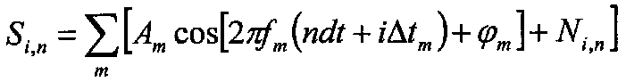
도 2는 인접하는 수신용 안테나가 축(30)을 따라 정렬되고 고정된 거리(d)만큼 분리되어 있는 안테나 어레이(21)의 구성을 개략적으로 나타내고 있다. 어레이(21)로부터 감시 공간 내에서 검출된 신호원, 예컨대 송신기(22) 내지 (25) 등까지의 거리는, 어레이 내의 각 안테나로부터 송신기까지의 각각의 광선(R)이 실질적으로 평행한 어레이(21)의 길이에 비해서, 충분히 크며, 따라서, 축(30)과 함께 동일한 방위각(θ)을 결정한다. 제n번째 샘플 중 수신용 안테나 어레이(21)의 제i번째 수신기(Ai)에 수집된 신호는 다음 수학식 1과 같이 모델화될 수 있다:2 schematically shows the configuration of the
![]()
![]()
식 중, t = 시간, Wherein t = time,
A = 진폭,A = amplitude,
f = EM 방사선의 주파수,f = frequency of EM radiation,
dt = 샘플들 간의 신호의 시간 지연,dt = time delay of signal between samples,
Δt = 어레이 내의 인접한 안테나로부터의 신호의 시간 지연,DELTA t = time delay of signals from adjacent antennas in the array,
Ni,n = n번째 샘플 중 i번째 안테나에서의 잡음.N i, n = Noise at the ith antenna of the nth sample.
신호(Si,n)들은 각 신호(Si,n)가 송신기로부터 안테나(Ai)로 각각의 광선(32)을 따라 주행하는 거리가 각 신호마다 다르다는 사실에 기인한 각각의 시간 지연(iΔt)을 가진다. 도 2에 있어서, 광선(Ri)을 따라 신호(Si,n)가 주행하는 거리는 광선(R0)을 따라 신호(S0)가 주행하는 거리를 이하의 수학식 2로 부여되는 양(Δt)만큼 초과하는 것을 알 수 있다:The signals S i, n are each time delay due to the fact that the distance that each signal S i, n travels along the respective ray 32 from the transmitter to the antenna A i is different for each signal i? t). 2, the distance traveled by the signal S i, n along the ray R i is defined as the distance traveled by the signal S 0 along the ray R 0 to the amount given by Equation 2 below: DELTA t): < RTI ID = 0.0 >

식 중, c는 신호들의 전파 속도이고, d는 안테나들 사이의 고정 거리이다.Where c is the propagation velocity of the signals and d is the fixed distance between the antennas.
도 1을 재차 참조하면, 각 안테나(A)는 그의 각각의 수신기 채널(RC)에 제공되는 그의 각각의 신호(S)를 수신한다. 신호(Si,n)는 공지의 샘플링 속도로 수신기(RC)에 의해 샘플링되어, 샘플링된 값의 2차원 어레이를 얻는다:Referring again to Figure 1, each antenna A receives its respective signal S provided on its respective receiver channel RC. The signal S i, n is sampled by the receiver RC at a known sampling rate to obtain a two-dimensional array of sampled values:
![]()
![]()
식 중, n은 샘플링 속도를 이용해서 얻어진 샘플 수이다. n의 고정된 값에 대해서, 수열(Si,n)은 1/Δt와 동일한 샘플링 속도에서 각각의 신호원(22) 내지 (25)에 의해 방사된 신호의 샘플링이다.Where n is the number of samples obtained using the sampling rate. For a fixed value of n, the sequence (S i, n ) is the sampling of the signal emitted by each signal source (22) - (25) at a sampling rate equal to 1 /? t.
m개의 동시 신호에 대해서, 이것은 다음 수학식 4를 부여한다:For m simultaneous signals, this gives: < RTI ID = 0.0 >
일 실시형태에 있어서, (Si,n)의 값은 Si,n>0일 때에는 Si,n=1을 설정하고, Si,n≤0일 때에는 Si,n=-1을 설정해서 이진화되어 있다. 신호를 이진화화는 것은 하드웨어 및 소프트웨어를 단순화하는 데, 그 이유는, 지금까지 제안된 접근법에 비해서 본 발명의 특별한 이점이 본 발명이 개별적으로 잡음과 식별할 수 없는 약한 신호를 검출하는 것을 가능하게 하기 때문이다. 잡음과 식별할 수 없는 이러한 작은 규모의 신호에 멀티비트값을 할당하는 시도에서의 어떠한 혜택도 중요하지 않고, 이것은 일반적으로 신호를 이진화함으로써 얻을 수 있는 처리 및 하드웨어에서 보다 크게 단순하게 오프셋된다. 한편, 동시에 멀티 신호의 동적 영역이 요구되는 경우, 멀티비트 처리는 처리 복잡성을 저감시키도록 보다 적은 수의 안테나를 이용하는 것이 바람직할 수 있다.In one embodiment, the value of (S i, n) is S i, n> set S i, n = 1 and one 0 if, S i, n set S i, n = -1 when the ≤0 And is binarized. The binarization of the signal simplifies the hardware and software because a particular advantage of the present invention over the approaches heretofore proposed is that it allows the present invention to individually detect weak signals that can not be distinguished from noise . No benefit in attempting to assign multi-bit values to these small signals that are indistinguishable from noise is unimportant, and this is generally much simpler offset in the processing and hardware that can be achieved by binarizing the signal. On the other hand, when a dynamic range of a multi-signal is required at the same time, it is preferable to use a smaller number of antennas so as to reduce processing complexity in multi-bit processing.
2차원 어레이(Si,n)는 방위 결정 처리 스테이지(11)에 투입된다. 방위 결정 처리는 상기 어레이(Si,n)의 2차원 퓨리에 변환을 산출하는 단계를 포함한다. 여기서 "주파수-방위 플롯"(frequency-azimuth plot)이라고도 칭해지는 퓨리에 변환은 2차원 어레이(Fjk)이다. j는 이하의 수학식 5를 충족시키는 빈 넘버이다:The two-dimensional array S i, n is put into the orientation

식 중, f는 EM 방사선의 가능하게는 미지의 주파수이고, N은 이 차원의 빈의 개수(the number of bins)이고, k는 이하의 수학식 6을 충족시키는 빈 넘버이다:Where f is the possibly unknown frequency of the EM radiation, N is the number of bins of this dimension, and k is a bin number that meets the following equation:

식 중, N'는 이 차원의 빈의 개수이다.Where N 'is the number of beans in this dimension.
수학식 2를 수학식 6에 대입하면 이하의 수학식 7 또는 등가적으로는 수학식 8이 얻어진다:Substituting Equation (2) into Equation (6) yields Equation (7) or Equation (8) below:


어레이(Fjk)는 감시 공간에 있는 신호원(22) 내지 (25)으로부터 방사된 신호를 동정하여 이들 신호를 클러터로부터 분리하기 위하여, 1개 이상의 소정의 기준 을 충족시키는 피크에 대해서 방위 결정 처리 스테이지(11)에서 주사된다. 소정의 기준은, 예를 들어, 소정의 역치 이상의 피크 진폭을 포함할 수 있다. 각 동정된 신호원의 주파수(f)는 수학식 5를 이용해서 상기 피크의 빈 넘버(j)로부터 결정된다. 이것은 빈의 개수(N)에 의해 정확도가 결정되는 (f)의 값을 생성한다. 주파수 결정의 정확도는 퓨리에 분석의 기술분야에서 공지된 바와 같이 위상 데이터를 이용해서 향상될 수도 있다. 주파수 불명료(ambiguity)의 문제에 대처하기 위하여, 본 발명의 방법은 상이한 "클록"(clock) 값을 이용하고/하거나 RF 필터를 이용해서 적어도 2회 수행될 수 있다. 일단 주파수를 알면, 신호원의 방위각(θ)은 수학식 7을 이용해서 피크의 빈 넘버(k)로부터 결정된다. 상기 처리 스테이지(11)의 출력(26)은 각 검출된 신호에 대한 방위각과 임의선택적으로 각 검출된 신호의 주파수를 포함한다.The array F jk is used to identify signals radiated from the signal sources 22 to 25 in the monitoring space and to determine the orientation for the peaks meeting one or more predetermined criteria And is scanned in the
도 3은 본 발명의 방법에 의해 실제 데이터에 대해 얻어진 2차원 주파수-방위 플롯(35)을 나타낸다. 이 데이터는 128개의 수신기의 선형 어레이를 이용해서 수집되었다. 상기 플롯은 512개의 신호 샘플을 이용해서 얻어졌다. 플롯(35)은 감시 영역 내에 있는 상이한 2개의 신호원에 대응하는 2개의 피크(36), (37)를 지닌다. 피크(36)는 (f1)의 주파수와 30°의 방위각을 지닌 신호를 나타낸다. 이 신호는 -18 db의 신호 대 잡음으로 검출되었다. 피크(37)는 (f2)의 주파수와 50°의 방위각을 지닌 신호를 나타낸다. 이 신호는 -20 db의 신호 대 잡음으로 검출되었다. 상기 어레이에 있어서의 검출기의 개수를 증가시키는 것은 감도를 증강시킨 다.3 shows a two-dimensional frequency-orientation plot 35 obtained for the actual data by the method of the present invention. This data was collected using a linear array of 128 receivers. The plot was obtained using 512 signal samples. Plot 35 has two peaks 36, 37 corresponding to two different signal sources in the monitoring area. Peak 36 represents a signal having a frequency of (f 1 ) and an azimuth angle of 30 °. This signal was detected with a signal-to-noise of -18 dB. Peak 37 represents a signal with a frequency of (f 2 ) and an azimuth angle of 50 °. This signal was detected with a signal to noise of -20 dB. Increasing the number of detectors in the array increases sensitivity.
도 4는 도 1 내지 도 3을 특히 참조하여 전술한 바와 같은 신호원의 주파수 및 방위각을 결정하기 위한 본 발명의 일 실시형태에 따라 수행되는 주된 동작을 요약하여 나타낸 순서도이다.4 is a flow chart summarizing the main operations performed in accordance with an embodiment of the present invention for determining the frequency and azimuth angle of a signal source as described above specifically with reference to Figs.
단, 본 발명의 시스템은 수신용 안테나의 하나 이상의 어레이를 이용해서 구현될 수 있다. 예를 들어, 본 발명은 수신용 안테나의 상호 수직인 2개의 어레이를 이용해서 구현될 수 있다. 2차원 퓨리에 변환(Fjk)의 추가의 퓨리에 변환은, 이어서, 각 동정된 이미터에 대해서, 신호원의 위치 벡터를 함께 규정하는 2개의 독립적인 각도(방위 및 앙각(elevation))를 생성한다.However, the system of the present invention may be implemented using one or more arrays of receiving antennas. For example, the present invention can be implemented using two arrays that are mutually perpendicular to the receiving antennas. The additional Fourier transform of the two-dimensional Fourier transform F jk then produces two independent angles (azimuth and elevation) that together define the source vector of the source for each identified emitter .
또, 신호원은 활성 송신기일 필요는 없지만, 예컨대, 반사된 신호일 수도 있음을 알 수 있을 것이다.It will also be appreciated that the signal source need not be an active transmitter, but may, for example, be a reflected signal.
또한, 본 발명에 따른 검출기 어레이에 의해 검출된 신호는 2차원 공간에서 공간적으로 분리되므로, 2차원 공간 내에서 떨어져서 이간되어 있지만 동일한 주파수를 지니는 신호가 이산적으로 검출될 것이다.Further, the signals detected by the detector array according to the present invention are spatially separated in the two-dimensional space, so that signals separated at a distance but spaced apart in the two-dimensional space but having the same frequency will be discretely detected.
또, 일단 송신기의 주파수와 방향이 FFT를 이용해서 결정되면, 이산(Discrete) 퓨리에 변환을 이용해서 상기 검출된 송신기를 트래킹하므로 처리 시간이 절약될 수 있다.In addition, once the frequency and direction of the transmitter are determined using the FFT, processing time can be saved because the detected transmitter is tracked using discrete Fourier transform.
또한, 본 발명에 의한 시스템은 적절하게 프로그래밍된 컴퓨터일 수도 있음을 알 수 있을 것이다. 마찬가지로, 본 발명은 본 발명의 방법을 수행하기 위하여 컴퓨터에 의해 판독가능한 컴퓨터 프로그램을 상정하고 있다. 본 발명은 또한 본 발명의 방법을 수행하기 위하여 기계에 의해 수행가능한 지시를 행하는 프로그램을 명백히 구현하는 기계 판독가능한 메모리도 상정하고 있다.It will also be appreciated that the system according to the present invention may be a suitably programmed computer. Likewise, the present invention contemplates a computer program readable by a computer for carrying out the method of the present invention. The present invention also contemplates a machine-readable memory that explicitly implements a program that performs instructions that are machine-executable to perform the method of the present invention.
Claims (31)


Applications Claiming Priority (3)
| Application Number | Priority Date | Filing Date | Title |
|---|---|---|---|
| IL179186 | 2006-11-12 | ||
| IL179186A IL179186A0 (en) | 2006-11-12 | 2006-11-12 | Method and system for detecting signal soures in a surveillance space |
| PCT/IL2007/001329 WO2008059476A1 (en) | 2006-11-12 | 2007-10-31 | Method and system for detecting signal sources in a surveillance space |
Publications (2)
| Publication Number | Publication Date |
|---|---|
| KR20090104806A KR20090104806A (en) | 2009-10-06 |
| KR101435168B1 true KR101435168B1 (en) | 2014-09-01 |
Family
ID=39046781
Family Applications (1)
| Application Number | Title | Priority Date | Filing Date |
|---|---|---|---|
| KR1020097011925A KR101435168B1 (en) | 2006-11-12 | 2007-10-31 | Method and system for detecting signal sources in a surveillance space |
Country Status (6)
| Country | Link |
|---|---|
| US (2) | US8022874B2 (en) |
| EP (2) | EP2087368B1 (en) |
| KR (1) | KR101435168B1 (en) |
| AU (1) | AU2007320792B2 (en) |
| IL (2) | IL179186A0 (en) |
| WO (1) | WO2008059476A1 (en) |
Cited By (1)
| Publication number | Priority date | Publication date | Assignee | Title |
|---|---|---|---|---|
| KR20180130900A (en) * | 2017-05-30 | 2018-12-10 | 한국전자통신연구원 | Narrow-band radar device and operating method thereof |
Families Citing this family (15)
| Publication number | Priority date | Publication date | Assignee | Title |
|---|---|---|---|---|
| US8081214B2 (en) * | 2004-10-12 | 2011-12-20 | Enforcement Video, Llc | Method of and system for mobile surveillance and event recording |
| US8982944B2 (en) * | 2005-10-12 | 2015-03-17 | Enforcement Video, Llc | Method and system for categorized event recording of images in multiple resolution levels |
| US8599368B1 (en) | 2008-01-29 | 2013-12-03 | Enforcement Video, Llc | Laser-based speed determination device for use in a moving vehicle |
| CA2714362A1 (en) * | 2008-01-29 | 2009-08-06 | Enforcement Video, Llc | Omnidirectional camera for use in police car event recording |
| US9860536B2 (en) * | 2008-02-15 | 2018-01-02 | Enforcement Video, Llc | System and method for high-resolution storage of images |
| KR101562904B1 (en) * | 2009-06-12 | 2015-10-23 | 삼성전자주식회사 | Direction of Arrival Estimation Apparatus and Method therof |
| US8736680B1 (en) | 2010-05-18 | 2014-05-27 | Enforcement Video, Llc | Method and system for split-screen video display |
| IL221162A (en) | 2012-07-29 | 2017-06-29 | Elta Systems Ltd | Transponder device |
| DE102013111633B4 (en) * | 2012-11-06 | 2021-04-01 | Electronics And Telecommunications Research Institute | Method and device for radio location |
| IL223619A (en) | 2012-12-13 | 2017-08-31 | Elta Systems Ltd | System and method for coherent processing of signals of a plurality of phased arrays |
| US9706298B2 (en) | 2013-01-08 | 2017-07-11 | Stmicroelectronics S.R.L. | Method and apparatus for localization of an acoustic source and acoustic beamforming |
| US9759807B2 (en) * | 2013-10-25 | 2017-09-12 | Texas Instruments Incorporated | Techniques for angle resolution in radar |
| US20150285904A1 (en) * | 2014-04-04 | 2015-10-08 | Texas Instruments Incorporated | Antenna configuration for parking assist radar |
| US10341605B1 (en) | 2016-04-07 | 2019-07-02 | WatchGuard, Inc. | Systems and methods for multiple-resolution storage of media streams |
| CN112649791B (en) * | 2020-12-24 | 2022-08-05 | 北京海兰信数据科技股份有限公司 | Radar echo processing method and device |
Citations (4)
| Publication number | Priority date | Publication date | Assignee | Title |
|---|---|---|---|---|
| US5444451A (en) | 1992-06-29 | 1995-08-22 | Southwest Research Institute | Passive means for single site radio location |
| US5585803A (en) | 1994-08-29 | 1996-12-17 | Atr Optical And Radio Communications Research Labs | Apparatus and method for controlling array antenna comprising a plurality of antenna elements with improved incoming beam tracking |
| US6278406B1 (en) | 1998-03-24 | 2001-08-21 | Nec Corporation | Direction finder and device for processing measurement results for the same |
| US6446025B1 (en) | 1998-03-26 | 2002-09-03 | Nec Corporation | Multiple propagation wave parameter measuring method and apparatus and machine-readable recording medium recording multiple propagation wave parameter measuring program |
Family Cites Families (9)
| Publication number | Priority date | Publication date | Assignee | Title |
|---|---|---|---|---|
| US4649392A (en) * | 1983-01-24 | 1987-03-10 | Sanders Associates, Inc. | Two dimensional transform utilizing ultrasonic dispersive delay line |
| US4646099A (en) * | 1983-09-28 | 1987-02-24 | Sanders Associates, Inc. | Three-dimensional fourier-transform device |
| US4802149A (en) * | 1986-12-18 | 1989-01-31 | Harris Corp. | Acousto-optic two-dimensional coherent optical modulator |
| US5327144A (en) | 1993-05-07 | 1994-07-05 | Associated Rt, Inc. | Cellular telephone location system |
| DE4425661A1 (en) | 1994-07-20 | 1996-01-25 | Daimler Benz Aerospace Ag | Large base interferometer direction finder system |
| WO2005116681A1 (en) | 2004-05-28 | 2005-12-08 | Telefonaktiebolaget Lm Ericsson (Publ) | A method for processing signals in a direction-finding system |
| WO2006067857A1 (en) * | 2004-12-24 | 2006-06-29 | Fujitsu Limited | Arrival direction estimating device and program |
| US7427954B2 (en) * | 2005-04-07 | 2008-09-23 | Bae Systems Information And Electronic Systems Integration Inc. | Method and apparatus for direction finding |
| US7345618B1 (en) * | 2005-04-14 | 2008-03-18 | L-3 Communications Cyterra Corporation | Moving-entity detection |
-
2006
- 2006-11-12 IL IL179186A patent/IL179186A0/en unknown
-
2007
- 2007-10-31 KR KR1020097011925A patent/KR101435168B1/en active IP Right Grant
- 2007-10-31 AU AU2007320792A patent/AU2007320792B2/en not_active Ceased
- 2007-10-31 US US12/514,523 patent/US8022874B2/en active Active
- 2007-10-31 EP EP07827303.4A patent/EP2087368B1/en active Active
- 2007-10-31 WO PCT/IL2007/001329 patent/WO2008059476A1/en active Application Filing
- 2007-10-31 EP EP14163068.1A patent/EP2752679A3/en not_active Withdrawn
-
2009
- 2009-05-12 IL IL198702A patent/IL198702A/en active IP Right Grant
-
2011
- 2011-08-18 US US13/212,652 patent/US8274432B2/en active Active
Patent Citations (4)
| Publication number | Priority date | Publication date | Assignee | Title |
|---|---|---|---|---|
| US5444451A (en) | 1992-06-29 | 1995-08-22 | Southwest Research Institute | Passive means for single site radio location |
| US5585803A (en) | 1994-08-29 | 1996-12-17 | Atr Optical And Radio Communications Research Labs | Apparatus and method for controlling array antenna comprising a plurality of antenna elements with improved incoming beam tracking |
| US6278406B1 (en) | 1998-03-24 | 2001-08-21 | Nec Corporation | Direction finder and device for processing measurement results for the same |
| US6446025B1 (en) | 1998-03-26 | 2002-09-03 | Nec Corporation | Multiple propagation wave parameter measuring method and apparatus and machine-readable recording medium recording multiple propagation wave parameter measuring program |
Cited By (2)
| Publication number | Priority date | Publication date | Assignee | Title |
|---|---|---|---|---|
| KR20180130900A (en) * | 2017-05-30 | 2018-12-10 | 한국전자통신연구원 | Narrow-band radar device and operating method thereof |
| KR102424252B1 (en) | 2017-05-30 | 2022-07-25 | 한국전자통신연구원 | Narrow-band radar device and operating method thereof |
Also Published As
| Publication number | Publication date |
|---|---|
| KR20090104806A (en) | 2009-10-06 |
| US20100231455A1 (en) | 2010-09-16 |
| IL179186A0 (en) | 2008-01-20 |
| IL198702A (en) | 2014-09-30 |
| US20110304509A1 (en) | 2011-12-15 |
| WO2008059476A1 (en) | 2008-05-22 |
| US8022874B2 (en) | 2011-09-20 |
| AU2007320792B2 (en) | 2012-06-07 |
| EP2752679A3 (en) | 2014-08-27 |
| EP2087368A1 (en) | 2009-08-12 |
| EP2087368B1 (en) | 2014-06-11 |
| AU2007320792A1 (en) | 2008-05-22 |
| EP2752679A2 (en) | 2014-07-09 |
| US8274432B2 (en) | 2012-09-25 |
| IL198702A0 (en) | 2010-02-17 |
Similar Documents
| Publication | Publication Date | Title |
|---|---|---|
| KR101435168B1 (en) | Method and system for detecting signal sources in a surveillance space | |
| EP0446678B1 (en) | Polystatic correlating radar | |
| EP1972962A2 (en) | Transmitter independent techniques to extend the performance of passive coherent location | |
| US20180306902A1 (en) | Mimo radar system and calibration method thereof | |
| US20200408878A1 (en) | A radar transceiver with reduced false alarm rate | |
| EP2182375A1 (en) | A combined direction finder and radar system, method and computer program product | |
| US10656248B2 (en) | Radar post processing for sidelobe suppression | |
| KR100824552B1 (en) | System and method for detection and feature extraction in passive coherent location applications | |
| CA2598291A1 (en) | Method of detection in bistatic mode using non-cooperative passive radiotransmissions | |
| AU2002314766A1 (en) | System and method for detection and feature extraction in passive coherent location applications | |
| CN112782685B (en) | Multi-sound-source positioning and sound reconstruction method and system based on MIMO radar | |
| Kłos et al. | On the possibility of using LOFAR radio telescope for passive radiolocation | |
| RU2315332C1 (en) | Radiolocation station | |
| CN108594200B (en) | Fully coherent target detection method of passive MIMO radar | |
| KR20200131526A (en) | Position Detecting System and Method of Ultra Wide Band Using the Optimized Detection Threshold at Objects Size and Motion Strenth | |
| Hu et al. | Weak target detection method of passive bistatic radar based on probability histogram | |
| RU2471200C1 (en) | Method for passive detection and spatial localisation of mobile objects | |
| RU2510708C1 (en) | Radio-frequency radiation source direction-finding method | |
| RU2319168C1 (en) | Device for compensating signals received through side directional lobes | |
| RU2431864C1 (en) | Detection and direction finding method of air objects | |
| US6473029B1 (en) | System for recognizing signal of interest within noise | |
| Jun et al. | Passive coherent detection via exploiting illuminator of opportunity | |
| Van Cao | Sequential detection for passive radar part 1: The AC DF-map detector | |
| Vertogradov et al. | Moving Objects Parameters Estimation Based on Direction Finding of Broadcasting HF Radio Stations Scattered Radiation | |
| Żywek et al. | Experimental Analysis of the Environmental Noise in Passive Radar Based on FM Radio |
Legal Events
| Date | Code | Title | Description |
|---|---|---|---|
| A201 | Request for examination | ||
| E902 | Notification of reason for refusal | ||
| E701 | Decision to grant or registration of patent right | ||
| FPAY | Annual fee payment |
Payment date: 20170719 Year of fee payment: 4 |
|
| FPAY | Annual fee payment |
Payment date: 20180809 Year of fee payment: 5 |
|
| FPAY | Annual fee payment |
Payment date: 20190816 Year of fee payment: 6 |