KR101562904B1 - Direction of Arrival Estimation Apparatus and Method therof - Google Patents
Direction of Arrival Estimation Apparatus and Method therof Download PDFInfo
- Publication number
- KR101562904B1 KR101562904B1 KR1020090052563A KR20090052563A KR101562904B1 KR 101562904 B1 KR101562904 B1 KR 101562904B1 KR 1020090052563 A KR1020090052563 A KR 1020090052563A KR 20090052563 A KR20090052563 A KR 20090052563A KR 101562904 B1 KR101562904 B1 KR 101562904B1
- Authority
- KR
- South Korea
- Prior art keywords
- signal
- distance
- arrival angle
- following equation
- fft
- Prior art date
Links
Images
Classifications
-
- G—PHYSICS
- G01—MEASURING; TESTING
- G01S—RADIO DIRECTION-FINDING; RADIO NAVIGATION; DETERMINING DISTANCE OR VELOCITY BY USE OF RADIO WAVES; LOCATING OR PRESENCE-DETECTING BY USE OF THE REFLECTION OR RERADIATION OF RADIO WAVES; ANALOGOUS ARRANGEMENTS USING OTHER WAVES
- G01S3/00—Direction-finders for determining the direction from which infrasonic, sonic, ultrasonic, or electromagnetic waves, or particle emission, not having a directional significance, are being received
- G01S3/02—Direction-finders for determining the direction from which infrasonic, sonic, ultrasonic, or electromagnetic waves, or particle emission, not having a directional significance, are being received using radio waves
- G01S3/74—Multi-channel systems specially adapted for direction-finding, i.e. having a single antenna system capable of giving simultaneous indications of the directions of different signals
-
- G—PHYSICS
- G01—MEASURING; TESTING
- G01S—RADIO DIRECTION-FINDING; RADIO NAVIGATION; DETERMINING DISTANCE OR VELOCITY BY USE OF RADIO WAVES; LOCATING OR PRESENCE-DETECTING BY USE OF THE REFLECTION OR RERADIATION OF RADIO WAVES; ANALOGOUS ARRANGEMENTS USING OTHER WAVES
- G01S3/00—Direction-finders for determining the direction from which infrasonic, sonic, ultrasonic, or electromagnetic waves, or particle emission, not having a directional significance, are being received
- G01S3/80—Direction-finders for determining the direction from which infrasonic, sonic, ultrasonic, or electromagnetic waves, or particle emission, not having a directional significance, are being received using ultrasonic, sonic or infrasonic waves
- G01S3/802—Systems for determining direction or deviation from predetermined direction
- G01S3/808—Systems for determining direction or deviation from predetermined direction using transducers spaced apart and measuring phase or time difference between signals therefrom, i.e. path-difference systems
-
- H—ELECTRICITY
- H04—ELECTRIC COMMUNICATION TECHNIQUE
- H04B—TRANSMISSION
- H04B7/00—Radio transmission systems, i.e. using radiation field
- H04B7/02—Diversity systems; Multi-antenna system, i.e. transmission or reception using multiple antennas
- H04B7/04—Diversity systems; Multi-antenna system, i.e. transmission or reception using multiple antennas using two or more spaced independent antennas
- H04B7/08—Diversity systems; Multi-antenna system, i.e. transmission or reception using multiple antennas using two or more spaced independent antennas at the receiving station
- H04B7/0837—Diversity systems; Multi-antenna system, i.e. transmission or reception using multiple antennas using two or more spaced independent antennas at the receiving station using pre-detection combining
- H04B7/0842—Weighted combining
- H04B7/086—Weighted combining using weights depending on external parameters, e.g. direction of arrival [DOA], predetermined weights or beamforming
Abstract
광대역 전파 신호의 도래각을 도출하는 도래각 측정 장치 및 측정 방법이 제공된다. 도래각 측정장치는 수학식(d≤Mc/2fs, 여기서 c는 음속, M은 광대력 주파수 개수 즉 광대역 신호의 고속 푸리에 변환(FFT) 포인트 개수, fs는 샘플링 주파수)을 만족하고 상한값에 근접하는 거리(d)로 이격되어 광대역 신호를 수신하는 제1 및 제2신호 수신부 및, 상기 제1 및 제2신호 수신부로부터 전달되는 상기 광대역 신호를 고속 푸리에 변환하여 도출되는 정규 주파수와 상기 거리를 이용하여 도래각을 산출하는 도래각 계산부를 포함한다. There is provided an arrival angle measuring apparatus and a measuring method for deriving an arrival angle of a wideband radio wave signal. The arrival angle measuring device satisfies the equation (d? Mc / 2fs, where c is the sonic velocity, M is the number of the large power frequency, i.e., the number of fast Fourier transform (FFT) points of the wideband signal, fs is the sampling frequency) A first and a second signal receiving unit spaced apart from each other by a distance d to receive a wideband signal and a normal frequency derived by fast Fourier transforming the wideband signal transmitted from the first and second signal receiving units, And an arrival angle calculation unit for calculating an arrival angle.
도래각, DOA, 광대역, 전파, FFT DOA, Wideband, Propagation, FFT
Description
본 발명의 일부 실시예들은 광대역 전파 신호를 수신하는 도래각 측정 장치 및 방법에 관한 것이다. 보다 상세하게는, FFT를 이용하여 광대역(wideband) 신호의 도래각을 도출하는 도래각 측정 장치 및 방법에 연관된다.Some embodiments of the present invention are directed to an apparatus and method for measuring incoming angles that receive a wideband propagation signal. More particularly, the present invention relates to an apparatus and method for measuring the angle of arrival of a wideband signal using an FFT.
최근 들어 비즈니스 미팅 관련 전자 장치와 가정에서의 엔터테인먼트나 비디오 게임 등의 소형 전자장치가 일상 생활에서 점점 더 인기를 얻고 있다. 이에 따라 대화자 또는 물체를 자동 트래킹하기 위해 도래각(DOA: Direction of Arrival) 측정 기술이 휴먼 컴퓨터 인터페이스(HCI: Human Computer Interface)에 접목되어 HCI 기술을 더욱 인간 친화적이고 실용적으로 만들고 있다. 따라서, 도래각(DOA) 측정 방법은 레이더, 센서 네트워크 및 대화 소통 시스템에서 광범위하게 연구되고 있다. In recent years, electronic devices for business meetings and small electronic devices such as home entertainment and video games have become increasingly popular in everyday life. Accordingly, Direction of Arrival (DOA) measurement technology is applied to human computer interface (HCI) to automatically track a speaker or object, making HCI technology more human-friendly and practical. Therefore, the DOA measurement method has been extensively studied in radar, sensor networks, and communication systems.
일반적으로 사용되고 있는 도래각 측정 방법에는 다중 신호 분류(MUSIC: Multiple Signal Classification) 방법이 있다. MUSIC은 협대역(narrowband) 신호 의 도래각 검출에 적용하기 위해 슈미트(Schmidt)가 제안한 기술이다. 광대역 신호 의 도래각을 구하기 위해, 본래 협대역 전파 신호에 사용되던 MUSIC 기술을 수정 개선하는 연구가 진행되어 왔는데, 광대역 신호를 다중 주파수 빈으로 분해하여 협대역 알고리즘을 적용함으로써 도래각을 구하고 대상의 방향을 구하는 방식을 사용하였다. There are multiple signal classification (MUSIC) methods for the arrival angle measurement method generally used. MUSIC is a technique proposed by Schmidt to apply to detection of the arrival angle of a narrowband signal. In order to obtain the angle of arrival of the wideband signal, research has been carried out to improve the MUSIC technique originally used for the narrowband radio signal. The narrow angle band algorithm is applied to the wideband signal, Direction was obtained.
센서 어레이에 의한 도래각 추정 방법에서는 센서 간 간격을 너무 크게 하면 존재하지 않는 소스원이 마치 존재하는 것처럼 보이게 되는데, 이 현상을 공간상의 앨리아싱(spatial aliasing)이라고 한다. 그러므로 이러한 앨리아싱을 방지하기 위해서는 센서 간격을 수신되는 신호의 반파장보다 최소한 작게 해야 한다. 그러나 센서 간격이 작을 경우 원거리에서 수신되는 신호에 대해서는 정확한 도래각을 추정할 수 없으므로 이의 대안으로 보다 많은 수의 센서가 필요하게 된다.In the method of estimating the arrival angle by the sensor array, if the interval between the sensors is made too large, the source circle that does not exist appears to exist as if it exists. This phenomenon is called spatial aliasing. Therefore, to prevent such aliasing, the sensor interval should be at least smaller than half the wavelength of the received signal. However, if the sensor interval is small, it is not possible to estimate the correct angle of arrival for a signal received from a long distance. Therefore, a larger number of sensors are required as an alternative thereto.
여기에서, 도래각 분해능은 센서 어레이 개구(aperture)의 최대 길이에 비례한다. 상기 두 개의 조건은 MUSIC 적용시 보다 많은 수의 센서가 사용되어야 한다는 것을 나타낸다. 지금까지 광대역 전파 신호의 도래각에 관련된 대부분의 연구가 종래 MUSIC 과 같은 고 분해능 방법에 기초하므로, 센서 갯수가 많아지고 따라서 계산은 더욱 더 복잡해지는 양상을 나타내고 있다. Here, the incoming angular resolution is proportional to the maximum length of the sensor array aperture. These two conditions indicate that a greater number of sensors should be used in MUSIC applications. So far, most researches related to the angle of arrival of broadband signal are based on high resolution method like conventional MUSIC, so that the number of sensors is increased and the calculation becomes more complicated.
따라서, 최소한의 적은 수의 센서만을 이용하여 보다 간편하게, 도래각을 측정할 수 있는 방법 및 장치가 제안될 필요가 있다.Therefore, there is a need to propose a method and an apparatus that can more easily measure the arrival angle using only a small number of sensors.
본 발명의 일부 실시예는, 수신된 신호의 일부 협대역 정보를 이용하기 보다 광대역의 정보를 이용함으로써 보다 적은 수의 센서, 즉 신호 수신부만으로 높은 주파수 분해능을 가지는 도래각 측정 장치 및 방법을 제공하기 위한 것이다.Some embodiments of the present invention provide an arrival angle measuring apparatus and method having a high frequency resolution only by using a smaller number of sensors, that is, a signal receiving unit, by using information of a wide band rather than using some narrow band information of a received signal .
또한 본 발명의 일부 실시예는, 신호의 반파장의 제약을 벗어나도록 신호 수신부간 거리를 설정함으로써 도래각 측정의 품질을 높이는 것이다.Some embodiments of the present invention also improve the quality of incoming measurements by setting the distance between signal receivers to exceed the limit of the half-wave of the signal.
또한 본 발명의 일부 실시예는, 간단한 FFT 연산을 통하여 두 개의 신호 수신부에서 수신되는 전파 신호의 도래각을 측정하는 것이다.In some embodiments of the present invention, the arrival angle of a radio wave signal received by two signal receiving units is measured through a simple FFT operation.
본 발명의 일 실시예에 따르면, 수학식(d≤Mc/2fs, 여기서 c는 음속, M은 광대력 주파수 개수 즉 광대역 신호의 고속 푸리에 변환(FFT) 포인트 개수, fs는 샘플링 주파수)을 만족하고 상한값에 근접하는 거리(d)로 이격되어 광대역 신호를 수신하는 제1 및 제2신호 수신부 및, 상기 제1 및 제2신호 수신부로부터 전달되는 상기 광대역 신호를 고속 푸리에 변환하여 도출되는 정규 주파수와 상기 거리를 이용하여 도래각을 산출하는 도래각 계산부;를 포함하는 도래각 측정장치가 제공된다.According to one embodiment of the present invention, the following equation is satisfied (d? Mc / 2fs, where c is the sonic velocity, M is the number of the large power frequency, i.e. the number of FFT points of the wideband signal and fs is the sampling frequency) A first signal receiver for receiving a wideband signal at a distance d closer to the upper limit value and a second frequency detector for receiving the wideband signal from the first and second signal receivers, And an arrival angle calculating section for calculating an arrival angle using the distance.
본 발명의 다른 일 실시예에 따르면, 제1 및 제2신호 수신부를 다음 수학식 (d≤Mc/2fs)을 만족하고 상한값에 근접하는 거리(d)로 이격시켜 설치하는 단계; 상기 제1 및 제2신호 수신부에 수신되는 광대역 신호에 대해 각각 고속 푸리에 변환을 수행하여 정규 주파수를 구하는 단계; 및 상기 정규 주파수와 상기 거리를 이용하여 상기 광대역 신호의 도래각을 산출하는 단계;를 포함하는 도래각 측정방법을 제공한다.
또한 본 발명의 다른 일 실시예에 따르면, 상기 도래각 측정방법을 수행하기 위한 명령어를 수록한 컴퓨터 판독 가능 기록 매체를 제공한다.According to another embodiment of the present invention, there is provided a method of controlling a communication system, the method comprising: installing first and second signal reception units at distances d satisfying the following equation (d? Mc / 2fs) and approaching an upper limit; Performing a fast Fourier transform on the wideband signal received by the first and second signal receivers to obtain a normal frequency; And calculating an arrival angle of the wideband signal using the normal frequency and the distance.
According to another embodiment of the present invention, there is provided a computer-readable recording medium storing a command for performing the method of measuring the arrival angle.
본 발명의 일부 실시예에 따르면, 수신된 신호의 광대역 정보를 활용함으로써 단지 두 개의 신호 수신부만으로도 높은 주파수 분행능을 가지는 도래각을 측정할 수 있다.According to some embodiments of the present invention, by using the wideband information of the received signal, it is possible to measure the angle of incidence having high frequency division capability with only two signal receivers.
또한 본 발명의 일부 실시예에 따르면, 신호 수신부 간 거리가 주파수 분해능과 관련되어 설정되므로 거리의 제한이 완화되어 장치의 구현이 용이하다.Further, according to some embodiments of the present invention, since the distance between the signal receivers is set in relation to the frequency resolution, the limitation of the distance is relaxed and the device is easy to implement.
이 외에도 본 발명의 일부 실시예에 따르면, 간단한 FFT 연산을 통해 도래각을 산출하므로 계산이 복잡하지 않으며, 도래각 측정의 품질을 향상시킨다.In addition, according to some embodiments of the present invention, calculation of the angle of incidence is performed through a simple FFT calculation, so that the calculation is not complicated and the quality of the arrival angle measurement is improved.
이하에서, 본 발명의 일부 실시예를, 첨부된 도면을 참조하여 상세하게 설명한다. 그러나, 본 발명이 실시예들에 의해 제한되거나 한정되는 것은 아니다.Hereinafter, some embodiments of the present invention will be described in detail with reference to the accompanying drawings. However, the present invention is not limited to or limited by the embodiments.
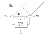
도 1은 본 발명의 일 실시예에 따른 도래각 측정 장치(100)를 도시한다.1 shows an apparatus for measuring an angle of
본 발명의 일 실시예에 따르면, 도래각 측정 장치(100)은 제1 및 제2 신호 수신부(110, 112)와 도래각 계산부(114)를 포함한다. 제1 및 제2 신호 수신부(110, 112)는 외부 대상으로부터 송신되는 전파를 수신하는 센서이다. 제1 및 제2 신호 수신부(110, 112)는 도래각 측정을 위해 설정된 거리로 이격된다. According to an embodiment of the present invention, the arrival
전파 신호는 제1 및 제2 신호 수신부(110, 112)를 통해 수신되어, 도래각 측정을 위해 도래각 계산부(114)로 전기적 신호로 전달된다.The radio wave signal is received through the first and second
본 발명의 일 실시예에 따르면, 본 발명의 일실시예에 따른 도래각 측정장 치(110)의 신호 전파 모델을 도 1로부터 도출할 수 있다. 여기서 신호는 도래각(θ)방향으로부터 나오고, 두 개의 센서, 즉 제1 및 제2 신호 수신부(110, 112)가 거리(d)만큼 서로 이격된다. 타겟에서 산란된 전파 신호의 입력파는 Δd의 경로차이만큼 두 인접 센서에 도달한다.According to one embodiment of the present invention, the signal propagation model of the arrival
![]()
![]()
두 신호의 위상차 Δψ는 Δd에 대해 다음과 같이 표현될 수 있다.The phase difference Δψ of the two signals can be expressed as follows for Δd:

여기서 λ는 전파 신호의 파장이다. 위의 두 식으로부터 전파 신호의 도래각(θ)는 다음과 같이 얻을 수 있다.Where lambda is the wavelength of the radio wave signal. From the above two formulas, the arrival angle (θ) of the radio wave signal can be obtained as follows.

도래각 측정에 기초한 센서 배열과 관련된 문제는 공간적 모호성(spatial ambiguity) 문제와 관련된다. 샘플링 비율이 나이퀴스트(Nyquist) 법칙을 만족시키지 않을 때 AD 컨버터에서 앨리아싱이 일어나는 것과 같이, 공간적으로 이격된 센서에서도 센서간 간격이 너무 클 때 수신된 신호에서 앨리아싱이 일어난다. 공간적 인 앨리아싱을 피하기 위해 제1 신호 수신부(110)와 제2 신호 수신부(112)에서의 두 신호 사이의 최대 위상차는 [-π,π] 사이에 있어야 한다. 즉The problems associated with sensor arrays based on incoming angle measurements are related to the spatial ambiguity problem. Aliasing occurs in the received signal when the spacing between the sensors is too large, even in a spatially separated sensor, such that aliasing occurs in the AD converter when the sampling rate does not satisfy the Nyquist rule. In order to avoid spatial aliasing, the maximum phase difference between the two signals in the first

공간적 앨리아싱을 방지하기 위한 조건은 다음과 같이 표현된다.The conditions for preventing spatial aliasing are expressed as follows.

여기서 c는 음성 전파 속도이고 fmax는 최대 주파수를 나타낸다. 만약 d가 fmax에 따라 선택되면, 낮은 주파수 성분은 도래각 측정에 좋은 분해능을 달성하지 못할 것이다. 타겟 신호의 모든 주파수 빈의 최대 사용을 위해, 본 발명의 일실시예에 따라 광대역 정보를 이용한 도래각 측정 방법을 도출한다. 본 발명의 일 실시예에 따르면, 제1 및 제2 신호 수신부(110, 112) 간 거리(d)는 최소 파장의 반파장 보다는 주파수 분해능에 의해 결정될 수 있는 방법을 고안한 것이다.Where c is the voice propagation speed and f max is the maximum frequency. If d is chosen according to f max , the low frequency components will not achieve good resolution for incoming angle measurements. For maximum use of all the frequency bins of the target signal, an approach angle measurement method using wideband information is derived in accordance with an embodiment of the present invention. According to an embodiment of the present invention, a distance d between the first and second
본 발명의 일 실시예에 따르면, 제1 및 제2 신호 수신부(110, 112)는 도 1에 도시된 바와 같이 두 개의 센서로 제시된다. 아래에서는 일반적인 복수개의 신호 수신부에 대한 두 단계의 FFT(Fast Fourier Transformation)-수학식 6 내지 19 중 첫 번째 단계는 수학식 6 내지 10, 두 번째 단계는 수학식 11 내지 19-를 적용하여 i 번째 신호 수신부에서 수신되는 전파 신호의 방정식을 도출하고 이로부터 도래각 계산부(114)이 연산하는 도래각 계산 과정과 제1 및 제2 신호 수신부(110, 112)의 거리 조건을 산출한다.According to an embodiment of the present invention, the first and second
도 1에서 i번째 센서에서 수신된 신호는 다음과 같이 표시된다.1, the signal received from the i-th sensor is expressed as follows.
![]()
![]()
여기서 τi는 전파 신호의 전파에 의해 도입되는 시간 지연(time delay) 이다. 만약 전파 신호의 대역이 단위 진폭에 한정된다면 각 센서에 대해 다음의 수학식 7을 만족하는 전파식을 쓸 수 있다.Where τ i is the time delay introduced by the propagation of the propagation signal. If the band of the propagation signal is limited to the unit amplitude, a propagation equation that satisfies the following Equation (7) can be used for each sensor.

여기서 mf0는 m 번째 조화(harmonic) 성분이다. 신호가 Ts 주기로 샘플링된다고 가정하면,Mf where 0 is the m-th harmonic (harmonic) components. Assuming that the signal is sampled at the Ts period,

xi(t)의 가장 높은 주파수 fmax=Mf0 이므로, 단일 측대역(sideband) 전파 신 호의 나이퀴스트 샘플링 주파수(fs)는 다음과 같다Since the highest frequency f max = Mf 0 of x i (t), the Nyquist sampling frequency fs of the single sideband propagation signal is

xi(nTs)의 N 포인트 FFT 를 계산하면 첫 번째 FFT 식을 얻을 수 있다.Computing the N-point FFT of x i (nT s ) yields the first FFT expression.


여기서 k=1, 2, ......,N 이고 m=1, 2, ......, M 이다. 그리고Where k = 1, 2, ..., N and m = 1, 2, ..., M. And

xi(nTs)의 전체 대역 내 관련된 각 주파수 빈을 구별하기 위하여 xi(nTs) 신호의 최소 주파수와 최고 주파수는 Xi(k)의 한 성분으로 표시되어야 한다. 즉,x i the minimum frequency and maximum frequency of x i (nT s) signal to distinguish each frequency bin within the whole band associated (nT s) are to be displayed as a component of Xi (k). In other words,

수학식 12로부터 다음의 부등식을 얻을 수 있다.From Equation (12), the following inequality can be obtained.
![]()
![]()
N 개의 FFT 포인트가 고정된다면, 신호의 최고 주파수 성분은 M=N에서 얻을 수 있으므로, 다음 식을 얻을 수 있다.If the N FFT points are fixed, the highest frequency component of the signal can be obtained at M = N, so the following equation can be obtained.

수학식 14를 수학식 10에 대입하고 수학식 11을 고려하면 다음의 식을 얻을 수 있다.If Equation (14) is substituted into Equation (10) and Equation (11) is taken into consideration, the following equation can be obtained.

i 번째 센서의 m 번째 조화상수(harmonic coefficient)가 다음과 같이 표시된다면,If the mth harmonic coefficient of the ith sensor is expressed as:

두 개의 센서, 즉 신호 수신부에 의해 수신되는 CPSD(cross-power spectral density)는 다음과 같이 정의된다.The cross-power spectral density (CPSD) received by the two sensors, i.e., the signal receiver, is defined as follows.

![]()
![]()

수학식 18은 ![]()
![]()
![]()
![]()

공간 샘플링 이론(spatial sampling theorem)을 고려하면, 센서간 간격, 즉 제1 및 제2 신호 수신부(110, 112)간 간격(d)는 주파수에 대해 다음의 부등식을 만족해야 한다.Considering the spatial sampling theorem, the interval between sensors, that is, the interval d between the first and second

수학식 5에서 나타나는 간격(d)와 비교하면 본 발명의 일 실시예에 따른 측정 장치의 제1 및 제2 신호 수신부(110, 112)간 간격(d)는 M 배만큼 확장된 것을 알 수 있다. 즉, 센서 간 간격 (d)는 전파 신호의 반파장에 구속되지 않고 FFT 포인트 개수의 배수, 즉 M 배만큼 확장되므로 계산을 단순화시켜 도래각의 측정 품질을 높인다.Comparing with the interval d shown in Equation 5, it can be seen that the interval d between the first and second
최종적인 수신부 간 거리(d)는 다음과 같은 방식으로 얻을 수 있다. The final distance d between receivers can be obtained in the following manner.
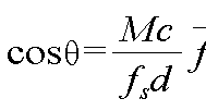
상술한 바와 같이 규격 주파수(![]()
![]()

![]()
![]()

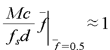
예를 들어 m=1,..., M0가 Z에 포함된다면, 영역 [-1, 1]은 M0의 서브구간으로 나뉠 것이다. 수신부 간 간격(d)는 M0가 도달할 수 있는 상한값을 조절한다. 두 신호 수신부 간 거리(d)는 다음 조건을 만족하는 값으로 정하는 것이 바람직하다. For example, if m = 1, ..., M 0 are included in Z, then region [-1, 1] will be divided into sub-intervals of M 0 . The interval (d) between receivers adjusts the upper limit that M 0 can reach. The distance d between the two signal reception units is preferably set to a value that satisfies the following condition.
본 발명의 일 실시예에 따른 도래각 측정 장치와 측정 방법을 이용하여 연산된 도래각은 FFT를 이용한 연산 과정을 통해 M, 즉 FFT의 포인트 수가 커질수록 노이즈로부터의 영향이 적어지며 측정 분산이 감소되어 전체적으로 도래각의 품질 을 향상시킨다. 아래에서는 노이즈에 의해 오염된(corrupted)된 신호에 있어 도래각의 도출을 보이고 상술한 노이즈의 영향에 대해 살펴본다.The arrival angle calculated using the arrival angle measuring apparatus and the measuring method according to the embodiment of the present invention is affected by noise as the number of points of M, i.e., FFT, is reduced through the calculation process using the FFT, Thereby improving the overall quality of the incoming angle. The following shows the derivation of the angle of arrival for the corrupted signal due to noise and the effect of the noise described above.
예를 들어, i 번째 센서에 의해 수신된 오염된 신호, yi(t)는 다음과 같이 표시된다.For example, the contaminated signal, yi (t), received by the ith sensor is expressed as:
![]()
![]()
여기서 vi(t)는 i 번째 센서의 부가 노이즈를 나타낸다. 노이즈의 간섭에 의한 영향을 도입한 후 수학식 16으로부터 수학식 25는 다음과 같이 나타낼 수 있다.Where v i (t) represents the additive noise of the i-th sensor. From the expression (16) after introducing the influence due to the interference of the noise, the expression (25) can be expressed as follows.

일반적으로 두 개의 신호, 예를 들어 i 번째 센서와 j 번째 센서에서 수신되는 두 개의 신호의 m 번째 주파수의 CPSD는 다음과 같이 계산된다.In general, the CPSD of the m-th frequency of two signals, for example the i-th sensor and the two signals received at the j-th sensor, is calculated as:

상기 수학식 27의 첫 번째 부분 식은 도래각 측정에 대한 것이고, 두 번째 부분 이후의 식은 노이즈 관련 부분으로 확실히 측정결과를 떨어뜨리지만, 노이즈 관련된 두 번째 내지 네 번째 부분의 식은 M 또는 M2에 반비례하므로 M이 클수록 노이즈로부터 영향을 감소시킬 수 있다. The first subexpression of equation (27) is for the incoming angle measurement, and the expressions after the second section definitely drop the measurement results into the noise-related part, but the expression of the second to fourth part related to noise is inversely proportional to M or M 2 Therefore, as M becomes larger, the influence from noise can be reduced.
CPSD 함수를 얻은 다음, 도래각은 Pm의 위상 부분으로부터 도래각을 검출할 수 있다. 즉,After obtaining the CPSD function, the incoming angle can detect the incoming angle from the phase part of P m . In other words,

arg(1+Vi ,m/Xi ,m)는 신호대노이즈비(SNR:Signal to Noise)에 의존하지만, 방 향성이 없는 노이즈(uncolored noise)에 있어서는 arg(1+Vj ,m/Xj ,m)과 관계가 없다. 상기 수학식 28은 위상차의 분산(variance)가 SNR의 함수임을 나타낸다. 상기 가정을 적용한다면, 타겟 신호의 도래각은 수학식 29에서 암시된다.arg (1 + V i, m / X i, m) is a signal-to-noise ratio: dependent on (SNR Signal to Noise), but, in the non-directional noise (uncolored noise) arg (1 + V j, m / X j , m ). Equation (28) indicates that the variance of the phase difference is a function of the SNR. Applying this assumption, the angle of arrival of the target signal is implied in equation (29).

수학식 29는 센서, 즉 신호 수신부 간 간격(d)의 증가는 위상차의 증가를 가져오고 또한 arg(1+Xi ,m/Xj ,m)과는 비례 관계에 있으므로, 측정 분산을 감소시켜 도래각 측정의 품질을 향상시키는 것을 나타내고 있다.Equation 29 is a sensor, that is, an increase in inter-signal receiving interval (d) is coming to an increase of the phase difference addition, since the proportion is as arg (1 + X i, m / X j, m) between, it is possible to reduce the measurement dispersion Thereby improving the quality of the arrival angle measurement.
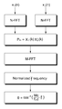
도 2는 본 발명의 일 실시예에 따라 결정된 두 개의 신호 수신부가 거리(d)만큼 이격된 경우 도래각 측정 방법을 설명하는 플로우 차트이다.FIG. 2 is a flowchart illustrating a method of measuring an arrival angle when two signal receiving units determined according to an embodiment of the present invention are spaced apart by a distance d.
두 신호 수신부에 입력된 신호(xi(n), xj(n))에 대해 N-포인트 FFT를 각각 수행하고, 크로스 파워 주파수 할당 밀도(CPSD)를 구한다. 이렇게 구한 CPSD에 대해 M-포인트 FFT를 수행한다.Point FFT on the signals x i (n) and x j (n) input to the two signal receiving units, respectively, and obtains the cross power frequency allocation density (CPSD). The M-point FFT is performed on the CPSD thus obtained.
정규 주파수 ![]()
![]()
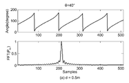
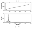
제1 및 제2 신호 수신부간 거리(d)가 어떻게 도래각 분해능을 향상시키는 지에 대한 설명이 도 3 및 도 4에 도시된다. Explanation of how the distance d between the first and second signal receiving portions improves the incoming angular resolution is shown in Figs. 3 and 4. Fig.
여기서 신호대잡음비(SNR)는 5dB 이다. 도 3은 0.5m 떨어진 두 개의 센서를 보인다. 각도에 따라 전체 부분이 4 개의 섹션으로 나뉜 것을 볼 수 있으나 단지 한 섹션으로부터의 각도 값을 결정할 수 있다. 미세한 데이터 샘플로부터는 도래각 측정에 있어 좋은 분해능을 얻기 어렵다. Here, the signal-to-noise ratio (SNR) is 5 dB. Figure 3 shows two sensors 0.5 m apart. Depending on the angle, you can see that the entire section is divided into four sections, but you can only determine the angular value from one section. It is difficult to obtain a good resolution for the arrival angle measurement from the fine data sample.
도 4에 있어, 제1 및 제2 신호 수신부간 거리(d)는 2m 확장되고 전체 부분은 각 공간의 한 주기만을 포함하므로, 도래각 측정의 정확성은 크게 향상된다.In Fig. 4, since the distance d between the first and second signal receiving units is extended by 2 m and the entire portion includes only one period of each space, the accuracy of the arrival angle measurement is greatly improved.
따라서, 본 발명의 일 실시예에 따른 도래각 측정 장치 및 방법은 단지 두 개의 센서만으로도 광대역의 정보를 이용하여 도래각을 측정할 수 있다.Therefore, the arrival angle measuring apparatus and method according to an embodiment of the present invention can measure the arrival angle using information of a wide band using only two sensors.
또한, 본 발명의 다른 일 실시예에 따른 도래각 측정 장치 및 방법은 두 단계의 FFT 연산을 통해 도래각을 도출하므로 다수의 센서로 인한 계산의 복잡성을 완화시킬 수 있다.In addition, according to another embodiment of the present invention, since the angle of incidence is derived through the two-stage FFT calculation, the calculation complexity due to the plurality of sensors can be alleviated.
이외에도, 본 발명의 다른 일 실시예에 따른 도래각 측정 장치 및 방법은 두 개의 센서 만을 이용하여 도래각을 측정하므로 센서 간 간격에 주어지던 반파장이라는 종래 기술의 상한값을 확장시켜 도래각 측정의 분해능을 높일 수 있다.In addition, according to another embodiment of the present invention, since the angle of incidence is measured using only two sensors, the upper limit value of the prior art, which is the half wavelength given to the interval between the sensors, is extended, .
본 발명의 일 실시예에 따른 방법은 다양한 컴퓨터 수단을 통하여 수행될 수 있는 프로그램 명령 형태로 구현되어 컴퓨터 판독 가능 매체에 기록될 수 있다. 상기 컴퓨터 판독 가능 매체는 프로그램 명령, 데이터 파일, 데이터 구조 등을 단독으로 또는 조합하여 포함할 수 있다. 상기 매체에 기록되는 프로그램 명령은 본 발명을 위하여 특별히 설계되고 구성된 것들이거나 컴퓨터 소프트웨어 당업자에게 공지되어 사용 가능한 것일 수도 있다. 컴퓨터 판독 가능 기록 매체의 예에는 하 드 디스크, 플로피 디스크 및 자기 테이프와 같은 자기 매체(magnetic media), CD-ROM, DVD와 같은 광기록 매체(optical media), 플롭티컬 디스크(floptical disk)와 같은 자기-광 매체(magneto-optical media), 및 롬(ROM), 램(RAM), 플래시 메모리 등과 같은 프로그램 명령을 저장하고 수행하도록 특별히 구성된 하드웨어 장치가 포함된다. 프로그램 명령의 예에는 컴파일러에 의해 만들어지는 것과 같은 기계어 코드뿐만 아니라 인터프리터 등을 사용해서 컴퓨터에 의해서 실행될 수 있는 고급 언어 코드를 포함한다. 상기된 하드웨어 장치는 본 발명의 동작을 수행하기 위해 하나 이상의 소프트웨어 모듈로서 작동하도록 구성될 수 있으며, 그 역도 마찬가지이다.The method according to an embodiment of the present invention can be implemented in the form of a program command which can be executed through various computer means and recorded in a computer-readable medium. The computer-readable medium may include program instructions, data files, data structures, and the like, alone or in combination. The program instructions recorded on the medium may be those specially designed and configured for the present invention or may be available to those skilled in the art of computer software. Examples of computer-readable media include magnetic media such as hard disks, floppy disks and magnetic tape, optical media such as CD-ROMs and DVDs, and optical disks such as floppy disks. Magneto-optical media, and hardware devices specifically configured to store and execute program instructions such as ROM, RAM, flash memory, and the like. Examples of program instructions include machine language code such as those produced by a compiler, as well as high-level language code that can be executed by a computer using an interpreter or the like. The hardware devices described above may be configured to operate as one or more software modules to perform the operations of the present invention, and vice versa.
이상과 같이 본 발명은 비록 한정된 실시예와 도면에 의해 설명되었으나, 본 발명은
상기의 실시예에 한정되는 것은 아니며, 본 발명이 속하는 분야에서 통상의 지식을 가진 자라면 이러한 기재로부터 다양한 수정 및 변형이 가능하다.While the present invention has been described in connection with certain exemplary embodiments and drawings,
It will be understood by those skilled in the art that various changes in form and details may be made therein without departing from the spirit and scope of the invention as defined by the appended claims.
그러므로, 본 발명의 범위는 설명된 실시예에 국한되어 정해져서는 아니 되며, 후술하는 특허청구범위뿐 아니라 이 특허청구범위와 균등한 것들에 의해 정해져야 한다.Therefore, the scope of the present invention should not be limited to the described embodiments, but should be determined by the equivalents of the claims, as well as the claims.
도 1은 본 발명의 일 실시예에 따른 도래각 측정 장치를 도시한 개념도,FIG. 1 is a conceptual diagram showing an arrival angle measuring apparatus according to an embodiment of the present invention,
도 2는 본 발명의 일 실시예에 따른 도래각 측정 방법을 설명하기 위한 플로우 차트,2 is a flowchart illustrating a method for measuring an arrival angle according to an embodiment of the present invention,
도 3은 두 개의 센서가 거리가 0.5m 일 때 본 발명의 일 실시예에 따른 도래각 측정 장치 및 방법을 이용하여 측정한 결과를 도시한 그래프,FIG. 3 is a graph showing a result of measurement using an apparatus and method for measuring an angle of incidence according to an embodiment of the present invention when the distance between the two sensors is 0.5 m,
도 4는 두 개의 센서가 거리가 2m 일 때 본 발명의 일 실시예에 따른 도래각 측정 장치 및 방법을 이용하여 측정한 결과를 도시한 그래프.FIG. 4 is a graph showing a result of measurement using an apparatus for measuring an angle of incidence according to an embodiment of the present invention when the distance between two sensors is 2 m.
Claims (8)


Priority Applications (2)
| Application Number | Priority Date | Filing Date | Title |
|---|---|---|---|
| KR1020090052563A KR101562904B1 (en) | 2009-06-12 | 2009-06-12 | Direction of Arrival Estimation Apparatus and Method therof |
| US12/760,360 US8531917B2 (en) | 2009-06-12 | 2010-04-14 | Direction of arrival estimation apparatus and method thereof |
Applications Claiming Priority (1)
| Application Number | Priority Date | Filing Date | Title |
|---|---|---|---|
| KR1020090052563A KR101562904B1 (en) | 2009-06-12 | 2009-06-12 | Direction of Arrival Estimation Apparatus and Method therof |
Publications (2)
| Publication Number | Publication Date |
|---|---|
| KR20100133830A KR20100133830A (en) | 2010-12-22 |
| KR101562904B1 true KR101562904B1 (en) | 2015-10-23 |
Family
ID=43305982
Family Applications (1)
| Application Number | Title | Priority Date | Filing Date |
|---|---|---|---|
| KR1020090052563A KR101562904B1 (en) | 2009-06-12 | 2009-06-12 | Direction of Arrival Estimation Apparatus and Method therof |
Country Status (2)
| Country | Link |
|---|---|
| US (1) | US8531917B2 (en) |
| KR (1) | KR101562904B1 (en) |
Families Citing this family (18)
| Publication number | Priority date | Publication date | Assignee | Title |
|---|---|---|---|---|
| US9001621B2 (en) | 2012-04-20 | 2015-04-07 | Symbol Technologies, Inc. | Dual frequency ultrasonic locationing system |
| US9151826B2 (en) * | 2012-06-08 | 2015-10-06 | Symbol Technologies, Llc | Locationing via phase difference correlation between two frequency pulses derived from a single frequency emitter ultrasonic burst |
| CN103236885A (en) * | 2013-03-19 | 2013-08-07 | 南京大学 | Ultra-wideband zero-frequency-dispersion DOA (direction of arrival) estimation method and device |
| US9588213B2 (en) * | 2014-02-18 | 2017-03-07 | Raytheon Company | Analog signal processing method for accurate single antenna direction finding |
| US9590760B2 (en) | 2014-06-03 | 2017-03-07 | Raytheon Company | Analog RF memory system |
| US9485125B2 (en) | 2014-06-16 | 2016-11-01 | Raytheon Company | Dynamically reconfigurable channelizer |
| US9645972B2 (en) | 2014-06-16 | 2017-05-09 | Raytheon Company | Butterfly channelizer |
| US10027026B2 (en) | 2014-09-18 | 2018-07-17 | Raytheon Company | Programmable beamforming system including element-level analog channelizer |
| CN104391268B (en) * | 2014-11-21 | 2017-10-13 | 哈尔滨工业大学深圳研究生院 | A kind of ripple reaches azimuthal detection method |
| KR102364688B1 (en) | 2015-11-13 | 2022-02-21 | 한국전자통신연구원 | Apparatus and method for estimating parameter of multi path signal |
| CN105445718B (en) * | 2015-11-19 | 2018-01-26 | 哈尔滨工业大学 | A kind of DOA estimation method of the distributed overloading warship over-the-horizon radar based on array reconfiguration |
| CN106331079A (en) * | 2016-08-19 | 2017-01-11 | 明算科技(北京)股份有限公司 | DOA (Data Oriented Architecture) system |
| CN106226754B (en) * | 2016-08-22 | 2019-03-29 | 西安电子科技大学 | Low elevation angle Wave arrival direction estimating method based on time reversal |
| US10348338B2 (en) | 2016-10-06 | 2019-07-09 | Raytheon Company | Adaptive channelizer |
| US10084587B1 (en) | 2017-07-28 | 2018-09-25 | Raytheon Company | Multifunction channelizer/DDC architecture for a digital receiver/exciter |
| CN108562866B (en) * | 2018-04-04 | 2022-06-14 | 长江大学 | Bistatic MIMO radar angle estimation method based on matrix filling |
| CN109239645A (en) * | 2018-08-27 | 2019-01-18 | 西安电子科技大学 | Multiple groups wide-band coherent signal Wave arrival direction estimating method under multipath effect |
| CN110531311A (en) * | 2019-08-27 | 2019-12-03 | 武汉大学深圳研究院 | A kind of LTE external illuminators-based radar DOA estimation method based on matrix recombination |
Citations (4)
| Publication number | Priority date | Publication date | Assignee | Title |
|---|---|---|---|---|
| JP2007225544A (en) | 2006-02-27 | 2007-09-06 | Advanced Telecommunication Research Institute International | Arrival direction estimating device |
| WO2008059476A1 (en) * | 2006-11-12 | 2008-05-22 | Elta Systems Ltd. | Method and system for detecting signal sources in a surveillance space |
| JP2008271222A (en) * | 2007-04-20 | 2008-11-06 | Nippon Hoso Kyokai <Nhk> | Multipath incoming direction measuring device |
| JP2008300937A (en) | 2007-05-29 | 2008-12-11 | Sony Corp | Arrival angle estimation system, communication device, and communication system |
Family Cites Families (5)
| Publication number | Priority date | Publication date | Assignee | Title |
|---|---|---|---|---|
| US5444451A (en) * | 1992-06-29 | 1995-08-22 | Southwest Research Institute | Passive means for single site radio location |
| DE19753932A1 (en) | 1997-12-05 | 1999-06-10 | Cit Alcatel | Method for determining the direction of reception by means of a group antenna, base station and radio system |
| JP2001305202A (en) | 2000-04-24 | 2001-10-31 | Toyota Central Res & Dev Lab Inc | Music spectrum computation method, and its device and medium |
| KR101126712B1 (en) | 2006-01-03 | 2012-03-29 | 삼성전자주식회사 | Appratus and method for antenna which estimates direction of arrival and frequency of arrival |
| US8004463B2 (en) | 2007-11-19 | 2011-08-23 | Raytheon Company | Systems and methods for determining direction-of-arrival |
-
2009
- 2009-06-12 KR KR1020090052563A patent/KR101562904B1/en not_active IP Right Cessation
-
2010
- 2010-04-14 US US12/760,360 patent/US8531917B2/en not_active Expired - Fee Related
Patent Citations (4)
| Publication number | Priority date | Publication date | Assignee | Title |
|---|---|---|---|---|
| JP2007225544A (en) | 2006-02-27 | 2007-09-06 | Advanced Telecommunication Research Institute International | Arrival direction estimating device |
| WO2008059476A1 (en) * | 2006-11-12 | 2008-05-22 | Elta Systems Ltd. | Method and system for detecting signal sources in a surveillance space |
| JP2008271222A (en) * | 2007-04-20 | 2008-11-06 | Nippon Hoso Kyokai <Nhk> | Multipath incoming direction measuring device |
| JP2008300937A (en) | 2007-05-29 | 2008-12-11 | Sony Corp | Arrival angle estimation system, communication device, and communication system |
Also Published As
| Publication number | Publication date |
|---|---|
| US20100315292A1 (en) | 2010-12-16 |
| US8531917B2 (en) | 2013-09-10 |
| KR20100133830A (en) | 2010-12-22 |
Similar Documents
| Publication | Publication Date | Title |
|---|---|---|
| KR101562904B1 (en) | Direction of Arrival Estimation Apparatus and Method therof | |
| KR101548848B1 (en) | Systems, methods, apparatus, and computer-readable media for source localization using audible sound and ultrasound | |
| EP3090275B1 (en) | Microphone autolocalization using moving acoustic source | |
| US8213263B2 (en) | Apparatus and method of detecting target sound | |
| US9229086B2 (en) | Sound source localization apparatus and method | |
| US9961460B2 (en) | Vibration source estimation device, vibration source estimation method, and vibration source estimation program | |
| US9351071B2 (en) | Audio source position estimation | |
| KR101529516B1 (en) | Sound sourcelocalization device and sound sourcelocalization method | |
| EP3210391B1 (en) | Reverberation estimator | |
| Lee et al. | The array invariant | |
| US20150338517A1 (en) | Proximity Detecting Apparatus And Method Based On Audio Signals | |
| Wang et al. | {MAVL}: Multiresolution analysis of voice localization | |
| US11930331B2 (en) | Method, apparatus and device for processing sound signals | |
| US20190228790A1 (en) | Sound source localization method and sound source localization apparatus based coherence-to-diffuseness ratio mask | |
| US7397427B1 (en) | Phase event detection and direction of arrival estimation | |
| KR20210060844A (en) | Method and apparatus for measuting position of three dimensions using radar sensor | |
| KR101988109B1 (en) | Method for estimating position of signal source using distance estimation in mimo system | |
| CN108957389A (en) | A kind of real number field multi channel signals method for estimating target azimuth | |
| KR102132296B1 (en) | A target detection apparatus and method using the fmcw radar | |
| JP3862685B2 (en) | Sound source direction estimating device, signal time delay estimating device, and computer program | |
| KR102471995B1 (en) | Method and apparatus for estimating the number of signals, by considering SML cost function and hypothesis test | |
| KR101524550B1 (en) | Method and Apparatus for a fast Linear Frequency Modulation target detection compensating Doppler effect according to the target speed | |
| CN113126029A (en) | Multi-sensor pulse sound source positioning method suitable for deep sea reliable acoustic path environment | |
| KR101534781B1 (en) | Apparatus and method for estimating sound arrival direction | |
| KR100846446B1 (en) | Apparatus for estimation of alternating projection searching and method thereof |
Legal Events
| Date | Code | Title | Description |
|---|---|---|---|
| A201 | Request for examination | ||
| E902 | Notification of reason for refusal | ||
| E701 | Decision to grant or registration of patent right | ||
| GRNT | Written decision to grant | ||
| LAPS | Lapse due to unpaid annual fee |