KR100922419B1 - Diffuse sound envelope shaping for Binural Cue coding schemes and the like - Google Patents
Diffuse sound envelope shaping for Binural Cue coding schemes and the like Download PDFInfo
- Publication number
- KR100922419B1 KR100922419B1 KR1020077008796A KR20077008796A KR100922419B1 KR 100922419 B1 KR100922419 B1 KR 100922419B1 KR 1020077008796 A KR1020077008796 A KR 1020077008796A KR 20077008796 A KR20077008796 A KR 20077008796A KR 100922419 B1 KR100922419 B1 KR 100922419B1
- Authority
- KR
- South Korea
- Prior art keywords
- signal
- audio signal
- input
- envelope
- channels
- Prior art date
Links
- 238000007493 shaping process Methods 0.000 title claims abstract description 40
- 230000002123 temporal effect Effects 0.000 claims abstract description 34
- 230000005236 sound signal Effects 0.000 claims description 94
- 238000000034 method Methods 0.000 claims description 87
- 238000012545 processing Methods 0.000 claims description 60
- 230000015572 biosynthetic process Effects 0.000 claims description 49
- 238000003786 synthesis reaction Methods 0.000 claims description 49
- 230000001052 transient effect Effects 0.000 claims description 25
- 238000004458 analytical method Methods 0.000 claims description 11
- 238000001514 detection method Methods 0.000 claims description 10
- 230000005540 biological transmission Effects 0.000 claims description 9
- 230000008569 process Effects 0.000 claims description 9
- 230000002194 synthesizing effect Effects 0.000 claims description 3
- 230000002596 correlated effect Effects 0.000 claims 3
- 238000004590 computer program Methods 0.000 claims 1
- 230000000875 corresponding effect Effects 0.000 claims 1
- 238000010586 diagram Methods 0.000 description 25
- 230000006870 function Effects 0.000 description 14
- 230000003595 spectral effect Effects 0.000 description 9
- 239000003795 chemical substances by application Substances 0.000 description 8
- 238000001914 filtration Methods 0.000 description 7
- 238000001308 synthesis method Methods 0.000 description 5
- 238000004422 calculation algorithm Methods 0.000 description 4
- 230000001419 dependent effect Effects 0.000 description 4
- 210000005069 ears Anatomy 0.000 description 4
- 239000011159 matrix material Substances 0.000 description 4
- 230000002441 reversible effect Effects 0.000 description 4
- 238000012935 Averaging Methods 0.000 description 3
- 238000004364 calculation method Methods 0.000 description 3
- 239000002131 composite material Substances 0.000 description 3
- 230000000694 effects Effects 0.000 description 3
- 230000004807 localization Effects 0.000 description 3
- 238000012546 transfer Methods 0.000 description 3
- 238000013459 approach Methods 0.000 description 2
- 210000004556 brain Anatomy 0.000 description 2
- 230000008859 change Effects 0.000 description 2
- 238000012937 correction Methods 0.000 description 2
- 230000001934 delay Effects 0.000 description 2
- 238000005516 engineering process Methods 0.000 description 2
- 210000003128 head Anatomy 0.000 description 2
- 230000008447 perception Effects 0.000 description 2
- 238000001228 spectrum Methods 0.000 description 2
- 210000003454 tympanic membrane Anatomy 0.000 description 2
- 230000009471 action Effects 0.000 description 1
- 230000003044 adaptive effect Effects 0.000 description 1
- 230000003321 amplification Effects 0.000 description 1
- 238000005311 autocorrelation function Methods 0.000 description 1
- 230000008901 benefit Effects 0.000 description 1
- ZYXYTGQFPZEUFX-UHFFFAOYSA-N benzpyrimoxan Chemical compound O1C(OCCC1)C=1C(=NC=NC=1)OCC1=CC=C(C=C1)C(F)(F)F ZYXYTGQFPZEUFX-UHFFFAOYSA-N 0.000 description 1
- 238000012512 characterization method Methods 0.000 description 1
- 230000006835 compression Effects 0.000 description 1
- 238000007906 compression Methods 0.000 description 1
- 238000005314 correlation function Methods 0.000 description 1
- 230000008878 coupling Effects 0.000 description 1
- 238000010168 coupling process Methods 0.000 description 1
- 238000005859 coupling reaction Methods 0.000 description 1
- 230000006837 decompression Effects 0.000 description 1
- 230000003111 delayed effect Effects 0.000 description 1
- 238000009795 derivation Methods 0.000 description 1
- 238000013461 design Methods 0.000 description 1
- 230000009365 direct transmission Effects 0.000 description 1
- 230000005670 electromagnetic radiation Effects 0.000 description 1
- 230000002452 interceptive effect Effects 0.000 description 1
- 239000000463 material Substances 0.000 description 1
- 238000000691 measurement method Methods 0.000 description 1
- 238000012986 modification Methods 0.000 description 1
- 230000004048 modification Effects 0.000 description 1
- 238000010606 normalization Methods 0.000 description 1
- 238000003199 nucleic acid amplification method Methods 0.000 description 1
- 239000013307 optical fiber Substances 0.000 description 1
- 230000000399 orthopedic effect Effects 0.000 description 1
- 238000009527 percussion Methods 0.000 description 1
- 238000013139 quantization Methods 0.000 description 1
- 230000009467 reduction Effects 0.000 description 1
- 230000004044 response Effects 0.000 description 1
- 238000005070 sampling Methods 0.000 description 1
- 239000004065 semiconductor Substances 0.000 description 1
- 230000008054 signal transmission Effects 0.000 description 1
- 238000004088 simulation Methods 0.000 description 1
- 230000007480 spreading Effects 0.000 description 1
- 238000006467 substitution reaction Methods 0.000 description 1
Images


Classifications
-
- G—PHYSICS
- G10—MUSICAL INSTRUMENTS; ACOUSTICS
- G10L—SPEECH ANALYSIS TECHNIQUES OR SPEECH SYNTHESIS; SPEECH RECOGNITION; SPEECH OR VOICE PROCESSING TECHNIQUES; SPEECH OR AUDIO CODING OR DECODING
- G10L19/00—Speech or audio signals analysis-synthesis techniques for redundancy reduction, e.g. in vocoders; Coding or decoding of speech or audio signals, using source filter models or psychoacoustic analysis
- G10L19/008—Multichannel audio signal coding or decoding using interchannel correlation to reduce redundancy, e.g. joint-stereo, intensity-coding or matrixing
-
- H—ELECTRICITY
- H04—ELECTRIC COMMUNICATION TECHNIQUE
- H04S—STEREOPHONIC SYSTEMS
- H04S3/00—Systems employing more than two channels, e.g. quadraphonic
-
- H—ELECTRICITY
- H04—ELECTRIC COMMUNICATION TECHNIQUE
- H04S—STEREOPHONIC SYSTEMS
- H04S3/00—Systems employing more than two channels, e.g. quadraphonic
- H04S3/02—Systems employing more than two channels, e.g. quadraphonic of the matrix type, i.e. in which input signals are combined algebraically, e.g. after having been phase shifted with respect to each other
Landscapes
- Engineering & Computer Science (AREA)
- Physics & Mathematics (AREA)
- Signal Processing (AREA)
- Acoustics & Sound (AREA)
- Mathematical Physics (AREA)
- Computational Linguistics (AREA)
- Health & Medical Sciences (AREA)
- Audiology, Speech & Language Pathology (AREA)
- Human Computer Interaction (AREA)
- Multimedia (AREA)
- Mathematical Analysis (AREA)
- Algebra (AREA)
- Mathematical Optimization (AREA)
- Pure & Applied Mathematics (AREA)
- Theoretical Computer Science (AREA)
- General Physics & Mathematics (AREA)
- Stereophonic System (AREA)
- Tone Control, Compression And Expansion, Limiting Amplitude (AREA)
- Compression, Expansion, Code Conversion, And Decoders (AREA)
- Golf Clubs (AREA)
- Diaphragms For Electromechanical Transducers (AREA)
- Television Systems (AREA)
- Control Of Amplification And Gain Control (AREA)
- Signal Processing Not Specific To The Method Of Recording And Reproducing (AREA)
- Electrophonic Musical Instruments (AREA)
Abstract
Description
본 발명은 오디오신호의 인코딩 방법 및 그 인코딩된 오디오 데이터로부터 청각적 장면을 합성하는 방법에 관한 것이다.The present invention relates to a method for encoding an audio signal and a method for synthesizing a blue scene from the encoded audio data.
관련 출원의 상호 참조Cross Reference of Related Application
본 출원은 2004. 10. 20.자 미합중국 가특허출원 제 60/620,401호 (대리인 명부 번호 Allamanche 1-2-17-3)에 대해 우선권 주장이 있으며, 이 출원의 개시 내용은 본 명세서에 참고로 통합되었다.This application claims priority to US Provisional Patent Application No. 60 / 620,401, Representative Listing No. Allamanche 1-2-17-3, filed on October 20, 2004, the disclosure of which is incorporated herein by reference. Integrated.
부가적으로, 본 출원의 주제는 이하의 미합중국 특허출원의 주제와 관련이 있으며, 그 개시 내용 또한 본 명세서에 참고로 혼합되어 있다:In addition, the subject matter of this application is related to the subject matter of the following United States patent applications, the disclosure content of which is also incorporated herein by reference:
o 2001. 5. 4.자 미합중국 특허출원 제 09/848,877호 (대리인 명부 번호 Faller 5),o US Patent Application Serial No. 09 / 848,877 filed on May 4, 2001 (Agent No. Faller 5),
o 2001. 11. 7.자 미합중국 특허출원 제 09/848,877호 (대리인 명부 번호 Baumgarte 1-6-8); 2001. 8. 10.자 미합중국 가특허출원 제 60/311,565호에 대 해 우선권 주장을 함,o US Patent Application Serial No. 09 / 848,877 filed on November 7, 2001 (Agent No. Baumgarte 1-6-8); Of the United States of America Patent Application No. 60 / 311,565 issued on August 10, 2001,
o 2002. 5. 24.자 미합중국 특허출원 제 10/155,437호 (대리인 명부 번호 Baumgarte 2-10),o US Patent Application No. 10 / 155,437 dated May 24, 2002 (Agent Listing Number Baumgarte 2-10),
o 2002. 9. 18.자 미합중국 특허출원 제 10/246,570호 (대리인 명부 번호 Baumgarte 3-11),o US patent application Ser. No. 10 / 246,570 dated September 18, 2002 (agent list number Baumgarte 3-11),
o 2004. 4. 1.자 미합중국 특허출원 제 10/815,591호 (대리인 명부 번호 Baumgarte 7-12),o United States Patent Application No. 10 / 815,591 dated April 1, 2004 (Agent Listing Number Baumgarte 7-12),
o 2004. 9. 8.자 미합중국 특허출원 제 10/936,464호 (대리인 명부 번호 Baumgarte 8-7-15),o US patent application Ser. No. 10 / 936,464 dated Sept. 8, 2004 (agent list number Baumgarte 8-7-15),
o 2004. 1. 20.자 미합중국 특허출원 제 10/762,100호 (대리인 명부 번호 Faller 13-1), 및o US Patent Application No. 10 / 762,100 dated Jan. 20, 2004 (Agent No. Faller 13-1), and
o 본 출원과 동일자 미합중국 특허출원 제 10/xxx,xxx호 (대리인 명부 번호 Allamanche 2-3-18-4).o United States Patent Application No. 10 / xxx, xxx, the same as the present application, Representative Directory No. Allamanche 2-3-18-4.
본 출원의 주제는 또한 다음의 논문에 기술된 주제와 관련이 있고 그 개시된 내용은 본 명세서에 참고로 병합되었다:The subject matter of the present application also relates to the subject matter described in the following papers, the disclosure content of which is incorporated herein by reference:
o F. Baumgarte and C. Faller, "Binaural Cue Coding - Part I: Psychoacoustic fundamentals and design principles," IEEE Trans . on Speech and Audio Proc ., vol. 11, no. 6, Nov. 2003;o F. Baumgarte and C. Faller, "Binaural Cue Coding-Part I: Psychoacoustic fundamentals and design principles," IEEE Trans . on Speech and Audio Proc . , vol. 11, no. 6, Nov. 2003;
o C. Faller and F. Baumgarte, "Binaural Cue Coding - Part II: Schemes and applications," IEEE Trans . on Speech and Audio Proc ., vol. 11, no. 6, Nov. 2003; 및C. Faller and F. Baumgarte, "Binaural Cue Coding-Part II: Schemes and applications," IEEE Trans . on Speech and Audio Proc . , vol. 11, no. 6, Nov. 2003; And
o C. Faller, "Coding of spatial audio compatible with different playback formats," Preprint 117 th Conv . Aud . Eng . Soc ., October 2004.o C. Faller, "Coding of spatial audio compatible with different playback formats," Preprint 117 th Conv . Aud . Eng . Soc . , October 2004.
관련 기술의 설명Description of the related technology
사람이 특정한 음원에서 발생한 오디오 신호(즉, 소리)를 듣게 될 때, 그 오디오 신호는 사람의 좌측 및 우측 귀에 둘의 서로 다른 때에 그리고 둘의 서로 다른 오디오레벨(예를 들어, 데시벨)을 가지고 도달한다. 이들 서로 다른 시간 및 레벨은 각각 오디오 신호가 좌측 및 우측 귀로 도달하기 위한 이동 경로의 차이에 대한 함수이다. 사람의 뇌는 이 시간과 레벨의 차이를 해석하여 수신된 오디오 신호가 사람에 대한 특정한 위치(예를 들어, 방향 및 거리)에 있는 음원에 의해 발생되고 있다는 것을 지각하게 한다. '청각적 장면'은 결국 사람에 대해 하나 또는 그 이상의 위치에 놓인 하나 또는 그 이상의 서로 다른 음원에서 발생한 오디오 신호를 사람이 동시에 듣는 효과를 의미한다. When a person hears an audio signal (i.e. sound) from a particular sound source, the audio signal arrives at the person's left and right ears at two different times and with two different audio levels (e.g. decibels). do. These different times and levels are a function of the difference in travel paths for the audio signal to reach the left and right ears, respectively. The human brain interprets the difference between this time and the level to make it sense that the received audio signal is being generated by a sound source at a specific location (eg, direction and distance) to the person. 'Audible scene' refers to the effect of a person simultaneously listening to an audio signal from one or more different sound sources placed in one or more positions relative to a person.
사람의 뇌에서 행하는 위와 같은 처리는 청각적 장면을 합성하는데 사용될 수 있다. 즉, 하나 또는 그 이상의 서로 다른 음원에서 발생한 오디오신호를 의도적으로 수정하여 좌측 및 우측 오디오신호를 생성하고, 이에 의해 서로 다른 음원이 청취자에 대해 서로 다른 위치에 놓인 것으로 지각하게 하는 것이다.The above processing in the human brain can be used to synthesize an auditory scene. In other words, the audio signals generated from one or more different sound sources are intentionally modified to generate left and right audio signals, whereby different sound sources are perceived as being placed at different positions with respect to the listener.
도 1은 종래의 바이노럴 신호 합성기(100)의 블록 다이어그램을 나타낸다. 이 합성기(100)는 단일 음원 신호(예를 들어, 모노 신호)를 바이노럴 신호의 좌측 및 우측 오디오신호로 변환한다. 여기서, 바이노럴 신호는 청취자의 고막에서 수신된 2개 신호로서 정의된다. 음원 신호에 부가하여, 합성기(100)는 일단의 공간 큐 신호를 수신한다. 공간 큐(cue)는 청취자에 대한 음원의 희망 위치를 지시한다. 통상적인 실시에서, 일단의 공간 큐는 채널간 레벨 차(ICLD) 값(좌측 및 우측 귀 각각 에서 수신한 것과 같은 좌측 및 우측 오디오 신호 간의 오디오레벨 차이를 식별)과 채널간 시간 차(ICTD) 값(좌측 및 우측 귀 각각에 수신되는 좌측 및 우측 오디오 신호의 도달 시간 차를 식별)을 포함한다. 부가적으로 또는 대안적으로, 합성기는 헤드 관련 전달 함수(HRTF)라고 칭하는, 음원으로부터 고막까지의 오디오신호에 대한 방향종속 전달 함수를 모형화하는 합성 기술을 사용할 수 있다. 헤드 관련 전달 함수(HRTF)는 예를 들어 논문, J. Blauert, "The Psychophysics of Human Sound Localization", MIT Press, 1983 을 참고할 수 있으며 그 개시 내용은 여기에 참고로 통합되어 있다.1 shows a block diagram of a conventional
도 1의 바이노럴 신호 합성기(100)에서, 단일 음원에서 발생한 모노 오디오신호는 헤드폰으로 청취할 경우 적절한 공간 큐 세트(예를 들어, ICLD, ICTD 및/또는 HRTF)를 가함에 의해 음원이 공간적으로 배치되게 하고 이에 따라 각 귀에 대한 오디오신호를 발생하는 방식으로 처리될 수 있다. 이에 대해서는 예를 들어 논문, D.R. Begault, "3-D Sound for Virtual Reality and Multimedia", Academic Press, Cambridge, MA, 1994,를 참고할 수 있다.In the
도 1의 바이노럴 신호 합성기(100)는 단일의 음원이 청취자에 대해 놓이는 가장 단순한 형태의 청각적 장면을 연출한다. 청취자에 대해 서로 다른 위치로 놓 이는 둘 또는 그 이상의 음원을 포함하는 더 복잡한 청각적 장면은 청각 장면 합성기를 사용하여 생성될 수 있다. 청각 장면 합성기는 기본적으로 여러 단계의 바이노럴 신호 합성기를 사용하여 실시되고, 각각의 바이노럴 신호 합성기는 서로 다른 음원에 대응하는 바이노럴 신호를 생성한다. 각각의 서로 다른 음원이 청취자에 대해 서로 다른 위치를 가지기 때문에, 서로 다른 음원 각각에 대한 바이노럴 오디오신호를 발생하기 위해서 서로 다른 공간 큐 세트가 사용된다.The
하나의 실시예에 따르면, 본 발명은 입력 시간 엔벌로프를 갖는 입력 오디오신호를 출력 시간 엔벌로프를 가진 출력 오디오신호로 변환하기 위한 방법 및 장치에 관한다. 입력 오디오신호의 입력 시간 엔벌로프가 특징 지워진다. 입력 오디오신호는 처리된 오디오신호를 생성하도록 처리된다. 여기서 처리는 입력 오디오신호의 상관관계를 해제시키는 것이다. 처리된 오디오신호를 특징 지워진 입력 시간 엔벌로프에 근거하여 조정함으로써 출력 오디오신호를 생성한다. 이때 출력 시간 엔벌로프는 입력 시간 엔벌로프에 실질적으로 정합된다. According to one embodiment, the present invention is directed to a method and apparatus for converting an input audio signal having an input time envelope into an output audio signal having an output time envelope. The input time envelope of the input audio signal is characterized. The input audio signal is processed to produce a processed audio signal. The process here is to uncorrelate the input audio signal. The output audio signal is generated by adjusting the processed audio signal based on the characterized input time envelope. The output time envelope is then substantially matched to the input time envelope.
다른 실시예에 따르면, 본 발명은 C개 입력 오디오채널을 인코딩하여 E개의 전송된 오디오채널(들)을 생성하기 위한 방법 및 장치에 관한다. 하나 또는 그 이상의 큐 코드가 2개 또는 그 이상의 C 입력 채널에 대해 생성된다. C개 입력 채널이 다운믹싱되어 E개의 전송 채널이 생성된다(여기서 C>E≥1). 하나 또는 그 이상의 C개 입력 채널과 E개의 전송 채널(들)이 분석되어 E개 전송 채널의 디코더가 그 E개 전송채널을 디코딩할 때 엔벌로프 정형을 수행할지 여부를 나타내는 플래그가 생성된다. According to another embodiment, the present invention is directed to a method and apparatus for encoding C input audio channels to generate E transmitted audio channel (s). One or more cue codes are generated for two or more C input channels. C input channels are downmixed to produce E transport channels (where C > E > 1). One or more C input channels and E transport channel (s) are analyzed to generate a flag indicating whether or not the decoder of the E transport channels performs envelope shaping when decoding the E transport channels.
다른 실시예에 따르면, 본 발명은 전술한 본 발명의 방법에 의해 생성된 인코딩된 오디오 비트스트림에 관한다.According to another embodiment, the invention relates to an encoded audio bitstream generated by the method of the invention described above.
다른 실시예에 따르면, 본 발명은 E개의 전송 오디오채널(들)과, 하나 또는 그 이상의 큐 코드와, 그리고 플래그를 포함하는 인코딩된 오디오 비트스트림에 관한다. 하나 또는 그 이상의 큐 코드는 2개 또는 그 이상의 C 입력 채널에 대해 하나 또는 그 이상의 큐 코드를 생성하는 것에 의해 생성된다. E개의 전송 채널(들)은 C개 입력 채널을 다운믹싱하는 것에 의해 생성된다(여기서 C>E≥1). 플래그는 하나 또는 그 이상의 C개 입력 채널과 E개의 전송 채널(들)을 분석하는 것에 의해 생성되고, 그 플래그는 E개 전송 채널의 디코더가 그 E개 전송채널을 디코딩하는 중에 엔벌로프 정형을 수행해야할지 여부를 나타낸다. According to another embodiment, the present invention relates to an encoded audio bitstream comprising E transport audio channel (s), one or more cue codes, and flags. One or more cue codes are generated by generating one or more cue codes for two or more C input channels. E transport channel (s) are created by downmixing C input channels (where C > E > 1). The flag is generated by analyzing one or more C input channels and E transport channel (s), and the flag performs envelope shaping while the decoder of E transport channels decodes the E transport channels. Indicate whether or not it should.
본 발명의 다른 양상, 특징, 이점들은 이하의 상세한 설명과 청구범위 그리고 동일한 도면의 참조 부호가 동일 또는 유사한 요소를 밝히는 첨부 도면으로부터 더욱 충분히 알 수 있게 된다.Other aspects, features, and advantages of the present invention will become more fully apparent from the following detailed description and claims, and from the accompanying drawings in which like reference characters in the same drawings identify the same or similar elements.
도 1은 종래의 바이노럴 신호 합성기의 고차적 블록 다이어그램.1 is a high-order block diagram of a conventional binaural signal synthesizer.
도 2는 일반적인 바이노럴 큐 코딩(BCC) 오디오처리 시스템의 블록 다이어그램.2 is a block diagram of a typical binaural cue coding (BCC) audio processing system.
도 3은 도 2의 다운믹서로서 사용될 수 있는 다운믹서의 블록 다이어그램.3 is a block diagram of a downmixer that may be used as the downmixer of FIG.
도 4는 도 2의 디코더로서 사용될 수 있는 BCC 합성기의 블록 다이어그램.4 is a block diagram of a BCC synthesizer that may be used as the decoder of FIG.
도 5는 본 발명의 하나의 실시예에 따른 도 2의 BCC 추정기에 대한 블록 다이어그램.5 is a block diagram of the BCC estimator of FIG. 2 in accordance with an embodiment of the present invention.
도 6은 5채널 오디오에 대한 ICTD 및 ICLD 데이터의 발생 원리를 나타내는 개념도.6 is a conceptual diagram showing a generation principle of ICTD and ICLD data for 5-channel audio.
도 7은 5채널 오디오에 대한 ICC 데이터의 발생 원리를 나타내는 개념도.7 is a conceptual diagram showing a generation principle of ICC data for 5-channel audio.
도 8은 단일 전송 합 신호 s(n)와 부가적 공간 큐를 가진 스테레오 또는 다채널 오디오신호를 발생하기 위해 BCC 디코더에서 사용될 수 있는 도 4의 BCC 합성기의 실시예를 나타낸 블록 다이어그램.8 is a block diagram illustrating an embodiment of the BCC synthesizer of FIG. 4 that may be used in a BCC decoder to generate a stereo or multichannel audio signal having a single transmit sum signal s (n) and an additional spatial cue.
도 9는 ICTD 및 ICLD가 서브밴드에서 주파수의 함수로서 어떻게 변화하는 지를 나타낸 그래프.9 is a graph showing how ICTD and ICLD change as a function of frequency in subbands.
도 10은 본 발명의 하나의 실시예에 따라 BCC 디코더의 일부분을 나타내는 블록 다이어그램.10 is a block diagram illustrating a portion of a BCC decoder in accordance with one embodiment of the present invention.
도 11은 도 4의 BCC 합성기에 관련하여 도 10의 엔벌로프 정형 방법에 대한 적용 예를 나타낸 도면.FIG. 11 illustrates an application example to the envelope shaping method of FIG. 10 in relation to the BCC synthesizer of FIG. 4. FIG.
도 12는 도 4의 BCC 합성기에 관련하여 도 10의 엔벌로프 정형 방법에 대한 다른 적용 예를 나타낸 것으로, 엔벌로프 정형은 시간 영역에서 적용된다.FIG. 12 illustrates another application example of the envelope shaping method of FIG. 10 in relation to the BCC synthesizer of FIG. 4, wherein the envelope shaping is applied in the time domain.
도 13의(A) 및 (B)는 도 12의 TPA 및 TP에 대한 가능한 실시예를 나타낸 것 으로, 엔벌로프 정형은 차단 주파수 fTP 보다 높은 주파수에만 적용된다.13A and 13B show possible embodiments of the TPA and TP of FIG. 12, where the envelope shaping is applied only to frequencies higher than the cutoff frequency f TP .
도 14는 미합중국 특허출원 제 10/815,591호에 기재된 지연 잔향 기반 ICC 합성 방법에 관련하여 도 10의 엔벌로프 정형 방법의 적용 예를 나타낸 도면.FIG. 14 illustrates an application example of the envelope shaping method of FIG. 10 in relation to the delay reverberation based ICC synthesis method described in US Patent Application No. 10 / 815,591. FIG.
도 15는 도 10에 나타낸 방법과 대체될 수 있는 본 발명의 실시예에 따라 BCC 인코더의 적어도 일부분을 나타내는 블록 다이어그램.FIG. 15 is a block diagram illustrating at least a portion of a BCC encoder in accordance with an embodiment of the present invention that may be substituted for the method shown in FIG. 10. FIG.
도 16은 도 10 및 도 15에 나타낸 방법과 대체될 수 있는 본 발명의 실시예에 따른 BCC 인코더의 적어도 일부분을 나타내는 블록 다이어그램.16 is a block diagram illustrating at least a portion of a BCC encoder in accordance with an embodiment of the present invention that may be substituted for the method shown in FIGS. 10 and 15.
도 17은 도 4의 BCC 합성기에 관련하여 도 15의 엔벌로프 정형 방법의 적용 예를 나타낸 도면.FIG. 17 illustrates an example of applying the envelope shaping method of FIG. 15 in relation to the BCC synthesizer of FIG. 4. FIG.
도 18(A)-(C)는 도 17의 TPA, ITP 및 TP의 가능한 실시 예를 나타낸 블록 다이어그램.18 (A)-(C) are block diagrams illustrating possible embodiments of the TPA, ITP, and TP of FIG. 17.
바이노럴 큐 코딩(BCC) 방법에서, 인코더는 C개 입력 오디오 채널을 인코딩하여 E개의 전송 오디오 채널을 발생한다 (여기서C>E≥1). 특히, 2개 또는 그 이상의 C 입력 채널은 주파수 영역으로 제공되고, 하나 또는 그 이상의 큐 코드가 주파수 영역에서 2개 또는 그 이상의 입력 채널의 하나 또는 그 이상의 서로 다른 주파수 밴드 각각에 대해 생성된다. 부가적으로, C개 입력 채널은 다운믹싱되어 E개 전송 채널을 생성한다. 다운믹싱 방법에 있어서, 적어도 하나의 E개 전송 채널이 2 개 또는 그 이상의 C 입력 채널에 기반을 두고 실시되는 경우도 있고, 적어도 하나의 E개 전송 채널이 단지 하나의 C 입력 채널에 기반을 둔 것도 있다.In the binaural cue coding (BCC) method, the encoder encodes C input audio channels to generate E transmission audio channels (where C > E > 1). In particular, two or more C input channels are provided in the frequency domain, and one or more cue codes are generated for each of one or more different frequency bands of two or more input channels in the frequency domain. In addition, the C input channels are downmixed to produce E transport channels. In a downmixing method, at least one E transport channel is implemented based on two or more C input channels, and at least one E transport channel is based on only one C input channel. There is also.
하나의 실시예에서, BCC 인코더는 2개 또는 그 이상의 필터 뱅크, 코드 추정기, 그리고 다운믹서로 구성된다. 2개 또는 그 이상의 필터 뱅크는 2개 또는 그 이상의 C 입력 채널을 시간 영역에서 주파수 영역으로 변환한다. 코드 추정기는 2개 또는 그 이상의 변환된 입력 채널에서 하나 또는 그 이상의 서로 다른 주파수 밴드 각각에 대해 하나 또는 그 이상의 큐 코드를 생성한다. 다운믹서는 C 입력 채널을 다운믹싱하여 E개의 전송 채널을 발생한다 (여기서 C>E≥1). In one embodiment, the BCC encoder consists of two or more filter banks, a code estimator, and a downmixer. Two or more filter banks convert two or more C input channels from the time domain to the frequency domain. The code estimator generates one or more cue codes for each of one or more different frequency bands in two or more transformed input channels. The downmixer downmixes the C input channels to generate E transport channels (where C > E > 1).
BCC 디코딩에 있어, E개 전송된 오디오채널이 디코딩되어 C개의 재생 오디오채널을 생성한다. 특히, 하나 또는 그 이상의 서로 다른 주파수 밴드 각각에 대해, 하나 또는 그 이상의 E개 전송된 채널은 주파수 영역에서 업믹싱되어 주파수 영역에서 2개 또는 그 이상의 C 재생 채널을 생성한다 (여기서C>E≥1). 또한 하나 또는 그 이상의 큐 코드가 주파수 영역에서 2개 또는 그 이상의 재생 채널의 하나 또는 그 이상의 서로 다른 주파수 밴드 각각에 가해져 2개 또는 그 이상의 수정된 채널을 생성하고, 이 2개 또는 그 이상의 수정된 채널은 주파수 영역으로부터 시간 영역으로 변환된다. 업믹싱 방법에서, 적어도 하나의 C 재생 채널은 적어도 하나의 E개 전송된 채널과 적어도 하나의 큐 코드에 기반을 두고 실시되거나 어떤 경우 적어도 하나의 C 재생 채널이 단지 하나의 E 전송 채널과 큐 코드에 무관하게 실시되는 것도 있다. In BCC decoding, the E transmitted audio channels are decoded to produce C playback audio channels. In particular, for each of one or more different frequency bands, one or more E transmitted channels are upmixed in the frequency domain to produce two or more C playback channels in the frequency domain (where C > E > One). In addition, one or more cue codes are applied to each of one or more different frequency bands of two or more playback channels in the frequency domain to create two or more modified channels, the two or more modified channels. The channel is converted from the frequency domain to the time domain. In the upmixing method, at least one C playback channel is implemented based on at least one E transmitted channel and at least one cue code, or in some cases at least one C playback channel has only one E transport channel and a cue code Some may be implemented regardless.
하나의 실시예에 있어서, BCC 디코더는 업믹서, 합성기, 그리고 하나 또는 그 이상의 역 필터 뱅크로 구성된다. 하나 또는 그 이상의 서로 다른 주파수 밴드 각각에 대해, 업믹서는 주파수 영역에서 하나 또는 그 이상의 E 전송 채널을 업믹싱하여 주파수 영역에서 2개 또는 그 이상의 C 재생 채널을 생성한다 (여기서 C>E≥1). 합성기는 주파수 영역에서 2개 또는 그 이상의 재생 채널의 하나 또는 그 이상의 서로 다른 주파수 밴드 각각에 하나 또는 그 이상의 큐 코드를 가하여 2개 또는 그 이상의 수정된 채널을 생성한다. 하나 또는 그 이상의 역 필터 뱅크는 2개 또는 그 이상의 수정된 채널을 주파수 영역으로부터 시간 영역으로 변환한다. In one embodiment, the BCC decoder consists of an upmixer, a synthesizer, and one or more inverse filter banks. For each of one or more different frequency bands, the upmixer upmixes one or more E transport channels in the frequency domain to produce two or more C playback channels in the frequency domain, where C > E > ). The synthesizer applies one or more cue codes to each of one or more different frequency bands of two or more playback channels in the frequency domain to produce two or more modified channels. One or more inverse filter banks convert two or more modified channels from the frequency domain to the time domain.
특정한 실시에 의하면, 소정의 재생 채널은 2개 또는 그 이상의 전송 채널 조합보다는 단일의 전송 채널에 기반을 둔다. 예를 들어, 단일의 전송 채널이 존재할 때, 각각의 C 재생 채널은 그 하나의 전송 채널에 기반을 둔다. 이 경우, 업믹싱은 대응하는 전송 채널의 복사 동작에 해당한다. 위와 같이, 단일 전송 채널만이 존재할 때, 업믹서는 각 재생 채널에 대한 전송 채널을 복사하는 복사기로 실시될 수 있다.In certain embodiments, a given playback channel is based on a single transport channel rather than a combination of two or more transport channels. For example, when there is a single transport channel, each C playback channel is based on that one transport channel. In this case, the upmix corresponds to the copy operation of the corresponding transport channel. As above, when there is only a single transport channel, the upmixer can be implemented with a copier that copies the transport channel for each playback channel.
BCC 인코더 및/또는 디코더는 예를 들어 디지털 비디오 녹화기/재생기, 디지털 녹음기/재생기, 컴퓨터, 위성 송신기/수신기, 유선 송신기/수신기, 지상파 방송 송신기/수신기, 가정 오락 시스템, 및 무비 시어터 시스템을 포함하는 다수의 시스템 또는 어플리케이션에 통합될 수 있다.BCC encoders and / or decoders include, for example, digital video recorders / players, digital recorders / players, computers, satellite transmitters / receivers, wired transmitters / receivers, terrestrial broadcast transmitters / receivers, home entertainment systems, and movie theater systems. It can be integrated into multiple systems or applications.
일반적 In general BCCBCC 처리 process
도 2는 일반적인 바이노럴 큐 코딩(BCC) 오디오처리 시스템(200)을 나타낸 것으로서 인코더(202)와 디코더(204)를 포함하고 있다. 인코더(202)는 다운믹서(206)와 BCC 추정기(208)를 포함한다. Figure 2 shows a typical binaural cue coding (BCC)
다운믹서(206)는 C개의 입력 오디오채널 xi(n)을 E개의 전송 오디오채널 yi(n)으로 변환한다(여기서 C>E≥1). 본 명세서에서, 변수 n을 사용하여 표시한 신호는 시간 영역 신호이며, 변수 k를 사용하여 표시한 신호는 주파수 영역 신호이다. 특정한 실시에 따라, 다운믹싱은 시간 영역 또는 주파수 영역에서 실시될 수 있다. BCC 추정기(208)는 C개의 입력 오디오채널로부터 BCC 코드들을 생성하고, 이 BCC 코드들을 E개의 전송 오디오채널에 관한 밴드 내 또는 밴드 외의 부수 정보로서 전송한다. 전형적인 BCC 코드들은 입력 채널 중 소정의 쌍 간에 주파수 및 시간의 함수로서 추정된 하나 또는 그 이상의 채널간 시간 차(ICTD), 채널간 레벨 차(ICLD), 및 채널간 상관관계(ICC) 데이터를 포함한다. 이 특정한 실시에서, 입력 채널중 어떤 특정한 채널 쌍 사이에서 BCC 코드가 추정될 것인지를 결정한다.The
ICC 데이터는 음원의 지각된 폭에 관계하고 있는 바이노럴 신호의 결합 긴밀도에 해당한다. 음원의 폭이 넓을수록 발생한 바이노럴 신호의 좌측 및 우측 채널 간의 결합 긴밀도가 낮아진다. 예를 들어, 청중석으로 퍼져나간 오케스트라에 대응하는 바이노럴 신호의 긴밀도는 바이올린 독주에 대응하는 바이노럴 신호의 긴밀도에 비해 낮다. 일반적으로, 낮은 긴밀도의 오디오신호는 통상 가청 공간에서 많이 전개된 음원으로 지각된다. 이와 같이, ICC 데이터는 통상 외견상 음원의 폭과 청취자 포위 정도에 관련된다. 이에 대해서는 논문, J. Blauert, "The Psychophysics of Human Sound Localization", MIT Press, 1983 을 참고할 수 있다.ICC data corresponds to the combined density of binaural signals related to the perceived width of the sound source. The wider the sound source, the lower the coupling density between the left and right channels of the generated binaural signal. For example, the long density of the binaural signal corresponding to the orchestra spread out to the audience is lower than the long density of the binaural signal corresponding to the violin solo. In general, low-density audio signals are typically perceived as sound sources that are widely deployed in an audible space. As such, ICC data is usually related to the width of the sound source and the degree of audience envelopment. See, J. Blauert, "The Psychophysics of Human Sound Localization," MIT Press, 1983.
특정한 응용 예에 의하면, E개의 전송된 오디오채널과 이에 대응하는 BCC 코드들은 디코더(204)로 직접 전송되거나 적절한 형태의 기억장치에 저장되어 디코더(204)에서 나중에 처리하게 할 수 있다. 상황에 따라, 용어 "전송"은 디코더로의 '직접 전송' 또는 디코더로 나중에 제공하기 위한 '저장'을 지칭할 수 있다. 어느 경우라도, 디코더(204)는 전송된 오디오채널과 부수 정보를 수신한 다음 그 BCC 코드를 사용하여 업믹싱 및 BCC 합성을 수행함으로써, 오디오재생을 위해 E개의 전송된 오디오채널을 E개 이상(통상 C개 이거나 그렇지 않은)의 재생 오디오채널 ![]()
![]()
도 2에 나타낸 BCC 처리 장치에 부가하여, 일반적으로 BCC 오디오처리 시스템은 인코더에서 오디오신호를 더 압축하고 나중에 디코더에서 오디오신호를 압축해제하기 위해 부가적인 인코딩 및 디코딩 단을 포함할 수 있다. 이와 같은 오디오코덱은 펄스 부호 변조(PCM), 차분 PCM(DPCM), 또는 적응 DPCM(ADPCM)에 기반을 둔 것과 같은 통상적인 오디오압축/압축해제 기술에 기반을 둘 수 있다. In addition to the BCC processing apparatus shown in FIG. 2, generally the BCC audio processing system may include additional encoding and decoding stages to further compress the audio signal at the encoder and later decompress the audio signal at the decoder. Such audio codecs can be based on conventional audio compression / decompression techniques such as those based on pulse code modulation (PCM), differential PCM (DPCM), or adaptive DPCM (ADPCM).
다운믹서(206)가 하나의 합 신호(즉, E=1)를 생성할 경우, BCC 코딩은 모노 오디오신호를 표현하는 데 필요한 것보다 단지 약간 더 높은 비트율로 다채널 오디오신호를 표현할 수 있다. 이것은 채널 쌍 사이에서 추정된 ICTD, ICLD, 및 ICC 데이터가 오디오파형보다 약 2배 적은 정보를 포함하기 때문이다. When the
낮은 비트율의 BCC 코딩뿐만 아니라 그가 가진 하향 호환성이 중요하다. 하나의 전송된 합 신호는 원시 스테레오 신호의 모노 다운믹스 또는 다채널 신호에 해당한다. 스테레오 또는 다채널 오디오재생을 지원하지 않은 수신기에서, 전송된 합 신호를 청취하는 것은 낮은 프로파일의 재생 장치에서 소리를 표현하는 유효한 방법이라 할 수 있다. 따라서, BCC 코딩은 모노 오디오를 다채널 오디오로 전달하는 것이 필요한 현존의 서비스를 향상하는데 사용될 수 있다. 예를 들어, BCC 부수 정보가 현존하는 전송 채널에 삽입될 수만 있다면, 현존하는 모노 오디오 라디오 방송 시스템은 스테레오 또는 다채널 재생으로 향상될 수 있는 것이다. 다채널 오디오 신호를 스테레오 오디오에 해당하는 2개의 합 신호로 다운믹싱할 때에도 유사한 기능이 존재한다.Not only the low bit rate BCC coding, but also the downward compatibility he has is important. One transmitted sum signal corresponds to a mono downmix or multichannel signal of the raw stereo signal. In receivers that do not support stereo or multichannel audio playback, listening to the transmitted sum signal may be a valid way of representing sound in a low profile playback device. Thus, BCC coding can be used to enhance existing services that require delivering mono audio to multichannel audio. For example, an existing mono audio radio broadcast system can be enhanced with stereo or multi-channel playback as long as the BCC incident information can be inserted into an existing transport channel. Similar functionality exists when downmixing a multichannel audio signal into two sum signals corresponding to stereo audio.
BCC 방법은 소정의 시간 및 주파수 해상도를 가지고 오디오신호를 처리한다. 사용되는 주파수 해상도는 사람의 청각 시스템이 가진 주파수 해상도에 의해 크게 영향을 받는다. 음향심리학에서는 공간 지각이 소리 입력 신호에 대한 중요한 밴드 표현에 대부분 기반을 두고 있음을 시사하고 있다. 이 주파수 해상도는 밴드 폭이 사람의 청각 시스템의 중요한 밴드 폭과 동일하거나 그에 비례하는 서브밴드를 가진 가역 필터 뱅크(예를 들어 고속 푸리에 변환(FFT) 또는 직각 미러 필터(QMF)에 기반을 둔)를 사용하는 것에 의해 결정된다.The BCC method processes an audio signal with a predetermined time and frequency resolution. The frequency resolution used is greatly influenced by the frequency resolution of the human hearing system. Acoustical psychology suggests that spatial perception is largely based on important band representations of sound input signals. This frequency resolution is based on a reversible filter bank (e.g. based on fast Fourier transform (FFT) or quadrature mirror filter (QMF)) with subbands whose band width is equal to or proportional to the critical band width of the human auditory system. Is determined by using.
일반적인 Normally 다운믹싱Downmixing
바람직한 실시에서, 전송된 합 신호(들)은 입력 오디오 신호의 모든 신호 성 분을 포함한다. 이것은 각 신호 성분을 완전히 유지하기 위한 것이다. 오디오입력 채널을 단순히 합산하는 것은 때때로 신호 성분의 증폭 또는 감쇄를 유발한다. 다시 말해, '단순한' 합으로 된 신호 성분의 출력(power)은 각 채널의 대응하는 신호 성분의 출력 합보다 더 크거나 작게 된다. 합 신호에서 신호성분의 출력이 모든 입력 채널에서의 대응하는 출력과 대략 동일하게 되는 것과 같이 하여 합 신호를 균등하게 하는 다운믹싱 기술이 사용될 수 있다. In a preferred implementation, the transmitted sum signal (s) includes all signal components of the input audio signal. This is to keep each signal component completely. Simply summing up the audio input channels sometimes causes amplification or attenuation of the signal components. In other words, the power of a signal component that is a 'simple' sum is greater or less than the sum of the outputs of the corresponding signal components of each channel. A downmixing technique can be used that equalizes the sum signal such that the output of the signal component in the sum signal is approximately equal to the corresponding output in all input channels.
도 3은 BCC 시스템(200)의 소정의 실시에 따라 도 2의 다운믹서(206)에 대해 사용할 수 있는 다운믹서(300)의 블록 다이어그램을 나타낸다. 다운믹서(300)는 각 입력 채널 xi(n)에 대한 필터 뱅크(FB: 302)와, 다운믹싱 블록(304), 선택적 스케일링/지연 블록(306), 및 각 인코딩된 채널 yi(n)에 대한 역 필터 뱅크(IFB: 308)로 구성된다. 3 illustrates a block diagram of a
각 필터 뱅크(302)는 시간 영역에 있는 해당 디지털 입력 채널 xi(n)의 각 프레임(예를 들어 20 msec)을 주파수 영역에 있는 일단의 입력 계수 ![]()
![]()
![]()
![]()
![]()
![]()

여기서, ![]()
![]()
선택적 스케일링/지연 블록(306)은 일단의 승산기(310)를 포함하며, 그 각각의 승산기는 대응하는 다운믹싱된 계수 ![]()
![]()
![]()
![]()
![]()
![]()

여기서, ![]()
![]()
![]()
![]()
![]()
![]()
서브밴드가 독립적이면, 다운믹싱된 신호의 출력 ![]()
![]()
여기서, ![]()
![]()
![]()
![]()
![]()
![]()
선택적 스케일링에 부가하여, 또는 그 대신에 스케일링/지연 블록(306)은 선택적으로 신호에 지연을 가할 수 있다.In addition to or instead of selective scaling, scaling /
각각의 역 필터 뱅크(IFB: 308)는 주파수 영역에 있는 대응하는 일단의 스케일링된 계수를, 대응하는 디지털 전송 채널 yi(n)의 프레임으로 변환한다.Each inverse filter bank (IFB) 308 converts a corresponding set of scaled coefficients in the frequency domain into frames of the corresponding digital transport channel y i (n).
도 3에서 모든 C 입력 채널이 후속 다운믹싱 동작을 위해 주파수 영역으로 변환되는 것으로 나타내고 있지만, 다른 실시로서, 하나 또는 그 이상의 (C-1 보다 작은) C 입력 채널이 도 3에 나타낸 몇 가지 또는 모든 처리를 건너뛰고 수정되지 않은 오디오채널에 상당하는 수로서 전송될 수 있다. 특정한 실시에 따르면, 이들 수정되지 않은 오디오채널은 전송 BCC 코드를 생성하기 위해 도 2의 BCC 추정기(208)에서 사용되거나 사용되지 않을 수 있다.Although all C input channels are shown in FIG. 3 as being converted to the frequency domain for subsequent downmixing operations, in another embodiment, one or more (less than C-1) C input channels may have some or all of the C input channels shown in FIG. The processing can be skipped and transmitted as a number corresponding to an unmodified audio channel. According to a particular implementation, these unmodified audio channels may or may not be used in the
단일의 합 신호 y(n)를 생성하는 다운믹서(300)의 실시예에서, E=1 및 각 입력 채널 c의 각 서브밴드 신호 ![]()
![]()

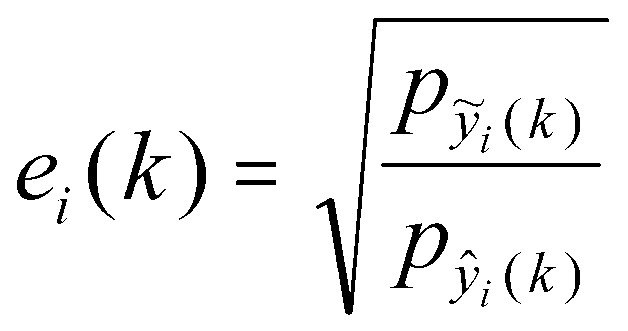
팩터 e(k)는 다음의 식(5)에 의해 구해진다:The factor e (k) is obtained by the following equation (5):

여기서, ![]()
![]()
![]()
![]()
![]()
![]()
![]()
![]()
일반적 BCC 합성General BCC Synthesis
도 4는 BCC 시스템(200)의 소정 실시예에 따라, 도 2의 디코더(204)로서 사용될 수 있는 BCC 합성기(400)의 블록 다이어그램을 나타낸다. BCC 합성기(400)는 각 전송 채널 yi(n)에 대해 마련된 필터 뱅크(402)와, 업믹싱 블록(404), 지연기(406), 승산기(408), 상관관계 블록(410), 그리고 각 재생 채널 ![]()
![]()
각 필터 뱅크(402)는 시간 영역에 있는 대응하는 디지털 전송 채널 yi(n)의 각 프레임을 주파수 영역에서 일단의 입력 계수 ![]()
![]()
![]()
![]()
![]()
![]()

여기서, ![]()
![]()
각 지연 수단(406)은 ICTD 데이터에 대한 대응하는 BCC 코드에 근거하여 지연 값 di(k)를 가함으로써 소망하는 ICTD 값이 재생 채널의 소정 쌍 사이에서 나타날 수 있게 한다. 각 승산기(408)는 ICLD 데이터에 대한 대응하는 BCC 코드에 근거하여 스케일링 팩터 ai(k)를 가함으로써 소망하는 ICLD 값이 재생 채널의 소정 쌍 사이에서 나타날 수 있게 한다. 상관관계 블록(410)은 ICC 데이터에 대한 대응하는 BCC 코드에 근거하여 상관관계 해제 동작을 수행함으로써 소망하는 ICC 값이 재생 채널의 소정 쌍 사이에서 나타날 수 있게 한다. 상관관계 블록(410)의 동작에 대한 부가적인 설명은 2002년 5월 24일자 미합중국 특허출원 제 10/155,437호에서 찾아볼 수 있다.Each delay means 406 applies a delay value d i (k) based on the corresponding BCC code for the ICTD data so that the desired ICTD value can appear between certain pairs of playback channels. Each
ICLD 합성은 단지 서브밴드 신호의 스케일링 동작을 포함하기 때문에, ICLD 값의 합성은 ICTD 및 ICC 값의 합성에 비해 덜 곤란하다. ICLD 큐는 가장 보편적으로 사용되는 방향성 큐이기 때문에 ICLD 값을 원시 오디오 신호의 ICLD 값에 근사하게 하는 것이 보다 중요하다. 이와 같이, ICLD 데이터는 모든 채널 쌍 사이에서 추정된다. 각 서브밴드에 대한 스케일링 팩터 ai(k)(1#i#C)는 바람직하게 각 재생 채널의 서브밴드 출력이 원시 입력 오디오채널의 대응하는 출력에 가까워지게 선택된다. Since ICLD synthesis only involves the scaling operation of the subband signal, synthesis of ICLD values is less difficult than synthesis of ICTD and ICC values. Since ICLD cues are the most commonly used directional cues, it is more important to approximate the ICLD value to the ICLD value of the raw audio signal. As such, ICLD data is estimated between all channel pairs. The scaling factor a i (k) (1 # i # C) for each subband is preferably chosen such that the subband output of each playback channel is close to the corresponding output of the original input audio channel.
ICTD 및 ICC 값을 합성하기 위해서는 상대적으로 신호에 대한 수정을 거의 가하지 않는다. 이와 같이, BCC 데이터는 모든 채널 쌍에 대한 ICTD 및 ICC 값을 포함하지 않는다. 여기서, BCC 합성기(400)는 소정의 채널 쌍 사이에서 ICTD 및 ICC 값만을 합성한다.In order to synthesize ICTD and ICC values, relatively few modifications are made to the signal. As such, BCC data does not include ICTD and ICC values for all channel pairs. Here, the
각각의 역 필터 뱅크(412)는 주파수 영역에 있는 대응하는 일단의 합성된 계수 ![]()
![]()
![]()
![]()
도 4에서, 후속하는 업믹싱 및 BCC 처리를 위해 모든 E개의 전송된 채널이 주파수 영역으로 변환되고 있음을 나타내고 있지만, 다른 실시에서는 하나 또는 그 이상의(전부는 아닌) E개 전송된 채널이 도 4에 나타낸 처리의 일부 또는 전부를 건너뛰게 할 수 있다. 예를 들어, 하나 또는 그 이상의 전송된 채널은 업믹싱 되지 않을 수정 안 된 채널로 될 수 있다. 하나 또는 그 이상의 C개 재생 채널로 되는 것에 부가하여, 그 수정되지 않은 채널은 강제적이지 않지만 하나 또는 그 이상의 다른 재생 채널을 합성하기 위해 BCC 처리가 적용되는 기준 채널로서 사용된다. 양 자의 어느 경우에도, 그와 같은 수정되지 않은 채널은, 나머지 재생 채널을 생성하는데 사용하는 업믹싱 및/또는 BCC 처리에 관련된 처리 시간을 보상하기 위해 지연될 수 있다. While FIG. 4 shows that all E transmitted channels are being converted to the frequency domain for subsequent upmixing and BCC processing, in another embodiment one or more (but not all) E transmitted channels are shown in FIG. 4. You can skip some or all of the processing shown in. For example, one or more transmitted channels may be unmodified channels that will not be upmixed. In addition to being one or more C playback channels, the unmodified channel is not mandatory but is used as a reference channel to which BCC processing is applied to synthesize one or more other playback channels. In either case, such an unmodified channel may be delayed to compensate for processing time related to upmixing and / or BCC processing used to generate the remaining playback channel.
도 4에서 C개의 재생 채널이(C는 또한 원시 입력 채널의 수) E개 전송된 채널로부터 합성되고 있음을 나타내고 있지만, BCC 합성은 그 재생 채널의 수에 제한받지 않는다. 일반적으로, 재생 채널의 수는 C보다 크거나 작은, 그리고 재생 채널의 수가 전송된 채널의 수와 동일하거나 작은 경우를 포함하는 어떤 수의 채널이라도 가능하다.4 shows that C playback channels (C is also the number of raw input channels) are being synthesized from the E transmitted channels, but BCC synthesis is not limited to the number of playback channels. In general, the number of playback channels can be any number of channels including greater or less than C, and the number of playback channels being equal to or less than the number of transmitted channels.
오디오채널 간의 "청각 관련 차이" "Hearing Differences" Between Audio Channels
단일의 합 신호를 가정할 때, BCC는 스테레오 또는 다채널 오디오신호를 ICTD, ICLD, 및 ICC가 원시 오디오신호의 대응하는 큐에 근사하게 되도록 합성한다. 이하에, 청각의 공간 이미지 속성에 관하여 ICTD, ICLD 및 ICC의 역할에 대해 논의한다. Assuming a single sum signal, the BCC synthesizes a stereo or multichannel audio signal such that the ICTD, ICLD, and ICC approximate a corresponding queue of raw audio signals. In the following, the role of ICTD, ICLD and ICC in relation to the spatial image attribute of hearing is discussed.
공간 청력에 대한 인식은 하나의 청각 이벤트에 대해, ICTD 및 ICLD가 지각 방향에 관계하고 있음을 의미한다. 하나의 음원의 바이노럴 룸 임펄스 응답(BRIR)을 고려할 때, BRIR의 초기 및 후기 부분을 추정하면 청각 이벤트의 폭과 청취자 싸개(envelopment)와 ICC 데이터 사이에 관계가 존재한다. 그러나, ICC와 일반 신호에 대한 이들 특성(BRIR 뿐만 아니라) 사이의 관계는 간단하지 않다.Perception of spatial hearing means that for one auditory event, the ICTD and ICLD are related to the perceptual direction. Given the binaural room impulse response (BRIR) of one sound source, there is a relationship between the width of the auditory event and the listener envelope and the ICC data when estimating the early and late parts of the BRIR. However, the relationship between these characteristics (as well as BRIR) for ICC and general signals is not simple.
스테레오 및 다채널 오디오신호는 통상 둘러싸인 공간에서 녹음하는 것에 기 인한 반사 신호 성분에 의해 중첩되거나, 공간적 느낌을 인공적으로 만들어내기 위해 녹음 기술자에 의해 가해진 동시 작용 원시 신호의 복합적 믹싱 녹음을 포함한다. 서로 다른 원시 신호 및 그들의 반사 신호는 시간-주파수 평면에서 서로 다른 영역을 점유한다. 이것은 시간 및 주파수의 함수로 변화하는 ICTD, ICLD, 및 ICC에 반영된다. 이 경우, 순간의 ICTD, ICLD, 및 ICC와 청각 이벤트의 방향, 그리고 공간적 느낌 사이의 관계는 분명하지 않다. BCC의 소정의 실시 예에서는 그들의 큐가 원시 오디오 신호의 대응하는 큐에 근접하게 되도록 큐들을 눈에 보이지 않게 합성한다.Stereo and multichannel audio signals typically include multiple mixed recordings of simultaneous raw signals, superimposed by reflected signal components due to recording in enclosed spaces, or applied by recording technicians to artificially create a spatial feel. Different raw signals and their reflected signals occupy different regions in the time-frequency plane. This is reflected in ICTD, ICLD, and ICC changing as a function of time and frequency. In this case, the relationship between the instant ICTD, ICLD, and the direction of the ICC and auditory event, and the spatial feeling is not clear. Some embodiments of BCC synthesize cues invisibly such that their cues are close to the corresponding cues of the raw audio signal.
등가 직각 대역폭(EBR)의 2배와 동등한 서브밴드 밴드폭을 가진 필터뱅크가 사용된다. 평상적인 청취에서, 높은 주파수 해상도를 선택했을 때 BCC의 오디오 품질은 현저하게 개선되지 않는다는 것이 알려졌다. 낮은 주파수 해상도를 사용하는 것이 디코더로 전송될 필요가 있는 ICTD, ICLD, 및 ICC 값을 적게 하고 따라서 낮은 비트율을 가질 수 있기 때문에 바람직하다. A filterbank with a subband bandwidth equal to twice the equivalent rectangular bandwidth (EBR) is used. In normal listening, it has been found that the audio quality of BCC is not significantly improved when high frequency resolution is selected. Using a lower frequency resolution is desirable because it reduces the ICTD, ICLD, and ICC values that need to be sent to the decoder and therefore can have a lower bit rate.
시간 해상도에 관하여, ICTD, ICLD, 및 ICC는 통상 일정한 시간 간격마다 고찰된다. ICTD, ICLD, 및 ICC가 약 4 내지 16 ms 마다 고찰될 때 높은 성능이 얻어진다. 큐가 매우 짧은 시간 간격으로 고찰되지 않는 경우, 선행 효과가 직접 고찰되지 않는다는 점을 주목해야 한다. 소리 자극의 전형적인 리드-래그(lead-lag) 쌍을 고려할 때, 이 리드-래그가 단 하나의 큐 세트가 합성되는 시간 간격에 떨어질 경우, 리드의 국소화 지배는 고려되지 않는다. 이에 불구하고, BCC는 평균 약 87 그리고 소정의 오디오 신호에 대해 거의 100에 가까운 MUSHRA 율 점수를 나타내는 오디오 품질(즉, "우수한" 오디오 품질)을 성취한다. With regard to time resolution, ICTD, ICLD, and ICC are usually considered at regular time intervals. High performance is obtained when ICTD, ICLD, and ICC are considered about every 4 to 16 ms. Note that if the queue is not considered at very short time intervals, the preceding effects are not directly considered. Considering typical lead-lag pairs of sound stimuli, if this lead-lag falls in the time interval at which only one cue set is synthesized, the localization domination of leads is not taken into account. In spite of this, the BCC achieves an average audio quality (ie, "excellent" audio quality) that represents a MUSHRA rate score of about 87 and nearly 100 for a given audio signal.
가끔 얻어지는 기준 신호와 합성 신호 간의 청각적으로 작은 차이는, 광범위한 청각 공간 이미지 속성에 관련한 큐가 일정 시간 간격마다 ICTD, ICLD, 및 ICC를 합성하는 것에 의해 암암리에 고찰되고 있다는 것을 의미한다. 다음에, 어떻게 ICTD, ICLD, 및 ICC가 청각 공간 이미지 속성의 일정 범위에 관련될 수 있는지에 대해 논의한다.An audibly small difference between the reference signal and the synthesized signal that is sometimes obtained implies that the cues associated with the wide range of auditory spatial image attributes are implicitly considered by synthesizing ICTD, ICLD, and ICC at regular time intervals. Next, how ICTD, ICLD, and ICC can be related to a range of auditory spatial image attributes is discussed.
공간 큐의 추정Estimation of Spatial Queues
이하, 어떻게 ICTD, ICLD, 및 ICC가 추정되는지에 대해 설명한다. (양자화 및 부호화된) 공간 큐를 전송하는데 필요한 비트율은 단지 수 kb/s으로 될 수 있으며, 따라서, BCC에 의해, 스테레오 및 다채널 오디오신호를 단일 오디오채널의 전송에 필요한 비트율에 근접한 비트율로 전송할 수 있다. The following describes how ICTD, ICLD, and ICC are estimated. The bitrate required to transmit the (quantized and coded) spatial queue can be only a few kb / s, so that, by the BCC, stereo and multichannel audio signals are transmitted at a bitrate close to that required for the transmission of a single audio channel. Can be.
도 5는 본 발명의 실시예에 따라 도 2의 BCC 추정기(208)의 상세 블록 다이어그램을 나타낸다. BCC 추정기(208)는 도 3의 필터뱅크(302)와 동일 형식으로 될 수 있는 필터뱅크(FB: 502)와, 이 필터뱅크(502)에서 생성된 각 서로 다른 주파수 서브밴드에 대한 ICTD, ICLD, 및 ICC의 공간 큐를 발생하는 추정 블록(504)을 포함한다.5 shows a detailed block diagram of the
스테레오 신호에 대한 ICTD, ICLD, 및 ICC 추정ICTD, ICLD, and ICC Estimation for Stereo Signals
다음의 해법은 2개(즉, 스테레오) 오디오채널의 대응하는 서브밴드 신호 ![]()
![]()
![]()
![]()
o ICTD [샘플]:o ICTD [sample]:
![]()
![]()
정규화된 상호 상관관계 함수에 대한 단시간 추정값은 다음의 식(8)에 의해 구해진다:The short time estimate for the normalized cross correlation function is obtained by the following equation (8):

여기서, here,
![]()
![]()
그리고 ![]()
![]()
![]()
![]()
o ICLD [dB]:o ICLD [dB]:

o ICC:o ICC:
![]()
![]()
여기서, 정규화된 상호 상관관계의 절대값이 고찰되었으며 c12(k)는 [0,1]의 범위를 갖는다.Here, the absolute value of normalized cross correlation is considered and c 12 (k) has a range of [0,1].
다채널 오디오 신호에 대한 ICTD, ICLD, 및 ICC 추정ICTD, ICLD, and ICC Estimation for Multichannel Audio Signals
2개 이상의 입력 채널이 존재할 때, C= 5인 채널에 대해 도 6에서 나타낸 것 과 같이, 기준 채널(예를 들어, 채널 번호 1)과 다른 채널 사이의 ICTD 및 ICLD를 충분히 정의할 수 있다. 여기서, τ1c(k) 및 ΔL12(k)는 각각 기준 채널 1과 채널 c 사이의 ICTD 및 ICLD를 지칭한다. When two or more input channels are present, the ICTD and ICLD between the reference channel (eg, channel number 1) and the other channel can be sufficiently defined, as shown in FIG. 6 for a channel with C = 5. Here, τ 1c (k) and ΔL 12 (k) refer to ICTD and ICLD between
ICTD 및 ICLD에 반하여, ICC는 통상 더 많은 자유도를 가진다. 정의된 ICC는 모든 입력 채널 쌍 사이에서 서로 다른 값을 가질 수 있다. C개 채널에 대해, 예를 들어, 5개 채널에 대해 도 7A에 나타낸 10개 채널 쌍과 같은, C(C-1)/2 개의 가능한 채널 쌍이 존재한다. 그러나, 이와 같은 방법은 각 시간 지수에서 각 서브채널에 대해 C(C-1)/2 개에 대한 ICC 값이 추정되고 전송되어야할 필요가 있으며, 이에 따라 높은 계산상 복잡성과 높은 비트율을 가져오게 된다.In contrast to ICTD and ICLD, ICC usually has more degrees of freedom. The defined ICC can have different values between all input channel pairs. For C channels, there are C ( C- 1) / 2 possible channel pairs, such as the 10 channel pairs shown in FIG. 7A for 5 channels. However, this method requires that the ICC values for C ( C -1) / 2 for each subchannel at each time index need to be estimated and transmitted, resulting in high computational complexity and high bit rate. do.
대안적으로, 각 서브밴드에 대해, ICTD 및 ICLD는 서브밴드에서 대응하는 신호 성분의 청각적 이벤트가 주어지는 방향을 결정한다. 서브밴드당 단일의 ICC 파라미터가 모든 오디오채널 사이의 전체 긴밀도를 표현하는데 사용될 수 있다. 각 시간 지수에서 대부분의 에너지가 각 서브밴드에 나타나게 하면서 단지 2개 채널 사이의 ICC 큐를 추정 및 전송하는 것에 의해 좋은 결과를 얻을 수 있다. 이 방법은 도 7(B)에 나타내었으며, 여기서 시간 순간 k-1 및 k에 대해 각각 채널 쌍 (3, 4)와 (1, 2)가 가장 강하다. 발견적 법칙이 다른 채널 쌍 사이의 ICC를 결정하는데 사용될 수 있다.Alternatively, for each subband, ICTD and ICLD determine the direction in which the auditory event of the corresponding signal component is given in the subband. A single ICC parameter per subband can be used to represent the overall long density between all audio channels. Good results can be obtained by estimating and transmitting an ICC queue between only two channels, with most energy in each subband at each time index. This method is shown in Fig. 7 (B), where channel pairs (3, 4) and (1, 2) are the strongest for k-1 and k, respectively, at time instants. Heuristic laws can be used to determine the ICC between different channel pairs.
공간 큐의 합성Synthesis of Spatial Queues
도 8은 도 4의 BCC 합성기(400)의 실시 예를 나타낸 블록 다이어그램으로, 이것은 단일의 전송된 합 신호 s(n)와 이에 부가된 공간 큐 신호가 주어진 스테레오 또는 다채널 오디오 신호를 생성하기 위한 BCC 디코더에서 사용될 수 있다. 합 신호 s(n)는 서브밴드로 분해되고, 여기서 ![]()
![]()
ICTD 합성ICTD synthesis
지연 dc 는 다음의 식 (12)에 의거하여, ICTD τ1c(k) 로부터 결정된다:Delay d c Is determined from ICTD τ 1c (k) based on the following equation (12):

기준 채널에 대한 지연 d1 은 지연 dc 의 최대 크기를 최소화시키는 것과 같이 하여 계산된다. 서브밴드 신호를 보다 적게 수정하면 인공음이 발생할 우려가 작아진다. 서브밴드 샘플링 비율이 ICTD 합성을 위해 충분히 높은 시간 해상도를 제공하지 않을 경우, 적절한 전역 통과 필터를 사용하여 지연을 더 정밀하게 가할 수 있다.The delay d 1 for the reference channel is calculated in such a way as to minimize the maximum magnitude of the delay d c . By modifying the subband signal less, there is less risk of artificial sound. If the subband sampling rate does not provide a sufficiently high time resolution for ICTD synthesis, an appropriate all-pass filter can be used to add more delay.
ICLD 합성ICLD Synthesis
출력 서브밴드 신호가 채널 c와 기준 채널 1 사이에서 소망의 ICLD ΔL12(k)를 갖게 하기 위하여, 이득 팩터 ac 는 다음과 같은 식 (13)을 만족하여야 한다:In order for the output subband signal to have the desired ICLD ΔL 12 (k) between channel c and
![]()
![]()
부가적으로, 출력 서브밴드는 바람직하게 모든 출력 채널의 출력(power) 합이 입력 합 신호의 출력(power)과 동일하게 되도록 정규화된다. 각 서브밴드에 있는 전체 원시 신호 출력이 합 신호에서 보존되고 있기 때문에, 이 정규화는 원시 인코더 입력 오디오 신호의 대응하는 출력에 근사하는, 각 출력 채널에 대한 절대 서브밴드 출력을 얻게 한다. 위와 같은 제한이 주어지면, 스케일 팩터 ac는 다음의 식 (14)에 의해 구해진다:In addition, the output subbands are preferably normalized such that the power sum of all output channels is equal to the power of the input sum signal. Since the total raw signal output in each subband is preserved in the sum signal, this normalization results in an absolute subband output for each output channel, approximating the corresponding output of the raw encoder input audio signal. Given the above limitations, the scale factor a c is obtained by the following equation (14):

ICCICC 합성 synthesis
소정의 실시예에서, ICC 합성의 목표는 지연 및 스케일링이 가해진 후, ICTD 및 ICLD에 영향을 주지 않고 서브밴드 간의 상관관계를 감소시키기 위한 것이다. 이 목적은 ICTD 및 ICLD가 주파수의 함수로서 효과적으로 변화되게 하고 그 평균 편차가 각 서브밴드(청각적으로 중요한 밴드)에서 영(0)이 되도록 도 8의 필터 hc 를 설계함으로써 이루어질 수 있다. In certain embodiments, the goal of ICC synthesis is to reduce the correlation between subbands without affecting ICTD and ICLD after delay and scaling have been applied. This object can be achieved by designing the filter h c of FIG. 8 so that the ICTD and ICLD are effectively changed as a function of frequency and the average deviation is zero in each subband (audially important band).
도 9는 ICTD 및 ICLD가 서브밴드 내에서 주파수의 함수로서 어떻게 변화하는 지를 보여준다. ICTD 및 ICLD 변화량의 진폭은 상관관계 감소 정도를 결정하며 그 진폭은 ICC의 함수로서 제어된다. 여기서, 도 9a에 나타낸 것과 같이 ICTD는 완만하게 변화되고, ICLD는 도 9b에 나타낸 것처럼 불규칙하게 변화된다. ICLD를 ICTD와 같이 완만하게 변화시킬 수 있지만, 이것은 생성된 오디오신호에 더 많은 상관관계를 주게 된다. 9 shows how ICTD and ICLD change as a function of frequency within a subband. The amplitude of the ICTD and ICLD changes determines the degree of correlation decrease and the amplitude is controlled as a function of ICC. Here, as shown in FIG. 9A, the ICTD changes slowly, and the ICLD changes irregularly as shown in FIG. 9B. ICLD can be changed gently like ICTD, but this gives more correlation to the generated audio signal.
특히 다채널 ICC 합성에 적합한 또 하나의 ICC 합성 방법은 논문, C. Faller, "Parametric multi-channel audio coding: Synthesis of coherence cues," IEEE Trans . on Speech and Audio Proc ., 2003 에 상세히 기재되어 있고 그 개시 내용은 본 명세서에 참고로 통합되었다. 시간 및 주파수의 함수로서, 소정 량의 인공 지연 잔향을 각 출력 채널에 가하여 원하는 ICC를 얻어낸다. 부가적으로, 결과 신호의 스펙트럼 엔벌로프가 원래 오디오신호의 스펙트럼 엔벌로프에 접근되게 하는 스펙트럼 수정이 가해질 수도 있다.Another ICC synthesis method that is particularly suitable for multichannel ICC synthesis is described in the paper, C. Faller, "Parametric multi-channel audio coding: Synthesis of coherence cues," IEEE Trans . on Speech and Audio Proc . , 2003, the disclosure of which is incorporated herein by reference. As a function of time and frequency, a predetermined amount of artificial delay reverberation is applied to each output channel to achieve the desired ICC. In addition, a spectral correction may be made that allows the spectral envelope of the resulting signal to approach the spectral envelope of the original audio signal.
스테레오 신호 (또는 오디오채널 쌍)에 관련 있는 다른 ICC 합성 기술은 논문, E. Schuijers, W. Oomen, B. den Brinker, and J. Breebaart, "Advances in parametric coding for high-quality audio," in Preprint 114 th Conv . Aud . Eng . Soc., Mar. 2003, 및 J. Engdegard, H. Purnhagen, J. Roden, and L. Liljeryd, "Synthetic ambience in parametric stereo coding," in Preprint 117 th Conv . Aud. Eng . Soc ., May 2004 에 발표되어 있으며, 이 2가지 논문의 개시 내용은 본 명세서에 참고로 통합되었다. Other ICC synthesis techniques related to stereo signals (or pairs of audio channels) are described in the paper, E. Schuijers, W. Oomen, B. den Brinker, and J. Breebaart, "Advances in parametric coding for high-quality audio," in Preprint. 114 th Conv . Aud . Eng . Soc. , Mar. 2003, and J. Engdegard, H. Purnhagen, J. Roden, and L. Liljeryd, "Synthetic ambience in parametric stereo coding," in Preprint 117 th Conv . Aud. Eng . Soc . , May 2004, the disclosures of both papers are incorporated herein by reference.
CC -- toto -- EE BCCBCC
전술한 바와 같이, BCC는 하나 이상의 전송 채널을 가지고 수행될 수 있다. BCC의 변화량은 하나의 단일 (전송) 채널이 아닌 E개 채널로서의 C개 오디오채널을 표현하는 것으로 설명되었다(C-to-E BCC 로 표시). C-to-E BCC에 대한 (적어도) 2개 요인이 존재한다:As mentioned above, BCC may be performed with one or more transport channels. The variation in BCC has been described as representing C audio channels as E channels rather than one single (transport) channel (indicated by C -to- E BCC). There are (at least) two factors for C -to- E BCC:
o 하나의 전송 채널에 대한 BCC는 스테레오 또는 다채널 오디오재생용의 기존 모노 시스템을 업그레이드하기 위한 하향 호환성 통로를 제공한다. 업그레이드된 시스템은 기존의 모노 장치를 통해 BCC 다운믹싱된 합 신호를 전송하는 한편 BCC 부수 정보를 부가적으로 전송한다. C-to-E BCC 는 C개 채널 오디오신호의 E개 채널 하향 호환성 코딩에 적용할 수 있다.o BCC on one transport channel provides a downward compatibility path for upgrading existing mono systems for stereo or multichannel audio playback. The upgraded system transmits the BCC downmixed sum signal through the existing mono device while additionally sending the BCC side information. C -to- E BCC can be applied to E-channel downlink coding of C-channel audio signals.
o C-to-E BCC 는 전송 채널 수 감소의 상이한 정도에 대한 조정가능성을 유도한다. 전송되는 오디오 채널이 많을수록 음성의 품질이 향상될 것으로 기대된다. o C -to- E BCC derives the adjustability for different degrees of transport channel number reduction. It is expected that the more audio channels are transmitted, the better the voice quality.
ICTD, ICLD, 및 ICC 큐를 정의하는 방법과 같은 C-to-E BCC의 신호 처리 과정들은 2004년 1월 20일자 미합중국 특허출원 제 10/762,100호 (대리인 명부 번호 Faller 13-1)에 설명되어 있다. Signal processing procedures for C -to- E BCCs, such as how to define ICTD, ICLD, and ICC queues, are described in US Patent Application No. 10 / 762,100 (Representative Directory No. Faller 13-1), dated January 20, 2004. have.
확산음Diffuse sound 정형 Orthopedic
소정의 실시예에서, BCC 코딩 방법은 ICTD, ICLD, 및/또는 ICC 합성을 위한 알고리즘을 포함한다. ICC 큐는 대응하는 서브밴드에서 신호 성분의 상관관계를 해제함으로써 합성될 수 있다. 이것은 ICLD의 주파수-의존 변화량, ICTD 및 ICLD의 주파수 의존 변화량, 올 패스 필터링, 또는 반향 알고리즘 관련 개념에 의해 수행될 수 있다.In certain embodiments, the BCC coding method comprises an algorithm for ICTD, ICLD, and / or ICC synthesis. ICC cues can be synthesized by uncorrelating new components in the corresponding subbands. This may be done by frequency-dependent variation of ICLD, frequency dependent variation of ICTD and ICLD, all-pass filtering, or echo algorithm related concepts.
이들 기술이 오디오신호에 적용될 때, 신호의 시간 엔벌로프 특성은 보존되지 않는다. 특히, 과도 신호에 적용될 때, 순간 신호 에너지는 소정 시간 간격 동안 발산된다. 이것은 "프리 에코" 또는 "퇴색한 과도 신호"와 같은 인공음으로 나타난다. When these techniques are applied to an audio signal, the temporal envelope characteristic of the signal is not preserved. In particular, when applied to transient signals, the instantaneous signal energy is dissipated for a predetermined time interval. This appears as an artificial sound, such as "pre echo" or "faded transient signal."
본 발명의 소정의 실시예에 있어서 일반적인 원리는 BCC 디코더에 의해 합성된 소리가 원래 소리의 스펙트럼 특성과 유사한 스펙트럼 특성을 가질 뿐만 아니라 유사한 청각 특성을 가지기 위해 원래 소리의 시간 엔벌로프에 매우 가깝게 닮는지를 관찰하는 것에 관련한다. 일반적으로, 이것은 각 신호 채널의 시간 엔벌로프를 접근시키기 위해 시간-변화 스케일링 연산을 적용하는 동적 ICLD 합성을 포함하는 유사 BCC 방법에 의해 달성된다. 그러나, 과도 신호(최초의 발음, 타악기 소리 등)에 대해, 위와 같은 처리의 시간 해상도는 원래 시간 엔벌로프에 가깝게 접근한 합성 신호를 생성하기에 충분치 않을 수 있다. 여기서는 충분하게 미세한 시간 해상도를 가지고 위의 처리를 수행하는 여러 가지 해결방법을 논의한다.In certain embodiments of the present invention, the general principle is that the sound synthesized by the BCC decoder not only has spectral characteristics similar to those of the original sound, but also closely resembles the temporal envelope of the original sound in order to have similar auditory characteristics. It relates to observation. In general, this is accomplished by a similar BCC method that includes dynamic ICLD synthesis that applies time-varying scaling operations to approach the temporal envelope of each signal channel. However, for transient signals (first pronunciation, percussion sounds, etc.), the temporal resolution of such processing may not be sufficient to produce a composite signal approaching the original temporal envelope. This article discusses several solutions for performing the above processing with sufficiently fine time resolution.
더욱이, 원래 신호의 시간 엔벌로프에 액세스하지 않은 BCC 디코더에 대해, 그 방법은 전송된 "합 신호(들)"의 시간 엔벌로프를 근삿값으로 대신 취하는 것이다. 이와 같이, 엔벌로프 정보를 전달하기 위해 BCC 인코더로부터 BCC 디코더로 전송되어야 할 부수 정보는 없다. 요약하면, 본 발명은 다음과 같은 원리에 기초한다:Moreover, for BCC decoders that do not have access to the temporal envelope of the original signal, the method instead takes an approximation of the temporal envelope of the transmitted "sum signal (s)". As such, there is no side information to be transmitted from the BCC encoder to the BCC decoder in order to convey the envelope information. In summary, the present invention is based on the following principle:
o 전송된 오디오채널들(즉, "합 채널") 또는 BCC 합성이 기반을 두게 될 이들 채널의 1차 조합은 시간 엔벌로프 추출기에 의해 높은 시간 해상도를 가지고(예를 들어, BCC 블록 크기보다 더 미세하게) 그 시간 엔벌로프에 대해 분석된다.o Transmitted audio channels (i.e., "sum channels") or first order combinations of these channels on which BCC synthesis will be based have a high temporal resolution by means of a temporal envelope extractor (e.g., larger than the BCC block size). Finely analyzed) for that time envelope.
o 각 출력 채널에 대해 후속의 합성된 소리가 ICC 합성 후에 추출기에 의해 결정된 시간 엔벌로프와 가능한 근접하여 정합되도록 정형된다. 이것은 과도 신호의 경우에 있어서도 그 합성된 출력 소리가 ICC 합성/신호 상관관계 해제 처리에 의해 질이 크게 저하되지 않게 한다.o For each output channel the subsequent synthesized sound is shaped to match as closely as possible to the time envelope determined by the extractor after ICC synthesis. This ensures that even in the case of a transient signal, the synthesized output sound is not greatly degraded by the ICC synthesis / signal correlation canceling process.
도 10은 본 발명의 하나의 실시예에 따른 BCC 디코더(1000)의 적어도 일부분을 나타내는 블록 다이어그램이다. 도 10에서, 블록 (1002)는 적어도 ICC 합성을 포함하는 BCC 합성 처리단을 나타낸다. BCC 합성 블록(1002)은 기준 채널(1001)을 수신하여 합성된 채널(1003)을 생성한다. 소정의 실시에서, 블록 (1002)는 도 4의 처리 블록(406),(408) 및 (410)을 대표한다. 여기서, 기준 채널(1001)은 업믹싱 블록(404)에 의해 생성된 신호이고, 합성된 채널(1003)은 상관관계 블록(410)에 의해 생성된 신호이다. 도 10은 하나의 기준 채널(1001')과 그 대응하는 합성 채널에 대 해 실시되는 처리를 나타낸다. 유사한 처리가 각각의 다른 기준 채널과 그 대응하는 합성 채널에 적용될 수 있다. 10 is a block diagram illustrating at least a portion of a
엔벌로프 추출기(1004)는 기준 채널(1001')의 미세 시간 엔벌로프 a를 결정하고, 엔벌로프 추출기(1006)는 합성된 채널(1003')의 미세 시간 엔벌로프 b를 결정한다. 역 엔벌로프 조정기(1008)는 엔벌로프 추출기(1006)에서 발생한 시간 엔벌로프 b를 사용하여 합성된 채널(1003')의 엔벌로프를 평균화(즉, 시간 미세 구조를 "평탄화")함으로써 평탄한(예를 들어, 균일한) 시간 엔벌로프를 가진 평탄화된 신호(1005')를 생성한다. 특정한 실시에 의하면, 평탄화는 업믹싱 이전 또는 이후에 적용될 수 있다. 엔벌로프 조정기(1010)는 엔벌로프 추출기(1004)에서 발생한 시간 엔벌로프 a를 사용하여 원래 시간 엔벌로프를 평탄화된 신호(1005')에 다시 부과하고, 이에 따라 기준 채널(1001)의 시간 엔벌로프와 실질적으로 동일한 시간 엔벌로프를 갖는 출력 신호(1007')를 생성한다.The
실시 예에 의하면, 위와 같은 시간 엔벌로프 처리(본 명세서에서 "엔벌로프 정형"이라고도 칭함)는 전체 합성 채널(도시된 것과 같은) 또는 합성된 채널(이후에 설명됨)의 직교화 부분(예를 들어, 지연 잔향 부분, 상관관계 해제 부분)에 대해서만 적용될 수 있다. 더욱이, 실시 예에 의하면, 엔벌로프 정형은 시간 영역 신호에 대해 또는 주파수 의존 방식(예를 들어, 시간 엔벌로프가 추정되고 서로 다른 주파수에 개별적으로 부과되는)으로 적용될 수 있다.According to an embodiment, such temporal envelope processing (also referred to herein as " envelope shaping ") may be performed by using an overall orthogonal portion of the synthesized channel (such as shown) or the synthesized channel (described later) (e.g., For example, it can be applied only to the delay reverberation part and the correlation cancel part. Moreover, according to an embodiment, envelope shaping may be applied to a time domain signal or in a frequency dependent manner (eg, a time envelope is estimated and separately imposed on different frequencies).
역 엔벌로프 조정기(1008) 및 엔벌로프 조정기(1010)는 상이한 방식으로 실시될 수 있다. 한가지 실시 예에서, 신호의 엔벌로프는 신호의 시간 영역 샘플들 (또는 스펙트럼/서브밴드 샘플)을 시간 변화 진폭 수정 함수(예를 들어, 역 엔벌로프 조정기(1008)에 대해 1/b 그리고 엔벌로프 조정기(1010)에 대해 a)를 가지고 곱셈하는 것에 의해 처리된다. 대안적으로, 주파수에 대해 신호의 스펙트럼 표현을 콘볼루션/필터링하는 것은 낮은 비트율의 오디오 코더의 양자화 잡음을 정형할 목적으로 종래기술에서 사용한 방법과 유사한 방법을 사용할 수 있다. 유사하게, 신호의 시간 엔벌로프가 신호의 시간 구조를 분석하는 것에 의해 직접적으로 또는 주파수에 대한 신호 스펙트럼의 자기상관관계를 검사하는 것에 의해 추출된다. Inverse envelope adjuster 1008 and
도 11은 도 4의 BCC 합성기(400)에 관련하여 도 10의 엔벌로프 정형 방법에 대한 적용 예를 나타낸다. 이 실시예에서, 단일의 전송된 합 신호 s(n)가 존재하고, C 기준 신호는 합 신호를 복제하는 것에 의해 생성되며, 엔벌로프 정형이 서로 다른 채널에 개별적으로 가해진다. 다른 실시예에서는 지연, 스케일링, 및 다른 처리의 순서를 달리할 수 있다. 더욱이, 이 다른 실시예에서, 엔벌로프 정형은 각 서브밴드를 독립적으로 처리하는 것에 제한되지 않는다. 이것은 특히 콘볼루션/필터링 기반 실시예가 주파수 밴드 전체의 긴밀성을 이용하여 신호의 시간적 미세 구조를 틀림없이 유도하게 한다.FIG. 11 illustrates an application example to the envelope shaping method of FIG. 10 in relation to the
도 11(A)에서, 시간 처리 분석기(TPA: 1104)는 도 10의 엔벌로프 추출기(1004)와 유사하며, 각 시간 처리기(TP: 1106)는 엔벌로프 추출기(1006), 역 엔벌로프 조정기(1008), 및 도 10의 엔벌로프 조정기(1010)의 조합과 유사하다. In FIG. 11 (A), the time processing analyzer (TPA) 1104 is similar to the
도 11(B)는 TPA(1104)의 하나의 가능한 시간 영역 기반 실시 예의 블록 다이어그램을 나타낸 것으로, 기준 신호 샘플들은 제곱되고(1110) 나서 저역 통과 필터 링(1112)되어 기준 신호의 시간 엔벌로프 a를 특징 지운다.FIG. 11B shows a block diagram of one possible time domain based embodiment of the
도 11(C)는 TP(1106)에 대한 하나의 가능한 시간 영역 기반 실시예의 블록 다이어그램을 나타낸 것으로, 합성된 신호 샘플이 제곱되고(1114), 저역 통과 필터링 되어(1116) 합성된 신호의 시간 엔벌로프 b를 특징 지운다. 스케일 팩터(예를 들어, a/b의 제곱근)가 생성(1118)된 다음 합성된 신호로 가해져서(1120) 원래 기준 채널의 시간 엔벌로프와 실질적으로 동일한 시간 엔벌로프를 갖는 출력 신호를 생성한다.11 (C) shows a block diagram of one possible time domain based embodiment for
TPA(1104) 및 TP(1106)에 대한 다른 실시 예에서, 시간 엔벌로프는 신호 샘플을 제곱하기보다는 크기 연산을 이용하여 특징 지워진다. 그와 같은 실시 예에서, 제곱근 연산을 적용할 필요없이 스케일 팩터로서 a/b 비가 사용될 수 있다.In other embodiments for
도 11(c)의 스케일링 동작이 TP 처리의 시간 영역 기반 실시에 해당한다 할지라도, TP 처리(TPA 및 역 TP(ITP)처리도 마찬가지)는 도 17-18의 실시예 (이후에 설명함)에서와 같이 주파수 영역 신호를 사용하여 실시될 수도 있다. 그와 같이, 본 명세서에서 용어 "스케일링 함수"는 도 18(B) 및 도 18(C)의 필터링 동작과 같은 시간 영역 또는 주파수 영역 연산 모두에 적용되는 것으로 해석되어야 한다.Although the scaling operation of FIG. 11 (c) corresponds to a time domain based implementation of TP processing, the TP processing (as well as TPA and reverse TP (ITP) processing) is the embodiment of FIGS. 17-18 (to be described later). As may be implemented using a frequency domain signal. As such, the term "scaling function" herein should be interpreted to apply to both time domain or frequency domain operations, such as the filtering operations of FIGS. 18B and 18C.
일반적으로, TPA(1104) 및 TP(1106)는 바람직하게 신호 출력 (즉, 에너지)를 수정하지 않도록 설계된다. 특정한 실시에 의하면, 이 신호 출력은 예를 들어 합성 윈도우에 의해 정의된 기간에서의 채널당 전체 신호 출력 또는 다른 적당한 출력 측정 방법에 기반하여 각 채널에서의 단시간 평균 신호 출력으로 구성될 수 있다. 이와 같이, ICLD 합성을 위한 스케일링은 (예를 들어, 승산기(408)을 사용한) 엔벌 로프 정형 이전 또는 이후에 적용될 수 있다.In general,
도 11(A)에서, 각 채널에 대해 2개의 출력이 존재하고, 여기서 TP 처리가 그 중 하나에 대해서만 적용된다. 이것은 2개 신호 성분, 즉 수정되지 않은 신호와 직교 신호를 혼합하는 ICC 합성 방법을 반영한다. 여기서, 수정되지 않은 신호와 직교 신호 성분의 비가 ICC를 결정한다. 도 11(A)에 나타낸 실시예에서, TP는 단지 직교 신호 성분에 대해 적용되며, 합 노드(1108)는 수정되지 않은 신호 성분을 대응하는 임시로 정형된 직교 신호 성분과 재결합시킨다.In Fig. 11A, there are two outputs for each channel, where TP processing is applied to only one of them. This reflects an ICC synthesis method that mixes two signal components, an unmodified signal and an orthogonal signal. Here, the ratio of the unmodified signal and the orthogonal signal component determines the ICC. In the embodiment shown in FIG. 11 (A), TP is only applied for orthogonal signal components, and
도 12는 도 4의 BCC 합성기(400)에 관련하여 도 10의 엔벌로프 정형 방법에 대한 다른 적용 예를 나타낸 것으로서, 엔벌로프 정형은 시간 영역에 적용된다. 이와 같은 실시예는 ICTD, ICLD, 및 ICC 합성이 수행되는 스펙트럼 표현의 시간 해상도가, 소망의 시간 엔벌로프를 부과하여 "프리 에코"를 효과적으로 방지하기에 충분히 높지 않을 때 용납될 수 있다. 예를 들어, 이것은 BCC 방법이 단시간 푸리에 변환(STFT)을 사용하여 실시되는 경우에 해당한다.FIG. 12 illustrates another application example of the envelope shaping method of FIG. 10 in relation to the
도 12(A)에 나타낸 것과 같이, TPA(1204) 및 TP(1206)는 시간 영역에서 실시되고, 전체 밴드 신호가 소망의 시간 엔벌로프를 갖도록(예를 들어, 전송된 합 신호로부터 추정된 것과 같은 엔벌로프) 그 밴드 신호가 크기조정된다. 도 12(B) 및 도 12(C)는 도 11(B) 및 도 11(C)에 나타낸 것과 유사한 TPA(1204) 및 TP(1206)의 가능한 실시예를 보여준다.As shown in FIG. 12A,
이 실시예에서, TP 처리는 직교 신호 성분뿐만 아니라 출력 신호에 적용된다. 대체 실시예에서, 시간 영역 기반의 TP 처리는 원하면 직교 신호 성분에만 적 용될 수 있으며, 이 경우 수정되지 않은 서브밴드와 직교 신호 서브밴드가 개별 역 필터 뱅크에 의해 시간 영역으로 변환된다.In this embodiment, the TP processing is applied to the output signal as well as the quadrature signal component. In an alternative embodiment, time domain based TP processing may be applied only to orthogonal signal components if desired, in which case the unmodified and orthogonal signal subbands are transformed into time domains by separate inverse filter banks.
BCC 출력 신호의 전체 밴드에 대한 크기조정이 인공음을 발생할 수 있기 때문에, 엔벌로프 정형은 특정 주파수, 예를 들어 소정의 차단 주파수 fTP (예를 들어, 500 Hz) 보다 높은 주파수에 대해서만 적용된다. TPA 분석을 위한 주파수 범위는 TP 합성을 위한 주파수 범위와는 다르다는 점을 주목하여야 한다.Because scaling over the entire band of the BCC output signal can produce artificial sounds, envelope shaping is only applied for certain frequencies, for example, frequencies above a certain cutoff frequency f TP (eg 500 Hz). . It should be noted that the frequency range for TPA analysis is different from the frequency range for TP synthesis.
도 13(A) 및 도 13(B)는 엔벌로프 정형이 차단 주파수 fTP 보다 높은 주파수에만 적용되는 TPA(1204) 및 TP(1206)의 가능한 실시예를 나타낸다. 특히, 도 13(A)는 시간 엔벌로프 특징화 이전에 차단 주파수 fTP 보다 낮은 주파수를 걸러내기 위한 고역 통과 필터(1302)를 추가로 구성한 것을 나타낸다. 도 13(B)는 2개의 서브밴드 사이에서 차단 주파수 fTP 를 갖는 2-밴드 필터뱅크(1304)가 추가되어 있는 것을 나타내며, 여기서 단지 높은 주파수 부분만이 임시로 정형된다. 이후 2-밴드 역 필터뱅크(1306)는 낮은 주파수 부분을, 임시로 정형된 높은 주파수 부분과 재결합시켜 출력 신호를 생성한다.13 (A) and 13 (B) show the envelope shaping frequency f TP A possible embodiment of the
도 14는 2004년 4월 1일자 미합중국 특허출원 제 10/815,591호 (대리인 명부 번호 Baumgarte 7-12)에 설명되어 있는 지연 잔향 기반 ICC 합성 방법에 관련하여 도 10의 엔벌로프 정형 방법의 적용 예를 나타낸다. 이 실시예에서, TPA(1404) 및 각 TP(1406)는 도 12 또는 도 13에서와 같이 시간 영역에서 적용되지만, 각 TP(1406)는 서로 다른 지연 잔향(LR) 블록(1402)으로부터의 출력에 적용된다.FIG. 14 shows an example of application of the envelope shaping method of FIG. 10 with respect to the delay reverberation based ICC synthesis method described in US patent application Ser. No. 10 / 815,591 dated April 1, 2004 (Agent No. Baumgarte 7-12). Indicates. In this embodiment, the
도 15는 도 10에 나타낸 방법에 대체될 수 있는 본 발명의 하나의 실시예에 따른 BCC 디코더(1500)의 적어도 일부를 나타내는 블록 다이어그램이다. 도 15에서, BCC 합성 블록(1502), 엔벌로프 추출기(1504), 및 엔벌로프 조정기(1510)는 도 10의 BCC 합성 블록(1002), 엔벌로프 추출기(1004), 및 엔벌로프 조정기(1010)와 유사하다. 그러나, 도 15에서, 역 엔벌로프 조정기(1508)가 도 10에서와 같이 BCC 합성 후 보다는 BCC 합성 이전에 가해진다. 이와 같이, 역 엔벌로프 조정기(1508)는 BCC 합성이 가해지기 이전에 기준 채널을 평탄화한다.FIG. 15 is a block diagram illustrating at least a portion of a
도 16은 도 10 및 도 15에 나타낸 방법에 대체될 수 있는 본 발명의 하나의 실시예에 따른 BCC 디코더(1600)의 적어도 일부를 나타내는 블록 다이어그램이다. 도 16에서, 엔벌로프 추출기(1604), 및 엔벌로프 조정기(1610)는 도 15의 엔벌로프 추출기(1504), 및 엔벌로프 조정기(1510)와 유사하다. 그러나, 도 15의 실시예에서, 합성 블록(1602)은 도 16에 나타낸 것과 유사한 지연 잔향 기반 ICC 합성을 의미한다. 이 경우, 엔벌로프 정형은 단지 상관관계되지 않은 지연 잔향 신호에 대해서만 적용되고, 합 노드(1612)는 임시 정형된 지연 잔향 신호를 원래 기준 채널(이미 소망의 시간 엔벌로프를 가짐)에 가한다. 이 경우, 지연 잔향 신호가 합성 블록 (1602)에서 그 생성 과정에 기인하여 대략 평탄한 시간 엔벌로프를 가지기 때문에 역 엔벌로프 조정기는 부가될 필요가 없다. FIG. 16 is a block diagram illustrating at least a portion of a
도 17은 도 4의 BCC 합성기(400)에 관련하여 도 15의 엔벌로프 정형 방법이 적용되는 예를 나타내는 도면이다. 도 17에서, TPA(1704), 역 TP(ITP: 1708), 및 TP(1710)는 도 15의 엔벌로프 추출기(1504), 역 엔벌로프 조정기(1508), 및 엔벌로 프 조정기(1510)와 유사하다. FIG. 17 is a diagram illustrating an example in which the envelope shaping method of FIG. 15 is applied to the
이와 같은 주파수 기반 실시예에서, 확산음의 엔벌로프 정형은 주파수 축을 따라 필터뱅크(402)의 주파수 상자(예를 들어, STFT)로 콘볼루션을 가하는 것에 의해 실시된다. 이에 대한 참고는 미합중국 특허 제 5,781,888호(Herre) 및 미합중국 특허 제 5,812,971호(Herre)를 들 수 있으며, 그 개시 내용은 본 명세서에 참고로 이 기술에 관련한 주제에 대해 통합되었다.In such frequency-based embodiments, envelope shaping of spreading is performed by convolution along a frequency axis into a frequency box (eg, STFT) of
도 18(A)는 도 17의 TPA(1704)의 하나의 가능한 실시예에 대한 블록 다이어그램을 나타낸다. 이 실시 예에서, TPA(1704)는 주파수에 대한 일련의 스펙트럼 계수에 대한 최적의 예측 계수를 결정하는 선형 예측 코딩(LPC) 분석 동작에 의해 수행된다. 이와 같은 LPC 분석 기법은 예를 들어 스피치 코딩과 같은 것으로부터 잘 알려져 있으며, LPC 계수를 효율적으로 계산하기 위한 많은 알고리즘이 자기상관관계법(신호의 자기상관관계 함수 및 후속 레빈슨-더빈 회귀의 계산을 포함)과 같은 것으로부터 알려져 있다. 그 계산 결과, 신호의 시간 엔벌로프를 나타내는 출력에서 일단의 LPC 계수를 구할 수 있다. 18A shows a block diagram of one possible embodiment of the
도 18(B) 및 (C)는 도 17의 ITP(1708) 및 TP(1710)의 가능한 실시 예를 나타낸 블록 다이어그램이다. 양 실시 예에서, 처리될 신호의 스펙트럼 계수는 도면에서 회전하는 스위치 회로로 표현한 것처럼 주파수 순서대로(증가 또는 감소) 처리되고, 이들 계수를 예측 필터링 처리에 의한 처리를 위해 순차로 변환한다(그리고 이 처리 후 다시 돌아간다). ITP(1708)의 경우, 예측 필터링은 예측 오차를 계산하고 이러한 방식으로 시간 신호 엔벌로프를 "평탄화"한다. TP(1710)의 경우, 역 필 터는 TPA(1704)로부터의 LPC 계수에 의해 표현된 시간 엔벌로프를 재도입한다.18B and 18C are block diagrams illustrating possible embodiments of the
TPA(1704)에 의한 신호의 시간 엔벌로프 계산을 위해, 필터뱅크(402)의 분석 윈도우의 영향을 제거하는 것이 중요하다 (그와 같은 분석 윈도우가 사용될 경우). 이것은 (알려진) 분석 윈도우 정형에 의해 결과 엔벌로프를 평균화하는 것에 의해 또는 분석 윈도우를 채용하지 않은 개별 분석 필터뱅크를 사용하는 것에 의해 달성될 수 있다.For calculating the time envelope of the signal by the
도 17의 콘볼루션/필터링 기반 기법은 도 16의 엔벌로프 정형 방법에 관련하여 적용될 수 있으며, 여기서 엔벌로프 추출기(1604) 및 엔벌로프 조정기(1610)는 도 18(A)의 TPA 및 도 18(C)의 TP 각각에 기반을 둔다.The convolution / filtering based technique of FIG. 17 can be applied in relation to the envelope shaping method of FIG. 16, where the
부가적인 대체 Additional substitution 실시예Example
BCC 디코더는 엔벌로프 정형을 선택적으로 인에이블링/디스에이블링하게 설계될 수 있다. 예를 들어, BCC 디코더는 통상의 BCC 합성 방법을 적용하여, 합성된 신호의 시간 엔벌로프가 충분히 동요할 때 엔벌로프 정형을 인에이블시킴으로써 엔벌로프 정형의 이득이 엔벌로프 정형을 수행할 어떤 인공음을 억누르게 한다. 이와 같은 인에이블링/디스에이블링 제어는 다음과 같은 처리에 의해 달성된다.The BCC decoder can be designed to selectively enable / disable envelope shaping. For example, the BCC decoder employs a conventional BCC synthesis method to enable envelope shaping when the temporal envelope of the synthesized signal is sufficiently fluctuated, so that the gain of the envelope shaping is any artificial sound that will perform the envelope shaping. To suppress Such enabling / disabling control is achieved by the following processing.
(1) 과도 신호 검출: 과도 신호가 검출된 경우, TP 처리가 인에이블된다. 과도 신호 검출은 예견 방식을 사용하여 단일의 과도 신호는 물론 이 과도 신호 바로 앞뒤의 신호 성분까지 유효하게 정형한다. 과도 신호 검출의 가능한 방법은 다음을 포함한다:(1) Transient signal detection: When a transient signal is detected, TP processing is enabled. Transient signal detection uses predictive methods to effectively shape a single transient signal as well as the signal components immediately before and after this transient signal. Possible methods of transient signal detection include:
o 전송된 BCC 합 신호(들)의 시간 엔벌로프를 관찰한다. 출력에 급격한 증가가 있을 경우, 과도 신호가 발생한 것으로 결정한다.o Observe the temporal envelope of the transmitted BCC sum signal (s). If there is a sudden increase in output, determine that a transient signal has occurred.
o 선형 예측 코딩(LPC) 필터의 이득을 검사한다. LPC 예측 이득이 소정의 임계값을 초과할 경우, 신호가 순간적이거나 크게 동요하는 것으로 추정될 수 있다. LPC 분석은 스펙트럼의 자기상관관계에 대해 계산된다.o Examine the gain of the LPC filter. If the LPC prediction gain exceeds a predetermined threshold, it can be assumed that the signal is instantaneous or highly shaken. LPC analysis is calculated for the autocorrelation of the spectrum.
(2) 무작위 검출: 시간 엔벌로프가 의사 무작위적으로(in a pseudo-random manner) 동요하는 경우를 상정할 수 있다. 이 경우, 아무런 과도 신호도 검출되지 않으며 다만 TP 처리만이 적용된다 (예를 들어, 고밀도의 박수 신호가 이 경우에 해당된다).(2) Random Detection: It can be assumed that the temporal envelope fluctuates in a pseudo-random manner. In this case, no transient signal is detected but only TP processing is applied (for example, a high density clap signal is applicable in this case).
부가적으로, 소정의 실시에서, 전송된 합 신호(들)의 음조가 높을 때 음조 신호에서 가능한 인공음을 방지하기 위해, TP 처리를 가하지 않는다.Additionally, in some implementations, no TP processing is applied to prevent possible artificial sounds in the tonal signal when the tonality of the transmitted sum signal (s) is high.
더욱이, 유사한 방법이 BCC 인코더에서 사용되어 TP 처리가 활성화되어야 할 시점을 검출할 수 있다. 인코더가 모든 원시 입력 신호에 액세스하기 때문에, 언제 TP 처리를 인에이블시킬 것인지 결정하기 위해 보다 복잡한 알고리즘(예를 들어, 추정 블록(208)의 일부)을 채택할 수 있다. 이 결정 결과(TP 처리가 활성화되어야 할 시점을 나타내는 플래그)는 BCC 디코더(예를 들어, 도 2의 부수 정보의 일부분으로서)로 전송될 수 있다.Moreover, a similar method can be used in the BCC encoder to detect when TP processing should be activated. Since the encoder has access to all raw input signals, more complex algorithms (eg, part of estimation block 208) may be employed to determine when to enable TP processing. This determination result (flag indicating when the TP processing should be activated) may be sent to a BCC decoder (eg, as part of the collateral information of FIG. 2).
본 발명이 단일의 합 신호를 사용하는 BCC 코딩 방법에 관련하여 설명되었지만, 본 발명은 2개 또는 그 이상의 합 신호를 갖는 BCC 코딩 방법에 관련하여 실시될 수도 있다. 이 경우, 각각의 서로 다른 "기준" 합 신호가 BCC 합성을 적용하기 전에 산출될 수 있으며, 어떤 합 신호가 서로 다른 출력 채널을 합성하는데 사용되 었는 가에 따라 서로 다른 시간 엔벌로프에 근거하여 서로 다른 BCC 출력 채널이 생성될 수 있다. 2개 또는 그 이상의 상이한 합 채널로부터 합성된 하나의 출력 채널은 구성하는 합 채널의 관련 효과를 고려하여(예를 들어, 가중 평균화) 하나의 유효한 시간 엔벌로프에 기반하여 생성될 수 있다.Although the present invention has been described with reference to a BCC coding method using a single sum signal, the present invention may be practiced with respect to a BCC coding method with two or more sum signals. In this case, each different "reference" sum signal can be calculated before applying BCC synthesis, and each other based on different time envelopes depending on which sum signal was used to synthesize different output channels. Other BCC output channels can be created. One output channel synthesized from two or more different sum channels may be generated based on one valid time envelope, taking into account the relevant effects of the constituting sum channels (eg, weighted averaging).
본 발명이 ICTD, ICLD, 및 ICC 코드를 포함하는 BCC 코딩 방법에 관련하여 설명되었지만, 본 발명은 그 3가지 코드 중 하나 또는 2개의 코드(예를 들어, ICTD는 제외하고 ICLD 및 ICC) 및/또는 하나 또는 그 이상의 부가적 형태의 코드들을 포함하는 다른 BCC 코딩 방법에 관련하여 실시될 수도 있다. 더욱이, BCC 합성 처리 순서와 엔벌로프 정형 순서가 서로 다른 실시에 따라 변화할 수 있다. 예를 들어, 엔벌로프 정형이 도 14 및 도 16에서와 같이 주파수 영역 신호에 적용되는 경우, 엔벌로프 정형은 ICTD 합성 후에(ICTD 합성을 채택한 실시예에서), 그리고 ICLD 합성 전에 선택적으로 실시될 수 있다. 다른 실시예에서, 엔벌로프 정형은 다른 어떤 BCC 합성이 적용되기 전에 업믹스 신호에 적용될 수 있다.Although the present invention has been described with reference to a BCC coding method comprising ICTD, ICLD, and ICC codes, the present invention is directed to one or two codes of the three codes (e.g., ICLD and ICC except ICTD) and / Or in connection with another BCC coding method comprising one or more additional types of codes. Moreover, the order of BCC synthesis processing and the order of envelope shaping may vary according to different implementations. For example, when envelope shaping is applied to a frequency domain signal as in FIGS. 14 and 16, envelope shaping may optionally be performed after ICTD synthesis (in embodiments employing ICTD synthesis) and before ICLD synthesis. have. In other embodiments, envelope shaping may be applied to the upmix signal before any other BCC synthesis is applied.
본 발명이 BCC 코딩 방법에 관련하여 설명되었지만, 본 발명은 오디오 신호가 상관관계를 갖지 않는 다른 오디오처리 시스템 또는 신호의 상관관계를 해제하는 것이 필요한 다른 오디오처리에 관련하여 실시될 수 있다. Although the present invention has been described with respect to a BCC coding method, the present invention may be practiced with respect to other audio processing systems in which the audio signal does not have correlation or other audio processing that needs to uncorrelate the signal.
본 발명이 인코더가 시간 영역에서 오디오 신호를 수신하고 시간 영역에서 전송 오디오 신호를 생성하는 실시예와, 디코더가 시간 영역에서 전송된 오디오 신 호를 수신하고 시간 영역에서 재생 오디오 신호를 생성하는 실시예에 관련하여 설명되었지만, 본 발명은 이에 국한되지 않는다. 예를 들어, 다른 실시예에서, 하나 또는 그 이상의 입력 신호, 전송 신호, 및 재생 오디오 신호가 주파수 영역에서 표현될 수 있다. The present invention is an embodiment in which an encoder receives an audio signal in the time domain and generates a transmission audio signal in the time domain, and an embodiment in which the decoder receives an audio signal transmitted in the time domain and generates a reproduction audio signal in the time domain. Although described in connection with, the present invention is not limited thereto. For example, in other embodiments, one or more input signals, transmission signals, and playback audio signals may be represented in the frequency domain.
BCC 인코더 및/또는 디코더는 텔레비전 또는 전자적 음악 배포, 영화관, 방송, 스트리밍 및/또는 수신을 위한 시스템을 포함하는 다양한 서로 다른 어플리케이션 또는 시스템과 조합하여 또는 일체로 사용될 수 있다. 이것은 예를 들어, 지상파, 위성, 케이블, 인터넷, 인트라넷, 또는 물리적 매체(예를 들어, 컴팩트 디스크, 디지털 다목적 디스크, 반도체 칩, 하드 드라이브, 메모리 카드, 등)를 통한 신호 전송을 인코딩/디코딩하는 시스템을 포함한다. BCC 인코더 및/또는 디코더는 예를 들어, 오락(액션, 롤 플레잉, 전략, 모험, 시뮬레이션, 경주, 스포츠, 아케이드, 카드, 및 보드 게임)을 위해 또는 다중 머신, 플랫포옴, 미디어용으로 발행되는 교육을 위해 사용자와 상호작용하게 만들어진 대화형 소프트웨어 제품을 포함하는 게임 및 게임 시스템에 채택될 수 있다. 더욱이, BCC 인코더 및/또는 디코더는 오디오녹음기/재생기 또는 CD-ROM/DVD 시스템에 통합될 수 있다. BCC 인코더 및/또는 디코더는 디지털 디코딩(예를 들어, 재생기, 디코더)을 포함하는 PC 소프트웨어 어플리케이션 및 디지털 인코딩 능력을 포함하는(예를 들어, 인코더, 리퍼, 리코더, 쥬크박스) 소프트웨어 어플리케이션에 통합될 수 있다.The BCC encoder and / or decoder may be used in combination or integrally with a variety of different applications or systems, including systems for television or electronic music distribution, cinemas, broadcasting, streaming and / or reception. This can be used to encode / decode signal transmission over, for example, terrestrial, satellite, cable, Internet, intranet, or physical media (eg, compact discs, digital general purpose discs, semiconductor chips, hard drives, memory cards, etc.). It includes a system. BCC encoders and / or decoders are, for example, educational publications for entertainment (action, role-playing, strategy, adventure, simulation, racing, sports, arcade, card, and board games) or for multiple machines, platforms, media Can be employed in games and game systems, including interactive software products made to interact with a user. Moreover, the BCC encoder and / or decoder can be integrated into an audio recorder / player or a CD-ROM / DVD system. The BCC encoder and / or decoder may be integrated into a PC software application including digital decoding (eg, player, decoder) and a software application including digital encoding capability (eg, encoder, ripper, recorder, jukebox). Can be.
본 발명은 단일 집적회로(ASIC 또는 FPGA와 같은), 다중 칩 모듈, 단일 카드 또는 다중 카드 회로 팩과 같은 있을 수 있는 구현을 포함하는 회로 기반 처리기로 실시될 수도 있다. 이 분야의 숙련된 기술자에게는 명백한 것이지만, 회로 구성 요소의 여러 가지 기능은 소프트웨어 프로그램에서 처리 단계로서 구현될 수 있다는 것이다. 그와 같은 소프트웨어는 예를 들어 디지털 신호 처리기, 마이크로 컨트롤러, 또는 범용 컴퓨터에서 채택될 수 있다. The invention may also be practiced with circuit-based processors that may include implementations such as single integrated circuits (such as ASICs or FPGAs), multiple chip modules, single cards, or multiple card circuit packs. As will be apparent to those skilled in the art, various functions of circuit components may be implemented as processing steps in a software program. Such software can be employed, for example, in digital signal processors, microcontrollers, or general purpose computers.
본 발명이 방법의 형태와 그 방법을 실시하는 장치의 형태를 가지고 구현될 수 있지만, 본 발명은 플로피 디스켓, CD-ROM, 하드 드라이브, 또는 어떤 다른 기계 판독 가능한 기억 매체와 같은 유형의 미디어 내에 구현된 프로그램 코드의 형태로 구현될 수 있다. 본 발명은 예를 들어 기억 매체에 저장되고 기계에 의해 로딩 및/또는 실행되거나, 전기적 선로 또는 케이블 망, 광 섬유, 또는 전자기적 방사를 통하는 것과 같은 소정의 전송 매체 또는 캐리어를 통해 전송된다. 여기서, 프로그램 코드가 컴퓨터와 같은 기계에 의해 로딩되고 실행될 때, 이 기계는 본 발명을 수행하는 장치로 된다. 범용 프로세서에서 구현될 경우, 프로그램 코드 세그먼트는 프로세서와 결합하여 특정 로직 회로와 유사하게 동작하는 독특한 장치를 제공할 수 있다.Although the present invention can be implemented in the form of a method and of a device implementing the method, the present invention is embodied in a type of media such as a floppy diskette, CD-ROM, hard drive, or any other machine readable storage medium. It can be implemented in the form of a program code. The invention is stored, for example, in a storage medium and loaded and / or executed by a machine, or transmitted via any transmission medium or carrier, such as via electrical lines or cable networks, optical fibers, or electromagnetic radiation. Here, when the program code is loaded and executed by a machine such as a computer, the machine becomes an apparatus for carrying out the present invention. When implemented in a general purpose processor, the program code segment may be combined with the processor to provide a unique device that operates similarly to a particular logic circuit.
본 발명의 본질을 설명하기 위해 도시하고 설명한 부분의 세부 사항과 재료, 배치에 대해 이 분야의 숙련된 사람에게는 이하의 청구범위에서 토로한 것과 같은 본 발명의 범위를 벗어나지 않고 다양한 변경이 이루어질 수 있다. Various changes may be made to those skilled in the art with respect to the details, materials, and arrangements of the parts shown and described to explain the nature of the invention, without departing from the scope of the invention as set forth in the claims below. .
이하의 방법 청구범위에서 처리 단계가 대응하는 부호와 함께 특정한 순서를 가지고 상술 되었지만, 청구범위의 기술 내용이 그 처리 단계의 전부 또는 일부를 실시하기 위한 특정 순서를 의미하고 있지 않은 이상, 그 처리 단계는 그 특정 순 서로 실시되는 것에 국한되지 않는다. In the following method claims, the processing steps have been described above in a specific order with corresponding signs, but unless the description in the claims implies a specific order for carrying out all or part of the processing steps, the processing steps Is not limited to being performed in that particular order.
Claims (34)
Applications Claiming Priority (4)
| Application Number | Priority Date | Filing Date | Title |
|---|---|---|---|
| US62040104P | 2004-10-20 | 2004-10-20 | |
| US60/620,401 | 2004-10-20 | ||
| US11/006,492 | 2004-12-07 | ||
| US11/006,492 US8204261B2 (en) | 2004-10-20 | 2004-12-07 | Diffuse sound shaping for BCC schemes and the like |
Publications (2)
| Publication Number | Publication Date |
|---|---|
| KR20070061882A KR20070061882A (en) | 2007-06-14 |
| KR100922419B1 true KR100922419B1 (en) | 2009-10-19 |
Family
ID=36181866
Family Applications (1)
| Application Number | Title | Priority Date | Filing Date |
|---|---|---|---|
| KR1020077008796A KR100922419B1 (en) | 2004-10-20 | 2005-09-12 | Diffuse sound envelope shaping for Binural Cue coding schemes and the like |
Country Status (20)
| Country | Link |
|---|---|
| US (2) | US8204261B2 (en) |
| EP (1) | EP1803325B1 (en) |
| JP (1) | JP4625084B2 (en) |
| KR (1) | KR100922419B1 (en) |
| CN (2) | CN101853660B (en) |
| AT (1) | ATE413792T1 (en) |
| AU (1) | AU2005299070B2 (en) |
| BR (1) | BRPI0516392B1 (en) |
| CA (1) | CA2583146C (en) |
| DE (1) | DE602005010894D1 (en) |
| ES (1) | ES2317297T3 (en) |
| HK (1) | HK1104412A1 (en) |
| IL (1) | IL182235A (en) |
| MX (1) | MX2007004725A (en) |
| NO (1) | NO339587B1 (en) |
| PL (1) | PL1803325T3 (en) |
| PT (1) | PT1803325E (en) |
| RU (1) | RU2384014C2 (en) |
| TW (1) | TWI330827B (en) |
| WO (1) | WO2006045373A1 (en) |
Families Citing this family (86)
| Publication number | Priority date | Publication date | Assignee | Title |
|---|---|---|---|---|
| US8260393B2 (en) | 2003-07-25 | 2012-09-04 | Dexcom, Inc. | Systems and methods for replacing signal data artifacts in a glucose sensor data stream |
| US8010174B2 (en) | 2003-08-22 | 2011-08-30 | Dexcom, Inc. | Systems and methods for replacing signal artifacts in a glucose sensor data stream |
| US20140121989A1 (en) | 2003-08-22 | 2014-05-01 | Dexcom, Inc. | Systems and methods for processing analyte sensor data |
| DE102004043521A1 (en) * | 2004-09-08 | 2006-03-23 | Fraunhofer-Gesellschaft zur Förderung der angewandten Forschung e.V. | Device and method for generating a multi-channel signal or a parameter data set |
| JPWO2006059567A1 (en) * | 2004-11-30 | 2008-06-05 | 松下電器産業株式会社 | Stereo encoding apparatus, stereo decoding apparatus, and methods thereof |
| EP1866911B1 (en) * | 2005-03-30 | 2010-06-09 | Koninklijke Philips Electronics N.V. | Scalable multi-channel audio coding |
| ATE421845T1 (en) * | 2005-04-15 | 2009-02-15 | Dolby Sweden Ab | TEMPORAL ENVELOPE SHAPING OF DECORRELATED SIGNALS |
| JP5452915B2 (en) * | 2005-05-26 | 2014-03-26 | エルジー エレクトロニクス インコーポレイティド | Audio signal encoding / decoding method and encoding / decoding device |
| MX2007015118A (en) * | 2005-06-03 | 2008-02-14 | Dolby Lab Licensing Corp | Apparatus and method for encoding audio signals with decoding instructions. |
| EP1908057B1 (en) * | 2005-06-30 | 2012-06-20 | LG Electronics Inc. | Method and apparatus for decoding an audio signal |
| JP5227794B2 (en) * | 2005-06-30 | 2013-07-03 | エルジー エレクトロニクス インコーポレイティド | Apparatus and method for encoding and decoding audio signals |
| EP1913577B1 (en) * | 2005-06-30 | 2021-05-05 | Lg Electronics Inc. | Apparatus for encoding an audio signal and method thereof |
| US7783494B2 (en) * | 2005-08-30 | 2010-08-24 | Lg Electronics Inc. | Time slot position coding |
| JP4568363B2 (en) * | 2005-08-30 | 2010-10-27 | エルジー エレクトロニクス インコーポレイティド | Audio signal decoding method and apparatus |
| US8577483B2 (en) * | 2005-08-30 | 2013-11-05 | Lg Electronics, Inc. | Method for decoding an audio signal |
| WO2007027055A1 (en) * | 2005-08-30 | 2007-03-08 | Lg Electronics Inc. | A method for decoding an audio signal |
| US7788107B2 (en) * | 2005-08-30 | 2010-08-31 | Lg Electronics Inc. | Method for decoding an audio signal |
| US8019614B2 (en) * | 2005-09-02 | 2011-09-13 | Panasonic Corporation | Energy shaping apparatus and energy shaping method |
| EP1761110A1 (en) | 2005-09-02 | 2007-03-07 | Ecole Polytechnique Fédérale de Lausanne | Method to generate multi-channel audio signals from stereo signals |
| EP1946297B1 (en) * | 2005-09-14 | 2017-03-08 | LG Electronics Inc. | Method and apparatus for decoding an audio signal |
| US7672379B2 (en) * | 2005-10-05 | 2010-03-02 | Lg Electronics Inc. | Audio signal processing, encoding, and decoding |
| US7751485B2 (en) * | 2005-10-05 | 2010-07-06 | Lg Electronics Inc. | Signal processing using pilot based coding |
| US7646319B2 (en) * | 2005-10-05 | 2010-01-12 | Lg Electronics Inc. | Method and apparatus for signal processing and encoding and decoding method, and apparatus therefor |
| KR100857111B1 (en) * | 2005-10-05 | 2008-09-08 | 엘지전자 주식회사 | Method and apparatus for signal processing and encoding and decoding method, and apparatus therefor |
| US7696907B2 (en) | 2005-10-05 | 2010-04-13 | Lg Electronics Inc. | Method and apparatus for signal processing and encoding and decoding method, and apparatus therefor |
| JP5329963B2 (en) * | 2005-10-05 | 2013-10-30 | エルジー エレクトロニクス インコーポレイティド | Signal processing method and apparatus, encoding and decoding method, and apparatus therefor |
| US7653533B2 (en) * | 2005-10-24 | 2010-01-26 | Lg Electronics Inc. | Removing time delays in signal paths |
| US20070133819A1 (en) * | 2005-12-12 | 2007-06-14 | Laurent Benaroya | Method for establishing the separation signals relating to sources based on a signal from the mix of those signals |
| KR100803212B1 (en) * | 2006-01-11 | 2008-02-14 | 삼성전자주식회사 | Method and apparatus for scalable channel decoding |
| US7752053B2 (en) * | 2006-01-13 | 2010-07-06 | Lg Electronics Inc. | Audio signal processing using pilot based coding |
| ES2335246T3 (en) * | 2006-03-13 | 2010-03-23 | France Telecom | SYNTHESIS AND JOINT SOUND SPECIALIZATION. |
| US20090299755A1 (en) * | 2006-03-20 | 2009-12-03 | France Telecom | Method for Post-Processing a Signal in an Audio Decoder |
| US8126152B2 (en) * | 2006-03-28 | 2012-02-28 | Telefonaktiebolaget L M Ericsson (Publ) | Method and arrangement for a decoder for multi-channel surround sound |
| ATE527833T1 (en) * | 2006-05-04 | 2011-10-15 | Lg Electronics Inc | IMPROVE STEREO AUDIO SIGNALS WITH REMIXING |
| US8379868B2 (en) * | 2006-05-17 | 2013-02-19 | Creative Technology Ltd | Spatial audio coding based on universal spatial cues |
| US7876904B2 (en) * | 2006-07-08 | 2011-01-25 | Nokia Corporation | Dynamic decoding of binaural audio signals |
| US20100040135A1 (en) * | 2006-09-29 | 2010-02-18 | Lg Electronics Inc. | Apparatus for processing mix signal and method thereof |
| BRPI0710923A2 (en) * | 2006-09-29 | 2011-05-31 | Lg Electronics Inc | methods and apparatus for encoding and decoding object-oriented audio signals |
| EP2084901B1 (en) | 2006-10-12 | 2015-12-09 | LG Electronics Inc. | Apparatus for processing a mix signal and method thereof |
| US7555354B2 (en) * | 2006-10-20 | 2009-06-30 | Creative Technology Ltd | Method and apparatus for spatial reformatting of multi-channel audio content |
| CN101536086B (en) * | 2006-11-15 | 2012-08-08 | Lg电子株式会社 | A method and an apparatus for decoding an audio signal |
| US8265941B2 (en) | 2006-12-07 | 2012-09-11 | Lg Electronics Inc. | Method and an apparatus for decoding an audio signal |
| EP2122612B1 (en) * | 2006-12-07 | 2018-08-15 | LG Electronics Inc. | A method and an apparatus for processing an audio signal |
| CN103137131A (en) * | 2006-12-27 | 2013-06-05 | 韩国电子通信研究院 | Code conversion apparatus for surrounding decoding of movement image expert group |
| US8463605B2 (en) * | 2007-01-05 | 2013-06-11 | Lg Electronics Inc. | Method and an apparatus for decoding an audio signal |
| FR2911426A1 (en) * | 2007-01-15 | 2008-07-18 | France Telecom | MODIFICATION OF A SPEECH SIGNAL |
| US20100121470A1 (en) * | 2007-02-13 | 2010-05-13 | Lg Electronics Inc. | Method and an apparatus for processing an audio signal |
| WO2008100067A1 (en) * | 2007-02-13 | 2008-08-21 | Lg Electronics Inc. | A method and an apparatus for processing an audio signal |
| ATE547786T1 (en) * | 2007-03-30 | 2012-03-15 | Panasonic Corp | CODING DEVICE AND CODING METHOD |
| US8548615B2 (en) * | 2007-11-27 | 2013-10-01 | Nokia Corporation | Encoder |
| EP2227804B1 (en) * | 2007-12-09 | 2017-10-25 | LG Electronics Inc. | A method and an apparatus for processing a signal |
| EP2254110B1 (en) * | 2008-03-19 | 2014-04-30 | Panasonic Corporation | Stereo signal encoding device, stereo signal decoding device and methods for them |
| KR101600352B1 (en) * | 2008-10-30 | 2016-03-07 | 삼성전자주식회사 | / method and apparatus for encoding/decoding multichannel signal |
| EP2377123B1 (en) * | 2008-12-19 | 2014-10-29 | Dolby International AB | Method and apparatus for applying reverb to a multi-channel audio signal using spatial cue parameters |
| WO2010138311A1 (en) * | 2009-05-26 | 2010-12-02 | Dolby Laboratories Licensing Corporation | Equalization profiles for dynamic equalization of audio data |
| JP5365363B2 (en) * | 2009-06-23 | 2013-12-11 | ソニー株式会社 | Acoustic signal processing system, acoustic signal decoding apparatus, processing method and program therefor |
| JP2011048101A (en) * | 2009-08-26 | 2011-03-10 | Renesas Electronics Corp | Pixel circuit and display device |
| US8786852B2 (en) | 2009-12-02 | 2014-07-22 | Lawrence Livermore National Security, Llc | Nanoscale array structures suitable for surface enhanced raman scattering and methods related thereto |
| KR101410575B1 (en) * | 2010-02-24 | 2014-06-23 | 프라운호퍼 게젤샤프트 쭈르 푀르데룽 데어 안겐반텐 포르슝 에. 베. | Apparatus for generating an enhanced downmix signal, method for generating an enhanced downmix signal and computer program |
| EP2362376A3 (en) * | 2010-02-26 | 2011-11-02 | Fraunhofer-Gesellschaft zur Förderung der Angewandten Forschung e.V. | Apparatus and method for modifying an audio signal using envelope shaping |
| EP4116969B1 (en) | 2010-04-09 | 2024-04-17 | Dolby International AB | Mdct-based complex prediction stereo coding |
| KR20120004909A (en) * | 2010-07-07 | 2012-01-13 | 삼성전자주식회사 | Method and apparatus for 3d sound reproducing |
| US8908874B2 (en) | 2010-09-08 | 2014-12-09 | Dts, Inc. | Spatial audio encoding and reproduction |
| CN103026406B (en) * | 2010-09-28 | 2014-10-08 | 华为技术有限公司 | Device and method for postprocessing decoded multi-channel audio signal or decoded stereo signal |
| WO2012040898A1 (en) * | 2010-09-28 | 2012-04-05 | Huawei Technologies Co., Ltd. | Device and method for postprocessing decoded multi-channel audio signal or decoded stereo signal |
| WO2012093352A1 (en) * | 2011-01-05 | 2012-07-12 | Koninklijke Philips Electronics N.V. | An audio system and method of operation therefor |
| TWI450266B (en) * | 2011-04-19 | 2014-08-21 | Hon Hai Prec Ind Co Ltd | Electronic device and decoding method of audio files |
| US9395304B2 (en) | 2012-03-01 | 2016-07-19 | Lawrence Livermore National Security, Llc | Nanoscale structures on optical fiber for surface enhanced Raman scattering and methods related thereto |
| JP5997592B2 (en) * | 2012-04-27 | 2016-09-28 | 株式会社Nttドコモ | Speech decoder |
| WO2013179084A1 (en) | 2012-05-29 | 2013-12-05 | Nokia Corporation | Stereo audio signal encoder |
| WO2014046916A1 (en) | 2012-09-21 | 2014-03-27 | Dolby Laboratories Licensing Corporation | Layered approach to spatial audio coding |
| WO2014130585A1 (en) * | 2013-02-19 | 2014-08-28 | Max Sound Corporation | Waveform resynthesis |
| US9191516B2 (en) * | 2013-02-20 | 2015-11-17 | Qualcomm Incorporated | Teleconferencing using steganographically-embedded audio data |
| EP3014609B1 (en) | 2013-06-27 | 2017-09-27 | Dolby Laboratories Licensing Corporation | Bitstream syntax for spatial voice coding |
| WO2015017223A1 (en) | 2013-07-29 | 2015-02-05 | Dolby Laboratories Licensing Corporation | System and method for reducing temporal artifacts for transient signals in a decorrelator circuit |
| JP6186503B2 (en) * | 2013-10-03 | 2017-08-23 | ドルビー ラボラトリーズ ライセンシング コーポレイション | Adaptive diffusive signal generation in an upmixer |
| EP2866227A1 (en) | 2013-10-22 | 2015-04-29 | Fraunhofer-Gesellschaft zur Förderung der angewandten Forschung e.V. | Method for decoding and encoding a downmix matrix, method for presenting audio content, encoder and decoder for a downmix matrix, audio encoder and audio decoder |
| RU2571921C2 (en) * | 2014-04-08 | 2015-12-27 | Общество с ограниченной ответственностью "МедиаНадзор" | Method of filtering binaural effects in audio streams |
| EP2980794A1 (en) | 2014-07-28 | 2016-02-03 | Fraunhofer-Gesellschaft zur Förderung der angewandten Forschung e.V. | Audio encoder and decoder using a frequency domain processor and a time domain processor |
| CN115148215A (en) | 2016-01-22 | 2022-10-04 | 弗劳恩霍夫应用研究促进协会 | Apparatus and method for encoding or decoding an audio multi-channel signal using spectral domain resampling |
| WO2017140600A1 (en) | 2016-02-17 | 2017-08-24 | Fraunhofer-Gesellschaft zur Förderung der angewandten Forschung e.V. | Post-processor, pre-processor, audio encoder, audio decoder and related methods for enhancing transient processing |
| EP3622509B1 (en) * | 2017-05-09 | 2021-03-24 | Dolby Laboratories Licensing Corporation | Processing of a multi-channel spatial audio format input signal |
| US20180367935A1 (en) * | 2017-06-15 | 2018-12-20 | Htc Corporation | Audio signal processing method, audio positional system and non-transitory computer-readable medium |
| CN109326296B (en) * | 2018-10-25 | 2022-03-18 | 东南大学 | Scattering sound active control method under non-free field condition |
| US11978424B2 (en) * | 2018-11-15 | 2024-05-07 | .Boaz Innovative Stringed Instruments Ltd | Modular string instrument |
| KR102603621B1 (en) * | 2019-01-08 | 2023-11-16 | 엘지전자 주식회사 | Signal processing device and image display apparatus including the same |
Citations (1)
| Publication number | Priority date | Publication date | Assignee | Title |
|---|---|---|---|---|
| WO2004008806A1 (en) | 2002-07-16 | 2004-01-22 | Koninklijke Philips Electronics N.V. | Audio coding |
Family Cites Families (97)
| Publication number | Priority date | Publication date | Assignee | Title |
|---|---|---|---|---|
| US4236039A (en) * | 1976-07-19 | 1980-11-25 | National Research Development Corporation | Signal matrixing for directional reproduction of sound |
| CA1268546A (en) * | 1985-08-30 | 1990-05-01 | Shigenobu Minami | Stereophonic voice signal transmission system |
| DE3639753A1 (en) * | 1986-11-21 | 1988-06-01 | Inst Rundfunktechnik Gmbh | METHOD FOR TRANSMITTING DIGITALIZED SOUND SIGNALS |
| DE3943879B4 (en) * | 1989-04-17 | 2008-07-17 | Fraunhofer-Gesellschaft zur Förderung der angewandten Forschung e.V. | Digital coding method |
| SG49883A1 (en) * | 1991-01-08 | 1998-06-15 | Dolby Lab Licensing Corp | Encoder/decoder for multidimensional sound fields |
| DE4209544A1 (en) * | 1992-03-24 | 1993-09-30 | Inst Rundfunktechnik Gmbh | Method for transmitting or storing digitized, multi-channel audio signals |
| US5703999A (en) * | 1992-05-25 | 1997-12-30 | Fraunhofer-Gesellschaft Zur Foerderung Der Angewandten Forschung E.V. | Process for reducing data in the transmission and/or storage of digital signals from several interdependent channels |
| DE4236989C2 (en) * | 1992-11-02 | 1994-11-17 | Fraunhofer Ges Forschung | Method for transmitting and / or storing digital signals of multiple channels |
| US5371799A (en) * | 1993-06-01 | 1994-12-06 | Qsound Labs, Inc. | Stereo headphone sound source localization system |
| US5463424A (en) * | 1993-08-03 | 1995-10-31 | Dolby Laboratories Licensing Corporation | Multi-channel transmitter/receiver system providing matrix-decoding compatible signals |
| JP3227942B2 (en) | 1993-10-26 | 2001-11-12 | ソニー株式会社 | High efficiency coding device |
| DE4409368A1 (en) * | 1994-03-18 | 1995-09-21 | Fraunhofer Ges Forschung | Method for encoding multiple audio signals |
| JP3277679B2 (en) * | 1994-04-15 | 2002-04-22 | ソニー株式会社 | High efficiency coding method, high efficiency coding apparatus, high efficiency decoding method, and high efficiency decoding apparatus |
| JPH0969783A (en) | 1995-08-31 | 1997-03-11 | Nippon Steel Corp | Audio data encoding device |
| US5956674A (en) * | 1995-12-01 | 1999-09-21 | Digital Theater Systems, Inc. | Multi-channel predictive subband audio coder using psychoacoustic adaptive bit allocation in frequency, time and over the multiple channels |
| US5771295A (en) * | 1995-12-26 | 1998-06-23 | Rocktron Corporation | 5-2-5 matrix system |
| DE69734543T2 (en) * | 1996-02-08 | 2006-07-20 | Koninklijke Philips Electronics N.V. | WITH 2-CHANNEL AND 1-CHANNEL TRANSMISSION COMPATIBLE N-CHANNEL TRANSMISSION |
| US7012630B2 (en) * | 1996-02-08 | 2006-03-14 | Verizon Services Corp. | Spatial sound conference system and apparatus |
| US5825776A (en) * | 1996-02-27 | 1998-10-20 | Ericsson Inc. | Circuitry and method for transmitting voice and data signals upon a wireless communication channel |
| US5889843A (en) * | 1996-03-04 | 1999-03-30 | Interval Research Corporation | Methods and systems for creating a spatial auditory environment in an audio conference system |
| US5812971A (en) | 1996-03-22 | 1998-09-22 | Lucent Technologies Inc. | Enhanced joint stereo coding method using temporal envelope shaping |
| KR0175515B1 (en) * | 1996-04-15 | 1999-04-01 | 김광호 | Apparatus and Method for Implementing Table Survey Stereo |
| US6987856B1 (en) * | 1996-06-19 | 2006-01-17 | Board Of Trustees Of The University Of Illinois | Binaural signal processing techniques |
| US6697491B1 (en) * | 1996-07-19 | 2004-02-24 | Harman International Industries, Incorporated | 5-2-5 matrix encoder and decoder system |
| JP3707153B2 (en) | 1996-09-24 | 2005-10-19 | ソニー株式会社 | Vector quantization method, speech coding method and apparatus |
| SG54379A1 (en) * | 1996-10-24 | 1998-11-16 | Sgs Thomson Microelectronics A | Audio decoder with an adaptive frequency domain downmixer |
| SG54383A1 (en) * | 1996-10-31 | 1998-11-16 | Sgs Thomson Microelectronics A | Method and apparatus for decoding multi-channel audio data |
| US5912976A (en) * | 1996-11-07 | 1999-06-15 | Srs Labs, Inc. | Multi-channel audio enhancement system for use in recording and playback and methods for providing same |
| US6131084A (en) | 1997-03-14 | 2000-10-10 | Digital Voice Systems, Inc. | Dual subframe quantization of spectral magnitudes |
| US6111958A (en) * | 1997-03-21 | 2000-08-29 | Euphonics, Incorporated | Audio spatial enhancement apparatus and methods |
| US6236731B1 (en) * | 1997-04-16 | 2001-05-22 | Dspfactory Ltd. | Filterbank structure and method for filtering and separating an information signal into different bands, particularly for audio signal in hearing aids |
| US5860060A (en) * | 1997-05-02 | 1999-01-12 | Texas Instruments Incorporated | Method for left/right channel self-alignment |
| US5946352A (en) * | 1997-05-02 | 1999-08-31 | Texas Instruments Incorporated | Method and apparatus for downmixing decoded data streams in the frequency domain prior to conversion to the time domain |
| US6108584A (en) * | 1997-07-09 | 2000-08-22 | Sony Corporation | Multichannel digital audio decoding method and apparatus |
| DE19730130C2 (en) * | 1997-07-14 | 2002-02-28 | Fraunhofer Ges Forschung | Method for coding an audio signal |
| US5890125A (en) * | 1997-07-16 | 1999-03-30 | Dolby Laboratories Licensing Corporation | Method and apparatus for encoding and decoding multiple audio channels at low bit rates using adaptive selection of encoding method |
| MY121856A (en) * | 1998-01-26 | 2006-02-28 | Sony Corp | Reproducing apparatus. |
| US6021389A (en) * | 1998-03-20 | 2000-02-01 | Scientific Learning Corp. | Method and apparatus that exaggerates differences between sounds to train listener to recognize and identify similar sounds |
| US6016473A (en) | 1998-04-07 | 2000-01-18 | Dolby; Ray M. | Low bit-rate spatial coding method and system |
| TW444511B (en) | 1998-04-14 | 2001-07-01 | Inst Information Industry | Multi-channel sound effect simulation equipment and method |
| JP3657120B2 (en) * | 1998-07-30 | 2005-06-08 | 株式会社アーニス・サウンド・テクノロジーズ | Processing method for localizing audio signals for left and right ear audio signals |
| JP2000151413A (en) | 1998-11-10 | 2000-05-30 | Matsushita Electric Ind Co Ltd | Method for allocating adaptive dynamic variable bit in audio encoding |
| JP2000152399A (en) * | 1998-11-12 | 2000-05-30 | Yamaha Corp | Sound field effect controller |
| US6408327B1 (en) * | 1998-12-22 | 2002-06-18 | Nortel Networks Limited | Synthetic stereo conferencing over LAN/WAN |
| US6282631B1 (en) * | 1998-12-23 | 2001-08-28 | National Semiconductor Corporation | Programmable RISC-DSP architecture |
| DE60006953T2 (en) * | 1999-04-07 | 2004-10-28 | Dolby Laboratories Licensing Corp., San Francisco | MATRIZATION FOR LOSS-FREE ENCODING AND DECODING OF MULTI-CHANNEL AUDIO SIGNALS |
| US6539357B1 (en) | 1999-04-29 | 2003-03-25 | Agere Systems Inc. | Technique for parametric coding of a signal containing information |
| JP4438127B2 (en) | 1999-06-18 | 2010-03-24 | ソニー株式会社 | Speech encoding apparatus and method, speech decoding apparatus and method, and recording medium |
| US6823018B1 (en) * | 1999-07-28 | 2004-11-23 | At&T Corp. | Multiple description coding communication system |
| US6434191B1 (en) * | 1999-09-30 | 2002-08-13 | Telcordia Technologies, Inc. | Adaptive layered coding for voice over wireless IP applications |
| US6614936B1 (en) * | 1999-12-03 | 2003-09-02 | Microsoft Corporation | System and method for robust video coding using progressive fine-granularity scalable (PFGS) coding |
| US6498852B2 (en) * | 1999-12-07 | 2002-12-24 | Anthony Grimani | Automatic LFE audio signal derivation system |
| US6845163B1 (en) * | 1999-12-21 | 2005-01-18 | At&T Corp | Microphone array for preserving soundfield perceptual cues |
| KR100718829B1 (en) * | 1999-12-24 | 2007-05-17 | 코닌클리케 필립스 일렉트로닉스 엔.브이. | Multichannel audio signal processing device |
| US6782366B1 (en) * | 2000-05-15 | 2004-08-24 | Lsi Logic Corporation | Method for independent dynamic range control |
| JP2001339311A (en) | 2000-05-26 | 2001-12-07 | Yamaha Corp | Audio signal compression circuit and expansion circuit |
| US6850496B1 (en) * | 2000-06-09 | 2005-02-01 | Cisco Technology, Inc. | Virtual conference room for voice conferencing |
| US6973184B1 (en) * | 2000-07-11 | 2005-12-06 | Cisco Technology, Inc. | System and method for stereo conferencing over low-bandwidth links |
| US7236838B2 (en) * | 2000-08-29 | 2007-06-26 | Matsushita Electric Industrial Co., Ltd. | Signal processing apparatus, signal processing method, program and recording medium |
| US6996521B2 (en) | 2000-10-04 | 2006-02-07 | The University Of Miami | Auxiliary channel masking in an audio signal |
| JP3426207B2 (en) | 2000-10-26 | 2003-07-14 | 三菱電機株式会社 | Voice coding method and apparatus |
| TW510144B (en) | 2000-12-27 | 2002-11-11 | C Media Electronics Inc | Method and structure to output four-channel analog signal using two channel audio hardware |
| US6885992B2 (en) * | 2001-01-26 | 2005-04-26 | Cirrus Logic, Inc. | Efficient PCM buffer |
| US20030007648A1 (en) * | 2001-04-27 | 2003-01-09 | Christopher Currell | Virtual audio system and techniques |
| US7006636B2 (en) * | 2002-05-24 | 2006-02-28 | Agere Systems Inc. | Coherence-based audio coding and synthesis |
| US7116787B2 (en) * | 2001-05-04 | 2006-10-03 | Agere Systems Inc. | Perceptual synthesis of auditory scenes |
| US7292901B2 (en) | 2002-06-24 | 2007-11-06 | Agere Systems Inc. | Hybrid multi-channel/cue coding/decoding of audio signals |
| US7644003B2 (en) * | 2001-05-04 | 2010-01-05 | Agere Systems Inc. | Cue-based audio coding/decoding |
| US20030035553A1 (en) * | 2001-08-10 | 2003-02-20 | Frank Baumgarte | Backwards-compatible perceptual coding of spatial cues |
| US6934676B2 (en) * | 2001-05-11 | 2005-08-23 | Nokia Mobile Phones Ltd. | Method and system for inter-channel signal redundancy removal in perceptual audio coding |
| US7668317B2 (en) * | 2001-05-30 | 2010-02-23 | Sony Corporation | Audio post processing in DVD, DTV and other audio visual products |
| SE0202159D0 (en) * | 2001-07-10 | 2002-07-09 | Coding Technologies Sweden Ab | Efficientand scalable parametric stereo coding for low bitrate applications |
| JP2003044096A (en) | 2001-08-03 | 2003-02-14 | Matsushita Electric Ind Co Ltd | Method and device for encoding multi-channel audio signal, recording medium and music distribution system |
| CA2459326A1 (en) * | 2001-08-27 | 2003-03-06 | The Regents Of The University Of California | Cochlear implants and apparatus/methods for improving audio signals by use of frequency-amplitude-modulation-encoding (fame) strategies |
| US6539957B1 (en) * | 2001-08-31 | 2003-04-01 | Abel Morales, Jr. | Eyewear cleaning apparatus |
| CN1705980A (en) | 2002-02-18 | 2005-12-07 | 皇家飞利浦电子股份有限公司 | Parametric audio coding |
| US20030187663A1 (en) * | 2002-03-28 | 2003-10-02 | Truman Michael Mead | Broadband frequency translation for high frequency regeneration |
| BR0304540A (en) | 2002-04-22 | 2004-07-20 | Koninkl Philips Electronics Nv | Methods for encoding an audio signal, and for decoding an encoded audio signal, encoder for encoding an audio signal, apparatus for providing an audio signal, encoded audio signal, storage medium, and decoder for decoding an audio signal. encoded audio |
| KR101021079B1 (en) | 2002-04-22 | 2011-03-14 | 코닌클리케 필립스 일렉트로닉스 엔.브이. | Parametric multi-channel audio representation |
| AU2003264750A1 (en) | 2002-05-03 | 2003-11-17 | Harman International Industries, Incorporated | Multi-channel downmixing device |
| US6940540B2 (en) * | 2002-06-27 | 2005-09-06 | Microsoft Corporation | Speaker detection and tracking using audiovisual data |
| JP4322207B2 (en) * | 2002-07-12 | 2009-08-26 | コーニンクレッカ フィリップス エレクトロニクス エヌ ヴィ | Audio encoding method |
| BR0305556A (en) * | 2002-07-16 | 2004-09-28 | Koninkl Philips Electronics Nv | Method and encoder for encoding at least part of an audio signal to obtain an encoded signal, encoded signal representing at least part of an audio signal, storage medium, method and decoder for decoding an encoded signal, transmitter, receiver, and system |
| WO2004036548A1 (en) | 2002-10-14 | 2004-04-29 | Thomson Licensing S.A. | Method for coding and decoding the wideness of a sound source in an audio scene |
| KR101008520B1 (en) | 2002-11-28 | 2011-01-14 | 코닌클리케 필립스 일렉트로닉스 엔.브이. | Coding an audio signal |
| JP2004193877A (en) | 2002-12-10 | 2004-07-08 | Sony Corp | Sound image localization signal processing apparatus and sound image localization signal processing method |
| WO2004072956A1 (en) | 2003-02-11 | 2004-08-26 | Koninklijke Philips Electronics N.V. | Audio coding |
| FI118247B (en) | 2003-02-26 | 2007-08-31 | Fraunhofer Ges Forschung | Method for creating a natural or modified space impression in multi-channel listening |
| JP2006521577A (en) | 2003-03-24 | 2006-09-21 | コーニンクレッカ フィリップス エレクトロニクス エヌ ヴィ | Encoding main and sub-signals representing multi-channel signals |
| CN100339886C (en) * | 2003-04-10 | 2007-09-26 | 联发科技股份有限公司 | Coding device capable of detecting transient position of sound signal and its coding method |
| CN1460992A (en) * | 2003-07-01 | 2003-12-10 | 北京阜国数字技术有限公司 | Low-time-delay adaptive multi-resolution filter group for perception voice coding/decoding |
| US7343291B2 (en) * | 2003-07-18 | 2008-03-11 | Microsoft Corporation | Multi-pass variable bitrate media encoding |
| US20050069143A1 (en) * | 2003-09-30 | 2005-03-31 | Budnikov Dmitry N. | Filtering for spatial audio rendering |
| US7672838B1 (en) * | 2003-12-01 | 2010-03-02 | The Trustees Of Columbia University In The City Of New York | Systems and methods for speech recognition using frequency domain linear prediction polynomials to form temporal and spectral envelopes from frequency domain representations of signals |
| US7394903B2 (en) | 2004-01-20 | 2008-07-01 | Fraunhofer-Gesellschaft Zur Forderung Der Angewandten Forschung E.V. | Apparatus and method for constructing a multi-channel output signal or for generating a downmix signal |
| US7903824B2 (en) | 2005-01-10 | 2011-03-08 | Agere Systems Inc. | Compact side information for parametric coding of spatial audio |
| US7653533B2 (en) * | 2005-10-24 | 2010-01-26 | Lg Electronics Inc. | Removing time delays in signal paths |
-
2004
- 2004-12-07 US US11/006,492 patent/US8204261B2/en active Active
-
2005
- 2005-09-12 BR BRPI0516392A patent/BRPI0516392B1/en active IP Right Grant
- 2005-09-12 KR KR1020077008796A patent/KR100922419B1/en active IP Right Grant
- 2005-09-12 DE DE602005010894T patent/DE602005010894D1/en active Active
- 2005-09-12 RU RU2007118674/09A patent/RU2384014C2/en active
- 2005-09-12 CN CN2010101384551A patent/CN101853660B/en active Active
- 2005-09-12 EP EP05785586A patent/EP1803325B1/en active Active
- 2005-09-12 JP JP2007537134A patent/JP4625084B2/en active Active
- 2005-09-12 ES ES05785586T patent/ES2317297T3/en active Active
- 2005-09-12 AU AU2005299070A patent/AU2005299070B2/en active Active
- 2005-09-12 PL PL05785586T patent/PL1803325T3/en unknown
- 2005-09-12 CA CA2583146A patent/CA2583146C/en active Active
- 2005-09-12 AT AT05785586T patent/ATE413792T1/en active
- 2005-09-12 MX MX2007004725A patent/MX2007004725A/en active IP Right Grant
- 2005-09-12 CN CN2005800359507A patent/CN101044794B/en active Active
- 2005-09-12 WO PCT/EP2005/009784 patent/WO2006045373A1/en active Application Filing
- 2005-09-12 PT PT05785586T patent/PT1803325E/en unknown
- 2005-10-11 TW TW094135353A patent/TWI330827B/en active
-
2007
- 2007-03-21 NO NO20071492A patent/NO339587B1/en unknown
- 2007-03-27 IL IL182235A patent/IL182235A/en active IP Right Grant
- 2007-11-23 HK HK07112769A patent/HK1104412A1/en unknown
-
2009
- 2009-08-31 US US12/550,519 patent/US8238562B2/en active Active
Patent Citations (1)
| Publication number | Priority date | Publication date | Assignee | Title |
|---|---|---|---|---|
| WO2004008806A1 (en) | 2002-07-16 | 2004-01-22 | Koninklijke Philips Electronics N.V. | Audio coding |
Also Published As
Similar Documents
| Publication | Publication Date | Title |
|---|---|---|
| KR100922419B1 (en) | Diffuse sound envelope shaping for Binural Cue coding schemes and the like | |
| KR100924576B1 (en) | Individual channel temporal envelope shaping for binaural cue coding schemes and the like | |
| KR100895609B1 (en) | Compact side information for parametric coding of spatial audio | |
| JP5106115B2 (en) | Parametric coding of spatial audio using object-based side information | |
| JP5017121B2 (en) | Synchronization of spatial audio parametric coding with externally supplied downmix |
Legal Events
| Date | Code | Title | Description |
|---|---|---|---|
| A201 | Request for examination | ||
| E902 | Notification of reason for refusal | ||
| E701 | Decision to grant or registration of patent right | ||
| GRNT | Written decision to grant | ||
| FPAY | Annual fee payment |
Payment date: 20120924 Year of fee payment: 4 |
|
| FPAY | Annual fee payment |
Payment date: 20131001 Year of fee payment: 5 |
|
| FPAY | Annual fee payment |
Payment date: 20141001 Year of fee payment: 6 |
|
| FPAY | Annual fee payment |
Payment date: 20151001 Year of fee payment: 7 |
|
| FPAY | Annual fee payment |
Payment date: 20160929 Year of fee payment: 8 |
|
| FPAY | Annual fee payment |
Payment date: 20170926 Year of fee payment: 9 |
|
| FPAY | Annual fee payment |
Payment date: 20181004 Year of fee payment: 10 |
|
| FPAY | Annual fee payment |
Payment date: 20191001 Year of fee payment: 11 |