JP4625084B2 - Shaped diffuse sound for binaural cue coding method etc. - Google Patents
Shaped diffuse sound for binaural cue coding method etc. Download PDFInfo
- Publication number
- JP4625084B2 JP4625084B2 JP2007537134A JP2007537134A JP4625084B2 JP 4625084 B2 JP4625084 B2 JP 4625084B2 JP 2007537134 A JP2007537134 A JP 2007537134A JP 2007537134 A JP2007537134 A JP 2007537134A JP 4625084 B2 JP4625084 B2 JP 4625084B2
- Authority
- JP
- Japan
- Prior art keywords
- signal
- input
- audio signal
- envelope
- channels
- Prior art date
- Legal status (The legal status is an assumption and is not a legal conclusion. Google has not performed a legal analysis and makes no representation as to the accuracy of the status listed.)
- Active
Links
- 238000000034 method Methods 0.000 title claims description 66
- 238000007493 shaping process Methods 0.000 claims abstract description 54
- 230000005236 sound signal Effects 0.000 claims description 72
- 230000005540 biological transmission Effects 0.000 claims description 50
- 238000012545 processing Methods 0.000 claims description 46
- 230000015572 biosynthetic process Effects 0.000 claims description 39
- 238000003786 synthesis reaction Methods 0.000 claims description 39
- 230000000875 corresponding effect Effects 0.000 claims description 23
- 230000008569 process Effects 0.000 claims description 10
- 230000001052 transient effect Effects 0.000 claims description 8
- 238000001514 detection method Methods 0.000 claims description 7
- 230000002596 correlated effect Effects 0.000 claims description 3
- 238000004590 computer program Methods 0.000 claims 1
- 230000001143 conditioned effect Effects 0.000 claims 1
- 230000002123 temporal effect Effects 0.000 abstract description 6
- 238000010586 diagram Methods 0.000 description 39
- 230000006870 function Effects 0.000 description 12
- 238000004458 analytical method Methods 0.000 description 11
- 238000001914 filtration Methods 0.000 description 7
- 238000004364 calculation method Methods 0.000 description 6
- 230000003595 spectral effect Effects 0.000 description 6
- 230000008859 change Effects 0.000 description 5
- 238000001308 synthesis method Methods 0.000 description 5
- 238000004422 calculation algorithm Methods 0.000 description 4
- 230000001419 dependent effect Effects 0.000 description 4
- 210000005069 ears Anatomy 0.000 description 4
- 230000000694 effects Effects 0.000 description 4
- 230000002194 synthesizing effect Effects 0.000 description 4
- 239000003795 chemical substances by application Substances 0.000 description 3
- 239000000463 material Substances 0.000 description 3
- 230000008447 perception Effects 0.000 description 3
- 238000013459 approach Methods 0.000 description 2
- 230000008901 benefit Effects 0.000 description 2
- 210000004556 brain Anatomy 0.000 description 2
- 230000003111 delayed effect Effects 0.000 description 2
- 238000013461 design Methods 0.000 description 2
- 230000002452 interceptive effect Effects 0.000 description 2
- 230000004807 localization Effects 0.000 description 2
- 238000002156 mixing Methods 0.000 description 2
- 238000001228 spectrum Methods 0.000 description 2
- 210000003454 tympanic membrane Anatomy 0.000 description 2
- 230000009471 action Effects 0.000 description 1
- 230000003044 adaptive effect Effects 0.000 description 1
- 238000005311 autocorrelation function Methods 0.000 description 1
- ZYXYTGQFPZEUFX-UHFFFAOYSA-N benzpyrimoxan Chemical compound O1C(OCCC1)C=1C(=NC=NC=1)OCC1=CC=C(C=C1)C(F)(F)F ZYXYTGQFPZEUFX-UHFFFAOYSA-N 0.000 description 1
- 230000006835 compression Effects 0.000 description 1
- 238000007906 compression Methods 0.000 description 1
- 238000005314 correlation function Methods 0.000 description 1
- 230000006837 decompression Effects 0.000 description 1
- 230000003247 decreasing effect Effects 0.000 description 1
- 230000001934 delay Effects 0.000 description 1
- 238000009792 diffusion process Methods 0.000 description 1
- 230000005670 electromagnetic radiation Effects 0.000 description 1
- 238000005516 engineering process Methods 0.000 description 1
- 210000003128 head Anatomy 0.000 description 1
- 239000011159 matrix material Substances 0.000 description 1
- 239000000203 mixture Substances 0.000 description 1
- 238000012986 modification Methods 0.000 description 1
- 230000004048 modification Effects 0.000 description 1
- 238000010606 normalization Methods 0.000 description 1
- 239000013307 optical fiber Substances 0.000 description 1
- 238000009527 percussion Methods 0.000 description 1
- 238000013139 quantization Methods 0.000 description 1
- 230000004044 response Effects 0.000 description 1
- 230000002441 reversible effect Effects 0.000 description 1
- 238000005070 sampling Methods 0.000 description 1
- 239000004065 semiconductor Substances 0.000 description 1
- 230000011664 signaling Effects 0.000 description 1
- 238000004088 simulation Methods 0.000 description 1
- 230000001256 tonic effect Effects 0.000 description 1
- 238000012546 transfer Methods 0.000 description 1
- 230000009466 transformation Effects 0.000 description 1
Images


Classifications
-
- G—PHYSICS
- G10—MUSICAL INSTRUMENTS; ACOUSTICS
- G10L—SPEECH ANALYSIS TECHNIQUES OR SPEECH SYNTHESIS; SPEECH RECOGNITION; SPEECH OR VOICE PROCESSING TECHNIQUES; SPEECH OR AUDIO CODING OR DECODING
- G10L19/00—Speech or audio signals analysis-synthesis techniques for redundancy reduction, e.g. in vocoders; Coding or decoding of speech or audio signals, using source filter models or psychoacoustic analysis
- G10L19/008—Multichannel audio signal coding or decoding using interchannel correlation to reduce redundancy, e.g. joint-stereo, intensity-coding or matrixing
-
- H—ELECTRICITY
- H04—ELECTRIC COMMUNICATION TECHNIQUE
- H04S—STEREOPHONIC SYSTEMS
- H04S3/00—Systems employing more than two channels, e.g. quadraphonic
-
- H—ELECTRICITY
- H04—ELECTRIC COMMUNICATION TECHNIQUE
- H04S—STEREOPHONIC SYSTEMS
- H04S3/00—Systems employing more than two channels, e.g. quadraphonic
- H04S3/02—Systems employing more than two channels, e.g. quadraphonic of the matrix type, i.e. in which input signals are combined algebraically, e.g. after having been phase shifted with respect to each other
Landscapes
- Engineering & Computer Science (AREA)
- Physics & Mathematics (AREA)
- Signal Processing (AREA)
- Acoustics & Sound (AREA)
- Mathematical Physics (AREA)
- Computational Linguistics (AREA)
- Health & Medical Sciences (AREA)
- Audiology, Speech & Language Pathology (AREA)
- Human Computer Interaction (AREA)
- Multimedia (AREA)
- Mathematical Analysis (AREA)
- Algebra (AREA)
- Mathematical Optimization (AREA)
- Pure & Applied Mathematics (AREA)
- Theoretical Computer Science (AREA)
- General Physics & Mathematics (AREA)
- Stereophonic System (AREA)
- Tone Control, Compression And Expansion, Limiting Amplitude (AREA)
- Compression, Expansion, Code Conversion, And Decoders (AREA)
- Golf Clubs (AREA)
- Diaphragms For Electromechanical Transducers (AREA)
- Television Systems (AREA)
- Control Of Amplification And Gain Control (AREA)
- Signal Processing Not Specific To The Method Of Recording And Reproducing (AREA)
- Electrophonic Musical Instruments (AREA)
Abstract
Description
関連出願のクロスリファレンス
本出願は、2004年10月20日出願の米国特許仮出願第60/620,480号(代理人整理番号第Allamanche2−3−18−4)の優先権を主張するものである。この要旨は、ここに引例として組み込まれている。
This application claims priority from US Provisional Application No. 60 / 620,480 (Attorney Docket No. Allamanche 2-3-18-4) filed Oct. 20, 2004. is there. This summary is incorporated herein by reference.
また、本出願の内容は、次の米国特許出願の内容に関連し、これらの要旨すべては、ここに引例として組み込まれている。
・米国出願第09/848,877号2001年5月4日出願(代理人整理番号第Faller5)
・米国出願第10/045,458号2001年11月7日出願(代理人整理番号第Baumgarte1−6−8)。これは、2001年8月10日出願の米国仮出願第60/311,565号の優先権を主張するものである。
・米国出願第10/155,437号2002年5月24日出願(代理人整理番号第Baumgarte2−10)
・米国出願第10/246,570号2002年9月18日出願(代理人整理番号第Baumgarte3−11)
・米国出願第10/815,591号2004年4月1日出願(代理人整理番号第Baumgarte7−12)
・米国出願第10/936,464号2004年9月8日出願(代理人整理番号第Baumgarte8−7−15)
・米国出願第10/762,100号2004年1月20日出願(Faller13−1)
・米国出願第10/xxx,xxx号は、本出願(代理人整理番号第Allamanche2−3−18−4)と同日に出願したものである。
The contents of this application are also related to the contents of the following US patent application, all of which are incorporated herein by reference.
・ Application No. 09 / 848,877, filed on May 4, 2001 (Attorney Docket No. Faller5)
-US Application No. 10 / 045,458, filed November 7, 2001 (Attorney Docket No. Baugatete 1-6-8). This claims priority from US Provisional Application No. 60 / 311,565, filed Aug. 10, 2001.
・ US Application No. 10 / 155,437, filed on May 24, 2002 (Attorney Docket No. Baummarte 2-10)
・ US Application No. 10 / 246,570, filed on Sep. 18, 2002 (Attorney Docket No. Baummarte 3-11)
・ US Application No. 10 / 815,591 filed on Apr. 1, 2004 (Attorney Docket No. Baummarte 7-12)
・ Application No. 10 / 936,464, filed Sep. 8, 2004 (Attorney Docket No. Baugate 8-7-15)
・ Application No. 10 / 762,100, filed on Jan. 20, 2004 (Faller 13-1)
-US application No. 10 / xxx, xxx is filed on the same day as this application (Attorney Docket No. Allamanche 2-3-18-4).
本出願の内容は、次の論文の要旨にも関連している。これらの要旨すべては、ここに引例として組み込まれている。
・C.フォーラ(Faller)、F.バウムガルテ(Baumgarte)著、「バイノーラルキュー符号化パートI:心理音響学基礎および設計原理(Binaural Cue Coding − Part I: Psychoacoustic fundamentals and design principles)」(IEEE会報、スピーチおよび音声学会紀要第11巻第6号、2003年11月)
・C.フォーラおよびF.バウムガルテ著「バイノーラル用キュー符号化パートII:方法および応用例(Binaural Cue Coding − Part II: Schemes and applications)」(IEEE会報、オーディオおよびスピーチ学会紀要、11巻、第6号、2003年11月)
・C.フォーラ著、「異なる再生フォーマットと互換性のある空間音声符号化(Coding of spatial audio compatible with different playback formats)」(音声工学学会第117回大会予稿、2004年10月))
The contents of this application are also related to the gist of the following paper. All of these summaries are incorporated herein by reference.
・ C. Faller, F.A. Baumgarte, “Binaural Cue Coding-Part I: Psychoacoustic Fundamentals and Design Principles”, Journal of the IEEJ, Vol. 11 No., November 2003)
・ C. Fora and F.A. Baumgarte "Binaural Cue Coding-Part II: Schemes and applications" (IEEE Bulletin, Bulletin of Audio and Speech Society, Vol. 11, No. 6, November 2003)
・ C. Fora, “Coding of spatial audio compatible differential playback formats” (Proceedings of the 117th Annual Conference of the Speech Engineering Society, October 2004))
本発明は、音声信号を符号化して、次に符号化した音声データから聴覚情景の合成を行うことに関する。 The present invention relates to encoding an audio signal and then synthesizing an auditory scene from the encoded audio data.
人が特定の音源により生成した音声信号(すなわち、音)を聞く場合、この音声信号は通常、その人の左右の耳に2つの異なる時間で2つの異なる音声(例えば、デシベル)レベルで到達する。それらの異なる時間およびレベルは、音声信号が左右の耳それぞれに到達する経路の差の関数である。人の脳は、聞こえた音声信号が、その人を基準として、特定の位置(例えば、方向および距離)にある音源から生成されているという知覚をその人に与えるために、時間およびレベルのこれらの差を解釈する。聴覚情景は、その人を基準として、1つ以上の異なる位置にある1つ以上の異なる音源が生成した音声信号を同時に聞いている人の正味の影響である。 When a person hears an audio signal (ie, sound) generated by a particular sound source, the audio signal typically reaches the person's left and right ears at two different times (eg, decibels) at two different times. . These different times and levels are a function of the difference in path that the audio signal reaches to the left and right ears respectively. A person's brain uses these time and level to give the person the perception that the audio signal heard is generated from a sound source at a specific location (eg, direction and distance) relative to that person. Interpret the difference. An auditory scene is the net effect of a person who is simultaneously listening to audio signals generated by one or more different sound sources at one or more different locations relative to that person.
脳によるこの処理は、聴覚情景を合成するために用いられる。1つ以上の異なる音源からの音声信号は、聴取者を基準として、異なる音源が異なる位置にあるという知覚を与える左右の音声信号を生成するために、意図的に変更される。 This processing by the brain is used to synthesize an auditory scene. Audio signals from one or more different sound sources are intentionally modified to produce left and right audio signals that give the perception that the different sound sources are at different positions relative to the listener.
図1は、従来のバイノーラル信号合成装置100の上位ブロック図を示す。この装置は、1つの音源信号(例えば、モノラル信号)をバイノーラル信号の左右の音声信号に変換し、バイノーラル信号は、聴取者の鼓膜で受け取る2つの信号であると定義される。音源信号の他に、合成装置100は、聴取者を基準として、所望の位置の音源に対応する空間キューのセットを受信する。典型的な実施例では、空間キューのセットは、チャネル間レベル差(ICLD)値(左右の音声信号の間の音声レベルの差を、それぞれ左右の耳で聞こえるように特定する値)と、チャネル間時間差(ICTD)値(左右の音声信号の間の到達時間差を、それぞれ左右の耳で聞こえるように特定する値)とを含んでいる。このほかに、または別のものとして、合成技術の中には、頭部伝達関数(HRTF)とも呼ぶ、信号源から鼓膜への音の方向依存の変換関数モデリングを必要とするものもある。例えば、J.ブラウエルト(Blauert)、「人のサウンドローカリゼーションの精神物理学(psychophysics of Human Sound Localization)」(MIT出版、1983年)を参照のこと、これは、この要旨は、ここに引例として組み込まれている。
FIG. 1 shows a high-level block diagram of a conventional
ヘッドホンで聞いた場合に、適切な空間キューのセット(例えば、ICLD、ICTD、および/またはHRTF)を適用して、それぞれの耳に対して音声信号を生成することにより、音源を空間的に配置したように、図1のバイノーラル信号合成装置100を用いて、1つの音源が生成したモノラル音声信号を処理することができる。例えば、D.R.ベゴールト(Begault)、「バーチャルリアリティーおよびマルチメディア用3−Dサウンド(3−D Sound for Virtual Reality and Multimedia)」(アカデミックプレス社マサチューセッツ州ケンブリッジ1994年)を参照のこと。
Spatial placement of sound sources by applying an appropriate set of spatial cues (eg, ICLD, ICTD, and / or HRTF) when listening with headphones to generate audio signals for each ear As described above, the monaural audio signal generated by one sound source can be processed using the binaural
図1のバイノーラル信号合成装置100は、聴取者を基準として配置された1つの音源を有する、最も単純な型の聴覚情景を生成する。基本的に、バイノーラル信号合成装置の複数のインスタンスを用いて実施する聴覚情景合成装置を用いることにより、聴取者を基準として、異なる位置に配置された2つ以上の音源を含むもっと複雑な聴覚情景を生成することができる。ここでは、各バイノーラル信号合成装置インスタンスが、異なる音源に対応するバイノーラル信号を生成する。各異なる音源それぞれが、聴取者を基準として異なる場所にあるので、異なる空間キューのセットが、各異なる音源それぞれに対しバイノーラル音声信号を生成するために、用いられる。
The
一実施の形態によれば、本発明は、入力時間エンベロープを有する入力音声信号を、出力時間エンベロープを有する出力音声信号に変換するための方法および装置である。入力音声信号の入力時間エンベロープは、特徴を調べられる。入力音声信号は、処理された音声信号を生成するために、処理される。前記処理は、前記入力音声信号の非相関することである。処理された音声信号は、出力音声信号を生成するために特徴を調べられた入力時間エンベロープに基づき調整される。出力時間エンベロープは、実質的に入力時間エンベロープに整合する。 According to one embodiment, the present invention is a method and apparatus for converting an input audio signal having an input time envelope into an output audio signal having an output time envelope. The input time envelope of the input speech signal can be characterized. The input audio signal is processed to produce a processed audio signal. The process is to decorrelate the input audio signal. The processed audio signal is adjusted based on the characterized input time envelope to produce an output audio signal. The output time envelope substantially matches the input time envelope.
別の実施の形態によれば、本発明は、E個の送信音声チャネルを生成するために、C個の入力音声チャネルを符号化する装置である。1つ以上のキューコードは2つ以上のC個の入力チャネルに対して生成される。C>E=1である、E個の送信チャネルに生成するために、C個の入力チャネルがダウンミキシングされる。E個の送信チャネルを復号化する間に、E個の送信チャネルのデコーダが、エンベロープ整形をするかどうかを提示するフラグを生成するために、1つ以上のC個の入力チャネルおよびE個の送信チャネルは、分析される。 According to another embodiment, the present invention is an apparatus for encoding C input speech channels to generate E transmitted speech channels. One or more cue codes are generated for two or more C input channels. C input channels are downmixed to generate E transmission channels, where C> E = 1. While decoding the E transmission channels, the E transmission channel decoder generates one or more C input channels and E number to generate a flag that indicates whether or not to perform envelope shaping. The transmission channel is analyzed.
別の実施の形態によれば、本発明は、上述の段落の方法により、符号化音声ビットストリームである。 According to another embodiment, the present invention is an encoded audio bitstream according to the method of the above paragraph.
別の実施の形態によれば、本発明は、E個の送信チャネル、1つ以上のキューコード、およびフラグを含む符合化音声ビットストリームである。1つ以上のキューコードは、2つ以上のC個の入力チャネルに対して1つ以上のキューコードを生成することにより生成される。C>E=1である、E個の送信チャネルは、C個の入力チャネルをダウンミキシングすることにより生成される。E個の送信チャネルを復号化する間に、フラグは、E個の送信チャネルのデコーダが、エンベロープ整形をするかどうかを提示し、前記フラグが、1つ以上のC個のチャネルおよびE個のチャネルを分析することにより、生成される。 According to another embodiment, the present invention is an encoded audio bitstream including E transmission channels, one or more cue codes, and flags. One or more cue codes are generated by generating one or more cue codes for two or more C input channels. E transmission channels, where C> E = 1, are generated by downmixing the C input channels. While decoding the E transmission channels, the flag indicates whether the decoder for the E transmission channels performs envelope shaping, the flag indicating one or more C channels and E Generated by analyzing the channel.
以下の詳細な説明、特許請求の範囲、添付の図面から、本発明の他の側面、特徴および利点について、より完全に明らかになるであろう。類似の、または全く同じ構成要素には、同じ参照番号が付されている。
図1は、従来のバイノーラル信号合成装置の上位ブロック図を示す。
図2は、一般バイノーラルキュー符号化(BCC)音声処理システムを示すブロック図である。
図3は、図2のダウンミキサに用いることができるダウンミキサのブロック図を示す。
図4は、図2のデコーダに用いることができるBCC合成装置のブロック図を示す。
図5は、本発明の一実施の形態による、図2のBCC推定器のブロック図を示す。
図6は、5チャネル音声用ICTDおよびICLDデータ生成を説明する図である。
図7Aは、5チャネル音声用ICCデータを説明する図である。
図7Bは、5チャネル音声用ICCデータを説明する図である。
図8は、BCCデコーダに用いることができ、1つの送信した和信号s(n)プラス空間キューが与えられたステレオ音声信号またはマルチチャネル音声信号を生成する、図4のBCC合成装置の一実施例のブロック図を示す。
図9は、周波数関数として、サブバンド内でICTDおよびICLDがどのように変化するかを説明する図である。
図10は、本発明の一実施の形態による、BCCデコーダの少なくとも部分を示すブロック図を示す。
図11Aは、図4のBCC合成装置の条件での図10のエンベロープ整形方法の典型的なアプリケーションを示す。
図11Bは、図4のBCC合成装置の条件での図10のエンベロープ整形方法の典型的なアプリケーションを示す。
図11Cは、図4のBCC合成装置の条件での図10のエンベロープ整形方法の典型的なアプリケーションを示す。
図12Aは、エンベロープ整形は、時間領域で適用され、図4のBCC合成装置の条件でのエンベロープ整形方法の代わりとなる典型的なアプリケーションを示す。
図12Bは、エンベロープ整形は、時間領域で適用され、図4のBCC合成装置の条件でのエンベロープ整形方法の代わりとなる典型的なアプリケーションを示す。
図12Cは、エンベロープ整形は、時間領域で適用され、図4のBCC合成装置の条件でのエンベロープ整形方法の代わりとなる典型的なアプリケーションを示す。
図13は、カットオフ周波数ftpより高い周波数にだけエンベロープ整形が行われる、図12のTPAおよびTPの考えられる実施例である。
図14は、代理人整理番号第Baumgarte7−2として2004年4月1日に出願の米国特許出願番号第10/815,591に記載のICC合成方法に基づく後期残響の条件での図10のエンベロープ整形方法の典型的なアプリケーションを示す。
図15は、図10に示される方法に代わりに、本発明の実施例により、BCCデコーダの少なくとも部分を示すブロック図を示す。
図16は、図10および図15に示される方法の代わりに、本発明の実施例により、BCCデコーダの少なくとも部分を示すブロック図を示す。
図17は、図4のBCC合成装置の条件での図15のエンベロープ整形の典型的なアプリケーションを示す。
図18Aは、図15および図16のTPAと、図16のITPおよびTPとの考えられる実施例のブロック図を示す。
図18Bは、図15および図16のTPAと、図16のITPおよびTPとの考えられる実施例のブロック図を示す。
図18Cは、図15および図16のTPAと、図16のITPおよびTPとの考えられる実施例のブロック図を示す。
Other aspects, features and advantages of the present invention will become more fully apparent from the following detailed description, claims and appended drawings. Similar or identical components are provided with the same reference numerals.
FIG. 1 shows a high-level block diagram of a conventional binaural signal synthesizer.
FIG. 2 is a block diagram illustrating a general binaural cue coding (BCC) speech processing system.
FIG. 3 shows a block diagram of a downmixer that can be used in the downmixer of FIG.
FIG. 4 shows a block diagram of a BCC synthesizer that can be used in the decoder of FIG.
FIG. 5 shows a block diagram of the BCC estimator of FIG. 2 according to one embodiment of the invention.
FIG. 6 is a diagram for explaining ICTD and ICLD data generation for 5-channel audio.
FIG. 7A is a diagram for explaining the ICC data for 5-channel audio.
FIG. 7B is a diagram for explaining ICC data for 5-channel audio.
8 is an implementation of the BCC synthesizer of FIG. 4 that can be used in a BCC decoder to generate a stereo or multi-channel audio signal given one transmitted sum signal s (n) plus spatial cues. An example block diagram is shown.
FIG. 9 is a diagram for explaining how ICTD and ICLD change in a subband as a frequency function.
FIG. 10 shows a block diagram illustrating at least a portion of a BCC decoder according to an embodiment of the invention.
FIG. 11A shows a typical application of the envelope shaping method of FIG. 10 under the conditions of the BCC synthesizer of FIG.
FIG. 11B shows a typical application of the envelope shaping method of FIG. 10 under the conditions of the BCC synthesizer of FIG.
FIG. 11C shows a typical application of the envelope shaping method of FIG. 10 under the conditions of the BCC synthesizer of FIG.
FIG. 12A shows a typical application where envelope shaping is applied in the time domain and is an alternative to the envelope shaping method under the conditions of the BCC synthesizer of FIG.
FIG. 12B shows a typical application where envelope shaping is applied in the time domain and is an alternative to the envelope shaping method under the conditions of the BCC synthesizer of FIG.
FIG. 12C shows a typical application where envelope shaping is applied in the time domain and is an alternative to the envelope shaping method under the conditions of the BCC synthesizer of FIG.
FIG. 13 is a possible embodiment of the TPA and TP of FIG. 12 where envelope shaping is performed only at frequencies higher than the cut-off frequency f tp .
FIG. 14 shows the envelope of FIG. 10 under conditions of late reverberation based on the ICC synthesis method described in US patent application Ser. No. 10 / 815,591, filed Apr. 1, 2004, as agent serial number Baugate 7-2. A typical application of the shaping method is shown.
FIG. 15 shows a block diagram illustrating at least a portion of a BCC decoder according to an embodiment of the present invention instead of the method shown in FIG.
FIG. 16 shows a block diagram illustrating at least a portion of a BCC decoder according to an embodiment of the present invention instead of the method shown in FIGS.
FIG. 17 shows a typical application of the envelope shaping of FIG. 15 under the conditions of the BCC synthesizer of FIG.
FIG. 18A shows a block diagram of a possible embodiment of the TPA of FIGS. 15 and 16 and the ITP and TP of FIG.
18B shows a block diagram of a possible embodiment of the TPA of FIGS. 15 and 16 and the ITP and TP of FIG.
FIG. 18C shows a block diagram of a possible embodiment of the TPA of FIGS. 15 and 16 and the ITP and TP of FIG.
バイノーラルキュー符号化(BCC)は、C>E=1である、音声チャネルを生成するために、エンコーダがC個の入力音声チャネルを符号化される。特に、2つ以上のC個の入力チャネルが周波数領域に提供され、周波数領域の2つ以上の入力チャネルで、1つ以上の異なる周波数帯域それぞれに1つ以上のキューコードが生成される。また、C個の入力チャネルは、E個の送信チャネルを生成するために、ダウンミキシングされる。ダウンミキシング実施例の中には、E個の送信チャネルのうちの少なくとも1つのチャネルが2つ以上のC個の入力チャネルに基づいていて、E個の送信チャネルのうちの少なくとも1つのチャネルがC個の入力チャネルのうちの1つのチャネルだけに基づいている場合もある。 Binaural cue coding (BCC) encodes C input speech channels by an encoder to generate speech channels where C> E = 1. In particular, two or more C input channels are provided in the frequency domain, and one or more cue codes are generated in each of one or more different frequency bands with two or more input channels in the frequency domain. Also, the C input channels are downmixed to generate E transmission channels. In some downmixing embodiments, at least one of the E transmission channels is based on two or more C input channels, and at least one of the E transmission channels is C. It may be based on only one of the input channels.
一実施の形態では、BCCコーダは、2つ以上のフィルタバンク、コード推定器、およびダウンミキサを備えている。2つ以上のフィルタバンクは、2つ以上のC個の入力チャネルを時間領域から周波数領域に変換する。コード推定器は、2つ以上の変換した入力チャネルで1つ以上の異なる周波数帯域それぞれに1つ以上のキューコードを生成する。ダウンミキサは、C>E=1である、E個の送信チャネルを生成するために、C個の入力チャネルをダウンミキシングする。 In one embodiment, the BCC coder comprises two or more filter banks, a code estimator, and a downmixer. Two or more filter banks transform two or more C input channels from the time domain to the frequency domain. The code estimator generates one or more cue codes for each of one or more different frequency bands on two or more transformed input channels. The downmixer downmixes the C input channels to generate E transmission channels where C> E = 1.
BCC復号化では、C個の再生音声チャネルを生成するために、E個の送信音声チャネルが復号化される。特に、1つ以上の異なる周波数帯域それぞれに対して、周波数領域で1つ以上のE個の送信チャネルが、C>E=1である、周波数領域で2つ以上のC個の再生チャネルを生成するために、アップミキシングされる。周波数領域の2つ以上の再生チャネルで、1つ以上のキューコードが、2つ以上の変更チャネルを生成するために、1つ以上の異なる周波数帯域それぞれに適用され、2つ以上の変更チャネルが、周波数領域から時間領域に変換される。アップミキシングの実施例の中には、少なくとも1つのC個の再生チャネルが、E個の送信チャネルのうちの少なくとも1つのチャネルと、少なくとも1つのキューコードとに基づいていて、少なくとも1つのC個の再生チャネルが、キューコードとは無関係に、E個の送信チャネルのうちの1つのチャネルだけに基づいている場合もある。 In BCC decoding, E transmit audio channels are decoded to generate C playback audio channels. In particular, for each of one or more different frequency bands, one or more E transmission channels in the frequency domain generate two or more C playback channels in the frequency domain, where C> E = 1. To be upmixed. With two or more playback channels in the frequency domain, one or more cue codes are applied to each of one or more different frequency bands to generate two or more modified channels, and two or more modified channels are , Converted from frequency domain to time domain. In an upmixing embodiment, at least one C playback channels are based on at least one channel of E transmission channels and at least one cue code, and at least one C May be based on only one of the E transmission channels regardless of the cue code.
一実施の形態では、BCCデコーダは、アップミキサ、合成装置、および1つ以上の逆フィルタバンクを備える。1つ以上の異なる周波数帯域それぞれに対して、アップミキサは、C>E=1である、周波数領域で2つ以上のC個の再生チャネルを生成するために、周波数領域で1つ以上のE個の送信チャネルをアップミキシングする。合成装置は、2つ以上の変更チャネルを生成するために、周波数領域の2つ以上の再生チャネルで、1つ以上のキューコードを1つ以上の異なる周波数帯域それぞれに適用する。1つ以上の逆フィルタバンクは、2つ以上の変更チャネルを周波数領域から時間領域に変換する。 In one embodiment, the BCC decoder comprises an upmixer, a synthesizer, and one or more inverse filter banks. For each of the one or more different frequency bands, the upmixer generates one or more E in the frequency domain to generate two or more C playback channels in the frequency domain, where C> E = 1. Upmix the number of transmission channels. The synthesizer applies one or more cue codes to each of one or more different frequency bands in two or more playback channels in the frequency domain to generate two or more modified channels. One or more inverse filter banks transform two or more modified channels from the frequency domain to the time domain.
特定の実施例によるが、任意の再生チャネルは、2つ以上の送信チャネルの組み合わせよりむしろ、1つの送信チャネルに基づいている場合もある。例えば、送信チャネルが1つだけある場合、C個の再生チャネルのそれぞれは、その1つの送信チャネルに基づいている。このような状況では、アップミキシングは、送信チャネルをコピーすることに対応している。従って、送信チャネルが1つだけある適用例では、各再生チャネルに対して送信チャネルをコピーするレプリケータを用いて、アップミキサを実施してもよい。 Depending on the particular embodiment, any playback channel may be based on one transmission channel rather than a combination of two or more transmission channels. For example, if there is only one transmission channel, each of the C playback channels is based on that one transmission channel. In such a situation, upmixing corresponds to copying the transmission channel. Thus, in applications where there is only one transmission channel, the upmixer may be implemented using a replicator that copies the transmission channel for each playback channel.
BCCエンコーダおよび/またはデコーダを、例えば、デジタルビデオレコーダ/プレーヤ、デジタル音声レコーダ/プレーヤ、コンピュータ、衛星送信機/受信機、ケーブル送信機/受信機、地上波放送送信機/受信機、ホームエンターテインメントシステム、および映画館システム等の、多数のシステムまたは適用例に組み込むこともできる。 BCC encoder and / or decoder, for example, digital video recorder / player, digital audio recorder / player, computer, satellite transmitter / receiver, cable transmitter / receiver, terrestrial broadcast transmitter / receiver, home entertainment system And can be incorporated into numerous systems or applications, such as cinema systems.
一般BCC処理
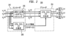
図2は、エンコーダ202とデコーダ204とを備える一般バイノーラルキュー符号化(BCC)音声処理システム200を示すブロック図である。エンコーダ202は、ダウンミキサ206とBCC推定器208とを含んでいる。
General BCC Processing FIG. 2 is a block diagram illustrating a general binaural cue coding (BCC)
ダウンミキサ206は、C>E=1である、C個の入力音声チャネルxi(n)をE個の送信音声チャネルyi(n)に変換する。この明細書では、変数nを用いて表す信号は時間領域信号であって、変数kを用いて表す信号は周波数領域信号である。特定の実施例によるが、時間領域または周波数領域のいずれかでダウンミキシングを行うことが可能である。BCC推定器208は、BCCコードをC個の入力音声チャネルから生成して、E個の送信音声チャネルを基準として、帯域内または帯域外サイド情報のいずれかとしてそれらのBCCコードを送信する。典型的なBCCコードは、1つ以上のチャネル間時間差(ICTD)と、チャネル間レベル差(ICLD)と、周波数および時間の関数として、特定の対の入力チャネル間で推定した、チャネル間相関(ICC)データとを含んでいる。特定の実施例では、どの特定の対の入力チャネルでBCCコードを推定するか要求している。
The
ICCデータは、音源の知覚した幅に関するバイノーラル信号のコヒーレンスに対応している。音源がより広くなると、得られるバイノーラル信号の左右のチャネル間のコヒーレンスがより低下する。例えば、ホールのステージいっぱいに広がるオーケストラに対応するバイノーラル信号のコヒーレンスは、通常、独奏している1つのバイオリンに対応するバイノーラル信号のコヒーレンスより低い。一般に、コヒーレンスが低い音声信号は通常、聴覚空間ではより広がって知覚される。従って、ICCデータは通常、明白な音源の幅と、聴取者が包み込まれた状態の度合いに関係する。すなわち、J.ブラウエルト、「人のサウンドローカリゼーションの精神物理学」(MIT出版、1983年)を参照のこと。 The ICC data corresponds to the binaural signal coherence related to the perceived width of the sound source. As the sound source becomes wider, the coherence between the left and right channels of the obtained binaural signal is further reduced. For example, the coherence of a binaural signal corresponding to an orchestra that extends throughout the hall stage is usually lower than the coherence of a binaural signal corresponding to a single violin playing alone. In general, audio signals with low coherence are usually perceived more widely in auditory space. Thus, ICC data is usually related to the apparent width of the sound source and the degree to which the listener is encased. That is, J.H. See Brauert, “Psychophysics of Human Sound Localization” (MIT Publishing, 1983).

図2に示すBCC処理の他に、一般BCC音声処理システムは、さらに符号化段、復号化段をさらに備え、エンコーダで音声信号を圧縮して、デコーダで音声信号を復元することもできる。これらの音声コーデックは、パルスコード変調(PCM)、差動PCM(DPCM)、または適応DPCM(ADPCM)に基づいた、従来の音声圧縮/復元技術に基づくものであってもよい。 In addition to the BCC processing shown in FIG. 2, the general BCC audio processing system further includes an encoding stage and a decoding stage, and the audio signal can be compressed by the encoder and the audio signal can be restored by the decoder. These audio codecs may be based on conventional audio compression / decompression techniques based on pulse code modulation (PCM), differential PCM (DPCM), or adaptive DPCM (ADPCM).
ダウンミキサ206が1つの和信号(すなわち、E=1)を生成する場合は、BCC符号化により、モノラル音声信号を表すのに必要なものよりも若干高いビットレートでマルチチャネル音声信号を表すことが可能である。これは、チャネル対の間の推定したICTD、ICLD、およびICCデータが、音声波形よりも約2桁小さい情報を含んでいるからである。
If the
BCC符号化は、ビットレートが低いことばかりでなく、その後方互換性の点でも関心を集めている。1つの送信した和信号は、元のステレオまたはマルチチャネル信号のモノラルダウンミキシングに対応している。ステレオまたはマルチチャネル音響再生をサポートしていない受信機にとって、送信した和信号を聴取することは、薄型モノラル再生装置で音声素材を表す有効な方法である。従って、BCC符号化を用いて、モノラル音声素材をマルチチャネル音声にすることが必要な既存のサービスを向上させることもできる。例えば、BCCサイド情報が、既存の伝送チャネルに埋め込むことができれば、ステレオまたはマルチチャネル再生が行えるように、既存のモノラル音声無線放送システムを向上させることができる。マルチチャネル音声を、ステレオ音声に対応する2つの和信号にダウンミキシングする際に、類似の能力が存在する。 BCC coding is attracting attention not only for its low bit rate, but also for its backward compatibility. One transmitted sum signal corresponds to monaural downmixing of the original stereo or multichannel signal. For receivers that do not support stereo or multi-channel sound reproduction, listening to the transmitted sum signal is an effective way to represent audio material with a thin mono reproduction device. Therefore, it is possible to improve existing services that require monaural audio material to be multi-channel audio by using BCC encoding. For example, if the BCC side information can be embedded in an existing transmission channel, the existing monaural audio wireless broadcasting system can be improved so that stereo or multi-channel playback can be performed. Similar capabilities exist in downmixing multi-channel audio into two sum signals corresponding to stereo audio.
BCCにより、ある時間および周波数分解能で音声信号を処理する。用いられる周波数分解能は、人間の聴覚システムの周波数分解能が主な動機となっている。心理音響学では、空間知覚は、音響入力信号の重要な帯域表現に基づいている可能性が一番高いことを示唆している。人間の聴覚システムの重要な帯域幅と同じか、または比例する帯域幅のサブバンドを有する可逆フィルタバンク(例えば、高速フーリエ変換(FFT)または直交ミラーフィルタ(QMF)に基づくもの)を用いて、この周波数分解能について考える。 BCC processes audio signals with a certain time and frequency resolution. The frequency resolution used is mainly the frequency resolution of the human auditory system. Psychoacoustics suggests that spatial perception is most likely based on an important band representation of the acoustic input signal. Using a reversible filterbank (e.g., based on Fast Fourier Transform (FFT) or Quadrature Mirror Filter (QMF)) with subbands of bandwidth equal to or proportional to the critical bandwidth of the human auditory system, Consider this frequency resolution.
一般ダウンミキシング
好適な実施例では、送信した和信号は、入力音声信号の全信号成分を含んでいる。目的は、各信号成分を完全に維持することである。音声入力チャネルを単純に加算することは、信号成分が増幅したり、減衰したりすることがよくある。言い換えれば、“単純に”加算した信号成分のパワーが、各チャネルの対応する信号成分のパワーの合計よりも大きかったり、小さかったりすることがよくある。和信号の信号成分のパワーが全入力チャネルの対応するパワーとほぼ同じになるように、和信号を等しくするダウンミキシング技術を用いることができる。
General Downmixing In the preferred embodiment, the transmitted sum signal contains all signal components of the input audio signal. The goal is to maintain each signal component perfectly. Simply adding the audio input channels often amplifies or attenuates the signal components. In other words, the power of the signal components summed “simply” is often greater or less than the sum of the powers of the corresponding signal components of each channel. A down-mixing technique that equalizes the sum signals can be used so that the power of the signal components of the sum signal is approximately the same as the corresponding power of all input channels.
図3は、BCCシステム200のある実施例による、図2のダウンミキサ206に用いることができるダウンミキサ300を示すブロック図である。ダウンミキサ300は、各入力チャネルxi(n)のフィルタバンク(FB)302と、ダウンミキシングブロック304と、オプションのスケーリング/遅延ブロック306と、各符号化したチャネルyi(n)の逆FB(IFB)308とを備える。
FIG. 3 is a block diagram illustrating a
オプションのスケーリングを行う他に、またはこの代わりに、スケーリング/遅延ブロック306は、オプションで信号を遅延してもよい。
In addition to or instead of performing optional scaling, the scaling /
各逆フィルタバンク308は、周波数領域の対応するスケーリング係数のセットを、対応するデジタル送信チャネルyi(n)のフレームに変換する。
Each
図3は、C個の入力チャネルすべてを周波数領域に変換して、続いてダウンミキシングを行っているが、別の実施例として、1つ以上(しかし、C−1よりも小さい数)のC個の入力チャネルについて、図3に示す処理の一部またはすべてを省略して、同等の数の変更していない音声チャネルとして送信してもよい。特定の実施例によるが、送信BCCコードの生成に、図2のBCC推定器208がこれらの変更していない音声チャネルを用いても、用いなくてもよい。
FIG. 3 shows all C input channels converted to the frequency domain, followed by downmixing, but as another example, one or more (but less than C-1) C For some input channels, some or all of the processing shown in FIG. 3 may be omitted and transmitted as an equivalent number of unchanged voice channels. Depending on the particular embodiment, the
係数e(k)は、次の式(5)から得られる。
各遅延406は、ICTDデータの対応するBCCコードに基づいて、遅延値di(k)を適用して、再生チャネルの特定の対の間で確実に所望のICTD値が現れるようにする。各乗算器408は、ICLDデータの対応するBCCコードに基づいて、倍率ai(k)を適用して、特定の対の再生チャネルの間で確実に所望のICLD値が現れるようにする。相関ブロック410は、ICCデータの対応するBCCコードに基づいて、非相関演算Aを行って、特定の対の再生チャネルの間で確実に所望のICC値が現れるようにする。さらに相関ブロック410の演算の記載は、米国出願第10/155,437号2002年5月24日出願(代理人整理番号第Baumgarte2−10)に記載されている。
Each
ICLD合成を行うには、サブバンド信号のスケーリングを行うだけでよいので、ICLD値の合成は、ICTD値およびICC値の合成よりも煩わしくない。ICLDキューは最も一般的に用いられる方向キューなので、ICLD値により元の音声信号のICLDキューを近似することは、通常、さらに重要なことである。従って、ICLDデータを、全チャネル対の間で推定する場合もある。好ましくは、各再生チャネルのサブバンドパワーが、元の入力音声チャネルの対応するパワーを近似するように、各サブバンドの倍率ai(k)(1・i・C)が選択される。 In order to perform ICLD synthesis, it is only necessary to perform scaling of the subband signal. Therefore, synthesis of ICLD values is less troublesome than synthesis of ICTD values and ICC values. Since the ICLD cue is the most commonly used direction cue, it is usually more important to approximate the ICLD cue of the original audio signal by the ICLD value. Thus, ICLD data may be estimated between all channel pairs. Preferably, the magnification a i (k) (1 · i · C) of each subband is selected so that the subband power of each playback channel approximates the corresponding power of the original input audio channel.
目的の1つは、ICTD値およびICC値を合成するために、比較的少ない回数の信号変更を適用することである。従って、BCCデータは、全チャネル対のICTD値およびICC値を含んでいなくてもよい。その場合は、BCC合成装置400は、あるチャネル対の間だけでICTD値およびICC値を合成する。
One purpose is to apply a relatively small number of signal changes to synthesize the ICTD and ICC values. Therefore, the BCC data may not include the ICTD values and ICC values for all channel pairs. In that case, the
図4は、続いてアップミキシングおよびBCC処理を行うために、E個の送信チャネルをすべて周波数領域に変換することを示しているが、別の実施例では、(すべてではないが)1つ以上のE個の送信チャネルについて、図4に示す処理の一部またはすべてを回避してもよい。例えば、1つ以上の送信チャネルが、アップミキシングを行っていない、変更していないチャネルであってもよい。1つ以上のC個の再生チャネルの他に、必ずしも行う必要はないが、これらの変更していないチャネルを順に、基準チャネルとして用いて、BCC処理を行って、1つ以上の他の再生チャネルを合成してもよい。いずれの場合でも、このような変更していないチャネルを遅延して残りの再生チャネルの生成に用いられるアップミキシングおよび/またはBCC処理に必要な処理時間を補償することもできる。 FIG. 4 illustrates converting all E transmission channels to the frequency domain for subsequent upmixing and BCC processing, but in another embodiment, one or more (but not all). For the E transmission channels, some or all of the processing illustrated in FIG. 4 may be avoided. For example, one or more transmission channels may be channels that have not been upmixed and have not been changed. Other than one or more C playback channels, it is not always necessary, but these unchanged channels are sequentially used as a reference channel to perform BCC processing and one or more other playback channels. May be synthesized. In either case, such unmodified channels can be delayed to compensate for the processing time required for upmixing and / or BCC processing used to generate the remaining playback channels.
図4は、Cは元の入力チャネルの数である、C個の再生チャネルをE個の送信チャネルから合成することを示しているが、BCC合成は、再生チャネルの数に限られるわけではないことに留意されたい。一般に、再生チャネルの数を任意の数のチャネルとすることができ、Cより多い、または少ない数や、再生チャネルの数が送信チャネルの数以下である場合も考えられる。 FIG. 4 shows that C playback channels are combined from E transmission channels, where C is the number of original input channels, but BCC combining is not limited to the number of playback channels. Please note that. In general, the number of playback channels can be any number, and there are cases where the number is greater or less than C, or the number of playback channels is less than or equal to the number of transmission channels.
音声チャネル間の“知覚的関連差”
1つの和信号を仮定し、ICTD、ICLD、およびICCが元の音声信号の対応するキューを近似するように、BCCは、ステレオ音声信号またはマルチチャネル音声信号を合成する。以下では、聴覚空間イメージ属性に関連したICTD、ICLD、およびICCの役割が説明される。
“Perceptually related differences” between audio channels
Assuming one sum signal, BCC synthesizes a stereo or multi-channel audio signal so that ICTD, ICLD, and ICC approximate the corresponding cues of the original audio signal. In the following, the role of ICTD, ICLD, and ICC in relation to auditory space image attributes is described.
空間聴力の知識は、1つの聴覚イベントについて、ICTDおよびICLDは、知覚した方向に関係していることを意味している。1つの音源のバイノーラル室内インパルス応答(BRIR)を考える場合、聴覚イベントの幅、聴取者が包み込まれた状態、BRIRのはじめの部分および後の部分について推定したICCデータの間に、関係がある。しかしながら、ICCと、(単にBRIRばかりでなく)一般的な信号のこれらの特性との間の関係は、直接的なものではない。 Knowledge of spatial hearing means that for one auditory event, ICTD and ICLD are related to the perceived direction. When considering the binaural room impulse response (BRIR) of a single sound source, there is a relationship between the width of the auditory event, the state in which the listener is encapsulated, and the ICC data estimated for the first and subsequent parts of the BRIR. However, the relationship between ICC and these characteristics of a typical signal (not just BRIR) is not straightforward.
ステレオ音声信号およびマルチチャネル音声信号は通常、アクティブな音源信号を、同時に、閉鎖空間でのレコーディングから得られる反射信号成分と重畳したもの、または、レコーディングエンジニアによって、人工的に生成した空間印象を加えられたものの、複雑な混合物を含んでいる。異なる源信号およびそれらの残響は、時間周波数平面で異なる領域を占めている。このことは、ICTD,ICLD、およびICCに反映され、時間および周波数の関数として変化する。この場合は、瞬時ICTD、ICLD、ICC、聴覚イベント方向、空間印象の間の関係は、明白でない。BCCを行うある実施の形態の手法は、元の音声信号の対応するキューを近似するように、これらのキューを盲目的に合成することである。 Stereo and multi-channel audio signals usually add an active sound source signal simultaneously with a reflection signal component obtained from recording in a closed space, or add a spatial impression artificially generated by a recording engineer. But it contains a complex mixture. Different source signals and their reverberations occupy different regions in the time frequency plane. This is reflected in ICTD, ICLD, and ICC and varies as a function of time and frequency. In this case, the relationship between instantaneous ICTD, ICLD, ICC, auditory event direction, and spatial impression is not obvious. One embodiment approach to BCC is to blindly synthesize these cues so as to approximate the corresponding cues of the original speech signal.
時間等価矩形帯域幅(ERB)の2倍と等しいサブバンドの帯域幅を持つフィルタバンクを用いる。非公式な聴き取りでは、より高い周波数分解能を選択した場合は、BCCの音声品質があまり向上しないことが明らかになっている。デコーダに送信する必要があるICTD、ICLD、およびICC値が小さくなり、従ってビットレートが低くなるので、より低い周波数分解能が望ましい。 A filter bank having a subband bandwidth equal to twice the time equivalent rectangular bandwidth (ERB) is used. Informal listening has shown that BCC audio quality does not improve much if a higher frequency resolution is selected. A lower frequency resolution is desirable because the ICTD, ICLD, and ICC values that need to be transmitted to the decoder are smaller, and therefore the bit rate is lower.
時間分解能については、ICTD、ICLD、およびICCは、通常、通常の時間間隔で考えられている。ICTD、ICLD、およびICCを約4〜16ミリ秒毎に考える場合に、高い音効果が得られる。キューを非常に短時間の間隔で考える場合を除いて、先行音効果については直接考えないことに留意されたい。進みおよび遅れが時間間隔になり、1セットのキューが合成され、進みの局所的な優越については考えない場合は、音刺激の従来の遅れ進み対を想定する。このことにもかかわらず、BCCにより、平均で、平均MUSHRAスコアで約87(すなわち、“非常によい”音声品質)の音声品質になり、ある音声信号については100近くにまでなる。 For time resolution, ICTD, ICLD, and ICC are usually considered at normal time intervals. High sound effects are obtained when ICTD, ICLD, and ICC are considered approximately every 4-16 milliseconds. Note that we do not think directly about the precedence effect unless we consider the cue at very short intervals. If the advance and delay become time intervals and a set of cues is synthesized and we don't consider the local superiority of the advance, we assume a traditional delayed advance pair of sound stimuli. Despite this, BCC, on average, has an average MUSHRA score of approximately 87 (ie, “very good” speech quality), and close to 100 for some speech signals.
基準信号と合成した信号との間の、しばしば見受けられる知覚的に小さな差は、通常の時間間隔でICTD、ICLD、およびICCを合成することにより、幅の広い聴覚空間イメージ属性の関するキューを暗黙的に考えることを意味している。以下では、ICTD、ICLD、およびICCが、聴覚空間イメージ属性の幅とどのように関連しているかについて、説明する。 The small perceptual differences often seen between the reference signal and the synthesized signal imply a cue for wide auditory spatial image attributes by synthesizing ICTD, ICLD, and ICC at regular time intervals. It means to think about it. The following describes how ICTD, ICLD, and ICC are related to the width of the auditory space image attribute.
空間キューの推定
以下では、ICTD、ICLD、およびICCをどのように推定するか、説明する。これらの(量子化および符号化)空間キューを伝送するビットレートは、わずか数キロビット/秒なので、BCCにより、1つの音声チャネルに必要なものに近いビットレートで、ステレオ音声信号およびマルチチャネル音声信号を送信することが可能である。
In the following, how to estimate ICTD, ICLD and ICC will be described. The bit rate for transmitting these (quantized and coded) spatial cues is only a few kilobits / second, so BCC allows stereo and multi-channel audio signals at bit rates close to those required for one audio channel. Can be sent.
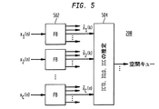
図5は、本発明の一実施の形態による、図2のBCC推定器208を示すブロック図である。BCC推定器208は、図3のフィルタバンク302と同じであってもよいフィルタバンク(FB)502と、フィルタバンク502によって生成されるそれぞれ異なる周波数サブバンドに対するICTD、ICLD、およびICC空間キューを生成する推定ブロック504とを備える。
FIG. 5 is a block diagram illustrating the
・ICTD[サンプル]
![]()
![]()
次の式(8)から得られる正規化相互相関関数の短時間推定値による。
![]()
![]()
・ICLD[dB]:
・ICC:
![]()
![]()
正規化相互相関の絶対値について考慮し、c12(k)の範囲は[0,1]であることに留意されたい。 Note that the range of c 12 (k) is [0, 1], considering the absolute value of the normalized cross-correlation.
マルチチャネル音声信号に対するICTDICLD、およびICCの推定
入力チャネルが3つ以上ある場合は、通常、基準チャネル(例えば、チャネルナンバー1)と他のチャネルとの間でICTDおよびICLDを定義することで十分である。図6には、C=5チャネルの場合を示している。τ1c(k)およびΔ12(k)はそれぞれ、基準チャネル1とチャネルcとの間のICTDおよびICLDを表す。
ICTDICLD and ICC estimation for multi-channel audio signals If there are more than two input channels, it is usually sufficient to define ICTD and ICLD between the reference channel (eg, channel number 1) and other channels. is there. FIG. 6 shows the case of C = 5 channels. τ 1c (k) and Δ 12 (k) represent ICTD and ICLD between
ICTDおよびICLDとは反対に、ICCは通常、より自由度がある。定義されているICCは、考えられるすべての入力チャネル対の間で異なる値をとることができる。C個のチャネルの場合、C(C−1)/2個の考えられるチャネル対がある。例えば、5チャネルの場合は、図7(a)に示すように10個のチャネル対がある。しかしながら、このような方法では、各時間インデックスでの各サブバンドに対し、C(C−1)/2個のICC値を推定して送信することが必要になり、計算量が大きくなり、ビットレートが高くなってしまう。 Contrary to ICTD and ICLD, ICC is usually more flexible. The defined ICC can take on different values between all possible input channel pairs. For C channels, there are C (C-1) / 2 possible channel pairs. For example, in the case of 5 channels, there are 10 channel pairs as shown in FIG. However, in such a method, it is necessary to estimate and transmit C (C-1) / 2 ICC values for each subband at each time index, which increases the amount of calculation and increases the bit rate. The rate will be high.
また、各サブバンドに対して、ICTDおよびICLDが、サブバンドの対応する信号成分の聴覚イベントを表現する方向を求める。次に、サブバンド1つ毎に1つのICCパラメータを用いて、全音声チャネル間の全体的なコヒーレンスを記述してもよい。各時間インデックスで、各サブバンドで最もエネルギーが大きい2つのチャネルの間だけで、ICCキューを推定して送信することにより、良い結果を得ることができる。このことを、図7(b)に示す。時刻k−1およびkで、チャネル対(3、4)および(1、2)それぞれが最も強い。発見的規則を用いて、他のチャネル対の間のICCを求めてもよい。 For each subband, ICTD and ICLD determine the direction in which the auditory event of the corresponding signal component of the subband is expressed. The overall coherence between all voice channels may then be described using one ICC parameter for each subband. Good results can be obtained by estimating and transmitting the ICC queue only between the two channels with the highest energy in each subband at each time index. This is shown in FIG. At times k-1 and k, channel pairs (3, 4) and (1, 2) are strongest, respectively. Heuristic rules may be used to determine the ICC between other channel pairs.
ICTD合成
次の式(12)により、ICTDτ1c(k)から遅延dcを求める。遅延dcの最大大きさを最小にするように、基準チャネルd1の遅延が算出される。変更するサブバンド信号が少なくなるほど、アーティファクトが発生する危険性がより少なくなる。サブバンドのサンプリングレートが、ICTD合成に対する時間分解能が十分高くならない場合は、適したオールパスフィルタを用いることにより、より正確に遅延を行うようにする。
ICLD合成
チャネルcおよび基準チャネル1の間で出力サブバンド信号が所望のICLDΔ12(k)を有するようにするために、利得係数acは、次の式(13)を満たす必要がある。
ICC合成
ある実施の形態では、ICC合成の目的は、ICTDおよびICLDに影響を与えることなく、遅延およびスケーリングを行った後で、サブバンド間の相関を低減することである。平均変動が各サブバンド(聴覚的に重要な帯域)でゼロになるように、周波数の関数としてICTDおよびICLDが効果的に変化するように、図8のフィルタhcを設計することにより、このことを行うことが可能である。
ICC Synthesis In one embodiment, the purpose of ICC synthesis is to reduce the correlation between subbands after delay and scaling without affecting ICTD and ICLD. This is done by designing the filter hc of FIG. 8 so that ICTD and ICLD effectively change as a function of frequency so that the average variation is zero in each subband (auditoryly important band). Can be done.
図9は、周波数の関数として、ICTDおよびICLDがサブバンド内でどのように変化するかを示している。ICTDおよびICLD変動の振幅が、非相関の度合いを求め、ICCの関数として制御する。ICTDは滑らかに変化し(図9(a)に示す)、ICLDはランダムに変化する(図9(b)に示す)ことに留意されたい。ICLDを、ICTDのように滑らかに変化させることもできるが、このことにより、得られる音声信号をさらに特徴付けることになる。 FIG. 9 shows how ICTD and ICLD vary within a subband as a function of frequency. The amplitude of ICTD and ICLD variation determines the degree of decorrelation and controls it as a function of ICC. Note that ICTD changes smoothly (shown in FIG. 9 (a)) and ICLD changes randomly (shown in FIG. 9 (b)). ICLD can be changed as smoothly as ICTD, but this further characterizes the resulting audio signal.
マルチチャネルICC合成を行うのに特に適した、ICCを合成する別の方法は、次の文献に詳細に記載されている。C.フォーラ、「パラメトリックマルチチャネル音声符号化:コヒーレンスキューの合成(Parametric multi−channel audio coding: Synthesis of coherence cues)」(IEEE会報、スピーチおよびオーディオ学会、2003年)」(IEEE会報、スピーチおよびオーディオ学会、2003年)。この要旨は、ここに引例として組み込まれている。時間および周波数の関数として、一定量のアーティフィシャルな後期残響を出力チャネルそれぞれに加算して、所望のICCを得る。また、得られる信号のスペクトルエンベロープが元々の音声信号のスペクトルエンベロープに近づくように、スペクトル変更を行うこともできる。 Another method of synthesizing ICC, which is particularly suitable for performing multi-channel ICC synthesis, is described in detail in the following document. C. Fora, “Parametric Multi-Channel Speech Coding: Synthesis of coherence cues” (IEEE Bulletin, Speech and Audio Society, 2003). 2003). This summary is incorporated herein by reference. As a function of time and frequency, a certain amount of artistic late reverberation is added to each output channel to obtain the desired ICC. In addition, the spectrum can be changed so that the spectrum envelope of the obtained signal approaches the spectrum envelope of the original audio signal.
ステレオ信号(または音声チャネル対)に対するICC合成技術に関係する、または関係しない他の技術が、次の文献に記載されている。E.シュイエールス(Schuijers)、W.オーメン(Oomen)、B.デン・ブリンカー(den Brinker)、J.ブレーバールト(Breebaart)、「高品質音声のためのパラメトリック符号化の進歩(Advances in parametric coding for high−quality audio)」(音声工学学会第114回大会予稿集、2003年3月)、J.エングデガールド(Engdegard)、Hプルンハーゲン(Purnhagen)、J.ローデン(Roden)、L.リルジェリド(Liljeryd)、「パラメトリックステレオ符号化における合成環境(Synthetic ambience in parametric stereo coding)」(音声工学学会第117回大会予稿集2004年5月)。これらの要旨は、ここに引例として組み込まれている。 Other techniques related to or not related to ICC synthesis techniques for stereo signals (or audio channel pairs) are described in the following references. E. Schuijers, W.M. Omen, B.I. Den Brinker, J.A. Brebaart, “Advances in parametric coding for high-quality audio” (Proceedings of the 114th Annual Conference of Speech Engineering, March 2003), J. Am. Engdegard, H. Purnhagen, J.A. Roden, L. Liljeryd, “Synthetic environment in parametric stereo coding” (Proceedings of the 117th Annual Conference of the Speech Engineering Society, May 2004). These summaries are incorporated herein by reference.
CチャネルからEチャネルへのBCC
前述のように、2つ以上の伝送チャネルでBCCを行うことができる。BCCのバリエーションが、1つの(送信した)チャネルだけでなく、E個のチャネルとしてもC個の音声チャネルを表すことについて、説明してきたが、これを、CチャネルからEチャネルへのBCCと記載する。CチャネルからEチャネルへのBCCを行う、(少なくとも)2つの目的がある。
・1つの伝送チャネルで、BCCは、既存のモノラルシステムをグレードアップして、ステレオ音声再生またはマルチチャネル音声再生を行う後方互換性経路を提供する。グレードアップしたシステムは、既存のモノラルインフラを介してBCCダウンミキシング和信号を送信し、さらにBCCサイド情報を送信する。CチャネルからEチャネルへのBCCを、Cチャネル音声のEチャネル後方互換性符号化に適用することができる。
・CチャネルからEチャネルへのBCCは、送信チャネルの数を異なる度合いで低減するという意味で、拡張性を導入する。送信する音声チャネルの音声品質がさらに向上することが期待できる。
ICTD、ICLD、およびICCキューをどのように定義するかというような、CチャネルからEチャネルへのBCCの信号処理の詳細は、米国出願第10/762,100号01/20/042004年1月20日出願(Faller13−1)に記載されている。
BCC from C channel to E channel
As described above, BCC can be performed on two or more transmission channels. It has been described that BCC variations represent C voice channels not only as one (transmitted) channel but also as E channels, which is described as BCC from C channel to E channel. To do. There are (at least) two purposes of performing BCC from C channel to E channel.
• With one transmission channel, BCC upgrades the existing monaural system to provide a backward compatible path for stereo audio playback or multi-channel audio playback. The upgraded system transmits a BCC downmixing sum signal via the existing monaural infrastructure, and further transmits BCC side information. C channel to E channel BCC can be applied to E channel backward compatible encoding of C channel speech.
-BCC from C channel to E channel introduces extensibility in the sense of reducing the number of transmission channels to different degrees. It can be expected that the voice quality of the voice channel to be transmitted is further improved.
Details of CCC to E channel BCC signal processing, such as how to define ICTD, ICLD, and ICC queues, can be found in US application Ser. No. 10 / 762,100 01/20/04 January 2004. It is described in the 20th application (Faller 13-1).
拡散音波形整形
ある実施の形態では、BCC符号化は、ICTD、ICLDおよびICC合成のためのアルゴリズムを含む。ICCキューは、対応するサブバンドの信号成分を非相関させることによって合成されることができる。これは、ICLD、ICTDの周波数に依存するバリエーションおよびICLD(全通過のフィルタリング)の、または、残響アルゴリズムに関連した考えを有する周波数に依存するバリエーションによってされることができる。
Diffusion Sonic Shaping In one embodiment, BCC encoding includes algorithms for ICTD, ICLD, and ICC synthesis. ICC cues can be synthesized by decorrelating the signal components of the corresponding subbands. This can be done by ICLD, ICTD frequency-dependent variations and ICLD (all-pass filtering) or frequency-dependent variations that have ideas related to the reverberation algorithm.
これらの技術が音声信号に適用される場合に、信号の時間エンベロープ特性は保存されない。具体的には、一時的現象に適用される場合に、瞬間的な信号エネルギーは特定の期間広がりそうである。これは、プレエコーまたはくたびれた一時的現象のアーティファクトである。 When these techniques are applied to an audio signal, the time envelope characteristics of the signal are not preserved. Specifically, when applied to a transient phenomenon, the instantaneous signal energy is likely to spread for a certain period of time. This is an artifact of pre-echo or tedious transient phenomena.
本発明のある実施の形態の一般的な原理は、BCCデコーダによって合成される音が元のそれと類似しているスペクトル特性を有しなければならないだけでなく、類似の知覚的な特性を有するために全く密接に元の時間エンベロープにも似ていなければならないという観察に関する。通常、これは、各信号チャネルの時間エンベロープに近づくために時間様々なスケーリング動作を適用する動的なICLD合成を含むことによって、BCCのような方式において成し遂げられる。しかしながら、一時的な信号(音の立ち上がり、打楽器、その他)という場合は、このプロセスの時間軸分解度は、十分に密接に元の時間エンベロープに近い合成された信号を生成するために、充分ではなくてもよい。このセクションは、十分に微細な時間分解能によってこれをするために、多くの方法を記載する。 The general principle of an embodiment of the present invention is that the sound synthesized by the BCC decoder not only has a spectral characteristic similar to that of the original, but also has a similar perceptual characteristic. With respect to the observation that it must closely resemble the original time envelope. Typically this is accomplished in a BCC-like manner by including dynamic ICLD combining that applies time varying scaling operations to approach the time envelope of each signal channel. However, in the case of a transient signal (sound rise, percussion instrument, etc.), the time resolution of this process is not sufficient to produce a synthesized signal that is close enough to the original time envelope. It does not have to be. This section describes a number of ways to do this with sufficiently fine temporal resolution.
さらに、元の信号の時間エンベロープにアクセスしないBCCデコーダのために、アイデアは、その代わりに近似として送信された「合計信号(s)」の時間エンベロープをとることである。このように、このようなエンベロープ情報を伝達するために、BCCエンコーダからBCCデコーダまで送信されるのに必要なサイド情報がない。要約すると、本発明は、以下の原理に依存する:
・送信された音声チャンネル(すなわち、「合計チャネル」)または、これらのチャネルの線形結合に基づくBCC合成は、(例えば、BCCブロックサイズより著しく微細な)高時間分解を有するそれらの時間エンベロープに対する時間エンベロープ抽出器によって分析される。
・各出力チャネルに対する次の合成された音は、ICC合成の後でさえ、できるだけ密接に抽出器により求められた時間エンベロープに整合するように、形成される。これは、一時的な信号の場合さえ、合成された出力音がICC合成/信号非相関性処理によって著しく劣化しないことを確実にする。
Furthermore, for BCC decoders that do not access the time envelope of the original signal, the idea is to instead take the time envelope of the “total signal (s)” transmitted as an approximation. Thus, in order to convey such envelope information, there is no side information necessary to be transmitted from the BCC encoder to the BCC decoder. In summary, the present invention relies on the following principles:
BCC synthesis based on transmitted audio channels (ie “total channels”) or linear combination of these channels is time for those time envelopes with high temporal resolution (eg, significantly finer than BCC block size) Analyzed by envelope extractor.
The next synthesized sound for each output channel is formed to match the time envelope determined by the extractor as closely as possible even after ICC synthesis. This ensures that the synthesized output sound is not significantly degraded by the ICC synthesis / signal decorrelation process, even for transient signals.
本発明の一実施の形態によれば、図10は、少なくとも一部のBCCデコーダ1000で、ブロック図表示式を示す。図10において、ブロック1002は、少なくとも、ICC合成を含むBCC合成処理を表す。BCC合成ブロック1002は、ベースチャンネル1001を受信して、合成されたチャネル1003を生成する。特定の実施例において、ブロック1002は図4のブロック406、408および410の処理を表す。そこにおいて、ベースチャンネル1001はブロック404をアップミキシングすることによって発生する信号であり、そして、合成されたチャネル1003は相関ブロック410によって生成する信号である。図10は、処理が1つのベースチャンネル1001’およびその対応する合成されたチャネルのために行うことを表す。類似の処理は、各他のベースチャンネルおよびその対応する合成されたチャネルにも適用される。
FIG. 10 illustrates a block diagram representation formula in at least some
エンベロープ抽出器1004は、ベースチャネル1001’の微細な時間エンベロープaを決定し、そして、エンベロープ抽出器1006は、合成されたチャネル1003’の微細な時間エンベロープbを決定する。逆エンベロープ調整装置1008は、フラット(例えば、一様な)時間エンベロープを有する平坦化された信号1005’を生成するために、合成されたチャネル1003’のエンベロープ(すなわち、時間的微細なエンベロープの「平坦化」)を規格化するために、エンベロープ抽出器1006から時間エンベロープbを使用する。特定の実施例に応じて、平坦化は、アップミキシングする、前または後ろに適用されることができる。エンベロープ調整装置1010は、ベースチャネル1001の時間エンベロープと実質的に等しい時間エンベロープを有している出力信号1007’を生成するために、平坦化された信号1005’における元の信号エンベロープを再び課すためのエンベロープ抽出器1004から時間エンベロープaが使用される。
The
実施の形態に応じて、この時間エンベロープ処理(また、本明細書において、「エンベロープ整形」と称される)は、全ての合成されたチャネル(示すように)に、または、合成されたチャネル(その後記載されているように)の直交化された一部(例えば後期残響パート、非相関している一部)だけに適用されることができる。さらに、実施例に応じて、エンベロープ整形は、時間領域信号に、または、周波数に依存する方法(例えば、時間エンベロープは、異なる周波数で個々に推定されて、課される)で適用されることができる。 Depending on the embodiment, this time envelope processing (also referred to herein as “envelope shaping”) can be applied to all synthesized channels (as shown) or to synthesized channels ( Can be applied to only the orthogonalized part (eg, late reverberation part, non-correlated part). Further, depending on the embodiment, the envelope shaping may be applied to the time domain signal or in a frequency dependent manner (eg, the time envelope is estimated and imposed individually at different frequencies). it can.
逆エンベロープ調整装置1008およびエンベロープ調整装置1010は、異なる方法で行うことができる。1つの実施の形態の形式において、信号のエンベロープは、時間可変振幅変更関数(例えば、逆エンベロープ調整装置1008に対する1/bおよびエンベロープ調整装置1010に対するa)を有する信号の時間領域のサンプル(または、スペクトル/サブバンドサンプル)の乗算によって乗算される。あるいは、周波数の上の信号のスペクトル表現の畳込み/フィルタリングが、低いビットレートな音声符合化の量子化雑音を成形するために既知の発明において使われて、それに類似した方法で使われることができる。同様に、信号の時間エンベロープは、信号の時間が構築する分析によって、または、周波数の上の信号スペクトルの自己相関を調べることによって直接抽出されることもできる。
The inverse
図11は、図4のBCC合成装置400の条件で、図10のエンベロープ整形方式の典型的なアプリケーションを例示する。本実施の形態において、一つの送信された合計信号s(n)があり、C個のベース信号が、その合計信号を複製することにより生成され、そして、エンベロープ整形が、個々に異なるサブバンドに適用される。別の実施例では、遅延、スケーリングおよび他の処理の順序は、異なってもよい。さらに、別の実施例では、エンベロープ整形は、それぞれに各サブバンドを処理することに制限されない。これは、信号の時間微細構造に関する情報を引き出すために周波数帯の上の共分散を利用する実施例に基づく、特に畳込み/フィルタリングのために当てはまる。
FIG. 11 illustrates a typical application of the envelope shaping method of FIG. 10 under the conditions of the
図11(a)において、時間処理分析1104(TPA)を処理することは、図10のエンベロープ抽出器1004に類似している、そして、各時間処理、1106はエンベロープ抽出器1006、逆エンベロープ調整装置1008および図10のエンベロープ調整装置1010の組合せに類似している(TP)。
In FIG. 11A, processing the time processing analysis 1104 (TPA) is similar to the
図11(b)は、TPA1104の一つの時間領域に基づく実施可能なブロック図を示す。ベース信号サンプルは、二乗され(1110)、次に、ベース信号の時間エンベロープaを特徴づけるためにローパスフィルタされる(1112)。
FIG. 11 (b) shows a possible block diagram based on one time domain of the
図11(c)は、TP1106の一つの時間領域に基づく実施可能なブロック図を示す。合成された信号サンプルは、二乗され(1114)、次に、合成された信号の時間エンベロープbを特徴づけるためにローパスフィルタされる(1116)。倍率(例えば、平方根(a/b))が生成されて(1118)、次に、元のベースチャンネルのそれに実質的に等しい時間エンベロープを有する出力信号を生成するために、合成された信号に適用される(1120)。
FIG. 11 (c) shows a possible block diagram based on one time domain of
TPA1104およびTP1106の他の実施例において、時間エンベロープは、信号サンプルを二乗することによってよりむしろ大きさの演算を使用して特徴づけられる。このような実施の形態では、比率a/bが、平方根演算を適用することなく、倍率として使用してもよい。
In other embodiments of
図11(c)のスケーリング演算が、TP処理の時間領域ベースの実施例に対応しているが、(以下に説明する)図17―18の実施の形態のような、周波数領域信号を使用して、TP処理(TPAおよび逆TP(ITP)処理とともに)は行うこともできる。従って、この明細書の目的においては、用語「スケーリング関数」は、図18bおよびcのフィルタリング演算のように、時間領域または周波数領域のいずれもカバーするように解釈する必要がある。 The scaling operation of FIG. 11 (c) corresponds to a time domain based example of TP processing, but uses a frequency domain signal as in the embodiment of FIGS. 17-18 (described below). TP processing (along with TPA and inverse TP (ITP) processing) can also be performed. Therefore, for the purposes of this specification, the term “scaling function” should be interpreted to cover either the time domain or the frequency domain, such as the filtering operations of FIGS. 18b and c.
一般に、好ましくは、それらが信号パワー(すなわちエネルギー)を変更しないように、TPA1104およびTP1106は設計される。ある実施の形態に応じて、この信号パワーは、例えば、合成ウィンドウまたはパワーの若干の他の適した計測によって定義される期間のチャネル当たりの全体の信号パワーに基づく各チャネルにおける短時間平均信号パワーとしてもよい。従って、エンベロープ整形の前か後で、ICLD合成(例えば、乗算器408を使用して)のためのスケーリングは、適用されることができる。
In general,
なお、各チャネルのために、図11(a)で、2つの出力がある。TP処理は、それらのうちのわずか1つに適用されることに留意されたい。これは、2つの信号成分を混合するICC合成方法を反映する:修正されないおよび直交化された信号、修正されないおよび直交化された信号の成分の比率は、ICCを決定する。図11(a)の図示した実施例において、TPは、直交された信号成分だけ適用される。和ノード1108は、対応する時間的に形作られ、直交化された信号の成分を有する修正されない信号成分に再結合する。
Note that there are two outputs for each channel in FIG. Note that TP processing applies to only one of them. This reflects the ICC synthesis method of mixing two signal components: the ratio of the uncorrected and orthogonalized signal components, the uncorrected and orthogonalized signal components, determines the ICC. In the illustrated embodiment of FIG. 11 (a), TP is applied only to the orthogonal signal components. The
図12は図4のBCC合成装置400の条件で、図10のエンベロープ整形方法の代わりの典型的なアプリケーションを例示する。エンベロープ整形は時間領域において適用される。そのような実施の形態は、ICTD、ICLDおよびICC合成が、実行されるスペクトル表現の時間分解能が、所望の時間エンベロープを課すことにより、「プレエコー」を効果的に妨げることが十分に出来ない場合、正当化されてもよい。例えば、BCCが短いフーリエ変換(STFT)によって行う場合に、このようなケースでもよい。
FIG. 12 illustrates a typical application instead of the envelope shaping method of FIG. 10 under the conditions of the
図12(a)に示すように、TPA1204および各TP1206は時間領域において行う。それが所望の時間エンベロープ(例えば、送信された合計信号から推定されるものとしてのエンベロープ)を有するように、全帯域信号はスケーリングされる。図12(b)および(c)は、図11(b)および(c)に示されるそれらに類似するTPA1204およびTP1206の可能な実施例を示す。
As shown in FIG. 12A, the
本実施の形態では、直交化された信号成分だけでなく、TP処理は、出力信号に適用される。別の実施の形態では、時間領域ベールのTP処理は、所望の場合は、直交化された信号成分にちょうど適用されることができる。修正されないおよび直交化されたサブバンドのケースは、別々の逆フィルタバンクを有する時間領域に変換される。 In the present embodiment, not only the orthogonalized signal components but also TP processing is applied to the output signal. In another embodiment, time-domain veil TP processing can be applied just to the orthogonalized signal components, if desired. Uncorrected and orthogonalized subband cases are transformed into the time domain with separate inverse filter banks.
BCC出力信号の全帯域スケーリングがアーティファクトとして発生する場合があるので、エンベロープ整形は指定された周波数、例えば、特定のカットオフ周波数ftp(例えば、500Hz)より大きい周波数だけに適用されることができる。分析のための周波数範囲(TPA)が、合成(TP)のための周波数範囲と異なる場合もあることに留意されたい。図13(a)および(b)は、TPA1204およびTA1206の可能な実施例を示す。エンベロープ整形は、カットオフ周波数ftpより高い周波数でのみ適用される。特に、図13(a)はハイパスフィルタ1302のさらに示されており、これは、時間エンベロープ特徴を調べる前に、ftpより低い周波数をフィルタする。図13(b)は、2つのサブバンドの間のftpのカットオフ周波数を有する2帯域フィルタバンクがさらに示されており、高い周波数部分のみ、時間的に整形される。次に、2帯域の逆フィルタバンク1306は、出力信号を生成するために、低い周波数部分を時間的に整形される高い周波数部分と再合成する。
Since full-band scaling of the BCC output signal may occur as an artifact, envelope shaping can only be applied to specified frequencies, eg, frequencies greater than a specific cutoff frequency f tp (eg, 500 Hz). . Note that the frequency range for analysis (TPA) may be different from the frequency range for synthesis (TP). FIGS. 13 (a) and (b) show possible embodiments of
図14は、代理人明細書、no.Baumgarte 7−12 04/01/04に出願された米国特許番号10/815,591に記載された後期残響に基づくICC合成方法の条件で、図10のエンベロープ整形方法の典型的なアプリケーションを例示する。本実施の形態において、TPA1404および各TP1406は、図12または図13として時間領域において適用される。しかし、各TP1406は、異なる後期残響(LR)ブロック1402から出力に適用される。
FIG. 14 shows an agent description, no. Illustrates a typical application of the envelope shaping method of FIG. 10 under the conditions of an ICC synthesis method based on late reverberation described in US Pat. No. 10 / 815,591, filed in Baummarte 7-12 04/01/04. . In the present embodiment,
図10に示される方法の変形例である本発明の一実施例によれば、図15は、少なくとも一部のBCCデコーダ1500で、ブロック図表示式を示す。図15において、BCC合成ブロック1502、エンベロープ抽出器1504およびエンベロープ調整装置1510は、図10のBCC合成ブロック1002、エンベロープ抽出器1004およびエンベロープ調整装置1010に類似している。図15において、しかしながら、逆エンベロープ調整装置1508は、BCC合成の後よりはむしろ、図10のようなBCC合成の前に使用される。このようにして、BCC合成が適用される前に、逆エンベロープ調整装置1508はベースチャンネルを平坦化する。
In accordance with one embodiment of the present invention, which is a variation of the method shown in FIG. 10, FIG. 15 shows a block diagram display equation with at least some
図10および図15に示される方法の変形例である本発明の一実施例によれば、図16は、少なくとも一部のBCCデコーダ1600で、ブロック図表示式を示す。図16において、エンベロープ抽出器1604およびエンベロープ調整装置1610は、図15のエンベロープ抽出器1504およびエンベロープ調整装置1510に類似している。図15の実施例において、しかしながら、合成ブロック1602は、それと類似の残響ベースのICC合成が図16に示されることを表す。この場合、エンベロープ整形は無相関の後期残響信号だけに適用され、そして、和ノード1612は時間的に整形された、後期残響信号を最初のベースチャンネル(それは、すでに所望の時間エンベロープを有する)に加える。なお、この場合、逆エンベロープ調整装置は、使用される必要はない、なぜなら、後期残響信号がブロック1602のその生成プロセスのためおよそ平坦な時間エンベロープを有するからである。
In accordance with one embodiment of the present invention, which is a variation of the method shown in FIGS. 10 and 15, FIG. 16 shows a block diagram display equation with at least some
図17は、図4のBCC合成装置400の条件で、図15のエンベロープ整形方式の典型的なアプリケーションを例示する。図17において、TPA1704、逆TP(ITP)1708およびTP1710は、図15におけるエンベロープ抽出器1504、逆エンベロープ調整装置1508およびエンベロープ調整装置1510に類似している。
FIG. 17 illustrates a typical application of the envelope shaping method of FIG. 15 under the conditions of the
この周波数ベースの実施例において、拡散音のエンベロープ整形は、周波数軸に沿って畳み込みを(例えばSTFT)フィルタバンク402の周波数ビンに適用することによって行う。米国特許5,781,888(Herre)および米国を参照する、内容の特許5,812,971(Herre)(それの教示は本願明細書に引用したものとする)は、この技術に関した。
In this frequency-based embodiment, the envelope shaping of the diffuse sound is performed by applying a convolution (eg, STFT) to the frequency bins of the
図18(a)は、図17のTPA1704の1つの実施可能なブロック図を示す。この実施の形態において、TPA1704は、周波数の上のスペクトル係数の直列に最適の予測係数を決定する線形予測分析(LPC)分析動作として行う。このようなLPC分析技術は、例えば、周知であるLPC係数の効果的な算出のための音声符号化および多くのアルゴリズムから、自己相関方法(信号の自己相関関数および次のレビンソン―ダービン再帰の算出を含む)は、公知である。この計算の結果、一組のLPC係数は、信号の時間エンベロープを表す出力で利用できる。
FIG. 18 (a) shows one possible block diagram of the
図18(b)および(c)は図17のITP1708およびTP1710の実施可能なブロック図を示す。両方の実施の形態において、処理される信号のスペクトル係数は、(増減するまたは減少する)周波数の順に処理される。それは、スイッチ回路の丸められ、これらの係数を予測フィルタ処理(およびこの処理の後に元のところへ)により処理されるシリアルオーダーに変換されることによって象徴化される。ITP1708の場合、予測するフィルタリングは、残余の予測を算出して、このようにして時間的信号エンベロープを「平坦化」する。TP1710の場合、逆フィルタは、TPA1704からLPC係数によって表される時間エンベロープを再導入する。
18 (b) and (c) show a possible block diagram of the
TPA1704による信号の時間エンベロープの算出のために、このようなウィンドウが使われる場合、フィルタバンク402の分析ウィンドウの影響を除去することは重要である。これは(知られている)分析ウィンドウ形状によって、または、分析ウィンドウを使用しない別々の分析フィルタバンクを用いることによって、結果として得られるエンベロープを規格化することによって、達成されることも出来る。
When such a window is used for the calculation of the time envelope of the signal by the
図17の畳み込み/フィルタリングに基づく技術は、図16のエンベロープ整形方法の条件でも適用される。エンベロープ抽出器1604およびエンベロープ調整装置1610は、それぞれ、図18(a)のTPAおよび図18(c)のTPに基づいている。
The technique based on convolution / filtering in FIG. 17 is also applied to the conditions of the envelope shaping method in FIG. The
更なる別の実施例
BCCデコーダは、選択的にエンベロープ整形を可能にして/使用不能にするように設計されることができる。例えば、エンベロープ整形の利点が、エンベロープ整形が生成することができるいかなるアーティファクトを支配するように、合成された信号の時間エンベロープが十分に変動する場合に、BCCデコーダは、従来のBCC合成方法を適用することが可能であり、エンベロープ整形を可能にすることができる。この有効な/無効制御は、以下によって成し遂げられることができる:
(1) 一時的な検出:一時的現象が検出される場合、TP処理は使用可である。一時的現象の検知は、一時的現象だけでなく、一時的現象の前後の短時間にも効果的に形作るために先取りの方法で行うことができる。一時的現象を検出する考えられる方法は、以下を含む:
・一時的現象の発生を示しているパワーの急増があるときに送信されたBCCの時間エンベロープが決定する信号を合計するのを観察すること;そして、
・予測(LPC)フィルタの利得を検証すること。LPC予測利得が指定された閾値を上回る場合、信号が一時的であるかまたは非常に変動していると仮定されることができる。LPC分析は、スペクトルの自己相関により算出される。
(2) ランダム性検出:時間エンベロープが疑似ランダム的に変動するときに、シナリオがある。このようなシナリオにおいて、一時的現象は検出されないかもしれない、しかし、TP処理はまだ適用されることができる(例えば、密度の高い拍手信号は、このようなシナリオに対応する)。
Yet another embodiment The BCC decoder can be designed to selectively enable / disable envelope shaping. For example, a BCC decoder applies a conventional BCC synthesis method when the time envelope of the synthesized signal varies sufficiently so that the benefits of envelope shaping dominate any artifact that envelope shaping can generate. And can allow envelope shaping. This valid / invalid control can be accomplished by:
(1) Temporary detection: If a temporary phenomenon is detected, TP processing can be used. The detection of the temporary phenomenon can be performed by a prefetching method in order to effectively form not only the temporary phenomenon but also a short time before and after the temporary phenomenon. Possible methods for detecting transients include the following:
Observing the sum of the signals determined by the time envelope of the transmitted BCC when there is a surge of power indicating the occurrence of a transient phenomenon; and
Verify the gain of the prediction (LPC) filter. If the LPC prediction gain is above a specified threshold, it can be assumed that the signal is transient or very fluctuating. The LPC analysis is calculated by spectral autocorrelation.
(2) Randomness detection: There is a scenario when the time envelope fluctuates pseudo-randomly. In such a scenario, transients may not be detected, but TP processing can still be applied (eg, a dense applause signal corresponds to such a scenario).
加えて、ある実施の形態では、音の信号の可能なアーティファクトを防止するために、送信された合計信号の調性が高いときに、TP処理は適用されない。 In addition, in some embodiments, TP processing is not applied when the transmitted total signal is tonic to prevent possible artifacts in the sound signal.
さらにまた、いつのTP処理が作動中でなければならないかについて検出するために、類似の方法が、BCCエンコーダで用いられることができる。エンコーダがすべての元の入力信号にアクセスするので、TP処理が可能な場合の決定をさせるより高度なアルゴリズム(例えば、推定ブロック208の部分)を使用することができる。この決定(TPが作動中の場合、フラグシグナリング)の結果は、BCCデコーダ(例えば、図2のサイド情報の一部として)に送信されることができる。 Furthermore, a similar method can be used in a BCC encoder to detect when TP processing must be active. Since the encoder has access to all the original input signals, a more sophisticated algorithm (eg, part of the estimation block 208) that allows a determination when TP processing is possible can be used. The result of this decision (flag signaling if TP is active) can be sent to the BCC decoder (eg, as part of the side information in FIG. 2).
本発明が、一つの合計信号があるBCC符号化方法の条件で、記載されているにもかかわらず、本発明は、2以上の合計信号を有するBCC符号化方法の条件で、行うことができる。この場合、各異なる「ベース」合計信号のための時間エンベロープは、BCC合成を適用する前に推定されることができる、そして、異なるBCC出力チャネルは異なる時間エンベロープに基づいて発生することができる。そして、それに応じて、合計信号は異なる出力チャネルを合成するために用いられた。2つ以上の異なる合計チャネルから合成される出力チャネルは、成分和チャネルの相対的な効果を考慮する(例えば、加重平均算出を介して)効果的な時間エンベロープに基づいて生成することができる。 Although the present invention is described in the condition of a BCC encoding method with one total signal, the present invention can be performed in the condition of a BCC encoding method having two or more total signals. . In this case, the time envelope for each different “base” sum signal can be estimated prior to applying BCC combining, and different BCC output channels can be generated based on different time envelopes. Accordingly, the total signal was used to synthesize different output channels. An output channel that is synthesized from two or more different sum channels can be generated based on an effective time envelope that takes into account the relative effects of the component sum channels (eg, via weighted average calculation).
本発明がICTD、ICLDおよびICCコードを含んでいるBCC符号化方法の条件で、記載されていたが、これら3つのタイプのコードのうちの1つまたは2つだけを用いる他のBCC符号化方法(例えば、ICTDではなく、ICLDおよびICC)および/または1つ以上の別のタイプのコードをさらに用いる他のBCC符号化方法の条件で、本発明を実施することもできる。さらに、BCC合成処理およびエンベロープ整形のシーケンスは、異なる実施例において変形することができる。例えば、図14および16に示すように、周波数領域信号に適用される場合に、ICTD合成(ICTD合成を使用するそれらの実施例において)の後、ICLD合成の前であるが、エンベロープ整形を行うこともできる。他の実施の形態において、任意の他のBCC合成が適用される前に、エンベロープ整形はアップミキシングされた信号に適用されることができる。 Although the present invention has been described in terms of a BCC encoding method that includes ICTD, ICLD, and ICC codes, other BCC encoding methods that use only one or two of these three types of codes The present invention can also be implemented under the conditions of other BCC encoding methods that further use (eg, ICLD and ICC, not ICTD) and / or one or more other types of codes. Further, the BCC synthesis process and envelope shaping sequence can be modified in different embodiments. For example, as shown in FIGS. 14 and 16, when applied to a frequency domain signal, envelope shaping is performed after ICTD synthesis (in those embodiments using ICTD synthesis) but before ICLD synthesis. You can also In other embodiments, envelope shaping can be applied to the upmixed signal before any other BCC synthesis is applied.
BCC符号化方法の条件で、本発明について説明してきたが、音声信号を非相関にする他の音声処理システム、または信号を非相関にする必要がある他の音声処理の条件で、本発明を実施することもできる。 Although the present invention has been described in terms of a BCC encoding method, the present invention is described in terms of other speech processing systems that decorrelate speech signals, or other speech processing conditions that require signals to be uncorrelated. It can also be implemented.
エンコーダが時間領域で入力音声信号を受信し、時間領域で送信音声信号を生成し、デコーダが時間領域で送信音声信号を受信し、時間領域で再生音声信号を生成する実施例の条件で、本発明について説明してきたが、本発明はこれに限定されない。例えば、他の実施の形態において、任意の1つ以上の入力し、送信し、再生した音声信号を、周波数領域で表現することができる。 In this embodiment, the encoder receives the input audio signal in the time domain, generates the transmission audio signal in the time domain, and the decoder receives the transmission audio signal in the time domain and generates the reproduction audio signal in the time domain. Although the invention has been described, the invention is not limited thereto. For example, in another embodiment, any one or more input, transmitted, and reproduced audio signals can be represented in the frequency domain.
BCCエンコーダおよび/またはデコーダを、テレビまたは電子音楽配信、映画館、放送、ストリーミング、および/または受信システム等の、様々な異なる適用例またはシステムとともに用いたり、これらに組み込んで用いたりすることもできる。これらは、例えば、地上波、衛星、ケーブル、インターネット、イントラネット、または物理媒体(例えば、コンパクトディスク、デジタルバーサタイルディスク、半導体チップ、ハードドライブ、メモリカード等)を介して、符号化/復号化伝送を行うシステムを含む。BCCエンコーダおよび/またはデコーダを、ゲームおよびゲームシステムも用いることもできる。これらは、例えば、ユーザインタラクティブな娯楽用(アクションゲーム、ロールプレイングゲーム、戦略ゲーム、アドベンチャーゲーム、シミュレーションゲーム、レーシングゲーム、スポーツゲーム、ゲームセンター、カードゲーム、およびボードゲーム)および/または複数のマシン、プラットフォーム、またはメディア等に発行した教育向けの、インタラクティブなソフトウェア製品を含む。さらに、BCCエンコーダおよび/またはデコーダを、音声レコーダ/プレーヤまたはCD−ROM/DVDシステムに組み込んでもよい。BCCエンコーダおよび/またはデコーダを、デジタル復号化(例えば、プレーヤ、デコーダ)を組み込んだPCソフトウェアアプリケーション、デジタル符号化する能力(例えば、エンコーダ、リッパ、レコーダ、およびジュークボックス)を組み込んだソフトウェアアプリケーションに組み込むこともできる。 BCC encoders and / or decoders may be used with or incorporated into a variety of different applications or systems, such as television or electronic music distribution, cinema, broadcast, streaming, and / or receiving systems. . These are encoded / decoded transmissions via, for example, terrestrial, satellite, cable, internet, intranet, or physical media (eg compact disc, digital versatile disc, semiconductor chip, hard drive, memory card, etc.) Includes a system to do. BCC encoders and / or decoders can also be used in games and game systems. These include, for example, user interactive entertainment (action games, role playing games, strategy games, adventure games, simulation games, racing games, sports games, game centers, card games, and board games) and / or multiple machines, Includes interactive software products for education published on platforms or media. Further, the BCC encoder and / or decoder may be incorporated into an audio recorder / player or CD-ROM / DVD system. BCC encoders and / or decoders are incorporated into PC software applications that incorporate digital decoding (eg, players, decoders), software applications that incorporate the ability to digitally encode (eg, encoders, rippers, recorders, and jukeboxes) You can also
本発明を、回路ベースの処理として実施することもできる。1つの集積回路(ASICまたはFPGA等)、マルチチップモジュール、シングルカード、またはマルチカード回路パッケージ等の考えられる実施例が挙げられる。回路素子の各種の関数を、ソフトウェアプログラムの処理工程として実施できることも、当業者にとって明らかになるであろう。このようなソフトウェアを、例えば、デジタル信号プロセッサ、マイクロコントローラ、または汎用コンピュータに用いることもできる。 The present invention can also be implemented as a circuit-based process. Possible examples include one integrated circuit (such as ASIC or FPGA), multi-chip module, single card, or multi-card circuit package. It will also be apparent to those skilled in the art that various functions of the circuit elements can be implemented as software program processing steps. Such software can also be used, for example, in digital signal processors, microcontrollers, or general purpose computers.
それらの方法を行う方法および装置の形態で、本発明を実施することができる。本発明を、フロッピー(登録商標)ディスク、CD−ROM、ハードドライブ、または任意の他の機械読み取り可能記憶媒体等の、有形媒体で、プログラムコードの形態で実施することもできる。プログラムコードをコンピュータ等のマシンにロードして実行する場合は、このマシンが本発明を実施する装置となる。本発明を、プログラムコードの形態で実施することもできる。例えば、記憶媒体に記録したり、マシンにロードしたり、マシンで実行したり、マシンにロードしてマシンで実行したり、および/またはマシンで実行したり、電子ワイヤまたはケーブル、光ファイバ、または電磁放射等の、伝送媒体またはキャリアで送信したりする。プログラムコードをコンピュータ等のマシンにロードして実行する場合は、そのマシンが本発明を実施する装置となる。汎用プロセッサ上で実施する場合は、プログラムコードセグメントをプロセッサと組み合わせて、一意のデバイスに送って、特定の論理回路と同様に動作させる。 The present invention can be implemented in the form of methods and apparatus for performing those methods. The invention can also be embodied in the form of program code on a tangible medium such as a floppy disk, CD-ROM, hard drive, or any other machine-readable storage medium. When the program code is loaded and executed on a machine such as a computer, this machine becomes an apparatus for carrying out the present invention. The present invention can also be implemented in the form of program code. For example, recording on a storage medium, loading on a machine, running on a machine, loading on a machine and running on a machine, and / or running on a machine, electronic wire or cable, optical fiber, or Transmit on a transmission medium or carrier, such as electromagnetic radiation. When the program code is loaded and executed on a machine such as a computer, the machine is an apparatus for carrying out the present invention. When implemented on a general-purpose processor, the program code segments are combined with the processor and sent to a unique device for operation similar to a specific logic circuit.
以下の特許請求の範囲で述べる本発明の範囲を逸脱することなく、この本発明の本質を説明するために、述べ、示してきた、詳細、素材、構成について、当業者が様々に変更できることが、さらに理解できるであろう。 It will be apparent to those skilled in the art that various modifications, details, materials, and configurations may be made by those skilled in the art to describe the nature of the invention without departing from the scope of the invention as set forth in the following claims. You will understand better.
クレームを反復することにより、それらのステップの一部またはすべてを実行する特定のシーケンスを示さない限り、必要の場合は、次の方法クレームのステップを、対応するラベル構成で特定のシーケンスで反復するが、それらのステップを、その特定のシーケンスで実行することを、必ずしも必要としているものではない。 If necessary, repeat the steps of the next method claim in a specific sequence with the corresponding label configuration, unless it indicates a specific sequence that performs some or all of those steps by repeating the claim However, these steps are not necessarily required to be performed in that particular sequence.
Claims (31)
前記入力音声信号の入力時間エンベロープの特徴を調べるステップと、
処理は入力信号を非相関処理し、前記処理された音声信号を生成するために、音声信号を処理するステップと、
前記出力時間エンベロープは実質的に前記入力時間エンベロープに整合し、前記出力音声信号を生成するために、特徴を調べられた入力時間エンベロープに基づき処理された音声信号を調整するステップとを含む方法。A method for converting an input audio signal having an input time envelope into an output audio signal having an output time envelope,
Examining the characteristics of the input time envelope of the input audio signal;
Processing decorrelates the input signal and processes the audio signal to produce the processed audio signal;
Adjusting the processed audio signal based on the characterized input time envelope to produce the output audio signal, wherein the output time envelope substantially matches the input time envelope.
前記処理された音声信号の処理された時間エンベロープの特徴を調べるステップと、
前記出力音声信号を生成するために、前記特徴を調べられた入力および処理された時間エンベロープに基づき、処理された信号を調整するステップを含む、請求項1に記載の発明。The adjusting step includes
Examining the characteristics of the processed time envelope of the processed audio signal;
The invention of claim 1, comprising adjusting a processed signal based on the characterized input and a processed time envelope to generate the output audio signal.
前記特徴を調べられた入力および処理された時間エンベロープに基づきスケーリング関数を生成するステップと、
前記出力音声信号を生成するために、前記処理された音声信号にスケーリング関数を適用するステップとを含む、請求項6に記載の発明。The adjusting step includes
Generating a scaling function based on the characterized input and the processed time envelope;
Applying a scaling function to the processed audio signal to generate the output audio signal.
調整された処理信号を生成するために、前記非相関処理信号に適用される調整ステップと、
前記出力信号は、前記調整された処理された音声および相関処理された信号を合計することによって生成する、請求項1に記載の発明。Processing steps for generating an uncorrelated signal and a correlated signal;
An adjusting step applied to the decorrelation processed signal to produce an adjusted processed signal;
The invention of claim 1, wherein the output signal is generated by summing the conditioned processed speech and a correlated signal.
前記調整するステップは、前記処理された音声信号の明確な周波数のみに適用する、請求項1に記載の発明。The step of examining the feature is applied only to a clear frequency of the input audio signal,
The invention of claim 1, wherein the adjusting step applies only to distinct frequencies of the processed audio signal.
前記調整するステップは、前記明確なカットオフ周波数を超える前記処理された音声信号の周波数のみに適用される、請求項10に記載の発明。The step of examining the feature is applied only to the frequency of the input audio signal above a clear cutoff frequency;
11. The invention of claim 10, wherein the adjusting step is applied only to frequencies of the processed audio signal that are above the distinct cutoff frequency.
前記入力音声信号の入力時間エンベロープの特徴を調べる手段と、
処理は、前記入力音声信号の非相関に適応されるものであって、処理された音声信号を生成するために、前記入力信号を処理する手段と、
前記出力時間エンベロープは、実質的に前記入力時間エンベロープに整合し、前記出力音声信号を生成するために、特徴を調べられた入力時間エンベロープに基づき処理された音声信号を調整する手段とを含む装置。An apparatus for converting an input audio signal having an input time envelope into an output audio signal having an output time envelope,
Means for examining characteristics of an input time envelope of the input audio signal;
Processing is adapted to decorrelation of the input audio signal, and means for processing the input signal to produce a processed audio signal;
Means for adjusting the processed audio signal based on the characterized input time envelope to produce the output audio signal, wherein the output time envelope substantially matches the input time envelope. .
前記入力音声信号を処理するための合成器を含む前記処理する手段と、
前記処理された音声信号を調整するために適応されるエンベロープ調整器を含む前記調整する手段とを含む、請求項23に記載の装置。Means for examining said features including an envelope extractor;
Said processing means including a synthesizer for processing said input audio signal;
24. The apparatus of claim 23, comprising: an adjusting means including an envelope adjuster adapted to adjust the processed audio signal.
前記システムが、前記エンベロープ抽出器、前記合成器、および前記エンベロープ調整器を備える、請求項24に記載の発明。The apparatus is a system selected from the group consisting of a digital video player, a digital audio player, a computer, a satellite receiver, a cable receiver, a terrestrial broadcast receiver, a home entertainment system, and a cinema system,
25. The invention of claim 24, wherein the system comprises the envelope extractor, the synthesizer, and the envelope adjuster.
2つ以上の前記C個の入力チャネルに対する1つ以上のキューコードを生成するステップと、
C>E≧1である、前記E個の送信チャネルを生成するために、前記C個の入力チャネルをダウンミックスするステップと、
前記E個の送信チャネルを復号化する間に、前記E個の送信チャネルのデコーダが、エンベロープ整形を行うかどうかを提示するフラグを生成するために、1つ以上のC個の入力チャネルおよびE個の送信チャネルを分析するステップと、
デコーダにおいて、一時的現象だけでなく、一時的現象の前後の信号を形成するために先取りの方法における一時的現象の検出を含み、一時的現象が検出されるか、または、検出するためにランダム性検出を含む場合は、前記フラグがセットされ、時間エンベロープが、擬似ランダムの方法において変動している場合は、前記フラグがセットされようとも、前記E個の送信チャネルが音である場合は、前記フラグがセットされないために、音の検出を含もうとも、時間エンベロープは、擬似ランダムの方法において変動している、前記分析するステップとを含む方法。To generate the E transmitted audio channels, a method for sign-the C-number of audio channels,
Generating one or more cue codes for two or more of the C input channels;
Downmixing the C input channels to generate the E transmission channels, where C> E ≧ 1;
While decoding the E transmission channels, the E transmission channel decoder generates one or more C input channels and E to generate a flag indicating whether to perform envelope shaping. Analyzing the transmission channels,
In the decoder, including the detection of temporary phenomena in the preemptive method to form signals before and after the temporary phenomenon as well as the temporary phenomenon, the temporary phenomenon is detected or random to detect If the flag is set and the time envelope is fluctuating in a pseudo-random manner, even if the flag is set, if the E transmission channels are sound, Analyzing, wherein the time envelope is fluctuating in a pseudo-random manner, even if sound detection is included because the flag is not set.
2つ以上の前記C個の入力チャネルに対する1つ以上のキューコードを生成する手段と、
C>E≧1である、前記E個の送信チャネルを生成するために、前記C個の入力チャネルをダウンミックスする手段と、
前記E個の送信チャネルを復号化する間に、前記E個の送信チャネルのデコーダが、エンベロープ整形を行うかどうかを提示するフラグを生成するために、1つ以上のC個の入力チャネルおよびE個の送信チャネルを分析する手段と、
デコーダにおいて、一時的現象だけでなく、一時的現象の前後の信号を形成するために先取りの方法における一時的現象の検出を含み、一時的現象が検出されるか、または、検出するためにランダム性検出を含む場合は、前記フラグがセットされ、時間エンベロープが、擬似ランダムの方法において変動している場合は、前記フラグがセットされようとも、前記E個の送信チャネルが音である場合は、前記フラグがセットされないために、音の検出を含もうとも、時間エンベロープは、擬似ランダムの方法において変動している、前記分析する手段とを含む装置。To generate the E transmitted audio channels, an apparatus for sign-the C input audio channels,
Means for generating one or more cue codes for two or more said C input channels;
Means for downmixing the C input channels to generate the E transmission channels, where C> E ≧ 1;
While decoding the E transmission channels, the E transmission channel decoder generates one or more C input channels and E to generate a flag indicating whether to perform envelope shaping. Means for analyzing the transmission channels;
In the decoder, including the detection of temporary phenomena in the preemptive method to form signals before and after the temporary phenomenon as well as the temporary phenomenon, the temporary phenomenon is detected or random to detect If the flag is set and the time envelope is fluctuating in a pseudo-random manner, even if the flag is set, if the E transmission channels are sound, An apparatus comprising: means for analyzing, wherein the time envelope fluctuates in a pseudo-random manner, even if it includes sound detection because the flag is not set.
ダウンミキサを含む前記ダウンミキシングする手段とを含む、請求項28に記載の装置。Said means for generating comprising a code estimator;
29. The apparatus of claim 28, comprising: said downmixing means comprising a downmixer.
前記システムが、前記コード推定器および前記ダウンミキサを備える、請求項27に記載の発明。The apparatus is a system selected from the group consisting of a digital video player, a digital audio player, a computer, a satellite receiver, a cable receiver, a terrestrial broadcast receiver, a home entertainment system, and a cinema system,
28. The invention of claim 27, wherein the system comprises the code estimator and the downmixer.
Applications Claiming Priority (3)
| Application Number | Priority Date | Filing Date | Title |
|---|---|---|---|
| US62040104P | 2004-10-20 | 2004-10-20 | |
| US11/006,492 US8204261B2 (en) | 2004-10-20 | 2004-12-07 | Diffuse sound shaping for BCC schemes and the like |
| PCT/EP2005/009784 WO2006045373A1 (en) | 2004-10-20 | 2005-09-12 | Diffuse sound envelope shaping for binaural cue coding schemes and the like |
Publications (2)
| Publication Number | Publication Date |
|---|---|
| JP2008517334A JP2008517334A (en) | 2008-05-22 |
| JP4625084B2 true JP4625084B2 (en) | 2011-02-02 |
Family
ID=36181866
Family Applications (1)
| Application Number | Title | Priority Date | Filing Date |
|---|---|---|---|
| JP2007537134A Active JP4625084B2 (en) | 2004-10-20 | 2005-09-12 | Shaped diffuse sound for binaural cue coding method etc. |
Country Status (20)
| Country | Link |
|---|---|
| US (2) | US8204261B2 (en) |
| EP (1) | EP1803325B1 (en) |
| JP (1) | JP4625084B2 (en) |
| KR (1) | KR100922419B1 (en) |
| CN (2) | CN101853660B (en) |
| AT (1) | ATE413792T1 (en) |
| AU (1) | AU2005299070B2 (en) |
| BR (1) | BRPI0516392B1 (en) |
| CA (1) | CA2583146C (en) |
| DE (1) | DE602005010894D1 (en) |
| ES (1) | ES2317297T3 (en) |
| HK (1) | HK1104412A1 (en) |
| IL (1) | IL182235A (en) |
| MX (1) | MX2007004725A (en) |
| NO (1) | NO339587B1 (en) |
| PL (1) | PL1803325T3 (en) |
| PT (1) | PT1803325E (en) |
| RU (1) | RU2384014C2 (en) |
| TW (1) | TWI330827B (en) |
| WO (1) | WO2006045373A1 (en) |
Families Citing this family (86)
| Publication number | Priority date | Publication date | Assignee | Title |
|---|---|---|---|---|
| US8260393B2 (en) | 2003-07-25 | 2012-09-04 | Dexcom, Inc. | Systems and methods for replacing signal data artifacts in a glucose sensor data stream |
| US8010174B2 (en) | 2003-08-22 | 2011-08-30 | Dexcom, Inc. | Systems and methods for replacing signal artifacts in a glucose sensor data stream |
| US20140121989A1 (en) | 2003-08-22 | 2014-05-01 | Dexcom, Inc. | Systems and methods for processing analyte sensor data |
| DE102004043521A1 (en) * | 2004-09-08 | 2006-03-23 | Fraunhofer-Gesellschaft zur Förderung der angewandten Forschung e.V. | Device and method for generating a multi-channel signal or a parameter data set |
| JPWO2006059567A1 (en) * | 2004-11-30 | 2008-06-05 | 松下電器産業株式会社 | Stereo encoding apparatus, stereo decoding apparatus, and methods thereof |
| EP1866911B1 (en) * | 2005-03-30 | 2010-06-09 | Koninklijke Philips Electronics N.V. | Scalable multi-channel audio coding |
| ATE421845T1 (en) * | 2005-04-15 | 2009-02-15 | Dolby Sweden Ab | TEMPORAL ENVELOPE SHAPING OF DECORRELATED SIGNALS |
| JP5452915B2 (en) * | 2005-05-26 | 2014-03-26 | エルジー エレクトロニクス インコーポレイティド | Audio signal encoding / decoding method and encoding / decoding device |
| MX2007015118A (en) * | 2005-06-03 | 2008-02-14 | Dolby Lab Licensing Corp | Apparatus and method for encoding audio signals with decoding instructions. |
| EP1908057B1 (en) * | 2005-06-30 | 2012-06-20 | LG Electronics Inc. | Method and apparatus for decoding an audio signal |
| JP5227794B2 (en) * | 2005-06-30 | 2013-07-03 | エルジー エレクトロニクス インコーポレイティド | Apparatus and method for encoding and decoding audio signals |
| EP1913577B1 (en) * | 2005-06-30 | 2021-05-05 | Lg Electronics Inc. | Apparatus for encoding an audio signal and method thereof |
| US7783494B2 (en) * | 2005-08-30 | 2010-08-24 | Lg Electronics Inc. | Time slot position coding |
| JP4568363B2 (en) * | 2005-08-30 | 2010-10-27 | エルジー エレクトロニクス インコーポレイティド | Audio signal decoding method and apparatus |
| US8577483B2 (en) * | 2005-08-30 | 2013-11-05 | Lg Electronics, Inc. | Method for decoding an audio signal |
| WO2007027055A1 (en) * | 2005-08-30 | 2007-03-08 | Lg Electronics Inc. | A method for decoding an audio signal |
| US7788107B2 (en) * | 2005-08-30 | 2010-08-31 | Lg Electronics Inc. | Method for decoding an audio signal |
| US8019614B2 (en) * | 2005-09-02 | 2011-09-13 | Panasonic Corporation | Energy shaping apparatus and energy shaping method |
| EP1761110A1 (en) | 2005-09-02 | 2007-03-07 | Ecole Polytechnique Fédérale de Lausanne | Method to generate multi-channel audio signals from stereo signals |
| EP1946297B1 (en) * | 2005-09-14 | 2017-03-08 | LG Electronics Inc. | Method and apparatus for decoding an audio signal |
| US7672379B2 (en) * | 2005-10-05 | 2010-03-02 | Lg Electronics Inc. | Audio signal processing, encoding, and decoding |
| US7751485B2 (en) * | 2005-10-05 | 2010-07-06 | Lg Electronics Inc. | Signal processing using pilot based coding |
| US7646319B2 (en) * | 2005-10-05 | 2010-01-12 | Lg Electronics Inc. | Method and apparatus for signal processing and encoding and decoding method, and apparatus therefor |
| KR100857111B1 (en) * | 2005-10-05 | 2008-09-08 | 엘지전자 주식회사 | Method and apparatus for signal processing and encoding and decoding method, and apparatus therefor |
| US7696907B2 (en) | 2005-10-05 | 2010-04-13 | Lg Electronics Inc. | Method and apparatus for signal processing and encoding and decoding method, and apparatus therefor |
| JP5329963B2 (en) * | 2005-10-05 | 2013-10-30 | エルジー エレクトロニクス インコーポレイティド | Signal processing method and apparatus, encoding and decoding method, and apparatus therefor |
| US7653533B2 (en) * | 2005-10-24 | 2010-01-26 | Lg Electronics Inc. | Removing time delays in signal paths |
| US20070133819A1 (en) * | 2005-12-12 | 2007-06-14 | Laurent Benaroya | Method for establishing the separation signals relating to sources based on a signal from the mix of those signals |
| KR100803212B1 (en) * | 2006-01-11 | 2008-02-14 | 삼성전자주식회사 | Method and apparatus for scalable channel decoding |
| US7752053B2 (en) * | 2006-01-13 | 2010-07-06 | Lg Electronics Inc. | Audio signal processing using pilot based coding |
| ES2335246T3 (en) * | 2006-03-13 | 2010-03-23 | France Telecom | SYNTHESIS AND JOINT SOUND SPECIALIZATION. |
| US20090299755A1 (en) * | 2006-03-20 | 2009-12-03 | France Telecom | Method for Post-Processing a Signal in an Audio Decoder |
| US8126152B2 (en) * | 2006-03-28 | 2012-02-28 | Telefonaktiebolaget L M Ericsson (Publ) | Method and arrangement for a decoder for multi-channel surround sound |
| ATE527833T1 (en) * | 2006-05-04 | 2011-10-15 | Lg Electronics Inc | IMPROVE STEREO AUDIO SIGNALS WITH REMIXING |
| US8379868B2 (en) * | 2006-05-17 | 2013-02-19 | Creative Technology Ltd | Spatial audio coding based on universal spatial cues |
| US7876904B2 (en) * | 2006-07-08 | 2011-01-25 | Nokia Corporation | Dynamic decoding of binaural audio signals |
| US20100040135A1 (en) * | 2006-09-29 | 2010-02-18 | Lg Electronics Inc. | Apparatus for processing mix signal and method thereof |
| BRPI0710923A2 (en) * | 2006-09-29 | 2011-05-31 | Lg Electronics Inc | methods and apparatus for encoding and decoding object-oriented audio signals |
| EP2084901B1 (en) | 2006-10-12 | 2015-12-09 | LG Electronics Inc. | Apparatus for processing a mix signal and method thereof |
| US7555354B2 (en) * | 2006-10-20 | 2009-06-30 | Creative Technology Ltd | Method and apparatus for spatial reformatting of multi-channel audio content |
| CN101536086B (en) * | 2006-11-15 | 2012-08-08 | Lg电子株式会社 | A method and an apparatus for decoding an audio signal |
| US8265941B2 (en) | 2006-12-07 | 2012-09-11 | Lg Electronics Inc. | Method and an apparatus for decoding an audio signal |
| EP2122612B1 (en) * | 2006-12-07 | 2018-08-15 | LG Electronics Inc. | A method and an apparatus for processing an audio signal |
| CN103137131A (en) * | 2006-12-27 | 2013-06-05 | 韩国电子通信研究院 | Code conversion apparatus for surrounding decoding of movement image expert group |
| US8463605B2 (en) * | 2007-01-05 | 2013-06-11 | Lg Electronics Inc. | Method and an apparatus for decoding an audio signal |
| FR2911426A1 (en) * | 2007-01-15 | 2008-07-18 | France Telecom | MODIFICATION OF A SPEECH SIGNAL |
| US20100121470A1 (en) * | 2007-02-13 | 2010-05-13 | Lg Electronics Inc. | Method and an apparatus for processing an audio signal |
| WO2008100067A1 (en) * | 2007-02-13 | 2008-08-21 | Lg Electronics Inc. | A method and an apparatus for processing an audio signal |
| ATE547786T1 (en) * | 2007-03-30 | 2012-03-15 | Panasonic Corp | CODING DEVICE AND CODING METHOD |
| US8548615B2 (en) * | 2007-11-27 | 2013-10-01 | Nokia Corporation | Encoder |
| EP2227804B1 (en) * | 2007-12-09 | 2017-10-25 | LG Electronics Inc. | A method and an apparatus for processing a signal |
| EP2254110B1 (en) * | 2008-03-19 | 2014-04-30 | Panasonic Corporation | Stereo signal encoding device, stereo signal decoding device and methods for them |
| KR101600352B1 (en) * | 2008-10-30 | 2016-03-07 | 삼성전자주식회사 | / method and apparatus for encoding/decoding multichannel signal |
| EP2377123B1 (en) * | 2008-12-19 | 2014-10-29 | Dolby International AB | Method and apparatus for applying reverb to a multi-channel audio signal using spatial cue parameters |
| WO2010138311A1 (en) * | 2009-05-26 | 2010-12-02 | Dolby Laboratories Licensing Corporation | Equalization profiles for dynamic equalization of audio data |
| JP5365363B2 (en) * | 2009-06-23 | 2013-12-11 | ソニー株式会社 | Acoustic signal processing system, acoustic signal decoding apparatus, processing method and program therefor |
| JP2011048101A (en) * | 2009-08-26 | 2011-03-10 | Renesas Electronics Corp | Pixel circuit and display device |
| US8786852B2 (en) | 2009-12-02 | 2014-07-22 | Lawrence Livermore National Security, Llc | Nanoscale array structures suitable for surface enhanced raman scattering and methods related thereto |
| KR101410575B1 (en) * | 2010-02-24 | 2014-06-23 | 프라운호퍼 게젤샤프트 쭈르 푀르데룽 데어 안겐반텐 포르슝 에. 베. | Apparatus for generating an enhanced downmix signal, method for generating an enhanced downmix signal and computer program |
| EP2362376A3 (en) * | 2010-02-26 | 2011-11-02 | Fraunhofer-Gesellschaft zur Förderung der Angewandten Forschung e.V. | Apparatus and method for modifying an audio signal using envelope shaping |
| EP4116969B1 (en) | 2010-04-09 | 2024-04-17 | Dolby International AB | Mdct-based complex prediction stereo coding |
| KR20120004909A (en) * | 2010-07-07 | 2012-01-13 | 삼성전자주식회사 | Method and apparatus for 3d sound reproducing |
| US8908874B2 (en) | 2010-09-08 | 2014-12-09 | Dts, Inc. | Spatial audio encoding and reproduction |
| CN103026406B (en) * | 2010-09-28 | 2014-10-08 | 华为技术有限公司 | Device and method for postprocessing decoded multi-channel audio signal or decoded stereo signal |
| WO2012040898A1 (en) * | 2010-09-28 | 2012-04-05 | Huawei Technologies Co., Ltd. | Device and method for postprocessing decoded multi-channel audio signal or decoded stereo signal |
| WO2012093352A1 (en) * | 2011-01-05 | 2012-07-12 | Koninklijke Philips Electronics N.V. | An audio system and method of operation therefor |
| TWI450266B (en) * | 2011-04-19 | 2014-08-21 | Hon Hai Prec Ind Co Ltd | Electronic device and decoding method of audio files |
| US9395304B2 (en) | 2012-03-01 | 2016-07-19 | Lawrence Livermore National Security, Llc | Nanoscale structures on optical fiber for surface enhanced Raman scattering and methods related thereto |
| JP5997592B2 (en) * | 2012-04-27 | 2016-09-28 | 株式会社Nttドコモ | Speech decoder |
| WO2013179084A1 (en) | 2012-05-29 | 2013-12-05 | Nokia Corporation | Stereo audio signal encoder |
| WO2014046916A1 (en) | 2012-09-21 | 2014-03-27 | Dolby Laboratories Licensing Corporation | Layered approach to spatial audio coding |
| WO2014130585A1 (en) * | 2013-02-19 | 2014-08-28 | Max Sound Corporation | Waveform resynthesis |
| US9191516B2 (en) * | 2013-02-20 | 2015-11-17 | Qualcomm Incorporated | Teleconferencing using steganographically-embedded audio data |
| EP3014609B1 (en) | 2013-06-27 | 2017-09-27 | Dolby Laboratories Licensing Corporation | Bitstream syntax for spatial voice coding |
| WO2015017223A1 (en) | 2013-07-29 | 2015-02-05 | Dolby Laboratories Licensing Corporation | System and method for reducing temporal artifacts for transient signals in a decorrelator circuit |
| JP6186503B2 (en) * | 2013-10-03 | 2017-08-23 | ドルビー ラボラトリーズ ライセンシング コーポレイション | Adaptive diffusive signal generation in an upmixer |
| EP2866227A1 (en) | 2013-10-22 | 2015-04-29 | Fraunhofer-Gesellschaft zur Förderung der angewandten Forschung e.V. | Method for decoding and encoding a downmix matrix, method for presenting audio content, encoder and decoder for a downmix matrix, audio encoder and audio decoder |
| RU2571921C2 (en) * | 2014-04-08 | 2015-12-27 | Общество с ограниченной ответственностью "МедиаНадзор" | Method of filtering binaural effects in audio streams |
| EP2980794A1 (en) | 2014-07-28 | 2016-02-03 | Fraunhofer-Gesellschaft zur Förderung der angewandten Forschung e.V. | Audio encoder and decoder using a frequency domain processor and a time domain processor |
| CN115148215A (en) | 2016-01-22 | 2022-10-04 | 弗劳恩霍夫应用研究促进协会 | Apparatus and method for encoding or decoding an audio multi-channel signal using spectral domain resampling |
| WO2017140600A1 (en) | 2016-02-17 | 2017-08-24 | Fraunhofer-Gesellschaft zur Förderung der angewandten Forschung e.V. | Post-processor, pre-processor, audio encoder, audio decoder and related methods for enhancing transient processing |
| EP3622509B1 (en) * | 2017-05-09 | 2021-03-24 | Dolby Laboratories Licensing Corporation | Processing of a multi-channel spatial audio format input signal |
| US20180367935A1 (en) * | 2017-06-15 | 2018-12-20 | Htc Corporation | Audio signal processing method, audio positional system and non-transitory computer-readable medium |
| CN109326296B (en) * | 2018-10-25 | 2022-03-18 | 东南大学 | Scattering sound active control method under non-free field condition |
| US11978424B2 (en) * | 2018-11-15 | 2024-05-07 | .Boaz Innovative Stringed Instruments Ltd | Modular string instrument |
| KR102603621B1 (en) * | 2019-01-08 | 2023-11-16 | 엘지전자 주식회사 | Signal processing device and image display apparatus including the same |
Family Cites Families (98)
| Publication number | Priority date | Publication date | Assignee | Title |
|---|---|---|---|---|
| US4236039A (en) * | 1976-07-19 | 1980-11-25 | National Research Development Corporation | Signal matrixing for directional reproduction of sound |
| CA1268546A (en) * | 1985-08-30 | 1990-05-01 | Shigenobu Minami | Stereophonic voice signal transmission system |
| DE3639753A1 (en) * | 1986-11-21 | 1988-06-01 | Inst Rundfunktechnik Gmbh | METHOD FOR TRANSMITTING DIGITALIZED SOUND SIGNALS |
| DE3943879B4 (en) * | 1989-04-17 | 2008-07-17 | Fraunhofer-Gesellschaft zur Förderung der angewandten Forschung e.V. | Digital coding method |
| SG49883A1 (en) * | 1991-01-08 | 1998-06-15 | Dolby Lab Licensing Corp | Encoder/decoder for multidimensional sound fields |
| DE4209544A1 (en) * | 1992-03-24 | 1993-09-30 | Inst Rundfunktechnik Gmbh | Method for transmitting or storing digitized, multi-channel audio signals |
| US5703999A (en) * | 1992-05-25 | 1997-12-30 | Fraunhofer-Gesellschaft Zur Foerderung Der Angewandten Forschung E.V. | Process for reducing data in the transmission and/or storage of digital signals from several interdependent channels |
| DE4236989C2 (en) * | 1992-11-02 | 1994-11-17 | Fraunhofer Ges Forschung | Method for transmitting and / or storing digital signals of multiple channels |
| US5371799A (en) * | 1993-06-01 | 1994-12-06 | Qsound Labs, Inc. | Stereo headphone sound source localization system |
| US5463424A (en) * | 1993-08-03 | 1995-10-31 | Dolby Laboratories Licensing Corporation | Multi-channel transmitter/receiver system providing matrix-decoding compatible signals |
| JP3227942B2 (en) | 1993-10-26 | 2001-11-12 | ソニー株式会社 | High efficiency coding device |
| DE4409368A1 (en) * | 1994-03-18 | 1995-09-21 | Fraunhofer Ges Forschung | Method for encoding multiple audio signals |
| JP3277679B2 (en) * | 1994-04-15 | 2002-04-22 | ソニー株式会社 | High efficiency coding method, high efficiency coding apparatus, high efficiency decoding method, and high efficiency decoding apparatus |
| JPH0969783A (en) | 1995-08-31 | 1997-03-11 | Nippon Steel Corp | Audio data encoding device |
| US5956674A (en) * | 1995-12-01 | 1999-09-21 | Digital Theater Systems, Inc. | Multi-channel predictive subband audio coder using psychoacoustic adaptive bit allocation in frequency, time and over the multiple channels |
| US5771295A (en) * | 1995-12-26 | 1998-06-23 | Rocktron Corporation | 5-2-5 matrix system |
| DE69734543T2 (en) * | 1996-02-08 | 2006-07-20 | Koninklijke Philips Electronics N.V. | WITH 2-CHANNEL AND 1-CHANNEL TRANSMISSION COMPATIBLE N-CHANNEL TRANSMISSION |
| US7012630B2 (en) * | 1996-02-08 | 2006-03-14 | Verizon Services Corp. | Spatial sound conference system and apparatus |
| US5825776A (en) * | 1996-02-27 | 1998-10-20 | Ericsson Inc. | Circuitry and method for transmitting voice and data signals upon a wireless communication channel |
| US5889843A (en) * | 1996-03-04 | 1999-03-30 | Interval Research Corporation | Methods and systems for creating a spatial auditory environment in an audio conference system |
| US5812971A (en) | 1996-03-22 | 1998-09-22 | Lucent Technologies Inc. | Enhanced joint stereo coding method using temporal envelope shaping |
| KR0175515B1 (en) * | 1996-04-15 | 1999-04-01 | 김광호 | Apparatus and Method for Implementing Table Survey Stereo |
| US6987856B1 (en) * | 1996-06-19 | 2006-01-17 | Board Of Trustees Of The University Of Illinois | Binaural signal processing techniques |
| US6697491B1 (en) * | 1996-07-19 | 2004-02-24 | Harman International Industries, Incorporated | 5-2-5 matrix encoder and decoder system |
| JP3707153B2 (en) | 1996-09-24 | 2005-10-19 | ソニー株式会社 | Vector quantization method, speech coding method and apparatus |
| SG54379A1 (en) * | 1996-10-24 | 1998-11-16 | Sgs Thomson Microelectronics A | Audio decoder with an adaptive frequency domain downmixer |
| SG54383A1 (en) * | 1996-10-31 | 1998-11-16 | Sgs Thomson Microelectronics A | Method and apparatus for decoding multi-channel audio data |
| US5912976A (en) * | 1996-11-07 | 1999-06-15 | Srs Labs, Inc. | Multi-channel audio enhancement system for use in recording and playback and methods for providing same |
| US6131084A (en) | 1997-03-14 | 2000-10-10 | Digital Voice Systems, Inc. | Dual subframe quantization of spectral magnitudes |
| US6111958A (en) * | 1997-03-21 | 2000-08-29 | Euphonics, Incorporated | Audio spatial enhancement apparatus and methods |
| US6236731B1 (en) * | 1997-04-16 | 2001-05-22 | Dspfactory Ltd. | Filterbank structure and method for filtering and separating an information signal into different bands, particularly for audio signal in hearing aids |
| US5860060A (en) * | 1997-05-02 | 1999-01-12 | Texas Instruments Incorporated | Method for left/right channel self-alignment |
| US5946352A (en) * | 1997-05-02 | 1999-08-31 | Texas Instruments Incorporated | Method and apparatus for downmixing decoded data streams in the frequency domain prior to conversion to the time domain |
| US6108584A (en) * | 1997-07-09 | 2000-08-22 | Sony Corporation | Multichannel digital audio decoding method and apparatus |
| DE19730130C2 (en) * | 1997-07-14 | 2002-02-28 | Fraunhofer Ges Forschung | Method for coding an audio signal |
| US5890125A (en) * | 1997-07-16 | 1999-03-30 | Dolby Laboratories Licensing Corporation | Method and apparatus for encoding and decoding multiple audio channels at low bit rates using adaptive selection of encoding method |
| MY121856A (en) * | 1998-01-26 | 2006-02-28 | Sony Corp | Reproducing apparatus. |
| US6021389A (en) * | 1998-03-20 | 2000-02-01 | Scientific Learning Corp. | Method and apparatus that exaggerates differences between sounds to train listener to recognize and identify similar sounds |
| US6016473A (en) | 1998-04-07 | 2000-01-18 | Dolby; Ray M. | Low bit-rate spatial coding method and system |
| TW444511B (en) | 1998-04-14 | 2001-07-01 | Inst Information Industry | Multi-channel sound effect simulation equipment and method |
| JP3657120B2 (en) * | 1998-07-30 | 2005-06-08 | 株式会社アーニス・サウンド・テクノロジーズ | Processing method for localizing audio signals for left and right ear audio signals |
| JP2000151413A (en) | 1998-11-10 | 2000-05-30 | Matsushita Electric Ind Co Ltd | Method for allocating adaptive dynamic variable bit in audio encoding |
| JP2000152399A (en) * | 1998-11-12 | 2000-05-30 | Yamaha Corp | Sound field effect controller |
| US6408327B1 (en) * | 1998-12-22 | 2002-06-18 | Nortel Networks Limited | Synthetic stereo conferencing over LAN/WAN |
| US6282631B1 (en) * | 1998-12-23 | 2001-08-28 | National Semiconductor Corporation | Programmable RISC-DSP architecture |
| DE60006953T2 (en) * | 1999-04-07 | 2004-10-28 | Dolby Laboratories Licensing Corp., San Francisco | MATRIZATION FOR LOSS-FREE ENCODING AND DECODING OF MULTI-CHANNEL AUDIO SIGNALS |
| US6539357B1 (en) | 1999-04-29 | 2003-03-25 | Agere Systems Inc. | Technique for parametric coding of a signal containing information |
| JP4438127B2 (en) | 1999-06-18 | 2010-03-24 | ソニー株式会社 | Speech encoding apparatus and method, speech decoding apparatus and method, and recording medium |
| US6823018B1 (en) * | 1999-07-28 | 2004-11-23 | At&T Corp. | Multiple description coding communication system |
| US6434191B1 (en) * | 1999-09-30 | 2002-08-13 | Telcordia Technologies, Inc. | Adaptive layered coding for voice over wireless IP applications |
| US6614936B1 (en) * | 1999-12-03 | 2003-09-02 | Microsoft Corporation | System and method for robust video coding using progressive fine-granularity scalable (PFGS) coding |
| US6498852B2 (en) * | 1999-12-07 | 2002-12-24 | Anthony Grimani | Automatic LFE audio signal derivation system |
| US6845163B1 (en) * | 1999-12-21 | 2005-01-18 | At&T Corp | Microphone array for preserving soundfield perceptual cues |
| KR100718829B1 (en) * | 1999-12-24 | 2007-05-17 | 코닌클리케 필립스 일렉트로닉스 엔.브이. | Multichannel audio signal processing device |
| US6782366B1 (en) * | 2000-05-15 | 2004-08-24 | Lsi Logic Corporation | Method for independent dynamic range control |
| JP2001339311A (en) | 2000-05-26 | 2001-12-07 | Yamaha Corp | Audio signal compression circuit and expansion circuit |
| US6850496B1 (en) * | 2000-06-09 | 2005-02-01 | Cisco Technology, Inc. | Virtual conference room for voice conferencing |
| US6973184B1 (en) * | 2000-07-11 | 2005-12-06 | Cisco Technology, Inc. | System and method for stereo conferencing over low-bandwidth links |
| US7236838B2 (en) * | 2000-08-29 | 2007-06-26 | Matsushita Electric Industrial Co., Ltd. | Signal processing apparatus, signal processing method, program and recording medium |
| US6996521B2 (en) | 2000-10-04 | 2006-02-07 | The University Of Miami | Auxiliary channel masking in an audio signal |
| JP3426207B2 (en) | 2000-10-26 | 2003-07-14 | 三菱電機株式会社 | Voice coding method and apparatus |
| TW510144B (en) | 2000-12-27 | 2002-11-11 | C Media Electronics Inc | Method and structure to output four-channel analog signal using two channel audio hardware |
| US6885992B2 (en) * | 2001-01-26 | 2005-04-26 | Cirrus Logic, Inc. | Efficient PCM buffer |
| US20030007648A1 (en) * | 2001-04-27 | 2003-01-09 | Christopher Currell | Virtual audio system and techniques |
| US7006636B2 (en) * | 2002-05-24 | 2006-02-28 | Agere Systems Inc. | Coherence-based audio coding and synthesis |
| US7116787B2 (en) * | 2001-05-04 | 2006-10-03 | Agere Systems Inc. | Perceptual synthesis of auditory scenes |
| US7292901B2 (en) | 2002-06-24 | 2007-11-06 | Agere Systems Inc. | Hybrid multi-channel/cue coding/decoding of audio signals |
| US7644003B2 (en) * | 2001-05-04 | 2010-01-05 | Agere Systems Inc. | Cue-based audio coding/decoding |
| US20030035553A1 (en) * | 2001-08-10 | 2003-02-20 | Frank Baumgarte | Backwards-compatible perceptual coding of spatial cues |
| US6934676B2 (en) * | 2001-05-11 | 2005-08-23 | Nokia Mobile Phones Ltd. | Method and system for inter-channel signal redundancy removal in perceptual audio coding |
| US7668317B2 (en) * | 2001-05-30 | 2010-02-23 | Sony Corporation | Audio post processing in DVD, DTV and other audio visual products |
| SE0202159D0 (en) * | 2001-07-10 | 2002-07-09 | Coding Technologies Sweden Ab | Efficientand scalable parametric stereo coding for low bitrate applications |
| JP2003044096A (en) | 2001-08-03 | 2003-02-14 | Matsushita Electric Ind Co Ltd | Method and device for encoding multi-channel audio signal, recording medium and music distribution system |
| CA2459326A1 (en) * | 2001-08-27 | 2003-03-06 | The Regents Of The University Of California | Cochlear implants and apparatus/methods for improving audio signals by use of frequency-amplitude-modulation-encoding (fame) strategies |
| US6539957B1 (en) * | 2001-08-31 | 2003-04-01 | Abel Morales, Jr. | Eyewear cleaning apparatus |
| CN1705980A (en) | 2002-02-18 | 2005-12-07 | 皇家飞利浦电子股份有限公司 | Parametric audio coding |
| US20030187663A1 (en) * | 2002-03-28 | 2003-10-02 | Truman Michael Mead | Broadband frequency translation for high frequency regeneration |
| BR0304540A (en) | 2002-04-22 | 2004-07-20 | Koninkl Philips Electronics Nv | Methods for encoding an audio signal, and for decoding an encoded audio signal, encoder for encoding an audio signal, apparatus for providing an audio signal, encoded audio signal, storage medium, and decoder for decoding an audio signal. encoded audio |
| KR101021079B1 (en) | 2002-04-22 | 2011-03-14 | 코닌클리케 필립스 일렉트로닉스 엔.브이. | Parametric multi-channel audio representation |
| AU2003264750A1 (en) | 2002-05-03 | 2003-11-17 | Harman International Industries, Incorporated | Multi-channel downmixing device |
| US6940540B2 (en) * | 2002-06-27 | 2005-09-06 | Microsoft Corporation | Speaker detection and tracking using audiovisual data |
| JP4322207B2 (en) * | 2002-07-12 | 2009-08-26 | コーニンクレッカ フィリップス エレクトロニクス エヌ ヴィ | Audio encoding method |
| BR0305556A (en) * | 2002-07-16 | 2004-09-28 | Koninkl Philips Electronics Nv | Method and encoder for encoding at least part of an audio signal to obtain an encoded signal, encoded signal representing at least part of an audio signal, storage medium, method and decoder for decoding an encoded signal, transmitter, receiver, and system |
| AU2003281128A1 (en) | 2002-07-16 | 2004-02-02 | Koninklijke Philips Electronics N.V. | Audio coding |
| WO2004036548A1 (en) | 2002-10-14 | 2004-04-29 | Thomson Licensing S.A. | Method for coding and decoding the wideness of a sound source in an audio scene |
| KR101008520B1 (en) | 2002-11-28 | 2011-01-14 | 코닌클리케 필립스 일렉트로닉스 엔.브이. | Coding an audio signal |
| JP2004193877A (en) | 2002-12-10 | 2004-07-08 | Sony Corp | Sound image localization signal processing apparatus and sound image localization signal processing method |
| WO2004072956A1 (en) | 2003-02-11 | 2004-08-26 | Koninklijke Philips Electronics N.V. | Audio coding |
| FI118247B (en) | 2003-02-26 | 2007-08-31 | Fraunhofer Ges Forschung | Method for creating a natural or modified space impression in multi-channel listening |
| JP2006521577A (en) | 2003-03-24 | 2006-09-21 | コーニンクレッカ フィリップス エレクトロニクス エヌ ヴィ | Encoding main and sub-signals representing multi-channel signals |
| CN100339886C (en) * | 2003-04-10 | 2007-09-26 | 联发科技股份有限公司 | Coding device capable of detecting transient position of sound signal and its coding method |
| CN1460992A (en) * | 2003-07-01 | 2003-12-10 | 北京阜国数字技术有限公司 | Low-time-delay adaptive multi-resolution filter group for perception voice coding/decoding |
| US7343291B2 (en) * | 2003-07-18 | 2008-03-11 | Microsoft Corporation | Multi-pass variable bitrate media encoding |
| US20050069143A1 (en) * | 2003-09-30 | 2005-03-31 | Budnikov Dmitry N. | Filtering for spatial audio rendering |
| US7672838B1 (en) * | 2003-12-01 | 2010-03-02 | The Trustees Of Columbia University In The City Of New York | Systems and methods for speech recognition using frequency domain linear prediction polynomials to form temporal and spectral envelopes from frequency domain representations of signals |
| US7394903B2 (en) | 2004-01-20 | 2008-07-01 | Fraunhofer-Gesellschaft Zur Forderung Der Angewandten Forschung E.V. | Apparatus and method for constructing a multi-channel output signal or for generating a downmix signal |
| US7903824B2 (en) | 2005-01-10 | 2011-03-08 | Agere Systems Inc. | Compact side information for parametric coding of spatial audio |
| US7653533B2 (en) * | 2005-10-24 | 2010-01-26 | Lg Electronics Inc. | Removing time delays in signal paths |
-
2004
- 2004-12-07 US US11/006,492 patent/US8204261B2/en active Active
-
2005
- 2005-09-12 BR BRPI0516392A patent/BRPI0516392B1/en active IP Right Grant
- 2005-09-12 KR KR1020077008796A patent/KR100922419B1/en active IP Right Grant
- 2005-09-12 DE DE602005010894T patent/DE602005010894D1/en active Active
- 2005-09-12 RU RU2007118674/09A patent/RU2384014C2/en active
- 2005-09-12 CN CN2010101384551A patent/CN101853660B/en active Active
- 2005-09-12 EP EP05785586A patent/EP1803325B1/en active Active
- 2005-09-12 JP JP2007537134A patent/JP4625084B2/en active Active
- 2005-09-12 ES ES05785586T patent/ES2317297T3/en active Active
- 2005-09-12 AU AU2005299070A patent/AU2005299070B2/en active Active
- 2005-09-12 PL PL05785586T patent/PL1803325T3/en unknown
- 2005-09-12 CA CA2583146A patent/CA2583146C/en active Active
- 2005-09-12 AT AT05785586T patent/ATE413792T1/en active
- 2005-09-12 MX MX2007004725A patent/MX2007004725A/en active IP Right Grant
- 2005-09-12 CN CN2005800359507A patent/CN101044794B/en active Active
- 2005-09-12 WO PCT/EP2005/009784 patent/WO2006045373A1/en active Application Filing
- 2005-09-12 PT PT05785586T patent/PT1803325E/en unknown
- 2005-10-11 TW TW094135353A patent/TWI330827B/en active
-
2007
- 2007-03-21 NO NO20071492A patent/NO339587B1/en unknown
- 2007-03-27 IL IL182235A patent/IL182235A/en active IP Right Grant
- 2007-11-23 HK HK07112769A patent/HK1104412A1/en unknown
-
2009
- 2009-08-31 US US12/550,519 patent/US8238562B2/en active Active
Also Published As
Similar Documents
| Publication | Publication Date | Title |
|---|---|---|
| JP4625084B2 (en) | Shaped diffuse sound for binaural cue coding method etc. | |
| JP4664371B2 (en) | Individual channel time envelope shaping for binaural cue coding method etc. | |
| US7903824B2 (en) | Compact side information for parametric coding of spatial audio | |
| JP5106115B2 (en) | Parametric coding of spatial audio using object-based side information | |
| JP5017121B2 (en) | Synchronization of spatial audio parametric coding with externally supplied downmix | |
| JP4856653B2 (en) | Parametric coding of spatial audio using cues based on transmitted channels |
Legal Events
| Date | Code | Title | Description |
|---|---|---|---|
| A131 | Notification of reasons for refusal |
Free format text: JAPANESE INTERMEDIATE CODE: A131 Effective date: 20100223 |
|
| A601 | Written request for extension of time |
Free format text: JAPANESE INTERMEDIATE CODE: A601 Effective date: 20100521 |
|
| A602 | Written permission of extension of time |
Free format text: JAPANESE INTERMEDIATE CODE: A602 Effective date: 20100528 |
|
| A521 | Request for written amendment filed |
Free format text: JAPANESE INTERMEDIATE CODE: A523 Effective date: 20100615 |
|
| A131 | Notification of reasons for refusal |
Free format text: JAPANESE INTERMEDIATE CODE: A131 Effective date: 20100803 |
|
| A521 | Request for written amendment filed |
Free format text: JAPANESE INTERMEDIATE CODE: A523 Effective date: 20100924 |
|
| TRDD | Decision of grant or rejection written | ||
| A01 | Written decision to grant a patent or to grant a registration (utility model) |
Free format text: JAPANESE INTERMEDIATE CODE: A01 Effective date: 20101019 |
|
| A01 | Written decision to grant a patent or to grant a registration (utility model) |
Free format text: JAPANESE INTERMEDIATE CODE: A01 |
|
| A61 | First payment of annual fees (during grant procedure) |
Free format text: JAPANESE INTERMEDIATE CODE: A61 Effective date: 20101104 |
|
| R150 | Certificate of patent or registration of utility model |
Ref document number: 4625084 Country of ref document: JP Free format text: JAPANESE INTERMEDIATE CODE: R150 Free format text: JAPANESE INTERMEDIATE CODE: R150 |
|
| FPAY | Renewal fee payment (event date is renewal date of database) |
Free format text: PAYMENT UNTIL: 20131112 Year of fee payment: 3 |
|
| R250 | Receipt of annual fees |
Free format text: JAPANESE INTERMEDIATE CODE: R250 |
|
| R250 | Receipt of annual fees |
Free format text: JAPANESE INTERMEDIATE CODE: R250 |
|
| R250 | Receipt of annual fees |
Free format text: JAPANESE INTERMEDIATE CODE: R250 |
|
| R250 | Receipt of annual fees |
Free format text: JAPANESE INTERMEDIATE CODE: R250 |
|
| R250 | Receipt of annual fees |
Free format text: JAPANESE INTERMEDIATE CODE: R250 |
|
| R250 | Receipt of annual fees |
Free format text: JAPANESE INTERMEDIATE CODE: R250 |
|
| R250 | Receipt of annual fees |
Free format text: JAPANESE INTERMEDIATE CODE: R250 |
|
| R250 | Receipt of annual fees |
Free format text: JAPANESE INTERMEDIATE CODE: R250 |
|
| R250 | Receipt of annual fees |
Free format text: JAPANESE INTERMEDIATE CODE: R250 |
|
| R250 | Receipt of annual fees |
Free format text: JAPANESE INTERMEDIATE CODE: R250 |
|
| R250 | Receipt of annual fees |
Free format text: JAPANESE INTERMEDIATE CODE: R250 |