JP7015831B2 - Equipment for the introduction and operation of multiple telescopic catheters - Google Patents
Equipment for the introduction and operation of multiple telescopic catheters Download PDFInfo
- Publication number
- JP7015831B2 JP7015831B2 JP2019522998A JP2019522998A JP7015831B2 JP 7015831 B2 JP7015831 B2 JP 7015831B2 JP 2019522998 A JP2019522998 A JP 2019522998A JP 2019522998 A JP2019522998 A JP 2019522998A JP 7015831 B2 JP7015831 B2 JP 7015831B2
- Authority
- JP
- Japan
- Prior art keywords
- layer
- delivery device
- compression resistance
- shaft
- pull wire
- Prior art date
- Legal status (The legal status is an assumption and is not a legal conclusion. Google has not performed a legal analysis and makes no representation as to the accuracy of the status listed.)
- Active
Links
Images


Classifications
-
- A—HUMAN NECESSITIES
- A61—MEDICAL OR VETERINARY SCIENCE; HYGIENE
- A61M—DEVICES FOR INTRODUCING MEDIA INTO, OR ONTO, THE BODY; DEVICES FOR TRANSDUCING BODY MEDIA OR FOR TAKING MEDIA FROM THE BODY; DEVICES FOR PRODUCING OR ENDING SLEEP OR STUPOR
- A61M25/00—Catheters; Hollow probes
- A61M25/01—Introducing, guiding, advancing, emplacing or holding catheters
- A61M25/0105—Steering means as part of the catheter or advancing means; Markers for positioning
- A61M25/0133—Tip steering devices
- A61M25/0147—Tip steering devices with movable mechanical means, e.g. pull wires
-
- A—HUMAN NECESSITIES
- A61—MEDICAL OR VETERINARY SCIENCE; HYGIENE
- A61F—FILTERS IMPLANTABLE INTO BLOOD VESSELS; PROSTHESES; DEVICES PROVIDING PATENCY TO, OR PREVENTING COLLAPSING OF, TUBULAR STRUCTURES OF THE BODY, e.g. STENTS; ORTHOPAEDIC, NURSING OR CONTRACEPTIVE DEVICES; FOMENTATION; TREATMENT OR PROTECTION OF EYES OR EARS; BANDAGES, DRESSINGS OR ABSORBENT PADS; FIRST-AID KITS
- A61F2/00—Filters implantable into blood vessels; Prostheses, i.e. artificial substitutes or replacements for parts of the body; Appliances for connecting them with the body; Devices providing patency to, or preventing collapsing of, tubular structures of the body, e.g. stents
- A61F2/02—Prostheses implantable into the body
- A61F2/24—Heart valves ; Vascular valves, e.g. venous valves; Heart implants, e.g. passive devices for improving the function of the native valve or the heart muscle; Transmyocardial revascularisation [TMR] devices; Valves implantable in the body
- A61F2/2427—Devices for manipulating or deploying heart valves during implantation
- A61F2/2436—Deployment by retracting a sheath
-
- A—HUMAN NECESSITIES
- A61—MEDICAL OR VETERINARY SCIENCE; HYGIENE
- A61M—DEVICES FOR INTRODUCING MEDIA INTO, OR ONTO, THE BODY; DEVICES FOR TRANSDUCING BODY MEDIA OR FOR TAKING MEDIA FROM THE BODY; DEVICES FOR PRODUCING OR ENDING SLEEP OR STUPOR
- A61M25/00—Catheters; Hollow probes
- A61M25/0043—Catheters; Hollow probes characterised by structural features
- A61M25/005—Catheters; Hollow probes characterised by structural features with embedded materials for reinforcement, e.g. wires, coils, braids
- A61M25/0052—Localized reinforcement, e.g. where only a specific part of the catheter is reinforced, for rapid exchange guidewire port
-
- A—HUMAN NECESSITIES
- A61—MEDICAL OR VETERINARY SCIENCE; HYGIENE
- A61M—DEVICES FOR INTRODUCING MEDIA INTO, OR ONTO, THE BODY; DEVICES FOR TRANSDUCING BODY MEDIA OR FOR TAKING MEDIA FROM THE BODY; DEVICES FOR PRODUCING OR ENDING SLEEP OR STUPOR
- A61M25/00—Catheters; Hollow probes
- A61M25/01—Introducing, guiding, advancing, emplacing or holding catheters
- A61M25/0105—Steering means as part of the catheter or advancing means; Markers for positioning
- A61M25/0133—Tip steering devices
-
- A—HUMAN NECESSITIES
- A61—MEDICAL OR VETERINARY SCIENCE; HYGIENE
- A61M—DEVICES FOR INTRODUCING MEDIA INTO, OR ONTO, THE BODY; DEVICES FOR TRANSDUCING BODY MEDIA OR FOR TAKING MEDIA FROM THE BODY; DEVICES FOR PRODUCING OR ENDING SLEEP OR STUPOR
- A61M25/00—Catheters; Hollow probes
- A61M25/01—Introducing, guiding, advancing, emplacing or holding catheters
- A61M25/06—Body-piercing guide needles or the like
- A61M25/0662—Guide tubes
-
- A—HUMAN NECESSITIES
- A61—MEDICAL OR VETERINARY SCIENCE; HYGIENE
- A61F—FILTERS IMPLANTABLE INTO BLOOD VESSELS; PROSTHESES; DEVICES PROVIDING PATENCY TO, OR PREVENTING COLLAPSING OF, TUBULAR STRUCTURES OF THE BODY, e.g. STENTS; ORTHOPAEDIC, NURSING OR CONTRACEPTIVE DEVICES; FOMENTATION; TREATMENT OR PROTECTION OF EYES OR EARS; BANDAGES, DRESSINGS OR ABSORBENT PADS; FIRST-AID KITS
- A61F2/00—Filters implantable into blood vessels; Prostheses, i.e. artificial substitutes or replacements for parts of the body; Appliances for connecting them with the body; Devices providing patency to, or preventing collapsing of, tubular structures of the body, e.g. stents
- A61F2/02—Prostheses implantable into the body
- A61F2/24—Heart valves ; Vascular valves, e.g. venous valves; Heart implants, e.g. passive devices for improving the function of the native valve or the heart muscle; Transmyocardial revascularisation [TMR] devices; Valves implantable in the body
- A61F2/2427—Devices for manipulating or deploying heart valves during implantation
- A61F2/243—Deployment by mechanical expansion
- A61F2/2433—Deployment by mechanical expansion using balloon catheter
-
- A—HUMAN NECESSITIES
- A61—MEDICAL OR VETERINARY SCIENCE; HYGIENE
- A61M—DEVICES FOR INTRODUCING MEDIA INTO, OR ONTO, THE BODY; DEVICES FOR TRANSDUCING BODY MEDIA OR FOR TAKING MEDIA FROM THE BODY; DEVICES FOR PRODUCING OR ENDING SLEEP OR STUPOR
- A61M25/00—Catheters; Hollow probes
- A61M25/0043—Catheters; Hollow probes characterised by structural features
- A61M2025/0059—Catheters; Hollow probes characterised by structural features having means for preventing the catheter, sheath or lumens from collapsing due to outer forces, e.g. compressing forces, or caused by twisting or kinking
-
- A—HUMAN NECESSITIES
- A61—MEDICAL OR VETERINARY SCIENCE; HYGIENE
- A61M—DEVICES FOR INTRODUCING MEDIA INTO, OR ONTO, THE BODY; DEVICES FOR TRANSDUCING BODY MEDIA OR FOR TAKING MEDIA FROM THE BODY; DEVICES FOR PRODUCING OR ENDING SLEEP OR STUPOR
- A61M25/00—Catheters; Hollow probes
- A61M25/01—Introducing, guiding, advancing, emplacing or holding catheters
- A61M25/0105—Steering means as part of the catheter or advancing means; Markers for positioning
- A61M25/0133—Tip steering devices
- A61M25/0147—Tip steering devices with movable mechanical means, e.g. pull wires
- A61M2025/015—Details of the distal fixation of the movable mechanical means
-
- A—HUMAN NECESSITIES
- A61—MEDICAL OR VETERINARY SCIENCE; HYGIENE
- A61M—DEVICES FOR INTRODUCING MEDIA INTO, OR ONTO, THE BODY; DEVICES FOR TRANSDUCING BODY MEDIA OR FOR TAKING MEDIA FROM THE BODY; DEVICES FOR PRODUCING OR ENDING SLEEP OR STUPOR
- A61M25/00—Catheters; Hollow probes
- A61M25/0043—Catheters; Hollow probes characterised by structural features
- A61M25/005—Catheters; Hollow probes characterised by structural features with embedded materials for reinforcement, e.g. wires, coils, braids
Description
本出願は、操縦可能な血管内送達デバイスの実施形態に関する。 The present application relates to embodiments of maneuverable intravascular delivery devices.
血管内送達デバイスは、手術では容易にアクセスできない、または手術なしのアクセスが望ましい体内の位置に人工医療デバイスまたは器具を送り届けるために様々な手技において使用される。体内の標的位置へのアクセスは、限定はしないが、いくつかの例を挙げれば、血管、食道、気管、胃腸管のいずれかの部分、リンパ管を含む、体内の経路または管腔を通して送達デバイスを挿入し、誘導することによって実現され得る。1つの特定の例では、人工心臓弁が、ひだを寄せた状態で送達デバイスの遠位端に取り付けられ、人工弁が心臓内の埋め込み部位に到達するまで、患者の脈管構造を通して(たとえば、大腿動脈を通して)前に進められることが可能である。人工弁は次いで、たとえば人工弁が取り付けられているバルーンを膨らませることによって、または人工弁がそれの機能的サイズまで自己拡張できるように、送達デバイスのシースから人工弁を展開することによって、それの機能的サイズに広げられる。 Intravascular delivery devices are used in a variety of procedures to deliver artificial medical devices or instruments to locations within the body that are not easily accessible by surgery or where access without surgery is desired. Access to target locations within the body is not limited, but to name a few, delivery devices through internal routes or lumens, including blood vessels, esophagus, trachea, gastrointestinal tract, lymphatic vessels, to name a few. Can be achieved by inserting and inducing. In one particular example, a prosthetic valve is attached folds to the distal end of the delivery device and through the patient's vasculature (eg, until the prosthesis reaches the implantation site in the heart). It is possible to move forward (through the femoral artery). The prosthetic valve is then subjected to, for example, by inflating a balloon to which the prosthesis is attached, or by deploying the prosthesis from the sheath of the delivery device so that the prosthesis can self-expand to its functional size. Expanded to the functional size of.
送達デバイスの有用性は、下大静脈を通る、または大動脈弓付近など、小血管を通り、脈管構造の急な曲がり付近でうまくナビゲートするデバイスの能力によって大きく制限される。脈管構造の曲がりを通して弁を「操縦する」助けとなるように送達デバイスのセクションの湾曲を調整するために、様々な技法が用いられてきた。一般に、送達デバイスは、プルワイヤ(pull wire)を用い、プルワイヤは、遠位端が操縦可能なセクションに固定して留められ、近位端が体外の送達デバイスのハンドルにある調整ノブに動作可能に接続される。プルワイヤは、一般に、送達デバイス、たとえばシースまたはカテーテルの壁の中にまたは壁に隣接して長手方向に伸びるプルワイヤのルーメン内に配置される。調整ノブを調整すると、たとえば、ノブを回転させると、プルワイヤに引張力が加わり、この引張力により操縦可能なセクションが曲がる。 The usefulness of the delivery device is largely limited by the ability of the device to navigate well near the sharp bends in the vasculature, through small blood vessels, such as through the inferior vena cava or near the aortic arch. Various techniques have been used to adjust the curvature of the section of the delivery device to help "steer" the valve through the bend of the vasculature. In general, delivery devices use pull wires, which are fastened to a steerable section with a distal end and operable to an adjustment knob with a proximal end on the handle of the delivery device outside the body. Be connected. The pullwire is generally placed in the lumen of the delivery device, eg, the sheath or catheter, or in the lumen of the pullwire extending longitudinally adjacent to the wall. Adjusting the adjustment knob, for example, rotating the knob, exerts a tensile force on the pull wire, which bends the maneuverable section.
多くのガイドシースの欠点は、それらが撓められるかまたは曲げられるとき、望ましくない変形を起こしがちであることである。たとえば、経中隔アプローチにおいて僧帽弁にアクセスするときなど、著しい湾曲に従うガイドシースは、曲率半径に沿って1つまたは複数の位置でよじれ、ガイドシースの内径を劇的に縮小し、ガイドシースの遠位端の予測不可能な動きを生じる可能性がある。曲げられたガイドシースはまた「パンケーキ状になる」場合があり、シースの隣接する層の材料間に粘着力がないためにカテーテルの断面は楕円形にされる。さらに、曲げられたガイドシースは、シャフトが曲げられるときのシャフトの軸圧縮のために長さが減る、または短縮される場合がある。特に遠位端におけるガイドシースのそのような変形は、治療部位での埋め込み物の正確な位置決めを妨げることがある。したがって、改善された操縦可能なシャフトデバイスの必要がある。 The disadvantage of many guide sheaths is that they tend to undergo unwanted deformation when flexed or bent. A guide sheath that follows a significant curvature, for example when accessing the mitral valve in a transseptal approach, twists at one or more positions along the radius of curvature, dramatically reducing the inner diameter of the guide sheath and the guide sheath. Can cause unpredictable movement of the distal end of the. The bent guide sheath can also "pancake-like" and the cross section of the catheter is oval due to the lack of adhesion between the materials of the adjacent layers of the sheath. In addition, the bent guide sheath may be reduced or shortened in length due to shaft compression as the shaft is bent. Such deformation of the guide sheath, especially at the distal end, can interfere with the accurate positioning of the implant at the treatment site. Therefore, there is a need for an improved maneuverable shaft device.
開示のいくつかの実施形態は、操縦可能なシャフトを備えた送達装置に関する。代表的な実施形態では、送達装置が、近位部分、遠位部分、およびプルワイヤ導管を有する操縦可能なシャフトを備え、プルワイヤ導管が、少なくとも部分的にシャフトの近位部分および遠位部分を通って伸びる。送達装置はさらに、プルワイヤ導管を通って伸びかつ近位端部分および遠位端部分を有するプルワイヤを含む。プルワイヤの遠位端部分は、シャフトの遠位部分に固定される。送達装置はさらに、プルワイヤの近位端部分に動作可能に接続された調整機構であって、シャフトの遠位部分の湾曲を調整するためにプルワイヤの張力を増減するように構成された、調整機構を備える。シャフトの遠位部分は、1つまたは複数の層を有する操縦可能な部分を備える。操縦可能な部分は、操縦可能な部分のそれぞれの層に組み込まれかつ層の断面の一部に沿って角度方向に広がる圧縮抵抗部分を含む。圧縮抵抗部分が組み込まれている操縦可能な部分の層は、第1の硬度を有し、圧縮抵抗部分は、第1の硬度よりも大きい第2の硬度を有する。 Some embodiments of the disclosure relate to delivery devices with steerable shafts. In a typical embodiment, the delivery device comprises a maneuverable shaft having a proximal part, a distal part, and a pullwire conduit, the pullwire conduit at least partially passing through the proximal and distal parts of the shaft. And grow. The delivery device further includes a pull wire that extends through the pull wire duct and has a proximal end portion and a distal end portion. The distal end portion of the pull wire is secured to the distal portion of the shaft. The delivery device is further an adjustment mechanism operably connected to the proximal end portion of the pull wire, the adjustment mechanism configured to increase or decrease the tension of the pull wire to adjust the curvature of the distal portion of the shaft. To prepare for. The distal portion of the shaft comprises a maneuverable portion having one or more layers. The maneuverable portion includes a compression resistance portion that is incorporated into each layer of the maneuverable portion and extends angularly along a portion of the cross section of the layer. The layer of the steerable portion in which the compression resistance portion is incorporated has a first hardness, and the compression resistance portion has a second hardness higher than the first hardness.
別の代表的な実施形態では、方法が、送達装置のシャフトを患者の体内に挿入するステップを含み、シャフトは、近位部分と、遠位部分と、少なくとも部分的に近位部分および遠位部分を通って伸びるプルワイヤ導管と、を有する。プルワイヤが、プルワイヤ導管を通って伸び、シャフトの遠位部分は、1つまたは複数の層を有する操縦可能な部分を備える。操縦可能な部分は、操縦可能な部分のそれぞれの層に組み込まれかつ層の断面の一部に沿って角度方向に広がる圧縮抵抗部分を含む。圧縮抵抗部分が組み込まれている操縦可能な部分の層は、第1の硬度を有し、圧縮抵抗部分は、第1の硬度よりも大きい第2の硬度を有する。方法はさらに、シャフトの遠位部分の湾曲を調整するためにプルワイヤに張力をかけるステップを含む。 In another typical embodiment, the method comprises inserting the shaft of the delivery device into the patient's body, the shaft being proximal and distal, and at least partially proximal and distal. It has a pullwire conduit that extends through the portion. The pullwire extends through the pullwire duct and the distal portion of the shaft comprises a maneuverable portion with one or more layers. The maneuverable portion includes a compression resistance portion that is incorporated into each layer of the maneuverable portion and extends angularly along a portion of the cross section of the layer. The layer of the steerable portion in which the compression resistance portion is incorporated has a first hardness, and the compression resistance portion has a second hardness higher than the first hardness. The method further comprises the step of tensioning the pullwire to adjust the curvature of the distal portion of the shaft.
別の代表的な実施形態では、送達装置が、近位部分と、遠位部分と、プルワイヤ導管と、を有する操縦可能なシャフトを備え、プルワイヤ導管は、少なくとも部分的にシャフトの近位部分および遠位部分を通って伸びる。送達装置はさらに、プルワイヤ導管を通って伸びかつ近位端部分および遠位端部分を有するプルワイヤを含む。プルワイヤの遠位端部分は、シャフトの遠位部分に固定される。送達装置はさらに、プルワイヤの近位端部分に動作可能に接続される調整機構であって、シャフトの遠位部分の湾曲を調整するためにプルワイヤの張力を増減するように構成された、調整機構を備える。シャフトの遠位部分は、1つまたは複数の層と、遠位部分のそれぞれの層に組み込まれた圧縮抵抗部分と、を含む。圧縮抵抗部分は、層の断面の一部に沿って角度方向に広がり、圧縮抵抗部分が組み込まれている層の硬度よりも大きい硬度を有する。圧縮抵抗部分は、層の断面に沿ってプルワイヤ導管から角度方向でずれている。 In another typical embodiment, the delivery device comprises a maneuverable shaft having a proximal portion, a distal portion, and a pullwire conduit, the pullwire conduit being at least partially the proximal portion of the shaft and. It extends through the distal part. The delivery device further includes a pull wire that extends through the pull wire duct and has a proximal end portion and a distal end portion. The distal end portion of the pull wire is secured to the distal portion of the shaft. The delivery device is further an adjustment mechanism operably connected to the proximal end portion of the pull wire, the adjustment mechanism configured to increase or decrease the tension of the pull wire to adjust the curvature of the distal portion of the shaft. To prepare for. The distal portion of the shaft comprises one or more layers and a compression resistance portion incorporated into each layer of the distal portion. The compression resistance portion extends angularly along a portion of the cross section of the layer and has a hardness greater than the hardness of the layer in which the compression resistance portion is incorporated. The compression resistance portion is angularly offset from the pullwire conduit along the cross section of the layer.
開示する技術の上記および他の目的、特徴、および利点は、添付の図を参照しながら行う以下の詳細な説明からより明らかとなろう。 The above and other objectives, features, and advantages of the disclosed technology will be more apparent from the following detailed description with reference to the accompanying figures.
特定の実施形態では、医療デバイス、器具、薬剤、または他の療法を患者の体内の位置に送り届けるために使用することができる送達装置は、1つまたは複数の操縦可能なカテーテルまたはシースを含むことができる。操縦可能なカテーテルおよびシースが有用な手技の例には、神経系、泌尿器、婦人科、不妊(fertility)(たとえば、体外受精、人工授精)、腹腔鏡、関節鏡、経食道、経膣、経膀胱、経直腸の手技、およびいずれかの体管または体腔でのアクセスを含む手技が含まれる。特定の例には、ステント、移植組織、塞栓用コイルなどの埋め込み物を置くこと、超音波振動子を含む、撮像デバイスまたはそれの構成要素を位置決めすること、および、たとえば砕石術を行うために、RF源、超音波放射体、電磁波源、レーザー源、熱源など、エネルギー源を位置決めすることが含まれる。 In certain embodiments, the delivery device that can be used to deliver a medical device, instrument, drug, or other therapy to a location within the patient's body comprises one or more maneuverable catheters or sheaths. Can be done. Examples of procedures for which steerable catheters and sheaths are useful are nervous system, urology, gynecology, fertility (eg in vitro fertilization, artificial insemination), laparoscope, arthroscope, transesophagus, transvaginal, transvaginal. Includes bladder, transrectal procedures, and procedures that include access in any of the ducts or cavities. Specific examples include placing implants such as stents, implants, embolization coils, positioning imaging devices or components thereof, including ultrasonic transducers, and performing lithotripsy, for example. Includes positioning energy sources such as RF sources, ultrasonic radiators, electromagnetic sources, laser sources, heat sources, etc.
いくつかの実施形態では、送達装置は、1つまたは複数の送達カテーテルをガイドシース内に同軸上に配置したガイドシースなどの操縦可能なシャフトを含む。いくつかの構成では、送達カテーテルは、カテーテルの遠位端部分にまたはその付近に、1つまたは複数のバルーンを含むことができる。いくつかの実装形態では、送達装置は、たとえば患者の心臓まで、脈管構造を通して医療デバイスを送り届けるために使用することができる。これらのデバイスは、操縦可能なシャフトを所与の方向に湾曲させるか、またはまっすぐにさせるように構成された、1つまたは複数の偏心して位置付けられたプルワイヤを含んでもよい。操縦可能なシャフトは、シャフトの遠位端付近にある操縦可能な部分をさらに含むことができ、この操縦可能な部分は、シャフトの短縮を減らし、プルワイヤによってシャフトにかけられる所与の引張力に対して達成可能な湾曲の度合いを増やし、それによって送達装置の操縦性を高める圧縮抵抗部分を含む。 In some embodiments, the delivery device comprises a maneuverable shaft, such as a guide sheath, in which one or more delivery catheters are placed coaxially within the guide sheath. In some configurations, the delivery catheter can include one or more balloons at or near the distal end of the catheter. In some embodiments, the delivery device can be used to deliver a medical device through a vascular structure, for example to the patient's heart. These devices may include one or more eccentrically positioned pullwires configured to bend or straighten the maneuverable shaft in a given direction. The maneuverable shaft can further include a maneuverable portion near the distal end of the shaft, which maneuverable portion reduces the shortening of the shaft and with respect to the given tensile force applied to the shaft by the pullwire. Includes a compression resistance portion that increases the degree of achievable curvature and thereby enhances the maneuverability of the delivery device.
図1は、ハンドル部分102と、操縦可能なガイドシース104として構成されたシャフトと、を含む送達装置100の代表的な実施形態を示す。送達装置100は、患者の体内の標的位置へのアクセスが望まれる、任意の診断、治療、または介入性(interventional)手技を行うために使用することができる。たとえば、送達装置100は、いくつかの使用例を挙げれば、体内に人工器官デバイスを送り届け、展開するため、体内の標的位置に器具を送り届けるため、または薬もしくは他の薬剤を送り届けるかもしくは導入するために、使用することができる。
FIG. 1 shows a representative embodiment of a
いくつかの実施形態では、送達装置は、ガイドシース104内に同軸上に配置されかつガイドシース104に対して移動可能な1つまたは複数のカテーテルを含むことができる。たとえば、図示した構成では、送達装置は、ガイドシース104内に配置された操縦可能なカテーテル106として構成された中間カテーテルと、操縦可能なカテーテル106内に同軸上に配置された送達または埋め込みカテーテル108として構成されたインナーカテーテルと、を含む。埋め込みカテーテル108は、埋め込みカテーテルの遠位端に人工器官デバイス110を半径方向に圧縮された状態で取り付けることができる。図示した構成では、人工器官デバイス110は、埋め込みカテーテルの遠位端で膨張可能バルーン112に取り付けられた人工心臓弁であり、送達装置は、心臓の自然弁(大動脈弁、僧帽弁、肺動脈弁、または三尖弁)のうちの1つに人工心臓弁110を送り届けるように構成することができる。
In some embodiments, the delivery device can include one or more catheters that are coaxially located within the
1つの特定の例では、人工心臓弁110は、塑性的に拡張可能な人工心臓弁であることがあり、膨張可能バルーン112は、治療部位で弁110を広げ、展開するように構成することができる。バルーン112および埋め込みカテーテル108の例示的な構成は、特許文献1~4においてさらに開示されている。例示的な塑性的に拡張可能な人工心臓弁は、特許文献5および6に開示されている。
In one particular example, the
別の例では、送達装置100は、自己拡張可能な人工心臓弁(たとえば、ニチノールなどの形状記憶材料から形成されたフレームを有する人工弁)を送り届け、展開するために使用することができる。自己拡張可能な人工弁を送り届けるために、人工弁は、半径方向に圧縮された状態で送達シースまたはスリーブに搭載され、標的位置で人工弁がそれの機能的サイズに広がることができるようにシースの遠位開放端部から前に出され得る。送達シースは、埋め込みカテーテル108の遠位端部分、またはガイドシース104を通って伸びる別のシャフトの遠位端部分であることがある。自己拡張可能な人工弁および自己拡張可能な人工弁のための送達デバイスに関するさらなる詳細は、特許文献7および8に開示されている。さらに、送達装置100は、ドッキングデバイス、弁尖クリップなどの様々な他の埋め込み可能なデバイスのいずれかを送り届けるために使用できることを理解されたい。
In another example, the
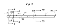
図1および図2を参照すると、操縦可能なガイドシース104は、ハンドル部分102に結合された近位部分114と、遠位部分116と、を含むことができる。遠位部分116は、結合部分120に結合された低デュロメータ非外傷性先端部分118を含むことができ、結合部分120は非外傷性先端118の近くに位置する。いくつかの構成では、非外傷性先端118は、放射線不透過性とすることができる。ガイドシース104の遠位部分116は、結合部分120の近位にあって、以下で詳細に説明するように、ガイドシースの遠位部分の湾曲を調整するために曲がるかつ曲がらない(unflex)ように構成された操縦可能な部分122を含むことができる。
Referring to FIGS. 1 and 2, the
図3~図10は、ガイドシース104の、特に遠位部分116の構造をより詳細に示す。ガイドシース104の湾曲は、1つまたは複数の偏心して位置付けられたプルワイヤによって制御することができる(たとえば、図3、図5、および図8参照)。たとえば、図示した構成では、ガイドシース104は、それぞれのプルワイヤのルーメンまたは導管128、130を通って長手方向に伸びる2つのプルワイヤ124、126を含む。組み立てられたプルワイヤ124、126および導管128、130は、ガイドシースのプルワイヤ導管部分154に配置することができる。図示した構成では、プルワイヤ導管部分154は、少なくとも一部はガイドシースの内側層134の凹部142によって定められる。他の構成が可能であるが、図示した構成では、凹部142は、ガイドシース104の内径D1の内部に及び得る。いくつかの実施形態では、プルワイヤ導管128、130は、プルワイヤが導管内で動くときのプルワイヤ124、126とそれぞれの導管128、130との間の摩擦を低減するために、ポリテトラフルオロエチレン(PTFE)などの滑らかな材料で作ることができる。
3-10 show in more detail the structure of the
プルワイヤ124、126は、結合部分120に埋設されたプルリング144に一方の端部で結合され、ハンドル102の回転ノブ132(図1参照)として構成された制御機構に反対の端部で結合され得る。ノブ132の回転が、プルワイヤ124、126の張力を増減することができ、プルワイヤ124、126の張力が、ガイドシースの湾曲を制御するために、遠位部分116、詳細には操縦可能な部分122が曲がるかつ曲がらないようにすることができる。結合部分122に封入されたプルリング144を示す結合部分の断面図が、図4に示されている。
The
プルリング144およびプルワイヤ124、126の遠位部分は、図5に分離して示されている。図示した構成では、プルリング144は、それの円周のところどころに複数の開口156を定めることができる。ガイドシース104の製造中、結合部分120のポリマー材料は、プルリング144を覆ってリフローされることが可能であり、材料は、図3に示すように、結合部分にプルリングを封入するために開口156を通って流れることができる。さらに、図示の実施形態は2本のプルワイヤ124、126を含むが、他の構成が可能であることを理解されたい。たとえば、ガイドシース104は、デバイスの要件に応じて、単一のプルワイヤ(図12参照)、または3本以上のプルワイヤなど、任意の好適なサイズまたはレイアウトを有する任意の好適な数のプルワイヤを含むことができる。いくつかの構成では、2本のプルワイヤは、詳細には比較的大きい力が必要とされるとき(操縦可能なカテーテル106および埋め込みカテーテル108を搭載したガイドシースを曲げるときなど)、プルリング144に所与の力を伝えるために、単一のより大きいプルワイヤの断面積よりも小さい断面積を占めることができるので、本明細書で説明する特定の実施形態は、2本のプルワイヤを含む。
The distal portions of the
図3~図10を参照すると、ガイドシース104は、ガイドシースの長さに沿って異なる位置に様々な異なる材料を含む複数の層であって、ガイドシースに様々な特性を授けるように構成された、複数の層を含むことができる。たとえば、図3および図6を参照すると、ガイドシース104の操縦可能な部分122は、ガイドシース104の内径D1を定める第1の内側層134と、内側層134の半径方向外側に配置された第2のプルワイヤ導管封入層135と、を含む。第3のらせんコイル状層136が、プルワイヤ導管封入層135の上に広がる。第4の編組層138が、らせんコイル状層136を覆って配置され、第5の外側層140が、編組層を覆って配置され、ガイドシースの外径D2を定める。図6は、ガイドシースの構成を説明するために、外側層140、編組層138、らせんコイル状層136、およびプルワイヤ導管封入層135の各々を一部除去して示したガイドシース104の遠位部分116の平面図を示す。
Referring to FIGS. 3-10, the
第1の層134は、ガイドシース104の全長に沿って広がり、操縦可能な中間カテーテル106がガイドシースのルーメン内でガイドシース104に対してスライドできるように、滑らかな材料(たとえば、PTFE)で作る(またはコーティングする)ことができる。上述のように、第1の層134は、プルワイヤ124、126および導管128、130が収容されるプルワイヤ導管部分154の凹部142を定めることもできる。
The
プルワイヤ導管封入層135は、第1の内側層134とらせんコイル状層136との間に配置することができ、ガイドシースの円周周りに角度方向で変化する厚さを有することができる。たとえば、図8および図9を参照すると、プルワイヤ導管封入層135におけるプルワイヤ導管部分154に近接した部分は、層135がプルワイヤ導管128、130をプルワイヤ導管部分に封入するように、十分に厚くすることができる。一方、プルワイヤ導管封入層135におけるプルワイヤ導管部分154の向かい側の部分は、比較的薄くすることができる。代替として、プルワイヤ導管封入層135は、プルワイヤ導管128、130を含む部分の周り(たとえば、半分)など、ガイドシースの断面の一部分のみの周りに広がることができる。そのような構成では、らせんコイル状層136は、内側層の断面におけるプルワイヤ導管の向かい側にある部分に沿って内側層134に直接触れることができ、プルワイヤ導管封入層が始まる、内側層134の円周に沿った位置で、プルワイヤ導管封入層135を通じて移行することができる。いくつかの実施形態では、プルワイヤ導管封入層135は、様々なポリエーテルブロックアミド(たとえば、Pebax(登録商標))などの任意の好適なポリマーで作ることができる。いくつかの構成では、プルワイヤ導管封入層135は、結合部分120の近位端から、操縦可能な部分122を通って、プルワイヤ出口148(図2)まで広がることができる。
The pullwire
らせんコイル状層136は、たとえば、プルワイヤ導管封入層135または第1の層134の周りにらせん状に巻かれたまたは巻きつけられたワイヤから形成され得る。図示の実施形態では、らせんコイル状層136は、近位のプルリング144付近から結合部分120および操縦可能な部分122を通って、近位部分114と遠位部分116との間にある移行領域146(図1)まで広がることができる。いくつかの実施形態では、らせんコイル状層136が終わる移行領域146は、外側層140が比較的高いデュロメータまたは硬度を有する材料(たとえば、63D Pebax(登録商標))から比較的低いデュロメータを有する材料(たとえば、VESTAMID(登録商標)などのポリアミド)に変わる位置とすることができる。いくつかの実施形態では、シャフトの外側層140または他の層の硬度をそれらの長さに沿って徐々に(たとえば、段階的に)変えると、屈曲中に、または体の血管を通り抜けるときに、シャフトがよじれる、破損する、またはゆがむ可能性を低減することができる。さらに、いくつかの例では、らせんコイル状層136は、たとえば、0.020インチのピッチで1インチ当たり50巻きで巻きつけられたステンレス鋼またはチタンフラットワイヤで作ることができ、ガイドシャフト104の、詳細には操縦可能な部分122の、それが曲げられるときのよじれまたはつぶれに耐えるように構成することができる。
The spiral coiled
編組層138は、らせんコイル状層136の上に広がることができる。図示した構成では、編組層138は、近位のプルリング144近くの結合部分120から、たとえばプルワイヤ出口148まで広がることができる。編組層138は、たとえば、らせんコイル状層136の上に管状の層を形成するためにパターンで編み合わされた金属ワイヤとすることができる。たとえば、図示の実施形態では、編組層138は、オーバー1アンダー1パターン(over 1 under 1 pattern)で編み組まれたステンレス鋼またはチタンフラットワイヤで作られるが、任意の好適な編組パターンを使用することができる。たとえば、別の代表的な実施形態では、編組層138のワイヤは、1インチ当たりのピック数(PPI)が60のピックカウントで1オーバー2、アンダー2パターン(1 over 2, under 2 pattern)で編み組むことができる。編組層138は、たとえば、治療部位で埋め込み物を位置決めするのに役立つことができるトルクをガイドシースが伝えられるように、ガイドシース104の望ましくないねじれ変形に抗うように構成することができる。編組層138は、つぶれまたはよじれ防止特性をガイドシース104に与えることもできる。図示した構成では、結合部分120は、図3および図4に示すように、プルリング144のすぐ下に配置された編組層158を含むこともできる。
The
外側層140は、それの長さに沿って、たとえば、ポリアミド(たとえば、VESTAMID(登録商標))、ポリエーテルブロックアミド(たとえば、Pebax(登録商標))、ナイロン、もしくは任意の他の好適な生体適合性ポリマーなどの様々なポリマー材料のうちのいずれか、またはそれらの組合せを含むことができる。図示した構成では、プルワイヤ導管封入層135、らせんコイル状層136、および編組層138は、ガイドシース104の近位端の遠位で終わることができる。たとえば、いくつかの構成ではこれらの層は、プルワイヤ出口148で終わることができる。プルワイヤ出口148の近位で、外側層140は、図10に示すように、ガイドシースの長さに沿って実質的に均一な外径を維持するために、厚さを増すことができる。
The
図7および図8を参照すると、ガイドシース104の遠位部分116は、圧縮抵抗部分150を含むことができる。図示した構成では、圧縮抵抗部分150は、外側層140に組み込まれ、操縦可能なセクション122のそれぞれの部分を形成する。図7に示すように、圧縮抵抗部分150は、操縦可能な部分122の長さLに沿って広がることができる。圧縮抵抗部分150は、外側層140の断面に沿って円周方向に、もしくは角度方向で広がること、またはそのそれぞれの部分を占めることもできる。たとえば、図8を参照すると、外側層140の断面に沿った圧縮抵抗部分150の角度の範囲は、角度Θで示される。いくつかの実施形態では、角度Θは、10度から180度(または断面の円周の半分)とすることができる。いくつかの実施形態では、角度Θは、10度から90度とすることができる。図8の実施形態では、角度Θは60度である。
Referring to FIGS. 7 and 8, the
いくつかの構成では、圧縮抵抗部分150は、プルワイヤ導管128、130の向かい側に配置することができる。たとえば、図示した構成では、圧縮抵抗部分150は、プルワイヤ導管128、130の直径方向に向かい側に位置するように、プルワイヤ導管部分154から180度だけ角度方向でずれている。この構成では、図8に示すように、プルワイヤ導管部分154を二等分する平面152が、圧縮抵抗部分150もまた二等分する。2本のプルワイヤおよび導管を含む図8の構成では、プルワイヤ導管部分154を二等分する平面152は、それぞれの導管128、130の間を通る。しかしながら、図12に示す代替構成など、単一のプルワイヤを含む構成では、プルワイヤ導管部分154および圧縮抵抗部分150を二等分する平面152が、プルワイヤ160および導管162も二等分するように、単一のプルワイヤ160および導管162が、プルワイヤ導管部分154と同軸上に一直線に並べられ得る。他の構成では、圧縮抵抗部分150は、外側層140の断面に沿って、たとえば必要に応じて90度から180度だけプルワイヤ導管部分154から角度方向でずれていることがある。
In some configurations, the
圧縮抵抗部分150は、圧縮抵抗部分が組み込まれている操縦可能な部分122の外側層140の残りよりも比較的高い硬度またはデュロメータを有する材料から作ることができる。たとえば、いくつかの実施形態では、圧縮抵抗部分150は、操縦可能な部分122の外側層140の残りのデュロメータよりも1.5倍~5倍大きいデュロメータを有することができる。いくつかの実施形態では、圧縮抵抗部分150のデュロメータは、操縦可能な部分122の外側層140の残りのデュロメータよりも2倍~3倍大きいことがある。例示的な実施形態では、圧縮抵抗部分150は、72Dのデュロメータを有するPEBAX(登録商標)から作ることができ、操縦可能な部分122の外側層140の残りは、圧縮抵抗部分150のデュロメータと、操縦可能な部分122の外側層140の残りのデュロメータと、の比が2.9:1であるように、25Dのデュロメータを有するPEBAX(登録商標)から作ることができる。いくつかの実施形態では、圧縮抵抗部分150のデュロメータと操縦可能な部分122の外側層140の残りのデュロメータとの比は、3:1とすることができる。
The
他の実施形態では、圧縮抵抗部分150は、ステンレス鋼、チタン、ニチノールなどのニッケルチタン合金、コバルトクロムなどの金属、または他のポリマーを含む、好適な硬度特性を示す様々な材料のいずれかで作ることができる。さらに、いくつかの構成では、圧縮抵抗部分は、外側層140の全体的な厚さに等しい厚さを有する必要がない。たとえば、圧縮抵抗部分150は、外側層の全体的な厚さよりも小さい厚さを有することができ、必要に応じて外側層内に封入されてもよい。圧縮抵抗部分150のデュロメータは、その長さに沿って変化することもできる。たとえば、圧縮抵抗部分150の近位部分は、遠位部分よりも比較的低いデュロメータを有することができ、その逆も同様である。
In other embodiments, the
圧縮抵抗部分150は、ガイドシース104の操縦可能な部分122に様々な有利な特性を与えることができる。たとえば、圧縮抵抗部分150の比較的より高いデュロメータは、操縦可能な部分122に軸方向の強度を与えることができる。これは、ガイドカテーテルが曲げられるときのガイドシース104の、詳細には操縦可能な部分122の、望ましくない短縮を著しく減らすまたは防止することができる。より詳細には、圧縮抵抗部分150は、ガイドシースが曲げられるときのガイドシースの軸方向の圧縮、および材料の関連したしわを、ガイドシースが撓んでいない状態であるときに比べて減らすことができる。材料のそのような軸方向の圧縮およびしわは、材料が変形するとき、ガイドシースの長さを縮小することがあり、ガイドシースを損傷させることがある。ガイドシース104が曲げられるときのガイドシースの短縮を減らすことまたは無くすことによって、圧縮抵抗部分150は、ガイドシースを曲げた後に治療部位で埋め込み物の所望の位置を獲得または回復するために、操作者が(たとえば、患者の脈管を通って送達装置を前進または後退させることによって)送達装置を長手方向に再位置決めする必要を減らすことができる。
The
さらに、プルワイヤ導管128、130から角度方向でずれた圧縮抵抗部分150の位置は、指定された方向でガイドシースの操縦可能な部分122の変形を開始するのに役立つことができる。たとえば、圧縮抵抗部分150がプルワイヤ導管128、130の向かい側に位置するとき、圧縮抵抗部分の軸方向の剛性は、図11に示すように、ガイドシースが曲げられるとき、圧縮抵抗部分から離れる方向に操縦可能な部分122の撓みを誘起することができる。圧縮抵抗部分150は、特に1つまたは複数の構成層(たとえば、内側層134などのPTFE層)が周囲の層に強力に接着されていない場合に、シースが曲げられるとき、シースの異なる層の互いに対する長手方向の動きを減らすことによって、ガイドシースが楕円形になること(「パンケーキ状になる」とも呼ばれる)を減らすまたは防ぐこともできる。
In addition, the position of the
圧縮抵抗部分150は、ガイドシースを破損することなくプルワイヤ124、126によって遠位部分に加えられる所与の力に対して到達可能な遠位部分116の屈曲の度合いを増やすこともできる。遠位部分116の屈曲の角度はαで表され、図11に示される。たとえば、ガイドシース104の短縮を減らすことによって、プルワイヤ124、126によってかけられる力のより大きい割合を、ガイドシースを弾性的に圧縮するのではなくガイドシースを曲げるために利用できる。さらに、圧縮抵抗部分150は、ガイドシース104が曲げられるとき、ガイドシース104の短縮に伴ってプルワイヤ124、126が緩むのを減らすまたは防ぐことができ、一般的なガイドシースと比較して、所与のプルワイヤ移動により大きい湾曲の度合いが達成可能となる。本明細書で使用する「プルワイヤ移動」という用語は、プルワイヤに張力がかけられるとき、プルワイヤの長さ沿いの所与の点が静止基準(たとえば、プルワイヤ導管)に対して移動する直線距離を指す。
The
さらに、圧縮抵抗部分150は、上記で説明したらせんコイル状層136、および編組層138とともに、著しく相乗的な利点をもたらすことができ、知られている操縦可能なシースおよびカテーテルを超えてガイドシース104の性能を向上させる。たとえば、22Frの内径を有し、圧縮抵抗部分、らせんコイル状層、および編組層の特徴を含む、搭載されていないガイドシース(たとえば、送達カテーテルまたは他のシャフトがそれのルーメンから伸びていないガイドシース)の遠位部分は、プルワイヤによってかけられた175Nの力により、よじれることなく、かつ著しく短縮することなく、355度近く曲がることができる。この例では、ガイドシースの遠位部分に175Nの力をかけるために、50mmのプルワイヤ移動が必要であった。対照的に、圧縮抵抗部分がなく、それのルーメンから送達カテーテルまたは他のシースが伸びていない一般的な操縦可能なカテーテルデバイスの場合、175Nの力が270度の屈曲を作り出し、60mmのプルワイヤ移動を必要とし、ガイドシースは、6mm~10mm短縮すると予想され得る。
In addition, the
別の例では、22Frの内径を有し、上記の圧縮抵抗部分、らせんコイル状層、および編組層の特徴を含み、送達カテーテルおよび埋め込みカテーテルがガイドシースのルーメン内に同軸方向に伸びて搭載された、ガイドシースの遠位部分は、プルワイヤによってかけられた250Nの力により、よじれることなく、かつ著しく短縮することなく、270度曲がることができた。この例では、ガイドシースの遠位部分に250Nの力をかけるために、40mmのプルワイヤ移動が必要であった。対照的に、圧縮抵抗部分がなく、送達カテーテルまたは埋め込みカテーテルが搭載された操縦可能なカテーテルデバイスの場合、250Nの力が180度の屈曲を作り出し、70mmのプルワイヤ移動を必要とし、ガイドシースは、6mm~10mm短縮すると予想され得る。 In another example, it has an inner diameter of 22 Fr and includes the characteristics of the compression resistance portion, the spiral coiled layer, and the braided layer described above, and the delivery catheter and the implantable catheter are mounted coaxially within the lumen of the guide sheath. In addition, the distal portion of the guide sheath was able to bend 270 degrees without kinking and without significant shortening due to the force of 250N applied by the pull wire. In this example, a 40 mm pullwire movement was required to apply a force of 250 N to the distal portion of the guide sheath. In contrast, in the case of a maneuverable catheter device with no compression resistance portion and equipped with a delivery catheter or implantable catheter, a force of 250 N creates a 180 degree bend and requires 70 mm pullwire movement, the guide sheath It can be expected to be shortened by 6 mm to 10 mm.
使用において、送達装置100は、任意の知られている送達技法を使用して患者の脈管構造を通して導入され、進められ得る。経大腿手技では、送達装置は、大腿動脈および大動脈を通して心臓まで挿入され得る(限定はしないが、一般的に、大動脈弁置換に使用される)。経中隔手技(一般的に、大動脈または僧帽弁置換に使用される)では、送達デバイスは、大腿静脈を通し、右心室と左心室とを分けている中隔を通すなどして、右心房に進めることができる。開示する実施形態は、ガイドシース104のトルク伝達性(torqueability)および遠位部分116で達成できる湾曲の度合いが比較的高いことにより、いくつかの手法において送達装置が僧帽弁にアクセスするために辿らなければならない曲がりくねった経路にもかかわらず標的部位での人工弁の正確な位置決めが可能になるので、人工弁を自然僧帽弁に送り届けるのに特に有用であり得る。経心室手技では、送達装置は、下側前方心室壁上のベアスポットで行われる外科的切開によって挿入され得る(限定はしないが、一般的に、大動脈または僧帽弁置換に使用される)。経心房手技では、送達装置は、左または右心房の壁に行われる外科的切開によって挿入され得る。経大動脈手技では、送達装置は、上行大動脈に行われる外科的切開によって挿入され、心臓に向かって進められ得る(限定はしないが、一般的に、大動脈弁置換に使用される)。
In use, the
これらの手技のいくつかにおいて、圧縮抵抗部分150、らせんコイル状層136、および編組層138の組合せは、治療部位で、心臓弁110などの人工器官デバイスを正確に位置決めするのに役立ち得る。たとえば、僧帽弁にアクセスするための経中隔手技では、送達装置の遠位端が治療部位に進められた後、ガイドシース104の遠位部分116は、人工弁110を僧帽弁と軸方向に位置合わせするために(たとえば、いくつかの例では180度以上)曲げられ得る。遠位部分116が曲げられた状態である間、ガイドシース104は、僧帽弁に対して人工弁110を半径方向に位置決めするためにトルクを与えることもできる。圧縮抵抗部分150、らせんコイル状層136、および編組層138の組合せは、ガイドシースが著しい短縮またはよじれなしで曲がること、およびシャフトの望ましくないねじり変形またはガイドシースの関連する予測不能な回転運動なしでトルクを与えられることを可能にすることができる。
In some of these procedures, the combination of
代替構成では、開示する送達装置実施形態の構成要素は、開示の趣旨から逸脱することなく並べ替えられ得ることを理解されたい。たとえば、らせんコイル状層136および編組層138の位置は、らせんコイル状層が編組層の上になるように逆にされ得る。代替として、らせんコイル状層136および編組層138は、1つまたは複数の中間層によって互いから分離されていることがある。さらに、圧縮抵抗部分150は、外側層140のそれぞれの部分である必要はなく、ガイドシース104の任意の好適な層に組み込まれ得る。圧縮抵抗部分150はまた、操縦可能な部分122の長さ全体に沿って広がる必要はなく、操縦可能な部分の任意の好適な部分に沿って広がることができる。本明細書で説明する、開示する圧縮抵抗部分、らせんコイル状層、および編組層の特徴は、送達カテーテルなど、他のタイプの操縦可能なカテーテルデバイスにも適用可能であり得る。
It should be understood that in alternative configurations, the components of the disclosed delivery device embodiment may be rearranged without departing from the spirit of the disclosure. For example, the positions of the spiral coiled
全般的考察
この説明の目的で、本開示の実施形態のいくつかの態様、利点、および新規の特徴について、本明細書で説明する。開示する方法、装置、およびシステムは、決して限定的なものと解釈されるべきではない。代わりに、本開示は、様々な開示する実施形態の新規かつ非自明な特徴および態様すべてを、単独でかつ互いとの様々な組合せおよび部分的組合せで対象とする。方法、装置、およびシステムは、いずれか特定の態様または特徴またはそれらの組合せに限定されず、開示する実施形態は、いずれか1つまたは複数の特定の利点があること、または問題が解決されることを必要としない。
General Discussion For the purposes of this description, some aspects, advantages, and novel features of embodiments of the present disclosure are described herein. The disclosed methods, devices, and systems should by no means be construed as limiting. Instead, the present disclosure covers all novel and non-trivial features and embodiments of the various disclosed embodiments, alone and in various combinations and partial combinations with each other. The methods, devices, and systems are not limited to any particular embodiment or feature or combination thereof, and the disclosed embodiments have one or more specific advantages, or the problem is solved. I don't need that.
開示する実施形態のいくつかの動作を、提示の便宜上、特定の連続した順序で説明するが、以下に記載する特殊な文言によって特定の順序が必要とされない限り、この説明の仕方は再配置を含むことを理解されたい。たとえば、連続して説明する動作は、場合によっては、再編成されるかまたは同時に行われることがある。さらに、簡単のために、添付図は、開示する方法が他の方法に関連して使用され得る様々な方法を示さない場合がある。加えて、説明は、開示する方法を説明するために「提供する」または「実現する」のような用語を使用することがある。これらの用語は、行われる実際の動作の高水準抽象概念である。これらの用語に対応する実際の動作は、特定の実装形態に応じて変わる可能性があり、当業者によって容易に識別可能である。 Some of the actions of the disclosed embodiments are described in a particular contiguous order for convenience of presentation, but this method of description repositions unless a particular order is required by the special language described below. Please understand that it includes. For example, the actions described in succession may be reorganized or performed simultaneously, in some cases. Further, for simplicity, the attached figures may not indicate the various methods in which the disclosed method may be used in connection with other methods. In addition, the description may use terms such as "provide" or "realize" to describe the method of disclosure. These terms are high-level abstractions of the actual action taken. The actual behavior corresponding to these terms may vary depending on the particular implementation and is easily identifiable by one of ordinary skill in the art.
本明細書で、および特許請求の範囲で使用する単数形「a」、「an」、および「the」は、文脈上明確に別段の定めがない限り複数形を含む。加えて、「含む」という用語は、「備える」を意味する。さらに、「結合される」および「関連する」という用語は、電気的に、電磁的に、または物理的に(たとえば、機械的にもしくは化学的に)結合またはリンクされる意味であり、特殊の反対の文言がなければ、結合されるかまたは関連する部材間に中間の要素の存在を排除しない。 As used herein and in the claims, the singular forms "a," "an," and "the" include the plural unless expressly specified in the context. In addition, the term "contains" means "prepare." In addition, the terms "bonded" and "related" mean electrically, electromagnetically, or physically (eg, mechanically or chemically) bonded or linked, and are special. Without the opposite wording, it does not rule out the presence of intermediate elements between members that are combined or related.
本出願との関連では、「下側」および「上側」という用語は、それぞれ「流入」および「流出」という用語と区別なく使用される。したがって、たとえば、弁の下側端部は、それの流入端部であり、弁の上側端部は、それの流出端部である。 In the context of this application, the terms "lower" and "upper" are used interchangeably with the terms "inflow" and "outflow", respectively. Thus, for example, the lower end of the valve is its inflow end and the upper end of the valve is its outflow end.
本明細書で使用する、「近位」という用語は、使用者により近く、埋め込み部位からより遠いデバイスの位置、方向、または部分を指す。本明細書で使用する、「遠位」という用語は、使用者からより遠く、埋め込み部位により近い装置の位置、方向、または部分を指す。したがって、たとえば、装置の近位動作は、使用者に向かう装置の動きであり、装置の遠位動作は、使用者から離れる装置の動きである。「長手方向」および「軸方向」という用語は、明確に別段の定めがない限り、軸が近位および遠位方向に延びることを指す。 As used herein, the term "proximal" refers to the location, orientation, or location of a device that is closer to the user and farther from the implantation site. As used herein, the term "distal" refers to the location, orientation, or portion of the device that is farther from the user and closer to the implantation site. Thus, for example, the proximal movement of the device is the movement of the device towards the user and the distal movement of the device is the movement of the device away from the user. The terms "longitudinal" and "axial" refer to the axis extending proximally and distally, unless expressly specified otherwise.
別段に規定されていない限り、本明細書または特許請求の範囲において使用される、構成要素の量、距離、力、比、角度、パーセンテージなどを表す数はすべて、「約」という用語で修飾されるものと理解されたい。したがって、暗黙的または明示的に、別段に規定されていない限り、記載される数値パラメータは、求められる所望の特性および/または当業者によく知られているテスト条件/方法のもとでの検出の限界によって決まる可能性がある近似値である。考察した従来技術と実施形態とを直接的および明示的に区別するとき、実施形態数は、「約」という語が記載されていない限り近似値ではない。さらに、本明細書に記載する代替形態すべてが同等であるとは限らない。 Unless otherwise specified, any number representing the quantity, distance, force, ratio, angle, percentage, etc. of a component as used herein or in the claims is modified by the term "about". Please understand that. Thus, implicitly or explicitly, unless otherwise specified, the numerical parameters described are detected under the desired characteristics and / or test conditions / methods well known to those of skill in the art. It is an approximate value that may be determined by the limit of. When making a direct and explicit distinction between the prior art and embodiments considered, the number of embodiments is not an approximation unless the word "about" is mentioned. Moreover, not all alternative forms described herein are equivalent.
開示した技術の原理を適用することができる多くの可能な実施形態に鑑みて、図示の実施形態は、好ましい例にすぎず、本開示の範囲を限定すると受け取られるべきではないことを認識されたい。むしろ、本開示の範囲は、少なくとも以下の特許請求の範囲と同じである。
[付記項1]
近位部分、遠位部分、およびプルワイヤ導管を備える操縦可能なシャフトであって、前記プルワイヤ導管が、少なくとも部分的に前記シャフトの前記近位部分および前記遠位部分を通って伸びる、操縦可能なシャフトと、
前記プルワイヤ導管を通って伸び、近位端部分および遠位端部分を有するプルワイヤであって、前記プルワイヤの前記遠位端部分が、前記シャフトの前記遠位部分に固定される、プルワイヤと、
前記プルワイヤの前記近位端部分に動作可能に接続され、前記シャフトの前記遠位部分の湾曲を調整するために前記プルワイヤの張力を増減するように構成された調整機構と、を備える送達装置であって、
前記シャフトの前記遠位部分が、結合部分と、前記結合部分の近位にある操縦可能な部分と、前記結合部分に埋設されかつ前記プルワイヤの前記遠位端部分に結合されたプルリングと、を備え、前記操縦可能な部分が、1つまたは複数の層を有し、かつ前記操縦可能な部分の外側層に組み込まれる圧縮抵抗部分と編組層とを含み、前記外側層が、第1の硬度を有し、前記圧縮抵抗部分が、前記第1の硬度よりも大きい第2の硬度を有し、前記編組層が、前記操縦可能な部分に沿って前記プルリングの近くの前記結合部分から近位に広がる、送達装置。
[付記項2]
前記圧縮抵抗部分が、前記プルワイヤ導管の向かい側に位置している、付記項1に記載の送達装置。
[付記項3]
前記圧縮抵抗部分が、前記外側層の前記断面に沿って10度~180度広がる、付記項1または付記項2に記載の送達装置。
[付記項4]
前記圧縮抵抗部分が、前記外側層の前記断面に沿って60度広がる、付記項3に記載の送達装置。
[付記項5]
前記シャフトが、前記シャフトの内径を定める内側層を備え
る、付記項1から4のいずれか一項に記載の送達装置。
[付記項6]
前記シャフトが、前記内側層と前記外側層との間にらせんコイル状層をさらに備える、付記項5に記載の送達装置。
[付記項7]
前記編組層が、前記らせんコイル状層の少なくとも一部を覆って編組される、付記項6に記載の送達装置。
[付記項8]
前記シャフトが、前記内側層と前記らせんコイル状層との間に、前記プルワイヤ導管を封入するプルワイヤ導管封入層をさらに備える、付記項7に記載の送達装置。
[付記項9]
前記内側層が、前記プルワイヤ導管を収容するように構成された凹部を画定する、付記項5に記載の送達装置。
[付記項10]
前記プルワイヤが第1のプルワイヤであり、
前記プルワイヤ導管が第1のプルワイヤ導管であり、
前記シャフトが、前記凹部に前記第1のプルワイヤ導管に隣接して配置された第2のプルワイヤ導管に収容された第2のプルワイヤをさらに備える、
付記項9に記載の送達装置。
[付記項11]
前記第2の硬度と前記第1の硬度との比が、1.5:1~5:1である、付記項1から10のいずれか一項に記載の送達装置。
[付記項12]
前記比が3:1である、付記項11に記載の送達装置。
[付記項13]
前記シャフトがガイドシースであり、前記送達装置が、前記ガイドシース内に同軸上に配置された埋め込みカテーテルをさらに含み、前記埋め込みカテーテルの遠位端に取り付けられた人工弁を含む、付記項1から12のいずれか一項に記載の送達装置。
It should be noted that in view of the many possible embodiments to which the disclosed technical principles can be applied, the illustrated embodiments are only preferred examples and should not be taken to limit the scope of the present disclosure. .. Rather, the scope of the present disclosure is at least the same as the following claims.
[Appendix 1]
A maneuverable shaft comprising a proximal portion, a distal portion, and a pullwire duct, wherein the pullwire conduit extends at least partially through the proximal portion and the distal portion of the shaft. With the shaft
A pull wire that extends through the pull wire duct and has a proximal end portion and a distal end portion, wherein the distal end portion of the pull wire is secured to the distal portion of the shaft.
A delivery device comprising an adjustment mechanism operably connected to the proximal end portion of the pull wire and configured to increase or decrease the tension of the pull wire to adjust the curvature of the distal portion of the shaft. There,
The distal portion of the shaft comprises a coupling portion, a maneuverable portion proximal to the coupling portion, and a pull ring embedded in the coupling portion and coupled to the distal end portion of the pull wire. The steerable portion comprises one or more layers and includes a compression resistance portion and a braided layer incorporated into the outer layer of the steerable portion, wherein the outer layer has a first hardness. The compression resistance portion has a second hardness greater than the first hardness, and the braided layer is proximal to the coupling portion near the pull ring along the maneuverable portion. A delivery device that spreads to.
[Appendix 2]
The delivery device according to Supplementary Item 1, wherein the compression resistance portion is located opposite the pull wire conduit.
[Appendix 3]
The delivery device according to annex 1 or 2, wherein the compression resistance portion spreads by 10 to 180 degrees along the cross section of the outer layer.
[Appendix 4]
The delivery device according to Supplementary Item 3, wherein the compression resistance portion spreads by 60 degrees along the cross section of the outer layer.
[Appendix 5]
The shaft comprises an inner layer that determines the inner diameter of the shaft.
The delivery device according to any one of Supplementary Items 1 to 4.
[Appendix 6]
5. The delivery device according to Appendix 5, wherein the shaft further comprises a spiral coiled layer between the inner layer and the outer layer.
[Appendix 7]
The delivery device according to Supplementary Item 6, wherein the braided layer is braided so as to cover at least a part of the spiral coiled layer.
[Appendix 8]
7. The delivery device according to Appendix 7, wherein the shaft further comprises a pullwire conduit encapsulation layer that encapsulates the pullwire conduit between the inner layer and the spiral coiled layer.
[Appendix 9]
The delivery device according to Appendix 5, wherein the inner layer defines a recess configured to accommodate the pullwire conduit.
[Appendix 10]
The pull wire is the first pull wire.
The pull wire conduit is the first pull wire conduit and
The shaft further comprises a second pull wire housed in a second pull wire conduit disposed in the recess adjacent to the first pull wire conduit.
The delivery device according to Appendix 9.
[Appendix 11]
The delivery device according to any one of Supplementary Items 1 to 10, wherein the ratio of the second hardness to the first hardness is 1.5: 1 to 5: 1.
[Appendix 12]
11. The delivery device according to Appendix 11, wherein the ratio is 3: 1.
[Appendix 13]
From Appendix 1, wherein the shaft is a guide sheath, the delivery device further comprises an implantable catheter coaxially disposed within the guide sheath, and an artificial valve attached to the distal end of the implantable catheter. 12. The delivery device according to any one of paragraphs 12.
100 送達装置
102 ハンドル部分
104 ガイドシース
106 操縦可能なカテーテル
108 埋め込みカテーテル
110 人工器官デバイス
112 膨張可能バルーン
114 近位部分
116 遠位部分
118 非外傷性先端部分
120 結合部分
122 操縦可能な部分
124 プルワイヤ
126 プルワイヤ
128 導管
130 導管
132 回転ノブ
134 内側層
135 プルワイヤ導管封入層
136 らせんコイル状層
138 編組層
140 外側層
142 凹部
144 プルリング
146 移行領域
148 プルワイヤ出口
150 圧縮抵抗部分
152 平面
154 プルワイヤ導管部分
156 開口
158 編組層
160 プルワイヤ
162 導管
100
Claims (17)
前記プルワイヤ導管を通って伸び、近位端部分および遠位端部分を有するプルワイヤであって、前記プルワイヤの前記遠位端部分が、前記シャフトの前記遠位部分に固定される、プルワイヤと、
前記プルワイヤの前記近位端部分に動作可能に接続され、前記シャフトの前記遠位部分の湾曲を調整するために前記プルワイヤの張力を増減するように構成された調整機構と、を備える送達装置であって、
前記シャフトの前記遠位部分が、
結合部分と、
前記結合部分の近位にある操縦可能な部分と、
前記結合部分に埋設されかつ前記プルワイヤの前記遠位端部分に結合されたプルリングと、
を備え、
前記操縦可能な部分が、
1つまたは複数の層を有し、かつ
前記操縦可能な部分の1つまたは複数の層のうちの1つの層に組み込まれる圧縮抵抗部分を含み、
前記圧縮抵抗部分が、前記プルリングから間隔を空けて近位にありかつ前記層の断面の一部に沿って角度方向に広がり、
前記圧縮抵抗部分が組み込まれている前記操縦可能な部分の前記層が、第1の硬度を有し、
前記圧縮抵抗部分が、前記第1の硬度よりも大きい第2の硬度を有する、送達装置。 A maneuverable shaft comprising a proximal portion, a distal portion, and a pullwire duct, wherein the pullwire conduit extends at least partially through the proximal portion and the distal portion of the shaft. With the shaft
A pull wire that extends through the pull wire duct and has a proximal end portion and a distal end portion, wherein the distal end portion of the pull wire is secured to the distal portion of the shaft.
A delivery device comprising an adjustment mechanism operably connected to the proximal end portion of the pull wire and configured to increase or decrease the tension of the pull wire to adjust the curvature of the distal portion of the shaft. There,
The distal portion of the shaft
With the joint part,
A maneuverable part proximal to the joint and
With a pull ring embedded in the joint and coupled to the distal end of the pull wire,
Equipped with
The maneuverable part
Has one or more layers and
Containing a compression resistance portion incorporated into one layer of one or more layers of said maneuverable portion.
The compression resistance portion is proximal to the pull ring and extends angularly along a portion of the cross section of the layer.
The layer of the maneuverable portion in which the compression resistance portion is incorporated has a first hardness.
A delivery device in which the compression resistance portion has a second hardness higher than the first hardness.
前記圧縮抵抗部分が組み込まれている前記層が、前記シャフトの外径を定める外側層である、請求項1から4のいずれか一項に記載の送達装置。 The shaft comprises an inner layer that defines the inner diameter of the shaft.
The delivery device according to any one of claims 1 to 4, wherein the layer in which the compression resistance portion is incorporated is an outer layer that determines the outer diameter of the shaft.
前記プルワイヤ導管が第1のプルワイヤ導管であり、
前記シャフトが、前記凹部に前記第1のプルワイヤ導管に隣接して配置された第2のプルワイヤ導管に収容された第2のプルワイヤをさらに備える、
請求項9に記載の送達装置。 The pull wire is the first pull wire.
The pull wire conduit is the first pull wire conduit and
The shaft further comprises a second pull wire housed in a second pull wire conduit disposed in the recess adjacent to the first pull wire conduit.
The delivery device according to claim 9.
前記プルワイヤ導管を通って伸び、近位端部分および遠位端部分を有するプルワイヤであって、前記プルワイヤの前記遠位端部分が、前記シャフトの前記遠位部分に固定される、プルワイヤと、
前記プルワイヤの前記近位端部分に動作可能に接続され、前記シャフトの前記遠位部分の湾曲を調整するために前記プルワイヤの張力を増減するように構成された調整機構と、を備える送達装置であって、
前記シャフトの前記遠位部分が、1つまたは複数の層と、プルリングと、前記遠位部分の1つまたは複数の層のうちの1つの層に組み込まれかつ前記プルリングから間隔を空けて近位にある圧縮抵抗部分と、を備え、
前記圧縮抵抗部分が、前記層の断面の一部に沿って角度方向に広がり、前記圧縮抵抗部分が組み込まれている前記層の硬度よりも大きい硬度を有し、前記圧縮抵抗部分が、前記層の前記断面に沿って前記プルワイヤ導管から角度方向でずれている、送達装置。 A maneuverable shaft comprising a proximal portion, a distal portion, and a pullwire duct, wherein the pullwire conduit extends at least partially through the proximal portion and the distal portion of the shaft. With the shaft
A pull wire that extends through the pull wire duct and has a proximal end portion and a distal end portion, wherein the distal end portion of the pull wire is secured to the distal portion of the shaft.
A delivery device comprising an adjustment mechanism operably connected to the proximal end portion of the pull wire and configured to increase or decrease the tension of the pull wire to adjust the curvature of the distal portion of the shaft. There,
The distal portion of the shaft is integrated into one or more layers, a pull ring and one of one or more layers of the distal portion and is proximal to the pull ring. With the compression resistance part in
The compression resistance portion extends in an angular direction along a part of the cross section of the layer and has a hardness higher than the hardness of the layer in which the compression resistance portion is incorporated, and the compression resistance portion is the layer. A delivery device that is angularly offset from the pullwire conduit along the cross section of the.
Priority Applications (1)
| Application Number | Priority Date | Filing Date | Title |
|---|---|---|---|
| JP2022007892A JP7278437B2 (en) | 2016-11-07 | 2022-01-21 | Device for introducing and manipulating multiple telescoping catheters |
Applications Claiming Priority (5)
| Application Number | Priority Date | Filing Date | Title |
|---|---|---|---|
| US201662418528P | 2016-11-07 | 2016-11-07 | |
| US62/418,528 | 2016-11-07 | ||
| US15/796,436 | 2017-10-27 | ||
| US15/796,436 US10653862B2 (en) | 2016-11-07 | 2017-10-27 | Apparatus for the introduction and manipulation of multiple telescoping catheters |
| PCT/US2017/060336 WO2018085812A1 (en) | 2016-11-07 | 2017-11-07 | Apparatus for the introduction and manipulation of multiple telescoping catheters |
Related Child Applications (1)
| Application Number | Title | Priority Date | Filing Date |
|---|---|---|---|
| JP2022007892A Division JP7278437B2 (en) | 2016-11-07 | 2022-01-21 | Device for introducing and manipulating multiple telescoping catheters |
Publications (3)
| Publication Number | Publication Date |
|---|---|
| JP2019532767A JP2019532767A (en) | 2019-11-14 |
| JP2019532767A5 JP2019532767A5 (en) | 2020-12-17 |
| JP7015831B2 true JP7015831B2 (en) | 2022-02-03 |
Family
ID=62065913
Family Applications (2)
| Application Number | Title | Priority Date | Filing Date |
|---|---|---|---|
| JP2019522998A Active JP7015831B2 (en) | 2016-11-07 | 2017-11-07 | Equipment for the introduction and operation of multiple telescopic catheters |
| JP2022007892A Active JP7278437B2 (en) | 2016-11-07 | 2022-01-21 | Device for introducing and manipulating multiple telescoping catheters |
Family Applications After (1)
| Application Number | Title | Priority Date | Filing Date |
|---|---|---|---|
| JP2022007892A Active JP7278437B2 (en) | 2016-11-07 | 2022-01-21 | Device for introducing and manipulating multiple telescoping catheters |
Country Status (5)
| Country | Link |
|---|---|
| US (3) | US10653862B2 (en) |
| EP (2) | EP3535010B1 (en) |
| JP (2) | JP7015831B2 (en) |
| CN (1) | CN109906099A (en) |
| WO (1) | WO2018085812A1 (en) |
Families Citing this family (66)
| Publication number | Priority date | Publication date | Assignee | Title |
|---|---|---|---|---|
| US8652202B2 (en) | 2008-08-22 | 2014-02-18 | Edwards Lifesciences Corporation | Prosthetic heart valve and delivery apparatus |
| US8449599B2 (en) | 2009-12-04 | 2013-05-28 | Edwards Lifesciences Corporation | Prosthetic valve for replacing mitral valve |
| US8579964B2 (en) | 2010-05-05 | 2013-11-12 | Neovasc Inc. | Transcatheter mitral valve prosthesis |
| US9308087B2 (en) | 2011-04-28 | 2016-04-12 | Neovasc Tiara Inc. | Sequentially deployed transcatheter mitral valve prosthesis |
| US9554897B2 (en) | 2011-04-28 | 2017-01-31 | Neovasc Tiara Inc. | Methods and apparatus for engaging a valve prosthesis with tissue |
| US9345573B2 (en) | 2012-05-30 | 2016-05-24 | Neovasc Tiara Inc. | Methods and apparatus for loading a prosthesis onto a delivery system |
| US9572665B2 (en) | 2013-04-04 | 2017-02-21 | Neovasc Tiara Inc. | Methods and apparatus for delivering a prosthetic valve to a beating heart |
| WO2016090308A1 (en) | 2014-12-04 | 2016-06-09 | Edwards Lifesciences Corporation | Percutaneous clip for repairing a heart valve |
| CN110433010A (en) | 2015-05-14 | 2019-11-12 | 爱德华兹生命科学公司 | Heart valve sealing device and its delivery apparatus |
| CN113633435A (en) | 2016-01-29 | 2021-11-12 | 内奥瓦斯克迪亚拉公司 | Prosthetic valve for preventing outflow obstruction |
| US10799676B2 (en) | 2016-03-21 | 2020-10-13 | Edwards Lifesciences Corporation | Multi-direction steerable handles for steering catheters |
| US11219746B2 (en) | 2016-03-21 | 2022-01-11 | Edwards Lifesciences Corporation | Multi-direction steerable handles for steering catheters |
| US10799677B2 (en) | 2016-03-21 | 2020-10-13 | Edwards Lifesciences Corporation | Multi-direction steerable handles for steering catheters |
| US10835714B2 (en) | 2016-03-21 | 2020-11-17 | Edwards Lifesciences Corporation | Multi-direction steerable handles for steering catheters |
| US10799675B2 (en) | 2016-03-21 | 2020-10-13 | Edwards Lifesciences Corporation | Cam controlled multi-direction steerable handles |
| US10973638B2 (en) | 2016-07-07 | 2021-04-13 | Edwards Lifesciences Corporation | Device and method for treating vascular insufficiency |
| US10653862B2 (en) * | 2016-11-07 | 2020-05-19 | Edwards Lifesciences Corporation | Apparatus for the introduction and manipulation of multiple telescoping catheters |
| CN113893064A (en) | 2016-11-21 | 2022-01-07 | 内奥瓦斯克迪亚拉公司 | Methods and systems for rapid retrieval of transcatheter heart valve delivery systems |
| US10905554B2 (en) | 2017-01-05 | 2021-02-02 | Edwards Lifesciences Corporation | Heart valve coaptation device |
| LT3558169T (en) | 2017-04-18 | 2022-02-10 | Edwards Lifesciences Corporation | Heart valve sealing devices and delivery devices therefor |
| US11224511B2 (en) | 2017-04-18 | 2022-01-18 | Edwards Lifesciences Corporation | Heart valve sealing devices and delivery devices therefor |
| US10799312B2 (en) | 2017-04-28 | 2020-10-13 | Edwards Lifesciences Corporation | Medical device stabilizing apparatus and method of use |
| US10959846B2 (en) | 2017-05-10 | 2021-03-30 | Edwards Lifesciences Corporation | Mitral valve spacer device |
| CA3073834A1 (en) | 2017-08-25 | 2019-02-28 | Neovasc Tiara Inc. | Sequentially deployed transcatheter mitral valve prosthesis |
| US11051940B2 (en) | 2017-09-07 | 2021-07-06 | Edwards Lifesciences Corporation | Prosthetic spacer device for heart valve |
| US11065117B2 (en) | 2017-09-08 | 2021-07-20 | Edwards Lifesciences Corporation | Axisymmetric adjustable device for treating mitral regurgitation |
| US11040174B2 (en) | 2017-09-19 | 2021-06-22 | Edwards Lifesciences Corporation | Multi-direction steerable handles for steering catheters |
| US10973639B2 (en) | 2018-01-09 | 2021-04-13 | Edwards Lifesciences Corporation | Native valve repair devices and procedures |
| US10245144B1 (en) | 2018-01-09 | 2019-04-02 | Edwards Lifesciences Corporation | Native valve repair devices and procedures |
| US10076415B1 (en) | 2018-01-09 | 2018-09-18 | Edwards Lifesciences Corporation | Native valve repair devices and procedures |
| US10238493B1 (en) | 2018-01-09 | 2019-03-26 | Edwards Lifesciences Corporation | Native valve repair devices and procedures |
| US10111751B1 (en) | 2018-01-09 | 2018-10-30 | Edwards Lifesciences Corporation | Native valve repair devices and procedures |
| US10123873B1 (en) | 2018-01-09 | 2018-11-13 | Edwards Lifesciences Corporation | Native valve repair devices and procedures |
| US10231837B1 (en) | 2018-01-09 | 2019-03-19 | Edwards Lifesciences Corporation | Native valve repair devices and procedures |
| US10136993B1 (en) | 2018-01-09 | 2018-11-27 | Edwards Lifesciences Corporation | Native valve repair devices and procedures |
| US10507109B2 (en) | 2018-01-09 | 2019-12-17 | Edwards Lifesciences Corporation | Native valve repair devices and procedures |
| US10159570B1 (en) | 2018-01-09 | 2018-12-25 | Edwards Lifesciences Corporation | Native valve repair devices and procedures |
| SG11202006509SA (en) | 2018-01-09 | 2020-08-28 | Edwards Lifesciences Corp | Native valve repair devices and procedures |
| WO2019147504A1 (en) * | 2018-01-25 | 2019-08-01 | Cephea Valve Technologies, Inc. | Cardiac valve delivery devices and systems |
| US11389297B2 (en) | 2018-04-12 | 2022-07-19 | Edwards Lifesciences Corporation | Mitral valve spacer device |
| US11207181B2 (en) | 2018-04-18 | 2021-12-28 | Edwards Lifesciences Corporation | Heart valve sealing devices and delivery devices therefor |
| US10953195B2 (en) | 2018-06-01 | 2021-03-23 | Covidien Lp | Flexible tip catheter |
| CN110575285A (en) * | 2018-06-08 | 2019-12-17 | 上海微创心通医疗科技有限公司 | Implant delivery tube and implant delivery system |
| US10945844B2 (en) | 2018-10-10 | 2021-03-16 | Edwards Lifesciences Corporation | Heart valve sealing devices and delivery devices therefor |
| AU2019374743B2 (en) | 2018-11-08 | 2022-03-03 | Neovasc Tiara Inc. | Ventricular deployment of a transcatheter mitral valve prosthesis |
| EP4223258A1 (en) | 2019-02-14 | 2023-08-09 | Edwards Lifesciences Corporation | Heart valve sealing devices and delivery devices therefor |
| US11602429B2 (en) | 2019-04-01 | 2023-03-14 | Neovasc Tiara Inc. | Controllably deployable prosthetic valve |
| WO2020210652A1 (en) | 2019-04-10 | 2020-10-15 | Neovasc Tiara Inc. | Prosthetic valve with natural blood flow |
| CA3140925A1 (en) | 2019-05-20 | 2020-11-26 | Neovasc Tiara Inc. | Introducer with hemostasis mechanism |
| AU2020295566B2 (en) | 2019-06-20 | 2023-07-20 | Neovasc Tiara Inc. | Low profile prosthetic mitral valve |
| EP3993736B1 (en) | 2019-07-02 | 2023-11-15 | Edwards Lifesciences Corporation | Prosthetic heart valve and delivery apparatus therefor |
| US11524139B2 (en) | 2019-07-15 | 2022-12-13 | Medtronic, Inc. | Catheter with active return curve |
| US11524143B2 (en) * | 2019-07-15 | 2022-12-13 | Medtronic, Inc. | Catheter with distal and proximal fixation members |
| CN113473946A (en) * | 2019-08-13 | 2021-10-01 | 美利奴生命科学有限公司 | Prosthetic heart valve assembly |
| US20210220626A1 (en) | 2019-08-14 | 2021-07-22 | Vasoinnovations, Inc. | Apparatus and method for advancing catheters or other medical devices through a lumen |
| US10828470B1 (en) | 2019-08-14 | 2020-11-10 | Vasoinnovations Inc. | Apparatus and method for advancing catheters or other medical devices through a lumen |
| US10792469B1 (en) | 2019-08-14 | 2020-10-06 | Vasoinnovations Inc. | Devices, systems, and methods for delivering catheters or other medical devices to locations within a patients body |
| USD940306S1 (en) * | 2020-06-11 | 2022-01-04 | Oscor Inc. | Steerable catheter handle |
| USD940307S1 (en) * | 2020-06-11 | 2022-01-04 | Oscor Inc. | Steerable catheter handle |
| WO2021258113A1 (en) | 2020-06-19 | 2021-12-23 | Remedy Robotics, Inc. | Systems and methods for guidance of intraluminal devices within the vasculature |
| US11969343B2 (en) | 2020-12-07 | 2024-04-30 | Medtronic, Inc. | Transcatheter heart valve prosthesis systems and methods for rotational alignment |
| CA3217020A1 (en) | 2021-04-28 | 2022-11-03 | Edwards Lifesciences Corporation | Delivery devices for heart valve treatment devices |
| US11707332B2 (en) | 2021-07-01 | 2023-07-25 | Remedy Robotics, Inc. | Image space control for endovascular tools |
| CA3222522A1 (en) | 2021-07-01 | 2023-01-05 | David James Bell | Vision-based position and orientation determination for endovascular tools |
| WO2023146859A1 (en) | 2022-01-26 | 2023-08-03 | Edwards Lifesciences Corporation | Delivery devices for heart valve repair and replacement devices |
| WO2023167825A1 (en) | 2022-03-02 | 2023-09-07 | Edwards Lifesciences Corporation | Heart valve repair devices and delivery devices therefor |
Citations (2)
| Publication number | Priority date | Publication date | Assignee | Title |
|---|---|---|---|---|
| JP2008546431A (en) | 2005-06-13 | 2008-12-25 | エドワーズ ライフサイエンシーズ コーポレイション | Heart valve delivery system |
| JP2014500057A (en) | 2010-11-03 | 2014-01-09 | バイオカーディア,インコーポレイテッド | Steerable lumen device |
Family Cites Families (424)
| Publication number | Priority date | Publication date | Assignee | Title |
|---|---|---|---|---|
| FR971600A (en) | 1948-09-13 | 1951-01-18 | Roofing and wall covering tape, and machine for making this tape | |
| DE2232914A1 (en) | 1971-07-12 | 1973-02-08 | Jeanette Lois Rubricius | SURGICAL CLAMP |
| US3874388A (en) | 1973-02-12 | 1975-04-01 | Ochsner Med Found Alton | Shunt defect closure system |
| US4340091A (en) | 1975-05-07 | 1982-07-20 | Albany International Corp. | Elastomeric sheet materials for heart valve and other prosthetic implants |
| JPS5936A (en) | 1982-06-24 | 1984-01-05 | オリンパス光学工業株式会社 | Flexible tube of endoscope |
| US4506669A (en) | 1982-09-22 | 1985-03-26 | Blake Joseph W Iii | Skin approximator |
| US4693248A (en) | 1983-06-20 | 1987-09-15 | Ethicon, Inc. | Two-piece tissue fastener with deformable retaining receiver |
| US4590937A (en) | 1985-01-07 | 1986-05-27 | American Cyanamid Company | Nonmetallic surgical clip |
| US5125895A (en) | 1986-07-22 | 1992-06-30 | Medtronic Versaflex, Inc. | Steerable catheter |
| US4803983A (en) | 1987-03-23 | 1989-02-14 | Siegel Irwin M | Muscle biopsy clamp |
| US5478353A (en) | 1987-05-14 | 1995-12-26 | Yoon; Inbae | Suture tie device system and method for suturing anatomical tissue proximate an opening |
| CA1330285C (en) | 1987-12-22 | 1994-06-21 | Geoffrey S. Martin | Triple lumen catheter |
| US5411552A (en) | 1990-05-18 | 1995-05-02 | Andersen; Henning R. | Valve prothesis for implantation in the body and a catheter for implanting such valve prothesis |
| CA2049123C (en) | 1990-09-13 | 2002-01-15 | David T. Green | Apparatus and method for subcuticular stapling of body tissue |
| US5611794A (en) | 1990-10-11 | 1997-03-18 | Lasersurge, Inc. | Clamp for approximating tissue sections |
| US5171252A (en) | 1991-02-05 | 1992-12-15 | Friedland Thomas W | Surgical fastening clip formed of a shape memory alloy, a method of making such a clip and a method of using such a clip |
| US5231989A (en) * | 1991-02-15 | 1993-08-03 | Raychem Corporation | Steerable cannula |
| US5370685A (en) | 1991-07-16 | 1994-12-06 | Stanford Surgical Technologies, Inc. | Endovascular aortic valve replacement |
| US5363861A (en) | 1991-11-08 | 1994-11-15 | Ep Technologies, Inc. | Electrode tip assembly with variable resistance to bending |
| US5327905A (en) | 1992-02-14 | 1994-07-12 | Boaz Avitall | Biplanar deflectable catheter for arrhythmogenic tissue ablation |
| US5368564A (en) | 1992-12-23 | 1994-11-29 | Angeion Corporation | Steerable catheter |
| US6010531A (en) | 1993-02-22 | 2000-01-04 | Heartport, Inc. | Less-invasive devices and methods for cardiac valve surgery |
| US5797960A (en) | 1993-02-22 | 1998-08-25 | Stevens; John H. | Method and apparatus for thoracoscopic intracardiac procedures |
| EP0684789A1 (en) | 1993-02-22 | 1995-12-06 | Valleylab, Inc. | A laparoscopic dissection tension retractor device and method |
| US5389077A (en) | 1993-03-03 | 1995-02-14 | Uresil Corporation | Minimally invasive body cavity penetrating instruments |
| NL9300572A (en) | 1993-03-31 | 1994-10-17 | Cordis Europ | Method for manufacturing an extrusion profile with length-varying properties and catheter manufactured therewith. |
| US5450860A (en) | 1993-08-31 | 1995-09-19 | W. L. Gore & Associates, Inc. | Device for tissue repair and method for employing same |
| US5607462A (en) | 1993-09-24 | 1997-03-04 | Cardiac Pathways Corporation | Catheter assembly, catheter and multi-catheter introducer for use therewith |
| US5487746A (en) | 1994-11-23 | 1996-01-30 | Yu; George W. | Surgical clip having a longitudinal opening through which clamped tissue protrudes |
| US5609598A (en) | 1994-12-30 | 1997-03-11 | Vnus Medical Technologies, Inc. | Method and apparatus for minimally invasive treatment of chronic venous insufficiency |
| US5695504A (en) | 1995-02-24 | 1997-12-09 | Heartport, Inc. | Devices and methods for performing a vascular anastomosis |
| US5626607A (en) | 1995-04-03 | 1997-05-06 | Heartport, Inc. | Clamp assembly and method of use |
| US5888247A (en) | 1995-04-10 | 1999-03-30 | Cardiothoracic Systems, Inc | Method for coronary artery bypass |
| US5891112A (en) | 1995-04-28 | 1999-04-06 | Target Therapeutics, Inc. | High performance superelastic alloy braid reinforced catheter |
| US5565004A (en) | 1995-05-30 | 1996-10-15 | Christoudias; George C. | Christoudias twin forceps approximator |
| US5716417A (en) | 1995-06-07 | 1998-02-10 | St. Jude Medical, Inc. | Integral supporting structure for bioprosthetic heart valve |
| EP0879069B1 (en) | 1995-06-12 | 2003-08-20 | Cordis Webster, Inc. | Catheter with an electromagnetic guidance sensor |
| US5836311A (en) | 1995-09-20 | 1998-11-17 | Medtronic, Inc. | Method and apparatus for temporarily immobilizing a local area of tissue |
| CN1142351A (en) | 1996-01-09 | 1997-02-12 | 郑宏 | Closing device for atrial septal defect |
| US5782746A (en) | 1996-02-15 | 1998-07-21 | Wright; John T. M. | Local cardiac immobilization surgical device |
| US6182664B1 (en) | 1996-02-19 | 2001-02-06 | Edwards Lifesciences Corporation | Minimally invasive cardiac valve surgery procedure |
| US5894843A (en) | 1996-02-20 | 1999-04-20 | Cardiothoracic Systems, Inc. | Surgical method for stabilizing the beating heart during coronary artery bypass graft surgery |
| US5727569A (en) | 1996-02-20 | 1998-03-17 | Cardiothoracic Systems, Inc. | Surgical devices for imposing a negative pressure to fix the position of cardiac tissue during surgery |
| US6132370A (en) | 1996-04-26 | 2000-10-17 | Genzyme Corporation | Retractor-mounted coronary stabilizer |
| DE19627992A1 (en) | 1996-07-11 | 1998-01-22 | Storz Karl Gmbh & Co | Instrument with two independent jaws |
| US5741297A (en) | 1996-08-28 | 1998-04-21 | Simon; Morris | Daisy occluder and method for septal defect repair |
| US5921979A (en) | 1996-12-18 | 1999-07-13 | Guidant Corporation | Apparatus and method for tissue and organ stabilization |
| US5938616A (en) | 1997-01-31 | 1999-08-17 | Acuson Corporation | Steering mechanism and steering line for a catheter-mounted ultrasonic transducer |
| US5891017A (en) | 1997-01-31 | 1999-04-06 | Baxter Research Medical, Inc. | Surgical stabilizer and method for isolating and immobilizing cardiac tissue |
| US5972020A (en) | 1997-02-14 | 1999-10-26 | Cardiothoracic Systems, Inc. | Surgical instrument for cardiac valve repair on the beating heart |
| US6508825B1 (en) | 1997-02-28 | 2003-01-21 | Lumend, Inc. | Apparatus for treating vascular occlusions |
| US5885271A (en) | 1997-03-14 | 1999-03-23 | Millennium Cardiac Strategies, Inc. | Device for regional immobilization of a compliant body |
| US6017358A (en) | 1997-05-01 | 2000-01-25 | Inbae Yoon | Surgical instrument with multiple rotatably mounted offset end effectors |
| US5957835A (en) | 1997-05-16 | 1999-09-28 | Guidant Corporation | Apparatus and method for cardiac stabilization and arterial occlusion |
| US6004329A (en) | 1997-05-29 | 1999-12-21 | Baxter International Inc. | Shape-adjustable surgical implement handle |
| DE69841237D1 (en) | 1997-06-27 | 2009-11-26 | Univ Columbia | Device for repairing circulation valves |
| FR2768324B1 (en) | 1997-09-12 | 1999-12-10 | Jacques Seguin | SURGICAL INSTRUMENT FOR PERCUTANEOUSLY FIXING TWO AREAS OF SOFT TISSUE, NORMALLY MUTUALLY REMOTE, TO ONE ANOTHER |
| US6120496A (en) | 1998-05-05 | 2000-09-19 | Scimed Life Systems, Inc. | Surgical method and apparatus for positioning a diagnostic or therapeutic element within the body and coupling device for use with same |
| US6086600A (en) | 1997-11-03 | 2000-07-11 | Symbiosis Corporation | Flexible endoscopic surgical instrument for invagination and fundoplication |
| US6200315B1 (en) | 1997-12-18 | 2001-03-13 | Medtronic, Inc. | Left atrium ablation catheter |
| US6193734B1 (en) | 1998-01-23 | 2001-02-27 | Heartport, Inc. | System for performing vascular anastomoses |
| US5944738A (en) | 1998-02-06 | 1999-08-31 | Aga Medical Corporation | Percutaneous catheter directed constricting occlusion device |
| US7371210B2 (en) | 1998-02-24 | 2008-05-13 | Hansen Medical, Inc. | Flexible instrument |
| US7569062B1 (en) | 1998-07-15 | 2009-08-04 | St. Jude Medical, Inc. | Mitral and tricuspid valve repair |
| US6165183A (en) | 1998-07-15 | 2000-12-26 | St. Jude Medical, Inc. | Mitral and tricuspid valve repair |
| US6468285B1 (en) | 1998-09-03 | 2002-10-22 | The Cleveland Clinic Foundation | Surgical instruments and procedures |
| US6544215B1 (en) | 1998-10-02 | 2003-04-08 | Scimed Life Systems, Inc. | Steerable device for introducing diagnostic and therapeutic apparatus into the body |
| US5980534A (en) | 1998-10-07 | 1999-11-09 | Gimpelson; Richard J. | Cervical clamp |
| WO2000040159A1 (en) | 1998-12-31 | 2000-07-13 | Yeung Teresa T | Tissue fastening devices and delivery means |
| US6193732B1 (en) | 1999-01-08 | 2001-02-27 | Cardiothoracic System | Surgical clips and apparatus and method for clip placement |
| US6709429B1 (en) * | 2000-01-19 | 2004-03-23 | Scimed Life Systems, Inc. | Intravascular catheter with multiple axial fibers |
| US6942654B1 (en) * | 2000-01-19 | 2005-09-13 | Scimed Life Systems, Inc. | Intravascular catheter with axial member |
| US6171295B1 (en) * | 1999-01-20 | 2001-01-09 | Scimed Life Systems, Inc. | Intravascular catheter with composite reinforcement |
| US7563267B2 (en) | 1999-04-09 | 2009-07-21 | Evalve, Inc. | Fixation device and methods for engaging tissue |
| US20040044350A1 (en) | 1999-04-09 | 2004-03-04 | Evalve, Inc. | Steerable access sheath and methods of use |
| US8216256B2 (en) | 1999-04-09 | 2012-07-10 | Evalve, Inc. | Detachment mechanism for implantable fixation devices |
| US7811296B2 (en) | 1999-04-09 | 2010-10-12 | Evalve, Inc. | Fixation devices for variation in engagement of tissue |
| ATE492219T1 (en) | 1999-04-09 | 2011-01-15 | Evalve Inc | DEVICE FOR HEART VALVE OPERATION |
| US6752813B2 (en) | 1999-04-09 | 2004-06-22 | Evalve, Inc. | Methods and devices for capturing and fixing leaflets in valve repair |
| WO2000067641A1 (en) | 1999-05-11 | 2000-11-16 | Williamson Warren P Iv | Surgical clamp devices and methods especially useful in cardiac surgery |
| US6241743B1 (en) | 1999-05-13 | 2001-06-05 | Intellicardia, Inc. | Anastomosis device and method |
| US6312447B1 (en) | 1999-10-13 | 2001-11-06 | The General Hospital Corporation | Devices and methods for percutaneous mitral valve repair |
| US6626930B1 (en) | 1999-10-21 | 2003-09-30 | Edwards Lifesciences Corporation | Minimally invasive mitral valve repair method and apparatus |
| US7083628B2 (en) | 2002-09-03 | 2006-08-01 | Edwards Lifesciences Corporation | Single catheter mitral valve repair device and method for use |
| JP4940390B2 (en) | 2000-07-14 | 2012-05-30 | クック メディカル テクノロジーズ エルエルシー | Medical device having knitted structure and coil |
| SE0002878D0 (en) | 2000-08-11 | 2000-08-11 | Kimblad Ola | Device and method of treatment of atrioventricular regurgitation |
| US7510572B2 (en) | 2000-09-12 | 2009-03-31 | Shlomo Gabbay | Implantation system for delivery of a heart valve prosthesis |
| US7527646B2 (en) | 2000-09-20 | 2009-05-05 | Ample Medical, Inc. | Devices, systems, and methods for retaining a native heart valve leaflet |
| WO2004030568A2 (en) | 2002-10-01 | 2004-04-15 | Ample Medical, Inc. | Device and method for repairing a native heart valve leaflet |
| US6269829B1 (en) | 2000-09-29 | 2001-08-07 | Industrial Technology Research Institute | Integrated gas meter |
| US6723038B1 (en) | 2000-10-06 | 2004-04-20 | Myocor, Inc. | Methods and devices for improving mitral valve function |
| US6508806B1 (en) | 2000-12-13 | 2003-01-21 | Advanced Cardiovascular Systems, Inc. | Catheter with multi-layer wire reinforced wall construction |
| US20020107531A1 (en) | 2001-02-06 | 2002-08-08 | Schreck Stefan G. | Method and system for tissue repair using dual catheters |
| US6537290B2 (en) | 2001-03-05 | 2003-03-25 | Edwards Lifesciences Corporation | Sealing access cannula system |
| US6837867B2 (en) | 2001-04-30 | 2005-01-04 | Biosense Webster, Inc. | Steerable catheter with reinforced tip |
| US20020173811A1 (en) | 2001-05-21 | 2002-11-21 | Hosheng Tu | Apparatus and methods for valve removal |
| US7338514B2 (en) | 2001-06-01 | 2008-03-04 | St. Jude Medical, Cardiology Division, Inc. | Closure devices, related delivery methods and tools, and related methods of use |
| FR2828263B1 (en) | 2001-08-03 | 2007-05-11 | Philipp Bonhoeffer | DEVICE FOR IMPLANTATION OF AN IMPLANT AND METHOD FOR IMPLANTATION OF THE DEVICE |
| ATE387160T1 (en) | 2001-08-31 | 2008-03-15 | Mitral Interventions | DEVICE FOR HEART VALVE REPAIR |
| US20070198038A1 (en) | 2001-12-03 | 2007-08-23 | Cohen Adam L | Microdevices for Tissue Approximation and Retention, Methods for Using, and Methods for Making |
| US7357805B2 (en) | 2001-12-13 | 2008-04-15 | Sumitomo Bakelite Company | Clip device for endoscope and clip for endoscope for use therein |
| US20030144573A1 (en) | 2001-12-19 | 2003-07-31 | Heilman Marlin S. | Back-flow limiting valve member |
| US6764510B2 (en) | 2002-01-09 | 2004-07-20 | Myocor, Inc. | Devices and methods for heart valve treatment |
| US7048754B2 (en) | 2002-03-01 | 2006-05-23 | Evalve, Inc. | Suture fasteners and methods of use |
| US6855137B2 (en) | 2002-03-07 | 2005-02-15 | Visionary Biomedical, Inc. | Catheter shaft with coextruded stiffener |
| US20070185376A1 (en) | 2002-03-11 | 2007-08-09 | Wilson Roger F | System and method for positioning a laparoscopic device |
| US7094244B2 (en) | 2002-03-26 | 2006-08-22 | Edwards Lifesciences Corporation | Sequential heart valve leaflet repair device and method of use |
| WO2003105667A2 (en) | 2002-06-12 | 2003-12-24 | Mitral Interventions, Inc. | Method and apparatus for tissue connection |
| US8348963B2 (en) | 2002-07-03 | 2013-01-08 | Hlt, Inc. | Leaflet reinforcement for regurgitant valves |
| US6969098B2 (en) | 2002-07-03 | 2005-11-29 | Illinois Tool Works Inc. | Non-elevating handle for center lift carrier |
| US8172856B2 (en) | 2002-08-02 | 2012-05-08 | Cedars-Sinai Medical Center | Methods and apparatus for atrioventricular valve repair |
| EP2319427A2 (en) | 2002-08-13 | 2011-05-11 | The General Hospital Corporation | Cardiac devices and methods for percutaneous repair of atrioventricular valves |
| US20040034365A1 (en) | 2002-08-16 | 2004-02-19 | Lentz David J. | Catheter having articulation system |
| US7727247B2 (en) | 2002-08-21 | 2010-06-01 | Olympus Corporation | Living tissue ligation device |
| WO2004023976A2 (en) | 2002-09-13 | 2004-03-25 | Damage Control Surgical Technologies, Inc. | Method and apparatus for vascular and visceral clipping |
| US8454628B2 (en) | 2002-09-20 | 2013-06-04 | Syntheon, Llc | Surgical fastener aligning instrument particularly for transoral treatment of gastroesophageal reflux disease |
| DE60325634D1 (en) | 2002-10-01 | 2009-02-12 | Ample Medical Inc | DEVICES AND SYSTEMS FOR FORMING A HEADLAP ANNULUS |
| AU2003290979A1 (en) | 2002-11-15 | 2004-06-15 | The Government Of The United States Of America As Represented By The Secretary Of Health And Human Services | Method and device for catheter-based repair of cardiac valves |
| JP2006510457A (en) | 2002-12-17 | 2006-03-30 | アプライド メディカル リソーシーズ コーポレイション | Surgical staples / clips and appliers |
| US6945956B2 (en) | 2002-12-23 | 2005-09-20 | Medtronic, Inc. | Steerable catheter |
| US20070156197A1 (en) | 2005-12-15 | 2007-07-05 | Cardiac Pacemakers, Inc. | Method and apparatus for improved medical device profile |
| JP4145149B2 (en) | 2003-01-17 | 2008-09-03 | オリンパス株式会社 | Biological tissue clip device |
| US7250041B2 (en) | 2003-03-12 | 2007-07-31 | Abbott Cardiovascular Systems Inc. | Retrograde pressure regulated infusion |
| US6987995B2 (en) | 2003-03-12 | 2006-01-17 | Biosense Webster, Inc. | Multifunctional catheter handle |
| US7381210B2 (en) | 2003-03-14 | 2008-06-03 | Edwards Lifesciences Corporation | Mitral valve repair system and method for use |
| US7175656B2 (en) | 2003-04-18 | 2007-02-13 | Alexander Khairkhahan | Percutaneous transcatheter heart valve replacement |
| US20040220593A1 (en) | 2003-05-01 | 2004-11-04 | Secant Medical, Llc | Restraining clip for mitral valve repair |
| US6913614B2 (en) | 2003-05-08 | 2005-07-05 | Cardia, Inc. | Delivery system with safety tether |
| US10667823B2 (en) | 2003-05-19 | 2020-06-02 | Evalve, Inc. | Fixation devices, systems and methods for engaging tissue |
| US7972347B2 (en) | 2003-06-27 | 2011-07-05 | Surgical Security, Llc | Device for surgical repair, closure, and reconstruction |
| CA2533353A1 (en) | 2003-07-21 | 2005-02-03 | The Trustees Of The University Of Pennsylvania | Percutaneous heart valve |
| US7452363B2 (en) | 2003-09-30 | 2008-11-18 | Ethicon Endo-Surgery, Inc. | Applier for fastener for single lumen access anastomosis |
| US7824443B2 (en) | 2003-12-23 | 2010-11-02 | Sadra Medical, Inc. | Medical implant delivery and deployment tool |
| US7959666B2 (en) | 2003-12-23 | 2011-06-14 | Sadra Medical, Inc. | Methods and apparatus for endovascularly replacing a heart valve |
| US7748389B2 (en) | 2003-12-23 | 2010-07-06 | Sadra Medical, Inc. | Leaflet engagement elements and methods for use thereof |
| US7381219B2 (en) | 2003-12-23 | 2008-06-03 | Sadra Medical, Inc. | Low profile heart valve and delivery system |
| US7780725B2 (en) | 2004-06-16 | 2010-08-24 | Sadra Medical, Inc. | Everting heart valve |
| US8840663B2 (en) | 2003-12-23 | 2014-09-23 | Sadra Medical, Inc. | Repositionable heart valve method |
| US7988724B2 (en) | 2003-12-23 | 2011-08-02 | Sadra Medical, Inc. | Systems and methods for delivering a medical implant |
| US20050165429A1 (en) | 2004-01-23 | 2005-07-28 | Peter Douglas | Surgical clamp possessing a combined parallel and scissor style clamp head |
| US8337545B2 (en) | 2004-02-09 | 2012-12-25 | Cook Medical Technologies Llc | Woven implantable device |
| US7753932B2 (en) | 2004-03-25 | 2010-07-13 | Boston Scientific Scimed, Inc. | Medical device and related methods of packaging |
| NL1025830C2 (en) | 2004-03-26 | 2005-02-22 | Eric Berreklouw | Prosthesis e.g. heart valve secured in place by ring with shape memory material anchor, includes anchor temperature control system |
| US7704268B2 (en) | 2004-05-07 | 2010-04-27 | Nmt Medical, Inc. | Closure device with hinges |
| JP4774048B2 (en) | 2004-05-14 | 2011-09-14 | エヴァルヴ インコーポレイテッド | Locking mechanism of fixing device engaged with tissue and tissue engaging method |
| US9061120B2 (en) | 2004-08-05 | 2015-06-23 | Oscor Inc. | Catheter control mechanism and steerable catheter |
| CN101001660A (en) | 2004-08-05 | 2007-07-18 | 导管治疗有限公司 | A steerable catheter |
| US7704277B2 (en) | 2004-09-14 | 2010-04-27 | Edwards Lifesciences Ag | Device and method for treatment of heart valve regurgitation |
| CA2581677C (en) | 2004-09-24 | 2014-07-29 | Nmt Medical, Inc. | Occluder device double securement system for delivery/recovery of such occluder device |
| US8052592B2 (en) | 2005-09-27 | 2011-11-08 | Evalve, Inc. | Methods and devices for tissue grasping and assessment |
| AU2005289474B2 (en) | 2004-09-27 | 2010-12-09 | Evalve, Inc. | Methods and devices for tissue grasping and assessment |
| IE20050841A1 (en) | 2004-12-15 | 2006-10-04 | Mednua Ltd | A medical device suitable for use in treatment of a valve |
| JP4758173B2 (en) | 2004-12-24 | 2011-08-24 | オリンパス株式会社 | Ligation device |
| US7691095B2 (en) | 2004-12-28 | 2010-04-06 | St. Jude Medical, Atrial Fibrillation Division, Inc. | Bi-directional steerable catheter control handle |
| CA2597066C (en) | 2005-02-07 | 2014-04-15 | Evalve, Inc. | Methods, systems and devices for cardiac valve repair |
| US20100298929A1 (en) | 2005-02-07 | 2010-11-25 | Thornton Troy L | Methods, systems and devices for cardiac valve repair |
| WO2011034628A1 (en) | 2005-02-07 | 2011-03-24 | Evalve, Inc. | Methods, systems and devices for cardiac valve repair |
| US7585308B2 (en) | 2005-03-30 | 2009-09-08 | Ethicon Endo-Surgery, Inc. | Handle system and method for use in anastomotic procedures |
| WO2006127509A2 (en) | 2005-05-20 | 2006-11-30 | Mayo Foundation For Medical Education And Research | Devices and methods for reducing cardiac valve regurgitation |
| US7618413B2 (en) | 2005-06-22 | 2009-11-17 | Boston Scientific Scimed, Inc. | Medical device control system |
| US8147506B2 (en) | 2005-08-05 | 2012-04-03 | Ethicon Endo-Surgery, Inc. | Method and clamp for gastric reduction surgery |
| US8449606B2 (en) | 2005-10-26 | 2013-05-28 | Cardiosolutions, Inc. | Balloon mitral spacer |
| US8778017B2 (en) | 2005-10-26 | 2014-07-15 | Cardiosolutions, Inc. | Safety for mitral valve implant |
| AU2006306391A1 (en) | 2005-10-26 | 2007-05-03 | The Brigham And Women's Hospital, Inc. | Devices and methods for treating mitral valve regurgitation |
| US8092525B2 (en) | 2005-10-26 | 2012-01-10 | Cardiosolutions, Inc. | Heart valve implant |
| US9259317B2 (en) | 2008-06-13 | 2016-02-16 | Cardiosolutions, Inc. | System and method for implanting a heart implant |
| WO2007083288A2 (en) | 2006-01-23 | 2007-07-26 | Atria Medical Inc. | Heart anchor device |
| US20070191154A1 (en) | 2006-02-10 | 2007-08-16 | Genereux Dana A | Racquet sport apparatus & method |
| EP1991168B1 (en) | 2006-02-16 | 2016-01-27 | Transcatheter Technologies GmbH | Minimally invasive heart valve replacement |
| US20140066736A1 (en) | 2006-03-31 | 2014-03-06 | Abbott Diabetes Care Inc. | Analyte Sensor Calibration Management |
| US8518024B2 (en) | 2006-04-24 | 2013-08-27 | Transenterix, Inc. | System and method for multi-instrument surgical access using a single access port |
| US20080091169A1 (en) | 2006-05-16 | 2008-04-17 | Wayne Heideman | Steerable catheter using flat pull wires and having torque transfer layer made of braided flat wires |
| US20080234660A2 (en) | 2006-05-16 | 2008-09-25 | Sarah Cumming | Steerable Catheter Using Flat Pull Wires and Method of Making Same |
| US8052731B2 (en) | 2006-06-02 | 2011-11-08 | Cardiac Pacemakers, Inc. | Medical electrical lead with expandable fixation features |
| WO2007144865A1 (en) | 2006-06-15 | 2007-12-21 | Mednua Limited | A medical device suitable for use in treatment of a valve |
| US9138208B2 (en) | 2006-08-09 | 2015-09-22 | Coherex Medical, Inc. | Devices for reducing the size of an internal tissue opening |
| US8529597B2 (en) | 2006-08-09 | 2013-09-10 | Coherex Medical, Inc. | Devices for reducing the size of an internal tissue opening |
| US20080039743A1 (en) | 2006-08-09 | 2008-02-14 | Coherex Medical, Inc. | Methods for determining characteristics of an internal tissue opening |
| EP1978895B1 (en) | 2006-09-08 | 2010-06-09 | Edwards Lifesciences Corporation | Integrated heart valve delivery system |
| US8894682B2 (en) | 2006-09-11 | 2014-11-25 | Boston Scientific Scimed, Inc. | PFO clip |
| US7713284B2 (en) | 2006-09-13 | 2010-05-11 | Crofford Theodore W | Self-opening skin staple |
| US8834564B2 (en) | 2006-09-19 | 2014-09-16 | Medtronic, Inc. | Sinus-engaging valve fixation member |
| US8414643B2 (en) | 2006-09-19 | 2013-04-09 | Medtronic Ventor Technologies Ltd. | Sinus-engaging valve fixation member |
| US7749235B2 (en) | 2006-10-20 | 2010-07-06 | Ethicon Endo-Surgery, Inc. | Stomach invagination method and apparatus |
| JP2010508093A (en) | 2006-11-07 | 2010-03-18 | セラマジャー,デイヴィッド,スティーヴン | Apparatus and method for treating heart failure |
| US20110257723A1 (en) | 2006-11-07 | 2011-10-20 | Dc Devices, Inc. | Devices and methods for coronary sinus pressure relief |
| US8585716B2 (en) | 2006-12-13 | 2013-11-19 | Boston Scientific Scimed, Inc. | Apparatus for applying hemostatic clips |
| US20080177389A1 (en) | 2006-12-21 | 2008-07-24 | Rob Gene Parrish | Intervertebral disc spacer |
| US7731706B2 (en) | 2006-12-29 | 2010-06-08 | St. Jude Medical, Atrial Fibrillation Division, Inc. | True angular catheter shaft deflection apparatus |
| US9192471B2 (en) | 2007-01-08 | 2015-11-24 | Millipede, Inc. | Device for translumenal reshaping of a mitral valve annulus |
| US7552853B2 (en) | 2007-01-24 | 2009-06-30 | Medtronic Vascular, Inc. | Low-profile vascular closure systems and methods of using same |
| WO2008090978A1 (en) | 2007-01-26 | 2008-07-31 | Olympus Medical Systems Corp. | Holding device and holding tool |
| US8070802B2 (en) | 2007-02-23 | 2011-12-06 | The Trustees Of The University Of Pennsylvania | Mitral valve system |
| US20080208328A1 (en) | 2007-02-23 | 2008-08-28 | Endovalve, Inc. | Systems and Methods For Placement of Valve Prosthesis System |
| US8979872B2 (en) | 2007-03-13 | 2015-03-17 | Longevity Surgical, Inc. | Devices for engaging, approximating and fastening tissue |
| US8480730B2 (en) | 2007-05-14 | 2013-07-09 | Cardiosolutions, Inc. | Solid construct mitral spacer |
| US9533122B2 (en) | 2007-05-18 | 2017-01-03 | Boston Scientific Scimed, Inc. | Catheter drive system with control handle rotatable about two axes separated from housing by shaft |
| US20080294247A1 (en) | 2007-05-25 | 2008-11-27 | Medical Entrepreneurs Ii, Inc. | Prosthetic Heart Valve |
| EP2155114B8 (en) | 2007-06-04 | 2020-05-20 | St. Jude Medical, LLC | Prosthetic heart valves |
| US7771416B2 (en) | 2007-06-14 | 2010-08-10 | Ethicon Endo-Surgery, Inc. | Control mechanism for flexible endoscopic device and method of use |
| US7914515B2 (en) | 2007-07-18 | 2011-03-29 | St. Jude Medical, Atrial Fibrillation Division, Inc. | Catheter and introducer catheter having torque transfer layer and method of manufacture |
| WO2009026563A2 (en) | 2007-08-23 | 2009-02-26 | Direct Flow Medical, Inc. | Translumenally implantable heart valve with formed in place support |
| US8431057B2 (en) | 2007-12-30 | 2013-04-30 | St. Jude Medical, Atrial Fibrillation Division, Inc. | Catheter shaft and method of its manufacture |
| US8968393B2 (en) | 2008-02-28 | 2015-03-03 | Medtronic, Inc. | System and method for percutaneous mitral valve repair |
| US8460368B2 (en) | 2008-02-29 | 2013-06-11 | Edwards Lifesciences Corporation | Expandable member for deploying a prosthetic device |
| US8048024B2 (en) | 2008-03-17 | 2011-11-01 | Boston Scientific Scimed, Inc. | Steering mechanism |
| US8313525B2 (en) | 2008-03-18 | 2012-11-20 | Medtronic Ventor Technologies, Ltd. | Valve suturing and implantation procedures |
| US8128642B2 (en) | 2008-05-02 | 2012-03-06 | Tyco Healthcare Group Lp | Fluid delivery system for surgical instruments |
| CA2723810C (en) | 2008-05-07 | 2015-06-30 | Guided Delivery Systems, Inc. | Deflectable guide |
| US9061119B2 (en) | 2008-05-09 | 2015-06-23 | Edwards Lifesciences Corporation | Low profile delivery system for transcatheter heart valve |
| US20090287304A1 (en) | 2008-05-13 | 2009-11-19 | Kardium Inc. | Medical Device for Constricting Tissue or a Bodily Orifice, for example a mitral valve |
| ES2775444T3 (en) | 2008-06-06 | 2020-07-27 | Edwards Lifesciences Corp | Low Profile Transcatheter Heart Valve |
| US8652202B2 (en) | 2008-08-22 | 2014-02-18 | Edwards Lifesciences Corporation | Prosthetic heart valve and delivery apparatus |
| US8172831B2 (en) | 2008-09-02 | 2012-05-08 | Abbott Cardiovascular Systems Inc. | Catheter configured for incremental rotation |
| US8137308B2 (en) | 2008-09-16 | 2012-03-20 | Biosense Webster, Inc. | Catheter with adjustable deflection sensitivity |
| CN102245256B (en) | 2008-10-10 | 2014-07-23 | 萨德拉医学公司 | Medical devices and delivery systems for delivering medical devices |
| JP2010125200A (en) | 2008-11-28 | 2010-06-10 | Mizutec:Kk | Medical grasping device |
| US8147542B2 (en) | 2008-12-22 | 2012-04-03 | Valtech Cardio, Ltd. | Adjustable repair chords and spool mechanism therefor |
| US9326843B2 (en) | 2009-01-16 | 2016-05-03 | Claret Medical, Inc. | Intravascular blood filters and methods of use |
| CN101919753A (en) | 2009-03-30 | 2010-12-22 | 卡迪万蒂奇医药公司 | The nothing of prosthetic aortic valve or mitral valve is sewed up implantation method and device |
| US20100249497A1 (en) | 2009-03-30 | 2010-09-30 | Peine William J | Surgical instrument |
| CN104548316B (en) * | 2009-06-24 | 2018-01-26 | 施菲姆德控股有限责任公司 | Can steerable medical delivery devices and application method |
| JP5814243B2 (en) | 2009-09-25 | 2015-11-17 | ボストン サイエンティフィック サイムド,インコーポレイテッドBoston Scientific Scimed,Inc. | Device that brings tissue closer |
| US20110082538A1 (en) | 2009-10-01 | 2011-04-07 | Jonathan Dahlgren | Medical device, kit and method for constricting tissue or a bodily orifice, for example, a mitral valve |
| US8449599B2 (en) | 2009-12-04 | 2013-05-28 | Edwards Lifesciences Corporation | Prosthetic valve for replacing mitral valve |
| US20130190861A1 (en) | 2012-01-23 | 2013-07-25 | Tendyne Holdings, Inc. | Prosthetic Valve for Replacing Mitral Valve |
| US8870950B2 (en) | 2009-12-08 | 2014-10-28 | Mitral Tech Ltd. | Rotation-based anchoring of an implant |
| JP5588711B2 (en) | 2010-03-30 | 2014-09-10 | 富士フイルム株式会社 | Ligation device |
| EP2595569A4 (en) | 2010-07-23 | 2016-02-24 | Edwards Lifesciences Corp | Retaining mechanisms for prosthetic valves |
| US10076327B2 (en) | 2010-09-14 | 2018-09-18 | Evalve, Inc. | Flexible actuator mandrel for tissue apposition systems |
| US8104149B1 (en) | 2010-09-22 | 2012-01-31 | Geraghty, Llc | Money clip |
| DE202011111126U1 (en) | 2010-10-05 | 2020-05-27 | Edwards Lifesciences Corporation | Prosthetic heart valve |
| US9149607B2 (en) | 2010-10-08 | 2015-10-06 | Greatbatch Ltd. | Bi-directional catheter steering handle |
| EP2627264B1 (en) | 2010-10-11 | 2015-06-17 | Cook Medical Technologies LLC | Medical devices with detachable pivotable jaws |
| EP2637577B1 (en) | 2010-11-09 | 2017-10-18 | Cook Medical Technologies LLC | Clip system having tether segments for closure |
| US9072517B2 (en) | 2010-11-15 | 2015-07-07 | Wake Forest University Health Sciences | Natural orifice transluminal endoscopic devices for closure of luminal perforations and associated methods |
| WO2012078067A1 (en) | 2010-12-07 | 2012-06-14 | Globetek 2000 Pty Ltd | Method of a hemostasis creation with restoration possibility of blood- flow in tubular elastic structures of an organism and device for its realization |
| US10398445B2 (en) | 2011-01-11 | 2019-09-03 | Amsel Medical Corporation | Method and apparatus for clamping tissue layers and occluding tubular body structures |
| EP2478868A1 (en) | 2011-01-25 | 2012-07-25 | The Provost, Fellows, Foundation Scholars, and the other Members of Board, of the College of the Holy and Undivided Trinity of Queen Elizabeth | Implant device |
| US9155619B2 (en) | 2011-02-25 | 2015-10-13 | Edwards Lifesciences Corporation | Prosthetic heart valve delivery apparatus |
| US9554897B2 (en) | 2011-04-28 | 2017-01-31 | Neovasc Tiara Inc. | Methods and apparatus for engaging a valve prosthesis with tissue |
| US20140107623A1 (en) * | 2012-09-11 | 2014-04-17 | Amr Salahieh | Steerable Delivery Sheaths |
| CA2833387A1 (en) * | 2011-05-03 | 2012-11-08 | Shifamed Holdings, Llc | Steerable delivery sheaths |
| US20150094656A1 (en) * | 2011-05-03 | 2015-04-02 | Amr Salahieh | Steerable medical devices, systems, and methods of use |
| AU2012259464B2 (en) | 2011-05-23 | 2017-01-05 | California Institute Of Technology | Accommodating intraocular lens |
| CN103997990A (en) | 2011-06-21 | 2014-08-20 | 托尔福公司 | Prosthetic heart valve devices and associated systems and methods |
| WO2013016618A2 (en) | 2011-07-27 | 2013-01-31 | The Cleveland Clinic Foundation | Apparatus, system, and method for treating a regurgitant heart valve |
| US9339384B2 (en) | 2011-07-27 | 2016-05-17 | Edwards Lifesciences Corporation | Delivery systems for prosthetic heart valve |
| WO2013016722A2 (en) | 2011-07-28 | 2013-01-31 | Vascomed Gmbh | Steerable catheters and methods for making them |
| US8852272B2 (en) | 2011-08-05 | 2014-10-07 | Mitraltech Ltd. | Techniques for percutaneous mitral valve replacement and sealing |
| US20140324164A1 (en) | 2011-08-05 | 2014-10-30 | Mitraltech Ltd. | Techniques for percutaneous mitral valve replacement and sealing |
| WO2013021374A2 (en) | 2011-08-05 | 2013-02-14 | Mitraltech Ltd. | Techniques for percutaneous mitral valve replacement and sealing |
| EP2739214B1 (en) | 2011-08-05 | 2018-10-10 | Cardiovalve Ltd | Percutaneous mitral valve replacement and sealing |
| WO2013022727A1 (en) | 2011-08-11 | 2013-02-14 | Cook Medical Technologies Llc | Steerable catheters |
| US9510948B2 (en) | 2011-09-09 | 2016-12-06 | Emory University | Systems, devices and methods for repair of heart valve lesions |
| US9387075B2 (en) | 2011-09-12 | 2016-07-12 | Highlife Sas | Transcatheter valve prosthesis |
| US8945177B2 (en) | 2011-09-13 | 2015-02-03 | Abbott Cardiovascular Systems Inc. | Gripper pusher mechanism for tissue apposition systems |
| US9011468B2 (en) | 2011-09-13 | 2015-04-21 | Abbott Cardiovascular Systems Inc. | Independent gripper |
| JP5343113B2 (en) | 2011-09-15 | 2013-11-13 | 富士フイルム株式会社 | Clip unit and ligating apparatus using the same |
| US9039757B2 (en) | 2011-10-19 | 2015-05-26 | Twelve, Inc. | Prosthetic heart valve devices, prosthetic mitral valves and associated systems and methods |
| WO2013085934A1 (en) | 2011-12-05 | 2013-06-13 | Pi-R-Squared Ltd. | Fracturing calcifications in heart valves |
| US20150094802A1 (en) | 2012-02-28 | 2015-04-02 | Mvalve Technologies Ltd. | Single-ring cardiac valve support |
| US20130304197A1 (en) | 2012-02-28 | 2013-11-14 | Mvalve Technologies Ltd. | Cardiac valve modification device |
| EP3508173A1 (en) | 2012-05-16 | 2019-07-10 | Edwards Lifesciences Corporation | Systems for placing a coaptation member between valvular leaflets |
| US9474605B2 (en) | 2012-05-16 | 2016-10-25 | Edwards Lifesciences Corporation | Devices and methods for reducing cardiac valve regurgitation |
| US20150157268A1 (en) | 2012-07-04 | 2015-06-11 | Vectorious Medical Technologies Ltd | Organ wall retention mechanism for implants |
| EP2695586B1 (en) | 2012-08-10 | 2019-05-08 | Sorin Group Italia S.r.l. | A valve prosthesis and kit |
| US9468525B2 (en) | 2012-08-13 | 2016-10-18 | Medtronic, Inc. | Heart valve prosthesis |
| JP5576998B1 (en) | 2012-08-30 | 2014-08-20 | オリンパスメディカルシステムズ株式会社 | Obturator |
| US9510946B2 (en) | 2012-09-06 | 2016-12-06 | Edwards Lifesciences Corporation | Heart valve sealing devices |
| US9220507B1 (en) | 2012-10-14 | 2015-12-29 | Manoj B. Patel | Tissue spreading vascular clips with locking mechanism and non-slip clamping surfaces |
| US9282972B1 (en) | 2012-10-14 | 2016-03-15 | Innovative Urololy, Llc | Surgical clips with penetrating locking mechanism and non-slip clamping surfaces |
| US10029073B2 (en) | 2012-11-13 | 2018-07-24 | Abbott Cardiovascular Systems, Inc. | Steerable assembly for surgical catheter |
| FR2999069B1 (en) | 2012-12-06 | 2016-03-11 | In2Bones | COMPRESSION STAPLE WITH CONVERGENT LEGS |
| US8986371B2 (en) | 2013-01-08 | 2015-03-24 | Medtronic CV Luxembourg S.a.r.l. | Method of treating paravalvular leakage after prosthetic valve implantation |
| US20140200662A1 (en) | 2013-01-16 | 2014-07-17 | Mvalve Technologies Ltd. | Anchoring elements for intracardiac devices |
| EP4166111A1 (en) | 2013-01-24 | 2023-04-19 | Cardiovalve Ltd. | Ventricularly-anchored prosthetic valves |
| CN103071230B (en) | 2013-01-28 | 2014-12-03 | 湖南埃普特医疗器械有限公司 | Controllable bent guiding catheter and manufacture method thereof |
| US9439763B2 (en) | 2013-02-04 | 2016-09-13 | Edwards Lifesciences Corporation | Prosthetic valve for replacing mitral valve |
| US9926719B2 (en) | 2013-02-13 | 2018-03-27 | Nabors Drilling Technologies Usa, Inc. | Slingshot side saddle substructure |
| US10369328B2 (en) * | 2013-02-19 | 2019-08-06 | Beth Israel Deaconess Medical Center, Inc. | Adjustable stiffness catheter |
| WO2014138482A1 (en) | 2013-03-07 | 2014-09-12 | Cedars-Sinai Medical Center | Method and apparatus for percutaneous delivery and deployment of a cardiovascular prosthesis |
| WO2014164208A1 (en) | 2013-03-11 | 2014-10-09 | Boston Scientific Scimed, Inc. | Deflection mechanism |
| US20140277427A1 (en) | 2013-03-14 | 2014-09-18 | Cardiaq Valve Technologies, Inc. | Prosthesis for atraumatically grasping intralumenal tissue and methods of delivery |
| US9232998B2 (en) | 2013-03-15 | 2016-01-12 | Cardiosolutions Inc. | Trans-apical implant systems, implants and methods |
| JP6221300B2 (en) | 2013-03-28 | 2017-11-01 | 住友ベークライト株式会社 | Catheter and catheter operation part |
| WO2014179763A1 (en) | 2013-05-03 | 2014-11-06 | Medtronic Inc. | Valve delivery tool |
| US9763781B2 (en) | 2013-05-07 | 2017-09-19 | George Kramer | Inflatable transcatheter intracardiac devices and methods for treating incompetent atrioventricular valves |
| JP2016523606A (en) | 2013-05-29 | 2016-08-12 | ムバルブ・テクノロジーズ・リミテッド | Heart valve support device with leaflets attached |
| CN105473107B (en) | 2013-06-14 | 2018-05-11 | 心脏解决方案有限公司 | Bicuspid valve spacer and its implant system and method |
| KR101622023B1 (en) | 2013-06-19 | 2016-05-17 | 주식회사 엘지화학 | Method for evaluating reliabile life time of encapsulant film and apparatus for evaluating the reliablity of the film |
| US9393111B2 (en) | 2014-01-15 | 2016-07-19 | Sino Medical Sciences Technology Inc. | Device and method for mitral valve regurgitation treatment |
| US20150100116A1 (en) | 2013-10-07 | 2015-04-09 | Medizinische Universitat Wien | Implant and method for improving coaptation of an atrioventricular valve |
| ES2773255T3 (en) | 2013-10-28 | 2020-07-10 | Tendyne Holdings Inc | Prosthetic heart valve and systems to supply it |
| US9622863B2 (en) | 2013-11-22 | 2017-04-18 | Edwards Lifesciences Corporation | Aortic insufficiency repair device and method |
| EP3073965A1 (en) | 2013-11-28 | 2016-10-05 | Mvalve Technologies Ltd. | Intracardiac devices comprising stabilizing elements having improved fatigue resistance |
| CN203663213U (en) | 2013-12-27 | 2014-06-25 | 先健科技(深圳)有限公司 | Sheath capable of being bent |
| EP4324405A3 (en) | 2014-02-14 | 2024-04-24 | Edwards Lifesciences Corporation | Percutaneous leaflet augmentation |
| SG11201606230YA (en) | 2014-02-21 | 2016-08-30 | Mitral Valve Technologies Sarl | Devices, systems and methods for delivering a prosthetic mitral valve and anchoring device |
| WO2015138890A1 (en) | 2014-03-14 | 2015-09-17 | Boston Scientific Scimed, Inc. | Methods and apparatus for clipping tissue |
| US10390943B2 (en) | 2014-03-17 | 2019-08-27 | Evalve, Inc. | Double orifice device for transcatheter mitral valve replacement |
| US9572666B2 (en) | 2014-03-17 | 2017-02-21 | Evalve, Inc. | Mitral valve fixation device removal devices and methods |
| US9532870B2 (en) | 2014-06-06 | 2017-01-03 | Edwards Lifesciences Corporation | Prosthetic valve for replacing a mitral valve |
| US10111749B2 (en) | 2014-06-11 | 2018-10-30 | Medtronic Vascular, Inc. | Prosthetic valve with flow director |
| JP6714518B2 (en) | 2014-06-18 | 2020-06-24 | ポラレス・メディカル・インコーポレイテッド | Mitral valve implant for treatment of valvular regurgitation |
| JP6799526B2 (en) | 2014-07-23 | 2020-12-16 | コルヴィア メディカル インコーポレイテッド | Equipment and methods for the treatment of heart failure |
| US10105225B2 (en) | 2014-10-22 | 2018-10-23 | Medtronic, Inc. | Devices, systems and methods for tissue approximation, including approximating mitral valve leaflets |
| US9750605B2 (en) | 2014-10-23 | 2017-09-05 | Caisson Interventional, LLC | Systems and methods for heart valve therapy |
| US9700445B2 (en) | 2014-11-04 | 2017-07-11 | Abbott Cardiovascular Systems, Inc. | One-way actuator knob |
| CR20170245A (en) | 2014-12-05 | 2017-09-14 | Edwards Lifesciences Corp | DIRIGIBLE CATETER WITH TRACTION CABLE |
| CN106102599B (en) | 2014-12-12 | 2020-04-17 | 阿特瑞克尔公司 | Plugging clamp |
| US10188392B2 (en) | 2014-12-19 | 2019-01-29 | Abbott Cardiovascular Systems, Inc. | Grasping for tissue repair |
| RU2708222C2 (en) | 2015-01-05 | 2019-12-04 | Стрейт Эксесс Текнолоджиз Холдингз (Пти) Лтд | Heart valve leaflet capture device |
| US10188833B2 (en) | 2015-01-21 | 2019-01-29 | Medtronic Vascular, Inc. | Guide catheter with steering mechanisms |
| US10524912B2 (en) | 2015-04-02 | 2020-01-07 | Abbott Cardiovascular Systems, Inc. | Tissue fixation devices and methods |
| CN110433010A (en) | 2015-05-14 | 2019-11-12 | 爱德华兹生命科学公司 | Heart valve sealing device and its delivery apparatus |
| US10376673B2 (en) | 2015-06-19 | 2019-08-13 | Evalve, Inc. | Catheter guiding system and methods |
| US10238494B2 (en) | 2015-06-29 | 2019-03-26 | Evalve, Inc. | Self-aligning radiopaque ring |
| US10667815B2 (en) | 2015-07-21 | 2020-06-02 | Evalve, Inc. | Tissue grasping devices and related methods |
| EP3324855B1 (en) | 2015-07-23 | 2024-03-20 | Cedars-Sinai Medical Center | Device for securing heart valve leaflets |
| US10413408B2 (en) | 2015-08-06 | 2019-09-17 | Evalve, Inc. | Delivery catheter systems, methods, and devices |
| US10213301B2 (en) | 2015-08-14 | 2019-02-26 | Caisson Interventional, LLC | Systems and methods for heart valve therapy |
| CN106491245B (en) | 2015-09-06 | 2018-08-07 | 先健科技(深圳)有限公司 | Valve clamping device |
| USD809139S1 (en) | 2015-10-09 | 2018-01-30 | Evalve, Inc. | Handle for a medical device |
| US10456243B2 (en) | 2015-10-09 | 2019-10-29 | Medtronic Vascular, Inc. | Heart valves prostheses and methods for percutaneous heart valve replacement |
| US10238495B2 (en) | 2015-10-09 | 2019-03-26 | Evalve, Inc. | Delivery catheter handle and methods of use |
| US10226309B2 (en) | 2015-10-09 | 2019-03-12 | Evalve, Inc. | Devices, systems, and methods to support, stabilize, and position a medical device |
| FR3043907A1 (en) | 2015-11-23 | 2017-05-26 | Alain Dibie | ASSEMBLY FOR REPLACING THE TRICUSPID ATRIO-VENTRICULAR VALVE |
| US10099050B2 (en) | 2016-01-21 | 2018-10-16 | Medtronic, Inc. | Interventional medical devices, device systems, and fixation components thereof |
| US10675442B2 (en) | 2016-02-08 | 2020-06-09 | Nextern, Inc. | Robotically augmented catheter manipulation handle |
| US10299924B2 (en) | 2016-02-10 | 2019-05-28 | Abbott Cardiovascular Systems Inc. | System and method for implant delivery |
| CN113171150A (en) | 2016-03-11 | 2021-07-27 | Cerus血管内设备有限公司 | Plugging device |
| US10307243B2 (en) | 2016-03-29 | 2019-06-04 | Spiration, Inc. | Dual membrane airway valve |
| CN105726072B (en) | 2016-04-14 | 2018-02-27 | 江苏大学 | A kind of bicuspid valve air bag closure plate occluder and method for implantation being implanted into through the apex of the heart |
| US10327810B2 (en) | 2016-07-05 | 2019-06-25 | Mainstay Medical Limited | Systems and methods for enhanced implantation of electrode leads between tissue layers |
| WO2018013856A1 (en) | 2016-07-13 | 2018-01-18 | Medfree, Inc. | Tissue grasping devices and related methods |
| US11185413B2 (en) | 2016-07-13 | 2021-11-30 | Medfree, Inc. | Tissue grasping devices and related methods |
| US10478304B2 (en) | 2016-07-20 | 2019-11-19 | Abbott Cardiovascular Systems Inc. | Independent system for tricuspid valve repair |
| US10350062B2 (en) | 2016-07-21 | 2019-07-16 | Edwards Lifesciences Corporation | Replacement heart valve prosthesis |
| CN106175986B (en) | 2016-07-26 | 2017-12-01 | 复旦大学附属中山医院 | A kind of valve clamping machine |
| WO2018022919A1 (en) | 2016-07-28 | 2018-02-01 | Evalve, Inc. | Systems and methods for intra-procedural cardiac pressure monitoring |
| CN106175845B (en) | 2016-08-01 | 2019-01-15 | 上海纽脉医疗科技有限公司 | A kind of mitral leaflet reparation closing device |
| CN107789017B (en) | 2016-08-31 | 2020-12-01 | 上海锦葵医疗器械股份有限公司 | Mitral valve clip |
| WO2018050203A1 (en) | 2016-09-16 | 2018-03-22 | Coramaze Technologies Gmbh | Heart implant |
| WO2018050200A1 (en) | 2016-09-16 | 2018-03-22 | Coramaze Technologies Gmbh | Heart implant |
| US10420574B2 (en) | 2016-09-19 | 2019-09-24 | Richard Devere Thrasher, III | Double forceps |
| US10653862B2 (en) * | 2016-11-07 | 2020-05-19 | Edwards Lifesciences Corporation | Apparatus for the introduction and manipulation of multiple telescoping catheters |
| US10420565B2 (en) | 2016-11-29 | 2019-09-24 | Abbott Cardiovascular Systems Inc. | Cinch and post for tricuspid valve repair |
| US10575841B1 (en) | 2016-11-29 | 2020-03-03 | The Lonnie and Shannon Paulos Trust | Soft locking suture anchor assembly and methods of use |
| US10548614B2 (en) | 2016-11-29 | 2020-02-04 | Evalve, Inc. | Tricuspid valve repair system |
| JP2019528884A (en) | 2016-12-06 | 2019-10-17 | ボストン サイエンティフィック サイムド,インコーポレイテッドBoston Scientific Scimed,Inc. | Reloadable compression coupler for hemostatic clip device |
| US10779837B2 (en) | 2016-12-08 | 2020-09-22 | Evalve, Inc. | Adjustable arm device for grasping tissues |
| EP3558164A1 (en) | 2016-12-21 | 2019-10-30 | Triflo Cardiovascular Inc. | Heart valve support device and methods for making and using the same |
| US11013600B2 (en) | 2017-01-23 | 2021-05-25 | Edwards Lifesciences Corporation | Covered prosthetic heart valve |
| EP3576670A4 (en) | 2017-02-06 | 2020-12-30 | Caisson Interventional LLC | Systems and methods for heart valve therapy |
| US10675439B2 (en) | 2017-02-21 | 2020-06-09 | Abbott Cardiovascular Systems Inc. | High torsion delivery catheter element |
| US10952852B2 (en) | 2017-02-24 | 2021-03-23 | Abbott Cardiovascular Systems Inc. | Double basket assembly for valve repair |
| LT3558169T (en) | 2017-04-18 | 2022-02-10 | Edwards Lifesciences Corporation | Heart valve sealing devices and delivery devices therefor |
| US11224511B2 (en) | 2017-04-18 | 2022-01-18 | Edwards Lifesciences Corporation | Heart valve sealing devices and delivery devices therefor |
| US10959846B2 (en) | 2017-05-10 | 2021-03-30 | Edwards Lifesciences Corporation | Mitral valve spacer device |
| US11065119B2 (en) | 2017-05-12 | 2021-07-20 | Evalve, Inc. | Long arm valve repair clip |
| US10779829B2 (en) | 2017-06-07 | 2020-09-22 | Evalve, Inc. | Tissue compression device for cardiac valve repair |
| EP3417831B2 (en) | 2017-06-19 | 2023-05-24 | HVR Cardio Oy | Delivery device for an annuloplasty implant |
| CN111050668A (en) | 2017-07-06 | 2020-04-21 | 拉古维尔·巴苏德 | Tissue grasping device and related methods |
| US20190030285A1 (en) | 2017-07-27 | 2019-01-31 | Evalve, Inc. | Intravascular delivery system with centralized steering |
| PL422397A1 (en) | 2017-07-29 | 2019-02-11 | Endoscope Spółka Z Ograniczoną Odpowiedzialnością | System for controlling the medical probe tip, preferably the endoscope probe and the endoscope handle |
| US11173032B2 (en) | 2017-08-28 | 2021-11-16 | Edwards Lifesciences Corporation | Transcatheter device for treating mitral regurgitation |
| US11051940B2 (en) | 2017-09-07 | 2021-07-06 | Edwards Lifesciences Corporation | Prosthetic spacer device for heart valve |
| JP6761120B2 (en) | 2017-10-19 | 2020-09-23 | シャンハイ ヘーニュー メディカル テクノロジー カンパニー リミティドShanghai Hanyu Medical Technology Co., Ltd | Valve fastener |
| US20190159782A1 (en) | 2017-11-28 | 2019-05-30 | Covidien Lp | Surgical ligation clip with tissue stop member |
| CN109953779B (en) | 2017-12-26 | 2021-08-31 | 先健科技(深圳)有限公司 | Clamping device and system for fixing tissue |
| US10130475B1 (en) | 2018-01-09 | 2018-11-20 | Edwards Lifesciences Corporation | Native valve repair devices and procedures |
| US10136993B1 (en) | 2018-01-09 | 2018-11-27 | Edwards Lifesciences Corporation | Native valve repair devices and procedures |
| US10123873B1 (en) | 2018-01-09 | 2018-11-13 | Edwards Lifesciences Corporation | Native valve repair devices and procedures |
| SG11202006509SA (en) | 2018-01-09 | 2020-08-28 | Edwards Lifesciences Corp | Native valve repair devices and procedures |
| US10231837B1 (en) | 2018-01-09 | 2019-03-19 | Edwards Lifesciences Corporation | Native valve repair devices and procedures |
| US10159570B1 (en) | 2018-01-09 | 2018-12-25 | Edwards Lifesciences Corporation | Native valve repair devices and procedures |
| US10076415B1 (en) | 2018-01-09 | 2018-09-18 | Edwards Lifesciences Corporation | Native valve repair devices and procedures |
| US10238493B1 (en) | 2018-01-09 | 2019-03-26 | Edwards Lifesciences Corporation | Native valve repair devices and procedures |
| US10105222B1 (en) | 2018-01-09 | 2018-10-23 | Edwards Lifesciences Corporation | Native valve repair devices and procedures |
| US10111751B1 (en) | 2018-01-09 | 2018-10-30 | Edwards Lifesciences Corporation | Native valve repair devices and procedures |
| US10507109B2 (en) | 2018-01-09 | 2019-12-17 | Edwards Lifesciences Corporation | Native valve repair devices and procedures |
| EP3749255A4 (en) | 2018-02-08 | 2022-02-23 | Invalve Therapeutics, Inc. | Methods, apparatus and devices to treat heart valves |
| US11389297B2 (en) | 2018-04-12 | 2022-07-19 | Edwards Lifesciences Corporation | Mitral valve spacer device |
| EP3784173A4 (en) | 2018-04-24 | 2021-12-15 | Raghuveer Basude | Retrievable tissue grasping devices, spacers, artificial valves and related methods |
| CN110495972A (en) | 2018-05-17 | 2019-11-26 | 杭州德晋医疗科技有限公司 | Valve clamping machine and valve clamping system |
| US10945844B2 (en) | 2018-10-10 | 2021-03-16 | Edwards Lifesciences Corporation | Heart valve sealing devices and delivery devices therefor |
| US11364117B2 (en) | 2018-10-15 | 2022-06-21 | St. Jude Medical, Cardiology Division, Inc. | Braid connections for prosthetic heart valves |
| CN209996540U (en) | 2018-11-04 | 2020-01-31 | 上海汇挚医疗科技有限公司 | Clamp, valve annulus clamp assembly and valve annulus repair system |
| CN113226223A (en) | 2018-11-20 | 2021-08-06 | 爱德华兹生命科学公司 | Deployment tools and methods for delivering devices to native heart valves |
| CA3118988A1 (en) | 2018-11-21 | 2020-05-28 | Edwards Lifesciences Corporation | Heart valve sealing devices, delivery devices therefor, and retrieval devices |
| KR20210096173A (en) | 2018-11-29 | 2021-08-04 | 에드워즈 라이프사이언시스 코포레이션 | Catheterization method and device |
| EP3923866A1 (en) | 2019-02-11 | 2021-12-22 | Edwards Lifesciences Corporation | Heart valve sealing devices and delivery devices therefor |
| EP4223258A1 (en) | 2019-02-14 | 2023-08-09 | Edwards Lifesciences Corporation | Heart valve sealing devices and delivery devices therefor |
| JP2022521252A (en) | 2019-02-20 | 2022-04-06 | エドワーズ ライフサイエンシーズ コーポレイション | Transcatheter Reciprocal flexure steerable catheter for heart valve therapy |
| WO2020176410A1 (en) | 2019-02-25 | 2020-09-03 | Edwards Lifesciences Corporation | Heart valve sealing devices |
| WO2020236594A1 (en) | 2019-05-17 | 2020-11-26 | Boston Scientific Scimed, Inc. | Devices to access peripheral regions of the lung for direct visualization with tool attachment |
| CN113873971A (en) | 2019-05-22 | 2021-12-31 | 特里弗洛心血管公司 | Heart valve support device |
| EP4005532A4 (en) | 2019-07-31 | 2022-09-28 | Hangzhou Valgen Medtech Co., Ltd. | Valve clamp having membrane and valve clamping system |
| CN110338857B (en) | 2019-08-02 | 2024-03-29 | 上海纽脉医疗科技有限公司 | Clamp holder for repairing valve leaflet |
| CN211723546U (en) | 2019-08-06 | 2020-10-23 | 上海捍宇医疗科技有限公司 | Valve clamping device and clamping system thereof |
| CN211243911U (en) | 2019-08-12 | 2020-08-14 | 杭州德晋医疗科技有限公司 | Recoverable valve clamping device and valve clamping device recovery system |
| WO2021027588A1 (en) | 2019-08-13 | 2021-02-18 | 杭州德晋医疗科技有限公司 | Adjustable valve clamping device and valve clamping system |
| US11497506B2 (en) | 2019-08-28 | 2022-11-15 | Shanghai Huihe Healthcare Technology Co., Ltd. | Clamping instrument and clamping assembly |
| CN110537946A (en) | 2019-09-26 | 2019-12-06 | 上海纽脉医疗科技有限公司 | tissue clamping device and using method thereof |
| CN110664515A (en) | 2019-10-15 | 2020-01-10 | 北京航天卡迪技术开发研究所 | Transverse and vertical clamping mitral valve clamp and conveying system |
| CN212346813U (en) | 2019-10-31 | 2021-01-15 | 杭州德晋医疗科技有限公司 | Valve clamping device capable of detecting clamping state of valve and valve clamping system |
| EP4062873A4 (en) | 2019-11-19 | 2023-01-04 | Hangzhou Valgen Medtech Co., Ltd. | Independently controllable valve clamping system |
| US20210186698A1 (en) | 2019-12-18 | 2021-06-24 | Evalve, Inc. | Wide clip with deformable width |
| CN116211543A (en) | 2020-03-18 | 2023-06-06 | 杭州德晋医疗科技有限公司 | Valve clamping device and valve clamping system |
| WO2021196580A1 (en) | 2020-03-31 | 2021-10-07 | Shanghai Newmed Medical Co., Ltd. | Tissue clamping devices |
| CN212415988U (en) | 2020-04-02 | 2021-01-29 | 科凯(南通)生命科学有限公司 | Valve repair clamp |
| EP4125723A4 (en) | 2020-05-11 | 2023-08-16 | Shanghai Newmed Medical Co., Ltd. | Mitral valve repair device and control handle thereof |
| US20210401434A1 (en) | 2020-06-24 | 2021-12-30 | Medtronic Vascular, Inc. | Apparatus and methods for removal of heart valve ligation clip |
| CN212490263U (en) | 2020-08-17 | 2021-02-09 | 杭州德晋医疗科技有限公司 | Valve clamping device with adjustable supporting force and valve clamping system |
| CN111870399A (en) | 2020-09-07 | 2020-11-03 | 上海捍宇医疗科技有限公司 | Valve clamping device with plugging function |
| CN111870398A (en) | 2020-09-07 | 2020-11-03 | 上海捍宇医疗科技有限公司 | Valve clamping device |
| CN111920549A (en) | 2020-09-10 | 2020-11-13 | 上海纽脉医疗科技有限公司 | Clip body of mitral valve clamping device, mitral valve clamping device and repair equipment |
| CN112120831A (en) | 2020-09-25 | 2020-12-25 | 上海捍宇医疗科技有限公司 | Clamping device with expandable arm |
| JP7432796B2 (en) | 2020-09-29 | 2024-02-16 | 上海捍宇医療科技股▲ふん▼有限公司 | Clamping device |
| CN112168427A (en) | 2020-11-02 | 2021-01-05 | 上海竑宇医疗科技有限公司 | Heart apex implantation cusp clamping device and heart apex implantation cusp clamping method |
| CN215019733U (en) | 2021-04-02 | 2021-12-07 | 上海汇禾医疗科技有限公司 | Clamping apparatus |
| CN113476182B (en) | 2021-09-06 | 2021-11-19 | 上海汇禾医疗器械有限公司 | Conveying interface of human heart implantation instrument and using method |
| CN113855328A (en) | 2021-09-30 | 2021-12-31 | 宁波健世科技股份有限公司 | Transcatheter heart valve replacement system |
-
2017
- 2017-10-27 US US15/796,436 patent/US10653862B2/en active Active
- 2017-11-07 EP EP17866608.7A patent/EP3535010B1/en active Active
- 2017-11-07 JP JP2019522998A patent/JP7015831B2/en active Active
- 2017-11-07 CN CN201780067818.7A patent/CN109906099A/en active Pending
- 2017-11-07 WO PCT/US2017/060336 patent/WO2018085812A1/en unknown
- 2017-11-07 EP EP21163841.6A patent/EP3871729A1/en active Pending
-
2020
- 2020-05-08 US US16/870,790 patent/US11517718B2/en active Active
-
2022
- 2022-01-21 JP JP2022007892A patent/JP7278437B2/en active Active
- 2022-11-22 US US17/992,427 patent/US20230080273A1/en active Pending
Patent Citations (2)
| Publication number | Priority date | Publication date | Assignee | Title |
|---|---|---|---|---|
| JP2008546431A (en) | 2005-06-13 | 2008-12-25 | エドワーズ ライフサイエンシーズ コーポレイション | Heart valve delivery system |
| JP2014500057A (en) | 2010-11-03 | 2014-01-09 | バイオカーディア,インコーポレイテッド | Steerable lumen device |
Also Published As
| Publication number | Publication date |
|---|---|
| WO2018085812A1 (en) | 2018-05-11 |
| EP3871729A1 (en) | 2021-09-01 |
| US10653862B2 (en) | 2020-05-19 |
| EP3535010A4 (en) | 2019-12-04 |
| JP2022058716A (en) | 2022-04-12 |
| EP3535010B1 (en) | 2021-03-24 |
| JP7278437B2 (en) | 2023-05-19 |
| CN109906099A (en) | 2019-06-18 |
| US20180126124A1 (en) | 2018-05-10 |
| JP2019532767A (en) | 2019-11-14 |
| US20200269017A1 (en) | 2020-08-27 |
| EP3535010A1 (en) | 2019-09-11 |
| US11517718B2 (en) | 2022-12-06 |
| US20230080273A1 (en) | 2023-03-16 |
Similar Documents
| Publication | Publication Date | Title |
|---|---|---|
| JP7015831B2 (en) | Equipment for the introduction and operation of multiple telescopic catheters | |
| JP7472096B2 (en) | Steerable catheter having pull wires - Patents.com | |
| JP5980200B2 (en) | Catheter system for introducing an expandable heart valve stent into a patient's body, insertion system having a catheter system, and medical device for treating heart valve abnormalities | |
| JP2021500109A (en) | Maneuverable catheter | |
| EP3503956B1 (en) | Multilumen catheter | |
| JP2021531111A (en) | Dynamic hardening medical composite structure | |
| US20180161547A1 (en) | Guide extension catheter | |
| JP2021510101A (en) | Guide extension catheter | |
| CN110916746B (en) | Pusher and intervene conveying system | |
| JP2022526838A (en) | Deployment system access sheath | |
| US20230338709A1 (en) | Steerable member and system and methods of making and using same | |
| WO2023017443A2 (en) | Catheter handle with a locking mechanism |
Legal Events
| Date | Code | Title | Description |
|---|---|---|---|
| A521 | Request for written amendment filed |
Free format text: JAPANESE INTERMEDIATE CODE: A523 Effective date: 20201106 |
|
| A621 | Written request for application examination |
Free format text: JAPANESE INTERMEDIATE CODE: A621 Effective date: 20201106 |
|
| A131 | Notification of reasons for refusal |
Free format text: JAPANESE INTERMEDIATE CODE: A131 Effective date: 20210712 |
|
| A977 | Report on retrieval |
Free format text: JAPANESE INTERMEDIATE CODE: A971007 Effective date: 20210709 |
|
| A521 | Request for written amendment filed |
Free format text: JAPANESE INTERMEDIATE CODE: A523 Effective date: 20211012 |
|
| TRDD | Decision of grant or rejection written | ||
| A01 | Written decision to grant a patent or to grant a registration (utility model) |
Free format text: JAPANESE INTERMEDIATE CODE: A01 Effective date: 20211224 |
|
| A61 | First payment of annual fees (during grant procedure) |
Free format text: JAPANESE INTERMEDIATE CODE: A61 Effective date: 20220124 |