JP2008546431A - Heart valve delivery system - Google Patents
Heart valve delivery system Download PDFInfo
- Publication number
- JP2008546431A JP2008546431A JP2008515981A JP2008515981A JP2008546431A JP 2008546431 A JP2008546431 A JP 2008546431A JP 2008515981 A JP2008515981 A JP 2008515981A JP 2008515981 A JP2008515981 A JP 2008515981A JP 2008546431 A JP2008546431 A JP 2008546431A
- Authority
- JP
- Japan
- Prior art keywords
- movable section
- valve
- prosthetic valve
- delivery
- distal end
- Prior art date
- Legal status (The legal status is an assumption and is not a legal conclusion. Google has not performed a legal analysis and makes no representation as to the accuracy of the status listed.)
- Withdrawn
Links
- 0 CC[C@@]1O*(C)C2*1C2 Chemical compound CC[C@@]1O*(C)C2*1C2 0.000 description 1
Images


Classifications
-
- A—HUMAN NECESSITIES
- A61—MEDICAL OR VETERINARY SCIENCE; HYGIENE
- A61F—FILTERS IMPLANTABLE INTO BLOOD VESSELS; PROSTHESES; DEVICES PROVIDING PATENCY TO, OR PREVENTING COLLAPSING OF, TUBULAR STRUCTURES OF THE BODY, e.g. STENTS; ORTHOPAEDIC, NURSING OR CONTRACEPTIVE DEVICES; FOMENTATION; TREATMENT OR PROTECTION OF EYES OR EARS; BANDAGES, DRESSINGS OR ABSORBENT PADS; FIRST-AID KITS
- A61F2/00—Filters implantable into blood vessels; Prostheses, i.e. artificial substitutes or replacements for parts of the body; Appliances for connecting them with the body; Devices providing patency to, or preventing collapsing of, tubular structures of the body, e.g. stents
- A61F2/02—Prostheses implantable into the body
- A61F2/24—Heart valves ; Vascular valves, e.g. venous valves; Heart implants, e.g. passive devices for improving the function of the native valve or the heart muscle; Transmyocardial revascularisation [TMR] devices; Valves implantable in the body
- A61F2/2427—Devices for manipulating or deploying heart valves during implantation
- A61F2/243—Deployment by mechanical expansion
- A61F2/2433—Deployment by mechanical expansion using balloon catheter
-
- A—HUMAN NECESSITIES
- A61—MEDICAL OR VETERINARY SCIENCE; HYGIENE
- A61F—FILTERS IMPLANTABLE INTO BLOOD VESSELS; PROSTHESES; DEVICES PROVIDING PATENCY TO, OR PREVENTING COLLAPSING OF, TUBULAR STRUCTURES OF THE BODY, e.g. STENTS; ORTHOPAEDIC, NURSING OR CONTRACEPTIVE DEVICES; FOMENTATION; TREATMENT OR PROTECTION OF EYES OR EARS; BANDAGES, DRESSINGS OR ABSORBENT PADS; FIRST-AID KITS
- A61F2/00—Filters implantable into blood vessels; Prostheses, i.e. artificial substitutes or replacements for parts of the body; Appliances for connecting them with the body; Devices providing patency to, or preventing collapsing of, tubular structures of the body, e.g. stents
- A61F2/02—Prostheses implantable into the body
- A61F2/24—Heart valves ; Vascular valves, e.g. venous valves; Heart implants, e.g. passive devices for improving the function of the native valve or the heart muscle; Transmyocardial revascularisation [TMR] devices; Valves implantable in the body
- A61F2/2427—Devices for manipulating or deploying heart valves during implantation
- A61F2/2436—Deployment by retracting a sheath
-
- A—HUMAN NECESSITIES
- A61—MEDICAL OR VETERINARY SCIENCE; HYGIENE
- A61F—FILTERS IMPLANTABLE INTO BLOOD VESSELS; PROSTHESES; DEVICES PROVIDING PATENCY TO, OR PREVENTING COLLAPSING OF, TUBULAR STRUCTURES OF THE BODY, e.g. STENTS; ORTHOPAEDIC, NURSING OR CONTRACEPTIVE DEVICES; FOMENTATION; TREATMENT OR PROTECTION OF EYES OR EARS; BANDAGES, DRESSINGS OR ABSORBENT PADS; FIRST-AID KITS
- A61F2230/00—Geometry of prostheses classified in groups A61F2/00 - A61F2/26 or A61F2/82 or A61F9/00 or A61F11/00 or subgroups thereof
- A61F2230/0063—Three-dimensional shapes
- A61F2230/0069—Three-dimensional shapes cylindrical
-
- A—HUMAN NECESSITIES
- A61—MEDICAL OR VETERINARY SCIENCE; HYGIENE
- A61M—DEVICES FOR INTRODUCING MEDIA INTO, OR ONTO, THE BODY; DEVICES FOR TRANSDUCING BODY MEDIA OR FOR TAKING MEDIA FROM THE BODY; DEVICES FOR PRODUCING OR ENDING SLEEP OR STUPOR
- A61M25/00—Catheters; Hollow probes
- A61M25/01—Introducing, guiding, advancing, emplacing or holding catheters
- A61M25/0105—Steering means as part of the catheter or advancing means; Markers for positioning
- A61M25/0133—Tip steering devices
- A61M25/0138—Tip steering devices having flexible regions as a result of weakened outer material, e.g. slots, slits, cuts, joints or coils
-
- A—HUMAN NECESSITIES
- A61—MEDICAL OR VETERINARY SCIENCE; HYGIENE
- A61M—DEVICES FOR INTRODUCING MEDIA INTO, OR ONTO, THE BODY; DEVICES FOR TRANSDUCING BODY MEDIA OR FOR TAKING MEDIA FROM THE BODY; DEVICES FOR PRODUCING OR ENDING SLEEP OR STUPOR
- A61M25/00—Catheters; Hollow probes
- A61M25/01—Introducing, guiding, advancing, emplacing or holding catheters
- A61M25/0105—Steering means as part of the catheter or advancing means; Markers for positioning
- A61M25/0133—Tip steering devices
- A61M25/0147—Tip steering devices with movable mechanical means, e.g. pull wires
Landscapes
- Health & Medical Sciences (AREA)
- Cardiology (AREA)
- Engineering & Computer Science (AREA)
- Animal Behavior & Ethology (AREA)
- Public Health (AREA)
- Transplantation (AREA)
- Biomedical Technology (AREA)
- Heart & Thoracic Surgery (AREA)
- Vascular Medicine (AREA)
- Life Sciences & Earth Sciences (AREA)
- Veterinary Medicine (AREA)
- General Health & Medical Sciences (AREA)
- Oral & Maxillofacial Surgery (AREA)
- Mechanical Engineering (AREA)
- Media Introduction/Drainage Providing Device (AREA)
- Prostheses (AREA)
- External Artificial Organs (AREA)
- Fluid-Driven Valves (AREA)
- Paper (AREA)
- Vehicle Body Suspensions (AREA)
- Infusion, Injection, And Reservoir Apparatuses (AREA)
Abstract
人間の脈管構造内で、元々の弁の部位に補綴心臓弁(11)をデリバリするためのデリバリシステムが開示される。補綴弁は、バルーンカテーテルの遠位端のバルーン(252)上に配置される。バルーンカテーテルは、デリバリスリーブアセンブリとハンドルとを通過する。プルワイヤは、ハンドルからデリバリスリーブアセンブリの遠位端に移動する。ハンドルの作動がプルワイヤを引き、プルワイヤを引くことが、デリバリスリーブアセンブリのスロットを付けられたチューブ(20)内の開口を閉じさせることにより、デリバリスリーブアセンブリを曲げさせる。伸縮可能な被膜は、可動カテーテルをまっすぐな位置に向けて偏らせるために、スロットを付けられたチューブを覆うように配置されている。いったん、元々の弁の部位まで前進させられると、補綴弁はバルーンの膨張によって配置される。A delivery system for delivering a prosthetic heart valve (11) to the original valve site within the human vasculature is disclosed. The prosthetic valve is placed on the balloon (252) at the distal end of the balloon catheter. The balloon catheter passes through the delivery sleeve assembly and the handle. The pull wire moves from the handle to the distal end of the delivery sleeve assembly. Actuation of the handle pulls the pull wire, and pulling the pull wire causes the delivery sleeve assembly to bend by closing the opening in the slotted tube (20) of the delivery sleeve assembly. A stretchable coating is placed over the slotted tube to bias the movable catheter toward a straight position. Once advanced to the original valve site, the prosthetic valve is deployed by balloon inflation.
Description
本発明は、補綴弁を心臓にデリバリするために使用されるシステムに関する。さらに詳細には、本発明は、補綴弁の人間の心臓へのデリバリのための改良型可動デリバリシステムに関する。 The present invention relates to a system used to deliver a prosthetic valve to the heart. More particularly, the invention relates to an improved movable delivery system for delivery of a prosthetic valve to the human heart.
カテーテルは、当該分野において公知であり、手術によって容易にはアクセス可能ではないか、または手術を伴わないアクセスが望ましい体内の位置に到達するために一般的に使用されている。カテーテルの有効性は、小さい血管、および大動脈弓の付近のような狭い曲がりを成功裏に通過するカテーテルの能力によって大きく制限される。 Catheters are known in the art and are commonly used to reach locations in the body that are not easily accessible by surgery or where access without surgery is desirable. The effectiveness of a catheter is greatly limited by the ability of the catheter to successfully pass through small vessels and narrow bends such as near the aortic arch.
長年にわたり、様々な可動カテーテルが複雑な脈管構造の通過を容易にするために提案されている。例えば、一部の公知のデバイスは、一連の連結されたセグメントを使用しており、各セグメントは、カテーテルが一定のニーズに適合することが可能であるような曲がった構成を形成することを可能とする形状を備えている。しかしながら、多数の連結されたセグメントの使用は、複雑であり、費用がかかる。 Over the years, a variety of movable catheters have been proposed to facilitate the passage of complex vasculature. For example, some known devices use a series of connected segments, each segment being able to form a bent configuration that allows the catheter to meet certain needs. It has the shape However, the use of multiple linked segments is complex and expensive.
一部分が、中空のスタイレットワイヤから取り外されることにより、一部分が取り外されているエリアで、中空のワイヤが曲がることを可能にするデバイスがまた、当該分野において公知である。しかしながら、このタイプの公知のデバイスは、スタイレットとして使用されており、可動カテーテルにおける使用には適合されていない。 Devices are also known in the art that allow a hollow wire to bend in an area where a portion has been removed by removing a portion from the hollow stylet wire. However, this type of known device is used as a stylet and is not adapted for use in a movable catheter.
バネバンドが可動カテーテルの中で使用されるデバイスがまた、当該分野において公知であり、1つのバネバンドは、デバイスの曲がりの方向の湾曲とは反対の自然湾曲を有し、従って、デバイスに安定性を提供する。しかしながら、これらのバンドは、デバイスに不必要な複雑さを加え、従って、多数の使用にとって望ましくはない。 Devices where spring bands are used in movable catheters are also known in the art, and one spring band has a natural curvature opposite to the curvature in the direction of device bending, thus making the device stable. provide. However, these bands add unnecessary complexity to the device and are therefore undesirable for many uses.
様々な曲げることが可能で可動デバイスが、長年にわたり提案されているが、既存のデバイスのそれぞれは、有効性を限定する欠点を有する。従って、患者の脈管構造を通って処置の部位までの移植および/または治療デバイスの前進を容易にする改良型の可動デリバリシステムに対する差し迫った必要性がある。そのようなシステムは、既存のデバイスに関する欠点を克服するということが望ましい。そのようなシステムは、用途が広く、信頼でき、使いやすいということがまた望ましい。本発明はこのニーズに対処している。 Although various bendable and movable devices have been proposed over the years, each of the existing devices has drawbacks that limit their effectiveness. Accordingly, there is an urgent need for an improved mobile delivery system that facilitates implantation and / or advancement of a therapeutic device through a patient's vasculature to a treatment site. It would be desirable for such a system to overcome the drawbacks associated with existing devices. It is also desirable that such a system be versatile, reliable and easy to use. The present invention addresses this need.
本発明の好適な実施形態は、人間の脈管構造内の元々の弁の部位への補綴(すなわち交換)心臓弁のデリバリのための心臓弁デリバリシステムを提供する。デリバリシステムは、曲がりの付近の通過を容易にするための可動セクションを有するデリバリスリーブアセンブリを含む。本システムは、狭窄大動脈弁を取り替えるために、大動脈を通して(すなわちレトログレード(retrograde)のアプローチで)補綴弁を前進させることに非常に適している。 The preferred embodiment of the present invention provides a heart valve delivery system for delivery of a prosthetic (ie, replacement) heart valve to the original valve site within the human vasculature. The delivery system includes a delivery sleeve assembly having a movable section for facilitating passage near a bend. The system is very suitable for advancing a prosthetic valve through the aorta (ie, with a retrograde approach) to replace a stenotic aortic valve.
1つの好適な実施形態において、心臓弁デリバリシステムは、チューブ状スリーブと、スリーブの遠位端に連結されている選択的に可動なセクションと、スリーブと可動セクションとを通って伸びている細長いバルーンカテーテルと、細長いバルーンカテーテルの遠位端部分に沿って膨張可能バルーンを覆うように配置される補綴弁とを備えている。スリーブと、可動セクションと、バルーンカテーテルと、補綴弁とは、単一のユニットとしての患者の脈管構造を通る前進のために構成されている。前進の間、補綴弁は、可動セクションの遠位端部分に隣接して配置されており、所望の場合には、そこから前進させられ得る。 In one preferred embodiment, the heart valve delivery system includes a tubular sleeve, a selectively movable section coupled to the distal end of the sleeve, and an elongated balloon extending through the sleeve and the movable section. A catheter and a prosthetic valve positioned over the inflatable balloon along the distal end portion of the elongated balloon catheter. The sleeve, movable section, balloon catheter, and prosthetic valve are configured for advancement through the patient's vasculature as a single unit. During advancement, the prosthetic valve is positioned adjacent to the distal end portion of the movable section and can be advanced therefrom, if desired.
1つのバリエーションにおいて、心臓弁デリバリシステムのスリーブは、スリーブの側面に沿って伸びている第1および第2の外側管腔を備えている。プルワイヤは、第1の外側管腔を通り、可動セクションを通って、可動セクションの遠位端部分に至り、そして可動セクションを通り、第2の外側管腔を通って戻る。プルワイヤは、好適には、回転ハンドルアセンブリによって作動され、回転ハンドルアセンブリは、スリーブの近位方向に配置されている。 In one variation, the heart valve delivery system sleeve comprises first and second outer lumens extending along the side of the sleeve. The pull wire passes through the first outer lumen, through the movable section, to the distal end portion of the movable section, and through the movable section and back through the second outer lumen. The pull wire is preferably actuated by a rotating handle assembly, which is disposed in the proximal direction of the sleeve.
別のバリエーションにおいて、可動セクションは、第1の直線部分と第2の曲がった部分とを有するスロットを付けられたチューブを備えている。可動セクションは、少なくとも部分的には、ステンレス鋼ハイポチューブで形成されている。1つの好適な実施形態において、スリーブは、Pebax(登録商標)として公知のポリエーテルブロックアミドで形成されており、その遠位端の近くに硬度の低いPebax(登録商標)を備えている。 In another variation, the movable section comprises a slotted tube having a first straight portion and a second bent portion. The movable section is at least partially formed of a stainless steel hypotube. In one preferred embodiment, the sleeve is formed of a polyether block amide, known as Pebax®, with a low hardness Pebax® near its distal end.
補綴弁は、可動セクションの遠位方向に位置され得ることにより、可動セクションの遠位端部分が、補綴弁の近位端に接する。代替的に、シュラウドが可動セクションの遠位端部分に連結され得る。シュラウドは、患者の脈管構造を通る前進の間に、補綴弁の少なくとも一部分を囲繞する。 The prosthetic valve can be positioned distally of the movable section so that the distal end portion of the movable section abuts the proximal end of the prosthetic valve. Alternatively, the shroud can be coupled to the distal end portion of the movable section. The shroud surrounds at least a portion of the prosthetic valve during advancement through the patient's vasculature.
別の実施形態において、心臓弁デリバリシステムは、主管腔を有するデリバリスリーブアセンブリと、デリバリスリーブアセンブリの可動セクションを形成するスロットを付けられたチューブとを備えており、該可動セクションは、可動セクションが実質的に直線である第1の構成と、可動セクションが曲げられている第2の構成とを有する。可動セクションは被膜によって包まれており、該被膜は伸縮可能であることにより、該被膜は第2の構成から第1の構成に向けて可動セクションを偏らせる。細長いバルーンカテーテルは、デリバリスリーブアセンブリの主管腔を通って伸びており、補綴弁は、バルーンカテーテルの遠位端に位置されているバルーンに取付けられている。可動セクションは、好適には、プルワイヤによって機能され、該プルワイヤは回転ハンドルによって作動され、該回転ハンドルはデリバリスリーブアセンブリの近位端に取付けられている。被膜は、好適には、Pebax(登録商標)として公知の硬度の低いポリエーテルブロックアミドで形成されている。スリーブは、好適には、ポリエーテルブロックアミドで形成されており、その遠位端の近くに硬度の低いポリエーテルブロックアミドを備えている。 In another embodiment, a heart valve delivery system comprises a delivery sleeve assembly having a main lumen and a slotted tube forming a movable section of the delivery sleeve assembly, the movable section comprising a movable section. A first configuration that is substantially straight and a second configuration in which the movable section is bent. The movable section is encased by a coating, and the coating is stretchable so that the coating biases the movable section from the second configuration toward the first configuration. An elongated balloon catheter extends through the main lumen of the delivery sleeve assembly, and the prosthetic valve is attached to a balloon located at the distal end of the balloon catheter. The movable section is preferably functioned by a pull wire, which is actuated by a rotating handle, which is attached to the proximal end of the delivery sleeve assembly. The coating is preferably formed of a low hardness polyether block amide known as Pebax®. The sleeve is preferably formed of a polyether block amide and includes a low hardness polyether block amide near its distal end.
別の実施形態において、患者の元々の弁の部位に補綴弁をデリバリする方法は、バルーンカテーテルのバルーンを覆う補綴弁を配置することと、可動セクションを有するデリバリスリーブアセンブリの内側にバルーンカテーテルを配置し、該可動セクションが、デリバリスリーブアセンブリの長軸に沿って走り、ハンドルの運動部材に装着されるプルワイヤによって作動されることとを含む。患者の腸骨動脈および大腿動脈を通って、大動脈弓を越えて元々の弁の部位へ弁を押すことによって、補綴弁が元々の弁へ前進させることであって、ハンドルが第1の方向に回転させられる場合には、運動部材はプルワイヤを引き、可動セクションを曲げ、かつ、ハンドルが第2の方向に回転させられる場合には、運動部材はプルワイヤを解放し、デリバリスリーブアセンブリの堅さが可動セクションをまっすぐに伸ばすことを可能にする。元々の弁の部位に到達した後に、バルーンが膨張させられることにより、補綴弁を配置する。 In another embodiment, a method of delivering a prosthetic valve at the original valve site of a patient includes placing a prosthetic valve over the balloon of the balloon catheter and placing the balloon catheter inside a delivery sleeve assembly having a movable section. The movable section running along the long axis of the delivery sleeve assembly and being actuated by a pull wire attached to the moving member of the handle. Pushing the valve through the patient's iliac and femoral arteries over the aortic arch to the original valve site advances the prosthetic valve to the original valve, with the handle in the first direction If rotated, the motion member pulls the pull wire, bends the movable section, and if the handle is rotated in the second direction, the motion member releases the pull wire and the delivery sleeve assembly is tight. Allows you to stretch the movable section straight. After reaching the original valve site, the balloon is inflated to place the prosthetic valve.
1つのバリエーションにおいて、可動セクションが曲げられている間に、補綴弁は、大動脈弁の部位の固くなった葉状部を通して押される。別のバリエーションにおいて、補綴弁が元々の弁の部位内に位置されるまで、バルーンカテーテルはデリバリスリーブアセンブリに対して遠位方向に前進させられる。補綴弁は、好適には、弁構造を支持しているステント部分を備えている。デリバリスリーブアセンブリは可動性を提供するので、ステントの外表面は、大動脈弓を越えて前進する間には、大動脈を損傷することなく、実質的に露出され得る。押し出し能力を高めるために、可動セクションの遠位端は、好適には、元々の弁まで前記補綴弁を前進させている間には、ステント部分の近位端に接する。 In one variation, while the movable section is bent, the prosthetic valve is pushed through the hardened lobe of the aortic valve site. In another variation, the balloon catheter is advanced distally relative to the delivery sleeve assembly until the prosthetic valve is located within the original valve site. The prosthetic valve preferably includes a stent portion supporting the valve structure. Because the delivery sleeve assembly provides mobility, the outer surface of the stent can be substantially exposed while the aorta arch is advanced without damaging the aorta. To enhance pushability, the distal end of the movable section preferably contacts the proximal end of the stent portion during advancement of the prosthetic valve to the original valve.
さらに別の実施形態において、元々の弁の部位に補綴弁をデリバリする方法は、バルーンカテーテルの遠位端部分に沿ってバルーンを覆うように膨張可能な補綴弁を配置することと、プルワイヤによって作動される可動セクションを有するデリバリスリーブアセンブリの内側にバルーンカテーテルを位置させることと、可動セクションの湾曲を選択的に調節し、前進を容易にする間に、補綴弁とデリバリスリーブアセンブリとを元々の弁の部位に向けて、実質的に単一のユニットとして前進させることとを包含する。補綴弁がレトログレードのアプローチを使用して(すなわち、大動脈弓を越えて)前進させられるときに、補綴弁は、大動脈弓を通過した後にデリバリスリーブアセンブリの外に前進させられ得る。さらに詳細には、補綴弁は、デリバリスリーブアセンブリから元々の弁の部位に前進させられ得る。バルーンは、膨張可能な補綴弁を配置するために膨張させられる。 In yet another embodiment, a method of delivering a prosthetic valve to the original valve site includes placing an inflatable prosthetic valve over the balloon catheter distal end portion and operating with a pull wire. Positioning the balloon catheter inside the delivery sleeve assembly having the movable section to be moved and selectively adjusting the curvature of the movable section to facilitate advancement while the prosthetic valve and the delivery sleeve assembly are moved back to the original valve. Advancing substantially as a single unit toward the site. When the prosthetic valve is advanced using a retrograde approach (ie, beyond the aortic arch), the prosthetic valve can be advanced out of the delivery sleeve assembly after passing the aortic arch. More particularly, the prosthetic valve may be advanced from the delivery sleeve assembly to the original valve site. The balloon is inflated to place an inflatable prosthetic valve.
本発明の特徴および利点が、本明細書、特許請求の範囲および添付の図面を参照してより理解されるにつれ、本発明の特徴および利点が正しく評価される。 As the features and advantages of the present invention are better understood with reference to the specification, claims and appended drawings, the features and advantages of the present invention will be appreciated.
ここで図1を参照すると、図示の目的のために、人間の心臓の罹患大動脈弁12に補綴弁11をデリバリするための心臓弁デリバリシステム10の1つの好適な実施形態が示されている。デリバリシステムは、患者の脈管構造を通り、大動脈弓13を通過して罹患弁12の付近の位置に、補綴弁11をデリバリすることに非常に適している。
Referring now to FIG. 1, for purposes of illustration, one preferred embodiment of a heart
デリバリシステム10は、概ね、誘導ワイヤ14と、誘導ワイヤ14を介する前進のために構成されているバルーンカテーテル15とを含む。補綴弁11はバルーンカテーテルの遠位端部分に沿って提供される。バルーンカテーテル15は、チューブ状のセクション16と、チューブ状のセクション16の近位端におけるハンドル/サポート17とを含む。バルーンカテーテル15のチューブ状のセクション16は、デリバリスリーブアセンブリ18の中で受け取られる。デリバリスリーブアセンブリは、概ね、スリーブ19と、可動セクション20と、シュラウドセクション21とを備えている。デリバリスリーブアセンブリ18の近位端は、ハンドル22に取付けられている。デリバリシステム10は、導入シースアセンブリ400とローダアセンブリ500とを通過し、身体の血管に入り、弁11をデリバリする。導入シースアセンブリ400とローダアセンブリ500との両方は以下でさらに詳細に記述される。
The
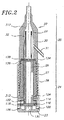
図2を参照すると、デリバリスリーブアセンブリ18の近位端におけるハンドル22は、概ね、エンドキャップ23と、調節可能な部分24と、止血部分25とを含む。調節可能な部分24は、第1のコア部材26と、第1のコア部材26の周りの部分的にねじを切られた部材27と、部分的にねじを切られた部材27の周りの回転ハンドル28とを含む。止血部分25は、第2のコア部材29と、第2のコア部材29の周りのハブ30とを含む。止血チューブ31は、ハブ30から外方向に伸びている。誘導チューブ32は、以下で詳細に記述されるように、ハンドル22の中に配置される。
With reference to FIG. 2, the
図3Aおよび図3Bを参照すると、第1のコア部材26は、概ね、長手方向に伸びている通路33を有するチューブ形状である。環状のフランジ34は、第1のコア部材26の近位端36を形成する。第1のスロット開口38は、第1のコア部材26の外表面から通路33の中への、第1のコア部材26の長軸に沿った連通を可能にする。第2のスロット40は、第1のコア部材26の外表面の長手方向に沿って、遠位端42からフランジ34に向けて走る。フランジ34は、第1のコア部材26の外表面から放射状に伸びている第1のファスナ開口44を含む。スロット40の近位端における長手方向に伸びているアクセス開口46は、スロット40の近位端壁47から第1のファスナ開口44の中へ伸びている。
Referring to FIGS. 3A and 3B, the
図4Aおよび図4Bを参照すると、部分的にねじを切られた部材27は、近位端48および遠位端50を含む。部分的にねじを切られた部材27は、概ね、長手方向に伸びている通路52を有するチューブ形状である。近位端48に向けて、部分的にねじを切られた部材27の外表面は、外側のねじ54を有する。ねじ54は、部分的にねじを切られた部材27の通路52の中へ伸びている、放射状に伸びているドエル開口56を含む。遠位端50に向けて、部分的にねじを切られた部材27は、環状形状の溝58を形成する。部分的にねじを切られた部材27の外表面はまた、環状形状の溝58の遠位付近に配置される、遠位端50に向けたテーパー面60を形成する。尖った環状の先端61は、部分的にねじを切られた部分27の遠位端50を形成する。
With reference to FIGS. 4A and 4B, the partially threaded
図5Aおよび図5Bを参照すると、回転ハンドル28は、好適には、近位端62と遠位端63とを有する細長い円筒を備え、そこから長手方向に伸びている通路64を含む。回転ハンドルの外表面において、回転ハンドル28は、長手方向に沿って伸びている、溝を彫られた部分66を含む。回転ハンドルの内表面において、回転ハンドル28は、遠位端63から内側に伸びているねじを切られた部分68と、ねじを切られた部分68の近位方向に隣接する第1の環状形状のくぼみ70と、第1の環状形状のくぼみ70に隣接し、内表面から内側に伸びている環状のフランジ72と、回転ハンドル28の近位端62に隣接する第2の環状形状のくぼみ74とを含む。ファスナ開口75は、通路64のエリアにおいて回転ハンドル28の外表面から内表面を通過し、回転ハンドル28の近位端62の遠位方向に隣接する第2の環状形状のくぼみ74の近位方向に隣接して配置される。アクセス開口76は、通路64のエリアにおいて回転ハンドル28の外表面から内表面を通過し、第2の環状形状のくぼみ74の遠位方向に隣接し、環状形状のフランジ72の近位方向に隣接している。第2のアクセス開口77はまた、ねじを切られた部分68の近位端において、回転ハンドル28の外表面から内表面を通過する。
Referring to FIGS. 5A and 5B, the rotary handle 28 preferably comprises an elongated cylinder having a
図6Aおよび図6Bを参照すると、第2のコア部材29は、概ね、チューブ形状であり、そこから伸びている通路78を含む。第2のコア部材29の平坦な部分80は、その外表面をさらに規定する。第2のコア部材29の外表面は、長軸に沿って長手方向に進むスロット82を含む。第2のコア部材29はまた、外表面の平坦な部分80から第2のコア部材29の通路78の中に貫通した長手方向に伸びているスロット84を含む。
Referring to FIGS. 6A and 6B, the
図7Aおよび図7Bを参照すると、ハブ30は、テーパーセクション87によって連結されている第1および第2の円筒セクション85、86によって形成される。通路88はハブ30を通って伸びている。通路88は、第1の円筒セクション85から第2の円筒セクション86への移行の間に、テーパーセクション87においてサイズが増加する。止血弁開口90は、第2の円筒セクション86の外表面からその内表面に斜めに伸びている。ハブ30の近位端92において、内表面は通路88の近位端において肩を形成する環状形状の主くぼみ94を含む。追加の半円筒くぼみ96が環状形状の主くぼみ94の円周周りに配置されている。第2の環状形状のくぼみ98は、半円筒くぼみ96が配置されているエリアにおいて、ハブ30の内表面の周りで伸び、ハブ30の近位端92において内表面に沿って内側に放射状に伸びている個々のフランジ100を残している。
With reference to FIGS. 7A and 7B, the
図8に示されている誘導チューブ32はチューブ形状であり、その中に長手方向に伸びている通路を有する。近位セクション110および遠位セクション112は両方とも、直線であり、互いに角度の付けられた関係を形成する。移行セクション113は湾曲され、近位セクション110および遠位セクション112を連結する。
The
ハンドル22の構成要素部品は、好適には、図2に示されたように組み立てられる。第1のスラスト座金114は、第1のコア部材26のフランジ(図3Aを参照)の遠位方向に隣接して、第1のコア部材26の外表面に配置されており、第1のコア部材26は、回転ハンドル28の近位端62(図5Aを参照)を通って回転ハンドル28の中に挿入される。第2のスラスト座金116は、第1のコア部材26の近位端36の近位に配置される。第1のスラスト座金114は、回転ハンドル28の環状のフランジ72と第1のコア部材26のフランジ34との間に挟まれている。フランジ34は、回転ハンドル28の環状形状のフランジ72と第2の環状形状のくぼみ74との間のエリアに座っている。スナップリング118は、第2の環状形状のくぼみ74(図5Bを参照)内に配置され、第2のスラスト座金116に接触し、それにより第1のコア部材26の位置を維持する。
The component parts of the
第1のコア部材ファスナ(図示せず)は、第1のコア部材26の第1のファスナ開口44(図3Bを参照)に係合する。ボールベアリング122は、第1のファスナ開口44内に配置される。回転ハンドル28のアクセス開口76(図5Bを参照)は、第1のコア部材ファスナへのアクセスを可能にする。
A first core member fastener (not shown) engages a first fastener opening 44 (see FIG. 3B) of the
部分的にねじを切られた部材27は、回転ハンドル28の遠位端63から回転ハンドル28の中にねじ込まれる。部分的にねじを切られた部材27の外側のねじ54は、回転ハンドル28の内表面のねじを切られた部材68に係合する。第1のコア部材26は、部分的にねじを切られた部材27の通路52の内側に座っている。部分的にねじを切られた部材27が、図2に示されるように回転ハンドル28内で完全に係合するときに、部分的にねじを切られた部材27の近位端48は、回転ハンドル28の環状形状のフランジ72に接する。
The partially threaded
ドエル124は、部分的にねじを切られた部材27のドエル開口56(図4Bを参照)に係合し、部分的にねじを切られた部材27の外表面から第1のコア部材26の第1のスロット開口38の中に伸びている。部分的にねじを切られた部材27が回転ハンドル28完全に係合するときに、ドエル124は、第1の環状形状のくぼみ70(図5Bを参照)に対応する、回転ハンドル28の通路64のエリアに配置される。部分的にねじを切られた部材27が回転ハンドル28の中にねじ込まれると、ドエル124は、回転ハンドル28の第2のアクセス開口56を通って、部分的にねじを切られた部材27のドエル開口56の中に配置され、ドエル開口56と第2のアクセス開口77と第1のコア部材26の第1のスロット開口38とが並ぶ。
The
エンドキャップ23は、回転ハンドル28の近位端62に固定される。エンドキャップ23は、回転ハンドル28の内表面に接触する円筒形状の第1の接触面126と、回転ハンドル28の近位端62に接触する第2の接触面128とを含む。通路130は、エンドキャップ23を通って伸び、回転ハンドル28の通路64と連通するように配置されている。エンドキャップ23の第1の接触面126は、回転ハンドル28のファスナ開口75と並んでいる。位置決めねじ(図示せず)は、回転ハンドル28にエンドキャップ23を固定するように、ファスナ開口75に係合する。
The
第2のコア部材29は、ハブ30の通路88内に配置される。第2のコア部材29のスロット開口84(図6Bを参照)は、ハブ30の止血弁開口90(図7Bを参照)と並んでいる。スラブ134は、第2のコア部材29の近位方向に隣接して、ハブ30の環状形状の主くぼみ94内に配置される。スラブ134は、好適には、ポリイソプレンで形成され、第2のコア部材29の通路88と連通するように配置される中央の開口136と、第2のコア部材29のスロット82と連通するように配置される誘導チューブ開口138とを含む。スラブ126は、ハブ30の内表面に接着され得る。
The
誘導チューブ32の近位セクション110(図8を参照)は、第1のコア部材26のスロット40の中に挿入される。誘導チューブ32は、スラブ134を通過する。誘導チューブ32の遠位セクション112は、第2のコア部材29のスロット82の中に挿入される。
The
部分的にねじを切られた部材27の尖った環状先端61(図4Bを参照)は、スラブ134の中に押し込まれ、ハブ30の近位端92における個々のフランジ100(図7Aを参照)は、部分的にねじを切られた部材27の環状形状の溝58内で係合し、ハブ30を部分的にねじを切られた部材27に連結する。フランジ100は、部分的にねじを切られた部材27の環状形状の溝58に係合する前に、部分的にねじを切られた部材27のテーパー面60に沿って動く。部分的にねじを切られた部材27とハブ30との組み立ての際、および部分的にねじを切られた部材27が、回転ハンドル28内で完全に係合するときに、ハブ30の近位端92は、回転ハンドル28に接する。さらに、図2に示されるように、誘導チューブ32の中央部分113は、スラブ134を通過する。
The pointed annular tip 61 (see FIG. 4B) of the partially threaded
図9を参照すると、スリーブ19は、好適には、中央管腔139と第1および第2の外側管腔140、141とを有して形成される細長いチューブ状構造である。スリーブは、近位端142と、遠位端143と、外表面144と、内表面145とを含む。スリーブ20は、任意の適切な材料で形成され得るが、好適には、Pebax(登録商標)として市販されているポリエーテルブロックアミドから形成される熱可塑性エラストマで作られる。遠位端143に向けて、スリーブ19は、曲げることが可能な硬度の低いセクションを含む。スリーブ19の硬度の低いセクションは、好適には、55D Pebax(登録商標)で作られ、以下で記述するように、曲げることが可能である。スリーブ19の残りの部分は、好適には、72D Pebax(登録商標)で作られており、該72D Pebax(登録商標)は、55D Pebax(登録商標)よりも硬い。72D Pebax(登録商標)の硬さが、スリーブが過度に曲がることを防止し、それにより潜在的に収縮する身体の血管を通してデリバリシステム10を押す能力をオペレータに与えることにより、以下で記述するように、デリバリシステム10を元々の弁の部位までさらに効果的に前進させることを可能にする。スリーブ19はまた、その長軸に沿ったいずれかの場所で、ワイヤブレードから形成され得る。ワイヤブレードはまた、デリバリシステム10の硬さおよび押し出し能力に寄与し得る。
Referring to FIG. 9, the
図10を参照すると、デリバリスリーブアセンブリの可動セクション20が、断面図で示されている。可動セクションは、概して、フレックスチューブ146と被膜148とを含む。フレックスチューブ146は、好適には、内表面150と、外表面152と、その中で伸びる通路154とを有するチューブ状形状である。フレックスチューブ146は、近位端156と中央セクション158と遠位端160とによってさらに規定される。図11を参照すると、複数のV字型のノッチ162が、例えばレーザーカッティンによって、フレックスチューブ146内で近位端156に隣接して提供される。ノッチ162は尖ったバーブ164を提供するように成型される。フレックスチューブ146の中央セクション158に沿って、円周方向に伸びる細長い開口166が提供される。各細長い開口166は、好適には、湾曲部分170によって連結される2つの細長い部分168を含む。円形部分172は、細長い開口の端において提供される。チューブ部分174は実質的にそのままであり、以下でさらに詳細に記述される。ノッチ176は、フレックスチューブ146の遠位端160において形成される。1つの好適な実施形態において、フレックスチューブ146は、ステンレス鋼ハイポチューブで作られている。
Referring to FIG. 10, the
再び図10を参照すると、被膜148は、好適には、近位端178および遠位端180を有するチューブ状形状であり、外表面182と内表面184とを含み、通路186がその間を長手方向に伸びている。好適な実施形態において、被膜148は、55D Pebax(登録商標)のような硬度の低い材料で形成される。被膜148の硬度の低い55D Pebax(登録商標)は、以下で記述するように伸びて、曲がることが可能である。
Referring again to FIG. 10, the
可動セクション20は、フレックスチューブ146を被膜148の内側に配置することによって組み立てられる。以下に概略が述べられるように、被膜148は、組み立ての前に引き伸ばされて、可動セクション20に望ましい特徴を与える。フレックスチューブ146の外表面は、被膜148の内表面と接触する。被膜148の近位端178は、フレックスチューブ146の近位端156から近位方向に伸び、被膜148の遠位端180は、フレックスチューブ146の遠位端160から遠位方向に伸びる。
The
図12を参照して、可動セクション20の代替の実施形態は、近位端190および遠位端192を有するコネクタ188を含む。コネクタ188は、チューブ状であり、その中を通って長手方向に伸びる通路194を有する。環状形状フランジ196は、コネクタ188の内表面198から突出する。
With reference to FIG. 12, an alternative embodiment of the
コネクタ188を含む可動セクション20の代替の実施形態を組み立てるためには、フレックスチューブ146の近位端156が環状形状フランジ196に接するまで、コネクタ188の通路194の中に挿入される。フレックスチューブ146の外表面152は、コネクタ188の内表面198に接触し、接着剤を使用してそこに接着され得る。被膜148は、フレックスチューブ146およびコネクタ188の上に配置される。コネクタ188の近位端190は、被膜148の近位端178から近位方向に伸び、被膜148の遠位端180は、フレックスチューブ146の遠位端160から遠位方向に伸びる(図10を参照)。
To assemble an alternative embodiment of the
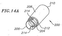
図13を参照して、シュラウドセクション21が断面で示されている。シュラウドセクション21は一般的に、シュラウド200およびリング202を含む。図14Aおよび図14Bを参照して、シュラウド200は好ましくは円筒形状であり、3つの連続的な円筒状のセクション:近位端206の近くの縁204、遠位端210の近くの本体208、およびその間に位置するネック212を含む。通路213は、シュラウド200を通って伸び、シュラウド200は内表面216および外表面218を含む。スロット214は、シュラウド200の近位端210からネック212の中に走り込む。ネック212は、縁204および本体208よりも小さな円周を有し、その結果シュラウド200の外表面218に沿って溝220を生じる。
Referring to FIG. 13, the
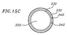
ここで図15A〜図15Cを参照して、リング202は、近位端222、遠位端224およびその中を通って長手方向に伸びる通路225を有する。リング202は、近位外表面226、遠位外表面228、および内表面230を含む。外面232は、リング202の近位外表面および遠位外表面226,228に対して垂直に走り、一般的に互いに並行に走る近位外表面および遠位外表面226,228を接続する。内表面230は、遠位端224に向かう角度のついた表面234を含み、リング202の遠位端224の近くの、リングの通路225の直径を増大させる。
Referring now to FIGS. 15A-15C, the
スロット236は、リング202の遠位端の中に伸び、内表面230の方に、リング202の中心軸に並行に遠位外表面228を通り、外面232に相対するスロット面238を作成する。第1の管腔240および第2の管腔242は、スロット面238からリング202の外面232へ伸びる。近位外表面226は、近位端222からリング202の外面232に向かってリング202の中心軸と並行に走る第1の半円筒形くぼみ244、および第2の半円筒形くぼみ246も含む。第1の半円筒形くぼみ244は、第1の管腔240と整列させられ、第2の半円筒形くぼみ246は第2の管腔242と整列させられる。
The
図13に従って、シュラウドセクション21は、シュラウド200の近位端をリング202の中に挿入することによって形成される。縁204は、曲がってこれを可能にする。リング202は、溝220(図14Bを参照)にぴったりと嵌入することにより、リング202(図15Aを参照)の内表面230ならびに近位端および遠位端222、224は、シュラウド200の外表面218と接触する。リング202は、シュラウド200(図14Aを参照)のスロット214のうちのいずれかが、リング202のスロット236と整列するように位置する。
According to FIG. 13, the
図16を参照して、バルーンカテーテル15は、チューブセクション16およびサポート17を含んでいる。チューブセクション16は、それらの両方ともが、サポート17に接続されている誘導ワイヤシャフト248、バルーンシャフト250、およびバルーン252を含む。近位端256および遠位端258を有する誘導ワイヤシャフト248は、内表面260、外表面262、およびその中を通って長手方向に伸びる通路264を含む。誘導ワイヤシャフト248は硬さおよび柔らかさの必要に従って、ナイロン、組まれたステンレススチールワイヤ、またはその長さに沿った異なる部分でのPebax(登録商標)で形成され得る。Teflon(登録商標)は、誘導ワイヤシャフト248の内表面260を形成するために使用され得る。近位端266および遠位端268を有するバルーンシャフト250は、内表面270、外表面272、およびその中を通って長手方向に伸びる通路274を含む。バルーンシャフト250は硬さおよび柔らかさの必要に従って、ナイロン、Pebax(登録商標)、またはその長さに沿った異なる部分での組まれたステンレススチールの任意の組み合わせで形成され得る。
Referring to FIG. 16, the
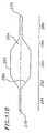
ここで図17A〜図17Bを参照して、バルーン252は、近位端276および遠位端278を有し、内表面280、外表面282、およびその中を通って長手方向に伸びる通路284を含む。近位端276から遠位端278に向かって観察した場合、バルーン252は5つの部分:第1の細い部分286、第1の円錐部分288、主円筒形部分290、第2の円錐部分292、および第2の細い部分294、を含む。バルーン252はナイロンで形成され得、6〜8atmの破裂圧と見積られる。好ましい実施形態において、バルーンの拡大された直径は、約20〜28mmの範囲におよび、さらに好ましくは、約23mmである。
Referring now to FIGS. 17A-17B, the
再度図16を参照して、サポート17は、ワイヤ入り口開口296、流体入り口開口298、および主シャフト開口300を含む。ワイヤ入り口開口296は、内部表面302を含み、主シャフト開口300は同様に、内部表面304を含む。開口296、298、300は、互いに連通するように配置されている。
Referring again to FIG. 16, the
バルーンカテーテル15は、図16に示されるように組み立てられる。誘導ワイヤシャフト248は、主シャフト開口300の中に挿入される。誘導ワイヤシャフト248の近位端は、ワイヤ入り口開口296に配置され、誘導ワイヤシャフト248の外表面262は、ワイヤ入り口開口296の内部表面302に、例えば接着剤で固定される。誘導ワイヤシャフト248は、主シャフト開口300よりも直径が小さく、従って主シャフト開口300の内部表面304に接触しない。
The
バルーンシャフト250は、誘導ワイヤシャフト248の上に配置される。バルーンシャフト250の近位端266は、サポート17の主シャフト開口300に配置され、バルーンシャフト250の外表面272は、主シャフト開口300の内部表面304に固定される。図16に示されるように、誘導ワイヤシャフト248は、バルーンシャフト250よりも直径が小さく、誘導ワイヤシャフト248の外表面262は、バルーンシャフト250の内表面270と接触せず、空気の流れを可能にする。
誘導ワイヤシャフト248の近位端256は、バルーンシャフト250の近位端266から近位方向に伸び、誘導ワイヤシャフトの遠位端258は、バルーンシャフト250の遠位端268から遠位方向に伸びる。
The proximal end 256 of the
バルーン252の近位端276は、バルーンシャフト250の遠位端268の上に配置される。第1の細い部分286のエリアにおける、バルーン252の内表面280は、バルーンシャフト250の外表面272に固定される。バルーン252の遠位端278は、誘導ワイヤシャフト248の遠位端258の上に配置される。第2の細い部分294のエリアにおけるバルーン252の内表面280は、誘導ワイヤシャフト248の外表面262に固定される。バルーン252は、紫外光線またはレーザ溶接での接着剤の硬化を伴うプロセスによって、バルーンシャフト250および誘導ワイヤシャフト248に固定され得る。
The
第1および第2のマーカバンド306、308が、バルーン252の通路284内の誘導ワイヤシャフト248に沿って配置される。マーカバンド306、308は、接着剤またはスエージ加工によって、誘導ワイヤシャフト248の外表面262に固定され得る。第1のマーカバンド306の位置は、バルーン252(図17Bを参照)の第1の円錐部分288と主円筒形部分290との間の移行におおよそ対応する。第2のマーカバンド308の位置は、バルーン252の主円筒形部分290と第2の円錐部分292との間の移行におおよそ対応する(図17Bを参照)。マーカバンド306、308は、90パーセントプラチナおよび10パーセントイリジウムで形成されることにより、患者内のバルーンカテーテル19の位置を、当技術分野で公知のプロセス、x線透視によって示し得る。バルーン252から遠位方向に位置するソフトチップ310は誘導ワイヤシャフト248の遠位端258の上に配置される。
First and
デリバリスリーブアセンブリ18は、スリーブ19と可動セクション20とを接合することによって形成される。図10に示されるように、スリーブ19の遠位端143は、被膜148の通路186およびフレックスチューブ146の通路154の中に挿入される。スリーブ19は、第1および第2外管腔140、141がフレックスチューブ146の細長い開口166の湾曲部分170と整列するように、可動セクション16に対して配置される。スリーブ19の外表面144は、フレックスチューブ146の内表面150に、例えば熱接合または接着剤接合によって固定される。さらにバーブ164は、スリーブ19の遠位端143と係合し、接続を作る。被膜148の内表面184も、接着剤または熱接合によって被膜148の近位端178で、スリーブ19の外表面144に固定される。
コネクタ188を含む代替の実施形態(図12を参照)において、スリーブ19の外表面144は、コネクタ188の近位端190に向かって、コネクタ188の内表面198に、その遠位端143において固定されている。スリーブ19の遠位端143は、コネクタ188の環状形状フランジ196に接する。
In an alternative embodiment that includes a connector 188 (see FIG. 12), the
シュラウドセクション21も、可動セクション20に接合されて、デリバリスリーブアセンブリ18(図10を参照)を形成する。シュラウド200の近位端206は、被膜148の遠位端180において、被膜148の通路186の中に挿入される。シュラウド200の近位端206は、フレックスチューブ146の遠位端160において、フレックスチューブ146の通路154に中にさらに挿入される。シュラウド200のスロット214は、フレックスチューブ146のノッチ176と整列させられる(図11および図14A)。
The
縁204のエリアにおけるシュラウド200の外表面218は、フレックスチューブ146の内表面150に固定される。リング202の近位外表面226は、フレックスチューブ146の遠位端160に隣接したフレックスチューブ146の内表面150に固定される。フレックスチューブ146の遠位端160は、リング202の外面232に接する。シュラウドセクション21は、メカニカルボンドおよび接着剤で、フレックスチューブ146に固定され得る。
The
被膜148の内表面184は、リング202の遠位外表面228に固定される。被膜148の内表面184も、本体208のエリアにおいて、シュラウド200の外表面218に固定される。これらの接続は、接着剤もしくは熱結合、または両方によってなされ得る。シュラウド200の本体208は、被膜148の遠位端180から遠位方向に伸びる。
The
スリーブ19の近位端142が、ハブ30の通路88の中に挿入され、スリーブ19の外表面144が、ハブ30の内表面に、例えば接着剤で固定されるとき、デリバリスリーブアセンブリ18は、ハンドル22に接続される。
When the
図2に示されているプルワイヤ312は、デリバリシステム10の中に挿入されている。プルワイヤ312の第1の端末が、第1のコア部材26の第1のファスナ開口44に配置される。第1のコア部材ファスナ(図示されず)は、ボールベアリング122を圧し、ボールベアリング122は、プルワイヤ312を第1のファスナ開口44において固定する。プルワイヤ312は、第1のコア部材26の、長手方向に伸びるアクセス開口46(図3Bを参照)を通る。プルワイヤ312は、第1のコア部材26のスロット40に位置する誘導チューブ32の通路、スラブ134の誘導チューブ開口138、第2のコア部材29のスロット82を通り、次にハブ30の通路88を通る。プルワイヤ312は次に、スリーブ19(図9を参照)の第1の管腔140を通る。プルワイヤ312は、スリーブ19を出てフレックスチューブ146の通路154を通る(図10を参照)。プルワイヤ312は、リング202の第1の半円筒形くぼみ244および第1の管腔240を通る。プルワイヤ312は、リング202のスロット面238に対して引張られる。プルワイヤ312は次に、リング202の第2の管腔242および第2の半円筒形くぼみ246を通って戻される。プルワイヤ312は再び、フレックスチューブ146の通路154を通る。プルワイヤ312は、デリバリスリーブ19の第2の外管腔141を、(再び)ハブ30の通路88を、(再び)誘導チューブ32の通路を、第1のコア部材26のスロット40のアクセス開口46を通る。プルワイヤ312の第2の端末は、ボールベアリング122上の第1のコア部材ファスナ(図示されず)によって発揮される圧力によって第1のコア部材26に固定され、これによってプルワイヤ312は固定される。プルワイヤ312は、ニチノールまたはステンレススチールから形成され得る。
The
ここで、図1および図16を参照して、心臓弁デリバリシステム10を使用する好ましい方法がさらに詳細に記述される。本明細書に開示されたデバイスおよび方法は、特に狭窄大動脈弁を取り替えるために良く適している。動脈弁内に補綴弁を配置する前に、狭窄した動脈弁の葉状部を予め拡張することが必要であり得ることを当業者は理解する。事前拡張により、動脈を通る流れエリアが大きくなり、葉状部に十分な大きさの開口を作成して補綴弁を受け取る。事前拡張は好ましくは、膨張可能な部材、例えば膨張バルーンカテーテルを使用して達成される。事前拡張および弁取替えに関するさらなる詳細は、2002年5月2日に出願された出願人の同時係属出願第10/139,741号に見出され得る。
A preferred method of using the heart
心臓弁デリバリシステム10の組み立ておよび動作がここで記述される。組み立ての間、バルーンカテーテル15は、ハンドル22の組み立てによって作成された開口およびデリバリスリーブアセンブリ18の中に挿入される。バルーンカテーテル15のサポート17は、ハンドル22に対して近位方向に位置している。バルーンシャフト250、および誘導ワイヤシャフト248は、エンドキャップ23(図2を参照)の通路130、第1のコア部材26の通路33、スラブ134の中央開口136、第2のコア部材29の通路78、ハブ30の通路88、スリーブ19の中央管腔139、およびフレックスチューブ146の通路154を通る。バルーンシャフト250は、図18Aに従ってシュラウド200の通路213の中を通る一方、誘導ワイヤシャフト248は、シュラウド200の通路213を通る。バルーン252の近位端276は、シュラウド200の通路213に位置し、バルーン252は、シュラウド200の遠位端210から遠位方向に伸びる。
The assembly and operation of the heart
図18Aに示されるように、補綴弁11は、シュラウド200の遠位端210から遠位方向に、バルーン252の主円筒形部分290に取り付けられている。弁11は当技術分野で公知であり、図1に示されるように、バルーン252上で第1の位置にしぼむことが可能である。あるいは、弁11は、図18Bに示されるように、バルーン252に取り付けられ得、かつシュラウド200の内側に配置され得る。
As shown in FIG. 18A, the
弁11は、様々に異なる形式を取り得る。好ましい実施形態において、弁は、弁構造を支える膨張可能なステント部分を一般的に含む。ステント部分は半径方向の十分な力を有して治療部位において弁を保持し、かつ狭窄弁葉状部のはね返りに抵抗する。好ましいバルーン膨張可能弁の実施形態に関するさらなる詳細は、IMPLANTABLE PROSTHETIC VALVEと各々題された出願人の米国特許第6,730,118号および第6,893,460号に見出され得、これらは本明細書に参照により援用される。デリバリシステムは、自己膨張可能な補綴弁と共に使用し得ることも理解し得る。例えば、自己膨張可能な弁を使用するとき、プッシャが、バルーンカテーテルの代わりに使用されることにより、デリバリスリーブアセンブリから自己膨張する弁を押出し得る。
The
例示される実施形態を引き続き参照して、誘導ワイヤ14は、誘導ワイヤシャフト248の通路264に配置されることにより、誘導ワイヤシャフト248の遠位端258から遠位方向に、かつバルーンカテーテル15のサポート17のワイヤ入口開口296から近位方向に伸びる。たどるためにカテーテルを人体に挿入するプロセスは、例えばENDOVASCULAR DELIVERY SYSTEMと題され、本明細書に参照により援用されている米国特許第5,968,068号によって、当技術分野において公知である。
With continued reference to the illustrated embodiment, the
誘導ワイヤ14は、身体の血管の内径を膨張させることにより、図19に示された導入シースアセンブリ400を導入する拡張器(図示されず)を介して、誘導ワイヤ14の上で身体内に配置される。好ましい拡張器の直径は、12と22Frenchの間を範囲とする。導入シースアセンブリ400は、導入スリーブ402および導入スリーブ402の近位端に取り付けられた導入筐体404を含む。導入シースアセンブリの直径は、22または24Frenchが好ましい。
The
一連の弁は、導入筐体404の内側に位置する。導入筐体404の近位端にエンドピース406が取り付けられ、エンドピースは、一連の弁のエリアの中で導入筐体404の中に伸びる開口、および導入筐体404の遠位端に面するリッジ408を有する。導入スリーブ402は、身体の血管の中に伸び、導入筐体404は、導入スリーブ402の近位端での近位端で、身体の血管の外側に位置している。好ましい実施形態において、導入スリーブ402は、親水性の被膜が施され、約9インチ身体の血管の中に伸び、腸骨の分岐を過ぎて患者の腹大動脈の中に入る。導入シースアセンブリ400は、安全かつ効果的な態様で補綴弁を動脈の中に進めるメカニズムを提供する。
A series of valves are located inside the
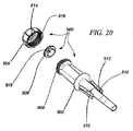
図20を参照して、ローダアセンブリ500は、ローダ502、ローダキャップ504、およびローダシール506を含む。ローダ502は、チューブ状であり、ローダキャップ504との接続のための外部ねじ508を、近位端に有している。ローダ502は、それと並行に伸び、かつローダ502の近位端に面するスナップリッジ512を有しているフレキシブルフランジ510を含む。ローダキャップ504は、その近位端においてローダキャップ開口514、およびローダ502の外部ねじ508と係合するためにねじを切られた内表面516を含む。ローダシール506は、ローダキャップ504に固定され、ローダシール開口518は、ローダキャップ開口514と整列させられる。
Referring to FIG. 20,
図21Aを参照して、スリーブ19がローダキャップ開口514およびローダシール開口518と係合するとき、ローダキャップ504およびローダシール506は、デリバリシステム10に通される。図21Bに示されるように、誘導ワイヤ14の上を通るデリバリシステム10の遠位端は、ローダ502の近位端の中に挿入される。ローダキャップ504は、ローダ502の近位端にねじ込まれる。
Referring to FIG. 21A,
図22を参照して、ローダ502のフレキシブルフランジ510は、導入筐体404のエンドピース406にぱちんとはまる。この位置において、エンドピース406のリッジ408は、フレキシブルフランジ510のスナップリッジ512に対して耐え、ローダ502は、導入筐体404の内側に位置する一連の弁を通り、従ってデリバリシステム10を導入シースの内通路と連通する状態に、従って身体の血管と連通する状態にする。ローダアセンブリ500は有利にも、患者からの有意な血液の損失なく、デリバリシステム10が導入シースアセンブリ400の中に導入されることを可能にする。
Referring to FIG. 22, the
補綴弁11、バルーンカテーテル15、およびデリバリスリーブアセンブリ18は、好ましくは単一のユニットとして、導入シースを通って誘導ワイヤ14の上を進められる一方、元々の弁の部位へ身体の血管をたどる(図1を参照)。1つの有利な特徴は、デリバリシステム10が優れた押し出し能力を提供することにより、導入シースを通る補綴弁11の前進を容易にすることである。一実施形態において、デリバリシステム10は、十分な押し出し能力を提供して、弁11またはシュラウド200の外周よりも2French小さい内周を有する導入シースを通る。
The
図1に示されるように、補綴弁11が大動脈弓13に達するとき、以下に記述されるデリバリシステム10の可動機能が起動されることにより、大動脈弓付近での補綴弁11の前進を容易にする。さらに詳細には、可動セクション20の曲がりは、弁11および/またはシュラウド200(図14A参照)の遠位端210を大動脈弓13の内表面から遠ざけることを補佐する。結果として、大動脈弓13付近での弁11のレトログレードの前進は、大動脈13または弁11を損傷することなく達成され得る。1つの好ましいデリバリ方法は、弁が、弁と大動脈との接触がほとんどなく、または全くなく大動脈弓を進むことである。
As shown in FIG. 1, when the
例示される実施形態において、オペレータが、回転ハンドル28を回転させたとき、デリバリシステム10の可動機能が達成される(図2を参照)。回転ハンドル28が回転されたとき、ねじを切られた部分68は、回転しない部分的にねじを切られた部材27(図4Aを参照)の外部ねじ54と関連して作用する。従って、回転ハンドル28は、部分的にねじを切られた部材27に対して一定の割合で動く。第1のコア部材26も、部分的にねじを切られた部材27に対して一定の割合で動く(図2を参照)。ドエル124は、第1のコア部材26と部分的にねじを切られた部材27との間での相対的な回転を妨げる。
In the illustrated embodiment, the movable function of the
第1のコア部材26が、部分的にねじを切られた部材27から遠位側に動くとき、ボールベアリング122によって第1のコア部材26に接続されたプルワイヤ312は、リング202のスロット面238に対して力を及ぼす(図15Aを参照)。プルワイヤ312は、リング202をハンドル22の方に引く。プルワイヤ312が沿って通るデリバリシステム10の側面は、フレックスチューブ146の細長い開口166が集結するように、可動セクション20に沿って曲がる(図11を参照)。可動セクション20は、プルワイヤ312における圧力が、解除されるまで曲がっている。従って、回転ハンドル28の追加的な回転は、追加的な曲げを生じる。回転ハンドル28のねじを切られた部分68と部分的にねじを切られた部材27の外部ねじ54との摩擦は、プルワイヤ312を緊張した状態に保持するのに十分であり(図4Aおよび図4Bを参照)、従って、オペレータが回転ハンドル28を放したときも、可動セクション20における曲がりの形状を保つ。
When the
被膜148(図10を参照)の元来の硬さ、およびバルーンカテーテル15(図16を参照)の自然な硬さは、可動セクション20の曲がりに対抗して作用する。プルワイヤ312に対する力が、可動セクション20を曲げる一方、上記の被膜148およびバルーンカテーテル15の硬さは、曲げに抵抗し、従って回転ハンドル28の回転に従って、まっすぐから十分に湾曲した範囲にわたってデリバリシステム10をしかるべき位置に「ロック」する。被膜148はまた、フレックスチューブ146(図10を参照)から身体の血管を保護し、フレックスチューブ146は、被膜148がない場合、身体の血管の表面をこすり、または身体の血管を引き裂く。
The original hardness of the coating 148 (see FIG. 10) and the natural hardness of the balloon catheter 15 (see FIG. 16) act against the bending of the
バルーンカテーテル15が、元々の弁の部位に前進させられるとき、オペレータは、マーカバンド306、308(図16を参照)を使用し、当技術分野で周知のx線透視のプロセスに従って、弁20の位置を識別する。オペレータは、ハブ30を静止の状態に保持しながら、回転ハンドル28を作動させることによって、弁11の位置を調節し得る(図2を参照)。弁の位置に対するさらなる制御は、ハブ30を捻ることによって達成され得る。スリーブ19は、ハブ30に取り付けられ、デリバリシステム10は、十分に硬く、捻りの動きを遠位端に伝える。フレックスチューブ146のチューブ部分174が、互いに接触しているとき、捻りの動きは、可動セクション20を介して移転される(図11を参照)。そのような接触は、フレックスチューブが十分に曲がったとき起こり得るか、またはチューブ部分174が互いに接触するように細長い開口の湾曲した部分170を閉じるように捻っている間に起こり得る。
When the
フレックスチューブ148のすべての残りチューブ部分174(図11を参照)が、互いに接触し、可動セクション20が十分に湾曲しているとき、デリバリスリーブアセンブリ18(図1を参照)は最も硬い。この位置において、可動セクション20の形状は、たどる容易さのために(図1に示されるように)大動脈弓13の形状と密接に対応することが好ましい。狭窄葉状部12を横切って押し進むとき、可動セクション20は、患者の上行大動脈に位置し、スリーブ19の硬度が低いセクションは大動脈弓13に対して曲がり、(図1を参照)、それによって大動脈の内壁への損傷を防ぐ。
The delivery sleeve assembly 18 (see FIG. 1) is stiff when all remaining
デリバリシステム10が前進することにより、弁11が元々の弁に隣接して位置したあと、バルーンカテーテル15は、デリバリスリーブアセンブリ18に対して遠位方向に進められ、元々の葉状部内で弁11をさらに良い位置に位置づける。これを達成するために、バルーンカテーテル15は、スリーブ19および可動セクション20を通ってスライド可能に進められる。別の有利な特徴においては、デリバリスリーブアセンブリ18は、医師が可動セクション20の湾曲を調節することにより、補綴弁11を元々の弁に対して正しく整列させることを有利にも可能にする。結果として、バルーンカテーテル15が遠位方向に進められたとき、補綴弁は、元々の弁の中央の中に進む。さらに、デリバリシステム10は、十分な押し出し能力を提供し、狭窄葉状部12を横切ってバルーンカテーテル15および弁11を押すか、または代替的に、狭窄葉状部12を横切ってバルーンカテーテル15を押す。シュラウド200(図14Aを参照)も、このプロセス中に狭窄葉状部12を横断し得る。
Advancement of the
狭窄葉状部12が押しのけられると、デリバリシステム10は図23に示されるように、元々の弁の部位に弁11を配置する。スリーブ19の硬度が低いセクションは、大動脈弓13に対して曲がる一方、可動セクション20は、上行大動脈を通り、調節されて弁11を位置づける。弁11は、膨張可能なバルーンであり、いったん位置づけられると、バルーン252は膨らまされて、元々の弁の部位に弁11の位置を固定する。バルーン252は次に空気が抜かれ、デリバリシステム10が誘導ワイヤ14上を戻り、導入シースを通って身体脈管構造を出るとき、デリバリシステム10全体は、引き出される。誘導ワイヤ14が次に引き出され、その後導入シースが引き出される。
When the
本発明の代替の実施形態において、弁11はシュラウド200の内側に配置され、デリバリスリーブアセンブリ18(図1を参照)は、弁11がいったん元々の弁の部位に到達すると、引っ込められる。オペレータがサポート17を一定に保持し、ハンドル22を(近位方向に)引き戻すとき、デリバリスリーブアセンブリ18は引っ込められ、これによって、デリバリスリーブアセンブリ18は、近位方向に引っ込められ、弁11を元々の弁の部位に露出させ、かつバルーン252が、図23に示されるように膨らむことを可能にし、このようにして上記のように弁11を配置する。
In an alternative embodiment of the invention, the
心臓弁デリバリシステム10は、補綴心臓弁を患者の脈管構造を通って進める改善されたデバイスおよび方法を提供することは、理解される。1つの好ましい実施形態において、本明細書に記述されたコンポーネントの協働は、覆われていない補綴弁が、安全な態様で患者の脈管構造を通って大動脈弓付近を進められることを可能にする。従って、本デリバリシステムは、外側のシースが大動脈弓の中に導入されることを必要とせずに、補綴弁が大動脈弓付近を前進することを可能にする。これは有利な特徴である。なぜならば、シースの使用により、デリバリシステムの直径が増大し、それによって、弁のデリバリが複雑になるからである。大動脈の内壁を損傷することなく大動脈弓をナビゲートする改善された可動メカニズムを提供することに加えて、本デリバリシステムは、優れた押し出し能力を提供することにより、医者は元々の弁の中に前進する間、補綴弁の動きおよび位置に対して優れた制御を有することは、当業者によって理解される。この特徴は、狭窄葉状部を横切るときに特に有利である。従って、本発明の実施形態は、大動脈における外側のシースの必要性をなくす一方、狭い脈管構造および/または狭窄弁葉状部を通るために十分な押し出し能力を提供する可動なアセンブリを使用して、元々の大動脈弁の部位まで補綴弁を前進させる改善されたデリバリシステムを提供する。結果として、本発明の実施形態は、レトログレードのアプローチを使用して、狭窄大動脈弁の部位にバルーン膨張可能な補綴弁を経皮的に前進させる改善されたデバイスおよび方法を提供する。
It is understood that the heart
本発明はその好ましい実施形態において記述されたが、使用された言葉は説明のためであり、制限のためではないことが理解されるべきである。従って、本発明の真の範囲および精神から逸脱することなく、添付された請求項の範囲内で変更がなされ得る。 While this invention has been described in its preferred embodiments, it is to be understood that the language used is for purposes of illustration and not limitation. Accordingly, changes may be made within the scope of the appended claims without departing from the true scope and spirit of the invention.
Claims (20)
該スリーブの遠位端に連結されている選択的に可動なセクションと、
該スリーブと該可動セクションとを通って伸びている細長いバルーンカテーテルと、
該細長いバルーンカテーテルの遠位端部分に沿って膨張性バルーンを覆うように配置される補綴弁と
を備えているデリバリシステムであって、
該スリーブと、該可動セクションと、該バルーンカテーテルと、該補綴弁とは、単一のユニットとして患者の脈管構造を通る前進のために構成されており、該補綴弁は、該可動セクションの遠位端部分に隣接している、デリバリシステム。 A tubular sleeve;
A selectively movable section coupled to the distal end of the sleeve;
An elongated balloon catheter extending through the sleeve and the movable section;
A prosthetic valve disposed over the inflatable balloon along the distal end portion of the elongated balloon catheter;
The sleeve, the movable section, the balloon catheter, and the prosthetic valve are configured for advancement through the patient's vasculature as a single unit, the prosthetic valve being configured for the movable section. A delivery system adjacent to the distal end portion.
該デリバリスリーブアセンブリの可動セクションを形成するスロットを付けられたチューブであって、該可動セクションは、該可動セクションが実質的に直線である第1の構成と、該可動セクションが曲げられている第2の構成とを有し、該可動セクションは被膜によって包まれており、該被膜は伸縮可能であることにより、該被膜は、該第2の構成から該第1の構成に向けて該可動セクションを偏らせる、スロットを付けられたチューブと、
該デリバリスリーブアセンブリの該主管腔を通って伸びている細長いバルーンカテーテルであって、補綴弁は、該バルーンカテーテルの遠位端に位置しているバルーンに取付けられている、細長いバルーンカテーテルと
を備えているデリバリシステム。 A delivery sleeve assembly having a main lumen;
A slotted tube forming a movable section of the delivery sleeve assembly, the movable section comprising a first configuration in which the movable section is substantially straight and a first configuration in which the movable section is bent. The movable section is encased by a coating, and the coating is stretchable so that the coating is moved from the second configuration toward the first configuration. Biased, slotted tube, and
An elongate balloon catheter extending through the main lumen of the delivery sleeve assembly, wherein the prosthetic valve is attached to a balloon located at the distal end of the balloon catheter; Delivery system.
バルーンカテーテルのバルーンを覆うように補綴弁を取付けることと、
可動セクションを有するデリバリスリーブアセンブリの内側に該バルーンカテーテルを配置することであって、該可動セクションは、該デリバリスリーブアセンブリの長手方向に沿って走り、ハンドルの運動部材に装着されているプルワイヤによって作動される、ことと、
該患者の腸骨動脈および大腿動脈を通って、大動脈弓を越えて該元々の弁の部位へ弁を押すことによって、該元々の弁への該補綴弁を追跡することであって、該追跡することによって、該ハンドルが第1の方向に回転させられる場合には、該運動部材はプルワイヤを引き、該可動セクションを曲げ、かつ、該追跡することによって、該ハンドルが第2の方向に回転させられる場合には、該運動部材はプルワイヤを解放し、該デリバリスリーブアセンブリの堅さが該可動セクションをまっすぐに伸ばすことを可能にする、ことと、
該バルーンを膨張させることにより、該元々の弁の部位に該補綴弁を配置することと
を包含する、方法。 A method of delivering a prosthetic valve to a patient's original valve site, the method comprising:
Attaching a prosthetic valve to cover the balloon of the balloon catheter;
Placing the balloon catheter inside a delivery sleeve assembly having a movable section, the movable section running along the length of the delivery sleeve assembly and actuated by a pull wire attached to a moving member of the handle And that
Tracking the prosthetic valve to the original valve by pushing the valve through the iliac and femoral arteries of the patient and over the aortic arch to the site of the original valve, the tracking Thus, when the handle is rotated in the first direction, the motion member pulls the pull wire, bends the movable section, and the tracking causes the handle to rotate in the second direction. If so, the motion member releases the pull wire, allowing the stiffness of the delivery sleeve assembly to extend the movable section straight;
Placing the prosthetic valve at the site of the original valve by inflating the balloon.
バルーンカテーテルの遠位端部分に沿ってバルーンを覆う膨張性補綴弁を配置することと、
プルワイヤによって作動される可動セクションを有するデリバリスリーブアセンブリの内側に該バルーンカテーテルを配置することと、
該可動セクションの湾曲を選択的に調節し、前進を容易にしながら、該補綴弁と該デリバリスリーブアセンブリとを該元々の弁の部位に向けて、実質的に単一のユニットとして前進させることと、
該補綴弁を該デリバリスリーブアセンブリの外に出し、該元々の弁の部位に前進させることと、
該バルーンを膨張させ、該元々の弁の部位に該補綴弁を配置することと
を包含する、方法。 A method of delivering a prosthetic valve to a patient's original valve site, the method comprising:
Placing an inflatable prosthetic valve over the balloon along the distal end portion of the balloon catheter;
Placing the balloon catheter inside a delivery sleeve assembly having a movable section actuated by a pull wire;
Advancing the prosthetic valve and the delivery sleeve assembly substantially as a single unit toward the original valve site while selectively adjusting the curvature of the movable section to facilitate advancement; ,
Taking the prosthetic valve out of the delivery sleeve assembly and advancing it to the original valve site;
Inflating the balloon and placing the prosthetic valve at the site of the original valve.
Applications Claiming Priority (2)
| Application Number | Priority Date | Filing Date | Title |
|---|---|---|---|
| US11/152,288 US7780723B2 (en) | 2005-06-13 | 2005-06-13 | Heart valve delivery system |
| PCT/US2006/022540 WO2006138173A2 (en) | 2005-06-13 | 2006-06-09 | Heart valve delivery system |
Publications (1)
| Publication Number | Publication Date |
|---|---|
| JP2008546431A true JP2008546431A (en) | 2008-12-25 |
Family
ID=37022845
Family Applications (1)
| Application Number | Title | Priority Date | Filing Date |
|---|---|---|---|
| JP2008515981A Withdrawn JP2008546431A (en) | 2005-06-13 | 2006-06-09 | Heart valve delivery system |
Country Status (12)
| Country | Link |
|---|---|
| US (12) | US7780723B2 (en) |
| EP (2) | EP2319459B1 (en) |
| JP (1) | JP2008546431A (en) |
| CN (2) | CN102247224B (en) |
| AT (1) | ATE505154T1 (en) |
| CA (2) | CA2609201C (en) |
| DE (1) | DE602006021309D1 (en) |
| DK (2) | DK1903989T3 (en) |
| ES (2) | ES2432648T3 (en) |
| HK (2) | HK1110765A1 (en) |
| PL (1) | PL1903989T3 (en) |
| WO (1) | WO2006138173A2 (en) |
Cited By (1)
| Publication number | Priority date | Publication date | Assignee | Title |
|---|---|---|---|---|
| JP2019532767A (en) * | 2016-11-07 | 2019-11-14 | エドワーズ ライフサイエンシーズ コーポレイションEdwards Lifesciences Corporation | Device for the introduction and operation of multiple telescopic catheters |
Families Citing this family (495)
| Publication number | Priority date | Publication date | Assignee | Title |
|---|---|---|---|---|
| US6006134A (en) * | 1998-04-30 | 1999-12-21 | Medtronic, Inc. | Method and device for electronically controlling the beating of a heart using venous electrical stimulation of nerve fibers |
| EP0850607A1 (en) | 1996-12-31 | 1998-07-01 | Cordis Corporation | Valve prosthesis for implantation in body channels |
| US6254564B1 (en) | 1998-09-10 | 2001-07-03 | Percardia, Inc. | Left ventricular conduit with blood vessel graft |
| US8579966B2 (en) | 1999-11-17 | 2013-11-12 | Medtronic Corevalve Llc | Prosthetic valve for transluminal delivery |
| US7018406B2 (en) * | 1999-11-17 | 2006-03-28 | Corevalve Sa | Prosthetic valve for transluminal delivery |
| US20070043435A1 (en) * | 1999-11-17 | 2007-02-22 | Jacques Seguin | Non-cylindrical prosthetic valve system for transluminal delivery |
| US8016877B2 (en) * | 1999-11-17 | 2011-09-13 | Medtronic Corevalve Llc | Prosthetic valve for transluminal delivery |
| US8241274B2 (en) | 2000-01-19 | 2012-08-14 | Medtronic, Inc. | Method for guiding a medical device |
| US7749245B2 (en) | 2000-01-27 | 2010-07-06 | Medtronic, Inc. | Cardiac valve procedure methods and devices |
| DE10010073B4 (en) * | 2000-02-28 | 2005-12-22 | Fraunhofer-Gesellschaft zur Förderung der angewandten Forschung e.V. | Anchoring for implantable heart valve prostheses |
| DE10010074B4 (en) | 2000-02-28 | 2005-04-14 | Fraunhofer-Gesellschaft zur Förderung der angewandten Forschung e.V. | Device for fastening and anchoring heart valve prostheses |
| US6454799B1 (en) | 2000-04-06 | 2002-09-24 | Edwards Lifesciences Corporation | Minimally-invasive heart valves and methods of use |
| WO2002001999A2 (en) * | 2000-06-30 | 2002-01-10 | Viacor, Incorporated | Method and apparatus for performing a procedure on a cardiac valve |
| AU2001273088A1 (en) * | 2000-06-30 | 2002-01-30 | Viacor Incorporated | Intravascular filter with debris entrapment mechanism |
| US6733525B2 (en) | 2001-03-23 | 2004-05-11 | Edwards Lifesciences Corporation | Rolled minimally-invasive heart valves and methods of use |
| US7556646B2 (en) | 2001-09-13 | 2009-07-07 | Edwards Lifesciences Corporation | Methods and apparatuses for deploying minimally-invasive heart valves |
| US8623077B2 (en) | 2001-06-29 | 2014-01-07 | Medtronic, Inc. | Apparatus for replacing a cardiac valve |
| US7544206B2 (en) * | 2001-06-29 | 2009-06-09 | Medtronic, Inc. | Method and apparatus for resecting and replacing an aortic valve |
| US8771302B2 (en) * | 2001-06-29 | 2014-07-08 | Medtronic, Inc. | Method and apparatus for resecting and replacing an aortic valve |
| FR2826863B1 (en) | 2001-07-04 | 2003-09-26 | Jacques Seguin | ASSEMBLY FOR PLACING A PROSTHETIC VALVE IN A BODY CONDUIT |
| FR2828091B1 (en) | 2001-07-31 | 2003-11-21 | Seguin Jacques | ASSEMBLY ALLOWING THE PLACEMENT OF A PROTHETIC VALVE IN A BODY DUCT |
| FR2828263B1 (en) | 2001-08-03 | 2007-05-11 | Philipp Bonhoeffer | DEVICE FOR IMPLANTATION OF AN IMPLANT AND METHOD FOR IMPLANTATION OF THE DEVICE |
| US7097659B2 (en) * | 2001-09-07 | 2006-08-29 | Medtronic, Inc. | Fixation band for affixing a prosthetic heart valve to tissue |
| US6893460B2 (en) | 2001-10-11 | 2005-05-17 | Percutaneous Valve Technologies Inc. | Implantable prosthetic valve |
| US8721713B2 (en) * | 2002-04-23 | 2014-05-13 | Medtronic, Inc. | System for implanting a replacement valve |
| CO5500017A1 (en) * | 2002-09-23 | 2005-03-31 | 3F Therapeutics Inc | MITRAL PROTESTIC VALVE |
| US7393339B2 (en) * | 2003-02-21 | 2008-07-01 | C. R. Bard, Inc. | Multi-lumen catheter with separate distal tips |
| US20050075725A1 (en) | 2003-10-02 | 2005-04-07 | Rowe Stanton J. | Implantable prosthetic valve with non-laminar flow |
| US9579194B2 (en) * | 2003-10-06 | 2017-02-28 | Medtronic ATS Medical, Inc. | Anchoring structure with concave landing zone |
| ITTO20040135A1 (en) | 2004-03-03 | 2004-06-03 | Sorin Biomedica Cardio Spa | CARDIAC VALVE PROSTHESIS |
| EP2308425B2 (en) | 2004-03-11 | 2023-10-18 | Percutaneous Cardiovascular Solutions Pty Limited | Percutaneous Heart Valve Prosthesis |
| CN101052359A (en) | 2004-04-23 | 2007-10-10 | 3F医疗有限公司 | Implantable prosthetic valve |
| US20060052867A1 (en) | 2004-09-07 | 2006-03-09 | Medtronic, Inc | Replacement prosthetic heart valve, system and method of implant |
| AU2005284739B2 (en) | 2004-09-14 | 2011-02-24 | Edwards Lifesciences Ag | Device and method for treatment of heart valve regurgitation |
| AU2004324043A1 (en) | 2004-10-02 | 2006-04-20 | Christoph Hans Huber | Methods and devices for repair or replacement of heart valves or adjacent tissue without the need for full cardiopulmonary support |
| WO2006054107A2 (en) * | 2004-11-19 | 2006-05-26 | Medtronic Inc. | Method and apparatus for treatment of cardiac valves |
| US8562672B2 (en) | 2004-11-19 | 2013-10-22 | Medtronic, Inc. | Apparatus for treatment of cardiac valves and method of its manufacture |
| DE102005003632A1 (en) | 2005-01-20 | 2006-08-17 | Fraunhofer-Gesellschaft zur Förderung der angewandten Forschung e.V. | Catheter for the transvascular implantation of heart valve prostheses |
| ITTO20050074A1 (en) | 2005-02-10 | 2006-08-11 | Sorin Biomedica Cardio Srl | CARDIAC VALVE PROSTHESIS |
| US7914569B2 (en) | 2005-05-13 | 2011-03-29 | Medtronics Corevalve Llc | Heart valve prosthesis and methods of manufacture and use |
| US7780723B2 (en) | 2005-06-13 | 2010-08-24 | Edwards Lifesciences Corporation | Heart valve delivery system |
| EP1945142B1 (en) | 2005-09-26 | 2013-12-25 | Medtronic, Inc. | Prosthetic cardiac and venous valves |
| US8167932B2 (en) | 2005-10-18 | 2012-05-01 | Edwards Lifesciences Corporation | Heart valve delivery system with valve catheter |
| DE102005051849B4 (en) * | 2005-10-28 | 2010-01-21 | JenaValve Technology Inc., Wilmington | Device for implantation and attachment of heart valve prostheses |
| DE102005052628B4 (en) * | 2005-11-04 | 2014-06-05 | Jenavalve Technology Inc. | Self-expanding, flexible wire mesh with integrated valvular prosthesis for the transvascular heart valve replacement and a system with such a device and a delivery catheter |
| AU2006315812B2 (en) | 2005-11-10 | 2013-03-28 | Cardiaq Valve Technologies, Inc. | Balloon-expandable, self-expanding, vascular prosthesis connecting stent |
| US8764820B2 (en) | 2005-11-16 | 2014-07-01 | Edwards Lifesciences Corporation | Transapical heart valve delivery system and method |
| US20070213813A1 (en) | 2005-12-22 | 2007-09-13 | Symetis Sa | Stent-valves for valve replacement and associated methods and systems for surgery |
| US9078781B2 (en) * | 2006-01-11 | 2015-07-14 | Medtronic, Inc. | Sterile cover for compressible stents used in percutaneous device delivery systems |
| WO2007123658A1 (en) | 2006-03-28 | 2007-11-01 | Medtronic, Inc. | Prosthetic cardiac valve formed from pericardium material and methods of making same |
| EP2032080B1 (en) | 2006-06-01 | 2017-05-03 | Edwards Lifesciences Corporation | Prosthetic insert for improving heart valve function |
| WO2008013915A2 (en) | 2006-07-28 | 2008-01-31 | Arshad Quadri | Percutaneous valve prosthesis and system and method for implanting same |
| US9408607B2 (en) | 2009-07-02 | 2016-08-09 | Edwards Lifesciences Cardiaq Llc | Surgical implant devices and methods for their manufacture and use |
| US9585743B2 (en) | 2006-07-31 | 2017-03-07 | Edwards Lifesciences Cardiaq Llc | Surgical implant devices and methods for their manufacture and use |
| AU2007281553B2 (en) | 2006-07-31 | 2013-09-19 | Edwards Lifesciences Cardiaq Llc | Sealable endovascular implants and methods for their use |
| CA2976839C (en) | 2006-09-08 | 2020-04-28 | Edwards Lifesciences Corporation | Integrated heart valve delivery system |
| AU2013200536B2 (en) * | 2006-09-08 | 2015-05-14 | Edwards Lifesciences Corporation | Integrated heart valve delivery system |
| US8834564B2 (en) | 2006-09-19 | 2014-09-16 | Medtronic, Inc. | Sinus-engaging valve fixation member |
| US8876894B2 (en) | 2006-09-19 | 2014-11-04 | Medtronic Ventor Technologies Ltd. | Leaflet-sensitive valve fixation member |
| US11304800B2 (en) | 2006-09-19 | 2022-04-19 | Medtronic Ventor Technologies Ltd. | Sinus-engaging valve fixation member |
| EP2083901B1 (en) | 2006-10-16 | 2017-12-27 | Medtronic Ventor Technologies Ltd. | Transapical delivery system with ventriculo-arterial overflow bypass |
| JP5593545B2 (en) | 2006-12-06 | 2014-09-24 | メドトロニック シーブイ ルクセンブルク エス.アー.エール.エル. | System and method for transapical delivery of a self-expanding valve secured to an annulus |
| US8070799B2 (en) | 2006-12-19 | 2011-12-06 | Sorin Biomedica Cardio S.R.L. | Instrument and method for in situ deployment of cardiac valve prostheses |
| US8057539B2 (en) | 2006-12-19 | 2011-11-15 | Sorin Biomedica Cardio S.R.L. | System for in situ positioning of cardiac valve prostheses without occluding blood flow |
| US8236045B2 (en) | 2006-12-22 | 2012-08-07 | Edwards Lifesciences Corporation | Implantable prosthetic valve assembly and method of making the same |
| AU2008216670B2 (en) * | 2007-02-15 | 2013-10-17 | Medtronic, Inc. | Multi-layered stents and methods of implanting |
| US9504568B2 (en) * | 2007-02-16 | 2016-11-29 | Medtronic, Inc. | Replacement prosthetic heart valves and methods of implantation |
| US7896915B2 (en) * | 2007-04-13 | 2011-03-01 | Jenavalve Technology, Inc. | Medical device for treating a heart valve insufficiency |
| US9138315B2 (en) | 2007-04-13 | 2015-09-22 | Jenavalve Technology Gmbh | Medical device for treating a heart valve insufficiency or stenosis |
| FR2915087B1 (en) | 2007-04-20 | 2021-11-26 | Corevalve Inc | IMPLANT FOR TREATMENT OF A HEART VALVE, IN PARTICULAR OF A MITRAL VALVE, EQUIPMENT INCLUDING THIS IMPLANT AND MATERIAL FOR PLACING THIS IMPLANT. |
| EP2659861B1 (en) | 2007-05-15 | 2019-03-13 | JenaValve Technology, Inc. | Handle for manipulating a catheter tip, catheter system and medical insertion system for inserting a self-expandable heart valve stent |
| US9566178B2 (en) | 2010-06-24 | 2017-02-14 | Edwards Lifesciences Cardiaq Llc | Actively controllable stent, stent graft, heart valve and method of controlling same |
| US8747458B2 (en) * | 2007-08-20 | 2014-06-10 | Medtronic Ventor Technologies Ltd. | Stent loading tool and method for use thereof |
| JP5329542B2 (en) | 2007-08-23 | 2013-10-30 | ダイレクト フロウ メディカル、 インク. | Transluminally implantable heart valve with in-place forming support |
| US8114154B2 (en) | 2007-09-07 | 2012-02-14 | Sorin Biomedica Cardio S.R.L. | Fluid-filled delivery system for in situ deployment of cardiac valve prostheses |
| US8808367B2 (en) | 2007-09-07 | 2014-08-19 | Sorin Group Italia S.R.L. | Prosthetic valve delivery system including retrograde/antegrade approach |
| DE102007043830A1 (en) | 2007-09-13 | 2009-04-02 | Lozonschi, Lucian, Madison | Heart valve stent |
| US10856970B2 (en) | 2007-10-10 | 2020-12-08 | Medtronic Ventor Technologies Ltd. | Prosthetic heart valve for transfemoral delivery |
| US20090138079A1 (en) * | 2007-10-10 | 2009-05-28 | Vector Technologies Ltd. | Prosthetic heart valve for transfemoral delivery |
| US9848981B2 (en) | 2007-10-12 | 2017-12-26 | Mayo Foundation For Medical Education And Research | Expandable valve prosthesis with sealing mechanism |
| CA2702672C (en) | 2007-10-15 | 2016-03-15 | Edwards Lifesciences Corporation | Transcatheter heart valve with micro-anchors |
| LT2628464T (en) | 2007-12-14 | 2020-03-10 | Edwards Lifesciences Corporation | Prosthetic valve |
| WO2009091509A1 (en) * | 2008-01-16 | 2009-07-23 | St. Jude Medical, Inc. | Delivery and retrieval systems for collapsible/expandable prosthetic heart valves |
| US8157853B2 (en) | 2008-01-24 | 2012-04-17 | Medtronic, Inc. | Delivery systems and methods of implantation for prosthetic heart valves |
| US9393115B2 (en) | 2008-01-24 | 2016-07-19 | Medtronic, Inc. | Delivery systems and methods of implantation for prosthetic heart valves |
| EP2254514B1 (en) | 2008-01-24 | 2018-10-03 | Medtronic, Inc | Stents for prosthetic heart valves |
| US8628566B2 (en) * | 2008-01-24 | 2014-01-14 | Medtronic, Inc. | Stents for prosthetic heart valves |
| US9149358B2 (en) * | 2008-01-24 | 2015-10-06 | Medtronic, Inc. | Delivery systems for prosthetic heart valves |
| WO2009094501A1 (en) | 2008-01-24 | 2009-07-30 | Medtronic, Inc. | Markers for prosthetic heart valves |
| US20090287290A1 (en) * | 2008-01-24 | 2009-11-19 | Medtronic, Inc. | Delivery Systems and Methods of Implantation for Prosthetic Heart Valves |
| US8317858B2 (en) * | 2008-02-26 | 2012-11-27 | Jenavalve Technology, Inc. | Stent for the positioning and anchoring of a valvular prosthesis in an implantation site in the heart of a patient |
| US8398704B2 (en) | 2008-02-26 | 2013-03-19 | Jenavalve Technology, Inc. | Stent for the positioning and anchoring of a valvular prosthesis in an implantation site in the heart of a patient |
| US9168130B2 (en) * | 2008-02-26 | 2015-10-27 | Jenavalve Technology Gmbh | Stent for the positioning and anchoring of a valvular prosthesis in an implantation site in the heart of a patient |
| WO2011104269A1 (en) | 2008-02-26 | 2011-09-01 | Jenavalve Technology Inc. | Stent for the positioning and anchoring of a valvular prosthesis in an implantation site in the heart of a patient |
| US8465540B2 (en) * | 2008-02-26 | 2013-06-18 | Jenavalve Technology, Inc. | Stent for the positioning and anchoring of a valvular prosthesis |
| US9044318B2 (en) | 2008-02-26 | 2015-06-02 | Jenavalve Technology Gmbh | Stent for the positioning and anchoring of a valvular prosthesis |
| WO2009108355A1 (en) | 2008-02-28 | 2009-09-03 | Medtronic, Inc. | Prosthetic heart valve systems |
| EP3912597A1 (en) | 2008-02-29 | 2021-11-24 | Edwards Lifesciences Corporation | Expandable member for deploying a prosthetic device |
| US8696689B2 (en) * | 2008-03-18 | 2014-04-15 | Medtronic Ventor Technologies Ltd. | Medical suturing device and method for use thereof |
| US8313525B2 (en) | 2008-03-18 | 2012-11-20 | Medtronic Ventor Technologies, Ltd. | Valve suturing and implantation procedures |
| US8430927B2 (en) | 2008-04-08 | 2013-04-30 | Medtronic, Inc. | Multiple orifice implantable heart valve and methods of implantation |
| US8696743B2 (en) * | 2008-04-23 | 2014-04-15 | Medtronic, Inc. | Tissue attachment devices and methods for prosthetic heart valves |
| US8312825B2 (en) | 2008-04-23 | 2012-11-20 | Medtronic, Inc. | Methods and apparatuses for assembly of a pericardial prosthetic heart valve |
| US20090276040A1 (en) | 2008-05-01 | 2009-11-05 | Edwards Lifesciences Corporation | Device and method for replacing mitral valve |
| EP2282803B1 (en) * | 2008-05-06 | 2015-07-01 | Corindus Inc. | Catheter system |
| US9061119B2 (en) | 2008-05-09 | 2015-06-23 | Edwards Lifesciences Corporation | Low profile delivery system for transcatheter heart valve |
| ATE554731T1 (en) | 2008-05-16 | 2012-05-15 | Sorin Biomedica Cardio Srl | ATRAAUMATIC PROSTHETIC HEART VALVE PROSTHESIS |
| PL3653173T3 (en) | 2008-06-06 | 2021-08-09 | Edwards Lifesciences Corporation | Low profile transcatheter heart valve |
| US8323335B2 (en) * | 2008-06-20 | 2012-12-04 | Edwards Lifesciences Corporation | Retaining mechanisms for prosthetic valves and methods for using |
| US8652202B2 (en) | 2008-08-22 | 2014-02-18 | Edwards Lifesciences Corporation | Prosthetic heart valve and delivery apparatus |
| US8998981B2 (en) | 2008-09-15 | 2015-04-07 | Medtronic, Inc. | Prosthetic heart valve having identifiers for aiding in radiographic positioning |
| US8721714B2 (en) | 2008-09-17 | 2014-05-13 | Medtronic Corevalve Llc | Delivery system for deployment of medical devices |
| US9314335B2 (en) | 2008-09-19 | 2016-04-19 | Edwards Lifesciences Corporation | Prosthetic heart valve configured to receive a percutaneous prosthetic heart valve implantation |
| US8287591B2 (en) * | 2008-09-19 | 2012-10-16 | Edwards Lifesciences Corporation | Transformable annuloplasty ring configured to receive a percutaneous prosthetic heart valve implantation |
| EP2901966B1 (en) | 2008-09-29 | 2016-06-29 | Edwards Lifesciences CardiAQ LLC | Heart valve |
| US8337541B2 (en) | 2008-10-01 | 2012-12-25 | Cardiaq Valve Technologies, Inc. | Delivery system for vascular implant |
| US8790387B2 (en) | 2008-10-10 | 2014-07-29 | Edwards Lifesciences Corporation | Expandable sheath for introducing an endovascular delivery device into a body |
| US8690936B2 (en) | 2008-10-10 | 2014-04-08 | Edwards Lifesciences Corporation | Expandable sheath for introducing an endovascular delivery device into a body |
| US8137398B2 (en) | 2008-10-13 | 2012-03-20 | Medtronic Ventor Technologies Ltd | Prosthetic valve having tapered tip when compressed for delivery |
| US8986361B2 (en) | 2008-10-17 | 2015-03-24 | Medtronic Corevalve, Inc. | Delivery system for deployment of medical devices |
| EP2201911B1 (en) | 2008-12-23 | 2015-09-30 | Sorin Group Italia S.r.l. | Expandable prosthetic valve having anchoring appendages |
| US20170202657A1 (en) | 2009-01-16 | 2017-07-20 | Claret Medical, Inc. | Intravascular blood filters and methods of use |
| WO2010083527A2 (en) * | 2009-01-16 | 2010-07-22 | Claret Medical, Inc. | Intravascular blood filter |
| US9326843B2 (en) | 2009-01-16 | 2016-05-03 | Claret Medical, Inc. | Intravascular blood filters and methods of use |
| EP2419050B2 (en) | 2009-04-15 | 2023-10-18 | Edwards Lifesciences CardiAQ LLC | Vascular implant and delivery system |
| US8512397B2 (en) | 2009-04-27 | 2013-08-20 | Sorin Group Italia S.R.L. | Prosthetic vascular conduit |
| US8403982B2 (en) | 2009-05-13 | 2013-03-26 | Sorin Group Italia S.R.L. | Device for the in situ delivery of heart valves |
| EP2250976B1 (en) | 2009-05-13 | 2015-08-26 | Sorin Group Italia S.r.l. | Device for the in situ delivery of heart valves |
| EP2250970B1 (en) | 2009-05-13 | 2012-12-26 | Sorin Biomedica Cardio S.r.l. | Device for surgical interventions |
| US8353953B2 (en) | 2009-05-13 | 2013-01-15 | Sorin Biomedica Cardio, S.R.L. | Device for the in situ delivery of heart valves |
| US20100292779A1 (en) * | 2009-05-15 | 2010-11-18 | Helmut Straubinger | Device for compressing a stent and a system as well as a method for loading a stent into a medical delivery system |
| US8348998B2 (en) * | 2009-06-26 | 2013-01-08 | Edwards Lifesciences Corporation | Unitary quick connect prosthetic heart valve and deployment system and methods |
| SG177591A1 (en) | 2009-07-14 | 2012-03-29 | Edwards Lifesciences Corp | Transapical delivery system for heart valves |
| US8439970B2 (en) | 2009-07-14 | 2013-05-14 | Edwards Lifesciences Corporation | Transapical delivery system for heart valves |
| WO2011017103A2 (en) | 2009-07-27 | 2011-02-10 | Claret Medical, Inc. | Dual endovascular filter and methods of use |
| US8414645B2 (en) * | 2009-08-27 | 2013-04-09 | Medtronic, Inc. | Transcatheter valve delivery systems and methods |
| WO2011035327A1 (en) * | 2009-09-21 | 2011-03-24 | Medtronic Inc. | Stented transcatheter prosthetic heart valve delivery system and method |
| US9730790B2 (en) | 2009-09-29 | 2017-08-15 | Edwards Lifesciences Cardiaq Llc | Replacement valve and method |
| US8808369B2 (en) * | 2009-10-05 | 2014-08-19 | Mayo Foundation For Medical Education And Research | Minimally invasive aortic valve replacement |
| EP4257083A3 (en) | 2009-11-05 | 2024-01-17 | The Trustees of the University of Pennsylvania | Valve prosthesis |
| US8449599B2 (en) | 2009-12-04 | 2013-05-28 | Edwards Lifesciences Corporation | Prosthetic valve for replacing mitral valve |
| JP2013512765A (en) | 2009-12-08 | 2013-04-18 | アヴァロン メディカル リミテッド | Devices and systems for transcatheter mitral valve replacement |
| US8870950B2 (en) | 2009-12-08 | 2014-10-28 | Mitral Tech Ltd. | Rotation-based anchoring of an implant |
| US9226826B2 (en) * | 2010-02-24 | 2016-01-05 | Medtronic, Inc. | Transcatheter valve structure and methods for valve delivery |
| US8795354B2 (en) | 2010-03-05 | 2014-08-05 | Edwards Lifesciences Corporation | Low-profile heart valve and delivery system |
| HUE059497T2 (en) | 2010-03-05 | 2022-11-28 | Edwards Lifesciences Corp | Retaining mechanisms for prosthetic valves |
| US20110224785A1 (en) * | 2010-03-10 | 2011-09-15 | Hacohen Gil | Prosthetic mitral valve with tissue anchors |
| US8652204B2 (en) | 2010-04-01 | 2014-02-18 | Medtronic, Inc. | Transcatheter valve with torsion spring fixation and related systems and methods |
| US8926692B2 (en) | 2010-04-09 | 2015-01-06 | Medtronic, Inc. | Transcatheter prosthetic heart valve delivery device with partial deployment and release features and methods |
| US8512400B2 (en) | 2010-04-09 | 2013-08-20 | Medtronic, Inc. | Transcatheter heart valve delivery system with reduced area moment of inertia |
| US8998980B2 (en) | 2010-04-09 | 2015-04-07 | Medtronic, Inc. | Transcatheter prosthetic heart valve delivery system with recapturing feature and method |
| US8512401B2 (en) | 2010-04-12 | 2013-08-20 | Medtronic, Inc. | Transcatheter prosthetic heart valve delivery system with funnel recapturing feature and method |
| US8579963B2 (en) * | 2010-04-13 | 2013-11-12 | Medtronic, Inc. | Transcatheter prosthetic heart valve delivery device with stability tube and method |
| US8876892B2 (en) | 2010-04-21 | 2014-11-04 | Medtronic, Inc. | Prosthetic heart valve delivery system with spacing |
| US8740976B2 (en) | 2010-04-21 | 2014-06-03 | Medtronic, Inc. | Transcatheter prosthetic heart valve delivery system with flush report |
| US8623075B2 (en) | 2010-04-21 | 2014-01-07 | Medtronic, Inc. | Transcatheter prosthetic heart valve delivery system and method with controlled expansion of prosthetic heart valve |
| US8568474B2 (en) | 2010-04-26 | 2013-10-29 | Medtronic, Inc. | Transcatheter prosthetic heart valve post-dilatation remodeling devices and methods |
| CN102905647B (en) | 2010-04-27 | 2015-07-29 | 美敦力公司 | Have passive trigger release through conduit prosthetic heart valve conveyer device |
| AU2011248658B2 (en) | 2010-04-27 | 2014-09-11 | Medtronic Inc. | Transcatheter prosthetic heart valve delivery device with biased release features |
| US8579964B2 (en) | 2010-05-05 | 2013-11-12 | Neovasc Inc. | Transcatheter mitral valve prosthesis |
| US9603708B2 (en) | 2010-05-19 | 2017-03-28 | Dfm, Llc | Low crossing profile delivery catheter for cardiovascular prosthetic implant |
| US11278406B2 (en) | 2010-05-20 | 2022-03-22 | Jenavalve Technology, Inc. | Catheter system for introducing an expandable heart valve stent into the body of a patient, insertion system with a catheter system and medical device for treatment of a heart valve defect |
| US10856978B2 (en) | 2010-05-20 | 2020-12-08 | Jenavalve Technology, Inc. | Catheter system |
| IT1400327B1 (en) | 2010-05-21 | 2013-05-24 | Sorin Biomedica Cardio Srl | SUPPORT DEVICE FOR VALVULAR PROSTHESIS AND CORRESPONDING CORRESPONDENT. |
| EP2575681B1 (en) | 2010-05-25 | 2022-06-22 | JenaValve Technology, Inc. | Prosthetic heart valve and transcatheter delivered endoprosthesis comprising a prosthetic heart valve and a stent |
| CN102258402B (en) * | 2010-05-25 | 2014-11-26 | 上海微创医疗器械(集团)有限公司 | Heart valve delivery system and delivery device |
| US9561102B2 (en) | 2010-06-02 | 2017-02-07 | Medtronic, Inc. | Transcatheter delivery system and method with controlled expansion and contraction of prosthetic heart valve |
| CA2803149C (en) | 2010-06-21 | 2018-08-14 | Impala, Inc. | Replacement heart valve |
| CN103189015B (en) | 2010-07-09 | 2016-07-06 | 海莱夫简易股份公司 | Transcatheter atrioventricular valves (A V valves) prosthese |
| US8992604B2 (en) | 2010-07-21 | 2015-03-31 | Mitraltech Ltd. | Techniques for percutaneous mitral valve replacement and sealing |
| US9763657B2 (en) | 2010-07-21 | 2017-09-19 | Mitraltech Ltd. | Techniques for percutaneous mitral valve replacement and sealing |
| US9132009B2 (en) | 2010-07-21 | 2015-09-15 | Mitraltech Ltd. | Guide wires with commissural anchors to advance a prosthetic valve |
| US11653910B2 (en) | 2010-07-21 | 2023-05-23 | Cardiovalve Ltd. | Helical anchor implantation |
| WO2012012761A2 (en) | 2010-07-23 | 2012-01-26 | Edwards Lifesciences Corporation | Retaining mechanisms for prosthetic valves |
| CN101889903B (en) * | 2010-08-06 | 2012-02-29 | 重庆金山科技(集团)有限公司 | Elastic deformation safety release device |
| AU2011296361B2 (en) | 2010-09-01 | 2015-05-28 | Medtronic Vascular Galway | Prosthetic valve support structure |
| EP2428189A1 (en) * | 2010-09-10 | 2012-03-14 | Symetis Sa | Catheter delivery system for stent valve |
| EP3459500B1 (en) | 2010-09-23 | 2020-09-16 | Edwards Lifesciences CardiAQ LLC | Replacement heart valves and delivery devices |
| EP3673871B8 (en) * | 2010-09-24 | 2024-01-24 | Boston Scientific Medical Device Limited | A transcatheter aortic valve implantation system |
| AU2011306876B2 (en) | 2010-09-24 | 2015-09-17 | Symetis Sa | Transcatheter aortic valve implantation system and method of introducing an aortic stent valve |
| EP4042974A1 (en) | 2010-10-05 | 2022-08-17 | Edwards Lifesciences Corporation | Prosthetic heart valve |
| GB2485338B (en) * | 2010-11-02 | 2012-12-05 | Cook Medical Technologies Llc | Introducer assembly and dilator tip therefor |
| US9226824B2 (en) | 2010-11-30 | 2016-01-05 | Edwards Lifesciences Corporation | Surgical stabilizer and closure system |
| US8882693B2 (en) * | 2010-12-07 | 2014-11-11 | Zoll Lifebridge Gmbh | Cardiopulmonary apparatus and methods for preserving life |
| US9345565B2 (en) | 2010-12-30 | 2016-05-24 | Claret Medical, Inc. | Steerable dual filter cerebral protection system |
| EP2486894B1 (en) | 2011-02-14 | 2021-06-09 | Sorin Group Italia S.r.l. | Sutureless anchoring device for cardiac valve prostheses |
| EP2486893B1 (en) | 2011-02-14 | 2017-07-05 | Sorin Group Italia S.r.l. | Sutureless anchoring device for cardiac valve prostheses |
| US9155619B2 (en) | 2011-02-25 | 2015-10-13 | Edwards Lifesciences Corporation | Prosthetic heart valve delivery apparatus |
| GB2518340A (en) | 2011-03-15 | 2015-03-25 | Barts & London Nhs Trust | Steerable element for use in surgery |
| US9055937B2 (en) | 2011-04-01 | 2015-06-16 | Edwards Lifesciences Corporation | Apical puncture access and closure system |
| US9381082B2 (en) | 2011-04-22 | 2016-07-05 | Edwards Lifesciences Corporation | Devices, systems and methods for accurate positioning of a prosthetic valve |
| US9554897B2 (en) | 2011-04-28 | 2017-01-31 | Neovasc Tiara Inc. | Methods and apparatus for engaging a valve prosthesis with tissue |
| US9308087B2 (en) | 2011-04-28 | 2016-04-12 | Neovasc Tiara Inc. | Sequentially deployed transcatheter mitral valve prosthesis |
| US20120303048A1 (en) | 2011-05-24 | 2012-11-29 | Sorin Biomedica Cardio S.R.I. | Transapical valve replacement |
| US9289282B2 (en) | 2011-05-31 | 2016-03-22 | Edwards Lifesciences Corporation | System and method for treating valve insufficiency or vessel dilatation |
| US9339384B2 (en) | 2011-07-27 | 2016-05-17 | Edwards Lifesciences Corporation | Delivery systems for prosthetic heart valve |
| WO2013021374A2 (en) | 2011-08-05 | 2013-02-14 | Mitraltech Ltd. | Techniques for percutaneous mitral valve replacement and sealing |
| US8852272B2 (en) | 2011-08-05 | 2014-10-07 | Mitraltech Ltd. | Techniques for percutaneous mitral valve replacement and sealing |
| US20140324164A1 (en) | 2011-08-05 | 2014-10-30 | Mitraltech Ltd. | Techniques for percutaneous mitral valve replacement and sealing |
| EP2739214B1 (en) | 2011-08-05 | 2018-10-10 | Cardiovalve Ltd | Percutaneous mitral valve replacement and sealing |
| CA2957442C (en) | 2011-08-11 | 2019-06-04 | Tendyne Holdings, Inc. | Improvements for prosthetic valves and related inventions |
| WO2013037519A1 (en) * | 2011-09-12 | 2013-03-21 | Highlife Sas | Transcatheter valve prosthesis |
| WO2013056898A1 (en) | 2011-10-21 | 2013-04-25 | Jenavalve Technology Inc. | Catheter system for introducing an expandable heart valve stent into the body of a patient, insertion system with a catheter system and medical device for treatment of a heart valve defect |
| US9827093B2 (en) | 2011-10-21 | 2017-11-28 | Edwards Lifesciences Cardiaq Llc | Actively controllable stent, stent graft, heart valve and method of controlling same |
| CN104114127B (en) | 2011-12-09 | 2017-09-05 | 爱德华兹生命科学公司 | The heart valve prosthesis of commissure support with improvement |
| US8652145B2 (en) | 2011-12-14 | 2014-02-18 | Edwards Lifesciences Corporation | System and method for crimping a prosthetic valve |
| US9827092B2 (en) | 2011-12-16 | 2017-11-28 | Tendyne Holdings, Inc. | Tethers for prosthetic mitral valve |
| EP2609893B1 (en) | 2011-12-29 | 2014-09-03 | Sorin Group Italia S.r.l. | A kit for implanting prosthetic vascular conduits |
| CA3097321A1 (en) | 2012-02-22 | 2013-08-29 | Edwards Lifesciences Cardiaq Llc | Actively controllable stent, stent graft, heart valve and method of controlling same |
| US9532871B2 (en) | 2012-05-04 | 2017-01-03 | St. Jude Medical, Cardiology Division, Inc. | Delivery system deflection mechanism |
| US9277990B2 (en) | 2012-05-04 | 2016-03-08 | St. Jude Medical, Cardiology Division, Inc. | Hypotube shaft with articulation mechanism |
| CN104470471B (en) | 2012-05-16 | 2017-05-31 | 耶拿阀门科技有限责任公司 | Catheter delivery system and Medical Devices for treating cardiac valves defect for introducing distensible heart valve prosthesis |
| US9345573B2 (en) | 2012-05-30 | 2016-05-24 | Neovasc Tiara Inc. | Methods and apparatus for loading a prosthesis onto a delivery system |
| WO2014022124A1 (en) | 2012-07-28 | 2014-02-06 | Tendyne Holdings, Inc. | Improved multi-component designs for heart valve retrieval device, sealing structures and stent assembly |
| WO2014021905A1 (en) | 2012-07-30 | 2014-02-06 | Tendyne Holdings, Inc. | Improved delivery systems and methods for transcatheter prosthetic valves |
| US9510946B2 (en) | 2012-09-06 | 2016-12-06 | Edwards Lifesciences Corporation | Heart valve sealing devices |
| ES2931210T3 (en) | 2012-11-21 | 2022-12-27 | Edwards Lifesciences Corp | Retention Mechanisms for Prosthetic Heart Valves |
| WO2014105760A1 (en) | 2012-12-31 | 2014-07-03 | Edwards Lifesciences Corporation | Post-implant expandable surgical heart valve configurations |
| US10543085B2 (en) | 2012-12-31 | 2020-01-28 | Edwards Lifesciences Corporation | One-piece heart valve stents adapted for post-implant expansion |
| WO2014115149A2 (en) | 2013-01-24 | 2014-07-31 | Mitraltech Ltd. | Ventricularly-anchored prosthetic valves |
| US9439763B2 (en) | 2013-02-04 | 2016-09-13 | Edwards Lifesciences Corporation | Prosthetic valve for replacing mitral valve |
| US9168129B2 (en) | 2013-02-12 | 2015-10-27 | Edwards Lifesciences Corporation | Artificial heart valve with scalloped frame design |
| US10105220B2 (en) | 2013-02-21 | 2018-10-23 | St. Jude Medical, Cardiology Division, Inc. | Transapical passive articulation delivery system design |
| US10583002B2 (en) | 2013-03-11 | 2020-03-10 | Neovasc Tiara Inc. | Prosthetic valve with anti-pivoting mechanism |
| US9333077B2 (en) | 2013-03-12 | 2016-05-10 | Medtronic Vascular Galway Limited | Devices and methods for preparing a transcatheter heart valve system |
| US9681951B2 (en) | 2013-03-14 | 2017-06-20 | Edwards Lifesciences Cardiaq Llc | Prosthesis with outer skirt and anchors |
| US20140277427A1 (en) | 2013-03-14 | 2014-09-18 | Cardiaq Valve Technologies, Inc. | Prosthesis for atraumatically grasping intralumenal tissue and methods of delivery |
| US9730791B2 (en) | 2013-03-14 | 2017-08-15 | Edwards Lifesciences Cardiaq Llc | Prosthesis for atraumatically grasping intralumenal tissue and methods of delivery |
| US10149757B2 (en) | 2013-03-15 | 2018-12-11 | Edwards Lifesciences Corporation | System and method for transaortic delivery of a prosthetic heart valve |
| US9486306B2 (en) | 2013-04-02 | 2016-11-08 | Tendyne Holdings, Inc. | Inflatable annular sealing device for prosthetic mitral valve |
| US11224510B2 (en) | 2013-04-02 | 2022-01-18 | Tendyne Holdings, Inc. | Prosthetic heart valve and systems and methods for delivering the same |
| US10463489B2 (en) | 2013-04-02 | 2019-11-05 | Tendyne Holdings, Inc. | Prosthetic heart valve and systems and methods for delivering the same |
| US9572665B2 (en) | 2013-04-04 | 2017-02-21 | Neovasc Tiara Inc. | Methods and apparatus for delivering a prosthetic valve to a beating heart |
| US10478293B2 (en) | 2013-04-04 | 2019-11-19 | Tendyne Holdings, Inc. | Retrieval and repositioning system for prosthetic heart valve |
| US9629718B2 (en) | 2013-05-03 | 2017-04-25 | Medtronic, Inc. | Valve delivery tool |
| WO2014189977A1 (en) | 2013-05-20 | 2014-11-27 | Edwards Lifesciences Corporation | Prosthetic heart valve delivery apparatus |
| US9610159B2 (en) | 2013-05-30 | 2017-04-04 | Tendyne Holdings, Inc. | Structural members for prosthetic mitral valves |
| CN105658178B (en) | 2013-06-25 | 2018-05-08 | 坦迪尼控股股份有限公司 | Feature is complied with thrombus management and structure for prosthetic heart valve |
| EP3027144B1 (en) | 2013-08-01 | 2017-11-08 | Tendyne Holdings, Inc. | Epicardial anchor devices |
| EP4088771A1 (en) * | 2013-08-07 | 2022-11-16 | Boston Scientific Medical Device Limited | Devices for puncturing tissue |
| CA2920724A1 (en) | 2013-08-12 | 2015-02-19 | Mitral Valve Technologies Sarl | Apparatus and methods for implanting a replacement heart valve |
| DK3545906T3 (en) | 2013-08-14 | 2021-02-01 | Mitral Valve Tech Sarl | Device for replacing heart valve |
| EP3038567B1 (en) | 2013-08-30 | 2022-09-07 | JenaValve Technology, Inc. | Radially collapsible frame for a prosthetic valve and method for manufacturing such a frame |
| US10195028B2 (en) | 2013-09-10 | 2019-02-05 | Edwards Lifesciences Corporation | Magnetic retaining mechanisms for prosthetic valves |
| US10123870B2 (en) | 2013-09-12 | 2018-11-13 | St. Jude Medical, Cardiology Division, Inc. | Alignment of an implantable medical device |
| WO2015058039A1 (en) | 2013-10-17 | 2015-04-23 | Robert Vidlund | Apparatus and methods for alignment and deployment of intracardiac devices |
| CN108403261B (en) | 2013-10-28 | 2021-02-12 | 坦迪尼控股股份有限公司 | Prosthetic heart valves and systems and methods for delivering prosthetic heart valves |
| US9526611B2 (en) | 2013-10-29 | 2016-12-27 | Tendyne Holdings, Inc. | Apparatus and methods for delivery of transcatheter prosthetic valves |
| EP3848004A1 (en) | 2013-11-11 | 2021-07-14 | Edwards Lifesciences CardiAQ LLC | Valve stent frame |
| US9622863B2 (en) | 2013-11-22 | 2017-04-18 | Edwards Lifesciences Corporation | Aortic insufficiency repair device and method |
| US10098734B2 (en) | 2013-12-05 | 2018-10-16 | Edwards Lifesciences Corporation | Prosthetic heart valve and delivery apparatus |
| US9901444B2 (en) | 2013-12-17 | 2018-02-27 | Edwards Lifesciences Corporation | Inverted valve structure |
| WO2015120122A2 (en) | 2014-02-05 | 2015-08-13 | Robert Vidlund | Apparatus and methods for transfemoral delivery of prosthetic mitral valve |
| US9986993B2 (en) | 2014-02-11 | 2018-06-05 | Tendyne Holdings, Inc. | Adjustable tether and epicardial pad system for prosthetic heart valve |
| WO2015123597A1 (en) | 2014-02-14 | 2015-08-20 | Edwards Lifesciences Corporation | Percutaneous leaflet augmentation |
| EP4014928B1 (en) | 2014-02-18 | 2023-06-07 | Edwards Lifesciences Corporation | Flexible commissure frame |
| CR20160365A (en) | 2014-02-20 | 2016-11-03 | Mistral Valve Tech Sarl | Coiled anchor for supporting prosthetic heart valve, prosthetic heart valve, and deployment device |
| WO2015127283A1 (en) | 2014-02-21 | 2015-08-27 | Cardiaq Valve Technologies, Inc. | Delivery device for controlled deployement of a replacement valve |
| JP2017506119A (en) | 2014-02-21 | 2017-03-02 | マイトラル・ヴァルヴ・テクノロジーズ・エス・アー・エール・エル | Devices, systems, and methods for delivering prosthetic mitral valves and anchor devices |
| USD755384S1 (en) | 2014-03-05 | 2016-05-03 | Edwards Lifesciences Cardiaq Llc | Stent |
| JP6865037B2 (en) | 2014-03-10 | 2021-04-28 | テンダイン ホールディングス,インコーポレイテッド | Devices and methods for positioning the artificial mitral valve and monitoring the tether load of the artificial mitral valve |
| US10154904B2 (en) | 2014-04-28 | 2018-12-18 | Edwards Lifesciences Corporation | Intravascular introducer devices |
| US10195025B2 (en) | 2014-05-12 | 2019-02-05 | Edwards Lifesciences Corporation | Prosthetic heart valve |
| CA2948379C (en) | 2014-05-19 | 2022-08-09 | J. Brent Ratz | Replacement mitral valve with annular flap |
| WO2015184138A1 (en) | 2014-05-29 | 2015-12-03 | Cardiaq Valve Technologies, Inc. | Prosthesis, delivery device and methods of use |
| US9532870B2 (en) | 2014-06-06 | 2017-01-03 | Edwards Lifesciences Corporation | Prosthetic valve for replacing a mitral valve |
| US10195026B2 (en) | 2014-07-22 | 2019-02-05 | Edwards Lifesciences Corporation | Mitral valve anchoring |
| WO2016016899A1 (en) | 2014-07-30 | 2016-02-04 | Mitraltech Ltd. | Articulatable prosthetic valve |
| EP2979667B2 (en) | 2014-07-30 | 2020-10-28 | Biotronik AG | Insertion device for insertion of a medical implant into a human and/or animal body |
| US10058424B2 (en) | 2014-08-21 | 2018-08-28 | Edwards Lifesciences Corporation | Dual-flange prosthetic valve frame |
| US9877832B2 (en) | 2014-08-22 | 2018-01-30 | Medtronic Vascular, Inc. | Rapid exchange transcatheter valve delivery system |
| US10016272B2 (en) | 2014-09-12 | 2018-07-10 | Mitral Valve Technologies Sarl | Mitral repair and replacement devices and methods |
| US10390950B2 (en) | 2014-10-03 | 2019-08-27 | St. Jude Medical, Cardiology Division, Inc. | Flexible catheters and methods of forming same |
| US20160144156A1 (en) | 2014-11-20 | 2016-05-26 | Edwards Lifesciences Corporation | Inflatable device with etched modifications |
| CN107205817B (en) | 2014-12-04 | 2020-04-03 | 爱德华兹生命科学公司 | Percutaneous clamp for repairing heart valve |
| CR20170245A (en) | 2014-12-05 | 2017-09-14 | Edwards Lifesciences Corp | DIRIGIBLE CATETER WITH TRACTION CABLE |
| AU2016205371B2 (en) | 2015-01-07 | 2019-10-10 | Tendyne Holdings, Inc. | Prosthetic mitral valves and apparatus and methods for delivery of same |
| US9974651B2 (en) | 2015-02-05 | 2018-05-22 | Mitral Tech Ltd. | Prosthetic valve with axially-sliding frames |
| AU2016215197B2 (en) | 2015-02-05 | 2020-01-02 | Tendyne Holdings Inc. | Expandable epicardial pads and devices and methods for their delivery |
| CA3162308A1 (en) | 2015-02-05 | 2016-08-11 | Cardiovalve Ltd. | Prosthetic valve with axially-sliding frames |
| US10231834B2 (en) | 2015-02-09 | 2019-03-19 | Edwards Lifesciences Corporation | Low profile transseptal catheter and implant system for minimally invasive valve procedure |
| US10039637B2 (en) | 2015-02-11 | 2018-08-07 | Edwards Lifesciences Corporation | Heart valve docking devices and implanting methods |
| CN107405198B (en) | 2015-03-20 | 2021-04-20 | 耶拿阀门科技股份有限公司 | Heart valve prosthesis delivery system and method of delivering a heart valve prosthesis with an introducer sheath |
| CN107921236B (en) | 2015-03-27 | 2021-08-20 | 项目莫里股份有限公司 | Articulating systems, devices and methods for catheters and other uses |
| US10327896B2 (en) | 2015-04-10 | 2019-06-25 | Edwards Lifesciences Corporation | Expandable sheath with elastomeric cross sectional portions |
| US10792471B2 (en) | 2015-04-10 | 2020-10-06 | Edwards Lifesciences Corporation | Expandable sheath |
| ES2818128T3 (en) | 2015-04-16 | 2021-04-09 | Tendyne Holdings Inc | Apparatus for the delivery and repositioning of transcatheter prosthetic valves |
| US10010417B2 (en) | 2015-04-16 | 2018-07-03 | Edwards Lifesciences Corporation | Low-profile prosthetic heart valve for replacing a mitral valve |
| US10064718B2 (en) | 2015-04-16 | 2018-09-04 | Edwards Lifesciences Corporation | Low-profile prosthetic heart valve for replacing a mitral valve |
| US10441416B2 (en) | 2015-04-21 | 2019-10-15 | Edwards Lifesciences Corporation | Percutaneous mitral valve replacement device |
| US9566144B2 (en) | 2015-04-22 | 2017-02-14 | Claret Medical, Inc. | Vascular filters, deflectors, and methods |
| US10232564B2 (en) | 2015-04-29 | 2019-03-19 | Edwards Lifesciences Corporation | Laminated sealing member for prosthetic heart valve |
| US10376363B2 (en) | 2015-04-30 | 2019-08-13 | Edwards Lifesciences Cardiaq Llc | Replacement mitral valve, delivery system for replacement mitral valve and methods of use |
| WO2016177562A1 (en) | 2015-05-01 | 2016-11-10 | Jenavalve Technology, Inc. | Device and method with reduced pacemaker rate in heart valve replacement |
| CN110433010A (en) | 2015-05-14 | 2019-11-12 | 爱德华兹生命科学公司 | Heart valve sealing device and its delivery apparatus |
| WO2016186909A1 (en) * | 2015-05-18 | 2016-11-24 | Mayo Foundation For Medical Education And Research | Percutaneously-deployable prosthetic tricuspid valve |
| JP6766078B2 (en) | 2015-06-01 | 2020-10-07 | エドワーズ ライフサイエンシーズ コーポレイションEdwards Lifesciences Corporation | Heart valve repair device configured for percutaneous delivery |
| CA2990872C (en) | 2015-06-22 | 2022-03-22 | Edwards Lifescience Cardiaq Llc | Actively controllable heart valve implant and methods of controlling same |
| US10092400B2 (en) | 2015-06-23 | 2018-10-09 | Edwards Lifesciences Cardiaq Llc | Systems and methods for anchoring and sealing a prosthetic heart valve |
| CA2990733C (en) | 2015-07-02 | 2023-07-18 | Edwards Lifesciences Corporation | Integrated hybrid heart valves |
| WO2017004377A1 (en) | 2015-07-02 | 2017-01-05 | Boston Scientific Scimed, Inc. | Adjustable nosecone |
| CR20170577A (en) | 2015-07-02 | 2019-05-03 | Edwards Lifesciences Corp | Hybrid heart valves adapted for post-implant expansion.- |
| EP3316820B1 (en) | 2015-07-02 | 2020-01-08 | Boston Scientific Scimed Inc. | Adjustable nosecone |
| US10245072B2 (en) | 2015-07-10 | 2019-04-02 | Medtronic, Inc. | Extravascular medical access tools having boring tip and methods of using such tools |
| US9974650B2 (en) | 2015-07-14 | 2018-05-22 | Edwards Lifesciences Corporation | Prosthetic heart valve |
| US10179046B2 (en) | 2015-08-14 | 2019-01-15 | Edwards Lifesciences Corporation | Gripping and pushing device for medical instrument |
| US11026788B2 (en) * | 2015-08-20 | 2021-06-08 | Edwards Lifesciences Corporation | Loader and retriever for transcatheter heart valve, and methods of crimping transcatheter heart valve |
| US10575951B2 (en) | 2015-08-26 | 2020-03-03 | Edwards Lifesciences Cardiaq Llc | Delivery device and methods of use for transapical delivery of replacement mitral valve |
| US10117744B2 (en) | 2015-08-26 | 2018-11-06 | Edwards Lifesciences Cardiaq Llc | Replacement heart valves and methods of delivery |
| US10350066B2 (en) | 2015-08-28 | 2019-07-16 | Edwards Lifesciences Cardiaq Llc | Steerable delivery system for replacement mitral valve and methods of use |
| US10588744B2 (en) | 2015-09-04 | 2020-03-17 | Edwards Lifesciences Corporation | Delivery system for prosthetic heart valve |
| US10327894B2 (en) | 2015-09-18 | 2019-06-25 | Tendyne Holdings, Inc. | Methods for delivery of prosthetic mitral valves |
| US10314703B2 (en) | 2015-09-21 | 2019-06-11 | Edwards Lifesciences Corporation | Cylindrical implant and balloon |
| US10758729B2 (en) * | 2015-10-01 | 2020-09-01 | Medtronic, Inc. | Interventional medical systems, catheters, and methods |
| US10350067B2 (en) | 2015-10-26 | 2019-07-16 | Edwards Lifesciences Corporation | Implant delivery capsule |
| US11259920B2 (en) | 2015-11-03 | 2022-03-01 | Edwards Lifesciences Corporation | Adapter for prosthesis delivery device and methods of use |
| US10470876B2 (en) | 2015-11-10 | 2019-11-12 | Edwards Lifesciences Corporation | Transcatheter heart valve for replacing natural mitral valve |
| US10376364B2 (en) | 2015-11-10 | 2019-08-13 | Edwards Lifesciences Corporation | Implant delivery capsule |
| US10321996B2 (en) * | 2015-11-11 | 2019-06-18 | Edwards Lifesciences Corporation | Prosthetic valve delivery apparatus having clutch mechanism |
| US10080888B2 (en) | 2015-11-16 | 2018-09-25 | Medtronic, Inc. | Interventional medical systems and associated methods |
| US10265169B2 (en) | 2015-11-23 | 2019-04-23 | Edwards Lifesciences Corporation | Apparatus for controlled heart valve delivery |
| US11033387B2 (en) | 2015-11-23 | 2021-06-15 | Edwards Lifesciences Corporation | Methods for controlled heart valve delivery |
| US10583007B2 (en) | 2015-12-02 | 2020-03-10 | Edwards Lifesciences Corporation | Suture deployment of prosthetic heart valve |
| CA3005908A1 (en) | 2015-12-03 | 2017-06-08 | Tendyne Holdings, Inc. | Frame features for prosthetic mitral valves |
| US10357351B2 (en) | 2015-12-04 | 2019-07-23 | Edwards Lifesciences Corporation | Storage assembly for prosthetic valve |
| EP3383475B1 (en) | 2015-12-04 | 2023-04-12 | Project Moray, Inc. | Input and articulation system for catheters and other uses |
| US10500373B2 (en) | 2015-12-04 | 2019-12-10 | Project Moray, Inc. | Lateral articulation anchors for catheters and other uses |
| CA3006010C (en) | 2015-12-28 | 2023-09-26 | Tendyne Holdings, Inc. | Atrial pocket closures for prosthetic heart valves |
| EP4183372A1 (en) | 2016-01-29 | 2023-05-24 | Neovasc Tiara Inc. | Prosthetic valve for avoiding obstruction of outflow |
| US10179043B2 (en) | 2016-02-12 | 2019-01-15 | Edwards Lifesciences Corporation | Prosthetic heart valve having multi-level sealing member |
| US10531866B2 (en) | 2016-02-16 | 2020-01-14 | Cardiovalve Ltd. | Techniques for providing a replacement valve and transseptal communication |
| WO2017143170A1 (en) | 2016-02-17 | 2017-08-24 | Keith Phillip Laby | Local contraction of flexible bodies using balloon expansion for extension-contraction catheter articulation and other uses |
| US10779941B2 (en) | 2016-03-08 | 2020-09-22 | Edwards Lifesciences Corporation | Delivery cylinder for prosthetic implant |
| US10278852B2 (en) | 2016-03-10 | 2019-05-07 | Medtronic Vascular, Inc. | Steerable catheter with multiple bending radii via a steering mechanism with telescoping tubular components |
| US10799677B2 (en) | 2016-03-21 | 2020-10-13 | Edwards Lifesciences Corporation | Multi-direction steerable handles for steering catheters |
| US11219746B2 (en) | 2016-03-21 | 2022-01-11 | Edwards Lifesciences Corporation | Multi-direction steerable handles for steering catheters |
| US10835714B2 (en) | 2016-03-21 | 2020-11-17 | Edwards Lifesciences Corporation | Multi-direction steerable handles for steering catheters |
| US10799676B2 (en) | 2016-03-21 | 2020-10-13 | Edwards Lifesciences Corporation | Multi-direction steerable handles for steering catheters |
| US10799675B2 (en) | 2016-03-21 | 2020-10-13 | Edwards Lifesciences Corporation | Cam controlled multi-direction steerable handles |
| US10517722B2 (en) | 2016-03-24 | 2019-12-31 | Edwards Lifesciences Corporation | Delivery system for prosthetic heart valve |
| CN109561960B (en) | 2016-03-25 | 2021-11-19 | 项目莫里股份有限公司 | Systems, devices, and methods for fluid-actuated sheath displacement and articulation characteristic improvement for catheters, continuum manipulators, and other uses |
| US11420021B2 (en) | 2016-03-25 | 2022-08-23 | Project Moray, Inc. | Fluid-actuated displacement for catheters, continuum manipulators, and other uses |
| CN108883254B (en) | 2016-03-31 | 2022-03-29 | 美敦力瓦斯科尔勒公司 | Expandable introducer sheath with steering mechanism |
| USD815744S1 (en) | 2016-04-28 | 2018-04-17 | Edwards Lifesciences Cardiaq Llc | Valve frame for a delivery system |
| US10470877B2 (en) | 2016-05-03 | 2019-11-12 | Tendyne Holdings, Inc. | Apparatus and methods for anterior valve leaflet management |
| EP4183371A1 (en) | 2016-05-13 | 2023-05-24 | JenaValve Technology, Inc. | Heart valve prosthesis delivery system and method for delivery of heart valve prosthesis with introducer sheath and loading system |
| US11039921B2 (en) | 2016-06-13 | 2021-06-22 | Tendyne Holdings, Inc. | Sequential delivery of two-part prosthetic mitral valve |
| WO2018005779A1 (en) | 2016-06-30 | 2018-01-04 | Tegels Zachary J | Prosthetic heart valves and apparatus and methods for delivery of same |
| US10973638B2 (en) | 2016-07-07 | 2021-04-13 | Edwards Lifesciences Corporation | Device and method for treating vascular insufficiency |
| US10856981B2 (en) | 2016-07-08 | 2020-12-08 | Edwards Lifesciences Corporation | Expandable sheath and methods of using the same |
| WO2018013515A1 (en) | 2016-07-12 | 2018-01-18 | Tendyne Holdings, Inc. | Apparatus and methods for trans-septal retrieval of prosthetic heart valves |
| US10350062B2 (en) | 2016-07-21 | 2019-07-16 | Edwards Lifesciences Corporation | Replacement heart valve prosthesis |
| US11096781B2 (en) | 2016-08-01 | 2021-08-24 | Edwards Lifesciences Corporation | Prosthetic heart valve |
| USD800908S1 (en) | 2016-08-10 | 2017-10-24 | Mitraltech Ltd. | Prosthetic valve element |
| US10856975B2 (en) | 2016-08-10 | 2020-12-08 | Cardiovalve Ltd. | Prosthetic valve with concentric frames |
| WO2018035375A1 (en) | 2016-08-19 | 2018-02-22 | Edwards Lifesciences Corporation | Steerable delivery system for replacement mitral valve and methods of use |
| EP3503848B1 (en) | 2016-08-26 | 2021-09-22 | Edwards Lifesciences Corporation | Multi-portion replacement heart valve prosthesis |
| US10357361B2 (en) | 2016-09-15 | 2019-07-23 | Edwards Lifesciences Corporation | Heart valve pinch devices and delivery systems |
| US10575944B2 (en) | 2016-09-22 | 2020-03-03 | Edwards Lifesciences Corporation | Prosthetic heart valve with reduced stitching |
| WO2018064398A1 (en) | 2016-09-28 | 2018-04-05 | Project Moray, Inc. | Arrhythmia diagnostic and/or therapy delivery methods and devices, and robotic systems for other uses |
| US10814102B2 (en) | 2016-09-28 | 2020-10-27 | Project Moray, Inc. | Base station, charging station, and/or server for robotic catheter systems and other uses, and improved articulated devices and systems |
| US10758348B2 (en) | 2016-11-02 | 2020-09-01 | Edwards Lifesciences Corporation | Supra and sub-annular mitral valve delivery system |
| US10973631B2 (en) | 2016-11-17 | 2021-04-13 | Edwards Lifesciences Corporation | Crimping accessory device for a prosthetic valve |
| US10463484B2 (en) | 2016-11-17 | 2019-11-05 | Edwards Lifesciences Corporation | Prosthetic heart valve having leaflet inflow below frame |
| JP2019535415A (en) | 2016-11-21 | 2019-12-12 | ニオバスク ティアラ インコーポレイテッド | Method and system for rapid retraction of a transcatheter heart valve delivery system |
| US10603165B2 (en) | 2016-12-06 | 2020-03-31 | Edwards Lifesciences Corporation | Mechanically expanding heart valve and delivery apparatus therefor |
| WO2018112429A1 (en) | 2016-12-16 | 2018-06-21 | Edwards Lifesciences Corporation | Deployment systems, tools, and methods for delivering an anchoring device for a prosthetic valve |
| EP3906893A1 (en) | 2016-12-20 | 2021-11-10 | Edwards Lifesciences Corporation | Systems and mechanisms for deploying a docking device for a replacement heart valve |
| US10905554B2 (en) | 2017-01-05 | 2021-02-02 | Edwards Lifesciences Corporation | Heart valve coaptation device |
| US10653523B2 (en) | 2017-01-19 | 2020-05-19 | 4C Medical Technologies, Inc. | Systems, methods and devices for delivery systems, methods and devices for implanting prosthetic heart valves |
| US11013600B2 (en) | 2017-01-23 | 2021-05-25 | Edwards Lifesciences Corporation | Covered prosthetic heart valve |
| US11654023B2 (en) | 2017-01-23 | 2023-05-23 | Edwards Lifesciences Corporation | Covered prosthetic heart valve |
| US11185406B2 (en) | 2017-01-23 | 2021-11-30 | Edwards Lifesciences Corporation | Covered prosthetic heart valve |
| US10561495B2 (en) | 2017-01-24 | 2020-02-18 | 4C Medical Technologies, Inc. | Systems, methods and devices for two-step delivery and implantation of prosthetic heart valve |
| JP7094965B2 (en) | 2017-01-27 | 2022-07-04 | イエナバルブ テクノロジー インク | Heart valve imitation |
| US10905550B2 (en) * | 2017-02-01 | 2021-02-02 | Medtronic Vascular, Inc. | Heart valve prostheses including torque anchoring mechanisms and delivery devices for the heart valve prostheses |
| EP4052679A1 (en) | 2017-02-22 | 2022-09-07 | Boston Scientific Scimed, Inc. | Systems for protecting the cerebral vasculature |
| US11224511B2 (en) | 2017-04-18 | 2022-01-18 | Edwards Lifesciences Corporation | Heart valve sealing devices and delivery devices therefor |
| CR20190348A (en) | 2017-04-18 | 2019-12-11 | Edwards Lifesciences Corp | Heart valve sealing devices and delivery devices therefor |
| US10905861B2 (en) | 2017-04-25 | 2021-02-02 | Project Moray, Inc. | Matrix supported balloon articulation systems, devices, and methods for catheters and other uses |
| US10973634B2 (en) | 2017-04-26 | 2021-04-13 | Edwards Lifesciences Corporation | Delivery apparatus for a prosthetic heart valve |
| US10799312B2 (en) | 2017-04-28 | 2020-10-13 | Edwards Lifesciences Corporation | Medical device stabilizing apparatus and method of use |
| US10959846B2 (en) | 2017-05-10 | 2021-03-30 | Edwards Lifesciences Corporation | Mitral valve spacer device |
| US10842619B2 (en) | 2017-05-12 | 2020-11-24 | Edwards Lifesciences Corporation | Prosthetic heart valve docking assembly |
| US11135056B2 (en) | 2017-05-15 | 2021-10-05 | Edwards Lifesciences Corporation | Devices and methods of commissure formation for prosthetic heart valve |
| CN110650711B (en) | 2017-05-22 | 2022-04-01 | 爱德华兹生命科学公司 | Valve anchors and methods of installation |
| US20210401571A9 (en) | 2017-05-31 | 2021-12-30 | Edwards Lifesciences Corporation | Sealing member for prosthetic heart valve |
| US11026785B2 (en) | 2017-06-05 | 2021-06-08 | Edwards Lifesciences Corporation | Mechanically expandable heart valve |
| US10869759B2 (en) | 2017-06-05 | 2020-12-22 | Edwards Lifesciences Corporation | Mechanically expandable heart valve |
| US10639152B2 (en) | 2017-06-21 | 2020-05-05 | Edwards Lifesciences Corporation | Expandable sheath and methods of using the same |
| JP2020526274A (en) | 2017-06-30 | 2020-08-31 | エドワーズ ライフサイエンシーズ コーポレイションEdwards Lifesciences Corporation | Locking and releasing mechanism for transcatheter implantable devices |
| ES2959767T3 (en) | 2017-06-30 | 2024-02-28 | Edwards Lifesciences Corp | Docking stations for transcatheter valves |
| EP3648709B1 (en) * | 2017-07-06 | 2022-05-11 | Edwards Lifesciences Corporation | Steerable rail delivery system |
| US10857334B2 (en) | 2017-07-12 | 2020-12-08 | Edwards Lifesciences Corporation | Reduced operation force inflator |
| CN111050702B (en) | 2017-07-13 | 2022-07-05 | 坦迪尼控股股份有限公司 | Prosthetic heart valve and apparatus and method for delivering a prosthetic heart valve |
| US10918473B2 (en) | 2017-07-18 | 2021-02-16 | Edwards Lifesciences Corporation | Transcatheter heart valve storage container and crimping mechanism |
| US10537426B2 (en) | 2017-08-03 | 2020-01-21 | Cardiovalve Ltd. | Prosthetic heart valve |
| US10575948B2 (en) | 2017-08-03 | 2020-03-03 | Cardiovalve Ltd. | Prosthetic heart valve |
| US11246704B2 (en) | 2017-08-03 | 2022-02-15 | Cardiovalve Ltd. | Prosthetic heart valve |
| US11793633B2 (en) | 2017-08-03 | 2023-10-24 | Cardiovalve Ltd. | Prosthetic heart valve |
| US10888421B2 (en) | 2017-09-19 | 2021-01-12 | Cardiovalve Ltd. | Prosthetic heart valve with pouch |
| CA3071870A1 (en) | 2017-08-11 | 2019-02-14 | Edwards Lifesciences Corporation | Sealing element for prosthetic heart valve |
| US11083575B2 (en) | 2017-08-14 | 2021-08-10 | Edwards Lifesciences Corporation | Heart valve frame design with non-uniform struts |
| US10932903B2 (en) | 2017-08-15 | 2021-03-02 | Edwards Lifesciences Corporation | Skirt assembly for implantable prosthetic valve |
| US10898319B2 (en) | 2017-08-17 | 2021-01-26 | Edwards Lifesciences Corporation | Sealing member for prosthetic heart valve |
| US10973628B2 (en) | 2017-08-18 | 2021-04-13 | Edwards Lifesciences Corporation | Pericardial sealing member for prosthetic heart valve |
| US10722353B2 (en) | 2017-08-21 | 2020-07-28 | Edwards Lifesciences Corporation | Sealing member for prosthetic heart valve |
| US10806573B2 (en) | 2017-08-22 | 2020-10-20 | Edwards Lifesciences Corporation | Gear drive mechanism for heart valve delivery apparatus |
| US10856984B2 (en) | 2017-08-25 | 2020-12-08 | Neovasc Tiara Inc. | Sequentially deployed transcatheter mitral valve prosthesis |
| AU2018323900A1 (en) | 2017-08-28 | 2020-02-27 | Tendyne Holdings, Inc. | Prosthetic heart valves with tether coupling features |
| US11051939B2 (en) | 2017-08-31 | 2021-07-06 | Edwards Lifesciences Corporation | Active introducer sheath system |
| US10973629B2 (en) | 2017-09-06 | 2021-04-13 | Edwards Lifesciences Corporation | Sealing member for prosthetic heart valve |
| US11051940B2 (en) | 2017-09-07 | 2021-07-06 | Edwards Lifesciences Corporation | Prosthetic spacer device for heart valve |
| US11065117B2 (en) | 2017-09-08 | 2021-07-20 | Edwards Lifesciences Corporation | Axisymmetric adjustable device for treating mitral regurgitation |
| US11147667B2 (en) | 2017-09-08 | 2021-10-19 | Edwards Lifesciences Corporation | Sealing member for prosthetic heart valve |
| US11110251B2 (en) | 2017-09-19 | 2021-09-07 | Edwards Lifesciences Corporation | Multi-direction steerable handles for steering catheters |
| WO2019079019A1 (en) | 2017-10-18 | 2019-04-25 | Edwards Lifesciences Corporation | Catheter assembly |
| US11207499B2 (en) | 2017-10-20 | 2021-12-28 | Edwards Lifesciences Corporation | Steerable catheter |
| CN111565673A (en) | 2017-10-27 | 2020-08-21 | 波士顿科学医学有限公司 | System and method for protecting cerebral blood vessels |
| GB201720803D0 (en) | 2017-12-13 | 2018-01-24 | Mitraltech Ltd | Prosthetic Valve and delivery tool therefor |
| US11154390B2 (en) | 2017-12-19 | 2021-10-26 | Claret Medical, Inc. | Systems for protection of the cerebral vasculature during a cardiac procedure |
| US10245144B1 (en) | 2018-01-09 | 2019-04-02 | Edwards Lifesciences Corporation | Native valve repair devices and procedures |
| US10105222B1 (en) | 2018-01-09 | 2018-10-23 | Edwards Lifesciences Corporation | Native valve repair devices and procedures |
| US10111751B1 (en) | 2018-01-09 | 2018-10-30 | Edwards Lifesciences Corporation | Native valve repair devices and procedures |
| US10123873B1 (en) | 2018-01-09 | 2018-11-13 | Edwards Lifesciences Corporation | Native valve repair devices and procedures |
| US10136993B1 (en) | 2018-01-09 | 2018-11-27 | Edwards Lifesciences Corporation | Native valve repair devices and procedures |
| US10238493B1 (en) | 2018-01-09 | 2019-03-26 | Edwards Lifesciences Corporation | Native valve repair devices and procedures |
| US10507109B2 (en) | 2018-01-09 | 2019-12-17 | Edwards Lifesciences Corporation | Native valve repair devices and procedures |
| US10231837B1 (en) | 2018-01-09 | 2019-03-19 | Edwards Lifesciences Corporation | Native valve repair devices and procedures |
| KR102621574B1 (en) | 2018-01-09 | 2024-01-08 | 에드워즈 라이프사이언시스 코포레이션 | Natural valve repair devices and procedures |
| US10076415B1 (en) | 2018-01-09 | 2018-09-18 | Edwards Lifesciences Corporation | Native valve repair devices and procedures |
| US10973639B2 (en) | 2018-01-09 | 2021-04-13 | Edwards Lifesciences Corporation | Native valve repair devices and procedures |
| US10159570B1 (en) | 2018-01-09 | 2018-12-25 | Edwards Lifesciences Corporation | Native valve repair devices and procedures |
| GB201800399D0 (en) | 2018-01-10 | 2018-02-21 | Mitraltech Ltd | Temperature-control during crimping of an implant |
| CN111818877B (en) | 2018-01-25 | 2023-12-22 | 爱德华兹生命科学公司 | Delivery system for assisting in recapture and repositioning of replacement valves after deployment |
| US11051934B2 (en) | 2018-02-28 | 2021-07-06 | Edwards Lifesciences Corporation | Prosthetic mitral valve with improved anchors and seal |
| US11389297B2 (en) | 2018-04-12 | 2022-07-19 | Edwards Lifesciences Corporation | Mitral valve spacer device |
| US11207181B2 (en) | 2018-04-18 | 2021-12-28 | Edwards Lifesciences Corporation | Heart valve sealing devices and delivery devices therefor |
| US11439491B2 (en) | 2018-04-26 | 2022-09-13 | Claret Medical, Inc. | Systems and methods for protecting the cerebral vasculature |
| US11318011B2 (en) | 2018-04-27 | 2022-05-03 | Edwards Lifesciences Corporation | Mechanically expandable heart valve with leaflet clamps |
| JP7109657B2 (en) | 2018-05-23 | 2022-07-29 | コーシム・ソチエタ・ア・レスポンサビリタ・リミタータ | heart valve prosthesis |
| US11844914B2 (en) | 2018-06-05 | 2023-12-19 | Edwards Lifesciences Corporation | Removable volume indicator for syringe |
| USD944398S1 (en) | 2018-06-13 | 2022-02-22 | Edwards Lifesciences Corporation | Expanded heart valve stent |
| CN112930152A (en) | 2018-08-21 | 2021-06-08 | 波士顿科学国际有限公司 | System and method for protecting cerebral blood vessels |
| US11857441B2 (en) | 2018-09-04 | 2024-01-02 | 4C Medical Technologies, Inc. | Stent loading device |
| US10945844B2 (en) | 2018-10-10 | 2021-03-16 | Edwards Lifesciences Corporation | Heart valve sealing devices and delivery devices therefor |
| KR20210082188A (en) | 2018-10-19 | 2021-07-02 | 에드워즈 라이프사이언시스 코포레이션 | Artificial heart valve with non-cylindrical frame |
| US11779728B2 (en) | 2018-11-01 | 2023-10-10 | Edwards Lifesciences Corporation | Introducer sheath with expandable introducer |
| US11737872B2 (en) | 2018-11-08 | 2023-08-29 | Neovasc Tiara Inc. | Ventricular deployment of a transcatheter mitral valve prosthesis |
| EP3917453A1 (en) | 2019-01-28 | 2021-12-08 | Edwards Lifesciences Corporation | Prosthetic valve |
| US11648109B2 (en) | 2019-02-04 | 2023-05-16 | Medtronic, Inc. | Balloon expandable frame for transcatheter implantation of a cardiac valve prosthesis |
| BR122021018592A2 (en) | 2019-02-14 | 2021-10-13 | Edwards Lifesciences Corporation | VALVE REPAIR DEVICE CLOSING TO REPAIR A PATIENT'S NATIVE VALVE |
| CN113395989B (en) | 2019-02-25 | 2023-08-11 | 爱德华兹生命科学公司 | Adjustment mechanism and method for a guidewire |
| WO2020198273A2 (en) | 2019-03-26 | 2020-10-01 | Edwards Lifesciences Corporation | Prosthetic heart valve |
| WO2020198101A1 (en) | 2019-03-27 | 2020-10-01 | Edwards Lifesciences Corporation | Delivery apparatus for a prosthetic valve |
| WO2020206012A1 (en) | 2019-04-01 | 2020-10-08 | Neovasc Tiara Inc. | Controllably deployable prosthetic valve |
| CN113924065A (en) | 2019-04-10 | 2022-01-11 | 内奥瓦斯克迪亚拉公司 | Prosthetic valve with natural blood flow |
| US11771554B2 (en) | 2019-05-17 | 2023-10-03 | Medtronic, Inc. | Supra annular tapered balloon expandable stent for transcatheter implantation of a cardiac valve prosthesis |
| CN114025813B (en) | 2019-05-20 | 2024-05-14 | 内奥瓦斯克迪亚拉公司 | Introducer with hemostatic mechanism |
| US11622857B2 (en) * | 2019-06-07 | 2023-04-11 | Medtronic, Inc. | Balloon expandable transcatheter valve deployment devices and methods |
| JP2022537559A (en) | 2019-06-20 | 2022-08-26 | ニオバスク ティアラ インコーポレイテッド | Thin artificial prosthetic mitral valve |
| US11730593B2 (en) * | 2019-08-13 | 2023-08-22 | The Regents Of The University Of California | Percutaneous heart valve delivery and implantation system enabling fracture of a previously present valve |
| US10773059B1 (en) | 2019-08-14 | 2020-09-15 | Vasoinnovations, Inc. | Apparatus and method for advancing catheters or other medical devices through a lumen |
| US10792469B1 (en) | 2019-08-14 | 2020-10-06 | Vasoinnovations Inc. | Devices, systems, and methods for delivering catheters or other medical devices to locations within a patients body |
| US10821267B1 (en) | 2019-08-14 | 2020-11-03 | Vasoinnovations Inc. | Apparatus and method for advancing catheters or other medical devices through a lumen |
| AU2020329135A1 (en) | 2019-08-14 | 2021-12-23 | Edwards Lifesciences Corporation | Transcatheter heart valve delivery systems and methods |
| US20210220626A1 (en) | 2019-08-14 | 2021-07-22 | Vasoinnovations, Inc. | Apparatus and method for advancing catheters or other medical devices through a lumen |
| US10828470B1 (en) | 2019-08-14 | 2020-11-10 | Vasoinnovations Inc. | Apparatus and method for advancing catheters or other medical devices through a lumen |
| WO2021071842A1 (en) | 2019-10-07 | 2021-04-15 | Edwards Lifesciences Corporation | Balloons for prosthetic valve delivery apparatus and methods of assembly |
| MX2021014763A (en) | 2019-10-31 | 2022-01-18 | Edwards Lifesciences Corp | Blow molded balloon shoulder assembly for a transcatheter delivery device. |
| EP3831343B1 (en) | 2019-12-05 | 2024-01-31 | Tendyne Holdings, Inc. | Braided anchor for mitral valve |
| CN111067661B (en) * | 2019-12-10 | 2022-05-20 | 先健科技(深圳)有限公司 | Handle structure, catching device with handle structure and filter system |
| US11648114B2 (en) | 2019-12-20 | 2023-05-16 | Tendyne Holdings, Inc. | Distally loaded sheath and loading funnel |
| US11931253B2 (en) | 2020-01-31 | 2024-03-19 | 4C Medical Technologies, Inc. | Prosthetic heart valve delivery system: ball-slide attachment |
| US11992403B2 (en) | 2020-03-06 | 2024-05-28 | 4C Medical Technologies, Inc. | Devices, systems and methods for improving recapture of prosthetic heart valve device with stent frame having valve support with inwardly stent cells |
| CA3174496A1 (en) | 2020-03-26 | 2021-09-30 | Edwards Lifesciences Corporation | Delivery apparatus for an implantable medical device |
| US11951002B2 (en) | 2020-03-30 | 2024-04-09 | Tendyne Holdings, Inc. | Apparatus and methods for valve and tether fixation |
| CA3142287A1 (en) | 2020-04-09 | 2021-10-14 | Edwards Lifesciences Corporation | Steerable delivery apparatus for an implantable medical device |
| AU2021257767A1 (en) | 2020-04-13 | 2021-12-23 | Edwards Lifesciences Corporation | Endovascular delivery apparatus having variable length balloon |
| EP4146123A1 (en) | 2020-05-05 | 2023-03-15 | Edwards Lifesciences Corporation | Delivery systems and delivery assemblies for prosthetic heart valves, methods of making and using the same |
| JP2023527402A (en) | 2020-05-28 | 2023-06-28 | エドワーズ ライフサイエンシーズ コーポレイション | Methods and devices for leaflet folding or capture |
| CA3185010A1 (en) | 2020-06-10 | 2021-12-16 | Edwards Lifesciences Corporation | Release mechanism for a delivery apparatus for an implantable medical device |
| CN116194065A (en) | 2020-06-18 | 2023-05-30 | 爱德华兹生命科学公司 | Method for crimping |
| EP4175590A1 (en) | 2020-08-17 | 2023-05-10 | Edwards Lifesciences Corporation | Implantable frame and frame retaining mechanism |
| US11678980B2 (en) | 2020-08-19 | 2023-06-20 | Tendyne Holdings, Inc. | Fully-transseptal apical pad with pulley for tensioning |
| CN114081671A (en) | 2020-08-24 | 2022-02-25 | 爱德华兹生命科学公司 | Commissure markers for prosthetic heart valves |
| CN114099073A (en) | 2020-08-31 | 2022-03-01 | 爱德华兹生命科学公司 | System and method for crimping and device preparation |
| IL301184A (en) | 2020-09-30 | 2023-05-01 | Edwards Lifesciences Corp | Prosthetic valve delivery system |
| EP4237071A1 (en) | 2020-11-02 | 2023-09-06 | Edwards Lifesciences Corporation | Assemblies, apparatuses, and methods for electrically stimulating the body |
| WO2022098998A1 (en) | 2020-11-05 | 2022-05-12 | Edwards Lifesciences Corporation | Flexible catheter devices and methods of manufacture and use |
| WO2022103794A1 (en) | 2020-11-11 | 2022-05-19 | Edwards Lifesciences Corporation | Transcatheter delivery apparatus |
| WO2022150669A1 (en) * | 2021-01-09 | 2022-07-14 | Cohn Michael C | Systems and methods for intravascular procedures |
| WO2023018431A1 (en) | 2021-08-09 | 2023-02-16 | Edwards Lifesciences Corporation | Flexible catheter devices and methods of manufacture and use |
| WO2024015267A2 (en) | 2022-07-11 | 2024-01-18 | Edwards Lifesciences Corporation | Methods and systems for aligning a prosthetic valve with a native valve |
| WO2024086200A1 (en) | 2022-10-20 | 2024-04-25 | Edwards Lifesciences Corporation | Prosthetic valve delivery apparatus |
Family Cites Families (379)
| Publication number | Priority date | Publication date | Assignee | Title |
|---|---|---|---|---|
| US204208A (en) * | 1878-05-28 | Improvement in game apparatus | ||
| US3416531A (en) | 1964-01-02 | 1968-12-17 | Edwards Miles Lowell | Catheter |
| GB1127325A (en) | 1965-08-23 | 1968-09-18 | Henry Berry | Improved instrument for inserting artificial heart valves |
| US3587115A (en) * | 1966-05-04 | 1971-06-28 | Donald P Shiley | Prosthetic sutureless heart valves and implant tools therefor |
| US3472230A (en) | 1966-12-19 | 1969-10-14 | Fogarty T J | Umbrella catheter |
| US3548417A (en) | 1967-09-05 | 1970-12-22 | Ronnie G Kischer | Heart valve having a flexible wall which rotates between open and closed positions |
| US3671979A (en) * | 1969-09-23 | 1972-06-27 | Univ Utah | Catheter mounted artificial heart valve for implanting in close proximity to a defective natural heart valve |
| US3657744A (en) | 1970-05-08 | 1972-04-25 | Univ Minnesota | Method for fixing prosthetic implants in a living body |
| US3714671A (en) | 1970-11-30 | 1973-02-06 | Cutter Lab | Tissue-type heart valve with a graft support ring or stent |
| US3755823A (en) | 1971-04-23 | 1973-09-04 | Hancock Laboratories Inc | Flexible stent for heart valve |
| GB1402255A (en) | 1971-09-24 | 1975-08-06 | Smiths Industries Ltd | Medical or surgical devices of the kind having an inflatable balloon |
| US4035849A (en) | 1975-11-17 | 1977-07-19 | William W. Angell | Heart valve stent and process for preparing a stented heart valve prosthesis |
| CA1069652A (en) | 1976-01-09 | 1980-01-15 | Alain F. Carpentier | Supported bioprosthetic heart valve with compliant orifice ring |
| US4056854A (en) | 1976-09-28 | 1977-11-08 | The United States Of America As Represented By The Department Of Health, Education And Welfare | Aortic heart valve catheter |
| US4297749A (en) | 1977-04-25 | 1981-11-03 | Albany International Corp. | Heart valve prosthesis |
| US4265694A (en) | 1978-12-14 | 1981-05-05 | The United States Of America As Represented By The Department Of Health, Education And Welfare | Method of making unitized three leaflet heart valve |
| US4222126A (en) | 1978-12-14 | 1980-09-16 | The United States Of America As Represented By The Secretary Of The Department Of Health, Education & Welfare | Unitized three leaflet heart valve |
| US4574803A (en) | 1979-01-19 | 1986-03-11 | Karl Storz | Tissue cutter |
| GB2056023B (en) | 1979-08-06 | 1983-08-10 | Ross D N Bodnar E | Stent for a cardiac valve |
| US4373216A (en) | 1980-10-27 | 1983-02-15 | Hemex, Inc. | Heart valves having edge-guided occluders |
| US4339831A (en) | 1981-03-27 | 1982-07-20 | Medtronic, Inc. | Dynamic annulus heart valve and reconstruction ring |
| US4470157A (en) | 1981-04-27 | 1984-09-11 | Love Jack W | Tricuspid prosthetic tissue heart valve |
| US4345340A (en) | 1981-05-07 | 1982-08-24 | Vascor, Inc. | Stent for mitral/tricuspid heart valve |
| US4406022A (en) | 1981-11-16 | 1983-09-27 | Kathryn Roy | Prosthetic valve means for cardiovascular surgery |
| SE445884B (en) | 1982-04-30 | 1986-07-28 | Medinvent Sa | DEVICE FOR IMPLANTATION OF A RODFORM PROTECTION |
| IT1212547B (en) | 1982-08-09 | 1989-11-30 | Iorio Domenico | INSTRUMENT FOR SURGICAL USE INTENDED TO MAKE INTERVENTIONS FOR THE IMPLANTATION OF BIOPROTESIS IN HUMAN ORGANS EASIER AND SAFER |
| GB8300636D0 (en) | 1983-01-11 | 1983-02-09 | Black M M | Heart valve replacements |
| US4535483A (en) | 1983-01-17 | 1985-08-20 | Hemex, Inc. | Suture rings for heart valves |
| US4612011A (en) | 1983-07-22 | 1986-09-16 | Hans Kautzky | Central occluder semi-biological heart valve |
| US4585705A (en) | 1983-11-09 | 1986-04-29 | Dow Corning Corporation | Hard organopolysiloxane release coating |
| US4787899A (en) | 1983-12-09 | 1988-11-29 | Lazarus Harrison M | Intraluminal graft device, system and method |
| US4627436A (en) | 1984-03-01 | 1986-12-09 | Innoventions Biomedical Inc. | Angioplasty catheter and method for use thereof |
| US4592340A (en) * | 1984-05-02 | 1986-06-03 | Boyles Paul W | Artificial catheter means |
| US5007896A (en) | 1988-12-19 | 1991-04-16 | Surgical Systems & Instruments, Inc. | Rotary-catheter for atherectomy |
| US4883458A (en) | 1987-02-24 | 1989-11-28 | Surgical Systems & Instruments, Inc. | Atherectomy system and method of using the same |
| US4979939A (en) | 1984-05-14 | 1990-12-25 | Surgical Systems & Instruments, Inc. | Atherectomy system with a guide wire |
| US4586923A (en) * | 1984-06-25 | 1986-05-06 | Cordis Corporation | Curving tip catheter |
| DE3426300A1 (en) | 1984-07-17 | 1986-01-30 | Doguhan Dr.med. 6000 Frankfurt Baykut | TWO-WAY VALVE AND ITS USE AS A HEART VALVE PROSTHESIS |
| US5114414A (en) | 1984-09-18 | 1992-05-19 | Medtronic, Inc. | Low profile steerable catheter |
| DE3442088A1 (en) | 1984-11-17 | 1986-05-28 | Beiersdorf Ag, 2000 Hamburg | HEART VALVE PROSTHESIS |
| SU1271508A1 (en) | 1984-11-29 | 1986-11-23 | Горьковский государственный медицинский институт им.С.М.Кирова | Artificial heart valve |
| US4759758A (en) | 1984-12-07 | 1988-07-26 | Shlomo Gabbay | Prosthetic heart valve |
| US4634432A (en) * | 1985-05-13 | 1987-01-06 | Nuri Kocak | Introducer sheath assembly |
| US4733665C2 (en) * | 1985-11-07 | 2002-01-29 | Expandable Grafts Partnership | Expandable intraluminal graft and method and apparatus for implanting an expandable intraluminal graft |
| DE3640745A1 (en) | 1985-11-30 | 1987-06-04 | Ernst Peter Prof Dr M Strecker | Catheter for producing or extending connections to or between body cavities |
| CH672247A5 (en) | 1986-03-06 | 1989-11-15 | Mo Vysshee Tekhnicheskoe Uchil | |
| US4878906A (en) | 1986-03-25 | 1989-11-07 | Servetus Partnership | Endoprosthesis for repairing a damaged vessel |
| US4723936A (en) | 1986-07-22 | 1988-02-09 | Versaflex Delivery Systems Inc. | Steerable catheter |
| US4777951A (en) * | 1986-09-19 | 1988-10-18 | Mansfield Scientific, Inc. | Procedure and catheter instrument for treating patients for aortic stenosis |
| US4762128A (en) | 1986-12-09 | 1988-08-09 | Advanced Surgical Intervention, Inc. | Method and apparatus for treating hypertrophy of the prostate gland |
| JPS63158064A (en) | 1986-12-23 | 1988-07-01 | テルモ株式会社 | Blood vessel dilating catheter |
| US4878495A (en) | 1987-05-15 | 1989-11-07 | Joseph Grayzel | Valvuloplasty device with satellite expansion means |
| US4796629A (en) * | 1987-06-03 | 1989-01-10 | Joseph Grayzel | Stiffened dilation balloon catheter device |
| US4829990A (en) | 1987-06-25 | 1989-05-16 | Thueroff Joachim | Implantable hydraulic penile erector |
| US4851001A (en) | 1987-09-17 | 1989-07-25 | Taheri Syde A | Prosthetic valve for a blood vein and an associated method of implantation of the valve |
| US5266073A (en) | 1987-12-08 | 1993-11-30 | Wall W Henry | Angioplasty stent |
| US4940062A (en) | 1988-05-26 | 1990-07-10 | Advanced Cardiovascular Systems, Inc. | Guiding member with deflectable tip |
| US5032128A (en) | 1988-07-07 | 1991-07-16 | Medtronic, Inc. | Heart valve prosthesis |
| DE8815082U1 (en) | 1988-11-29 | 1989-05-18 | Biotronik Mess- Und Therapiegeraete Gmbh & Co Ingenieurbuero Berlin, 1000 Berlin, De | |
| US4856516A (en) | 1989-01-09 | 1989-08-15 | Cordis Corporation | Endovascular stent apparatus and method |
| US4966604A (en) | 1989-01-23 | 1990-10-30 | Interventional Technologies Inc. | Expandable atherectomy cutter with flexibly bowed blades |
| US4994077A (en) | 1989-04-21 | 1991-02-19 | Dobben Richard L | Artificial heart valve for implantation in a blood vessel |
| DE69016426T2 (en) | 1989-05-31 | 1995-08-17 | Baxter Int | BIOLOGICAL VALVE PROSTHESIS. |
| US5609626A (en) | 1989-05-31 | 1997-03-11 | Baxter International Inc. | Stent devices and support/restrictor assemblies for use in conjunction with prosthetic vascular grafts |
| US5047041A (en) | 1989-08-22 | 1991-09-10 | Samuels Peter B | Surgical apparatus for the excision of vein valves in situ |
| US5318529A (en) | 1989-09-06 | 1994-06-07 | Boston Scientific Corporation | Angioplasty balloon catheter and adaptor |
| US4986830A (en) | 1989-09-22 | 1991-01-22 | Schneider (U.S.A.) Inc. | Valvuloplasty catheter with balloon which remains stable during inflation |
| US5089015A (en) * | 1989-11-28 | 1992-02-18 | Promedica International | Method for implanting unstented xenografts and allografts |
| US5591185A (en) | 1989-12-14 | 1997-01-07 | Corneal Contouring Development L.L.C. | Method and apparatus for reprofiling or smoothing the anterior or stromal cornea by scraping |
| US5037434A (en) | 1990-04-11 | 1991-08-06 | Carbomedics, Inc. | Bioprosthetic heart valve with elastic commissures |
| US5059177A (en) * | 1990-04-19 | 1991-10-22 | Cordis Corporation | Triple lumen balloon catheter |
| DK124690D0 (en) | 1990-05-18 | 1990-05-18 | Henning Rud Andersen | FAT PROTECTION FOR IMPLEMENTATION IN THE BODY FOR REPLACEMENT OF NATURAL FLEET AND CATS FOR USE IN IMPLEMENTING A SUCH FAT PROTECTION |
| US5085635A (en) * | 1990-05-18 | 1992-02-04 | Cragg Andrew H | Valved-tip angiographic catheter |
| US5411552A (en) * | 1990-05-18 | 1995-05-02 | Andersen; Henning R. | Valve prothesis for implantation in the body and a catheter for implanting such valve prothesis |
| US6165292A (en) * | 1990-12-18 | 2000-12-26 | Advanced Cardiovascular Systems, Inc. | Superelastic guiding member |
| US5152771A (en) | 1990-12-31 | 1992-10-06 | The Board Of Supervisors Of Louisiana State University | Valve cutter for arterial by-pass surgery |
| US5176698A (en) | 1991-01-09 | 1993-01-05 | Scimed Life Systems, Inc. | Vented dilatation cathether and method for venting |
| US5282847A (en) | 1991-02-28 | 1994-02-01 | Medtronic, Inc. | Prosthetic vascular grafts with a pleated structure |
| JPH05184611A (en) | 1991-03-19 | 1993-07-27 | Kenji Kusuhara | Valvular annulation retaining member and its attaching method |
| US5295958A (en) | 1991-04-04 | 1994-03-22 | Shturman Cardiology Systems, Inc. | Method and apparatus for in vivo heart valve decalcification |
| US5167628A (en) | 1991-05-02 | 1992-12-01 | Boyles Paul W | Aortic balloon catheter assembly for indirect infusion of the coronary arteries |
| US5397351A (en) * | 1991-05-13 | 1995-03-14 | Pavcnik; Dusan | Prosthetic valve for percutaneous insertion |
| US5312355A (en) | 1991-07-09 | 1994-05-17 | H L Medical Inventions, Inc. | Splittable hemostatic valve and sheath and the method for using the same |
| US6902555B2 (en) * | 1991-07-15 | 2005-06-07 | Larry D. Paskar | Shapeable catheter |
| US5769812A (en) | 1991-07-16 | 1998-06-23 | Heartport, Inc. | System for cardiac procedures |
| US6866650B2 (en) * | 1991-07-16 | 2005-03-15 | Heartport, Inc. | System for cardiac procedures |
| US5584803A (en) | 1991-07-16 | 1996-12-17 | Heartport, Inc. | System for cardiac procedures |
| US5370685A (en) | 1991-07-16 | 1994-12-06 | Stanford Surgical Technologies, Inc. | Endovascular aortic valve replacement |
| AU658932B2 (en) | 1991-10-18 | 1995-05-04 | Ethicon Inc. | Endoscopic tissue manipulator |
| US5192297A (en) | 1991-12-31 | 1993-03-09 | Medtronic, Inc. | Apparatus and method for placement and implantation of a stent |
| WO1993013704A1 (en) * | 1992-01-09 | 1993-07-22 | Endomedix Corporation | Bi-directional miniscope |
| US5756476A (en) | 1992-01-14 | 1998-05-26 | The United States Of America As Represented By The Department Of Health And Human Services | Inhibition of cell proliferation using antisense oligonucleotides |
| US5163953A (en) | 1992-02-10 | 1992-11-17 | Vince Dennis J | Toroidal artificial heart valve stent |
| US5683448A (en) | 1992-02-21 | 1997-11-04 | Boston Scientific Technology, Inc. | Intraluminal stent and graft |
| US5332402A (en) * | 1992-05-12 | 1994-07-26 | Teitelbaum George P | Percutaneously-inserted cardiac valve |
| US5325845A (en) * | 1992-06-08 | 1994-07-05 | Adair Edwin Lloyd | Steerable sheath for use with selected removable optical catheter |
| WO1994003227A1 (en) * | 1992-07-31 | 1994-02-17 | Christodoulos Stefanadis | Steerable cardiac catheter |
| DE4327825C2 (en) | 1992-11-24 | 1996-10-02 | Mannesmann Ag | Throttle check element |
| US5368564A (en) | 1992-12-23 | 1994-11-29 | Angeion Corporation | Steerable catheter |
| GB9312666D0 (en) | 1993-06-18 | 1993-08-04 | Vesely Ivan | Bioprostetic heart valve |
| DE4320962C2 (en) | 1993-06-24 | 1997-04-17 | Osypka Peter | Catheter made of a flexible plastic tube |
| US5545209A (en) * | 1993-09-30 | 1996-08-13 | Texas Petrodet, Inc. | Controlled deployment of a medical device |
| US5480424A (en) | 1993-11-01 | 1996-01-02 | Cox; James L. | Heart valve replacement using flexible tubes |
| US5609627A (en) | 1994-02-09 | 1997-03-11 | Boston Scientific Technology, Inc. | Method for delivering a bifurcated endoluminal prosthesis |
| US5824044A (en) | 1994-05-12 | 1998-10-20 | Endovascular Technologies, Inc. | Bifurcated multicapsule intraluminal grafting system |
| US5728068A (en) | 1994-06-14 | 1998-03-17 | Cordis Corporation | Multi-purpose balloon catheter |
| DE69528216T2 (en) * | 1994-06-17 | 2003-04-17 | Terumo Corp | Process for the production of a permanent stent |
| JP3970341B2 (en) * | 1994-06-20 | 2007-09-05 | テルモ株式会社 | Vascular catheter |
| US5554185A (en) * | 1994-07-18 | 1996-09-10 | Block; Peter C. | Inflatable prosthetic cardiovascular valve for percutaneous transluminal implantation of same |
| US5733299A (en) | 1994-10-20 | 1998-03-31 | Cordis Corporation | Two balloon catheter |
| US5599305A (en) * | 1994-10-24 | 1997-02-04 | Cardiovascular Concepts, Inc. | Large-diameter introducer sheath having hemostasis valve and removable steering mechanism |
| US5779688A (en) | 1994-10-28 | 1998-07-14 | Intella Interventional Systems, Inc. | Low profile balloon-on-a-wire catheter with shapeable and/or deflectable tip and method |
| US5613954A (en) | 1994-11-21 | 1997-03-25 | Stryker Corporation | Laparoscopic surgical Y-tube cannula |
| US5639274A (en) | 1995-06-02 | 1997-06-17 | Fischell; Robert E. | Integrated catheter system for balloon angioplasty and stent delivery |
| US5571175A (en) | 1995-06-07 | 1996-11-05 | St. Jude Medical, Inc. | Suture guard for prosthetic heart valve |
| US5716417A (en) | 1995-06-07 | 1998-02-10 | St. Jude Medical, Inc. | Integral supporting structure for bioprosthetic heart valve |
| DE19532846A1 (en) | 1995-09-06 | 1997-03-13 | Georg Dr Berg | Valve for use in heart |
| US5591195A (en) * | 1995-10-30 | 1997-01-07 | Taheri; Syde | Apparatus and method for engrafting a blood vessel |
| US6579305B1 (en) | 1995-12-07 | 2003-06-17 | Medtronic Ave, Inc. | Method and apparatus for delivery deployment and retrieval of a stent comprising shape-memory material |
| DE19546692C2 (en) | 1995-12-14 | 2002-11-07 | Hans-Reiner Figulla | Self-expanding heart valve prosthesis for implantation in the human body via a catheter system |
| FR2742994B1 (en) | 1995-12-28 | 1998-04-03 | Sgro Jean-Claude | INTRACORPOREAL LIGHT SURGICAL TREATMENT ASSEMBLY |
| US5855602A (en) | 1996-09-09 | 1999-01-05 | Shelhigh, Inc. | Heart valve prosthesis |
| US5716370A (en) | 1996-02-23 | 1998-02-10 | Williamson, Iv; Warren | Means for replacing a heart valve in a minimally invasive manner |
| US20020068949A1 (en) * | 1996-02-23 | 2002-06-06 | Williamson Warren P. | Extremely long wire fasteners for use in minimally invasive surgery and means and method for handling those fasteners |
| US20050245894A1 (en) | 1996-05-20 | 2005-11-03 | Medtronic Vascular, Inc. | Methods and apparatuses for drug delivery to an intravascular occlusion |
| DE69719237T2 (en) | 1996-05-23 | 2003-11-27 | Samsung Electronics Co Ltd | Flexible, self-expandable stent and method for its manufacture |
| US5855601A (en) * | 1996-06-21 | 1999-01-05 | The Trustees Of Columbia University In The City Of New York | Artificial heart valve and method and device for implanting the same |
| US6217585B1 (en) | 1996-08-16 | 2001-04-17 | Converge Medical, Inc. | Mechanical stent and graft delivery system |
| AU739710B2 (en) | 1996-08-23 | 2001-10-18 | Boston Scientific Limited | Stent delivery system having stent securement apparatus |
| US5968068A (en) * | 1996-09-12 | 1999-10-19 | Baxter International Inc. | Endovascular delivery system |
| US5749890A (en) * | 1996-12-03 | 1998-05-12 | Shaknovich; Alexander | Method and system for stent placement in ostial lesions |
| NL1004827C2 (en) * | 1996-12-18 | 1998-06-19 | Surgical Innovations Vof | Device for regulating blood circulation. |
| EP0850607A1 (en) | 1996-12-31 | 1998-07-01 | Cordis Corporation | Valve prosthesis for implantation in body channels |
| GB9701479D0 (en) | 1997-01-24 | 1997-03-12 | Aortech Europ Ltd | Heart valve |
| US5876373A (en) | 1997-04-04 | 1999-03-02 | Eclipse Surgical Technologies, Inc. | Steerable catheter |
| US6019777A (en) | 1997-04-21 | 2000-02-01 | Advanced Cardiovascular Systems, Inc. | Catheter and method for a stent delivery system |
| US6143016A (en) | 1997-04-21 | 2000-11-07 | Advanced Cardiovascular Systems, Inc. | Sheath and method of use for a stent delivery system |
| US5957949A (en) * | 1997-05-01 | 1999-09-28 | World Medical Manufacturing Corp. | Percutaneous placement valve stent |
| US6206917B1 (en) | 1997-05-02 | 2001-03-27 | St. Jude Medical, Inc. | Differential treatment of prosthetic devices |
| US5855597A (en) * | 1997-05-07 | 1999-01-05 | Iowa-India Investments Co. Limited | Stent valve and stent graft for percutaneous surgery |
| US6245102B1 (en) * | 1997-05-07 | 2001-06-12 | Iowa-India Investments Company Ltd. | Stent, stent graft and stent valve |
| AU9478498A (en) | 1997-09-11 | 1999-03-29 | Genzyme Corporation | Articulating endoscopic implant rotator surgical apparatus and method for using same |
| US6056722A (en) * | 1997-09-18 | 2000-05-02 | Iowa-India Investments Company Limited Of Douglas | Delivery mechanism for balloons, drugs, stents and other physical/mechanical agents and methods of use |
| US5916147A (en) * | 1997-09-22 | 1999-06-29 | Boury; Harb N. | Selectively manipulable catheter |
| AU712738B2 (en) | 1997-09-24 | 1999-11-18 | Eclipse Surgical Technologies, Inc. | Steerable catheter |
| US5925063A (en) | 1997-09-26 | 1999-07-20 | Khosravi; Farhad | Coiled sheet valve, filter or occlusive device and methods of use |
| US5961536A (en) | 1997-10-14 | 1999-10-05 | Scimed Life Systems, Inc. | Catheter having a variable length balloon and method of using the same |
| US6027510A (en) | 1997-12-08 | 2000-02-22 | Inflow Dynamics Inc. | Stent delivery system |
| US6530952B2 (en) | 1997-12-29 | 2003-03-11 | The Cleveland Clinic Foundation | Bioprosthetic cardiovascular valve system |
| WO1999033414A1 (en) * | 1997-12-29 | 1999-07-08 | Ivan Vesely | System for minimally invasive insertion of a bioprosthetic heart valve |
| US6251092B1 (en) * | 1997-12-30 | 2001-06-26 | Medtronic, Inc. | Deflectable guiding catheter |
| EP0935978A1 (en) | 1998-02-16 | 1999-08-18 | Medicorp S.A. | Angioplasty and stent delivery catheter |
| US6059809A (en) * | 1998-02-16 | 2000-05-09 | Medicorp, S.A. | Protective angioplasty device |
| US6174327B1 (en) | 1998-02-27 | 2001-01-16 | Scimed Life Systems, Inc. | Stent deployment apparatus and method |
| US6056718A (en) | 1998-03-04 | 2000-05-02 | Minimed Inc. | Medication infusion set |
| EP0943300A1 (en) * | 1998-03-17 | 1999-09-22 | Medicorp S.A. | Reversible action endoprosthesis delivery device. |
| US6074418A (en) * | 1998-04-20 | 2000-06-13 | St. Jude Medical, Inc. | Driver tool for heart valve prosthesis fasteners |
| US6527979B2 (en) | 1999-08-27 | 2003-03-04 | Corazon Technologies, Inc. | Catheter systems and methods for their use in the treatment of calcified vascular occlusions |
| US6334873B1 (en) | 1998-09-28 | 2002-01-01 | Autogenics | Heart valve having tissue retention with anchors and an outer sheath |
| EP1047751A2 (en) * | 1998-11-18 | 2000-11-02 | Koninklijke Philips Electronics N.V. | Luminescent material |
| DE19857887B4 (en) | 1998-12-15 | 2005-05-04 | Fraunhofer-Gesellschaft zur Förderung der angewandten Forschung e.V. | Anchoring support for a heart valve prosthesis |
| FR2788217A1 (en) | 1999-01-12 | 2000-07-13 | Brice Letac | PROSTHETIC VALVE IMPLANTABLE BY CATHETERISM, OR SURGICAL |
| US6350277B1 (en) | 1999-01-15 | 2002-02-26 | Scimed Life Systems, Inc. | Stents with temporary retaining bands |
| DE19904975A1 (en) * | 1999-02-06 | 2000-09-14 | Impella Cardiotech Ag | Device for intravascular heart valve surgery |
| US6425916B1 (en) | 1999-02-10 | 2002-07-30 | Michi E. Garrison | Methods and devices for implanting cardiac valves |
| US6500147B2 (en) | 1999-02-22 | 2002-12-31 | Medtronic Percusurge, Inc. | Flexible catheter |
| DE19907646A1 (en) | 1999-02-23 | 2000-08-24 | Georg Berg | Valve for blood vessels uses flap holders and counterpart holders on stent to latch together in place and all channeled for guide wire. |
| US6210408B1 (en) | 1999-02-24 | 2001-04-03 | Scimed Life Systems, Inc. | Guide wire system for RF recanalization of vascular blockages |
| US6514228B1 (en) | 1999-03-05 | 2003-02-04 | Scimed Life Systems, Inc. | Balloon catheter having high flow tip |
| US7226467B2 (en) | 1999-04-09 | 2007-06-05 | Evalve, Inc. | Fixation device delivery catheter, systems and methods of use |
| US6231602B1 (en) | 1999-04-16 | 2001-05-15 | Edwards Lifesciences Corporation | Aortic annuloplasty ring |
| US7147663B1 (en) | 1999-04-23 | 2006-12-12 | St. Jude Medical Atg, Inc. | Artificial heart valve attachment apparatus and methods |
| US6381171B1 (en) | 1999-05-19 | 2002-04-30 | Kabushiki Kaisha Toshiba | Magnetic element, magnetic read head, magnetic storage device, magnetic memory device |
| US6858034B1 (en) | 1999-05-20 | 2005-02-22 | Scimed Life Systems, Inc. | Stent delivery system for prevention of kinking, and method of loading and using same |
| US6790229B1 (en) * | 1999-05-25 | 2004-09-14 | Eric Berreklouw | Fixing device, in particular for fixing to vascular wall tissue |
| EP1057460A1 (en) | 1999-06-01 | 2000-12-06 | Numed, Inc. | Replacement valve assembly and method of implanting same |
| US6126649A (en) | 1999-06-10 | 2000-10-03 | Transvascular, Inc. | Steerable catheter with external guidewire as catheter tip deflector |
| US6783510B1 (en) | 1999-07-08 | 2004-08-31 | C.R. Bard, Inc. | Steerable catheter |
| US6544279B1 (en) | 2000-08-09 | 2003-04-08 | Incept, Llc | Vascular device for emboli, thrombus and foreign body removal and methods of use |
| US6299637B1 (en) * | 1999-08-20 | 2001-10-09 | Samuel M. Shaolian | Transluminally implantable venous valve |
| IT1307268B1 (en) | 1999-09-30 | 2001-10-30 | Sorin Biomedica Cardio Spa | DEVICE FOR HEART VALVE REPAIR OR REPLACEMENT. |
| US6383171B1 (en) * | 1999-10-12 | 2002-05-07 | Allan Will | Methods and devices for protecting a passageway in a body when advancing devices through the passageway |
| US6440164B1 (en) | 1999-10-21 | 2002-08-27 | Scimed Life Systems, Inc. | Implantable prosthetic valve |
| US6471672B1 (en) | 1999-11-10 | 2002-10-29 | Scimed Life Systems | Selective high pressure dilation balloon |
| US8579966B2 (en) * | 1999-11-17 | 2013-11-12 | Medtronic Corevalve Llc | Prosthetic valve for transluminal delivery |
| FR2800984B1 (en) | 1999-11-17 | 2001-12-14 | Jacques Seguin | DEVICE FOR REPLACING A HEART VALVE PERCUTANEOUSLY |
| FR2815844B1 (en) | 2000-10-31 | 2003-01-17 | Jacques Seguin | TUBULAR SUPPORT FOR THE PERCUTANEOUS POSITIONING OF A REPLACEMENT HEART VALVE |
| US7018406B2 (en) * | 1999-11-17 | 2006-03-28 | Corevalve Sa | Prosthetic valve for transluminal delivery |
| US20070043435A1 (en) | 1999-11-17 | 2007-02-22 | Jacques Seguin | Non-cylindrical prosthetic valve system for transluminal delivery |
| DE19955490A1 (en) | 1999-11-18 | 2001-06-13 | Thermamed Gmbh | Medical heating device |
| US6458153B1 (en) * | 1999-12-31 | 2002-10-01 | Abps Venture One, Ltd. | Endoluminal cardiac and venous valve prostheses and methods of manufacture and delivery thereof |
| US8241274B2 (en) | 2000-01-19 | 2012-08-14 | Medtronic, Inc. | Method for guiding a medical device |
| ES2307590T3 (en) | 2000-01-27 | 2008-12-01 | 3F Therapeutics, Inc | HEART VALVE PROTESICA. |
| DK1255510T5 (en) | 2000-01-31 | 2009-12-21 | Cook Biotech Inc | Stent Valve Klapper |
| US6989028B2 (en) * | 2000-01-31 | 2006-01-24 | Edwards Lifesciences Ag | Medical system and method for remodeling an extravascular tissue structure |
| US6821297B2 (en) | 2000-02-02 | 2004-11-23 | Robert V. Snyders | Artificial heart valve, implantation instrument and method therefor |
| US6797002B2 (en) * | 2000-02-02 | 2004-09-28 | Paul A. Spence | Heart valve repair apparatus and methods |
| WO2001056505A1 (en) * | 2000-02-04 | 2001-08-09 | Wilson-Cook Medical, Inc. | Stent introducer apparatus |
| DE10010074B4 (en) | 2000-02-28 | 2005-04-14 | Fraunhofer-Gesellschaft zur Förderung der angewandten Forschung e.V. | Device for fastening and anchoring heart valve prostheses |
| DE10010073B4 (en) | 2000-02-28 | 2005-12-22 | Fraunhofer-Gesellschaft zur Förderung der angewandten Forschung e.V. | Anchoring for implantable heart valve prostheses |
| US6454799B1 (en) | 2000-04-06 | 2002-09-24 | Edwards Lifesciences Corporation | Minimally-invasive heart valves and methods of use |
| SE522805C2 (en) | 2000-06-22 | 2004-03-09 | Jan Otto Solem | Stent Application System |
| WO2002001999A2 (en) | 2000-06-30 | 2002-01-10 | Viacor, Incorporated | Method and apparatus for performing a procedure on a cardiac valve |
| US6419696B1 (en) * | 2000-07-06 | 2002-07-16 | Paul A. Spence | Annuloplasty devices and related heart valve repair methods |
| WO2002022054A1 (en) | 2000-09-12 | 2002-03-21 | Gabbay S | Valvular prosthesis and method of using same |
| US7510572B2 (en) * | 2000-09-12 | 2009-03-31 | Shlomo Gabbay | Implantation system for delivery of a heart valve prosthesis |
| US7381220B2 (en) * | 2000-09-20 | 2008-06-03 | Ample Medical, Inc. | Devices, systems, and methods for supplementing, repairing, or replacing a native heart valve leaflet |
| US6461382B1 (en) | 2000-09-22 | 2002-10-08 | Edwards Lifesciences Corporation | Flexible heart valve having moveable commissures |
| DE10049812B4 (en) | 2000-10-09 | 2004-06-03 | Universitätsklinikum Freiburg | Device for filtering out macroscopic particles from the bloodstream during local removal of an aortic valve on the human or animal heart |
| DE10049815B4 (en) | 2000-10-09 | 2005-10-13 | Universitätsklinikum Freiburg | Device for local ablation of an aortic valve on the human or animal heart |
| DE10049814B4 (en) | 2000-10-09 | 2006-10-19 | Universitätsklinikum Freiburg | Device for supporting surgical procedures within a vessel, in particular for minimally invasive explantation and implantation of heart valves |
| US6530914B1 (en) | 2000-10-24 | 2003-03-11 | Scimed Life Systems, Inc. | Deflectable tip guide in guide system |
| US6482228B1 (en) | 2000-11-14 | 2002-11-19 | Troy R. Norred | Percutaneous aortic valve replacement |
| US6974476B2 (en) | 2003-05-05 | 2005-12-13 | Rex Medical, L.P. | Percutaneous aortic valve |
| JP4328093B2 (en) | 2000-11-21 | 2009-09-09 | レックス メディカル リミテッド パートナーシップ | Percutaneous aortic valve |
| US6494909B2 (en) | 2000-12-01 | 2002-12-17 | Prodesco, Inc. | Endovascular valve |
| JP4076857B2 (en) | 2000-12-15 | 2008-04-16 | アンギオメット ゲゼルシャフト ミット ベシュレンクテル ハフツング ウント コムパニー メディツィンテヒニク コマンデイトゲゼルシャフト | Stent with valve and method of use |
| US6511471B2 (en) * | 2000-12-22 | 2003-01-28 | Biocardia, Inc. | Drug delivery catheters that attach to tissue and methods for their use |
| US6468660B2 (en) | 2000-12-29 | 2002-10-22 | St. Jude Medical, Inc. | Biocompatible adhesives |
| US6764504B2 (en) | 2001-01-04 | 2004-07-20 | Scimed Life Systems, Inc. | Combined shaped balloon and stent protector |
| WO2002060352A1 (en) | 2001-01-30 | 2002-08-08 | Ev3 Santa Rosa, Inc. | Medical system and method for remodeling an extravascular tissue structure |
| US7011094B2 (en) * | 2001-03-02 | 2006-03-14 | Emphasys Medical, Inc. | Bronchial flow control devices and methods of use |
| US6488704B1 (en) | 2001-05-07 | 2002-12-03 | Biomed Solutions, Llc | Implantable particle measuring apparatus |
| US7556646B2 (en) * | 2001-09-13 | 2009-07-07 | Edwards Lifesciences Corporation | Methods and apparatuses for deploying minimally-invasive heart valves |
| US6733525B2 (en) * | 2001-03-23 | 2004-05-11 | Edwards Lifesciences Corporation | Rolled minimally-invasive heart valves and methods of use |
| US7374571B2 (en) | 2001-03-23 | 2008-05-20 | Edwards Lifesciences Corporation | Rolled minimally-invasive heart valves and methods of manufacture |
| US6585718B2 (en) * | 2001-05-02 | 2003-07-01 | Cardiac Pacemakers, Inc. | Steerable catheter with shaft support system for resisting axial compressive loads |
| US6682558B2 (en) * | 2001-05-10 | 2004-01-27 | 3F Therapeutics, Inc. | Delivery system for a stentless valve bioprosthesis |
| US6936067B2 (en) | 2001-05-17 | 2005-08-30 | St. Jude Medical Inc. | Prosthetic heart valve with slit stent |
| US20020198520A1 (en) | 2001-06-20 | 2002-12-26 | Scimed Life Systems, Inc. | Irrigation sheath |
| US7544206B2 (en) * | 2001-06-29 | 2009-06-09 | Medtronic, Inc. | Method and apparatus for resecting and replacing an aortic valve |
| FR2826863B1 (en) * | 2001-07-04 | 2003-09-26 | Jacques Seguin | ASSEMBLY FOR PLACING A PROSTHETIC VALVE IN A BODY CONDUIT |
| FR2828091B1 (en) * | 2001-07-31 | 2003-11-21 | Seguin Jacques | ASSEMBLY ALLOWING THE PLACEMENT OF A PROTHETIC VALVE IN A BODY DUCT |
| US6776765B2 (en) * | 2001-08-21 | 2004-08-17 | Synovis Life Technologies, Inc. | Steerable stylet |
| US20030065386A1 (en) * | 2001-09-28 | 2003-04-03 | Weadock Kevin Shaun | Radially expandable endoprosthesis device with two-stage deployment |
| US6893460B2 (en) * | 2001-10-11 | 2005-05-17 | Percutaneous Valve Technologies Inc. | Implantable prosthetic valve |
| US6962597B2 (en) | 2001-10-24 | 2005-11-08 | Scimed Life Systems, Inc. | Inner member support block |
| US7594926B2 (en) | 2001-11-09 | 2009-09-29 | Boston Scientific Scimed, Inc. | Methods, systems and devices for delivering stents |
| AU2002347579A1 (en) | 2001-11-23 | 2003-06-10 | Mindguard Ltd. | Expandable delivery appliance particularly for delivering intravascular devices |
| US20070073389A1 (en) | 2001-11-28 | 2007-03-29 | Aptus Endosystems, Inc. | Endovascular aneurysm devices, systems, and methods |
| US7137993B2 (en) | 2001-12-03 | 2006-11-21 | Xtent, Inc. | Apparatus and methods for delivery of multiple distributed stents |
| US7182779B2 (en) | 2001-12-03 | 2007-02-27 | Xtent, Inc. | Apparatus and methods for positioning prostheses for deployment from a catheter |
| US20030120341A1 (en) * | 2001-12-21 | 2003-06-26 | Hani Shennib | Devices and methods of repairing cardiac valves |
| US8308797B2 (en) * | 2002-01-04 | 2012-11-13 | Colibri Heart Valve, LLC | Percutaneously implantable replacement heart valve device and method of making same |
| US7493156B2 (en) | 2002-01-07 | 2009-02-17 | Cardiac Pacemakers, Inc. | Steerable guide catheter with pre-shaped rotatable shaft |
| US7125418B2 (en) * | 2002-04-16 | 2006-10-24 | The International Heart Institute Of Montana Foundation | Sigmoid valve and method for its percutaneous implantation |
| US8721713B2 (en) | 2002-04-23 | 2014-05-13 | Medtronic, Inc. | System for implanting a replacement valve |
| US6830575B2 (en) | 2002-05-08 | 2004-12-14 | Scimed Life Systems, Inc. | Method and device for providing full protection to a stent |
| US7141064B2 (en) | 2002-05-08 | 2006-11-28 | Edwards Lifesciences Corporation | Compressed tissue for heart valve leaflets |
| US6979290B2 (en) * | 2002-05-30 | 2005-12-27 | The Board Of Trustees Of The Leland Stanford Junior University | Apparatus and methods for coronary sinus access |
| US20050216078A1 (en) | 2002-06-13 | 2005-09-29 | Guided Delivery Systems, Inc. | Delivery devices and methods for heart valve repair |
| DE20321838U1 (en) * | 2002-08-13 | 2011-02-10 | JenaValve Technology Inc., Wilmington | Device for anchoring and aligning heart valve prostheses |
| US7137184B2 (en) | 2002-09-20 | 2006-11-21 | Edwards Lifesciences Corporation | Continuous heart valve support frame and method of manufacture |
| US9326758B2 (en) * | 2002-09-23 | 2016-05-03 | W.L. Gore & Associates, Inc. | Front-end loader for prosthetic occluders and methods thereof |
| AU2003290979A1 (en) | 2002-11-15 | 2004-06-15 | The Government Of The United States Of America As Represented By The Secretary Of Health And Human Services | Method and device for catheter-based repair of cardiac valves |
| US8551162B2 (en) * | 2002-12-20 | 2013-10-08 | Medtronic, Inc. | Biologically implantable prosthesis |
| US6830585B1 (en) | 2003-01-14 | 2004-12-14 | 3F Therapeutics, Inc. | Percutaneously deliverable heart valve and methods of implantation |
| US7571133B2 (en) | 2003-03-10 | 2009-08-04 | Chicago Mercantile Exchange, Inc. | Derivatives trading methods that use a variable order price and a hedge transaction |
| US7399315B2 (en) * | 2003-03-18 | 2008-07-15 | Edwards Lifescience Corporation | Minimally-invasive heart valve with cusp positioners |
| US20050107871A1 (en) * | 2003-03-30 | 2005-05-19 | Fidel Realyvasquez | Apparatus and methods for valve repair |
| WO2004089253A1 (en) * | 2003-04-01 | 2004-10-21 | Cook Incorporated | Percutaneously deployed vascular valves |
| US7175656B2 (en) * | 2003-04-18 | 2007-02-13 | Alexander Khairkhahan | Percutaneous transcatheter heart valve replacement |
| AU2004233848B2 (en) | 2003-04-24 | 2010-03-04 | Cook Medical Technologies Llc | Artificial valve prosthesis with improved flow dynamics |
| EP1472996B1 (en) | 2003-04-30 | 2009-09-30 | Medtronic Vascular, Inc. | Percutaneously delivered temporary valve |
| ATE481057T1 (en) | 2003-05-28 | 2010-10-15 | Cook Inc | VALVE PROSTHESIS WITH VESSEL FIXING DEVICE |
| JP2006526464A (en) | 2003-06-05 | 2006-11-24 | フローメディカ,インコーポレイテッド | System and method for performing bilateral intervention or diagnosis in a branched body lumen |
| AU2003237985A1 (en) | 2003-06-09 | 2005-01-28 | 3F Therapeutics, Inc. | Atrioventricular heart valve and minimally invasive delivery systems thereof |
| US20040260394A1 (en) | 2003-06-20 | 2004-12-23 | Medtronic Vascular, Inc. | Cardiac valve annulus compressor system |
| EP1648339B2 (en) | 2003-07-08 | 2020-06-17 | Ventor Technologies Ltd. | Implantable prosthetic devices particularly for transarterial delivery in the treatment of aortic stenosis, and methods of implanting such devices |
| JP4447011B2 (en) * | 2003-07-21 | 2010-04-07 | ザ・トラスティーズ・オブ・ザ・ユニバーシティ・オブ・ペンシルバニア | Percutaneous heart valve |
| DE10334868B4 (en) * | 2003-07-29 | 2013-10-17 | Pfm Medical Ag | Implantable device as a replacement organ valve, its manufacturing process and basic body and membrane element for it |
| US20050049692A1 (en) * | 2003-09-02 | 2005-03-03 | Numamoto Michael J. | Medical device for reduction of pressure effects of cardiac tricuspid valve regurgitation |
| US8500792B2 (en) | 2003-09-03 | 2013-08-06 | Bolton Medical, Inc. | Dual capture device for stent graft delivery system and method for capturing a stent graft |
| US7766868B2 (en) | 2003-09-05 | 2010-08-03 | Medtronic, Inc. | Deflectable medical therapy delivery device having common lumen profile |
| US7758625B2 (en) | 2003-09-12 | 2010-07-20 | Abbott Vascular Solutions Inc. | Delivery system for medical devices |
| US10219899B2 (en) | 2004-04-23 | 2019-03-05 | Medtronic 3F Therapeutics, Inc. | Cardiac valve replacement systems |
| US20050075718A1 (en) * | 2003-10-06 | 2005-04-07 | Nguyen Tuoc Tan | Minimally invasive valve replacement system |
| CA2545874C (en) | 2003-10-06 | 2012-02-21 | 3F Therapeutics, Inc. | Minimally invasive valve replacement system |
| US20060259137A1 (en) | 2003-10-06 | 2006-11-16 | Jason Artof | Minimally invasive valve replacement system |
| US7553324B2 (en) | 2003-10-14 | 2009-06-30 | Xtent, Inc. | Fixed stent delivery devices and methods |
| WO2005048883A1 (en) * | 2003-11-13 | 2005-06-02 | Fidel Realyvasquez | Methods and apparatus for valve repair |
| US7186265B2 (en) * | 2003-12-10 | 2007-03-06 | Medtronic, Inc. | Prosthetic cardiac valves and systems and methods for implanting thereof |
| US7959666B2 (en) * | 2003-12-23 | 2011-06-14 | Sadra Medical, Inc. | Methods and apparatus for endovascularly replacing a heart valve |
| US8182528B2 (en) * | 2003-12-23 | 2012-05-22 | Sadra Medical, Inc. | Locking heart valve anchor |
| US7887574B2 (en) | 2003-12-23 | 2011-02-15 | Scimed Life Systems, Inc. | Stent delivery catheter |
| US9526609B2 (en) * | 2003-12-23 | 2016-12-27 | Boston Scientific Scimed, Inc. | Methods and apparatus for endovascularly replacing a patient's heart valve |
| US20050137696A1 (en) | 2003-12-23 | 2005-06-23 | Sadra Medical | Apparatus and methods for protecting against embolization during endovascular heart valve replacement |
| US20050137686A1 (en) * | 2003-12-23 | 2005-06-23 | Sadra Medical, A Delaware Corporation | Externally expandable heart valve anchor and method |
| US8603160B2 (en) | 2003-12-23 | 2013-12-10 | Sadra Medical, Inc. | Method of using a retrievable heart valve anchor with a sheath |
| US20050154441A1 (en) * | 2004-01-14 | 2005-07-14 | Cook Incorporated | Introducer |
| US20050228495A1 (en) | 2004-01-15 | 2005-10-13 | Macoviak John A | Suspended heart valve devices, systems, and methods for supplementing, repairing, or replacing a native heart valve |
| JP4403183B2 (en) | 2004-02-05 | 2010-01-20 | チルドレンズ・メディカル・センター・コーポレイション | Transcatheter delivery of replacement heart valves |
| AU2005218326A1 (en) | 2004-02-27 | 2005-09-15 | Aortx, Inc. | Prosthetic heart valve delivery systems and methods |
| ITTO20040135A1 (en) | 2004-03-03 | 2004-06-03 | Sorin Biomedica Cardio Spa | CARDIAC VALVE PROSTHESIS |
| US20050203549A1 (en) * | 2004-03-09 | 2005-09-15 | Fidel Realyvasquez | Methods and apparatus for off pump aortic valve replacement with a valve prosthesis |
| EP2308425B2 (en) | 2004-03-11 | 2023-10-18 | Percutaneous Cardiovascular Solutions Pty Limited | Percutaneous Heart Valve Prosthesis |
| CA2561188A1 (en) * | 2004-03-31 | 2005-10-20 | Med Institute, Inc. | Endoluminal graft with a prosthetic valve |
| US20060004323A1 (en) | 2004-04-21 | 2006-01-05 | Exploramed Nc1, Inc. | Apparatus and methods for dilating and modifying ostia of paranasal sinuses and other intranasal or paranasal structures |
| CN101052359A (en) | 2004-04-23 | 2007-10-10 | 3F医疗有限公司 | Implantable prosthetic valve |
| US8012201B2 (en) | 2004-05-05 | 2011-09-06 | Direct Flow Medical, Inc. | Translumenally implantable heart valve with multiple chamber formed in place support |
| US20050288766A1 (en) | 2004-06-28 | 2005-12-29 | Xtent, Inc. | Devices and methods for controlling expandable prostheses during deployment |
| US7462191B2 (en) * | 2004-06-30 | 2008-12-09 | Edwards Lifesciences Pvt, Inc. | Device and method for assisting in the implantation of a prosthetic valve |
| US7276078B2 (en) | 2004-06-30 | 2007-10-02 | Edwards Lifesciences Pvt | Paravalvular leak detection, sealing, and prevention |
| US20060052867A1 (en) | 2004-09-07 | 2006-03-09 | Medtronic, Inc | Replacement prosthetic heart valve, system and method of implant |
| AU2005284739B2 (en) | 2004-09-14 | 2011-02-24 | Edwards Lifesciences Ag | Device and method for treatment of heart valve regurgitation |
| US6951571B1 (en) | 2004-09-30 | 2005-10-04 | Rohit Srivastava | Valve implanting device |
| US8562672B2 (en) | 2004-11-19 | 2013-10-22 | Medtronic, Inc. | Apparatus for treatment of cardiac valves and method of its manufacture |
| US7402151B2 (en) | 2004-12-17 | 2008-07-22 | Biocardia, Inc. | Steerable guide catheters and methods for their use |
| US7578838B2 (en) | 2005-01-12 | 2009-08-25 | Cook Incorporated | Delivery system with helical shaft |
| US7579381B2 (en) | 2005-03-25 | 2009-08-25 | Edwards Lifesciences Corporation | Treatment of bioprosthetic tissues to mitigate post implantation calcification |
| US8062359B2 (en) | 2005-04-06 | 2011-11-22 | Edwards Lifesciences Corporation | Highly flexible heart valve connecting band |
| SE531468C2 (en) | 2005-04-21 | 2009-04-14 | Edwards Lifesciences Ag | An apparatus for controlling blood flow |
| US8357190B2 (en) | 2005-05-10 | 2013-01-22 | Cook Medical Technologies Llc | Laparoscopic vascular access |
| CN101180010B (en) | 2005-05-24 | 2010-12-01 | 爱德华兹生命科学公司 | Rapid deployment prosthetic heart valve |
| US7938851B2 (en) | 2005-06-08 | 2011-05-10 | Xtent, Inc. | Devices and methods for operating and controlling interventional apparatus |
| US20060282149A1 (en) | 2005-06-08 | 2006-12-14 | Xtent, Inc., A Delaware Corporation | Apparatus and methods for deployment of multiple custom-length prostheses (II) |
| US7780723B2 (en) | 2005-06-13 | 2010-08-24 | Edwards Lifesciences Corporation | Heart valve delivery system |
| US20080058856A1 (en) | 2005-06-28 | 2008-03-06 | Venkatesh Ramaiah | Non-occluding dilation device |
| JP2007011557A (en) | 2005-06-29 | 2007-01-18 | Nissan Motor Co Ltd | Traffic jam detection system, onboard information terminal, information center, and method for detecting traffic jam |
| US8167932B2 (en) | 2005-10-18 | 2012-05-01 | Edwards Lifesciences Corporation | Heart valve delivery system with valve catheter |
| US8778017B2 (en) | 2005-10-26 | 2014-07-15 | Cardiosolutions, Inc. | Safety for mitral valve implant |
| US8449606B2 (en) | 2005-10-26 | 2013-05-28 | Cardiosolutions, Inc. | Balloon mitral spacer |
| US7785366B2 (en) | 2005-10-26 | 2010-08-31 | Maurer Christopher W | Mitral spacer |
| US8764820B2 (en) | 2005-11-16 | 2014-07-01 | Edwards Lifesciences Corporation | Transapical heart valve delivery system and method |
| EP1959864B1 (en) | 2005-12-07 | 2018-03-07 | Medtronic, Inc. | Connection systems for two piece prosthetic heart valve assemblies |
| US7749266B2 (en) | 2006-02-27 | 2010-07-06 | Aortx, Inc. | Methods and devices for delivery of prosthetic heart valves and other prosthetics |
| US8147541B2 (en) | 2006-02-27 | 2012-04-03 | Aortx, Inc. | Methods and devices for delivery of prosthetic heart valves and other prosthetics |
| EP1998716A4 (en) | 2006-03-20 | 2010-01-20 | Xtent Inc | Apparatus and methods for deployment of linked prosthetic segments |
| US20070239254A1 (en) | 2006-04-07 | 2007-10-11 | Chris Chia | System for percutaneous delivery and removal of a prosthetic valve |
| US20070244546A1 (en) | 2006-04-18 | 2007-10-18 | Medtronic Vascular, Inc. | Stent Foundation for Placement of a Stented Valve |
| CA2976839C (en) | 2006-09-08 | 2020-04-28 | Edwards Lifesciences Corporation | Integrated heart valve delivery system |
| US8876894B2 (en) | 2006-09-19 | 2014-11-04 | Medtronic Ventor Technologies Ltd. | Leaflet-sensitive valve fixation member |
| US8029556B2 (en) | 2006-10-04 | 2011-10-04 | Edwards Lifesciences Corporation | Method and apparatus for reshaping a ventricle |
| EP2077718B2 (en) | 2006-10-27 | 2022-03-09 | Edwards Lifesciences Corporation | Biological tissue for surgical implantation |
| US8052732B2 (en) | 2006-11-14 | 2011-11-08 | Medtronic Vascular, Inc. | Delivery system for stent-graft with anchoring pins |
| JP5593545B2 (en) | 2006-12-06 | 2014-09-24 | メドトロニック シーブイ ルクセンブルク エス.アー.エール.エル. | System and method for transapical delivery of a self-expanding valve secured to an annulus |
| US8236045B2 (en) | 2006-12-22 | 2012-08-07 | Edwards Lifesciences Corporation | Implantable prosthetic valve assembly and method of making the same |
| JP5267456B2 (en) | 2007-04-05 | 2013-08-21 | 株式会社カネカ | Stent delivery system |
| WO2008136329A1 (en) | 2007-04-27 | 2008-11-13 | Terumo Kabushiki Kaisha | Stent delivery system |
| US8388673B2 (en) | 2008-05-02 | 2013-03-05 | Abbott Cardiovascular Systems Inc. | Polymeric stent |
| US20080294230A1 (en) | 2007-05-24 | 2008-11-27 | Cook Incorporated | Apparatus and methods for deploying self-expanding stents |
| US20080294248A1 (en) | 2007-05-25 | 2008-11-27 | Medical Entrepreneurs Ii, Inc. | Prosthetic Heart Valve |
| EP2698129B1 (en) | 2007-06-04 | 2022-11-09 | St. Jude Medical, LLC | Prosthetic heart valve |
| WO2009002855A2 (en) | 2007-06-22 | 2008-12-31 | Icon Medical Corp. | Heatable delivery device |
| JP5329542B2 (en) | 2007-08-23 | 2013-10-30 | ダイレクト フロウ メディカル、 インク. | Transluminally implantable heart valve with in-place forming support |
| WO2009029199A1 (en) | 2007-08-24 | 2009-03-05 | St. Jude Medical, Inc. | Prosthetic aortic heart valves |
| US8114154B2 (en) | 2007-09-07 | 2012-02-14 | Sorin Biomedica Cardio S.R.L. | Fluid-filled delivery system for in situ deployment of cardiac valve prostheses |
| US8808367B2 (en) | 2007-09-07 | 2014-08-19 | Sorin Group Italia S.R.L. | Prosthetic valve delivery system including retrograde/antegrade approach |
| US20090138079A1 (en) | 2007-10-10 | 2009-05-28 | Vector Technologies Ltd. | Prosthetic heart valve for transfemoral delivery |
| LT2628464T (en) | 2007-12-14 | 2020-03-10 | Edwards Lifesciences Corporation | Prosthetic valve |
| US8357387B2 (en) | 2007-12-21 | 2013-01-22 | Edwards Lifesciences Corporation | Capping bioprosthetic tissue to reduce calcification |
| US20090171456A1 (en) | 2007-12-28 | 2009-07-02 | Kveen Graig L | Percutaneous heart valve, system, and method |
| EP2254514B1 (en) | 2008-01-24 | 2018-10-03 | Medtronic, Inc | Stents for prosthetic heart valves |
| US8157853B2 (en) | 2008-01-24 | 2012-04-17 | Medtronic, Inc. | Delivery systems and methods of implantation for prosthetic heart valves |
| EP3912597A1 (en) | 2008-02-29 | 2021-11-24 | Edwards Lifesciences Corporation | Expandable member for deploying a prosthetic device |
| US20090276040A1 (en) | 2008-05-01 | 2009-11-05 | Edwards Lifesciences Corporation | Device and method for replacing mitral valve |
| US9061119B2 (en) | 2008-05-09 | 2015-06-23 | Edwards Lifesciences Corporation | Low profile delivery system for transcatheter heart valve |
| PL3653173T3 (en) | 2008-06-06 | 2021-08-09 | Edwards Lifesciences Corporation | Low profile transcatheter heart valve |
| US8591460B2 (en) | 2008-06-13 | 2013-11-26 | Cardiosolutions, Inc. | Steerable catheter and dilator and system and method for implanting a heart implant |
| US8323335B2 (en) | 2008-06-20 | 2012-12-04 | Edwards Lifesciences Corporation | Retaining mechanisms for prosthetic valves and methods for using |
| US7976574B2 (en) | 2008-08-08 | 2011-07-12 | Advanced Cardiovascular Systems, Inc. | Delivery system with variable delivery rate for deploying a medical device |
| US8652202B2 (en) | 2008-08-22 | 2014-02-18 | Edwards Lifesciences Corporation | Prosthetic heart valve and delivery apparatus |
| JP5577343B2 (en) | 2008-09-22 | 2014-08-20 | ボストン サイエンティフィック サイムド,インコーポレイテッド | Balloon catheter |
| US8337541B2 (en) | 2008-10-01 | 2012-12-25 | Cardiaq Valve Technologies, Inc. | Delivery system for vascular implant |
| US9149376B2 (en) | 2008-10-06 | 2015-10-06 | Cordis Corporation | Reconstrainable stent delivery system |
| WO2010049813A1 (en) | 2008-10-29 | 2010-05-06 | Uti Limited Partnership | Integrated encapsulation for mems devices |
| US8308798B2 (en) | 2008-12-19 | 2012-11-13 | Edwards Lifesciences Corporation | Quick-connect prosthetic heart valve and methods |
| US20100174363A1 (en) | 2009-01-07 | 2010-07-08 | Endovalve, Inc. | One Piece Prosthetic Valve Support Structure and Related Assemblies |
| EP2419050B2 (en) | 2009-04-15 | 2023-10-18 | Edwards Lifesciences CardiAQ LLC | Vascular implant and delivery system |
| US8439970B2 (en) | 2009-07-14 | 2013-05-14 | Edwards Lifesciences Corporation | Transapical delivery system for heart valves |
| US20110137331A1 (en) | 2009-12-07 | 2011-06-09 | Michael Walsh | Perfusion device |
| US8475523B2 (en) | 2010-02-17 | 2013-07-02 | Medtronic, Inc. | Distal tip assembly for a heart valve delivery catheter |
| EP4042974A1 (en) | 2010-10-05 | 2022-08-17 | Edwards Lifesciences Corporation | Prosthetic heart valve |
| US9155619B2 (en) | 2011-02-25 | 2015-10-13 | Edwards Lifesciences Corporation | Prosthetic heart valve delivery apparatus |
| US9339384B2 (en) | 2011-07-27 | 2016-05-17 | Edwards Lifesciences Corporation | Delivery systems for prosthetic heart valve |
| US9827093B2 (en) | 2011-10-21 | 2017-11-28 | Edwards Lifesciences Cardiaq Llc | Actively controllable stent, stent graft, heart valve and method of controlling same |
| US10588744B2 (en) | 2015-09-04 | 2020-03-17 | Edwards Lifesciences Corporation | Delivery system for prosthetic heart valve |
| US10603165B2 (en) | 2016-12-06 | 2020-03-31 | Edwards Lifesciences Corporation | Mechanically expanding heart valve and delivery apparatus therefor |
| US10869759B2 (en) | 2017-06-05 | 2020-12-22 | Edwards Lifesciences Corporation | Mechanically expandable heart valve |
-
2005
- 2005-06-13 US US11/152,288 patent/US7780723B2/en active Active
-
2006
- 2006-06-09 ES ES10196961T patent/ES2432648T3/en active Active
- 2006-06-09 CN CN201110161728.9A patent/CN102247224B/en active Active
- 2006-06-09 PL PL06772741T patent/PL1903989T3/en unknown
- 2006-06-09 CA CA2609201A patent/CA2609201C/en active Active
- 2006-06-09 ES ES06772741T patent/ES2363794T3/en active Active
- 2006-06-09 DE DE602006021309T patent/DE602006021309D1/en active Active
- 2006-06-09 AT AT06772741T patent/ATE505154T1/en not_active IP Right Cessation
- 2006-06-09 WO PCT/US2006/022540 patent/WO2006138173A2/en active Application Filing
- 2006-06-09 JP JP2008515981A patent/JP2008546431A/en not_active Withdrawn
- 2006-06-09 CA CA2821734A patent/CA2821734C/en active Active
- 2006-06-09 DK DK06772741.2T patent/DK1903989T3/en active
- 2006-06-09 EP EP10196961.6A patent/EP2319459B1/en active Active
- 2006-06-09 DK DK10196961.6T patent/DK2319459T3/en active
- 2006-06-09 CN CN2006800211769A patent/CN101198296B/en active Active
- 2006-06-09 EP EP06772741A patent/EP1903989B1/en active Active
-
2008
- 2008-05-08 HK HK08105171.2A patent/HK1110765A1/en unknown
-
2010
- 2010-08-12 US US12/855,378 patent/US8382826B2/en active Active
-
2011
- 2011-10-12 HK HK11110853.2A patent/HK1156496A1/en unknown
-
2013
- 2013-02-22 US US13/774,848 patent/US9028545B2/en active Active
-
2015
- 2015-05-05 US US14/704,866 patent/US9907651B2/en active Active
-
2018
- 2018-02-09 US US15/893,478 patent/US10799349B2/en active Active
- 2018-11-26 US US16/200,458 patent/US10478294B2/en active Active
- 2018-11-26 US US16/200,439 patent/US10507103B2/en active Active
- 2018-11-26 US US16/200,431 patent/US10517721B2/en active Active
- 2018-11-26 US US16/200,366 patent/US10500045B2/en active Active
-
2019
- 2019-12-10 US US16/709,806 patent/US11039920B2/en active Active
-
2021
- 2021-04-20 US US17/235,800 patent/US11744704B2/en active Active
-
2023
- 2023-07-14 US US18/221,990 patent/US20230355384A1/en active Pending
Cited By (4)
| Publication number | Priority date | Publication date | Assignee | Title |
|---|---|---|---|---|
| JP2019532767A (en) * | 2016-11-07 | 2019-11-14 | エドワーズ ライフサイエンシーズ コーポレイションEdwards Lifesciences Corporation | Device for the introduction and operation of multiple telescopic catheters |
| JP7015831B2 (en) | 2016-11-07 | 2022-02-03 | エドワーズ ライフサイエンシーズ コーポレイション | Equipment for the introduction and operation of multiple telescopic catheters |
| JP2022058716A (en) * | 2016-11-07 | 2022-04-12 | エドワーズ ライフサイエンシーズ コーポレイション | Apparatus for introduction and manipulation of multiple telescoping catheters |
| JP7278437B2 (en) | 2016-11-07 | 2023-05-19 | エドワーズ ライフサイエンシーズ コーポレイション | Device for introducing and manipulating multiple telescoping catheters |
Also Published As
Similar Documents
| Publication | Publication Date | Title |
|---|---|---|
| US11744704B2 (en) | Method for delivering a prosthetic heart valve | |
| US11589986B2 (en) | Delivery apparatus for prosthetic heart valve | |
| US10624739B2 (en) | Heart valve delivery system with valve catheter | |
| US20080051705A1 (en) | Bifurcation stent delivery catheter and method | |
| US20060282154A1 (en) | Bifurcation stent delivery catheter assembly and method | |
| US20230049079A1 (en) | Delivery systems and delivery assemblies for prosthetic heart valves, methods of making and using the same |
Legal Events
| Date | Code | Title | Description |
|---|---|---|---|
| A300 | Application deemed to be withdrawn because no request for examination was validly filed |
Free format text: JAPANESE INTERMEDIATE CODE: A300 Effective date: 20090901 |