JP2023527402A - Methods and devices for leaflet folding or capture - Google Patents
Methods and devices for leaflet folding or capture Download PDFInfo
- Publication number
- JP2023527402A JP2023527402A JP2022572758A JP2022572758A JP2023527402A JP 2023527402 A JP2023527402 A JP 2023527402A JP 2022572758 A JP2022572758 A JP 2022572758A JP 2022572758 A JP2022572758 A JP 2022572758A JP 2023527402 A JP2023527402 A JP 2023527402A
- Authority
- JP
- Japan
- Prior art keywords
- leaflet
- valve
- leaflets
- capture
- heart valve
- Prior art date
- Legal status (The legal status is an assumption and is not a legal conclusion. Google has not performed a legal analysis and makes no representation as to the accuracy of the status listed.)
- Pending
Links
- 238000000034 method Methods 0.000 title claims abstract description 212
- 210000003709 heart valve Anatomy 0.000 claims abstract description 195
- 230000007704 transition Effects 0.000 claims description 24
- 239000000463 material Substances 0.000 claims description 23
- 239000008280 blood Substances 0.000 claims description 20
- 210000004369 blood Anatomy 0.000 claims description 20
- 239000011248 coating agent Substances 0.000 claims description 14
- 238000000576 coating method Methods 0.000 claims description 14
- 239000002184 metal Substances 0.000 claims description 14
- 230000002829 reductive effect Effects 0.000 claims description 13
- 229910052751 metal Inorganic materials 0.000 claims description 11
- 229910001000 nickel titanium Inorganic materials 0.000 claims description 11
- 229910000831 Steel Inorganic materials 0.000 claims description 9
- WAIPAZQMEIHHTJ-UHFFFAOYSA-N [Cr].[Co] Chemical class [Cr].[Co] WAIPAZQMEIHHTJ-UHFFFAOYSA-N 0.000 claims description 9
- 229910001092 metal group alloy Inorganic materials 0.000 claims description 9
- 239000010959 steel Substances 0.000 claims description 9
- 238000003780 insertion Methods 0.000 claims description 8
- 230000037431 insertion Effects 0.000 claims description 8
- 210000005166 vasculature Anatomy 0.000 claims description 6
- 229910001285 shape-memory alloy Inorganic materials 0.000 claims description 5
- 230000008859 change Effects 0.000 claims description 3
- 229920000249 biocompatible polymer Polymers 0.000 claims description 2
- 210000004351 coronary vessel Anatomy 0.000 abstract description 72
- 230000017531 blood circulation Effects 0.000 abstract description 6
- 238000009434 installation Methods 0.000 abstract description 6
- 238000007665 sagging Methods 0.000 abstract 1
- 210000000709 aorta Anatomy 0.000 description 66
- 210000001765 aortic valve Anatomy 0.000 description 27
- 238000002513 implantation Methods 0.000 description 27
- 238000013459 approach Methods 0.000 description 17
- 210000005240 left ventricle Anatomy 0.000 description 16
- 230000008878 coupling Effects 0.000 description 13
- 238000010168 coupling process Methods 0.000 description 13
- 238000005859 coupling reaction Methods 0.000 description 13
- 210000003484 anatomy Anatomy 0.000 description 10
- 238000005520 cutting process Methods 0.000 description 8
- 238000005516 engineering process Methods 0.000 description 7
- 229910045601 alloy Inorganic materials 0.000 description 6
- 239000000956 alloy Substances 0.000 description 6
- 238000010276 construction Methods 0.000 description 6
- 238000004873 anchoring Methods 0.000 description 5
- 230000014759 maintenance of location Effects 0.000 description 5
- 230000007246 mechanism Effects 0.000 description 5
- 230000000712 assembly Effects 0.000 description 4
- 238000000429 assembly Methods 0.000 description 4
- 230000008901 benefit Effects 0.000 description 4
- 230000015572 biosynthetic process Effects 0.000 description 4
- 230000006870 function Effects 0.000 description 4
- 239000007943 implant Substances 0.000 description 4
- HLXZNVUGXRDIFK-UHFFFAOYSA-N nickel titanium Chemical compound [Ti].[Ti].[Ti].[Ti].[Ti].[Ti].[Ti].[Ti].[Ti].[Ti].[Ti].[Ni].[Ni].[Ni].[Ni].[Ni].[Ni].[Ni].[Ni].[Ni].[Ni].[Ni].[Ni].[Ni].[Ni] HLXZNVUGXRDIFK-UHFFFAOYSA-N 0.000 description 4
- 230000002685 pulmonary effect Effects 0.000 description 4
- 230000009467 reduction Effects 0.000 description 4
- 238000007789 sealing Methods 0.000 description 4
- 238000011144 upstream manufacturing Methods 0.000 description 4
- MAYZWDRUFKUGGP-VIFPVBQESA-N (3s)-1-[5-tert-butyl-3-[(1-methyltetrazol-5-yl)methyl]triazolo[4,5-d]pyrimidin-7-yl]pyrrolidin-3-ol Chemical compound CN1N=NN=C1CN1C2=NC(C(C)(C)C)=NC(N3C[C@@H](O)CC3)=C2N=N1 MAYZWDRUFKUGGP-VIFPVBQESA-N 0.000 description 3
- LXRZVMYMQHNYJB-UNXOBOICSA-N [(1R,2S,4R)-4-[[5-[4-[(1R)-7-chloro-1,2,3,4-tetrahydroisoquinolin-1-yl]-5-methylthiophene-2-carbonyl]pyrimidin-4-yl]amino]-2-hydroxycyclopentyl]methyl sulfamate Chemical compound CC1=C(C=C(S1)C(=O)C1=C(N[C@H]2C[C@H](O)[C@@H](COS(N)(=O)=O)C2)N=CN=C1)[C@@H]1NCCC2=C1C=C(Cl)C=C2 LXRZVMYMQHNYJB-UNXOBOICSA-N 0.000 description 3
- 230000009471 action Effects 0.000 description 3
- 210000001367 artery Anatomy 0.000 description 3
- 238000005452 bending Methods 0.000 description 3
- 238000007675 cardiac surgery Methods 0.000 description 3
- 230000001413 cellular effect Effects 0.000 description 3
- 239000000788 chromium alloy Substances 0.000 description 3
- 239000004744 fabric Substances 0.000 description 3
- 230000000670 limiting effect Effects 0.000 description 3
- 239000000696 magnetic material Substances 0.000 description 3
- 210000004115 mitral valve Anatomy 0.000 description 3
- 239000004033 plastic Substances 0.000 description 3
- 229920003023 plastic Polymers 0.000 description 3
- -1 polyethylene terephthalate Polymers 0.000 description 3
- 230000008439 repair process Effects 0.000 description 3
- 230000000717 retained effect Effects 0.000 description 3
- 210000001519 tissue Anatomy 0.000 description 3
- WNEODWDFDXWOLU-QHCPKHFHSA-N 3-[3-(hydroxymethyl)-4-[1-methyl-5-[[5-[(2s)-2-methyl-4-(oxetan-3-yl)piperazin-1-yl]pyridin-2-yl]amino]-6-oxopyridin-3-yl]pyridin-2-yl]-7,7-dimethyl-1,2,6,8-tetrahydrocyclopenta[3,4]pyrrolo[3,5-b]pyrazin-4-one Chemical compound C([C@@H](N(CC1)C=2C=NC(NC=3C(N(C)C=C(C=3)C=3C(=C(N4C(C5=CC=6CC(C)(C)CC=6N5CC4)=O)N=CC=3)CO)=O)=CC=2)C)N1C1COC1 WNEODWDFDXWOLU-QHCPKHFHSA-N 0.000 description 2
- KVCQTKNUUQOELD-UHFFFAOYSA-N 4-amino-n-[1-(3-chloro-2-fluoroanilino)-6-methylisoquinolin-5-yl]thieno[3,2-d]pyrimidine-7-carboxamide Chemical compound N=1C=CC2=C(NC(=O)C=3C4=NC=NC(N)=C4SC=3)C(C)=CC=C2C=1NC1=CC=CC(Cl)=C1F KVCQTKNUUQOELD-UHFFFAOYSA-N 0.000 description 2
- IRPVABHDSJVBNZ-RTHVDDQRSA-N 5-[1-(cyclopropylmethyl)-5-[(1R,5S)-3-(oxetan-3-yl)-3-azabicyclo[3.1.0]hexan-6-yl]pyrazol-3-yl]-3-(trifluoromethyl)pyridin-2-amine Chemical compound C1=C(C(F)(F)F)C(N)=NC=C1C1=NN(CC2CC2)C(C2[C@@H]3CN(C[C@@H]32)C2COC2)=C1 IRPVABHDSJVBNZ-RTHVDDQRSA-N 0.000 description 2
- 206010011086 Coronary artery occlusion Diseases 0.000 description 2
- AYCPARAPKDAOEN-LJQANCHMSA-N N-[(1S)-2-(dimethylamino)-1-phenylethyl]-6,6-dimethyl-3-[(2-methyl-4-thieno[3,2-d]pyrimidinyl)amino]-1,4-dihydropyrrolo[3,4-c]pyrazole-5-carboxamide Chemical compound C1([C@H](NC(=O)N2C(C=3NN=C(NC=4C=5SC=CC=5N=C(C)N=4)C=3C2)(C)C)CN(C)C)=CC=CC=C1 AYCPARAPKDAOEN-LJQANCHMSA-N 0.000 description 2
- PXHVJJICTQNCMI-UHFFFAOYSA-N Nickel Chemical compound [Ni] PXHVJJICTQNCMI-UHFFFAOYSA-N 0.000 description 2
- RTAQQCXQSZGOHL-UHFFFAOYSA-N Titanium Chemical compound [Ti] RTAQQCXQSZGOHL-UHFFFAOYSA-N 0.000 description 2
- 239000000560 biocompatible material Substances 0.000 description 2
- 239000012620 biological material Substances 0.000 description 2
- 239000002775 capsule Substances 0.000 description 2
- 230000006835 compression Effects 0.000 description 2
- 238000007906 compression Methods 0.000 description 2
- 230000008602 contraction Effects 0.000 description 2
- 230000000916 dilatatory effect Effects 0.000 description 2
- 230000010339 dilation Effects 0.000 description 2
- 201000010099 disease Diseases 0.000 description 2
- 208000037265 diseases, disorders, signs and symptoms Diseases 0.000 description 2
- 239000013305 flexible fiber Substances 0.000 description 2
- 238000005304 joining Methods 0.000 description 2
- 210000003516 pericardium Anatomy 0.000 description 2
- 229920000139 polyethylene terephthalate Polymers 0.000 description 2
- 239000005020 polyethylene terephthalate Substances 0.000 description 2
- 229920000642 polymer Polymers 0.000 description 2
- 210000003102 pulmonary valve Anatomy 0.000 description 2
- 229910001220 stainless steel Inorganic materials 0.000 description 2
- 239000010935 stainless steel Substances 0.000 description 2
- 238000001356 surgical procedure Methods 0.000 description 2
- 229920002994 synthetic fiber Polymers 0.000 description 2
- 229910052719 titanium Inorganic materials 0.000 description 2
- 239000010936 titanium Substances 0.000 description 2
- 210000000591 tricuspid valve Anatomy 0.000 description 2
- 210000001631 vena cava inferior Anatomy 0.000 description 2
- 210000002620 vena cava superior Anatomy 0.000 description 2
- 238000003466 welding Methods 0.000 description 2
- VCGRFBXVSFAGGA-UHFFFAOYSA-N (1,1-dioxo-1,4-thiazinan-4-yl)-[6-[[3-(4-fluorophenyl)-5-methyl-1,2-oxazol-4-yl]methoxy]pyridin-3-yl]methanone Chemical compound CC=1ON=C(C=2C=CC(F)=CC=2)C=1COC(N=C1)=CC=C1C(=O)N1CCS(=O)(=O)CC1 VCGRFBXVSFAGGA-UHFFFAOYSA-N 0.000 description 1
- ZGYIXVSQHOKQRZ-COIATFDQSA-N (e)-n-[4-[3-chloro-4-(pyridin-2-ylmethoxy)anilino]-3-cyano-7-[(3s)-oxolan-3-yl]oxyquinolin-6-yl]-4-(dimethylamino)but-2-enamide Chemical compound N#CC1=CN=C2C=C(O[C@@H]3COCC3)C(NC(=O)/C=C/CN(C)C)=CC2=C1NC(C=C1Cl)=CC=C1OCC1=CC=CC=N1 ZGYIXVSQHOKQRZ-COIATFDQSA-N 0.000 description 1
- MOWXJLUYGFNTAL-DEOSSOPVSA-N (s)-[2-chloro-4-fluoro-5-(7-morpholin-4-ylquinazolin-4-yl)phenyl]-(6-methoxypyridazin-3-yl)methanol Chemical compound N1=NC(OC)=CC=C1[C@@H](O)C1=CC(C=2C3=CC=C(C=C3N=CN=2)N2CCOCC2)=C(F)C=C1Cl MOWXJLUYGFNTAL-DEOSSOPVSA-N 0.000 description 1
- HCDMJFOHIXMBOV-UHFFFAOYSA-N 3-(2,6-difluoro-3,5-dimethoxyphenyl)-1-ethyl-8-(morpholin-4-ylmethyl)-4,7-dihydropyrrolo[4,5]pyrido[1,2-d]pyrimidin-2-one Chemical compound C=1C2=C3N(CC)C(=O)N(C=4C(=C(OC)C=C(OC)C=4F)F)CC3=CN=C2NC=1CN1CCOCC1 HCDMJFOHIXMBOV-UHFFFAOYSA-N 0.000 description 1
- BYHQTRFJOGIQAO-GOSISDBHSA-N 3-(4-bromophenyl)-8-[(2R)-2-hydroxypropyl]-1-[(3-methoxyphenyl)methyl]-1,3,8-triazaspiro[4.5]decan-2-one Chemical compound C[C@H](CN1CCC2(CC1)CN(C(=O)N2CC3=CC(=CC=C3)OC)C4=CC=C(C=C4)Br)O BYHQTRFJOGIQAO-GOSISDBHSA-N 0.000 description 1
- SRVXSISGYBMIHR-UHFFFAOYSA-N 3-[3-[3-(2-amino-2-oxoethyl)phenyl]-5-chlorophenyl]-3-(5-methyl-1,3-thiazol-2-yl)propanoic acid Chemical compound S1C(C)=CN=C1C(CC(O)=O)C1=CC(Cl)=CC(C=2C=C(CC(N)=O)C=CC=2)=C1 SRVXSISGYBMIHR-UHFFFAOYSA-N 0.000 description 1
- KCBWAFJCKVKYHO-UHFFFAOYSA-N 6-(4-cyclopropyl-6-methoxypyrimidin-5-yl)-1-[[4-[1-propan-2-yl-4-(trifluoromethyl)imidazol-2-yl]phenyl]methyl]pyrazolo[3,4-d]pyrimidine Chemical compound C1(CC1)C1=NC=NC(=C1C1=NC=C2C(=N1)N(N=C2)CC1=CC=C(C=C1)C=1N(C=C(N=1)C(F)(F)F)C(C)C)OC KCBWAFJCKVKYHO-UHFFFAOYSA-N 0.000 description 1
- CYJRNFFLTBEQSQ-UHFFFAOYSA-N 8-(3-methyl-1-benzothiophen-5-yl)-N-(4-methylsulfonylpyridin-3-yl)quinoxalin-6-amine Chemical compound CS(=O)(=O)C1=C(C=NC=C1)NC=1C=C2N=CC=NC2=C(C=1)C=1C=CC2=C(C(=CS2)C)C=1 CYJRNFFLTBEQSQ-UHFFFAOYSA-N 0.000 description 1
- 241000283690 Bos taurus Species 0.000 description 1
- VYZAMTAEIAYCRO-UHFFFAOYSA-N Chromium Chemical compound [Cr] VYZAMTAEIAYCRO-UHFFFAOYSA-N 0.000 description 1
- 239000004593 Epoxy Substances 0.000 description 1
- GISRWBROCYNDME-PELMWDNLSA-N F[C@H]1[C@H]([C@H](NC1=O)COC1=NC=CC2=CC(=C(C=C12)OC)C(=O)N)C Chemical compound F[C@H]1[C@H]([C@H](NC1=O)COC1=NC=CC2=CC(=C(C=C12)OC)C(=O)N)C GISRWBROCYNDME-PELMWDNLSA-N 0.000 description 1
- ZOKXTWBITQBERF-UHFFFAOYSA-N Molybdenum Chemical compound [Mo] ZOKXTWBITQBERF-UHFFFAOYSA-N 0.000 description 1
- IDRGFNPZDVBSSE-UHFFFAOYSA-N OCCN1CCN(CC1)c1ccc(Nc2ncc3cccc(-c4cccc(NC(=O)C=C)c4)c3n2)c(F)c1F Chemical compound OCCN1CCN(CC1)c1ccc(Nc2ncc3cccc(-c4cccc(NC(=O)C=C)c4)c3n2)c(F)c1F IDRGFNPZDVBSSE-UHFFFAOYSA-N 0.000 description 1
- 239000004695 Polyether sulfone Substances 0.000 description 1
- HZEWFHLRYVTOIW-UHFFFAOYSA-N [Ti].[Ni] Chemical compound [Ti].[Ni] HZEWFHLRYVTOIW-UHFFFAOYSA-N 0.000 description 1
- 239000000853 adhesive Substances 0.000 description 1
- 230000001070 adhesive effect Effects 0.000 description 1
- 230000001174 ascending effect Effects 0.000 description 1
- 230000000747 cardiac effect Effects 0.000 description 1
- 229910052804 chromium Inorganic materials 0.000 description 1
- 239000011651 chromium Substances 0.000 description 1
- PRQRQKBNBXPISG-UHFFFAOYSA-N chromium cobalt molybdenum nickel Chemical compound [Cr].[Co].[Ni].[Mo] PRQRQKBNBXPISG-UHFFFAOYSA-N 0.000 description 1
- SZMZREIADCOWQA-UHFFFAOYSA-N chromium cobalt nickel Chemical compound [Cr].[Co].[Ni] SZMZREIADCOWQA-UHFFFAOYSA-N 0.000 description 1
- 239000010941 cobalt Substances 0.000 description 1
- 229910017052 cobalt Inorganic materials 0.000 description 1
- GUTLYIVDDKVIGB-UHFFFAOYSA-N cobalt atom Chemical compound [Co] GUTLYIVDDKVIGB-UHFFFAOYSA-N 0.000 description 1
- 238000005056 compaction Methods 0.000 description 1
- 230000001010 compromised effect Effects 0.000 description 1
- 238000001514 detection method Methods 0.000 description 1
- 238000006073 displacement reaction Methods 0.000 description 1
- 238000005553 drilling Methods 0.000 description 1
- 230000004064 dysfunction Effects 0.000 description 1
- 230000000694 effects Effects 0.000 description 1
- 238000005323 electroforming Methods 0.000 description 1
- 239000000835 fiber Substances 0.000 description 1
- 239000003292 glue Substances 0.000 description 1
- 230000004217 heart function Effects 0.000 description 1
- 239000004615 ingredient Substances 0.000 description 1
- 210000004971 interatrial septum Anatomy 0.000 description 1
- 238000002955 isolation Methods 0.000 description 1
- 238000003698 laser cutting Methods 0.000 description 1
- 150000002739 metals Chemical class 0.000 description 1
- 229910052750 molybdenum Inorganic materials 0.000 description 1
- 239000011733 molybdenum Substances 0.000 description 1
- 229910052759 nickel Inorganic materials 0.000 description 1
- 230000036961 partial effect Effects 0.000 description 1
- 230000010412 perfusion Effects 0.000 description 1
- 238000005240 physical vapour deposition Methods 0.000 description 1
- 229920006393 polyether sulfone Polymers 0.000 description 1
- 229920001343 polytetrafluoroethylene Polymers 0.000 description 1
- 239000004810 polytetrafluoroethylene Substances 0.000 description 1
- 229920002635 polyurethane Polymers 0.000 description 1
- 239000004814 polyurethane Substances 0.000 description 1
- 238000003825 pressing Methods 0.000 description 1
- 230000008707 rearrangement Effects 0.000 description 1
- 239000012781 shape memory material Substances 0.000 description 1
- XGVXKJKTISMIOW-ZDUSSCGKSA-N simurosertib Chemical compound N1N=CC(C=2SC=3C(=O)NC(=NC=3C=2)[C@H]2N3CCC(CC3)C2)=C1C XGVXKJKTISMIOW-ZDUSSCGKSA-N 0.000 description 1
- 229910000811 surgical stainless steel Inorganic materials 0.000 description 1
- 230000002792 vascular Effects 0.000 description 1
- 239000000602 vitallium Substances 0.000 description 1
Images


Classifications
-
- A—HUMAN NECESSITIES
- A61—MEDICAL OR VETERINARY SCIENCE; HYGIENE
- A61B—DIAGNOSIS; SURGERY; IDENTIFICATION
- A61B17/00—Surgical instruments, devices or methods, e.g. tourniquets
- A61B17/12—Surgical instruments, devices or methods, e.g. tourniquets for ligaturing or otherwise compressing tubular parts of the body, e.g. blood vessels, umbilical cord
- A61B17/122—Clamps or clips, e.g. for the umbilical cord
-
- A—HUMAN NECESSITIES
- A61—MEDICAL OR VETERINARY SCIENCE; HYGIENE
- A61F—FILTERS IMPLANTABLE INTO BLOOD VESSELS; PROSTHESES; DEVICES PROVIDING PATENCY TO, OR PREVENTING COLLAPSING OF, TUBULAR STRUCTURES OF THE BODY, e.g. STENTS; ORTHOPAEDIC, NURSING OR CONTRACEPTIVE DEVICES; FOMENTATION; TREATMENT OR PROTECTION OF EYES OR EARS; BANDAGES, DRESSINGS OR ABSORBENT PADS; FIRST-AID KITS
- A61F2/00—Filters implantable into blood vessels; Prostheses, i.e. artificial substitutes or replacements for parts of the body; Appliances for connecting them with the body; Devices providing patency to, or preventing collapsing of, tubular structures of the body, e.g. stents
- A61F2/02—Prostheses implantable into the body
- A61F2/24—Heart valves ; Vascular valves, e.g. venous valves; Heart implants, e.g. passive devices for improving the function of the native valve or the heart muscle; Transmyocardial revascularisation [TMR] devices; Valves implantable in the body
- A61F2/2412—Heart valves ; Vascular valves, e.g. venous valves; Heart implants, e.g. passive devices for improving the function of the native valve or the heart muscle; Transmyocardial revascularisation [TMR] devices; Valves implantable in the body with soft flexible valve members, e.g. tissue valves shaped like natural valves
- A61F2/2418—Scaffolds therefor, e.g. support stents
-
- A—HUMAN NECESSITIES
- A61—MEDICAL OR VETERINARY SCIENCE; HYGIENE
- A61F—FILTERS IMPLANTABLE INTO BLOOD VESSELS; PROSTHESES; DEVICES PROVIDING PATENCY TO, OR PREVENTING COLLAPSING OF, TUBULAR STRUCTURES OF THE BODY, e.g. STENTS; ORTHOPAEDIC, NURSING OR CONTRACEPTIVE DEVICES; FOMENTATION; TREATMENT OR PROTECTION OF EYES OR EARS; BANDAGES, DRESSINGS OR ABSORBENT PADS; FIRST-AID KITS
- A61F2/00—Filters implantable into blood vessels; Prostheses, i.e. artificial substitutes or replacements for parts of the body; Appliances for connecting them with the body; Devices providing patency to, or preventing collapsing of, tubular structures of the body, e.g. stents
- A61F2/02—Prostheses implantable into the body
- A61F2/24—Heart valves ; Vascular valves, e.g. venous valves; Heart implants, e.g. passive devices for improving the function of the native valve or the heart muscle; Transmyocardial revascularisation [TMR] devices; Valves implantable in the body
- A61F2/2427—Devices for manipulating or deploying heart valves during implantation
-
- A—HUMAN NECESSITIES
- A61—MEDICAL OR VETERINARY SCIENCE; HYGIENE
- A61F—FILTERS IMPLANTABLE INTO BLOOD VESSELS; PROSTHESES; DEVICES PROVIDING PATENCY TO, OR PREVENTING COLLAPSING OF, TUBULAR STRUCTURES OF THE BODY, e.g. STENTS; ORTHOPAEDIC, NURSING OR CONTRACEPTIVE DEVICES; FOMENTATION; TREATMENT OR PROTECTION OF EYES OR EARS; BANDAGES, DRESSINGS OR ABSORBENT PADS; FIRST-AID KITS
- A61F2/00—Filters implantable into blood vessels; Prostheses, i.e. artificial substitutes or replacements for parts of the body; Appliances for connecting them with the body; Devices providing patency to, or preventing collapsing of, tubular structures of the body, e.g. stents
- A61F2/02—Prostheses implantable into the body
- A61F2/24—Heart valves ; Vascular valves, e.g. venous valves; Heart implants, e.g. passive devices for improving the function of the native valve or the heart muscle; Transmyocardial revascularisation [TMR] devices; Valves implantable in the body
- A61F2/2442—Annuloplasty rings or inserts for correcting the valve shape; Implants for improving the function of a native heart valve
- A61F2/2463—Implants forming part of the valve leaflets
-
- A—HUMAN NECESSITIES
- A61—MEDICAL OR VETERINARY SCIENCE; HYGIENE
- A61F—FILTERS IMPLANTABLE INTO BLOOD VESSELS; PROSTHESES; DEVICES PROVIDING PATENCY TO, OR PREVENTING COLLAPSING OF, TUBULAR STRUCTURES OF THE BODY, e.g. STENTS; ORTHOPAEDIC, NURSING OR CONTRACEPTIVE DEVICES; FOMENTATION; TREATMENT OR PROTECTION OF EYES OR EARS; BANDAGES, DRESSINGS OR ABSORBENT PADS; FIRST-AID KITS
- A61F2/00—Filters implantable into blood vessels; Prostheses, i.e. artificial substitutes or replacements for parts of the body; Appliances for connecting them with the body; Devices providing patency to, or preventing collapsing of, tubular structures of the body, e.g. stents
- A61F2/02—Prostheses implantable into the body
- A61F2/24—Heart valves ; Vascular valves, e.g. venous valves; Heart implants, e.g. passive devices for improving the function of the native valve or the heart muscle; Transmyocardial revascularisation [TMR] devices; Valves implantable in the body
- A61F2/2442—Annuloplasty rings or inserts for correcting the valve shape; Implants for improving the function of a native heart valve
- A61F2/2466—Delivery devices therefor
-
- A—HUMAN NECESSITIES
- A61—MEDICAL OR VETERINARY SCIENCE; HYGIENE
- A61B—DIAGNOSIS; SURGERY; IDENTIFICATION
- A61B17/00—Surgical instruments, devices or methods, e.g. tourniquets
- A61B17/04—Surgical instruments, devices or methods, e.g. tourniquets for suturing wounds; Holders or packages for needles or suture materials
- A61B17/0467—Instruments for cutting sutures
-
- A—HUMAN NECESSITIES
- A61—MEDICAL OR VETERINARY SCIENCE; HYGIENE
- A61B—DIAGNOSIS; SURGERY; IDENTIFICATION
- A61B17/00—Surgical instruments, devices or methods, e.g. tourniquets
- A61B17/04—Surgical instruments, devices or methods, e.g. tourniquets for suturing wounds; Holders or packages for needles or suture materials
- A61B17/0482—Needle or suture guides
-
- A—HUMAN NECESSITIES
- A61—MEDICAL OR VETERINARY SCIENCE; HYGIENE
- A61B—DIAGNOSIS; SURGERY; IDENTIFICATION
- A61B17/00—Surgical instruments, devices or methods, e.g. tourniquets
- A61B17/04—Surgical instruments, devices or methods, e.g. tourniquets for suturing wounds; Holders or packages for needles or suture materials
- A61B17/0487—Suture clamps, clips or locks, e.g. for replacing suture knots; Instruments for applying or removing suture clamps, clips or locks
-
- A—HUMAN NECESSITIES
- A61—MEDICAL OR VETERINARY SCIENCE; HYGIENE
- A61B—DIAGNOSIS; SURGERY; IDENTIFICATION
- A61B17/00—Surgical instruments, devices or methods, e.g. tourniquets
- A61B17/064—Surgical staples, i.e. penetrating the tissue
- A61B17/0643—Surgical staples, i.e. penetrating the tissue with separate closing member, e.g. for interlocking with staple
-
- A—HUMAN NECESSITIES
- A61—MEDICAL OR VETERINARY SCIENCE; HYGIENE
- A61B—DIAGNOSIS; SURGERY; IDENTIFICATION
- A61B17/00—Surgical instruments, devices or methods, e.g. tourniquets
- A61B17/064—Surgical staples, i.e. penetrating the tissue
- A61B17/0644—Surgical staples, i.e. penetrating the tissue penetrating the tissue, deformable to closed position
-
- A—HUMAN NECESSITIES
- A61—MEDICAL OR VETERINARY SCIENCE; HYGIENE
- A61B—DIAGNOSIS; SURGERY; IDENTIFICATION
- A61B17/00—Surgical instruments, devices or methods, e.g. tourniquets
- A61B17/068—Surgical staplers, e.g. containing multiple staples or clamps
-
- A—HUMAN NECESSITIES
- A61—MEDICAL OR VETERINARY SCIENCE; HYGIENE
- A61B—DIAGNOSIS; SURGERY; IDENTIFICATION
- A61B17/00—Surgical instruments, devices or methods, e.g. tourniquets
- A61B17/12—Surgical instruments, devices or methods, e.g. tourniquets for ligaturing or otherwise compressing tubular parts of the body, e.g. blood vessels, umbilical cord
- A61B17/122—Clamps or clips, e.g. for the umbilical cord
- A61B17/1227—Spring clips
-
- A—HUMAN NECESSITIES
- A61—MEDICAL OR VETERINARY SCIENCE; HYGIENE
- A61B—DIAGNOSIS; SURGERY; IDENTIFICATION
- A61B17/00—Surgical instruments, devices or methods, e.g. tourniquets
- A61B17/12—Surgical instruments, devices or methods, e.g. tourniquets for ligaturing or otherwise compressing tubular parts of the body, e.g. blood vessels, umbilical cord
- A61B17/128—Surgical instruments, devices or methods, e.g. tourniquets for ligaturing or otherwise compressing tubular parts of the body, e.g. blood vessels, umbilical cord for applying or removing clamps or clips
- A61B17/1285—Surgical instruments, devices or methods, e.g. tourniquets for ligaturing or otherwise compressing tubular parts of the body, e.g. blood vessels, umbilical cord for applying or removing clamps or clips for minimally invasive surgery
-
- A—HUMAN NECESSITIES
- A61—MEDICAL OR VETERINARY SCIENCE; HYGIENE
- A61B—DIAGNOSIS; SURGERY; IDENTIFICATION
- A61B17/00—Surgical instruments, devices or methods, e.g. tourniquets
- A61B17/00234—Surgical instruments, devices or methods, e.g. tourniquets for minimally invasive surgery
- A61B2017/00349—Needle-like instruments having hook or barb-like gripping means, e.g. for grasping suture or tissue
-
- A—HUMAN NECESSITIES
- A61—MEDICAL OR VETERINARY SCIENCE; HYGIENE
- A61B—DIAGNOSIS; SURGERY; IDENTIFICATION
- A61B17/00—Surgical instruments, devices or methods, e.g. tourniquets
- A61B2017/00831—Material properties
- A61B2017/00876—Material properties magnetic
-
- A—HUMAN NECESSITIES
- A61—MEDICAL OR VETERINARY SCIENCE; HYGIENE
- A61B—DIAGNOSIS; SURGERY; IDENTIFICATION
- A61B17/00—Surgical instruments, devices or methods, e.g. tourniquets
- A61B2017/00831—Material properties
- A61B2017/00946—Material properties malleable
-
- A—HUMAN NECESSITIES
- A61—MEDICAL OR VETERINARY SCIENCE; HYGIENE
- A61B—DIAGNOSIS; SURGERY; IDENTIFICATION
- A61B17/00—Surgical instruments, devices or methods, e.g. tourniquets
- A61B17/04—Surgical instruments, devices or methods, e.g. tourniquets for suturing wounds; Holders or packages for needles or suture materials
- A61B17/0401—Suture anchors, buttons or pledgets, i.e. means for attaching sutures to bone, cartilage or soft tissue; Instruments for applying or removing suture anchors
- A61B2017/0406—Pledgets
-
- A—HUMAN NECESSITIES
- A61—MEDICAL OR VETERINARY SCIENCE; HYGIENE
- A61B—DIAGNOSIS; SURGERY; IDENTIFICATION
- A61B17/00—Surgical instruments, devices or methods, e.g. tourniquets
- A61B17/04—Surgical instruments, devices or methods, e.g. tourniquets for suturing wounds; Holders or packages for needles or suture materials
- A61B17/0401—Suture anchors, buttons or pledgets, i.e. means for attaching sutures to bone, cartilage or soft tissue; Instruments for applying or removing suture anchors
- A61B2017/0409—Instruments for applying suture anchors
-
- A—HUMAN NECESSITIES
- A61—MEDICAL OR VETERINARY SCIENCE; HYGIENE
- A61B—DIAGNOSIS; SURGERY; IDENTIFICATION
- A61B17/00—Surgical instruments, devices or methods, e.g. tourniquets
- A61B17/04—Surgical instruments, devices or methods, e.g. tourniquets for suturing wounds; Holders or packages for needles or suture materials
- A61B17/0401—Suture anchors, buttons or pledgets, i.e. means for attaching sutures to bone, cartilage or soft tissue; Instruments for applying or removing suture anchors
- A61B2017/0464—Suture anchors, buttons or pledgets, i.e. means for attaching sutures to bone, cartilage or soft tissue; Instruments for applying or removing suture anchors for soft tissue
-
- A—HUMAN NECESSITIES
- A61—MEDICAL OR VETERINARY SCIENCE; HYGIENE
- A61B—DIAGNOSIS; SURGERY; IDENTIFICATION
- A61B17/00—Surgical instruments, devices or methods, e.g. tourniquets
- A61B17/04—Surgical instruments, devices or methods, e.g. tourniquets for suturing wounds; Holders or packages for needles or suture materials
- A61B17/0469—Suturing instruments for use in minimally invasive surgery, e.g. endoscopic surgery
- A61B2017/047—Suturing instruments for use in minimally invasive surgery, e.g. endoscopic surgery having at least one proximally pointing needle located at the distal end of the instrument, e.g. for suturing trocar puncture wounds starting from inside the body
-
- A—HUMAN NECESSITIES
- A61—MEDICAL OR VETERINARY SCIENCE; HYGIENE
- A61B—DIAGNOSIS; SURGERY; IDENTIFICATION
- A61B17/00—Surgical instruments, devices or methods, e.g. tourniquets
- A61B17/04—Surgical instruments, devices or methods, e.g. tourniquets for suturing wounds; Holders or packages for needles or suture materials
- A61B17/0469—Suturing instruments for use in minimally invasive surgery, e.g. endoscopic surgery
- A61B2017/0474—Knot pushers
-
- A—HUMAN NECESSITIES
- A61—MEDICAL OR VETERINARY SCIENCE; HYGIENE
- A61B—DIAGNOSIS; SURGERY; IDENTIFICATION
- A61B17/00—Surgical instruments, devices or methods, e.g. tourniquets
- A61B17/04—Surgical instruments, devices or methods, e.g. tourniquets for suturing wounds; Holders or packages for needles or suture materials
- A61B17/0469—Suturing instruments for use in minimally invasive surgery, e.g. endoscopic surgery
- A61B2017/0475—Suturing instruments for use in minimally invasive surgery, e.g. endoscopic surgery using sutures having a slip knot
-
- A—HUMAN NECESSITIES
- A61—MEDICAL OR VETERINARY SCIENCE; HYGIENE
- A61B—DIAGNOSIS; SURGERY; IDENTIFICATION
- A61B17/00—Surgical instruments, devices or methods, e.g. tourniquets
- A61B17/064—Surgical staples, i.e. penetrating the tissue
- A61B2017/0649—Coils or spirals
-
- A—HUMAN NECESSITIES
- A61—MEDICAL OR VETERINARY SCIENCE; HYGIENE
- A61F—FILTERS IMPLANTABLE INTO BLOOD VESSELS; PROSTHESES; DEVICES PROVIDING PATENCY TO, OR PREVENTING COLLAPSING OF, TUBULAR STRUCTURES OF THE BODY, e.g. STENTS; ORTHOPAEDIC, NURSING OR CONTRACEPTIVE DEVICES; FOMENTATION; TREATMENT OR PROTECTION OF EYES OR EARS; BANDAGES, DRESSINGS OR ABSORBENT PADS; FIRST-AID KITS
- A61F2/00—Filters implantable into blood vessels; Prostheses, i.e. artificial substitutes or replacements for parts of the body; Appliances for connecting them with the body; Devices providing patency to, or preventing collapsing of, tubular structures of the body, e.g. stents
- A61F2/02—Prostheses implantable into the body
- A61F2/24—Heart valves ; Vascular valves, e.g. venous valves; Heart implants, e.g. passive devices for improving the function of the native valve or the heart muscle; Transmyocardial revascularisation [TMR] devices; Valves implantable in the body
- A61F2/2412—Heart valves ; Vascular valves, e.g. venous valves; Heart implants, e.g. passive devices for improving the function of the native valve or the heart muscle; Transmyocardial revascularisation [TMR] devices; Valves implantable in the body with soft flexible valve members, e.g. tissue valves shaped like natural valves
-
- A—HUMAN NECESSITIES
- A61—MEDICAL OR VETERINARY SCIENCE; HYGIENE
- A61F—FILTERS IMPLANTABLE INTO BLOOD VESSELS; PROSTHESES; DEVICES PROVIDING PATENCY TO, OR PREVENTING COLLAPSING OF, TUBULAR STRUCTURES OF THE BODY, e.g. STENTS; ORTHOPAEDIC, NURSING OR CONTRACEPTIVE DEVICES; FOMENTATION; TREATMENT OR PROTECTION OF EYES OR EARS; BANDAGES, DRESSINGS OR ABSORBENT PADS; FIRST-AID KITS
- A61F2220/00—Fixations or connections for prostheses classified in groups A61F2/00 - A61F2/26 or A61F2/82 or A61F9/00 or A61F11/00 or subgroups thereof
- A61F2220/0008—Fixation appliances for connecting prostheses to the body
- A61F2220/0016—Fixation appliances for connecting prostheses to the body with sharp anchoring protrusions, e.g. barbs, pins, spikes
-
- A—HUMAN NECESSITIES
- A61—MEDICAL OR VETERINARY SCIENCE; HYGIENE
- A61F—FILTERS IMPLANTABLE INTO BLOOD VESSELS; PROSTHESES; DEVICES PROVIDING PATENCY TO, OR PREVENTING COLLAPSING OF, TUBULAR STRUCTURES OF THE BODY, e.g. STENTS; ORTHOPAEDIC, NURSING OR CONTRACEPTIVE DEVICES; FOMENTATION; TREATMENT OR PROTECTION OF EYES OR EARS; BANDAGES, DRESSINGS OR ABSORBENT PADS; FIRST-AID KITS
- A61F2220/00—Fixations or connections for prostheses classified in groups A61F2/00 - A61F2/26 or A61F2/82 or A61F9/00 or A61F11/00 or subgroups thereof
- A61F2220/0025—Connections or couplings between prosthetic parts, e.g. between modular parts; Connecting elements
- A61F2220/0075—Connections or couplings between prosthetic parts, e.g. between modular parts; Connecting elements sutured, ligatured or stitched, retained or tied with a rope, string, thread, wire or cable
Landscapes
- Health & Medical Sciences (AREA)
- Life Sciences & Earth Sciences (AREA)
- Cardiology (AREA)
- Engineering & Computer Science (AREA)
- Biomedical Technology (AREA)
- Animal Behavior & Ethology (AREA)
- Veterinary Medicine (AREA)
- Heart & Thoracic Surgery (AREA)
- General Health & Medical Sciences (AREA)
- Public Health (AREA)
- Surgery (AREA)
- Vascular Medicine (AREA)
- Transplantation (AREA)
- Oral & Maxillofacial Surgery (AREA)
- Medical Informatics (AREA)
- Nuclear Medicine, Radiotherapy & Molecular Imaging (AREA)
- Molecular Biology (AREA)
- Reproductive Health (AREA)
- Prostheses (AREA)
- Surgical Instruments (AREA)
- Materials For Medical Uses (AREA)
Abstract
心臓弁の弁尖を折り畳むおよび/または捕獲するための方法およびツールが、本明細書で開示されている。人工心臓弁を据え付ける前にまたはその間に、既存の弁構造体の弁尖のパーツが、遠位に位置決めされ、および/または、それ自体の上に折り畳まれ得る。既存の弁構造体は、天然の心臓弁または以前に植え込まれた人工心臓弁であることが可能である。既存の弁構造体が大動脈の位置にあるときに、人工心臓弁は、その後に、既存の弁構造体の中に据え付けられ得、冠状動脈のうちの1つまたは複数への血液の流れを閉塞させることを回避する場所に、弁尖が維持されるようになっている。Disclosed herein are methods and tools for folding and/or capturing leaflets of heart valves. Prior to or during installation of the prosthetic heart valve, the leaflet part of the existing valve structure may be distally positioned and/or folded back on itself. The existing valve structure can be a natural heart valve or a previously implanted prosthetic heart valve. A prosthetic heart valve may then be installed into the existing valve structure when it is in the aortic position to occlude blood flow to one or more of the coronary arteries. The leaflets are kept in a location that avoids sagging.
Description
関連出願との相互参照
本出願は、2020年5月28日に出願された「Methods and Devices for Leaflet Folding or Capture」という標題の米国仮出願第63/031,056号の利益を主張し、その文献は、その全体が参照により本明細書に組み込まれている。
CROSS-REFERENCE TO RELATED APPLICATIONS This application claims the benefit of U.S. Provisional Application No. 63/031,056, entitled "Methods and Devices for Leaflet Folding or Capture," filed May 28, 2020, which document , which is incorporated herein by reference in its entirety.
本開示は、人工心臓弁に関し、また、人工心臓弁の植え込みの前にまたはその間に、既存の弁構造体の弁尖を折り畳むまたは捕獲するための方法およびデバイスに関する。 The present disclosure relates to prosthetic heart valves and to methods and devices for folding or capturing leaflets of existing valve structures prior to or during prosthetic heart valve implantation.
人間の心臓は、さまざまな弁膜症を患う可能性がある。これらの弁膜症は、心臓の重大な機能不全を結果として生じさせる可能性があり、最終的には、天然の弁の修復または天然の弁と人工的な弁との交換を必要とする。複数の公知の修復デバイス(たとえば、ステント)および人工的な弁、ならびに、これらのデバイスおよび弁を人間に植え込む複数の公知の方法が存在している。外科手術では容易にアクセス可能でない体内の場所に、または、外科手術なしのアクセスが望ましい場所に、人工医療用デバイスを送達するためのさまざまな手順において、経皮的で低侵襲性の外科的アプローチ(たとえば、経カテーテル大動脈弁交換(TAVR)など)が使用されている。 The human heart can suffer from various valvular diseases. These valvular diseases can result in significant dysfunction of the heart, ultimately requiring repair of the natural valve or replacement of the natural valve with a prosthetic valve. There are several known repair devices (eg, stents) and artificial valves, and several known methods of implanting these devices and valves in humans. Percutaneous, minimally invasive surgical approaches in a variety of procedures for delivering prosthetic medical devices to locations within the body that are not readily accessible to surgery or where non-surgical access is desired (eg, transcatheter aortic valve replacement (TAVR), etc.) have been used.
弁交換のための外科的アプローチがより若い患者に利用可能になるにつれて、患者の寿命は、植え込まれる人工弁の対応する寿命を超える可能性がある。バルブ-イン-バルブ(ViV: valve-in-valve)手順が、以前に植え込まれた人工弁の中に新しい人工弁を装着するために開発されてきた。しかし、そのような手順は、冠状動脈閉塞のリスクをもたらす可能性がある。とりわけ、以前に植え込まれた人工弁の弁尖は、冠状動脈口を遮断するか、または、そうでなければ、新しい人工弁のフレームを通って冠状動脈口へ至る血液の流れを抑制する可能性がある。同様の問題が、人工弁が天然の心臓弁の中で経皮的に拡張されるときに(たとえば、天然の弁尖が冠動脈口に向けて外向きに変位されるときに)起こる可能性がある。既存の方法は、既存の弁尖を切り裂くことに依存しており、高い空間精度および外科的技能を必要とする。そのうえ、切り裂かれた弁尖の一部分は、冠動脈口を部分的にまたは完全に閉塞させるように作用することになる。 As surgical approaches for valve replacement become available to younger patients, patient life spans may exceed the corresponding life spans of implanted prosthetic valves. A valve-in-valve (ViV) procedure has been developed to fit a new prosthetic valve within a previously implanted prosthetic valve. However, such procedures can pose a risk of coronary artery occlusion. In particular, the cusps of a previously implanted prosthetic valve can block the coronary ostia or otherwise restrict the flow of blood through the frame of the new prosthetic valve to the coronary ostia. have a nature. Similar problems can occur when a prosthetic valve is percutaneously expanded within a native heart valve (e.g., when the native valve leaflets are displaced outward toward the coronary ostia). be. Existing methods rely on dissecting existing leaflets and require high spatial precision and surgical skill. Moreover, a portion of the dissected leaflet will act to partially or completely occlude the coronary ostia.
本明細書で説明されているのは、冠動脈口の閉塞を回避するか、または、そのリスクを少なくとも低減させるために、心臓弁の弁尖を折り畳むおよび/または捕獲するための方法およびツールの実施形態である。いくつかの実施形態において、弁尖のパーツ(または、弁尖の複数のパーツ)が、既存の弁構造体(たとえば、天然の心臓弁または以前に植え込まれた人工心臓弁)の中へのその据え付けの間に、人工心臓弁の1つまたは複数の外部特徴によって、冠動脈口の遠位に捕獲および保持される。いくつかの実施形態において、弁尖のパーツ(または、弁尖の複数のパーツ)が、それ自体の上に折り畳まれ、ならびに/または、1つもしくは複数の縫合糸、連結部材、ロッキング部材、クリップ部材、および/もしくは、スパイク付きの把持部材によって、冠動脈口の遠位に保持される。人工心臓弁は、その後に、既存の弁構造体の中に据え付けられ得る。捕獲されたおよび/または折り畳まれた弁尖パーツは、血液が冠状動脈に流れることを許容し、冠状動脈の口は、そうでなければ、未修正の弁尖によって遮断された可能性がある。他の実施形態において、弁尖のパーツ(または、弁尖の複数のパーツ)が、大動脈の位置以外の弁位置(たとえば、肺動脈弁、三尖弁、または僧帽弁)において、既存の弁構造体(たとえば、天然の心臓弁または以前に植え込まれた人工心臓弁)の中への人工心臓弁の据え付けの前にまたはその間に、捕獲されるかまたは折り畳まれる。 Described herein are the implementation of methods and tools for folding and/or capturing the leaflets of heart valves to avoid or at least reduce the risk of coronary ostium occlusion. form. In some embodiments, a leaflet part (or parts of a leaflet) is implanted into an existing valve structure (e.g., a native heart valve or a previously implanted prosthetic heart valve). During its implantation, it is captured and retained distal to the coronary ostia by one or more external features of the prosthetic heart valve. In some embodiments, the leaflet part (or parts of the leaflet) is folded back on itself and/or attached to one or more sutures, connecting members, locking members, clips. It is held distal to the coronary ostium by a member and/or a spiked grasping member. A prosthetic heart valve may then be installed into the existing valve structure. The captured and/or folded leaflet parts allow blood to flow into the coronary arteries, the ostia of which could otherwise be blocked by unmodified leaflets. In other embodiments, the leaflet part (or parts of the leaflet) is aligned with the existing valve structure in a valve position other than the aortic position (e.g., pulmonary, tricuspid, or mitral). It is captured or folded prior to or during installation of the prosthetic heart valve into the body (eg, a native heart valve or a previously implanted prosthetic heart valve).
本開示のさまざまな革新のいずれかは、組み合わせてまたは別個に使用され得る。この概要は、簡単化された形態で概念の選択を紹介するために提供されており、それらは、詳細な説明においてさらに下記に説明されている。この概要は、特許請求されている主題の重要な特徴または本質的な特徴を識別することを意図しておらず、特許請求されている主題の範囲を限定するために使用されることも意図していない。開示されている技術の先述のおよび他の目的、特徴、および利点は、以下の詳細な説明からより明らかになり、詳細な説明は、添付の図を参照して進行する。 Any of the various innovations of this disclosure may be used in combination or separately. This Summary is provided to introduce a selection of concepts in a simplified form that are further described below in the Detailed Description. This summary is not intended to identify key features or essential features of the claimed subject matter, nor is it intended to be used to limit the scope of the claimed subject matter. not The foregoing and other objects, features, and advantages of the disclosed technology will become more apparent from the following detailed description, which proceeds with reference to the accompanying figures.
一般的な考慮事項
この説明の目的のために、本開示の実施形態の特定の態様、利点、および新規の特徴が、本明細書で説明されている。開示されている方法、装置、およびシステムは、決して限定するものとして解釈されるべきではない。その代わりに、本開示は、単独で、および、互いにさまざまな組合せおよびサブコンビネーションで、さまざまな開示されている実施形態のすべての新規で非自明の特徴および態様に向けられている。方法、装置、およびシステムは、任意の特定の態様もしくは特徴またはそれらの組合せに限定されず、また、開示されている実施形態は、任意の1つまたは複数の特定の利点が存在することまたは問題が解決されることを必要としない。任意の例からの技術は、他の例のうちの任意の1つまたは複数に説明されている技術と組み合わせられ得る。
General Considerations For purposes of this description, certain aspects, advantages and novel features of embodiments of the disclosure have been described herein. The disclosed methods, devices, and systems should not be construed as limiting in any way. Instead, the present disclosure is directed to all novel and non-obvious features and aspects of the various disclosed embodiments singly and in various combinations and subcombinations with each other. The methods, apparatus, and systems are not limited to any particular aspect or feature or combination thereof, nor do the disclosed embodiments address any one or more particular advantages or problems. does not require to be resolved. Techniques from any example may be combined with techniques described in any one or more of the other examples.
開示されている実施形態のうちのいくつかの動作は、便利な提示のために特定の順次の順序で説明されているが、以下に記載されている特定の言語によって特定の順序が要求されない限り、この説明の様式は、再配置を包含することを理解されたい。たとえば、順次に説明されている動作は、いくつかのケースでは、再配置されてもよく、または、同時に実施されてもよい。そのうえ、簡単にするために、添付の図は、開示されている方法が他の方法とともに使用され得るさまざまな方式を示していない場合がある。追加的に、説明は、開示されている方法を説明するために、「提供する」または「実現する」などのような用語を使用することがある。これらの用語は、実施される実際の動作の高レベルの抽象化である。これらの用語に対応する実際の動作は、特定の実装形態に応じて変化する可能性があり、当業者によって容易に識別可能である。 The operations of some of the disclosed embodiments are described in a particular sequential order for convenience of presentation, unless a particular order is required by the specific language set forth below. , it should be understood that the manner of this description encompasses rearrangements. For example, operations described sequentially may in some cases be rearranged or performed concurrently. Moreover, for the sake of simplicity, the accompanying figures may not show the various manners in which the disclosed methods may be used with other methods. Additionally, the description may use terms such as "provide" or "implement" to describe the disclosed methods. These terms are high-level abstractions of the actual operations that are performed. The actual operations corresponding to these terms may vary depending on the particular implementation and are readily identifiable by those skilled in the art.
人工心臓弁の組み立ておよび植え込みならびに人工心臓弁の構造に関して本明細書で使用されているように、「近位」は、ユーザおよび送達システムのハンドルまたは患者の外側にある装置のより近くにあるコンポーネントの位置、方向、または部分を指し、一方では、「遠位」は、ユーザおよびハンドルからより遠くに離れており、植え込み部位のより近くにある、コンポーネントの位置、方向、または部分を指す。「長手方向」および「軸線方向」という用語は、明示的に別段の定義がない限り、近位方向および遠位方向に延在する軸線を指す。 As used herein with respect to the assembly and implantation of a prosthetic heart valve and the construction of a prosthetic heart valve, "proximal" refers to components that are closer to the user and the handle of the delivery system or device that is outside of the patient. refers to the location, orientation, or portion of the component, while "distal" refers to the location, orientation, or portion of the component that is further away from the user and handle and closer to the implantation site. The terms "longitudinal" and "axial" refer to axes extending proximally and distally, unless expressly defined otherwise.
「軸線方向」、「半径方向」、および「円周方向」という用語は、人工心臓弁のフレームの幾何学形状に対するコンポーネントの配置および組み立てを説明するために本明細書で使用されてきた。そのような用語は、便宜上の説明のために使用されてきたが、開示されている実施形態は、その説明に厳密に限定されるわけではない。とりわけ、コンポーネントまたはアクションが、特定の方向に対して説明されている場合に、特定された方向に対して平行の方向、および、そこからのわずかな偏差が含まれる。したがって、フレームの軸線方向に沿って延在するコンポーネントの説明は、コンポーネントがフレームの中心と整合させられることを必要としない。むしろ、コンポーネントは、フレームの中心軸線に対して平行の方向に実質的に沿って延在することが可能である。 The terms "axial," "radial," and "circumferential" have been used herein to describe the placement and assembly of components relative to the frame geometry of the prosthetic heart valve. Such terminology has been used for convenience and description, but the disclosed embodiments are not strictly limited to that description. In particular, when a component or action is described with respect to a particular direction, it includes directions parallel to and slight deviations from the specified direction. Therefore, the description of components extending along the axial direction of the frame does not require the components to be aligned with the center of the frame. Rather, the components can extend substantially along directions parallel to the central axis of the frame.
本明細書で使用されているように、「一体的に形成されている」および「ユニタリー構築」という用語は、溶接、締結具、または、別個に形成された材料のピースを互いに固定するための他の手段を含まない構築を指す。 As used herein, the terms "integrally formed" and "unitary construction" refer to welds, fasteners, or other means for securing separately formed pieces of material to each other. Refers to construction without other means.
本明細書で使用されているように、「同時に(simultaneously)」または「同時に(concurrently)」起こる動作は、一般的に互いに同時に起こるが、たとえば、コンポーネント間の間隔に起因する、他のものに対する動作の発生における遅れは、特定の反対の言語がない限り、明示的に上記の用語の範囲内にある。 As used herein, actions that occur "simultaneously" or "concurrently" generally occur simultaneously with each other, but not with respect to one another, e.g., due to spacing between components. A delay in the occurrence of an action is expressly within the scope of the above terms unless there is specific language to the contrary.
本出願においておよび特許請求の範囲において使用されているように、単数形「a」、「an」、および「the」は、文脈が明確に別段の指示をしていない限り、複数形を含む。追加的に、「含む(includes)」という用語は、「含む(comprises)」を意味している。さらに、「連結される」という用語は、一般的に、物理的に、機械的に、化学的に、磁気的に、および/または電気的に連結されるかまたはリンク接続されることを意味しており、特定の反対の言語がなければ、連結されたまたは関連付けられたアイテム間の中間エレメントの存在を除外していない。本明細書で使用されているように、「および/または」は、「および」または「または」、ならびに、「および」および「または」を意味している。 As used in this application and in the claims, the singular forms "a," "an," and "the" include plural forms unless the context clearly dictates otherwise. Additionally, the term "includes" means "comprises." Further, the term "coupled" generally means physically, mechanically, chemically, magnetically, and/or electrically coupled or linked. and does not exclude the existence of intermediate elements between concatenated or related items, unless there is a specific opposite language. As used herein, "and/or" means "and" or "or" as well as "and" and "or."
方向および他の相対的な参照は、本明細書での図面および原理の議論を促進させるために使用され得るが、それに限定するものであることを意図していない。たとえば、「内側(inner)」、「外側(outer)」、「上側」、「下側」、「内側(inside)」、「外側(outside)」、「上部」、「底部」、「内部」、「外部」、「左」、および「右」などのような、特定の用語が使用され得る。そのような用語は、とりわけ、図示されている例に関して、相対的な関係を取り扱うときに、適用可能である場合に、いくらかの説明の明確性を提供するために使用されている。しかし、そのような用語は、絶対的な関係、位置、および/または配向を暗示することを意図していない。たとえば、物体に関して、単純に物体をひっくり返すことによって、「上側」パーツは、「下側」パーツになり得る。それにもかかわらず、それは、依然として同じパーツであり、物体は、同じままである。 Directions and other relative references may be used to facilitate discussion of the drawings and principles herein, but are not intended to be limiting. For example, "inner", "outer", "top", "bottom", "inside", "outside", "top", "bottom", "inside". , “external,” “left,” and “right,” etc. may be used. Such terms are used, where applicable, to provide some clarity of explanation when dealing with relative relationships, particularly with respect to the illustrated examples. However, such terms are not intended to imply absolute relationships, positions, and/or orientations. For example, for an object, the "upper" part can become the "lower" part by simply flipping the object. Nevertheless it is still the same part and the object remains the same.
数値範囲の開示は、別段の記述がない限り、範囲の中のそれぞれの別個のポイント(端部ポイントを含む)を指すものとして理解されるべきである。別段の指示がない限り、明細書または特許請求の範囲において使用されているような、成分の量、分子量、パーセンテージ、温度、および時間などを表すすべての数は、「約」という用語によって修飾されているものとして理解されるべきである。したがって、暗示的にもしくは明示的に別段の指示がない限り、または、文脈が決定的な構築を有するように当業者によって適正に理解されない限り、記載される数値パラメータは、当業者に知られているように、求められる所望の特性、および/または、標準的なテスト条件/方法の下での検出の限界に依存し得る近似値である。議論された先行技術から実施形態を直接的におよび明示的に区別するときに、「約」という語句が記載されていない限り、実施形態の数は概算値ではない。「実質的に」、「おおよそ」、「約」、または同様の言語が、特定の値と組み合わせて明示的に使用されるときはいつでも、明示的に別段の記述がない限り、その値の10%までおよび10%を含む変動が意図されている。 The disclosure of numerical ranges should be understood to refer to each separate point within the range (including the endpoints), unless otherwise stated. Unless otherwise indicated, all numbers expressing amounts of ingredients, molecular weights, percentages, temperature, time, etc., as used in the specification or claims are modified by the term "about." should be understood as Thus, unless implicitly or explicitly indicated otherwise, or unless the context is properly understood by those skilled in the art to have the definitive construction, the numerical parameters set forth are known to those skilled in the art. As such, it is an approximation that may depend on the desired property sought and/or the limit of detection under standard test conditions/methods. The number of embodiments is not an approximation unless the word "about" is stated when directly and explicitly distinguishing the embodiments from the prior art discussed. Whenever "substantially", "approximately", "about" or similar language is expressly used in combination with a particular value, unless explicitly stated otherwise, ten of that value Variations up to and including 10% are contemplated.
開示されている技術の概観
本明細書で説明されているのは、心臓弁(たとえば、天然の心臓弁または以前に植え込まれた人工心臓弁)の弁尖を折り畳むおよび/または捕獲するための方法およびツールである。いくつかの実施形態において、心臓弁は、大動脈の位置にあり、折り畳み/捕獲は、冠状動脈への血液の流れを閉塞させることを回避するか、または、そのリスクを少なくとも低減させるために効果的である。いくつかの実施形態において、弁尖のパーツ(または、弁尖の複数のパーツ)が、既存の弁構造体(たとえば、天然の心臓弁または以前に植え込まれた人工心臓弁)の中へのその据え付けの間に、人工心臓弁の1つまたは複数の外部特徴によって、冠動脈口の遠位に(冠動脈口の上流に)捕獲および保持される。代替的にまたは追加的に、弁尖のパーツ(または、弁尖の複数のパーツ)が、それ自体の上に折り畳まれ、1つまたは複数の縫合糸、連結部材、および/または捕獲デバイス(たとえば、ロッキングデバイス、クリップ部材、ローワリングバー(lowering bar)、把持部材)によって、冠動脈口の遠位に(冠動脈口の上流に)保持される。新しい人工心臓弁がその後に既存の弁構造体の中に据え付けられるときに、既存の弁構造体の捕獲されたおよび/または折り畳まれた弁尖は、冠状動脈口の遠位にある場所に配設されており、それによって、血液が閉塞されずに冠状動脈に流れることを許容する。他の実施形態において、心臓弁は、大動脈の位置以外の位置(たとえば、肺動脈弁位置、三尖弁位置、または僧帽弁位置)にある。
Overview of the Disclosed Technology Described herein is a method for folding and/or capturing the leaflets of a heart valve (e.g., a native heart valve or a previously implanted prosthetic heart valve). methods and tools. In some embodiments, the heart valve is in the aortic location and folding/capturing is effective to avoid or at least reduce the risk of occluding blood flow to the coronary arteries. is. In some embodiments, a leaflet part (or parts of a leaflet) is implanted into an existing valve structure (e.g., a native heart valve or a previously implanted prosthetic heart valve). During its implantation, it is captured and retained distal to the coronary ostia (upstream of the coronary ostia) by one or more external features of the prosthetic heart valve. Alternatively or additionally, a leaflet part (or parts of a leaflet) is folded over itself and attached to one or more sutures, connecting members, and/or capture devices (e.g., , locking device, clip member, lowering bar, grasping member) distal to the coronary ostium (upstream of the coronary ostium). When the new prosthetic heart valve is subsequently installed within the pre-existing valve structure, the captured and/or collapsed leaflets of the pre-existing valve structure are positioned distal to the coronary ostia. , thereby allowing blood to flow unobstructed into the coronary arteries. In other embodiments, the heart valve is in a position other than the aortic position (eg, a pulmonary, tricuspid, or mitral position).
開示されている技術の例
図1は、天然の弁構造体の大動脈起始部の解剖学的構造を示しており、それは、上行大動脈20から左心室26を分離する複数の弁尖38(たとえば、図1の簡単化された図示では、2つしか図示されていないが、3つの弁尖)を有している。図2A~図2Bは、天然の弁構造体の大動脈弁輪18の中に植え込まれている例示的な人工心臓弁10を示している。人工心臓弁10は、患者の中への送達のための圧縮された構成と(たとえば、図2Aに示されているような)装着のための拡張された構成との間で、半径方向に圧縮可能/拡張可能であり得る。
Examples of the disclosed technology FIG. 1 shows the anatomy of the aortic root of the native valve structure, which consists of multiple leaflets 38 (e.g., , three leaflets, although only two are shown in the simplified illustration of FIG. 2A-2B show an exemplary
人工心臓弁10は、環状のステントまたはフレーム12を含むことが可能である。フレーム12またはそのコンポーネント(たとえば、ストラットおよび/または締結具)は、当技術分野で知られているように、さまざまな適切な塑性的に拡張可能な材料(たとえば、ステンレス鋼など)または自己拡張材料(たとえば、ニッケルチタン合金(NiTi)、たとえば、ニチノールなど)のいずれかから作製され得る。フレーム12を形成するために使用され得る適切な塑性的に拡張可能な材料は、それに限定されないが、ステンレス鋼、生体適合性の高強度合金(たとえば、コバルト-クロム合金またはニッケル-コバルト-クロム合金)、ポリマー、または、それらの組合せを含む。特定の実施形態において、フレーム12は、ニッケル-コバルト-クロム-モリブデン合金、たとえば、MP35N(登録商標)合金(SPS Technologies, Jenkintown, Pennsylvania)などから作製されており、それは、UNS R30035合金(ASTM F562-02によってカバーされる)と同等である。MP35N(登録商標)合金/UNSR30035合金は、重量で、35%ニッケル、35%コバルト、20%クロム、および10%モリブデンを含む。
塑性的に拡張可能な材料から構築されているときには、フレーム12(ひいては、人工弁10)は、送達カテーテルの上で半径方向に折り畳まれた構成へとクリンプ(crimp)され得、次いで、膨張可能なバルーンまたは同等の拡張機構によって、患者の内側で拡張され得る。自己拡張可能な材料から構築されているときには、フレーム12(ひいては、人工弁10)は、半径方向に折り畳まれた構成へとクリンプされ得、送達カテーテルのシースまたは同等の機構の中への挿入によって、折り畳まれた構成で拘束され得る。身体の内側に入ると、人工弁は、送達シースから前進され得、それは、人工弁がその機能的なサイズまで拡張することを可能にする。 When constructed from a plastically expandable material, the frame 12 (and thus the prosthetic valve 10) can be crimped into a radially collapsed configuration over the delivery catheter and then expanded. It can be expanded inside the patient by a flexible balloon or equivalent expansion mechanism. When constructed from a self-expanding material, the frame 12 (and thus the prosthetic valve 10) can be crimped into a radially collapsed configuration by insertion into the sheath of a delivery catheter or equivalent mechanism. , can be constrained in a folded configuration. Once inside the body, the prosthetic valve can be advanced from the delivery sheath, which allows the prosthetic valve to expand to its functional size.
図2Cは、人工心臓弁(たとえば、本明細書で説明されている人工心臓弁10または任意の他の人工心臓弁など)を送達するように適合されている例示的な送達装置200を図示している。人工弁10は、たとえば、人工弁10の拡張およびロッキング機構の遠位部材と送達装置200の作動アセンブリの第2の作動部材との間の除去可能な連結などを介して、送達装置200に解放可能に連結され得る。人工弁10は、遠位端部224および近位端部226を含むことが可能であり、近位端部226は、遠位端部224よりも送達装置200のハンドル204の近くに位置決めされており、遠位端部224は、近位端部226よりもハンドル204から遠くに位置決めされている。送達装置200は、人工弁以外の人工デバイス(たとえば、ステントまたはグラフトなど)を植え込むために使用され得ることを理解されたい。
FIG. 2C illustrates an exemplary delivery device 200 adapted to deliver a prosthetic heart valve (eg,
図示されている例における送達装置200は、一般的に、ハンドル204と、ハンドル204から遠位に延在する第1の細長いシャフト206(それは、図示されている実施形態では、外側シャフトを構成する)と、外側シャフト206を通って遠位に延在する少なくとも1つのアクチュエータアセンブリ208とを含む。いくつかの例において、シャフト206の遠位端部部分216は、患者の血管系を通した人工弁の送達の間に、その半径方向に圧縮された送達状態で人工弁を収容するようにサイズ決めされ得る。このように、遠位端部部分216は、送達の間に人工弁のための送達シースまたはカプセルとして機能する。
The delivery device 200 in the illustrated example generally includes a
少なくとも1つのアクチュエータアセンブリ208は、作動されたときに人工弁10を半径方向に拡張するおよび/または半径方向に折り畳むように構成され得、人工心臓弁10に除去可能に連結され得る。図示されている例は、図示の目的のために2つのアクチュエータアセンブリ208を示しているが、人工弁のそれぞれのアクチュエータに対して1つのアクチュエータ208が提供され得ることを理解されたい。たとえば、3つのアクチュエータを有する人工弁のために、3つのアクチュエータアセンブリ208が提供され得る。他の例では、より多いまたはより少ない数のアクチュエータアセンブリが存在することが可能である。アクチュエータアセンブリ208は、人工弁10に解放可能に連結され得る。たとえば、それぞれのアクチュエータアセンブリ208は、人工弁10のそれぞれのアクチュエータに連結され得る。それぞれのアクチュエータアセンブリ208は、支持チューブまたはスリーブおよびアクチュエータ部材を含むことが可能である。いくつかの例において、アクチュエータアセンブリ208は、ロッキングツールも含むことが可能である。作動されたときに、アクチュエータアセンブリは、押す力および/または引く力を人工弁の一部分に伝達し、人工弁を半径方向に拡張および折り畳むことが可能である。アクチュエータアセンブリ208は、外側シャフト206の1つまたは複数のルーメンの中に少なくとも部分的に半径方向に配設され得、それを通って軸線方向に延在することが可能である。たとえば、アクチュエータアセンブリ208は、シャフト206の中央ルーメンを通って、または、シャフト206の中に形成された別個のそれぞれのルーメンを通って延在することが可能である。
At least one
送達装置200のハンドル204は、人工弁10を拡張および/または展開させるために送達装置200の異なるコンポーネントを制御するための1つまたは複数の制御機構(たとえば、ノブまたは他の作動機構)を含むことが可能である。たとえば、図2Cにおいて、ハンドル204は、第1の、第2の、および第3のノブ210、212、および214を含む。第1のノブ210は、患者の身体の中の所望の植え込み場所における場所またはそれに隣接する場所に人工弁が前進されると、送達シース216から人工弁を展開させるために、遠位方向および/または近位方向への人工弁10に対する外側シャフト206の軸線方向の移動を作り出すように構成された回転可能なノブであることが可能である。たとえば、第1の方向への(たとえば、時計回りへの)第1のノブ210の回転は、シース216を人工弁10に対して近位に後退させることが可能であり、第2の方向への(たとえば、反時計回りへの)第1のノブ210の回転は、シース216を遠位に前進させることが可能である。他の例では、第1のノブ210は、(たとえば、ノブを押すおよび/または引っ張るなど)ノブ210を軸線方向にスライドまたは移動させることによって作動され得る。他の例では、第1のノブ210の作動(ノブ210の回転またはスライド移動)は、送達シース216に対するアクチュエータアセンブリ208(ひいては、人工弁10)の軸線方向の移動を作り出し、人工弁をシース216から遠位に前進させることが可能である。
Handle 204 of delivery device 200 includes one or more control mechanisms (eg, knobs or other actuation mechanisms) for controlling different components of delivery device 200 to expand and/or deploy
第2のノブ212は、人工弁10の半径方向の拡張および/または収縮を作り出すように構成された回転可能なノブであることが可能である。たとえば、第2のノブ212の回転は、アクチュエータ部材および支持チューブを互いに対して軸線方向に移動させることが可能である。第1の方向への(たとえば、時計回りへの)第2のノブ212の回転は、人工弁10を半径方向に拡張させることが可能であり、第2の方向への(たとえば、反時計回りへの)第2のノブ212の回転は、人工弁10を半径方向に折り畳むことが可能である。他の例では、第2のノブ212は、(たとえば、ノブを引っ張るおよび/または押すなど)ノブ212を軸線方向にスライドまたは移動させることによって作動され得る。
第3のノブ214は、人工心臓弁10をその拡張された構成で保つように構成された回転可能なノブであることが可能である。たとえば、第3のノブ214は、それぞれのアクチュエータアセンブリ208のロッキングツールの近位端部部分に動作可能に接続され得る。第1の方向への(たとえば、時計回りへの)第3のノブの回転は、それぞれのロッキングツールを回転させ、ロッキングナットをそれらの遠位位置に前進させ、人工弁のフレームの半径方向の圧縮に抵抗することが可能である。反対方向への(たとえば、反時計回りへの)ノブ214の回転は、回転する反対方向にそれぞれのロッキングツールを回転させ、それぞれのロッキングツールを人工弁10から解除することが可能である。他の実施形態において、第3のノブ214は、(たとえば、ノブを引っ張るおよび/または押すなど)第3のノブ214を軸線方向にスライドまたは移動させることによって作動され得る。
示されていないが、いくつかの例において、ハンドル204は、それぞれのアクチュエータ部材の近位端部部分に動作可能に接続された第4の回転可能なノブを含むことが可能である。第4のノブは、ノブの回転のときに、それぞれのアクチュエータ部材を回転させ、それぞれのアクチュエータ部材をそれぞれのアクチュエータの近位部分からネジ回して外すように構成され得る。ロッキングツールおよびアクチュエータ部材が人工弁10から解除されると、それらは、患者から除去され得る。人工心臓弁を送達して植え込むための送達装置の構築および動作に関するさらなる詳細は、米国特許第8,652,202号、同第9,339,384号、同第9,827,093号、同第9,867,700号、同第10,076,638号、および同第10,806,573号に見出され得、それらの文献のすべては、参照により本明細書に組み込まれている。
Although not shown, in some examples the
いくつかの実施形態において、フレーム12のストラットは、互いに対して枢動可能であるかまたは曲げ可能であり、フレーム12の半径方向の拡張および収縮を可能にする。たとえば、フレーム12は、(たとえば、レーザー切断、電鋳、または物理蒸着を介して)単一ピースの材料(たとえば、金属チューブ)から形成され得る。他の実施形態において、フレーム12は、個々のコンポーネント(たとえば、フレームのストラットおよび締結具)を形成することによって、および、次いで、個々のコンポーネントを一緒に機械的に組み立てて接続することによって構築され得る。
In some embodiments, the struts of
フレーム12および人工心臓弁10の構築に関するさらなる詳細は、米国特許出願公開第2012/0123529号、同第2018/0153689号、同第2018/0344456号、同第2019/0060057号、同第2019/0365530号、同第2020/0188099号、および同第2020/0390547号、ならびに、国際出願公開第WO-2020/081893号および同第WO-2021/003167号に説明されており、それらの文献のすべては、参照により本明細書に組み込まれている。
Further details regarding the construction of
フレーム12は、第1の軸線方向端部および第2の軸線方向端部を有することが可能である。示されている実施形態では、第1の軸線方向端部(たとえば、洞上行大動脈接合部レベル32の近くにおいて上行大動脈20に面する)は、流出端部であることが可能であり、第2の軸線方向端部(たとえば、大動脈弁輪18の近くにおいて左心室26に面する)は、流入端部であることが可能である。いくつかの実施形態において、流出端部は、人工弁を植え込み部位に送達するための送達装置に連結され得る。代替的に、人工弁10は、植え込み部位への送達のために送達装置の膨張可能なバルーンの上に半径方向にクリンプされ得る。天然の大動脈弁の中に人工心臓弁10を植え込むことは、経大腿的な逆行性の送達アプローチを介して行われ得る。したがって、人工心臓弁の送達構成において、流出端部は、人工弁の最も近位の端部である。他の実施形態において、交換されている特定の天然の弁および使用されている送達技法(たとえば、経中隔的、経心尖的など)に応じて、流入端部が、送達構成において人工心臓弁の最も近位の端部であることが可能である。いくつかのケースでは、流入端部が、送達構成において送達装置に連結され得る。
また、人工弁10は、弁構造体を含み、弁構造体は、1つの方向にフレーム12を通る血液の流れを可能にするように構成されている。弁構造体は、流入端部から流出端部へ人工心臓弁10を通る血液の流れを調整するように構成され得る。弁構造体は、たとえば、可撓性の材料から作製された1つまたは複数の弁尖14(図2A~図2Bに図示されている3つの弁尖)によって形成された弁尖アセンブリを含むことが可能である。隣接する弁尖14は、交連部36を一緒に形成するように配置され得、交連部36は、フレーム12のそれぞれの部分に(直接的にまたは間接的に)連結されており、それによって、弁尖アセンブリの少なくとも一部分をフレーム12に固定している。弁尖14は、生物学的な材料、生体適合性の合成材料、または、他のそのような材料から、全体的にまたは部分的に作製され得る。適切な生物学的な材料は、たとえば、ウシ心膜(または、他の供給源からの心膜)を含むことが可能である。経カテーテル人工心臓弁に関するさらなる詳細は(弁構造体が人工心臓弁10のフレーム12に連結され得る様式を含む)、たとえば、米国特許第6,730,118号、同第7,393,360号、同第7,510,575号、同第7,993,394号、および同第8,652,202号、ならびに、米国特許出願公開第2012/0123529号、同第2018/0325665号、および同第2019/0365530号に見出され得、それらの文献のすべては、その全体が参照により本明細書に組み込まれている。
また、人工心臓弁10は、1つもしくは複数のスカートまたはシーリング部材を含むことが可能である。たとえば、人工心臓弁10は、フレーム12の内側表面(図2A~図2Bには示されていない)の上に装着されている内側スカート、および/または、フレーム12の外側表面の上に装着されている外側スカート16を含むことが可能である。内側スカートは、円周方向の内側スカートであることが可能であり、円周方向の内側スカートは、フレーム12の内側表面の周囲部全体に広がっている。内側スカートは、(たとえば、弁が植え込み部位に設置されているときに)弁周囲漏出を防止するかまたは減少させるためのシーリング部材として機能することが可能であり、また、弁尖14の一部分をフレーム12にアンカー固定するための取り付け表面として機能することが可能である。外側スカート16は、天然の弁輪18の組織に対してシールすることによって、および、人工弁10を通過する弁傍漏出を低減させることを助けることによって、シーリング部材として機能することが可能である。内側スカートおよび外側スカートは、さまざまな合成材料(たとえば、ポリエチレンテレフタレート(PET))または自然の組織(たとえば、心膜の組織)のいずれかを含む、さまざまな適切な生体適合性材料のいずれかから形成され得る。内側スカートおよび外側スカートは、縫合糸、接着剤、溶接、および/または、スカートをフレームに取り付けるための他の手段を使用して、フレームに装着され得る。内側スカートおよび外側スカートに関するさらなる詳細、ならびに、弁尖を内側スカートに組み立てるための技法、および、スカートをフレームの上に組み立てるための技法に関するさらなる詳細は、米国特許出願公開第2012/0123529号、同第2019/0192296号、および同公開第2019/0365530号、ならびに、国際出願公開第WO-2020/159783号および同第WO-2020/198273号に開示されており、それらの文献のすべては、参照により本明細書に組み込まれている。
既存の植え込まれた人工弁に関して、弁構造体は、時間の経過とともに自然に劣化する可能性があり、それによって、十分な心臓の機能を維持するために修復または交換を必要とする。バルブ-イン-バルブ(ViV)手順において、適正な機能を回復させるために、新しい人工心臓弁が、既存の劣化した人工心臓弁の中に装着される。しかし、ViV手順は、冠状動脈22、24の閉塞のリスクの増加をもたらす可能性がある。とりわけ、既存の人工心臓弁の弁構造体の中に新しい人工心臓弁を装着することは、既存の心臓弁の弁尖を外向きに変位させ、それによって、冠状動脈22、24の口を閉塞させる可能性がある。そのうえ、既存の心臓弁の弁尖は、新しい人工弁のフレームの外側に配設されているので、それらは、フレームの外部表面をカバーし、それによって、フレーム12の中の開口部34を閉塞させる実質的に不浸透性のチューブ状構造体を生成させる可能性がある。いくつかの患者の解剖学的構造において(たとえば、弁10の流出部が洞上行大動脈接合部(STJ)レベル32にあり、弁10の直径が、STJ直径と同様になっており、フレーム12がSTJレベル32における大動脈壁30に触れるかまたはその非常に近くにあるようになっているとき)、既存の弁構造体の弁尖は、冠状動脈22、24の中への将来のアクセス、または、心臓周期の心臓拡張期の間の弁フレーム12を通した冠状動脈22、24への灌流のための能力を損なう可能性がある。人工心臓弁10が天然の弁の中で経皮的に拡張され、天然の弁尖38を冠動脈口に向けて外向きに変位させているときに、同様の問題が、いくつかの患者の解剖学的構造において起こる可能性がある。
With respect to existing implanted prosthetic valves, the valve structure can naturally deteriorate over time, thereby requiring repair or replacement to maintain adequate heart function. In a valve-in-valve (ViV) procedure, a new prosthetic heart valve is fitted into an existing degraded prosthetic heart valve to restore proper function. However, ViV procedures may pose an increased risk of occlusion of coronary arteries22,24. In particular, mounting a new prosthetic heart valve within the valve structure of an existing prosthetic heart valve displaces the existing heart valve leaflets outwardly, thereby occluding the ostia of the
冠状動脈22、24への血液の流れの閉塞を回避するために、既存の心臓弁の弁尖は(天然の大動脈弁であるかまたは以前に植え込まれた人工弁であるかにかかわらず)、既存の弁構造体の中への新しい人工心臓弁の植え込みの前にまたはその間に、捕獲されおよび/または折り畳まれ得る。いくつかの実施形態において、新しい人工心臓弁は、弁フレームの外部に1つまたは複数のコンポーネントを含むことが可能である。そのコンポーネントは、人工心臓弁が据え付けられるときに、冠状動脈のレベルから離れるように、既存の弁構造体の弁尖のうちの1つ、いくつか、またはすべてを捕獲および位置決めし、それによって、動脈への血管アクセスを維持するように設計され得る。
To avoid obstruction of blood flow to the
たとえば、図3A~図3Cは、人工心臓弁10を図示しており、人工心臓弁10は、既存の弁構造体(たとえば、図示されている例における天然の心臓弁、または、図示されていない例における以前に植え込まれた人工心臓弁)の1つまたは複数の弁尖38を再位置決めするための弁尖捕獲部材304を含む。弁尖捕獲部材304は、たとえば、近位端部における取り付け部306を介して、および、遠位端部における取り付け部308を介して、人工心臓弁10のフレーム12に取り付けられ得る。たとえば、取り付け部306、308は、それぞれの捕獲部材304とフレーム12の対応する部分との間に延在する縫合糸、リジッドの取り付け部材(たとえば、ブラケットもしくは締結具)、および/または連結材料(たとえば、溶接、グルー、もしくはエポキシ)を含むことが可能である。弁尖捕獲部材304は、そうでなければ、取り付け部306と取り付け部308との間の弁フレーム12から独立して自由に移動することができる。
For example, FIGS. 3A-3C illustrate a
開示されている実施形態の説明において、方法およびデバイスは、天然の大動脈弁への逆行性の送達アプローチを使用する文脈において説明されている。そうであるので、人工弁(または、他のデバイス)またはそのコンポーネントの「近位端部」という用語は、その流出端部を指すために使用されており、人工弁(または、他のデバイス)またはそのコンポーネントの「遠位端部」という用語は、その流入端部を指すために使用されている。しかし、大動脈弁に対して反対方向に送達される場合には(たとえば、経心尖的に)、人工弁の流出端部は、遠位端部になり、人工弁の流入端部は、送達の間に近位端部になることに留意されたい。したがって、本出願において、人工弁が大動脈の位置に植え込まれると、「近位端部」という用語は、「流出端部」を意味することが意図されており、「遠位端部」という用語は、「流入端部」を意味することが意図されている。同様に、解剖学的構造のコンポーネントまたはパーツを説明するために本明細書で使用されているような「遠位側」および「遠位」という用語は、「上流側」および「上流」を意味することが意図されており、一方では、解剖学的構造のコンポーネントまたはパーツを説明するために本明細書で使用されているような「近位側」および「近位」という用語は、「下流側」および「下流」を意味することが意図されている。さらに、本明細書で説明されている方法およびデバイスのいずれかは、心臓の天然の弁(大動脈弁、僧帽弁、三尖弁、および肺動脈弁)のいずれか、または、任意の公知の技法(それは、逆行性の方向または順行性の方向に天然の弁に接近することを含むことが可能である)を使用して心臓の天然の弁のいずれかの中に以前に植え込まれた人工弁に適用され得る。 In describing the disclosed embodiments, the methods and devices are described in the context of using a retrograde delivery approach to the native aortic valve. As such, the term "proximal end" of a prosthetic valve (or other device) or its components is used to refer to its outflow end, and the prosthetic valve (or other device) Or the term "distal end" of that component is used to refer to its inflow end. However, when delivered in the opposite direction to the aortic valve (e.g., transapically), the outflow end of the prosthetic valve becomes the distal end and the inflow end of the prosthetic valve becomes the delivery end. Note the proximal end in between. Therefore, in the present application, when the prosthetic valve is implanted at the aortic location, the term "proximal end" is intended to mean the "outflow end" and the term "distal end" is used. The term is intended to mean "inflow end". Similarly, the terms "distal" and "distal" as used herein to describe components or parts of anatomy mean "upstream" and "upstream." , while the terms "proximal" and "proximal" as used herein to describe components or parts of the anatomy refer to "downstream intended to mean "side" and "downstream". Further, any of the methods and devices described herein may be used to control any of the heart's natural valves (aortic, mitral, tricuspid, and pulmonary) or any known technique. previously implanted in any of the heart's native valves using It can be applied to artificial valves.
それぞれの弁尖捕獲部材304は、中間部分312を有することが可能であり、中間部分312は、その近位端部における第1の屈折部分310によって上側部分に接続されており、その遠位端部における第2の屈折部分314によって下側部分318に接続されている。たとえば、それぞれの屈折部分310、314は、狭くなった断面を有する、弱化された、ノッチ付きの、または溝付きの部分または領域を含むことが可能である。いくつかの実施形態において、弁尖捕獲部材304は、弁10の軸線方向に沿って延在する実質的に真っ直ぐなバーとして形成され得る。代替的に、弁尖捕獲部材304は、その少なくとも一部分(たとえば、取り付け部306と第1の屈折部分310との間の部分)にわたってセル状の開放構成を有することが可能であり、それを通る血液の流れ、または、冠状動脈22、24への他のアクセスを可能にするようになっている。弁尖捕獲部材304のセル状の開放構成は、人工心臓弁10のフレーム12のセル状の開放構成と同様の構成を有し、それと整合され得る(たとえば、サイズ/形状に関してフレーム12の中の開口部34と同様になっており、および/または、それと整合されている)。
Each
いくつかの実施形態において、それぞれの弁尖捕獲部材304は、人工弁の弁構造体の交連部に対応する弁10の円周方向に沿った場所に(たとえば、交連部がフレーム12に取り付けられる場所の正反対のフレーム12の側部に)配設され得る。他の実施形態において、弁尖捕獲部材304は、他の場所に(たとえば、弁10が植え込まれると冠状動脈22、24の口の場所と対応する、弁10の円周方向に沿った場所に)配設され得る。2つの弁尖捕獲部材304が図示されているが、より少ないまたは追加的な部材304も可能である(たとえば、既存の弁構造体のそれぞれの弁尖に対応する弁尖捕獲部材304)。加えて、図では軸線方向に延在するバーとして図示されているが、1つまたは複数の企図された実施形態にしたがって、弁尖捕獲部材304のための他の形状も可能である。
In some embodiments, each
図3Aは、既存の弁構造体(たとえば、天然の大動脈弁)の中の初期のクリンプされた状態にある心臓弁10を示している。弁尖捕獲部材304は、実質的に真っ直ぐな長手方向の構成を有することが可能であり、弁尖の一部分(たとえば、弁尖38の自由端部42)に接触するように位置決めされ得る。心臓弁10が半径方向に拡張されるときに、心臓弁10は、その軸線に沿って収縮し、それによって、取り付け部306、308を介して弁尖捕獲部材304を圧縮する。取り付け部306、308が弁10の拡張の間に互いに接近するときに、軸線方向の圧力が、弁尖捕獲部材304の上に働かされ得る。図3Bに図示されているように、軸線方向の圧力の印加の下で、屈折部分310は、半径方向外向きに偏向するように構築され得、屈折部分314は、半径方向内向きに偏向するように構築され得る。屈折ポイント310、314の周りでの弁尖捕獲部材304の折り畳みは、弁尖捕獲部材304の中間部分312と下側部分318との間にポケット316を形成することが可能である。とりわけ、中間部分312は、第2の屈折部分314の周りに回転することが可能であり、第1の屈折部分310が、第2の屈折部分314よりも人工心臓弁10の遠位端部12aの近くに配設され得るようになっている。心臓弁10がその最終的な構成へとさらに拡張され、弁フレーム12の外部壁部が周囲の構造体(たとえば、天然の弁輪または以前に据え付けられた人工弁のフレーム)に接触した状態になるとき、中間部分312は、下側部分318に接近し、弁尖38の自由端部42(または、それぞれの弁尖の他の部分)が、それ自体の上に折り畳み、ポケット316の中に捕獲されるようになっている。したがって、図3Cに示されているように、心臓弁10が完全に据え付けられると、弁尖38は、冠状動脈22、24から間隔を置いて配置される。
FIG. 3A shows a
いくつかの実施形態において、可撓性の繊維(たとえば、縫合糸、ワイヤ、または糸)が、弁尖をそれ自体の上に折り畳むために使用され得、折り畳まれた弁尖を、対応する冠動脈口を閉塞させることを回避する位置に捕獲するために使用され得る。可撓性の繊維は、その遠位端部の近くにおいて弁尖を穿孔することが可能であり、弁尖の自由端部の周りを通過することが可能である。繊維の端部は、スライド式のノットによってそれ自体に結ばれており、それによって、穿孔された部分と自由端部との間にある弁尖のパーツをその中に含むループを形成することが可能である。遠位方向に(たとえば、既存の心臓弁に向けて)ノットをスライドさせることは、ループのサイズを低減させることが可能であり、それは、その中の弁尖パーツをそれ自体の上にカールさせるまたは折り畳ませる。弁尖の十分なコンパクト化が実現されると(たとえば、人工心臓弁が既存の弁構造体の中に据え付けられたときに冠状動脈の口を閉塞させることとはならない、サイズの低減および/または場所)、ノットは、適切な場所にロックされ、弁尖をそこに保つことが可能であり、新しい人工心臓弁がその後に据え付けられ得る。 In some embodiments, flexible fibers (eg, sutures, wires, or threads) can be used to fold the leaflets onto themselves, and the folded leaflets can be attached to the corresponding coronary arteries. It can be used to trap in a position that avoids occluding the mouth. A flexible fiber can pierce the leaflet near its distal end and pass around the free end of the leaflet. The ends of the fibers may be tied to themselves by sliding knots, thereby forming loops containing therein parts of the leaflets between the perforated portion and the free ends. It is possible. Sliding the knot distally (e.g., toward the existing heart valve) can reduce the size of the loop, which causes the leaflet part therein to curl onto itself. Or fold. If sufficient compaction of the leaflets is achieved (e.g., a reduced size and/or place), the knot can be locked in place to keep the leaflets there and a new prosthetic heart valve can then be installed.
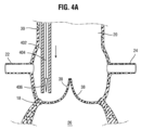
図4A~図4Gは、縫合糸を使用して弁尖を折り畳むおよび/または捕獲するための例示的な方法を図示している。図4Aに示されているように、送達カテーテル402は、上行大動脈20から既存の弁構造体(たとえば、図示されている例における天然の大動脈弁、または、図示されていない例における以前に据え付けられた人工心臓弁)の弁尖38のうちの1つに向けて前進され得る。たとえば、送達カテーテル402は、その端部が弁尖38のうちの1つの第1の部分に面した状態で位置決めされ得る。第1の部分は、弁尖38の自由端部42よりも弁輪18の近くにあることが可能であり、好ましくは、冠状動脈22の口に対して遠位にある。いくつかの実施形態において、弁尖38の第1の部分は、冠状動脈22の口と円周方向に整合され得る(たとえば、上行大動脈20から見たときに、既存の弁構造体の中心から延在する同じ半径方向のベクトルに沿って整合されているかまたは実質的に整合されている)。
FIGS. 4A-4G illustrate exemplary methods for folding and/or capturing valve leaflets using sutures. As shown in FIG. 4A, the
縫合糸404がそれに取り付けられた状態の針406は、送達カテーテル402の中に配設され得る。送達カテーテル402が弁尖38の第1の部分に隣接して配設されると、針406は、送達カテーテル402の遠位端部から前進され、弁尖38の第1の部分408を穿孔することが可能である。したがって、縫合糸404を備えた針406は、図4Bに示されているように、第1の部分408を通って弁尖38の遠位側へ移動する。次いで、縫合糸404は、既存の弁構造体の弁尖38の自由端部42間の中央ギャップ410を通して針406を移動させることによって、弁尖38の近位側へ引っ張り戻され得る。次いで、中央ギャップ410を通過した縫合糸404の一部分404bは、弁尖38の第1の部分408を通過していない縫合糸404の一部分404aの上に結ばれ得る。
A
ノット412は、図4Cに示されているように、部分404bを部分404aに結ぶことによって形成される。ノット412および縫合糸部分404a、404bは、ループ414を画定しており、ループ414は、第1の部分408と弁尖自由端部42との間の弁尖38の一部を取り囲んでいる。ノット412は、縫合糸404に沿ってスライド可能となるように形成され得る。いくつかの実施形態において、ノット412自身の構成は、たとえば、スリップノットまたは他のスライド式のノットを形成することによって、それが縫合糸404に沿ってスライド可能になることを可能にする。代替的にまたは追加的に、ノット412は、ノット412が縫合糸404に沿ってスライドすることを可能にするように、最初に緩い状態で形成され得る。したがって、ノット412は、縫合糸404に沿って弁構造体に向けて遠位にスライドされ得、ループ414のサイズを低減させるようになっている。ループ414のサイズの低減は、図4Dに示されているように、その中に含まれる弁尖のパーツ(すなわち、その自由端部42と穿孔された第1の部分408との間の弁尖38の一部)をそれ自体の上にカールさせるまたは折り畳ませる。
A
いくつかの実施形態において、ノット412を弁構造体に向けて遠位にスライドさせることは、ノット412および縫合糸404のうちの少なくとも一方を他方に対して移動させることによって実現され得る。たとえば、縫合糸404は、近位方向に引っ張られ得、それは、ループ414を締め付け、ノット412を遠位に移動させることが可能である。代替的にまたは追加的に、ノット412は、プッシュ/アシスト部材によって、たとえば、図4Eに示されているようなスライド部材416によって、弁尖38の穿孔された第1の部分408に向けて遠位方向に押され得る。代替的にまたは追加的に、ノット412は、縫合糸404が近位方向に後退されるときに、プッシュ/アシスト部材(たとえば、位置決め部材)によって適切な場所に保持され得る。スライド部材416は、縫合糸404がそれを通って延在する貫通孔部、導管、または凹部を有することが可能であり、また、スライド部材416がノット412と接触させられるときにノット412に当接するように構築された一部分(たとえば、遠位端部)を有することが可能である。たとえば、スライド部材416は、送達カテーテル402の中の縫合糸404の上に最初に配設され得、スライド部材416は、送達カテーテル402の遠位端部から上行大動脈20の中へ送達されるようにサイズ決めおよび形状決めされ得る。代替的に、プッシュ/アシスト部材は、別個の部材416ではなく、送達カテーテル402の遠位端部部分であることが可能である。
In some embodiments, sliding
ループ414のサイズの低減の量は、その中に含まれている弁尖38の折り畳まれたパーツが、既存の弁構造体の中への人工心臓弁のその後の装着によって半径方向外向きに押圧されるときでも、冠状動脈22の口に対して遠位に位置決めされるように選ばれ得る。縫合糸ループ414のサイズの十分な低減が実現されると、ノット412は、図4Fに示されているように、適切な場所にロックされ得る。ノット412のロッキングは、弁尖38の捕獲されたパーツが、人工心臓弁の据え付けの間にまたはその後に広がらないことを保証することが可能である。たとえば、ノット412は、ノット自身の操作によって(たとえば、ノット412を締め付けること、および/または、ノット412を形成する縫合糸部分を結合させること、融合させること、もしくは固めることなどによって)、適切な場所にロックされ得る。代替的にまたは追加的に、ノット412は、ノット412と接触させられる別個の物理的なデバイス418によって、適切な場所にロックされ得る。いくつかの実施形態において、スライド部材416は、ロッキングデバイス418をノット412に対して適切な場所に位置決めするために使用され得る。ロッキングデバイス418は、スライド構成(たとえば、スライド構成では、貫通孔部が、縫合糸404とロッキングデバイス418との間の相対運動を許容する)と非スライド構成(たとえば、非スライド構成では、貫通孔部が、たとえば、貫通孔部の側壁部と接触するように縫合糸404を押圧する部材によって、縫合糸404とロッキングデバイス418との間の相対運動を制限する)との間で再構成するように構築され得る。代替的にまたは追加的に、ロッキングデバイス418は、たとえば、米国特許出願公開第2018/0177503号および同第2020/0000458号に説明されているように、縫合糸クリップまたは締結具を含み、それらの文献のすべては、参照により本明細書に組み込まれている。ノット412が適切な場所にロックされた状態で、縫合糸404は、図4Fに示されているように、(たとえば、ロッキングデバイス418の直ぐ隣の場所において、または、ノット412の場所に対して近位にある別の場所において)カットされ、送達カテーテル402の中へ後退され得る。縫合糸404をカットすることは、カッティングツールによって行われ得、カッティングツールは、送達カテーテル402の遠位端部から提供されるか、または、上行大動脈20の中の別個のカテーテルを介して提供される。代替的に、送達カテーテル402の一部(たとえば、カテーテル402の遠位端部)は、縫合糸404をカットするためのカッティングエレメントを含むことが可能である。
The amount of reduction in the size of
したがって、縫合糸ループ414は、弁尖38のパーツを折り畳み、冠状動脈22の遠位にそれを捕獲し、それによって、冠状動脈22の口の閉塞のリスクを防止するかまたは少なくとも低減させる。たとえば、冠状動脈24の口の閉塞を防止するか、または、そのリスクを少なくとも低減させるために、既存の弁構造体の1つまたは複数の弁尖38の追加的な捕獲/折り畳みが望まれる場合には、図4A~図4Fの技法が、同じ送達カテーテル402または異なる送達カテーテルを使用して、次の弁尖38に関して同様の様式で繰り返され得る。そのような繰り返しにおいて、次の弁尖38の部分(それは、針406および縫合糸404によって穿孔されている)が、冠状動脈24の口と円周方向に整合され得る(たとえば、上行大動脈20から見たときに、既存の弁構造体の中心から延在する同じ半径方向のベクトルに沿って整合されているかまたは実質的に整合されている)。上記に詳細に議論されていないが、患者の解剖学的構造の中での針406および/もしくは縫合糸404の操作、プッシュ/アシスト部材(たとえば、スライド部材416)もしくはロッキングデバイス418の移動、ならびに/または、(たとえば、ノットを移動させるかもしくはロックするための)ノット412の操作は、腹腔鏡のおよび/または経カテーテルの心臓外科手術において用いられる任意のツール(たとえば、それに限定されないが、ノットプッシャー、縫合糸カッター、およびマニピュレーターなど)を使用して実施され得る。
さらなる弁尖捕獲が望まれないときには、クリンプされた状態にある新しい人工心臓弁が、その後に、弁尖38が捕獲された状態で、既存の弁構造体に前進され得る。たとえば、図4Gに示されているように、新しい人工弁10(それは、図2Aの弁10であるかまたは異なる人工弁であることが可能である)は、送達装置450のバルーンの上に半径方向にクリンプされ得る。送達カテーテル450は、大動脈を通して天然の大動脈弁に向けて前進され、弁尖38間に人工弁10を位置決めすることが可能である。次いで、新しい人工弁10は、送達カテーテルのバルーンを膨張させることによって拡張され、捕獲された弁尖38が新しい弁フレームの外部表面の上に配設されるようになっている。しかし、ロックされた縫合糸ループ414は、捕獲された弁尖38を、冠状動脈22、24の遠位にある場所に保ち、それによって、心臓弁植え込みが完了すると、新しい人工弁の流出端部から冠状動脈22、24へ血液が流れることを可能にする。送達装置を使用して人工弁を植え込むための送達装置および方法のさらなる詳細は、米国特許第7,780,723号、同第9,061,119号、および同第9,339,384号、ならびに米国特許出願公開第2017/0065415号に開示されており、それらの文献のすべては、参照により本明細書に組み込まれている。
When no further leaflet capture is desired, a new prosthetic heart valve in its crimped state can then be advanced over the existing valve structure with the
他の実施形態において、人工弁10は、米国特許出願公開第2014/0343670号および米国特許第8,652,202号に開示されているものなどのように、送達装置のカプセルまたは送達シースの中に半径方向に圧縮された状態で保たれる自己拡張可能な人工弁であることが可能であり、それらの文献のすべては、参照により本明細書に組み込まれている。人工弁が弁尖38間に位置決めされると、人工弁は、送達シースから展開され得、それは、人工弁が弁尖に対抗して半径方向に拡張された状態に自己拡張することを可能にする。
In other embodiments, the
他の実施形態において、人工弁10は、米国特許出願公開第2018/0153689号、米国出願第62/990,299号および国際出願第PCT/US2020/063104号に開示されているものなどのような、送達装置の1つまたは複数の機械的なアクチュエータに解放可能に接続されている機械的に拡張可能な人工弁であることが可能であり、それらの文献のすべては、参照により本明細書に組み込まれている。人工弁は、送達装置(随意的に、送達シースの中にある)によって半径方向に圧縮された状態に保たれ、弁尖38間に位置決めされる。位置決めされると、人工弁は、送達シースから展開され、また、送達装置の1つまたは複数の機械的なアクチュエータを作動させることによって、弁尖に対抗して半径方向に拡張された状態に半径方向に拡張され得る。
In other embodiments, the
いくつかの実施形態において、第1の部材(たとえば、縫合糸、ワイヤ、糸、または他の構造体)は、弁尖の第1の部分に係留されており、第2の部材(たとえば、縫合糸、ワイヤ、糸、または他の構造体)は、弁尖の第2の部分に係留されている。弁尖の第2の部分は、弁尖の自由端部の近くにあることが可能であり、一方では、弁尖の第1の部分は、弁尖のベースまたはアンカー部分(たとえば、弁尖の最も遠位のパーツ)の近くにあることが可能である。第1および第2の部材は、1つまたは複数のアンカーまたはプリケーション(plication)によって、それぞれの第1および第2の部分に係留され得る。第1および第2の部材を互いに向けて引っ張ることによって、弁尖の第2の部分は、弁尖の第1の部分に向けて引っ張られ、それによって、第1の部分と第2の部分との間に弁尖のパーツを折り畳む。弁尖の十分な折り畳みが実現されると(たとえば、人工心臓弁が既存の弁構造体の中に据え付けられたときに冠状動脈の口を閉塞させることとはならない、サイズの低減および/または場所)、第1および第2の部材の互いに対する場所は、弁尖の折り畳まれた構成を保つようにロックされ得、新しい人工心臓弁がその後に据え付けられ得る。 In some embodiments, a first member (eg, suture, wire, thread, or other structure) is anchored to the first portion of the leaflet and a second member (eg, suture A thread, wire, thread, or other structure) is anchored to the second portion of the leaflet. The second portion of the leaflet can be near the free end of the leaflet, while the first portion of the leaflet is the base or anchor portion of the leaflet (e.g., the base or anchor portion of the leaflet). most distal part). The first and second members may be anchored to their respective first and second portions by one or more anchors or applications. By pulling the first and second members toward each other, the second portion of the leaflet is pulled toward the first portion of the leaflet, thereby separating the first portion and the second portion. Fold the leaflet parts between Once sufficient leaflet folding is achieved (e.g., a reduced size and/or location that will not result in occlusion of the coronary ostia when the prosthetic heart valve is installed within an existing valve structure). ), the location of the first and second members relative to each other can be locked to preserve the folded configuration of the leaflets, and a new prosthetic heart valve can be subsequently installed.
図5A~図5Hは、係留された縫合糸を使用して弁尖を折り畳むおよび/または捕獲するための例示的な方法を図示している。図5Aに示されているように、送達カテーテル502は、上行大動脈20から既存の弁構造体(たとえば、図示されている例における天然の大動脈弁、または、図示されていない例における以前に据え付けられた人工心臓弁)の弁尖38のうちの1つに向けて前進され得る。たとえば、送達カテーテル502は、その端部が弁尖38のうちの1つの第1の部分に面した状態で位置決めされ得る。第1の部分は、弁尖38の自由端部42よりも弁輪18の近くにあることが可能であり、好ましくは、冠状動脈22の口に対して遠位にある。いくつかの実施形態において、弁尖38の第1の部分は、冠状動脈22の口と円周方向に整合され得る(たとえば、上行大動脈20から見たときに、既存の弁構造体の中心から延在する同じ半径方向のベクトルに沿って整合されているかまたは実質的に整合されている)。
FIGS. 5A-5H illustrate exemplary methods for folding and/or capturing leaflets using tethered sutures. As shown in FIG. 5A,
第1の縫合糸504がそれに取り付けられた状態の針506は、送達カテーテル502の中に配設され得る。送達カテーテル502が弁尖38の第1の部分に隣接して配設されると、針506は、送達カテーテル502の遠位端部から前進され、弁尖38の第1の部分508を穿孔することが可能である。したがって、第1の縫合糸504を備えた針506は、図5Bに示されているように、第1の部分508を通って弁尖38の遠位側へ移動する。第1の部分508において、少なくとも1つのアンカーが、第1の縫合糸504を弁尖38に係留するために形成され得る。たとえば、遠位側アンカー510が、第1の部分508に形成され得る。代替的にまたは追加的に、近位側アンカー512が、第1の部分508に形成され得る。図5Cに示されているように、第1の縫合糸504は、遠位側アンカー510と近位側アンカー512との間に延在することが可能である。
A
たとえば、それぞれのアンカー510、512は、第1の縫合糸504のノット付き部分、布もしくはファブリックのピース、弁尖から形成されたプリケーション、および/またはロッキング部材を含むことが可能である。遠位側アンカーを形成するために、アンカー固定コンポーネント(たとえば、ファブリック、クリップなど)が、縫合糸によって弁尖の穿孔された部分を通過され得、遠位側において拡張され得る。近位側アンカーを形成するために、アンカー固定コンポーネントは、たとえば、送達カテーテルから縫合糸をスライドさせて落とすことによって、弁尖の近位側表面に搬送され得る。たとえば、それぞれのアンカー510、512は、米国特許出願公開第2018/0177503号および同第2020/0000458号に開示されている縫合糸締結具または縫合糸クリップのうちの1つまたは複数を含むことが可能であり、それらの文献のすべては、参照により本明細書に組み込まれている。弁尖への縫合糸取り付けのさらなる詳細は、米国特許出願公開第2015/0230919号に見出され得、その文献も、参照により本明細書に組み込まれている。
For example, each
図5Dに示されているように、別の送達カテーテル520が、上行大動脈20から前進され、その遠位端部が同じ弁尖38の第2の部分に面した状態で位置決めされ得る。第2の部分は、第1の部分508よりも弁尖38の自由端部42の近くにあることが可能である。いくつかの実施形態において、弁尖38の第2の部分も、冠状動脈22の口と円周方向に整合され得る(たとえば、上行大動脈20から見たときに、既存の弁構造体の中心から延在する同じ半径方向のベクトルに沿って整合されているかまたは実質的に整合されている)。第2の縫合糸514がそれに取り付けられた状態の別の針516が、送達カテーテル520の中に配設され得る。送達カテーテル520が弁尖38の第2の部分に隣接して配設されると、針516は、送達カテーテル502の遠位端部から前進され、弁尖38の第2の部分518を穿孔することが可能である。したがって、第2の縫合糸514を備えた針516は、図5Eに示されているように、第2の部分518を通して弁尖38の遠位側へ移動する。
Another
第2の部分518において、少なくとも1つのアンカーが、第2の縫合糸514を弁尖38に係留するために形成され得る。たとえば、遠位側アンカー522が、第2の部分518に形成され得る。代替的にまたは追加的に、近位側アンカー524が、第2の部分518に形成され得る。図5Fに示されているように、第2の縫合糸514は、遠位側アンカー522と近位側アンカー524との間に延在することが可能である。アンカー510、512と同様に、それぞれのアンカー522、524は、第1の縫合糸504のノット付き部分、弁尖から形成されたプリケーション、および/またはロッキング部材であることが可能であり、ならびに/または、縫合糸締結具もしくは縫合糸クリップのうちの1つまたは複数を用いることが可能である。送達カテーテル502の位置決め、および、第1の部分508におけるアンカー510、512の形成の後に、送達カテーテル520の位置決め、および、第2の部分518におけるアンカー522、524の形成が説明されてきたが、そのような説明は、単に便宜上のためのものである。実際に、図5A~図5Fに関して上記に説明されているステップは、同時に起こるか、または、説明されているものとは異なる順序で起こることが可能である。
At least one anchor may be formed in
縫合糸504、514が、それらのそれぞれのアンカーによって、弁尖38の第1の部分508および第2の部分518に係留されると、送達カテーテル502、520が後退され得、図5Gに示されているように、連結部材530が提供され得、それは、たとえば、上行大動脈を通して縫合糸504、514の上を挿入される別のカテーテルを介して送達され得る。連結部材530は、1つまたは複数の貫通孔部、導管、または凹部を有することが可能であり、縫合糸504、514がそれを通って延在する。たとえば、連結部材530は、1対の貫通孔部532、534を備えたスライド部材であることが可能である。第1の縫合糸504は、第1の貫通孔部532を通って延在することが可能であり、一方では、第2の縫合糸514は、第2の貫通孔部534を通って延在することが可能である。貫通孔部532、534の間の横方向の距離は、弁尖38の輪郭に沿った第1の部分508と第2の部分518との間の距離よりも小さくなっていることが可能である。したがって、連結部材530が上行大動脈20から弁尖38に向けて遠位に前進されるとき、貫通孔部532、534の間の間隔が、弁尖38の第1および第2の部分508、518を互いに向けて引っ張り、それによって、弁尖38を折り畳ませる。とりわけ、アンカー固定された部分526(たとえば、弁輪18の最も近く)とアンカー固定された部分528(たとえば、自由端部42の最も近く)との間の弁尖のパーツ538は、それ自体の上に折り畳み、図5Hに図示されているように、アンカー510/512とアンカー522/524との間に波形の構成を有するか、または、少なくとも冠状動脈22から離れるように遠位に延在することが可能である。代替的に、連結部材は、単一の貫通孔部を備えたスライド部材であることが可能である。第1および第2の縫合糸504、514の両方が、同じ貫通孔部を通って延在することが可能である。貫通孔部の遠位端部の横方向の寸法(たとえば、直径)は、弁尖38の輪郭に沿った第1の部分508と第2の部分518との間の距離よりも小さくなっていることが可能である。したがって、連結部材が弁尖38に向けて前進されるときに、貫通孔部の側壁部は、弁尖38の第1および第2の部分508、518を互いに向けて引っ張り、それによって、弁尖38を折り畳ませる。
Once the
いくつかの実施形態において、第1の縫合糸504を弁尖38の第1の部分508に係留するために使用される送達カテーテル502は、第2の縫合糸514を第2の部分518に係留するために使用されるものと同じであることが可能である。たとえば、第1の部分508にアンカー510、512を形成した後に、縫合糸504は、送達カテーテル502の遠位端部とアンカー512との間の場所においてカットされ得、縫合糸504の切断されたパーツは、連結部材によるその後の使用のために保たれ得る。したがって、送達カテーテル502は、(たとえば、図5Fの送達カテーテル520のように)第2の部分518に対して自由に再位置決めすることができる。代替的に、第1の部分508においてアンカー510、512を形成した後に、第1の縫合糸504は、第2の部分518に対する再位置決めの間に、送達カテーテル502の端部から延在するように維持される。第2の針516および第2の縫合糸514は、送達カテーテル502から延在させられ得、一方では、第1の縫合糸504は、第1の部分508とカテーテル502との間に延在し続ける。そのような構成では、送達カテーテル502は、アンカー522、524を形成した後に第1の部分508および第2の部分518を一緒に引っ張るための「単一の貫通孔部」の連結部材として使用され得る。
In some embodiments, the
連結部材530が近位側アンカー512、524と接触した状態になると、および/または、弁尖がその他の方法で十分な折り畳みを実現したときに(既存の弁構造体の中への人工心臓弁のその後の装着によって半径方向外向きに押圧されるときでも、折り畳まれた弁尖38は、冠状動脈22の口に対して遠位に位置決めされる)、連結部材530は、図5Hに示されているように、アンカー固定された部分526、528に対して適切な場所にロックされ得る。連結部材530のロッキングは、弁尖38の折り畳まれたパーツが、人工心臓弁の据え付けの間にまたはその後に広がらないことを保証することが可能である。たとえば、連結部材530は、連結部材530の近位側と接触させられる別個の物理的なデバイス536によって、適切な場所にロックされ得る。代替的にまたは追加的に、連結部材530は、スライド構成(たとえば、スライド構成では、貫通孔部532、534が、縫合糸504、514と連結部材530との間の相対運動を許容する)と非スライド構成(たとえば、非スライド構成では、それぞれの貫通孔部532、534が、たとえば、それぞれの貫通孔部の側壁部と接触するように縫合糸504、514を押圧する部材によって、縫合糸504、514と連結部材530との間の相対運動を制限する)との間で再構成するように構築され得る。代替的にまたは追加的に、連結部材530は、縫合糸自身の操作によって、適切な場所にロックされ得る。たとえば、連結部材530の近位側から延在する縫合糸504、514の自由端部は、連結部材を適切な場所にロックするために、(たとえば、結ぶこと、結合させること、融合させること、または固めることによって)一緒に接合され得る。
Once the connecting
連結部材530が適切な場所にロックされた状態で、それぞれの縫合糸504、514は、図5Hに示されているように、(たとえば、ロッキングデバイス536の直ぐ隣の場所において、または、連結部材の場所に対して近位にある別の場所において)カットされ、近位に後退され得る。それぞれの縫合糸504、514をカットすることは、カッティングツールによって行われ得、カッティングツールは、いずれかの送達カテーテル502、520の遠位端部から提供されるか、または、上行大動脈20の中の別個のカテーテルを介して提供される。代替的に、送達カテーテル502、520のうちの一方または両方の一部(たとえば、カテーテル502、520の遠位端部)は、それぞれの縫合糸504、514をカットするためのカッティングエレメントを含むことが可能である。
With
したがって、互いに向けて引っ張られたアンカー固定された部分526、528は、弁尖パーツ538を捕獲して折り畳み、弁尖自由端部42を冠状動脈22の遠位に位置決めし、それによって、冠状動脈22の口の閉塞のリスクを防止するかまたは少なくとも低減させる。たとえば、冠状動脈24の口の閉塞を防止するか、または、そのリスクを少なくとも低減させるために、既存の弁構造体の1つまたは複数の弁尖38の追加的な捕獲/折り畳みが望まれる場合には、図5A~図5Hの技法が、同じ送達カテーテル502、520または異なる送達カテーテルを使用して、次の弁尖38に関して同様の様式で繰り返され得る。そのような繰り返しにおいて、次の弁尖38の部分(それらは、針506および516によってそれぞれ穿孔されている)が、冠状動脈24の口と円周方向に整合され得る(たとえば、上行大動脈20から見たときに、既存の弁構造体の中心から延在する同じ半径方向のベクトルに沿って整合されているかまたは実質的に整合されている)。上記に詳細に議論されていないが、患者の解剖学的構造の中での針506、516および/または縫合糸504、514の操作、アンカー510、512、522、524を形成もしくは据え付けること、および/または、連結部材530もしくはロッキングデバイス536の移動は、腹腔鏡のおよび/または経カテーテルの心臓外科手術において用いられる任意のツール(たとえば、それに限定されないが、縫合糸カッター、およびマニピュレーターなど)を使用して実施され得る。
Accordingly, the anchored
さらなる弁尖捕獲/折り畳みが望まれないときには、クリンプされた状態にある新しい人工心臓弁が、その後に、(たとえば、図4Gに示されているように)弁尖38が捕獲された状態で、既存の弁構造体に前進され得る。新しい弁は、弁構造体の中に配設されて拡張され、捕獲された弁尖38が新しい弁フレームの外部表面の上に配設されるようになっている。しかし、近接したアンカー固定された部分526、528は、冠状動脈22、24の遠位にある位置において弁尖38を保ち、それによって、心臓弁植え込みが完了すると、新しい人工弁の流出端部から冠状動脈22、24へ血液が流れることを可能にする。
When no further leaflet capture/folding is desired, the new prosthetic heart valve in its crimped state is then placed with the
いくつかの実施形態において、ロッキングデバイスは、折り畳まれた構成で、および、対応する冠動脈口を閉塞させることを回避する位置において、弁尖を捕獲するために使用され得る。ロッキングデバイスは、弁尖の自由端部の上に開いた構成で前進され得る。ロッキングデバイスの一部分、または、そのアクチュエータの一部分は、ロッキングデバイスが弁尖の上にさらに前進されるときに、ロッキングデバイスの対向する部材の間に弁尖のパーツを収集することが可能である。弁尖の十分なパーツが収集されると(たとえば、人工心臓弁が既存の弁構造体の中に据え付けられたときに、そうでなければ冠状動脈の口を閉塞させることとはならない、サイズの低減および/または場所)、ロッキングデバイスは、閉じた構成に移行することが可能であり、閉じた構成では、ロッキングデバイス部材が互いに接近し、弁尖の収集されたパーツに接触してそれらの間に保ち、新しい人工心臓弁がその後に据え付けられ得る。 In some embodiments, locking devices can be used to capture leaflets in a collapsed configuration and in a position that avoids occluding the corresponding coronary ostia. The locking device may be advanced in an open configuration over the free ends of the leaflets. A portion of the locking device, or a portion of its actuator, can collect leaflet parts between opposing members of the locking device as the locking device is advanced further over the leaflets. Once enough parts of the leaflet have been collected (e.g., when a prosthetic heart valve is installed in an existing valve structure, it is of a size that would not otherwise occlude the ostium of the coronary artery). reduction and/or location), the locking device is allowed to transition to a closed configuration in which the locking device members are brought closer together to contact the collected parts of the leaflets and move them between them. and a new heart valve prosthesis can be installed thereafter.
図6A~図6Bは、例示的なロッキングデバイスを図示しており、図6C~図6Eは、例示的なロッキングデバイスを使用して弁尖を折り畳むおよび/または捕獲するための例示的な方法を図示している。とりわけ、図6Aは、開いた構成にあるロッキングデバイス600を図示しており、図6Bは、閉じた構成にあるロッキングデバイス600を図示している。ロッキングデバイス600は、第1の部材602および第2の部材614を有することが可能である。開いた構成では、第1の部材602は、第2の部材614から間隔を置いて配置され、その間にギャップ620を画定する。閉じた構成では、第1の部材602および第2の部材614は、互いに接近しており、ギャップ620を排除するか、または、ギャップ620のサイズを少なくとも低減させる。第1の部材602は、メス型部材として構築され、たとえば、1つまたは複数の凹部604を有することが可能である。第2の部材614は、オス型部材、たとえば、1つまたは複数の突出部または歯先616として構築され得る。それぞれの突出部616は、凹部604のうちの1つに対応しており、突出部616は、開いた構成では、対応する凹部604から間隔を置いて配置され、それと整合されており、突出部616は、閉じた構成では、対応する凹部604の一部分の中へ挿入され、それと接触している。それぞれの突出部616は、鋭い先端部を有することが可能であり、鋭い先端部は、ロッキングデバイス600が開いた構成から閉じた構成へ移行するときに、ギャップ620の中の弁尖を穿孔するように構築されている。
6A-6B illustrate an exemplary locking device and FIGS. 6C-6E illustrate an exemplary method for folding and/or capturing leaflets using an exemplary locking device. Illustrated. In particular, Figure 6A illustrates locking
突出部616および凹部604は、たとえば、閉じた構成において突出部616が凹部604の中へ挿入されたときに、凹部604からの突出部616の除去を防止するために、1つまたは複数のスナップフィット特徴を備えて構築され得る。たとえば、突出部616は、返し付き部分618を含むことが可能であり、凹部604は、その中にリッジ部606を含むことが可能である。ロッキングデバイス600が閉じた構成に移行するときに、突出部616は、凹部604の中へ挿入され、返し付き部分618の縁部が、リッジ部606に当接し、凹部604からの突出部616の引き出しに抵抗するようになっている。いくつかの実施形態において、たとえば、第1の部材602と第2の部材614との間の弁尖の収集された部分に関する厚さの変動に対処するために、突出部616は、複数の返し付き部分を含む。凹部604と突出部616との間のスナップフィットロッキング特徴に加えて、または、その代わりに、ロッキングデバイス600は、1つまたは複数の外部ロッキング特徴(たとえば、それに限定されないが、たとえばギャップ620に隣接して部材602、614の外部部分の上に配設されているリニアラチェットなど)を含むことが可能である。そのような代替的な構成では、リニアラチェットは、下記にさらに説明されているように、収集部材として使用され得る。
1つの突出部616および1つの凹部604のみが図6A~図6Bに示されているが、開示されている主題の実施形態は、それに限定されない。むしろ、第2の部材614は、複数の別個の突出部616を有することが可能であり、第1の部材602は、複数の対応する凹部604を有することが可能である。そのうえ、それぞれの部材602、614は、突出部616または凹部604のうちの一方のみを備えて図示されているが、部材602、614は、いくつかの実施形態では、両方を含むことが可能である。たとえば、第2の部材614は、突出部616に加えて、1つまたは複数の凹部を有することが可能であり、第1の部材602は、凹部604に加えて、1つまたは複数の突出部を有することが可能である。複数の突出部および凹部を備えた実施形態では、突出部-凹部の対のうちの1つ、いくつか、またはすべてが、スナップフィット特徴を含むことが可能である。
Although only one
開いた構成から閉じた構成へのロッキングデバイス600の移行は、アクチュエータによって実現され得る。たとえば、アクチュエータは、ハサミ型アクチュエータ612(たとえば、図6Aに示されているものなど)であることが可能である。アクチュエータ612は、第1の部材602の連結部分608に取り付けられている第1のアーム610と、第2の部材614の連結部分622に取り付けられている第2のアーム624とを有することが可能である。第1のアーム610および第2のアーム624は、ヒンジ626において一緒に連結され得、それは、アーム610、624が互いに対して回転することを可能にする。端部628、630における圧縮力の印加は(その力は、端部を一緒に押す)、アーム610、624をヒンジ626の周りに枢動させ、それによって、第1の部材602および第2の部材614を互いに向けて付勢する。アクチュエータアーム610、624は、それぞれの連結部分608、622に解放可能に取り付けられ得、たとえば、図6Bに示されているように、アクチュエータ612が閉じた構成で設置された後に、アクチュエータ612が、ロッキングデバイス600から除去され得るようになっている。1つまたは複数の企図された実施形態にしたがって、他の型のアクチュエータも可能である。実際に、患者の上行大動脈の中で動作することができ、凹部604と突出部616との間のアライメントを維持しながら第1および第2の部材602、614を互いに向けて制御可能に移動させることができる任意のアクチュエータが使用され得る。
Transition of locking
いくつかの実施形態において、アクチュエータ612は、ギャップ620に隣接して領域632を画定しており、領域632は、ロッキングデバイス600が弁尖の自由端部から弁輪に向けて移動されるときに、弁尖のパーツをギャップ620の中へ収集するように設計されている。たとえば、領域632は、ギャップ620に面するヒンジ626におけるアーム610、624の一部分によって形成され得る。代替的にまたは追加的に、別個の構造体(たとえば、収集部材)が、アクチュエータ612とギャップ620との間に配設され得、弁尖を収集するために使用され得る。たとえば、収集部材は、領域632において連結部分608、622の間に延在する縫合糸、ワイヤ、または糸を含むことが可能である。別の例では、収集部材は、領域632においてアクチュエータアーム610、624の間に延在するバーであることが可能であり、アクチュエータアーム610、624が互いに対して制限なしに移動することを可能にするスロットを備えている。
In some embodiments, the
図6Cに示されているように、アクチュエータ612を備えたロッキングデバイス600は、上行大動脈20から開いた構成で前進され得、既存の弁構造体(たとえば、図示されている例における天然の大動脈弁、または、図示されていない例における以前に据え付けられた人工心臓弁)の弁尖38のうちの1つに対して位置決めされるようになっている。たとえば、弁尖38の自由端部42が、第1の部材602と第2の部材614との間のギャップ620の中に配置され得る。次いで、アクチュエータ612を備えたロッキングデバイス600は、図6Dに示されているように、弁尖38に沿ってさらに前進され得る。たとえば、ロッキングデバイス600が弁輪18に向けて移動されるときに、アクチュエータ612のヒンジ626に隣接する領域632が、弁尖38の自由端部42に当接し、それをそれ自体の上に折り畳ませ、弁尖38の折り畳まれた部分634がギャップ620の中に収集されるようになっている。代替的にまたは追加的に、ギャップ620と領域632との間の収集部材は、弁尖38の自由端部42に接触することが可能であり、ロッキングデバイス600が前進されるときに、弁尖38をそれ自体の上に折り畳ませるようになっている。
As shown in FIG. 6C, locking
ロッキングデバイス前進の量は、弁尖38の折り畳まれた近位縁部636が、既存の弁構造体の中への人工心臓弁のその後の装着によって半径方向外向きに押圧されるときでも、冠状動脈22の口に対して遠位に位置決めされるように選ばれ得る。ロッキングデバイス600が弁尖の上に十分に前進されると、アクチュエータ612は、図6Eに示されているように、ロッキングデバイス600を閉じた構成に移行させるように作動され得る。したがって、第2の部材614の突出部は、第1の部材602に向けて移動し、それによって、第1の部材602の対応する凹部の中へ挿入される前に、ギャップ620の中の弁尖の折り畳まれた部分を穿孔する。閉じた構成への移行は、たとえば、上記に説明されているスナップフィット特徴のうちの1つまたは複数を介して、第1および第2の部材を一緒にさらにロックすることが可能である。ロッキングデバイスのロッキングは、弁尖38の捕獲されたパーツ634が、人工心臓弁の据え付けの間にまたはその後に広がらないことを保証することが可能である。したがって、アクチュエータ612は、ロッキングデバイス600から解放され得、その後に、ロッキングデバイスを別の弁尖の上に据え付けるために使用され得、または、そうでなければ、患者から回収され得る。
The amount of locking device advancement is coronal even when the folded
したがって、ロッキングデバイス600の据え付けは、弁尖38のパーツを折り畳み、それを冠状動脈22の遠位に捕獲し、それによって、冠状動脈22の口の閉塞のリスクを防止するかまたは少なくとも低減させる。たとえば、冠状動脈24の口の閉塞を防止するか、または、そのリスクを少なくとも低減させるために、既存の弁構造体の1つまたは複数の弁尖38の追加的な捕獲/折り畳みが望まれる場合には、図6C~図6Fの技法が、別のロッキングデバイスおよび同じアクチュエータ612または異なるアクチュエータを使用して、次の弁尖38に関して同様の様式で繰り返され得る。上記に詳細に議論されていないが、患者の解剖学的構造の中でのロッキングデバイス600および/またはアクチュエータ612の操作、アクチュエータ612の作動、および/または、アクチュエータ612の解除は、腹腔鏡のおよび/または経カテーテルの心臓外科手術において用いられる任意のツールを使用して実施され得る。
Installation of the
さらなる弁尖捕獲が望まれないときには、クリンプされた状態にある新しい人工心臓弁が、その後に、(たとえば、図4Gに示されているように)弁尖38がロッキングデバイス600によって捕獲された状態で、既存の弁構造体に前進され得る。新しい弁は、弁構造体の中に配設されて拡張され、捕獲された弁尖38が、新しい弁フレームの外部表面の上に配設されるようになっている。しかし、ロッキングデバイス600は、冠状動脈22、24の遠位にある場所において、捕獲された弁尖38を保ち、それによって、心臓弁植え込みが完了すると、新しい人工弁の流出端部から冠状動脈22、24へ血液が流れることを可能にする。
When no further leaflet capture is desired, the new prosthetic heart valve in its crimped state, with
いくつかの実施形態において、クリップ部材が、折り畳まれた構成で、および、対応する冠動脈口を閉塞させることを回避する位置において、弁尖を捕獲するために使用され得る。クリップ部材は、付勢された状態および自由状態を有することが可能である。付勢された状態では、クリップ部材の端部は、(たとえば、実質的に線形の構成を有する)クリップ部材の反対側端部において保持され得る。自由状態では、クリップ部材の端部同士は、互いに接近し、クリップ部材が少なくとも部分的に捕獲領域の境界を定めるようになっている。クリップ部材は、弁尖の自由端部の上に、付勢された状態で前進され得る。クリップ部材の一方の端部は、弁尖の遠位側に配設され得る。次いで、クリップ部材は、付勢された状態から解放され、それによって、自由状態に移行し、捕獲領域の中に弁尖のパーツを捕獲することが可能である。新しい人工心臓弁が、その後に据え付けられ得る。 In some embodiments, clip members can be used to capture leaflets in a collapsed configuration and in a position that avoids occluding the corresponding coronary ostia. The clip member can have a biased state and a free state. In the biased state, the ends of the clip member can be held at opposite ends of the clip member (eg, having a substantially linear configuration). In the free state, the ends of the clip member are close together such that the clip member at least partially delimits the capture area. The clip member may be advanced in a biased state over the free ends of the leaflets. One end of the clip member may be disposed distal to the leaflet. The clip member is then released from the biased condition thereby allowing it to transition to a free condition and capture parts of the leaflet within the capture area. A new prosthetic heart valve can then be installed.
図7Aは、自由状態にある例示的なクリップ部材を図示しており、図7B~図7Dは、例示的なクリップ部材を使用して弁尖を折り畳むおよび/または捕獲するための例示的な方法を図示している。クリップ部材700は、中間部分702によって一緒に接続されている端部706、708を有することが可能である。図7Aに図示されている自由状態では、クリップ部材700は、涙滴形状またはW字形状を有している。中間部分702は、弁尖を受け入れるための捕獲領域704を画定する湾曲した構成をとっている。端部706、708は、互いに接触しているか、または、ギャップによって互いに間隔を置いて配置され得、ギャップは、弁尖の厚さよりも小さくなるようにサイズ決めされ得る。クリップ部材700は、送達カテーテルの中へ装填するために、および、弁尖のパーツの周りに最初に位置決めするために、付勢された状態で配設され得る。図7Bに図示されている付勢された状態では、クリップ部材700の端部706、708は、引っ張り離されており、第1の端部706が、第2の端部708の側とは反対にある中間部材702の側にあるようになっている。付勢された状態では、クリップ部材700は、実質的に線形の構成または弧状の構成(たとえば、弓形状の構成)をとることが可能である。
FIG. 7A illustrates an exemplary clip member in a free state, and FIGS. 7B-7D illustrate exemplary methods for folding and/or capturing leaflets using the exemplary clip member. is illustrated.
クリップ部材700は、端部706、708を離して保持する力の解放のときに(たとえば、送達カテーテルから解放されるときに)、付勢された状態から自由状態へ自動的に移行する可撓性の材料(たとえば、スプリング金属)または形状記憶合金から形成され得る。たとえば、クリップ部材は、鋼、コバルトクロム合金、またはニッケルチタン合金(たとえば、ニチノール)から形成され得る。いくつかの実施形態において、クリップ部材700は、その1つの部分、いくつかの部分、または、すべての部分の上に、コーティングを含むことが可能である。たとえば、クリップ部材700の少なくとも一部分は、生体適合性表面コーティングを有することが可能である。代替的にまたは追加的に、端部706、708は、表面コーティングまたは表面処理を提供され、据え付けられたときの弁尖に対する保持を改善することが可能である。たとえば、表面コーティングまたは表面処理は、下層の材料の天然の状態と比較して、端部706、708の摩擦係数を増加させることが可能である。
いくつかの実施形態において、端部706から端部708へのクリップ部材の断面幾何学形状は、実質的に同じである。たとえば、クリップ部材700は、自由状態に関して適当な湾曲した形状へと形成された実質的に一定の直径の可撓性のロッドから形成され得る。他の実施形態において、少なくとも端部706、708は、異なる形状を有しており、および/または、中間部分702の材料とは異なる材料から形成されている。たとえば、端部706、708は、それらの間に弁尖を保つことを支援するようにサイズ決めまたは形状決めされ得る。図7Aの図示されている例では、端部706、708は、中間部分702の厚さよりも大きい直径を有するボールとして形状決めされている。ボール端部706、708は、クリップ部材700が自由状態に移行すると、弁尖をそれらの間に挟むように作用することが可能である。代替的にまたは追加的に、端部706、708は、磁気材料から形成され得る。自由状態において弁尖の上に配設されているときに、端部706、708は、弁尖がその間にある状態で互いに引き合うことが可能であり、その引き合う力は、弁尖へのクリップ部材700の保持を改善することが可能である。別の例では、端部706、708、および/または、端部706、708までつながるクリップ部材700の部分は、自由状態においてその上に配設されているときに弁尖に接触する、延長された平坦な領域として形成され得る。延長された平坦な領域は、接触表面積を増加させ、それによって、弁尖に対するクリップ部材700の保持を改善することが可能である。開示されている主題の1つまたは複数の実施形態にしたがって、端部706、708および/または中間部分702に関する他の形状および構成も可能である。
In some embodiments, the cross-sectional geometry of the clip member from
図7Bに示されているように、クリップ部材700は、送達カテーテル710のルーメンの中に配設され得る。送達カテーテル710のルーメンの側壁部は、端部706、708および/または中間部分702に接触し、クリップ部材700を付勢された状態に維持する付勢力を印加することが可能である。送達カテーテル710は、上行大動脈20から前進され得、既存の弁構造体(たとえば、図示されている例における天然の大動脈弁、または、図示されていない例における以前に据え付けられた人工心臓弁)の弁尖38のうちの1つに対して位置決めされるようになっている。たとえば、送達カテーテル710の遠位端部714は、図7Bに図示されているように、弁尖間の中央ギャップの中に、および、弁尖38の自由端部42に隣接して配設され得る。第1の端部706は、図7Cに図示されているように、送達カテーテル710の遠位端部714から延在させられ、弁尖38の遠位側部分716と接触した状態になることが可能である。一方、送達カテーテル710のルーメンの側壁部は、端部708と中間部分702との間に付勢力を印加し続け、付勢された状態の構成を維持することが可能である。(図7Bに示されているような)弁尖38に対する送達カテーテル710の位置決めは、送達カテーテルの端部714からの第1の端部706の延在と同時に、その前に、または、その後に起こることが可能である。
クリップ部材700は、第2の端部708が送達カテーテル710のルーメンから解放されるまで、第1の端部706が弁尖38の遠位側に接触した状態で、送達カテーテル710の端部714から前進され続けることが可能である。ルーメンがもはや付勢力を印加しない状態で、クリップ部材700は、付勢された状態から自由状態へ移行することを許容され、図7Dに示されているように、端部706、708が互いに接近した状態になる。したがって、第2の端部708は、弁輪18に向けて遠位にカールし、第1の端部706に対向する場所において、弁尖38の近位側に配設されている。クリップ部材700が自由状態に移行するときに、中間部分702は、弁尖38の近位部分(たとえば、自由端部42に隣接する部分)に接触し、それによって、近位部分をそれ自体の上に折り畳ませることおよび捕獲領域704の中に捕獲させる。クリップ部材700は、自由状態における端部706、708が互いに接触するかまたは弁尖38の厚さよりも小さいギャップだけ分離されることになるように構築され得る。したがって、クリップ部材700が弁尖38の上に自由状態で配設されているときには、端部706、708の間の弁尖38の一部分が、端部706、708によって挟まれ、クリップ部材700を適切な場所に保つ。クリップ部材700のサイズおよび/またはその位置決めは、既存の弁構造体の中への人工心臓弁のその後の装着によって半径方向外向きに押圧されるときでも、弁尖38が冠状動脈22の口に対して遠位に位置決めされるように選ばれ得る。
いくつかの実施形態において、送達カテーテル710からのクリップ部材700の展開は、展開部材712を使用して実現され得る。展開部材712は、送達カテーテル710の中を軸線方向に移動するように作動され得る可撓性のロッドであることが可能である。たとえば、展開部材712は、送達カテーテル710のルーメンの中を遠位に移動し、第2の端部708に接触し、カテーテル710の遠位端部714からクリップ部材700を押すことが可能である。別の例では、クリップ部材700は、カテーテル710を近位に後退させながら、既存の弁構造体に対する展開部材712の位置を維持することによって展開され得る。さらに別の例では、クリップ部材700は、カテーテル710の移動(たとえば、近位に後退する)および展開部材712の移動(たとえば、送達カテーテルのルーメンの中を遠位に移動する)の組合せによって展開され得る。
In some embodiments, deployment of
したがって、クリップ部材700の据え付けは、弁尖38のパーツを折り畳み、それを冠状動脈22の遠位に捕獲し、それによって、冠状動脈22の口の閉塞のリスクを防止するかまたは少なくとも低減させる。たとえば、冠状動脈24の口の閉塞を防止するか、または、そのリスクを少なくとも低減させるために、既存の弁構造体の1つまたは複数の弁尖38の追加的な捕獲/折り畳みが望まれる場合には、図7B~図7Dの技法が、別のクリップ部材を使用して、次の弁尖38に関して同様の様式で繰り返され得る。同じ送達カテーテル710および/または展開部材712が、次の弁尖38の上に別のクリップ部材を展開させるために使用され得る。たとえば、付勢された状態にある2つ以上のクリップ部材700が、同じ送達カテーテル710のルーメンの中に直列的に配設され得る。近位クリップ部材の第2の端部と接触している展開部材712は、一連のクリップ部材700を一緒に押すことが可能であり、カテーテル710の端部から順次にそれぞれのクリップ部材を展開させるようになっている。
Installation of
さらなる弁尖捕獲/折り畳みが望まれないときには、クリンプされた状態にある新しい人工心臓弁が、その後に、(たとえば、図4Gに示されているように)弁尖38がクリップ部材700によって捕獲された状態で、既存の弁構造体に前進され得る。新しい弁は、弁構造体の中に配設されて拡張され、捕獲された弁尖38が、新しい弁フレームの外部表面の上に配設されるようになっている。しかし、クリップ部材700は、冠状動脈22、24の遠位にある場所において、捕獲された弁尖38を保ち、それによって、心臓弁植え込みが完了すると、新しい人工弁の流出端部から冠状動脈22、24へ血液が流れることを可能にする。
When no further leaflet capture/folding is desired, the new prosthetic heart valve in its crimped state is then captured by clip member 700 (eg, as shown in FIG. 4G). It can be advanced over an existing valve structure while still in place. The new valve is disposed within the valve structure and expanded such that the captured
いくつかの実施形態において、クリップ部材は、折り畳まれた構成で、および、対応する冠動脈口を閉塞させることを回避する位置において、弁尖を捕獲するように塑性変形され得る。クリップ部材は、中間部分によって一緒に接続されている第1および第2の端部を有することが可能である。クリップ部材の開いた構成では、第1および第2の端部は、ギャップによって互いに間隔を離して配置され得る。クリップ部材の閉じた構成では、ギャップは、低減されるかまたは排除され得る。クリップ部材は、開いた構成で位置決めされ得、弁尖の自由端部が、ギャップを通って延在するようになっている。クリップ部材は、弁尖の遠位部分(たとえば、カスプ部分)に向けて移動され、弁尖の折り畳みを引き起こすことが可能である。次いで、アクチュエータが、圧縮力をクリップ部材に印加するために使用され得、それは、クリップ部材を閉じた構成へ塑性変形させる(たとえば、曲げる)。少なくとも弁尖の折り畳まれたパーツは、閉じた構成にあるクリップ部材によって囲まれた領域の中に捕獲され得る。新しい人工心臓弁が、その後に据え付けられ得る。 In some embodiments, the clip members can be plastically deformed to capture the leaflets in a collapsed configuration and in a position that avoids occluding the corresponding coronary ostia. The clip member can have first and second ends connected together by an intermediate portion. In the open configuration of the clip member, the first and second ends may be spaced apart from each other by a gap. In the closed configuration of the clip member, gaps may be reduced or eliminated. The clip member may be positioned in an open configuration such that the free ends of the leaflets extend through the gap. A clip member can be moved toward a distal portion (eg, a cusp portion) of the leaflet to cause folding of the leaflet. An actuator can then be used to apply a compressive force to the clip member, which plastically deforms (eg, bends) the clip member to the closed configuration. At least the folded part of the leaflet can be captured within the area surrounded by the clip member in the closed configuration. A new prosthetic heart valve can then be installed.
たとえば、図10Aは、初期構成にあるクリップ部材1000を図示しており、図10Bは、開いた構成にあるクリップ部材1000を図示しており、図10Cは、閉じた構成にあるクリップ部材1000を図示している。クリップ部材1000は、中間部分1002によって一緒に接続されている第1の端部1002aおよび第2の端部1002bを有することが可能である。図10Aに図示されている初期構成では、クリップ部材1000は、実質的に線形の形状を有しており、第1および第2の端部は、その長手方向軸線に対して中間部分1002の反対側端部にある。そのような構成は、たとえば、送達カテーテルまたはシースを介して植え込み場所にクリップ部材1000を送達するために有用である可能性がある。
For example, FIG. 10A illustrates
植え込み場所に送達されると、クリップ部材1000は、たとえば、端部1002a、1002bがギャップ1016を横切って互いに向かい合うように(たとえば、実質的にC字形状を有するように)中間部分1002を曲げることによって、図10Bの開いた構成に塑性変形させられ得る。したがって、開いた構成におけるクリップ部材1000は、部分的に囲まれたエリアまたは捕獲領域1004を画定している。代替的に、いくつかの実施形態では、クリップ部材1000は、たとえば、図10Aの線形の構成から曲げることなくC字形状を有するように中間部分1002を鋳造するか、成形するか、または、その他の方法で形成することによって、図10Bの開いた構成で最初に形成され得る。
When delivered to the implantation site, the
クリップ部材1000を図10Cの閉じた構成に移行させるために、クリップ部材1000は、アクチュエータの第1のアーム1010と第2のアーム1012との間のエリア1014の中に配設されている。アクチュエータは、クリップ部材を塑性変形させる圧縮力を印加し、第1の端部と第2の端部との間のギャップ1016が排除されるかまたは少なくとも低減されるようになっており(たとえば、弁尖の厚さよりも小さい)、それによって、捕獲領域1004をさらに囲み、弁尖のパーツをその中に捕獲する。アクチュエータは、たとえば、ピンセット、外科用トング、またはハサミ型アクチュエータ(たとえば、図6Aに図示されているアクチュエータ612と同様)であることが可能である。しかし、1つまたは複数の企図された実施形態にしたがって、他のアクチュエータも可能である。実際に、アクチュエータは、患者の上行大動脈の中で動作することができ、クリップ部材に圧縮力を印加することができる、任意のタイプのアクチュエータであることが可能である。たとえば、アーム1010、1012は、クリップ部材1000の反対側端部に連結され得、シースは、その近位端部からその遠位端部に向けてアームの上を前進され、それによって、アームを一緒に付勢し、圧縮力をクリップ部材に印加することが可能である。
To transition the
クリップ部材1000は、塑性変形させられた後にその形状を維持するのに十分なリジッド性を有する材料から形成され得る。たとえば、クリップ部材1000は、金属、金属合金、または、それらの任意の組合せ(たとえば、鋼またはコバルトクロム合金など)を含むことが可能である。いくつかの実施形態において、クリップ部材1000は、その1つの部分、いくつかの部分、または、すべての部分の上に、コーティングを含むことが可能である。たとえば、クリップ部材1000の少なくとも一部分は、生体適合性表面コーティングを有することが可能である。代替的にまたは追加的に、端部1002a、1002b(たとえば、先端部1006および/または先端部1008)は、表面コーティングまたは表面処理を提供され、据え付けられたときの弁尖に対する保持を改善することが可能である。たとえば、表面コーティングまたは表面処理は、下層の材料の天然の状態と比較して、先端部1006、1008の摩擦係数を増加させることが可能である。
いくつかの実施形態において、端部1002a、1002bの間の少なくとも中間部分の断面幾何学形状は、実質的に同じになっていることが可能である。たとえば、クリップ部材1000は、図10Aの線形の構成から図10Bの開いた構成へ塑性変形させられた実質的に一定の直径のロッドから形成され得る。いくつかの実施形態において、少なくとも端部1002a、1002bは、異なる形状を有することが可能であり、および/または、中間部分1002の材料とは異なる材料から形成されている。たとえば、端部1002a、1002bは、弁尖をその間に保つことを支援するようにサイズ決めまたは形状決めされ得る。図10A~図10Cの図示されている例では、第1の端部1002aは、第1の先端部1006を有しており、第2の端部1002bは、第2の先端部1008を有している。それぞれの先端部1006、1008は、中間部分1002から離れる方向に、鋭いポイントまたは少なくとも細くなった直径の端部へテーパー付きになっていることが可能であり、弁尖と接触するときに弁尖を通って穿孔することができるようになっている。代替的に、いくつかの実施形態では、先端部1006、1008は、ボール端部と交換され得、ボール端部は、図7Aに図示されているボール端部と同様に、クリップ部材1000が閉じた構成にあるときに、弁尖をそれらの間に挟むように作用する。代替的にまたは追加的に、先端部1006、1008および/または端部1002a、1002bは、磁気材料から形成され得る。開いた構成において弁尖の上に配設されているときに、磁気材料は、弁尖がその間にある状態で互いに引き合うことが可能であり、その引き合う力は、弁尖へのクリップ部材1000の保持を改善することが可能である。開示されている主題の1つまたは複数の実施形態にしたがって、端部1002a、1002bおよび/または中間部分1002に関するさらなる形状および構成も可能である。
In some embodiments, the cross-sectional geometry of at least the intermediate portion between
図11Aに示されているように、アクチュエータアーム1010、1012は、既存の弁構造体(たとえば、図示されている例における天然の大動脈弁、または、図示されていない例における以前に据え付けられた人工心臓弁)の弁尖38aのうちの1つに対して位置決めされるように、クリップ部材を開いた構成で上行大動脈20から前進させるために使用され得る。たとえば、弁尖38aの自由端部1018が、図11Bに示されているように、第1の先端部1006と第2の先端部1008との間でギャップ1016を通って捕獲領域1004の中へ延在するように配置され得る。次いで、アクチュエータアーム1010、1012が、図11Cに示されているように、弁尖38aに沿って、クリップ部材をさらに前進させるために使用され得る。たとえば、クリップ部材が弁尖38aの遠位部分(たとえば、弁尖の根元部もしくはカスプ領域、または、弁構造体の弁輪)に向けて移動されるときに、クリップ部材の中間部分1002が、弁尖38aの自由端部1018に当接し、それをそれ自体の上に折り畳ませ、弁尖38aの折り畳まれた部分が、ギャップ1016の中に収集されるようになっている。
As shown in FIG. 11A, the
クリップ部材前進の量は、折り畳まれた弁尖38aが、既存の弁構造体の中への人工心臓弁のその後の装着によって半径方向外向きに押圧されるときでも、冠状動脈22の口に対して遠位に位置決めされるように選ばれ得る。クリップ部材が弁尖の上に十分に前進されると、アクチュエータは、アーム1010とアーム1012との間に圧縮力を印加するように作動され、それによって、図11Dに示されているように、クリップ部材を閉じた構成に塑性変形させることが可能である。したがって、クリップ部材の先端部1006、1008は、互いに向けて移動し、それらの間の弁尖38aの一部分を穿孔するか、または、それを少なくともクランプする。クリップ部材の塑性変形は、弁尖38aに対して適切な位置に先端部1006、1008をロックするために効果的である可能性がある。次いで、アクチュエータは、クリップ部材から解放され得、その後に別の弁尖の上にクリップ部材を据え付けるために使用され得るか、または、そうでなければ患者から回収され得る。アクチュエータの除去後に、クリップ部材は、図11Eに示されているように、折り畳まれた弁尖38aの上の適切な場所に残っている。したがって、クリップ部材の塑性変形は、領域1004の中に捕獲された弁尖38aのパーツが、人工心臓弁の据え付けの間にまたはその後に広がらないことを保証することが可能である。
The amount of clip member advancement is such that the folded
図示の明確化のために、アクチュエータアーム1010、1012の一部分のみが、図11A~図11Dに示されていることを理解されたい。しかし、実戦的な実施形態では、アクチュエータは、図示されていない追加的な部分、たとえば、(たとえば、ハサミ型アクチュエータのための)ヒンジセクション、(たとえば、ピンセットまたは外科用トングのための)ジョイントセクション、および/または、(たとえば、アームを一緒に付勢する力を提供するためにアームの上に前進されるシースのための)送達カテーテルもしくはシースなどを含むことになる。そのうえ、1つもしくは複数の送達カテーテルまたはシースは、クリップ部材およびアクチュエータを上行大動脈に送達するために提供され得、ならびに/または、上行大動脈の中でのアクチュエータの動作のために提供され得る。
It should be understood that only a portion of the
したがって、クリップ部材の据え付けは、弁尖38aのパーツを折り畳み、それを冠状動脈22の遠位に捕獲し、それによって、冠状動脈22の口の閉塞を防止するか、または、そのリスクを少なくとも低減させる。たとえば、冠状動脈24の口の閉塞を防止するか、または、そのリスクを少なくとも低減させるために、既存の弁構造体の1つまたは複数の弁尖38の追加的な捕獲/折り畳みが望まれる場合には、図11A~図11Eの技法が、別のクリップ部材および同じアクチュエータ(たとえば、アーム1010、1012)または異なるアクチュエータを使用して、次の弁尖38に関して同様の様式で繰り返され得る。上記に詳細に議論されていないが、患者の解剖学的構造の中でのクリップ部材1000および/もしくはアクチュエータの操作、クリップ部材1000を物理的に塑性変形させるためのアクチュエータの作動、ならびに/または、クリップ部材1000からのアクチュエータの解除は、腹腔鏡のおよび/または経カテーテルの心臓外科手術において用いられる任意のツールを使用して実施され得る。
Installation of the clip member thus folds part of the
さらなる弁尖捕獲/折り畳みが望まれないときには、クリンプされた状態にある新しい人工心臓弁が、その後に、弁尖38がクリップ部材1000によって捕獲された状態で、既存の弁構造体に前進され得る。新しい弁は、弁構造体の中に配設されて拡張され、捕獲された弁尖38が、新しい弁フレームの外部表面の上に配設されるようになっている。しかし、クリップ部材は、冠状動脈22、24の遠位にある場所において、捕獲された弁尖38を保ち、それによって、心臓弁植え込みが完了すると、新しい人工弁の流出端部から冠状動脈22、24へ血液が流れることを可能にする。
When no further leaflet capture/folding is desired, the new prosthetic heart valve in its crimped state can then be advanced over the existing valve structure with the
いくつかの実施形態において、冠状動脈の口の下方に弁尖を一時的に折り畳むために、ならびに、人工心臓弁が既存の弁構造体の中に位置決めされてその中で少なくとも部分的に拡張され得るまで、それを適切な場所に保持するために、ツールが使用され得る。人工心臓弁が拡張するときに、折り畳まれた弁尖は、周囲の解剖学的構造(たとえば、大動脈壁)または既存の構造体(たとえば、以前に植え込まれた人工弁の弁フレーム壁部)に向けて、それと接触するように、弁フレーム壁部によって押される。人工心臓弁の完全な拡張の前に(たとえば、弁フレームと周囲の構造体との間の環状の領域のサイズが、ツールの除去を妨げることになる前に)、弁尖に連結されているツールの部分が、それから離れるように引っ張られ得る。弁尖が遠位に位置決めされて折り畳まれているので、弁拡張の間に冠動脈口を覆うリスクが低減され得る。 In some embodiments, a prosthetic heart valve is positioned within and at least partially expanded within an existing valve structure to temporarily collapse the leaflets below the ostia of the coronary arteries. A tool can be used to hold it in place until it is obtained. When a prosthetic heart valve expands, the folded leaflets are exposed to surrounding anatomic structures (e.g., the aortic wall) or pre-existing structures (e.g., the valve frame walls of previously implanted prosthetic valves). and is pushed by the valve frame wall into contact therewith. Prior to full expansion of the prosthetic heart valve (e.g., before the size of the annular region between the valve frame and surrounding structures becomes such that removal of the tool becomes impeded), the leaflets are coupled A portion of the tool can be pulled away from it. Because the leaflets are distally positioned and folded, the risk of occlusion of the coronary ostia during valve dilation may be reduced.
たとえば、図8Aは、既存の弁構造体の弁尖を一時的に折り畳むために使用され得る例示的な弁尖折り畳みツール800を図示している。ツール800は、患者の上行大動脈の中に配設されるように構成されている遠位端部を備えた送達カテーテルまたはシース802を含む。シース802は、少なくとも2つの部材(位置決め部材804および弁尖係合部材808)を含むことが可能である。部材804、808のそれぞれは、たとえば、オペレーターによるシース802の近位領域におけるハンドル(図示せず)の動作を介して、シース802の中で独立して操縦され、シース802から延在することが可能である。図示されている実施形態では、シース802は、シャフトの形態になっているが、他の実施形態では、シースは、複数のシャフトを含むことが可能であり、複数のシャフトは、同じシースの中に互いに隣接して配設され得る。
For example, FIG. 8A illustrates an exemplary
部材804、808のそれぞれは、シース802の遠位端部から延長され、既存の弁構造体と相互作用することが可能である。たとえば、図9A~図9Fに示されているように、弁尖38に対する弁尖係合部材808の設置および位置決めをガイドするために、位置決め部材804は、既存の弁構造体の弁尖38とフレーム12(または、天然の弁を取り扱うときには大動脈壁30)との間のポケットまたは洞906の中へ挿入するように構成され得る。部材804、808のそれぞれは、事前に形状決めされたワイヤまたはケーブル、たとえば、形状記憶材料(たとえば、ニチノールなど)から形成されたワイヤであることが可能である。したがって、部材804、808がシースの遠位端部から前進されるときに、その端部部分は、それらの事前に決定された形状をとることが可能である。代替的に、位置決め部材804および/または弁尖係合部材808は、金属(たとえば、鋼、チタンなど)、金属合金(たとえば、コバルトクロム合金など)、プラスチック、または、それらの任意の組合せなどのような、他の材料から形成され得る。
Each of the
いくつかの実施形態において、位置決め部材804の少なくとも最も遠位の端部部分806は、動作の間に周囲の解剖学的構造への損傷を回避するために、傷付けない(たとえば、鈍いかまたはそうでなければ鋭い縁部がない)ものとなるように構築されている。たとえば、位置決め部材804は、円形形状、長円形形状(たとえば、スプーン形状)、楕円形形状、C字形状、J字形状、または、任意の他の弧状の形状を有する輪郭付き端部部分806を有することが可能であり、端部部分806と弁尖のベース(たとえば、カスプ部分)との間の接触の面積が増加され得るようになっている。いくつかの実施形態において、位置決め部材804は、複数のワイヤから形成され得、たとえば、端部部分806において互いに接触するかまたは付着するために収束するように横方向に曲げられた1対のワイヤとして形成され得る。代替的に、いくつかの実施形態において、位置決め部材は、傷付けない遠位端部を備えたカテーテルまたはシースを含む。
In some embodiments, at least the
弁尖係合部材808は、その軸線方向端部においてスパイク付き先端部810を含むことが可能であり、それは、弁尖を貫通するかまたはその他の方法で把持するように構築されている。いくつかの実施形態において、スパイク付き先端部810は、たとえば、図8Bの詳細図に図示されている部材808aと同様に、鋭いポイントまたはスパイクを単に含む。鋭いポイントは、弁尖の一部分を穿孔するために使用され得、それと係合するようになっている。他の実施形態において、先端部は、返し付き構成を有することが可能であり、返し付き構成は、弁尖を通した先端部のさらなる挿入を防止するかまたは少なくともそれに抵抗し、弁尖を遠位に押すことを支援するようになっている。たとえば、図8C~図8Dの詳細図では、弁尖係合部材808bは、横方向に延在するベース812を備えた返し付き構成を有しており、横方向に延在するベース812は、部材808bの軸線方向に沿ってスパイク付き先端部810から近位に間隔を置いて配置されている。代替的に、返し付き構成は、横方向に延在するベース812の代わりに、環状のベース(たとえば、半径方向に延在するベース)を含むことが可能である。
The
図9A~図9Cは、その後の人工心臓弁の植え込みによる冠状動脈閉塞を回避するために、既存の弁構造体の弁尖38を遠位に位置決めするために弁尖折り畳みツール800を使用するためのさまざまな段階を示している。送達シャフト802は、上行大動脈20から既存の弁構造体に前進され得る。位置決め部材804および弁尖係合部材808は、既存の弁構造体に到達する前に、シャフト802の中に保たれ得る。シャフト802が既存の弁構造体に到達すると(たとえば、遠位端部814が冠状動脈22の近くに位置決めされる)、位置決め部材804は、シャフト802の遠位端部814から弁尖38のベース906(たとえば、弁尖のカスプフロア)に向けて(しかし、それから間隔を置いて配置される)前進され得る。位置決め部材804の前進と同時に、または、それと順次に(たとえば、その前にまたはその後に)、弁尖係合部材808は、図9Aに示されているように、シャフトの遠位端部814から弁尖38の近位部分904に向けて前進され得る。
Figures 9A-9C illustrate the use of a
弁尖係合部材808は、弁尖部分904と接触するように押され得、図9Bに示されているように、スパイク付き先端部810が(たとえば、その近位側からその遠位側へ)それを通って貫通するようになっている。横方向のベース812は、弁尖部分904の近位側と接触させられ、スパイク付き先端部810のさらなる挿入を制限する。また、横方向のベース812は、表面接触面積を増加させ、弁尖を遠位に押すことを支援する。とりわけ、弁尖係合部材808および位置決め部材804は、(たとえば、送達シャフト802を遠位に移動させることによって、シャフト802から遠位に部材804、808を同時に前進させることによって、または、それらの任意の組合せによって)一緒に前進され得、係合部材808が、弁尖の自由端部908を冠動脈口の平面902から離れるように押すようになっており、図9Cに示されているように、弁尖を効果的に折り畳むようになっている。両方の部材804、808の前進は、位置決め部材804が弁尖38のベース部分906に到達するまで継続することが可能である。弁尖38がこの折り畳まれた位置に保持された状態で、人工心臓弁は、その後に植え込まれ得、それによって、折り畳まれた弁尖38は、弁植え込みの後に冠状動脈22の口の閉塞のリスクを低減させる。
Leaflet engaging
いくつかの実施形態において、既存の弁構造体の弁尖のうちの少なくとも2つは、たとえば、それぞれの弁尖折り畳みツールを使用して、折り畳みを受けることが可能である。たとえば、弁尖折り畳みツールは、それぞれの弁尖に対して提供され得る(たとえば、3つの弁尖に対して3つの折り畳みツール)。たとえば、冠状動脈24の口の閉塞を防止するか、または、そのリスクを少なくとも低減させるために、既存の弁構造体の追加的な弁尖の折り畳みが望まれる場合には、図9A~図9Cの技法が、たとえば、図9Dに示されているように、別個の折り畳みツール820を使用して、次の弁尖38に関して同様の様式で繰り返され得る。そのような繰り返しにおいて、それぞれのツール800、820によって折り畳まれたそれぞれの弁尖38の部分904は、冠状動脈22または冠状動脈24の口と円周方向に整合され得る(たとえば、上行大動脈20から見たときに、既存の弁構造体の中心から延在する同じ半径方向のベクトルに沿って整合されているかまたは実質的に整合されている)。
In some embodiments, at least two of the leaflets of an existing valve structure can undergo folding, eg, using respective leaflet folding tools. For example, a leaflet folding tool may be provided for each leaflet (eg, three leaflet folding tools for three leaflets). For example, if additional leaflet folding of an existing valve structure is desired to prevent or at least reduce the risk of occlusion of the ostia of
さらなる弁尖捕獲が望まれないときには、クリンプされた状態にある新しい人工心臓弁が、その後に、捕獲された弁尖38の状態で、既存の弁構造体に前進され得る。たとえば、図9Eに示されているように、新しい人工弁10(それは、図2Aの弁10または異なる人工弁であることが可能である)が、図9Eに示されているように、弁尖38の自由端部間の領域910に位置決めされ得る。次いで、新しい人工弁10が、部分的に拡張され、折り畳まれた弁尖38が、図9Fに示されているように、新しい弁フレームの外部円周方向表面と周囲の構造体(たとえば、大動脈壁)との間の環状の領域912に配設されるようになっている。弁10の完全な拡張の前に、弁尖係合部材808が、(たとえば、弁尖係合部材を近位に後退させることによって)それぞれの弁尖38から除去され得、部材804、808が、環状の領域912から除去され得、それによって、弁10が大動脈壁30に向けて完全に拡張することを可能にする。弁尖38から離脱されると、たとえば、部材804、808をそれぞれのシース802の中へ後退させることおよび患者の血管系から除去することによって、弁尖折り畳みツール800、820は、上行大動脈から除去され得る。したがって、折り畳まれた弁尖は、冠動脈口の平面902の遠位にある場所において、人工心臓弁10の完全に拡張されたフレームによって、大動脈壁30に対して横に押圧され、それによって、冠状動脈22、24の閉塞のリスクを低減させ、また、心臓弁植え込みが完了すると、新しい人工弁の流出端部から冠状動脈22、24へ血液が流れることを可能にする。
When no further leaflet capture is desired, a new prosthetic heart valve in its crimped state can then be advanced into the existing valve structure with the
上述の例のいずれかにおいて、送達カテーテルもしくはシース、ロッキングデバイス、折り畳みツール、および/またはクリップ部材のいずれかが、任意の経カテーテル大動脈アクセスルート(たとえば、それに限定されないが、経大腿的なアプローチ、経腋窩的なアプローチ、経大動脈的なアプローチ、経心尖的なアプローチ、経頸動脈的なアプローチ、経中隔的なアプローチ、経大静脈的なアプローチ、鎖骨下アプローチ、橈骨アプローチ、または頸動脈アプローチなど)を介して、上行大動脈から既存の弁構造体へ提供され得る。 In any of the above examples, any of the delivery catheter or sheath, locking device, folding tool, and/or clip member may be used in any transcatheter aortic access route (e.g., but not limited to, transfemoral approach, Transaxillary, transaortic, transapical, transcarotid, transseptal, transcaval, subclavian, radial, or carotid approaches etc.) from the ascending aorta to the existing valve structure.
上述の例のいずれかにおいて、送達カテーテルもしくはシース、ロッキングデバイス、折り畳みツール、および/またはクリップ部材のいずれかが、天然の心臓弁(たとえば、肺動脈弁、三尖弁、もしくは僧帽弁)の別の天然の弁構造体の弁尖、または、その中に以前に植え込まれた人工心臓弁の弁尖を捕獲する/折り畳むために使用され得る。冠動脈口の遮断を回避するかまたは最小化するために、天然の弁尖を折り畳むことまたは天然の弁尖の位置をその他の方法で修正することに関連して本明細書で説明されているデバイスまたは技法のいずれかが、バルブ-イン-バルブ手順において以前に植え込まれた人工心臓弁の中に新しい人工心臓弁を植え込む前にまたはその間に、以前に植え込まれた人工心臓弁の1つまたは複数の弁尖に適用され得ることに留意されたい。さらに、送達カテーテルもしくはシース、ロッキングデバイス、折り畳みツール、および/またはクリップ部材のいずれかは、したがって、他の血管を介して心臓に送達されるように構成され得る。たとえば、三尖弁位置または肺動脈弁位置にアクセスするために、送達カテーテルもしくはシース、ロッキングデバイス、折り畳みツール、および/またはクリップ部材は、下大静脈および上大静脈を介して送達され得る。僧帽弁位置にアクセスするために、送達カテーテルもしくはシース、ロッキングデバイス、折り畳みツール、および/またはクリップ部材は、たとえば、下大静脈または上大静脈を通って前進すること、および、心房中隔を横切って前進することによって、経中隔的な処置を介して送達され得る。代替的に、僧帽弁位置にアクセスするために、送達カテーテルもしくはシース、ロッキングデバイス、折り畳みツール、および/またはクリップ部材は、たとえば、心臓のベースにおける左心室の壁を通って前進することによって、経心尖的なアプローチを介して送達され得る。 In any of the above examples, any of the delivery catheters or sheaths, locking devices, folding tools, and/or clip members are alternatives to the native heart valve (e.g., pulmonary, tricuspid, or mitral valve). can be used to capture/collapse the leaflets of the native valve structure of the heart or the leaflets of a prosthetic heart valve previously implanted therein. Devices described herein in relation to folding or otherwise modifying the position of the native leaflets to avoid or minimize obstruction of the coronary ostia or any of the techniques prior to or during the implantation of a new prosthetic heart valve within a previously implanted prosthetic heart valve in a valve-in-valve procedure, one of the previously implanted prosthetic heart valves or multiple leaflets. Additionally, any of the delivery catheters or sheaths, locking devices, folding tools, and/or clip members may thus be configured to be delivered to the heart via other vessels. For example, delivery catheters or sheaths, locking devices, folding tools, and/or clip members can be delivered via the inferior and superior vena cava to access tricuspid or pulmonary valve locations. To access the mitral valve position, a delivery catheter or sheath, locking device, folding tool, and/or clip member is advanced, for example, through the inferior vena cava or superior vena cava and across the interatrial septum. It can be delivered via a transseptal procedure by transversal advancement. Alternatively, to access the mitral valve position, the delivery catheter or sheath, locking device, folding tool, and/or clip member may be advanced through the wall of the left ventricle at the base of the heart, for example by It can be delivered via a transapical approach.
上述の例のいずれかにおいて、既存の弁構造体の中の弁尖の捕獲/折り畳みは、たとえば、新しい人工弁の後続の植え込みのために既存の心臓弁(たとえば、天然の大動脈弁または以前に植え込まれた人工弁)を準備するために、既存の弁構造体に対するバルーン環状弁形成手順の一部として、その前に、または、その後に、実施され得る。代替的に、上述の例のいずれかにおいて、既存の弁構造体の中の弁尖の捕獲/折り畳みは、たとえば、天然の大動脈弁を交換するために、または、故障した人工弁を交換するために(たとえば、ViV手順)、経カテーテル大動脈弁植え込み(TAVI)または経カテーテル大動脈弁交換(TAVR)手順の一部としてまたはそれに先行して実施され得る。実際に、図3A~図11Eの例は、天然の大動脈弁における弁尖の捕獲/折り畳みを具体的に図示しているが、同じ技法が、たとえば、以前に植え込まれた心臓弁の中への新しい人工心臓弁の装着の前にまたはそれと同時に、以前に植え込まれた人工心臓弁に適用され得ることが容易に理解されるはずである。したがって、開示されている主題の実施形態は、特定の図示に限定されない。 In any of the above examples, the capture/collapsing of the leaflets within the pre-existing valvular structure may be used, e.g., in the pre-existing heart valve (e.g., native aortic valve or previously implanted) for subsequent implantation of a new prosthetic valve. It can be performed as part of, before, or after a balloon annuloplasty procedure on an existing valve structure to prepare an implanted prosthetic valve). Alternatively, in any of the above examples, the capture/collapsing of the leaflets within an existing valve structure may be used, for example, to replace a native aortic valve or to replace a failed prosthetic valve. (eg, ViV procedures), as part of or preceding a transcatheter aortic valve implantation (TAVI) or transcatheter aortic valve replacement (TAVR) procedure. Indeed, although the examples of FIGS. 3A-11E specifically illustrate the capture/folding of leaflets in native aortic valves, the same technique can be used, for example, in previously implanted heart valves. It should be readily understood that the method may be applied to a previously implanted heart valve prosthesis prior to or concurrently with the placement of a new heart valve prosthesis. Accordingly, embodiments of the disclosed subject matter are not limited to the particular illustrations.
そうでないことが上記で明示的に記述されていない場合、コンポーネントは、特定の用途において使用するために十分な強度またはフレキシビリティーの任意のタイプの生体適合性材料から形成され得る。そのような材料は、それに限定されないが、金属または金属合金(たとえば、外科用鋼、チタン、コバルトクロム合金、およびニッケルチタン合金(ニチノール)など)およびポリマー(たとえば、ポリウレタン、ポリテトラフルオロエチレン、およびポリエーテルスルホンなど)を含むことが可能である。 Unless explicitly stated otherwise above, the component may be formed from any type of biocompatible material of sufficient strength or flexibility for use in a particular application. Such materials include, but are not limited to, metals or metal alloys (such as surgical steel, titanium, cobalt-chromium alloys, and nickel-titanium alloys (nitinol)) and polymers (such as polyurethanes, polytetrafluoroethylene, and polyethersulfone, etc.).
開示されている技術の追加的な実施例
開示されている主題の上記に説明された実装形態を考慮して、本出願は、下記に列挙された追加的な実施例を開示している。孤立している実施例の1つの特徴、または、組み合わせられたその実施例の2つ以上の特徴、および、随意的に、1つまたは複数のさらなる実施例の1つまたは複数の特徴と組み合わせられたその実施例の2つ以上の特徴は、同様に本出願の開示の中に入るさらなる実施例であることに留意されたい。
Additional Examples of the Disclosed Technology Given the above-described implementations of the disclosed subject matter, the present application discloses additional examples listed below. One feature of an embodiment in isolation, or two or more features of that embodiment in combination, and optionally combined with one or more features of one or more further embodiments. Note that two or more features of that embodiment are further embodiments that also fall within the disclosure of the present application.
実施例1. クリンプされた人工心臓弁を患者の上行大動脈の中に提供するステップであって、人工心臓弁は、第1の弁構造体をその中に支持する拡張可能なフレーム、および、弁尖捕獲部材を有しており、弁尖捕獲部材は、拡張可能なフレームの外部に沿って配設されており、その両側端部において拡張可能なフレームに連結されており、弁尖捕獲部材は、フレームの軸線方向に沿って延在しており、遠位部分、近位部分、および中間部分を含み、中間部分は、遠位部分と近位部分との間にあり、それぞれの接続部分によって遠位部分および近位部分に連結されている、ステップと、
第2の弁構造体の弁尖の自由端部が、拡張可能なフレームの外部にある弁尖捕獲部材に接触するように、クリンプされた人工心臓弁を既存の第2の弁構造体の中に位置決めするステップであって、第2の弁構造体は、上行大動脈と心臓の左心室との間にある、ステップと、
第2の弁構造体の中に人工心臓弁を装着するために、人工心臓弁の拡張可能なフレームを拡張させるステップであって、拡張させるステップは、弁尖捕獲部材の形状が中間部分と遠位部分との間に弁尖の自由端部を捕獲するように変形するようになっている、ステップと
を含む、方法であって、
弁尖の捕獲された自由端部は、人工心臓弁のフレームを通って心臓の冠状動脈へ血液が流れることを可能にし、それは、そうでなければ、第2の弁構造体の弁尖によって遮断されることになる、方法。
Example 1. Providing a crimped prosthetic heart valve into the ascending aorta of a patient, the prosthetic heart valve comprising an expandable frame supporting a first valve structure therein; a leaflet-capturing member disposed along the exterior of the expandable frame and connected to the expandable frame at opposite ends thereof; , extending along the axial direction of the frame and including a distal portion, a proximal portion, and an intermediate portion, the intermediate portion being between the distal and proximal portions and connected by respective connecting portions. a step coupled to the distal portion and the proximal portion;
The crimped prosthetic heart valve is placed within the pre-existing second valve structure such that the free ends of the leaflets of the second valve structure contact the leaflet capture members on the exterior of the expandable frame. wherein the second valve structure is between the ascending aorta and the left ventricle of the heart;
Expanding an expandable frame of the prosthetic heart valve to mount the prosthetic heart valve within the second valve structure, the expanding step is such that the shape of the leaflet capture member is distal to the intermediate portion. adapted to deform to capture the free ends of the leaflets between the leaflets and the leaflets, the method comprising:
The captured free ends of the leaflets allow blood to flow through the frame of the prosthetic heart valve and into the coronary arteries of the heart, which would otherwise be blocked by the leaflets of the second valve structure. How it will be done.
実施例2. 複数の弁尖捕獲部材は、拡張可能なフレームの周囲部に沿って異なる場所にあり、拡張させるステップは、既存の第2の弁構造体のそれぞれの弁尖の自由端部が、弁尖捕獲部材のそれぞれのものによって同時に捕獲されるようになっている、本明細書における任意の実施例に記載の、とりわけ、実施例1に記載の方法。 Example 2. The plurality of leaflet capture members are at different locations along the perimeter of the expandable frame, and the step of expanding is such that the free end of each leaflet of the pre-existing second valve structure is , the method of any embodiment herein, and in particular, embodiment 1, wherein the leaflet capture members are adapted to be simultaneously captured by each one of the leaflet capture members.
実施例3. 拡張可能なフレームを拡張させる前に、それぞれの弁尖捕獲部材は、軸線方向に沿って延在する実質的に真っ直ぐなバーを含む、本明細書における任意の実施例に記載の、とりわけ、実施例1または2に記載の方法。 Example 3. Any of the examples herein, wherein prior to expanding the expandable frame, each leaflet capture member comprises a substantially straight bar extending along an axial direction. , inter alia, the method of Example 1 or 2.
実施例4. それぞれの弁尖捕獲部材の少なくとも近位部分は、オープンセル構造体を有しており、オープンセル構造体は、血液がそれを通って流れることを可能にする、本明細書における任意の実施例に記載の、とりわけ、実施例1から3のいずれか1つに記載の方法。 Example 4. At least a proximal portion of each leaflet capture member has an open cell structure, the open cell structure permits blood to flow therethrough. A method according to any one of the examples, in particular any one of examples 1 to 3.
実施例5. 接続部分のうちの少なくとも1つは、遠位部分、近位部分、および/または中間部分と比較して狭くなった断面を有する領域を含む、本明細書における任意の実施例に記載の、とりわけ、実施例1から4のいずれか1つに記載の方法。 Example 5. Any example herein wherein at least one of the connecting portions comprises a region having a narrowed cross-section compared to the distal portion, the proximal portion, and/or the intermediate portion A method as described, in particular as described in any one of Examples 1-4.
実施例6. 接続部分のうちの少なくとも1つは、狭くなった断面を備えた、弱化された、ノッチ付きの、または溝付きの部分もしくは領域を含む、本明細書における任意の実施例に記載の、とりわけ、実施例1から5のいずれか1つに記載の方法。 Example 6. As described in any example herein, wherein at least one of the connecting portions comprises a weakened, notched, or grooved portion or region with a narrowed cross-section , especially the method according to any one of Examples 1 to 5.
実施例7. 拡張させるステップの前に、近位部分を中間部分に連結する第1の接続部分が、遠位部分を中間部分に連結する第2の接続部分の近位に配設され、
拡張させるステップの後に、第1の接続部分が、第2の接続部分の遠位に配設される、本明細書における任意の実施例に記載の、とりわけ、実施例1から6のいずれか1つに記載の方法。
Example 7. Prior to the expanding step, a first connecting portion connecting the proximal portion to the intermediate portion is disposed proximal to a second connecting portion connecting the distal portion to the intermediate portion, and
As described in any of the embodiments herein, particularly any one of Examples 1 to 6, wherein after the step of expanding, the first connecting portion is disposed distal to the second connecting portion. the method described in Section 1.
実施例8. 既存の第2の弁構造体は、心臓の天然の大動脈弁である、本明細書における任意の実施例に記載の、とりわけ、実施例1から7のいずれか1つに記載の方法。 Example 8. As described in any of the Examples herein, particularly as described in any one of Examples 1-7, wherein the pre-existing second valve structure is the heart's native aortic valve. Method.
実施例9. 既存の第2の弁構造体は、患者の中に以前に植え込まれた第2の人工弁のものであり、拡張させるステップは、人工心臓弁が第2の人工弁の中に据え付けられるようになっている、本明細書における任意の実施例に記載の、とりわけ、実施例1から7のいずれか1つに記載の方法。 Example 9. The existing second valve structure is of a second prosthetic valve previously implanted in the patient, and the step of expanding is such that the prosthetic heart valve is within the second prosthetic valve. A method according to any one of the Examples herein, in particular any one of Examples 1 to 7, wherein the method is adapted to be installed in a.
実施例10. 人工心臓弁であって、
クリンプされた状態から展開された状態へ拡張可能な環状のフレームと、
弁尖アセンブリによって形成された第1の弁構造体であって、弁尖アセンブリは、複数の弁尖を含み、第1の弁構造体は、環状のフレームの中に配設されており、環状のフレームに取り付けられている、第1の弁構造体と、
環状のフレームの外部に沿って配設された弁尖捕獲部材であって、その両側端部において環状のフレームに連結されており、環状のフレームの軸線方向に沿って延在しており、遠位部分、近位部分、および、遠位部分と近位部分との間にありそれぞれの接続部分によって遠位部分および近位部分に連結されている中間部分を含む、弁尖捕獲部材と
を含み、
弁尖捕獲部材は、環状のフレームが展開された状態に拡張するときに形状を変化させるように構成されており、中間部分と遠位部分との間に既存の第2の弁構造体の弁尖の自由端部を捕獲するようになっている、人工心臓弁。
Example 10. A prosthetic heart valve comprising:
an annular frame expandable from a crimped state to a deployed state;
A first valve structure formed by a leaflet assembly, the leaflet assembly including a plurality of leaflets, the first valve structure being disposed within an annular frame and having an annular shape. a first valve structure attached to the frame of
A leaflet capture member disposed along the exterior of the annular frame, connected to the annular frame at its opposite ends, extending along the axial direction of the annular frame, and extending distally. a leaflet capture member including a proximal portion, a proximal portion, and an intermediate portion between the distal and proximal portions and coupled to the distal and proximal portions by respective connecting portions; ,
The leaflet capture member is configured to change shape when the annular frame expands to the deployed state, and is positioned between the intermediate portion and the distal portion of the pre-existing second valve structure of the valve. A prosthetic heart valve adapted to capture the free ends of the cusps.
実施例11. 環状のフレームの周囲部に沿って異なる場所に配設されている追加的な弁尖捕獲部材をさらに含む、本明細書における任意の実施例に記載の、とりわけ、実施例10に記載の人工心臓弁。 Example 11. Any embodiment herein, particularly Example 10, further comprising additional leaflet capture members disposed at different locations along the circumference of the annular frame. A prosthetic heart valve as described.
実施例12. それぞれの弁尖捕獲部材は、環状のフレームの拡張の前に軸線方向に沿って延在する実質的に真っ直ぐなバーを含む、本明細書における任意の実施例に記載の、とりわけ、実施例10または11に記載の人工心臓弁。 Example 12. Any embodiment herein, particularly a , a prosthetic heart valve according to Example 10 or 11.
実施例13. それぞれの弁尖捕獲部材の少なくとも近位部分は、オープンセル構造体を有しており、オープンセル構造体は、血液がそれを通って流れることを可能にする、本明細書における任意の実施例に記載の、とりわけ、実施例10から12のいずれか1つに記載の人工心臓弁。 Example 13. At least the proximal portion of each leaflet capture member has an open cell structure, the open cell structure permits blood to flow therethrough. A prosthetic heart valve according to any one of the Examples 10-12, in particular according to any one of the Examples 10-12.
実施例14. 接続部分のうちの少なくとも1つは、弱化された領域を含む、本明細書における任意の実施例に記載の、とりわけ、実施例10から13のいずれか1つに記載の人工心臓弁。 Example 14. An artificial heart according to any of the Examples herein, in particular according to any one of Examples 10 to 13, wherein at least one of the connecting portions comprises a weakened region valve.
実施例15. 接続部分のうちの少なくとも1つは、遠位部分、近位部分、および/または中間部分と比較して狭くなった断面を有する領域を含む、本明細書における任意の実施例に記載の、とりわけ、実施例10から14のいずれか1つに記載の人工心臓弁。 Example 15. Any example herein wherein at least one of the connecting portions comprises a region having a narrowed cross-section compared to the distal portion, the proximal portion, and/or the intermediate portion A heart valve prosthesis as described, in particular according to any one of Examples 10-14.
実施例16. 接続部分のうちの少なくとも1つは、ノッチ付きのまたは溝付きの領域を含む、本明細書における任意の実施例に記載の、とりわけ、実施例10から15のいずれか1つに記載の人工心臓弁。 Example 16. Any one of the Examples 10 to 15 in particular, wherein at least one of the connecting portions comprises a notched or grooved region. A prosthetic heart valve as described.
実施例17. 弁尖捕獲部材は、金属または生体適合性ポリマーから形成されている、本明細書における任意の実施例に記載の、とりわけ、実施例10から16のいずれか1つに記載の人工心臓弁。 Example 17. The prosthesis according to any one of the Examples herein, particularly any one of Examples 10-16, wherein the leaflet-capturing member is formed from a metal or a biocompatible polymer. heart valve.
実施例18. 弁尖捕獲部材は、
環状のフレームの拡張の前に、近位部分を中間部分に連結する第1の接続部分が、遠位部分を中間部分に連結する第2の接続部分の近位に配設されるように構成されており、
環状のフレームの拡張の後に、第1の接続部分が、第2の接続部分の遠位に配設されるように構成されている、本明細書における任意の実施例に記載の、とりわけ、実施例10から17のいずれか1つに記載の人工心臓弁。
Example 18. A leaflet capture member comprising:
Prior to expansion of the annular frame, the first connecting portion connecting the proximal portion to the intermediate portion is configured to be disposed proximal to the second connecting portion connecting the distal portion to the intermediate portion. has been
Any embodiment herein, particularly any embodiment, wherein the first connecting portion is configured to be disposed distal to the second connecting portion after expansion of the annular frame. A prosthetic heart valve according to any one of Examples 10-17.
実施例19. (a) 既存の弁構造体の弁尖の第1の部分に縫合糸の第1の部分を通過させ、弁尖の近位側から弁尖の遠位側へ延在するようにするステップであって、近位側は、患者の上行大動脈に面しており、遠位側は、患者の心臓の左心室に面している、ステップと、
(b) (a)の後に、弁構造体の弁尖の自由端部間の中央ギャップを介して、縫合糸の第1の部分を上行大動脈に搬送して戻すステップと、
(c) (b)の後に、弁尖の第1の部分の近位に配設されている縫合糸の第2の部分に、縫合糸の第1の部分を結ぶことによって、ノットを形成するステップであって、弁尖の第1の部分と弁尖自由端部との間の弁尖のパーツが、結ばれた第1の縫合糸部分と第2の縫合糸部分との間に形成されたループの中に配設されるようになっている、ステップと、
(d) ループのサイズを低減させるために、ノットおよび縫合糸のうちの少なくとも一方を他方に対してスライドさせ、それによって、弁尖自由端部を弁尖の第1の部分に向けて移動させることによって弁尖パーツをコンパクト化する、ステップと
を含む、方法。
Example 19. (a) Passing a first portion of suture through a first portion of a leaflet of an existing valve structure to extend from the proximal side of the leaflet to the distal side of the leaflet. wherein the proximal side faces the patient's ascending aorta and the distal side faces the left ventricle of the patient's heart;
(b) after (a), delivering the first portion of suture back to the ascending aorta through the central gap between the free ends of the leaflets of the valve structure;
(c) forming a knot after (b) by tying the first portion of the suture to a second portion of the suture disposed proximal to the first portion of the leaflet; A step wherein a part of the leaflet between the first portion of the leaflet and the free leaflet end is formed between the knotted first suture portion and the second suture portion. a step adapted to be arranged in a loop with
(d) sliding at least one of the knot and suture relative to the other to reduce the size of the loop, thereby moving the leaflet free end toward the first portion of the leaflet; compacting the leaflet parts by:
実施例20. (d)におけるコンパクト化するステップは、ループの中の弁尖パーツがそれ自体の上に折り畳むようになっている、本明細書における任意の実施例に記載の、とりわけ、実施例19に記載の方法。 Example 20. The compacting step in (d) is according to any example herein, particularly any example, wherein the leaflet part in the loop folds over itself. The method described in 19.
実施例21. 方法は、弁構造体の別の弁尖に関して、(a)~(d)を繰り返すステップをさらに含む、本明細書における任意の実施例に記載の、とりわけ、実施例19または20に記載の方法。 Example 21. The method is as described in any Example herein, particularly Example 19 or 20, further comprising repeating (a)-(d) for another leaflet of the valve structure. The method described in .
実施例22. 方法は、(d)の後に、既存の弁構造体の中に人工心臓弁を装着するステップをさらに含み、
コンパクト化された弁尖パーツは、人工心臓弁のフレームを通って心臓の冠状動脈へ血液が流れることを可能にし、それは、そうでなければ、既存の弁構造体の弁尖によって遮断されることになる、本明細書における任意の実施例に記載の、とりわけ、実施例19から21のいずれか1つに記載の方法。
Example 22. The method further comprises, after (d), mounting the prosthetic heart valve within a pre-existing valve structure,
The compacted leaflet part allows blood to flow through the frame of the prosthetic heart valve and into the coronary arteries of the heart that would otherwise be blocked by the leaflets of the existing valve structure. The method according to any one of the Examples herein, especially any one of Examples 19-21, wherein the method comprises:
実施例23. (a)は、第1の縫合糸部分に連結されている針によって第1の弁尖部分を穿孔するステップを含む、本明細書における任意の実施例に記載の、とりわけ、実施例19から22のいずれか1つに記載の方法。 Example 23. (a) is according to any of the embodiments herein, particularly the practice comprising piercing the first leaflet portion with a needle coupled to the first suture portion. The method of any one of Examples 19-22.
実施例24. 方法は、
(a)の前に、上行大動脈の中に送達カテーテルを提供するステップと、
その端部が第1の弁尖部分に隣接している状態で送達カテーテルを位置決めするステップと
をさらに含み、
(a)は、第1の縫合糸部分が取り付けられた状態で、針を送達カテーテル端部から延在させ、第1の弁尖部分を穿孔するステップを含む、本明細書における任意の実施例に記載の、とりわけ、実施例23に記載の方法。
Example 24. The method comprises
before (a), providing a delivery catheter into the ascending aorta;
positioning the delivery catheter with its end adjacent the first leaflet portion;
(a) is any embodiment herein comprising extending a needle from the end of the delivery catheter with the first suture portion attached to pierce the first valve leaflet portion. , especially as described in Example 23.
実施例25. 方法は、(a)の後におよび(c)の前に、送達カテーテルを上行大動脈の中へ引き込み、第2の縫合糸部分を露出させるステップをさらに含む、本明細書における任意の実施例に記載の、とりわけ、実施例24に記載の方法。 Example 25. Any method herein further comprising, after (a) and before (c), withdrawing the delivery catheter into the ascending aorta to expose the second suture portion. A method as described in the Examples, in particular as described in Example 24.
実施例26. (d)は、前記縫合糸に沿って遠位にスライド部材を移動させ、第1の弁尖部分に向けてノットを押すステップを含む、本明細書における任意の実施例に記載の、とりわけ、実施例19から25のいずれか1つに記載の方法。 Example 26. (d) is any example herein comprising moving a sliding member distally along the suture to push the knot toward the first leaflet portion. , especially the method according to any one of Examples 19-25.
実施例27. スライド部材は、送達カテーテルの一部分を構成する、本明細書における任意の実施例に記載の、とりわけ、実施例26に記載の方法。 Example 27. The method of any of the embodiments herein, particularly Example 26, wherein the sliding member forms part of the delivery catheter.
実施例28. スライド部材は、送達カテーテルの端部から延長される、本明細書における任意の実施例に記載の、とりわけ、実施例26に記載の方法。 Example 28. The method of any embodiment herein, particularly Example 26, wherein the sliding member extends from the end of the delivery catheter.
実施例29. (d)は、縫合糸を近位に後退させる間に、ノットの近位端部に当接するように位置決め部材を使用するステップを含む、本明細書における任意の実施例に記載の、とりわけ、実施例19から25のいずれか1つに記載の方法。 Example 29. (d) is any example herein comprising using a positioning member to abut the proximal end of the knot during proximal retraction of the suture , especially the method according to any one of Examples 19-25.
実施例30. 方法は、(d)の後に、スライド部材または位置決め部材を使用し、第1の弁尖部分に対するノットの位置をロックするステップをさらに含む、本明細書における任意の実施例に記載の、とりわけ、実施例26から29のいずれか1つに記載の方法。 Example 30. The method is any example herein, further comprising, after (d), using a sliding member or positioning member to lock the position of the knot relative to the first leaflet portion , especially the method according to any one of Examples 26-29.
実施例31. 方法は、(d)の後に、第1の弁尖部分に対するノットの位置をロックするステップをさらに含む、本明細書における任意の実施例に記載の、とりわけ、実施例19から30のいずれか1つに記載の方法。 Example 31. The method is as described in any of the Examples herein, particularly Examples 19-30, further comprising, after (d), locking the position of the knot relative to the first leaflet portion. A method according to any one of
実施例32. ロックするステップは、
別個のロッキング部材をノットと接触した状態に配設するステップ、
ノットが縫合糸に沿ってスライドすることができないように、ノットを締め付けるステップ、
ノットを結合させるステップ、融合させるステップ、もしくは固めるステップ、または、
上記のものの任意の組合せ
を含む、本明細書における任意の実施例に記載の、とりわけ、実施例31に記載の方法。
Example 32. The step of locking comprises:
disposing a separate locking member in contact with the knot;
tightening the knot so that the knot cannot slide along the suture;
joining, fusing or consolidating knots; or
A method as described in any example herein, particularly as described in Example 31, including any combination of the above.
実施例33. 第1の弁尖部分は、心臓の冠状動脈の口の遠位にある、本明細書における任意の実施例に記載の、とりわけ、実施例19から32のいずれか1つに記載の方法。 Example 33. According to any of the Examples herein, particularly any one of Examples 19 to 32, wherein the first leaflet portion is distal to the ostia of the coronary arteries of the heart the method of.
実施例34. 第1の弁尖部分は、既存の弁構造体の中心よりも弁尖の遠位取り付け部分の近くにある、本明細書における任意の実施例に記載の、とりわけ、実施例19から33のいずれか1つに記載の方法。 Example 34. According to any of the Examples herein, particularly Example 19, wherein the first leaflet portion is closer to the distal attachment portion of the leaflet than the center of the existing valve structure 33. The method of any one of 33.
実施例35. 既存の弁構造体は、心臓の天然の大動脈弁である、本明細書における任意の実施例に記載の、とりわけ、実施例19から34のいずれか1つに記載の方法。 Example 35. The method according to any of the Examples herein, particularly according to any one of Examples 19-34, wherein the existing valve structure is the heart's native aortic valve.
実施例36. 既存の弁構造体は、患者の中に以前に植え込まれた第2の人工心臓弁のものであり、人工心臓弁を装着するステップは、第2の人工心臓弁の中に人工心臓弁を据え付けるステップを含む、本明細書における任意の実施例に記載の、とりわけ、実施例19から34のいずれか1つに記載の方法。 Example 36. The existing valve structure is of a second prosthetic heart valve previously implanted in the patient, and the step of mounting the prosthetic heart valve comprises: A method as described in any one of Examples 19-34, in particular, as described in any one of the Examples herein, comprising the step of installing a prosthetic heart valve.
実施例37. (a) 既存の弁構造体の弁尖の第1の部分において、第1の縫合糸のための1つまたは複数の第1のアンカーを形成するステップであって、第1の縫合糸は、第1の弁尖部分における1つまたは複数の第1のアンカーから近位に延在しており、既存の弁構造体は、上行大動脈と心臓の左心室との間にある、ステップと、
(b) 弁尖の第2の部分において、第2の縫合糸のための1つまたは複数の第2のアンカーを形成するステップであって、第2の縫合糸は、第2の弁尖部分における1つまたは複数の第2のアンカーから近位に延在しており、第2の弁尖部分は、第1の弁尖部分よりも弁尖の自由端部の近くにあり、第1および第2の弁尖部分のうちの一方は、第1および第2の弁尖部分のうちの他方よりも弁尖の自由端部の近くにある、ステップと、
(c) 第1のアンカーと第2のアンカーとの間に配設されている弁尖のパーツをコンパクト化するように、第1および第2の弁尖部分のうちの前記一方を、第1および第2の弁尖部分のうちの他方に向けて引っ張るステップと
を含む、方法。
Embodiment 37. (a) Forming one or more first anchors for a first suture in a first portion of a leaflet of an existing valve structure, comprising: The suture extends proximally from the one or more first anchors in the first leaflet portion, the existing valve structure between the ascending aorta and the left ventricle of the heart; a step;
(b) forming one or more second anchors for a second suture in a second portion of the leaflet, the second suture extending through the second leaflet portion; Extending proximally from one or more second anchors at the second leaflet portion, the second leaflet portion being closer to the free end of the leaflet than the first leaflet portion, the first and one of the second leaflet portions being closer to the free end of the leaflet than the other of the first and second leaflet portions;
(c) moving said one of the first and second leaflet portions to the first anchor so as to compact the part of the leaflet disposed between the first anchor and the second anchor; and pulling toward the other of the second leaflet portions.
実施例38. 1つまたは複数の第1のアンカーは、1対の第1のアンカーであり、第1のアンカーのうちの一方は、弁尖の遠位側に形成されており、第1のアンカーのうちの他方は、弁尖の近位側に形成されており、
1つまたは複数の第2のアンカーは、1対の第2のアンカーであり、第2のアンカーのうちの一方は、弁尖の遠位側の上に形成されており、第2のアンカーのうちの他方は、弁尖の近位側に形成されており、
遠位側は、左心室に面しており、
近位側は、上行大動脈に面している、本明細書における任意の実施例に記載の、とりわけ、実施例37に記載の方法。
Example 38. The one or more first anchors are a pair of first anchors, one of the first anchors formed distal to the leaflet, the first anchor the other of the anchors is formed proximal to the leaflet,
The one or more secondary anchors is a pair of secondary anchors, one of the secondary anchors formed on the distal side of the leaflet and the second anchor the other of which is formed proximal to the leaflet,
The distal side faces the left ventricle,
The method according to any of the examples herein, particularly example 37, wherein the proximal side faces the ascending aorta.
実施例39. (c)は、第1および第2の縫合糸に沿って上行大動脈から弁尖に向けて連結部材を遠位にスライドさせるステップを含む、本明細書における任意の実施例に記載の、とりわけ、実施例37または38に記載の方法。 Example 39. (c) is any example herein comprising sliding a connecting member distally along the first and second sutures from the ascending aorta toward the leaflets of, inter alia, Example 37 or 38.
実施例40. 連結部材は、第1の導管および第2の導管を有しており、第1の縫合糸が、第1の導管を通って延在しており、第2の縫合糸が、第2の導管を通って延在しており、
第1の導管と第2の導管との間の間隔は、第1の弁尖部分と第2の弁尖部分との間の弁尖に沿った距離よりも小さい、本明細書における任意の実施例に記載の、とりわけ、実施例39に記載の方法。
Example 40. A connecting member has a first conduit and a second conduit, a first suture extending through the first conduit, and a second suture comprising: extending through the second conduit,
Optional implementation herein, wherein the spacing between the first conduit and the second conduit is less than the distance along the leaflet between the first leaflet portion and the second leaflet portion The method described in the Examples, in particular Example 39.
実施例41. 連結部材は、単一の導管を有しており、第1および第2の縫合糸が、導管を通って延在しており、
導管のサイズは、第1の弁尖部分と第2の弁尖部分との間の弁尖に沿った距離よりも小さい、本明細書における任意の実施例に記載の、とりわけ、実施例39に記載の方法。
Example 41. The connecting member has a single conduit, the first and second sutures extending through the conduit, and
According to any embodiment herein, particularly embodiment 39, wherein the size of the conduit is less than the distance along the leaflet between the first leaflet portion and the second leaflet portion. described method.
実施例42. 方法は、(c)の後に、第1および第2のアンカーに対する連結部材の位置をロックするステップをさらに含む、本明細書における任意の実施例に記載の、とりわけ、実施例39から41のいずれか1つに記載の方法。 Example 42. The method according to any example herein, particularly Example 39, further comprising after (c) locking the position of the connecting member with respect to the first and second anchors 41. The method of any one of 41.
実施例43. 形成された第1および第2のアンカーのうちの1つまたは複数は、縫合糸クリップまたは締結具を含む、本明細書における任意の実施例に記載の、とりわけ、実施例37から42のいずれか1つに記載の方法。 Example 43. Any of the Examples herein, particularly from Example 37, wherein one or more of the formed first and second anchors comprise a suture clip or fastener. 42. The method of any one of 42.
実施例44. 形成された第1および第2のアンカーのうちの1つまたは複数は、弁尖の1つまたは複数のプリケーションを含む、本明細書における任意の実施例に記載の、とりわけ、実施例37から43のいずれか1つに記載の方法。 Example 44. According to any example herein, wherein one or more of the formed first and second anchors comprise one or more applications of the leaflets, including, among others: The method of any one of Examples 37-43.
実施例45. それぞれのプリケーションは、対応する第1または第2の弁尖部分に対するプリケーションの位置を維持するロッキング部材を含む、本明細書における任意の実施例に記載の、とりわけ、実施例44に記載の方法。 Example 45. Any of the examples herein, particularly any example, wherein each application includes a locking member that maintains the position of the application relative to the corresponding first or second leaflet portion. The method described in 44.
実施例46. (a)は、
第1の送達カテーテルを、その端部が第1の弁尖部分の近位側に隣接した状態で位置決めするステップと、
第1の縫合糸に連結されている針を第1の送達カテーテルの端部から延在させることによって、針によって第1の弁尖部分を穿孔するステップと、
第1の弁尖部分の遠位側に第1のアンカーのうちの1つを形成するステップと、
第1の弁尖部分の近位側に第1のアンカーのうちの別のものを形成するステップと
を含む、本明細書における任意の実施例に記載の、とりわけ、実施例37から45のいずれか1つに記載の方法。
Example 46. (a) is
positioning a first delivery catheter with its end proximally adjacent the first leaflet portion;
piercing the first valve leaflet portion with the needle by extending the needle from the end of the first delivery catheter coupled to the first suture;
forming one of the first anchors distal to the first leaflet portion;
and forming another one of the first anchors proximal to the first leaflet portion. or the method described in one.
実施例47. (a)は、穿孔するステップの後に、第1の送達カテーテルを上行大動脈に向けて近位に後退させるステップをさらに含む、本明細書における任意の実施例に記載の、とりわけ、実施例46に記載の方法。 Example 47. (a) is according to any example herein, further comprising proximally retracting the first delivery catheter toward the ascending aorta after the step of perforating, and among others: The method described in Example 46.
実施例48. (b)は、
第1の送達カテーテルを、その端部が第2の弁尖部分の近位側に隣接した状態で再位置決めするステップと、
第2の縫合糸に連結されている別の針を第1の送達カテーテルの端部から延在させることによって、別の針によって第2の弁尖部分を穿孔するステップと、
第2の弁尖部分の遠位側に第2のアンカーのうちの1つを形成するステップと、
第2の弁尖部分の近位側に第2のアンカーの別のものを形成するステップと
を含む、本明細書における任意の実施例に記載の、とりわけ、実施例46または47に記載の方法。
Example 48. (b) is
repositioning the first delivery catheter with its end proximally adjacent the second leaflet portion;
piercing the second valve leaflet portion with another needle by extending the second needle from the end of the first delivery catheter, which is connected to the second suture;
forming one of the second anchors distal to the second leaflet portion;
and forming another one of the second anchors proximal to the second leaflet portion. .
実施例49. (b)は、穿孔するステップの後に、第1の送達カテーテルを上行大動脈に向けて近位に後退させるステップをさらに含む、本明細書における任意の実施例に記載の、とりわけ、実施例48に記載の方法。 Example 49. (b) is according to any example herein, further comprising proximally retracting the first delivery catheter toward the ascending aorta after the step of perforating, especially The method described in Example 48.
実施例50. (b)は、
第2の送達カテーテルを、その端部が第2の弁尖部分の近位側に隣接した状態で位置決めするステップであって、第2の送達カテーテルは、第1の送達カテーテルとは異なるカテーテルである、ステップと、
第2の縫合糸に連結されている別の針を第2の送達カテーテルの端部から延在させることによって、別の針によって第2の弁尖部分を穿孔するステップと、
第2の弁尖部分の遠位側に第2のアンカーのうちの1つを形成するステップと、
第2の弁尖部分の近位側に第2のアンカーの別のものを形成するステップと
を含む、本明細書における任意の実施例に記載の、とりわけ、実施例46または47に記載の方法。
Example 50. (b) is
positioning a second delivery catheter with its end proximally adjacent the second leaflet portion, the second delivery catheter being a different catheter than the first delivery catheter; There is a step and
piercing the second valve leaflet portion with another needle by extending the second needle from the end of the second delivery catheter, which is connected to the second suture;
forming one of the second anchors distal to the second leaflet portion;
and forming another one of the second anchors proximal to the second leaflet portion. .
実施例51. (b)は、穿孔するステップの後に、第2の送達カテーテルを上行大動脈に向けて近位に後退させるステップをさらに含む、本明細書における任意の実施例に記載の、とりわけ、実施例50に記載の方法。 Example 51. (b) is according to any example herein, further comprising, after the step of perforating, proximally retracting the second delivery catheter toward the ascending aorta, particularly The method described in Example 50.
実施例52. (c)は、連結部材として第1の送達カテーテルを使用するステップを含み、連結部材は、第1および第2の縫合糸の上をスライドし、第1および第2の弁尖部分を一緒に付勢する、本明細書における任意の実施例に記載の、とりわけ、実施例46から51のいずれか1つに記載の方法。 Example 52. (c) includes using the first delivery catheter as a connecting member, the connecting member sliding over the first and second sutures and connecting the first and second leaflets. A method as described in any of the Examples herein, particularly as described in any one of Examples 46-51, wherein the portions are forced together.
実施例53. (c)におけるコンパクト化するステップは、第1のアンカーと第2のアンカーとの間の弁尖パーツがそれ自体の上に折り畳むようになっている、本明細書における任意の実施例に記載の、とりわけ、実施例37から52のいずれか1つに記載の方法。 Embodiment 53. Any implementation herein wherein the compacting step in (c) is such that the leaflet part between the first anchor and the second anchor folds over itself. A method according to any one of the examples, in particular Examples 37 to 52.
実施例54. 方法は、既存の弁構造体の別の弁尖に関して、(a)~(c)を繰り返すステップをさらに含む、本明細書における任意の実施例に記載の、とりわけ、実施例37から53のいずれか1つに記載の方法。 Example 54. The method is as described in any Example herein, particularly Example 37, further comprising repeating (a)-(c) for another leaflet of the existing valve structure. 53. The method of any one of 53.
実施例55. 方法は、(c)の後に、既存の弁構造体の中に人工心臓弁を装着するステップをさらに含み、
コンパクト化された弁尖パーツは、人工心臓弁のフレームを通って心臓の冠状動脈へ血液が流れることを可能にし、それは、そうでなければ、既存の弁構造体の弁尖によって遮断されることになる、本明細書における任意の実施例に記載の、とりわけ、実施例37から54のいずれか1つに記載の方法。
Example 55. The method further comprises, after (c), mounting the prosthetic heart valve within a pre-existing valve structure,
The compacted leaflet part allows blood to flow through the frame of the prosthetic heart valve and into the coronary arteries of the heart that would otherwise be blocked by the leaflets of the existing valve structure. A method according to any one of the Examples herein, particularly any one of Examples 37-54, wherein the method comprises:
実施例56. 第1および第2の弁尖部分のうちの前記一方は、心臓の冠状動脈の口の遠位にある、本明細書における任意の実施例に記載の、とりわけ、実施例37から55のいずれか1つに記載の方法。 Example 56. Any Example herein, particularly from Example 37, wherein said one of the first and second leaflet portions is distal to the ostia of the coronary arteries of the heart. 55. The method according to any one of 55.
実施例57. 第1および第2の弁尖部分のうちの前記一方は、既存の弁構造体の中心よりも弁尖の遠位取り付け部分の近くにある、本明細書における任意の実施例に記載の、とりわけ、実施例37から56のいずれか1つに記載の方法。 Example 57. Any example herein wherein said one of the first and second leaflet portions is closer to the distal attachment portion of the leaflet than the center of the existing valve structure A method as described, particularly as described in any one of Examples 37-56.
実施例58. 既存の弁構造体は、心臓の天然の大動脈弁である、本明細書における任意の実施例に記載の、とりわけ、実施例37から57のいずれか1つに記載の方法。 Example 58. The method according to any of the Examples herein, particularly according to any one of Examples 37-57, wherein the pre-existing valve structure is the heart's native aortic valve.
実施例59. 既存の弁構造体は、患者の中に以前に植え込まれた第2の人工心臓弁のものであり、人工心臓弁を装着するステップは、第2の人工心臓弁の中に人工心臓弁を据え付けるステップを含む、本明細書における任意の実施例に記載の、とりわけ、実施例37から57のいずれか1つに記載の方法。 Example 59. The existing valve structure is of a second prosthetic heart valve previously implanted in the patient, and the step of mounting the prosthetic heart valve comprises: A method as described in any one of Examples 37-57, in particular, as described in any one of the Examples herein, comprising the step of installing a prosthetic heart valve.
実施例60. 弁尖捕獲のためのシステムであって、ロッキングデバイスを含み、ロッキングデバイスは、第1および第2の部材を含み、開いた構成および閉じた構成を有しており、開いた構成にある第1および第2の部材は、ギャップによって互いに間隔を置いて配置されており、ギャップは、閉じた構成において低減されるかまたは排除され、
開いた構成では、第1の部材と第2の部材との間のギャップは、弁尖の一部分を受け入れるように構成されており、
閉じた構成は、弁尖部分が第1の部材と第2の部材との間に捕獲されるようになっている、システム。
Example 60. A system for leaflet capture comprising a locking device, the locking device comprising first and second members and having an open configuration and a closed configuration, wherein the open configuration the first and second members at are spaced from each other by a gap, the gap being reduced or eliminated in the closed configuration;
In the open configuration, the gap between the first member and the second member is configured to receive a portion of the leaflet;
The system wherein the closed configuration is such that the leaflet portion is captured between the first member and the second member.
実施例61. 第1の部材は、1つまたは複数の突出部分を有しており、第2の部材は、1つまたは複数の凹部を有しており、それぞれの凹部は、突出部分のうちの1つに対応しており、
開いた構成では、それぞれの突出部分は、対応する凹部から分離されており、
閉じた構成では、それぞれの突出部分は、対応する凹部の中へ挿入されている、本明細書における任意の実施例に記載の、とりわけ、実施例60に記載のシステム。
Example 61. The first member has one or more protruding portions and the second member has one or more recesses, each recess having a corresponds to one of
In the open configuration each projecting portion is separated from the corresponding recess, and
61. The system according to any embodiment herein, particularly embodiment 60, wherein in the closed configuration each projecting portion is inserted into a corresponding recess.
実施例62. それぞれの突出部分は、ロッキングデバイスが開いた構成から閉じた構成へ移行するときに、ギャップの中の弁尖部分を穿孔するように構築されている、本明細書における任意の実施例に記載の、とりわけ、実施例61に記載のシステム。 Example 62. Any implementation herein wherein each protruding portion is constructed to pierce the leaflet portion in the gap when the locking device transitions from the open configuration to the closed configuration. A system as described in the Examples, especially as described in Example 61.
実施例63. 第1の部材は、1つまたは複数の返し付き部分を備えた突出部分を有しており、
第2の部材は、1つまたは複数のリッジ部をその中に備えた凹部を有しており、
開いた構成では、突出部分は、凹部から分離されており、
閉じた構成では、突出部分は、凹部の中へ挿入されており、返し付き部分のうちの少なくとも1つが、リッジ部のうちの少なくとも1つに当接するようになっており、凹部からの突出部分の除去に抵抗するようになっている、本明細書における任意の実施例に記載の、とりわけ、実施例60から62のいずれか1つに記載のシステム。
Example 63. The first member has a projecting portion with one or more barbed portions,
the second member has a recess with one or more ridges therein;
In the open configuration the protruding portion is separated from the recess and
In the closed configuration, the projecting portion is inserted into the recess such that at least one of the barbed portions abuts at least one of the ridges and the projecting portion from the recess. 63. The system according to any one of the embodiments herein, and particularly according to any one of embodiments 60-62, adapted to resist removal of the.
実施例64. 開いた構成から閉じた構成へ第1および第2の部材を変位させるように構成されたアクチュエータをさらに含む、本明細書における任意の実施例に記載の、とりわけ、実施例60から63のいずれか1つに記載のシステム。 Example 64. As in any example herein, particularly from Example 60, further comprising an actuator configured to displace the first and second members from an open configuration to a closed configuration. 63. The system according to any one of 63.
実施例65. アクチュエータは、ロッキングデバイスに解放可能に連結されており、ロッキングデバイスが閉じた構成になるとロッキングデバイスから離脱されるようになっている、本明細書における任意の実施例に記載の、とりわけ、実施例64に記載のシステム。 Example 65. According to any example herein, wherein the actuator is releasably coupled to the locking device and is disengaged from the locking device when the locking device is in the closed configuration; In particular, the system described in Example 64.
実施例66. アクチュエータは、収集部分を含み、収集部分は、開いた構成においてギャップに隣接して配設されており、ロッキングデバイスが弁尖の自由端部の上に前進されるときに、弁尖のパーツをギャップの中へ収集するように構成されている、本明細書における任意の実施例に記載の、とりわけ、実施例64または65に記載のシステム。 Example 66. The actuator includes a collecting portion disposed adjacent to the gap in the open configuration, wherein the valve is closed when the locking device is advanced over the free ends of the leaflets. 66. The system of any of the embodiments herein, and particularly embodiment 64 or 65, wherein the system is configured to collect the cusp parts into the gap.
実施例67. アクチュエータは、ヒンジを介して連結されている1対のアームを備えたハサミ型アクチュエータであり、
アームのうちの一方は、ロッキングデバイスの第1の部材に連結されており、
アームの他方は、ロッキングデバイスの第2の部材に連結されている、本明細書における任意の実施例に記載の、とりわけ、実施例64から66のいずれか1つに記載のシステム。
Example 67. The actuator is a scissors type actuator with a pair of arms connected via a hinge,
one of the arms is coupled to the first member of the locking device;
67. The system according to any one of the embodiments herein, particularly embodiments 64-66, wherein the other of the arms is connected to a second member of the locking device.
実施例68. 収集部材をさらに含み、収集部材は、開いた構成においてギャップに隣接して配設され、ロッキングデバイスとアクチュエータとの間に配設されており、
収集部材は、ロッキング部材が弁尖の自由端部の上に前進されるときに、弁尖のパーツをギャップの中へ収集するように構成されている、本明細書における任意の実施例に記載の、とりわけ、実施例60から67のいずれか1つに記載のシステム。
Example 68. Further comprising a collection member, the collection member disposed adjacent the gap in the open configuration and disposed between the locking device and the actuator,
As in any embodiment herein, wherein the collecting member is configured to collect parts of the leaflet into the gap when the locking member is advanced over the free end of the leaflet. , especially the system according to any one of Examples 60-67.
実施例69. 収集部材は、ヒンジに隣接するアームのうちの少なくとも1つのパーツを構成する、本明細書における任意の実施例に記載の、とりわけ、実施例68に記載のシステム。 Example 69. The system of any example herein, particularly Example 68, wherein the collection member constitutes part of at least one of the arms adjacent the hinge.
実施例70. 収集部材は、第1のロッキングデバイス部材と第2のロッキングデバイス部材との間に延在する縫合糸、ワイヤ、ケーブル、または他の可撓性の部材を含む、本明細書における任意の実施例に記載の、とりわけ、実施例68に記載のシステム。 Example 70. The collection member herein comprises a suture, wire, cable, or other flexible member extending between the first locking device member and the second locking device member. A system as described in any of the Examples, particularly Example 68.
実施例71. 収集部材は、アクチュエータの1つまたは複数の部分の上に支持されている、本明細書における任意の実施例に記載の、とりわけ、実施例68に記載のシステム。 Example 71. The system of any of the examples herein, particularly Example 68, wherein the collection member is supported on one or more portions of the actuator.
実施例72. 第1および第2の部材は、閉じた構成においてスナップフィットによって一緒に連結されるように構築されている、本明細書における任意の実施例に記載の、とりわけ、実施例60から71のいずれか1つに記載のシステム。 Example 72. According to any Example herein, particularly from Example 60, wherein the first and second members are constructed to be coupled together by a snap fit in the closed configuration. 71. The system according to any one of 71.
実施例73. (a) 患者の上行大動脈の中にロッキングデバイスを提供するステップであって、ロッキングデバイスは、第1および第2の部材を含み、開いた構成および閉じた構成を有しており、開いた構成にある第1および第2の部材は、ギャップによって互いに間隔を置いて配置されており、ギャップは、閉じた構成において低減されるかまたは排除される、ステップと、
(b) 既存の弁構造体の弁尖の自由端部が、第1の部材と第2の部材との間のギャップの中に配設されるように、開いた構成でロッキングデバイスを位置決めするステップであって、既存の弁構造体は、患者の上行大動脈と心臓の左心室との間にある、ステップと、
(c) 弁尖がギャップの中に配設された状態で、弁尖の自由端部から遠位部分へ開いた構成でロッキングデバイスを移動させるステップと、
(d) (c)の後に、開いた構成から閉じた構成へ移行するように、ロッキングデバイスの第1および第2の部材のうちの少なくとも一方を他方に対して移動させ、それによって、第1の部材と第2の部材との間に弁尖のパーツを捕獲するステップと
を含む、方法。
Embodiment 73. (a) The step of providing a locking device in the ascending aorta of a patient, the locking device comprising first and second members and having an open configuration and a closed configuration. , the first and second members in the open configuration are spaced apart from each other by a gap, the gap being reduced or eliminated in the closed configuration;
(b) positioning the locking device in the open configuration such that the free ends of the leaflets of the existing valve structure are disposed within the gap between the first member and the second member; a step, wherein the existing valve structure is between the patient's ascending aorta and the left ventricle of the heart;
(c) moving the locking device in an open configuration from the free end of the leaflet to the distal portion with the leaflet disposed in the gap;
(d) after (c), moving at least one of the first and second members of the locking device relative to the other to transition from the open configuration to the closed configuration, thereby and capturing the leaflet part between a member of and a second member.
実施例74. (c)における移動させるステップは、弁尖がそれ自体の上に折り畳むようになっており、(d)において捕獲されたパーツは、弁尖の折り畳まれた部分を含む、本明細書における任意の実施例に記載の、とりわけ、実施例73に記載の方法。 [Embodiment 74] The moving step in (c) is such that the leaflet folds back on itself and the part captured in (d) comprises the folded portion of the leaflet. A method as described in any of the Examples herein, particularly as described in Example 73.
実施例75. (d)において、ロッキングデバイスの第1および第2の部材のうちの一方は、上行大動脈に面する弁尖の近位側に配設されており、ロッキングデバイスの第1および第2の部材のうちの他方は、左心室に面する弁尖の遠位側に配設されている、本明細書における任意の実施例に記載の、とりわけ、実施例73または74に記載の方法。 In embodiment 75. In (d) one of the first and second members of the locking device is disposed proximal to the leaflet facing the ascending aorta, and the first and second members of the locking device The method according to any embodiment herein, particularly according to embodiment 73 or 74, wherein the other of the two members is disposed distal to the leaflet facing the left ventricle. .
実施例76. 方法は、(d)の後に、既存の弁構造体の中に人工心臓弁を装着するステップをさらに含み、
捕獲された弁尖パーツは、人工心臓弁のフレームを通って心臓の冠状動脈へ血液が流れることを可能にし、それは、そうでなければ、既存の弁構造体の弁尖によって遮断されることになる、本明細書における任意の実施例に記載の、とりわけ、実施例73から75のいずれか1つに記載の方法。
Example 76. The method further comprises, after (d), mounting the prosthetic heart valve within a pre-existing valve structure,
The captured leaflet parts allow blood to flow through the frame of the prosthetic heart valve and into the coronary arteries of the heart that would otherwise be blocked by the leaflets of the existing valve structure. A method according to any one of the Examples 73-75, in particular, according to any of the Examples herein.
実施例77. 第1の部材は、1つまたは複数の突出部分を有しており、第2の部材は、1つまたは複数の凹部を有しており、それぞれの凹部は、突出部分のうちの1つに対応しており、
(b)および(c)において、それぞれの突出部分は、対応する凹部から分離されており、
(d)における移動させるステップは、それぞれの突出部分が、対応する凹部の中へ挿入されるようになっている、本明細書における任意の実施例に記載の、とりわけ、実施例73から76のいずれか1つに記載の方法。
Example 77. The first member has one or more protruding portions and the second member has one or more recesses, each recess comprising a corresponds to one of
In (b) and (c) each protrusion is separated from a corresponding recess, and
The moving step in (d) is according to any embodiment herein, particularly embodiments 73-76, wherein each protruding portion is adapted to be inserted into a corresponding recess. A method according to any one.
実施例78. 第1の部材は、1つまたは複数の返し付き部分を備えた突出部部分を有しており、
第2の部材は、1つまたは複数のリッジ部をその中に備えた凹部を有しており、
(b)および(c)において、突出部分は、凹部から分離されており、
(d)における移動させるステップは、突出部分が凹部の中へ挿入されるようになっており、返し付き部分のうちの少なくとも1つがリッジ部のうちの少なくとも1つに当接し、凹部からの突出部分の除去に抵抗するようになっている、本明細書における任意の実施例に記載の、とりわけ、実施例73から76のいずれか1つに記載の方法。
Example 78. The first member has a protruding portion with one or more barbed portions,
the second member has a recess with one or more ridges therein;
In (b) and (c) the protruding portion is separated from the recess, and
In the step of moving in (d), the protruding portion is adapted to be inserted into the recess, and at least one of the barbed portions abuts at least one of the ridges and protrudes from the recess. A method according to any one of the Examples herein, particularly any one of Examples 73-76, wherein the method is adapted to resist removal of the portion.
実施例79. (d)における移動させるステップは、第2の部材のそれぞれの凹部の中への挿入の前にまたはその間に、突出部分のうちの少なくとも1つが、第1の部材と第2の部材との間の弁尖のパーツを穿孔するようになっている、本明細書における任意の実施例に記載の、とりわけ、実施例77または78に記載の方法。 Embodiment 79. The moving step in (d) includes, prior to or during insertion of the second member into respective recesses, at least one of the protruding portions being in contact with the first member and the second member. 79. A method according to any of the Examples herein, and in particular according to Example 77 or 78, wherein the method is adapted to pierce the part of the leaflet between the members.
実施例80. (d)の後に、第1および第2の部材は、閉じた構成においてスナップフィットによって一緒に連結される、本明細書における任意の実施例に記載の、とりわけ、実施例73から79のいずれか1つに記載の方法。 Example 80. After (d), the first and second members are connected together by a snap fit in the closed configuration. 79. The method according to any one of 79.
実施例81. (c)における移動させるステップは、自由端部と遠位部分との間の弁尖の1つまたは複数の部分が、ギャップに隣接して配設されている収集部材によって、ギャップの中へ収集されるようになっている、本明細書における任意の実施例に記載の、とりわけ、実施例73から80のいずれか1つに記載の方法。 Embodiment 81. The moving step in (c) includes the one or more portions of the leaflet between the free end and the distal portion being moved across the gap by a collecting member disposed adjacent the gap. A method according to any one of the Examples herein, in particular any one of Examples 73-80, wherein the method is adapted to be collected in.
実施例82. (d)における移動させるステップは、ロッキングデバイスに連結されているアクチュエータを介して行われる、本明細書における任意の実施例に記載の、とりわけ、実施例73から81のいずれか1つに記載の方法。 Example 82. Any one of any of the Examples 73-81, among others, described in any Example herein, wherein the moving step in (d) is performed via an actuator coupled to a locking device. the method described in Section 1.
実施例83. アクチュエータは、ヒンジを介して連結されている1対のアームを備えたハサミ型アクチュエータであり、
アームのうちの一方は、ロッキングデバイスの第1の部材に連結されており、
アームのうちの他方は、ロッキングデバイスの第2の部材に連結されている、本明細書における任意の実施例に記載の、とりわけ、実施例82に記載の方法。
Example 83. The actuator is a scissors type actuator with a pair of arms connected via a hinge,
one of the arms is coupled to the first member of the locking device;
The method according to any embodiment herein, particularly embodiment 82, wherein the other of the arms is coupled to a second member of the locking device.
実施例84. 収集部材は、ギャップに面するアクチュエータの一部分を構成する、本明細書における任意の実施例に記載の、とりわけ、実施例83に記載の方法。 Example 84. The method of any example herein, particularly example 83, wherein the collection member forms part of the actuator facing the gap.
実施例85. 収集部材は、ヒンジに隣接するアームのうちの少なくとも1つのパーツを構成する、本明細書における任意の実施例に記載の、とりわけ、実施例83または84に記載の方法。 Example 85. The method according to any Example herein, particularly Example 83 or 84, wherein the collection member constitutes part of at least one of the arms adjacent the hinge.
実施例86. 収集部材は、ロッキングデバイスの第1の部材と第2の部材との間に延在する縫合糸を含む、本明細書における任意の実施例に記載の、とりわけ、実施例81から83のいずれか1つに記載の方法。 Example 86. As in any example herein, particularly from Example 81, wherein the collection member comprises a suture extending between the first and second members of the locking device. 83. The method according to any one of 83.
実施例87. 収集部材は、アクチュエータの1つまたは複数の部分の上に支持されている、本明細書における任意の実施例に記載の、とりわけ、実施例81から83のいずれか1つに記載の方法。 Example 87. According to any of the Examples herein, particularly any one of Examples 81 to 83, wherein the collection member is supported on one or more portions of the actuator the method of.
実施例88. 方法は、(d)の後に、ロッキングデバイスからアクチュエータを離脱させるステップをさらに含む、本明細書における任意の実施例に記載の、とりわけ、実施例82から87のいずれか1つに記載の方法。 Example 88. The method is according to any example herein, particularly any one of Examples 82-87, further comprising disengaging the actuator from the locking device after (d). described method.
実施例89. 前記遠位弁尖部分は、心臓の冠状動脈の口の遠位にある、本明細書における任意の実施例に記載の、とりわけ、実施例73から88のいずれか1つに記載の方法。 Example 89. According to any of the Examples herein, particularly according to any one of Examples 73 to 88, wherein said distal leaflet portion is distal to the ostia of the coronary arteries of the heart the method of.
実施例90. (d)の後に、ロッキングデバイスは、既存の弁構造体の中心よりも弁尖の遠位取り付け部分の近くに配設されている、本明細書における任意の実施例に記載の、とりわけ、実施例73から89のいずれか1つに記載の方法。 Example 90. After (d), the locking device is disposed closer to the distal attachment portion of the leaflets than to the center of the existing valve structure. , inter alia, the method of any one of Examples 73-89.
実施例91. 方法は、
(e) 上行大動脈の中に第2のロッキングデバイスを提供するステップと、
(f) 既存の弁構造体の別の弁尖の自由端部が、第1の部材と第2の部材との間のギャップの中に配設されるように、開いた構成で第2のロッキングデバイスを位置決めするステップと、
(g) 別の弁尖がギャップの中に配設された状態で、別の弁尖の自由端部から遠位部分へ開いた構成で第2のロッキングデバイスを移動させるステップと、
(h) (g)の後に、開いた構成から閉じた構成へ移行するように、第2のロッキングデバイスの第1および第2の部材のうちの少なくとも一方を他方に対して移動させ、それによって、第1の部材と第2の部材との間に別の弁尖のパーツを捕獲するステップと
をさらに含む、本明細書における任意の実施例に記載の、とりわけ、実施例73から90のいずれか1つに記載の方法。
Example 91. The method comprises
(e) providing a second locking device in the ascending aorta;
(f) the second valve in an open configuration such that the free end of another leaflet of the existing valve structure is disposed in the gap between the first member and the second member; positioning the locking device;
(g) moving the second locking device in an open configuration from the free end of the further leaflet to the distal portion with the further leaflet disposed in the gap;
(h) after (g), moving at least one of the first and second members of the second locking device relative to the other to transition from the open configuration to the closed configuration, thereby , capturing another leaflet part between the first member and the second member. or the method described in one.
実施例92. 既存の弁構造体は、心臓の天然の大動脈弁である、本明細書における任意の実施例に記載の、とりわけ、実施例73から91のいずれか1つに記載の方法。 Example 92. The method according to any of the Examples herein, particularly according to any one of Examples 73-91, wherein the pre-existing valve structure is the heart's native aortic valve.
実施例93. 既存の弁構造体は、患者の中に以前に植え込まれた第2の人工心臓弁のものであり、人工心臓弁を装着するステップは、第2の人工心臓弁の中に人工心臓弁を据え付けるステップを含む、本明細書における任意の実施例に記載の、とりわけ、実施例73から91のいずれか1つに記載の方法。 Example 93. The existing valve structure is of a second prosthetic heart valve previously implanted in the patient, and the step of mounting the prosthetic heart valve comprises: A method as described in any one of Examples 73-91, in particular, as described in any one of the Examples herein, comprising the step of installing a prosthetic heart valve.
実施例94. 弁尖捕獲のためのシステムであって、付勢された状態と自由状態との間で移行するように構築されたクリップ部材を含み、クリップ部材は、中間部分によって接続されている第1および第2の端部を有しており、
自由状態では、中間部分は、弁尖のパーツをその中に保つための捕獲領域を画定する湾曲した構成をとり、
付勢された状態では、中間部分は、真っ直ぐなまたは実質的に真っ直ぐな構成をとる、システム。
Embodiment 94. A system for leaflet capture comprising a clip member constructed to transition between a biased state and a free state, the clip members connected by an intermediate portion having first and second ends,
In the free state, the intermediate portion assumes a curved configuration defining a trapping area for retaining the leaflet parts therein;
The system wherein, in a biased state, the intermediate portion assumes a straight or substantially straight configuration.
実施例95. 自由状態は、第1および第2の端部が互いに隣接して配設されるようになっている、本明細書における任意の実施例に記載の、とりわけ、実施例94に記載のシステム。 Example 95. The free state is such that the first and second ends are disposed adjacent to each other, as described in any of the Examples herein, particularly as described in Example 94. system.
実施例96. クリップ部材は、可撓性の材料から形成されている、本明細書における任意の実施例に記載の、とりわけ、実施例94または95に記載のシステム。 Example 96. The system according to any of the examples herein, particularly example 94 or 95, wherein the clip member is formed from a flexible material.
実施例97. クリップ部材は、スプリング金属または形状記憶合金から形成されている、本明細書における任意の実施例に記載の、とりわけ、実施例96に記載のシステム。 Example 97. The system of any example herein, particularly example 96, wherein the clip member is formed from a spring metal or shape memory alloy.
実施例98. クリップ部材は、鋼、コバルトクロム合金、またはニッケルチタン合金から形成されている、本明細書における任意の実施例に記載の、とりわけ、実施例97に記載のシステム。 Example 98. The system of any example herein, particularly Example 97, wherein the clip member is formed from steel, a cobalt-chromium alloy, or a nickel-titanium alloy.
実施例99. クリップ部材の少なくとも一部分は、生体適合性表面コーティングを含む、本明細書における任意の実施例に記載の、とりわけ、実施例94から98のいずれか1つに記載のシステム。 Example 99. The system according to any one of the Examples herein, and in particular, any one of Examples 94-98, wherein at least a portion of the clip member comprises a biocompatible surface coating.
実施例100. 付勢された状態にあるクリップ部材を受け入れるように構築されたルーメンを備えた送達カテーテルをさらに含み、クリップ部材の第1の端部は、クリップ部材の第2の端部よりも送達カテーテルの遠位端部の近くにある、本明細書における任意の実施例に記載の、とりわけ、実施例94から99のいずれか1つに記載のシステム。 Embodiment 100. Further comprising a delivery catheter with a lumen constructed to receive a clip member in a biased state, wherein the first end of the clip member is greater than the second end of the clip member. The system according to any one of the Examples herein, and in particular any one of Examples 94-99, near the distal end of the delivery catheter.
実施例101. 送達カテーテルの中に展開部材をさらに含み、展開部材は、ルーメンの軸線方向に沿って遠位に並進し、第2の部材を押すように構築されており、送達カテーテルの遠位端部からクリップ部材を展開させるようになっている、本明細書における任意の実施例に記載の、とりわけ、実施例100に記載のシステム。 Embodiment 101. Further comprising a deployment member within the delivery catheter, the deployment member configured to translate distally along an axial direction of the lumen and push against the second member to push the second member distally of the delivery catheter. 100. The system of any embodiment herein, and particularly embodiment 100, adapted to deploy a clip member from an end.
実施例102. 自由状態では、クリップ部材は、実質的にW字形状を有している、本明細書における任意の実施例に記載の、とりわけ、実施例94から101のいずれか1つに記載のシステム。 Example 102. According to any of the Examples herein, in particular any one of Examples 94 to 101, wherein in the free state the clip member has a substantially W-shape. system.
実施例103. 自由状態では、第1の端部と第2の端部との間のギャップは、弁尖の厚さよりも小さい、本明細書における任意の実施例に記載の、とりわけ、実施例94から102のいずれか1つに記載のシステム。 Embodiment 103. According to any embodiment, especially embodiments herein, wherein in the free state the gap between the first end and the second end is less than the thickness of the leaflet 102. The system of any one of 94-102.
実施例104. (a) 患者の上行大動脈の中に送達カテーテルを提供するステップであって、送達カテーテルは、クリップ部材がその中に配設された状態のルーメンを有しており、クリップ部材は、第1の端部、第2の端部、ならびに、第1および第2の端部を接続する中間部分を有しており、クリップ部材は、第1の端部が第2の端部よりも送達カテーテルの遠位端部の近くにある状態で、付勢された状態になっている、ステップと、
(b) 既存の弁構造体の弁尖に対して送達カテーテルの遠位端部を位置決めするステップであって、既存の弁構造体は、患者の上行大動脈と心臓の左心室との間にある、ステップと、
(c) 送達カテーテルの遠位端部からクリップ部材の少なくとも第1の端部を延在させるステップと、
(d) (c)の後に、弁尖のパーツを捕獲するために、クリップ部材が自由状態に移行するように、送達カテーテルからクリップ部材を解放するステップと
を含む、方法であって、
(c)の後におよび(d)の前に、第1の端部は、弁尖の遠位側に配設されており、
自由状態では、中間部分は、湾曲した構成をとり、捕獲領域を画定しており、
(d)の後に、第2の端部は、弁尖の近位側に配設されており、弁尖のパーツが、前記捕獲領域の中に捕獲されている、方法。
Embodiment 104. (a) A step of providing a delivery catheter into the ascending aorta of a patient, the delivery catheter having a lumen with a clip member disposed therein, the clip member comprising , a first end, a second end, and an intermediate portion connecting the first and second ends, the clip member having the first end extending from the second end; is in a biased state while being near the distal end of the delivery catheter;
(b) positioning the distal end of the delivery catheter against the leaflets of an existing valve structure, the existing valve structure being between the patient's ascending aorta and the left ventricle of the heart; , step and
(c) extending at least the first end of the clip member from the distal end of the delivery catheter;
(d) after (c), releasing the clip member from the delivery catheter such that the clip member transitions to a free state to capture the part of the leaflet;
after (c) and before (d), the first end is disposed distal to the leaflet;
in the free state the intermediate portion assumes a curved configuration defining a capture region;
After (d), the second end is disposed proximally of the leaflet, and parts of the leaflet are captured within the capture region.
実施例105. (d)の後に、第1および第2の端部は、弁尖の第1の部分の反対側に、弁尖の第1の部分と接触して配設されている、本明細書における任意の実施例に記載の、とりわけ、実施例104に記載の方法。 Example 105. After (d), the first and second ends are disposed in contact with the first portion of the leaflet on opposite sides of the first portion of the leaflet. A method as described in any Example herein, especially as described in Example 104.
実施例106. (d)の後に、第1および第2の端部は、弁尖の第1の部分を挟み、クリップ部材を適切な場所に保つようになっている、本明細書における任意の実施例に記載の、とりわけ、実施例105に記載の方法。 Example 106. After (d), the first and second ends are adapted to pinch the first portion of the leaflet and hold the clip member in place. A method as described in the Examples, especially as described in Example 105.
実施例107. (d)の後に、捕獲領域の中に捕獲された弁尖のパーツは、弁尖の第1の部分と弁尖の自由端部との間にある、本明細書における任意の実施例に記載の、とりわけ、実施例105または106に記載の方法。 Example 107. After (d), the portion of the leaflet captured in the capture region is any portion herein between the first portion of the leaflet and the free end of the leaflet. A method as described in the Examples, in particular Example 105 or 106.
実施例108. (d)の後の第1の端部と中間部分の中間点との間の距離は、(c)の前の弁尖の第1の部分と弁尖の自由端部との間の距離よりも小さく、
(d)の後の第2の端部と中間部分の中間点との間の距離は、(c)の前の弁尖の第1の部分と弁尖の自由端部との間の距離よりも小さく、または、
上記の両方である、本明細書における任意の実施例に記載の、とりわけ、実施例105から107のいずれか1つに記載の方法。
Example 108. The distance between the first end after (d) and the midpoint of the intermediate portion is the distance between the first portion of the leaflet before (c) and the free end of the leaflet. less than the distance between
The distance between the second end after (d) and the midpoint of the intermediate portion is greater than the distance between the first portion of the leaflet before (c) and the free end of the leaflet is smaller, or
A method as described in any of the Examples herein, particularly as described in any one of Examples 105-107, which is both of the above.
実施例109. (d)における自由状態への移行は、弁尖のパーツが、それ自体の上に折り畳み、捕獲領域の中に保たれるようになっている、本明細書における任意の実施例に記載の、とりわけ、実施例104から108のいずれか1つに記載の方法。 Embodiment 109. Any embodiment herein wherein the transition to the free state in (d) is such that the leaflet parts are folded back upon themselves and held within the capture region. in particular according to any one of Examples 104-108.
実施例110. 送達カテーテルの中での付勢された状態において、クリップ部材の中間部分は、真っ直ぐなまたは実質的に真っ直ぐな構成を有している、本明細書における任意の実施例に記載の、とりわけ、実施例104から109のいずれか1つに記載の方法。 Example 110. According to any example herein, in the biased state within the delivery catheter, the intermediate portion of the clip member has a straight or substantially straight configuration. , inter alia, the method of any one of Examples 104-109.
実施例111. (b)は、(c)の前に実施される、本明細書における任意の実施例に記載の、とりわけ、実施例104から110のいずれか1つに記載の方法。 Example 111. The method according to any of the Examples herein, particularly according to any one of Examples 104-110, wherein (b) is performed before (c).
実施例112. (b)は、(c)の後に実施される、本明細書における任意の実施例に記載の、とりわけ、実施例104から110のいずれか1つに記載の方法。 Example 112. The method according to any of the Examples herein, particularly according to any one of Examples 104 to 110, wherein (b) is performed after (c).
実施例113. (b)および(c)は、一緒に実施される、本明細書における任意の実施例に記載の、とりわけ、実施例104から110のいずれか1つに記載の方法。 Example 113. The method as described in any of the Examples herein, particularly as described in any one of Examples 104-110, wherein (b) and (c) are performed together.
実施例114. (c)は、ルーメンの中で展開部材を移動させ、ルーメンの軸線方向に沿って遠位にクリップ部材を押すステップを含む、本明細書における任意の実施例に記載の、とりわけ、実施例104から113のいずれか1つに記載の方法。 Embodiment 114. (c) is according to any embodiment herein, especially , Examples 104-113.
実施例115. (c)の間に、展開部材は、クリップ部材の第2の端部に接触している、本明細書における任意の実施例に記載の、とりわけ、実施例114に記載の方法。 Example 115. The method according to any of the examples herein, particularly example 114, wherein during (c) the deployment member is in contact with the second end of the clip member. .
実施例116. (d)は、
展開部材を遠位に移動させ、送達カテーテルの遠位端部からクリップ部材をさらに押すステップ、および、
送達カテーテルを上行大動脈に向けて近位に移動させるステップ
のうちの少なくとも1つを含む、本明細書における任意の実施例に記載の、とりわけ、実施例114または115に記載の方法。
Example 116. (d) is
moving the deployment member distally to further push the clip member from the distal end of the delivery catheter; and
A method as described in any of the Examples herein, and particularly as described in Example 114 or 115, comprising at least one of moving a delivery catheter proximally toward the ascending aorta.
実施例117. クリップ部材は、可撓性の材料から形成されている、本明細書における任意の実施例に記載の、とりわけ、実施例104から116のいずれか1つに記載の方法。 Example 117. The method according to any one of the examples herein, particularly examples 104 to 116, wherein the clip member is formed from a flexible material.
実施例118. クリップ部材は、スプリング金属または形状記憶合金から形成されている、本明細書における任意の実施例に記載の、とりわけ、実施例104から117のいずれか1つに記載の方法。 Example 118. The method of any one of Examples 104-117, particularly any one of Examples 104-117, according to any of the examples herein, wherein the clip member is formed from a spring metal or a shape memory alloy.
実施例119. クリップ部材は、鋼、コバルトクロム合金、またはニッケルチタン合金から形成されている、本明細書における任意の実施例に記載の、とりわけ、実施例104から118のいずれか1つに記載の方法。 Example 119. According to any of the Examples herein, particularly any one of Examples 104 through 118, wherein the clip member is formed from steel, a cobalt-chromium alloy, or a nickel-titanium alloy the method of.
実施例120. クリップ部材の少なくとも一部分は、生体適合性表面コーティングを含む、本明細書における任意の実施例に記載の、とりわけ、実施例104から119のいずれか1つに記載の方法。 Example 120. The method according to any one of the Examples herein, particularly Examples 104-119, wherein at least a portion of the clip member comprises a biocompatible surface coating.
実施例121. 自由状態では、クリップ部材は、実質的にW字形状を有している、本明細書における任意の実施例に記載の、とりわけ、実施例104から120のいずれか1つに記載の方法。 Example 121. According to any of the Examples herein, in particular any one of Examples 104 to 120, wherein in the free state the clip member has a substantially W-shape. the method of.
実施例122. 自由状態における第1の端部と第2の端部との間のギャップは、(d)の前に弁尖の厚さよりも小さい、本明細書における任意の実施例に記載の、とりわけ、実施例104から121のいずれか1つに記載の方法。 Example 122. According to any example herein, wherein the gap between the first end and the second end in the free state is less than the thickness of the leaflet prior to (d). , inter alia, the method of any one of Examples 104-121.
実施例123. 弁尖の第1の部分は、心臓の冠状動脈の口の遠位にある、本明細書における任意の実施例に記載の、とりわけ、実施例104から122のいずれか1つに記載の方法。 Example 123. Any one of Examples 104 to 122, in particular, as described in any of the Examples herein, wherein the first portion of the leaflet is distal to the ostia of the coronary arteries of the heart. described method.
実施例124. (d)の後に、クリップ部材は、既存の弁構造体の中心よりも弁尖の遠位取り付け部分の近くに配設されている、本明細書における任意の実施例に記載の、とりわけ、実施例104から123のいずれか1つに記載の方法。 Embodiment 124. According to any embodiment herein, after (d), the clip member is disposed closer to the distal attachment portion of the leaflets than to the center of the existing valve structure. , inter alia, the method of any one of Examples 104-123.
実施例125. 方法は、(d)の後に、
(e) 上行大動脈の中に第2の送達カテーテルを提供するステップであって、第2の送達カテーテルは、別のクリップ部材がその中に配設された状態の第2のルーメンを有しており、別のクリップ部材は、その第1の端部が第2の端部よりも第2の送達カテーテルの遠位端部の近くにある状態で、付勢された状態になっている、ステップと、
(f) 既存の弁構造体の別の弁尖に対して第2の送達カテーテルの遠位端部を位置決めするステップと、
(g) 第2の送達カテーテルの遠位端部から別のクリップ部材の少なくとも第1の端部を延在させるステップと、
(h) (g)の後に、別の弁尖のパーツを捕獲するために、別のクリップ部材が自由状態に移行するように、第2の送達カテーテルから別のクリップ部材を解放するステップと
をさらに含み、
(g)の後におよび(h)の前に、別のクリップ部材の第1の端部は、別の弁尖の遠位側に配設されており、
自由状態では、別のクリップ部材の中間部分は、湾曲した構成をとり、別の捕獲領域を画定しており、
(h)の後に、別のクリップ部材の第2の端部は、別の弁尖の近位側に配設されており、別の弁尖のパーツが、前記捕獲領域の中に捕獲されている、本明細書における任意の実施例に記載の、とりわけ、実施例104から124のいずれか1つに記載の方法。
Example 125. The method comprises, after (d),
(e) providing a second delivery catheter into the ascending aorta, the second delivery catheter having a second lumen with another clip member disposed therein; and the another clip member is in a biased state with its first end being closer to the distal end of the second delivery catheter than its second end; and,
(f) positioning the distal end of a second delivery catheter against another leaflet of the existing valve structure;
(g) extending at least the first end of another clip member from the distal end of the second delivery catheter;
(h) after (g), releasing another clip member from the second delivery catheter such that the another clip member transitions to a free state to capture another leaflet part; further includes
after (g) and before (h), the first end of the another clip member is disposed distally of the another leaflet;
In a free state the intermediate portion of the further clip member assumes a curved configuration defining a further capture region;
After (h), the second end of another clip member is disposed proximally of another leaflet, and a part of another leaflet is captured within the capture region. A method according to any one of the Examples herein, particularly any one of Examples 104-124.
実施例126. 方法は、(d)の後に、
(e) 既存の弁構造体の別の弁尖に対して送達カテーテルの遠位端部を再位置決めするステップと、
(f) 送達カテーテルの遠位端部から別のクリップ部材の少なくとも第1の端部を延在させるステップと、
(g) (f)の後に、別の弁尖のパーツを捕獲するために、別のクリップ部材がその自由状態に移行するように、送達カテーテルから別のクリップ部材を解放するステップと
をさらに含み、
(f)の後におよび(g)の前に、別のクリップ部材の第1の端部は、別の弁尖の遠位側に配設されており、
自由状態では、別のクリップ部材の中間部分は、湾曲した構成をとり、別の捕獲領域を画定しており、
(g)の後に、別のクリップ部材の第2の端部は、別の弁尖の近位側に配設されており、別の弁尖のパーツが、前記捕獲領域の中に捕獲されている、本明細書における任意の実施例に記載の、とりわけ、実施例104から124のいずれか1つに記載の方法。
Example 126. The method comprises, after (d),
(e) repositioning the distal end of the delivery catheter against another leaflet of the existing valve structure;
(f) extending at least the first end of another clip member from the distal end of the delivery catheter;
(g) after (f), releasing another clip member from the delivery catheter such that the another clip member transitions to its free state to capture another leaflet part; ,
after (f) and before (g), the first end of the another clip member is disposed distally of the another leaflet;
In a free state the intermediate portion of the further clip member assumes a curved configuration defining a further capture region;
After (g), the second end of another clip member is disposed proximally of another leaflet, and a part of another leaflet is captured within the capture region. A method according to any one of the Examples herein, particularly any one of Examples 104-124.
実施例127. 既存の弁構造体は、心臓の天然の大動脈弁である、本明細書における任意の実施例に記載の、とりわけ、実施例104から126のいずれか1つに記載の方法。 Example 127. The method according to any of the Examples herein, particularly according to any one of Examples 104-126, wherein the existing valve structure is the heart's native aortic valve.
実施例128. 方法は、(d)の後に、既存の弁構造体の中に人工心臓弁を装着するステップをさらに含み、
捕獲された弁尖パーツは、人工心臓弁のフレームを通って心臓の冠状動脈へ血液が流れることを可能にし、それは、そうでなければ、既存の弁構造体の弁尖によって遮断されることになる、本明細書における任意の実施例に記載の、とりわけ、実施例104から127のいずれか1つに記載の方法。
Example 128. The method further comprises, after (d), mounting the prosthetic heart valve within a pre-existing valve structure,
The captured leaflet parts allow blood to flow through the frame of the prosthetic heart valve and into the coronary arteries of the heart that would otherwise be blocked by the leaflets of the existing valve structure. A method according to any one of the Examples 104 to 127, in particular, according to any of the Examples herein.
実施例129. 既存の弁構造体は、患者の中に以前に植え込まれた第2の人工心臓弁のものであり、人工心臓弁を装着するステップは、第2の人工心臓弁の中に人工心臓弁を据え付けるステップを含む、本明細書における任意の実施例に記載の、とりわけ、実施例128に記載の方法。 Embodiment 129. The existing valve structure is of a second prosthetic heart valve previously implanted in the patient, and the step of mounting the prosthetic heart valve comprises: A method as described in any example herein, and particularly as described in example 128, comprising the step of installing a prosthetic heart valve.
実施例130. 弁尖折り畳みのためのシステムであって、
患者の血管系の中に配設され、患者の血管系を通してルーティングされるように構築されている、送達シースと、
送達シースの中に配設され、その中を軸線方向に移動可能である弁尖係合部材であって、その軸線方向端部においてスパイク付き先端部を有している、弁尖係合部材と、
送達シースの中に配設され、その中を軸線方向に移動可能である位置決め部材であって、傷付けない端部部分を有している、位置決め部材と
を含む、システム。
Example 130. A system for leaflet folding comprising:
a delivery sheath disposed within and configured to be routed through the patient's vasculature;
a leaflet engaging member disposed within and axially movable within the delivery sheath, the leaflet engaging member having a spiked tip at an axial end thereof; ,
and a positioning member disposed within and axially movable within a delivery sheath, the positioning member having an atraumatic end portion.
実施例131. 送達シースは、送達シースを貫通して延在するルーメンを有しており、弁尖係合部材、位置決め部材、または、その両方は、前記ルーメンの中に配設されており、その中を軸線方向に移動可能である、本明細書における任意の実施例に記載の、とりわけ、実施例130に記載のシステム。 Embodiment 131. The delivery sheath has a lumen extending therethrough, wherein the leaflet engaging member, the positioning member, or both are disposed within said lumen, and 131. A system according to any of the embodiments herein, particularly embodiment 130, wherein the system is axially movable therein.
実施例132. 位置決め部材は、ワイヤ、ケーブル、またはカテーテルを含む、本明細書における任意の実施例に記載の、とりわけ、実施例130または131に記載のシステム。 Example 132. The system of any Example herein, particularly Example 130 or 131, wherein the positioning member comprises a wire, cable, or catheter.
実施例133. 位置決め部材の傷付けない端部部分は、ループを含む、本明細書における任意の実施例に記載の、とりわけ、実施例130から132のいずれか1つに記載のシステム。 Example 133. The system according to any one of the embodiments herein, particularly embodiments 130-132, wherein the atraumatic end portion of the positioning member comprises a loop.
実施例134. ループは、円形形状、長円形形状、楕円形形状、C字形状、またはJ字形状を含む、本明細書における任意の実施例に記載の、とりわけ、実施例133に記載のシステム。 Example 134. A system as described in any example herein, particularly as described in Example 133, wherein the loop comprises a circular shape, an oval shape, an elliptical shape, a C shape, or a J shape .
実施例135. ループは、それぞれの端部において互いに連結されている1対のワイヤを含む、本明細書における任意の実施例に記載の、とりわけ、実施例133または134に記載のシステム。 Example 135. The system according to any example herein, particularly example 133 or 134, wherein the loop comprises a pair of wires joined together at respective ends.
実施例136. スパイク付き先端部は、それと接触している弁尖の一部分を穿孔するように構築されている、本明細書における任意の実施例に記載の、とりわけ、実施例133から135のいずれか1つに記載のシステム。 Example 136. Any of the Examples 133-135, among others, herein, wherein the spiked tip is constructed to pierce a portion of the leaflet in contact therewith. or the system described in one.
実施例137. スパイク付き先端部は、横方向に延在するまたは半径方向に延在する(たとえば、環状の形状の)ベースを備えた返し付き構成を有している、本明細書における任意の実施例に記載の、とりわけ、実施例133から136のいずれか1つに記載のシステム。 Example 137. Any spiked tip herein has a barbed configuration with a laterally-extending or radially-extending (e.g., annular-shaped) base. The system according to any one of the Examples, in particular any one of Examples 133-136.
実施例138. 弁尖係合部材は、ワイヤまたはケーブルを含む、本明細書における任意の実施例に記載の、とりわけ、実施例133から137のいずれか1つに記載のシステム。 Example 138. The system of any one of Examples 133-137, in particular, according to any of the Examples herein, wherein the leaflet engaging member comprises a wire or cable.
実施例139. 弁尖係合部材は、位置決め部材から独立して移動可能である、本明細書における任意の実施例に記載の、とりわけ、実施例133から138のいずれか1つに記載のシステム。 Example 139. The system according to any one of the embodiments herein, particularly according to any one of Examples 133-138, wherein the leaflet engaging member is movable independently of the positioning member .
実施例140. 送達シースと同時に患者の血管系の中に配設され、患者の血管系を通してルーティングされるように構築されている、第2の送達シースと、
第2の送達シースの中に配設され、その中を軸線方向に移動可能である第2の弁尖係合部材であって、その軸線方向端部において第2のスパイク付き先端部を有している、第2の弁尖係合部材と、
第2の送達シースの中に配設されており、第2の傷付けない端部部分を有している、第2の位置決め部材と
をさらに含む、本明細書における任意の実施例に記載の、とりわけ、実施例133から139のいずれか1つに記載のシステム。
Example 140. A second delivery sheath configured to be disposed within and routed through the patient's vasculature concurrently with the delivery sheath;
A second leaflet engaging member disposed within and axially movable within the second delivery sheath and having a second spiked tip at an axial end thereof. a second leaflet engaging member, comprising:
and a second positioning member disposed within the second delivery sheath and having a second atraumatic end portion. In particular, the system according to any one of Examples 133-139.
実施例141. (a) 患者の上行大動脈の中に弁尖折り畳みツールを提供するステップであって、弁尖折り畳みツールは、弁尖係合部材および位置決め部材を含み、弁尖係合部材は、その軸線方向端部においてスパイク付き先端部を有しており、位置決め部材は、傷付けない端部部分を有している、ステップと、
(b) スパイク付き先端部を使用して既存の弁構造体の第1の弁尖の一部分を穿孔するステップと、
(c) 位置決め部材の傷付けない端部部分が第1の弁尖のベース部分に接触するまで、上行大動脈から左心室に向かう方向に弁尖係合部材および位置決め部材を移動させるステップであって、第1の弁尖の穿孔された部分が、そのベース部分に向けて押され、第1の弁尖を折り畳むようになっている、ステップと、
(d) 既存の弁構造体の弁尖間のスペースの中に人工心臓弁を位置決めするステップと、
(e) 第1の弁尖が折り畳まれている状態で、人工心臓弁を拡張させるステップと
を含む、方法。
Embodiment 141. (a) A step of providing a leaflet folding tool in the ascending aorta of a patient, the leaflet folding tool comprising a leaflet engaging member and a positioning member, the leaflet engaging member comprising: having a spiked tip at its axial end, the positioning member having a non-marring end portion;
(b) piercing a portion of the first leaflet of the existing valve structure using the spiked tip;
(c) moving the leaflet engaging member and the positioning member in a direction from the ascending aorta toward the left ventricle until the atraumatic end portion of the positioning member contacts the base portion of the first leaflet; wherein the perforated portion of the first leaflet is pushed toward its base portion to collapse the first leaflet;
(d) positioning a prosthetic heart valve within the inter-leaflet space of an existing valve structure;
(e) expanding the prosthetic heart valve while the first leaflet is folded.
実施例142. (e)の拡張させるステップの間に、弁尖係合部材が、第1の弁尖の穿孔された部分から除去される、本明細書における任意の実施例に記載の、とりわけ、実施例141に記載の方法。 Embodiment 142. According to any embodiment herein, especially wherein the leaflet engaging member is removed from the pierced portion of the first leaflet during the expanding step of , Example 141.
実施例143. 弁尖係合部材の除去の後に、第1の弁尖は、人工心臓弁の外部との接触に起因して、少なくとも部分的に折り畳まれたままになっている、本明細書における任意の実施例に記載の、とりわけ、実施例142に記載の方法。 Example 143. Following removal of the leaflet-engaging member, the first leaflet remains at least partially collapsed due to contact with the exterior of the prosthetic heart valve. A method as described in any of the Examples in , and particularly as described in Example 142.
実施例144. 方法は、(d)の前に、
(f) 患者の上行大動脈の中に第2の弁尖折り畳みツールを提供するステップであって、第2の弁尖折り畳みツールは、第2の弁尖係合部材および第2の位置決め部材を含み、第2の弁尖係合部材は、その軸線方向端部において第2のスパイク付き先端部を有しており、第2の位置決め部材は、第2の傷付けない端部部分を有している、ステップと、
(g) 第2のスパイク付き先端部を使用して既存の弁構造体の第2の弁尖の一部分を穿孔するステップと、
(h) 第2の位置決め部材の第2の傷付けない端部部分が第2の弁尖のベース部分に接触するまで、上行大動脈から左心室に向かう方向に第2の弁尖係合部材および第2の位置決め部材を移動させるステップであって、第2の弁尖の穿孔された部分が、そのベース部分に向けて押され、第2の弁尖を折り畳むようになっている、ステップと
をさらに含む、本明細書における任意の実施例に記載の、とりわけ、実施例141から143のいずれか1つに記載の方法。
Example 144. The method comprises, before (d),
(f) providing a second leaflet folding tool into the patient's ascending aorta, the second leaflet folding tool including a second leaflet engaging member and a second positioning member; The second leaflet engaging member has a second spiked tip at its axial end and the second positioning member has a second atraumatic end portion. , step and
(g) piercing a portion of the second leaflet of the existing valve structure using the second spiked tip;
(h) moving the second leaflet engaging member and the second leaflet in a direction from the ascending aorta toward the left ventricle until the second atraumatic end portion of the second positioning member contacts the base portion of the second leaflet; moving the second positioning member such that the perforated portion of the second leaflet is pushed toward its base portion to collapse the second leaflet; A method as described in any one of Examples 141-143, among others, including as described in any of the Examples herein.
実施例145. (e)の拡張するステップの間に、第2の弁尖係合部材が、第2の弁尖の穿孔された部分から除去される、本明細書における任意の実施例に記載の、とりわけ、実施例144に記載の方法。 Embodiment 145. Any embodiment herein wherein the second leaflet engaging member is removed from the pierced portion of the second leaflet during the expanding step of (e) of, among others, the method described in Example 144.
実施例146. 第2の弁尖係合部材の除去の後に、第2の弁尖は、人工心臓弁の外部との接触に起因して、少なくとも部分的に折り畳まれたままになっている、本明細書における任意の実施例に記載の、とりわけ、実施例145に記載の方法。 Example 146. After removal of the second leaflet engaging member, the second leaflet remains at least partially collapsed due to contact with the exterior of the prosthetic heart valve. A method as described in any of the Examples herein, particularly as described in Example 145.
実施例147. 弁尖折り畳みツールは、送達シースをさらに含み、弁尖係合部材および位置決め部材は、送達シースの中に少なくとも部分的にそれぞれ配設されており、その中を軸線方向に移動可能であり、
(a)の提供するステップは、経カテーテル大動脈アクセスルートを介して上行大動脈に送達シースを移動させるステップを含む、本明細書における任意の実施例に記載の、とりわけ、実施例141から146のいずれか1つに記載の方法。
Embodiment 147. The leaflet folding tool further includes a delivery sheath, wherein the leaflet engaging member and the positioning member are each disposed at least partially within the delivery sheath and axially moveable therein and
The providing of (a) comprises moving a delivery sheath into the ascending aorta via a transcatheter aortic access route. or the method described in one.
実施例148. 経カテーテル大動脈アクセスルートは、経大腿的なアプローチ、経腋窩的なアプローチ、経大動脈的なアプローチ、経心尖的なアプローチ、経頸動脈的なアプローチ、経中隔的なアプローチ、経大静脈的なアプローチ、鎖骨下アプローチ、橈骨アプローチ、頸動脈アプローチ、または、それらの任意の組合せを含む、本明細書における任意の実施例に記載の、とりわけ、実施例147に記載の方法。 Example 148. Transcatheter aortic access routes include transfemoral, transaxillary, transaortic, transapical, transcarotid, transseptal, and transseptal. A method as described in any of the Examples herein, particularly Example 147, comprising a vena caval approach, a subclavian approach, a radial approach, a carotid approach, or any combination thereof.
実施例149. 送達シースは、送達シースを貫通して延在するルーメンを有しており、弁尖係合部材、位置決め部材、または、その両方は、前記ルーメンの中に配設されており、その中を軸線方向に移動可能である、本明細書における任意の実施例に記載の、とりわけ、実施例147または148に記載の方法。 Embodiment 149. The delivery sheath has a lumen extending therethrough, wherein the leaflet engaging member, the positioning member, or both are disposed within said lumen, and A method according to any Example herein, particularly Example 147 or 148, wherein the method is axially movable therein.
実施例150. 位置決め部材は、ワイヤ、ケーブル、またはカテーテルを含む、本明細書における任意の実施例に記載の、とりわけ、実施例141から149のいずれか1つに記載の方法。 Example 150. The method according to any one of the Examples herein, particularly Examples 141 to 149, wherein the positioning member comprises a wire, cable, or catheter.
実施例151. 位置決め部材の傷付けない端部部分は、ループを含む、本明細書における任意の実施例に記載の、とりわけ、実施例141から150のいずれか1つに記載の方法。 Example 151. The method according to any one of the embodiments herein, particularly embodiments 141 to 150, wherein the atraumatic end portion of the positioning member comprises a loop.
実施例152. ループは、円形形状、長円形形状、楕円形形状、C字形状、またはJ字形状を含む、本明細書における任意の実施例に記載の、とりわけ、実施例151に記載の方法。 Example 152. A method as described in any Example herein, particularly as described in Example 151, wherein the loop comprises a circular shape, an oval shape, an oval shape, a C shape, or a J shape .
実施例153. ループは、それぞれの近位端部において互いに連結されている1対のワイヤを含む、本明細書における任意の実施例に記載の、とりわけ、実施例151または152に記載の方法。 Example 153. The method according to any example herein, particularly example 151 or 152, wherein the loop comprises a pair of wires connected together at respective proximal ends.
実施例154. スパイク付き先端部は、横方向に延在するまたは環状の形状のベースを備えた返し付き構成を有している、本明細書における任意の実施例に記載の、とりわけ、実施例141から153のいずれか1つに記載の方法。 Embodiment 154. Any embodiment herein, particularly an embodiment, wherein the spiked tip has a barbed configuration with a laterally extending or annularly shaped base. 153. The method of any one of 141-153.
実施例155. 弁尖係合部材は、ワイヤまたはケーブルを含む、本明細書における任意の実施例に記載の、とりわけ、実施例141から154のいずれか1つに記載の方法。 Example 155. The method of any one of Examples 141-154, in particular, wherein the leaflet engaging member comprises a wire or cable.
実施例156. (e)の後に、折り畳まれた第1の弁尖は、人工心臓弁のフレームを通って心臓の冠状動脈へ血液が流れることを可能にし、それは、そうでなければ、既存の弁構造体の第1の弁尖によって遮断されることになる、本明細書における任意の実施例に記載の、とりわけ、実施例141から155のいずれか1つに記載の方法。 Example 156. After (e), the collapsed first leaflet allows blood to flow through the frame of the prosthetic heart valve and into the coronary arteries of the heart, which are otherwise pre-existing. The method of any one of Examples 141-155, particularly any one of Examples 141-155, wherein the first leaflet of the valve structure is to be blocked.
実施例157. 既存の弁構造体は、心臓の天然の大動脈弁である、本明細書における任意の実施例に記載の、とりわけ、実施例141から156のいずれか1つに記載の方法。 Example 157. The method according to any of the examples herein, particularly according to any one of Examples 141 to 156, wherein the pre-existing valve structure is the heart's native aortic valve.
実施例158. 既存の弁構造体は、患者の中に以前に植え込まれた第2の人工弁のものであり、(e)の人工心臓弁を拡張させるステップは、第2の人工弁の中に人工心臓弁を装着するために効果的である、本明細書における任意の実施例に記載の、とりわけ、実施例141から156のいずれか1つに記載の方法。 Embodiment 158. The existing valve structure is that of a second prosthetic valve previously implanted in the patient, and the step of expanding the prosthetic heart valve of (e) comprises: A method according to any of the Examples herein, particularly according to any one of Examples 141 to 156, which is effective for mounting a prosthetic heart valve therein.
実施例159. 弁尖捕獲のためのシステムであって、開いた構成と閉じた構成との間で塑性変形されるように構築されたクリップ部材を含み、クリップ部材は、中間部分によって接続されている第1および第2の端部を有しており、開いた構成にある第1および第2の端部は、ギャップによって互いに間隔を置いて配置されており、ギャップは、閉じた構成において低減されるかまたは排除され、
開いた構成では、第1の端部と第2の端部との間のギャップは、弁尖の一部分を受け入れるように構成されており、
閉じた構成は、弁尖部分が第1の端部と第2の端部との間に捕獲されるようになっている、システム。
Embodiment 159. A system for leaflet capture comprising clip members constructed to be plastically deformed between an open configuration and a closed configuration, the clip members connected by an intermediate portion. and the first and second ends in the open configuration are spaced apart from each other by a gap, the gap being reduced in the closed configuration. removed or excluded,
In the open configuration, the gap between the first end and the second end is configured to receive a portion of the leaflet, and
The system, wherein the closed configuration is such that the leaflet portion is captured between the first end and the second end.
実施例160. クリップ部材は、金属、金属合金、または、それらの任意の組合せから形成されている、本明細書における任意の実施例に記載の、とりわけ、実施例159に記載のシステム。 Example 160. The system of any example herein, and particularly Example 159, wherein the clip member is formed from a metal, metal alloy, or any combination thereof.
実施例161. クリップ部材は、鋼またはコバルトクロム合金を含む、本明細書における任意の実施例に記載の、とりわけ、実施例160に記載のシステム。 Example 161. The system of any example herein, particularly Example 160, wherein the clip member comprises steel or a cobalt-chromium alloy.
実施例162. クリップ部材の少なくとも一部分は、生体適合性表面コーティングを含む、本明細書における任意の実施例に記載の、とりわけ、実施例159から161のいずれか1つに記載のシステム。 Example 162. The system according to any one of the Examples herein, particularly Examples 159-161, wherein at least a portion of the clip member comprises a biocompatible surface coating.
実施例163. 第1の端部、第2の端部、または、その両方は、弁尖を穿孔するための鋭い先端部、穿孔することなく弁尖を把持するための鈍い先端部、磁気的な部分、他方の先端部のオス型部材を受け入れるためのメス型部材、他方の先端部のメス型部材の中への挿入のためのオス型部材、または、それらの任意の組合せを含む、本明細書における任意の実施例に記載の、とりわけ、実施例159から162のいずれか1つに記載のシステム。 Embodiment 163. The first end, the second end, or both may be a sharp tip to pierce the leaflet, a blunt tip to grasp the leaflet without piercing, a magnetic a female member for receiving the male member of the other tip, a male member for insertion into the female member of the other tip, or any combination thereof. A system as described in any one of Examples 159-162, in particular, as described in any Example herein.
実施例164. 第1のアームおよび第2のアームを有するアクチュエータをさらに含み、アクチュエータは、開いた構成から閉じた構成へクリップ部材を塑性変形させる圧縮力を印加するように構築されている、本明細書における任意の実施例に記載の、とりわけ、実施例159から163のいずれか1つに記載のシステム。 Example 164. The present invention further comprising an actuator having a first arm and a second arm, the actuator constructed to apply a compressive force to plastically deform the clip member from an open configuration to a closed configuration. A system as described in any one of Examples 159-163, in particular, as described in any of the Examples herein.
実施例165. アクチュエータは、クリップ部材に解放可能に連結されており、クリップ部材が閉じた構成になるとクリップ部材から離脱されるようになっている、本明細書における任意の実施例に記載の、とりわけ、実施例164に記載のシステム。 Embodiment 165. According to any embodiment herein, wherein the actuator is releasably coupled to the clip member and disengaged from the clip member when the clip member is in the closed configuration. In particular, the system described in Example 164.
実施例166. アクチュエータは、ピンセット、外科用トング、またはハサミ型アクチュエータを含む、本明細書における任意の実施例に記載の、とりわけ、実施例164または165に記載のシステム。 Example 166. The system according to any example herein, and in particular, example 164 or 165, wherein the actuators comprise tweezers, surgical tongs, or scissor-type actuators.
実施例167. (a) 患者の上行大動脈の中に開いた構成でクリップ部材を提供するステップであって、クリップ部材は、中間部分によって一緒に接続されている第1および第2の端部を有しており、開いた構成にある第1および第2の端部は、ギャップによって互いに間隔を置いて配置されている、ステップと、
(b) 既存の弁構造体の第1の弁尖の自由端部が、第1の端部と第2の端部との間のギャップを通って延在するように、開いた構成でクリップ部材を位置決めするステップであって、既存の弁構造体は、患者の上行大動脈と心臓の左心室との間にある、ステップと、
(c) 第1の弁尖がギャップを通って延在している状態で、開いた構成で第1の弁尖の遠位部分に向けてクリップ部材を移動させるステップと、
(d) (c)の後に、クリップ部材を閉じた構成に塑性変形させるステップであって、第1の端部と第2の端部との間のギャップが、低減されるかまたは排除され、第1の弁尖のパーツが、閉じた構成においてクリップ部材によって囲まれた領域の中に捕獲されるようになっている、ステップ
を含む、方法。
Embodiment 167. (a) The step of providing a clip member in an open configuration within the ascending aorta of a patient, the clip member having first and second ends connected together by an intermediate portion. wherein the first and second ends in the open configuration are spaced apart from each other by a gap;
(b) clipping in an open configuration such that the free end of the first leaflet of the existing valve structure extends through the gap between the first end and the second end; positioning the member, wherein the existing valve structure is between the patient's ascending aorta and the left ventricle of the heart;
(c) moving the clip member in an open configuration toward a distal portion of the first leaflet, with the first leaflet extending through the gap;
(d) after (c), plastically deforming the clip member to a closed configuration, wherein the gap between the first end and the second end is reduced or eliminated; wherein parts of the first leaflet are adapted to be captured within the area enclosed by the clip member in the closed configuration.
実施例168. (c)における移動させるステップは、第1の弁尖がそれ自体の上に折り畳むようになっており、(d)における捕獲されたパーツは、第1の弁尖の折り畳まれた部分を含む、本明細書における任意の実施例に記載の、とりわけ、実施例167に記載の方法。 Embodiment 168. The moving step in (c) is such that the first leaflet folds onto itself and the captured part in (d) is the folded part of the first leaflet. A method as described in any example herein, particularly as described in Example 167, including moieties.
実施例169. 方法は、(d)の後に、既存の弁構造体の中に人工心臓弁を装着するステップをさらに含み、第1の弁尖の捕獲されたパーツは、人工心臓弁のフレームを通って心臓の冠状動脈へ血液が流れることを可能にし、それは、そうでなければ、第1の弁尖によって遮断されることになる、本明細書における任意の実施例に記載の、とりわけ、実施例167または168に記載の方法。 Example 169. The method further comprises, after (d), mounting the prosthetic heart valve within a pre-existing valve structure, wherein the captured part of the first leaflet forms the frame of the prosthetic heart valve. According to any embodiment herein, particularly any embodiment herein, that allows blood to flow through to the coronary arteries of the heart, which would otherwise be blocked by the first leaflet. The method described in Examples 167 or 168.
実施例170. (d)の後に、第1および第2の端部は、第1の弁尖の第1の部分の反対側に、第1の弁尖の第1の部分と接触して配設されており、または、第1および第2の端部は、第1の弁尖の第1の部分の反対側を通って穿孔している、本明細書における任意の実施例に記載の、とりわけ、実施例167から169のいずれか1つに記載の方法。 Example 170. After (d), the first and second ends are disposed in contact with the first portion of the first leaflet on opposite sides of the first portion of the first leaflet. or the first and second ends perforate through opposite sides of the first portion of the first leaflet, In particular, the method of any one of Examples 167-169.
実施例171. (d)の後に、クリップ部材によって捕獲された第1の弁尖のパーツは、第1の弁尖の第1の部分と自由端部との間にある、本明細書における任意の実施例に記載の、とりわけ、実施例170に記載の方法。 Example 171. After (d), the part of the first leaflet captured by the clip member is between the first portion and the free end of the first leaflet. and in particular, the method described in Example 170.
実施例172. (d)の後の第1の端部と中間部分の中間点との間の距離は、(c)の前の第1の弁尖の第1の部分と自由端部との間の距離よりも小さく、
(d)の後の第2の端部と中間部分の中間点との間の距離は、(c)の前の第1の弁尖の第1の部分と自由端部との間の距離よりも小さく、または、
上記の両方である、本明細書における任意の実施例に記載の、とりわけ、実施例170または171に記載の方法。
Example 172. The distance between the first end after (d) and the midpoint of the intermediate portion is the distance between the first portion and the free end of the first leaflet before (c). less than the distance between
The distance between the second end after (d) and the midpoint of the intermediate portion is greater than the distance between the first portion and the free end of the first leaflet before (c) is smaller, or
A method as described in any of the Examples herein, particularly as described in Example 170 or 171, which is both of the above.
実施例173. (c)における移動させるステップは、クリップ部材に連結されているアクチュエータを介して行われる、本明細書における任意の実施例に記載の、とりわけ、実施例167から172のいずれか1つに記載の方法。 Example 173. Any one of Examples 167-172, among others, as described in any of the Examples herein, wherein the moving step in (c) is performed via an actuator coupled to the clip member. the method described in Section 1.
実施例174. アクチュエータは、第1のアームおよび第2のアームを有しており、アクチュエータは、(d)における閉じた構成へクリップ部材を塑性変形させる圧縮力を印加するように構築されている、本明細書における任意の実施例に記載の、とりわけ、実施例173に記載の方法。 Example 174. An actuator has a first arm and a second arm, the actuator being constructed to apply a compressive force that plastically deforms the clip member to the closed configuration in (d). , as described in any of the Examples herein, particularly as described in Example 173.
実施例175. 方法は、(d)の後に、閉じた構成にあるクリップ部材からアクチュエータを離脱させるステップと、上行大動脈からアクチュエータを除去するステップとをさらに含む、本明細書における任意の実施例に記載の、とりわけ、実施例174に記載の方法。 Embodiment 175. The method of any embodiment herein further comprising, after (d), disengaging the actuator from the clip member in the closed configuration and removing the actuator from the ascending aorta. The method described, especially as described in Example 174.
実施例176. アクチュエータは、ピンセット、外科用トング、またはハサミ型アクチュエータを含む、本明細書における任意の実施例に記載の、とりわけ、実施例173から175のいずれか1つに記載の方法。 Example 176. The method according to any one of the Examples herein, and in particular, any one of Examples 173-175, wherein the actuator comprises forceps, surgical tongs, or a scissor-type actuator.
実施例177. クリップ部材は、金属、金属合金、または、それらの任意の組合せから形成されている、本明細書における任意の実施例に記載の、とりわけ、実施例167から176のいずれか1つに記載の方法。 Example 177. Any one of any of the Examples herein, particularly Examples 167 through 176, wherein the clip member is formed from a metal, metal alloy, or any combination thereof The method described in .
実施例178. クリップ部材は、鋼またはコバルトクロム合金を含む、本明細書における任意の実施例に記載の、とりわけ、実施例177に記載の方法。 Example 178. The method of any example herein, particularly Example 177, wherein the clip member comprises steel or a cobalt-chromium alloy.
実施例179. クリップ部材の少なくとも一部分は、生体適合性表面コーティングを含む、本明細書における任意の実施例に記載の、とりわけ、実施例167から178のいずれか1つに記載の方法。 Example 179. The method according to any one of the Examples herein, particularly Examples 167-178, wherein at least a portion of the clip member comprises a biocompatible surface coating.
実施例180. 第1の端部、第2の端部、または、その両方は、弁尖を穿孔するための鋭い先端部、穿孔することなく弁尖を把持するための鈍い先端部、磁気的な部分、他方の先端部のオス型部材を受け入れるためのメス型部材、他方の先端部のメス型部材の中への挿入のためのオス型部材、または、それらの任意の組合せを含む、本明細書における任意の実施例に記載の、とりわけ、実施例167から179のいずれか1つに記載の方法。 Embodiment 180. The first end, the second end, or both may be a sharp tip to pierce the leaflet, a blunt tip to grasp the leaflet without piercing, a magnetic a female member for receiving the male member of the other tip, a male member for insertion into the female member of the other tip, or any combination thereof. A method according to any one of Examples 167 to 179, in particular any one of Examples 167 to 179.
実施例181. (a)の提供するステップは、経カテーテル大動脈アクセスルートを介して上行大動脈に送達シースを移動させるステップを含み、
アクチュエータ、クリップ部材、または、その両方が、送達シースの中に配設されている、本明細書における任意の実施例に記載の、とりわけ、実施例173から180のいずれか1つに記載の方法。
Example 181. The providing step of (a) comprises moving a delivery sheath into the ascending aorta via a transcatheter aortic access route,
The method according to any one of the examples herein, and particularly according to any one of examples 173-180, wherein the actuator, the clip member, or both are disposed within the delivery sheath. .
実施例182. 経カテーテル大動脈アクセスルートは、経大腿的なアプローチ、経腋窩的なアプローチ、経大動脈的なアプローチ、経心尖的なアプローチ、経頸動脈的なアプローチ、経中隔的なアプローチ、経大静脈的なアプローチ、鎖骨下アプローチ、橈骨アプローチ、頸動脈アプローチ、または、それらの任意の組合せを含む、本明細書における任意の実施例に記載の、とりわけ、実施例181に記載の方法。 Example 182. Transcatheter aortic access routes include transfemoral, transaxillary, transaortic, transapical, transcarotid, transseptal, and transseptal. A method as described in any of the Examples herein, particularly Example 181, comprising a vena caval approach, a subclavian approach, a radial approach, a carotid approach, or any combination thereof.
実施例183. 既存の弁構造体は、心臓の天然の大動脈弁である、本明細書における任意の実施例に記載の、とりわけ、実施例167から182のいずれか1つに記載の方法。 Example 183. The method according to any one of the Examples herein, particularly according to any one of Examples 167-182, wherein the pre-existing valve structure is the heart's native aortic valve.
実施例184. 既存の弁構造体は、患者の中に以前に植え込まれた第2の人工弁のものであり、(e)の人工心臓弁を拡張させるステップは、第2の人工弁の中に人工心臓弁を装着するために効果的である、本明細書における任意の実施例に記載の、とりわけ、実施例167から182のいずれか1つに記載の方法。 Embodiment 184. The pre-existing valve structure is of a second prosthetic valve previously implanted in the patient, and the step of expanding the prosthetic heart valve of (e) comprises: A method according to any one of the Examples herein, particularly any one of Examples 167 to 182, which is effective for mounting a prosthetic heart valve therein.
実施例185. 患者の上行大動脈の中での弁尖捕獲のための手段を提供するステップと、
患者の上行大動脈と左心室との間に位置付けされている既存の弁構造体の中に人工心臓弁を植え込むために人工心臓弁を拡張させるステップと、
人工心臓弁を拡張させるステップの前にまたはその間に、弁尖捕獲のための手段を使用し、心臓の冠状動脈の口の遠位にある既存の弁構造体遠位の1つもしくは複数の弁尖を捕獲するか、折り畳むか、コンパクト化するか、または、その他の方法で位置決めし、拡張させるステップの後に人工心臓弁のフレームを通って前記冠状動脈へ血液が流れることを許容されるようになっている、ステップと
を含む、方法。
Embodiment 185. Providing a means for leaflet capture within the patient's ascending aorta;
expanding a prosthetic heart valve to implant the prosthetic heart valve within a pre-existing valvular structure positioned between the patient's ascending aorta and the left ventricle;
Prior to or during the step of dilating the prosthetic heart valve, one or more valves distal to the pre-existing valve structure distal to the coronary ostia of the heart using a means for leaflet capture. After the step of capturing, folding, compacting, or otherwise positioning and dilating the cusps, to allow blood to flow through the prosthetic heart valve frame into the coronary arteries. A method comprising steps.
実施例186. 弁尖捕獲のための手段は、人工心臓弁の一部であるか、または、人工心臓弁に取り付けられている、本明細書における任意の実施例に記載の、とりわけ、実施例185に記載の方法。 Embodiment 186. According to any embodiment herein, particularly embodiments, wherein the means for leaflet capture is part of or attached to a prosthetic heart valve The method described in 185.
実施例187. 弁尖捕獲のための手段は、1つまたは複数の弁尖捕獲部材を含み、1つまたは複数の弁尖捕獲部材は、人工心臓弁フレームの外部に沿って配設されており、その両側端部においてフレームに連結されており、弁尖捕獲部材は、フレームの軸線方向に沿って延在しており、弁尖捕獲部材は、遠位部分、近位部分、および中間部分を含み、中間部分は、遠位部分と近位部分との間にあり、それぞれの接続部分によって遠位部分および近位部分に連結されており、弁尖捕獲部材は、植え込みのためにフレームが拡張するときに形状を変化させるように構成されており、中間部分と遠位部分との間に既存の弁構造体の弁尖の自由端部を捕獲するようになっている、本明細書における任意の実施例に記載の、とりわけ、実施例185または186に記載の方法。 Embodiment 187. The means for leaflet capture includes one or more leaflet capture members, wherein the one or more leaflet capture members are disposed along the exterior of the prosthetic heart valve frame. , are connected to the frame at opposite ends thereof, and a leaflet capture member extends along the axial direction of the frame, the leaflet capture member having a distal portion, a proximal portion, and an intermediate portion. an intermediate portion between the distal portion and the proximal portion and coupled to the distal portion and the proximal portion by respective connecting portions; Any of the valve structures herein configured to change shape when applied to capture the free ends of the leaflets of an existing valve structure between the intermediate portion and the distal portion. , in particular Example 185 or 186.
実施例188. 弁尖捕獲のための手段は、送達シースまたはカテーテルによって上行大動脈に提供される、本明細書における任意の実施例に記載の、とりわけ、実施例185から187のいずれか1つに記載の方法。 Example 188. According to any of the Examples herein, particularly any one of Examples 185 to 187, wherein the means for leaflet capture is provided to the ascending aorta by a delivery sheath or catheter. described method.
実施例189. 弁尖捕獲のための手段は、既存の弁構造体の弁尖の第1の部分を通過する縫合糸を含み、弁尖捕獲のための手段を使用するステップは、
縫合糸の第1の部分を縫合糸の第2の部分に結ぶことによってノットを形成するステップであって、弁尖の第1の部分と弁尖の自由端部との間の弁尖のパーツが、結ばれた第1の縫合糸部分と第2の縫合糸部分との間に形成されたループの中に配設されるようになっている、ステップと、
ループのサイズを低減させるために、ノットおよび縫合糸のうちの少なくとも一方を他方に対してスライドさせ、それによって、弁尖自由端部を弁尖の第1の部分に向けて移動させることによって弁尖パーツをコンパクト化する、ステップと
を含む、本明細書における任意の実施例に記載の、とりわけ、実施例185から188のいずれか1つに記載の方法。
Embodiment 189. The means for leaflet capture comprises a suture passing through a first portion of the leaflets of the existing valve structure, and the step of using the means for leaflet capture comprises:
forming a knot by tying the first portion of the suture to the second portion of the suture, the portion of the leaflet between the first portion of the leaflet and the free end of the leaflet; is disposed in a loop formed between the knotted first suture portion and the second suture portion;
At least one of the knot and suture is slid relative to the other to reduce the size of the loop, thereby moving the leaflet free end toward the first portion of the leaflet. compacting the pointed part.
実施例190. スライドさせるステップは、縫合糸に沿って遠位にスライド部材を移動させ、第1の弁尖部分に向けてノットを押すステップを含む、本明細書における任意の実施例に記載の、とりわけ、実施例189に記載の方法。 Embodiment 190. Any embodiment herein, wherein the sliding comprises moving the sliding member distally along the suture to push the knot toward the first leaflet portion. , inter alia, the method described in Example 189.
実施例191. スライド部材は、送達カテーテルの一部分を構成しており、または、スライド部材は、送達カテーテルの端部から延長される、本明細書における任意の実施例に記載の、とりわけ、実施例190に記載の方法。 Embodiment 191. Any embodiment herein, particularly an embodiment, wherein the slide member forms part of the delivery catheter or the slide member extends from the end of the delivery catheter. The method described in 190.
実施例192. 弁尖捕獲のための手段は、既存の弁構造体の弁尖の第1の部分に形成された第1の縫合糸のための第1のアンカーと、弁尖の第2の部分に形成された第2の縫合糸のための第2のアンカーとを含み、
弁尖捕獲のための手段を使用するステップは、
第1のアンカーと第2のアンカーとの間に配設されている弁尖のパーツをコンパクト化するために、第1および第2の弁尖部分のうちの一方を、第1および第2の弁尖部分のうちの他方に向けて引っ張るステップと
を含む、本明細書における任意の実施例に記載の、とりわけ、実施例185から191のいずれか1つに記載の方法。
Embodiment 192. A means for leaflet capture includes a first anchor for a first suture formed in a first portion of a leaflet of an existing valve structure and a second anchor for a leaflet. a second anchor for a second suture formed on the portion;
The step of using the means for leaflet capture includes:
To compact the leaflet part disposed between the first anchor and the second anchor, one of the first and second leaflet portions is replaced with the first and second leaflet portions. and pulling toward the other of the leaflet portions.
実施例193. 引っ張るステップは、第1および第2の縫合糸に沿って、上行大動脈から弁尖に向けて、連結部材を遠位にスライドさせるステップを含む、本明細書における任意の実施例に記載の、とりわけ、実施例192に記載の方法。 Embodiment 193. As in any embodiment herein, the pulling step comprises sliding the connecting member distally along the first and second sutures from the ascending aorta toward the valve leaflets. A method as described, particularly as described in Example 192.
実施例194. 連結部材は、1つまたは複数の導管を有しており、1つまたは複数の導管は、それを通って延在する第1の縫合糸と第2の縫合糸との間の間隔を画定しており、間隔は、第1の弁尖部分と第2の弁尖部分との間の弁尖に沿った距離よりも小さい、本明細書における任意の実施例に記載の、とりわけ、実施例193に記載の方法。 Embodiment 194. The connecting member has one or more conduits extending therethrough between a first suture and a second suture. According to any embodiment herein, particularly as defined herein, wherein the distance is less than the distance along the leaflet between the first leaflet portion and the second leaflet portion. , Example 193.
実施例195. 弁尖捕獲のための手段は、ロッキングデバイスを含み、ロッキングデバイスは、第1および第2の部材を含み、開いた構成および閉じた構成を有しており、開いた構成にある第1および第2の部材は、ギャップによって互いに間隔を置いて配置されており、ギャップは、閉じた構成において低減されるかまたは排除され、
弁尖捕獲のための手段を使用するステップは、
既存の弁構造体の弁尖の自由端部が第1の部材と第2の部材との間のギャップの中に配設されるように、開いた構成でロッキングデバイスを位置決めするステップであって、既存の弁構造体は、患者の上行大動脈と心臓の左心室との間にある、ステップと、
弁尖がギャップの中に配設されている状態で、開いた構成で弁尖の自由端部から遠位部分へロッキングデバイスを移動させるステップと、
開いた構成から閉じた構成へ移行するように、ロッキングデバイスの第1および第2の部材のうちの少なくとも一方を他方に対して移動させ、それによって、第1の部材と第2の部材との間に弁尖のパーツを捕獲するステップと
を含む、本明細書における任意の実施例に記載の、とりわけ、実施例185から194のいずれか1つに記載の方法。
Embodiment 195. The means for leaflet capture includes a locking device, the locking device including first and second members, having an open configuration and a closed configuration, and in the open configuration. the first and second members are spaced from each other by a gap, the gap being reduced or eliminated in the closed configuration;
The step of using the means for leaflet capture includes:
positioning the locking device in an open configuration such that the free ends of the leaflets of the existing valve structure are disposed in the gap between the first member and the second member; , the existing valve structure is between the patient's ascending aorta and the left ventricle of the heart;
moving the locking device from the free end of the leaflet to the distal portion in the open configuration with the leaflet disposed in the gap;
At least one of the first and second members of the locking device is moved relative to the other to transition from the open configuration to the closed configuration, thereby moving the first member and the second member. and capturing parts of the leaflets in between.
実施例196. 開いた構成でロッキングデバイスを移動させるステップは、弁尖がそれ自体の上に折り畳むようになっており、捕獲されたパーツは、弁尖の折り畳まれた部分を含む、本明細書における任意の実施例に記載の、とりわけ、実施例195に記載の方法。 Embodiment 196. The steps herein wherein moving the locking device in the open configuration is such that the leaflet folds onto itself and the captured part comprises the folded portion of the leaflet. A method as described in any of the Examples in , and particularly as described in Example 195.
実施例197. 第1の部材は、1つまたは複数の返し付き部分を備えた突出部部分を有しており、
第2の部材は、1つまたは複数のリッジ部をその中に備えた凹部を有しており、
ロッキングデバイスを位置決めするステップ、および、開いた構成でロッキングデバイスを移動させるステップにおいて、突出部分は、凹部から分離されており、
第1および第2の部材のうちの少なくとも一方を移動させるステップは、突出部分が凹部の中へ挿入されるようになっており、返し付き部分のうちの少なくとも1つがリッジ部のうちの少なくとも1つに当接し、凹部からの突出部分の除去に抵抗するようになっている、本明細書における任意の実施例に記載の、とりわけ、実施例195または196に記載の方法。
Example 197. The first member has a protruding portion with one or more barbed portions,
the second member has a recess with one or more ridges therein;
the steps of positioning the locking device and moving the locking device in the open configuration, wherein the protruding portion is separated from the recess;
The step of moving at least one of the first and second members is such that the protruding portion is inserted into the recess and at least one of the barbed portions extends into at least one of the ridges. 197. The method of any embodiment herein, and particularly embodiment 195 or 196, wherein the method is adapted to abut two sides and resist removal of the protruding portion from the recess.
実施例198. 第1および第2の部材のうちの少なくとも一方を移動させるステップは、ロッキングデバイスに連結されているアクチュエータを介して行われ、
アクチュエータは、ヒンジを介して連結されている1対のアームを備えたハサミ型アクチュエータであり、
アームのうちの一方は、ロッキングデバイスの第1の部材に連結されており、
アームのうちの他方は、ロッキングデバイスの第2の部材に連結されている、本明細書における任意の実施例に記載の、とりわけ、実施例195から197のいずれか1つに記載の方法。
Example 198. The step of moving at least one of the first and second members is via an actuator coupled to a locking device,
The actuator is a scissor-type actuator with a pair of arms connected via a hinge,
one of the arms is coupled to the first member of the locking device;
197. The method according to any one of the examples herein, and particularly according to any one of examples 195-197, wherein the other of the arms is connected to a second member of the locking device.
実施例199. 弁尖捕獲のための手段は、付勢された状態と自由状態との間で移行するように構築されたクリップ部材を含み、クリップ部材は、中間部分によって接続されている第1および第2の端部を有しており、自由状態では、中間部分は、弁尖のパーツをその中に保つための捕獲領域を画定する湾曲した構成をとり、付勢された状態では、中間部分は、真っ直ぐなまたは実質的に真っ直ぐな構成をとり、
弁尖捕獲のための手段を使用するステップは、
既存の弁構造体の弁尖に対して位置決めされている送達カテーテルの遠位端部から、付勢された状態でクリップ部材の少なくとも第1の端部を延在させるステップと、
捕獲領域内の弁尖のパーツを捕獲するために、クリップ部材が自由状態に移行するように、送達カテーテルからクリップ部材を解放するステップと
を含む、本明細書における任意の実施例に記載の、とりわけ、実施例185から198のいずれか1つに記載の方法。
Embodiment 199. A means for leaflet capture includes a clip member constructed to transition between a biased state and a free state, the clip members being connected by an intermediate portion. and a second end, in a free state the intermediate portion assumes a curved configuration defining a capture region for retaining the leaflet parts therein, and in a biased state the intermediate portion The portion assumes a straight or substantially straight configuration,
The step of using the means for leaflet capture includes:
extending at least a first end of a clip member in a biased state from a distal end of a delivery catheter positioned against the leaflets of an existing valve structure;
releasing the clip member from the delivery catheter such that the clip member transitions to a free state to capture parts of the leaflets within the capture region. In particular, the method of any one of Examples 185-198.
実施例200. クリップ部材は、スプリング金属または形状記憶合金から形成されている、本明細書における任意の実施例に記載の、とりわけ、実施例199に記載の方法。 Example 200. The method of any example herein, particularly Example 199, wherein the clip member is formed from a spring metal or shape memory alloy.
実施例201. 弁尖捕獲のための手段は、弁尖折り畳みツールを含み、弁尖折り畳みツールは、弁尖係合部材および位置決め部材を含み、弁尖係合部材は、その軸線方向端部においてスパイク付き先端部を有しており、位置決め部材は、傷付けない端部部分を有しており、
弁尖捕獲のための手段を使用するステップは、
スパイク付き先端部を使用して既存の弁構造体の弁尖の一部分を穿孔するステップと、
位置決め部材の傷付けない端部部分が弁尖のベース部分に接触するまで、上行大動脈から左心室に向かう方向に弁尖係合部材および位置決め部材を移動させるステップであって、弁尖の穿孔された部分が、そのベース部分に向けて押され、弁尖を折り畳むようになっている、ステップと
を含む、本明細書における任意の実施例に記載の、とりわけ、実施例185から200のいずれか1つに記載の方法。
Embodiment 201. The means for leaflet capture includes a leaflet folding tool, the leaflet folding tool including a leaflet engaging member and a positioning member, the leaflet engaging member at an axial end thereof. having a spiked tip, the positioning member having an atraumatic end portion;
The step of using the means for leaflet capture includes:
piercing a portion of a leaflet of an existing valve structure using the spiked tip;
moving the leaflet engaging member and the positioning member in a direction from the ascending aorta toward the left ventricle until the atraumatic end portion of the positioning member contacts the base portion of the leaflet; wherein the portion is pressed toward its base portion to collapse the leaflets. the method described in Section 1.
実施例202. 弁尖係合部材は、人工心臓弁が初期のクリンプされた構成から拡張された後に、しかし、人工心臓弁がその完全に植え込まれたサイズまで拡張される前に、弁尖の穿孔された部分から除去される、本明細書における任意の実施例に記載の、とりわけ、実施例201に記載の方法。 Embodiment 202. The leaflet engaging member engages the leaflets after the prosthetic heart valve is expanded from its initial crimped configuration, but before the prosthetic heart valve is expanded to its fully implanted size. A method as described in any of the Examples herein, particularly as described in Example 201, wherein the method is removed from the perforated portion of the.
実施例203. 弁尖係合部材の除去の後に、弁尖は、人工心臓弁の外部との接触に起因して、少なくとも部分的に折り畳まれたままになっている、本明細書における任意の実施例に記載の、とりわけ、実施例201または202に記載の方法。 Example 203. Any of the procedures herein wherein, after removal of the leaflet engaging member, the leaflets remain at least partially collapsed due to contact with the exterior of the prosthetic heart valve. A method as described in the Examples, in particular as described in Example 201 or 202.
実施例204. 位置決め部材は、ワイヤ、ケーブル、またはカテーテルを含み、
位置決め部材の傷付けない端部部分は、ループを含み、
弁尖係合部材は、ワイヤまたはケーブルを含み、
弁尖係合部材のスパイク付き先端部は、横方向に延在するもしくは半径方向に延在するベースを備えた返し付き構成を有しており、または、
上記の任意の組合せである、本明細書における任意の実施例に記載の、とりわけ、実施例201から203のいずれか1つに記載の方法。
Example 204. The positioning member comprises a wire, cable, or catheter,
the atraumatic end portion of the positioning member includes a loop;
the leaflet engaging member comprises a wire or cable;
the spiked tip of the leaflet engaging member has a barbed configuration with a laterally extending or radially extending base; or
A method according to any one of the examples herein, particularly according to any one of examples 201 to 203, which is a combination of any of the above.
実施例205. 弁尖捕獲のための手段は、開いた構成と閉じた構成との間で塑性変形されるように構築されたクリップ部材を含み、クリップ部材は、中間部分によって接続されている第1および第2の端部を有しており、開いた構成にある第1および第2の端部は、ギャップによって互いに間隔を置いて配置されており、ギャップは、閉じた構成において低減されるかまたは排除され、
弁尖捕獲のための手段を使用するステップは、
既存の弁構造体の弁尖の自由端部が、第1の端部と第2の端部との間のギャップを通って延在するように、開いた構成でクリップ部材を位置決めするステップと、
弁尖がギャップを通って延在している状態で、開いた構成で弁尖の遠位部分に向けてクリップ部材を移動させるステップと、
クリップ部材を閉じた構成に塑性変形させるステップであって、弁尖のパーツが、閉じた構成においてクリップ部材によって囲まれた領域の中に捕獲されるようになっている、ステップと
を含む、本明細書における任意の実施例に記載の、とりわけ、実施例185から204のいずれか1つに記載の方法。
Embodiment 205. A means for leaflet capture includes a clip member constructed to be plastically deformed between an open configuration and a closed configuration, the clip members being connected by an intermediate portion. having first and second ends, the first and second ends in the open configuration being spaced apart from each other by a gap, the gap being reduced in the closed configuration or excluded,
The step of using the means for leaflet capture includes:
positioning the clip member in an open configuration such that the free ends of the leaflets of the existing valve structure extend through the gap between the first and second ends; ,
moving the clip member in an open configuration toward the distal portion of the leaflet with the leaflet extending through the gap;
plastically deforming the clip member to a closed configuration such that parts of the leaflets are captured within the area enclosed by the clip member in the closed configuration. A method as described in any one of Examples 185-204, in particular, as described in any of the Examples herein.
実施例206. クリップ部材を移動させるステップは、弁尖がそれ自体の上に折り畳むようになっており、捕獲されたパーツは、弁尖の折り畳まれた部分を含む、本明細書における任意の実施例に記載の、とりわけ、実施例205に記載の方法。
実施例207. クリップ部材を閉じた構成に塑性変形させるステップは、クリップ部材に圧縮力を印加するように構築された第1および第2のアームを有するアクチュエータによって行われる、本明細書における任意の実施例に記載の、とりわけ、実施例205または206に記載の方法。 Example 207. Any of the steps herein, wherein the step of plastically deforming the clip member to the closed configuration is performed by an actuator having first and second arms constructed to apply a compressive force to the clip member. A method as described in the Examples, in particular Example 205 or 206.
実施例208. 提供するステップは、送達シースを経カテーテル大動脈アクセスルートを介して上行大動脈に移動させるステップを含み、送達シースは、弁尖捕獲のための手段をその中にまたはその上に有している、本明細書における任意の実施例に記載の、とりわけ、実施例185から207のいずれか1つに記載の方法。
実施例209. 既存の弁構造体は、心臓の天然の大動脈弁である、本明細書における任意の実施例に記載の、とりわけ、実施例185から207のいずれか1つに記載の方法。 Example 209. The method according to any one of Examples 185-207, in particular, wherein the existing valve structure is the heart's native aortic valve.
実施例210. 既存の弁構造体は、患者の中に以前に植え込まれた第2の人工心臓弁のものであり、人工心臓弁を装着するステップは、第2の人工心臓弁の中に人工心臓弁を据え付けるステップを含む、本明細書における任意の実施例に記載の、とりわけ、実施例185から207のいずれか1つに記載の方法。
結論
本明細書で説明されているすべての特徴は、互いに独立しており、また、構造的に不可能である場合を除いて、本明細書で説明されている任意の他の特徴と組み合わせて使用され得る。たとえば、図2Cの送達システム、または、図4Gに関して説明されている人工弁送達は、開示されている例のうちの任意の他のものの中に人工心臓弁を植え込むために使用され得る。別の例では、図7A~図7Dに関して説明されているクリップ部材700の態様は、図10A~図11Eの塑性的に変形させられたクリップ部材1000に適用され得、その逆もまた同様である。実際に、図1~図11Eおよび条項1~210に関して図示または説明されている特徴のいずれかは、図1~図11Eおよび条項1~210に関して図示または説明されている任意の他の特徴と組み合わせられ、本明細書では他に図示されていないまたは具体的に説明されていないシステム、方法、デバイス、および実施形態を提供することが可能である。
CONCLUSION All features described herein are independent of each other and in combination with any other feature described herein, except where structurally impracticable. can be used. For example, the delivery system of FIG. 2C, or the prosthetic valve delivery described with respect to FIG. 4G, can be used to implant a prosthetic heart valve within any other of the disclosed examples. In another example, aspects of the
開示されている技術の原理が適用され得る多くの可能な実施形態を考慮して、図示されている実施形態は、単なる好適な例に過ぎず、開示されている技術の範囲を限定するものとして見なされるべきではないことが認識されるべきである。むしろ、その範囲は、以下の特許請求の範囲によって定義されている。したがって、これらの請求項の範囲および精神の中に入るすべてのものを本発明として主張する。 Considering the many possible embodiments in which the principles of the disclosed technology may be applied, the illustrated embodiments are merely preferred examples and are intended to limit the scope of the disclosed technology. It should be recognized that it should not be considered Rather, the scope is defined by the claims that follow. We therefore claim as our invention all that comes within the scope and spirit of these claims.
10 人工心臓弁
12 フレーム
12a 遠位端部
14 弁尖
16 外側スカート
18 大動脈弁輪
20 上行大動脈
22 冠状動脈
24 冠状動脈
26 左心室
30 大動脈壁
32 洞上行大動脈接合部(STJ)レベル
34 開口部
36 交連部
38 弁尖
38a 弁尖
42 自由端部
200 送達装置
204 ハンドル
206 第1の細長いシャフト、外側シャフト
208 アクチュエータアセンブリ、アクチュエータ
210 第1のノブ
212 第2のノブ
214 第3のノブ
216 遠位端部部分、送達シース
224 遠位端部
226 近位端部
304 弁尖捕獲部材
306 取り付け部
308 取り付け部
310 第1の屈折部分、屈折ポイント
312 中間部分
314 第2の屈折部分
316 ポケット
318 下側部分
402 送達カテーテル
404 縫合糸
404a 縫合糸404の一部分
404b 縫合糸404の一部分
406 針
408 第1の部分
410 中央ギャップ
412 ノット
414 ループ、縫合糸ループ
416 スライド部材
418 ロッキングデバイス
450 送達装置、送達カテーテル
502 送達カテーテル
504 第1の縫合糸
506 針
508 第1の部分
510 遠位側アンカー
512 近位側アンカー
514 第2の縫合糸
516 針
518 第2の部分
520 送達カテーテル
522 遠位側アンカー
524 近位側アンカー
526 アンカー固定された部分
528 アンカー固定された部分
530 連結部材
532 第1の貫通孔部
534 第2の貫通孔部
536 ロッキングデバイス、別個の物理的なデバイス
538 弁尖パーツ
600 ロッキングデバイス
602 第1の部材
604 凹部
606 リッジ部
608 連結部分
610 第1のアーム、アクチュエータアーム
612 アクチュエータ
614 第2の部材
616 突出部または歯先
618 返し付き部分
620 ギャップ
622 連結部分
624 第2のアーム、アクチュエータアーム
626 ヒンジ
628 端部
630 端部
632 領域
634 弁尖38の折り畳まれた部分、弁尖38の捕獲されたパーツ
700 クリップ部材
702 中間部分
704 捕獲領域
706 第1の端部
708 第2の端部
710 送達カテーテル
712 展開部材
714 送達カテーテル710の遠位端部
716 弁尖38の遠位側部分
800 弁尖折り畳みツール
802 シース、送達シャフト
804 位置決め部材
806 最も遠位の端部部分、輪郭付き端部部分
808 弁尖係合部材
808a 部材
808b 弁尖係合部材
810 スパイク付き先端部
812 横方向に延在するベース
814 遠位端部
820 弁尖折り畳みツール
902 冠動脈口の平面
904 弁尖の近位部分
906 弁尖のベース部分、弁尖38とフレーム12(または、天然の弁を取り扱うときには大動脈壁30)との間のポケットまたは洞
908 弁尖の自由端部
910 領域
912 環状の領域
1000 クリップ部材
1002 中間部分
1002a 第1の端部
1002b 第2の端部
1004 捕獲領域
1006 第1の先端部
1008 第2の先端部
1010 アクチュエータアーム、第1のアーム
1012 アクチュエータアーム、第2のアーム
1014 第1のアーム1010と第2のアーム1012との間のエリア
1016 ギャップ
1018 弁尖38aの自由端部
10 Heart valve prosthesis
12 frames
12a distal end
14 leaflets
16 outer skirt
18 Aortic annulus
20 Ascending aorta
22 Coronary Arteries
24 Coronary Arteries
26 left ventricle
30 Aortic wall
32 sinus ascending aortic junction (STJ) level
34 opening
36 commissure
38 leaflets
38a leaflets
42 free end
200 delivery device
204 handle
206 first elongated shaft, outer shaft
208 Actuator Assembly, Actuator
210 1st Knob
212 Second Knob
214 Third Knob
216 distal end portion, delivery sheath
224 distal end
226 proximal end
304 leaflet capture member
306 Attachment
308 Attachment
310 first inflection part, inflection point
312 intermediate part
314 second bending part
316 pockets
318 lower part
402 Delivery Catheter
404 Suture
404a Portion of
404b Portion of
406 Needles
408 first part
410 Central Gap
412 knots
414 loop, suture loop
416 Slide Member
418 Locking Device
450 Delivery Devices, Delivery Catheters
502 Delivery Catheter
504 first suture
506 Needles
508 first part
510 Distal Anchor
512 Proximal Anchor
514 second suture
516 Needles
518 second part
520 delivery catheter
522 Distal Anchor
524 Proximal Anchor
526 anchored part
528 anchored part
530 Connecting member
532 first through hole
534 second through hole
536 locking device, separate physical device
538 Leaflet Parts
600 locking device
602 first member
604 concave
606 Ridge
608 connecting part
610 first arm, actuator arm
612 Actuator
614 second member
616 Protrusion or Tooth Tip
618 barbed part
620 gap
622 connecting part
624 2nd Arm, Actuator Arm
626 Hinge
628 end
630 end
632 areas
634 folded part of
700 clip member
702 intermediate part
704 Capture Area
706 first end
708 second end
710 Delivery Catheter
712 Deployment member
714 distal end of
716 Distal portion of
800 leaflet folding tool
802 sheath, delivery shaft
804 positioning member
806 most distal end piece, contoured end piece
808 leaflet engaging member
808a member
808b leaflet engaging member
810 tip with spike
812 laterally extending base
814 distal end
820 Leaflet Folding Tool
902 Plane of coronary ostia
904 Proximal Part of Leaflet
906 base portion of leaflet, pocket or sinus between
908 Free End of Leaflet
910 areas
912 Circular Area
1000 clip member
1002 intermediate part
1002a first end
1002b second end
1004 Capture Area
1006 first tip
1008 second tip
1010 Actuator arm, first arm
1012 Actuator arm, second arm
1014 Area between
1016 gap
1018 free end of
Claims (51)
クリンプされた状態から展開された状態へ拡張可能な環状のフレームと、
弁尖アセンブリによって形成された第1の弁構造体であって、前記弁尖アセンブリは、複数の弁尖を含み、前記第1の弁構造体は、前記環状のフレームの中に配設されて前記環状のフレームに取り付けられている、第1の弁構造体と、
前記環状のフレームの外部に沿って配設された弁尖捕獲部材であって、前記弁尖捕獲部材は、前記弁尖捕獲部材の両側端部において前記環状のフレームに連結され、前記環状のフレームの軸線方向に沿って延在し、遠位部分、近位部分、および、前記遠位部分と前記近位部分との間にありそれぞれの接続部分によって前記遠位部分および前記近位部分に連結されている中間部分を含む、弁尖捕獲部材と
を含み、
前記弁尖捕獲部材は、前記環状のフレームが前記展開された状態に拡張するときに形状が変化するように構成されており、それによって、前記中間部分と前記遠位部分との間に既存の第2の弁構造体の弁尖の自由端部を捕獲するようになっている、人工心臓弁。 A prosthetic heart valve,
an annular frame expandable from a crimped state to a deployed state;
A first valve structure formed by a leaflet assembly, said leaflet assembly including a plurality of leaflets, said first valve structure disposed within said annular frame. a first valve structure attached to the annular frame;
a leaflet capture member disposed along the exterior of the annular frame, the leaflet capture member being connected to the annular frame at opposite ends of the leaflet capture member; extending along the axial direction of a distal portion, a proximal portion, and connected to said distal portion and said proximal portion by respective connecting portions between said distal portion and said proximal portion; a leaflet-capturing member comprising an intermediate portion configured to
The leaflet capture member is configured to change shape when the annular frame expands to the deployed condition, thereby reducing the existing space between the intermediate portion and the distal portion. A prosthetic heart valve adapted to capture the free ends of the leaflets of the second valve structure.
前記環状のフレームの拡張の前に、前記近位部分を前記中間部分に連結する第1の接続部分が、前記遠位部分を前記中間部分に連結する第2の接続部分の近位に配設されるように構成されており、
前記環状のフレームの拡張の後に、前記第1の接続部分が、前記第2の接続部分の遠位に配設されるように構成されている、請求項1から8のいずれか一項に記載の人工心臓弁。 The leaflet capturing member is
Prior to expansion of the annular frame, a first connecting portion connecting the proximal portion to the intermediate portion is arranged proximal to a second connecting portion connecting the distal portion to the intermediate portion. is configured to be
9. Any one of claims 1 to 8, wherein the first connecting portion is configured to be arranged distal to the second connecting portion after expansion of the annular frame. prosthetic heart valve.
前記開いた構成では、前記第1の部材と前記第2の部材との間の前記ギャップは、弁尖の一部分を受け入れるように構成されており、
前記閉じた構成は、前記弁尖部分が前記第1の部材と前記第2の部材との間に捕獲されるようになっている、システム。 A system for leaflet capture, comprising a locking device, said locking device comprising a first member and a second member, having an open configuration and a closed configuration, said open configuration said first member and said second member at are spaced apart from each other by a gap, said gap being reduced or eliminated in said closed configuration;
in the open configuration, the gap between the first member and the second member is configured to receive a portion of a leaflet;
The system, wherein the closed configuration is such that the leaflet portion is captured between the first member and the second member.
前記開いた構成では、それぞれの突出部分は、対応する前記凹部から分離されており、
前記閉じた構成では、それぞれの突出部分は、対応する前記凹部の中へ挿入されている、請求項10に記載のシステム。 The first member has one or more protruding portions and the second member has one or more recesses, each recess corresponding to one of the protruding portions. corresponds to one,
in the open configuration each projecting portion is separated from the corresponding recess;
11. The system of claim 10, wherein in the closed configuration each projecting portion is inserted into the corresponding recess.
前記第2の部材は、1つまたは複数のリッジ部をその中に備えた凹部を有しており、
前記開いた構成では、前記突出部分は、前記凹部から分離されており、
前記閉じた構成では、前記突出部分は、前記凹部の中へ挿入されており、前記返し付き部分のうちの少なくとも1つが、前記リッジ部のうちの少なくとも1つに当接するようになっており、前記凹部からの前記突出部分の除去に抵抗するようになっている、請求項10から12のいずれか一項に記載のシステム。 the first member has a protruding portion with one or more barbed portions;
said second member having a recess with one or more ridges therein;
in the open configuration the protruding portion is separated from the recess;
in the closed configuration the projecting portion is inserted into the recess such that at least one of the barbed portions abuts at least one of the ridges; 13. The system of any one of claims 10-12, adapted to resist removal of the protruding portion from the recess.
前記アームのうちの一方は、前記ロッキングデバイスの前記第1の部材に連結されており、
前記アームの他方は、前記ロッキングデバイスの前記第2の部材に連結されている、請求項14から16のいずれか一項に記載のシステム。 The actuator is a scissors type actuator having a pair of arms connected via a hinge,
one of the arms is coupled to the first member of the locking device;
17. The system of any one of claims 14-16, wherein the other of said arms is coupled to said second member of said locking device.
前記収集部材は、前記ロッキング部材が前記弁尖の自由端部の上に前進されるときに、前記弁尖のパーツを前記ギャップの中へ収集するように構成されている、請求項10から17のいずれか一項に記載のシステム。 further comprising a collection member, said collection member disposed adjacent said gap in said open configuration and disposed between said locking device and said actuator;
18. The collecting member is configured to collect parts of the leaflet into the gap when the locking member is advanced over the free end of the leaflet. A system according to any one of Claims 1 to 3.
前記自由状態では、前記中間部分は、弁尖のパーツをその中に保つための捕獲領域を画定する湾曲した構成をとり、
前記付勢された状態では、前記中間部分は、真っ直ぐなまたは実質的に真っ直ぐな構成をとる、システム。 A system for leaflet capture, comprising a clip member constructed to transition between a biased state and a free state, the clip members being connected by an intermediate portion; having an end and a second end,
In the free state, the intermediate portion assumes a curved configuration defining a capture area for retaining the leaflet parts therein;
The system wherein, in the biased state, the intermediate portion assumes a straight or substantially straight configuration.
患者の血管系の中に配設され、患者の血管系を通してルーティングされるように構築されている、送達シースと、
前記送達シースの中に配設され、その中を軸線方向に移動可能である弁尖係合部材であって、その軸線方向端部においてスパイク付き先端部を有している、弁尖係合部材と、
前記送達シースの中に配設され、その中を軸線方向に移動可能である位置決め部材であって、傷付けない端部部分を有している、位置決め部材と
を含む、システム。 A system for leaflet folding, comprising:
a delivery sheath disposed within and configured to be routed through the patient's vasculature;
A leaflet engaging member disposed within and axially movable within the delivery sheath, the leaflet engaging member having a spiked tip at an axial end thereof. and,
and a positioning member disposed within and axially movable within the delivery sheath, the positioning member having an atraumatic end portion.
前記第2の送達シースの中に配設され、その中を軸線方向に移動可能である第2の弁尖係合部材であって、その軸線方向端部において第2のスパイク付き先端部を有している、第2の弁尖係合部材と、
前記第2の送達シースの中に配設されており、第2の傷付けない端部部分を有している、第2の位置決め部材と
をさらに含む、請求項33から42のいずれか一項に記載のシステム。 a second delivery sheath disposed within and configured to be routed through the patient's vasculature concurrently with the delivery sheath;
A second leaflet engaging member disposed within and axially movable within the second delivery sheath and having a second spiked tip at its axial end. a second leaflet engaging member,
43. Any one of claims 33-42, further comprising a second positioning member disposed within said second delivery sheath and having a second atraumatic end portion. System as described.
前記開いた構成では、前記第1の端部と前記第2の端部との間の前記ギャップは、弁尖の一部分を受け入れるように構成されており、
前記閉じた構成は、前記弁尖部分が前記第1の端部と前記第2の端部との間に捕獲されるようになっている、システム。 A system for leaflet capture, comprising a clip member constructed to be plastically deformed between an open configuration and a closed configuration, said clip members being connected by an intermediate portion; and a second end, wherein the first end and the second end in the open configuration are spaced apart from each other by a gap; is reduced or eliminated in said closed configuration,
in the open configuration, the gap between the first end and the second end is configured to receive a portion of a leaflet;
The system, wherein the closed configuration is such that the leaflet portion is captured between the first end and the second end.
Applications Claiming Priority (3)
| Application Number | Priority Date | Filing Date | Title |
|---|---|---|---|
| US202063031056P | 2020-05-28 | 2020-05-28 | |
| US63/031,056 | 2020-05-28 | ||
| PCT/US2021/034409 WO2021242952A1 (en) | 2020-05-28 | 2021-05-27 | Methods and devices for leaflet folding or capture |
Publications (2)
| Publication Number | Publication Date |
|---|---|
| JP2023527402A true JP2023527402A (en) | 2023-06-28 |
| JPWO2021242952A5 JPWO2021242952A5 (en) | 2024-06-03 |
Family
ID=76523485
Family Applications (1)
| Application Number | Title | Priority Date | Filing Date |
|---|---|---|---|
| JP2022572758A Pending JP2023527402A (en) | 2020-05-28 | 2021-05-27 | Methods and devices for leaflet folding or capture |
Country Status (8)
| Country | Link |
|---|---|
| US (1) | US20230086571A1 (en) |
| EP (1) | EP4125729A1 (en) |
| JP (1) | JP2023527402A (en) |
| KR (1) | KR20230019449A (en) |
| CN (3) | CN113730032A (en) |
| AU (1) | AU2021281246A1 (en) |
| CA (1) | CA3184887A1 (en) |
| WO (1) | WO2021242952A1 (en) |
Families Citing this family (3)
| Publication number | Priority date | Publication date | Assignee | Title |
|---|---|---|---|---|
| WO2024020181A1 (en) * | 2022-07-22 | 2024-01-25 | Edwards Lifesciences Corporation | Prosthetic heart valves and prosthetic heart valve delivery assemblies |
| CN115670744A (en) * | 2022-09-08 | 2023-02-03 | 赛诺心畅医疗科技有限公司 | Treatment device and treatment method for native valve leaflet of heart valve |
| IL297471A (en) * | 2022-10-20 | 2024-05-01 | Sheba Impact Ltd | Dedicated valve-in-valve transcatheter heart valve |
Family Cites Families (28)
| Publication number | Priority date | Publication date | Assignee | Title |
|---|---|---|---|---|
| US6893460B2 (en) | 2001-10-11 | 2005-05-17 | Percutaneous Valve Technologies Inc. | Implantable prosthetic valve |
| US7780723B2 (en) | 2005-06-13 | 2010-08-24 | Edwards Lifesciences Corporation | Heart valve delivery system |
| US9061119B2 (en) | 2008-05-09 | 2015-06-23 | Edwards Lifesciences Corporation | Low profile delivery system for transcatheter heart valve |
| PL3653173T3 (en) | 2008-06-06 | 2021-08-09 | Edwards Lifesciences Corporation | Low profile transcatheter heart valve |
| US8652202B2 (en) | 2008-08-22 | 2014-02-18 | Edwards Lifesciences Corporation | Prosthetic heart valve and delivery apparatus |
| US9730790B2 (en) * | 2009-09-29 | 2017-08-15 | Edwards Lifesciences Cardiaq Llc | Replacement valve and method |
| EP4042974A1 (en) | 2010-10-05 | 2022-08-17 | Edwards Lifesciences Corporation | Prosthetic heart valve |
| US9339384B2 (en) | 2011-07-27 | 2016-05-17 | Edwards Lifesciences Corporation | Delivery systems for prosthetic heart valve |
| US9827093B2 (en) | 2011-10-21 | 2017-11-28 | Edwards Lifesciences Cardiaq Llc | Actively controllable stent, stent graft, heart valve and method of controlling same |
| WO2014189977A1 (en) | 2013-05-20 | 2014-11-27 | Edwards Lifesciences Corporation | Prosthetic heart valve delivery apparatus |
| WO2015123597A1 (en) | 2014-02-14 | 2015-08-20 | Edwards Lifesciences Corporation | Percutaneous leaflet augmentation |
| US9532870B2 (en) * | 2014-06-06 | 2017-01-03 | Edwards Lifesciences Corporation | Prosthetic valve for replacing a mitral valve |
| CR20170245A (en) | 2014-12-05 | 2017-09-14 | Edwards Lifesciences Corp | DIRIGIBLE CATETER WITH TRACTION CABLE |
| US10588744B2 (en) | 2015-09-04 | 2020-03-17 | Edwards Lifesciences Corporation | Delivery system for prosthetic heart valve |
| CA3035825A1 (en) * | 2016-12-02 | 2018-06-07 | Sino Medical Sciences Technology Inc. | Low profile heart valve and delivery system |
| US10603165B2 (en) | 2016-12-06 | 2020-03-31 | Edwards Lifesciences Corporation | Mechanically expanding heart valve and delivery apparatus therefor |
| US10863980B2 (en) | 2016-12-28 | 2020-12-15 | Edwards Lifesciences Corporation | Suture fastener having spaced-apart layers |
| US11013600B2 (en) | 2017-01-23 | 2021-05-25 | Edwards Lifesciences Corporation | Covered prosthetic heart valve |
| US11135056B2 (en) | 2017-05-15 | 2021-10-05 | Edwards Lifesciences Corporation | Devices and methods of commissure formation for prosthetic heart valve |
| US20210401571A9 (en) | 2017-05-31 | 2021-12-30 | Edwards Lifesciences Corporation | Sealing member for prosthetic heart valve |
| US10869759B2 (en) | 2017-06-05 | 2020-12-22 | Edwards Lifesciences Corporation | Mechanically expandable heart valve |
| US10806573B2 (en) | 2017-08-22 | 2020-10-20 | Edwards Lifesciences Corporation | Gear drive mechanism for heart valve delivery apparatus |
| US11134937B2 (en) | 2018-07-02 | 2021-10-05 | Edwards Lifesciences Corporation | Suture clip |
| KR20210082188A (en) | 2018-10-19 | 2021-07-02 | 에드워즈 라이프사이언시스 코포레이션 | Artificial heart valve with non-cylindrical frame |
| US20200390547A1 (en) | 2018-10-19 | 2020-12-17 | Edwards Lifesciences Corporation | Prosthetic heart valve having non-cylindrical frame |
| EP3917453A1 (en) | 2019-01-28 | 2021-12-08 | Edwards Lifesciences Corporation | Prosthetic valve |
| WO2020198273A2 (en) | 2019-03-26 | 2020-10-01 | Edwards Lifesciences Corporation | Prosthetic heart valve |
| CN114040731A (en) | 2019-07-02 | 2022-02-11 | 爱德华兹生命科学公司 | Prosthetic heart valve and delivery apparatus therefor |
-
2021
- 2021-05-27 JP JP2022572758A patent/JP2023527402A/en active Pending
- 2021-05-27 EP EP21733648.6A patent/EP4125729A1/en active Pending
- 2021-05-27 CA CA3184887A patent/CA3184887A1/en active Pending
- 2021-05-27 KR KR1020227045498A patent/KR20230019449A/en unknown
- 2021-05-27 CN CN202110581662.2A patent/CN113730032A/en active Pending
- 2021-05-27 WO PCT/US2021/034409 patent/WO2021242952A1/en unknown
- 2021-05-27 CN CN202221619274.5U patent/CN219289798U/en active Active
- 2021-05-27 AU AU2021281246A patent/AU2021281246A1/en active Pending
- 2021-05-27 CN CN202121153487.9U patent/CN216876728U/en active Active
-
2022
- 2022-11-23 US US18/058,708 patent/US20230086571A1/en active Pending
Also Published As
| Publication number | Publication date |
|---|---|
| AU2021281246A1 (en) | 2022-12-08 |
| KR20230019449A (en) | 2023-02-08 |
| CN216876728U (en) | 2022-07-05 |
| CA3184887A1 (en) | 2021-12-02 |
| WO2021242952A1 (en) | 2021-12-02 |
| CN219289798U (en) | 2023-07-04 |
| CN113730032A (en) | 2021-12-03 |
| EP4125729A1 (en) | 2023-02-08 |
| US20230086571A1 (en) | 2023-03-23 |
Similar Documents
| Publication | Publication Date | Title |
|---|---|---|
| US11712337B2 (en) | Delivery systems and methods of implantation for prosthetic heart valves | |
| EP3407834B1 (en) | Systems for repositioning a fully deployed valve assembly | |
| EP3468480B1 (en) | Sequential delivery of two-part prosthetic mitral valve | |
| US10172709B2 (en) | Delivery systems and methods of implantation for replacement prosthetic heart valve | |
| DK2749254T3 (en) | Repositionerbar heart | |
| EP2745805B1 (en) | Repositionable heart valve | |
| US20070010876A1 (en) | Externally Expandable Heart Valve Anchor and Method | |
| JP2023527402A (en) | Methods and devices for leaflet folding or capture | |
| US11571297B2 (en) | Apparatus and methods for delivery of a prosthetic valve within an existing implanted prosthetic valve | |
| WO2013177684A1 (en) | Methods and apparatus for loading a prosthesis onto a delivery system | |
| JP2023525886A (en) | Leaflet commissure assembly and method for prosthetic heart valve |
Legal Events
| Date | Code | Title | Description |
|---|---|---|---|
| A521 | Request for written amendment filed |
Free format text: JAPANESE INTERMEDIATE CODE: A523 Effective date: 20240524 |
|
| A621 | Written request for application examination |
Free format text: JAPANESE INTERMEDIATE CODE: A621 Effective date: 20240524 |