JP6995368B2 - Conductive optics - Google Patents
Conductive optics Download PDFInfo
- Publication number
- JP6995368B2 JP6995368B2 JP2018515186A JP2018515186A JP6995368B2 JP 6995368 B2 JP6995368 B2 JP 6995368B2 JP 2018515186 A JP2018515186 A JP 2018515186A JP 2018515186 A JP2018515186 A JP 2018515186A JP 6995368 B2 JP6995368 B2 JP 6995368B2
- Authority
- JP
- Japan
- Prior art keywords
- energy
- tissue
- conductive material
- conductive
- visualization
- Prior art date
- Legal status (The legal status is an assumption and is not a legal conclusion. Google has not performed a legal analysis and makes no representation as to the accuracy of the status listed.)
- Active
Links
Images


Classifications
-
- A—HUMAN NECESSITIES
- A61—MEDICAL OR VETERINARY SCIENCE; HYGIENE
- A61B—DIAGNOSIS; SURGERY; IDENTIFICATION
- A61B90/00—Instruments, implements or accessories specially adapted for surgery or diagnosis and not covered by any of the groups A61B1/00 - A61B50/00, e.g. for luxation treatment or for protecting wound edges
- A61B90/36—Image-producing devices or illumination devices not otherwise provided for
- A61B90/361—Image-producing devices, e.g. surgical cameras
-
- A—HUMAN NECESSITIES
- A61—MEDICAL OR VETERINARY SCIENCE; HYGIENE
- A61B—DIAGNOSIS; SURGERY; IDENTIFICATION
- A61B1/00—Instruments for performing medical examinations of the interior of cavities or tubes of the body by visual or photographical inspection, e.g. endoscopes; Illuminating arrangements therefor
- A61B1/00002—Operational features of endoscopes
- A61B1/00025—Operational features of endoscopes characterised by power management
- A61B1/00027—Operational features of endoscopes characterised by power management characterised by power supply
-
- A—HUMAN NECESSITIES
- A61—MEDICAL OR VETERINARY SCIENCE; HYGIENE
- A61B—DIAGNOSIS; SURGERY; IDENTIFICATION
- A61B1/00—Instruments for performing medical examinations of the interior of cavities or tubes of the body by visual or photographical inspection, e.g. endoscopes; Illuminating arrangements therefor
- A61B1/00064—Constructional details of the endoscope body
- A61B1/00071—Insertion part of the endoscope body
- A61B1/0008—Insertion part of the endoscope body characterised by distal tip features
- A61B1/00087—Tools
-
- A—HUMAN NECESSITIES
- A61—MEDICAL OR VETERINARY SCIENCE; HYGIENE
- A61B—DIAGNOSIS; SURGERY; IDENTIFICATION
- A61B1/00—Instruments for performing medical examinations of the interior of cavities or tubes of the body by visual or photographical inspection, e.g. endoscopes; Illuminating arrangements therefor
- A61B1/00064—Constructional details of the endoscope body
- A61B1/00071—Insertion part of the endoscope body
- A61B1/0008—Insertion part of the endoscope body characterised by distal tip features
- A61B1/00096—Optical elements
-
- A—HUMAN NECESSITIES
- A61—MEDICAL OR VETERINARY SCIENCE; HYGIENE
- A61B—DIAGNOSIS; SURGERY; IDENTIFICATION
- A61B1/00—Instruments for performing medical examinations of the interior of cavities or tubes of the body by visual or photographical inspection, e.g. endoscopes; Illuminating arrangements therefor
- A61B1/00163—Optical arrangements
-
- A—HUMAN NECESSITIES
- A61—MEDICAL OR VETERINARY SCIENCE; HYGIENE
- A61B—DIAGNOSIS; SURGERY; IDENTIFICATION
- A61B1/00—Instruments for performing medical examinations of the interior of cavities or tubes of the body by visual or photographical inspection, e.g. endoscopes; Illuminating arrangements therefor
- A61B1/04—Instruments for performing medical examinations of the interior of cavities or tubes of the body by visual or photographical inspection, e.g. endoscopes; Illuminating arrangements therefor combined with photographic or television appliances
-
- A—HUMAN NECESSITIES
- A61—MEDICAL OR VETERINARY SCIENCE; HYGIENE
- A61B—DIAGNOSIS; SURGERY; IDENTIFICATION
- A61B1/00—Instruments for performing medical examinations of the interior of cavities or tubes of the body by visual or photographical inspection, e.g. endoscopes; Illuminating arrangements therefor
- A61B1/12—Instruments for performing medical examinations of the interior of cavities or tubes of the body by visual or photographical inspection, e.g. endoscopes; Illuminating arrangements therefor with cooling or rinsing arrangements
- A61B1/127—Instruments for performing medical examinations of the interior of cavities or tubes of the body by visual or photographical inspection, e.g. endoscopes; Illuminating arrangements therefor with cooling or rinsing arrangements with means for preventing fogging
-
- A—HUMAN NECESSITIES
- A61—MEDICAL OR VETERINARY SCIENCE; HYGIENE
- A61B—DIAGNOSIS; SURGERY; IDENTIFICATION
- A61B1/00—Instruments for performing medical examinations of the interior of cavities or tubes of the body by visual or photographical inspection, e.g. endoscopes; Illuminating arrangements therefor
- A61B1/12—Instruments for performing medical examinations of the interior of cavities or tubes of the body by visual or photographical inspection, e.g. endoscopes; Illuminating arrangements therefor with cooling or rinsing arrangements
- A61B1/128—Instruments for performing medical examinations of the interior of cavities or tubes of the body by visual or photographical inspection, e.g. endoscopes; Illuminating arrangements therefor with cooling or rinsing arrangements provided with means for regulating temperature
-
- A—HUMAN NECESSITIES
- A61—MEDICAL OR VETERINARY SCIENCE; HYGIENE
- A61B—DIAGNOSIS; SURGERY; IDENTIFICATION
- A61B18/00—Surgical instruments, devices or methods for transferring non-mechanical forms of energy to or from the body
- A61B18/04—Surgical instruments, devices or methods for transferring non-mechanical forms of energy to or from the body by heating
- A61B18/08—Surgical instruments, devices or methods for transferring non-mechanical forms of energy to or from the body by heating by means of electrically-heated probes
- A61B18/082—Probes or electrodes therefor
-
- A—HUMAN NECESSITIES
- A61—MEDICAL OR VETERINARY SCIENCE; HYGIENE
- A61B—DIAGNOSIS; SURGERY; IDENTIFICATION
- A61B18/00—Surgical instruments, devices or methods for transferring non-mechanical forms of energy to or from the body
- A61B18/04—Surgical instruments, devices or methods for transferring non-mechanical forms of energy to or from the body by heating
- A61B18/12—Surgical instruments, devices or methods for transferring non-mechanical forms of energy to or from the body by heating by passing a current through the tissue to be heated, e.g. high-frequency current
- A61B18/14—Probes or electrodes therefor
- A61B18/1492—Probes or electrodes therefor having a flexible, catheter-like structure, e.g. for heart ablation
-
- A—HUMAN NECESSITIES
- A61—MEDICAL OR VETERINARY SCIENCE; HYGIENE
- A61B—DIAGNOSIS; SURGERY; IDENTIFICATION
- A61B18/00—Surgical instruments, devices or methods for transferring non-mechanical forms of energy to or from the body
- A61B18/18—Surgical instruments, devices or methods for transferring non-mechanical forms of energy to or from the body by applying electromagnetic radiation, e.g. microwaves
- A61B18/1815—Surgical instruments, devices or methods for transferring non-mechanical forms of energy to or from the body by applying electromagnetic radiation, e.g. microwaves using microwaves
-
- A—HUMAN NECESSITIES
- A61—MEDICAL OR VETERINARY SCIENCE; HYGIENE
- A61B—DIAGNOSIS; SURGERY; IDENTIFICATION
- A61B90/00—Instruments, implements or accessories specially adapted for surgery or diagnosis and not covered by any of the groups A61B1/00 - A61B50/00, e.g. for luxation treatment or for protecting wound edges
- A61B90/36—Image-producing devices or illumination devices not otherwise provided for
- A61B90/37—Surgical systems with images on a monitor during operation
-
- A—HUMAN NECESSITIES
- A61—MEDICAL OR VETERINARY SCIENCE; HYGIENE
- A61N—ELECTROTHERAPY; MAGNETOTHERAPY; RADIATION THERAPY; ULTRASOUND THERAPY
- A61N7/00—Ultrasound therapy
- A61N7/02—Localised ultrasound hyperthermia
- A61N7/022—Localised ultrasound hyperthermia intracavitary
-
- A—HUMAN NECESSITIES
- A61—MEDICAL OR VETERINARY SCIENCE; HYGIENE
- A61B—DIAGNOSIS; SURGERY; IDENTIFICATION
- A61B18/00—Surgical instruments, devices or methods for transferring non-mechanical forms of energy to or from the body
- A61B2018/00053—Mechanical features of the instrument of device
- A61B2018/00059—Material properties
-
- A—HUMAN NECESSITIES
- A61—MEDICAL OR VETERINARY SCIENCE; HYGIENE
- A61B—DIAGNOSIS; SURGERY; IDENTIFICATION
- A61B18/00—Surgical instruments, devices or methods for transferring non-mechanical forms of energy to or from the body
- A61B2018/00571—Surgical instruments, devices or methods for transferring non-mechanical forms of energy to or from the body for achieving a particular surgical effect
- A61B2018/00577—Ablation
- A61B2018/00583—Coblation, i.e. ablation using a cold plasma
-
- A—HUMAN NECESSITIES
- A61—MEDICAL OR VETERINARY SCIENCE; HYGIENE
- A61B—DIAGNOSIS; SURGERY; IDENTIFICATION
- A61B18/00—Surgical instruments, devices or methods for transferring non-mechanical forms of energy to or from the body
- A61B2018/00571—Surgical instruments, devices or methods for transferring non-mechanical forms of energy to or from the body for achieving a particular surgical effect
- A61B2018/00595—Cauterization
-
- A—HUMAN NECESSITIES
- A61—MEDICAL OR VETERINARY SCIENCE; HYGIENE
- A61B—DIAGNOSIS; SURGERY; IDENTIFICATION
- A61B18/00—Surgical instruments, devices or methods for transferring non-mechanical forms of energy to or from the body
- A61B2018/00571—Surgical instruments, devices or methods for transferring non-mechanical forms of energy to or from the body for achieving a particular surgical effect
- A61B2018/00607—Coagulation and cutting with the same instrument
-
- A—HUMAN NECESSITIES
- A61—MEDICAL OR VETERINARY SCIENCE; HYGIENE
- A61B—DIAGNOSIS; SURGERY; IDENTIFICATION
- A61B18/00—Surgical instruments, devices or methods for transferring non-mechanical forms of energy to or from the body
- A61B2018/00982—Surgical instruments, devices or methods for transferring non-mechanical forms of energy to or from the body combined with or comprising means for visual or photographic inspections inside the body, e.g. endoscopes
-
- A—HUMAN NECESSITIES
- A61—MEDICAL OR VETERINARY SCIENCE; HYGIENE
- A61B—DIAGNOSIS; SURGERY; IDENTIFICATION
- A61B18/00—Surgical instruments, devices or methods for transferring non-mechanical forms of energy to or from the body
- A61B18/04—Surgical instruments, devices or methods for transferring non-mechanical forms of energy to or from the body by heating
- A61B18/12—Surgical instruments, devices or methods for transferring non-mechanical forms of energy to or from the body by heating by passing a current through the tissue to be heated, e.g. high-frequency current
- A61B18/14—Probes or electrodes therefor
- A61B2018/1405—Electrodes having a specific shape
-
- A—HUMAN NECESSITIES
- A61—MEDICAL OR VETERINARY SCIENCE; HYGIENE
- A61B—DIAGNOSIS; SURGERY; IDENTIFICATION
- A61B18/00—Surgical instruments, devices or methods for transferring non-mechanical forms of energy to or from the body
- A61B18/04—Surgical instruments, devices or methods for transferring non-mechanical forms of energy to or from the body by heating
- A61B18/12—Surgical instruments, devices or methods for transferring non-mechanical forms of energy to or from the body by heating by passing a current through the tissue to be heated, e.g. high-frequency current
- A61B18/14—Probes or electrodes therefor
- A61B2018/147—Electrodes transferring energy by capacitive coupling, i.e. with a dielectricum between electrode and target tissue
-
- A—HUMAN NECESSITIES
- A61—MEDICAL OR VETERINARY SCIENCE; HYGIENE
- A61B—DIAGNOSIS; SURGERY; IDENTIFICATION
- A61B90/00—Instruments, implements or accessories specially adapted for surgery or diagnosis and not covered by any of the groups A61B1/00 - A61B50/00, e.g. for luxation treatment or for protecting wound edges
- A61B90/36—Image-producing devices or illumination devices not otherwise provided for
- A61B90/37—Surgical systems with images on a monitor during operation
- A61B2090/372—Details of monitor hardware
-
- A—HUMAN NECESSITIES
- A61—MEDICAL OR VETERINARY SCIENCE; HYGIENE
- A61N—ELECTROTHERAPY; MAGNETOTHERAPY; RADIATION THERAPY; ULTRASOUND THERAPY
- A61N7/00—Ultrasound therapy
- A61N2007/0043—Ultrasound therapy intra-cavitary
Landscapes
- Health & Medical Sciences (AREA)
- Life Sciences & Earth Sciences (AREA)
- Surgery (AREA)
- Engineering & Computer Science (AREA)
- Nuclear Medicine, Radiotherapy & Molecular Imaging (AREA)
- General Health & Medical Sciences (AREA)
- Veterinary Medicine (AREA)
- Biomedical Technology (AREA)
- Animal Behavior & Ethology (AREA)
- Public Health (AREA)
- Heart & Thoracic Surgery (AREA)
- Medical Informatics (AREA)
- Molecular Biology (AREA)
- Physics & Mathematics (AREA)
- Radiology & Medical Imaging (AREA)
- Pathology (AREA)
- Biophysics (AREA)
- Optics & Photonics (AREA)
- Otolaryngology (AREA)
- Plasma & Fusion (AREA)
- Cardiology (AREA)
- Oral & Maxillofacial Surgery (AREA)
- Electromagnetism (AREA)
- Gynecology & Obstetrics (AREA)
- Endoscopes (AREA)
- Surgical Instruments (AREA)
- Instruments For Viewing The Inside Of Hollow Bodies (AREA)
- Light Receiving Elements (AREA)
- Liquid Crystal (AREA)
- Optical Modulation, Optical Deflection, Nonlinear Optics, Optical Demodulation, Optical Logic Elements (AREA)
Description
(関連出願との相互参照)
本出願は、2015年6月2日に出願された米国特許出願第14/728、812号の利益を主張し、その全体が参照により本明細書に組み込まれる。
(Cross-reference with related applications)
This application claims the benefits of US Patent Application No. 14/728, 812 filed June 2, 2015, which is incorporated herein by reference in its entirety.
患者の、最小限およびより侵襲的でない手術(または外科処置、surgery)ならびに介入的治療は、一般的に患者にとってより安全で、速く、外傷の少ないものである。従って、これらの処置は、一般外科および観血療法を含む、より侵襲的な形態の外科手術と比較して、炎症、術後痛、感染リスクおよび治癒時間の低減を伴う。 Patients' minimal and less invasive surgery (or surgery) and interventional treatments are generally safer, faster, and less traumatic for the patient. Therefore, these procedures involve a reduction in inflammation, postoperative pain, infection risk and healing time compared to more invasive forms of surgery, including general surgery and open surgery.
医療用途では、侵襲性の低いアプローチは、通常、診断、治療または操作に使用される手によって、または遠隔器具を用いた、直接または遠隔視覚化を含む。用途には、小さな切開(ミニ開胸術と呼ばれる)を伴う手術および手術部位の直接視覚化が含まれる。あるいは、フレキシブルな(または可撓性の、もしくは柔軟な、flexible)結腸鏡を使用して結腸を検査するか、または腹腔鏡を使用して手術部位を視覚化するなど、1またはそれよりも多い形態の遠隔視覚化を使用することができる。 In medical applications, less invasive approaches include direct or remote visualization, usually by hand used for diagnosis, treatment or operation, or with remote instruments. Applications include surgery with a small incision (called a mini thoracotomy) and direct visualization of the surgical site. Alternatively, one or more, such as examining the colon using a flexible (or flexible, or flexible) colonoscope, or visualizing the surgical site using a laparoscope. Remote visualization of the morphology can be used.
患者の体内の遠隔視覚化に関連する場合、様々なスコープが使用される。使用されるスコープは、医師が身体の中にナビゲートする必要がある場合、処置に使用される手術器具の種類、および手順の種類に適した侵襲レベルの程度に依存する。例えば、胃腸管内の視覚化は、フレキシブルな胃鏡および結腸鏡および数十フィートおよび直径が1センチメートルを超えることができる長さを有する特殊十二指腸スコープの形態の内視鏡検査の使用を伴い得る。これらのスコープは、スコープが患者を介してナビゲートされる場合に、医師によって回転され、また統合にされ、または操作され得る。これらのスコープの多くは、器具を通過させて支持する(またはサポートする、support)ための1またはそれよりも多いワーキング・チャンネル、組織を洗浄し、またスコープを洗浄するための液体チャンネルおよび洗浄チャンネル、ナビゲーションおよび視覚化を改善するための通気チャンネルならびにスコープの視野に光を当てるための1またはそれよりも多いライト・ガイドを含む。 Various scopes are used when related to remote visualization within the patient's body. The scope used depends on the type of surgical instrument used for the procedure and the degree of invasiveness appropriate for the type of procedure when the physician needs to navigate into the body. For example, visualization within the gastrointestinal tract may involve the use of flexible gastroscopy and colonoscopy and endoscopy in the form of a special duodenal scope with lengths of tens of feet and lengths capable of exceeding 1 centimeter. These scopes can be rotated, integrated, or manipulated by the physician as the scope is navigated through the patient. Many of these scopes have one or more working channels to pass and support (or support) the instrument, liquid channels and wash channels to clean the tissue and clean the scope. Includes ventilation channels to improve navigation and visualization, and one or more light guides to illuminate the field of view of the scope.
小型で柔軟性のない、または剛性なスコープ、または柔軟性と剛性を組合せたスコープは、医療用途にも使用される。例えば、関節を検査し、関節鏡手術(例えば、肩または膝の手術)を行う場合、より小さく、より狭く、はるかに短いスコープが使用される。外科医が関節鏡手術を使用して膝の半月板の裂傷を修復しているとき、膝の片側の切開部を介して器具を通している間、膝の反対側の小さな切開部を通して、より短い、より硬いスコープを挿入して損傷を視覚化する。視覚化を維持し、また修復を完了するために組織を操作するために膝の内側で、器具はスコープを洗浄することができる。 Small, inflexible or rigid scopes, or a combination of flexibility and rigidity, are also used in medical applications. For example, when examining joints and performing arthroscopic surgery (eg, shoulder or knee surgery), smaller, narrower, and much shorter scopes are used. Shorter, more through a small incision on the other side of the knee, while the surgeon is using arthroscopic surgery to repair a laceration in the meniscus of the knee, while passing the instrument through an incision on one side of the knee. Insert a stiff scope to visualize the damage. Inside the knee, the instrument can clean the scope to maintain visualization and to manipulate the tissue to complete the repair.
他のスコープは、例えば限定されないが、肺(気管支鏡)、口(腸管鏡)、尿道(膀胱鏡)、腹部および腹腔(腹腔鏡)、鼻および洞(喉頭鏡)、肛門(S状結腸鏡)、胸部および胸腔(胸腔鏡)および心臓(心臓鏡)における検査状況および治療状況へのスコープの使用を含む、侵襲性の低い内視鏡的処置を用いて診断および治療に使用することができる。さらに、ロボット医療デバイスは、ロボット・デバイスが評価し、治療している領域を遠隔視覚化するためのスコープに依存している。 Other scopes include, but are not limited to, lung (bronchoscope), mouth (endoscope), urinary tract (cystoscope), abdomen and abdomen (laparoscope), nose and sinus (laryngoscope), anus (sigmoid colonoscope). ), Can be used for diagnosis and treatment with less invasive endoscopic procedures, including the use of scopes for examination and treatment status in the chest and thoracic cavity (thoracoscope) and heart (cardioscope). .. In addition, robotic medical devices rely on scopes for remote visualization of the area that the robot device is evaluating and treating.
上記スコープおよび他のスコープは、自然の開口部(例えば、口、洞、耳、尿道、肛門および膣)を通って、また患者の皮膚、腔、頭蓋骨、関節を通って、または他の医療において適する挿入口を通って挿入され得る。上記医療用スコープを用いた内視鏡診断の例としては、消化器系疾患(例えば、悪心、嘔吐、腹痛、消化管出血)の症状を診断すること、または診断(例えば、貧血、出血、炎症および癌の生検を行うことによる診断)、または疾患の外科的処置(例えば、破裂した虫垂の除去または胃内出血の焼灼)を含む。 The scope and other scopes are through natural openings (eg, mouth, sinus, ear, urethra, anus and vagina) and through the patient's skin, cavities, skulls, joints, or in other medical settings. It can be inserted through a suitable insertion slot. Examples of endoscopic diagnosis using the above medical scope include diagnosing symptoms of gastrointestinal disorders (eg, nausea, vomiting, abdominal pain, gastrointestinal bleeding), or diagnosing (eg, anemia, bleeding, inflammation). And diagnosis by performing a biopsy of the cancer), or surgical treatment of the disease (eg, removal of ruptured wormdrops or cauterization of gastrointestinal bleeding).
内視鏡、ロボットおよび他の医療処置において使用されるスコープなどの直接的および遠隔視覚化デバイスは、画像キャプチャ要素の使用を介して、様々な方法で観察者に画像を伝え、その画像キャプチャ要素は、(i)スコープの遠位端での対物レンズと接眼レンズとの間のリレー・レンズ、(ii)光ファイバー、(iii)電荷結合デバイス(CCD)および相補型金属酸化物半導体(CMOS)センサ、ならびに当業者に周知の他の画像キャプチャおよび伝達方法を含む。典型的な内視鏡は、画像キャプチャ要素を保持する要素と、(しばしば)LEDまたはファイバー・システムによって指向される光のような、スコープの視野に光を当てる光源とから成る。頻繁に、ビデオ・キャプチャ・システムが視覚化デバイスに接続され、視覚化デバイスの使用中にユーザーが観察することができるビデオ画像をディスプレイ・モニタ上に表示する。システムは、光学イメージング・デバイスと共に使用されるビデオ・プロセッサ・システムにおける手動調整またはオートフォーカス機能を介してディスプレイの焦点を調整する能力を含み得る。 Direct and remote visualization devices such as endoscopes, robots and scopes used in other medical procedures convey images to the observer in various ways through the use of image capture elements, which image capture elements. (I) Relay lens between objective and eyepiece at the distal end of the scope, (ii) Optical fiber, (iii) Charge-coupled device (CCD) and complementary metal oxide semiconductor (CMOS) sensor. , As well as other image capture and transmission methods well known to those of skill in the art. A typical endoscope consists of an element that holds the image capture element and a light source that (often) illuminates the field of view of the scope, such as light directed by an LED or fiber system. Frequently, a video capture system is connected to the visualization device to display a video image on the display monitor that the user can observe while using the visualization device. The system may include the ability to adjust the focus of the display via manual adjustment or autofocus capabilities in video processor systems used with optical imaging devices.
付加的なデバイスは、遠隔視覚化デバイスと共に使用され、医療および非医療処置において治療または修復を行う。例えば、医療用途では、把持器のような別個のデバイスを使用して、組織を操作し、シフトさせて異なる視点を得ること、および出血または病気がある場合に第3デバイスを用いて、組織を焼灼または切除することが一般的であり、出血または疾患がある場合、このアプローチで効果的に治療することができる。これらのデバイスは、別個の切開またはポートなどの異なるアクセス・ポイントを介して使用されることがあり、または結腸鏡などの特定のスコープに設計されたワーキング・チャンネルを介して使用される。 Additional devices are used with remote visualization devices to perform treatment or repair in medical and non-medical procedures. For example, in medical applications, a separate device, such as a gripper, is used to manipulate and shift the tissue to obtain different perspectives, and a third device, if there is bleeding or illness, is used to squeeze the tissue. Cauterization or excision is common and if there is bleeding or disease, this approach can be effectively treated. These devices may be used through different access points such as separate incisions or ports, or through working channels designed for a particular scope such as a colonoscope.
スコープおよび他の光学要素と共に使用するために、より多くの治療能力および修復能力を加えることを介して、組織および他の物質の全体的な視覚化および操作を改善する必要性が存在する。 There is a need to improve the overall visualization and manipulation of tissues and other substances through the addition of more therapeutic and repair capabilities for use with scopes and other optics.
本開示の態様は、光学要素、1またはそれよりも多い伝導性(または導電性、conductive)コーティング、およびデバイスにエネルギーを送るための少なくとも1つのコネクタ領域を含むデバイスを供することによって、従来技術の課題を解決する。伝導性層コーティングは、少なくとも部分的に、光学的に透明であり得る。それは、例えば酸化チタンまたは酸化アルミニウムなどの伝導性酸化物または他の伝導性材を含み得る。 Aspects of the present disclosure are made by providing a device comprising an optical element, one or more conductive (or conductive) coatings, and at least one connector region for delivering energy to the device. Solve the problem. The conductive layer coating can be optically transparent, at least in part. It may include conductive oxides or other conductive materials such as, for example, titanium oxide or aluminum oxide.
コネクタ領域は、電源に接続するように構成し得る。電源への接続は、デバイスの一部であり得る。また、デバイスは、コネクタおよび電源に接続するカテーテル(例えば、フレックス・トランジスタまたはワイヤなど)、コードまたは他の要素に接続し得る。電源は、デバイスの一部であり得る。電源には、電力ジェネレーター、電気外科ジェネレーター、コブレーション(coblation)・ジェネレーター、アルゴンガス・ジェネレーター、超音波ジェネレーター、プラズマ・ジェネレーター、またはエネルギーを発生させ、光学要素または伝導性コーティングへと、または横切って伝えることができるあらゆる他の形態のジェネレーターまたは他の電源(電池を含む電源)を含み得る。 The connector area may be configured to connect to a power source. The connection to the power supply can be part of the device. The device may also connect to connectors and catheters (eg, flex transistors or wires), cords or other elements that connect to power supplies. The power supply can be part of the device. Power sources include power generators, electrosurgery generators, coblation generators, argon gas generators, ultrasonic generators, plasma generators, or energy generators that generate energy to or across optical elements or conductive coatings. It may include any other form of generator or other power source (power source including batteries) that can be transmitted.
デバイスは、遠隔視覚化デバイスに取り外し可能に位置付けられ得る。デバイスは、スコープなどの遠隔視覚化デバイスの永続的な要素として設計することもできる。 The device can be detachably positioned on the remote visualization device. The device can also be designed as a permanent element of a remote visualization device such as a scope.
光学イメージング要素は、液体(または流体、fluid)、破片および粒子状物質を減らすように、組織もしくは他の物質から遠ざかるように、または組織もしくは他の物質に接触するように、また組織もしくは他の物質を操作およびシフトする(組織を所望の形状または切開に適合させる操作、再整列を含む)ように、構成され得る。伝導性コーティングは、組織または他の物質を変化させるのに十分なエネルギーを生成するように構成され得る。1またはそれよりも多い伝導性コーティングは、組織または他の物質を変化させるために、単一の電極を形成するように、デバイスに適用され(または塗布され、be applied to)得る。伝導性コーティングは、複数のパターンでデバイスに適用され得、組織または他の物質を複数の方法で変化させる複数の電極を形成し得る。組織または物質を変化は、例えば、アブレーション(ablation)、コブレーション、焼灼(cauterizing)、成形、シーリング、切開、創傷清拭(debriding)、切除(resecting)、組織の切断および凝固、血液または液体の蒸発、エネルギーおよび物質を操作または変化させるためのエネルギーの送達に関連する効果により活性化される、接着剤および他の化学物質または処方の活性化および硬化を含み得る。 Optical imaging elements reduce liquids (or fluids, fluids), debris and particulate matter, move away from tissue or other material, or come into contact with tissue or other material, and also tissue or other material. It can be configured to manipulate and shift the material (including manipulation, rearrangement to adapt the tissue to the desired shape or incision). The conductive coating can be configured to generate enough energy to change the tissue or other material. One or more conductive coatings may be applied (or applied to) to the device to form a single electrode in order to change the tissue or other material. The conductive coating can be applied to the device in multiple patterns and can form multiple electrodes that change the tissue or other material in multiple ways. Changes in tissue or material include, for example, ablation, coblation, cauterizing, molding, sealing, incision, debriding, resecting, tissue cutting and coagulation, blood or liquid. It may include activation and curing of adhesives and other chemicals or formulations that are activated by the effects associated with evaporation, energy and delivery of energy to manipulate or alter the substance.
伝導性コーティングの領域は、少なくとも部分的に光学的に透明であり得る。光学的に透明な領域は、操作され、また励起される、組織上および他の物質上で重なり合って位置付けられ得る。伝導性コーティングは、所与の電源および意図される用途によって、特定の組織または物質の変化を生成するために、半ミクロンまたはそれ未満の厚さまたはそのような他の厚さを有し得る。伝導性コーティングは、絶縁されていなくてもよく、または1またはそれよりも多い誘電体(または絶縁体、dielectric)コーティングまたは材料を含む別の材料によって部分的に絶縁されてもよく、または完全に絶縁されてもよい。 The area of the conductive coating can be at least partially optically transparent. Optically transparent regions can be engineered and excited to overlap and position on tissue and other materials. Conductive coatings can have a thickness of half a micron or less or such other thicknesses to produce changes in a particular tissue or substance, depending on the given power source and intended use. The conductive coating may not be insulated, or may be partially insulated by one or more dielectric (or insulator, dielectric) coatings or other materials, including materials, or completely. It may be insulated.
伝導性コーティングは、電源を、単極(またはモノポーラ、monopolar)エネルギー、双極(またはバイポーラ、bipolar)エネルギー、アルゴンガス・エネルギー、コブレーション・エネルギー、プラズマ・エネルギー、熱エネルギー、超音波、集束超音波、または組織もしくは物質を変えるために伝導性コーティングを横切って、もしくは伝導性コーティングを介して伝達され得る他のエネルギー形態を含む、組織または他の物質の変化のための1またはそれよりも多い形態のエネルギーに変換するように構成されてもよい。1またはそれよりも多い生体適合性材および合理的に適切なあらゆる他の材料を、伝導性コーティングの付着およびデバイスの全体的な性能を促進するように選択または構成し得る。 Conductive coatings power the power supply into monopolar (or monopolar) energy, bipolar (or bipolar, bipolar) energy, argon gas energy, coblation energy, plasma energy, thermal energy, ultrasound, focused ultrasound. , Or one or more forms for changes in tissue or other material, including other forms of energy that may be transmitted across or through the conductive coating to change tissue or material. It may be configured to convert to the energy of. One or more biocompatible materials and any other reasonably suitable material may be selected or configured to promote the adhesion of the conductive coating and the overall performance of the device.
光カプラ(またはオプティカル・カプラ、もしくは光結合器、optical coupler)および/またはそのコネクタおよび電源は、組織または物質の変化の程度を決定するための1またはそれよりも多いフィードバック要素を有し得る。これらのフィードバック要素は、1またはそれよりも多い温度センサ、熱電対、または組織もしくは他の物質に適用された場合の1またはそれよりも多い形態のエネルギーの変化、影響または効果の測定のための他の要素を含み得る。 Optical couplers (or optical couplers, or optical couplers) and / or their connectors and power supplies may have one or more feedback elements to determine the degree of change in tissue or material. These feedback elements are for measuring one or more forms of energy change, effect or effect when applied to one or more temperature sensors, thermocouples, or tissues or other materials. It may contain other elements.
別の態様では、方法は、組織または物質の少なくとも一部を光学要素と接触させるステップと、光学要素上のコーティングにエネルギーを加え、組織または物質の部分を変化させることを含む。エネルギーを送達するための電極としての光学要素上のコーティングを使用して、組織または物質の部分の上または部分を通ってエネルギーを伝導することによって、組織または物質が変化する。 In another aspect, the method comprises contacting at least a portion of the tissue or material with the optical element and applying energy to the coating on the optical element to change the part of the tissue or material. A tissue or substance is altered by conducting energy over or through a portion of the tissue or substance using a coating on the optical element as an electrode for delivering energy.
組織または他の物質を変化させることは、加熱、焼灼、成形、シーリング、切開、切除、創傷清拭、切断、接合、凝固、コブレーション、アブレーションまたはコーティングを通してまたはコーティングを介して送達されるエネルギーによる組織または物質の接触を含む他の操作を含み得る。エネルギーを加えることは、双極電力を光学要素の表面を通って、または光学要素の表面を横切って印加することを含み得る。組織または物質への接触は、組織または物質の接合、凝固、組織の血管のシーリング、または光学要素上のコーティングによって送達されるエネルギーによる組織または物質の接触を含む他の操作を含み得る。 Altering tissue or other substances depends on the energy delivered through or through heating, cauterization, molding, sealing, incision, excision, wound cleaning, cutting, joining, coagulation, coagulation, ablation or coating. Other operations may include contact with tissue or material. Applying energy can include applying bipolar power through or across the surface of the optics. Contact with a tissue or substance may include other operations including joining of the tissue or substance, coagulation, sealing of the blood vessels of the tissue, or contact of the tissue or substance with energy delivered by a coating on an optical element.
光学要素に使用される1またはそれよりも多いコーティングは、異なる水接触角を有し得、光学要素を異なる性能の要素(親水性性能、疎水性性能および超疎水性性能をもたらす水接触角を有するコーティングを含む)に、容易にすることができる。コーティングの1またはそれよりも多くはまた、スコープの視界における光の反射を低減または最小にする反射防止特性を有し得、コーティングの他の変形は、光学要素を保護するための耐擦傷性および他の硬度特性を有し得る。コーティングは、伝導性であってもよく、透明であってもよい。 One or more coatings used on the optics can have different water contact angles, making the optics water contact angles that result in different performance elements (hydrophilic performance, hydrophobic performance and superhydrophobic performance). (Including coatings with) can be facilitated. One or more of the coatings can also have antireflection properties that reduce or minimize the reflection of light in the field of view of the scope, and other deformations of the coating are scratch resistant and scratch resistant to protect the optics. It may have other hardness properties. The coating may be conductive or transparent.
光学要素の態様は、組織または物質を洗浄する(または潅注する、irrigate)能力、およびデバイスによる励起および操作のための、1またはそれよりも多い薬物、接着剤または他の化合物を対象とする領域に注入する能力を含み得る。別の態様では、スコープは体内を観察するための手段である。 Aspects of the optics are areas of interest to one or more drugs, adhesives or other compounds for the ability to clean (or irrigate, irrigate) tissues or substances, and for excitation and manipulation by the device. May include the ability to inject into. In another aspect, the scope is a means for observing the body.
一態様では、光学要素と、光学要素の少なくとも一部分に設けられた伝導性材と、伝導性材にエネルギーを供することができる少なくとも1つのコネクタとを含む。別の態様では、光学要素は、スコープの遠位端に一体的に載置される(または取付けられる、もしくはマウントされる、mounted)。光学要素は、その部分がレンズの外側の遠位面であるレンズであってもよい。また、スコープは体内を観察するための手段でもよい。 In one aspect, it comprises an optical element, a conductive material provided on at least a portion of the optical element, and at least one connector capable of providing energy to the conductive material. In another aspect, the optics are integrally mounted (or mounted or mounted) on the distal end of the scope. The optical element may be a lens whose portion is the outer distal surface of the lens. The scope may also be a means for observing the inside of the body.
別の態様では、コネクタは電源に接続するように構成される。伝導性材は、少なくとも部分的に透明であってもよい。また、デバイスは、付加的に電源を含んでもよい。例えば、電源は、電力ジェネレーター、電気外科ジェネレーター、コブレーション・ジェネレーター、アルゴンガス・ジェネレーター、超音波ジェネレーター、サイクロジェネレーターおよびプラズマ・ジェネレーターから成る群から選択されてもよい。 In another aspect, the connector is configured to connect to a power source. The conductive material may be at least partially transparent. The device may also include an additional power source. For example, the power source may be selected from the group consisting of a power generator, an electrosurgical generator, a cobulation generator, an argon gas generator, an ultrasonic generator, a cyclogener and a plasma generator.
別の態様は、観察端部(viewing end)を有する画像キャプチャ(または捕捉、capture)・デバイスと、観察端部を支持するポジショニング・アッセンブリ(または位置調整アッセンブリ、positioning assembly)と、観察端部上に設けられ、観察端部にわたってエネルギーが伝達されるように配置および構成される伝導面(または導電面、conductive surface)と、エネルギーを伝導面に供給するように構成される電源接続部とを有して成る、アッセンブリを含む。ポジショニング・アッセンブリは、制限された開口を通って挿入するように構成された細長い部材を含み得る。ポジショニング・アッセンブリはまた、観察端部に対向する(opposite)細長い部材の端部に連結された制御部を含み得る。 Another aspect is an image capture (or capture) device with a viewing end, a positioning assembly (or positioning assembly) that supports the viewing end, and an on the viewing end. Has a conductive surface (or conductive surface) configured to transfer energy over the observation end and a power connection configured to supply energy to the conductive surface. Including the assembly. The positioning assembly may include an elongated member configured to be inserted through a restricted opening. The positioning assembly may also include a control unit connected to the end of an elongated member that opposites the observation end.
画像キャプチャ・デバイスは、液体を観察端部に伝えるように構成され得る。画像キャプチャ・デバイスは、例えば、ワーキング・チャンネル(または溝、もしくは流路、channel)を含むことができる。ワーキング・チャンネルは、液体を伝えるように構成され得る。 The image capture device may be configured to convey the liquid to the observation end. The image capture device can include, for example, a working channel (or groove, or channel, channel). Working channels can be configured to carry liquids.
別の態様では、伝導面は光学的に透明であってもよい。また、伝導面は、組織に重なり合うか、または適合することができる。 In another aspect, the conduction surface may be optically transparent. Also, the conduction surface can overlap or fit the tissue.
伝導面は、白金表面のような第2伝導面によって電源に接続し得る。 The conduction surface may be connected to the power source by a second conduction surface, such as a platinum surface.
態様の利点は、(i)液体、デブリ(または破片、debris)および血液中の視覚化の改善、(ii)エネルギーを組織または他の物質に送達するために別個の器具交換を行う必要性を排除し、スコープ上の光学要素を介して対象とする領域にエネルギーを送達することによって、スコープを治療用デバイスに変える能力、(iii)レンズのフォギング防止能を供する能力、(iv)エネルギーの印可を介して視覚化を維持する能力により、対象とする領域を見失うことなく、物質および組織の狭い領域から広い領域を治療するためのエネルギー送達を制御する能力、(v)エネルギーを同時に供給する能力を維持する間、把持器(grasper)などの補完的なデバイスを供給するような、デバイスのある種の変形例でワーキング・チャンネルを使用する能力、ならびに(vi)ジアテルミー(または高周波治療、diathermy)、電気焼灼、電気手術、生検、アブレーション、コブレーション、フォギング軽減などの医療用途における処置の改善、ならびにパイプライン検査や遠隔視覚化による修理などの非医療用途における処置の改善を含む他の利益を含む。本開示の態様の上記ならびに他の特徴および利点は、本開示の好ましい態様および代替的な態様の両方を記載する以下の詳細な説明および添付の図面を考慮することにより、当業者にはより容易に明らかになるであろう。 The advantages of the embodiment are (i) improved visualization in liquids, debris (or debris) and blood, (ii) the need for separate instrument exchanges to deliver energy to tissues or other substances. The ability to turn the scope into a therapeutic device by eliminating and delivering energy to the area of interest via optical elements on the scope, (iii) the ability to provide anti-fogging ability of the lens, (iv) the application of energy. The ability to maintain visualization through the ability to control energy delivery for treating narrow to wide areas of material and tissue without losing sight of the area of interest, (v) the ability to simultaneously supply energy. The ability to use working channels in certain variants of the device, such as supplying complementary devices such as graspers, while maintaining (vi) diathermy (or high frequency therapy, diathermy). Other benefits, including improved treatment in medical applications such as electrocautery, electrosurgical, biopsy, ablation, bumping, and fogging reduction, as well as improved treatment in non-medical applications such as pipeline inspection and remote visualization repair. including. The above and other features and advantages of aspects of the present disclosure will be easier for one of ordinary skill in the art by considering the following detailed description and accompanying drawings that describe both preferred and alternative aspects of the present disclosure. Will be revealed to.
本開示の態様は、後述される内容により完全に記載される。実際、これらの態様は、多くの異なる形態で実施することができ、また本明細書に記載された態様に限定されるものと解釈されるべきではない。むしろ、これらの態様は、この開示が適用される法的要件を満たすように供される。本明細書および添付の特許請求の範囲で使用されるように、単数形「1の(a、またはan)」、「その、または前記(the)」は、文脈上他に明確に指示されない限り、複数の指示対象を含む。本明細書で使用される用語「含んで成る(comprising)」およびその変形は、用語「含む(including)」およびその変形と同義で使用され、非限定的な用語である。 Aspects of the present disclosure will be fully described by the content described below. In fact, these embodiments can be implemented in many different embodiments and should not be construed as being limited to the embodiments described herein. Rather, these aspects are provided to meet the legal requirements to which this disclosure applies. As used herein and in the appended claims, the singular forms "1 (a, or an)", "that, or said (the)" are unless otherwise expressly indicated in the context. , Includes multiple referents. As used herein, the term "comprising" and its variants are used interchangeably with the term "including" and its variants and are non-limiting terms.
遠隔視覚化を含む視覚化を改善するために画像キャプチャ・デバイスを使用することに関連する多くの利点にもかかわらず、医学的状況において患者を診断および治療するため、または別個に非医療用途における状態を検査および修正するために、改善が必要なこれらの技術には重大な問題が存在することを、本発明者らは確認している。画像キャプチャ要素は、視覚化を不明瞭にする液体、デブリ、および粒子状物質ですぐに曇ってしまう。さらに、画像キャプチャ要素は、治療を供し、対象を修正、操作および修復するために、器具および他の要素に依存し得る。 Despite the many benefits associated with using image capture devices to improve visualization, including remote visualization, to diagnose and treat patients in medical situations, or separately in non-medical applications. We have confirmed that there are significant problems with these techniques that need improvement to inspect and correct the condition. Image capture elements quickly become cloudy with liquids, debris, and particulate matter that obscure the visualization. In addition, the image capture element may rely on instruments and other elements to provide treatment and to modify, manipulate and repair the subject.
非医療用途では、より少ない破壊および侵入で、検査および/または修復することができる、医療以外の分野における遠隔領域および欠陥の非侵襲的な検査および修理(下水道幹線、油圧ライン、石油パイプライン、ガスライン、その他の非医療分野を問わず)は、一般的に検査および修復のために、より侵襲的に領域を開くより優れる。 For non-medical applications, non-invasive inspection and repair of remote areas and defects in non-medical areas (sewer trunks, hydraulic lines, oil pipelines, which can be inspected and / or repaired with less destruction and intrusion, Gas lines (whether in gas lines or other non-medical fields) are generally superior to opening more invasive areas for inspection and repair.
非医療用途では、小さなポートを使用して直接視覚化することができる。例えば、特定のポイントでラインを検査するためにパイプラインに穴をあけることによって。別の例は、可能な遠隔修理のための検査領域を視覚化するために、パイプラインを通して遠隔でナビゲートおよび前進するためのボア・スコープの使用である。 For non-medical applications, small ports can be used for direct visualization. For example, by drilling a hole in the pipeline to inspect the line at a particular point. Another example is the use of a bore scope to navigate and move forward remotely through a pipeline to visualize the inspection area for possible remote repairs.
オイル・パイプライン検査などの非医療用途では、把持および関節機能を備えたロボット・アームを遠隔視覚化デバイスとともに使用して診断および修復を行う。 In non-medical applications such as oil pipeline inspection, robotic arms with grip and joint functions are used with remote visualization devices for diagnosis and repair.
遠隔視覚化デバイスおよび関連要素は、非医療スコープにも共通し、用途として、非医療用途における遠隔視覚化に使用される、硬性および非硬性のボア・スコープ、ビデオ・スコープ、フレキスコ・スコープ、ファイバー・スコープおよび他のスコープを含む、遠隔視覚化に使用される。 Remote visualization devices and related elements are also common to non-medical scopes and are used as rigid and non-rigid bore scopes, video scopes, flexico scopes, fibers for remote visualization in non-medical applications. -Used for remote visualization, including scopes and other scopes.
一般的に、本発明者らは、これらの器具は、切開部、ポート、ワーキング・チャンネルまたは他のアクセス点を通って、前進、後退および交換される必要があることを見出した。このアプローチは、必要な場合に、正しい機器がいつでも容易に利用できるとは限らないことを意味する。例えば、腹腔鏡手術の場合には、医師が組織を細かく切開して治療点にアクセスする一方で、血管を切断して出血を起こし得る。医師は、処置のために患者の中で器具を前進および後退させるために使用されるポートの1つに、焼灼または血管シーリング器具を有し得ない。出血が起こると、医師は器具の1つを引っ込め、焼灼デバイスまたは血管封鎖デバイス(デバイス交換と呼ばれる)を挿入して出血箇所を探し、それを止める間に出血は続く。デバイス交換を完了するのにかかる時間に起因して、出血領域は血液で満たされ、出血の位置を不明瞭にすることがある。さらに、この間、スコープは血液、デブリまたは他の液体で覆われるか、または曇って、出血の発見および治療を複雑にする追加の問題を引き起こす可能性がある。 In general, we have found that these instruments need to be forwarded, retracted and replaced through incisions, ports, working channels or other access points. This approach means that the right equipment is not always readily available when needed. For example, in the case of laparoscopic surgery, a doctor can make a small incision in the tissue to access the treatment point, while cutting a blood vessel and causing bleeding. Physicians may not have a cautery or vascular sealing device in one of the ports used to advance and retract the device in the patient for treatment. When bleeding occurs, the doctor withdraws one of the instruments and inserts a cautery device or vascular block device (called device replacement) to look for the bleeding site, and the bleeding continues while it is stopped. Due to the time it takes to complete the device replacement, the bleeding area may be filled with blood, obscuring the location of the bleeding. In addition, during this time, the scope may be covered with blood, debris or other fluids or become cloudy, causing additional problems complicating the detection and treatment of bleeding.
ワーキング・チャンネルを持つスコープでも同様の制限が発生する。例えば、大腸内視鏡検査を行い、癌が存在するかどうかを診断するために前癌性ポリープを切除する場合、血管が不用意に切断され得、少量の胃腸管出血が起こる可能性がある。出血を治療するためには、医師は器具を交換し、長くフレキシブルなスコープ(長さ200センチメートル)のワーキング・チャンネルからデバイスを引き出し、スコープのワーキング・チャンネルに焼灼デバイスを挿入して前進させなければならない。スコープおよび出血の位置を確認し(スコープがシフトする可能性があるため)、出血に対処するために焼灼を試みる必要がある。この試みは、スコープの視覚化を不明瞭にする液体、デブリおよび血液によって妨げられ得る。加えて、焼灼の適用は非常に限られている。これは、焼灼デバイスがスコープ内のワーキング・チャンネルの直径よりも広くならないように制限されるためであり、その制限される直径は典型的に2~3ミリメートルである。従って、現在のデバイスからの焼灼障害は、通常、数ミリメートルの幅であり、現在の技術では、より長くまたはより広くまたは不均一な出血領域を治療するために複数の焼灼を必要とする。 Similar restrictions occur for scopes with working channels. For example, if a colonoscopy is performed and a precancerous polyp is removed to diagnose the presence of cancer, blood vessels may be inadvertently cut and a small amount of gastrointestinal bleeding may occur. .. To treat bleeding, the doctor must change the instrument, pull the device out of the long and flexible scope (200 cm long) working channel, insert the cautery device into the scope's working channel and move it forward. Must be. The scope and location of the bleeding should be located (because the scope may shift) and an attempt to cauterize to deal with the bleeding should be attempted. This attempt can be hampered by liquids, debris and blood that obscure the visualization of the scope. In addition, the application of cauterization is very limited. This is because the cautery device is restricted so that it is not wider than the diameter of the working channel within the scope, the limited diameter being typically 2-3 mm. Therefore, cauterization disorders from current devices are typically a few millimeters wide and current techniques require multiple cauterizations to treat longer or wider or uneven bleeding areas.
上部消化管出血の治療を含む他のスコープの適用にも、この同じ一連の問題および他の問題が当てはまる。さらに、他の問題および制限が、ワーキング・チャンネルを持たないスコープが適用されるが、ユーザーからある程度の距離を進まなければならない。例えば、このような問題は、非医療用途ならびにある種の耳、鼻および喉の医療用途におけるボア・スコープにおいて生じる。これらの問題は、ロボットのナビゲーションならびに、ロボットの手術および治療など、視覚化の範囲に依存する他のアプリケーションにも当てはまる。 This same set of problems and other problems also applies to the application of other scopes, including the treatment of upper gastrointestinal bleeding. In addition, other issues and limitations apply to scopes that do not have working channels, but must travel some distance from the user. For example, such problems arise in bore scopes in non-medical applications as well as certain ear, nose and throat medical applications. These issues also apply to robot navigation and other applications that depend on the scope of visualization, such as robot surgery and treatment.
本開示の態様は、伝導性コーティングを有する光学要素を有するデバイスを供することによって、この問題を克服する。例えば、図1に示すような一態様のデバイス11は、光学要素10、伝導性材302および少なくとも1つのコネクタ300を有して成る。伝導性材302は、光学要素10の少なくとも一部分に設けられる。光学要素は、例えば、内視鏡110または光カプラの対物レンズであってよい。コネクタ(端子として作用する)300、300a、300bは、伝導性材302にエネルギー(例えば、電力)を供給することができる。一態様では、伝導性材は光学的に透明な材料である。
Aspects of the present disclosure overcome this problem by providing a device having an optical element with a conductive coating. For example, one aspect of the
デバイス11は、伝導性コーティングを介して、対象にエネルギーを印加するのと同時に、対象(例えば、体組織または他の物質200のようなもの)の視覚化を可能にすることが有利な点である。これにより、エネルギーが供給されると、ユーザーは、組織および他の物質の変化をリアルタイムで観察することができる。例えば、デバイス11は、透明な伝導性材302を介して電力を供給して、組織が内視鏡72および内視鏡上の光学要素を介して直接観察されると同時に組織200を焼灼することができる。
The
図1~図4に示すように、態様では、光学要素10は、遠位端14での視覚化セクション(visualization section)12および近位端48での取付けセクション(attachment section)46を含むタイプの光カプラであってもよい。態様では、光カプラ10は、透明材から成り、その少なくとも一部分は、体内における不明瞭なデブリを明確に保持するために、下にある内視鏡72の光学領域を覆うことができる。また、光カプラ10の外面は、内視鏡72によって検査されている組織上の液体、血液、デブリおよび粒状物質を移動させることができる。光カプラのさらなる詳細は、2019月17日に出願された米国特許出願公開第2013/0110097に開示されており、これは参照により本明細書に組み込まれる。
As shown in FIGS. 1-4, in aspects, the
再び図4を参照して、視覚化セクション12は近位面22から離れた遠位である、外面16を含む。態様では、視覚化セクション12の少なくとも一部分は、内視鏡72の光学領域の一部または全部を覆っている。図1に示すように、外面16は丸い凸形状を有する。外面16は、例えば、視覚化セクション12の、第1外側境界18から反対側の第2外側境界20を横切って連続的に湾曲する。態様では、外面は、凸であるが偏心していてもよく、凹形で、フラットであってもよく、または内視鏡の光学レンズにある角度で配置される。例えば、外面は、内視鏡の光学レンズから傾斜する角度、または内視鏡の光学レンズに対して傾斜する角度で位置付けられてもよい。医療従事者は、外面16を組織または他の物質200と接触させて前進させ得、また光カプラの設計のために視覚化を維持させ得る。さらに、医療従事者は、組織または他の物質とスコープ上の光カプラとを接触させることによって、液体、血液、デブリおよび粒子状物質を視野から移動させることができる。これは、このデバイスを通じたエネルギーの伝達を含む、評価および治療のための、組織または物質の基礎となる、より良い視界を供する。外面16の形状は、外傷性であってもよい。
With reference to FIG. 4 again, the
また、他の態様では、デバイスは、スコープおよびデバイスを通る器具の通過を可能にするか、または洗浄または通気(または送気、insufflation)を供するか、またはある範囲における光の性能を変えるための、スコープの光ガイドを暴露するための、1またはそれよりも多いチャンネルを有してもよい。例えば、これらのチャンネルは中空であり、デバイスの外面を通過することができる。チャンネルはまた、自己封止であってもよく、従って、チャンネルが使用されていない場合に、チャンネルを封止するためにデバイスの外面を完全に通過しない。他の態様では、1よりも多いチャンネルが存在してもよい。1つのチャンネルは、機器を通過させるために、スコープおよびデバイスのワーキング・チャンネルと整列していてもよい。別のチャンネルは、液体および空気がスコープから放射され、デバイスを通過することを可能にし得る。第3チャンネルは、液体をスコープ上の液体水からデバイス内のワーキング・チャンネルに、デバイスの外面を越えて排出することができる。 Also, in other embodiments, the device is intended to allow passage of an instrument through the scope and device, or to provide cleaning or ventilation (or insufflation), or to alter the performance of light in a range. , May have one or more channels for exposing the light guide of the scope. For example, these channels are hollow and can pass through the outer surface of the device. The channel may also be self-sealing and therefore does not completely pass through the outer surface of the device to seal the channel when the channel is not in use. In other embodiments, there may be more than one channel. One channel may be aligned with the working channel of the scope and device to allow the device to pass through. Another channel may allow liquids and air to be radiated from the scope and passed through the device. A third channel can drain the liquid from the liquid water on the scope to the working channel within the device, across the outer surface of the device.
視覚化セクション12は、内視鏡72のための対象の視覚化を改善する材料の範囲から形成することができる。例えば、視覚化セクションは、表面領域の光学画像を伝えることができる透明材で形成することができる。あらゆる種類の透明材を(少なくとも部分的に)使用することができるが、伝導性材302に良好に接着する(かつ接着したままである)材料が特に望ましい。魅力的な屈折率および光透過レベルを有する材料が特に適している。また、伝導性材への基板(substrate)の衝撃および光学性能に対するエネルギー供給の影響を最小限にするために、エネルギー用途と共に使用される場合の安定性も望ましい。例えば、ポリカーボネート材は、ポリカーボネートの屈折率および様々な温度範囲にわたる性能に起因して、視覚化セクションに適した材料である。追加の材料には、アクリル、ポリスチレン、環状オレフィンコポリマー、ポリエーテルイミド、ガラス、シリコーンおよび他の光学材が含まれる。これらの材料は、比較的低い屈折率、高い光透過率、および様々な形態のエネルギーの適用と共に使用される場合の、絶縁特性および比較的低いレベルの熱膨張を含む、適する温度特性の組合せを供する。
The
他の態様では、1よりも多い材料を使用するデバイスは、接着剤または他の化学結合、材料の一体成形、一方の材料のもう一方の材料上へのオーバー・モールド、材料間へのもしくは材料を覆っての機械的コネクタの配置、またはそれらの組合せを介して材料を接続し得る。接続はまた、一方の材料をもう一方の材料にコーティングすること、一方の材料をもう一方の材料にネジ止めする(screwing)こと、または材料を他のものに接続する他の方法によって行うことができ、材料のうちの少なくとも1つが伝導性コーティングのための基板である。 In other embodiments, devices that use more than one material are adhesives or other chemical bonds, integral molding of materials, overmolding of one material onto the other, inter-material or material. Materials may be connected through the placement of mechanical connectors over, or a combination thereof. Connections can also be made by coating one material to the other, screwing one material to the other, or connecting the material to another. Can, at least one of the materials is a substrate for a conductive coating.
本明細書で使用する「透明(または透明性、transparent)」という用語は、必ずしも光学的に透明という意味に限定されない。代わりに、透明は、赤外線および/または紫外線を含む、エネルギー波の通過能力またはその特性を含み得る。透明はまた、完全に透明という意味に限定される必要はなく、代わりに光線(例えば、半透明)の通過を容易にするかまたは可能にするいくつかの能力を指すことができる。 The term "transparent" as used herein is not necessarily limited to the meaning of optically transparent. Alternatively, transparency may include the ability of energy waves to pass through or its properties, including infrared and / or ultraviolet light. Transparency also does not have to be limited to the meaning of being completely transparent, but can instead refer to some ability to facilitate or allow the passage of light rays (eg, translucent).
代替的に、カプラ10は、透明材から形成されていなくてもよく、ある態様では、特定の遠隔視覚化用途に適した1またはそれよりも多い材料から作られてもよい。態様では、カプラは、視覚化を改善する能力が制限されているか、または能力を持たない伝導性材302のための支持体およびアプリケータとして供され得る。
Alternatively, the
図4に示すように、取付けセクション46は、光学要素10の近位端48から延在するシリンダー壁50を含み得る。一般的に、取付けセクション46は、視覚化セクション12と嵌合して、視覚化セクション12を内視鏡72の端部または他の光学画像デバイス固定するように構成される。この目的のために、シリンダー壁50は、内視鏡72の遠位端をプレスまたは他の固定される嵌合のための、中空のシリンダー状開口部70を規定するようなサイズとなる。取付けセクション46はまた、取付けを供するための他の構造を含み得、および/または溶接、接着剤、ネジ止め、機械的コネクタ、1またはそれよりも多い材料と光学イメージング・デバイスとの間の干渉、またはデバイスと遠隔/光学イメージング・デバイスとの間の他の接続形態によって固定され得ることに留意されたい。また、取付けセクション46は、シリンダー状である必要はなく、各種光学イメージング・デバイスまたは遠隔視覚化デバイスの遠位端の形状に合わせて形成することができる。または、取付けセクションは、デバイスの他の機能を容易にするような形状にすることができ、それは側面および遠位端が組織および物質をより効果的に適合および操作するような形状とすることを含む。組織および他の物質と接触する際の、デバイスの外傷を少なくするために、形状および材料を選択し得る。デバイスの視覚化セクションは、遠隔視覚化デバイスに統合することもできる。
As shown in FIG. 4, the mounting
図1および図4に示すように、内視鏡72は、遠位端を有し光学アッセンブリを支持するシース76を含む。シース76は、身体および他の通路に遠隔視覚化を供するために、通路を通って進入し、延在するように構成された一般的に細長い部材である。いくつかの態様では、内視鏡は、オペレータがスコープを操作できるように、シース76の近位端に取付けられた何らかの形態のポジショニング(または位置調整、positioning)・アッセンブリ(例えば、手動制御)を含む。他の態様では、スコープは、スコープを操縦可能にし、所望の位置に対してポジショニングするロボット要素の一部であり、その要素は、スコープを調査し焦点を合わせる。シース76はまた、図1及び図4に示すように、遠位端74を含み、光カプラ10のシリンダー状の開口部70へと延在する。
As shown in FIGS. 1 and 4, the
シース76は、様々な目的のために、そこを通って延在する1またはそれよりも多い開口部またはルーメン(または内腔、lumen)を含み得る。例えば、図1~図4に示すように、シース76は、第1ルーメン100、第2ルーメン102、および第3ルーメン104を規定する。各ルーメンは、シース76の、近位端から遠位端74まで延在する。第1ルーメン100は、例えば、光ガイド106が遠位端74に向かって光を伝えるために位置付けることができる通路を供し得る。第2ルーメン102は、遠隔視覚化レンズ、カメラ、センサ、ファイバーまたはシース76の近位端に戻る視覚情報を保持するための他の要素108を収容するための通路を供し得る。第3ルーメン104は、ワイヤ、カテーテル、生検鉗子(biopsy forceps)、ガイドワイヤ、または他の器具202などの追加の器具が組織もしくは他の物質200に延在することができる通路を供し得る。
The
上述したように、図1~図4の態様におけるシース76は、光学アッセンブリへのアクセスを供する。いくつかの態様では、光学アッセンブリは、光ガイド106、画像キャプチャ要素108および対物レンズ110を含む。上述のように、光ガイド106は、光をシース76の、近位端から遠位端に伝え、生体組織200を照明する。対物レンズ110は、光ファイバー108の遠位端に位置付けられ、光ファイバーの遠位端に戻ってくる反射光を方向付け、焦点を合わせるように構成される。一般的に、対物レンズ110は、共通の軸を有するレンズのアレイを含む複合レンズを含む、光を透過および屈折させることができるあらゆる光学デバイスであり得る。
As mentioned above, the
図1に示すように、取付けセクション46を固定すると、シリンダー壁50は、シース76の遠位端74の外面78を覆うように延在する。また、近位面22は、シース76の遠位端の端面80に接する。第3ルーメン104は、光カプラ10の視覚化セクション12に規定される中空の器具レセプタクル(または受け部、receptacle)40と位置合わせされる。
As shown in FIG. 1, when the mounting
図1~図4に示すように、伝導性材302は、組織および他の物質に関する所望の効果に応じて、1またはそれよりも多い電極設計を作るために様々な構成で適用され得る。電極設計は、遠隔視覚化要素のフォギング(または曇り、もしくはかぶり、fogging)を防止するか、またはフォギングを抑制もしくは防止するために間欠的もしくは継続的に温めることができる視覚化要素のような能力の組合せを作るなど、他の用途のニーズに適合するように変更し得る。電極設計はまた、組織または他の物質に接触および焼灼または切除する必要がある場合に、伝導性材302の能力がエネルギー伝達を急速に増加させることに対処し得る。
As shown in FIGS. 1-4, the
伝導性コーティングで光学レンズ部品を加熱することにより、スコープまたは光学要素の端部で著しい温度差を防止するような連続的な加熱が可能になる(遠位端は、カメラがしばしば配置され、フォギングが問題になる場所である)。温度差はフォギングを発生させ、スコープまたは光学要素を介する視覚化を不明瞭にする。さらに、光カプラの材料(例えば、シリコーンおよびポリカーボネート)は、アンチ・フォギングを促進する絶縁特性を有する。アンチ・フォギングは、例えば光学要素をほぼ体温に加熱することによって達成することができる。理論に拘束されるものではないが、本発明者らは、スコープの遠位端における温度差が、スコープの端部周辺の温度を上昇させる、特にハーモニック・メスのような特定の発熱器具が使用される場合には、華氏約95度から華氏約110度またはさらには華氏約120度の範囲にあると考えている。従って一般的に、アンチ・フォギング用途は、焼灼または他の組織改質温度よりも低い電力および温度である。 Heating the optics component with a conductive coating allows for continuous heating at the ends of the scope or optics to prevent significant temperature differences (at the distal end, the camera is often placed and fogging). Is the place where it becomes a problem). Temperature differences cause fogging and obscure visualization through scopes or optics. In addition, the material of the optical coupler (eg, silicone and polycarbonate) has insulating properties that promote anti-foging. Anti-foging can be achieved, for example, by heating the optics to near body temperature. Without being bound by theory, we find that the temperature difference at the distal end of the scope raises the temperature around the end of the scope, especially in certain heating devices such as harmonic scalpels. If so, it is considered to be in the range of about 95 degrees Fahrenheit to about 110 degrees Fahrenheit or even about 120 degrees Fahrenheit. Therefore, in general, anti-fogging applications are power and temperature lower than the cauterization or other tissue reforming temperature.
いくつかの態様では、伝導性材は、層、ストリップ、粒子、ナノ粒子または他の形状の形態であってよく、ある種の離散的、連続的または断続的なパターンおよびそれらの様々な組合せで適用される。伝導性材の形状またはパターンの変化は、所望の結果を達成するために、コーティングおよび他の材料を付着または組合せることによって、一方の材料をもう一方の材料に加えることができる範囲内で可能である。 In some embodiments, the conductive material may be in the form of layers, strips, particles, nanoparticles or other shapes, in certain discrete, continuous or intermittent patterns and various combinations thereof. Applies. Changes in the shape or pattern of the conductive material are possible to the extent that one material can be added to the other material by adhering or combining coatings and other materials to achieve the desired result. Is.
伝導性材は、透明伝導性酸化物(TCO)、白金などの伝導性金属、ポリマー、または有機半導体、またはデバイスを横切ってエネルギーを伝導または伝えることができる他の材料を含んで成ることができる。用語「層(layer)」は、比較的均一な厚さを有する伝導性材302の少なくともいくらかの領域および/または伝導性材302の適用方法を用いたいくらかの領域を指す。例えば、伝導性材は、ディッピング、蒸着(または堆積、deposition)コーティング、スプレーイング、スパッタリング、超音波適用、ブラッシング、ペインティング、または意図された基材上に層または他のパターンを形成することができる伝導性材の他の適用を介して、形成され得るか、または適用され得る。いくつかの態様では、伝導性材は均一な材料厚さであってもよい。他の態様では、伝導性材は、様々な厚さを有してもよい。伝導性材302において、正確な厚さである必要はなく、全体にわたって連続的に変化することができる部位は無い。代わりに、材料の厚さは、意図された電極機能に応じて変化させることができる(例えば、特定の用途のためのコーティング全体の抵抗の目標レベル(およびそのばらつき)など)。
Conductive materials can consist of transparent conductive oxides (TCOs), conductive metals such as platinum, polymers, or organic semiconductors, or other materials that can conduct or transfer energy across devices. .. The term "layer" refers to at least some region of the
さらに、伝導性材302を適用して、異なるパターンおよび密度のエネルギーを物質に適用するための特定の形状(層以外)を形成し得る。伝導性材302はまた、金型内で形成され、次いで光学要素に接着、溶接、または他の方法で光学要素に取付けられるなど、非層状に適用され得る。ここでも、伝導性材302の形状は、代わりに、伝導性材および伝導性材300へのコネクタを含む特定の電極設計を含む、伝導性材によるエネルギー印加の所望のパターンに対応し得る。
In addition, the
いくつかの態様では、伝導性材層は、視覚化セクション12の一部分にわたって延在するように、光学要素の遠位端14に適用される。一態様では、伝導性材によって覆われる視覚化セクション12の部分は、視覚化セクションの一方の側の遠位の外面領域16の全体を含む。しかしながら、視覚化セクションの部分は、視覚化セクションの一方の側の表面領域の一部のみを含み得、または所望の電極設計および所望の結果に応じて、伝導性材層の複数回の適用の間に1またはそれよりも多いギャップを含み得る。例えば、伝導性材302は、内視鏡72の対物レンズ110の視野内の領域のみを覆うことができ、または視野の一部に適用されてもよいし、視野の外にあってもよい。他の代替案では、伝導性材302は、パターン(ストリップ、ストライプ、ディンプル、ボイド、起伏、曲線、円、半円)、不規則なパターン、およびデバイス200でエネルギーを適用する意図された結果のための電極を形成するための他のアプローチのようなもので、適用し得る。
In some embodiments, the conductive material layer is applied to the
図1~図4に示すように、デバイス11はまた、伝導性材にエネルギーを供給するための1またはそれよりも多いコネクタ300を含み得る。この態様では、コネクタは、第1正端子(positive terminal)300aおよび第2負端子(negative terminal)300bを含む。電流は、正端子から伝導性材302を通って(伝導性材に通電して)、負端子を通って流出する。
As shown in FIGS. 1 to 4, the
端子自体は、グラファイト(カーボン)、白金、金、およびロジウムなどの不活性電極を含んで成ることができる。加えて、端子は、銅、亜鉛、鉛、および銀、またはアルミニウム、または伝導性材、またはエネルギーを伝えるのに適することが当業者に知られているあらゆる他の材料を含んで成り得る。ワイヤ304または他の動力伝達手段は、電極を電力ケーブル(図示せず)に接続し、内視鏡72のシース76内に埋め込まれ、中空器具レセプタクル40に並行に近接して通っている。
The terminals themselves can include inert electrodes such as graphite (carbon), platinum, gold, and rhodium. In addition, the terminals may include copper, zinc, lead, and silver, or aluminum, or conductive materials, or any other material known to those of skill in the art to be suitable for transmitting energy. The
代替的に、ワイヤまたは他の動力伝達手段は、器具レセプタクル40内の視覚化セクションを通過し得る(図示せず)。ワイヤは、別の代替方法において伝えることができ、デバイスまたはデバイスに埋め込まれたバッテリへの電流の誘導伝達を含む。電力は、バッテリ、カテーテル、ケーブル、電波、または他の動力伝達デバイスからの電流によって供給されてもよく、または端子またはコネクタまで延在することができる方法によって供給され得る。 Alternatively, a wire or other power transmission means may pass through a visualization section within the instrument receptacle 40 (not shown). The wire can be transmitted in another alternative method, including inductive transmission of current to the device or battery embedded in the device. Power may be supplied by current from a battery, catheter, cable, radio wave, or other power transmission device, or may be supplied by a method that can extend to a terminal or connector.
図13は、例えば、送出(delivery)カテーテルのチャンネルを通って延在するように構成されるエネルギー・カテーテル500を示す。エネルギー・カテーテルは、その遠位端にコネクタ502を含む。エネルギー・カテーテル500の細長い本体は、洗浄チャンネル506を規定する。エネルギー・カテーテルは、その近位端において、動力および/または洗浄源504に接続する。エネルギー・カテーテル500は、スコープを通って、光カプラ10のワーキング・チャンネル508内に延在するように構成される。ワーキング・チャンネルと連通する、対応するコンタクトまたは端子300に、コネクタ502が当接および/またはさもなければ嵌合もしくは接続するまで、拡張は続く。
FIG. 13 shows, for example, an
端子(terminalまたはterminals)300は、ある種のエネルギーを伝導性材302に送出するあらゆるデバイス(電波、誘導または他の無線接続を含む)であってもよい。伝導性材自体は、無線のケースにおける伝導性材の励起、または伝導性材の拡張を、エネルギージェネレーター(または他の電源)と嵌合または連通するための形状へと、端子300を形成することができ、または含むことができる。
The terminals (terminals or terminals) 300 may be any device (including radio waves, inductions or other radio connections) that delivers some energy to the
光学要素10(カプラ、レンズ、カプラもしくは他のアタッチメントの形態、またはスコープの一部として一体化されたもの)は、異なるスコープまたは他の画像キャプチャ・デバイスの範囲で使用することができることに留意されたい。ここでカプラという用語は、より一般的には、スコープを覆うように取付けられた、またはスコープの一部として一体化された光学要素を指し、スコープまたは画像をキャプチャして伝送する他の技術に一体的に形成もしくは取付けられたものを指す。本明細書で使用される「カプラ(coupler)」という用語は、別個に製造されたおよび/または別個に、後で取付け可能なカプラ、キャップまたはレンズを指す。 It is noted that the optics 10 (the form of a coupler, lens, coupler or other attachment, or integrated as part of a scope) can be used in a range of different scopes or other image capture devices. sea bream. The term coupler here more commonly refers to optical elements that are mounted over the scope or integrated as part of the scope, to other techniques for capturing and transmitting the scope or image. Refers to one that is integrally formed or attached. As used herein, the term "coupler" refers to a coupler, cap or lens that is manufactured separately and / or can be attached separately later.
光学要素は、例えば、比較的大きな望遠鏡を含む、様々なサイズの光学キャプチャ要素と共に使用するように適合させることができる。または、光学要素10は、望遠鏡の対物レンズとすることができ、デバイス11は、望遠鏡のレンズの少なくとも一部分に伝導性材302を設けることによって、またレンズ上で伝導性材302にエネルギーを供給するための少なくとも1つの端子300を供することによって形成される。これは、例えば、レンズのフォギングを防止するために有用であり得る。光学要素は、同様にして顕微鏡と共に使用することができ、または顕微鏡の一部として使用することもできる。光学要素と共に、または光学要素に使用できる他のスコープには、ハイドロスコープ、ハプロスコープ、カルパスコープ、エコスコープ、ファイバー・スコープ、ビデオ・スコープ、スタウロ・スコープ、ステレオ・スコープ、および鼻腔鏡が含まれる。
Optical elements can be adapted for use with optical capture elements of various sizes, including, for example, relatively large telescopes. Alternatively, the
また、「内視鏡(endoscope)」という用語は、一般的に(身体(ヒトまたは他のもの)を含む)医療用途で使用されるあらゆるスコープを指し、腹腔鏡、関節鏡、結腸鏡、気管支鏡、腸鏡、膀胱鏡、腹腔鏡、喉頭鏡、S状結腸鏡、胸腔鏡、心臓鏡、およびスコープを有する伏在静脈採取器などを含み、これらはロボットまたは非ロボットのどちらでもよく、また、例えば、ボア・スコープ、ビデオ・スコープ、フレキソ・スコープおよびファイバー・スコープなどの非医療用途に使用されるスコープを含み、これらはロボットまたは非ロボットのどちらでもよく、本明細書に開示される他の範囲を含む。 Also, the term "endoscope" refers to any scope commonly used in medical applications (including the body (human or others)), including laparoscopes, arthroscopy, colonoscopes, and bronchoscopes. Includes mirrors, endoscopes, cystoscopes, laparoscopes, laryngoscopes, sigmoids, thoracoscopy, heartscopes, and saphenous vein collectors with scopes, which may or may not be robotic. Includes scopes used for non-medical applications such as, for example, bore scopes, video scopes, flexoscopes and fiberscopes, which may be robotic or non-robot, as disclosed herein. Includes the range of.
本明細書で使用される用語「画像キャプチャ・デバイス(image capture device)」はまた、レンズまたは他の光指向構造のみを有するデバイスを指す必要はない。代わりに、例えば、画像キャプチャ・デバイスは、(i)スコープの遠位端での対物レンズと接眼レンズとの間のレンズ、(ii)光ファイバー、(iii)電荷結合要素(CCD)、(iv)相補型金属酸化物半導体(CMOS)センサを含む。画像キャプチャ・デバイスは、光を感知し、感知された光に対応する情報のための電気信号または画像を送るための他の技術を生成するための単なるチップであってもよい。画像キャプチャ・デバイスは、光がキャプチャされる観察端部を有してもよく、そこで光を捕捉し、また伝導面302は、画像キャプチャ要素の一部分を覆うように延在してもよいし、または画像キャプチャ要素から離れて他の態様に適用されてもよい。一般的に、画像キャプチャ・デバイスは、対象を観察すること、画像をキャプチャすること、および/またはビデオをキャプチャすることができるあらゆるデバイスとすることができる。
The term "image capture device" as used herein also need not refer to a device having only a lens or other light directional structure. Instead, for example, the image capture device is (i) a lens between the objective and eyepiece at the distal end of the scope, (ii) an optical fiber, (iii) a charge-binding element (CCD), (iv). Includes complementary metal oxide semiconductor (CMOS) sensors. The image capture device may be merely a chip for sensing light and generating electrical signals or other techniques for sending images for information corresponding to the sensed light. The image capture device may have an observation end on which the light is captured, where the light is captured, and the
光カプラの1つの特定の態様が上記で説明されているが、光カプラの追加のタイプは、それに適用されるいくらかのタイプの伝導性材を含み得る。例えば、参照により本明細書に組み込まれる、2012年2月16日に出願された米国特許出願公開第2012/0209074は、伝導性材が適用され得る光学要素のいくつかの変形を開示している。 Although one particular aspect of the optical coupler is described above, additional types of optical couplers may include some type of conductive material applied to it. For example, U.S. Patent Application Publication No. 2012/2090974, filed February 16, 2012, which is incorporated herein by reference, discloses some variations of optical elements to which conductive materials can be applied. ..
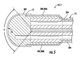
例えば、本開示の図5は、内視鏡72に取付けられた光学要素10の別の態様を示す。図5に示すように、視覚化セクション12の外面16の一部はドーム形状であり、ドーム形状の視覚化セクションの外面の一部分は、内視鏡72の視野A内にある。ドーム形状のために、伝導性材302は、(ドーム全体が覆われている場合は図1~図4と比較して)より滑らかな伝達を有する増加した表面積上に必要とされてもよく、視野A内にのみ適用されてもよい。
For example, FIG. 5 of the present disclosure shows another aspect of the
一般的に、ドーム形状は、臓器を視野から押し出すことができるように、作業空間を増やしてイメージングを改善し得、また視野、光学的明瞭性、対象組織または他の物質に対するレンズの適合性を最適化するために、他の形状を利用し得る。光学要素の形状を適合させるための他の性能に関連する理由としては、光透過、形状間の材料付着、対象ルーメンを含む特定の領域を通るナビゲーションに対する要望を含む。 In general, the dome shape can increase the work space and improve imaging so that the organ can be pushed out of the field of view, as well as the field of view, optical clarity, compatibility of the lens with the target tissue or other material. Other geometries may be utilized for optimization. Other performance-related reasons for adapting the shape of the optics include light transmission, material adhesion between shapes, and the desire for navigation through a particular area, including the lumen of interest.
別の例として、図6および図7は、体腔(body cavity)200の領域と係合する例示的な光学要素10を示す。まず、第1に、光学要素10が体腔200の領域と接触して位置付けられる。次に、医師は、医療器具202(図6)を内視鏡72のシース76の第3ルーメン104に挿入することができる。医療器具は、光学要素において、器具レセプタクル40を通過し、次いで、医療器具202は、バリア・セクション42および光学要素10の外面16(本開示の図7)を貫通する。その後、体腔200の領域上で医療器具を用いて処置することができる。
As another example, FIGS. 6 and 7 show an exemplary
バリア・セクション42は、周囲と器具レセプタクル40との間に(医療器具202が通過する前に)介在する、視覚化セクション12の一部分である。一態様では、伝導性材302を有する医療器具202による直接的な接触を防ぐために、バリア・セクションは、絶縁材310で被覆される。絶縁材310は、例えば、外面16から延在し、また伝導性材302の層と同じかそれ以上の厚さであってもよい。有利には、絶縁材310は、例えば、電気的に通電された伝導性材層にショートを生じさせる金属器具によって、伝導性材302の伝導性破壊を防ぐことができる。または、絶縁材は、医療器具202による損傷に対して、より弾性的で物理的なガードであってもよい。
The
図8Aは、内視鏡72に取付けられた光学要素の別の態様の断面図を示す。この態様は、内視鏡72のルーメン104の1つと、光学要素10の器具レセプタクル40とを通って位置付けられる生検鉗子61を含む。
FIG. 8A shows a cross-sectional view of another aspect of the optical element attached to the
図8Aに示すように、生検鉗子61の挾持部(jaws)は開放されている。図8Bは、体腔200から生検サンプルを採取するために閉じられた生検鉗子の挟持部を有する断面図である。図8Cは、生検サンプルを採取した後に引き取られる生検鉗子の断面図である。
As shown in FIG. 8A, the holding portion (jaws) of the
図8A~図8Cの態様では、光学要素10は、より広い基部が遠位に延在する円錐台形状を有している。この態様では、伝導性材302は比較的フラットであり、比較的フラットな組織表面に容易に適用することができる。また、伝導性材302は、絶縁材310によって取り囲まれた開口部を有する層中にあってもよい。上述したように、これは、生検用鉗子61による伝導性材へのショートまたは損傷を防ぐことができる。また、電極300aおよび300bは、円錐台形状の傾斜した側面の下方へ延在してもよく、また部分的または完全に絶縁されていてもよいし、絶縁されていなくてもよい。
In the embodiments of FIGS. 8A-8C, the
図9Aおよび図9Bは、傾斜した外面16を有する光学要素10の別の態様を示す。例えば、光学要素10は、ボア・スコープ77に載置される光カプラであってもよい。光カプラ10は、第1外側境界515および第2外側境界516を有する視覚化セクション12を有する。第1および第2外側境界515、516は、傾斜してボア・スコープから外側に延在している。カプラ10の外面514はまた、第1セグメント514aおよび第2セグメント514bを有するように傾斜されている。この構成では、伝導性材層302は同様に積層される。
9A and 9B show another aspect of the
図9Bは、2つのプレート88、90間の溶接留め(weld lodged)を検査する図9Aの光学要素10を示す。有利には、電極300は、伝導性層302にエネルギーを供給することができ、伝導性層302は、傾斜したプレート88、90を加熱および/または変更して、例えば、オペレータによって溶接が直接観察される間、溶接は修復される。
FIG. 9B shows the
図10は、第3ルーメン104を介して、補助チャンネルを有する内視鏡に取付けられた光学要素10を示す。液体、空気または他の物質を伝えるための補助チャンネル104の遠位端にノズル943が設けられる。光カプラは、補助液体チャンネル104およびノズル943から液体947を受けることができるスコープの長軸の周辺に延在するチャンバー945を含む。これにより、液体947は、光学要素10における器具レセプタクル40へと入り、通過することができる。このチャンネルは、組織を洗浄するため、または視野からデブリをすすぐため、またはカプラの外面をクリーンにするため、または薬物および他の化学物質、ならびに空気、CO2、アルゴンガスなどの物質および対象とする組織もしくは他の物質に作用させる他の物質を送るための、水や生理食塩水(saline)を含む液体を送ることができる。図10において、伝導性材302には、図1~図4と同様の層が適用される。外部環境の吸引(aspiration)のため、器具が外部に開かれる場合に器具レセプタクル40に正圧を加えるために、開口部は伝導性材302を通って延在し得る。
FIG. 10 shows an
本開示の図11Aは、血液800で覆われた組織に近づく内視鏡72に取付けられた凹状の外面16を有する光学要素10の断面図である。図11Bは、組織200の空洞に押し付けられ、不伝導性の(または不透明の、opaque)液体91を阻止する(または捕捉する、trapping)光学要素10を示す。図11Cは、阻止された不伝導性の液体91を流す(または洗浄する、flush)器具レセプタクル40からの液体を示す。有利には、導入された液体の圧力が、光学要素10によって体腔200に対して加えられる圧力を超えると、液体891は、領域から阻止された不透明液体91を流す。
FIG. 11A of the present disclosure is a cross-sectional view of an
図11Aおよび図11Bにおいて、伝導性材302は、凹型外面16と同様の、凹状の層に適用される。端子300は、凹状伝導性材302の端部と接触するように光学要素10の側面に沿って延在する。
In FIGS. 11A and 11B, the
(デバイスおよび伝導性材の応用)
デバイス11の様々な態様である伝導性材302は、多くのエネルギーの種類を送るために使用され得、また多くの医学的および非医学的用途に用いられ得る。そのようなエネルギーの種類および用途の例は、例示目的のために以下に供され、限定するものとみなされるべきではない。
(Application of devices and conductive materials)
図12に模式的に示すように、伝導性材302は、端子300aおよび300bおよびコネクタ304および電源94へのケーブル96を介して取付けられたレジスタおよび/またはコンデンサである。コネクタ304は、例えば内視鏡のシース76を通り、内視鏡の近位端に取付けられたケーブル96へと延在し得る。これらのコネクタは、電源94に接続し得、例えば電源は、単極エネルギー、双極エネルギー、アルゴンガス・エネルギー、コブレーション・エネルギー、プラズマ・エネルギー、熱エネルギー、マイクロウェーブ・エネルギー、超音波、集束超音波、または治療効果を含む組織もしくは物質を変えるために伝導性コーティングを横切ってもしくは伝導性コーティングを介して伝達され得る複数のエネルギー形態の生成および伝達を含む、他の形態のエネルギーを含む、組織または他の物質の変化のための1またはそれよりも多い形態のエネルギーであり得る。これらは、直流、交流、パルス電流、および他の可変形態のエネルギー送達によって送ることができる。
As schematically shown in FIG. 12, the
端子300および伝導性材302にエネルギーを伝える多くの方法がある。ケーブル96は、端子300、300a、300bを介して伝導性材に電力を送ることができる。ケーブルは、例えば、スコープに隣接しているか、またスコープの外側であるか、またはスコープ72の外側を包み込んでいる(または外側に巻き付いている)ことによって、端子にアクセスすることができる。または、ケーブル96またはコネクタ304は、スコープのワーキング・チャンネル(例えば、第1ルーメン100)を下行するエネルギー送達カテーテルに取り付けることができ、ターミナルとドッキングする。その遠位端において、エネルギー送達カテーテルは、レンズ110のワーキング・チャンネルにおける電気端子に接続され得る。コネクタ304は、内視鏡72のシース76内に埋め込まれ、中空器具レセプタクルコネクタ40に並行して通じ、近接する。コネクタは、フレキシブル回路、1またはそれよりも多いコーティング、ワイヤ、伝導性バネ、電力を受信および送信するための誘導性材、ケーブル、または電源から送達点に向けて電力を送るための他の手法を含んで成り得る。
There are many ways to transfer energy to the
別の態様では、電力ジェネレーターは、例えば、関数ジェネレーター、RF信号ジェネレーター、マイクロウェーブ信号ジェネレーター、ピッチ・ジェネレーター、任意波形ジェネレーター、デジタルパターン・ジェネレーターまたは周波数ジェネレーターなどの信号ジェネレーターを含んで成ることができる。既存の電気外科ジェネレーターは、医学的な使用に必要な基準を満たすという利点と共に使用し得る。これらのジェネレーターは、(アナログまたはデジタルの領域いずれかで)繰り返しまたは非繰り返しの電子信号を生成する電子デバイスに電力を供給し得る。RF信号ジェネレーターの範囲は数kHzから6GHzである。マイクロウェーブ信号ジェネレーターは、1MHz未満から少なくとも20GHzまでの、より広い周波数範囲をカバーすることができる。いくらかのモデルは、直接同軸出力(direct coaxial output)の場合は70GHz、外部導波管ソース・モジュール(external waveguide source modules)の場合は最大数百GHzまで使用できる。また、FMおよびAM信号ジェネレーターを使用し得る。 In another aspect, the power generator can include, for example, a signal generator such as a function generator, an RF signal generator, a microwave signal generator, a pitch generator, an arbitrary waveform generator, a digital pattern generator or a frequency generator. Existing electrosurgery generators can be used with the advantage of meeting the criteria required for medical use. These generators may power electronic devices that generate repetitive or non-repetitive electronic signals (either in the analog or digital domain). The range of the RF signal generator is from a few kHz to 6 GHz. Microwave signal generators can cover a wider frequency range from less than 1 MHz to at least 20 GHz. Some models can be used up to 70 GHz for direct coaxial output and up to hundreds of GHz for external waveguide source modules. FM and AM signal generators may also be used.
これらの異なるジェネレーターなどの利点は、電力の1の形態が他の形態を超える利点がある、対象とする用途のための特定形態の電力を供することである。例えば、組織を切断して凝固させる場合、単極電気は、典型的には双極電力よりも効果的に組織を介して切断および凝固することができる。しかし、単極エネルギーは、意図しない領域への単極エネルギーのアーチング(arching)を避けるために、接地パッド(grounding pad)を使用する必要がある。従って、接地パッドは、組織に影響を及ぼすために、またアーチングおよびその後の電力および単極エネルギーで患者への火傷を防ぐために、単極アプリケーションを使用することができる(設置パッドは、患者を通る電力の回路を完成させる)。 The advantage of these different generators and the like is that one form of power provides a particular form of power for the intended application, which has the advantage over the other. For example, when cutting and coagulating tissue, unipolar electricity can typically cut and coagulate through the tissue more effectively than bipolar power. However, unipolar energy requires the use of a grounding pad to avoid arching the unipolar energy into unintended regions. Thus, the ground pad can be used for unipolar applications to affect tissue and to prevent burns to the patient with arching and subsequent power and unipolar energy (installation pad passes through the patient). Complete the power circuit).
対照的に、双極電力はデバイス自体で回路が完成しているため、エネルギーがデバイスを通過し、また横切って移動し、身体を通ってアーチングすることなく、組織に影響を与える。このアプローチでは、双極電力は、組織の対象とする治療を含む病変、シーリング容器および他の用途を作り出すために非常に効果的であり得る。しかし、双極電力の含まれた側面のために、外科用ナイフの代替物として組織を切断して凝固させることは、それほど効果的でない傾向がある。同様に、マイクロウェーブ・エネルギーは、その独特な組織効果に起因して、組織のアブレーションの特定タイプに使用され得、双極エネルギーは、他のタイプの切除に使用され得る。周波数が、例えば神経束のような特定の副要素を刺激(excite)しないので、FMエネルギーのような他の形態のエネルギーが使用され得る。 In contrast, bipolar power has its own circuit completed by the device itself, so energy travels across and across the device, affecting tissues without arching through the body. In this approach, bipolar power can be very effective in creating lesions, sealing vessels and other uses, including treatments of interest in tissues. However, due to the bipolar power-containing aspects, cutting and coagulating tissue as an alternative to surgical knives tends to be less effective. Similarly, microwave energy can be used for certain types of tissue ablation due to its unique tissue effect, and bipolar energy can be used for other types of excision. Other forms of energy, such as FM energy, can be used because the frequency does not excite certain subelements, such as nerve fascicles.
コアブレーション(coablation)・ジェネレーターは、高周波エネルギーを用いて軟組織を外科的に解離させる非熱駆動プロセスにおいて使用することができ、生理食塩水などの伝導性媒体における電解質を励起して、正確に集束したプラズマ場を形成する。プラズマ場におけるエネルギー付与された粒子またはイオンは、比較的低い温度(すなわち、典型的には40℃~70℃)で軟組織内の有機分子結合を破壊または解離するのに十分なエネルギーを有することができる。これにより、周囲の組織への損傷を最小限にして、コブレーション・デバイスが対象の組織を容積分析で除去することが可能になる。コブレーションは、止血および組織収縮能も供することができる。送られる電力の量は、場の強度によって決定され、局所環境条件に基づいて調節することができる。 Coablation generators can be used in non-thermally driven processes that use high frequency energy to surgically dissociate soft tissues, exciting and accurately focusing electrolytes in conductive media such as saline. Form a plasma field. The energized particles or ions in the plasma field may have sufficient energy to break or dissociate the organic molecular bonds in the soft tissue at relatively low temperatures (ie, typically 40 ° C to 70 ° C). can. This allows the cobulation device to remove the tissue of interest by volumetric analysis with minimal damage to surrounding tissue. Coblation can also provide hemostasis and tissue contractility. The amount of power sent is determined by the strength of the field and can be adjusted based on local environmental conditions.
コブレーションは、典型的には90℃までの温度範囲で使用することができる。 Coblation can typically be used in the temperature range up to 90 ° C.
超音波ジェネレーターは、約20キロヘルツ(20,000ヘルツ)より大きい周波数を有する音波を発生することができる。超音波は、伝導性材302によって組織200に伝導し得る。超音波は、身体組織、特に靭帯、腱および筋膜、または他の物質によって吸収され得る。
The ultrasonic generator can generate sound waves with frequencies greater than about 20 kilohertz (20,000 hertz). The ultrasonic waves can be conducted to the
超音波デバイスは、典型的には20KHzから数GHzまでの周波数で動作することができる。使用される治療上の超音波周波数は、典型的には0.7~3.3MHzである。超音波エネルギーまたはTENSエネルギーは、治療領域において血流を増加させることによって、治癒プロセスを加速させることができ、また治療領域における筋肉の腱および/または靭帯を静かにマッサージすることによって、腫脹および浮腫の収縮による痛みを軽減させることができる。 Ultrasonic devices can typically operate at frequencies from 20 KHz to several GHz. The therapeutic ultrasonic frequency used is typically 0.7-3.3 MHz. Ultrasound or TENS energy can accelerate the healing process by increasing blood flow in the therapeutic area, and swelling and edema by gently massaging the tendons and / or ligaments of the muscles in the therapeutic area. The pain caused by the contraction of the swelling can be reduced.
超音波はまた、非侵襲的または侵襲的に腫瘍または他の組織をアブレートし得る。これは、高強度集束超音波(HIFU)として知られている技術(集束超音波手術(FUS手術)とも呼ばれる)を用いて達成することができる。この手順では、医学的診断超音波(250~2000kHz)より一般的に低い周波数を使用する。超音波が治療のために使用され得る他の一般的な状況として、例えば、靭帯捻挫、筋肉痛、腱炎、関節炎症、足底筋膜炎、中足痛、面刺激、インピンジメント症候群、滑液包炎、関節リウマチ、変形性関節症および瘢痕組織接着などの例が含まれる。 Ultrasound can also ablate tumors or other tissues non-invasively or invasively. This can be achieved using a technique known as High Intensity Focused Ultrasound (HIFU) (also referred to as Focused Ultrasound Surgery (FUS Surgery)). This procedure uses frequencies generally lower than medical diagnostic ultrasound (250-2000 kHz). Other common situations in which ultrasound can be used for treatment include, for example, ligament contusion, muscle pain, tendinitis, joint inflammation, sole myelitis, midfoot pain, surface irritation, impingement syndrome, slippage. Examples include bursitis, rheumatoid arthritis, osteoarthritis and scar tissue adhesion.
デバイス11はまた、医師が、特に、組織の焼灼、血管シーリング、組織切開および組織再切開、組織形成、組織切除および組織凝固、組織アブレーションおよび器具加熱を、施術者が観察できる正確な位置で全て行うことを可能にする。これは、少なくとも部分的に、ブラインドにおける内視鏡手術の態様を実行する問題を解決するものである。それはまた、組織もしくは物質にエネルギーを加えさせるための、または組織や他の物質を光の向きを変えるための、または視覚化を維持しながら他の操作に従事させるための、あるデバイスを別のデバイスと交換する必要性を排除することもできる。
The
より具体的な医療用途には、特に、外傷症例において組織に作用するエネルギーの適用、関節鏡手術、脊椎手術、神経外科手術、肩関節手術、肺腫瘍アブレーション、膀胱癌患者の癌組織のアブレーション、女性の健康課題(例えば、子宮内膜症)のための子宮組織の焼灼またはアブレーションを含む。これらの用途(および本明細書中に列挙される他の用途)において、デバイスは、組織に接触し、次いで組織を焼灼し、組織をアブレートし、または成形することに使用され(例えば、肩の処置において、コブレーション・エネルギーで行われる)、医師が、例えば、光学的に透明なレンズおよびコーティングを介して、リアルタイムで組織に起こる変化を観察することができることによって、比類のないパフォーマンス特性を作り出す。 More specific medical applications include application of energy acting on tissues, especially in traumatic cases, arthroscopic surgery, spinal surgery, neurosurgery, shoulder joint surgery, lung tumor ablation, ablation of cancerous tissue in bladder cancer patients, Includes ablation or ablation of uterine tissue for women's health issues (eg, endometriosis). In these uses (and other uses listed herein), the device is used to contact the tissue and then ablate the tissue, ablate or shape the tissue (eg, shoulder). In the procedure, it is done with coblation energy), creating unparalleled performance characteristics by allowing the physician to observe the changes that occur in the tissue in real time, for example, through an optically transparent lens and coating. ..
このデバイスは、腹腔鏡、ボア・スコープ、ビデオ・スコープまたは他の光学キャプチャ技術を含む用途において、フォギングを防止するために、光学的に透明なレンズを加熱して使用することもできる。 The device can also be used by heating an optically transparent lens to prevent fogging in applications including laparoscopes, borescopes, videoscopes or other optical capture techniques.
医療用途をさらに詳しく説明するために、ジアテルミー用途におけるデバイスの使用は、短波無線周波数(1~100MHzの範囲)またはマイクロウェーブ・エネルギー(典型的には915MHzまたは2.45GHz)を使用して達成されるかどうかにかかわらず、有用な領域である。手術で使用されるジアテルミーは、少なくとも2つのタイプを含んで成ることができる。単極エネルギーは、治療すべき組織の近くの一方の電極から、体内の他の位置に固定された電極に電流が流れる場所である。通常、このタイプの電極は、身体の特定の場所に(例えば、臀部または脚の周囲と接触して)位置付けられる。これとは別に、双極エネルギーを使用することができ、両方の電極がデバイス上に閉じた電気回路を形成する近位端(この場合、光学要素10上の2つの別個の伝導性材部分302)に近接して載置され、治療すべき組織を通って、または組織上だけを電流が通る。双極電気手術の利点は、身体の他の組織を通る電流の流れを防止し、また電極に接触または近接している組織にのみに焦点を当てられることである。これは、例えば、マイクロ手術、腹腔鏡手術、心臓手術および他の処置(心臓ペースメーカーを有する患者ならびに他のデバイスおよび他の形態のエネルギーでの使用に適さない状態を含む処置)において有用である。
To further illustrate medical applications, the use of devices in diathermy applications has been achieved using short wave radio frequencies (range 1-100 MHz) or microwave energy (typically 915 MHz or 2.45 GHz). It is a useful area, whether or not. Diathermy used in surgery can consist of at least two types. Unipolar energy is where current flows from one electrode near the tissue to be treated to an electrode fixed at another location in the body. Usually, this type of electrode is positioned at a specific location on the body (eg, in contact with the buttocks or around the legs). Separately, bipolar energy can be used and both electrodes form a closed electrical circuit on the device at the proximal end (in this case, two separate
電気焼灼は、電流から熱伝導を利用して組織を修正するプロセスである。この手順は、小さな血管からの出血を止めるために(より大きな血管を結紮することができる)、または柔らかい組織を通る切断からの出血を止めるために使用される。高周波交流は、単極(unipolar)方式または双極方式において電気焼灼に使用される。連続波形(組織を切断する)または間欠的なタイプ(組織を凝固させる)であり得る。単極タイプでは、電気火傷を防止するために、回路の出口点は表面積が大きい(例えば、臀部)一方で、凝固/切断される組織は小さな電極と接触する。発生する熱は、接触面積の大きさ、電流のパワー設定または周波数、印加時間、波形に依存する。組織を切断する際に使用される周波数が凝固モード(coagulation mode)よりも高く設定されるため、(一般的に)一定の波形は、間欠的な波形よりも大きな熱を発生させる。双極電気焼灼は、組織または他の物質に影響を与えるために2点間の回路を確立する。 Electrocautery is the process of modifying tissue using heat conduction from an electric current. This procedure is used to stop bleeding from small blood vessels (which can ligate larger blood vessels) or to stop bleeding from cuts through soft tissue. High frequency alternating current is used for electrocautery in unipolar or bipolar systems. It can be a continuous waveform (cutting tissue) or an intermittent type (coagulating tissue). In the unipolar type, the exit point of the circuit has a large surface area (eg, buttocks) to prevent electrical burns, while the coagulated / cut tissue contacts the small electrodes. The heat generated depends on the size of the contact area, the power setting or frequency of the current, the application time, and the waveform. A constant waveform (generally) produces more heat than an intermittent waveform because the frequency used to cut the tissue is set higher than the coagulation mode. Bipolar electrocautery establishes a circuit between two points to affect tissue or other material.
別のオプションとして、伝導性層302およびデバイス11は、50℃~100℃の範囲、またはさらには50℃~70℃の範囲、または推奨される場合はより低い温度で、用途に適した電力範囲を適用して、熱焼灼に使用することができる。有利なことに、デバイスを通して適用されるエネルギーの形態として視覚化する能力は、電力の正確な送達を可能とし、エネルギーのレベルおよび結果としての温度を変化させること、特定の用途に適するパワー設定を使用すること、範囲を広げるためにより長い期間にわたってエネルギーを印加すること、複数の効果を得るために複数の電極に沿ってエネルギーを印加すること、ならびに組織またはその他の物質が十分に変換されたことをより確定させてプロセスを停止させる能力を含む(この利点はもちろん、デバイス11の他の適用にも当てはまり、エネルギー・アプリケーションのリアルタイムの視覚的な監視により、より正確な適用が可能になる)。
As another option, the
光学要素10は、非医療用途においても有益であり得る。光学要素の態様は、ボア・スコープの遠位端(対物レンズ)に取付けることができ、またはマイクロもしくは常套的なビデオカメラ、検査スコープ、もしくはスチルカメラ、あるいは液体、デブリおよび/もしくは血液の視覚化ならびにエネルギーの送達を改善することから有益となる他の視覚化デバイスに取付けることができる。これにより、石油製品、下水道、食品、塗料など、液体が不透明である場合を含む、配管、保持タンク、コンテナ、油圧ラインおよび視覚化が損なわれる可能性のあるその他の状況の改善された視野および修復能力の可能性が供される。バイオ医薬品製造、医薬品およびその他の用途は、パイプまたは容器(例えば、油槽)を空にするか、または検査するためにラインを開ける必要がなくなり、この革新から恩恵を受けるであろう。
The
光学要素のサイズまたは柔軟性は、特定の用途(例えば、広い領域を調べるときに大量の液体を移動させること)に合わせてスケールする(または尺度を設計する、scale)ことができる。光学要素の形状は、一般的に、特定の作業のためにフラット、凸状(曲率のレベルが異なる)、角度のある(angled)、傾斜(sloped)、階段状または特定の目的のための他の形状とすることができる。例えば、光学要素は、継ぎ目を検査するためにタンクのコーナーにおける不透明液体を移動させるように、正方形または角形の形状にし得る。パイプ、ライン、チューブ、トンネルおよびその他の通路において、継手、溶接部、腐食のための継ぎ目、パイプ、フレキシブルおよび非フレキシブルな管状部材、または亀裂、表面収差、および検査および修復における他の点の点検(examination)を行うことができる。 The size or flexibility of the optics can be scaled (or scaled, scaled) to a particular application (eg, moving a large amount of liquid when examining a large area). The shape of the optics is generally flat, convex (different levels of curvature), angled, sloped, stepped or other for a particular purpose for a particular task. Can be in the shape of. For example, the optics can be in the shape of a square or square to move the opaque liquid in the corners of the tank to inspect the seams. Inspection of fittings, welds, seams for corrosion, pipes, flexible and non-flexible tubular members, or cracks, surface aberrations, and other points in inspection and repair in pipes, lines, tubes, tunnels and other passages. (Examination) can be performed.
光学要素は、遠隔した位置を観察するために、画像キャプチャ要素及びロボット媒体(vehicle)又はロボット・アームと共に使用することができる。ワーキング・チャンネルを有する光学部品は、ネジ、接着剤パッチ、接着剤、化学薬品、溶接、はんだ付け、および他の修理および修正の用途を使用して修理を行うために、デバイスが光学要素を通過することを可能にする。態様では、光学要素は、光学要素によって移される液体の酸性、アルカリ性、高熱、または粘度に耐える材料から形成することができる。態様では、デバイスは、使い捨てのデバイスまたは再使用可能なデバイスであってもよい。 Optical elements can be used with image capture elements and robotic vehicles or robot arms to observe remote locations. Optical components with working channels allow devices to pass through optical elements for repairs using screws, adhesive patches, adhesives, chemicals, welding, soldering, and other repair and repair applications. Allows you to do. In aspects, the optics can be formed from a material that can withstand the acidity, alkalinity, heat, or viscosity of the liquid transferred by the optics. In aspects, the device may be a disposable device or a reusable device.
有利なことに、デバイス11の態様は、これらの様々な非医療用途において、伝導性材302を介してエネルギーを印加する能力を供する。観察される対象に供されるエネルギーは、光学要素10によって観察される対象を加熱し、変化させ、またはそうでなければ影響を与え得る。
Advantageously, the embodiment of the
(伝導性材の組成)
伝導性材302は、様々な組成を有し得、様々な方法で光学要素10に適用され得る。そのような組成および用途の例は、例示の目的のために以下に供され、限定的であるとみなされるべきではない。医療用途では、伝導性材302は、例えば、ガンマ線照射、エチレンオキシド、蒸気、または他の形態の滅菌による、滅菌に耐え得ることが好ましい。
(Composition of conductive material)
The
電気的な伝導性/応答性コーティングは、1またはそれよりも多い電極を生成するために複数の構成で適用することができる。この電極は、光学的に透明とすることができ、また組織または他の物質に対する意図された効果に応じて、半ミクロン以下の厚さおよびより厚い厚さを含む様々な厚さを有することができる。 Electrically conductive / responsive coatings can be applied in multiple configurations to produce one or more electrodes. The electrode can be optically transparent and can have a variety of thicknesses, including less than half a micron and thicker, depending on the intended effect on the tissue or other material. can.
伝導性材は、少なくとも部分的に透明とすることができ、例えば、(2つの例示として)酸化チタン(TiO2)およびアルミニウムをドープした酸化亜鉛(AZO)を含む透明伝導性酸化物(TCO)として知られる材料の一般分類のあらゆる部材を含んで成ることができる。また、例えば銀ナノ粒子および金ナノ粒子などの視覚化を可能にする方法で適用される他の伝導性材、ならびにエネルギーの伝導および視覚化を可能にする方法で適用される他の伝導性材の用途を含むこともできる。 The conductive material can be at least partially transparent, eg, a transparent conductive oxide (TCO) containing titanium oxide (TiO 2 ) and aluminum-doped zinc oxide (AZO) (as two examples). It can consist of any member of the general classification of materials known as. Also, other conductive materials applied in a manner that allows visualization, such as silver nanoparticles and gold nanoparticles, as well as other conductive materials that are applied in a manner that allows energy conduction and visualization. Can also include uses for.
視覚化材の光学回折率は、用途、所望の光透過レベル、全体の光学性能および他の要因に応じて、1.3~2.3の範囲の屈折率を有する材料を含む。透明伝導性酸化物は、380nm~750nmの可視範囲よりも短い波長に対応するエネルギーを有するバンドギャップを有する透明材を含んで成ることができる。TCOの膜(またはフィルム、film)は、例えばその表面上の点を横切って変化する伝導性を有することができる。一態様では、膜は、ポーラス、ピンホール、および/または欠陥を有さないか、または実質的に有さない。別の態様では、層におけるポーラス、ピンホールおよび/または欠陥の数およびサイズは、デバイスにおいて、層の性能に悪影響を与えない。膜の厚さは、1未満~約3500nmの範囲とすることができる。態様では、異なる製造方法および意図された用途に応じて、例えば、約10、20、30、40、50、60、70、80、100、200、300、400、500、600、700、800、900、1000、1300、および1500nmの厚さなどの異なる厚さとすることができる。 The optical diffraction index of the visualization material includes materials having a refractive index in the range of 1.3 to 2.3, depending on the application, the desired light transmission level, the overall optical performance and other factors. The transparent conductive oxide can comprise a transparent material having a bandgap with energies corresponding to wavelengths shorter than the visible range of 380 nm to 750 nm. A TCO film (or film) can have varying conductivity across points on its surface, for example. In one aspect, the membrane is free or substantially free of porous, pinhole, and / or defects. In another aspect, the number and size of porouss, pinholes and / or defects in the layer do not adversely affect the performance of the layer in the device. The film thickness can range from less than 1 to about 3500 nm. In aspects, for example, about 10, 20, 30, 40, 50, 60, 70, 80, 100, 200, 300, 400, 500, 600, 700, 800, depending on different manufacturing methods and intended uses. It can have different thicknesses such as 900, 1000, 1300, and 1500 nm.
透明導電膜は、インジウムスズ酸化物、AlまたはGaをドープした酸化亜鉛、TaまたはNbをドープした酸化チタン、Fをドープした酸化スズ、およびそれらの混合物とすることができる。酸化物層は、超薄金属層を直接酸化することによって、または酸化物を蒸着させることによって形成することができる。TCO材は、膜特性(他の特性の中でも、例えば、透過率および導電率を含む特性)に影響を及ぼすために、多結晶、結晶または非晶質の微細構造を有することができる。 The transparent conductive film can be indium tin oxide, zinc oxide doped with Al or Ga, titanium oxide doped with Ta or Nb, tin oxide doped with F, and a mixture thereof. The oxide layer can be formed by directly oxidizing the ultrathin metal layer or by depositing an oxide. The TCO material can have a polycrystalline, crystalline or amorphous microstructure to affect the membrane properties (among other properties, including, for example, transmittance and conductivity).
透明伝導性材として生体適合性のTCOを使用することもできる。例えばこれらの材料は、酸化アルミニウム(Al2O3)、ハイドロキシアパタイト(HA)、二酸化ケイ素(SiO2)チタンカーバイド(TiC)、窒化チタン(TiN)、二酸化チタン(TiO2)、二酸化ジルコニウム(ZrO2)を含む。これらの材料は、例えば、アルミニウム(Al)、銅(Cu)、銀(Ag)、ガリウム(Ga)、マグネシウム(Mg)、カドミウム(Cd)、インジウム(In)、スズ(Sn)、スカンジウム(Sc)、イットリウム(Y)、コバルト(Co)、マンガン(Mn)、クロム(Cr)、およびホウ素(B)などの他の金属を有するnドープであり得る。pドーピングは、特に窒素(N)およびリン(P)を用いて達成することができる。 Biocompatible TCO can also be used as the transparent conductive material. For example, these materials include aluminum oxide (Al 2 O 3 ), hydroxyapatite (HA), silicon dioxide (SiO 2 ) titanium carbide (TiC), titanium nitride (TiN), titanium dioxide (TIO 2 ), and zirconium dioxide (ZrO). 2 ) is included. These materials include, for example, aluminum (Al), copper (Cu), silver (Ag), gallium (Ga), magnesium (Mg), cadmium (Cd), indium (In), tin (Sn), scandium (Sc). ), Yttrium (Y), cobalt (Co), manganese (Mn), chromium (Cr), and n-doped with other metals such as boron (B). P-doping can be achieved specifically with nitrogen (N) and phosphorus (P).
TiO2は、生体適合性材として機能することができ、室温から数百℃の温度範囲で基材を被覆する可能性を供する。TiO2は、初期粒子サイズ、初期相、ドーパント濃度、反応雰囲気およびアニーリング温度に依存し得る複数の異なる多様な形の相を有する。TiO2膜は、ゾルゲル、溶射、および物理蒸着を含む多くの方法によって一般的に合成される。 TiO 2 can function as a biocompatible material and offers the possibility of coating a substrate in a temperature range of room temperature to several hundred degrees Celsius. TiO 2 has a number of different and diverse forms of phase that can depend on the initial particle size, initial phase, dopant concentration, reaction atmosphere and annealing temperature. TiO 2 films are commonly synthesized by many methods including sol-gel, thermal spraying, and physical deposition.
透明伝導性の、アルミニウムドープ酸化亜鉛薄膜(AlxZnyOz、ZnO:Al)は少量(典型的には5重量%未満)のアルミニウムを含む。下にある基板は、材料の膜の成長した構造および光電子特性に影響を及ぼし得る。基板が同一であっても、層の厚さ(蒸着時間、基板上の位置)自体が、蒸着された薄膜の物理的な数値に影響を及ぼす。 The transparent conductive aluminum-doped zinc oxide thin film (Al x Zn yOz , ZnO : Al) contains a small amount (typically less than 5% by weight) of aluminum. The underlying substrate can affect the grown structure and photoelectronic properties of the material's film. Even if the substrates are the same, the layer thickness (deposited time, position on the substrate) itself affects the physical value of the vapor-deposited thin film.
成長した薄膜からの物理的な数値の変化は、(温度または圧力とする)プロセス・パラメータを変化させることによって、または(酸素または水素とする)プロセスガスへの添加によって達成することもできる。一般的に、酸化亜鉛はアルミニウムでnドープされている。別に、nドーピングは、例えば、銅(Cu)、銀(Ag)、ガリウム(Ga)、マグネシウム(Mg)、カドミウム(Cd)、インジウム(In)、スズ(Sn)、スカンジウム(Sc)、イットリウム(Y)、コバルト(Co)、マンガン(Mn)、クロム(Cr)、およびホウ素(B)などの金属と共に実施できる。ZnOのpドーピングは、窒素(N)およびリン(P)を用いて達成することができる。 Changes in physical values from the grown thin film can also be achieved by varying process parameters (as temperature or pressure) or by addition to the process gas (as oxygen or hydrogen). Generally, zinc oxide is n-doped with aluminum. Separately, n-doping includes, for example, copper (Cu), silver (Ag), gallium (Ga), magnesium (Mg), cadmium (Cd), indium (In), tin (Sn), scandium (Sc), yttrium ( It can be carried out with metals such as Y), cobalt (Co), manganese (Mn), chromium (Cr), and boron (B). ZnO p-doping can be achieved with nitrogen (N) and phosphorus (P).
さらに、TCOにおいて、サブ波長の金属ナノ構造を組み込むことによって、TCOが透明になる波長への変化をもたらすことができる。埋め込まれた粒子物品(embedded particles articles)はまた、所望の波長で吸収および散乱を制御するために使用され得る。材料の他の光学効果(吸収、散乱、光の閉じ込めまたは分解、ろ過、光誘起加熱などを含む効果)にも影響を与えることができる。粒子の形態(サイズ、形状、密度、均一性、適合性、分離、配置およびランダムまたは周期的な分布を含む形態)により、これらの効果を設計することができる。 Furthermore, by incorporating sub-wavelength metal nanostructures in TCO, it is possible to bring about a change to a wavelength at which TCO becomes transparent. Embedded particles articles can also be used to control absorption and scattering at the desired wavelength. Other optical effects of the material, including absorption, scattering, light confinement or decomposition, filtration, photoinduced heating, etc., can also be affected. These effects can be designed by the morphology of the particles, including size, shape, density, uniformity, compatibility, separation, placement and random or periodic distribution.
本発明の電極の基板は、本発明の透明電極構造が適用される、あらゆる適切な材料から成ることができる。これは、別の伝導性材または誘電材を含むことができる。1つの例示的な実施例では、光学要素10は基板として機能する。他の基板には、特に、ガラス、半導体、無機結晶、硬質またはフレキシブルなプラスチック材が含まれる。例示的な実施例として、特に、シリカ(SiO2)、ホウケイ酸塩(BK7)、ケイ素(Si)、ニオブ酸リチウム(LiNbO3)、ポリエチレンナフタレート(PEN)、ポリエチレンテレフタレート(PET)である。
The substrate of the electrode of the present invention can be made of any suitable material to which the transparent electrode structure of the present invention is applied. It can include another conductive or dielectric material. In one exemplary embodiment, the
有機材は、伝導性材としても機能することができる。これらには、ポリ(3、4-エチレンジオキシチオフェン)およびその誘導体などのポリマーのネットワークとともに、赤外光に対して高度に透明に製造できる、カーボンナノチューブ・ネットワークおよびグラフェンが含まれる。 The organic material can also function as a conductive material. These include polymers such as poly (3,4-ethylenedioxythiophene) and derivatives thereof, as well as carbon nanotube networks and graphene, which can be made highly transparent to infrared light.
ポリマーは、伝導性材としても機能することができる。例えば、ポリアセチレン、ポリアニリン、ポリピロールまたはポリチオフェンの誘導体などの伝導性ポリマーである。例としては、ポリ(3、4-エチレンジオキシチオフェン)(PEDOT)、およびPEDOT:ポリ(スチレンスルホネート)PSSである。さらに、ヨウ素をドープしたポリ(4、4-ジオクチルシクロペンタジチオフェン)または2、3-ジクロロ-5、6-ジシアノ-1、4-ベンゾキノン(DDQ)を使用することができる。n型またはp型ドーパントを有する他のポリマーを使用することもできる。 The polymer can also function as a conductive material. For example, conductive polymers such as polyacetylene, polyaniline, polypyrrole or polythiophene derivatives. Examples are poly (3,4-ethylenedioxythiophene) (PEDOT), and PEDOT: poly (styrene sulfonate) PSS. In addition, iodine-doped poly (4,4-dioctylcyclopentadithiophene) or 2,3-dichloro-5,6-dicyano-1,4-benzoquinone (DDQ) can be used. Other polymers with n-type or p-type dopants can also be used.
伝導性材の膜は、金属有機化学蒸着(MOCVD)、金属有機分子ビーム蒸着(MOMBD)、噴霧熱分解(spray pyrolysis)、およびパルスレーザ蒸着、ディップ・コーティング、ペインティング、接着または特定の用途のために伝導性材を所与の基板に適切に接着させるのに適する他の用途を含む、様々な蒸着方法を介して基板上に蒸着させることができる。TCOの製造技術は、膜のマグネトロン・スパッタリング、ゾルゲル技術、電着、気相蒸着、マグネトロンDCスパッタリング、マグネトロンRFスパッタリング、またはスパッタ蒸着法、超音波送達および溶接の両方の組合せを含む。加えて、熱プラズマ、(低圧(LP)、金属有機(MO)、プラズマ増強(PE))化学蒸着(CVD)、電子ビーム蒸発、パルスレーザ蒸着および原子層蒸着(ALD)を用いる高品質蒸着方法が、特に適用することができる。 Conductive material films can be used for metal-organic chemical deposition (MOCVD), metal-organic molecular beam deposition (MOMBD), spray pyrolysis, and pulsed laser deposition, dip coating, painting, bonding or specific applications. It can be deposited onto a substrate via a variety of deposition methods, including other uses suitable for properly adhering the conductive material to a given substrate. TCO manufacturing techniques include film magnetron sputtering, solgel techniques, electrodeposition, gas phase deposition, magnetron DC sputtering, magnetron RF sputtering, or a combination of sputter deposition methods, ultrasonic delivery and welding. In addition, high quality vapor deposition methods using thermal plasma, (low pressure (LP), metal organic (MO), plasma enhanced (PE)) chemical vapor deposition (CVD), electron beam evaporation, pulsed laser deposition and atomic layer deposition (ALD). However, it is particularly applicable.
ALDなどの、わずか数ナノメートルの厚さの薄膜はフレキシブルであり、従って、人体内部の内部または非医学的な所与の検査部位の内部の有害な粒子の、割れおよび形成および広がりおよび拡散が起こりにくい。また、低および高タンパク質を結合する親和性コーティングは、ALDによって蒸着させることができる。それらは、診断および調製分野において、ならびに細菌増殖に耐性のある表面コーティングに特に有用である。 Thin films as thick as only a few nanometers, such as ALDs, are flexible, thus cracking and forming and spreading and diffusing harmful particles inside the human body or inside a given non-medical examination site. It is unlikely to occur. Also, affinity coatings that bind low and high proteins can be deposited by ALD. They are particularly useful in the field of diagnosis and preparation, as well as surface coatings that are resistant to bacterial growth.
改善された伝導性材の特性を得るために、前後の蒸着処理(例えば、酸素プラズマ処理および熱処理)を組合せることができる。酸素プラズマは、基板または伝導性材が高温によって影響を受ける場合に好ましい。伝導性材膜は、プロセス・パラメータの変動に応じて、広範囲の材料特性を有することができる。例えば、プロセス・パラメータを変化させることにより、広範囲の、伝導性特性および膜の形態を得ることができる。 Pre- and post-deposition treatments (eg, oxygen plasma treatment and heat treatment) can be combined to obtain improved conductive material properties. Oxygen plasma is preferred when the substrate or conductive material is affected by high temperatures. Conductive material membranes can have a wide range of material properties in response to variations in process parameters. For example, by varying the process parameters, a wide range of conductive properties and membrane morphology can be obtained.
本明細書で使用する「コネクタ(connector)」という用語は、伝導性コーティングへの、電気的な、または他のエネルギーの伝達を可能にするあらゆる構造を意味すると広く解釈されるべきである。「コネクタ(connector)」という用語は、永久的な接続(はんだ、接着剤、撚り線、伝導性コーティングを有する伝導路)または交換可能な接続(プラグおよびハーネス・アッセンブリのような接続)、または電源から伝導性コーティングへとエネルギーを送る他の方法を指すことができる。コーティングまでの繋がるすべての方法は、物理的な接続である必要はない。例えば、電磁場を介して、例えば、インダクタンスによって、接続することができる。用語「コネクタ(connector)」はまた、接続を可能にし、仲介し、強化し、あるいは他の方法で容易にする、構造および/または機能を含み得る。特定のタイプのコネクタは、例えば電源との電気的な接続を供されるか、または電源との電気的な接続が可能な伝導性材の領域であり得る端子である。端子は、例えば、表面上に蒸着され、またエネルギー供給カテーテル上のワイヤの端部と接触するように成形された伝導性金属層であり得る。 The term "connector" as used herein should be broadly construed to mean any structure that allows the transfer of electrical or other energy to a conductive coating. The term "connector" refers to permanent connections (solders, adhesives, strands, conduction paths with conductive coatings) or replaceable connections (connections such as plugs and harness assemblies), or power supplies. Can refer to other ways of sending energy from to a conductive coating. Not all ways to connect to the coating need to be physical connections. For example, they can be connected via an electromagnetic field, for example, by inductance. The term "connector" may also include structures and / or functions that enable, mediate, enhance, or otherwise facilitate connections. A particular type of connector is a terminal that may be, for example, an area of conductive material that is provided with an electrical connection to a power source or is capable of an electrical connection to a power source. The terminal can be, for example, a conductive metal layer deposited on the surface and shaped to contact the end of the wire on the energy supply catheter.
「コネクタ領域(connector area)」は、コネクタを取付け、載置し、被覆し、接着し、固定し、粘着し、層状にし、重ねることができる領域、またはそうでなければ伝導性コーティングにエネルギーを伝えることができる領域である。 A "connector area" is an area where a connector can be attached, placed, coated, glued, fixed, adhered, layered, layered, or otherwise energized to a conductive coating. It is an area that can be communicated.
システム、デバイスおよび方法についての多くの態様が説明されている。それにもかかわらず、本開示の主旨および範囲から逸脱することなく、様々な変更がなされ得ることを理解されたい。従って、他の態様も、添付の特許請求の範囲内にある。 Many aspects of the system, device and method are described. Nevertheless, it should be understood that various changes may be made without departing from the gist and scope of this disclosure. Therefore, other aspects are also within the scope of the attached claims.
Claims (12)
視覚化セクションを遠位端に備えると共に、前記内視鏡に取り付けるための取付けセクションを近位端に備える光学カプラ、
前記光学カプラの少なくとも一部分に設けられ、且つ少なくとも部分的に透明である伝導性材から構成されるコーティング、
前記伝導性材にエネルギーを供することができる少なくとも1つのコネクタ、および
前記光学カプラ内にあり、器具または液体を通過させるワーキング・チャンネル
を有して成る、デバイス。 A device used with an endoscope,
An optical coupler with a visualization section at the distal end and a mounting section at the proximal end for attachment to the endoscope.
A coating made of a conductive material provided on at least a portion of the optical coupler and at least partially transparent .
A device comprising at least one connector capable of supplying energy to the conductive material and a working channel within the optical coupler that allows an instrument or liquid to pass through.
観察端部を有する画像キャプチャ・デバイス、
観察端部を支持するポジショニング・アッセンブリ、
観察端部上に設けられ、該観察端部にわたってエネルギーが伝達されるように配置および構成される伝導面、
前記ポジショニング・アッセンブリ内にあり、器具または液体を通過させるワーキング・チャンネル、ならびに
エネルギーを前記伝導面に供給するように構成される電源接続部
を有して成る、アッセンブリ。 It ’s an assembly,
Image capture device with observation edge,
Positioning assembly to support the observation edge,
A conduction surface provided on the observation end and arranged and configured to transfer energy over the observation end.
An assembly that is within the positioning assembly and has a working channel through which an instrument or liquid passes, as well as a power connection configured to supply energy to the conduction surface.
Priority Applications (2)
| Application Number | Priority Date | Filing Date | Title |
|---|---|---|---|
| JP2021199322A JP7315254B2 (en) | 2015-06-02 | 2021-12-08 | conductive optical element |
| JP2023111370A JP2023118922A (en) | 2015-06-02 | 2023-07-06 | conductive optical element |
Applications Claiming Priority (3)
| Application Number | Priority Date | Filing Date | Title |
|---|---|---|---|
| US14/728,812 | 2015-06-02 | ||
| US14/728,812 US10548467B2 (en) | 2015-06-02 | 2015-06-02 | Conductive optical element |
| PCT/US2016/035566 WO2016196826A1 (en) | 2015-06-02 | 2016-06-02 | Conductive optical element |
Related Child Applications (1)
| Application Number | Title | Priority Date | Filing Date |
|---|---|---|---|
| JP2021199322A Division JP7315254B2 (en) | 2015-06-02 | 2021-12-08 | conductive optical element |
Publications (3)
| Publication Number | Publication Date |
|---|---|
| JP2018524131A JP2018524131A (en) | 2018-08-30 |
| JP2018524131A5 JP2018524131A5 (en) | 2019-07-04 |
| JP6995368B2 true JP6995368B2 (en) | 2022-01-14 |
Family
ID=57442283
Family Applications (3)
| Application Number | Title | Priority Date | Filing Date |
|---|---|---|---|
| JP2018515186A Active JP6995368B2 (en) | 2015-06-02 | 2016-06-02 | Conductive optics |
| JP2021199322A Active JP7315254B2 (en) | 2015-06-02 | 2021-12-08 | conductive optical element |
| JP2023111370A Pending JP2023118922A (en) | 2015-06-02 | 2023-07-06 | conductive optical element |
Family Applications After (2)
| Application Number | Title | Priority Date | Filing Date |
|---|---|---|---|
| JP2021199322A Active JP7315254B2 (en) | 2015-06-02 | 2021-12-08 | conductive optical element |
| JP2023111370A Pending JP2023118922A (en) | 2015-06-02 | 2023-07-06 | conductive optical element |
Country Status (10)
| Country | Link |
|---|---|
| US (3) | US10548467B2 (en) |
| EP (1) | EP3302225A4 (en) |
| JP (3) | JP6995368B2 (en) |
| KR (1) | KR20180019618A (en) |
| CN (2) | CN108135462B (en) |
| AU (4) | AU2016270959B2 (en) |
| BR (1) | BR112017025982B1 (en) |
| CA (1) | CA2987950A1 (en) |
| HK (1) | HK1256586A1 (en) |
| WO (1) | WO2016196826A1 (en) |
Families Citing this family (34)
| Publication number | Priority date | Publication date | Assignee | Title |
|---|---|---|---|---|
| DE10154163A1 (en) | 2001-11-03 | 2003-05-22 | Advanced Med Tech | Device for straightening and stabilizing the spine |
| US8979931B2 (en) | 2006-12-08 | 2015-03-17 | DePuy Synthes Products, LLC | Nucleus replacement device and method |
| AU2008308426A1 (en) | 2007-10-05 | 2009-04-09 | Synthes Gmbh | Dilation system and method of using the same |
| US9295378B2 (en) * | 2008-02-04 | 2016-03-29 | University Hospitals Of Cleveland | Universal handle |
| US9622779B2 (en) | 2011-10-27 | 2017-04-18 | DePuy Synthes Products, Inc. | Method and devices for a sub-splenius / supra-levator scapulae surgical access technique |
| WO2013067179A2 (en) | 2011-11-01 | 2013-05-10 | Synthes Usa, Llc | Dilation system |
| US9265490B2 (en) | 2012-04-16 | 2016-02-23 | DePuy Synthes Products, Inc. | Detachable dilator blade |
| US9480855B2 (en) | 2012-09-26 | 2016-11-01 | DePuy Synthes Products, Inc. | NIR/red light for lateral neuroprotection |
| US9980737B2 (en) | 2014-08-04 | 2018-05-29 | Medos International Sarl | Flexible transport auger |
| US10111712B2 (en) | 2014-09-09 | 2018-10-30 | Medos International Sarl | Proximal-end securement of a minimally invasive working channel |
| US10264959B2 (en) | 2014-09-09 | 2019-04-23 | Medos International Sarl | Proximal-end securement of a minimally invasive working channel |
| US9924979B2 (en) | 2014-09-09 | 2018-03-27 | Medos International Sarl | Proximal-end securement of a minimally invasive working channel |
| ES2931998T3 (en) | 2014-09-13 | 2023-01-09 | Yusuke Shimizu | medical hook |
| US10786264B2 (en) | 2015-03-31 | 2020-09-29 | Medos International Sarl | Percutaneous disc clearing device |
| US11672562B2 (en) | 2015-09-04 | 2023-06-13 | Medos International Sarl | Multi-shield spinal access system |
| US11744447B2 (en) | 2015-09-04 | 2023-09-05 | Medos International | Surgical visualization systems and related methods |
| CN113143355A (en) | 2015-09-04 | 2021-07-23 | 美多斯国际有限公司 | Multi-shield spinal access system |
| US11439380B2 (en) | 2015-09-04 | 2022-09-13 | Medos International Sarl | Surgical instrument connectors and related methods |
| US10987129B2 (en) | 2015-09-04 | 2021-04-27 | Medos International Sarl | Multi-shield spinal access system |
| CN105030183B (en) * | 2015-09-09 | 2016-11-16 | 京东方科技集团股份有限公司 | A kind of endoscope and medical detection system |
| US10299838B2 (en) | 2016-02-05 | 2019-05-28 | Medos International Sarl | Method and instruments for interbody fusion and posterior fixation through a single incision |
| DE102017100865B4 (en) | 2017-01-18 | 2019-07-11 | Hoya Corporation | Protective cap and endoscope with such a protective cap |
| US10939959B2 (en) * | 2017-10-17 | 2021-03-09 | Medtronic, Inc. | Ablation catheter with dual optical-electrical stimulation and sensing |
| WO2019172923A1 (en) | 2018-03-09 | 2019-09-12 | Nido Surgical, Inc. | Optical bulb for surgical instrument port |
| US11382684B2 (en) | 2018-03-27 | 2022-07-12 | Gyrus Acmi, Inc. | Electrode blade for shavers |
| CN109171608A (en) * | 2018-08-31 | 2019-01-11 | 李广成 | A kind of tissue detects mirror |
| US11013530B2 (en) | 2019-03-08 | 2021-05-25 | Medos International Sarl | Surface features for device retention |
| US11241252B2 (en) | 2019-03-22 | 2022-02-08 | Medos International Sarl | Skin foundation access portal |
| US11129727B2 (en) | 2019-03-29 | 2021-09-28 | Medos International Sari | Inflatable non-distracting intervertebral implants and related methods |
| US11813026B2 (en) | 2019-04-05 | 2023-11-14 | Medos International Sarl | Systems, devices, and methods for providing surgical trajectory guidance |
| CN110575237A (en) * | 2019-09-12 | 2019-12-17 | 济南科众医疗科技有限公司 | Visual brain puncture needle |
| US20230016459A1 (en) * | 2019-12-17 | 2023-01-19 | GI Scientific, LLC | Optical components for endoscope companion devices |
| US11771517B2 (en) | 2021-03-12 | 2023-10-03 | Medos International Sarl | Camera position indication systems and methods |
| JP7288007B2 (en) * | 2021-06-23 | 2023-06-06 | Nissha株式会社 | Endoscope hood and endoscope |
Citations (6)
| Publication number | Priority date | Publication date | Assignee | Title |
|---|---|---|---|---|
| JP2002291684A (en) | 2001-03-29 | 2002-10-08 | Olympus Optical Co Ltd | Endoscope for surgical operation, and outer tube |
| JP2004261581A (en) | 2002-09-18 | 2004-09-24 | Ethicon Endo Surgery Inc | Endoscope ablation system equipped with plurality of electrodes, and ablation method |
| US20060030844A1 (en) | 2004-08-04 | 2006-02-09 | Knight Bradley P | Transparent electrode for the radiofrequency ablation of tissue |
| JP2011055941A (en) | 2009-09-08 | 2011-03-24 | Okayama Univ | Laryngoscope |
| US20130144287A1 (en) | 1998-10-05 | 2013-06-06 | Boston Scientific Scimed, Inc. | Large area thermal ablation |
| JP2014510577A (en) | 2011-02-16 | 2014-05-01 | ザ ジェネラル ホスピタル コーポレイション | Endoscope optical coupler |
Family Cites Families (199)
| Publication number | Priority date | Publication date | Assignee | Title |
|---|---|---|---|---|
| US1010157A (en) | 1910-12-15 | 1911-11-28 | Bliss E W Co | Feed mechanism for perforating-machines. |
| US3774614A (en) | 1971-06-29 | 1973-11-27 | G Cook | Surgical hemostatic light |
| US3858577A (en) * | 1974-04-05 | 1975-01-07 | Univ Southern California | Fiber optic laser light delivery system |
| US4090501A (en) | 1976-06-24 | 1978-05-23 | Horace Chaitin | Skin lesion analyzer |
| US4207872A (en) | 1977-12-16 | 1980-06-17 | Northwestern University | Device and method for advancing an endoscope through a body passage |
| US4201199A (en) | 1978-01-13 | 1980-05-06 | Smith Donald C | Endoscope attachment to a viewing instrument for insertion into the uterine cavity |
| JPS55166609A (en) | 1979-06-12 | 1980-12-25 | Olympus Optical Co Ltd | Method of focusing of optical system having lighting device |
| US4681093A (en) | 1982-12-13 | 1987-07-21 | Sumitomo Electric Industries, Ltd. | Endoscope |
| JPS61107207A (en) | 1984-10-30 | 1986-05-26 | Nippon Sheet Glass Co Ltd | Optical coupler |
| DE3532609A1 (en) | 1985-09-12 | 1987-03-19 | Josef Dagn | Sealing apparatus for container openings, pipes and the like |
| US4696544A (en) | 1985-11-18 | 1987-09-29 | Olympus Corporation | Fiberscopic device for inspection of internal sections of construction, and method for using same |
| JPS6354117U (en) | 1986-09-26 | 1988-04-12 | ||
| US4881810A (en) | 1986-11-10 | 1989-11-21 | Olympus Optical Co., Ltd. | Endoscope with a removable cover member |
| US4779611A (en) | 1987-02-24 | 1988-10-25 | Grooters Ronald K | Disposable surgical scope guide |
| DE3813227A1 (en) | 1987-05-25 | 1989-01-12 | Messerschmitt Boelkow Blohm | DEVICE FOR CIRCUMFERENTIAL RADIATION OF OBJECTS |
| DE3725575A1 (en) | 1987-08-01 | 1989-02-09 | Bayer Ag | METHOD FOR ANTISTATIC EQUIPMENT OF PLASTIC MOLDED PARTS |
| JPH01244732A (en) | 1988-03-28 | 1989-09-29 | Asahi Optical Co Ltd | Endoscope with sheath |
| JPH0779839B2 (en) | 1989-08-14 | 1995-08-30 | オリンパス光学工業株式会社 | Medical device plug |
| JPH0724086Y2 (en) | 1989-05-01 | 1995-06-05 | 株式会社町田製作所 | Channel tube for endoscope |
| US5413268A (en) | 1989-05-26 | 1995-05-09 | United States Surgical Corporation | Apparatus and method for placing stables in laparoscopic or endoscopic procedures |
| US5040715B1 (en) | 1989-05-26 | 1994-04-05 | United States Surgical Corp | Apparatus and method for placing staples in laparoscopic or endoscopic procedures |
| US5257617A (en) | 1989-12-25 | 1993-11-02 | Asahi Kogaku Kogyo Kabushiki Kaisha | Sheathed endoscope and sheath therefor |
| US5080660A (en) * | 1990-05-11 | 1992-01-14 | Applied Urology, Inc. | Electrosurgical electrode |
| US5104025A (en) | 1990-09-28 | 1992-04-14 | Ethicon, Inc. | Intraluminal anastomotic surgical stapler with detached anvil |
| US5129570A (en) | 1990-11-30 | 1992-07-14 | Ethicon, Inc. | Surgical stapler |
| US5137198A (en) | 1991-05-16 | 1992-08-11 | Ethicon, Inc. | Fast closure device for linear surgical stapling instrument |
| AU2185192A (en) | 1991-05-29 | 1993-01-08 | Origin Medsystems, Inc. | Retraction apparatus and methods for endoscopic surgery |
| US5370134A (en) | 1991-05-29 | 1994-12-06 | Orgin Medsystems, Inc. | Method and apparatus for body structure manipulation and dissection |
| US5237984A (en) | 1991-06-24 | 1993-08-24 | Xomed-Treace Inc. | Sheath for endoscope |
| US5271379A (en) * | 1991-07-26 | 1993-12-21 | The Regents Of The University Of California | Endoscopic device actuator and method |
| US5413052A (en) | 1991-08-05 | 1995-05-09 | Trienda Corporation | Plastic pallet with two decks |
| GR920100358A (en) | 1991-08-23 | 1993-06-07 | Ethicon Inc | Surgical anastomosis stapling instrument. |
| US6250532B1 (en) | 1991-10-18 | 2001-06-26 | United States Surgical Corporation | Surgical stapling apparatus |
| US5326013A (en) | 1991-10-18 | 1994-07-05 | United States Surgical Corporation | Self contained gas powered surgical apparatus |
| JP3124079B2 (en) | 1991-11-06 | 2001-01-15 | 旭光学工業株式会社 | Endoscope treatment instrument raising device |
| US5471036A (en) * | 1991-12-02 | 1995-11-28 | Sperbeck; Scott W. | Goggle defogging system with transparent indium-tin-oxide heating layer disposed on a lens |
| US5201900A (en) | 1992-02-27 | 1993-04-13 | Medical Scientific, Inc. | Bipolar surgical clip |
| US5337734A (en) | 1992-10-29 | 1994-08-16 | Advanced Polymers, Incorporated | Disposable sheath with optically transparent window formed continuously integral therewith |
| US5460168A (en) | 1992-12-25 | 1995-10-24 | Olympus Optical Co., Ltd. | Endoscope cover assembly and cover-system endoscope |
| US5536236A (en) | 1993-02-12 | 1996-07-16 | Olympus Optical Co., Ltd. | Covered endoscope system |
| US5342388A (en) | 1993-03-25 | 1994-08-30 | Sonia Toller | Method and apparatus for sealing luminal tissue |
| JPH06317764A (en) | 1993-04-27 | 1994-11-15 | Olympus Optical Co Ltd | Optical low-pass filter |
| US5569157A (en) | 1993-05-07 | 1996-10-29 | Olympus Optical Co., Ltd. | Endoscope |
| JPH07136162A (en) | 1993-11-17 | 1995-05-30 | Fujitsu Ltd | Ultrasonic coupler |
| JP3392920B2 (en) | 1993-11-26 | 2003-03-31 | ペンタックス株式会社 | Endoscope tip |
| JP3411655B2 (en) | 1994-03-15 | 2003-06-03 | ペンタックス株式会社 | Endoscope tip |
| JP2950131B2 (en) | 1993-12-22 | 1999-09-20 | 富士写真光機株式会社 | Transcutaneous instrument insertion channel type ultrasonic probe |
| US5465895A (en) | 1994-02-03 | 1995-11-14 | Ethicon Endo-Surgery, Inc. | Surgical stapler instrument |
| US5448990A (en) | 1994-02-15 | 1995-09-12 | Very Inventive Physicians, Inc. | Endoscope viewing cannula and surgical techniques |
| US5788628A (en) | 1994-05-26 | 1998-08-04 | Asahi Kogaku Kogyo Kabushiki Kaisha | Endoscope |
| US5507426A (en) | 1994-08-05 | 1996-04-16 | United States Surgical Corporation | Apparatus for applying surgical fasteners |
| US5632717A (en) | 1994-10-07 | 1997-05-27 | Yoon; Inbae | Penetrating endoscope |
| JPH08182648A (en) | 1994-12-27 | 1996-07-16 | Olympus Optical Co Ltd | Endoscope with detachable front end cover |
| JPH0910170A (en) * | 1995-06-29 | 1997-01-14 | Olympus Optical Co Ltd | Objective optical system of endoscope |
| US6283951B1 (en) | 1996-10-11 | 2001-09-04 | Transvascular, Inc. | Systems and methods for delivering drugs to selected locations within the body |
| US5605532A (en) * | 1995-10-20 | 1997-02-25 | Vista Medical Technologies, Inc. | Fog-free endoscope |
| JP3178321B2 (en) | 1995-11-24 | 2001-06-18 | 富士写真光機株式会社 | Soft part protector for insertion member in body cavity |
| JP3583542B2 (en) | 1996-03-04 | 2004-11-04 | オリンパス株式会社 | Endoscope |
| AU2324697A (en) | 1996-03-22 | 1997-10-10 | Sdgi Holdings, Inc. | Devices and methods for percutaneous surgery |
| US5860913A (en) | 1996-05-16 | 1999-01-19 | Olympus Optical Co., Ltd. | Endoscope whose distal cover can be freely detachably attached to main distal part thereof with high positioning precision |
| GB9610765D0 (en) | 1996-05-23 | 1996-07-31 | Axon Anthony T R | Improvements in or relating to endoscopes |
| US5797954A (en) | 1996-05-24 | 1998-08-25 | Shaffer; Terry M. | Accessing and deaccessing tools and methods |
| US5808813A (en) | 1996-10-30 | 1998-09-15 | Smith & Nephew, Inc. | Optical coupler |
| US5771327A (en) | 1996-11-18 | 1998-06-23 | Optical Biopsy | Optical fiber probe protector |
| JPH10192220A (en) | 1997-01-14 | 1998-07-28 | Fuji Photo Optical Co Ltd | Endoscope |
| US5897487A (en) | 1997-04-15 | 1999-04-27 | Asahi Kogaku Kogyo Kabushiki Kaisha | Front end hood for endoscope |
| US6059719A (en) | 1997-08-06 | 2000-05-09 | Olympus Optical Co., Ltd. | Endoscope system |
| US20030004900A1 (en) | 1999-05-19 | 2003-01-02 | Robert G. Schwartz | Technique for effectively generating multi-dimensional symbols representing postal information |
| US6589213B2 (en) | 1997-12-12 | 2003-07-08 | Wilson-Cook Medical Incorporated | Body canal intrusion instrumentation having bi-directional coefficient of surface friction with body tissue |
| US5938585A (en) | 1998-03-20 | 1999-08-17 | Boston Scientific Corporation | Anchoring and positioning device and method for an endoscope |
| JPH11299725A (en) | 1998-04-21 | 1999-11-02 | Olympus Optical Co Ltd | Hood for endoscope |
| US6638278B2 (en) | 1998-11-23 | 2003-10-28 | C. R. Bard, Inc. | Intracardiac grasp catheter |
| AU762415B2 (en) | 1999-01-19 | 2003-06-26 | Covidien Lp | Sheath and applicator for surgical instrument |
| US6350231B1 (en) | 1999-01-21 | 2002-02-26 | Vision Sciences, Inc. | Apparatus and method for forming thin-walled elastic components from an elastomeric material |
| JP2000300570A (en) | 1999-04-23 | 2000-10-31 | Sumitomo Bakelite Co Ltd | Puncture aid |
| IL130486A (en) | 1999-06-15 | 2005-08-31 | Given Imaging Ltd | Optical system |
| US6409725B1 (en) | 2000-02-01 | 2002-06-25 | Triad Surgical Technologies, Inc. | Electrosurgical knife |
| FR2808703B1 (en) | 2000-05-09 | 2002-08-02 | Centre Nat Rech Scient | PROCESS FOR THE PREPARATION OF A DOUBLE MONODISPERSE EMULSION |
| JP2002017655A (en) | 2000-07-07 | 2002-01-22 | Asahi Optical Co Ltd | Distal end of endoscope |
| US6554485B1 (en) | 2000-09-11 | 2003-04-29 | Corning Cable Systems Llc | Translucent dust cap and associated method for testing the continuity of an optical fiber jumper |
| JP3533163B2 (en) | 2000-09-18 | 2004-05-31 | ペンタックス株式会社 | Endoscope tip |
| JP2002112946A (en) | 2000-10-11 | 2002-04-16 | Olympus Optical Co Ltd | Hood for endoscope |
| WO2002048259A2 (en) | 2000-12-12 | 2002-06-20 | Massachusetts General Hospital | Selective, controlled manipulation of polymers |
| US6622731B2 (en) | 2001-01-11 | 2003-09-23 | Rita Medical Systems, Inc. | Bone-treatment instrument and method |
| JP2002233491A (en) | 2001-02-08 | 2002-08-20 | Asahi Optical Co Ltd | End portion of endoscope having end cap |
| JP2004529930A (en) | 2001-04-23 | 2004-09-30 | ニュクリスト ファーマシューティカルズ コーポレーション | Use of metals for the treatment of inflammatory skin conditions |
| US6770069B1 (en) | 2001-06-22 | 2004-08-03 | Sciton, Inc. | Laser applicator |
| JP4804664B2 (en) | 2001-07-19 | 2011-11-02 | オリンパス株式会社 | Endoscope insertion aid |
| US6824509B2 (en) | 2001-07-23 | 2004-11-30 | Olympus Corporation | Endoscope |
| US6855108B2 (en) | 2001-09-25 | 2005-02-15 | Olympus Corporation | Endoscope hood member and endoscope system |
| US7464847B2 (en) | 2005-06-03 | 2008-12-16 | Tyco Healthcare Group Lp | Surgical stapler with timer and feedback display |
| JP3668461B2 (en) | 2002-02-25 | 2005-07-06 | オリンパス株式会社 | Tip hood material |
| JP3639560B2 (en) | 2002-02-28 | 2005-04-20 | オリンパス株式会社 | Endoscope hood |
| JP3639561B2 (en) | 2002-04-08 | 2005-04-20 | オリンパス株式会社 | Endoscope hood |
| JP2003339631A (en) | 2002-05-23 | 2003-12-02 | Olympus Optical Co Ltd | Endoscope insertion assisting tool |
| US6979290B2 (en) | 2002-05-30 | 2005-12-27 | The Board Of Trustees Of The Leland Stanford Junior University | Apparatus and methods for coronary sinus access |
| JP3791916B2 (en) | 2002-10-11 | 2006-06-28 | オリンパス株式会社 | End hood member for endoscope |
| US6792837B2 (en) | 2002-10-17 | 2004-09-21 | Stride Tool, Inc. | Universal retaining ring plier tool |
| US7537561B2 (en) | 2002-11-27 | 2009-05-26 | Olympus Corporation | Endoscope apparatus |
| US7259480B2 (en) | 2002-11-29 | 2007-08-21 | Sigmatel, Inc. | Conserving power of a system on a chip using an alternate power source |
| US7591783B2 (en) | 2003-04-01 | 2009-09-22 | Boston Scientific Scimed, Inc. | Articulation joint for video endoscope |
| JP2004309930A (en) | 2003-04-09 | 2004-11-04 | Olympus Corp | Stereoscopic observation system |
| RU2243578C1 (en) | 2003-04-17 | 2004-12-27 | Геликонов Валентин Михайлович | Fiber-optic probe protector |
| US7112195B2 (en) | 2003-04-21 | 2006-09-26 | Cynosure, Inc. | Esophageal lesion treatment method |
| CA2522865C (en) | 2003-04-22 | 2015-11-24 | Jorge A. Campos | System, apparatus, and method for viewing a visually obscured portion of a cavity |
| US7046439B2 (en) | 2003-05-22 | 2006-05-16 | Eastman Kodak Company | Optical element with nanoparticles |
| WO2005000096A2 (en) | 2003-06-05 | 2005-01-06 | Hydrocision, Inc. | Disposable endoscope and method of making a disposable endoscope |
| US6981628B2 (en) | 2003-07-09 | 2006-01-03 | Ethicon Endo-Surgery, Inc. | Surgical instrument with a lateral-moving articulation control |
| JP4424940B2 (en) | 2003-08-27 | 2010-03-03 | Hoya株式会社 | Endoscopic high-frequency incision tool |
| US8172747B2 (en) | 2003-09-25 | 2012-05-08 | Hansen Medical, Inc. | Balloon visualization for traversing a tissue wall |
| ATE464834T1 (en) | 2003-09-30 | 2010-05-15 | Hoffmann La Roche | SENSOR WITH IMPROVED BIOCOMPATIBILITY |
| JP4441227B2 (en) | 2003-10-08 | 2010-03-31 | Hoya株式会社 | Endoscope for high frequency treatment |
| JP4373186B2 (en) | 2003-11-05 | 2009-11-25 | オリンパス株式会社 | Endoscope ligation tool and endoscope |
| US6988650B2 (en) | 2003-12-30 | 2006-01-24 | Ethicon Endo-Surgery, Inc. | Retaining pin lever advancement mechanism for a curved cutter stapler |
| JP2007518491A (en) | 2004-01-14 | 2007-07-12 | プレシジョン オプティクス コーポレイション | Convergent optical device for stereoscopic imaging system |
| JP2006026344A (en) | 2004-07-12 | 2006-02-02 | Toshifumi Hayakawa | Stretching leg type movable sheath for insertion of large intestine endoscope |
| US7235592B2 (en) | 2004-10-12 | 2007-06-26 | Zimmer Gmbh | PVA hydrogel |
| WO2006042431A1 (en) | 2004-10-20 | 2006-04-27 | Inova Medical Ag | Self-closing external vessel closure |
| CN100339043C (en) | 2004-12-14 | 2007-09-26 | 姜克让 | Endoscope system with disposible sheath, and and using method therefor |
| US20060173241A1 (en) | 2005-01-14 | 2006-08-03 | Pentax Corporation | Front end structure of endoscope |
| US10206683B2 (en) | 2005-03-29 | 2019-02-19 | Marine Polymer Technologies, Inc. | Methods and apparatus for a manual vascular compression device |
| US20060270978A1 (en) | 2005-04-08 | 2006-11-30 | Ken Binmoeller | Expandable esophageal access device |
| SE0501077L (en) * | 2005-05-12 | 2006-11-13 | Spectracure Ab | Device for photodynamic diagnosis or treatment |
| US20060270900A1 (en) | 2005-05-26 | 2006-11-30 | Chin Albert K | Apparatus and methods for performing ablation |
| US7553278B2 (en) | 2005-06-01 | 2009-06-30 | Cannuflow, Inc. | Protective cap for arthroscopic instruments |
| US20060287666A1 (en) | 2005-06-15 | 2006-12-21 | Usgi Medical Inc. | Apparatus and methods for endoluminal advancement |
| US7245813B2 (en) | 2005-06-20 | 2007-07-17 | Us Conec, Ltd. | Dust cap for an optical ferrule |
| AU2006288695A1 (en) | 2005-09-06 | 2007-03-15 | Stryker Gi Ltd. | Disposable cap for endoscope |
| WO2007030676A2 (en) | 2005-09-09 | 2007-03-15 | University Of South Florida | Laparoscopic hernia mesh spreader |
| JP2007075162A (en) | 2005-09-09 | 2007-03-29 | Olympus Medical Systems Corp | Optical window member for capsule type endoscope |
| US20070066869A1 (en) | 2005-09-21 | 2007-03-22 | David Hoffman | Endoscopic assembly including cap and sheath |
| US20070066870A1 (en) | 2005-09-22 | 2007-03-22 | Katsuaki Ohashi | Hood for endoscope |
| JP4758719B2 (en) * | 2005-09-28 | 2011-08-31 | 富士フイルム株式会社 | Electronic endoscope |
| CA2561034C (en) | 2005-09-30 | 2014-12-09 | Sherwood Services Ag | Flexible endoscopic catheter with an end effector for coagulating and transfecting tissue |
| US7896895B2 (en) | 2005-11-23 | 2011-03-01 | Ethicon Endo-Surgery, Inc. | Surgical clip and applier device and method of use |
| JP4611193B2 (en) * | 2005-12-27 | 2011-01-12 | オリンパスメディカルシステムズ株式会社 | Endoscope device |
| CA2645011A1 (en) | 2006-03-03 | 2007-09-13 | Wilson-Cook Medical, Inc. | Endoscopic elevator apparatus |
| US7963912B2 (en) * | 2006-05-08 | 2011-06-21 | Ethicon Endo-Surgery, Inc. | Endoscopic translumenal surgical methods using a sheath |
| ATE482647T1 (en) | 2006-05-16 | 2010-10-15 | Wilson Cook Medical Inc | BALLOON CUFF |
| US7554743B2 (en) | 2006-05-30 | 2009-06-30 | Wisconsin Alumni Research Foundation | Variable-focus lens assembly |
| US9770230B2 (en) | 2006-06-01 | 2017-09-26 | Maquet Cardiovascular Llc | Endoscopic vessel harvesting system components |
| US7871395B2 (en) | 2006-06-05 | 2011-01-18 | Medtronic Cryocath Lp | Conduit management system |
| WO2007147060A2 (en) | 2006-06-14 | 2007-12-21 | Voyage Medical, Inc. | Visualization apparatus and methods for transseptal access |
| JP5259113B2 (en) | 2006-07-21 | 2013-08-07 | オリンパスメディカルシステムズ株式会社 | Endoscope |
| CA2657841A1 (en) | 2006-07-24 | 2008-01-31 | Boston Scientific Limited | Positioning system for manipulating a treatment instrument at the end of a medical device |
| JP5006591B2 (en) | 2006-07-26 | 2012-08-22 | Hoya株式会社 | Ultrasound endoscope |
| JP4885640B2 (en) | 2006-08-01 | 2012-02-29 | オリンパスメディカルシステムズ株式会社 | Endoscope insertion aid |
| JP5030507B2 (en) | 2006-08-30 | 2012-09-19 | オリンパスメディカルシステムズ株式会社 | Endoscope tip hood and endoscope with hood |
| US20080139885A1 (en) | 2006-11-16 | 2008-06-12 | Jamie Knapp | Autoclavable antireflective coatings for endoscopy windows and related methods |
| EP2136694A1 (en) | 2007-03-22 | 2009-12-30 | Maquet Cardiovascular LLC | Methods and devices for viewing anatomic structure |
| US8123745B2 (en) * | 2007-06-29 | 2012-02-28 | Biosense Webster, Inc. | Ablation catheter with optically transparent, electrically conductive tip |
| WO2009021030A1 (en) | 2007-08-08 | 2009-02-12 | Wilson-Cook Medical Inc. | Distal tip for an endoscope |
| JP2009045141A (en) | 2007-08-16 | 2009-03-05 | Fujifilm Corp | Endoscope insertion auxiliary tool and endoscope |
| US20090062790A1 (en) * | 2007-08-31 | 2009-03-05 | Voyage Medical, Inc. | Direct visualization bipolar ablation systems |
| WO2009048542A2 (en) | 2007-10-05 | 2009-04-16 | Boston Scientific Scimed, Inc. | Transluminal endoscopic surgery kit |
| JP5049731B2 (en) | 2007-10-15 | 2012-10-17 | ペンタックスリコーイメージング株式会社 | Optical film forming method and optical element having the same |
| US8231658B2 (en) | 2007-11-14 | 2012-07-31 | Boston Scientific Scimed, Inc. | Introducer device with locking adaptor |
| US8092515B2 (en) | 2008-03-27 | 2012-01-10 | Tyco Healthcare Group Lp | Energized stents and methods of using the same |
| JP2009261830A (en) * | 2008-04-30 | 2009-11-12 | Fujifilm Corp | Endoscope system |
| WO2009149042A2 (en) | 2008-06-03 | 2009-12-10 | Eilaz Babaev | Ultrasonic endometrial cryoablation device |
| WO2009155501A2 (en) | 2008-06-19 | 2009-12-23 | Massachusetts Institute Of Technology | Tactile sensor using elastomeric imaging |
| GB0813032D0 (en) | 2008-07-16 | 2008-08-20 | Cummins Generator Technologies | Axial flux machine |
| US8180771B2 (en) | 2008-07-18 | 2012-05-15 | Iac Search & Media, Inc. | Search activity eraser |
| JP5588626B2 (en) | 2008-08-04 | 2014-09-10 | 富士フイルム株式会社 | Optical film, polarizing plate, optical compensation film, antireflection film, and liquid crystal display device |
| JP2010063721A (en) | 2008-09-11 | 2010-03-25 | Hoya Corp | Hood for endoscope |
| JP4624484B2 (en) * | 2008-10-24 | 2011-02-02 | オリンパスメディカルシステムズ株式会社 | Endoscope insertion part |
| US8518109B2 (en) | 2008-11-06 | 2013-08-27 | Clarity Medical Systems, Inc. | Optical coupling gel for eye imaging |
| US20120209090A1 (en) | 2011-02-14 | 2012-08-16 | Searete Llc, A Limited Liability Corporation Of The Sate Of Delaware | Systems, devices, and methods including implantable devices with anti-microbial properties |
| US20100203454A1 (en) | 2009-02-10 | 2010-08-12 | Mark Brongersma | Enhanced transparent conductive oxides |
| DE102009013615A1 (en) * | 2009-03-17 | 2010-09-23 | Kaltenbach & Voigt Gmbh | Medical, in particular dental diagnostic device with image acquisition means |
| DE102009017606A1 (en) * | 2009-04-16 | 2010-10-21 | Henke-Sass, Wolf Gmbh | Endoscope with electric heating system |
| EP2429376B1 (en) | 2009-05-08 | 2016-10-19 | Boston Scientific Scimed, Inc. | Endoscope with distal tip having encased optical components and display orientation capabilities |
| WO2011044217A1 (en) | 2009-10-07 | 2011-04-14 | Boston Scientific Scimed, Inc. | Devices for introducing multiple instruments and methods of use |
| WO2011047339A2 (en) | 2009-10-15 | 2011-04-21 | Inventio Llc | Disposable and reusable complex shaped see-through endoscope |
| JP5759478B2 (en) | 2009-12-18 | 2015-08-05 | クック・メディカル・テクノロジーズ・リミテッド・ライアビリティ・カンパニーCook Medical Technologies Llc | Approach device and method of using the same |
| WO2011085319A1 (en) | 2010-01-09 | 2011-07-14 | Spirus Medical, Inc. | Rotate-to-advance catheterization system |
| JPWO2011099329A1 (en) | 2010-02-12 | 2013-06-13 | コニカミノルタアドバンストレイヤー株式会社 | Objective lens of optical pickup device and optical pickup device |
| ES2364309B1 (en) | 2010-02-19 | 2012-08-13 | Institut De Ciencies Fotoniques, Fundacio Privada | TRANSPARENT ELECTRODE BASED ON THE COMBINATION OF OXIDES, METALS AND TRANSPARENT DRIVING OXIDES. |
| CA2800198C (en) | 2010-05-25 | 2019-01-15 | Arc Medical Design Limited | Covering for a medical scoping device |
| WO2011155914A1 (en) | 2010-06-10 | 2011-12-15 | C.R. Bard, Inc. | Suturing devices and methods with absorbable or non-absorbable material inserts |
| EP2428994A1 (en) | 2010-09-10 | 2012-03-14 | Applied Materials, Inc. | Method and system for depositing a thin-film transistor |
| CN103403605A (en) * | 2010-10-28 | 2013-11-20 | 恩多巧爱思创新中心有限公司 | Optical systems for multi-sensor endoscopes |
| FR2972423B1 (en) | 2011-03-09 | 2014-01-31 | Astrium Sas | METHOD AND SYSTEM FOR LAUNCHING A SATELLITE |
| US8398234B2 (en) * | 2011-05-03 | 2013-03-19 | Kimberly-Clark Worldwide, Inc. | Electro-thermal antifog optical devices |
| WO2013112887A1 (en) | 2012-01-25 | 2013-08-01 | Boston Scientific Scimed, Inc. | Endoscopic instrument having movable distal tool |
| US9149176B2 (en) | 2012-09-13 | 2015-10-06 | Emmy Medical, Llc | 4-way cystoscopy catheter |
| EP2953518B1 (en) | 2013-02-07 | 2017-08-30 | Endoaid Ltd. | Endoscopic sleeve |
| JP5838189B2 (en) | 2013-09-06 | 2016-01-06 | 富士フイルム株式会社 | Endoscope system |
| WO2015180012A1 (en) | 2014-05-26 | 2015-12-03 | 杭州巨星工具有限公司 | Wrench with translational jaws |
| US9459442B2 (en) | 2014-09-23 | 2016-10-04 | Scott Miller | Optical coupler for optical imaging visualization device |
| JP6271465B2 (en) | 2015-03-20 | 2018-01-31 | 富士フイルム株式会社 | Endoscope |
| WO2017011535A1 (en) | 2015-07-16 | 2017-01-19 | Cogentix Medical, Inc. | Endoscope sheath assembly including an integrated elevator mechanism |
| US20180160886A1 (en) | 2015-07-20 | 2018-06-14 | The Regents Of The University Of Michigan | Spray cap for chromoendoscopy |
| AU2016297077B2 (en) | 2015-07-21 | 2020-10-22 | GI Scientific, LLC | Endoscope accessory with angularly adjustable exit portal |
| DE102016000592A1 (en) | 2015-12-30 | 2017-07-06 | Giesecke & Devrient Gmbh | Plastic film molding, manufacturing process and blister |
| US10582835B2 (en) | 2016-03-01 | 2020-03-10 | Cook Medical Technologies Llc | Flexible endoscopic support system |
| CA3013802A1 (en) | 2016-04-27 | 2017-11-02 | Csa Medical, Inc. | Vision preservation system for medical devices |
| US10349968B2 (en) | 2016-05-02 | 2019-07-16 | Covidien Lp | Devices, systems, and methods for establishing electrical and fluid connections to surgical instruments |
| US20190070998A1 (en) | 2017-09-01 | 2019-03-07 | Never Second Llc | Vehicle lighting systems and methods |
-
2015
- 2015-06-02 US US14/728,812 patent/US10548467B2/en active Active
-
2016
- 2016-06-02 CN CN201680045602.6A patent/CN108135462B/en active Active
- 2016-06-02 BR BR112017025982-6A patent/BR112017025982B1/en active IP Right Grant
- 2016-06-02 CA CA2987950A patent/CA2987950A1/en active Pending
- 2016-06-02 AU AU2016270959A patent/AU2016270959B2/en active Active
- 2016-06-02 WO PCT/US2016/035566 patent/WO2016196826A1/en active Application Filing
- 2016-06-02 JP JP2018515186A patent/JP6995368B2/en active Active
- 2016-06-02 CN CN202110836553.0A patent/CN113693737A/en active Pending
- 2016-06-02 EP EP16804462.6A patent/EP3302225A4/en active Pending
- 2016-06-02 KR KR1020177037829A patent/KR20180019618A/en active IP Right Grant
-
2018
- 2018-12-07 HK HK18115692.9A patent/HK1256586A1/en unknown
-
2020
- 2020-01-29 US US16/776,168 patent/US11666208B2/en active Active
- 2020-08-10 AU AU2020217307A patent/AU2020217307B2/en active Active
-
2021
- 2021-08-05 AU AU2021212077A patent/AU2021212077B2/en active Active
- 2021-12-08 JP JP2021199322A patent/JP7315254B2/en active Active
-
2023
- 2023-04-20 US US18/137,384 patent/US20230255463A1/en active Pending
- 2023-04-26 AU AU2023202515A patent/AU2023202515A1/en active Pending
- 2023-07-06 JP JP2023111370A patent/JP2023118922A/en active Pending
Patent Citations (6)
| Publication number | Priority date | Publication date | Assignee | Title |
|---|---|---|---|---|
| US20130144287A1 (en) | 1998-10-05 | 2013-06-06 | Boston Scientific Scimed, Inc. | Large area thermal ablation |
| JP2002291684A (en) | 2001-03-29 | 2002-10-08 | Olympus Optical Co Ltd | Endoscope for surgical operation, and outer tube |
| JP2004261581A (en) | 2002-09-18 | 2004-09-24 | Ethicon Endo Surgery Inc | Endoscope ablation system equipped with plurality of electrodes, and ablation method |
| US20060030844A1 (en) | 2004-08-04 | 2006-02-09 | Knight Bradley P | Transparent electrode for the radiofrequency ablation of tissue |
| JP2011055941A (en) | 2009-09-08 | 2011-03-24 | Okayama Univ | Laryngoscope |
| JP2014510577A (en) | 2011-02-16 | 2014-05-01 | ザ ジェネラル ホスピタル コーポレイション | Endoscope optical coupler |
Non-Patent Citations (1)
| Title |
|---|
| 藤吉 国孝,"インジウムフリー透明導電膜の開発-ニオブドープ酸化チタン薄膜の構造と抵抗に関する研究-",福岡県工業技術センター研究報告,No.21,2011年,p.12-15 |
Also Published As
| Publication number | Publication date |
|---|---|
| US20160353978A1 (en) | 2016-12-08 |
| JP2022033157A (en) | 2022-02-28 |
| JP2018524131A (en) | 2018-08-30 |
| KR20180019618A (en) | 2018-02-26 |
| AU2021212077A1 (en) | 2021-08-26 |
| HK1256586A1 (en) | 2019-09-27 |
| AU2016270959A1 (en) | 2018-01-18 |
| WO2016196826A1 (en) | 2016-12-08 |
| AU2021212077B2 (en) | 2023-02-02 |
| CN108135462B (en) | 2021-08-13 |
| CN113693737A (en) | 2021-11-26 |
| AU2020217307B2 (en) | 2021-05-06 |
| AU2016270959B2 (en) | 2020-05-21 |
| EP3302225A4 (en) | 2019-01-09 |
| BR112017025982B1 (en) | 2022-11-22 |
| CN108135462A (en) | 2018-06-08 |
| AU2020217307A1 (en) | 2020-08-27 |
| AU2023202515A1 (en) | 2023-05-11 |
| US11666208B2 (en) | 2023-06-06 |
| US10548467B2 (en) | 2020-02-04 |
| BR112017025982A2 (en) | 2018-08-14 |
| JP7315254B2 (en) | 2023-07-26 |
| US20200163542A1 (en) | 2020-05-28 |
| US20230255463A1 (en) | 2023-08-17 |
| EP3302225A1 (en) | 2018-04-11 |
| CA2987950A1 (en) | 2016-12-08 |
| JP2023118922A (en) | 2023-08-25 |
Similar Documents
| Publication | Publication Date | Title |
|---|---|---|
| JP7315254B2 (en) | conductive optical element | |
| JP6707097B2 (en) | Optical coupler for endoscope | |
| AU2021236526B2 (en) | Matter manipulator with conductive coating | |
| BR112017025984B1 (en) | MATTER MANIPULATOR WITH CONDUCTIVE COATING |
Legal Events
| Date | Code | Title | Description |
|---|---|---|---|
| A521 | Request for written amendment filed |
Free format text: JAPANESE INTERMEDIATE CODE: A523 Effective date: 20190531 |
|
| A621 | Written request for application examination |
Free format text: JAPANESE INTERMEDIATE CODE: A621 Effective date: 20190531 |
|
| A977 | Report on retrieval |
Free format text: JAPANESE INTERMEDIATE CODE: A971007 Effective date: 20200630 |
|
| RD03 | Notification of appointment of power of attorney |
Free format text: JAPANESE INTERMEDIATE CODE: A7423 Effective date: 20200702 |
|
| RD04 | Notification of resignation of power of attorney |
Free format text: JAPANESE INTERMEDIATE CODE: A7424 Effective date: 20200714 |
|
| A131 | Notification of reasons for refusal |
Free format text: JAPANESE INTERMEDIATE CODE: A131 Effective date: 20200831 |
|
| A601 | Written request for extension of time |
Free format text: JAPANESE INTERMEDIATE CODE: A601 Effective date: 20201130 |
|
| A601 | Written request for extension of time |
Free format text: JAPANESE INTERMEDIATE CODE: A601 Effective date: 20210129 |
|
| A521 | Request for written amendment filed |
Free format text: JAPANESE INTERMEDIATE CODE: A523 Effective date: 20210226 |
|
| A131 | Notification of reasons for refusal |
Free format text: JAPANESE INTERMEDIATE CODE: A131 Effective date: 20210415 |
|
| A521 | Request for written amendment filed |
Free format text: JAPANESE INTERMEDIATE CODE: A523 Effective date: 20210712 |
|
| TRDD | Decision of grant or rejection written | ||
| A01 | Written decision to grant a patent or to grant a registration (utility model) |
Free format text: JAPANESE INTERMEDIATE CODE: A01 Effective date: 20211108 |
|
| A61 | First payment of annual fees (during grant procedure) |
Free format text: JAPANESE INTERMEDIATE CODE: A61 Effective date: 20211208 |
|
| R150 | Certificate of patent or registration of utility model |
Ref document number: 6995368 Country of ref document: JP Free format text: JAPANESE INTERMEDIATE CODE: R150 |